WARNING
BEFORE installing the SA918 Wire Extender, turn off all power
to the appliance. Be aware that more than one electrical
disconnect may be required to do this.
Safety Instructions
Read these instructions carefully before installing and using the
Wire Extender. Installation/repairs must be in strict accordance
with regulating agencies for the local jurisdiction.
Warning – Indicates a safety hazard that may cause severe
personal injury, death or property damage.
SA918 Wire Extender for Wi-Fi Thermostats
Installation/User Guide
In The Box
Mounting Location
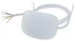
This Wire Extender can be mounted inside
the cabinet, on an exterior cabinet surface
or on a wall adjacent to the unit.
• The included harness is 36” (500 mm) long
to maximize installation flexibility.
• Mount the Wire Extender on a wall or fixed
appliance panel. DO NOT OBSTRUCT
access openings or panels.
Wiring Requirements
To be sure the installation location is
within easy reach of the appliance, it may
be easiest to connect the wiring before
mounting the device.
• Be sure to feed the wire through a hole
in the cabinet that is free of sharp edges
and allows access covers to be re-installed
before finalizing the installation.
• Use a maximum 100 feet (30 meters) of
18-gauge wire or 36 feet (11 meters) of
22-gauge wire between the Wire Extender
and the Thermostat.
• Wiring must comply with all applicable
local, state and national codes. In the
absence of local requirements, use ANSI/
NFPA 70, National Electrical Code.
Installation/
User
Guide
SA918 Wire
Extender with
Wire Harness
SOLO Wi-Fi Thermostat Jumper
Enable
Double-sided Adhesive
Mounting Screws
(888) 387-2587 • [email protected] • www.salusinc.com
Instructions may change without notice, always check
www.salusinc.com for the latest installation details.
Product Introduction
The SALUS SA918 Wire Ex
tender is a simple solution to allow
installation of SALUS SOLO Wi-Fi Thermostats with 2, 3 or 4 wire
connections.
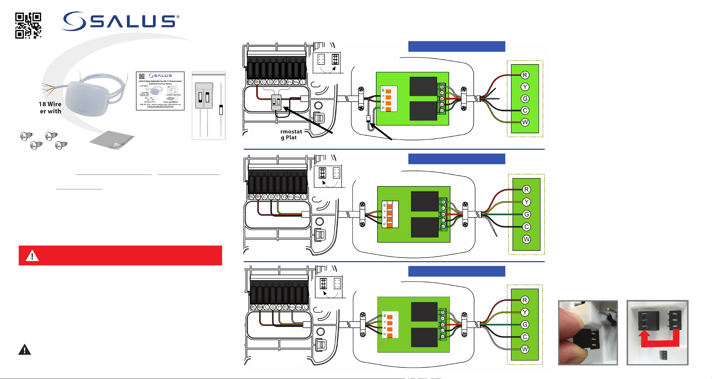
Installation The following wiring diagrams show electrical connections between a SOLO Wi-Fi Thermostat and the SA918 Wire Extender
as well as wiring between the Wire Extender and the appliance. To enable the internal diode pair in the Thermostat, move the jumper to the
outer position (shown below).
2-Wire Thermostat Replacement
Wi-Fi Thermostat
Mounting Plate
Appliance
SA918 Wire Extender
3-Wire Thermostat Replacement
Wi-Fi Thermostat
Mounting Plate
Appliance
SA918 Wire Extender
4-Wire Thermostat Replacement
Wi-Fi Thermostat
Mounting Plate
Appliance
SA918 Wire Extender
Disabled
Wi-Fi Thermostat
Jumper
Enabled
Wi-Fi Thermostat
Jumper
Enabled
Wi-Fi Thermostat
Jumper
Diode Pair
IN4004 Diode (or equal)
Diode
Pack
Specifications
FCC Statements
WARNING: Changes or modifications to
this unit not
expressly approved by the party responsible for
compliance could void the user’s authority to
operate the equipment.
This device complies with Part 15 of the FCC Rules.
Operation is subject to the following two conditions:
(1) this device may not cause harmful interference, and
(2) this device must accept any interference received,
including interference that may cause undesired operation.
NOTE: This equipment has been tested and found to
comply with the limits for a Class B digital device,
pursuant to Part 15 of the FCC Rules. These limits are
designed to provide reasonable protection
against harmful interference in a residential
installation. This equipment generates, uses and can radiate
radio frequency energy, and if not installed and used in
accordance with the instructions, may cause harmful
interference to radio communications. However, there is no
guarantee that interference will not occur in a particular
installation. If this equipment does cause harmful
interference to radio or television reception, which can
be determined by turning the equipment off and on, the
user is encouraged to try to correct the interference by
one or more of the following measures:
• Reorient or relocate the receiving antenna.
• Increase the separation between the equipment and
receiver.
• Connect the equipment into an outlet on a circuit
different from that to which the receiver is
connected.
• Consult the dealer or an experienced radio/TV
technician for help.
FCC and Industry Canada
RF Radiation Exposure statement: This equipment complies with
FCC and Industry Canada RF radiation exposure limits set forth
for an uncontrolled environment. This equipment should be
installed and operated with a minimum distance of 20
centimeters between the antenna and all persons.
Industry Canada
This device complies with Industry Canada license-exempt RSS
standard(s). Operation is subject to the following two
conditions: (1) this device may not cause interference, and (2)
this device must accept any interference, including
interference that may cause undesired operation of the device.
Le présent appareil est conforme aux
CNR d'Industrie
Canada applicables aux appareils radio exempts de licence.
L'exploitation est autorisée aux deux conditions suivantes : (1)
l'appareil ne doit pas produire de brouillage, et (2) l'utilisateur
de l'appareil doit accepter tout brouillage
radioélectrique subi, même si le brouillage est susceptible
d'en compromettre le fonctionnement.
Salus Warranty
SALUS North America, Inc. (“Salus”) warrants that for a period
of five (5) years (“Warranty Period”) from the date of
purchase by the consumer (“Customer”), this device,
excluding batteries (“Product”), shall be free of defects in
materials and workmanship under normal use and service in
accordance with all supplied instructions.
During the warranty period, Salus shall,
at its option,
repair or replace any defective Products, at no charge for
the device. Any replacement and/or repaired devices
are warranted for the remainder of the original
Warranty Period or ninety (90) days, whichever is
longer.
This warranty does not cover removal or
reinstallation costs. This warranty does not apply to any Product (i)
which has been modified, repaired, or altered, except by Salus
or an authorized Salus representative, (ii) which has not been
maintained in accordance with any handling or operating
instructions supplied by Salus, or (iii) which has been
subjected to unusual physical or electrical stress, misuses,
abuse, negligence, or accidents.
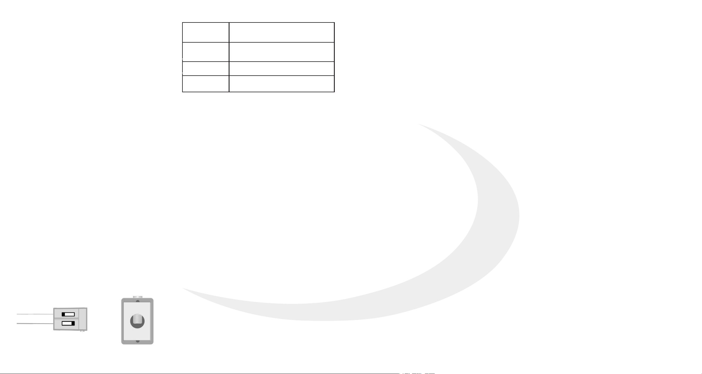
Operating
Conditions
32 - 104°F (0 - 40°C)
Max. RH 90% (non-condensing)
Storage
Conditions
-4 - 185°F (-20 - 85°C)
Max. RH 90% (non-condensing)
Power Input
24 VAC ± 10%
Dimensions
3.7” x 2.6” x 0.9”
9.4 cm x 6.6 cm x 2.3 cm
This warranty is the only express warranty Salus makes for the
Product. Any implied warranties, including warranties of
merchantability or fitness for a particular purpose, are limited to
the Warranty Period or the shortest period allowed by law.
SALUS SHALL NOT BE LIABLE FOR ANY LOSS OR DAMAGE OF ANY
KIND, INCLUDING ANY SPECIAL, INCIDENTAL OR CONSEQUENTIAL
DAMAGES RESULTING, DIRECTLY OR INDIRECTLY, FROM ANY
BREACH OF ANY WARRANTY, EXPRESS OR IMPLIED, OR ANY OTHER
FAILURE OF THIS PRODUCT.
Some states and provinces do not allow the exclusion or limitation
of incidental or consequential damages, or limitation on the
duration of implied warranties of merchantability or fitness, so
these exclusions or limitations may not apply to you.
No oral or written information or advice given by Salus or a Salus-
authorized representative shall modify or extend this warranty. If
any term is held to be illegal or unenforceable, the legality or
enforceability of the remaining terms shall not be affected or
impaired.
Customer’s sole and exclusive remedy under this limited warranty
is product repair or replacement as provided herein. If a Product
under warranty is defective, the Customer may:
• Contact the party (“Seller”) from which the Customer purchased
the Product to obtain an equivalent replacement product after
the Seller has determined that the Product is defective
and the
Customer is eligible for a replacement, or
• Contact Salus Service at [email protected], to determine
whether the device qualifies for
a replacement. If a replacement is warranted and is shipped prior
to the return of the device under warranty, a credit card is
required and a hold may be placed on the Customer’s credit card
for the value of the replacement until the returned device is
verified as eligible for replacement, in which case, the Customer’s
credit card will not be charged.
This warranty gives you specific legal rights, and you may also have
other rights that vary from jurisdiction to jurisdiction. If you have
any questions regarding this warranty, please write Salus at:
SALUS North America, Inc.
4700 Duke Drive, Suite 200
Mason, OH 45040
SMC-QG-SA918-EN-202108v3
Connecting the SA918
Carefully examine the wiring that connects to your
existing thermostat. If there is no "C" wire
(common), you will need to use the SA918 Wire
Extender to connect your new SOLO thermostat to
your system.
Note: Other thermostats may have different
termination requirements.
The number of wires, and where they connect on
the existing thermostat will guide you in how to
connect the SA918.
The 3 diagrams on the previous page are the most
common for heating, cooling, and heat/cool
systems.
Newer systems will typically have a 3 or 4-wire
connection between the equipment and the
thermostat. Older systems often only have 2 wires
and require the addition of the enclosed diodes.
The single diode is connected to the SA918 "Y" &
"G" terminals with the polarity as shown.
The leads of the diode pair are typically connected
to the "C" and "W1" terminals on the thermostat
terminal block. with the polarity as shown.
The power wire, typically red, connects to the "R"
terminal while the second wire, typically black, is
connected to the screw terminal on the top of the
diode pair.
Be certain to position the diode pair housing so
that it will be recessed in the wall opening.