2710-20
AC/DC 18 Volt Battery Charger
June 2009
FIG. PART NO. DESCRIPTION OF PART NO. REQ.
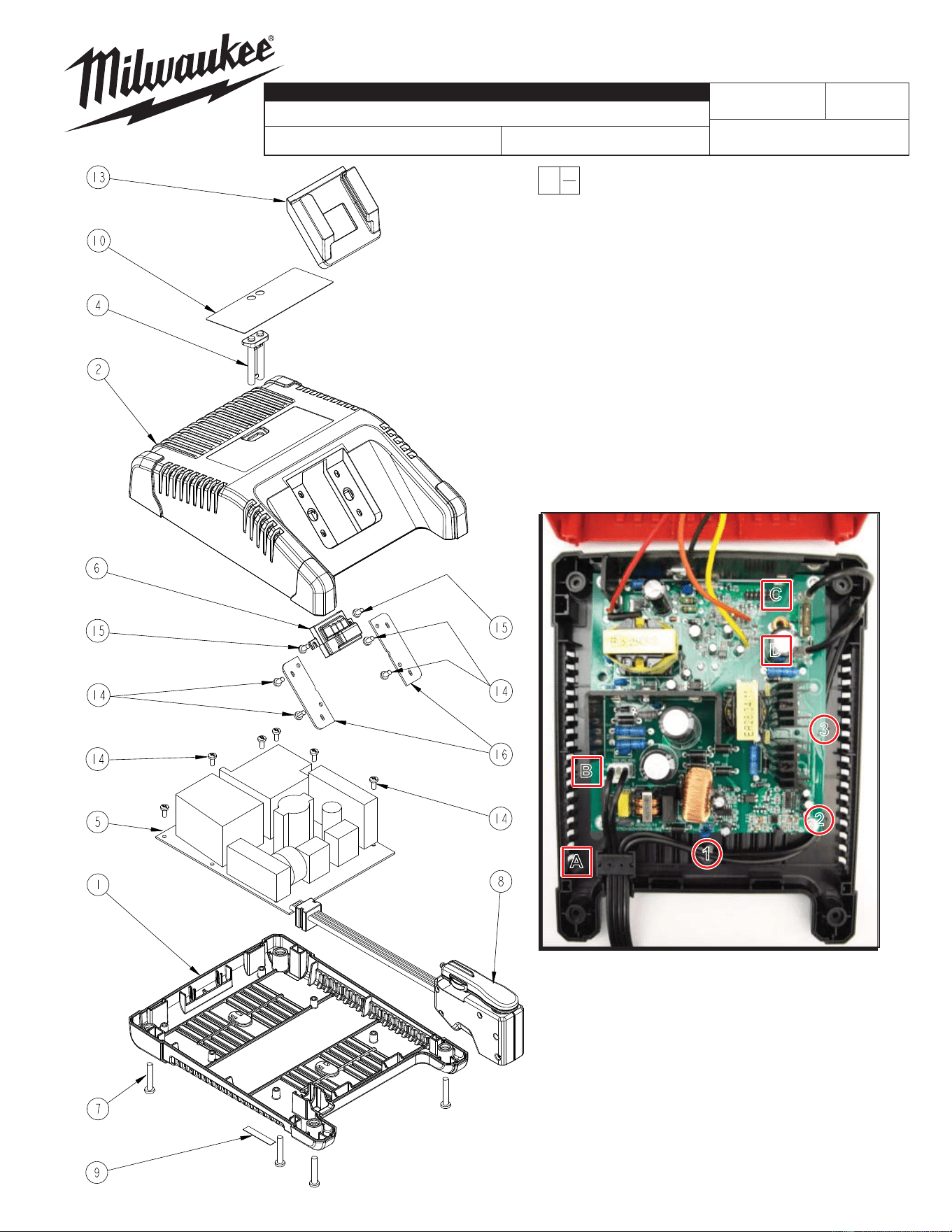
1 --------------- Housing Bottom (1)
2 --------------- Housing Top (1)
4 --------------- Light Pipe (2)
5 --------------- PCB Assembly (1)
6 --------------- Terminal Board (1)
7 --------------- 8-16 x 1.00" Slt. Plastite T-20 Screw (4)
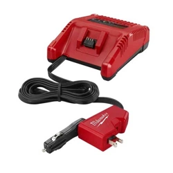
8 22-64-1200 AC/DC Power Cord (1)
9 12-20-1805 Service Nameplate (1)
10 --------------- Charger Label (1)
13 --------------- Battery Insert (1)
14 --------------- 6-19 x .31 Slt. Plastite T-15 Screw (10)
15 --------------- 4-20 x .31 Slt. Plastite T-10 Screw (2)
16 --------------- Cover (1)
FIG. NOTES
1, 9 A clean, dry surface is essential for proper performance
for anyadhesive system. The area intended for application
of any adhesive label or nameplate must be prepared by
cleaning with isopropyl alcohol. The solvent is to be applied
with a clean, lint free applicator and the surface allowed to
dry before applying the label or nameplate.
54-04-1805
REVISED BULLETIN
SERVICE PARTS LIST
BULLETIN NO.
WIRING INSTRUCTION
DATE
CATALOG NO.
SPECIFY CATALOG NO. AND SERIAL NO. WHEN ORDERING PARTS
SERIAL
NUMBER
MILWAUKEE ELECTRIC TOOL CORPORATION
13135 W. LISBON RD., BROOKFIELD, WI 53005
Drwg. 1
EXAMPLE:
Component Parts (Small #) Are Included
When Ordering The Assembly (Large #).
0
00
C03A
2
1
3
A
B
D
C
REPLACING AC/DC POWER CORD:
Place molded strain relief block of power cord in rectangular •
cavity [A] in housing bottom. Seat block completely down.
Attach connector block from the two short power cord wires to the•
pin location on circuit board marked '120 VAC 60Hz' [B].
Route the two long power cord wires through wire trap [1]. Press•
wires down in trap and place a dap of silicone adhesive over the
wires at that trap location (do this after long wires are completely routed).
Remove the two screws on the right side of the circuit board and •
carefully lift the circuit board enough to place the long power cord
wires in traps [2 & 3]. Replace screws to secure wires in traps.
Attach wire with larger terminal connector to terminal on circuit •
board marked '+12V Input' [C].
Attach wire with smaller terminal connector to terminal marked •
'Gnd Input' [D] on circuit board.