
7" POLISHER
241-0809
OPERATOR’S MANUAL
CAUTION: To Reduce The Risk Of Injury, User Must Read And
Understand Operator's Manual. Save These Instructions For Future Reference.
For questions about this product, please call 1-866-915-8626

page 2
SAFETY INSTRUCTIONS
The term “power tool” in the warnings refers to your corded power tool or battery-operated
(cordless) power tool.
1) WORK AREA SAFETY
a) Keep work area clean and well lit. Cluttered or dark areas invite accidents.
b) Do not operate power tools in explosive atmospheres, such as in the presence of
flammable liquids, gases or dust. Power tools create sparks which may ignite the dust or
fumes.
c) Keep children and bystanders away while operating a power tool. Distractions can
cause you to lose control.
2) ELECTRICAL SAFETY
a) Power tool plugs must match the outlet. Never modify the plug in any way. Do not
use any adapter plugs with grounded power tools. Unmodified plugs and matching
outlets wi
ll reduce risk of electric shock.
b) Avoid body contact with grounded surfaces such as pipes, radiators,
ranges and refrigerators. There is an increased risk of electric shock if your body is grounded.
c) Do not expose power tools to rain or wet conditions. Water entering a power tool will
increase the risk of electric shock.
d) Do not abuse the cord. Never use the cord for carrying, pulling or unplugging the
power tool. Keep cord away from heat, oil, sharp edges or moving parts. Damaged
or entangled cords increase the risk of electric shock.
e) When operating a power tool outdoors, use an extension cord suitable for outdoor
use. Use of a cord suitable for outdoor use reduces
the risk of electric shock.
f) If operating a power tool in a damp location is unavoidable, use a ground fault
circuit interrupter (GFCI) protected supply. Use of a GFCI reduces the risk of electric
shock.
3) PERSONAL SAFETY
a) Stay alert, watch what you are doing and use caution when operating a power
tool. Do not use a power tool while you are tired or under the influence of
drugs, alcohol or medication. A moment of inattention while operating power tools may
result in serious personal injury.
b) Use personal protective equipment. Always wear eye protection. Protective equipment
such as dust mask, non-skid safety shoes, hard hat, or hearing protection used for appropriate
conditions will reduce personal injuries.
c) Prevent unintentional starting. Ensure the switch is in the off position before
connecting to power source and/or battery pack, picking up or carrying the tool.
Carrying power tools with your finger on the switch or energizing power tools that have the
switch on invites accidents.
d) Remove any adjusting key or wrench before turning the power tool on. A wrench or
a key left attached to a rotating part of the power tool may result in personal injury.
e) Do not overreach. Keep proper footing and balance at all times. This enables better
control of the power tool in unexpected situations.
f) Dress properly. Do not wear loose clothing or jewelry. Keep your hair, clothing and
gloves away from moving parts. Loose clo
thes, jewelry or long hair can be caught in
moving parts.
g) If devices are provided for the connection of dust extraction and collection facilities,
ensure these are connected and properly used. Use of dust collection can reduce dust-
related hazards.
TABLE OF CONTENTS
Safety Instructions........................ Page 2
Safety Symbols.............................. Page 5
Description..................................... Page 5
Operation....................................... Page 7
Application..................................... Page 8
Maintenance.................................. Page 9
Part list.......................................... Page 10
Schematic drawing...................... Page11
Warranty....................................... Page 12

a)
page 3
4) POWER TOOL USE AND CARE
Do not force the power tool. Use the correct power tool for your application. The
correct power tool will do the job better and safer at the rate for which it was designed.
b) Do not use the power tool if the switch does not turn it on and off. Any power tool
that cannot be controlled with the switch is dangerous and must be repaired.
c) Disconnect the plug from the power source and/or the battery pack from the power
tool before making any adjustments, changing accessories, or storing power tools.
Such preventive safety measures reduce the risk of starting the power tool accidentally.
d) Store idle power tools out of the reach of children and do not allow persons
unfamiliar with the power tool or these instructions to operate the power tool. Power
tools are dangerous in the hands of untrained users.
e) Maintain power tools. Check for misalignment or binding
of moving parts, breakage
of parts and any other condition that may affect the power tool’s operation. If
damaged, have the power tool repaired before use. Many accidents are caused by
poorly maintained power tools.
f) Use the power tool, accessories and tool bits etc., in accordance with these
instructions taking into account the working conditions and the work to be
performed. Use of the power tool for operations different from those intended could result
in a hazardous situation.
Safety Instructions for All Operations
a) This power tool is intended to function as a polisher. Read all safety warnings,
instructions, illustrations and specifications provided with this power tool. Failure to
follow all
instructions listed below may result in electric shock, fire and/or serious injury.
b) Operations such as grinding, sanding, wire brushing or cutting-off are not
recommended to be performed with this power tool. Operations for which the power
tool was not designed may create a hazard and cause personal injury.
c) Do not use accessories which are not specifically designed and recommended by
the tool manufacturer. Just because the accessory can be attached to your power tool, it
does not assure safe operation.
d) The rated speed of the accessory must be at least equal to the maximum speed
marked on the power tool. Accessories running faster than their rated speed can break
and
fly apart.
e) The outside diameter and the thickness of your accessory must be within the
capacity rating of your power tool. Incorrectly sized accessories cannot be adequately
guarded or controlled.
f) The arbor size of wheels, flanges, backing pads or any other accessory must
properly fit the spindle of the power tool. Accessories with arbor holes that do not match
the mounting hardware of the power tool will run out of balance, vibrate excessively and may
cause loss of control.
g) Do not use a damaged accessory. Before each use inspect the accessory such as
abrasive wheels for chips and cracks, backing pad for cracks, tear or excess wear.
If power
tool or accessory is dropped, inspect for damage or install an undamaged
accessory. After inspecting and installing an accessory, position yourself and
bystanders away from the plane of the rotating accessory and run the power
tool at maximum no-load speed for one minute. Damaged accessories will normally
break apart during this test time.
h) Wear personal protective equipment. Depending on application, use face shield,
safety goggles or safety glasses. As appropriate, wear dust mask, hearing
protectors, gloves and workshop apron capable of stopping small abrasive or
workpiece fragments. The eye protection must be capable of stopping flying debris
generated by various operations. The dust mask or respirator must be capable of filtrating

page 4
i) Keep bystanders a safe distance away from work area. Anyone entering the work
area must wear personal protective equipment. Fragments of workpiece or of a broken
accessory may fly away and cause injury beyond immediate area of operation.
j) Position the cord clear of the spinning accessory. If you lose control, the cord may be
cut or snagged and your hand or arm may be pulled into the spinning accessory.
k) Never lay the power tool down until the accessory has come to a complete stop. The
spinning accessory may grab the surface and pull the power tool out of your control.
i) Do not run the power tool while carrying it at your side. Accidenta
l contact with the
spinning accessory could snag your clothing, pulling the accessory into your body.
m) Regularly clean the power tool’s air vents. The motor’s fan will draw the dust inside the
housing and excessive accumulation of powdered metal may cause electrical hazards.
n) Do not operate the power tool near flammable materials. Sparks could ignite these
materials.
o) Do not use accessories that require liquid coolants. Using water or other liquid coolants
may result in electrocution or shock.
Safety Warnings Specific for Polishing Operations
a) Do not allow any loose portion of the polishing bonnet or its attachment strings
to spin freely. Tuck away or trim any loose attachment strings. Loose and spinning
attachment strings can
entangle your fingers or snag on the workpiece.
Additional Specific Safety Instructions for Polishers
• Clean out your tool often, especially after heavy use. Dust and grit containing metal
particles often accumulate on interior surfaces and could create an electric shock hazard.
• Do not operate this tool for long periods of time. Vibration caused by the operating action
of this tool may cause permanent injury to fingers, hands and arms. Use gloves to provide extra
cushion, take frequent rest periods and limit daily time of use.
• Air vents often cover moving parts and should be avoided. Loose clothes, jewelry or long
hair can be caught in
moving parts.
• An extension cord must have adequate wire size (AWG or American Wire Gauge) for
safety. The smaller the gauge number of the wire, the greater the capacity of the cable, that is
16 gauge has more capacity than 18 gauge. An undersized cord will cause a drop in line voltage
resulting in loss of power and overheating. When using more than one extension to make up
the total length, be sure each individual extension contains at least the minimum wire size. The
following table shows the correct size to use depending on cord length and nameplate ampere
rating. If in doubt, use the next heavier gauge. The sm
aller the gauge number, the heavier the
cord.
Minimum Gauge for Cord Sets
Ampere Rating
Volts Total Length of Cord in Feet (meters)
120V 25 (7.6) 50 (15.2) 100 (30.5) 150 (45.7)
240V 50 (15.2) 100 (30.5) 200 (61.0) 300 (91.4)
More
Than
Not More
Than
AWG
0 6 18 16 16 14
6 10 18 16 14 12
10 12 16 16 14 12
12 16 14 12 Not Recommended
particles generated by your operation. Prolonged exposure to high intensity noise may cause
hearing loss.
• Always use eye protection. All users and bystanders must wear eye protection that conforms
to ANSI Z87.1.
page 5
• The label on your tool may include the following symbols. The symbols and their definitions are
as follows:
serepma................ A stlov...................... V
sttaw............... W ztreh.................... zH
min ..................minutes
.............alternating current
...............direct current .............alternating or direct current
....................Class I Construction
n
o ..............no-load speed
........................(grounded)
...............earthing terminal
....................Class II Construction ..............safety alert symbol
........................(double insulated) BPM ...........beats per minute
…/min .............per minute RPM ...........revolutions per minute
DESCRIPTION
SAFETY SYMBOLS
Motor
Be sure your power supply agrees with the nameplate marking. Voltage decrease of more than 10% will
cause
loss of power and overheating. The tools are factory tested; if this tool does not
operate, check power supply.
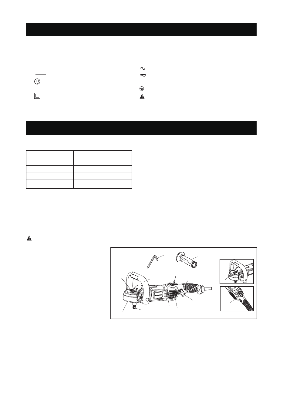
COMPONENTS (Fig. 1)
WARNING:
Never modify the power tool or any part of it. Damage or personal injury could
result.
A. Speed control wheel
B. Inner hexagon wrench
C. Trigger switch
D. Brush inspection cap
E. Spindle lock button
F. Auxiliary handle
G. Trigger locking button
H. Bale handle
I. Spindle
J. Soft rubber gear case cover
K. Wool ingestion shield
INTENDED USE
Heavy-duty polishers are designed for polishing painted or unnished metal, berglass, and
composite surfaces in professional applications. Common examples of use include but are not
limited to: auto/marine/RV/motorcycle detailing and nish correction, boat construction and
repair, and metal or concrete nishing.
Do not use in the presence of ammable liquids or gases. Do not let children come into contact
with the tool. Supervision is required when inexperienced operators use this tool.
FIG. 1
F
B
H
E
I
D
C
G
A
K
J
E
A
Rating 120 V 60Hz
Motor 12 Amp
Variable Speed 600-3000RPM
Disc diameter 7"
Arbor size 5/8"
SPECIFICATIONS

page 6
Speed Control Wheel (Fig. 1)
It is important to remember two things about electronic speed control:
1. The electronic speed control operates only when the trigger switch (C) is fully depressed.
2. The effect of electronic speed control is much easier to observe at lower speed settings
(2600 RPM and below), than at high speeds. As the tool approaches 3200 RPM, the effect is
considerably less dramatic.
Spindle Lock Button (Fig. 1)
Wool Ingestion Shields (Fig. 1, 2)
Trigger Switch (Fig. 1)
Auxiliary Handle (Fig. 1)
An auxiliary handle (F) is provided with your tool and can be installed on either side of the gear
case. This handle should be used at all times to maintain complete control of the tool.
There is a bale handle (H) which can be used in place of the auxiliary handle. You can use the inner hexagon
wrench (B) to install or release the bale handle(H).
WARNING: To reduce the risk of serious personal injury, turn tool off and disconnect
tool from power source before making any adjustments or removing/installing
attachments or accessories. Before reconnecting the tool, depress and release the
trigger switch to ensure that the tool is off.
In order to prevent the spindle of the tool from rotating while installing or removing accessories, a
spindle lock button (E) has been provided in the gear head of the machine. To lock the spindle,
depress and hold the lock button. NEVER DEPRESS THE SPINDLE LOCK BUTTON WITH
THE TOOL RUNNING OR COASTING.
The wool ingestion shields (K) are designed to
reduce the amount of wool, dust, and debris that
gets ingested by the motor during normal use. The
goal of the ingestion shields is to improve
durability as compared to a unit without the ingestion
shields.
Each ingestion shield can be easily removed for
cleaning by removing the mounting screw (L),
followed by sliding the shield back towards the
trigger end of the tool and then lifting it off.
FIG. 2
K
L
The tool operation can be locked on for continuous use by depressing the trigger switch (C) fully
and depressing the lock button (G) shown in Figure 1. Hold down the lock button while simultan-
eously releasing the trigger switch (C) . The tool will continue to run. To turn the tool off from a
locked-on position, fully depress and release the trigger switch (C) once. Do not unplug the tool
with the switch in the locked-on condition. Make sure the tool is not locked on when plugging in.
The wool ingestion shields can be cleaned with soap and water and a soft bristle brush in the
event they get clogged with polish and debris. Clean the shields as soon as you start to see
buildup on the outside.
The tool speed can be changed by turning the speed control wheel to any one of six speeds.
Speed at 1:600 RPM
Speed at 2:1,000 RPM
Speed at 3:1,500 RPM
Speed at 4:2,000 RPM
Speed at 5:2,500 RPM
Speed at 6:3,000 RPM
WARNING:The high speed settings are intended for sanding. If used for polishing an excessive
amount of surface material may be removed.
page 7
OPERATION
Soft Rubber Gear Case Cover (Fig. 1)
The soft rubber gear case cover (J) is designed to eliminate metal gear case scuffs on painted or
polished surfaces.
The soft rubber gear case cover can be removed if required. To take off the cover, remove the
three mounting screws and lift the cover over the gear case.
WARNING: To reduce the risk of serious personal injury, turn tool off and disconnect
tool from power source before making any adjustments or removing/installing
attachments or accessories. Before reconnecting the tool, depress and release the
trigger switch to ensure that the tool is off.
FIG. 3A
M
N
O
E
I
I
Q
FIG. 3B
E
E
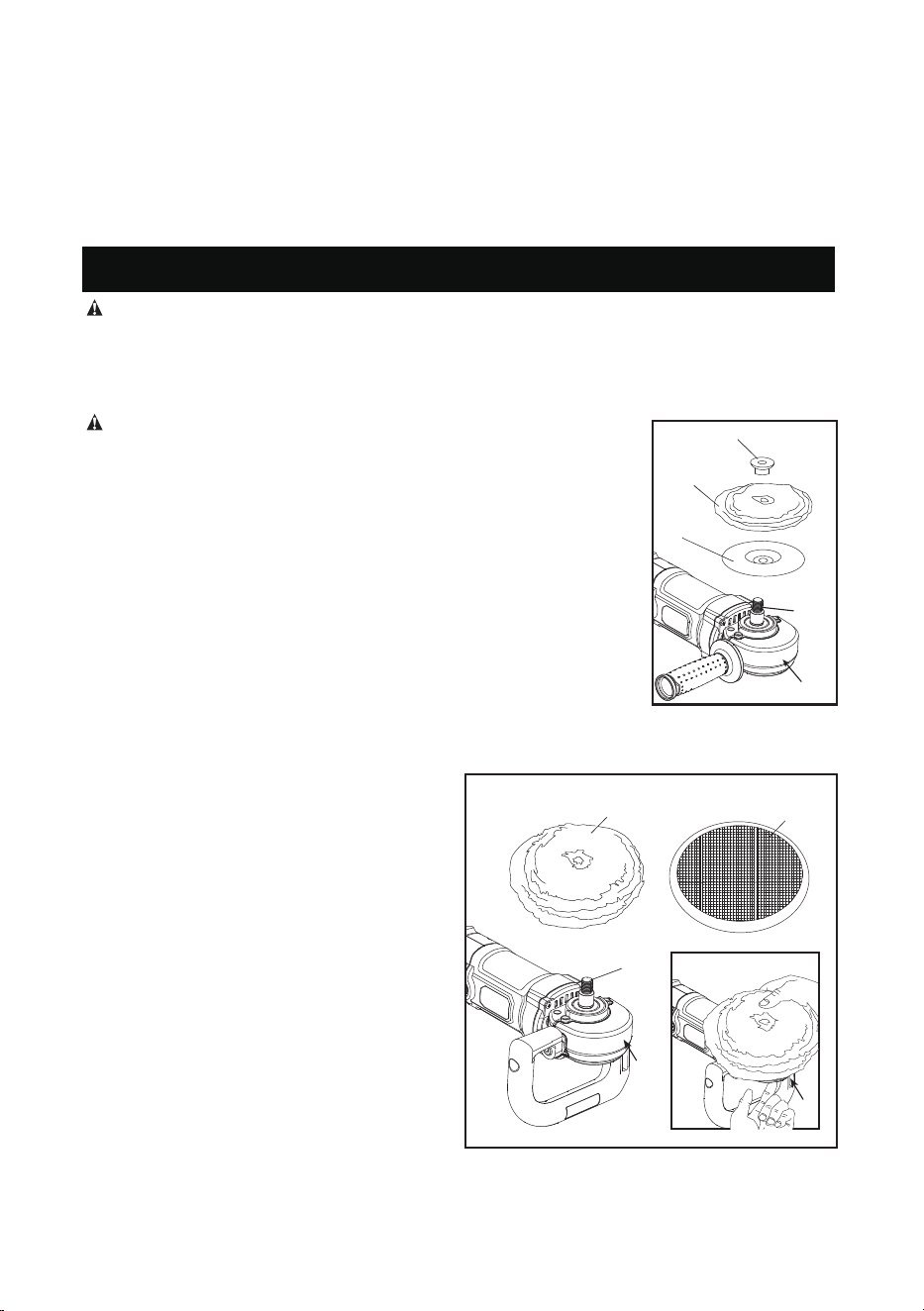
Attaching and Removing Polishing Pads (Fig. 3A&3B)
WARNING: To reduce the risk of serious personal injury, do not allow
1. Attach hook and loop foam or wool pad (P)
to hook and loop backing pad (Q), being
careful to center the backing pad (Q) with
the foam or wool pad.
2. Screw backing pad (Q) onto spindle (I),
while depressing spindle lock button (E).
any loose portion of the polishing bonnet or its attachment strings to spin
freely. Tuck away or trim any loose attachment strings. Loose and spinning
attachment strings can entangle your fingers or snag on the workpiece.
NOTE: This tool may use either type of polishing pad assembly described
below.
TO ATTACH POLISHING PAD WITH RUBBER BACKING PAD (FIG. 3A)
1. To attach polishing pad (N), push the hub of the clamp washer (M) through
the hole in the center of the polishing pad as far as it will go.
2. Engage the hexagonal hole in the backing pad (O). Holding the three pieces
rmly together, place the assembly on the tool spindle (I).
3. Depress the spindle lock button (E) while turning the pads clockwise to thread
them
completely on the spindle.
TO ATTACH POLISHING PAD WITH HOOK AND LOOP BACKING PAD (FIG. 3B)
TO REMOVE PADS
Depress the lock button (E) and turn the pad
by hand in the opposite direction until the pad
snaps into the lock position.
Once the pad is snapped into the lock position
ensure the pad is locked well by once again
turning the pad in the left and right direction
while still depressing the lock button (E).
If the pad is locked well it should not be possible
to turn the pad.
Then unscrew pads in normal direction for right
handed thread.
P
page 8
APPLICATION
These instructions and suggestions are intended to familiarize new operators in overall general
operation of power polishing. You will develop your own techniques which will make the job easier
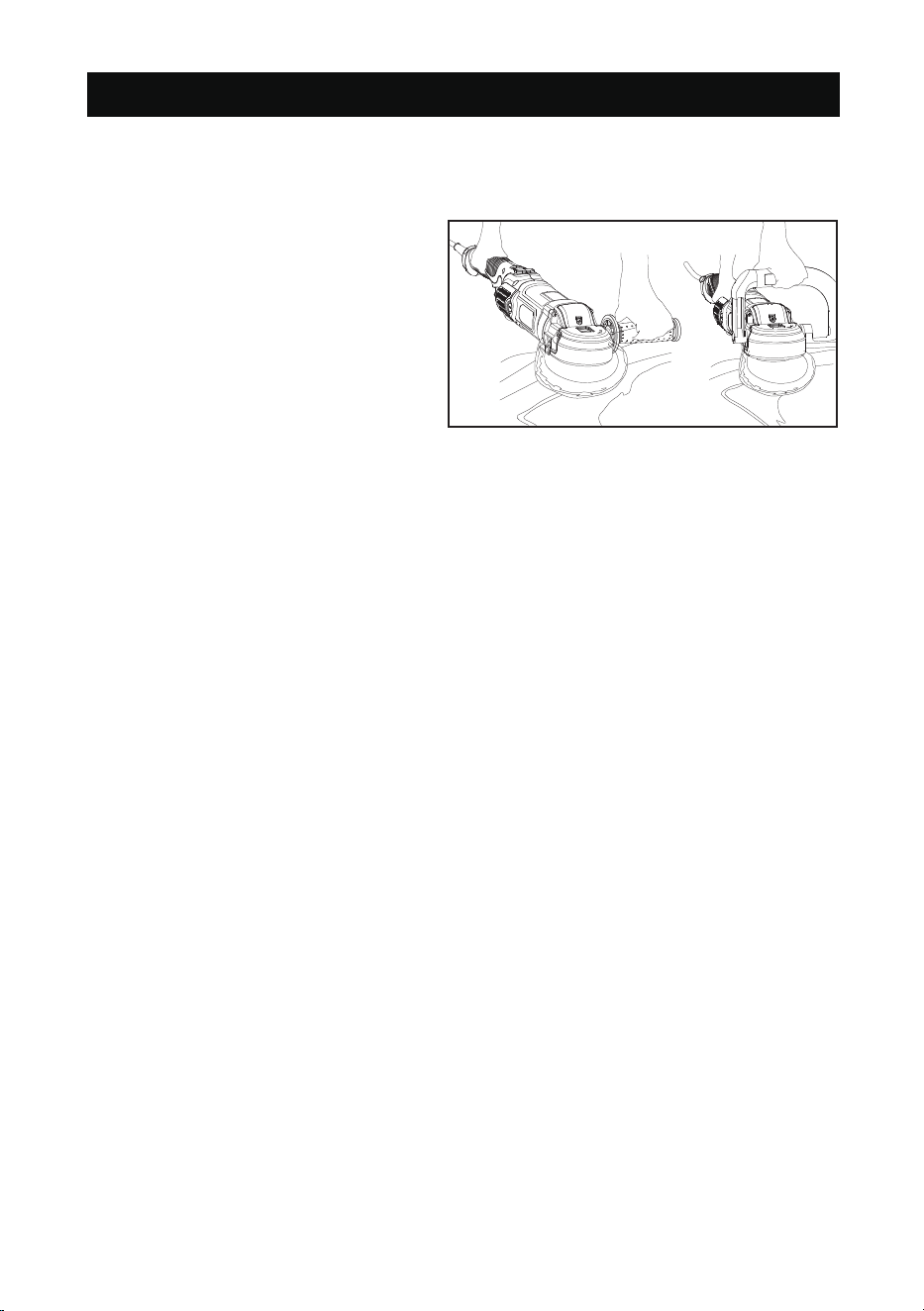
and faster as you learn power polishing.(FIG.4)
• You should use utmost care when power
polishing around or over sharp objects and
contours of the car body. It is very important
to use the correct pressure while polishing
various sections of an automobile body. For
example, light pressure should be applied
when polishing over sharp edges of body
panels, or over edges of the rain gutter along
the top.
• Since everyone does not use the same type
of power polish, we recommend you clean
and polish a test section on a at area of the
car rst. From this test section, you can judge
the strength or cleaning action of your power
polish.
• Remember, all power polish is not the same. Different brands will react differently on various painted
surfaces. Also, you are now using a power polisher with power polish. This is entirely different from
any hand application which you may have done before. Wash the car before power polishing it.
Washing will remove loose dirt, scum, road salt, etc. which could act as an abrasive and damage
paint. Loose dirt, etc. will also clog the polishing pad and you will have to clean it more often.
• Without turning the tool on, grasp the handles of the tool and pick it up (Fig. 4). Keep the tool away
from your body and depress the trigger switch. Make sure you have a rm grip on the handles and
operate the tool freely without forced effort or unnecessary pressure. The side handle can be easily
changed to either side of the tool for left-handed or right-handed operation.
NOTE: The high speed rubbing action of the polishing bonnet upon the surface of an automobile
can build a static charge on the metal portions of this tool. This can result in a sensation of a very
short mild electric shock when the metal area of the tool is touched, and will be more noticeable
on days when the humidity is low. This is a harmless phenomenon but if you need assistance you
can contact our customer service center at:1-866-915-8626.
FIG. 4

The power tool has been designed to operate over a long period of time with a minimum of
maintenance. Continuous satisfactory operation depends upon proper tool care and regular
cleaning.
WARNING: To reduce the risk of serious personal injury, turn tool off and disconnect
tool from power source before making any adjustments or removing/installing
page 9
MAINTENANCE
attachments or accessories. Before reconnecting the tool, depress and release the
trigger switch to ensure that the tool is off.
Cleaning
WARNING: Blow dirt and dust out of all air vents with dry air at least once a week. Wear proper
ANSI Z87.1 (CAN/CSA Z94.3) eye protection and proper NIOSH/OSHA/MSHA respiratory
protection when performing this.
WARNING: Never use solvents or other harsh chemicals for cleaning the non-metallic parts of
the tool. These chemicals may weaken the plastic materials used in these parts. Use a cloth
dampened only with water and mild soap. Never let any liquid get inside the tool; never immerse
any part of the tool into a liquid.
Motor Brushes
Be sure tool is unplugged before inspecting brushes. Carbon brushes should be regularly inspected
for wear. To inspect brushes, unscrew the plastic brush inspection caps (located in the sides of the
motor housing) so the spring and brush assemblies may be withdrawn from the tool. Keep brushes
clean and sliding freely in their guides. Carbon brushes have varying symbols
stamped into them,
and if the brushes are worn down to the line closest to the spring, they must be replaced.
Accessories
WARNING:
Since accessories, other than those offered by manufacturer
, have not been tested with
this product, use of such accessories with this tool could be hazardous. To reduce the risk of injury,
only
manufacturer
recommended accessories should be used with this product.
Recommended accessories for use with your tool are available at extra cost from your local dealer
or authorized service center.
Use only accessories having a maximum operating speed at least as high as the highest “NO LOAD
RPM” marked on the tool’s nameplate. This precaution applies to any accessory on any tool.
• 7" (180mm) hook and loop backing pads
• Wool ingestion shields
• Auxiliary handle
• Bale handle
• Inner hexagon wrench
•
Carbon brush

page 10
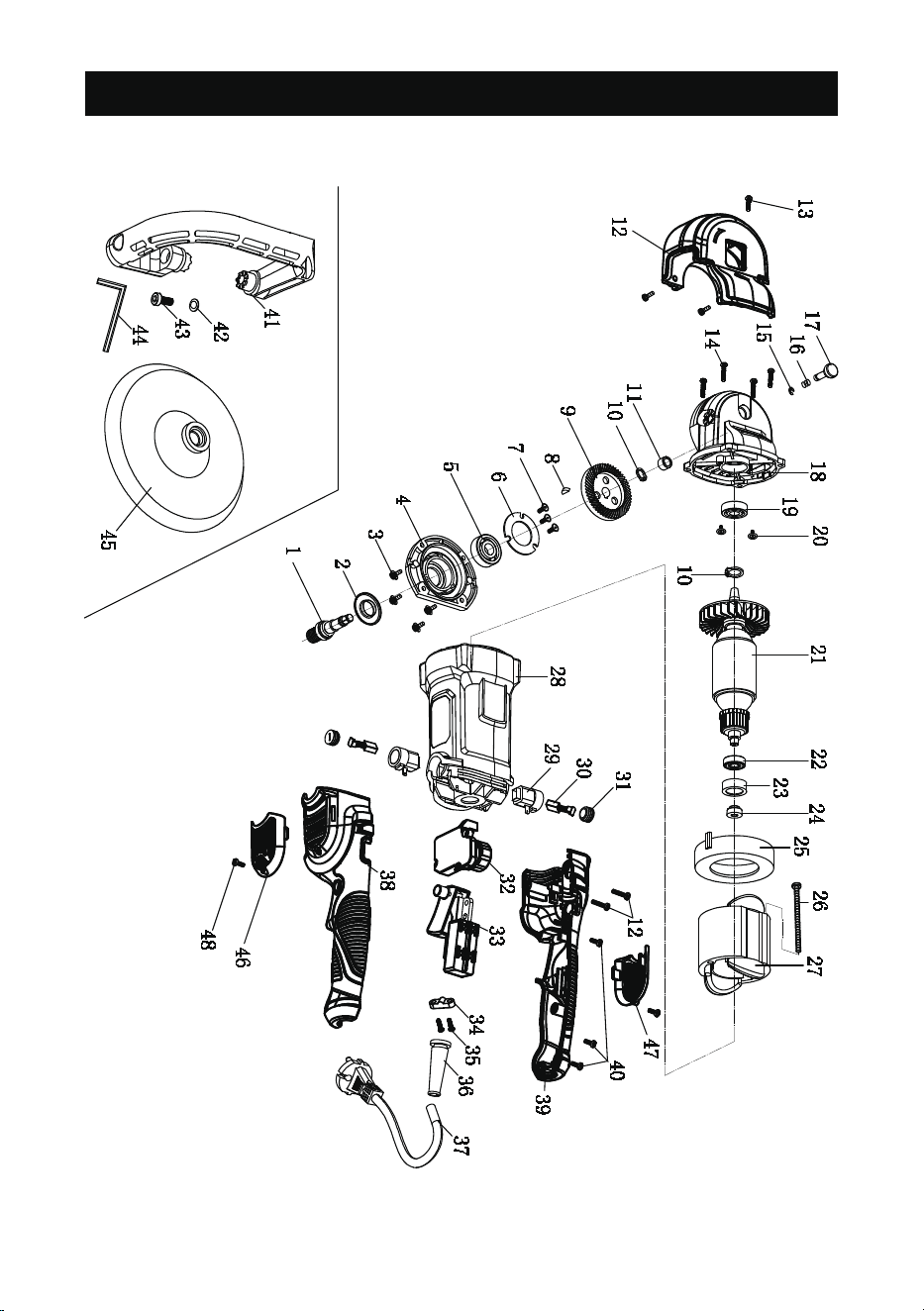
PART LIST
No.
1
2
3
4
5
6
7
8
9
10
11
12
13
14
15
16
17
18
19
20
21
22
23
24
QTY
1
1
4
1
1
1
5
1
1
2
1
1
3
4
1
1
1
1
1
1
1
1
1
1
Description
Main Shaft
Dust Cover
Tapping Screw
Front Cover
6201 Bearing
6201 Bearing Plate
Tapping Screw
Woodruff Key
Big Gear(47 teech)
Shaft Ring
needle bearing
gearbox cover
Tapping Screw
Tapping Screw
Shaft Ring
Self locking Pin Spring
Self locking Pin Assembly
Aluminium Alloy Part
6000 Bearing
6000 Bearing Plate
Armature Assembly
608 Bearing
608 Bearing Sleeve
Magnet Ring
No.
25
26
27
28
29
30
31
32
33
34
35
36
37
38
39
40
41
42
43
44
45
46
47
48
QTY
1
2
1
1
2
2
2
1
1
1
2
1
1
1
1
3
1
2
2
1
1
1
1
2
Description
Fan Shroud
Tapping Screw
Stator Assembly
central body housing
carbon brush holder
carbon brush
carbon brush holder cover
Speed Controller
Switch
Cable Clip
Tapping Screw
Cable Shield
Cable
Left handle housing
Right handle housing
Tapping Screw
D-shaped handle
M8 Flat Gasket
M8X30 Socket Head Screw
6mm Hex Wrench
Backing Plate
Left Cover
Right Cover
Tapping Screw
page 11
SCHEMATIC DRAWING

page 12
This MASTERFORCE® brand power tool carries our famous No Hassle 3-Year
Limited Warranty to the original purchaser. If, during normal use, this MASTER-
FORCE® power tool breaks or fails due to a defect in material or workmanship
within three (3) years from the date of original purchase, simply bring the tool
with the original sales receipt back to your nearest MENARDS® retail store. At
its discretion, MASTERFORCE® agrees to have the tool or any defective part(s)
repaired or replaced with the same or similar MASTERFORCE® product or part
free of charge, within the stated warranty period, when returned by the original
purchaser with original sales receipt. Not withstanding the foregoing, this limited
warranty does not cover any damage that has resulted from abuse or misuse of
the Merchandise.
This warranty: (1) excludes expendable parts including but not limited to blades,
brushes, belts, bits, light bulbs, and/or batteries; (2) shall be void if this tool is
used for commercial and/or rental purposes; and (3) does not cover any losses,
rights and you may have other rights, which vary from state to state. Be careful,
tools are dangerous if improperly used or maintained. Seller’s employees are not
made will not be binding on seller or its employees. The rights under this limited
warranty are to the original purchaser of the merchandise and may not be trans-
ferred to any subsequent owner. This limited warranty is in lieu of all warranties,
particular purpose. Seller shall not be liable for any special, incidental, or conse-
quential damages. The sole exclusive remedy against the seller will be for the
replacement of any defects as provided herein, as long as the seller is willing or
able to replace this product or is willing to refund the purchase price as provided
above. For insurance purposes seller is not allowed to demonstrate any of these
power tools for you.
For questions / comments, technical assistance or repair parts -
Please call toll free at: 1-866-915-8626 (M-F 8am - 6pm)
SAVE YOUR RECEIPTS
THIS WARRANTY IS VOID WITHOUT THEM
7” POLISHER
3-YEAR
LIMITED WARRANTY

© 2018 Menard, Inc., Eau Claire, WI 54703 01/2018
