
241-0335
3”x18’’ BELT SANDER
OPERATOR’S MANUAL
CAUTION:
To Reduce the Risk of Injury, User Must
Read and Understand the Operator’s Manual. Save These
Instructions For Future Reference.
For questions / comments, technical assistance or repair parts –
Please Call Toll Free: 1-866-917-4374 (M-F 8:30am-5:00pm EST).

TABLE OF CONTENTS
Safety Symbols ......................................................... Page 2
Safety Instructions ...................................................... Page 3
Overview/Specications ................................................. Page 7
Assembly ............................................................. Page 8
Operation ............................................................. Page 9
Maintenance .......................................................... Page 12
Troubleshooting ....................................................... Page 13
Parts List ............................................................. Page 14
Schematic Drawing .................................................... Page 15
Warranty .............................................................Page 18
Page 2
SAFETY SYMBOLS
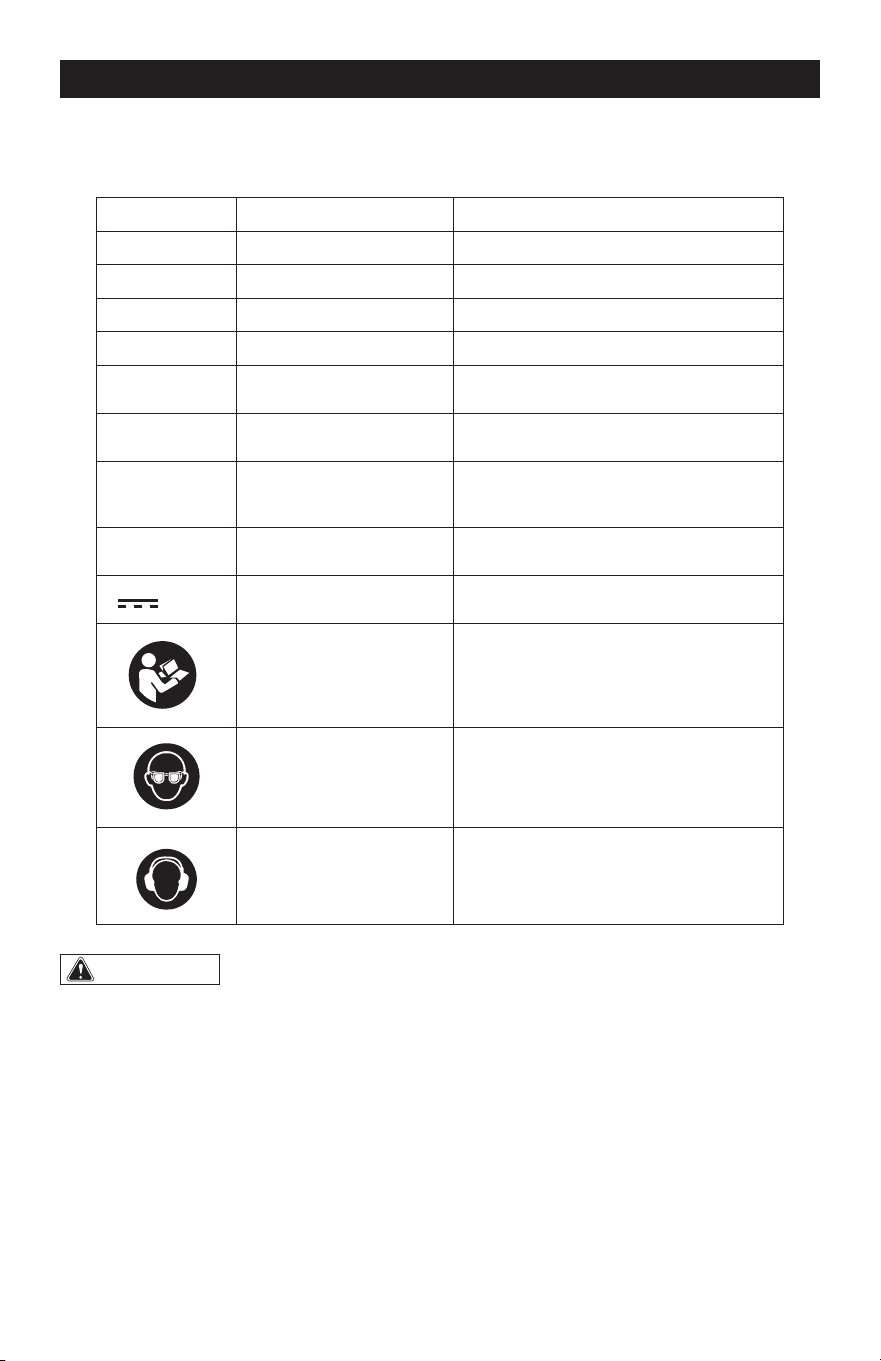
Some of these following symbols may be used on this tool. Please study them and learn their
meaning. Proper interpretation of these symbols will allow you to operate the tool better and
more safely.
Symbol
Name
Designation/Explanation
V Volts Voltage
A Amps Current
Hz Hertz Frequency (cycles per second)
W Watts Power
lbs Pounds Weight
n
0
No-load speed Rotational speed at no load
…/min Per minute
Revolutions, strokes, surface speed
orbits, etc., per minute
SFPM Surface feet per minute Unit of belt speed
or d.c.
Direct current Type or characteristic of current
Read instruction manual
To reduce the risk of injury, user must
read instruction manual.
Wear eye protection
To reduce the risk of injury, always
wear eye protection.
Wear hearing protec-
tion
To reduce the risk of injury, always
wear ear protection.
WARNING:
To ensure safety and reliability, all repairs should be performed by a
qualified service technician.
Page 3
SAFETY INSTRUCTIONS
The purpose of safety symbols is to attract your attention to possible dangers. The safety
symbols, and the explanations with them, deserve your careful attention and understand-
ing. The symbol warnings do not, by themselves, eliminate any danger. The instructions and
warnings they give are no substitutes for proper accident prevention measures.
WARNING:
Be sure to read and understand all safety instructions in this manual,
including all safety alert symbols such as “DANGER”, “WARNING” and “CAUTION” before
using this tool. Failure to follow all instructions listed below may result in electric shock,
fire, and/or serious personal injury.
SYMBOL MEANING
SAFETY ALERT SYMBOL: Indicates DANGER, WARNING, OR CAUTION. May be used
in conjunction with other symbols or pictographs.
DANGER:
Indicates an imminently hazardous situation, which, if not avoided, will
result in death or serious injury.
WARNING:
Indicates a potentially hazardous situation, which, if not avoided,
could result in death or serious injury.
CAUTION:
Indicates a potentially hazardous situation, which, if not avoided, could
result in minor or moderate injury.
NOTICE: (Without Safety Alert Symbol) Indicates a situation that may result in property
damage.
SAVE THESE INSTRUCTIONS!

Page 4
SAFETY INSTRUCTIONS
GENERAL POWER TOOL SAFETY
WARNINGS
WARNING:
Read all safety
warnings, instructions, illustrations and
specifications provided with this power
tool. Failure to follow all instructions listed
below may result in electric shock, re and/
or serious injury.
SAVE ALL WARNINGS AND INSTRUCTIONS
FOR FUTURE REFERENCE.
The term “power tool” in the warnings
refers to your mains-operated (corded)
power tool or battery-operated (cordless)
power tool.
WORK AREA SAFETY
1. Keep work area clean and well lit.
Cluttered or dark areas invite accidents.
2. Do not operate power tools in explosive
atmospheres, such as in the presence of
flammable liquids, gases or dust. Power
tools create sparks which may ignite the
dust or fumes.
3. Keep children and bystanders away
while operating a power tool. Distractions
can cause you to lose control.
ELECTRICAL SAFETY
1. Power tool plugs must match the outlet.
Never modify the plug in any way. Do
not use any adapter plugs with earthed
(grounded) power tools. Unmodied plugs
and matching outlets will reduce risk of
electric shock.
2. Avoid body contact with earthed
or grounded surfaces, such as pipes,
radiators, ranges and refrigerators. There
is an increased risk of electric shock if your
body is earthed or grounded.
3. Do not expose power tools to rain or wet
conditions. Water entering a power tool will
increase the risk of electric shock.
4. Do not abuse the cord. Never use the
cord for carrying, pulling or unplugging the
power tool. Keep cord away from heat, oil,
sharp edges or moving parts. Damaged or
entangled cords increase the risk of electric
shock.
5. When operating a power tool outdoors,
use an extension cord suitable for outdoor
use. Use of a cord suitable for outdoor use
reduces the risk of electric shock.
6. If operating a power tool in a damp
location is unavoidable, use a ground fault
circuit interrupter (GFCI) protected supply.
Use of an GFCI reduces the risk of electric
shock.
PERSONAL SAFETY
1. Stay alert, watch what you are doing
and use common sense when operating a
power tool. Do not use a power tool while
you are tired or under the influence of
drugs, alcohol or medication. A moment of
inattention while operating power tools may
result in serious personal injury.
2. Use personal protective equipment.
Always wear eye protection. Protective
equipment such as a dust mask, non-skid
safety shoes, hard hat or hearing protection
used for appropriate conditions will reduce
personal injuries.
3. Prevent unintentional starting. Ensure
the switch is in the off-position before
connecting to power source and/or battery
pack, picking up or carrying the tool.
Carrying power tools with your nger on the
switch or energizing power tools that have
the switch on invites accidents.
4. Remove any adjusting key or wrench
before turning the power tool on. A wrench
or a key left attached to a rotating part of
the power tool may result in personal injury.
5. Do not overreach. Keep proper footing
and balance at all times. This enables better
control of the power tool in unexpected
situations.

Page 5
6. Dress properly. Do not wear loose
clothing or jewelry. Keep your hair and
clothing away from moving parts. Loose
clothes, jewelry or long hair can be caught
in moving parts.
7. If devices are provided for the connection
of dust extraction and collection facilities,
ensure these are connected and properly
used.
Use of dust collection can reduce
dust-related hazards.
8. Do not let familiarity gained from
frequent use of tools allow you to become
complacent and ignore tool safety
principles. A careless action can cause
severe injury within a fraction of a second.
POWER TOOL USE AND CARE
1. Do not force the power tool. Use the
correct power tool for your application. The
correct power tool will do the job better and
safer at the rate for which it was designed.
2. Do not use the power tool if the switch
does not turn it on and off. Any power tool
that cannot be controlled with the switch is
dangerous and must be repaired.
3. Disconnect the plug from the power
source and/or remove the battery pack,
if detachable, from the power tool before
making any adjustments, changing
accessories, or storing power tools. Such
preventive safety measures reduce the risk
of starting the power tool accidentally.
4. Store idle power tools out of the reach
of children and do not allow persons
unfamiliar with the power tool or these
instructions to operate the power tool.
Power tools are dangerous in the hands of
untrained users.
5. Maintain power tools and accessories.
Check for misalignment or binding of
moving parts, breakage of parts and
any other condition that may affect the
power tool’s operation. If damaged, have
the power tool repaired before use. Many
accidents are caused by poorly maintained
power tools.
6. Keep cutting tools sharp and clean.
Properly maintained cutting tools with sharp
cutting edges are less likely to bind and are
easier to control.
7. Use the power tool, accessories and
tool bits etc. in accordance with these
instructions, taking into account the
working conditions and the work to be
performed. Use of the power tool for
operations different from those intended
could result in a hazardous situation.
8. Keep handles and grasping surfaces dry,
clean and free from oil and grease. Slippery
handles and grasping surfaces do not allow
for safe handling and control of the tool in
unexpected situations.
BATTERY TOOL USE AND CARE
1. Recharge only with the charger specified
by the manufacturer. A charger that is
suitable for one type of battery pack may
create a risk of re when used with another
battery pack.
2. Use power tools only with specifically
designated battery packs. Use of any other
battery packs may create a risk of injury and
re.
3. When battery pack is not in use, keep
it away from other metal objects, like
paper clips, coins, keys, nails, screws or
other small metal objects, that can make
a connection from one terminal to another.
Shorting the battery terminals together may
cause burns or a re.
4. Under abusive conditions, liquid may be
ejected from the battery; avoid contact.
If contact accidentally occurs, flush with
water. If liquid contacts eyes, additionally
seek medical help. Liquid ejected from the
battery may cause irritation or burns.
5. Do not use a battery pack or tool that
is damaged or modified. Damaged or
modied batteries may exhibit unpredictable
behavior resulting in re, explosion or risk of
injury.
SAFETY INSTRUCTIONS
Page 6
SAFETY INSTRUCTIONS
6. Do not expose a battery pack or tool to
fire or excessive temperature. Exposure to
re or temperature above 265 °F (130 °C)
may cause explosion.
7. Follow all charging instructions and
do not charge the battery pack or tool
outside the temperature range specified
in the instructions. Charging improperly or
at temperatures outside the specied range
may damage the battery and increase the
risk of re.
SERVICE
1. Have your power tool serviced by a
qualified repair person using only identical
replacement parts. This will ensure that the
safety of the power tool is maintained.
2. Never service damaged battery packs.
Service of battery packs should only
be performed by the manufacturer or
authorized service providers.
ADDITIONAL SAFETY GUIDE-
LINES FOR THE SANDER
1. A suitable breathing respirator must be
worn while sanding lead paint, some woods
and metal to avoid breathing the harmful/
toxic dust or air.
2. Always wear safety goggles and a dust
mask when sanding, especially when
sanding overhead.
3. The machine is not suitable for wet
sanding.
4. Do not use sanding paper that is larger
than needed. Extra paper extending
beyond the sanding pad can cause serious
lacerations.
5. Secure the workpiece. A workpiece
clamped with clamping devices or in a vice
is held more securely than by hand.
6. Attach the dust bag to the tool and empty
it frequently. Do not throw sanding dust
on an open re, because materials in ne
particle form may be explosive.
IMPORTANT SAFETY INSTRUC-
TIONS
1. To reduce the risk of electric shock or
damage to the chargers and batteries, use
only with the MASTERFORCE
®
20V battery
packs and chargers listed.
Battery pack Charger
252-8029 (1.5Ah)
252-8031 (2.0Ah)
252-8030 (2.5Ah)
252-8003 (2.5Ah)
252-8034 (4.0Ah)
252-8013 (4.0Ah)
252-8035 (5.0Ah)
252-8005 (5.0Ah)
252-8007 (7.5Ah)
252-8014 (8.0Ah)
252-8025
252-8037
252-8026
252-8043
2. For best results, your battery and tool
should be stored, charged and used in a
location where the temperature is more
than 41 °F (5 °C) but less than 104 °F (40 °C).
Do not store outside or in vehicles.
DANGER:
People with electronic
devices, such as pacemakers, should
consult their physician(s) before using this
product. Operation of electrical equipment
in close proximity to a heart pacemaker
could cause interference or failure of the
pacemaker.
WARNING:
• Some dust created by power sanding,
sawing, grinding, drilling, and other
construction activities contains chemicals
known to the state of California to cause
cancer, birth defects, or other reproductive
harm. Some examples of these chemicals
are:
– Lead from lead-based paints
– Crystalline silica from bricks, cement, and
other masonry products
– Arsenic and chromium from chemically-
treated lumber
Page 7
OVERVIEW
• Your risk from these exposures varies,
depending upon how often you do this type
of work. To reduce your exposure to these
chemicals:
– Work in a well-ventilated area.
– Work with approved safety equipment,
such as dust masks that are specially
designed to lter out microscopic
particles.
– Avoid prolonged contact with dust from
power sanding, sawing, grinding, drilling,
and other construction activities. Wear
protective clothing and wash exposed
areas with soap and water. Allowing dust
to get into your mouth or eyes or to lie
on the skin may promote absorption of
harmful chemicals.
SAVE THESE INSTRUCTIONS!
SAFETY INSTRUCTIONS
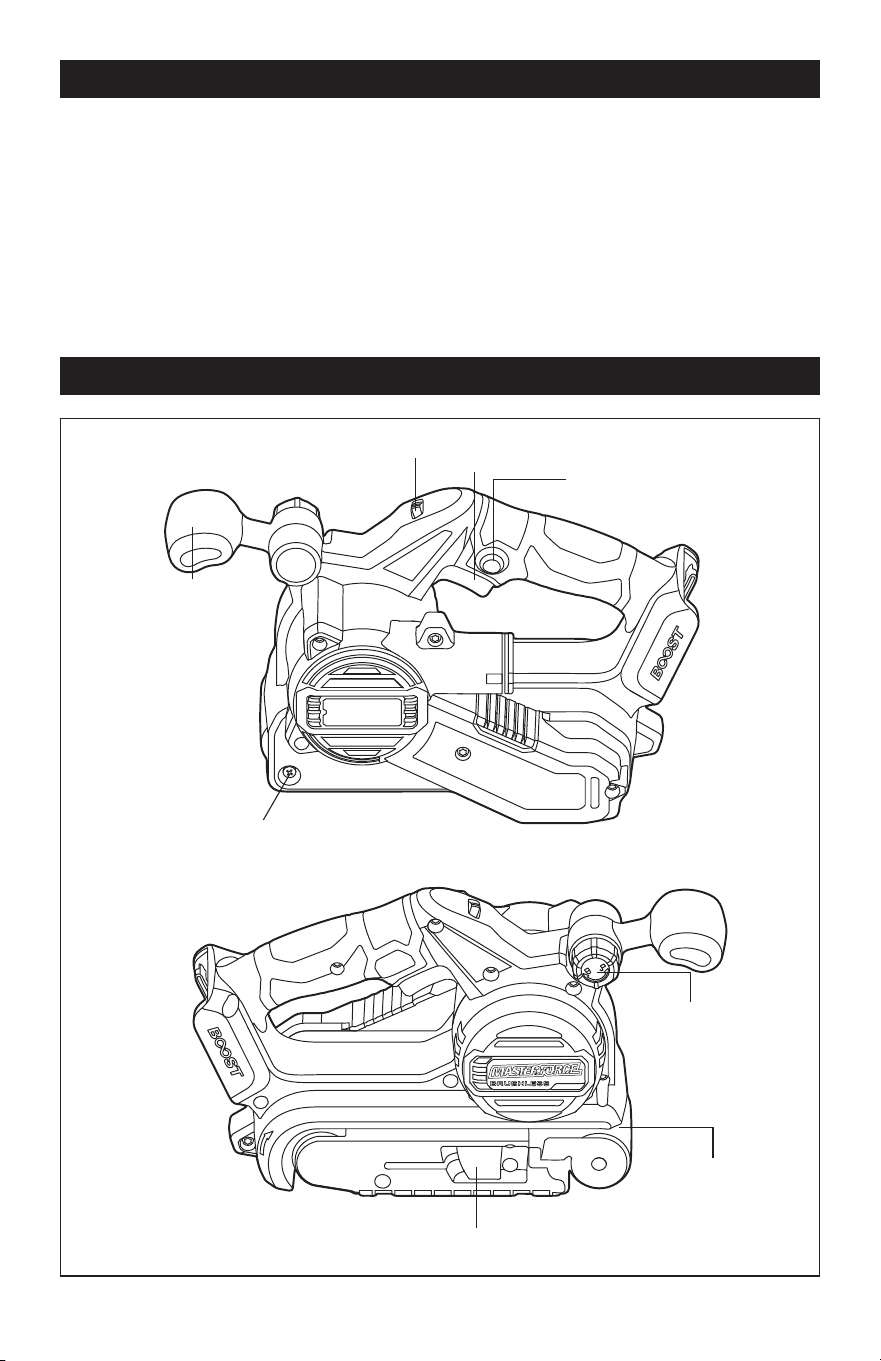
Variable-speed Dial
On/off Switch
Lock-on Button
Auxiliary
Handle
Locking Knob
Sanding Belt
Quick-release Tension Lever
Auxiliary Handle
Adjusting Screw
Page 8
SPECIFICATIONS
Rated voltage 20 V d.c. max
Variable speed 500 – 1100 SFPM (152 - 335 m/min)
Belt size 3’’ x 18" (7.6 x 45.7 cm)
Dust port size Ø 1-1/4” (3.2 cm)
Weight (without battery) 6 lbs. 2 oz. (2.77 kg)
ASSEMBLY
WARNING:
If any part is broken or
missing, DO NOT attach the battery pack
or operate the tool until the broken or
missing part is replaced. Failure to do so
could result in possible serious injury.
WARNING:
Do not attempt to
modify this tool or create accessories not
recommended for use with this tool. Any
such alteration or modification is misuse
and could result in a hazardous condition
leading to possible serious injury.
WARNING:
Your tool should
never be connected to the battery pack
when you are assembling parts, making
adjustments, cleaning, or when it is not in
use. Disconnecting the tool will prevent
accidental starting, which could cause
serious personal injury.
PACKING LIST
– Cordless belt sander
– Dust bag
– Sanding belt
– Operator’s manual
UNPACKING
1. Carefully remove the tool and any
accessories from the carton. Make sure
that all items listed in the packing list are
included.
2. Inspect the tool carefully to make sure
that no breakage or damage occurred
during shipping.
3. Do not discard the packing material
until you have carefully inspected and
satisfactorily operated the tool.
Page 9
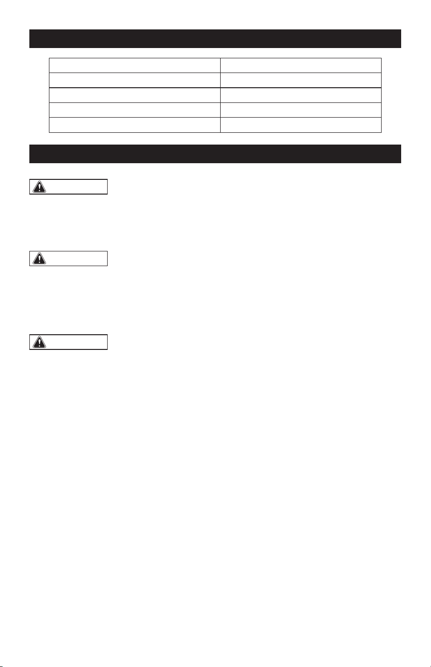
ATTACH THE BATTERY PACK
(FIG. 1)
FIG. 1
Battery-release Button
Attach
Detach
1. Make sure that the belt sander is turned
off.
2. Align the raised rib on the battery pack
with the groove on the bottom of the
belt sander, and then attach the battery
pack to the belt sander as shown in
FIG. 1.
DETACH THE BATTERY PACK
(FIG. 1)
1. Make sure that the belt sander is turned
off.
2. Depress the battery-release button
located on the front of the battery pack
to release the battery pack.
3. Pull the battery pack out from the tool.
INSTALL THE SANDING BELT
(FIG. 2)
FIG. 2
Quick-release
Tension Lever
Rotation
Direction Arrow
WARNING:
Always detach the
battery pack from the sander before
installing or removing sanding belt.
1. Detach the battery pack.
2. Place sander on its side and pull the
quick-release tension lever out, as
shown in FIG. 2.
3. Insert the new belt around both rollers.
Ensure the arrow on the inside of belt
is pointing in the direction of rotation as
indicated on housing.
4. Once the belt is centered over the rollers
and bottom plate, place quick-release
tension lever back in its original position
to restore belt tension.
REMOVE THE SANDING BELT
(FIG. 2)
1. Detach the battery pack.
2. Place the sander on its side and rotate
the quick-release tension lever away
from the sander, as shown in FIG. 2.
3. With the sander on its side and the open
side facing you, you can easily remove
the belt.
ADJUST THE BELT POSITION
Hold the product tight and press the on/off
switch then release it. The belt rotates for
a short period to be centered automatically
through the auto belt tracking system.
OPERATION
Page 10
OPERATION
Rotate the adjusting screw (FIG. 3) to ne
adjust the belt if necessary.
Rotate the adjusting screw counterclock-
wise and the sanding belt will travel toward
the sander. Rotate the adjusting screw
clockwise and the sanding belt will travel
away from the sander.
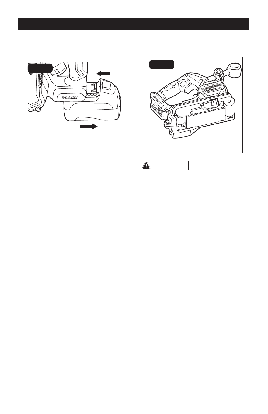
INSTALL THE DUST BAG (FIG. 3)
FIG. 3a
Rib
Collar
Dust Port
Zipper
FIG. 3b
Slot
1. Detach the battery pack from the
sander.
2. Align the slot in the dust bag’s collar
with the rib on the dust port, and then
push the dust bag onto the tool until it
locks into place.
REMOVE THE DUST BAG (FIG. 3)
1. Detach the battery pack from the
sander.
2. Pull the dust bag away from the dust
port.
NOTICE: Close the zipper on the dust bag
before operating the tool. The dust port on
the tool can also accept a 1 1/4” (3.2 cm)
vacuum hose or adapter for dust collection.
CLEAN THE DUST BAG (FIG. 3)
Check the dust bag frequently and empty
it before it gets full. To empty the dust bag,
remove it from the tool. Open the zipper on
the back side of the bag and empty the dust
into waste container.
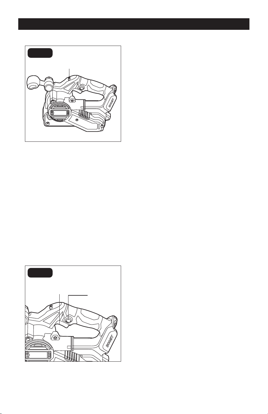
ADJUST THE ANGLE OF THE
AUXILIARY HANDLE (FIG. 4)
FIG. 4
Operating
Positions
Storage
Position
Auxiliary Handle Locking Knob
1. The auxiliary handle can be locked in
one of the 4 positions – storage position
and 3 operating positions.
2. Turn the auxiliary handle locking knob
counterclockwise to loosen the auxiliary
handle.
3. Place the auxiliary handle into one of the
three operating positions so that you
can hold the product safely, securely,
and comfortably during operation.
4. Turn the auxiliary handle locking knob
clockwise to secure the auxiliary handle.
Adjusting
Screw
Page 11
OPERATION
ADJUST THE SPEED (FIG. 5)
FIG. 5
The variable-speed feature on this sander
allows you to match the proper speed to the
material being sanded.
1. The variable-speed dial is used to adjust
the speed of the sander.
2. Turn the dial to increase or decrease the
speed of the tool.
3. Position the dial at “1” to select the
slowest speed; position the dial at “6”
to select the fastest speed. Adjust the
speed for optimum performance.
TURN THE SANDER ON AND OFF
(FIG. 6)
FIG. 6
The tool can be turned on or off by squeez-
ing or releasing the on/off switch.
LOCK-ON BUTTON (FIG. 6)
1. The tool is also equipped with a lock-on
button that allows continuous operation
without continually pressing the on/off
the switch.
2. To lock switch “ON”: squeeze the on/off
switch, depress the lock-on button, and
then release the on/off switch.
3. To unlock the switch: squeeze the
on/off switch, then release it without
depressing the lock-on button.
GENERAL SANDING
1. Be sure the battery pack is attached
to the sander rmly. Grasp the handles
rmly.
2. Start the sander off of the work surface
to avoid gouging the work surface with
the belt. NEVER start or stop the sander
with the belt in contact with the work
surface.
3. Place the heel of the sander on the
work surface rst. Then, with a forward
motion, begin the sanding stroke as the
tool is lowered onto the work surface.
4. Use short, overlapping strokes, moving
the sander slowly back and forth across
the work surface.
Variable-speed Dial
Lock-on
Button
On/off
Switch
Page 12
OPERATION
MAINTENANCE
5. Avoid tilting or rocking the sander or
sanding in one spot for too long. This
causes gashes and hollows in the
surface. Do not apply pressure to the
sander. The sander is the weighted
for the pressure needed. Too much
pressure will overload the motor and
reduce the belt speed.
6. Begin sanding with a coarser grit
sandpaper and gradually use ner grits,
until the desired nish is achieved. Do
not switch from a coarse grit to a very
ne grit in one step.
7. To stop, lift the sander from the work
surface, then turn the sander off.
Disengage the lock-on button. Allow
the sander to come to a complete stop
before setting it down. A moving belt will
cause the sander to “run away” even if
the motor is off.
WARNING:
• Before sanding small workpieces, ensure
the workpiece is securely held in a vise or
clamp.
• Sanding can produce clouds of fine dust
particles that can ignite in the presence of
sparks or an open flame. To avoid injury,
always use your sander in a well-ventilated
area.
• For your safety and to avoid damage,
turn the sander on and off only when the
sander is not in contact with a surface.
BEFORE EACH USE
Before cleaning or performing any
maintenance, make sure the sander has
been disconnected from the battery pack.
Keep all ventilation openings clean. Avoid
using solvents when cleaning plastic parts.
Most plastics are susceptible to damage
from various types of commercial solvents
and may be damaged by their use. Use a
clean cloth to remove dirt, oil and grease.
WARNING:
• Do not let brake fluids, gasoline,
petroleum-based products, penetrating oil,
etc., come into contact with plastic parts.
These substances contain chemicals that
can damage, weaken, or destroy plastic.
• To ensure safety and reliability, all repairs
should be performed by a qualified service
technician.

Page 13
PROBLEM POSSIBLE CAUSE SOLUTION
The sander does not
start.
Battery charge is depleted. Charge the battery.
Battery pack is too hot.
Turn off the tool and allow the
battery pack to cool under
airow.
Battery pack is not installed
properly.
Conrm that the battery pack is
locked and secured to the tool.
Unsatisfactory sanding
result.
The sanding belt is worn.
Replace with a new sanding
belt.
The sanding belt is not
suitable for the workpiece.
Use the correct sanding belt.
TROUBLESHOOTING

Page 14
PARTS LIST
No. Part Name No. Part Name
1 Tapping Screw 23 Hexagon Socket Screw
2 Decorative Cover 24 Aligning Plate
3 Belt Cover 25 Front Handle Cover
4 Timing Belt 26 Nut
5 Screw With Washer 27 Hexagon Nut
6 Small Belt Pulley 28 Front Handle
7 Left Housing Assembly 29 Compression Spring
8 Plain Washer 30 Plain Washer
9 Fan 31 Lock Knob
10 Fan Baffle 32 Mounting Assembly
11 Tapping Screw 33 Tapping Screw
12 Rotor Assembly 34 Front Pulley Assembly
13 Stator 35 Spring
14 L R Housing Set 36 Mounting Plate
15 Middle Housing Assembly 37 Mounting Cover
16 Screw 38 Lever
17 Spring 39 Hexagon Tapping Screw
18 Belt Control Assy 40 C Ring
19 Parallel Pin 41 O Ring
20 Plain Washer 301 Dust Bag Assembly
21 Tapping Screw 302 Belt Sanding Paper
22 Electric Assembly
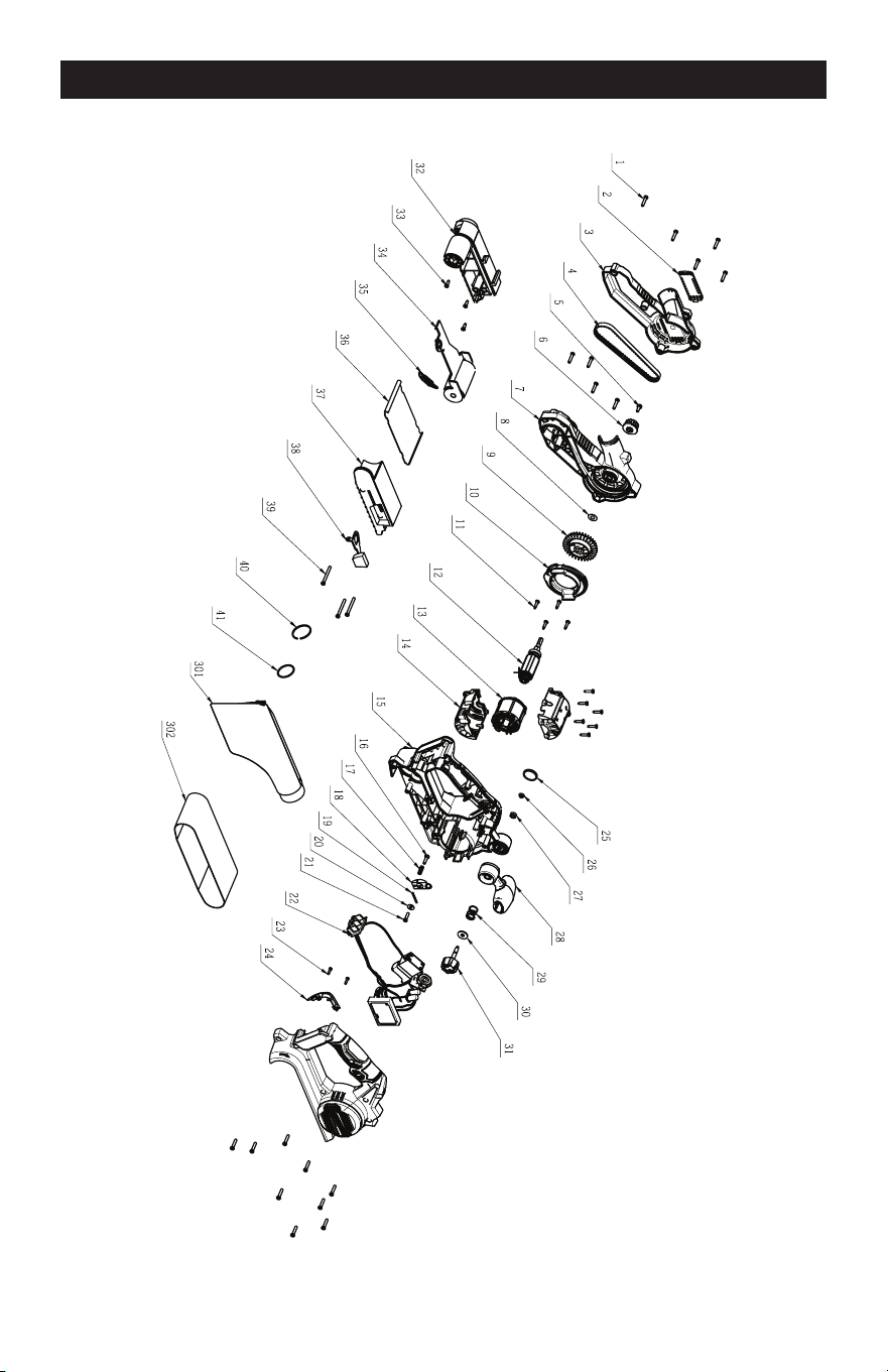
Page 15
SCHEMATIC DRAWING

Page 16
NOTES

Page 17
NOTES

3”x18’’ BELT SANDER

07/2024
© 2024 Menard, Inc., Eau Claire, WI 54703