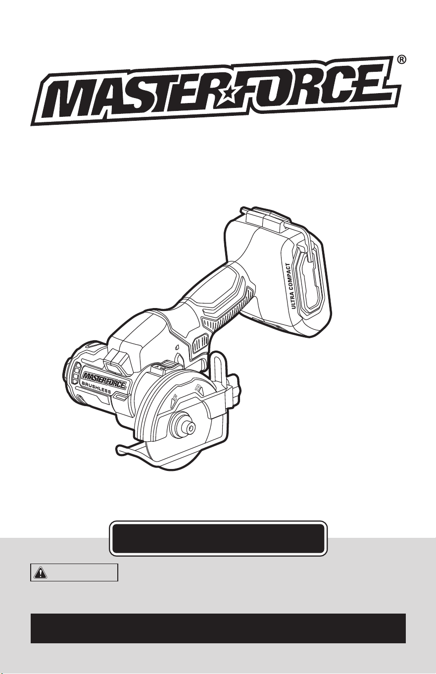
241-0349
OPERATOR’S MANUAL
CAUTION:
To Reduce the Risk of Injury, User Must
Read and Understand the Operator’s Manual. Save These
Instructions For Future Reference.
For questions / comments, technical assistance or repair parts –
Please Call Toll Free: 1-866-917-4374. (M-F 8:30am-5:00pm Est.)
3” CUT-OFF SAW

TABLE OF CONTENTS
Safety Symbols ......................................................... Page 2
Safety Instructions ...................................................... Page 3
Overview/Specications ................................................ Page 10
Assembly ............................................................ Page 11
Operation ............................................................ Page 11
Maintenance .......................................................... Page 20
Troubleshooting ....................................................... Page 21
Parts List ............................................................. Page 22
Schematic Drawing .................................................... Page 23
Warranty .............................................................Page 26
Page 2
SAFETY SYMBOLS
Some of these following symbols may be used on this tool. Please study them and learn their
meaning. Proper interpretation of these symbols will allow you to operate the tool better and
more safely.
Symbol
Name
Designation / Explanation
V Volts Voltage
A Amps Current
Hz Hertz Frequency (cycles per second)
W Watts Power
lbs Pounds Weight
n Rated speed Rotational speed at rated load
…/min
Revolutions or
Strokes per Minute
Revolutions, strokes, surface speed
orbits, etc., per minute
�
or d.c. Direct current Type of characteristic of current
Read instruction
manual
To reduce the risk of injury, user must
read instruction manual.
Wear eye protection
symbol
To reduce the risk of injury, always wear
eye protection.
Wear ear protection
symbol
To reduce the risk of injury, always wear
ear protection.
WARNING:
To ensure safety and reliability, all repairs should be performed by a
qualified service technician.
Page 3
SAFETY INSTRUCTIONS
The purpose of safety symbols is to attract your attention to possible dangers. The safety
symbols, and the explanations with them, deserve your careful attention and understand-
ing. The symbol warnings do not, by themselves, eliminate any danger. The instructions and
warnings they give are no substitutes for proper accident prevention measures.
WARNING:
Be sure to read and understand all safety instructions in this manual,
including all safety alert symbols such as “DANGER,” ”WARNING,” and “CAUTION”
before using this tool. Failure to follow all instructions listed below may result in electric
shock, fire, and/or serious personal injury.
SYMBOL MEANING
SAFETY ALERT SYMBOL: Indicates DANGER, WARNING, OR CAUTION.
May be used in conjunction with other symbols or pictographs.
DANGER:
Indicates an imminently hazardous situation, which, if not avoided,
will result in death or serious injury.
WARNING:
Indicates a potentially hazardous situation, which, if not avoided,
could result in death or serious injury.
CAUTION:
Indicates a potentially hazardous situation, which, if not avoided, could
result in minor or moderate injury.
NOTICE: (Without Safety Alert Symbol) Indicates a situation that may result in property
damage.
SAVE THESE INSTRUCTIONS!

Page 4
GENERAL POWER TOOL
SAFETY WARNINGS
WARNING:
Read all safety
warnings, instructions, illustrations and
specifications provided with this power
tool. Failure to follow all instructions listed
below may result in electric shock, re and/or
serious injury.
SAVE ALL WARNINGS AND INSTRUCTIONS
FOR FUTURE REFERENCE.
The term “power tool” in the warnings refers
to your mains-operated (corded) power tool
or battery-operated (cordless) power tool.
WORK AREA SAFETY
1. Keep work area clean and well lit.
Cluttered or dark areas invite accidents.
2. Do not operate power tools in explosive
atmospheres, such as in the presence of
flammable liquids, gases or dust. Power
tools create sparks which may ignite the
dust or fumes.
3. Keep children and bystanders away
while operating a power tool. Distractions
can cause you to lose control.
ELECTRICAL SAFETY
1. Power tool plugs must match the
outlet. Never modify the plug in any way.
Do not use any adapter plugs with earthed
(grounded) power tools. Unmodied plugs
and matching outlets will reduce risk of
electric shock.
2. Avoid body contact with earthed
or grounded surfaces, such as pipes,
radiators, ranges and refrigerators. There
is an increased risk of electric shock if your
body is earthed or grounded.
3. Do not expose power tools to rain or
wet conditions. Water entering a power tool
will increase the risk of electric shock.
4. Do not abuse the cord. Never use the
cord for carrying, pulling or unplugging the
power tool. Keep cord away from heat, oil,
sharp edges or moving parts. Damaged or
entangled cords increase the risk of electric
shock.
5. When operating a power tool outdoors,
use an extension cord suitable for outdoor
use. Use of a cord suitable for outdoor use
reduces the risk of electric shock.
6. If operating a power tool in a damp
location is unavoidable, use a ground fault
circuit interrupter (GFCI) protected supply.
Use of an GFCI reduces the risk of electric
shock.
PERSONAL SAFETY
1. Stay alert, watch what you are doing
and use common sense when operating a
power tool. Do not use a power tool while
you are tired or under the influence of
drugs, alcohol or medication. A moment of
inattention while operating power tools may
result in serious personal injury.
2. Use personal protective equipment.
Always wear eye protection. Protective
equipment such as a dust mask, non-skid
safety shoes, hard hat or hearing protection
used for appropriate conditions will reduce
personal injuries.
3. Prevent unintentional starting. Ensure
the switch is in the off-position before
connecting to power source and/or battery
pack, picking up or carrying the tool.
Carrying power tools with your nger on the
switch or energizing power tools that have
the switch on invites accidents.
4. Remove any adjusting key or wrench
before turning the power tool on. A wrench
or a key left attached to a rotating part of the
power tool may result in personal injury.
5. Do not overreach. Keep proper footing
and balance at all times. This enables better
control of the power tool in unexpected
situations.
SAFETY INSTRUCTIONS

Page 5
SAFETY INSTRUCTIONS
6. Dress properly. Do not wear loose
clothing or jewelry. Keep your hair and
clothing away from moving parts. Loose
clothes, jewelry or long hair can be caught
in moving parts.
7. If devices are provided for the
connection of dust extraction and
collection facilities, ensure these are
connected and properly used. Use of dust
collection can reduce dust-related hazards.
8. Do not let familiarity gained from
frequent use of tools allow you to become
complacent and ignore tool safety
principles. A careless action can cause
severe injury within a fraction of a second.
POWER TOOL USE AND CARE
1. Do not force the power tool. Use the
correct power tool for your application. The
correct power tool will do the job better and
safer at the rate for which it was designed.
2. Do not use the power tool if the switch
does not turn it on and off. Any power tool
that cannot be controlled with the switch is
dangerous and must be repaired.
3. Disconnect the plug from the power
source and/or remove the battery pack,
if detachable, from the power tool before
making any adjustments, changing
accessories, or storing power tools. Such
preventive safety measures reduce the risk
of starting the power tool accidentally.
4. Store idle power tools out of the reach
of children and do not allow persons
unfamiliar with the power tool or these
instructions to operate the power tool.
Power tools are dangerous in the hands of
untrained users.
5. Maintain power tools and accessories.
Check for misalignment or binding of
moving parts, breakage of parts and any
other condition that may affect the power
tool’s operation. If damaged, have the power
tool repaired before use. Many accidents are
caused by poorly maintained power tools.
6. Keep cutting tools sharp and clean.
Properly maintained cutting tools with sharp
cutting edges are less likely to bind and are
easier to control.
7. Use the power tool, accessories
and tool bits etc. in accordance with
these instructions, taking into account
the working conditions and the work to
be performed. Use of the power tool for
operations different from those intended
could result in a hazardous situation.
8. Keep handles and grasping surfaces
dry, clean and free from oil and grease.
Slippery handles and grasping surfaces do
not allow for safe handling and control of the
tool in unexpected situations.
BATTERY TOOL USE
AND CARE
1. Recharge only with the charger
specified by the manufacturer. A charger
that is suitable for one type of battery pack
may create a risk of re when used with
another battery pack.
2. Use power tools only with specifically
designated battery packs. Use of any other
battery packs may create a risk of injury and
re.
3. When battery pack is not in use, keep
it away from other metal objects, like
paper clips, coins, keys, nails, screws or
other small metal objects, that can make
a connection from one terminal to another.
Shorting the battery terminals together may
cause burns or a re.
4. Under abusive conditions, liquid may
be ejected from the battery; avoid contact.
If contact accidentally occurs, flush with
water. If liquid contacts eyes, additionally
seek medical help. Liquid ejected from the
battery may cause irritation or burns.
5. Do not use a battery pack or tool that is
damaged or modified. Damaged or modied
batteries may exhibit unpredictable behavior
resulting in re, explosion or risk of injury.

Page 6
SAFETY INSTRUCTIONS
6. Do not expose a battery pack or tool
to fire or excessive temperature. Exposure
to re or temperature above 265 °F (130 °C)
may cause explosion.
7. Follow all charging instructions and
do not charge the battery pack or tool
outside the temperature range specified
in the instructions. Charging improperly or
at temperatures outside the specied range
may damage the battery and increase the
risk of re.
SERVICE
1. Have your power tool serviced by a
qualified repair person using only identical
replacement parts. This will ensure that the
safety of the power tool is maintained.
2. Never service damaged battery
packs. Service of battery packs should
only be performed by the manufacturer or
authorized service providers.
SAFETY INSTRUCTIONS FOR
ABRASIVE CUTTING-OFF
OPERATIONS
CUTTING-OFF MACHINE SAFETY
WARNINGS
1. The guard provided with the tool must
be securely attached to the power tool
and positioned for maximum safety, so
the least amount of wheel is exposed
towards the operator. Position yourself
and bystanders away from the plane of the
rotating wheel. The guard helps to protect
operator from broken wheel fragments and
accidental contact with wheel.
2. Use only bonded reinforced or diamond
cut-off wheels with your power tool. Just
because an accessory can be attached to
your power tool, it does not assure safe
operation.
3. The rated speed of the accessory must
be at least equal to the maximum speed
marked on the power tool. Accessories
running faster than their rated speed can
break and y apart.
4. Wheels must be used only for
recommended applications. For example:
do not grind with the side of cut-off wheel.
Abrasive cut-off wheels are intended for
peripheral grinding, side forces applied to
these wheels may cause them to shatter.
5. Always use undamaged wheel flanges
that are of correct diameter for your
selected wheel. Proper wheel anges
support the wheel thus reducing the
possibility of wheel breakage.
6. Do not use worn down reinforced
wheels from larger power tools. Wheels
intended for a larger power tool are not
suitable for the higher speed of a smaller
tool and may burst.
7. The outside diameter and the thickness
of your accessory must be within the
capacity rating of your power tool.
Incorrectly sized accessories cannot be
adequately guarded or controlled.
8. The arbor size of wheels and flanges
must properly fit the spindle of the power
tool. Wheels and anges with arbor holes
that do not match the mounting hardware
of the power tool will run out of balance,
vibrate excessively and may cause loss of
control.
9. Do not use damaged wheels. Before
each use, inspect the wheels for chips
and cracks. If power tool or wheel is
dropped, inspect for damage or install an
undamaged wheel. After inspecting and
installing the wheel, position yourself and
bystanders away from the plane of the
rotating wheel and run the power tool at
maximum no load speed for one minute.
Damaged wheels will normally break apart
during this test time.

Page 7
10. Wear personal protective equipment.
Depending on application, use face
shield, safety goggles or safety glasses.
As appropriate, wear dust mask, hearing
protectors, gloves and shop apron capable
of stopping small abrasive or workpiece
fragments. The eye protection must be
capable of stopping ying debris generated
by various operations. The dust mask or
respirator must be capable of ltrating
particles generated by your operation.
Prolonged exposure to high intensity noise
may cause hearing loss.
11. Keep bystanders a safe distance away
from work area. Anyone entering the
work area must wear personal protective
equipment. Fragments of workpiece or of a
broken wheel may y away and cause injury
beyond immediate area of operation.
12. Hold the power tool by insulated
gripping surfaces only, when performing
an operation where the cutting accessory
may contact hidden wiring. Cutting
accessory contacting a “live” wire may
make exposed metal parts of the power tool
“live” and could give the operator an electric
shock.
13. Never lay the power tool down until the
accessory has come to a complete stop.
The spinning wheel may grab the surface
and pull the power tool out of your control.
14. Do not run the power tool while
carrying it at your side. Accidental contact
with the spinning accessory could snag your
clothing, pulling the accessory into your
body.
15. Regularly clean the power tool’s
air vents. The motor’s fan will draw the
dust inside the housing and excessive
accumulation of powdered metal may cause
electrical hazards.
16. Do not operate the power tool near
flammable materials. Sparks could ignite
these materials.
SAFETY INSTRUCTIONS
FURTHER SAFETY INSTRUC-
TIONS FOR ABRASIVE CUT-
TING-OFF OPERATIONS
KICKBACK AND RELATED WARNINGS
Kickback is a sudden reaction to a
pinched or snagged rotating wheel.
Pinching or snagging causes rapid
stalling of the rotating wheel which in
turn causes the uncontrolled power tool
to be forced in the direction opposite of
the wheel’s rotation at the point of the
binding.
For example, if an abrasive wheel is
snagged or pinched by the workpiece,
the edge of the wheel that is entering
into the pinch point can dig into the
surface of the material causing the
wheel to climb out or kick out. The wheel
may either jump toward or away from
the operator, depending on direction
of the wheel’s movement at the point
of pinching. Abrasive wheels may also
break under these conditions.
Kickback is the result of power tool
misuse and/or incorrect operating
procedures or conditions and can be
avoided by taking proper precautions as
given below.
1. Maintain a firm grip on the power
tool and position your body and arm
to allow you to resist kickback forces.
Always use auxiliary handle, if provided,
for maximum control over kickback or
torque reaction during start-up. The
operator can control torque reactions or
kickback forces, if proper precautions
are taken.
2. Never place your hand near the
rotating accessory. Accessory may
kickback over your hand.
3. Do not position your body in line
with the rotating wheel. Kickback will
propel the tool in direction opposite to
the wheel’s movement at the point of
snagging.
Page 8
SAFETY INSTRUCTIONS
4. Use special care when working
corners, sharp edges etc. Avoid bouncing
and snagging the accessory. Corners,
sharp edges or bouncing have a tendency to
snag the rotating accessory and cause loss
of control or kickback.
5. Do not attach a saw chain, woodcarving
blade, segmented diamond wheel with
a peripheral gap greater than 10 mm or
toothed saw blade. Such blades create
frequent kickback and loss of control.
6. Do not “jam” the wheel or apply
excessive pressure. Do not attempt
to make an excessive depth of cut.
Overstressing the wheel increases the
loading and susceptibility to twisting or
binding of the wheel in the cut and the
possibility of kickback or wheel breakage.
7. When wheel is binding or when
interrupting a cut for any reason, switch
off the power tool and hold the power
tool motionless until the wheel comes to
a complete stop. Never attempt to remove
the wheel from the cut while the wheel is
in motion otherwise kickback may occur.
Investigate and take corrective action to
eliminate the cause of wheel binding.
8. Do not restart the cutting operation
in the workpiece. Let the wheel reach full
speed and carefully re-enter the cut. The
wheel may bind, walk up or kickback if the
power tool is restarted in the workpiece.
9. Support panels or any oversized
workpiece to minimize the risk of wheel
pinching and kickback. Large workpieces
tend to sag under their own weight. Supports
must be placed under the workpiece near
the line of cut and near the edge of the
workpiece on both sides of the wheel.
10. Use extra caution when making a
“pocket cut” into existing walls or other
blind areas. The protruding wheel may
cut gas or water pipes, electrical wiring or
objects that can cause kickback.
IMPORTANT SAFETY
INSTRUCTIONS
1. To reduce the risk of electric shock or
damage to the chargers and batteries, use
only with the MASTERFORCE
®
20V battery
packs and chargers listed.
Battery pack Charger
252-8029 (1.5Ah)
252-8030 (2.5Ah)
252-8031 (2.0Ah)
252-8003 (2.5Ah)
252-8034 (4.0Ah)
252-8013 (4.0Ah)
252-8035 (5.0Ah)
252-8005 (5.0Ah)
252-8007 (7.5Ah)
252-8014 (8.0Ah)
252-8025
252-8037
252-8026
252-8043
2. For best results, your battery and tool
should be stored, charged and used in a
location where the temperature is more
than 41°F (5°C) but less than 104°F (40°C).
Do not store outside or in vehicles.
NOTE: The battery pack and charger
manuals are provided separately. They
include specic safety rules and operating
instructions. Please refer to the battery
pack and charger manuals for safety rules
and detailed operating instructions.
DANGER:
People with electronic
devices, such as pacemakers, should
consult their physician(s) before using
this product. Operation of electrical
equipment in close proximity to a heart
pacemaker could cause interference or
failure of the pacemaker.

Page 9
WARNING:
Drilling, sawing,
sanding or machining wood products can
expose you to wood dust, a substance
known to the State of California to cause
cancer. Avoid inhaling wood dust or use a
dust mask or other safeguards for personal
protection. For more information go to
www.P65Warnings.ca.gov/wood.
WARNING:
Some dust created by
power sanding, sawing, grinding, drilling,
and other construction activities contains
chemicals known to the state of California
to cause cancer, birth defects, or other
reproductive harm. Some examples of
these chemicals are:
Lead from lead-based paints.
Crystalline silica from bricks, cement,
and other masonry products.
Arsenic and chromium from chemically-
treated lumber.
SAFETY INSTRUCTIONS
Your risk from these exposures varies,
depending upon how often you do this type
of work. To reduce your exposure to these
chemicals:
Work in a well-ventilated area.
Work with approved safety equipment,
such as dust masks that are specially
designed to lter out microscopic particles.
Avoid prolonged contact with dust from
power sanding, sawing, grinding, drilling,
and other construction activities. Wear
protective clothing and wash exposed
areas with soap and water. Allowing dust
to get into your mouth or eyes or to lie on
the skin may promote absorption of harmful
chemicals.
SAVE THESE INSTRUCTIONS!
Page 10
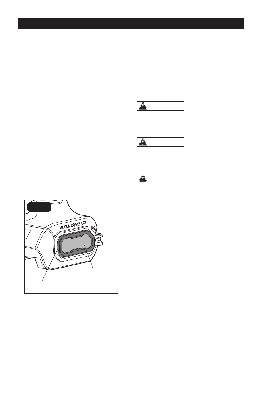
OVERVIEW
Handle
4mm Hex Key
Air-inlet Filter
Foot-locking Knob
Wheel Guard
LED Work
Light
Spindle-lock
Button
Lock-off Button
Variable-speed
Trigger Switch
Foot
Direction-of-
Rotation Selector
Direction-of-Rotation Indicator
Diamond Tile
Cut-off Wheel
Metal Cut-off
Wheel
SPECIFICATIONS
Rated Voltage 20 V d.c.
Rated Speed 20,000/min (RPM)
Wheel Diameter 3” (76 mm)
Arbor Size 3/8” (9.5 mm)
Max Cutting Depth 3/4” (19 mm)
Guard Pivot Range 0°, 15°, 30°, 45°
Maximum Wheel Thickness 7/64” (2.8 mm)
Weight (without battery) 2 lbs. 1 oz. (0.95 kg)
Page 11
OPERATION
ASSEMBLY
WARNING:
If any part is broken or
missing, DO NOT attach the battery pack
or operate the tool until the broken or
missing part is replaced. Failure to do so
could result in possible serious injury.
WARNING:
Do not attempt to
modify this tool or create accessories not
recommended for use with this tool. Any
such alteration or modication is misuse
and could result in a hazardous condition
leading to possible serious injury.
WARNING:
Your tool should
never be connected to the battery pack
when you are assembling parts, making
adjustments, cleaning, or when it is not in
use. Disconnecting the tool will prevent
accidental starting, which could cause
serious personal injury.
PACKING LIST
Cut-off saw, diamond tile cut-off wheel,
metal cut-off wheel, hex key (attached to the
tool) and instruction manual.
UNPACKING
1. Carefully remove the tool and any
accessories from the carton. Make sure
that all items listed in the packing list are
included.
2. Inspect the tool carefully to make sure
that no breakage or damage occurred
during shipping.
3. Do not discard the packing material
until you have carefully inspected and
satisfactorily operated the tool.
ATTACH THE BATTERY PACK
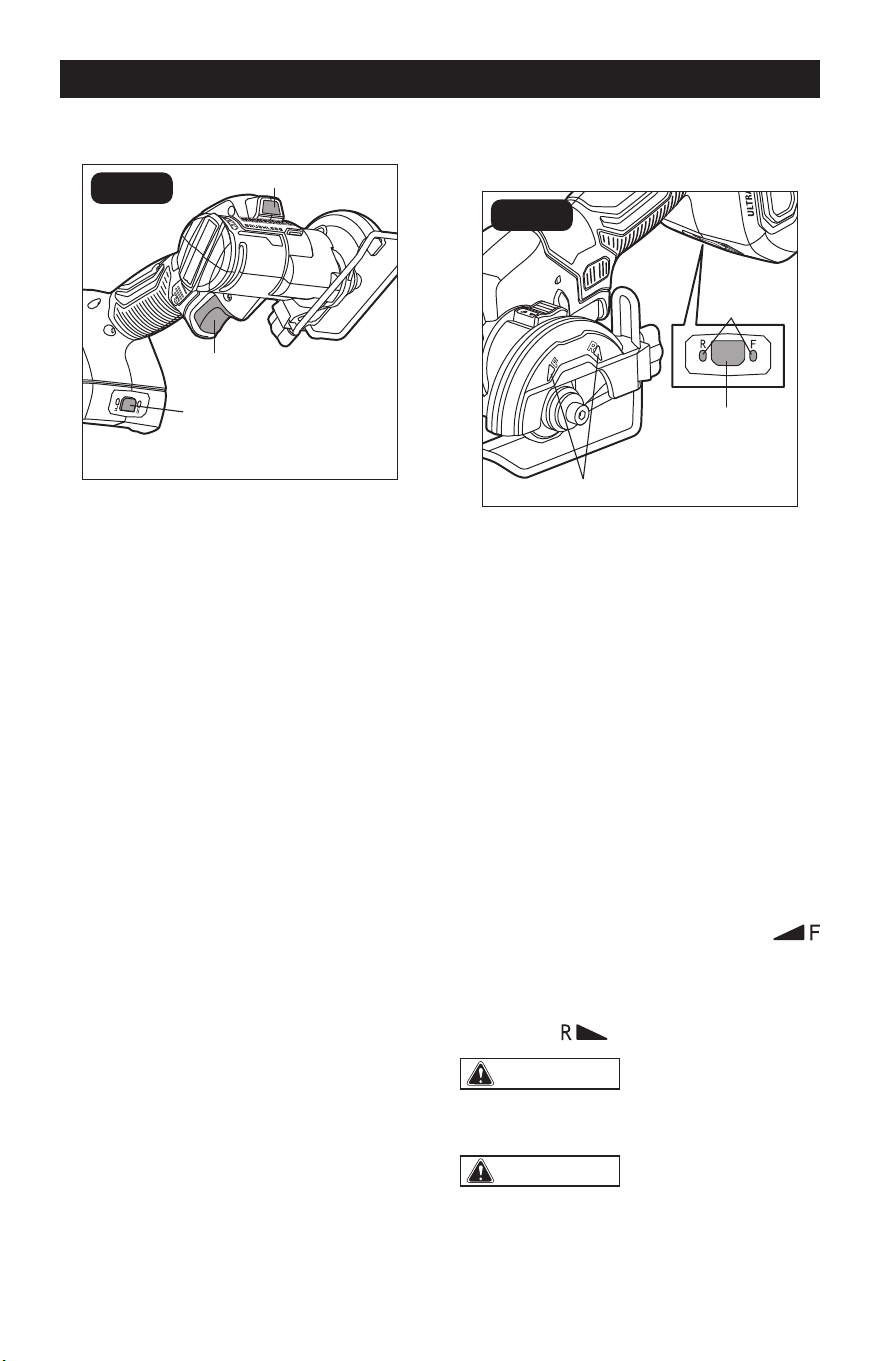
(FIG. 1)
FIG. 1
Attach
Detach
Battery-release Button
1. Lock the variable-speed trigger switch
in the OFF position (refer to the section
“LOCK-OFF BUTTON”).
2. Align the raised ribs on the battery pack
with the grooves in the tool, and then
slide the battery pack onto the tool.
3. Make sure that the latch on the battery
pack snaps into place, and that the
battery pack is attached securely to the
tool before beginning operation.
DETACH THE BATTERY PACK
(FIG. 1)
1. Lock the trigger switch in the OFF
position.
2. Depress the battery-release button,
located on the front of the battery pack,
to release the battery pack.
3. Pull the battery pack out and remove it
from the tool.
Page 12
OPERATION
LED WORK LIGHT (FIG. 2)
FIG. 2
LED Work Light
Direction-of-
Rotation Selector
Variable-speed
Trigger Switch
The LED work light, located in the head of
the tool, will illuminate when the variable-
speed trigger switch or the direction-of-
rotation selector is depressed without
turning the tool on. This provides additional
illumination of the surface of the workpiece.
The LED work light will turn off approximately
10 seconds after the variable-speed trigger
switch is released.
The LED work light will ash rapidly when
the tool and/or battery pack becomes
overloaded or too hot and the internal
sensors will turn the tool off. Rest the tool
for a while or place the tool and battery pack
separately under air ow for cooling.
The LED work light will ash slowly to
indicate that the battery charge is very low.
Charge the battery pack.
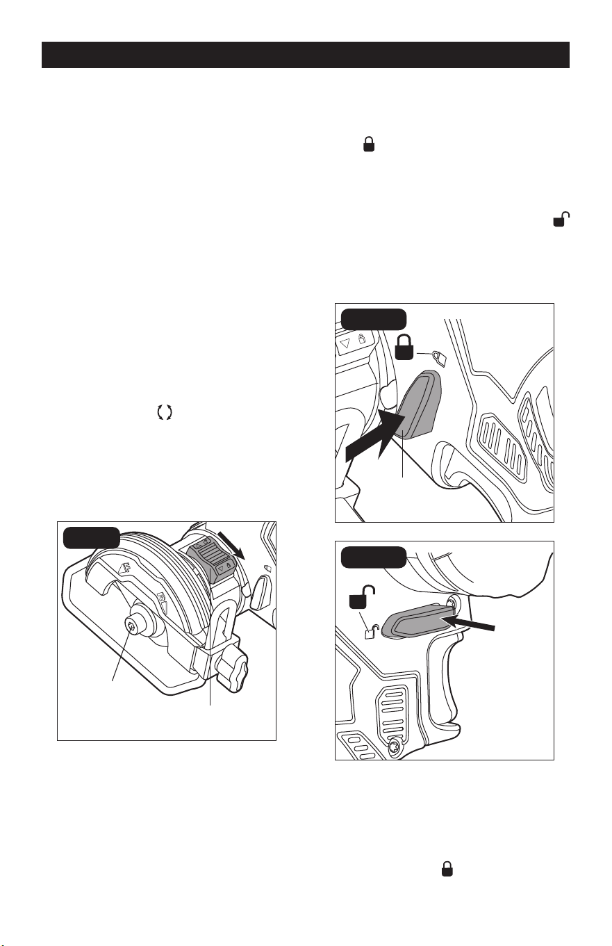
DIRECTION-OF-ROTATION
SELECTOR (FIG. 3)
FIG. 3
Marks
Direction-
of-Rotation
Selector
Direction-
of-Rotation
Indicator
This tool has two rotation directions –
forward and reverse. Choose the direction
depending on the cut you are trying to make.
1. Attach the battery pack.
2. Depress the trigger switch or direction-
of-rotation selector to “wake up” the
direction-of-rotation indicators.
3. Press the direction-of-rotation selector
to select the direction. Every time you
press the selector, the direction of
rotation will be switched. The direction-
of-rotation indicator will illuminate to
indicate the active direction of rotation.
If you choose “F” (Forward), the cut-off
wheel will rotate COUNTERCLOCKWISE
in the direction of wheel rotation
marked on the guard. If you choose “R”
(Reverse), the cut-off wheel will rotate
CLOCKWISE in the direction of wheel
rotation marked on the guard.
WARNING:
Lock the lock-off
button in the OFF position to help prevent
accidental starting when not in use.
WARNING:
When cutting metal,
it is not recommended to choose “F”
direction. Sparks generated during cutting
will direct towards your body, which may
cause serious injury.
Page 13
OPERATION
NOTICE: To prevent damage, always
allow the wheel to come to a complete stop
before changing the direction of rotation.
NOTE: The direction-of-rotation
indicator will turn off within approximately
10 seconds after the trigger switch or
direction-of-rotation selector is released,
and will revert to the previous setting when
the tool is turned on again.
NOTE: The wheels provided with this
tool have arrows, indicating the direction
the wheels should rotate when the tool
is in use. Before operating the tool make
sure the direction-of-rotation selector is
in the position that matches the direction
of rotation marked on the wheel, refer to
the section “DIRECTION-OF-ROTATION
SELECTOR” section. Wheels with
bidirectional arrows can be operated in
either forward or reverse direction.
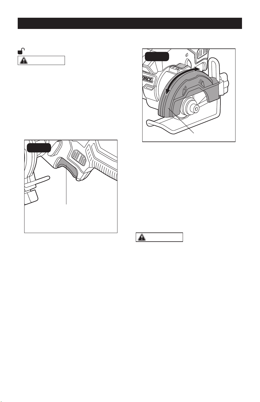
SPINDLE-LOCK BUTTON
(FIG. 4)
FIG. 4
Spindle
Spindle-lock
Button
You need to lock the spindle when installing/
removing the cut-off wheel and unlock the
spindle before switching on the tool.
To Lock the Spindle
Rotate the spindle while pushing the
spindle-lock button downwards to the
locked
position until you hear a “click”
and hold it in down position.
To Unlock the Spindle
Release the spindle-lock button and the
button will return to the unlocked
position.
LOCK-OFF BUTTON (FIG. 5)
FIG. 5a
Lock-off
Button
FIG. 5b
Your tool is equipped with a lock-off
button, a safety feature, to prevent the tool
from being activated unintentionally.
To lock the trigger switch in the OFF
position, depress the lock-off button from
the side marked with
(FIG. 5a).
Page 14
OPERATION
To unlock the trigger switch, depress the
lock-off button from the side marked with
(FIG. 5b).
WARNING:
Battery tools are
always in operating condition. ALWAYS
lock the trigger switch in the OFF position
when the tool is not in use, or before
making any assembly, adjustments, or
changing accessories.
VARIABLE-SPEED TRIGGER
SWITCH (FIG. 6)
FIG. 6
Variable-speed
Trigger Switch
Your tool is equipped with a variable-speed
trigger switch. The tool can be turned “ON”
or “OFF” by depressing or releasing the
trigger.
The variable-speed trigger switch delivers
higher speed with increased trigger pressure
and lower speed with decreased trigger
pressure.
PIVOTING THE GUARD (FIG. 7)
FIG. 7
Wheel Guard
The wheel guard on the tool should be
correctly pivoted to provide maximum
protection to the operator. Never use the
tool without the guard correctly in place.
1. Remove the battery pack.
2. Get a rm grasp of the guard with one
hand and hold the handle with the other.
3. Rotate the guard until you hear a “click”.
It can be secured into one of four xed
positions (0°, 15°, 30°, 45°).
WARNING:
Do not force the
tool when making a cut. Excessive force
applied to the tool may unexpectedly pivot
the guard, which will result in compromised
protection of the operator and create a risk
of injury.
Page 15
3. Remove the assembly and store it in a
safe place for future use.
CUT-OFF WHEEL SELECTION
Selecting the correct type of wheel is
important in order to obtain the best
performance from the tool. Select the wheel
based on the application and on the material
you wish to cut. Selecting the right wheel will
give you a smoother, faster cut and prolong
the life of the wheel.
The best of cut-off wheels will not cut
efciently if they are not kept clean and
sharp. Using a dull wheel will place a heavy
load on the tool and increase the danger of
kickback. Keep extra wheels on hand, so
that sharp wheels are always available.
Always carefully select and use cut-off wheels
that are recommended for the material being
cut. Make sure that the minimum operating
speed of any accessory wheel selected is
20,100 /min (RPM) or more.
WARNING:
Never use grinding
wheels of any kind with this tool. Use of
non-cutting wheels can result in serious
personal injury or property damage.
Refer to the table below to select a suitable
cut-off wheel and set recommended
direction of rotation.
ADJUSTING THE FOOT
ASSEMBLY (FIG. 8)
a
b
FIG. 8
Foot-locking Knob
Foot
This tool is equipped with an adjustable foot
to meet different needs.
1. Remove the battery pack.
2. Hold the foot with one hand
and turn the foot-locking knob
COUNTERCLOCKWISE to loosen the
assembly with the other, until the foot
moves freely.
3. Adjust the foot to the desired height and
tighten it by turning the locking knob
CLOCKWISE.
To Remove the Foot
1. Remove the battery pack.
2. Hold the foot with one hand and turn the
locking knob COUNTERCLOCKWISE
with the other, to loosen the assembly.
OPERATION
Page 16
OPERATION
CUT-OFF WHEEL APPLICATIONS
Carbide
Abrasive Cut-
off Wheel (not
included)
Cutting drywall, plastic.
Recommended direction of rotation:
1. R for push cut
2. F for pull cut
Metal Cut-off
Wheel
Cutting steel, stainless steel, non-ferrous materials.
Recommended direction of rotation:
1. R for push cut
2. F for pull cut*
*Tool can throw sparks towards user, proceed with
caution!
Diamond Tile
Cut-off Wheel
Cutting tile, ceramics, ber cement.
Recommended direction of rotation: The arrow on the
wheel indicates the ONLY direction the wheel should
rotate when the tool is in use. Always make sure the
direction of rotation selector is in the position that
matches the direction of rotation marked on the wheel.
The diamond grit on the wheel will be eaten up quickly
if the wheel is rotating in the wrong direction during
cutting.
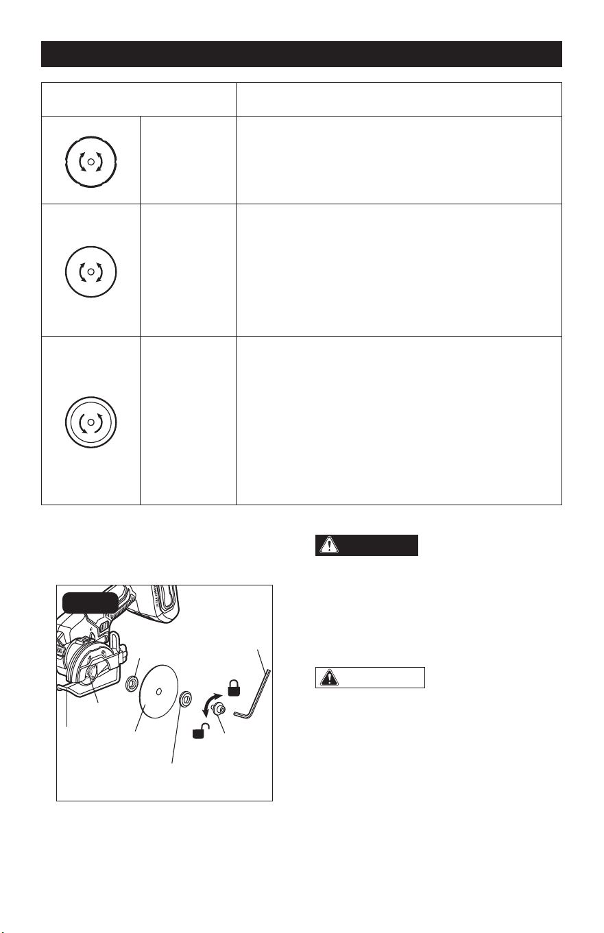
TO INSTALL/REMOVE THE CUT-
OFF WHEEL (FIG. 9)
FIG. 9
Foot
Spindle
Cut-off
Wheel
Bolt with
Washer
Hex Key
Inner Flange
(large diameter
faces wheel)
Outer Flange
(large diameter
faces wheel)
DANGER:
Use ONLY type 41
wheels or diamond cut-off wheels (such
as the ones provided with this product).
Never attach a Type 27 grinding wheel
to this tool. Use for any other purpose is
not recommended and creates a hazard,
which will result in serious injury.
WARNING:
A 3 in. wheel is the
maximum wheel capacity of the tool. Never
use a wheel that is too thick to allow outer
ange to engage with the ats on the
spindle. Larger cut-off wheels will come in
contact with the wheel guard, while thicker
wheels will prevent the shaft bolt from
securing the wheel on the spindle. Either
of these situations could result in a serious
injury.
Page 17
OPERATION
WARNING:
To reduce the risk of
injury, only use the proper wheels made
for this tool. Never use any type of toothed
saw blade.
WARNING:
Remove the battery
pack from the tool before making any
assembly, adjustments, or changing
accessories. Such preventive safety
measures reduce the risk of starting the
tool accidentally.
To Install the Cut-off Wheel
1. Remove the battery pack.
2. Select an appropriate cut-off wheel
(refer to the section “CUT-OFF WHEEL
SELECTION”).
3. Lock the spindle (refer to the section
“SPINDLE-LOCK BUTTON”). Then
loosen the bolt COUNTERCLOCKWISE
with the provided hex key.
4. Remove the bolt with washer, and the
outer ange. Keep the inner ange on
the spindle.
5. Fit the cut-off wheel onto the spindle
from the underside of the foot.
6. Reinstall the outer ange and make sure
that the larger diameter is facing the
wheel.
7. Lock the spindle rst, then tighten the
bolt CLOCKWISE with the hex key.
NOTICE: The wheels provided with this
tool are marked with arrows, indicating the
direction the wheels should rotate when
the tool is in use. Before operating the
tool, make sure the direction-of-rotation
selector is in the appropriate position, refer
to the section “DIRECTION-OF-ROTATION
SELECTOR”. Wheels with bidirectional
arrows
can be operated in either forward
or reverse.
WARNING:
Always operate the tool
in the direction of rotation that matches the
installed wheel.
To Remove the Cut-off Wheel
1. Remove the battery pack.
2. Lock the spindle, then loosen the
bolt COUNTERCLOCKWISE with the
provided hex key.
3. Remove the bolt with washer, and the
outer ange.
4. Remove the cut-off wheel.
OVERLOAD PROTECTION
When the tool is forced or the motor is
overloaded, the tool will automatically shut
off. To reset the tool, release the trigger and
restart operation. Do not force the tool.
ELECTRIC BRAKE
The cut-off saw is equipped with an electric
brake. When the trigger switch is released,
the electric brake engages automatically to
quickly stop the cut-off wheel rotation.
OPERATING THE TOOL
DANGER:
Never use the tool with
the guard removed. It has been designed
for use only with the guard installed.
Attempting to use tool with the guard
removed will result in loose particles
being thrown against the operator
resulting in serious personal injury.
WARNING:
To make cutting easier
and safer, always maintain proper control
of the tool. Loss of control could cause an
accident resulting in possible serious injury.
WARNING:
Beware of the exposed
blade. When lifting the tool from the
workpiece, the wheel is exposed on the
underside of the tool.
1. Remove the battery pack.
2. Install the appropriate cut-off wheel.
Page 18
3. Adjust the foot up or down to set the
depth of cut or remove it completely if
needed.
4. Rotate the wheel guard to provide
maximum protection for the operator.
5. Secure the workpiece to a work bench
or table with a vise or clamps.
6. Mark the line of cut clearly.
7. Install the battery pack.
8. Check the direction of rotation marked on
the wheel and select the correct setting
with the direction-of-rotation selector.
9. Hold the tool rmly in front of and clearly
away from you, keeping the cut-off
wheel clear of the workpiece.
10. Unlock the lock-off button, depress the
trigger and let the cut-off wheel reach
full speed.
WARNING:
The wheel coming
in contact with the workpiece before
it reaches full speed could cause tool
to “kickback” toward you resulting in
serious injury.
11. Move the wheel through the workpiece.
NOTE: Do not force. Use only enough
pressure to keep the tool cutting. Let the
speed of the tool do the work.
12. Continue to use steady and even
pressure to obtain a uniform cut through
the material. Never force the wheel into
the material being cut.
13. When the cut is complete, release the
trigger and allow the wheel to stop
rotating before raising the wheel out of
material.
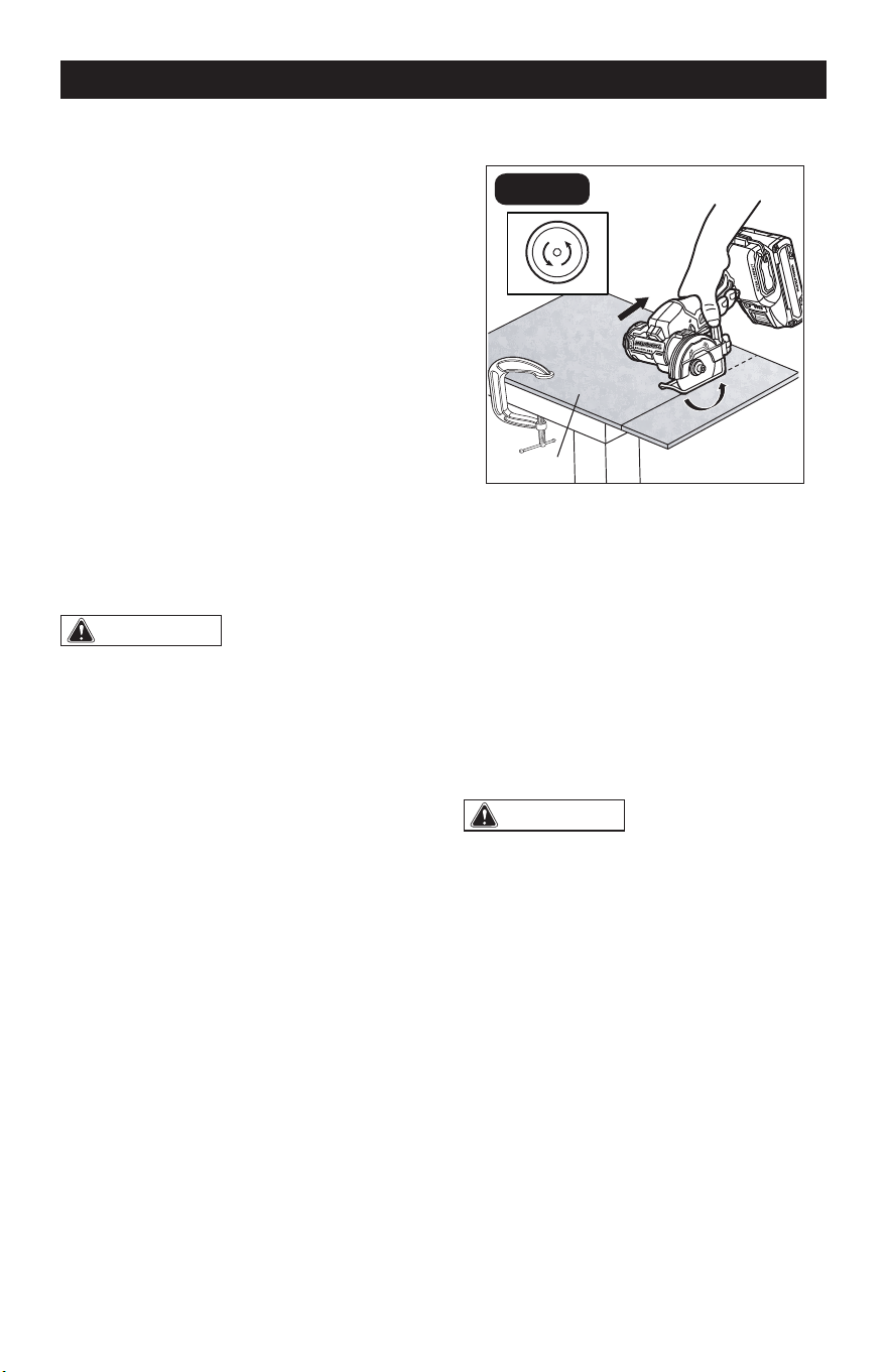
CUTTING TILES (FIG. 10a)
FIG. 10a
Tile
Pull
“F” Rotation
Always draw the line to be cut on the tile
using a marker or grease pencil. If the tile
is glossy and hard-to-mark, place masking
tape on the tile and mark the tape.
A common problem when cutting tile is
straying from the marked line. Once you’ve
strayed from the mark, do not force the
wheel back to the line by twisting the tile.
Instead, back up and recut the tile slicing off
a small amount of tile until the wheel is back
on track.
WARNING:
Sparks generated
during operation may cause personal
injury. Always wear protective equipment.
NOTICE: The arrow on the diamond wheel
indicates the ONLY direction the wheel
should rotate when the tool is in use. The
diamond grit on the wheel will be eaten
up quickly if the wheel is rotating in the
wrong direction during cutting. Always
make sure the direction-of-rotation
selector is in the position that matches
the direction of rotation marked on the
wheel.
OPERATION
Page 19
OPERATION
CUTTING PLASTICS (FIG. 10b)
FIG. 10b
Push
“R” Rotation
Plastic Pipe
With the carbide abrasive cut-off wheel
installed, you may cut plastics and drywall.
It is recommended to set the direction of
rotation to “R” when using push cutting
operation.
Heat generated from the cut-off wheel can
melt plastic. Follow these steps to reduce
the risk of overheating the cut-off wheel:
1. Cut slowly and do not force the wheel
into the material. Maintain a speed and
pressure which allows cutting without
overheating the wheel.
2. Take frequent breaks when cutting
plastic materials and allow the cut-off
wheel to cool.
NOTE: When cutting a PVC pipe, you can
also set the direction of rotation to “F” and
pull back the tool to finish your job.
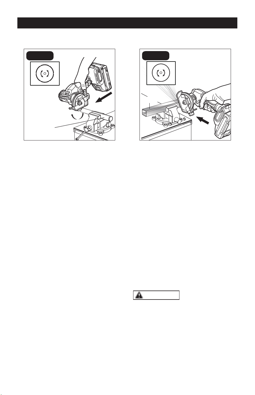
CUTTING METALS (FIG. 10c)
FIG. 10c
“R” Rotation
Metal Bar
Push
With a metal cut-off wheel installed, you
may cut metals such as sheet steel, pipe,
steel rods, aluminum, brass, and copper.
It is recommended to set the direction
of rotation to “R” and use push cutting
operation.
Use caution when cutting metals and
observe the following to avoid potential
hazards:
1. Adjust the position of the wheel guard
to provide maximum protection from
sparks and loose particles thrown from
the cut-off wheel.
2. Material will get hot during cutting
operation. Keep hands off of metal
being cut to avoid serious personal
injury.
3. Do not touch the cut material until it
cools or you can be burned.
WARNING:
It is not recommended
to set the direction of rotation to “F” as
the sparks generated during operation will
be directed at the operator and may cause
serious personal injury. Always wear
protective equipment.
Page 20
1. Check for damaged, missing, or worn
parts.
2. Check for loose screws, misalignment
or binding of moving parts, or any other
condition that may affect the operation.
3. If abnormal vibration or noise occurs,
turn the tool off immediately and have
the problem corrected before further
use.
4. For safe and proper operation, always
keep the tool and its ventilation slots
clean. Always use only a soft, dry cloth
to clean your cut-off saw; never use
detergent or alcohol.
5. Store the tool indoors in a place that
is inaccessible to children. Keep away
from corrosive agents.
CLEANING THE AIR-INLET
FILTER (FIG. 11)
FIG. 11
Opening
Air-inlet Filter
Two air-inlet lters are located on both
sides of the tool base. They are designed to
keep dust, shavings, and other debris from
entering the tool through the air intake. Over
time the lter can become dirty and clogged.
MAINTENANCE
1. Remove the battery pack.
2. Use your nger or a at head screwdriver
to lift the lter up from its opening, then
pull it away from the tool.
3. Use a soft bristle brush to loosen and
remove dust and debris.
4. Replace the lter and make sure it is
securely installed.
WARNING:
When servicing, use
only identical replacement parts. Use of
any other parts may create a hazard or
cause product damage.
WARNING:
To avoid serious
personal injury, always remove the battery
pack from the product when cleaning or
performing any maintenance.
WARNING:
To ensure safety and
reliability, all repairs should be performed
by a qualified service technician.

Page 21
TROUBLESHOOTING
PROBLEM POSSIBLE CAUSE SOLUTION
The tool fails to start .
Battery pack charge is
depleted.
Charge the battery pack.
The trigger switch is
locked.
Set the lock-off button in
the unlocked position, then
restart the tool.
Motor overheating.
Cooling vents are
obstructed.
Clean and clear vents. Do
not cover vents with hand
during operation.
Strong vibration or loud noise
during operation.
Cut-off wheel is not
installed securely.
Reinstall the cut-off wheel
and tighten it, refer to the
section “TO INSTALL/
REMOVE THE CUT-OFF
WHEEL”.
The cut-off wheel is
unsuitable for this saw or
material being cut.
Select a suitable cut-
off wheel, refer to the
section “CUT-OFF WHEEL
SELECTION”.
The cut-off wheel is dull.
Replace with new cut-off
wheel.
Wrong wheel rotation
direction setting.
Make sure the direction of
rotation selector is in the
position that matches the
arrow marked on the cut-off
wheel. Refer to the section
“DIRECTION OF ROTATION
SELECTOR”.
The LED work light ashes
rapidly.
The tool and/or battery
pack becomes overloaded
or too hot.
Rest the tool for a while or
place the tool and battery
pack separately under air
ow for cooling.
The LED work light ashes
slowly.
Low battery capacity. Charge the battery.

Page 22
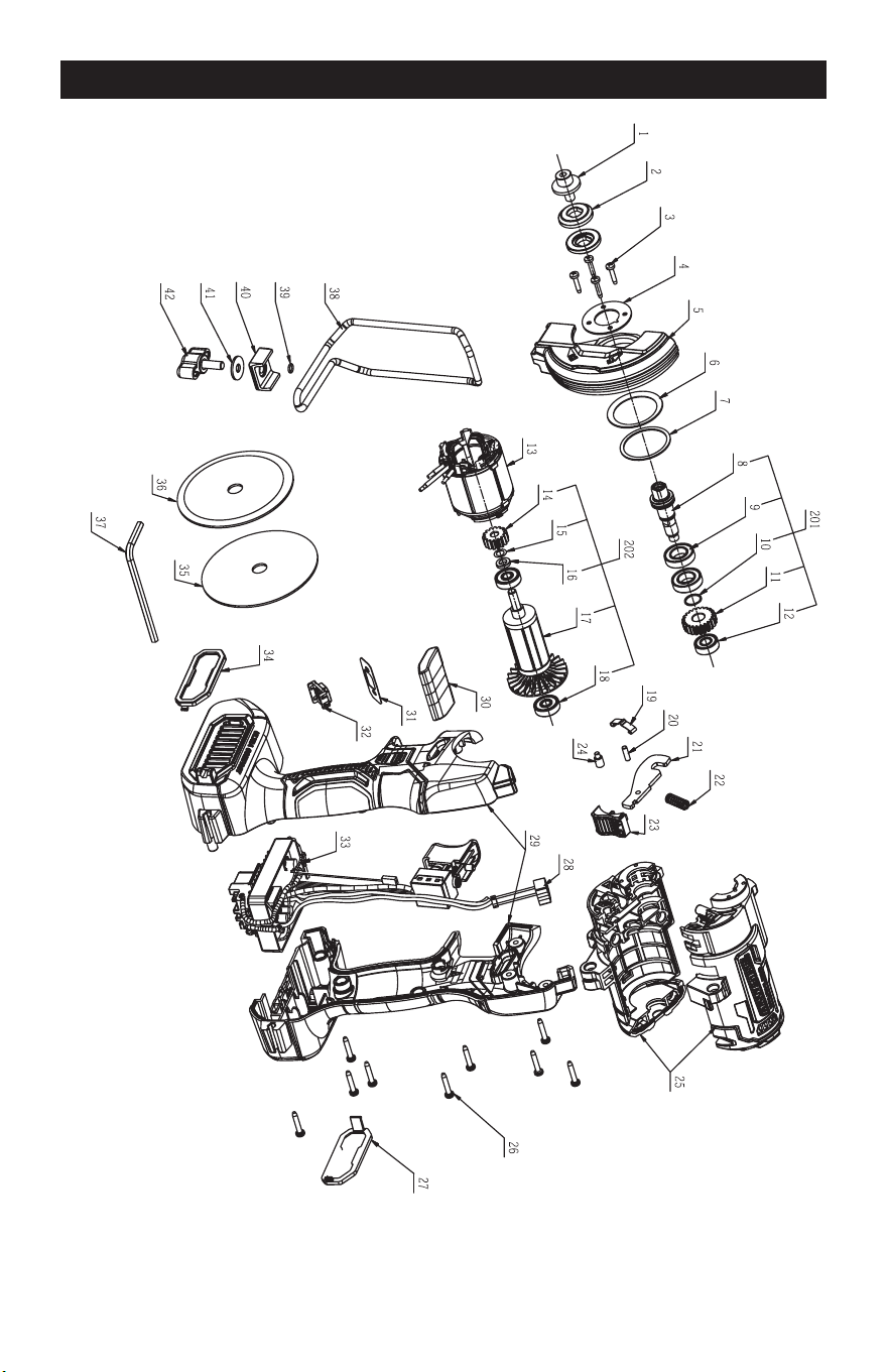
PARTS LIST
No. Part Name No. Part Name
1 Flange Screw 23 Push Button
2 Flange 24 Step Pin
3 Tapping Screw 25 Housing Assembly
4 Pressure Plate 26 Screw
5 Guard 27 Dust Cover
6 Disc Spring 28 LED Electric Assembly
7 Small Washer 29 L R Handle Assembly
8 Output Shaft 30 Switch Button
9 Ball Bearing 31 Indicator Label
10 Spiral Ring For Shaft 32 Button
11 Gear 33 Electric Assembly
12 Ball Bearing 34 Dust Cover
13 Stator 35 Metal Cut-off Wheel
14 Pinion 36 Diamond Tile Cut-off Wheel
15 Washer 37 Hexagon Wrench
16 Holding Ring 38 Wire Guard
17 Rotor Assembly 39 O Ring
18 Ball Bearing 40 Clamp Block
19 Spring Clamp 41 Plain Washer
20 Pin 42 Wing Bolt
21 Limit Plate 201 Output Shaft Assembly
22 Spring 202 Rotor
Page 23
SCHEMATIC DRAWING

Page 24
NOTES

Page 25
NOTES
3” CUT-OFF SAW

07/2024
© 2024 Menard, Inc., Eau Claire, WI 54703