
MILWAUKEE TOOL
l
www.milwaukeetool.com
13135 W. Lisbon Road, Brookeld, WI 53005
Drwg. 2
SCREW TORQUE SPECIFICATIONS PAGE 5
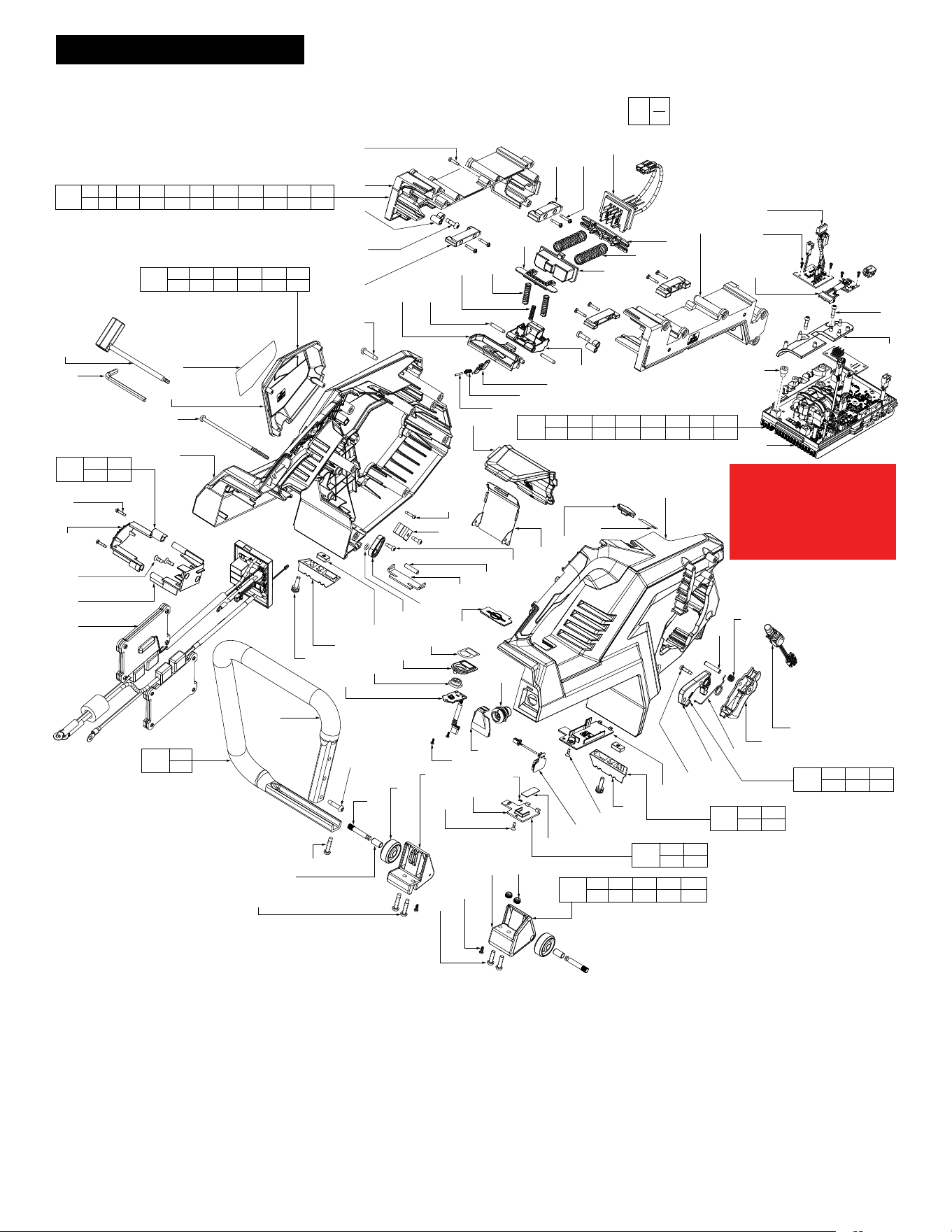
EXPLODED VIEW - One of two PAGE 2
SERVICE BOM LISTING PAGE 4
WIRING INSTRUCTIONS PAGE 6-16
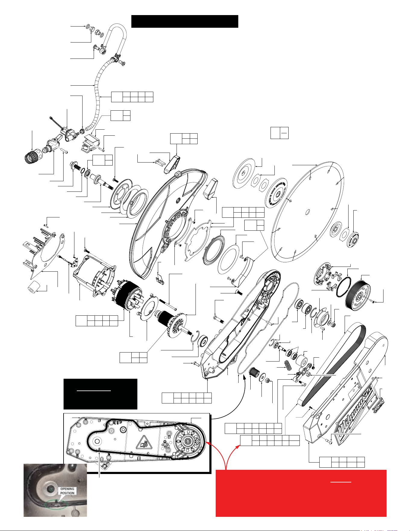
EXPLODED VIEW - Two of two PAGE 3
BULLETIN NO.
54-40-9030
SERVICE PARTS LIST
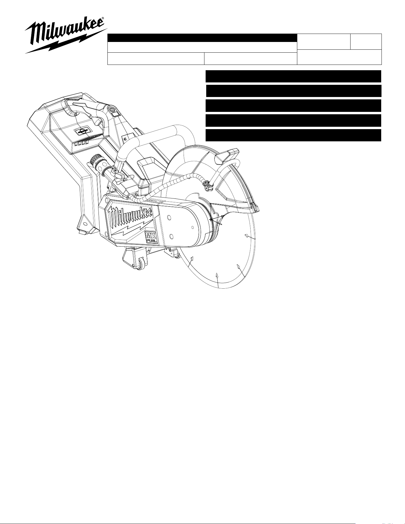
CATALOG NO. MXF315
REVISED BULLETIN
SPECIFY CATALOG NO. AND SERIAL NO. WHEN ORDERING PARTS
MX FUEL 14" CUT-OFF SAW
SERIAL NO.
DATE
July 2024
WIRING INSTRUCTION
N39A
See Pages 6-16
Only maintenance, service, repairs, and replacements of parts as dened in the Operator's Manual
can be performed by the user.
All other repairs are to ONLY be performed by personnel authorized by MILWAUKEE TOOL. Do not
attempt to install other parts; this COULD void your tool warranty.
For service, parts, or inquiries, contact us:
• Customer Service at 1.800.SAWDUST (1.800.729.3878)
• E-Service tool repair at: www.milwaukeetool.com/e-service
• Find a local authorized MILWAUKEE service location at Milwaukeetool.com
• Find a MILWAUKEE factory Service Center Location or MILWAUKEE factory Central Repair
Center at Milwaukeetool.com. Send the following, posted paid and insured:
• Your name, address, and phone number
• Description of the issues
• Copy of the proof of purchase
• Tool, charger, and batteries involved with the issues
MILWAUKEE factory Central Repair Centers:
MILWAUKEE TOOL MILWAUKEE TOOL
Central Repair Central Repair
1401 Sycamore Avenue 2198 Southtech Drive
Greenwood, MS 38930 Greenwood, IN 46143
0
00
EXAMPLE:
Component Parts (Small #) Are Included
When Ordering The Assembly (Large #).
66
(2x)
143
144
(2x)
145
134
156
155
71
(5x)
72
66
(3x)
78
95
(2x)
101
(2x)
94
(2x)
70
(9x)
79
(2x)
80
(8x)
82
103
(2x)
104
100
81
105
(2x)
106
107
(2x)
99
83
74
96
97
98
102
117
(2x)
133
114
(2x)
132
130
128
43
129
(2x)
73
75
157
127
158
126
125
124
76
66
(4x)
131
149
64
(4x)
150
147
(5x)
146
89
(2x)
148
64
(2x)
140
139
(2x)
123
137
(2x)
116
121
122
70
138
(2x)
70
(2x)
53
(2x)
49
(2x)
142
38
(2x)
120
118
116
115
113
89
112
110
108
77
111
109
141
136
135
154
70
201
66 78 79 80 81 82 83 94 95 96 97
98 99 100 101 102 103 104 105 106 107
209
66 70 71 72 74 76
114 123 127 155 156 157
217
66 143
144 145
210
70
141
203
115 117
133
216
38 49 53 70 137
138 139 140 142
218
89 108 109
110 111 112
219
64 77 89 113 116 118 124 125
126 134 146 147 148 149 150 158
220
116 120
121 122
EXPLODED VIEW - One of two
See page four for a complete BOM
(Bill of Material) listing
Do not reuse screws (147).
Always use new screws
(Containing a fresh thread
locking patch).
Torque screws to
39±2 lb-in / 45±3 kgf-cm
*
0
00
EXAMPLE:
Component Parts (Small #) Are Included
When Ordering The Assembly (Large #).
88
(3x)
90
151
(2x)
159
(2x)
152
153
(2x)
160
1
2
3
4
6
7
8
11
5
(6x)
9
(2x)
10
14
(2x)
12
15
67
13
16
7
17
(2x)
58
(3x)
57
18
69
68
44
45
41
40
38
42
46
39
19
20
52
51
33
47
49
(5x)
21
22
23
25
(5x)
43
33
32
24
31
34
35
36
37
(4x)
27
(4x)
30
(4x)
29
28
26
56
(4x)
54
55
59
60
62
65
63
61
5
(4x)
64
(3x)
66
(3x)
50
(2x)
85
(2x)
84
(2x)
86
92
91
161
88
(2x)
87
48
200
20 34 35 36
37 49 170
212
50 70 84 85
86 90 91 92
211
4 19 21 22 23
43 54 55 68
213
5 6 7 8
13 14 15 16
202
20 24 25 26 27 28
29 30 31 32 33 170
215
87
88
214
17
18
205
5 58 59 60
61 62 63 64
206
33 51
52 57
204
2
3
208
9 10
12
207
38 39 40 41 42 46
44 45 47 48 68
19 20
Rubber Seal (20) should start and end at this
position.
For ease of installation of Rubber Seal (20) into
Arm (19), place silicone grease (170),
No. 44-22-0075, into Arm channel prior to
installing the Rubber Seal.
IMPORTANT!
When installing Belt Train Service Kit (202), DO NOT attempt to
reuse existing Rubber Seal (20). Remove and discard old seal
from Arm (19). Replace with new Rubber Seal that is included in
service kit. Be sure new seal is fully seated in channel of Arm. It
is essential that Silicone Grease (supplied in kit) be placed in
channel of Arm for ease of seal installation. Coat top of seal
with grease to assure a tight seal is formed when reassembled.
EXPLODED VIEW - Two of two
See page four for a complete BOM
(Bill of Material) listing
IMPORTANT!
It is MANDATORY to utilize
Silicone Grease (170) when
installing Service Kits
(200 and 202).
*
*
*

FIG. PART NO. DESCRIPTION OF PART NO. REQ.
1 06-14-0013 M10 Hex Hd. Mach. Screw w/ Washer (1)
2 --------------- O-Ring (1)
3 --------------- Arbor Adapter (1)
4 38-50-5385 Output Shaft (1)
5 06-82-9805 M5 x 15mm Pan Hd. PT T-25 Screw (10)
6 --------------- Output Cover (1)
7 --------------- Pivot Shim (2)
8 --------------- Rubber Gasket-1 (1)
9 06-82-2250 M5 x 25 Pan Hd. PT T-25 Screw (2)
10 --------------- Guard Handle Cover (1)
11 43-54-4015 Blade Guard (1)
12 --------------- Guard Handle Support (1)
13 44-66-7320 Plate Guard (1)
14 05-81-0592 M4 x 6.5mm Flat Hd. T-15 Machine Screw (2)
15 --------------- Guard Stop Plate (1)
16 --------------- Rubber Gasket-2 (1)
17 --------------- M4 x 10mm Flat Hd. T-20 Machine Screw (2)
18 --------------- Wear Proof Plate (1)
19 --------------- Arm (1)
20 45-06-5470 Rubber Seal (1)
21 --------------- Ball Bearing (1)
22 --------------- Double Row Bearing (1)
23 --------------- Internal Bevel Retaining Ring (1)
24 --------------- Inner Hub (1)
25 --------------- M5 x 10mm Pan Hd. T-25 Machine Screw (5)
26 --------------- Mechanical Brake Cage (1)
27 --------------- Mechanical Brake Fly Weight (4)
28 --------------- Garter Spring (1)
29 --------------- Driver Pulley with Mods (1)
30 05-81-0594 M4 x 14mm Flat Hd. T-20 ST Screw (4)
31 --------------- Belt 729-3MR-18 (1)
32 45-88-0103 Washer (1)
33 05-55-0025 M8 LH Hex Nut (2)
34 --------------- Arm Cover (1)
35 --------------- Arm Cover Logo Plate (1)
36 --------------- MX Badge (1)
37 06-82-9815 M6 x 18.5mm Pan Hd. T-25 Capt. Mach. Scr. (4)
38 --------------- Nylon Insert Nut (3)
39 --------------- Tensioner Arm (1)
40 --------------- Tensioner Wheel (1)
41 --------------- Deep Groove Ball Bearing (2)
42 --------------- Tensioner Wheel Shaft (1)
43 06-65-7345 5mm x 22mm Nickel Plated Pin (2)
44 --------------- Retaining Ring (1)
45 --------------- Tensioner Wheel Cover (1)
46 --------------- Tensioner Spring (1)
47 --------------- M5 x 21-75mm Cap Hd. Hex Drive Screw (1)
48 --------------- M8 x 1.25mm Hex Nut (1)
49 --------------- M3 x 8mm Pan Hd. T-10 PT Screw (7)
50 45-88-9090 Flat Washer (2)
51 --------------- Driver Rim (1)
52 --------------- Driver Pulley (1)
53 --------------- M5 x 17mm Pan Hd. T-25 Machine Screw (2)
54 --------------- Deep Groove Ball Bearing (1)
55 --------------- Beveled Retaining Ring (1)
56 05-74-0246 M6 x 16mm Pan Hd. T-30 Machine Screw (4)
57 --------------- Rotor (1)
58 05-88-5927 CH K50 Pan Hd. T-20 PT Screw (3)
59 --------------- Bae Insert (1)
60 --------------- Stator (1)
61 --------------- Motor Housing (1)
62 --------------- Ferrite Bead (1)
63 --------------- Hall Board (1)
64 05-88-0083 M2.2 x 6mm Pan Hd. T-8 ST Screw (9)
65 31-05-7065 Motor Housing Bae (1)
66 06-82-1080 M3 x 14mm Pan Hd. T-10 ST Screw (12)
67 40-50-8910 Blade Guard Trim Spring Plate (1)
68 --------------- Tensioner Arm Lock Pin (1)
69 06-14-0380 Special Head Located Bolt (1)
70 06-82-0152 M5 x 22mm Pan Hd. T-25 ST Screw (13)
71 05-88-0087 M5 x 115mm Pan Hd. T-25 PT Screw (5)
72 --------------- Housing Cover (1)
73 43-54-0935 Spark Guard (1)
74 --------------- Buttom Piece (1)
75 14-20-0935 Load LED and OneKey LED (1)
76 --------------- Housing Support (1)
77 45-72-0145 Switch Assembly (1)
78 --------------- Battery Rail Cover (1)
79 --------------- Front Metal Rail (2)
80 --------------- M3 x 16mm Pan Hd. ST Tamperproof Scr. (8)
81 --------------- Ejection Spring Holder (1)
82 --------------- Battery Terminal Block (1)
83 --------------- Battery Rail Support (1)
84 05-74-7140 Banjo Bolt (2)
85 31-01-2145 Nozzle (2)
86 --------------- Water Valve Assembly-II (1)
87 --------------- Water Valve Shell (1)
88 06-82-0044 M4 x 18mm Pan Hd. T-20 ST Screw (5)
89 06-82-4003 M4 x 16mm Pan Hd. T-20 ST Screw (3)
90 --------------- Valve Body Assembly (1)
91 --------------- Electrical Water Valve (1)
SERVICE BILL OF MATERIAL (BOM) LISTING
FIG. PART NO. DESCRIPTION OF PART NO. REQ.
92 --------------- Clamp (1)
94 --------------- Rear Metal Rail (2)
95 --------------- Pivot Bushing (2)
96 --------------- Lock O Lever Pin (1)
97 --------------- Lock O Lever Torsion Spring (1)
98 --------------- Lever Lock Out (1)
99 --------------- Release Lever (1)
100 --------------- Pivot Latch Spring Holder (1)
101 --------------- M5 x 16mm Pan Hd. T-25 ST Screw (2)
102 --------------- Latch (1)
103 --------------- Spring (2)
104 --------------- Battery Ejector (1)
105 --------------- Spring (2)
106 --------------- Spring (1)
107 --------------- Pivot Shaft (2)
108 --------------- Trigger (1)
109 --------------- Trigger Spring (1)
110 --------------- Torsion Spring (1)
111 --------------- Trigger Pin (1)
112 --------------- Shark Fin (1)
113 22-80-0305 Program Board Cover (1)
114 06-54-0355 Control Nut (2)
115 --------------- Rear Rubber Boot - Left (1)
116 06-82-9280 Drop O Screw (2)
117 --------------- M5 x 20mm Pan Hd. T-25 Screw w/Washer (2)
118 --------------- Coin Cell Board (1)
119 --------------- 3V Coin Cell (CR2032) (Not Shown) (1)
120 --------------- Anti-Static Seal (1)
121 --------------- Coin Cell Cover (1)
122 --------------- C Ring - E Type (1)
123 45-72-0165 Panel Connector Cover (1)
124 22-80-0310 Arm Board (1)
125 --------------- Rubber Arm Button (1)
126 --------------- Arm Button Housing (1)
127 44-66-7340 Rapid Stop Plate (1)
128 43-74-0735 Rear Insert (1)
129 06-82-0032 M4 x 12mm Pan Hd. T-20 ST Screw (2)
130 45-96-2545 Hex Key Retaining Cover (1)
131 44-86-3215 Wrench Retainer (1)
132 34-40-4480 O-Ring (1)
133 --------------- Rear Rubber Boot - Right (1)
134 22-80-0315 Brake Board (1)
135 49-96-0021 Hex Key (1)
136 49-96-0031 Scwrench (1)
137 --------------- Wheel Shaft (2)
138 --------------- Bushing (2)
139 --------------- Wheel (2)
140 --------------- Wheel Foot - Left (1)
141 --------------- Bale Handle (1)
142 --------------- Wheel Foot - Right (1)
143 --------------- Resistor Mounting Bracket (1)
144 05-78-0135 M4 x 12mm Flat Hd. ST Philips Screw (2)
145 --------------- Resistor Holder (1)
146 22-80-0307 Control Board (1)
147 06-82-9820 M6 x 7mm Cap Hd. Hex Drive Mach. Screw (5)
148 22-38-0365 Wire Trap Cover (1)
149 22-80-0325 BLE Board (1)
150 22-80-0330 IMU Board (1)
151 43-34-2735 Large Saw Flange (2)
152 49-93-7540 Diamond Ultra Blade (Accessory) (1)
153 43-34-2745 Blade Flange (2)
154 23-56-0055 Panel Connector (1)
155 --------------- B-Side Logo Cover (1)
156 12-20-9930 Service Nameplate (1)
157 10-22-0589 One Key Bluetooth Label (1)
158 10-20-3237 MX Fuel Label (1)
159 10-20-3654 Reversible Arbor Adapter Label (2)
160 10-22-0590 Reversible Arbor Adapter Label (1)
161 43-33-0130 Quick Hose Connector Assembly (1)
170 44-22-0075 Silicone Grease, 5ml tube (Not Shown) (1)
200 14-46-9602 Arm Cover Service Kit (1)
201 14-46-9604 Battery Rail Service Assembly (1)
202 14-46-9606 Belt Train Service Kit (1)
203 14-46-9657 Rear Foot Kit (1)
204 14-46-9608 Arbor Adaptor Service Kit (1)
205 14-46-9612 Motor Stator Service Kit (1)
206 14-46-9614 Rotor Service Kit (1)
207 14-46-9616 Tensioner Service Kit (1)
208 14-46-9618 Guard Handle Service Kit (1)
209 14-46-9622 Housing Service Kit (1)
210 14-46-9624 Bale Handle Service Kit (1)
211 14-46-9627 Arm Assembly Service Kit (1)
212 14-46-9629 Water Delivery System Service Kit (1)
213 14-46-9632 Guard Service Kit (1)
214 14-46-9634 Wearing Proof Plate Service Kit (1)
215 14-46-9636 Valve Shell Service Kit (1)
216 14-46-9638 Wheel Foot Service Kit (1)
217 14-46-9643 Brake Resistance Holding Service Kit (1)
218 14-46-9647 Trigger Service Kit (1)
219 14-20-9503 PCBA Service Kit (1)
220 22-09-6615 Coin Cell Cover Service Kit (1)
SCREW TORQUE SPECIFICATIONS
SEAT TORQUE
FIG. PART NO. DESCRIPTION OF FASTENER WHERE USED (LBS.IN) (KGF.CM)
5 06-82-9805 M5 x 15mm Pan Hd. PT T-25 Screw Motor Housing 52±4 60±5
5 06-82-9805 M5 x 15mm Pan Hd. PT T-25 Screw Output Cover 52±4 60±5
9 06-82-2250 M5 x 25 Pan Hd. PT T-25 Screw Guard Handle Cover 21±1 25±2
14 05-81-0592 M4 x 6.5mm Flat Hd. T-15 Machine Screw Plate Guard / Blade Guard 8±1 10±1
17 --------------- M4 x 10mm Flat Hd. T-20 Machine Screw Wear Proof Plate 13±1 15±1
25 --------------- M5 x 10mm Pan Hd. T-25 Machine Screw Inner Hub 26±2 30±3
30 05-81-0594 M4 x 14mm Flat Hd. T-20 ST Screw Driver Pulley with Mods 13±1 15±1
33 05-55-0025 M8 LH Hex Nut Threaded End of Rotor 86±8 100±10
33 05-55-0025 M8 LH Hex Nut Threaded End of Output Shaft 260±8 300±10
37 06-82-9815 M6 x 18.5mm Pan Hd. T-25 Capt. Mach. Scr. Arm Cover 21±1 25±2
38 --------------- Nylon Insert Nut End of Tensioner Wheel Shaft 13±1 15±2
47 --------------- M5 x 21-75mm Cap Hd. Hex Drive Screw Tensioner Arm 26±2 30±2
48 --------------- M8 x 1.25mm Hex Nut End of Tensioner Arm Lock Pin 86±8 100±10
49 --------------- M3 x 8mm Pan Hd. T-10 PT Screw Arm Cover 3.0±1 3.5±1
53 --------------- M5 x 17mm Pan Hd. T-25 Machine Screw Wheel Foot - Right 21±1 25±2
56 05-74-0246 M6 x 16mm Pan Hd. T-30 Machine Screw Arm 30±2 35±3
58 05-88-5927 CH K50 Pan Hd. T-20 PT Screw Bae Insert / Motor Housing 21±1 25±2
64 05-88-0083 M2.2 x 6mm Pan Hd. T-8 ST Screw Hall Board 1.7±0.5 2±0.5
64 05-88-0083 M2.2 x 6mm Pan Hd. T-8 ST Screw Arm Board 1.7±0.5 2±0.5
64 05-88-0083 M2.2 x 6mm Pan Hd. T-8 ST Screw BLE Board / IMU Board 1.7±0.5 2±0.5
66 06-82-1080 M3 x 14mm Pan Hd. T-10 ST Screw Motor Housing Bae 3.4±1 4±1
66 06-82-1080 M3 x 14mm Pan Hd. T-10 ST Screw Battery Rail Cover 4.3±1 5±1
66 06-82-1080 M3 x 14mm Pan Hd. T-10 ST Screw Resistor Mounting Bracket 10±1 12±1
66 06-82-1080 M3 x 14mm Pan Hd. T-10 ST Screw Housing Cover / B-Side Logo Cover 6±1 7±1
69 06-14-0380 Special Head Located Bolt Arm 17±1 20±2
70 06-82-0152 M5 x 22mm Pan Hd. T-25 ST Screw Housing Cover 15.6±1 18±1.5
70 06-82-0152 M5 x 22mm Pan Hd. T-25 ST Screw Bale Handle 21±1 25±2
70 06-82-0152 M5 x 22mm Pan Hd. T-25 ST Screw Wheel Foot - Left 21±1 25±2
70 06-82-0152 M5 x 22mm Pan Hd. T-25 ST Screw Valve Body Assembly 21±1 25±2
71 05-88-0087 M5 x 115mm Pan Hd. T-25 PT Screw Housing Cover 15.6±1 18±1.5
80 06-82-9630 M3 x 16mm Pan Hd. ST Tamperproof Scr. Front & Rear Metal Rails 4.3±1 5±1
84 05-74-7140 Banjo Bolt Water Valve Assembly-II 34±2 40±3
88 06-82-0044 M4 x 18mm Pan Hd. T-20 ST Screw Water Valve Shell 11.7±1 13.5±1
89 06-82-4003 M4 x 16mm Pan Hd. T-20 ST Screw Wire Trap Cover 13±1 15±1
89 06-82-4003 M4 x 16mm Pan Hd. T-20 ST Screw Shark Fin 7.8±1 9±1
101 06-82-0029 M5 x 16mm Pan Hd. T-25 ST Screw Pivot Bushing 13±1 15±1
116 06-82-9280 Drop O Screw Program Board Cover 3±1 3.5±1
117 --------------- M5 x 20mm Pan Hd. T-25 Screw w/Washer Rear Rubber Boot - Right & Left 13±1 15±1
129 06-82-0032 M4 x 12mm Pan Hd. T-20 ST Screw Hex Key Retaining Cover 9.5±1 11±1
144 05-78-0135 M4 x 12mm Flat Hd. ST Philips Screw Resistor Holder 6.9±1 8±1
147 06-82-9820 M6 x 7mm Cap Hd. Hex Drive Mach. Screw Control Board 39±2 45±3
154 23-56-0055 Panel Connector Housing Support 8±1 10±1
1
2
3
4
5
6
7
8
9
10
1
2
3
4
6
7
8
5
9
10
11
11
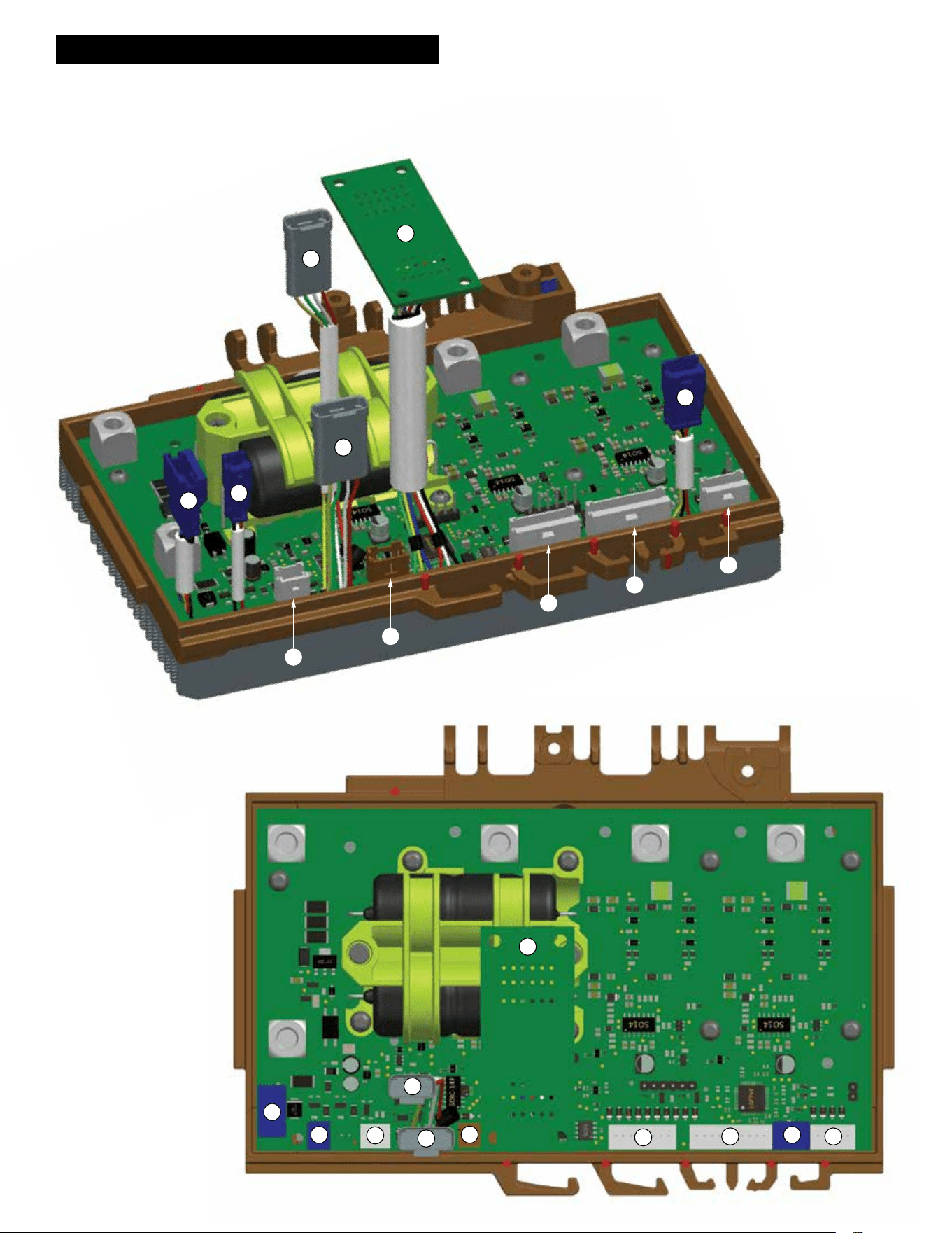
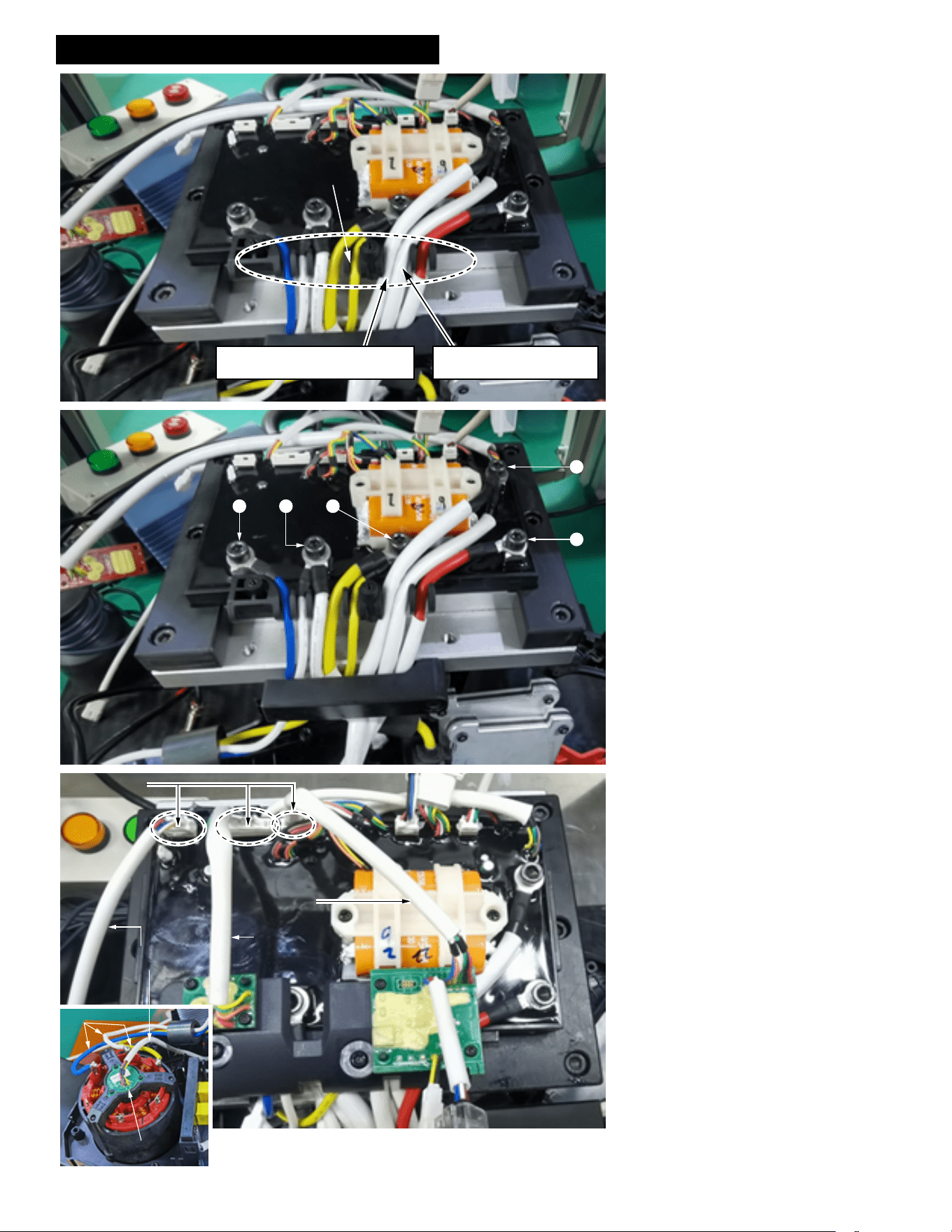
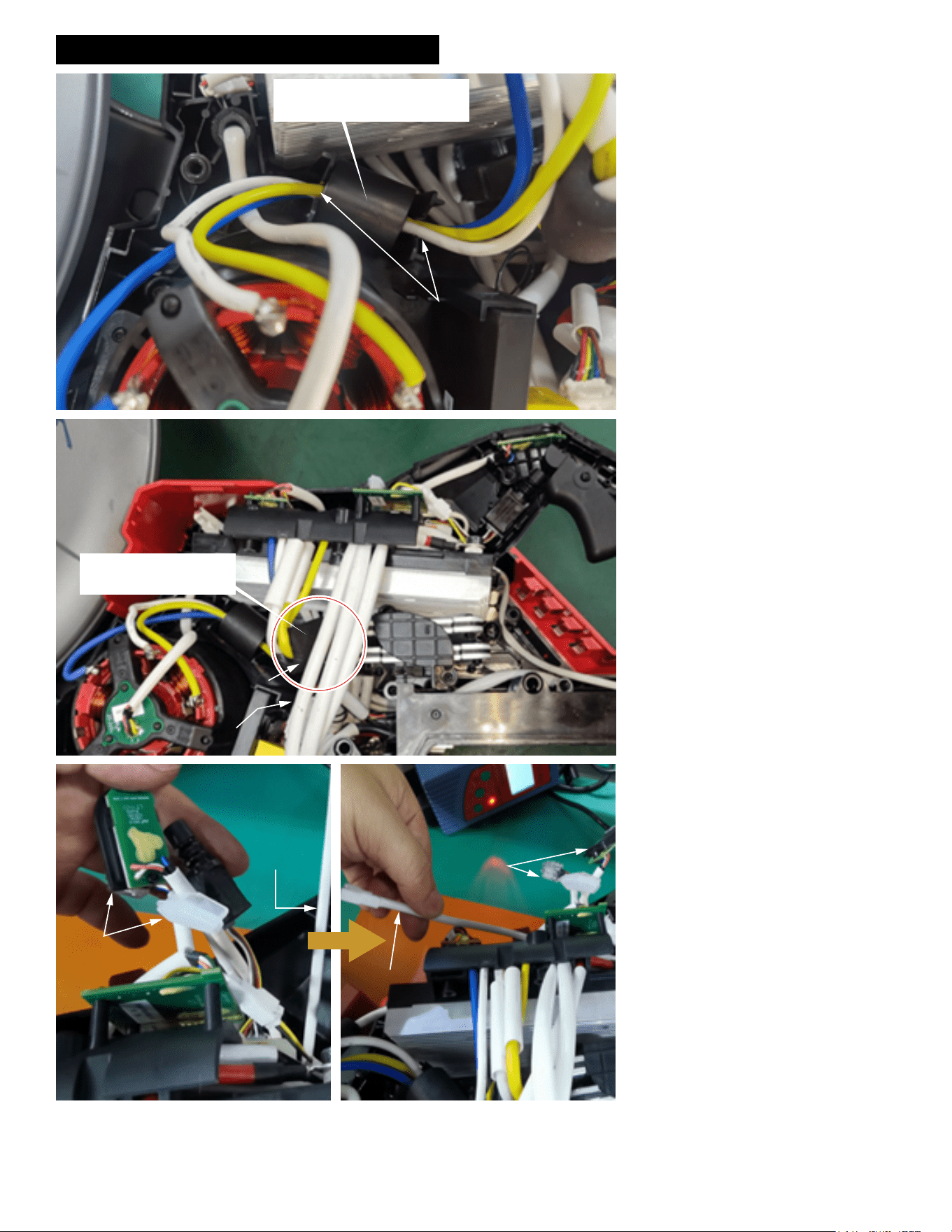
WIRING INSTRUCTIONS - Control Board Detail
1. Terminal connect with battery communications.
2. Terminal connect with watervalve.
3. Terminal connect with saw trigger.
4. Terminal connect with cart
connector trigger signals.
5. Terminal connect with
motor braking enable.
6. Load light connects here.
7. Arm button/LED connects here.
8. Bluetooth board connects here.
9. IMU/antikickback board connects here.
10. Motor hall signals connect here.
11. Interface board.
NOTE: All connectors get electrical grease.
WIRING INSTRUCTIONS - Sheet 1 of 10
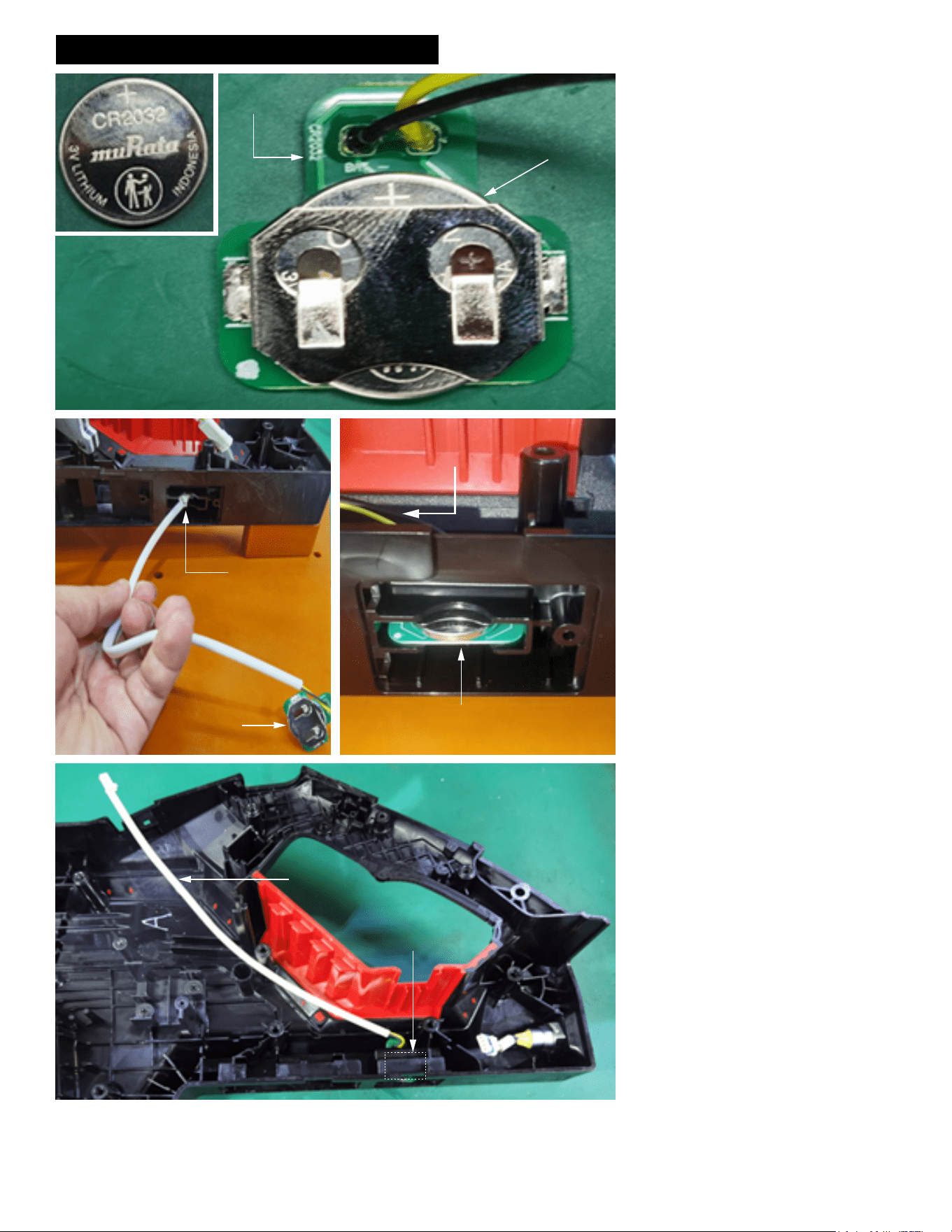
Panel
Connector
3V Coin Cell Battery
Coin Cell Battery
(Install with the
positive character
face up)
Coin Cell
Board
Insert Coin Cell
connector and
wires through
middle opening in
Housing Support
Coin Cell
Board
Coin Cell Board inserted in middle slot
with coin cell facing up and PCB facing
down
Coin Cell connector and
wires pulled this way
Coin Cell Board
Coin Cell
wires and
connector
NOTE: 3V coin cell batteries (CR2032) are
avaiable at most hardware or retail stores.
Install the coin cell battery onto the coin cell
PCB assembly as shown.
Be sure that the coin cell is oriented with the '+'
symbol facing upward.
Install the coin cell PCB assembly into the
housing support.
Feed the coin cell connector and wires through
the middle opening located on the bottom of
the housing support.
Pull the connector and wires taunt, while
seating the coin cell PCBA in that middle slot.
Be sure that the PCBA is rmly and squarely
seated in the cavity.
Be sure the PCBA is oriented with the coin cell
facing up and the PCB facing down as shown.
WIRING INSTRUCTIONS - Sheet 2 of 10
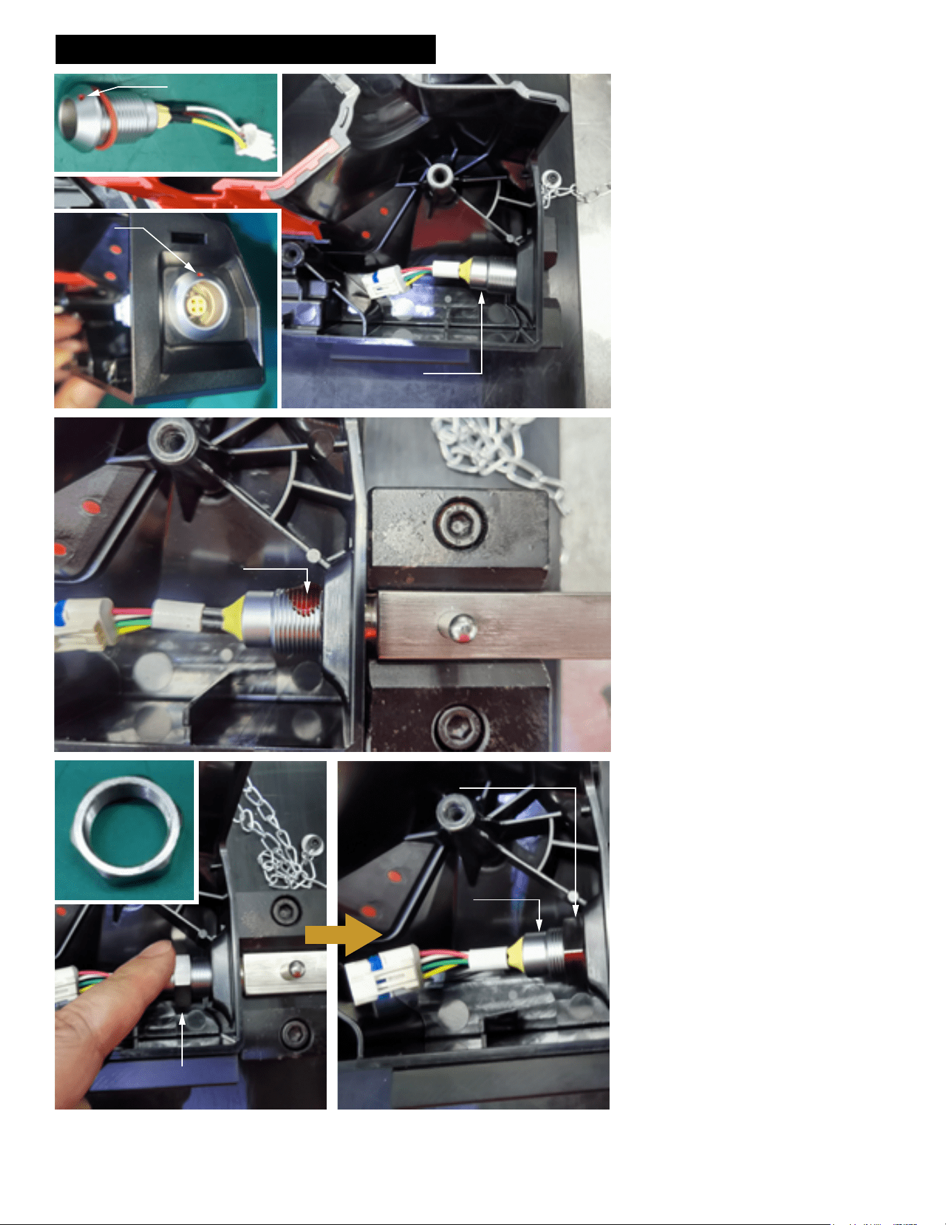
Red Dot
Panel Connector
Red Dot
of Panel
Connector
positioned
upward
Panel Connector
Apply Red Loctite 277
to at least three threads
of Panel Connector
Panel
Connector
Hex Nut
Panel Connector Hex Nut
Hand tighten Panel Connector
Hex Nut to the end
Panel
Connector
When installing the panel connector into the
housing support be sure that the red dot is fac-
ing upward at the 12:00 position.
Apply a drop of Red Loctite 277 to at least 3
threads of the panel connector.
Feed hex nut over panel connector wires and
onto the threaded portion of the panel connec-
tor. Screw the hex nut clockwise by hand until
nut is snug at the end.
WIRING INSTRUCTIONS - Sheet 3 of 10
Tab
Panel
Connector
Cover
Slot
Panel Connector Cover
Tab
Control
Board
1
2
3
Torque Wrench
Service tool attached to
torque wrench to tighten
Panel Connector
Hex Nut
NOTE:
This illustration shows a torque wrench and service tool being utilized for production.
For service, a conventional wrench may be used to secure the panel connector in
place.
NOTE:
This illustration shows a torque wrench and
service tool being utilized for production.
For service, a conventional wrench may be
used.
Place a drop of Red Loctite 277 on threads of
panel connector. Use a wrench to secure the
panel connector hex nut in place. Hand tighten
clockwise until snug.
Install the panel connector cover onto the sup-
port housing by locating the tab on the top of
the panel connector cover.
Insert the tab through the slot in the support
housing. on the other side of the support hous-
ing, pull the tab by hand to asure the complete
tab is through the slot.
Press the panel connector cover to the support
housing to seal the opening that protects the
panel connector.
Insert the brake board with resistors in the tool
and rest the control board near the tool. This
must be done prior to any placement of the
berglass sleeves.
Pull the three berglass wire sleeves to keep
them as far away from the control board as
possible.
WIRING INSTRUCTIONS - Sheet 4 of 10
Place wires in wire traps as shown
Note: The Brake_GND black wire
is on the left side of the trap
Note: The B- black wire is
on the right side of the trap
4
5
1 2
3
Hall Board
Signal Wires
Bluetooth
Board Wires
IMU
Board Wires
Connectors
Motor Wires
Hall Board
Route wires and place in wire traps as shown.
With wires placed down rmly in wire traps,
secure by tightening screws.
Before connecting the hall board and other
boards to the control board, the ring terminal
cover needs to be screwed down and the
Bluetooth Board and the IMU board need to be
screwed to the ring terminal cover.
Apply electrical grease to hall board signal
connector prior to attaching to control board.
Be sure the hall board wires are routed below
the three motor phase wires.
Apply electrical grease to IMU board connector
prior to attaching to control board.
Apply electrical grease to bluetooth board con-
nector prior to attaching to control board.
Before connecting the hall board and other
boards to the control board, the ring terminal
cover needs to be screwed down and the
Bluetooth Board and the IMU board need to be
screwed to the ring terminal cover.
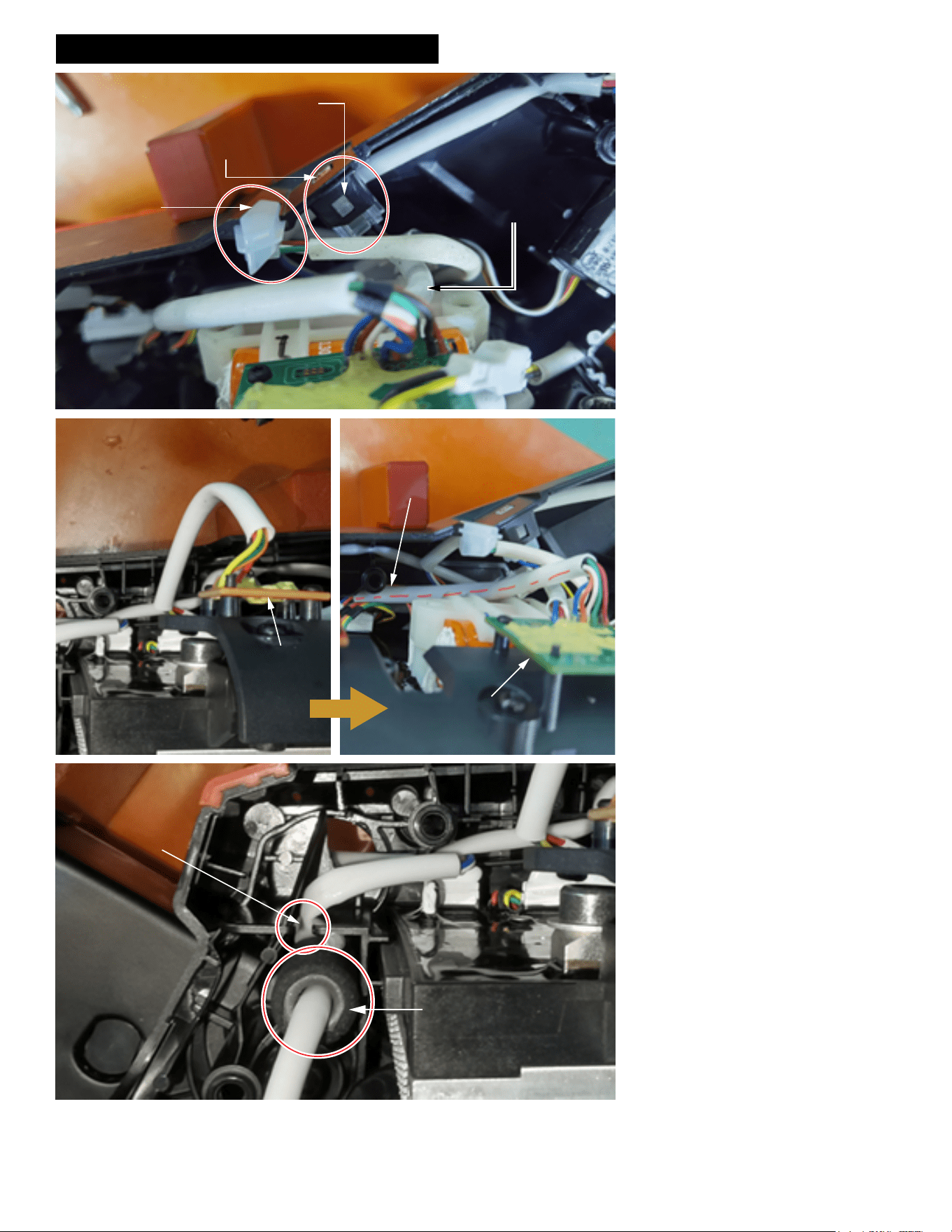
WIRING INSTRUCTIONS - Sheet 5 of 10
41 2
3
Support Housing
Slot (Right)
Control Panel
Rib (Right)
Control Panel
Rib (Left)
Support Housing
Slot (Left)
Control Board
Ribs on both sides of
Control Board
Route wires and place in wire traps as shown.
Note that the sleeved wires are routed down-
ward towards the housing half and the phase
wires go up.
Press the four sleeved wires into slot with your
hand.
Install the control board into the support hous-
ing by lining up the side ribs of the control
board with the corresponding slots in the sup-
port housing. Insert the control board assembly
rmly and squarely until it bottoms out.
WIRING INSTRUCTIONS - Sheet 6 of 10
As shown in the illustrated detail, route the
four wire assemblies from the bottom of the
control board upward and into the wire traps
as shown.
Place cart wire assembly in bottom of right
wire trap.
Place interface board wire assembly in right
wire trap over the cart wire assembly. Press
both wire assemblies down rmly in trap.
Route the brake board signal wire assembly
in the left wire trap. Be sure to press wire as-
sembly down rmly.
Install interface board onto the support hous-
ing as shown in detail. Slide interface board
into cavity of support housing an secure by
placing the slot in the board onto the tab in the
support housing.
Route the interface board wires as shown,
tucking the wire assembly into the wire traps
od the support housing. Push wires completely
down in traps.
Join together the connectors from the BLE
board and the coin cell board. Prior to installa-
tion, apply electrical grease to the connectors.
Route coin cell wires from the top and route
downward. Place wires in traps while taking
the slack from the wire assembly. This is done
to allow the maximum amount of wire at the
end for ease of coin cell replacement.
Battery platform signal wires
(short, thick) above other wires
(no need to put on the slot)
The brake board signal wires
(short, thin) should be placed
in the left slot
The interface board wires should
be placed above in right slot
The cart wires (long and thin) should
be placed under the interface board
wires in the right slot
Route the 4 wires harness from
bottom control board and place
them into corresponding slots
Tab in
Support
Housing
Slot in
Interface
Board
Route the Interface Board wires as shown.
Place the sleeved wires in the two wire traps
being sure to push them completely to the
bottom.
Join BLE Board and Coin
Cell Board connectors
together
BLE Board
Coin Cell Board wires
Place Coin Cell wires
in wire traps
BLE Board
WIRING INSTRUCTIONS - Sheet 7 of 10
Route the Cart Wire Assembly
through Wire Traps (4 places)
Join the connector
of the Cart Wire to the
Panel Connector
Brake Signal Wires
Battery Platform
Signal Wires
Note: Battery Platform
Wire harness is routed
above the red and
blue marked lines
Place Brake Signal Wires (blue) in wire
trap first. Place Brake U Wires (Red) on
top in the wire trap.
As shown, join the Brake Signal Wires’
connector.
Join the Battery Platform signal wires
connectors together as shown
Battery Platform
Battery Platform
signal wires
Route the sleeved cart wires as shown, being
sure that the wires are placed in the four wire
traps. Be sure the sleeved wires are pushed
down as far as possible in each trap.
Join the connector of the cart wire assembly
with the connector of the panel connector.
Prior to installation, apply electrical grease to
the connectors.
Place the sleeved brake signal wires (blue) in
the bottom of the wire trap as shown.
Place the sleeved brake U wires (red) in the
wire trap on top.
Attach the brake signal wire connector as
shown. Prior to joining, apply electrical grease
to the connectors.
Be sure the battery platform signal wire har-
ness is routed above the red and blue marked
lines.
Attach the battery platform signal wire connec-
tor as shown. Prior to joining, apply electrical
grease to the connectors.
WIRING INSTRUCTIONS - Sheet 8 of 10
Put the ferrite bead in place. Push
the three phase wires down into
wire traps as shown.
Wire Traps
Place the snake resistor’s
ferrite bead under 3 wires,
as shown.
Ferrite
Bead
3 wires
{
Raise all short wire
parts up (Arm Board/
Trigger/Load Light/
BLE LED) as shown
Pull the Water Valve wires
from under short wire parts
Short wire
parts
Water Valve
Wire Harness
Water Valve
Wire Harness
Short wire
parts
Install ferrite bead into support housing cavity
as shown. Secure the ferrite bead by pushing
the corresponding blue, yellow and white mo-
tor phase wires down in the traps located on
both sides of the cavity.
Tuck the snake resistor ferrite bead under the
three sleeved wires as shown.
Raise all short wire parts upward (arm board
assembly, trigger assembly, load light assem-
bly and BLE LED).
As shown, pull the water valve wires from
under the short wire parts.
WIRING INSTRUCTIONS - Sheet 9 of 10
Route the connector of
the Water Valve through
the hole in the Support
Housing as shown.
Hole in
Support
Housing
Gently pull out Water Valve
wires from the outside of
Support Housing by hand
as shown
Hole in
Support
Housing
Continue to route the Water
Valve wires and press wires
into these 2 wire traps.
Three traps total.
Route the Water Valve wires
behind the other wires as
shown. Press the wire
down into trap.
Note: Both ends of the
Arm Board Ass’y need to
be inserted into the
corresponding two slots
of Support Housing.
Trap sleeved wires here.
Switch is to be
positioned with the
manufacturers markings
facing up. Place Switch
in corresponding cavity.
BLE LED Wires
Load LED Wires
Note: The Switch/Trigger
Wires and Arm Board Wires
are under Load LED Wires
and Bluetooth LED Wires.
Route water valve wires and connector
through the hole in the support housing.
From the outside of the support housing, gen-
tly pull the water valve connector and wires.
Route the water valve wires behind the other
wires shown in the illustration. Place the wires
in wire traps (3 total).
Carefully place arm board assembly into slot
of support housing. Be sure both ends of the
board are captured in the slots.
Place arm board wires into wire trap and route
under the load LED wires and bluetooth LED
wires.
Note: The Switch wires are also positioned
behind the load LED wires and bluetooth LED
wires.
Position the switch body in the switch cavity
with markings on switch facing upward.
WIRING INSTRUCTIONS - Sheet 10 of 10
Install the BLE LED, to make
the buckle close on
Note: The BLE wire harness
is under the Load LED
Press BLE LED with your
finger to ensure that the LED
is not loose in the slot
Install Load LED
in this slot
As shown, press the
IMU Board Wires to
the Control Board
side, under the post
IMU Board
IMU Board
Press the Hall
Board wires into
this wire trap
Press the small ferrite bead
vertically into the cavity as
shown
Route the BLE wire harness under the load
LED and install the BLE LED as shown.
Install the load LED as shown.
Route the IMU board wires under the post in
the support housing as illustrated.
Secure the sleeved hall board wires in wire
trap of support housing.
Insert the small ferrite bead vertically into the
cavity of the support housing.