
Only maintenance, service, repairs, and replacements of parts as dened in the Operator's Manual
can be performed by the user.
All other repairs are to ONLY be performed by personnel authorized by MILWAUKEE TOOL. Do not
attempt to install other parts; this COULD void your tool warranty.
For service, parts, or inquiries, contact us:
• Customer Service at 1.800.SAWDUST (1.800.729.3878)
• E-Service tool repair at: www.milwaukeetool.com/e-service
• Find a local authorized MILWAUKEE service location at Milwaukeetool.com
• Find a MILWAUKEE factory Service Center Location or MILWAUKEE factory Central Repair
Center at Milwaukeetool.com. Send the following, posted paid and insured:
• Your name, address, and phone number
• Description of the issues
• Copy of the proof of purchase
• Tool, charger, and batteries involved with the issues
MILWAUKEE factory Central Repair Centers:
MILWAUKEE TOOL MILWAUKEE TOOL
Central Repair Central Repair
1401 Sycamore Avenue 2198 Southtech Drive
Greenwood, MS 38930 Greenwood, IN 46143
MILWAUKEE TOOL
l
www.milwaukeetool.com
13135 W. LISBON RD., BROOKFIELD, WI 53005
Drwg. 5
BULLETIN NO.
54-40-9020
SERVICE PARTS LIST
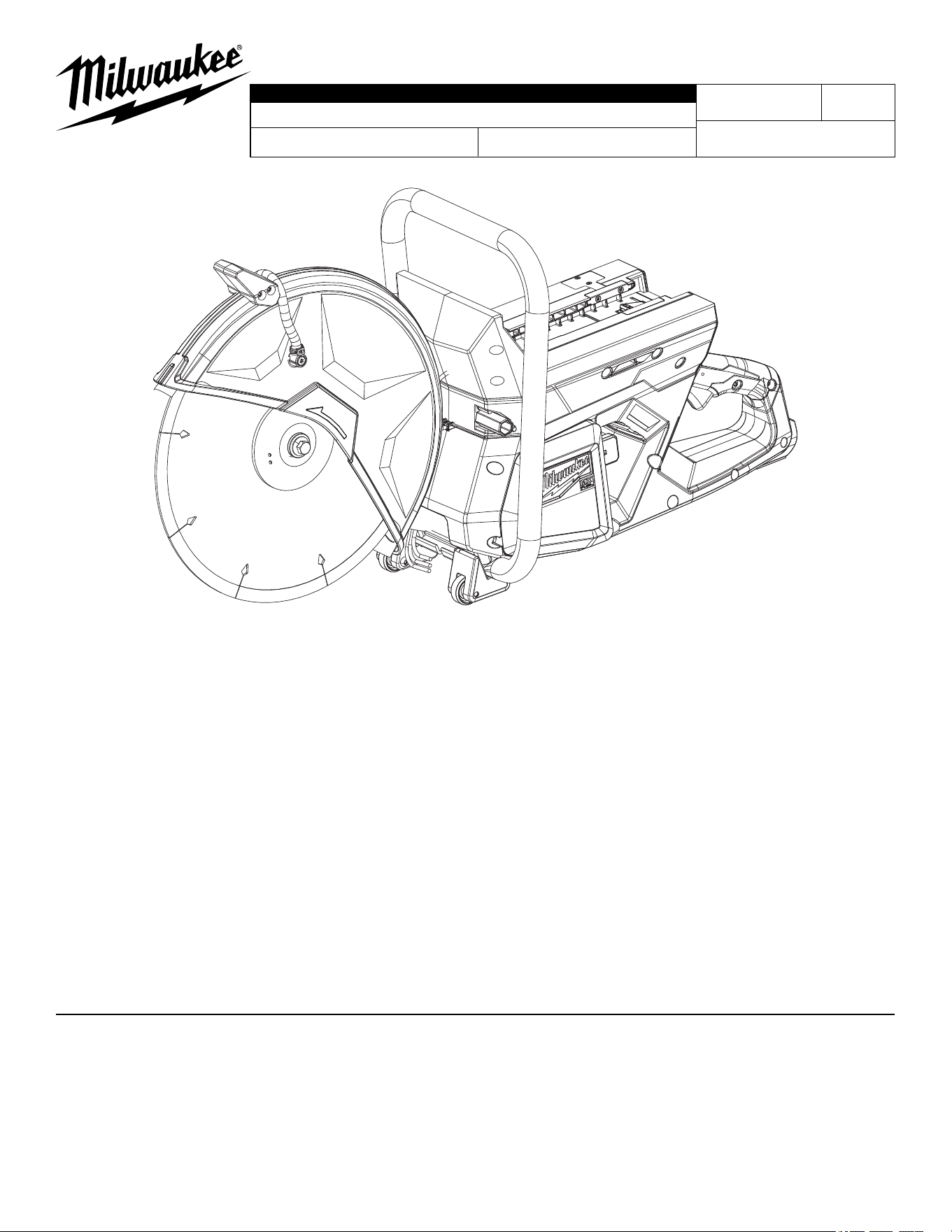
CATALOG NO. MXF314
REVISED BULLETIN
SPECIFY CATALOG NO. AND SERIAL NO. WHEN ORDERING PARTS
MX FUEL™ 14" Cut-O Machine (Saw)
DATE
July 2024
WIRING INSTRUCTION
K26A
See Pages 3 thru 6
SERIAL NO.
EXAMPLE:
Component Parts (Small #) Are Included
When Ordering The Assembly (Large #).
0
00
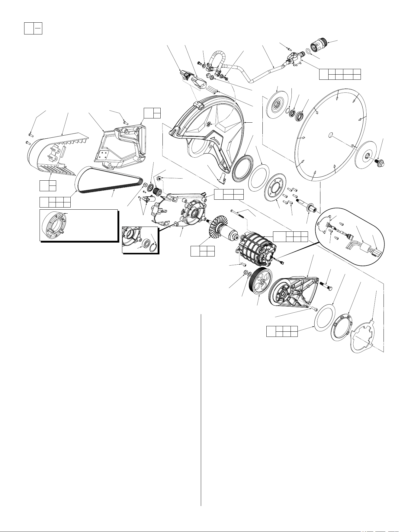
FIG. PART NO. DESCRIPTION OF PART NO. REQ.
1 06-14-0013 Blade Bolt LH (1)
2 43-34-0023 Blade Flange (2)
3 42-04-0015 Arbor Adapter (1)
4 34-40-0113 O-Ring (1)
5 45-08-0039 Output Shaft (1)
6 05-74-0990 M5 x 15mm Pan Hd. Taptite T-25 Scr. (6)
7 --------------- Output Cover (1)
8 --------------- Pivot Shim (2)
9 05-88-0046 M5 x 38mm Pan Hd. T-25 Machine Scr. (2)
10 --------------- Rubber Gasket 1 (1)
11 31-50-0017 Guard Handle Cover-Left (1)
12 28-41-0017 Blade Guard (1)
13 --------------- Guard Stop Plate (1)
14 31-44-0207 Guard Handle Support-Right (1)
15 --------------- Rubber Gasket 2 (1)
16 42-09-0031 Front Arm Assembly (1)
16e 06-14-0021 5/16-18UNC M13 Hex Bolt (3)
17 45-04-1090 M6 x 16mm Hex Skt. Mach. Screw (1)
18 --------------- Driven Pulley (1)
19 45-88-0103 M8 Flat Washer (1)
20 05-55-0025 M8 LH Hex Nut (2)
21 --------------- Synchronous Drive Belt (1)
22 --------------- M6 x 12mm T-25 Stainless Steel Screw (2)
23 --------------- Valve Assembly (1)
24 --------------- Spray Nut (2)
25 --------------- Front Arm Cover (1)
26 06-82-3065 M5 x 15mm Pan Hd. T-25 Mach. Screw (6)
27 --------------- Back Arm Cover Assembly (1)
28 06-82-0032 M4 x 12mm Pan Hd. ST T-20 Screw (3)
29 43-33-0130 Quick Hose Connector Assembly (1)
61 06-82-0196 M2.5 x 6mm Pan Hd. Tapt. T-8 Screw (3)
62 06-82-0197 M6 x 14mm Pan Hd. Tapt. T-30 Screw (4)
63 --------------- Hall Board Assembly (1)
66 05-88-5927 M4 x 64mm Pan Hd. T-20 PT Screw (3)
67 23-40-0012 Rotor Assembly (1)
68 42-09-0013 Back Arm Assembly (1)
68a --------------- Back Arm (1)
68b 02-04-0066 Ball Bearing (1)
68c 34-80-0210 Retaining Ring (1)
69 --------------- Driver Pulley (1)
70 --------------- Driver Rim (1)
71 05-55-0027 5/16-18UNC Flange Nut (3)
72 31-01-0026 Tensioner Arm (1)
89 42-25-0012 Belt Installation Tool (1)
91 --------------- Rubber Spray Nut Cap (2)
92 43-54-0019 Blade Guard Trim (1)
94 14-32-0055 Plate/Gasket/Cover Kit (1)
95 42-70-0012 Belt Pulley Kit (1)
96 42-92-0093 Belt Cover Kit (1)
97 45-80-0012 Hose/Valve Assembly (1)
111 42-09-0033 Back Arm Cover Kit (1)
112 23-58-0010 Stator Assembly (1)
113 34-40-0166 O-Ring (1)
114 42-04-0031 7/8" Arbor Adapter (1)
1
2
(2x)
4
3
114
28
(3x)
23
22
(2x)
24
(2x)
9
(2x)
12
10
8
6
(6x)
7
5
1114
13
15
8
16e
(3x)
17
18
19
20
62
(4x)
68a
72
20
21
71
(3x)
69
70
16
26
(2x)
25 27 26
(4x)
97
22 23 24 28
29 91 113
94
6 7 8
10 13 15
96
25
26
111
26
27
95
18 19 20
21 89
68
68a 68b
68c
66
(3x)
112
50 61 63
66 90
91
(2x)
67
20 69
70
29
113
68b
89
Belt Installation Tool
No. 42-25-0012 is a
component in the
Belt Pulley Kit #95.
68c
63
61(3x)
92
90
50
FIG. PART NO. DESCRIPTION OF PART NO. REQ.
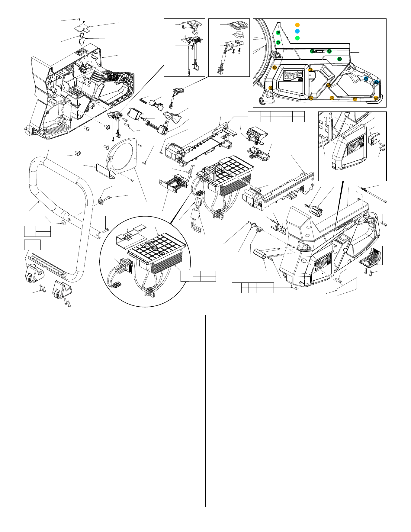
FIG. PART NO. DESCRIPTION OF PART NO. REQ.
28 06-82-0032 M4 x 12mm Pan Hd. ST T-20 Screw (4)
30 06-81-0041 M6 x 15mm Pan Washer Hd. Mach. Sc. (4)
31 05-78-0088 M2.6 x 6mm Flat Hd. ST Phillips Screw (2)
32 42-92-0050 Coin Cell Cover (1)
34 --------------- 3V Coin Cell Battery (1)
35 22-80-0015 Coin Cell PCBA (1)
36a 22-80-0020 Bluetooth Board Holder (1)
36b 22-80-0025 Bluetooth Board (1)
36c 05-88-0083 M2.2 x 6mm Pan Hd. Plastite T-8 Scr. (4)
37a 31-15-0034 Arm Button Housing (1)
37b 31-15-0043 Arm Button Cap (1)
37c 22-80-0030 Arm Board (1)
38 --------------- Right Handle Housing (1)
39 31-92-0026 Primary Trigger (1)
40 28-06-0011 Switch Holder-Right (1)
41 40-50-0197 Compression Spring (1)
42 31-92-0028 Secondary Trigger (1)
43 23-66-0199 Signal Switch (1)
44 31-05-0018 Bae (1)
45 06-82-1080 M3 x 14mm Pan Hd. ST T-10 Screw (9)
46d --------------- Battery Interface-Right (1)
46j --------------- Battery Interface-Left (1)
46k --------------- Battery Terminal Wiring Assembly (1)
47 --------------- Bale Handle (1)
48 22-68-0031 Wire Cover (1)
49 22-80-0031 Main Board (1)
50 --------------- Ferrite Bead (1)
51 42-86-0020 Connector Clip (1)
52 05-78-0033 M5 x 20mm Pan Hd. T-25 Mach. Screw (1)
54, 06-82-0152 8
55, 06-82-0029 2
58, 05-88-0087 5
84
37a
37b
37c
36c
(2x)
36a
36b
36c
(2x)
31
(2x)
34
32
35
38
41 42
39
43
45
(3x)
46d
107
103
46j
106
45 46d 46j 46k
100 103 107
57 86 84
58
(5x)
55
(3x)
56
55
(2x)
54
(7x)
120
57
40
55
(2x)
45
(3x)
30
(4x)
74
47
88
52
100
90
50
44
82
80
45
60
59
45
(2x)
81
83
54
51
5453
99
54
54
(4x)
121
47 52
53 88
110
35 43 48
49 51 54
98
28 38 54 55
58 84 85 120
48 49
46k
28
(4x)
85
87
55
(2x)
53 45-88-0169 Isolation Washer (1)
54 06-82-0152 M5 x 22mm Pan Hd. ST T-25 Screw (14)
55 06-82-0029 M5 x 16mm Pan Hd. ST T-25 Screw (8)
56 42-38-0023 Rear Foot (1)
57 05-70-0010 M4 x 16mm Flat Hd. ST T-20 Screw (2)
58 05-88-0087 M5 x 115mm Pan Hd. PT T-20 Screw (5)
59 49-96-0021 5mm Hex Key (1)
60 49-96-0031 Socket Wrench (1)
74 14-32-0016 Spark Guard (1)
80 31-15-0057 Spring Cover (1)
81 31-15-0059 Retension Cover (1)
82 28-28-0035 Spring Plate (1)
83 42-92-0073 Rubber Retainer (1)
84 --------------- Left Handle Housing (1)
85 --------------- Side Cover (1)
86 22-68-0021 Switch Holder-Left (1)
87 43-62-0051 Bale Handle Mount (1)
88 31-86-0011 Isolated Screw Spacer (1)
90 --------------- Wire U Assembly (1)
98 14-34-0017 Housing Service Kit (1)
99 42-92-0074 Wheel Service Kit (1)
100 --------------- Battery Ejector Assembly (1)
103 --------------- Battery Latch Release Assembly (1)
106 31-06-0018 Battery Interface Assembly (1)
107 --------------- Latch Assembly (1)
110 14-20-0174 MX PCBA Electronics Assembly (1)
120 12-20-0182 Service Nameplate (1)
121 14-34-0038 Bale Handle Assembly (1)
FIG. PART NO. DESCRIPTION OF PART NO. REQ.
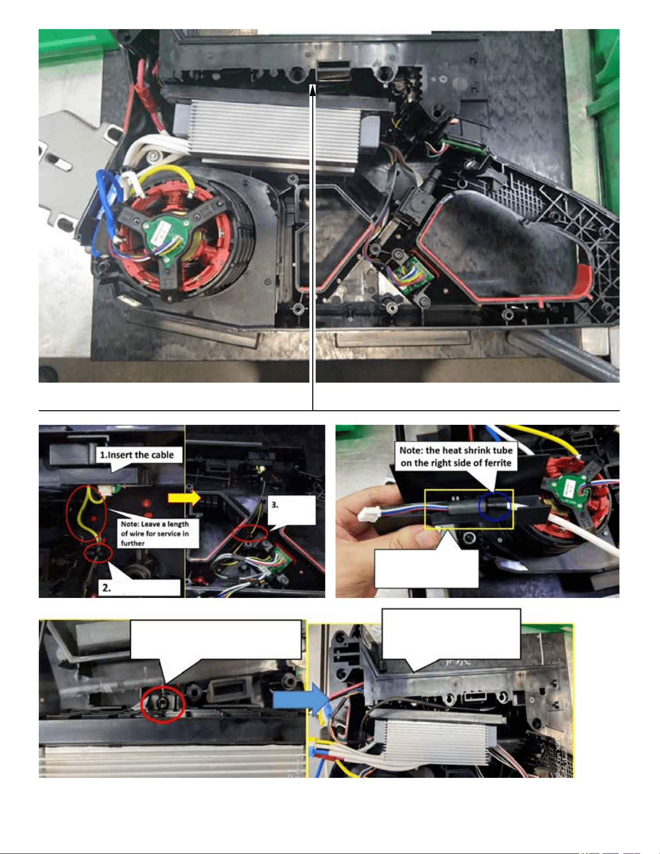
Trap the wire
Trap the
wire
4. Insert the ferrite
to wire cover
5. Screw PCBA to handle
6. Install the Battery
Interface Assembly
Page 3
Put the Battery
wire in this room
Page 4
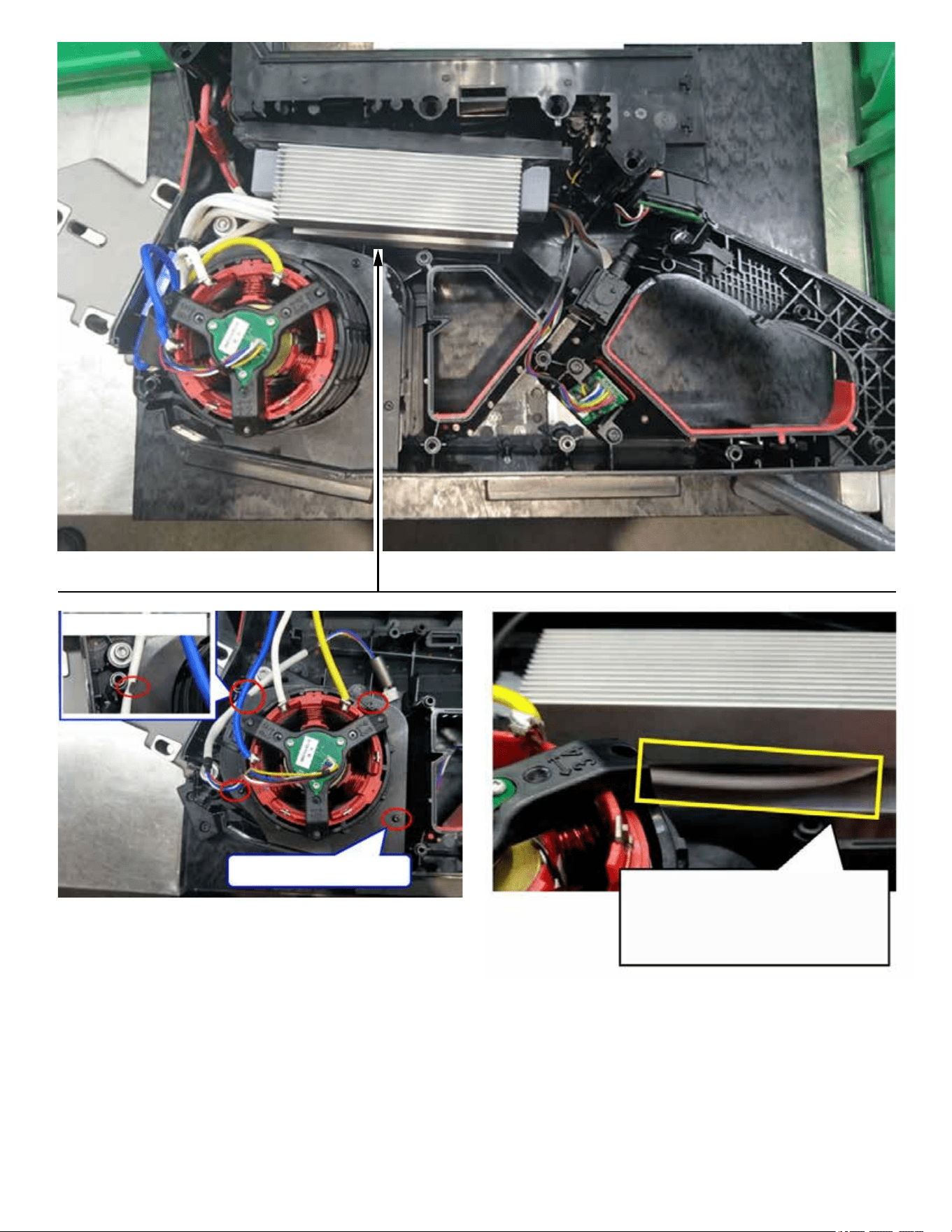
1. Fix hall sensor wire
2. Tighten the screws
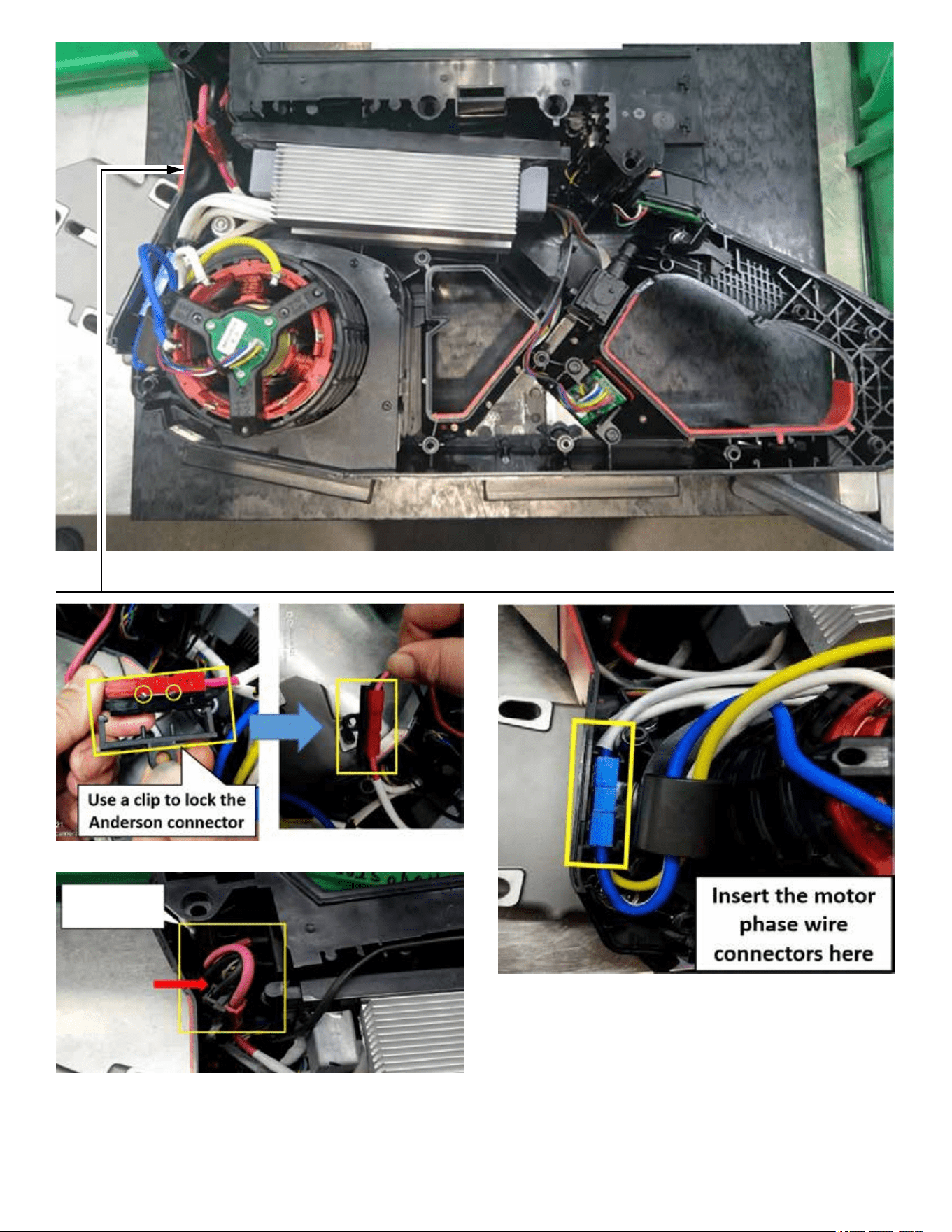
All motor phase wires should
be hidden behind the PCBA
Page 5
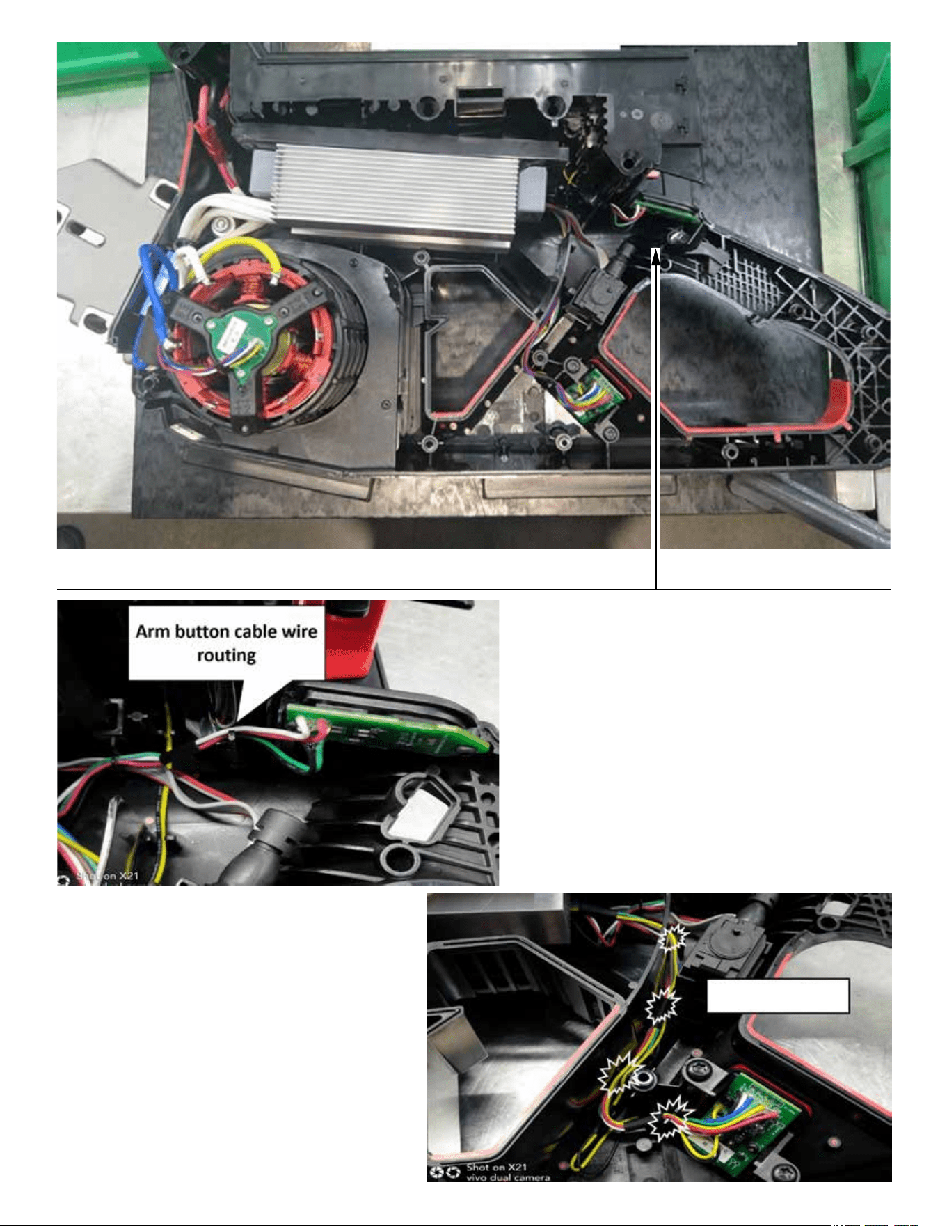
Trap the wires
Page 6