

1
● Prohibit the surface rolling machines for concrete, asphalt, wear-resistant epoxy resin or
ground outside uses.
● Prohibit improper training of personnel to operate the equipment, the operation of the
equipment and personnel must be familiar with the associated potential risks and dangers
● Prohibit touching engine or silencers, when the machine was operating, or has just been
switched off, these sites fever, may cause combustion.
● And the prohibition did not recommend the insert, annex for the device. Could damage
equipment or cause injury to the operator.
●Prohibit operation without shields machines. And the skin was exposed pulley lead to serious
injury hazards.
●Prohibit left when the machine was operating.
●Prohibited in indoor or in a confined region. Unless EXHAUST FAN or exhaust pipe through the
provision of adequate ventilation, engine Emission of toxic gases contains carbon monoxide,
which would cause shock exposure and possible death.
●Must keep hands and feet and loose clothing away from the equipment's moving parts.
●In the operation of equipment must wear protective work clothing, such as: goggles or safety
glasses to protect against flying glasses of injury.
●Must use milling machine, the operator is familiar with the confirmation security measures and
operating skills.
●We must always close the fuel valve engine when milling machine is not working.
●Must be stored in a clean and dry will not be close to the children.
When not in use, it is necessary to preserve equipment.
● Must be reasonable in accordance with the operating procedures of the safety devices milling
machine, not to modify or damage to safety devices.
Safety while using Internal Combustion Engines
There are dangers while operating or refueling the internal combustion engine. Serious
damage may be led if the safety regulations described as follows are not obeyed.
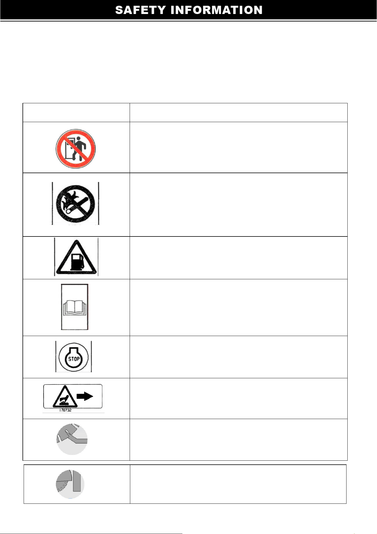
SAFETY LABELS
Cutting machine used international generic icon labels, as follows:
Label
Meaning
Warning! To prevent hearing loss, in the
operation with good hearing protectors.
Harm! The engine of carbon monoxide released
only in a well-ventilated the operation. Reading
a manual, sparks or flame of burning. Increase
fuel engines to be shut down.
Gasoline fuels.
Attention! In the operation of the machine, read
and understand the manuals provided by the
operator. Otherwise, I will hurt or harm others.
Turn the engine off before refueling.
Warning! HOT surface.
Do not put hands into the rotating cutter blades
。
2
When cutting, the machine can not have road
blocks and other former obstacles

OPERATION
1. The oil level check
Put dipstick into the oil port, do not rotate, take out to check oil level, if the engine oil level
is low add oil to the recommended upper limit at the dipstick.
2. Air Filter
Check the air filter element, ensure it is clean and in good condition. If necessary, clean or
replace components.
3. Fuel
Recommended use of gasoline engines. Prohibit the use of oil / gasoline mixture or dirty
gasoline; avoid dirt, dust or water to get the fuel tank. Caution: prohibit the use of gasoline
alternatives; they are harmful effects of fuel system components.
Cutting machine operator
1. Start the engine, load 3-5 minutes, then transferred to the appropriate location of the
throttle.
2. Rotate the hand wheel to slow down the blade to the desired depth of cut (cutting
machine in this model the depth range), rotary drive up stopper, the cutting depth lock.
Slowly push the machine for cutting.
Fitting the blade
Set he machine in the high position
Swift off (A); disconnect the water pipe from the blade guard.
Lift up guard (B) (FIG. 1)
Take care about the direction of rotation which is shown by an arrow on one of the faces
(direction of rotation on the right side of the guard) Make sure the contact faces of
flanges (B and C) of blade and the axle are clean.
Firmly lock screw using the spanner supplied with the machine whilst immobilizing the
blade by hand. (C)
Replace the protection guard (B).
Close the guard water tap. (A)
Reconnect the water pipe.
Replace all protective covers for your safety and that of other persons. Note: how to adjust the
‘zero’ according to the diameter of blade:
3
Check before starting
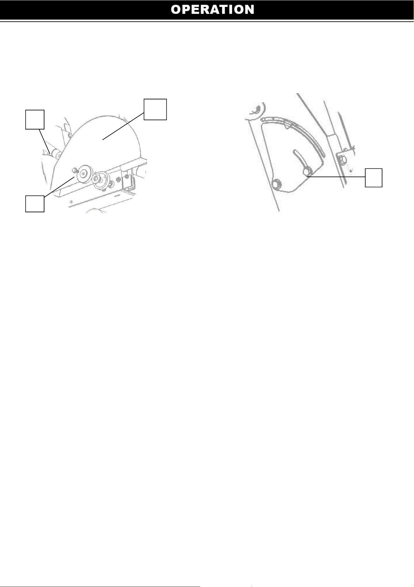
The blade must be closed to the floor.
Loosen the screw (D) (FIG 2)
Line up the ‘zero’ with the pointer, then tight the screw.
FIG 2
FIG 1
Danger: risk of injury.
Always pay extreme care and attention to the preparation of the machine before
starting up.
Remove all adjustment tools and wrenches from floor and machine.
Always keep blade guard in place.
Fill the tank with water, or connect with the water network.
Mark the floor by drawing a line in the place to be cut.
Fold down the front guide and position the machine so that the guide and the
blade line up with the mark.
Engine:
Starting the engine: refer to the instructions in the manufacturer’s service manual.
a) Open the water inlet tap.
b) Increase the engine speed to maximum.
c) Lower the blade to the desired depth indicated on the side scale on the ratchet placed
on the side. We recommend a slow descent to avoid stalling the engine.
Note: ensure that the water supply is abundant, when cutting wet.
Stopping the machine
a) Low the black wheel and turn the wheel to release the blade from the groove.
b) Turn off the water supply
c) Allow the engine to turn at low speed
A
B
C
D
4
Starting Up

Stop the engine (consult the engine maintenance manual)
Maintenance
‘Engine Maintenance’: refer to the engine maintenance booklet.
a) After use, clean the machine.
b) Lubrication: apply a moderate amount of bearing lubricant to the nipples in the
depth adjustment chassis (depending on the frequency of use)
c) The spindle bearings must be greased after 8 hours of use, with a grease gun by
pumping three to five times the grease into the greaser of the bearings.
d) Every 40 hours grease: depth control adjustment screw.
‘Air Filter’
a) Read engine owners manual for maintenance intervals. For extremely dusty
conditions you may have to clean the air filter element 2 to 3 times a day.
b) Replace any damaged filters or gaskets.
Store in a safe place out of reach of children
Remove all adjustment tools and wrenches.
Store diamond tool in a safe place so it cannot be bent or damaged.
Motor Belt Tension
After several hours of use it may be necessary to adjust the tension of the belts
(moderately). To do these proceed as follows:
a) Release the screws fixing the motor to the chassis.
b) Turn the tensioning screw (E) at the front of the machine one quarter turn; this screw
pushes the motor backwards. (FIG. 3)
c) At normal tension, counter lock the nut of the screw.
d) Relock the motor fixing screws.
Note: never set belts beyond original tension.
FIG 3
5

Important Recommendations
a) Periodically tighten all nuts and bolts, particularly after the first few hours of
operation.
b) Check the tension of the belt, tighten it as instructed
c) When storing the machine, we recommend removing the blade and storing it carefully
d) Check that the blade is properly sprayed by inspecting the holes in the fork regularly
e) Tighten the blade firmly
f) Make sure the contact faces of flanges, blade and axle are clean. The manufacturer
declines all responsibility for loss or damage resulting from misuse or any modification,
alteration or powering that does not conform to the manufacturer’s original specifications.
Cutting Machine Caution:
1. Start the engine before the switch to open flame, go to the fuel valve open (ON)
position, place the throttle closed (Close) position (Note: If the state of the engine as
heat or high temperature, the engine starts to throttle open). After the engine starts,
slowly move the throttle open (OPEN) position.
2. Before you start the engine, cutting blade should be removed from the ground, after
the engine runs, adjust lower in the slowly toward the cutting depth, then lock the
cutting depth. Avoid rapid downward adjustment cutting depth
3. the depth of each cut should be determined according to the actual cutting conditions
on the ground, the different hardness of the ground effect for this model is also
very important, the higher the hardness of the depth of a cut should be smaller,
while the road speed of the machine should slow down, Order to be conducive to the
efficient work of cutting machine
4. if cutting depth too deep, the engine emits unusual sounds, machinery easily to
cause injury, the operator has a security threat, then raise the blade should be timely to
re-adjust the cutting depth
5. Once cutting blade does not cut capacity should be worn out replace them with
new cutting discs, continue using the old blade will damage the blade shaft and other
components, severe fracture, cutting blade will break
6
6. After each use, clean the cutting machine in a timely manner, in accordance with
the maintenance and maintenance methods, please do not use fatigue
7. prohibited people (two and above) operating the same cutting machine, the
machine work in order to avoid confusion and unnecessary harm

Product Parameters
Maintenance of the Periodic Table
The following figure shows the basic cutting machine and engine maintenance
method:
Engine maintenance information please refer to engine manual.
Model
61069
Engine
Loncin G420 14HP with
CARB
Cutting Dept (in) 7
Blade Diameter (in) 12-20
Water Tank(L/us gal) 25/6.6
Rotating Speed(rpm) 3600
Blade Guard Type Bolted
Depth Control Handle wheel
Movement Type Walk behind
Overall Dimension (in) 48 × 24 × 39
Shipping Size (in) 37 × 24× 43
Operating Weight (lb) 247
Shipping Weight (lb) 264
7

Troubleshooting
Problems How to solve
Cutting machine is not
working at full speed
1. Removal of engine cylinder and cylinder head coke
2. Engine speed is low, adjust the speed
3. Clean or replace air filter
4. Check both sides of the blade shaft bearings for wear, damage, or grease (oil)
less than
5. In the cold season, warm the engine idle for 3-4 minutes
Check belts for wear, damage, or not enough tension
The engine is running but
with poor result
1. Check the cutting blades wear
2. Check the tension of belt
The blade stop
running when cutting
1. Check the tension of belt
2. Gasoline is not enough, the engine shut down
3. Cutting too fast or too slow
CONCEPT
ITEM
BEFORE
START
AFTER THE
FIRST 20
HOUR
EVERY 2 WEEK EVERY MONTH
EVERY THREE
MONTH
Check the fuel level
●
Check the engine oil
●
Check the fuel pipe
●
Check the air filter
●
Check the external
fastening screw
●
Clean air filter
●
Grease the cam follower
●
Replace engine oil
●
●
Check the drive belt
●
Clean cooling system
●
Check the spark plug
●
Clean sediment cup
●
Check and adjust valve clearance
●
8

Handling and Transport
a) Switch off the disk prior to moving the machine on job site
b) Remove the disk prior to hoisting, loading, unloading and transporting the machine
on job site.
c) Height of the handle-bar adjustable by pivoting
d) To position the floor saw on the site, simply push it. It will move easily on its four
wheels without starting the engine.
e) For transporting by vehicle or by any kind of lifting gear, there is a factory-fitted
hoisting point on the machine.
STORAGE
If the milling machine storage more than 30 days:
1. Replace the engine oil.
2. Drain the fuel from the engine.
3. Remove the spark plugs, the 1 / 2 oz (15ml) of SAE30 engine oil poured into
the cylinder. Spark plugs installed, turn the engine to make the oil spread. See engine
manual.
4. Clear cylinder, cylinder head heat sink, flywheel cover, rotating screen and muffler
area of dust.
5. To save space, the handle into its repository.
6. Milling machine and engine cover, stored dry and clean place.
9
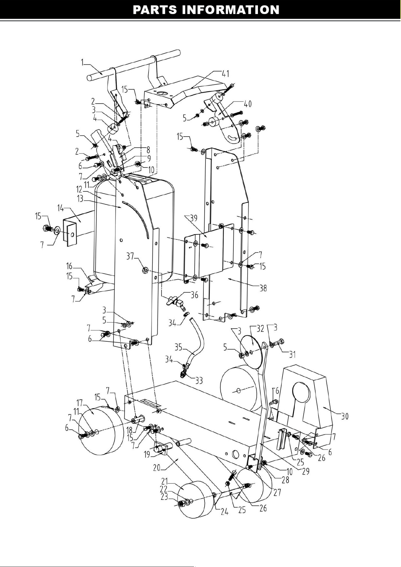
Frame Assembly
11

FRAME PARTS LIST
ITEM PART NO. QTY DESCRIPTION
1 D400-18-000 1 Handle
2 20101-0016 4 Hex screw M8X45
3 20103-0005 12 Φ8 dish mat
4 D400-18-007 4 Rubber pad 1
5 20102-0029 6 Nut M8
6 20101-0023 8 Hex screw M10X25
7 20105-0002 35 φ10 spring pad
8 D400-13 1 Limiter
9 20101-0025 1 Hex screw M10X35
10 20102-0030 2 Nut M10
11 20103-0010 4 Φ10 Gland
12 21000-0001 1 Water tank
13 D400-05-000 1 Right side of the blard
14 D400-04 1 Water tank holder
15 20101-0022 17 Hex screw M10X20
16 D400-15 1 Block tank
17 20300-0003 2 Rear wheel
18 D400-04 2 Rear axle
19 D400-03 2 Clip
20 D400-02 1 Little bottom
21 20300-0002 2 Front wheel
22 20103-0013 2 φ16 washer
23 20102-0033 2 Nut M16
24 D400-02-004 1 Front axle
25 20102-0004 3 Nut M10
26 20101-0029 2 Hex screw M10X60
27 20101-0024 1 Hex screw M10X30
28 20103-0008 4 Φ10 dish mat
29 D400-23 1 Index rod
30 D400-22 1 Belt cover
31 20101-0012 1 Hex screw M8X25
32 D400-24 1 Road guide disc
33 20800-0005 1 Water pipe switch
34 20800-0006 2 Hose clamp
35 20800-0007 1 Water pipe
36 20800-0008 1 Water valve
37 20800-0009 1 Copper nut for water valve
38 D400-06-000 1 Left panel
39 D400-14-000 1 Panel
40 D400-18-005/006 2 The following side
41 D400-12 1 Operating panel
12
13
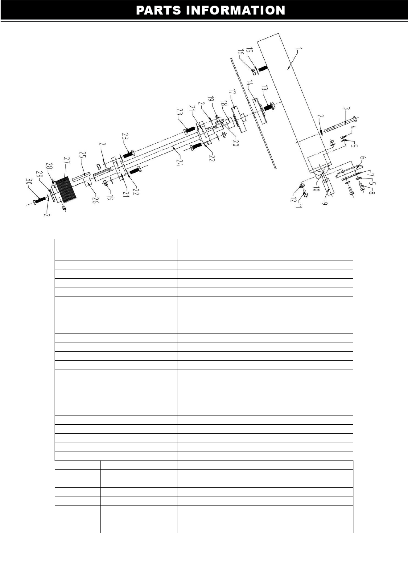
Blade Assembly
ITEM PART NO. QTY DESCRIPTION
1 D400-21 1 Blade cover
2 20105-0002 6 Φ10 dish mat
3 20101-0035 1 Hex screw M10X110
4 20102-0028 2 Nut M6
5 20103-0004 4 Φ6 Gland
6 D400-21-006 1 Rubber fender
7 D400-21-007 1 Tabletting
8 20101-0003 1 Hex screw M6X20
9 20800-0004 1 Water pipe switch
10 D400-21-004-00 1 Shower pipe
11 20101-0011 1 Hex screw M8X20
12 20105-0001 1 Φ8 dish mat
13 20101-0069 1
14 D400-20-005 1 Blade pressure plate(up)
15 20103-0010 1 Gland(Φ10xΦ28x3)
16 20102-0030 1 Nut M10
17 D400-20-004 1 Blade pressure plate(down)
18 D400-20-008 1 Put circle 1
19 20102-0004 4 Nut M10
20 20110-0004 1 Blade pressure plate key6x6x12
21 20402-0012 2 Blade shaft bearings
22 20103-0008 4 Φ10 dish mat
23 20101-0025 4 Hex screw M10X35
24 D400-20-001 1 Blade shaft
25 20110-0013 1
Multi-wedge wheel key blade
shaft8x7x55
26 D400-20-008 1 Put ring 2
27 D400-20-002 1 Multi-wedge blade wheel shaft
28 20101-0093 2 Hex screw M8x12
29 20103-0020 1 Φ10 Gland
30 20101-0023 1 Hex screw M10x25
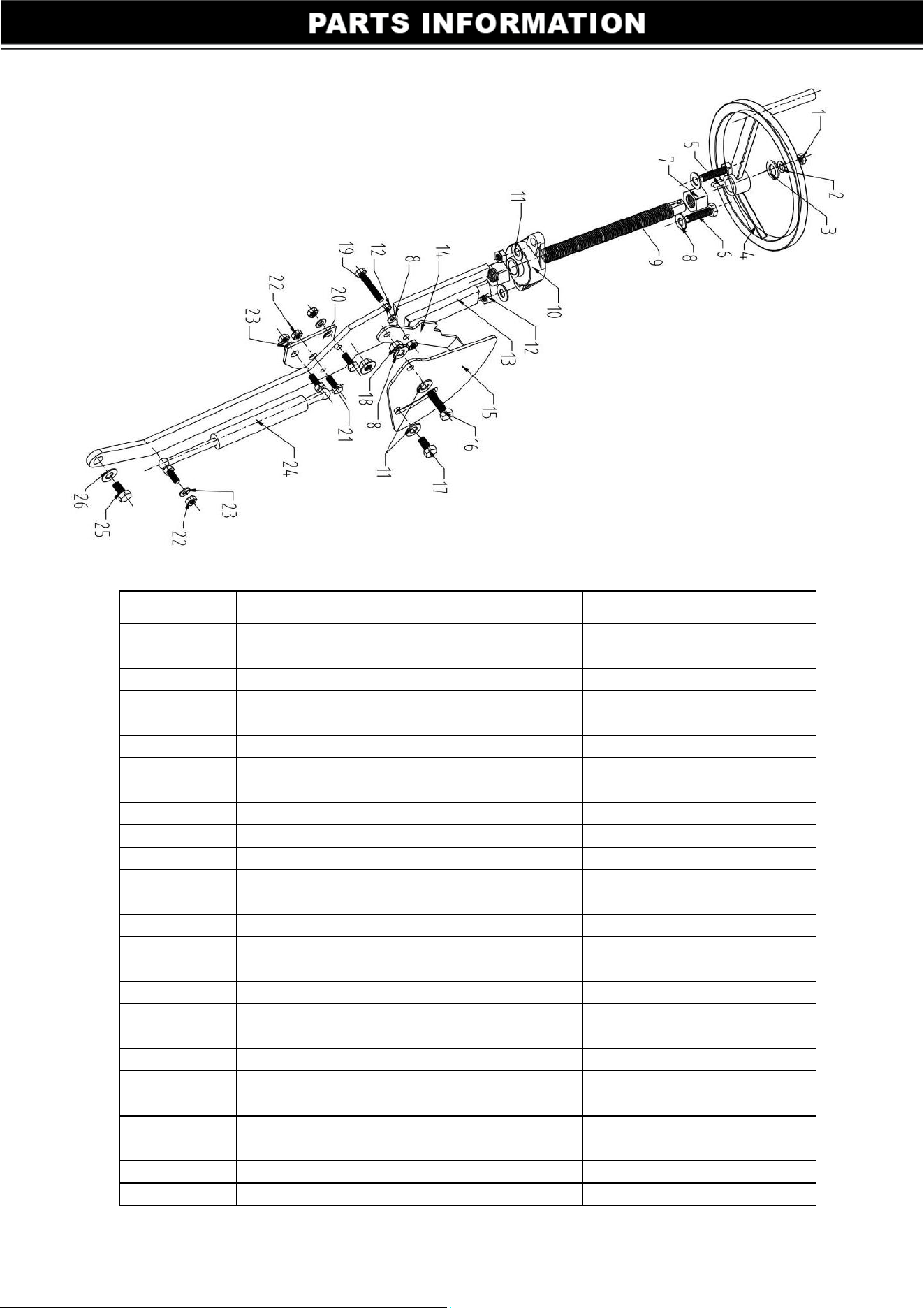
Adjustment Component
ITEM PART NO. QTY DESCRIPTION
1 20101-0011 1 Hex screw M8X20
2 20104-0004 1 φ8 dish mat
3 20103-0007 1 φ8 Gland
4 20200-0003 1 Adjustment dial
5 20110-0005 1 key 6x6x20
6 20101-0024 2 Hex screw M10X30
7 D400-09-003 2 Nut M20
8 20103-0008 3 φ10 dish mat
9 D400-19 1 screw
10 20402-0001 1 universal bearing
11 20105-0002 4 Φ10 dish mat
12 20102-0004 4 Nut M10
13 D400-09-002 1 Drawing board
14 D400-08 1 Scale pointer
15 D400-007 1 Dial
16 20101-0024 1 Hex screw M10X30
17 20101-0022 1 Hex screw M10X20
18 20102-0030 1 Nut M10
19 20101-0128 1 Hex socket screw M10x35
20 D400-10 1 Fixed plate
21 20101-0012 2 Hex screw M8X25
22 20102-0029 3 Nut M8
23 20103-0005 6 Φ8 dish mat
24 20600-0001 1 Gas spring
25 20101-0037 1 Hex screw M12X20
26 20105-0003 1 φ12 dish mat
14
15