
PLANNING GUIDE
INTEGRATED REFRIGERATION, 1.88M HIGH
60cm Series 9 Integrated Refrigerator Freezer, Ice & Water | RS6019BRU1
60cm Series 9 Integrated Dual Zone Refrigerator | RS6019S2R1
60cm Series 9 Integrated Dual Zone Freezer | RS6019F2L1
60cm Series 9 Integrated Triple Zone Refrigerator | RS6019S3RH1
60cm Series 9 Integrated Triple Zone Freezer, Ice | RS6019F3LJ1

The models shown in this Planning Guide may not be available in all markets and are subject to change at any time. Product specifications may vary from those shown. This Planning Guide should not be used as installation guidance for any
product. Further information is required to safely and correctly install the products featured here. Specific installation guidance will be available on our website fisherpaykel.com
© FISHER & PAYKEL LIMITED 2024 PAGE 290002833C PLANNING GUIDE REFRIGERATION - VERSION C - OCTOBER 2024
PLANNING GUIDE | INTEGRATED REFRIGERATION, 1.88M HIGH
This comprehensive Planning Guide provides you with the framework and tools to achieve your desired design outcome with Fisher & Paykel appliances. In this guide, you will
find a range of conceptual, detailed and dimensional product information to bring your ideas to life and create spaces that truly reflect your vision.
CONCEPT DESIGN PAGE DEVELOPED AND DETAILED DESIGN PAGE PAGE
Design Choices
Purchase Decision 5
Accessories 6
Specification Guides
Integrated Refrigeration 8
Data Sheets
Integrated Refrigerator Freezer 12
Integrated Refrigerator Freezer, Custom Panel 13
Integrated Refrigerator and Freezer 14
Integrated Refrigerator and Freezer, Custom Panel 15
Custom Panels
Integrated Refrigerator Freezer 17
Integrated Refrigerator and Freezer 18
Planning Considerations
Product Dimensions 20
Panel and Toe Kick Dimensions 21
Dual and Triple 22
Gap Clearances 23
Toe Kick Detail 24
Hinge Articulation 25
Door Opening Clearance 26
Services
Service Area and Electrical 29
Hose and Cord Length 30
Handle Data Sheets
Square Fine Handle Kit 32
Round Handle Kit 33
Classic Handle Kit 34
Professional Handle Kit 35
Square Fine Handle 36
Round Handle 37
Classic Handle 38
Professional Handle 39
SUPPORT
For additional design planning and installation support please contact
the Fisher & Paykel design support team.
designsupport@fisherpaykel.com
<< CONTENTS
i
i

© FISHER & PAYKEL LIMITED 2024 PAGE 390002833C PLANNING GUIDE REFRIGERATION - VERSION C - OCTOBER 2024
DESIGN CHOICES
Design Choices
The models shown in this Planning Guide may not be available in all markets and are subject to change at any time. Product specifications may vary from those shown. This Planning Guide should not be used as installation guidance for any
product. Further information is required to safely and correctly install the products featured here. Specific installation guidance will be available on our website fisherpaykel.com
© FISHER & PAYKEL LIMITED 2024 PAGE 490002833C PLANNING GUIDE REFRIGERATION - VERSION C - OCTOBER 2024
DESIGN CHOICES | PURCHASE DECISION RS6019BRU1 | RS6019S2R1 | RS6019S3RH1 | RS6019F2L1 | RS6019F3LJ1
INTERIOR
White and stainless steel
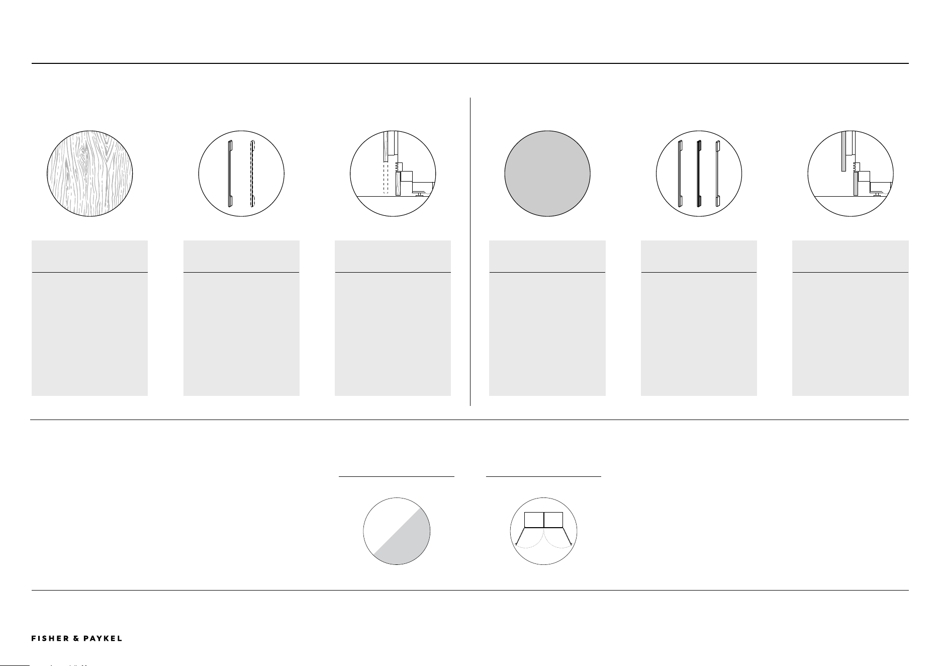
CUSTOM PANEL OPTIONS STAINLESS STEEL PANEL OPTIONS
PANEL
Custom door panels can be
adjusted in height to achieve
the desired visual toe kick,
and their width can also be
modified to achieve smaller
gap clearances.
HANDLES AND
ACCESSORIES HANDLES
Select Fisher & Paykel handles
or customize handles to match
your kitchen style.
ASSISTED OPENING
ACCESSORY: Pull or push-to-
open functionality, .
TOE KICK
The distance from the bottom
of the door panel to the floor
(visual toe kick) can range
from 15mm to 150mm.
PANEL
Set Stainless steel door panel
sizes.
ACCESSORIES HANDLES
Select Fisher & Paykel
handles.
TOE KICK
The stainless steel toe kick
panel stands at 100mm high
and is available in different
lengths for single, dual, and
triple installations.
HINGING
Left or right*
ALL MODELS
*All models come with
hinge conversion kit
<< CONTENTS
The models shown in this Planning Guide may not be available in all markets and are subject to change at any time. Product specifications may vary from those shown. This Planning Guide should not be used as installation guidance for any
product. Further information is required to safely and correctly install the products featured here. Specific installation guidance will be available on our website fisherpaykel.com
© FISHER & PAYKEL LIMITED 2024 PAGE 590002833C PLANNING GUIDE REFRIGERATION - VERSION C - OCTOBER 2024
refrige 1 dual and 1 triple zone
freezer 1 dual and 1 triple zone
DESIGN CHOICES | INTEGRATED REFRIGERATION, 1.88M HIGH
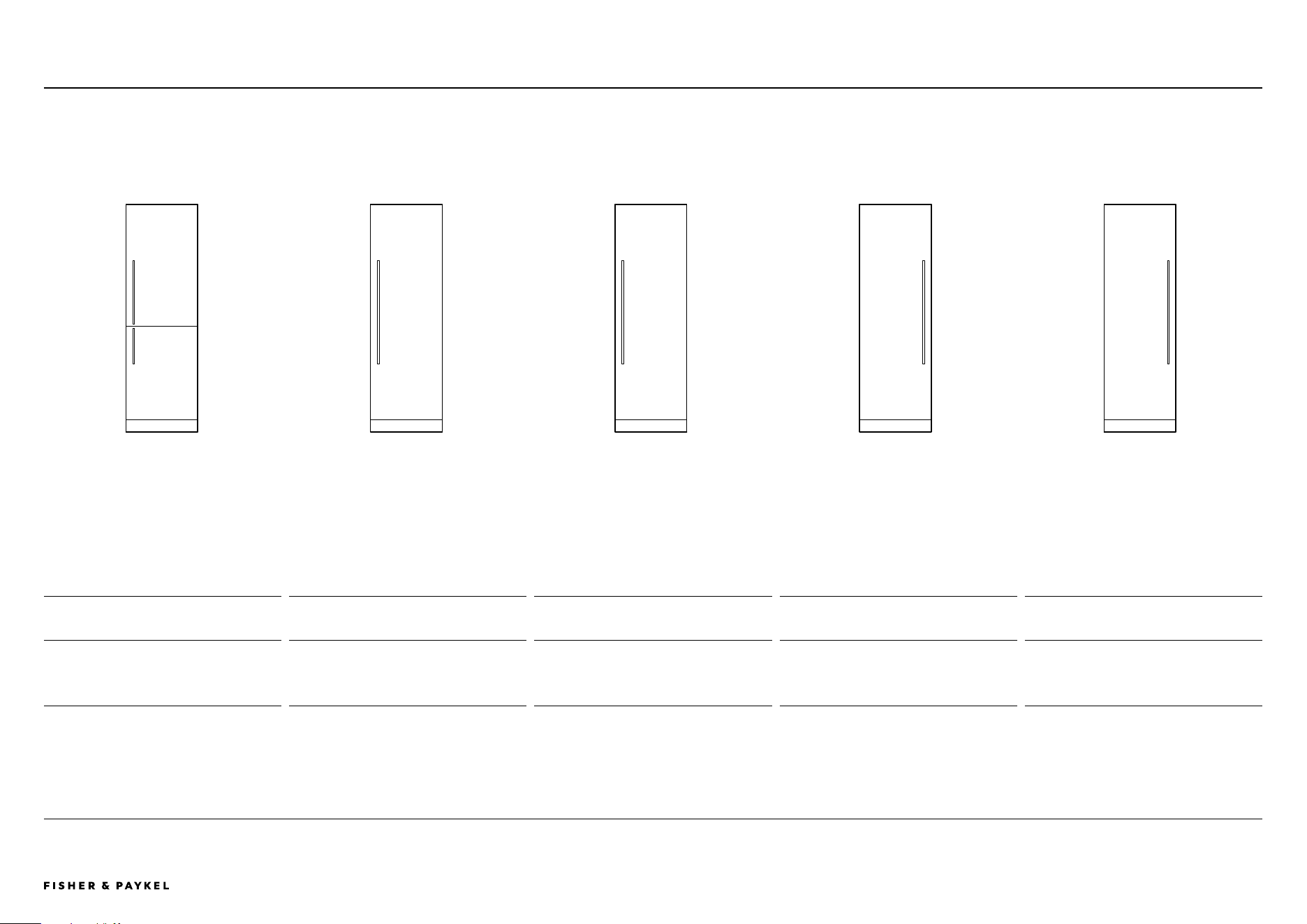
INTEGRATED DUAL ZONE REFRIGERATORINTEGRATED REFRIGERATOR FREEZER,
ICE & WATER
Product Hinge Model Product Hinge Model Product Hinge Model Product Hinge Model Product Hinge Model
1 60cm Series 9 Integrated
Refrigerator Freezer
Right* RS6019BRU1
2 60cm Series 9 Integrated
Dual Zone Refrigerator
Right* RS6019S2R1
3 60cm Series 9 Integrated
Triple Zone Refrigerator
Right* RS6019S3RH1
4 60cm Series 9 Integrated
Dual Zone Freezer
Left* RS6019F2L1
5 60cm Series 9 Integrated
Triple Zone Freezer
Left* RS6019F3LJ1
A slim profile, perfect for compact kitchens, or pair
with other Integrated models for generous chilled and
frozen storage
Pair with the Integrated Dual Zone Freezer for the
ultimate kitchen solution – this model features two
independent food zones taking cooling flexibility to a
new level.
Pair with the Integrated Triple Zone Freezer for the
ultimate kitchen solution – this model features three
independent food zones taking cooling flexibility to a
new level.
Pair with the Integrated Dual Zone Refrigerator for
the ultimate kitchen solution – this model features two
independent food zones taking cooling flexibility to a
new level.
Pair with the Integrated Triple Zone Refrigerator for the
ultimate kitchen solution – this model features three
independent food zones taking cooling flexibility to a
new level.
*Comes with hinge conversion kit.
RS6019BRU1 | RS6019S2R1 | RS6019S3RH1 | RS6019F2L1 | RS6019F3LJ1
Purchase Decision
INTEGRATED TRIPLE ZONE REFRIGERATOR INTEGRATED DUAL ZONE FREEZER INTEGRATED TRIPLE ZONE FREEZER,
ICE
1 2 3 4 5
<< CONTENTS
The models shown in this Planning Guide may not be available in all markets and are subject to change at any time. Product specifications may vary from those shown. This Planning Guide should not be used as installation guidance for any
product. Further information is required to safely and correctly install the products featured here. Specific installation guidance will be available on our website fisherpaykel.com
© FISHER & PAYKEL LIMITED 2024 PAGE 690002833C PLANNING GUIDE REFRIGERATION - VERSION C - OCTOBER 2024
PANELS TOE KICK JOINER KIT HANDLES
STAINLESS STEEL LEFT HINGE RIGHT HINGE STAINLESS STEEL HANDLE TYPE FINISH
SINGLE DOOR
MODLE
TOP AND BOTTOM
HANDLE KITS
1 Refrigerator Freezer Stainless
Steel Panels*
RD6019BL RD6019BR
4 Single toe kick
AKRS06010 Single Installation No joiner kit required
Contemporary Square Fine
Aluminium
1 AHD5RDSF 5 AHD5RDB19
2 Refrigerator Stainless Steel
Panel**
RD6019 RD6019
4 Dual toe kick
AKRS12010 Dual Installation
AJRS19LR
(1 kit required)
Black
1 AHD5RDSFB 5 AHD5RDB19B
3 Freezer Stainless Steel Panel**
RD6019 RD6019
4 Triple toe kick
AKRS18010 Triple Installation
AJRS19LR
(2 kits required)
Contemporary Round Aluminium
2 AHSRDSF 6 AHSRDB19
Classic Aluminium
3 AHCLRDSF 7 AHCLRDB
Professional Round Aluminium
4 AHP3RDSF 8 AHP3RDB19
Assisted Opening
(custom panels only)
Check fisherpaykel.com for availablity
*Two panels supplied in panel kit.
**One panel supplied in panel kit.
Note: 1 joiner kit included with freezer models
RS6019F2L1 and RS6019F3LJ1.
Note: For measurements of the handles, refer to 'Handle Data Sheets' section of this
Planning Guide.
5
6
7
8
1
2
3
4
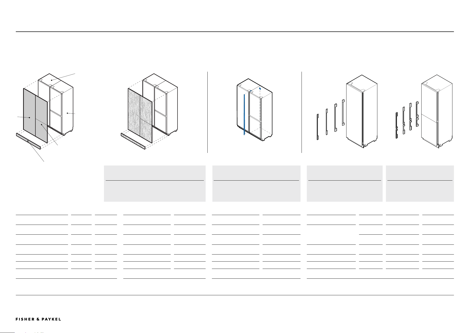
STAINLESS STEEL PANEL AND TOE KICK CUSTOM PANEL AND TOE KICK
JOINER KIT
(FOR MULTIPLE PRODUCT
INSTALLATION)
SINGLE DOOR HANDLES DOUBLE DOOR HANDLE KITS
Accessories
SPECIFICATION GUIDE | ACCESSORIES RS6019BRU1 | RS6019S2R1 | RS6019S3RH1 | RS6019F2L1 | RS6019F3LJ1
RS6019BRU1
RS6019S2R1,
RS6019S3RH1,
RS6019F2L1,
RS6019F3LJ1
1
2
3
4
CUSTOM DOOR PANELS
Custom door panels and toe kick to be
manufactured and fitted by cabinet maker.
SINGLE DOOR
One handle supplied in handle kit.
DOUBLE DOOR
Two handles supplied in handle
kit.
JOINER KIT
Each kit comes with four brackets and one
trim.
<< CONTENTS

© FISHER & PAYKEL LIMITED 2024 PAGE 790002833C PLANNING GUIDE REFRIGERATION - VERSION C - OCTOBER 2024
SPECIFICATION GUIDE
Specification Guides
The models shown in this Planning Guide may not be available in all markets and are subject to change at any time. Product specifications may vary from those shown. This Planning Guide should not be used as installation guidance for any
product. Further information is required to safely and correctly install the products featured here. Specific installation guidance will be available on our website fisherpaykel.com
© FISHER & PAYKEL LIMITED 2024 PAGE 890002833C PLANNING GUIDE REFRIGERATION - VERSION C - OCTOBER 2024
RS6019F3LJ1, RS6019S3RH1 and RS6019BRU1.
Integrated Refrigeration
SPECIFICATION GUIDE | INTEGRATED REFRIGERATION, 1.88M HIGH
RS6019F3LJ1, RS6019S3RH1 and RS6019BRU1.
RS6019BRU1 | RS6019S2R1 | RS6019S3RH1 | RS6019F2L1 | RS6019F3LJ1
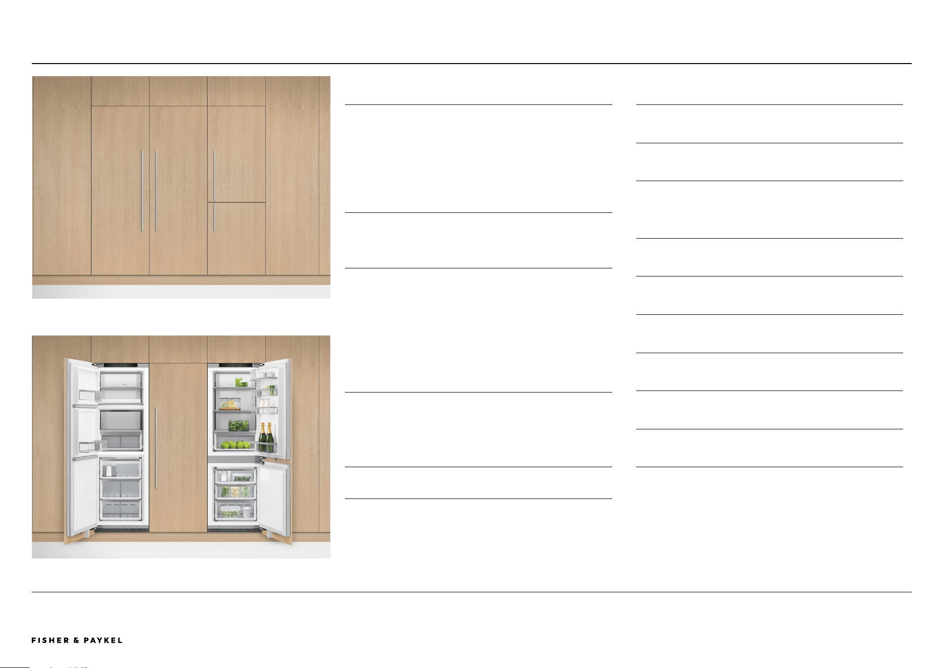
OVERVIEW
These slim profile Integrated Refrigerators and Freezers are
perfect for compact kitchens, or pair them together for
generous chilled and frozen storage. Features two or three
independent zones with ActiveSmart™ technology for
optimal freshness, and bright LED lighting. With options for
ice makers, water dispensers and joining kits these models
provide the ultimate flexibility.
PRODUCTS
RS6019BRU1 - 60cm Series 9 Integrated Refrigerator
Freezer, Ice & Water
RS6019S2R1 - 60cm Series 9 Integrated Dual Zone
Refrigerator
RS6019S3RH1 - 60cm Series 9 Integrated Triple Zone
Refrigerator
RS6019F2L1 - 60cm Series 9 Integrated Dual Zone Freezer
RS6019F3LJ1 - 60cm Series 9 Integrated Triple Zone Freezer,
Ice
SERIES & STYLE
Series 9
Integrated
FEATURES
1
Customize with kitchen cabinetry or a stainless steel door
panel accessory
2 Mix and match, install separately or pair together
3 Choose Refrigerator Freezer or Dual Zone with two
independent zones for Fridge and Freezer, or Triple Zone
with three Variable Temperature Zones for Fridge, Pantry,
Chill, Freeze or Soft Freeze
4 Intuitive, easy-to-use touchscreen interface with Wi-Fi
compatibility
5 ActiveSmart™ technology maintains ideal temperature for
fresher food
6 Bright LEDs illuminate ceiling, shelves, bins, and tray
7 Joining kit for pairing units; front adjustable leveling feet
for easy installation
8 Premium finish with robust materials for long-lasting
durability and sleek aesthetic
9 Flexible installation with left or right hinge options
<< CONTENTS

The models shown in this Planning Guide may not be available in all markets and are subject to change at any time. Product specifications may vary from those shown. This Planning Guide should not be used as installation guidance for any
product. Further information is required to safely and correctly install the products featured here. Specific installation guidance will be available on our website fisherpaykel.com
© FISHER & PAYKEL LIMITED 2024 PAGE 990002833C PLANNING GUIDE REFRIGERATION - VERSION C - OCTOBER 2024
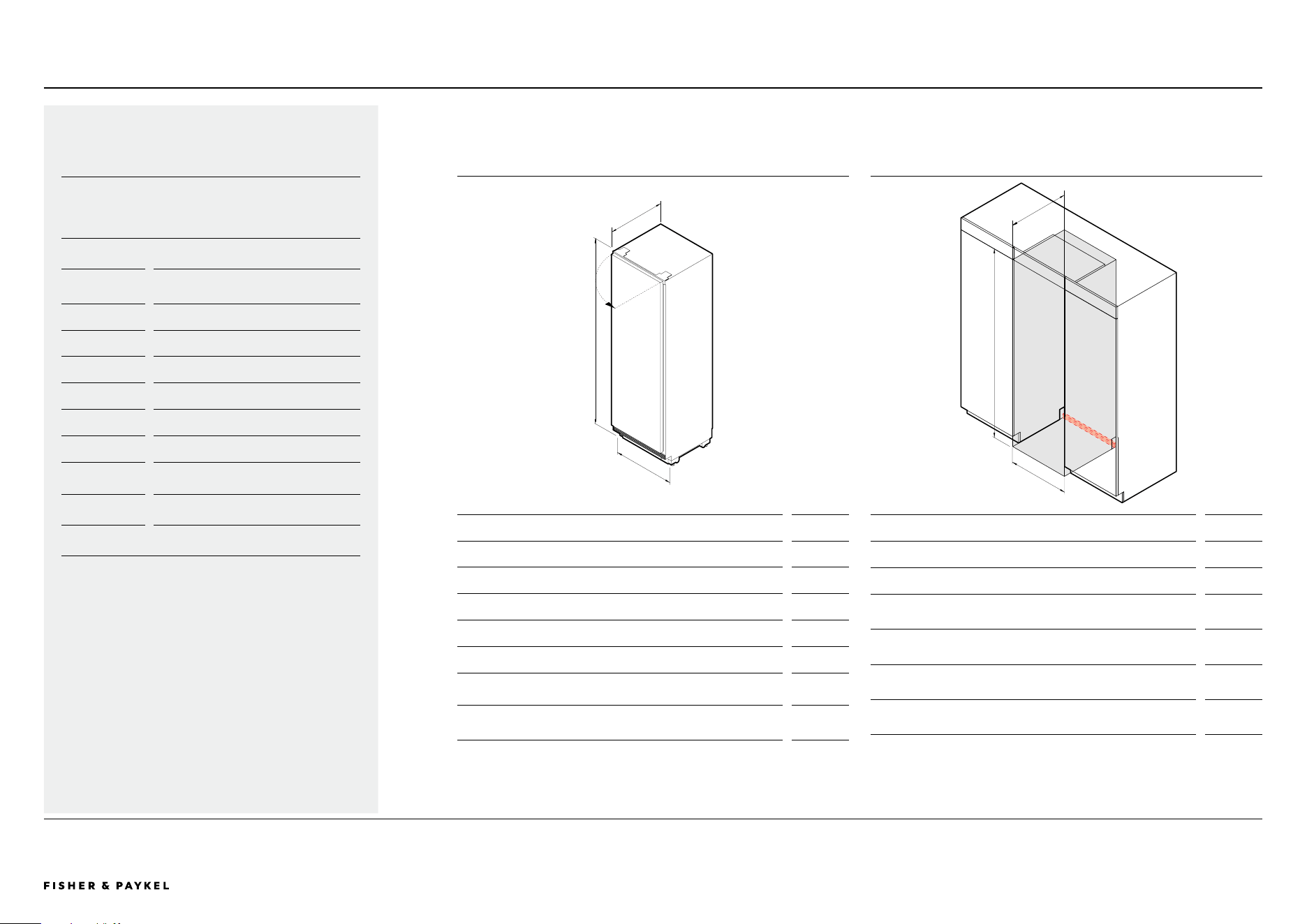
PRODUCT DIMENSIONS
mm
A Overall height 1880
B Overall width 592
C Overall depth* 579
D Overall depth with the door open* 1200
Height of toe kick panel 100
Height from floor to bottom of door panel
(custom panel)**
15 – 150
Depth of toe kick (excl. front door panel and
toe kick panel)
50 – 100
*Excluding door panel and handle.
**The grille becomes visible at heights over 100mm. Only applies to custom panels.
Note: Maximum custom door panel thickness of 19mm.
CAVITY DIMENSIONS: STANDARD INSTALLATION
mm
A Cavity height 1880
B Minimum cavity width 600
C Minimum overall depth of cavity (services located at
outside of cavity)
600
Minimum overall depth of cavity (services located in
cabinet above the cavity)
610
Minimum overall depth of cavity (services located at
rear of cavity)
650
Service area
H37mm x W600mm x D20mm
SPECIFICATION GUIDE | INTEGRATED REFRIGERATOR FREEZER, 1.88M HIGH
SPECIFICATIONS
Model No. RS6019BRU1
Product
Dimensions
H 1880mm W 592mm D 579mm
Electrical
Supply 230 V, 50 Hz
Service 10 A
Connection Flex cord with plug
Plumbing
Supply Water Filter
UK EU IE
SG HK
Braided hose, 7/16" x 24 UNS to 3/4"
BSP
NZ AU
Braided hose, 7 x 16-24 UNS to 1/2"
BSP
Pressure
min 275 kPa (40 psi)
max 827 kPa (120 psi)
A
B
C
A
B
C
RS6019BRU1
<< CONTENTS
The models shown in this Planning Guide may not be available in all markets and are subject to change at any time. Product specifications may vary from those shown. This Planning Guide should not be used as installation guidance for any
product. Further information is required to safely and correctly install the products featured here. Specific installation guidance will be available on our website fisherpaykel.com
© FISHER & PAYKEL LIMITED 2024 PAGE 1090002833C PLANNING GUIDE REFRIGERATION - VERSION C - OCTOBER 2024
PRODUCT DIMENSIONS
mm
A Overall height 1880
B Overall width 592
C Overall depth* 579
D Overall depth with the door open* 1200
Height of toe kick panel 100
Height from floor to bottom of door panel
(custom panel)**
15 – 150
Depth of toe kick (excl. front door panel and
toe kick panel)
50 – 100
*Excluding door panel and handle.
**The grille becomes visible at heights over 100mm. Only applies to custom panels.
Note: Maximum custom door panel thickness of 19mm.
CAVITY DIMENSIONS: STANDARD INSTALLATION
mm
A Cavity height 1880
B Minimum cavity width 600
C Minimum overall depth of cavity (services located at
outside of cavity)
600
Minimum overall depth of cavity (services located in
cabinet above the cavity)
610
Minimum overall depth of cavity (services located at
rear of cavity)
650
Service area
H37mm x W600mm x D20mm
SPECIFICATION GUIDE | INTEGRATED REFRIGERATOR AND FREEZER, 1.88M HIGH
A
B
C
A
B
C
SPECIFICATIONS
Model No.
RS6019S2R1, RS6019S3RH1,
RS6019F2L1, RS6019F3LJ1
Product
Dimensions
H 1880mm W 592mm D 579mm
Electrical
Supply 230 V, 50 Hz
Service 10 A
Connection Flex cord with plug
Plumbing
Supply Water Filter
UK EU IE
SG HK
Braided hose, 7/16" x 24 UNS to 3/4"
BSP
NZ AU
Braided hose, 7 x 16-24 UNS to 1/2"
BSP
Pressure
min 275 kPa (40 psi)
max 827 kPa (120 psi)
RS6019S2R1 | RS6019S3RH1 | RS6019F2L1 | RS6019F3LJ1
<< CONTENTS

© FISHER & PAYKEL LIMITED 2024 PAGE 1190002833C PLANNING GUIDE REFRIGERATION - VERSION C - OCTOBER 2024
DATA SHEETS
Data Sheets
IMPORTANT NOTE: Throughout this guide, dimensions may vary by ±2mm
(1/16''). Please read the Installation Guide for detailed information on
installing the product. For full installation instructions visit fisherpaykel.com
INDICATES PRODUCT DATUM -------------------------------------------
INDICATES CABINETRY CLEARANCES --------------------------------
© FISHER & PAYKEL LIMITED 2024 PAGE 1290002833C PLANNING GUIDE REFRIGERATION - VERSION C - OCTOBER 2024
R
Integrated Refrigerator Freezer
DATA SHEET | INTEGRATED REFRIGERATOR FREEZER
G
Q
B
A
H
J
K
E
F
N
P
D
O C
579mm592mm
1880mm
FLOOR
PLAN VIEW
DATUM: FRONT OF INNER DOOR
DATUM: FRONT OF INNER DOOR
HORIZONTAL GAP
CLEARANCE FROM SIDE
OF DOOR PANEL
4mm
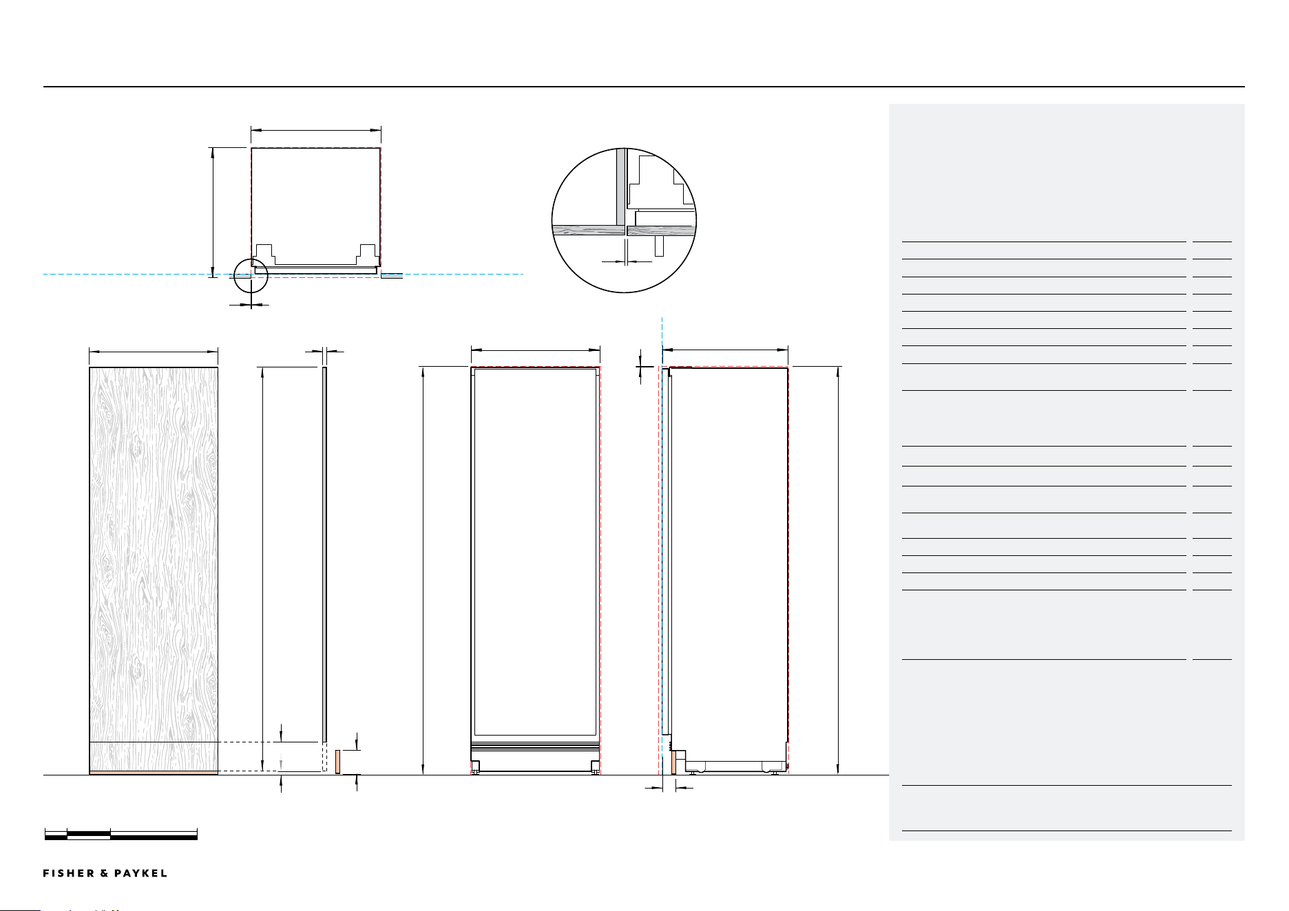
Model no:
Integrated Refrigerator Freezer - RS6019BRU1
Stainless Steel Panels - RD6019BR
Stainless Steel Toe Kick Panel - AKRS06010
Handle Kit - AHD5RDSF
Note: Left-hand hinge is a mirrored version of the image shown. Left-hand
hinge can be achieved using supplied parts. Please refer to Installation Guide
for details.
Product Dimensions mm
A Overall height of product 1880
B Overall width of product 592
C Overall depth of product (excl. front door panels) 579
D Minimum cabinetry clearance from top of stainless steel door
panel
3
E Height from top of top stainless steel door panel to floor 1877
F Height from top of bottom stainless steel door panel to floor 873
G Minimum cabinetry clearance from side of stainless steel door
panel
4
H Height of top stainless steel door panel 1001
I Gap between stainless steel door panels
3
J Height of bottom stainless steel door panel 771
K Height of visual toe kick 102
L Width of stainless steel door panels 592
M Height of stainless steel toe kick panel 100
N Depth of toe kick (excl. front door panel and toe kick panel)
min 50
max 100
O Thickness of stainless steel door panels 18
Cavity Dimensions mm
P Overall height of cavity 1880
Q Overall width of cavity 600
R Minimum overall depth of cavity (including front panel):
When services are located outside of cavity (shallow) 600
When services are located in the cabinet above the cavity 610
When services are located at rear of cavity (deep) 650
Note: Product shown installed on the floor. Slide into cabinetry position. Alternatively can be
installed on a plinth. Adjust your cavity height accordingly
G
I
M
L
RS6019BRU1
FRONT VIEW PROFILE VIEW
Millimetre
0 100 200 400
<< CONTENTS
IMPORTANT NOTE: Throughout this guide, dimensions may vary by ±2mm
(1/16''). Please read the Installation Guide for detailed information on
installing the product. For full installation instructions visit fisherpaykel.com
INDICATES PRODUCT DATUM -------------------------------------------
INDICATES CABINETRY CLEARANCES --------------------------------
© FISHER & PAYKEL LIMITED 2024 PAGE 1390002833C PLANNING GUIDE REFRIGERATION - VERSION C - OCTOBER 2024
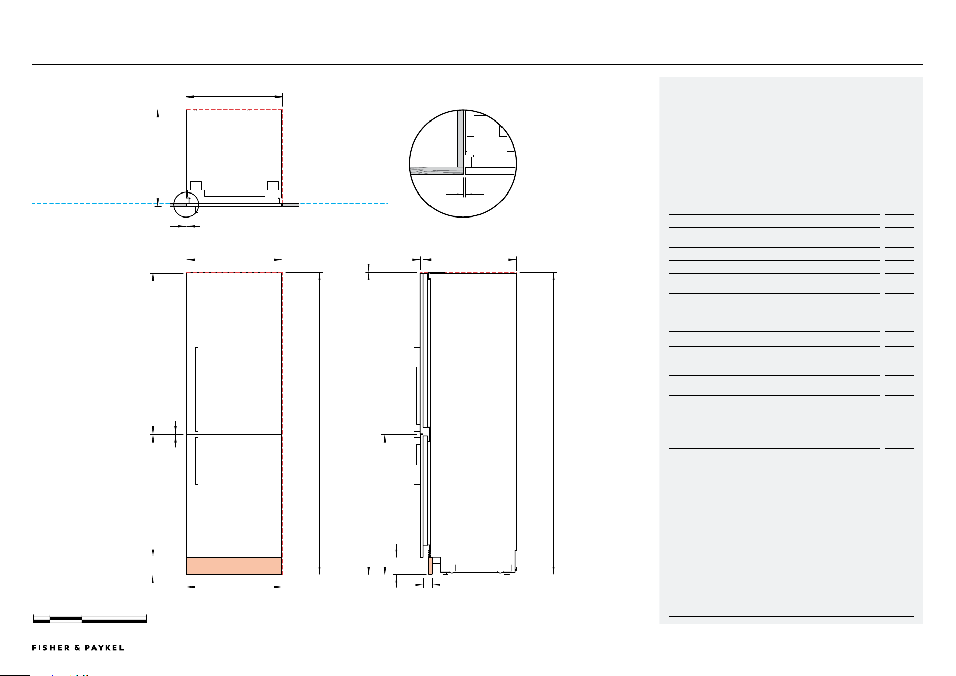
Integrated Refrigerator Freezer, Custom Panel
DATA SHEET | INTEGRATED REFRIGERATOR FREEZER, CUSTOM PANEL RS6019BRU1
Millimetre
0 100 200 400
P
D
O
N
FLOOR
PLAN VIEW
DATUM: FRONT OF INNER DOOR
DATUM: FRONT OF INNER DOOR
HORIZONTAL GAP
CLEARANCE FROM SIDE
OF DOOR PANEL
4mm
Model no:
Integrated Refrigerator Freezer - RS6019BRU1
Custom Panel
Note: Left-hand hinge is a mirrored version of the image shown. Left-hand
hinge can be achieved using supplied parts. Please refer to Installation Guide
for details.
Product Dimensions mm
A Overall height of product 1880
B Overall width of product 592
C Overall depth of product 579
D Minimum cabinetry clearance from side of door panels*
4
E Minimum cabinetry clearance from top of door panel*
3
F Thickness of custom door panel*
16 - 19
G Height of top custom door panel 1001
H Gap between door panels 3
I Height of bottom custom door panel 721 - 856
J Width of custom door panels
Single install
Dual install
Triple install
592
594
594.5
K Height of visual toe kick** 15 - 150
L Height of custom toe kick panel* 100
M Depth of custom toe kick (excl. front door panel and toe kick
panel)*
min 50
max 100
*Custom door panels and toe kick panel to be manufactured and fitted by cabinet maker.
**The grille becomes visible at heights over 100mm.
Cavity Dimensions mm
N Overall height of cavity 1880
O Overall width of cavity 600
P Minimum overall depth of cavity (including front panel):
When services are located outside of cavity (shallow) 600
When services are located in the cabinet above the cavity 610
When services are located at rear of cavity (deep) 650
Note: Product shown installed on the floor. Slide into cabinetry position. Alternatively can be
installed on a plinth. Adjust your cavity height accordingly.
D
M
L
B C
579mm592mm
FRONT VIEW PROFILE VIEW
K
F
G
A
1880mm
I
H
CUSTOM PANELS
J
E
<< CONTENTS
IMPORTANT NOTE: Throughout this guide, dimensions may vary by ±2mm
(1/16''). Please read the Installation Guide for detailed information on
installing the product. For full installation instructions visit fisherpaykel.com
INDICATES PRODUCT DATUM -------------------------------------------
INDICATES CABINETRY CLEARANCES --------------------------------
© FISHER & PAYKEL LIMITED 2024 PAGE 1490002833C PLANNING GUIDE REFRIGERATION - VERSION C - OCTOBER 2024
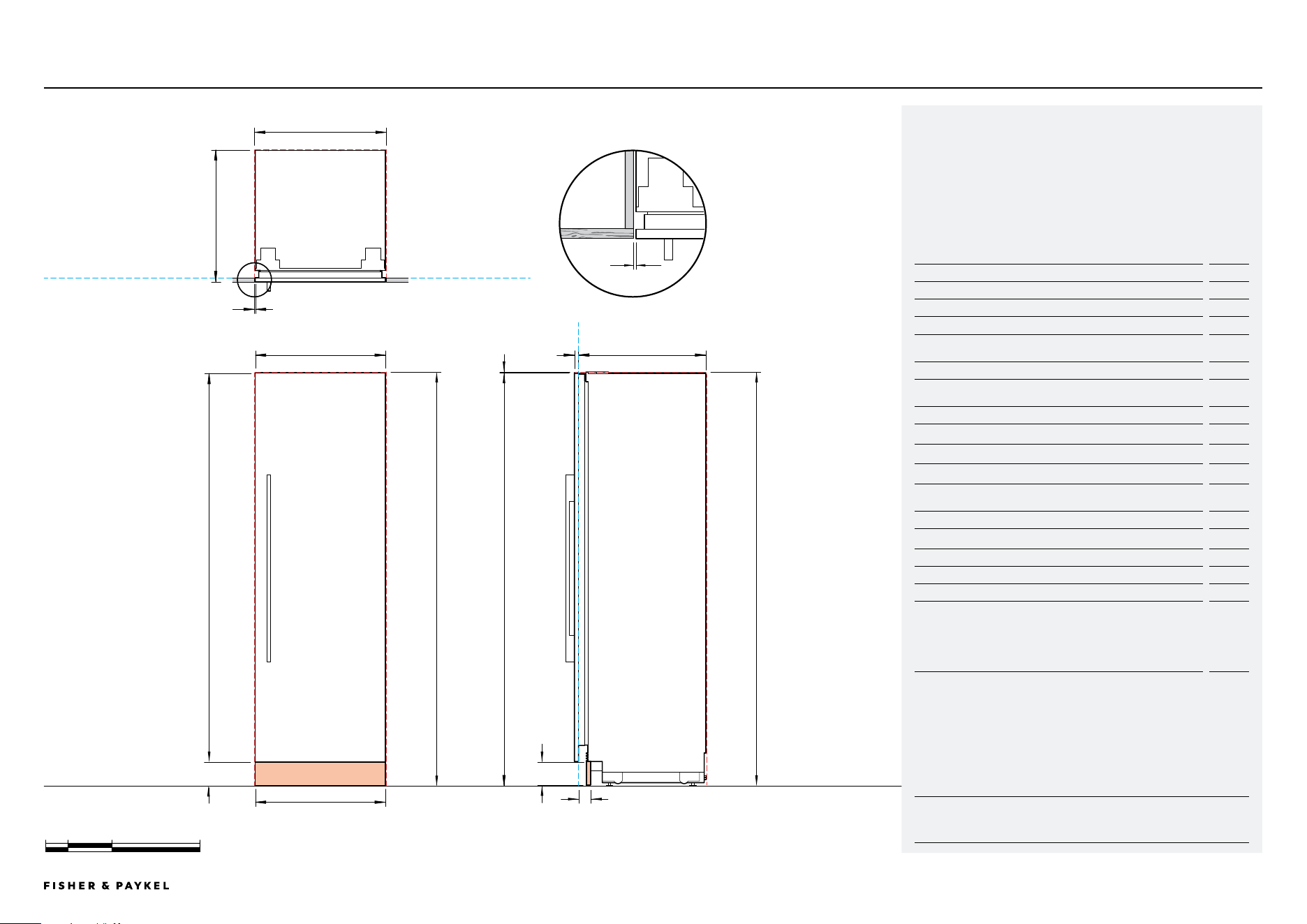
Integrated Refrigerator and Freezer
DATA SHEET | INTEGRATED REFRIGERATOR AND FREEZER
Model no:
Integrated Refrigerator - RS6019S2R1, RS6019S3RH1
Integrated Freezer - RS6019F2L1, RS6019F3LJ1
Stainless Steel Panels - RD6019
Handle Kit - AHD5RDSF
Stainless Steel Toe Kick Panel - AKRS06010
Note: Left-hand hinge is a mirrored version of the image shown. Left-hand
hinge can be achieved using supplied parts. Please refer to Installation Guide
for details.
Product Dimensions mm
A Overall height of product 1880
B Overall width of product 592
C Overall depth of product (excl. front door panels) 579
D Minimum cabinetry clearance from top of stainless steel door
panel
3
E Height from top of stainless steel door panel to floor 1877
F Minimum cabinetry clearance from side of stainless steel door
panel
4
G Height of stainless steel door panel 1775
H Height of visual toe kick 102
I Width of stainless steel door panel 592
J Height of stainless steel toe kick panel 100
K Depth of toe kick (excl. front door panel and toe kick panel)
min 50
max 100
L Thickness of stainless steel door panel 18
Cavity Dimensions mm
M Overall height of cavity 1880
N Overall width of cavity 600
O Minimum overall depth of cavity (including front panel):
When services are located outside of cavity (shallow) 600
When services are located in the cabinet above the cavity 610
When services are located at rear of cavity (deep) 650
Note: Product shown installed on the floor. Slide into cabinetry position. Alternatively can be
installed on a plinth. Adjust your cavity height accordingly.
O
F
N
G
H
E
M
D
L
FLOOR
PLAN VIEW
DATUM: FRONT OF INNER DOOR
DATUM: FRONT OF INNER DOOR
HORIZONTAL GAP
CLEARANCE FROM SIDE
OF DOOR PANEL
4mm
F
K
J
B
A
C
579mm592mm
1880mm
I
RS6019S2R1 | RS6019S3RH1 | RS6019F2L1 | RS6019F3LJ1
FRONT VIEW PROFILE VIEW
Millimetre
0 100 200 400
<< CONTENTS
IMPORTANT NOTE: Throughout this guide, dimensions may vary by ±2mm
(1/16''). Please read the Installation Guide for detailed information on
installing the product. For full installation instructions visit fisherpaykel.com
INDICATES PRODUCT DATUM -------------------------------------------
INDICATES CABINETRY CLEARANCES --------------------------------
© FISHER & PAYKEL LIMITED 2024 PAGE 1590002833C PLANNING GUIDE REFRIGERATION - VERSION C - OCTOBER 2024
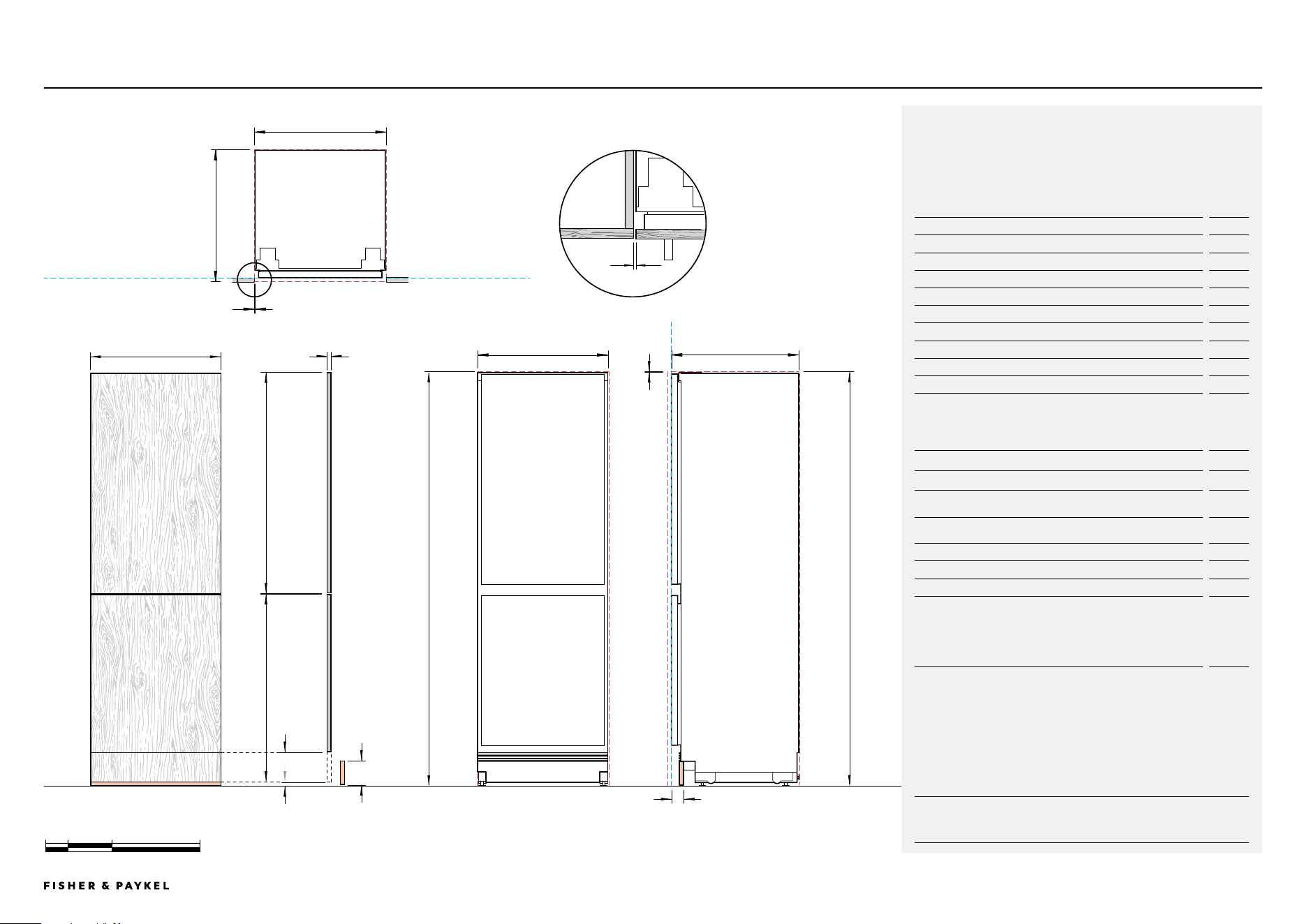
Integrated Refrigerator and Freezer, Custom Panel
DATA SHEET | INTEGRATED REFRIGERATOR AND FREEZER, CUSTOM PANEL RS6019S2R1 | RS6019S3RH1 | RS6019F2L1 | RS6019F3LJ1
Model no:
Integrated Refrigerator - RS6019S2R1, RS6019S3RH1
Integrated Freezer - RS6019F2L1, RS6019F3LJ1
Custom Panel
Note:Left-hand hinge is a mirrored version of the image shown. Left-hand
hinge can be achieved using supplied parts. Please refer to Installation Guide
for details.
Product Dimensions mm
A Overall height of product 1880
B Overall width of product 592
C Overall depth of product 579
D Minimum cabinetry clearance from side of door panel*
4
E Minimum cabinetry clearance from top of door panel*
3
F Thickness of custom door panel*
16 - 19
G Height of custom door panel
1725 -
1860
H Width of custom door panel
Single install
Dual install
Triple install
592
594
594.5
I Height of visual toe kick** 15 - 150
J Height of custom toe kick panel* 100
K Depth of custom toe kick (excl. front door panel and toe kick
panel)*
min 50
max 100
*Custom door panel and toe kick panel to be manufactured and fitted by cabinet maker.
**The grille becomes visible at heights over 3 15/16" (100mm).
Cavity Dimensions mm
L Overall height of cavity 1880
M Overall width of cavity 600
N Minimum overall depth of cavity (including front panel):
When services are located outside of cavity (shallow) 600
When services are located in the cabinet above the cavity 610
When services are located at rear of cavity (deep) 650
Note: Product shown installed on the floor. Slide into cabinetry position. Alternatively can be
installed on a plinth. Adjust your cavity height accordingly.
FLOOR
PLAN VIEW
DATUM: FRONT OF INNER DOOR
HORIZONTAL GAP
CLEARANCE FROM SIDE
OF DOOR PANEL
4mm
N
D
M
D
L
K
J
B C
579mm592mm
FRONT VIEW PROFILE VIEW
I
F
A
1880mm
G
CUSTOM PANELS
H
DATUM: FRONT OF INNER DOOR
Millimetre
0 100 200 400
E
<< CONTENTS

© FISHER & PAYKEL LIMITED 2024 PAGE 1690002833C PLANNING GUIDE REFRIGERATION - VERSION C - OCTOBER 2024
CUSTOM PANELS
Custom Panels
The models shown in this Planning Guide may not be available in all markets and are subject to change at any time. Product specifications may vary from those shown. This Planning Guide should not be used as installation guidance for any
product. Further information is required to safely and correctly install the products featured here. Specific installation guidance will be available on our website fisherpaykel.com
© FISHER & PAYKEL LIMITED 2024 PAGE 1790002833C PLANNING GUIDE REFRIGERATION - VERSION C - OCTOBER 2024
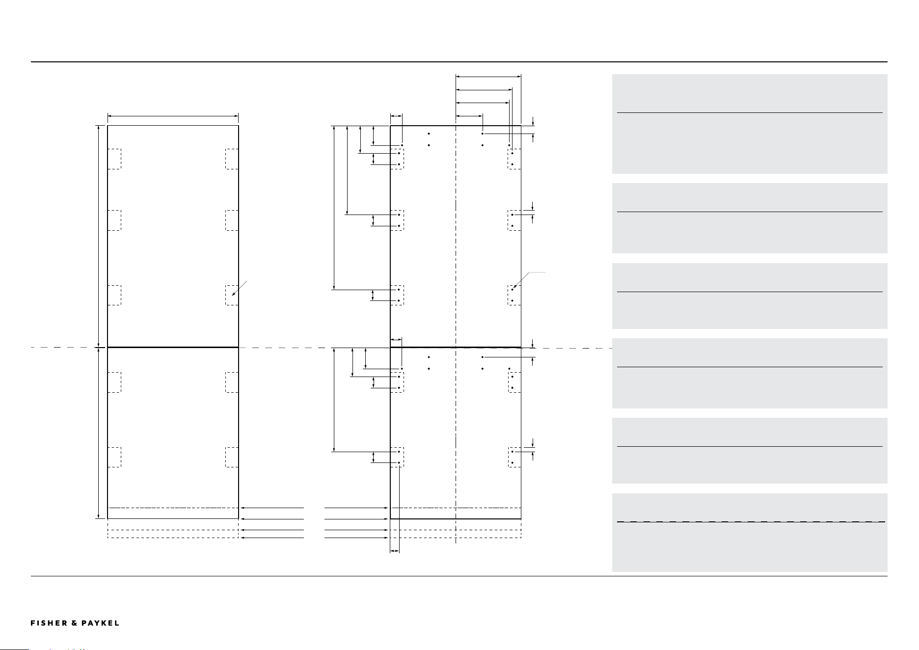
Integrated Refrigerator Freezer
CUSTOM PANELS | INTEGRATED REFRIGERATOR FREEZER, CUSTOM DOOR PREPARATION
1001mm
771mm
3mm
TOP PANEL
BOTTOM PANEL
Ø2.5mm
Pilot holes only
Do not
penetrate front
surface.
Do not place
handle holes in
these locations.
FRONT VIEW REAR VIEW
1
3
4
2
40mm
592mm
740mm
403mm
50mm
88mm
125mm
50mm50mm50mm
54mm
121mm
242mm
256mm
296mm
36mm20mm
50mm
42mm20mm
469mm
130mm
94mm
54mm
BRACKET HOLE LOCATIONS
Ø 2.5mm pilot holes, all holes 15mm deep. Do not penetrate front face.
HANDLE HOLE LOCATIONS
All Fisher & Paykel handle holes Ø 6mm.
Do not place handle holes in bracket hole locations.
VISUAL TOE KICK HEIGHT FROM FLOOR TO BOTTOM OF
DOOR PANEL
1 Visual toe kick height 150mm custom door panel 50mm shorter
2 Visual toe kick height 100mm
3 Visual toe kick height 50mm custom door panel 50mm longer
4 Visual toe kick height 15mm custom door panel 85mm longer
CUSTOM PANEL WEIGHT
Custom top panel: Max 9.5kg
Custom bottom panel: Max 9kg
Note: Door weights includes weight of handle.
DWG & DXF FILES AND TEMPLATE
Dwg and Dxf files of the panel preparation can be downloaded from Trade Resources
www.fisherpaykel.com.
A template for marking and drilling the holes is provided with the product.
GAP BETWEEN CUSTOM DOOR PANELS
Allow 3 mm gap between the top of the custom door panel and the bottom custom
door panel.
RS6019BRU1
<< CONTENTS
The models shown in this Planning Guide may not be available in all markets and are subject to change at any time. Product specifications may vary from those shown. This Planning Guide should not be used as installation guidance for any
product. Further information is required to safely and correctly install the products featured here. Specific installation guidance will be available on our website fisherpaykel.com
© FISHER & PAYKEL LIMITED 2024 PAGE 1890002833C PLANNING GUIDE REFRIGERATION - VERSION C - OCTOBER 2024
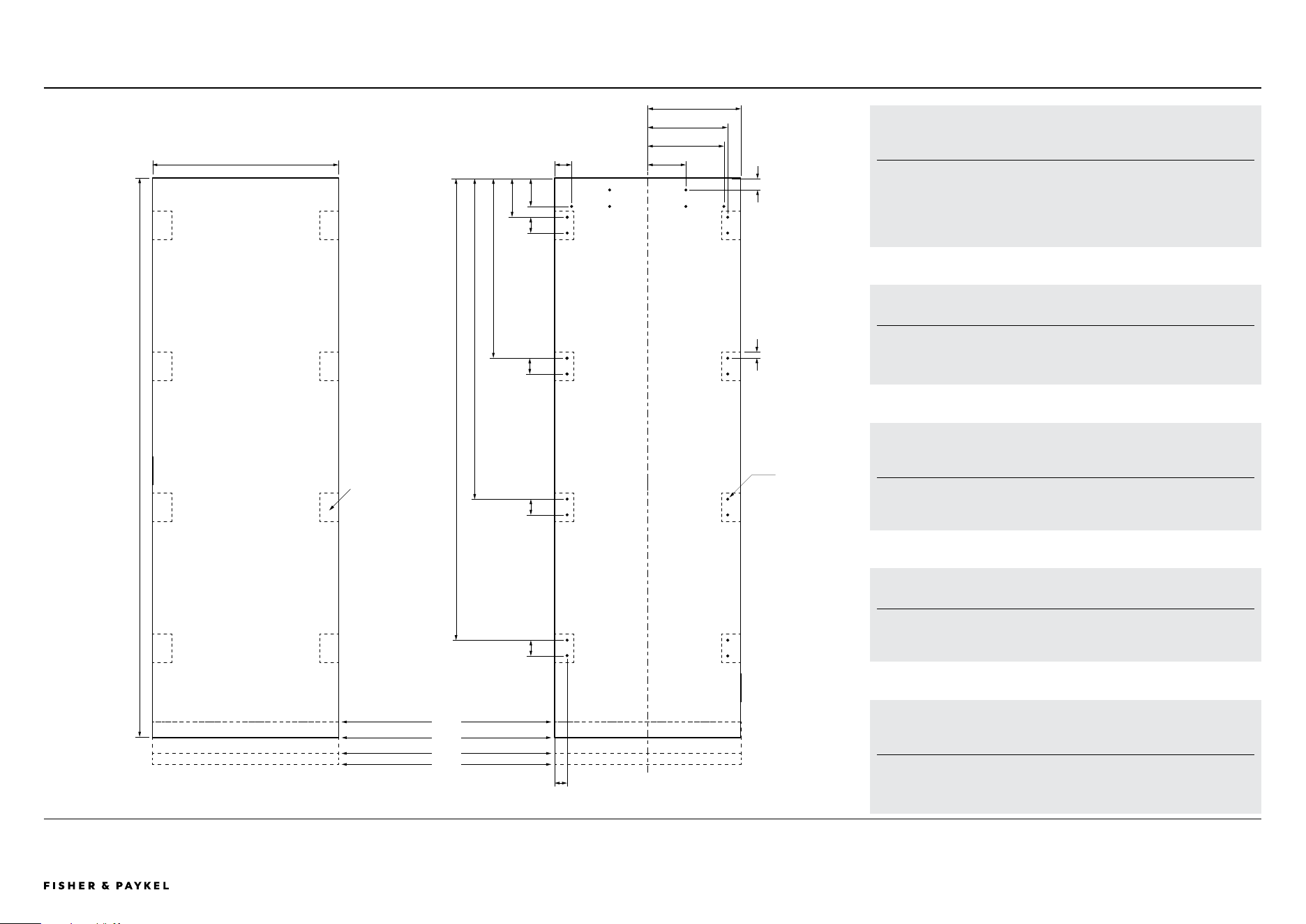
Integrated Refrigerator and Freezer
CUSTOM PANELS | INTEGRATED REFRIGERATOR AND FREEZER, CUSTOM DOOR PREPARATION
1777mm
1473mm
1023mm
574mm
50mm
88mm
125mm
50mm50mm50mm
54mm
40mm
592mm 121mm
242mm
256mm
296mm
36mm20mm
Ø2.5mm
Pilot holes only
Do not
penetrate front
surface.
Do not place
handle holes in
these locations.
FRONT VIEW REAR VIEW
1
3
4
2
FRONT OF CUSTOM DOOR PANEL
HANDLE HOLE LOCATIONS
All Fisher & Paykel handle holes Ø6mm.
Do not place handle holes in bracket hole locations.
VISUAL TOE KICK HEIGHT FROM FLOOR TO BOTTOM OF
DOOR PANEL
1 Visual toe kick height 150mm custom door panel 50mm shorter
2 Visual toe kick height 100mm
3 Visual toe kick height 50mm custom door panel 50mm longer
4 Visual toe kick height 15mm custom door panel 85mm longer
CUSTOM PANEL WEIGHT
Custom single panel: Max 19kg
Note: Door weights includes weight of handle.
DWG & DXF FILES AND TEMPLATE
Dwg and Dxf files of the panel preparation can be downloaded from Trade Resources
www.fisherpaykel.com.
A template for marking and drilling the holes is provided with the product.
BACK OF CUSTOM DOOR PANEL
BRACKET HOLE LOCATIONS
Ø2.5mm pilot holes, all holes 15mm deep. Do not penetrate front face.
RS6019S2R1 | RS6019S3RH1 |
RS6019F2L1 | RS6019F3LJ1
<< CONTENTS

© FISHER & PAYKEL LIMITED 2024 PAGE 1990002833C PLANNING GUIDE REFRIGERATION - VERSION C - OCTOBER 2024
PLANNING CONSIDERATIONS
Planning Considerations
The models shown in this Planning Guide may not be available in all markets and are subject to change at any time. Product specifications may vary from those shown. This Planning Guide should not be used as installation guidance for any
product. Further information is required to safely and correctly install the products featured here. Specific installation guidance will be available on our website fisherpaykel.com
© FISHER & PAYKEL LIMITED 2024 PAGE 2090002833C PLANNING GUIDE REFRIGERATION - VERSION C - OCTOBER 2024
PLANNING CONSIDERATIONS | PRODUCT DIMENSIONS
Product Dimensions
A
B
C
D
E
F
RS6019S2R1, RS6019S3RH1, RS6019F2L1 or
RS6019F3LJ1
C
A
B
D
F
E
Electrical and
plumbing
Alternative area above cavity
for electrical and plumbing
connection
ADJACENT CABINETRY
PLAN VIEW
CABINETRY RETURN
1
Finished return on side and top = Min 100mm
PRODUCT DIMENSIONS DOUBLE DOOR SINGLE DOOR
Dimensions mm mm
A Overall height of product 1880 1880
B Overall width of product 592 592
C Overall depth of product (not including door panel) 579 579
CAVITY DIMENSIONS
D Overall height of cavity 1880 1880
E Overall width of cavity 600 600
F Minimum overall depth of cavity
(services located at outside of cavity)
600 600
Minimum overall depth of cavity
(services located in cabinet above the cavity)
610 610
Minimum overall depth of cavity
(services located at rear of cavity)
650 650
RS6019BRU1
1
RS6019BRU1 | RS6019S2R1 | RS6019S3RH1 | RS6019F2L1 | RS6019F3LJ1
<< CONTENTS
The models shown in this Planning Guide may not be available in all markets and are subject to change at any time. Product specifications may vary from those shown. This Planning Guide should not be used as installation guidance for any
product. Further information is required to safely and correctly install the products featured here. Specific installation guidance will be available on our website fisherpaykel.com
© FISHER & PAYKEL LIMITED 2024 PAGE 2190002833C PLANNING GUIDE REFRIGERATION - VERSION C - OCTOBER 2024
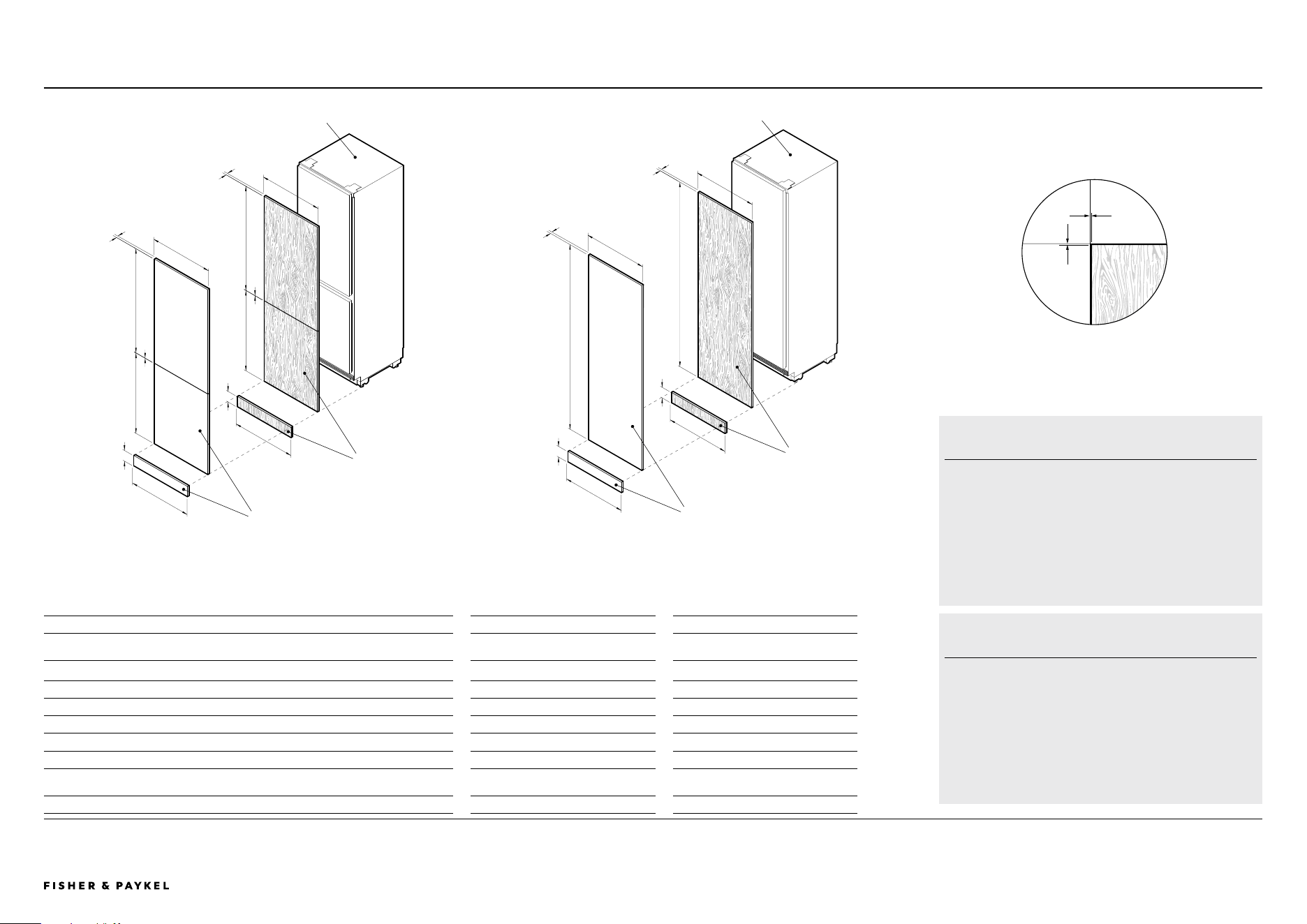
PANEL AND TOE KICK DIMENSIONS CUSTOM PANEL STAINLESS STEEL PANEL
Dimensions mm mm
A Door panel height - single door
min 1725
max 1860
1775
B Top door panel height - double door 1001 1001
C Gap between door panels 3 3
D Bottom door panel height - double door 721 - 856 771
E Door panel width 592 592
F Door panel thickness 16 - 19 18
G Toe kick height 100 100
Visual toe kick height
min 15
max 150
102
H Toe kick width 597 596
PLANNING CONSIDERATIONS | PANEL AND TOE KICK DIMENSIONS
A
E
B
E
E
RS6019S2R1, RS6019S3RH1,
RS6019F2L1 or RS6019F3LJ1
F
G
H
A
E
F
H
G
ADJACENT CABINETRY
C
D
B
C
D
F
F
G
G
H
H
RS6019BRU1
STAINLESS STEEL
Single door panels: RD6019
Double door panels: RD6019BL or RD6019BR
Single install toe kick: AKRS06010
Panel and Toe Kick Dimensions
1
Stainless Steel
Custom
Stainless Steel
Custom
RS6019BRU1 | RS6019S2R1 | RS6019S3RH1 | RS6019F2L1 | RS6019F3LJ1
ADJACENT CABINETRY (SINGLE INSTALL)
1
Vertical gap clearance from side of door panel to
adjacent cabinetry. Min (4mm)
2
Horizontal gaps between door and neighbouring
cabinetry. Min (3mm)
FRONT VIEW
<< CONTENTS
The models shown in this Planning Guide may not be available in all markets and are subject to change at any time. Product specifications may vary from those shown. This Planning Guide should not be used as installation guidance for any
product. Further information is required to safely and correctly install the products featured here. Specific installation guidance will be available on our website fisherpaykel.com
© FISHER & PAYKEL LIMITED 2024 PAGE 2290002833C PLANNING GUIDE REFRIGERATION - VERSION C - OCTOBER 2024
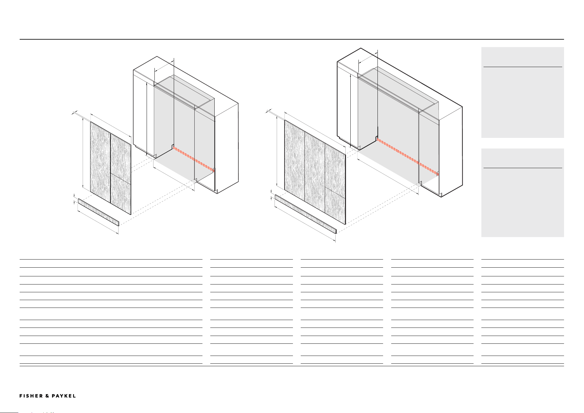
Dual and Triple
DUAL AND TRIPLE
CAVITY DIMENSIONS CUSTOM - DUAL STAINLESS STEEL - DUAL CUSTOM - TRIPLE STAINLESS STEEL - TRIPLE
Dimensions mm mm mm mm
A Overall height of cavity 1880 1880 1880 1880
B Overall width of cavity 1200 1200 1880 1880
C Minimum overall depth of cavity (services located at outside of cavity) 600 600 600 600
Minimum overall depth of cavity (services located in cabinet above the cavity) 610 610 610 610
Minimum overall depth of cavity (services located at rear of cavity) 650 650 650 650
D Door panel height
min 1725
max 1860
1775
min 1725
max 1860
1775
E Overall door panel widths (including vertical gaps between doors) 1192 1192 1791.5 1788
F Door panel thickness 16 - 19 18 16 - 19 18
G Toe kick panel height 100 100 100 100
Visual toe kick height
min 15
max 150
102
min 15
max 150
102
H Overall toe kick width 1196 1196 1796 1796
PLANNING CONSIDERATIONS | PRODUCT DIMENSIONS
A
A
B
B
C
C
D
D
E
E
F
F
H
H
G
G
JOINER KIT
Joiner kit: AJRS19LR
Dual installation: 1x joiner kit
required
Triple installation: 2x joiner
kits required
STAINLESS STEEL
Single door panels: RD6019
Double door panels: RD6019BL
or RD6019BR
Dual toe kick: AKRS12010
Triple toe kick: AKRS18010
<< CONTENTS
The models shown in this Planning Guide may not be available in all markets and are subject to change at any time. Product specifications may vary from those shown. This Planning Guide should not be used as installation guidance for any
product. Further information is required to safely and correctly install the products featured here. Specific installation guidance will be available on our website fisherpaykel.com
© FISHER & PAYKEL LIMITED 2024 PAGE 2390002833C PLANNING GUIDE REFRIGERATION - VERSION C - OCTOBER 2024
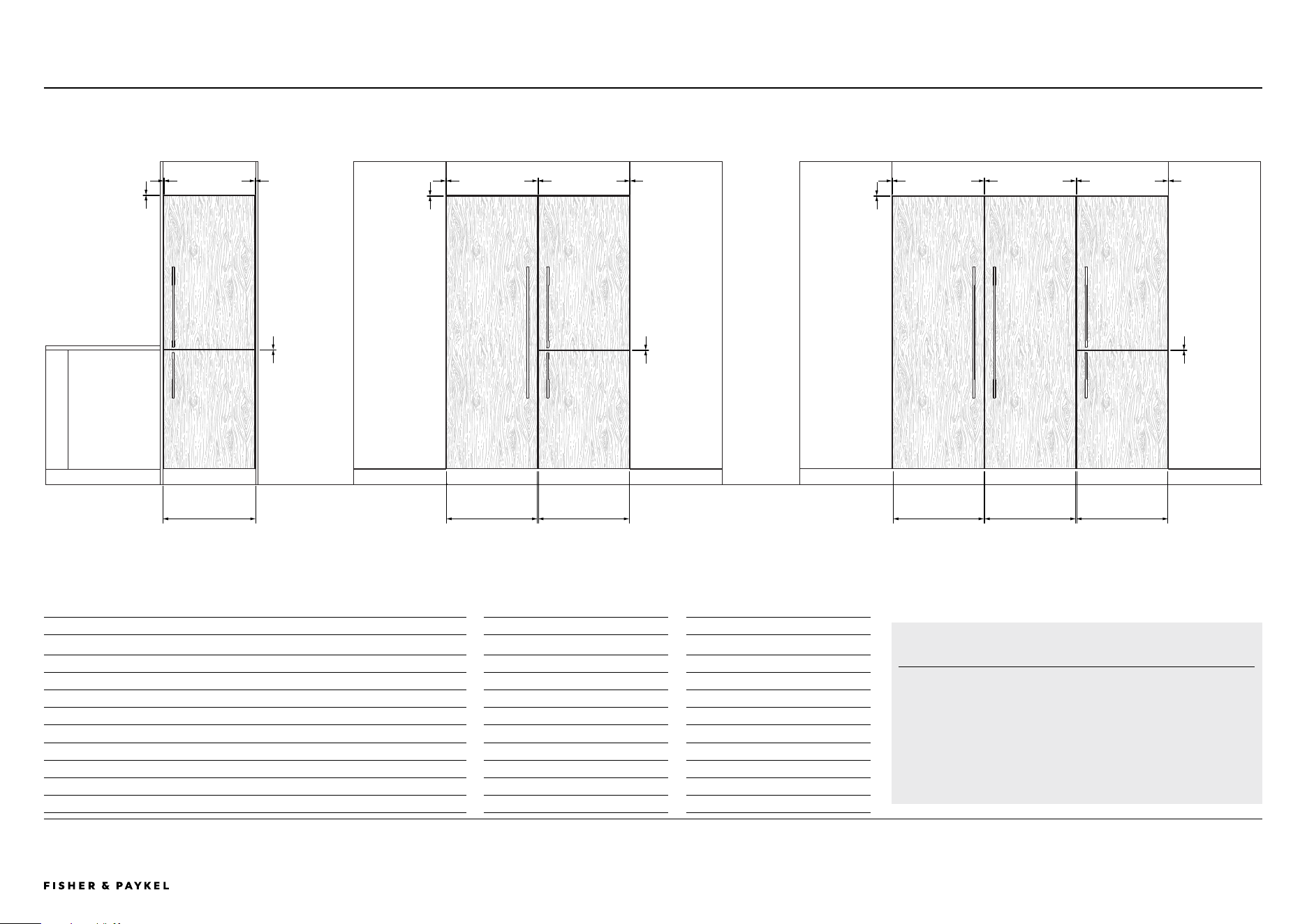
Gap Clearances
PLANNING CONSIDERATIONS | GAP CLEARANCES
CLEARANCES CUSTOM PANEL STAINLESS STEEL PANEL
Dimensions mm mm
A Horizontal gaps between doors 3 3
B Horizontal gaps between door and neighbouring cabinetry 3 3
C Vertical gaps between doors
Single install 4 4
Dual install 4 5
Triple install 4 6
D Door widths
Single install 592 592
Dual install 594 592
Triple install 594.5 592
A A A
B B
CC CC C CCC
B
SINGLE INSTALL DUAL INSTALL TRIPLE INSTALL
D D D
STAINLESS STEEL PANELS
Integrated Refrigerator Freezer:
Left RD6019BL and right RD6019BR
Integrated Refrigerator and Freezer:
RD6019
C
D D D
RS6019BRU1 | RS6019S2R1 | RS6019S3RH1 | RS6019F2L1 | RS6019F3LJ1
<< CONTENTS
The models shown in this Planning Guide may not be available in all markets and are subject to change at any time. Product specifications may vary from those shown. This Planning Guide should not be used as installation guidance for any
product. Further information is required to safely and correctly install the products featured here. Specific installation guidance will be available on our website fisherpaykel.com
© FISHER & PAYKEL LIMITED 2024 PAGE 2490002833C PLANNING GUIDE REFRIGERATION - VERSION C - OCTOBER 2024
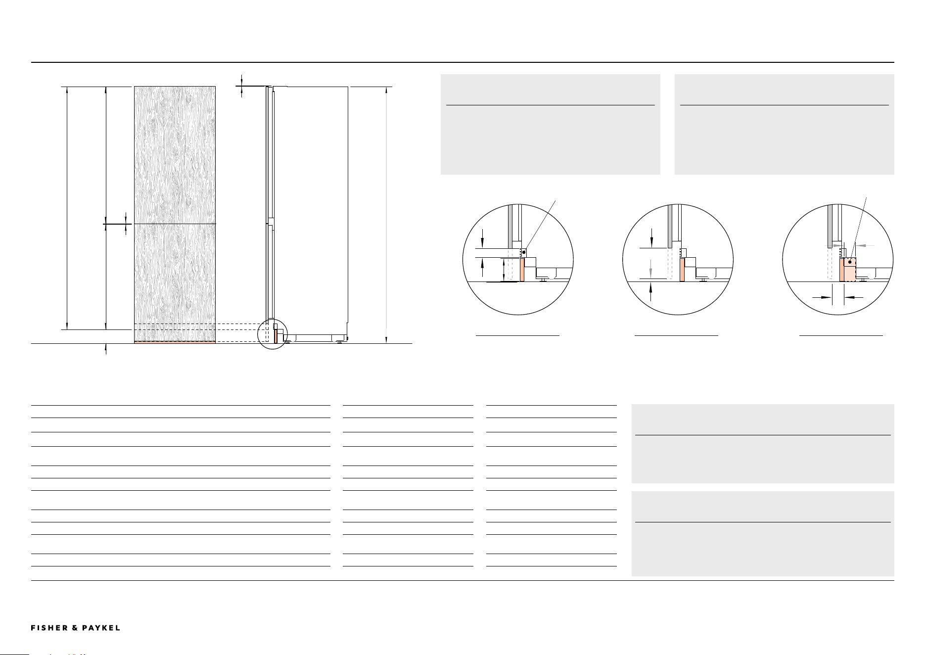
Toe Kick Detail
PLANNING CONSIDERATIONS | TOE KICK DETAIL
C
D
F
FRONT VIEW PROFILE VIEW
TOE KICK AND DOOR PANELS CUSTOM PANEL STAINLESS STEEL PANEL
Dimensions mm mm
A Overall product height 1880 1880
B Minimum cabinetry clearance from top of door panel 3 3
C Door panel height - single door
min 1725
max 1860
1775
D Top door panel height - double door 1001 1001
E Gap between door panels - double door 3 3
F Bottom door panel height - double door
min 721
max 856
771
G Grille height 50 50
H Toe kick panel height 100 100
I Visual toe kick height
min 15
max 150
102
J Depth of toe kick (excl. front door panel and toe kick panel) 50 - 100 50 - 100
Custom door panels and toe kick panel to be manufactured and fitted by cabinet maker.
G
H
I
E
GRILLE AND TOE KICK
PROFILE VIEW
CUSTOM DOOR PANEL
PROFILE VIEW
TOE KICK DEPTH
PROFILE VIEW
CUSTOM DOOR PANEL
Custom door panel can be longer or shorter to achieve
a smaller or bigger visual toe kick.
Head to 'Custom Panels' section of this planning guide
to find out more about custom panel heights.
STAINLESS STEEL DOOR PANEL
Grille will be hidden by the stainless steel front panel.
Toe kick panels are 100mm high.
Grille
1775mm
771mm
1001mm
FLOOR
1880mm
A
B
3mm
3mm
I
102mm
RS6019BRU1 | RS6019S2R1 | RS6019S3RH1 | RS6019F2L1 | RS6019F3LJ1
GRILLE - CUSTOM TOE KICK
The grille becomes visible if visual toe kick is higher than 100mm
high.
J
TOE KICK DEPTH
The toe kick mounting bracket extends out to 50mm. To ensure
proper alignment with the front of the grille, use a toe kick panel
that is minimum of 18mm thick.
Toe kick mounting
bracket
<< CONTENTS
The models shown in this Planning Guide may not be available in all markets and are subject to change at any time. Product specifications may vary from those shown. This Planning Guide should not be used as installation guidance for any
product. Further information is required to safely and correctly install the products featured here. Specific installation guidance will be available on our website fisherpaykel.com
© FISHER & PAYKEL LIMITED 2024 PAGE 2590002833C PLANNING GUIDE REFRIGERATION - VERSION C - OCTOBER 2024
PLANNING GUIDE | HINGE ARTICULATION
WEIGHT LIMIT
Custom single panel: Max 19kg
Custom top panel: Max 9.5kg
Custom bottom panel: Max 9kg
Note: Door weights includes weight of handle.
DOOR CLOSED
DOOR FULLY OPEN 115°
DOOR
90° OPEN
DOOR
45° OPEN
DOOR
22.5° OPEN
TOP VIEW
FRONT OF CABINETRY OR APPLIANCE
a
a
b
R2mm
Adjacent cabinetry
front panel requires
same radius
1 SQUARE = 10mm
b
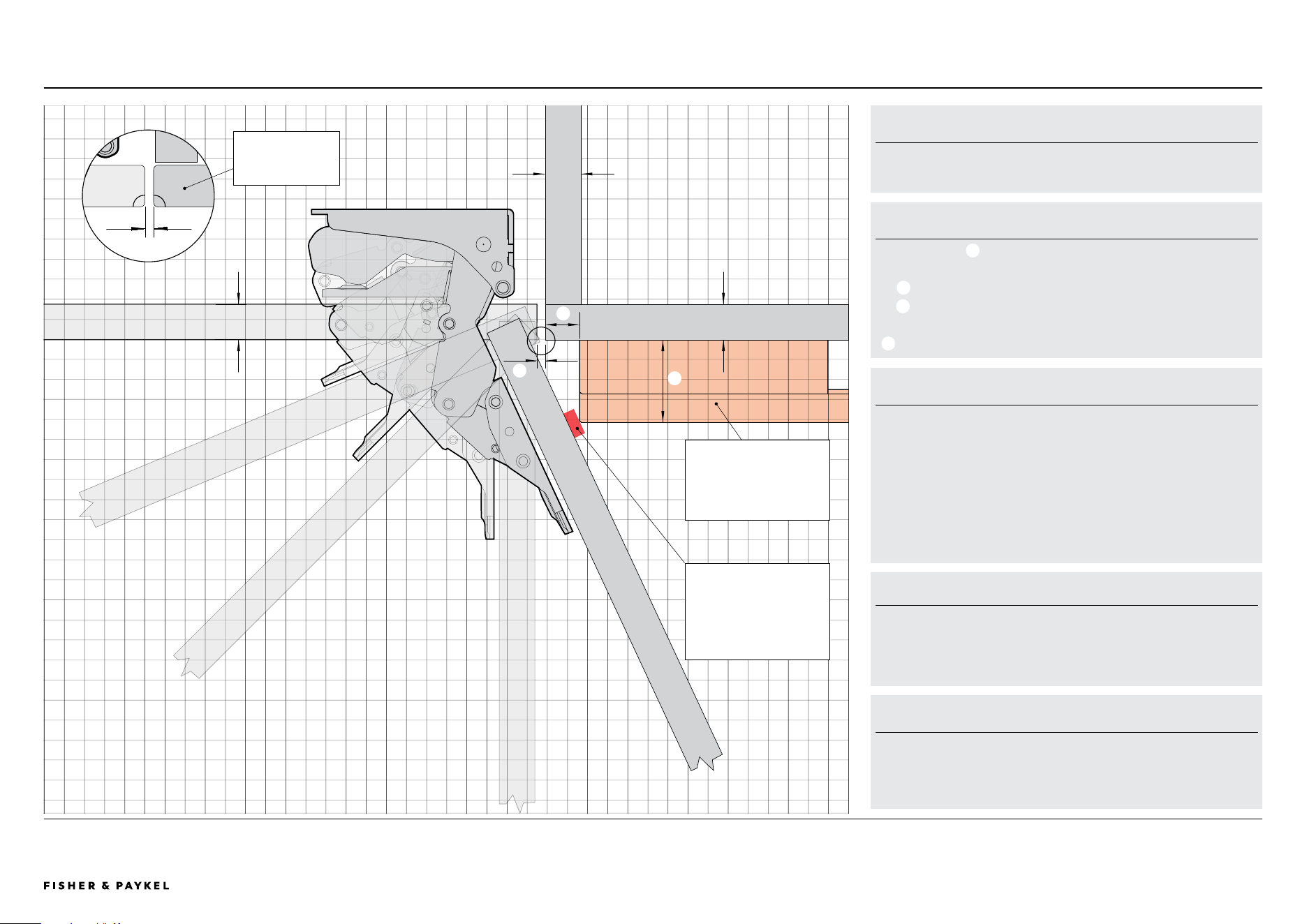
Hinge Articulation
DOOR HINGE - HETTICH K08
Left-hand hinge models are a mirror of
version shown.
CUSTOM FRONT PANEL
a
Front panel thickness: 16mm-19mm
Drawing shown with 18mm panels.
b
Gap between custom panel and adjacent cabinetry: Min 4mm
c
Minimum Fisher & Paykel minimal oven handle clearance: Min
16.5mm
d
Minimum depth of Fisher & Paykel minimal oven handle: Min 42mm
RADIUS REQUIREMENTS
Gap: Minimum 4mm
Panel thickness 16mm-19mm: Requires minimum R2mm
Minimum radius prevents clashes with adjacent cabinetry. Panels
thicker than 20mm need a larger gap and radius, which might expose
internal components.
TECHNICAL SUPPORT
For additional design planning and installation support please contact
the Fisher & Paykel design support team.
designsupport@fisherpaykel.com
d
c
a
Ensure that there is sufficient
clearance beyond the front
panel to allow for opening up
to 115°. Use the hinge limiting
pin to restrict door opening to
90° where necessary.
Minimum dimensions shown
are for the Fisher & Paykel
minimal oven handle. Custom
door panel and handle details
need to be taken into account.
RS6019BRU1 | RS6019S2R1 | RS6019S3RH1 | RS6019F2L1 | RS6019F3LJ1
<< CONTENTS
The models shown in this Planning Guide may not be available in all markets and are subject to change at any time. Product specifications may vary from those shown. This Planning Guide should not be used as installation guidance for any
product. Further information is required to safely and correctly install the products featured here. Specific installation guidance will be available on our website fisherpaykel.com
© FISHER & PAYKEL LIMITED 2024 PAGE 2690002833C PLANNING GUIDE REFRIGERATION - VERSION C - OCTOBER 2024
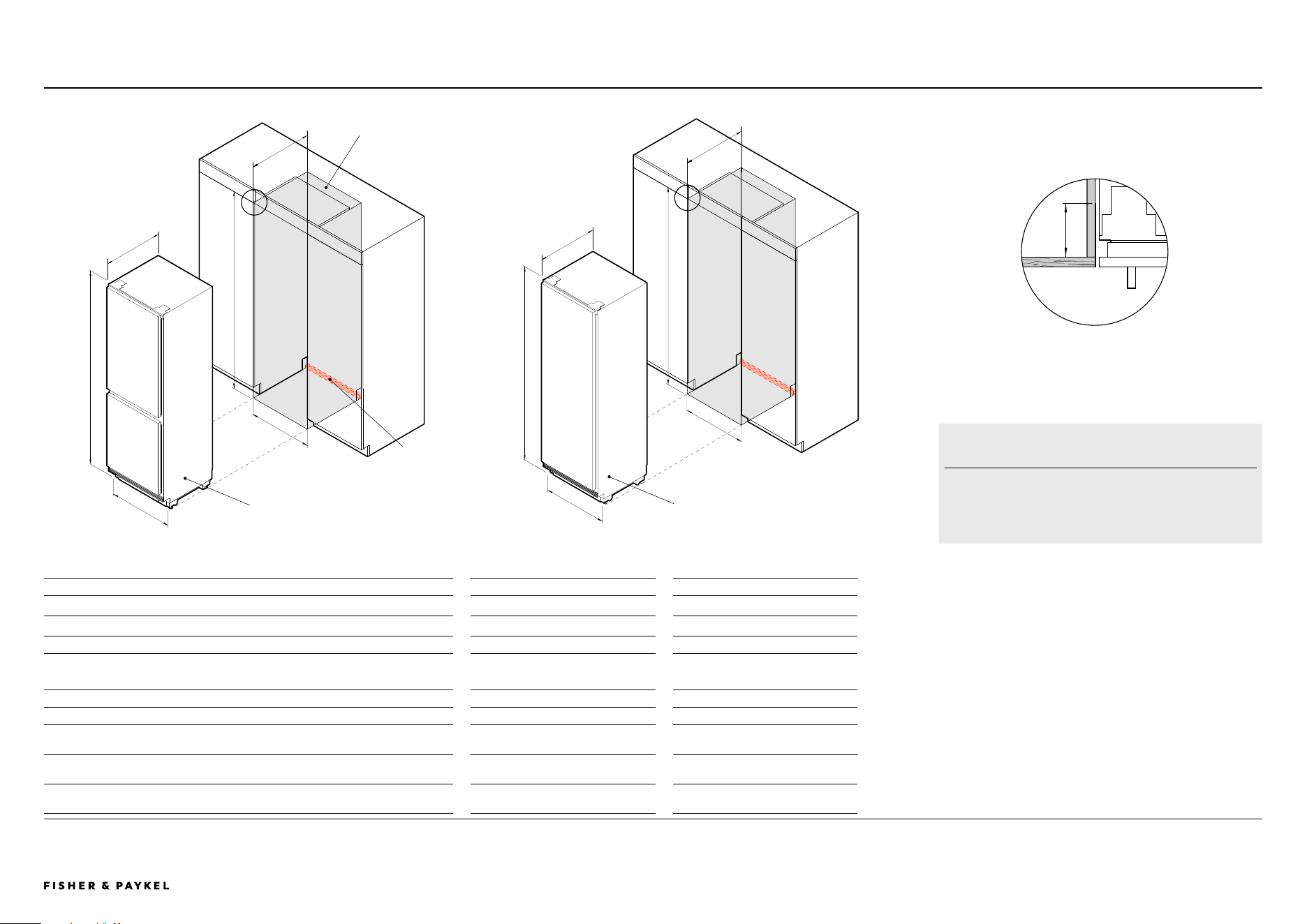
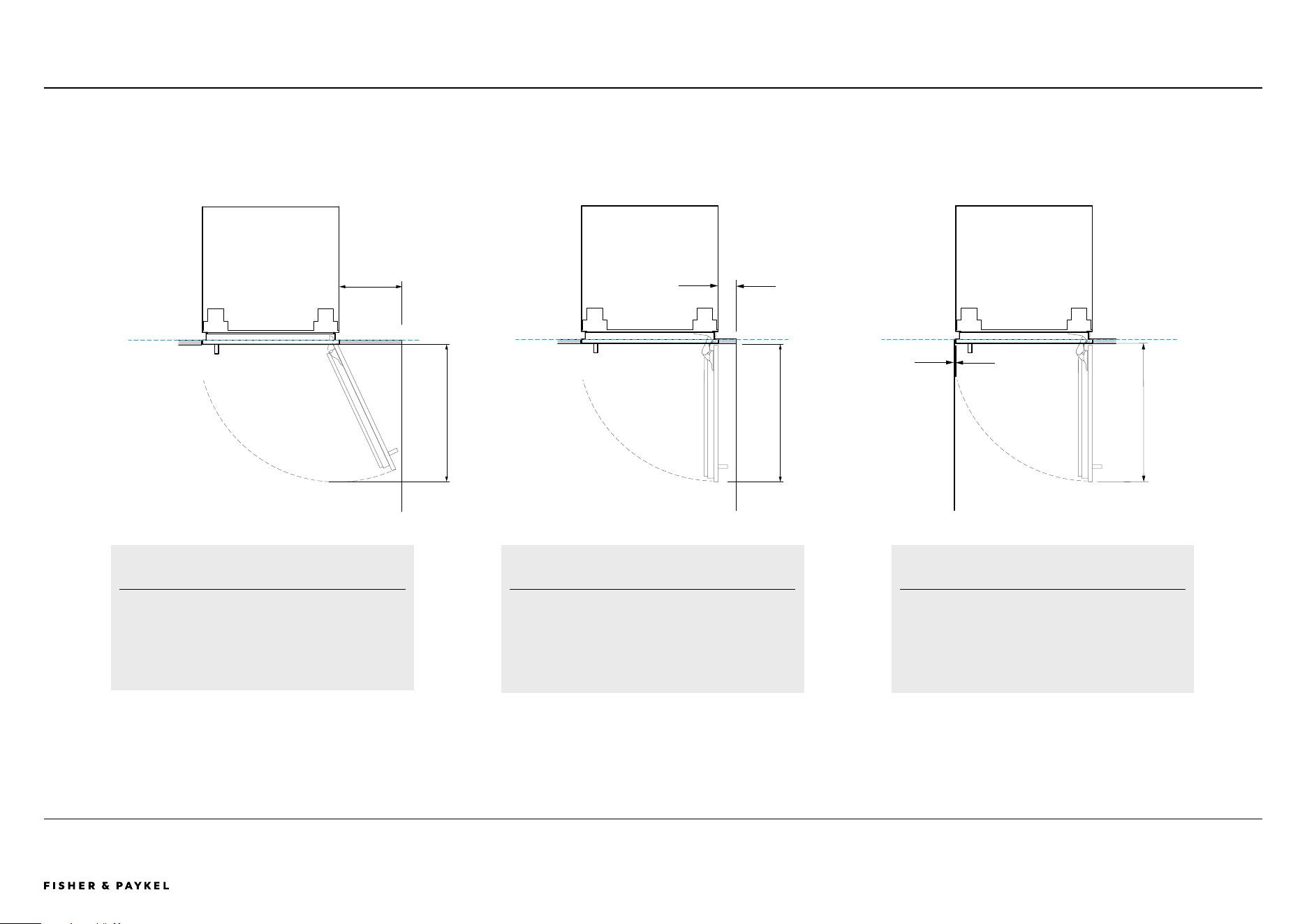
Door Opening Clearance
PLANNING CONSIDERATIONS | DOOR OPENING CLEARANCE
80mm
273mm
600mm
4mm
FULL INTERNAL ACCESS
115° door opening – full internal access
Minimum dimensions shown are for the contemporary handle
AHD5RDB19(B). Custom door panel and handle details need to
be taken into account
REDUCED INTERNAL ACCESS
Use hinge limiting pin to restrict door opening to 90° where
necessary
Minimum dimensions shown are for the contemporary handle
AHD5RDB19(B). Custom door panel and handle details need to
be taken into account
REDUCED INTERNAL ACCESS
Use hinge limiting pin to restrict door opening to 90° where
necessary
Minimum dimensions shown are for the contemporary handle
AHD5RDB19(B). Custom door panel and handle details need to
be taken into account
600mm600mm
RS6019BRU1 | RS6019S2R1 | RS6019S3RH1 | RS6019F2L1 | RS6019F3LJ1
<< CONTENTS
The models shown in this Planning Guide may not be available in all markets and are subject to change at any time. Product specifications may vary from those shown. This Planning Guide should not be used as installation guidance for any
product. Further information is required to safely and correctly install the products featured here. Specific installation guidance will be available on our website fisherpaykel.com
© FISHER & PAYKEL LIMITED 2024 PAGE 2790002833C PLANNING GUIDE REFRIGERATION - VERSION C - OCTOBER 2024
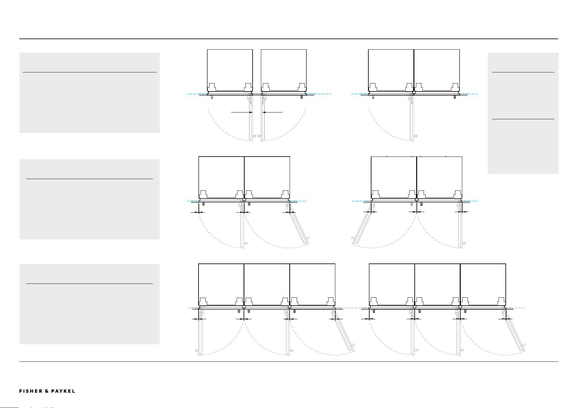
PLANNING CONSIDERATIONS | DOOR OPENING CLEARANCE
cc c cc c
dd d dd dd d
HINGE TO HINGE
A Both doors open at the same time – requires space between
models
B Only allows a single door open at a time
Minimum dimensions shown are for the contemporary handle
AHD5RDB19(B). Custom door panel and handle details need to be
taken into account
Min 100mm
A B
DUAL INSTALLATION
c Stainless steel door panels
(gaps equalized during installation) – 5mm
c Custom door panels
(width of custom door panel increased to maintain 4mm gap
across multiple products) – 4mm
TRIPLE INSTALLATION
d Stainless steel door panels
(gaps equalized during installation) – 6mm
d Custom door panels
(width of custom door panel increased to maintain 4mm gap
across multiple products) – 4mm
ADDITIONAL NOTES
Use hinge limiting pin to
restrict door opening to 90°
where necessary.
Minimum dimensions shown
are for the contemporary
handle AHD5RDB19(B).
Custom door panel and handle
details need to be taken into
account.
RS6019BRU1 | RS6019S2R1 | RS6019S3RH1 | RS6019F2L1 | RS6019F3LJ1
<< CONTENTS

© FISHER & PAYKEL LIMITED 2024 PAGE 2890002833C PLANNING GUIDE REFRIGERATION - VERSION C - OCTOBER 2024
SERVICES
Services
The models shown in this Planning Guide may not be available in all markets and are subject to change at any time. Product specifications may vary from those shown. This Planning Guide should not be used as installation guidance for any
product. Further information is required to safely and correctly install the products featured here. Specific installation guidance will be available on our website fisherpaykel.com
© FISHER & PAYKEL LIMITED 2024 PAGE 2990002833C PLANNING GUIDE REFRIGERATION - VERSION C - OCTOBER 2024
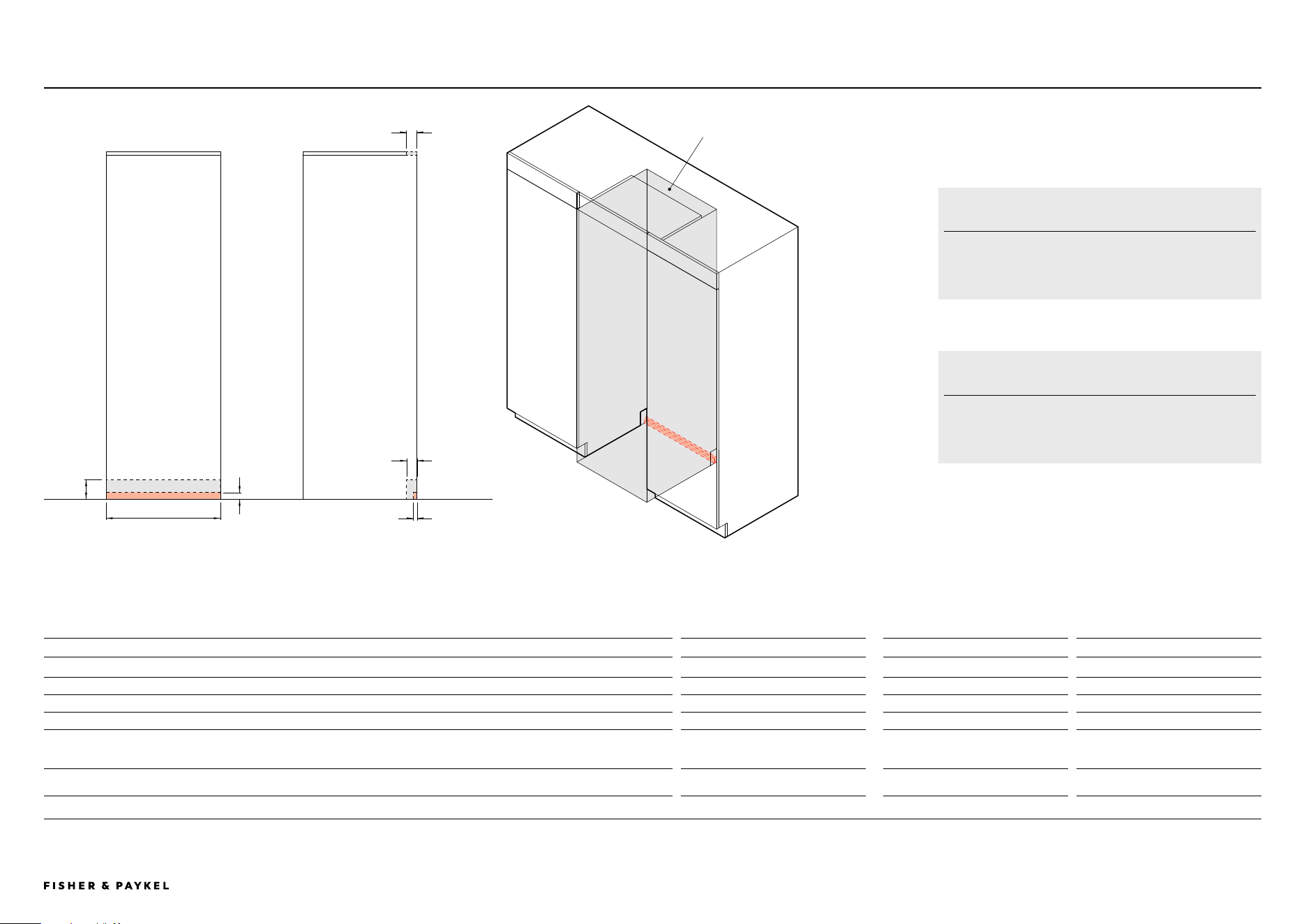
SERVICES | SERVICE AREA AND ELECTRICAL
Service Area and Electrical
Alternative area above cavity
for electrical and plumbing
connection
PROFILE VIEWFRONT VIEW
SERVICE AREA CLEARANCES ELECTRICAL
Dimensions mm
A Overall height of supply routing area at rear of cavity 37 Supply 230 V, 50 Hz
B Overall width of supply routing area at rear of cavity 600 Service 10 A
C Overall depth of supply routing area at rear of cavity 20 Connection Flex cord with plug
D Height of notch at rear of cavity for services to be routed into adjacent cabinet (either side) 100 Plumbing
E Depth of notch at rear of cavity for services to be routed into adjacent cabinet (either side) 55
Supply
UK EU IE SG HK
NZ AU
Braided hose, 7/16" x 24 UNS to 3/4" BSP
Braided hose, 7 x 16-24 UNS to 1/2" BSP
F Minimum depth above cavity for services to be routed through 55 Pressure
min 275 kPa (40 psi)
max 827 kPa (120 psi)
Note: Recommended that services are routed to the adjacent cabinet.
A
B
C
D
E
F
WATER AND ICE
Plumbing is required for models with ice and water.
LOCATION
Recommended that services are routed to the adjacent cabinet or
either side of the product.
RS6019BRU1 | RS6019S2R1 | RS6019S3RH1 | RS6019F2L1 | RS6019F3LJ1
<< CONTENTS
The models shown in this Planning Guide may not be available in all markets and are subject to change at any time. Product specifications may vary from those shown. This Planning Guide should not be used as installation guidance for any
product. Further information is required to safely and correctly install the products featured here. Specific installation guidance will be available on our website fisherpaykel.com
© FISHER & PAYKEL LIMITED 2024 PAGE 3090002833C PLANNING GUIDE REFRIGERATION - VERSION C - OCTOBER 2024
SERVICES | HOSE AND CORD LENGTH
A
FRONT VIEW
B
C F
D E
LEFT-HAND SIDE RIGHT-HAND SIDE
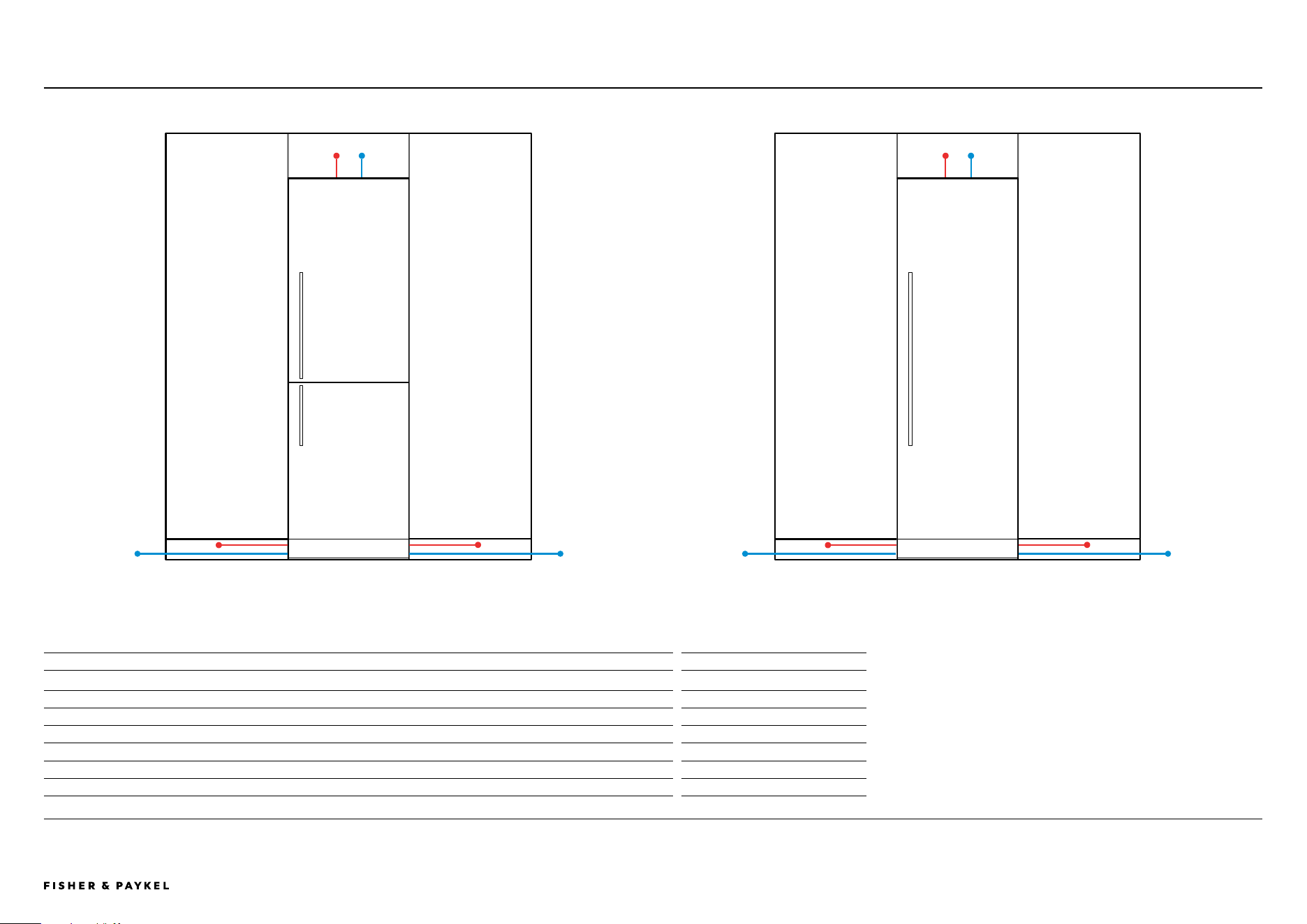
HOSE AND CORD LENGTHS
Electrical mm
A Power cord length (from the left edge of the product)*
1800
B Power cord length (from the right edge of the product)*
2000
C Power cord length (from the top of the product)*
380
Water
D Water inlet hose length (from the left edge of the product)
2450
E Water inlet hose length (from the right edge of the product)
2000
F Water inlet hose length (from the top of the product)
700
*Excluding plug
FRONT VIEW
LEFT-HAND SIDE RIGHT-HAND SIDE
A B
C F
D E
Hose and Cord Length
RS6019S2R1, RS6019S3RH1, RS6019F2L1 or RS6019F3LJ1
RS6019BRU1
RS6019BRU1 | RS6019S2R1 | RS6019S3RH1 | RS6019F2L1 | RS6019F3LJ1
<< CONTENTS

© FISHER & PAYKEL LIMITED 2024 PAGE 3190002833C PLANNING GUIDE REFRIGERATION - VERSION C - OCTOBER 2024
HANDLE DATA SHEETS
Handle Data Sheets
IMPORTANT NOTE: Throughout this guide, dimensions may vary by ±2mm
(1/16''). Please read the Installation Guide for detailed information on
installing the product. For full installation instructions visit fisherpaykel.com
INDICATES PRODUCT DATUM -------------------------------------------
INDICATES CABINETRY CLEARANCES --------------------------------
© FISHER & PAYKEL LIMITED 2024 PAGE 3290002833C PLANNING GUIDE REFRIGERATION - VERSION C - OCTOBER 2024
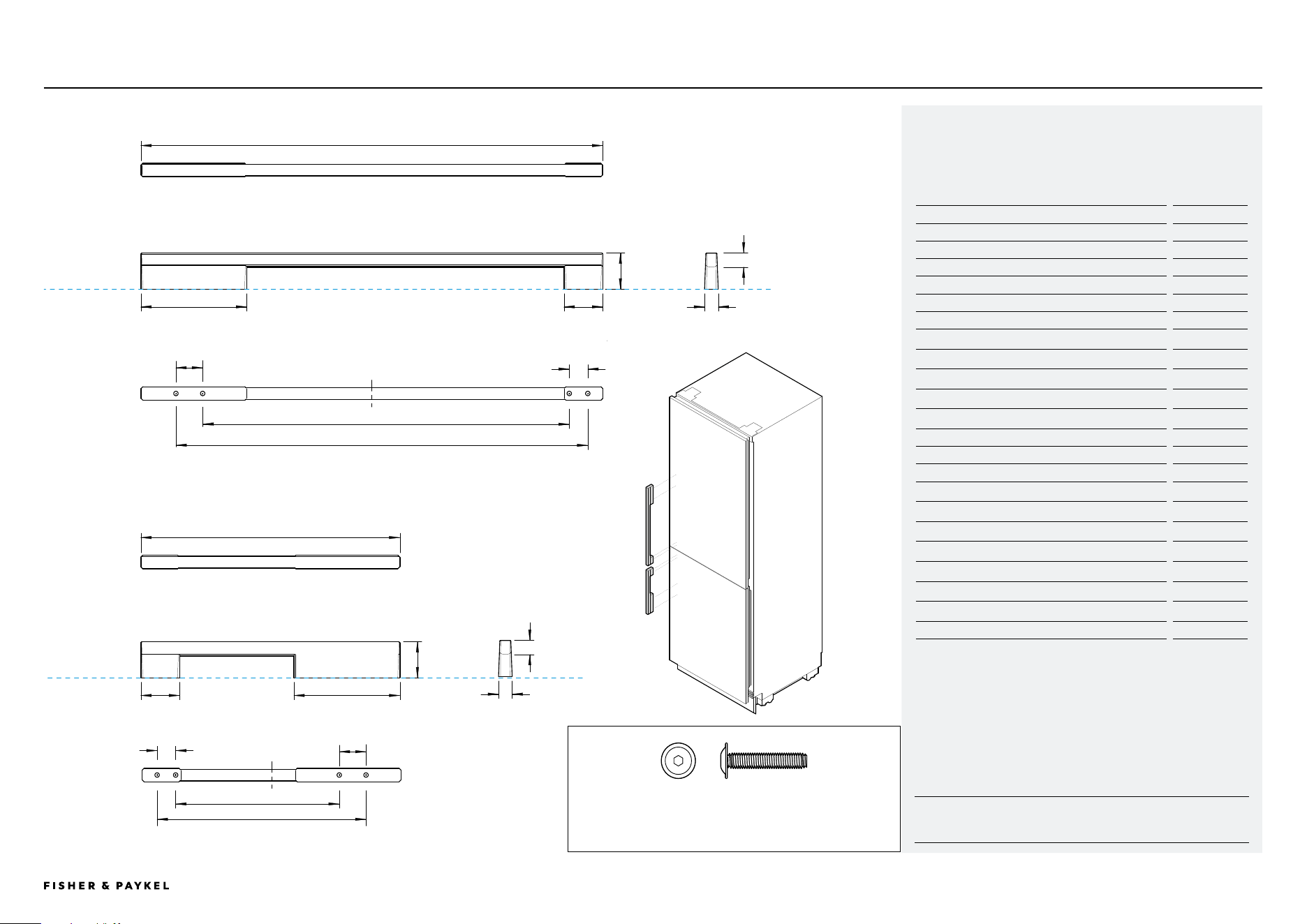
DATA SHEET | SQUARE FINE HANDLE KIT AHD5RDB19 | AHD5RDB19B
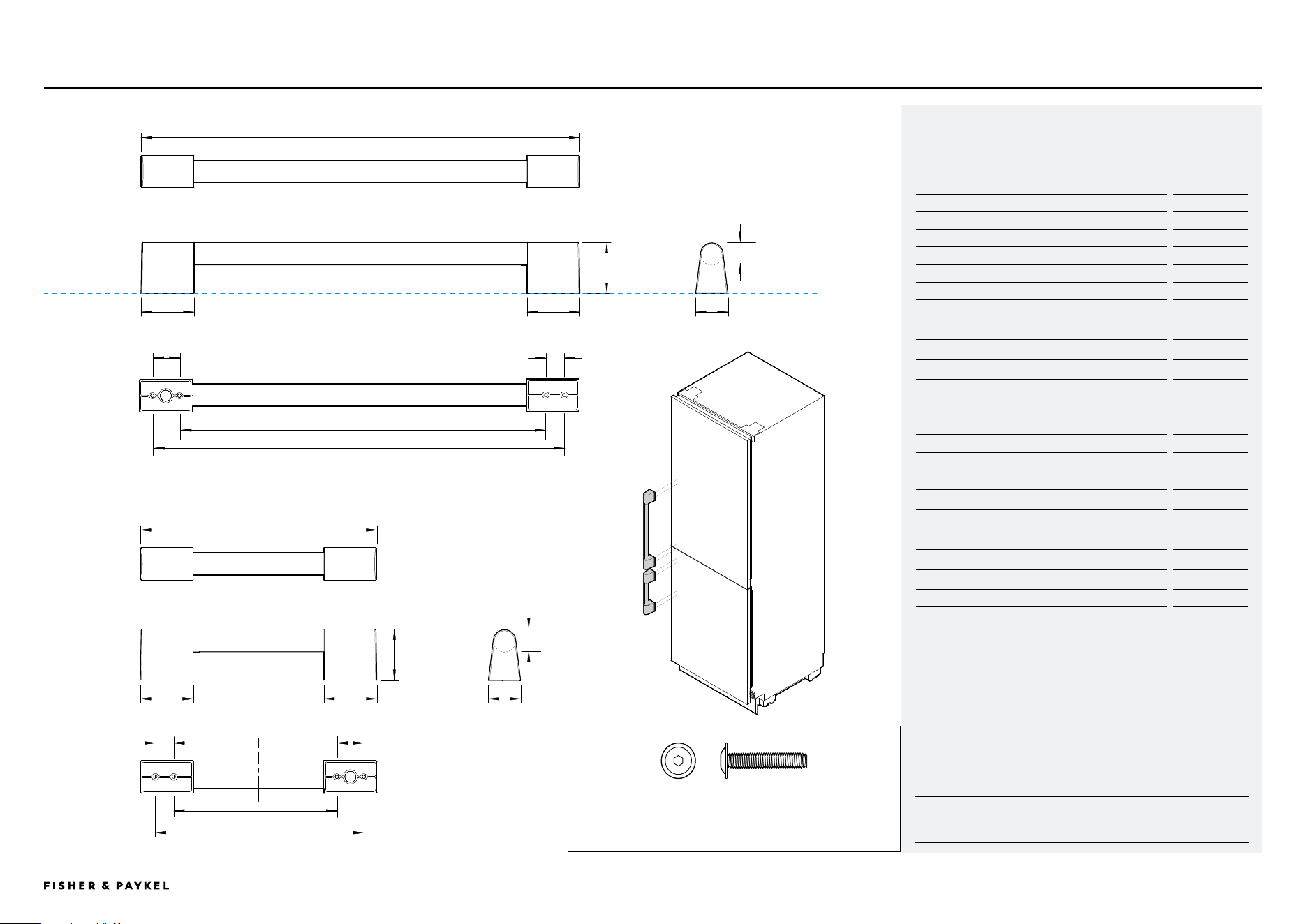
Square Fine Handle Kit
Model no:
Square Fine Aluminium Handle Kit - AHD5RDB19
Square Fine Aluminium Handle Black Kit - AHD5RDB19B
For Model:
Integrated Refrigerator Freezer, 60cm - RS6019BRU1
1 Vertical Handle Top Door Dimensions mm
A Overall length of handle 524
B Overall height of handle 41
C Overall width of handle 16
D Length of off-stand 120
E Length of off-stand 44
F Distance between attachment holes 30
G Distance between attachment holes 21
H Distance between inner attachment holes 395
I Distance between outer attachment holes 436
J Thickness of handle rail 16
2 Vertical Handle Bottom Door Dimensions mm
K Overall length of handle
294
L Overall height of handle
41
M Overall width of handle
16
N Length of off-stand
120
O Length of off-stand
44
P Distance between attachment holes
30
Q Distance between attachment holes
21
R Distance between inner attachment holes
185
S Distance between outer attachment holes
237
T Thickness of handle rail
16
PRODUCT DATUM
1 VERTICAL HANDLE TOP DOOR
2 VERTICAL HANDLE BOTTOM DOOR
M5 X 25mm Pan Head Socket Screw (4 per handle) Suits standard 19mm
panel. Thicker panels may require counterboring or longer screws.
A
B
C
J
ED
H
I
G
F
K
T
M
L
NO
R
S
Q P
2
1
PRODUCT DATUM
<< CONTENTS
IMPORTANT NOTE: Throughout this guide, dimensions may vary by ±2mm
(1/16''). Please read the Installation Guide for detailed information on
installing the product. For full installation instructions visit fisherpaykel.com
INDICATES PRODUCT DATUM -------------------------------------------
INDICATES CABINETRY CLEARANCES --------------------------------
© FISHER & PAYKEL LIMITED 2024 PAGE 3390002833C PLANNING GUIDE REFRIGERATION - VERSION C - OCTOBER 2024
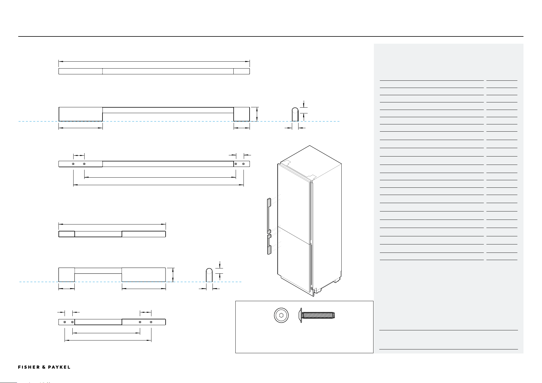
Model no:
Round Handle Kit - AHSRDB19
For Model:
Integrated Refrigerator Freezer, 60cm - RS6019BRU1
1 Vertical Handle Top Door Dimensions mm
A Overall length of handle
524
B Overall height of handle
41
C Overall width of handle
17
D Length of off-stand
120
E Length of off-stand
44
F Distance between attachment holes
30
G Distance between attachment holes
21
H Distance between inner attachment holes
415
I Distance between outer attachment holes
467
J Thickness of handle rail
17
2 Vertical Handle Bottom Door Dimensions mm
K Overall length of handle
294
L Overall height of handle
41
M Overall width of handle
17
N Length of off-stand
120
O Length of off-stand
44
P Distance between attachment holes
30
Q Distance between attachment holes
21
R Distance between inner attachment holes
185
S Distance between outer attachment holes
237
T Thickness of handle rail
17
PRODUCT DATUM
1 VERTICAL HANDLE TOP DOOR
2 VERTICAL HANDLE BOTTOM DOOR
M5 X 25mm Pan Head Socket Screw (4 per handle) Suits standard 19mm
panel. Thicker panels may require counterboring or longer screws.
A
B
C
J
ED
H
I
G
F
K
T
M
L
NO
R
S
Q P
2
1
PRODUCT DATUM
DATA SHEET | ROUND HANDLE KIT AHSRDB19
Round Handle Kit
<< CONTENTS
IMPORTANT NOTE: Throughout this guide, dimensions may vary by ±2mm
(1/16''). Please read the Installation Guide for detailed information on
installing the product. For full installation instructions visit fisherpaykel.com
INDICATES PRODUCT DATUM -------------------------------------------
INDICATES CABINETRY CLEARANCES --------------------------------
© FISHER & PAYKEL LIMITED 2024 PAGE 3490002833C PLANNING GUIDE REFRIGERATION - VERSION C - OCTOBER 2024
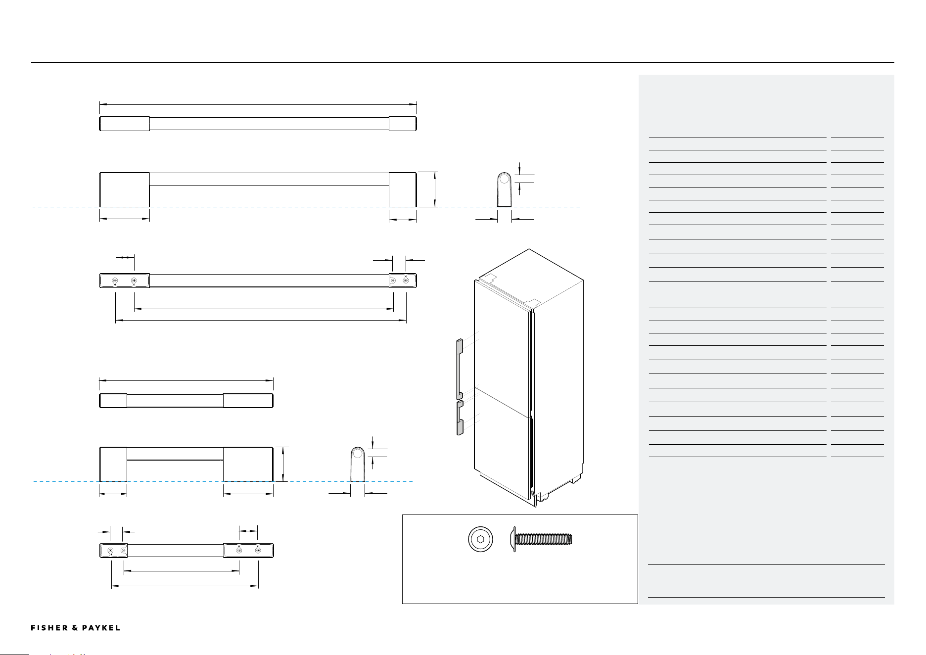
Model no:
Classic Handle Kit- AHCLRDB
For Model:
Integrated Refrigerator Freezer, 60cm - RS6019BRU1
1 Vertical Handle Top Door Dimensions mm
A Overall length of handle
524
B Overall height of handle
55
C Overall width of handle
22
D Length of off-stand
80
E Length of off-stand
44
F Distance between attachment holes
30
G Distance between attachment holes
21
H Distance between inner attachment holes
415
I Distance between outer attachment holes
467
J Thickness of handle rail
20
2 Vertical Handle Bottom Door Dimensions mm
K Overall length of handle
294
L Overall height of handle
55
M Overall width of handle
22
N Length of off-stand
80
O Length of off-stand
44
P Distance between attachment holes
30
Q Distance between attachment holes
21
R Distance between inner attachment holes
185
S Distance between outer attachment holes
237
T Thickness of handle rail
20
PRODUCT DATUM
1 VERTICAL HANDLE TOP DOOR
2 VERTICAL HANDLE BOTTOM DOOR
M5 X 25mm Pan Head Socket Screw (4 per handle) Suits standard 19mm
panel. Thicker panels may require counterboring or longer screws.
A
B
C
J
ED
H
I
G
F
K
T
M
L
NO
R
S
Q
P
2
1
PRODUCT DATUM
DATA SHEET | CLASSIC HANDLE KIT AHCLRDB
Classic Handle Kit
<< CONTENTS
IMPORTANT NOTE: Throughout this guide, dimensions may vary by ±2mm
(1/16''). Please read the Installation Guide for detailed information on
installing the product. For full installation instructions visit fisherpaykel.com
INDICATES PRODUCT DATUM -------------------------------------------
INDICATES CABINETRY CLEARANCES --------------------------------
© FISHER & PAYKEL LIMITED 2024 PAGE 3590002833C PLANNING GUIDE REFRIGERATION - VERSION C - OCTOBER 2024
Model no:
Professional Handle Kit - AHP3RDB19
For Model:
Integrated Refrigerator Freezer, 60cm - RS6019BRU1
1 Vertical Handle Top Door Dimensions mm
A Overall length of handle
499
B Overall height of handle
58
C Overall width of handle
37
D Length of off-stand
60
E Distance between attachment holes
30
F Distance between attachment holes
21
G Distance between inner attachment holes
415
H Distance between outer attachment holes
467
I Thickness of handle rail
25
2 Vertical Handle Bottom Door Dimensions mm
J Overall length of handle
269
K Overall height of handle
58
L Overall width of handle
37
M Length of off-stand
60
N Distance between attachment holes
30
O Distance between attachment holes
21
P Distance between inner attachment holes
185
Q Distance between outer attachment holes
237
R Thickness of handle rail
25
DATA SHEET | PROFESSIONAL HANDLE KIT AHP3RDB19
Professional Handle Kit
PRODUCT DATUM
1 VERTICAL HANDLE TOP DOOR
2 VERTICAL HANDLE BOTTOM DOOR
M5 X 25mm Pan Head Socket Screw (4 per handle) Suits standard 19mm
panel. Thicker panels may require counterboring or longer screws.
A
B
C
I
DD
G
H
F
E
J
R
L
K
MM
P
O
O
N
2
1
PRODUCT DATUM
<< CONTENTS
IMPORTANT NOTE: Throughout this guide, dimensions may vary by ±2mm
(1/16''). Please read the Installation Guide for detailed information on
installing the product. For full installation instructions visit fisherpaykel.com
INDICATES PRODUCT DATUM -------------------------------------------
INDICATES CABINETRY CLEARANCES --------------------------------
© FISHER & PAYKEL LIMITED 2024 PAGE 3690002833C PLANNING GUIDE REFRIGERATION - VERSION C - OCTOBER 2024
Model no:
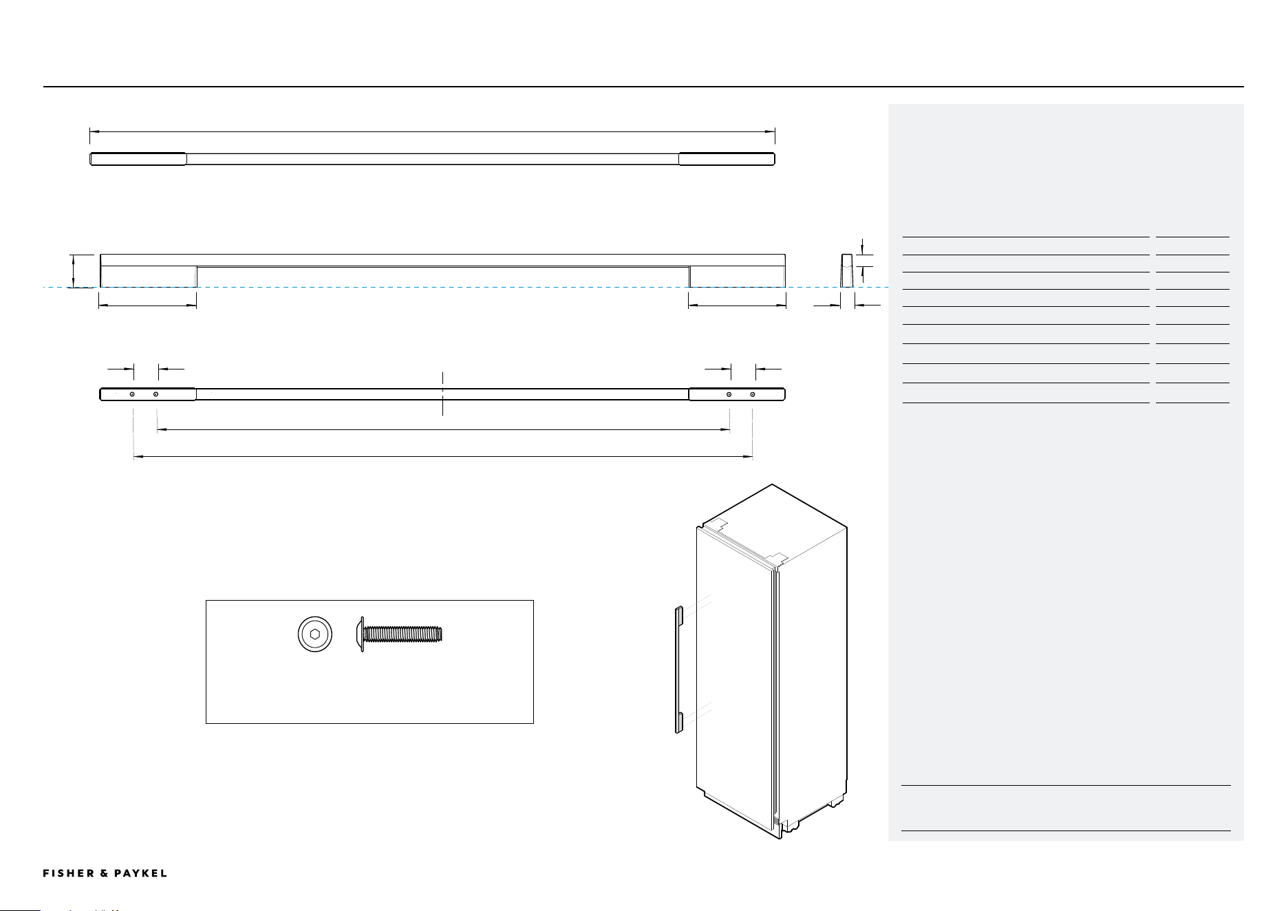
Square Fine Aluminium Handle - AHD5RDSF
Square Fine Aluminium Handle Black - AHD5RDSFB
For Model:
Integrated Refrigerator - RS6019S2R1, RS6019S3RH1
Integrated Freezer - RS6019F2L1, RS6019F3LJ1
Handle Dimensions mm
A Overall length of handle
852
B Overall height of handle
41
C Overall width of handle
15
D Length of off-stand
120
E Distance between attachment holes
30
F Distance between inner attachment holes
712
G Distance between outer attachment holes
773
H Thickness of handle rail
16
DATA SHEET | SQUARE FINE HANDLE AHD5RDSF | AHD5RDSFB
Square Fine Handle
M5 X 25mm Pan Head Socket Screw (4 per handle) Suits standard 19mm
panel. Thicker panels may require counterboring or longer screws.
A
B
C
E
D
H
F
E
G
D
<< CONTENTS
IMPORTANT NOTE: Throughout this guide, dimensions may vary by ±2mm
(1/16''). Please read the Installation Guide for detailed information on
installing the product. For full installation instructions visit fisherpaykel.com
INDICATES PRODUCT DATUM -------------------------------------------
INDICATES CABINETRY CLEARANCES --------------------------------
© FISHER & PAYKEL LIMITED 2024 PAGE 3790002833C PLANNING GUIDE REFRIGERATION - VERSION C - OCTOBER 2024
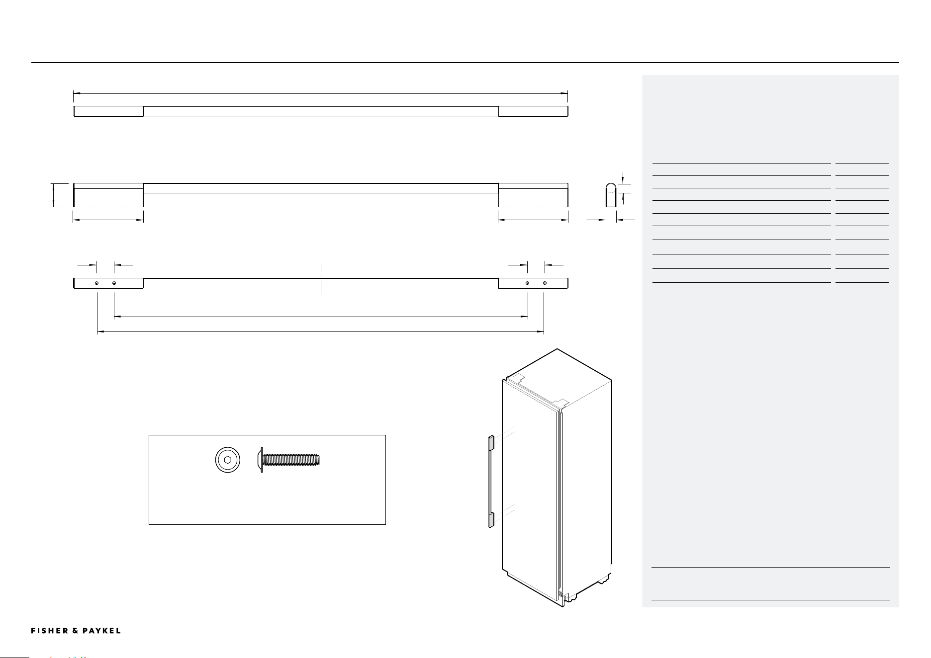
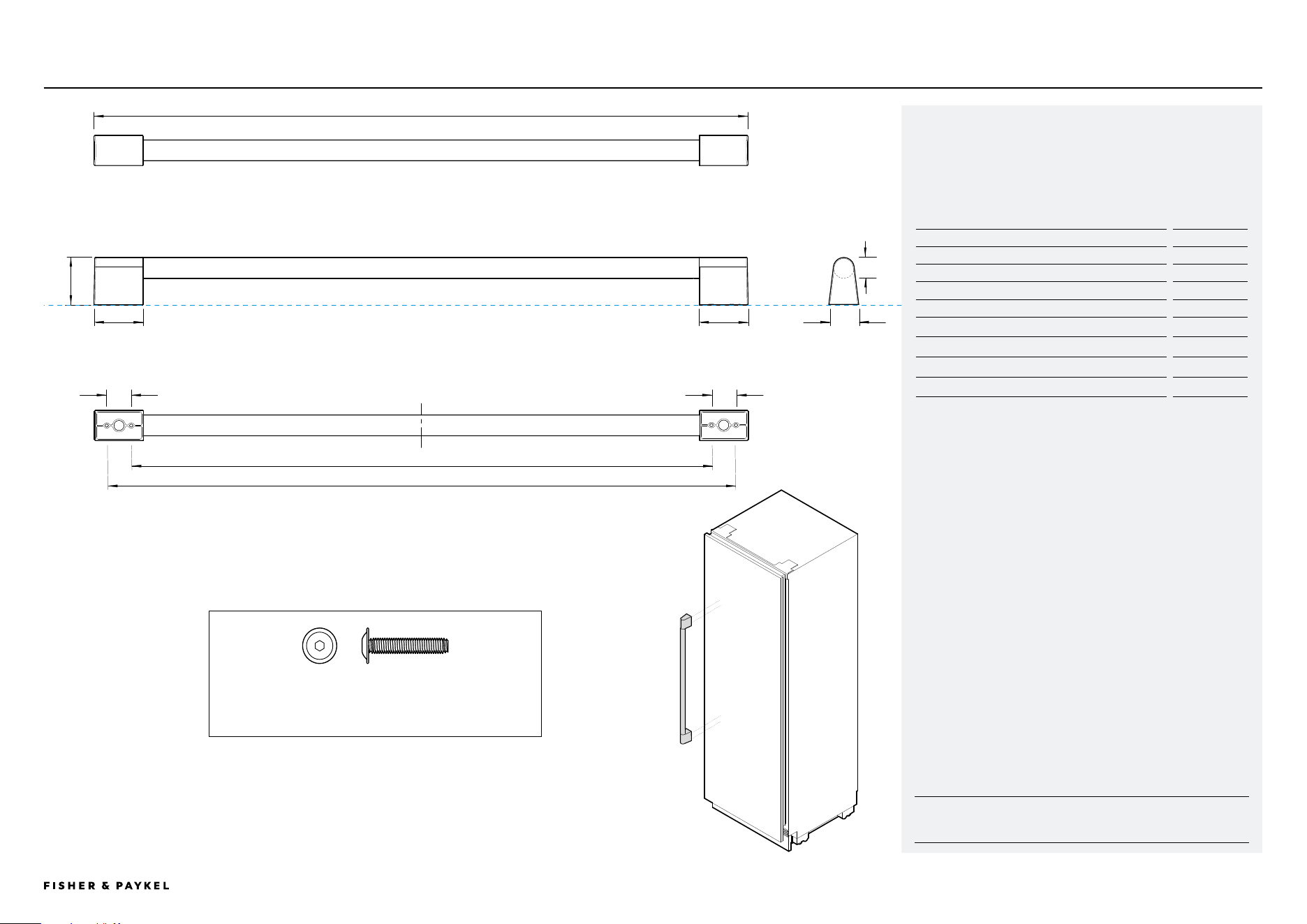
Model no:
Round Handle - AHSRDSF
For Model:
Integrated Refrigerator - RS6019S2R1, RS6019S3RH1
Integrated Freezer - RS6019F2L1, RS6019F3LJ1
Handle Dimensions mm
A Overall length of handle
852
B Overall height of handle
41
C Overall width of handle
17
D Length of off-stand
120
E Distance between attachment holes
30
F Distance between inner attachment holes
712
G Distance between outer attachment holes
773
H Thickness of handle rail
17
DATA SHEET | ROUND HANDLE AHSRDSF
Round Handle
M5 X 25mm Pan Head Socket Screw (4 per handle) Suits standard 19mm
panel. Thicker panels may require counterboring or longer screws.
A
B
C
E
D
H
F
E
G
D
<< CONTENTS
IMPORTANT NOTE: Throughout this guide, dimensions may vary by ±2mm
(1/16''). Please read the Installation Guide for detailed information on
installing the product. For full installation instructions visit fisherpaykel.com
INDICATES PRODUCT DATUM -------------------------------------------
INDICATES CABINETRY CLEARANCES --------------------------------
© FISHER & PAYKEL LIMITED 2024 PAGE 3890002833C PLANNING GUIDE REFRIGERATION - VERSION C - OCTOBER 2024
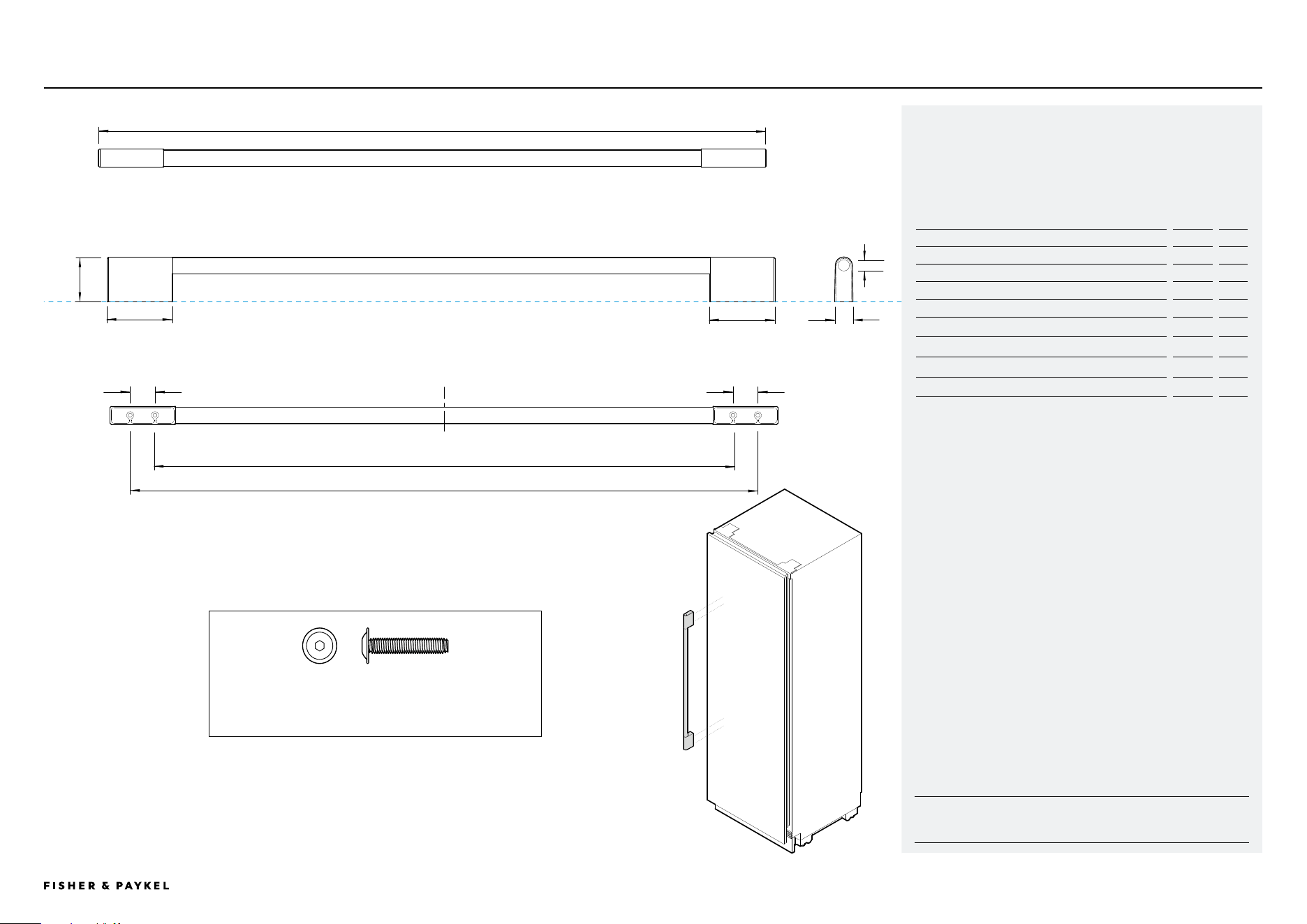
Model no:
Classic Handle - AHCLRDSF
For Model:
Integrated Refrigerator - RS6019S2R1, RS6019S3RH1
Integrated Freezer - RS6019F2L1, RS6019F3LJ1
Handle Dimensions
mm
A Overall length of handle
852
B Overall height of handle
55
C Overall width of handle
22
D Length of off-stand
80
E Distance between attachment holes
30
F Distance between inner attachment holes
712
G Distance between outer attachment holes
773
H Thickness of handle rail
20
DATA SHEET | CLASSIC HANDLE AHCLRDSF
Classic Handle
M5 X 25mm Pan Head Socket Screw (4 per handle) Suits standard 19mm
panel. Thicker panels may require counterboring or longer screws.
A
B
C
E
D
H
F
E
G
D
<< CONTENTS
IMPORTANT NOTE: Throughout this guide, dimensions may vary by ±2mm
(1/16''). Please read the Installation Guide for detailed information on
installing the product. For full installation instructions visit fisherpaykel.com
INDICATES PRODUCT DATUM -------------------------------------------
INDICATES CABINETRY CLEARANCES --------------------------------
© FISHER & PAYKEL LIMITED 2024 PAGE 3990002833C PLANNING GUIDE REFRIGERATION - VERSION C - OCTOBER 2024
Model no:
Professional Handle - AHP3RDSF
For Model:
Integrated Refrigerator - RS6019S2R1, RS6019S3RH1
Integrated Freezer - RS6019F2L1, RS6019F3LJ1
Handle Dimensions mm
A Overall length of handle
802
B Overall height of handle
58
C Overall width of handle
37
D Length of off-stand
60
E Distance between attachment holes
30
F Distance between inner attachment holes
712
G Distance between outer attachment holes
773
H Thickness of handle rail
25
DATA SHEET | PROFESSIONAL HANDLE AHP3RDSF
Professional Handle
M5 X 25mm Pan Head Socket Screw (4 per handle) Suits standard 19mm
panel. Thicker panels may require counterboring or longer screws.
A
B
C
E
D
H
F
E
G
D
<< CONTENTS

© FISHER & PAYKEL LIMITED 2024 PAGE 4090002833C PLANNING GUIDE REFRIGERATION - VERSION C - OCTOBER 2024
