CUB CADET LLC, P.O. BOX 361131 CLEVELAND, OHIO 44136-0019
Printed In USA
Op e r a t O r ’s Ma n u a l
Safe Operation Practices • Contents • Assembly • Calibration • Attachments • Parts List • Warranty
WARNING
READ AND FOLLOW ALL SAFETY RULES AND INSTRUCTIONS IN THIS MANUAL
BEFORE ATTEMPTING TO OPERATE THIS MACHINE.
FAILURE TO COMPLY WITH THESE INSTRUCTIONS MAY RESULT IN PERSONAL INJURY.
Form No. 769-04883
(January 11, 2011)
80 lb. Stainless Steel Rotary Spreader

To The Owner
1
2
Safe Operation Practices ........................................ 3
Assembly & Set-Up .................................................. 9
Controls & Features ................................................12
Operation ................................................................13
Maintenance & Adjustments .................................14
Troubleshooting .....................................................16
Illustrated Parts List ...............................................17
Attachments & Accessories ...................................21
Warranty ................................................................ 24
Table of Contents
Customer Support
If you have difficulty assembling this product or have any questions regarding the controls, operation, or maintenance of
this machine, you can seek help from the experts. Choose from the options below:
Visit us on the web at www.cubcadet.com◊
Locate your nearest Cub Cadet Dealer at (877) 282-8684◊
Write us at Cub Cadet LLC • P.O. Box 361131 • Cleveland, OH • 44136-0019◊
Thank you for purchasing a Cub Cadet Commercial Rotary
Spreader It was carefully engineered to provide excellent
performance when properly operated and maintained.
Please read this entire manual prior to operating the equipment.
It instructs you how to safely and easily set up, operate and
maintain your machine. Please be sure that you, and any other
persons who will operate the machine, carefully follow the
recommended safety practices at all times. Failure to do so could
result in personal injury or property damage.
All information in this manual is relative to the most recent
product information available at the time of printing. Review
this manual frequently to familiarize yourself with the machine,
its features and operation. Please be aware that this Operator’s
Manual may cover a range of product specifications for various
models. Characteristics and features discussed and/or illustrated
in this manual may not be applicable to all models. We reserve
the right to change product specifications, designs and
equipment without notice and without incurring obligation.
If you have any problems or questions concerning the machine,
phone your local Cub Cadet dealer or contact us directly. Cub
Cadet’s Customer Support telephone numbers, web site address
and mailing address can be found on this page. We want to
ensure your complete satisfaction at all times.
Throughout this manual, all references to right and left side of the
machine are observed from the operating position.
Thank You
Record Product Information
Before setting up and operating your new equipment, please
locate the model plate on the equipment and record the
information in the provided area to the right. You can locate the
model plate by standing at the operator’s position and looking
at the back of the hopper. This information will be necessary,
should you seek technical support via our web site or with your
local Cub Cadet dealer.
MO d e l nu M b e r
se r i a l nu M b e r

Important Safe Operation Practices
2
3
General Operation
Read this Operator’s Manual completely before starting the 1.
machine. Study the controls and learn the proper sequence
of operation. Retain Operator’s Manual in a safe place for
future reference.
Do not allow anyone to operate or maintain this machine 2.
who has not read the manual. Never permit children under
the age of 16 to operate this machine.
Always have your feet and hands clear of the controls when 3.
starting the engine.
Do not remove any shields, guards, decals or safety devices. 4.
If a shield, guard, decal or safety device is damaged or
does not function, repair or replace it before operating the
machine.
Always wear safety glasses, long pants and safety shoes 5.
when operating or maintaining this unit. Do not wear
loose-fitting clothing.
Never run the engine indoors without adequate 6.
ventilation. Exhaust fumes are deadly.
To avoid serious burns, do not touch the engine or muffler 7.
while the engine is running or until it has cooled for at least
30 minutes after it has been shut off.
Keep adults, children and pets away from the area to be 8.
spread/sprayed.
Spread/spray only in daylight.9.
Always check the area to be spread/sprayed and remove 10.
debris and other objects prior to spreading/spraying.
Watch for holes, sprinkler heads and other hidden hazards.11.
Reduce speed when making sharp turns.12.
WARNING: This symbol points out important safety instructions which, if not followed,
could endanger the personal safety and/or property of yourself and others. Read and follow
all instructions in this manual before attempting to operate this machine. Failure to comply
with these instructions may result in personal injury.
When you see this symbol. HEED ITS WARNING!
DANGER: This machine was built to be operated according to the safe operation practices in
this manual. As with any type of power equipment, carelessness or error on the part of the
operator can result in serious injury. This machine is capable of amputating fingers, hands,
toes and feet and throwing objects. Failure to observe the following safety instructions could
result in serious injury or death.
WARNING - FOR THE STATE OF CALIFORNIA: A person shall not sell, offer for sale, lease, or
rent to a person any equipment that is powered by an internal combustion engine subject to
Section 4442 or 4443, and not subject to Section 13005 of Health and Safety Code, unless
that equipment has a permanent writing label attached that is in plain view to the operator
that states, ‘WARNING-Operation of This Equipment May Create Sparks That Can Start Fires
Around Dry Vegetation. A Spark Arrestor May be Required. The Operator Should Contact
Local Fire Agencies For Laws or Regulations Relating to Fire Prevention Requirements.’
CALIFORNIA PROPOSITION 65
WARNING: Engine Exhaust, some of its constituents, and certain vehicle components
contain or emit chemicals known to State of California to cause cancer and birth defects
or other reproductive harm.
WARNING: Battery posts, terminals, and related accessories contain lead and lead
compounds, chemicals known to the State of California to cause cancer and reproductive
harm. Wash hands after handling.

4 se c t i O n 2 — iM p O r t a n t sa f e Op e r a t i O n pr a c t i c e s
Always have proper footing on slopes and hill sides and 13.
never operate when conditions are slippery. Be very careful
on wet grass.
Always keep both hands on the handles.14.
Be careful when crossing gravel paths or road- ways.15.
Never leave the machine unattended without placing the 16.
ground speed control levers in neutral, engaging the park
brake, shutting off the engine and closing the fuel shutoff
valve.
Always park the unit and start the engine on a level surface 17.
with the ground speed control levers in neutral, and the
park brake engaged.
If you hit a solid object while spreading/spraying, place the 18.
ground speed control levers in neutral, engage the park
brake and stop the engine. Disconnect the spark plug wire
and inspect for damage. Repair any damage.
Do not operate machine on excessively steep (more than 19.
15 degrees) slopes. Go laterally or diagonally across the
slope, not up and down the slope.
Always disconnect the spark plug wire to prevent the 20.
engine from accidentally starting before performing any
maintenance on this machine.
Keep the machine and especially the engine/pump area 21.
clean and free of grease, grass and leaves to reduce the
potential for over heating and fire.
The speed and direction control levers located on the 22.
handle are designed for your safety. Do not modify them or
operate the machine if they are damaged.
General Requirements
Personal Protective Equipment (PPE):
OSHA Standard 1910.132 through 1910.139
OSHA standard 1910.132 states in relevant part:23.
Protective equipment, including personal a.
protective equipment or PPE, for eyes, face, head,
and extremities, protective clothing, respiratory
devices, and protective shields and barriers, shall
be provided, used, and maintained in a sanitary
and reliable condition where ever it is necessary
by reason of hazards of processes or environment,
chemical hazards, radiological hazards, or
mechanical irritants encountered in a manner
capable of causing injury or impairment in the
function of any part of the body through absorption,
inhalation or physical contact.
This standard is subject to change. Please check www.osha.gov
for the latest regulatory updates
General
Sometimes, it is not possible to reduce a hazard by eliminating
it, substituting a less hazardous process or product, making
changes to equipment, or even by changing how you do the job.
That is when you need personal protection.
PPE includes items like gloves, goggles, boots, hearing
protection and respirators. Respirators filter out particles or block
gases and vapors that can harm the respiratory system. With a
surface area well supplied with blood vessels and equal in size to
a tennis court, the lungs are the quickest and most direct route
for absorbing harmful substance into your body.
Note: PPE does not prevent accidents, but it does prevent or
reduce injury and even fatalities when used properly.
Equipment (PPE)
Protective equipment must be selected carefully. Always test
fit the protective equipment to be sure it fits properly and
comfortably. If it is not comfortable — it will not be worn; if it is
not worn — it will not protect. PPE includes:
Respirators•
Chemical-resistant clothing•
Hearing protectors•
Gloves•
Safety goggles and glasses•
Hard hats•
Sensors to detect hazardous substance•
Communication devices used for safe deployment of •
workers
Inhaling pesticide fumes and mists is a very common entry route
of pesticides into the body. Absorption through the lungs is great
and the sensitivity is high.
The National Institute for Occupational Safety and Health
(NIOSH), under authority of the Federal Mine Safety and Health
Act of 1977 and the Occupational Safety and Health Act of 1970,
tests, approves, and certifies respiratory equipment as being safe
for its intended purpose.
Note: Always be certain that the NIOSH compliance number is
on the product before purchasing respiratory equipment.
Two systems of respiratory protection are available, depending
on the type of respiratory risk involved: air-purification (filtering)
and air-supplying. For most pesticide work, the air-purifying
equipment is adequate and safe.
Protective equipment is usually required by the pesticide label in
one form or another and is integral to safe pesticide application.
Chemical-protective clothing consists of multi-layered garments
made out of various materials that protect against a variety
of hazards. Because no single material can protect against all
chemicals, multiple layers of various materials usually are used
to increase the degree of protection. Protection is maximized
by total encapsulation (completely covering the wearer). An
assortment of types of chemical-protective hats, hoods, gloves,
and boot covers are used with the garments.
There are many brands and models of protective equipment
available for use in pesticide application. Price is not always an
indicator of quality, so shop carefully.

5se c t i O n 2 — iM p O r t a n t sa f e Op e r a t i O n pr a c t i c e s
Note: Select equipment that is NIOSH tested and approved.
Protective equipment, appropriate for the task and hazards
that an employee could be potentially exposed to, shall be
provided by the employer. Since comfort and proper fit must
be considered, the person who is going to use it must select the
proper size to ensure correct fit and function. Unused protective
equipment does not help anyone.
Note: Many supply centers, hardware stores, chemical retailers,
and equipment/machinery dealers keep protective equipment
in stock.
Training
Written procedures shall be developed for PPE use. These
procedures shall include all information and guidance necessary
for their proper selection, use and care. The employer shall
provide fitting instructions including demonstrations and
practice in how the PPE should be worn, It is essential that both
supervisors and workers be properly instructed in PPE selection,
use, and maintenance. Training shall provide the workers an
opportunity to handle PPE, and have it fitted properly.
When to replace PPE
All PPE shall be inspected routinely before and after each use. A
program for maintenance and care of PPE shall be initiated and
be adjusted to the type of work place, working conditions, and
hazards. It shall include the following:
Inspection for defects and damage•
Cleaning and disinfecting•
Repair•
Storage•
Many factors influence how long PPE (especially respirators)
remains effective. As well as hours of use, an air-purifying
respirator’s service life is affected by the concentration of dust
and other contaminants in the environment; the user’s body size;
how strenuously the user works while the respirator is worn; and
how the respirator is stored.
Note: As a result, it’s not possible to specify a length of time
after which a respirator should be replaced.
In general, replace a mask or filter when it is visibly dirty or
damaged, or when you experience difficulty breathing through
it. Replace respirator cartridges when you can smell or taste
chemical while or after using the respirator, or according to
the manufacturer’s recommendations. Replacement or repairs
shall be done only by experienced person with parts designed
for the PPE. No attempts shall be made to replace components
or to make adjustments or repairs beyond the manufacturer’s
recommendations.
Slope Operation
Slopes are a major factor related to loss of control and tip-over
accidents, which can result in severe injury or death.
CAUTION: All slopes require extra caution. If you
cannot back up the slope or if you feel uneasy on it,
do not make any turns on it.
For your safety, use the slope gauge included in this section to
measure slopes before operating this unit on a sloped or hilly
area. If the slope is greater than 15 degrees as shown on the
slope gauge, do not operate this unit on that area or serious
injury could result.
DO:
Go across slopes, not up and down.•
Remove obstacles such as rocks, limbs, etc.•
Watch for holes, ruts or bumps. Uneven terrain could •
overturn the machine. Tall grass can hide obstacles.
Use slow speed. Choose a low enough speed so that you •
will not have to stop while on the slope.
Follow the manufacture’s recommendations for •
counterweights with attachments to improve stability.
Keep all movement on the slopes slow and gradual. Do •
not make sudden changes in speed or direction. Rapid
acceleration or deceleration could cause the front of the
machine to lift and rapidly flip over backwards, which could
cause serious injury.
Avoid starting or stopping on a slope. If the tires lose •
traction, disengage the blades and proceed slowly straight
down the slope.
DO NOT:
Do not turn on slopes unless necessary; then, turn slowly •
and use extra care.
Do not operate near drop-offs, ditches or embankments. •
The unit could suddenly turn over if a wheel is over the edge
of a cliff or ditch, or if an edge caves in.
Do not operate on wet grass. Reduced traction could cause •
sliding.
Do not try to stabilize the machine by putting your foot on •
the ground.
Transporting Machines
Machines operated on public roads must comply with state •
& local ordinances, SAE J137, and ANSI/ASABE S279.
Use care when loading or unloading machines onto trailers •
and trucks.
If ramps are used, they must be full width, and secured to •
the trailer or truck.
Machines must be secured onto trailers and trucks with •
straps, chains, cables, ropes, or other means deemed
adequate for that purpose. The front and rear of the
machines must be secured to the trailer or truck in both the
lateral and vertical directions.
Service
Safe Handling of Gasoline:
To avoid personal injury or property damage use extreme 1.
care in handling gasoline. Gasoline is extremely
flammable and the vapors are explosive. Serious
personal injury can occur when gasoline is spilled on
yourself or your clothes which can ignite. Wash your skin
and change clothes immediately.

6 se c t i O n 2 — iM p O r t a n t sa f e Op e r a t i O n pr a c t i c e s
Use only an approved gasoline container.a.
Never fill containers inside a vehicle or on a truck b.
or trailer bed with a plastic liner. Always place
containers on the ground away from your vehicle
before filling.
When practical, remove gas-powered equipment c.
from the truck or trailer and refuel it on the ground.
If this is not possible, then refuel such equipment on
a trailer with a portable container, rather than from a
gasoline dispenser nozzle.
Keep the nozzle in contact with the rim of the fuel d.
tank or container opening at all times until fueling is
complete. Do not use a nozzle lock-open device.
Extinguish all cigarettes, cigars, pipes and other e.
sources of ignition.
Never fuel machine indoors.f.
Never remove gas cap or add fuel while the engine g.
is hot or running. Allow engine to cool at least two
minutes before refueling.
Never over fill fuel tank. Fill tank to no more than 1 h.
inch below bottom of filler neck to allow space for
fuel expansion.
Replace gasoline cap and tighten securely.i.
If gasoline is spilled, wipe it off the engine and j.
equipment. Move machine to another area. Wait 5
minutes before starting the engine.
To reduce fire hazards, keep machine free of grass, k.
leaves, or other debris build-up. Clean up oil or fuel
spillage and remove any fuel soaked debris.
Never store the machine or fuel container inside l.
where there is an open flame, spark or pilot light
as on a water heater, space heater, furnace, clothes
dryer or other gas appliances.
Allow a machine to cool at least five minutes before m.
storing.
General Service
Never run an engine indoors or in a poorly ventilated area. 1.
Engine exhaust contains carbon monoxide, an odorless,
and deadly gas.
Before cleaning, repairing, or inspecting, make certain all 2.
moving parts have stopped. Disconnect the spark plug
wire and ground against the engine to prevent unintended
starting.
Keep all nuts, bolts, and screws tight to be sure the 3.
equipment is in safe working condition.
After striking a foreign object, stop the engine, disconnect 4.
the spark plug wire(s) and ground against the engine.
Thoroughly inspect the machine for any damage. Repair
the damage before starting and operating.
Never attempt to make adjustments or repairs to the 5.
machine while the engine is running.
For safety protection, frequently check components 6.
and replace immediately with original equipment
manufacturer’s (O.E.M.) parts only, listed in the parts
manual. “Use of parts which do not meet the original
equipment specifications may lead to improper
performance and compromise safety!”
Do not change the engine governor settings or over-speed 7.
the engine. The governor controls the maximum safe
operating speed of the engine.
Maintain or replace safety and instruction labels, as 8.
necessary.
Observe proper disposal laws and regulations for gas, oil, 9.
etc. to protect the environment.
Do not modify engine
To avoid serious injury or death, do not modify engine in any
way. Tampering with the governor setting can lead to a runaway
engine and cause it to operate at unsafe speeds. Never tamper
with factory setting of engine governor.
Notice Regarding Emissions
Engines which are certified to comply with California and federal
EPA emission regulations for SORE (Small Off Road Equipment)
are certified to operate on regular unleaded gasoline, and
may include the following emission control systems: Engine
Modification (EM), Oxidizing Catalyst (OC), Secondary Air
Injection (SAI) and Three Way Catalyst (TWC) if so equipped.
Spark Arrestor
WARNING! This machine is equipped with an
internal combustion engine and should not be used
on or near any unimproved forest-covered, brush
covered or grass-covered land unless the engine’s
exhaust system is equipped with a spark arrestor
meeting applicable local or state laws (if any).
If a spark arrestor is used, it should be maintained in effective
working order by the operator. In the State of California the
above is required by law (Section 4442 of the California Public
Resources Code). Other states may have similar laws. Federal laws
apply on federal lands.
A spark arrestor for the muffler is available through your
nearest engine authorized service dealer or contact the service
department, P.O. Box 361131 Cleveland, Ohio 44136-0019.
7se c t i O n 2 — iM p O r t a n t sa f e Op e r a t i O n pr a c t i c e s
WARNING: Your Responsibility—Restrict the use of this power machine to persons who read, understand and
follow the warnings and instructions in this manual and on the machine.
SAVE THESE INSTRUCTIONS!
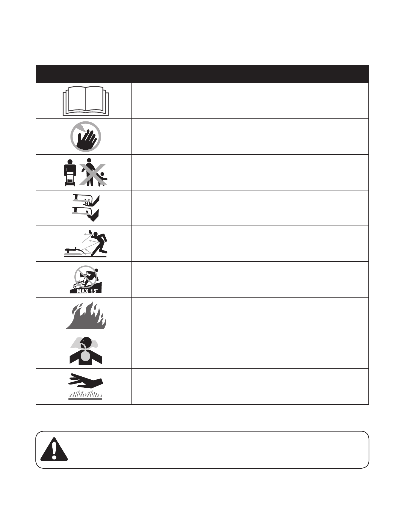
Safety Symbols
This page depicts and describes safety symbols that may appear on this product. Read, understand, and follow all instructions on the
machine before attempting to assemble and operate.
Symbol Description
READ THE OPERATOR’S MANUAL(S)
Read, understand, and follow all instructions in the manual(s) before attempting to
assemble and operate
DANGER — ROTATING BLADES
To reduce the risk of injury, keep hands and feet away. Do not operate unless discharge cover
or grass catcher is in its proper place. If damaged, replace immediately.
DANGER — BYSTANDERS
Do not mow when children or others are around.
DANGER — HAND/ FOOT CUT
Keep hands and feet away from rotating parts.
DANGER — THROWN DEBRIS
Remove objects that can be thrown by the blade in any direction. Wear safety glasses.
DANGER — SLOPES
Use extra caution on slopes. Do not mow slopes greater than 15°.
WARNING—GASOLINE IS FLAMMABLE
Allow the engine to cool at least two minutes before refueling.
WARNING— CARBON MONOXIDE
Never run an engine indoors or in a poorly ventilated area. Engine exhaust contains carbon
monoxide, an odorless and deadly gas.
WARNING— HOT SURFACE
Engine parts, especially the muffler, become extremely hot during operation. Allow engine
and muffler to cool before touching.
8 se c t i O n 2 — iM p O r t a n t sa f e Op e r a t i O n pr a c t i c e s
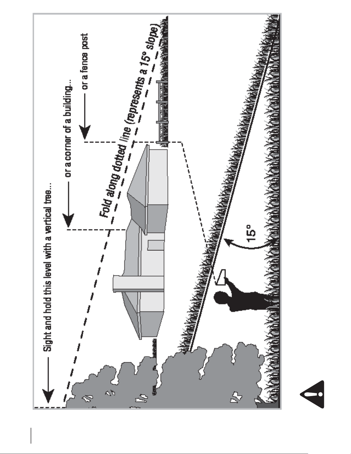
Use this page as a guide to determine slopes where you may not operate safely.
WARNING: Do not operate your machine on such slopes. Do not operate on inclines with a slope in excess of 15 degrees (a
rise of approximately 2-1/2 feet every 10 feet). A riding machine could overturn and cause serious injury. Operate across the
face of slopes, never up and down slopes.
Assembly & Set-Up
3
9
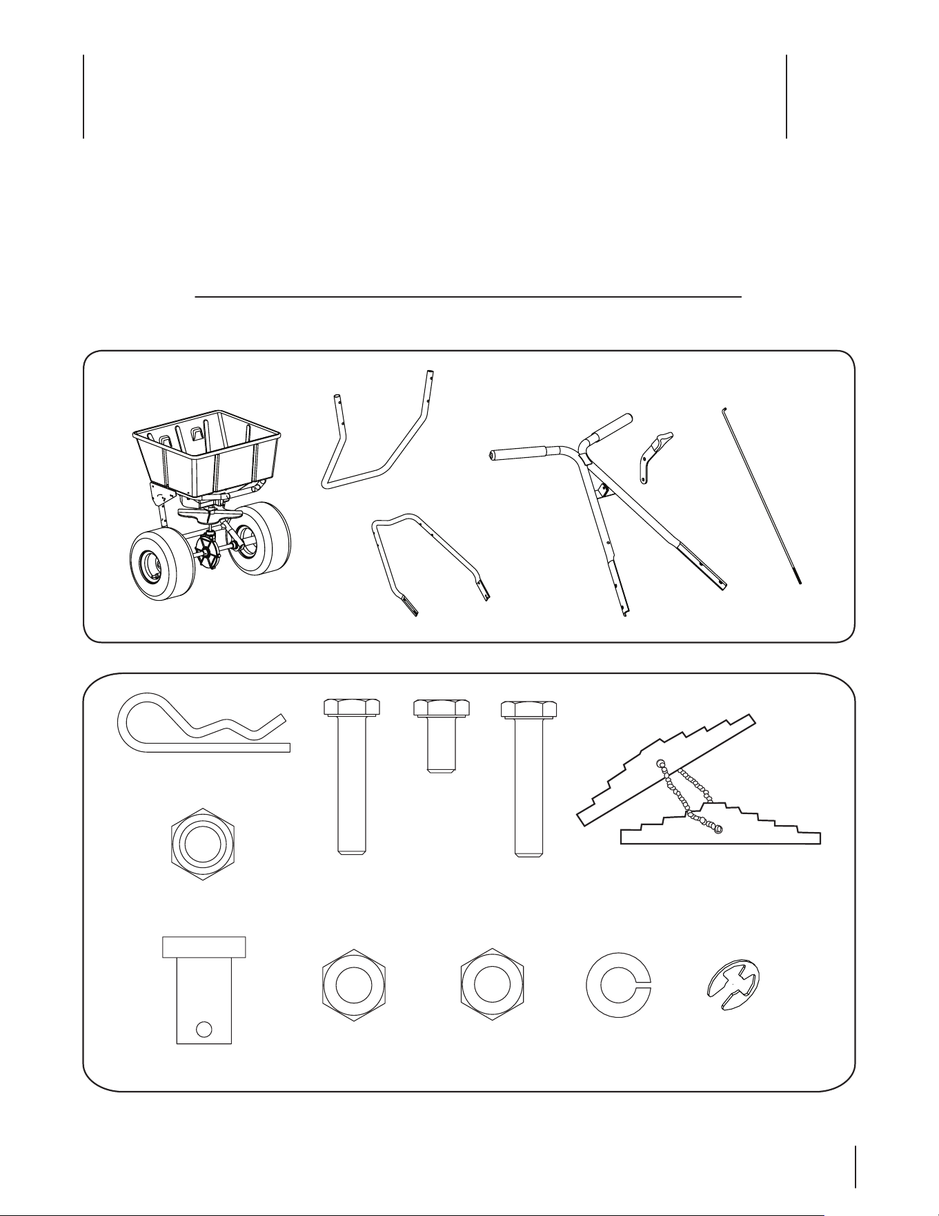
Contents of Carton
One Rotary Spreader Operator’s •
Manual
One Hopper & Frame• One Leg•
One Lower Handle• Two Handle Grips• One Handle Assembly•
One On/Off Lever• One Operating Lever Rod• One Hardware Pack•
Before beginning installation, remove all parts from the carton to make sure everything is present. Carton contents are listed above
and shown in Fig. 3-1. A hardware pack is included in this kit and is detailed in Fig. 3-2.
Hopper and Frame
Leg
Lower Handle
Handle
On/Off
Lever
Operating
Lever Rod
Figure 3-1
Figure 3-2
Clevis Pin (1)
00060031
Hex Nut, 5⁄16-18 (1)
00060071
Bow-Tie Cotter Pin
(1) 00060032
Lock Nut,
5⁄16-18 (1)
00060072
Nut,
1⁄4-20 (12)
00060036
Lock Washer,
5⁄16 (1)
00060073
Retainer
Clip (1)
00010171
Calibration
Gauge (Even)
00009746
Calibration
Gauge (Odd)
00009742
Calibration
Gauge Chain
00009941
Hex Screw,
1⁄4-20 x 3⁄4(4)
00031168
Machine Screw,
1⁄4-20 x 1.5”(4)
00031167
Hex Screw,
1⁄4-20 x 2”(4)
01005552
9
13
17
21
23
23
19
15
11
7
8
12
16
20
24
24
22
18
14
10
6
10 se c t i O n 3 — as s e M b l y & se t -up
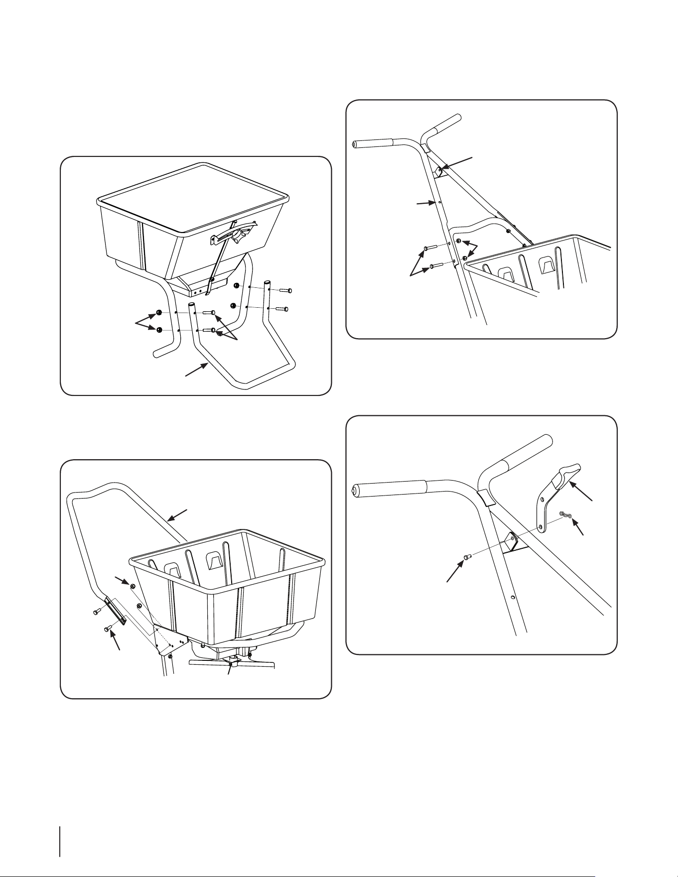
Attach the upper handle to the lower handle (with the On/3.
Off bracket lugs facing up) using four hex screws (1⁄4-20 x
1-1⁄2) and four nuts (1⁄4-20). See Fig. 3-5.
Fasten the On/Off lever to the handles bracket lugs using 4.
the clevis pin in the bottom hole of the lever. Insert the
clevis pin from left to right, facing the rear of the hopper.
Lock with the bow-tie cotter pin (3⁄32 x 1⁄2). See Fig. 3-6.
To assemble and set-up your new spreader, follow the
instructions below:
Note: References to left and right are from the operator’s
position, unless otherwise stated.
Install the leg to the hopper and frame assembly by 1.
fastening with four hex screws (1⁄4-20 x 2) and four nuts
(1⁄4-20). See Fig. 3-3.
Attach the lower handle to the frame (with the “V” section 2.
of the closed section of the handle facing down) using four
hex screws (1⁄4-20 x 3⁄4) and four nuts (1⁄4-20). See Fig. 3-4.
Figure 3-3
Hex
Screws
Nuts
Leg
Lower Handle
Nut
Hex Screw
Figure 3-4
Upper Handle
Hex Screws
Nuts
On/Off Bracket Lugs
Figure 3-5
On/Off
Lever
Bow-Tie
Cotter Pin
Clevis Pin
Figure 3-6
11se c t i O n 3 — as s e M b l y & se t -up
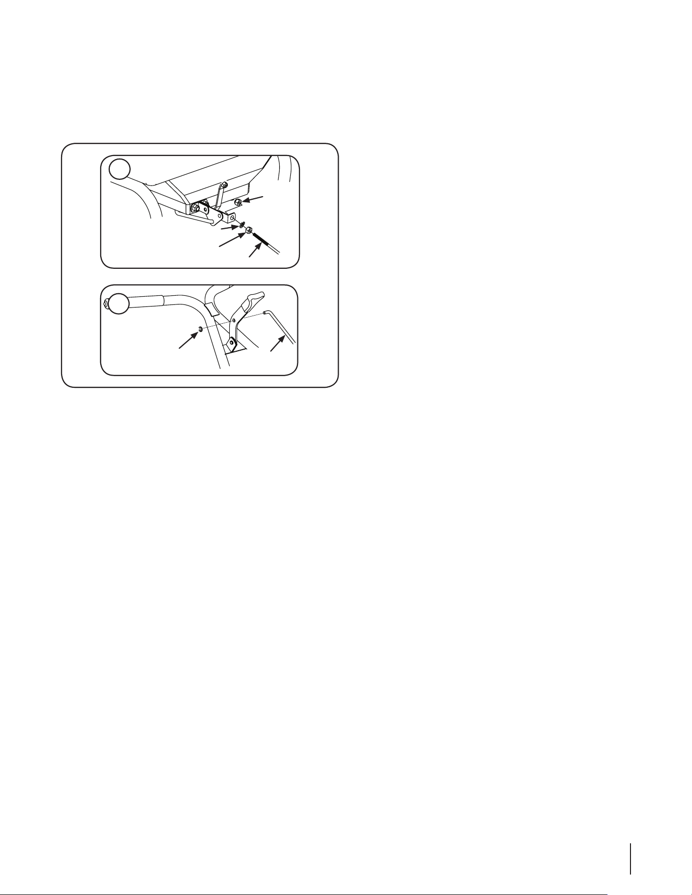
Attach the operating lever rod to the pivot lever assembly 5.
at the bottom-rear of the hopper and the On/Off lever
First screw the a. 5⁄16 hex nut on the threaded end of
the operating lever rod, add the 5⁄16 lock washer, then
insert the rod through the hole in the pivot lever
assembly and install the 5⁄16 lock nut. See Fig. 3-7.
Attach the operating lever rod to the On/Off lever by b.
inserting the bent end of the rod into the top hole
of the lever from left to right and install the retainer
clip. See Fig. 3-7.
Pull the On/Off lever to the “OFF” position and move the 6.
shutoff plate assembly to the fully closed position by
adjusting the 5⁄16 hex nuts on the bottom of the operating
lever rod up or down. Refer to Fig. 3-7.
Grease the axle bearings and the gear support.7.
Read the spreader calibration instructions in the 8.
Maintenance & Adjustments section and calibrate
following the instructions.
Lock
Nut
Lock Washer
Hex Nut
Operating Lever Rod
A
B
Operating
Lever Rod
Retainer Clip
Figure 3-7
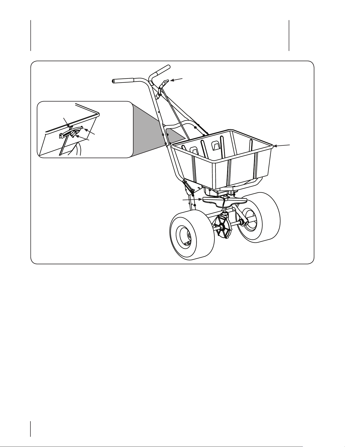
Controls & Features
4
12
On/Off Lever
Hopper
Impeller
Rate Plate
Rate Control Knob
Rate Control Arm
Figure 4-1
The Controls & Features of the 80# Rotary Spreader are discussed
below and illustrated in Fig. 4-1.
On/Off Lever
The On/Off Lever is located on the upper handle and controls the
shutoff plate on the bottom of the Hopper and the discharge of
the product.
Rate Control Arm
The Rate Control Arm is located on the back of the Hopper and
indicates on the Rate Plate the current discharge setting of the
discharge holes.
Rate Control Knob
The Rate Control Knob is located on the back of the Hopper and
is used to secure the Rate Control Arm in the proper discharge
rate. The knob — when loosened — can be used to move the
Rate Control Arm to the desired discharge rate.
Rate Plate
The Rate Plate is located on the back of the Hopper and indicates
the different discharge settings of the spreader.
Impeller
The Impeller is located below the Hopper and distributes the
product as it passes through the discharge holes.
Hopper
Application product is placed in the Hopper to be distributed by
the spreader.
Mesh Screen (Not Shown)
The Mesh Screen is inside the Hopper and helps filter out larger
materials to avoid clogging or damaging the spreader.
Operation
5
13
Using the Rotary Spreader
Check the rate setting on the product package.1.
Adjust the rate setting using the rate plate on the back of 2.
the hopper.
Note: The rate settings on the product packaging is
a recommended starting point. Always check the rate
in a small area before treating a large area. See the
Maintenance & Adjustments section for information on
calibrating the spreader.
Make sure the On/Off Lever is in the “OFF” position and 3.
the mesh screen is in place. Then fill the hopper with the
desired amount of application product.
Note: Always fill the spreader on the driveway or sidewalk,
not on the lawn.
Start walking with the spreader and move the On/Off Lever 4.
into the “ON” position to begin spreading product.
Note: Always push the spreader, never pull.
Note: Keep the handles of the spreader level while
spreading. Tipping the spreader to far to one side or the
other can cause uneven product distribution.
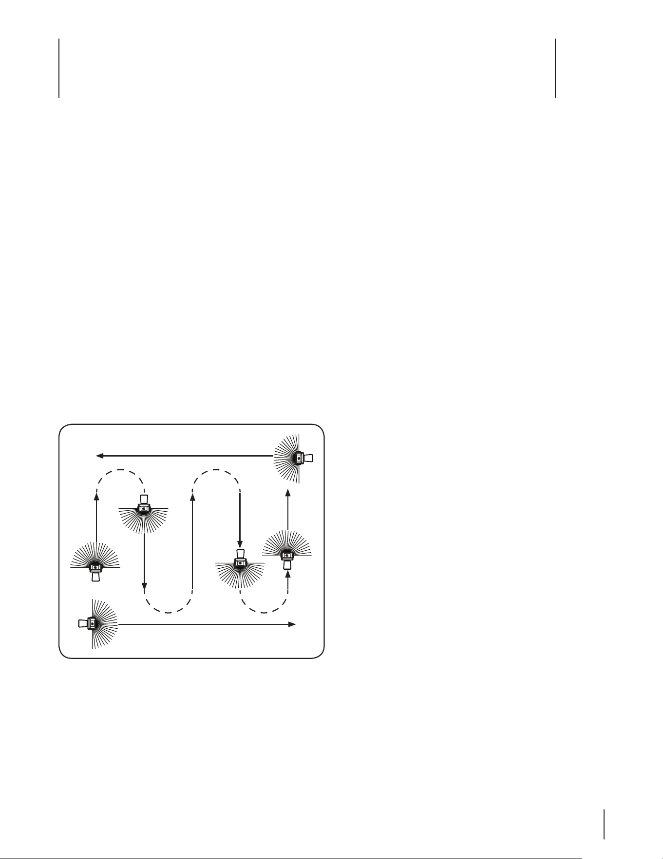
See Fig. 5-1 for a recommended pattern to follow when 5.
using the spreader.
Push the spreader at a consistent speed (approximately 3 6.
m.p.h. is recommended).
Empty the spreader after each use. Wash the spreader 7.
thoroughly and allow it to dry. Keep the impeller clean.
Lubricate all moving parts. Apply grease to the five grease 8.
fittings; two in the axle supports, two in the gear support
and one in the idler wheel (if the idler wheel has a steel
hub).
End
Start
Figure 5-1
Maintenance & Adjustments
6
14
Spreader Calibration
Two items must be considered when calibrating a spreader.
The first is the distribution pattern of the spreader. That is, the
pattern the product makes as it strikes the ground after being
thrown out by the spreader’s impeller. There are many factors
which affect the distribution pattern of a rotary spreader and
some of them relate directly to the product. For this reason, we
recommend that the spreader be calibrated separately for every
product to be applied. Spreader calibration should be checked
at least once a month, or more often when the spreader is used
frequently.
The second item is the product application rate, that is the
amount of product applied per thousand square feet. This is
important because over-application can be costly and may cause
plant injury, while under-application will reduce the effectiveness
of the product.
To Calibrate a Spreader, Follow These Steps:
Check the spreader discharge holes with the operating 1.
lever in the closed position.
If the discharge holes are not fully closed, thread the upper 2.
jam nut on the operating lever rod further up the rod.
Tighten the lower locknut and recheck. Repeat this 3.
procedure until the holes are fully closed.
To Achieve a Uniform Distribution Pattern:
The accurate method for checking pattern uniformity is to lay
out shallow boxes or pans in a row on a line perpendicular to the
direction of spreader travel. Eleven boxes or pans, two inches
high placed on one-foot centers will provide accurate calibration.
To conduct the test:
Begin with the pattern slide completely open and set the 1.
rate control arm at the suggested approximate setting.
Make three passes over the boxes, pushing the spreader 2.
in the same direction each time. The product caught in
each box is then evaluated to determine the distribution
pattern.
Weighing the product in each box is the most accurate, but 3.
a simpler method is to pour the contents of each box into a
separate small vial or bottle.
Set the eleven vials or bottles side-by-side in order. This 4.
makes the pattern variation quite visible.
To reduce the amount of discharge to the right side 5.
(operator’s right) the pattern slide should be partially
closed and the test repeated until the distribution pattern
is uniform.
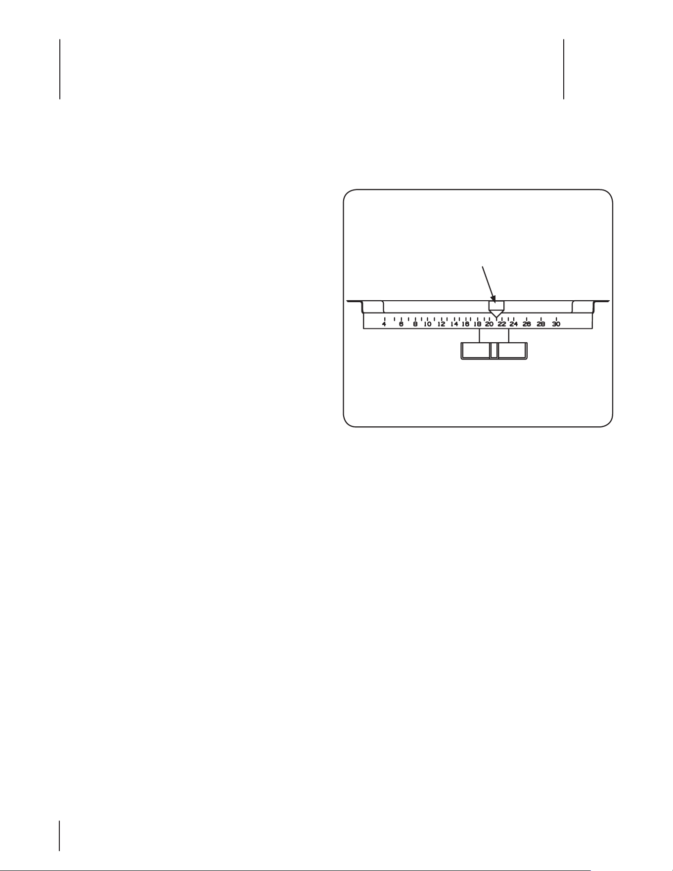
To Achieve the Correct Product Application Rate:
The approximate spreader settings printed on any 1.
product label should only be used as the initial setting for
calibration. Set the rate control arm at this approximate
setting. See Fig. 6-1.
Using the collection boxes or pans, make a single pass 2.
over them to determine the effective pattern width. The
effective pattern width is twice (2x) the distance to the
point where the rate drops to one-half the average rate at
the center.
Note: If the product in the vials from the center boxes
averages two inches in depth, count out to the vial which
has one inch of product. If this is the fifth vial from the
center and the boxes were on one-foot centers, the
effective pattern width is ten feet (2 x 5 ft.).
Knowing the effective pattern width (ten feet), measure 3.
out a lineal distance to equal 1,000 sq. ft. (10 ft. x 100 ft. =
1,000 sq. ft.).
Weigh 20 lbs. of product and place it in the spreader 4.
hopper.
Spread it over the distance necessary to equal 1,000 sq. ft. 5.
(100 ft.).
Weigh the product left in the hopper and subtract this 6.
amount from the amount with which you started. The
result is the application rate for this product in pounds
per 1,000 sq. ft. that your spreader is currently adjusted to
disperse.
Adjust the rate control arm up or down as needed and 7.
repeat this procedure until the correct application rate is
achieved.
Rate Control Arm
Figure 6-1
15se c t i O n 6 — Ma i n t e n a n c e & ad j u s t M e n t s
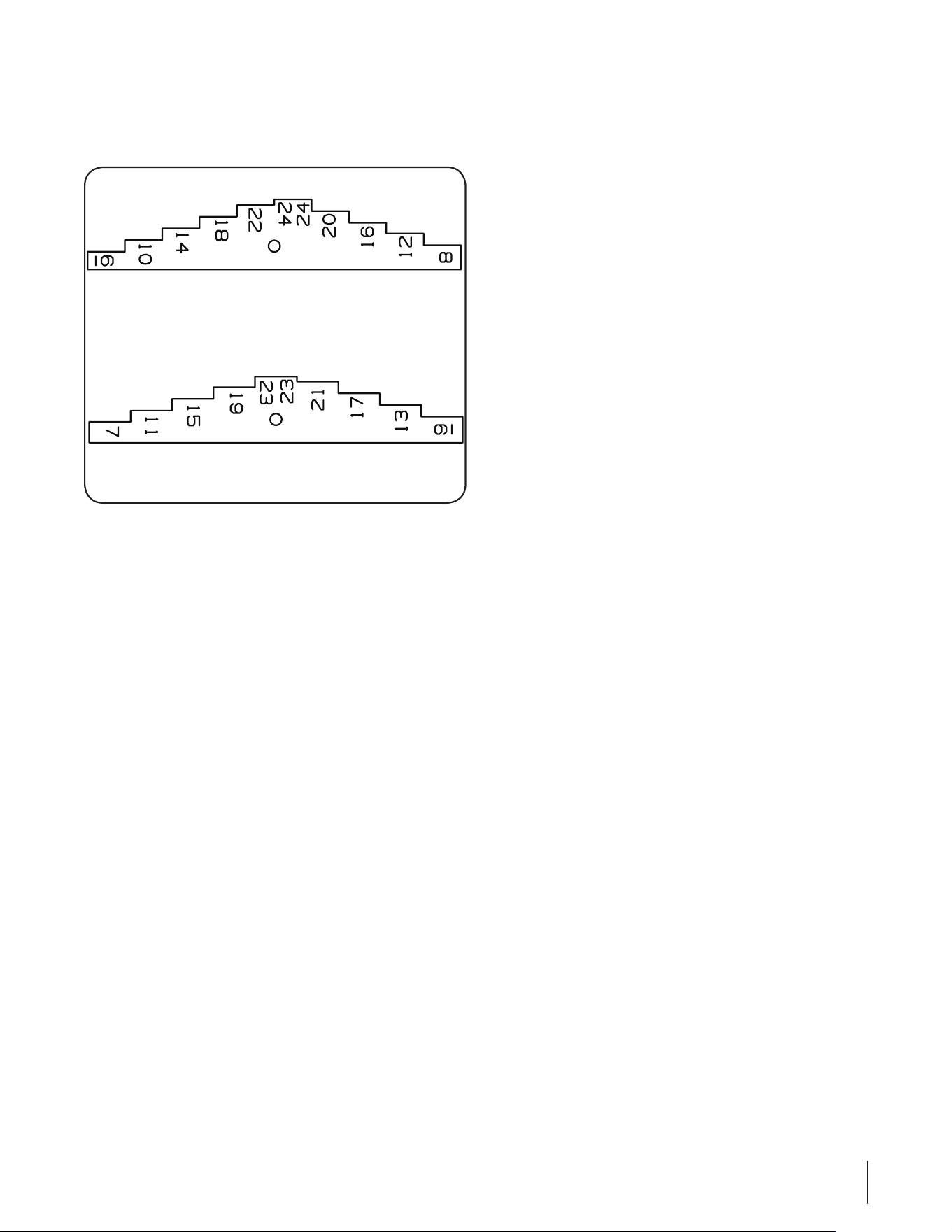
To Use the Calibration Gauges:
The Calibration Gauges provide a series of “steps”, numbered in
1⁄32” increments, that will allow you to “fine-tune” the spreader.
Refer to Fig. 6-2.
Once you have calibrated your rotary spreader for the 1.
product chosen, open the operating lever and insert the
calibration gauges until you determine which step fits
tightly into one of the open holes in the hopper bottom.
Record that step number for future reference when using 2.
that product. You may choose to set other rotary spreaders
for application of the same product by adjusting the shut
off plate to that calibration gauge step. This will provide
consistent settings for all of your spreaders.
To re-calibrate your rotary spreader after a period of use, 3.
adjust the rate control arm to the “24” position.
Open the operating lever and insert the even-numbered 4.
Calibration Gauge into one of the open holes in the hopper
bottom.
Close the operating lever and let the shut off plate on the 5.
underside of the hopper make contact with the number 10
step on the Calibration Gauge.
Move the rate control arm back toward the “6” position 6.
until the bottom of the arm makes contact with the shut off
plate. If your spreader is properly adjusted, the top of the
rate control arm should be at setting “10”.
To correct variances, remove the rate control arm, place the 7.
bottom of the arm (up to the bolt hole) in a vise, and bend
either to the right or the left.
Calibration Gauge (Even)
Calibration Gauge (Odd)
Figure 6-2
Maintenance
Empty the spreader after each use. Wash the spreader 1.
thoroughly and allow it to dry. Keep the impeller clean.
Lubricate all moving parts. Apply grease to the five grease 2.
fittings; two in the axle supports, two in the gear support
and one in the idler wheel (if the idler wheel has a steel
hub).

Troubleshooting
8
16
Problem Cause Remedy
Product not discharging Discharge holes clogged1.
Product clumped together2.
Clear discharge holes1.
Break up clumps2.
Product discharging while
On/Off Lever is in the “OFF”
position.
On/Off Lever needs adjusted1. Adjust lever, see Maintenance & Adjustments 1.
section
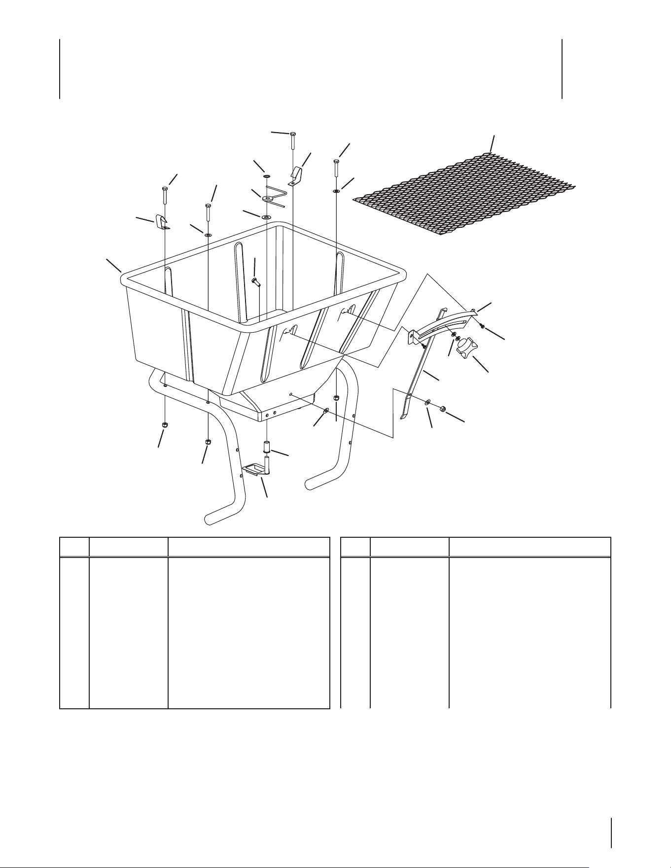
Illustrated Parts List
8
17
Ref.
Part Number Description
1 00005530 Flat Washer, .406 x .812 x .062
2 00018628 Nylon Washer, 1⁄4
3 00030322 Agitator Cam Assembly
4 00031167 Hex Screw, 1⁄4-20 x 1.50
5 00031168 Hex Screw, 1⁄4-20 x .75
6 00060027 Agitator Bearing Shaft
7 00060033 Flat Washer, 1⁄4
8 00060036 Nut, 1⁄4-20
9 00060043 Control Rate Knob
4
4
11
11
4
1
12
13
7
4
7
8
7
10
2
9
14
15
6
3
8
8
7
8
17
5
16
Ref.
Part Number Description
10 00060044 Rate Control Arm
11 00060046 Screen Clip
12 00060049 Agitator Arm Assembly
13 00060050 Retainer Spring Clip, 3⁄8
14 01005631 Hex Washer Screw, #8 x 3⁄8
15 01006772 Numeric Rate Plate
16 01010116 Screen, 80-pound
17 02004176 80-pound Hopper Assembly
18 se c t i O n 8 — il l u s t r a t e d pa r t s li s t
10
10
31
35
23
1
37
24
32
25
16
16
28
29
27
Shown For Reference Only
33
34
3
34
17
3
25
2
20
36
25
25
20
3
20
13
5
9
22
26
4
7
15
21
11
14
12
19
8
30
8
6
18
19
39
38
40
18
30

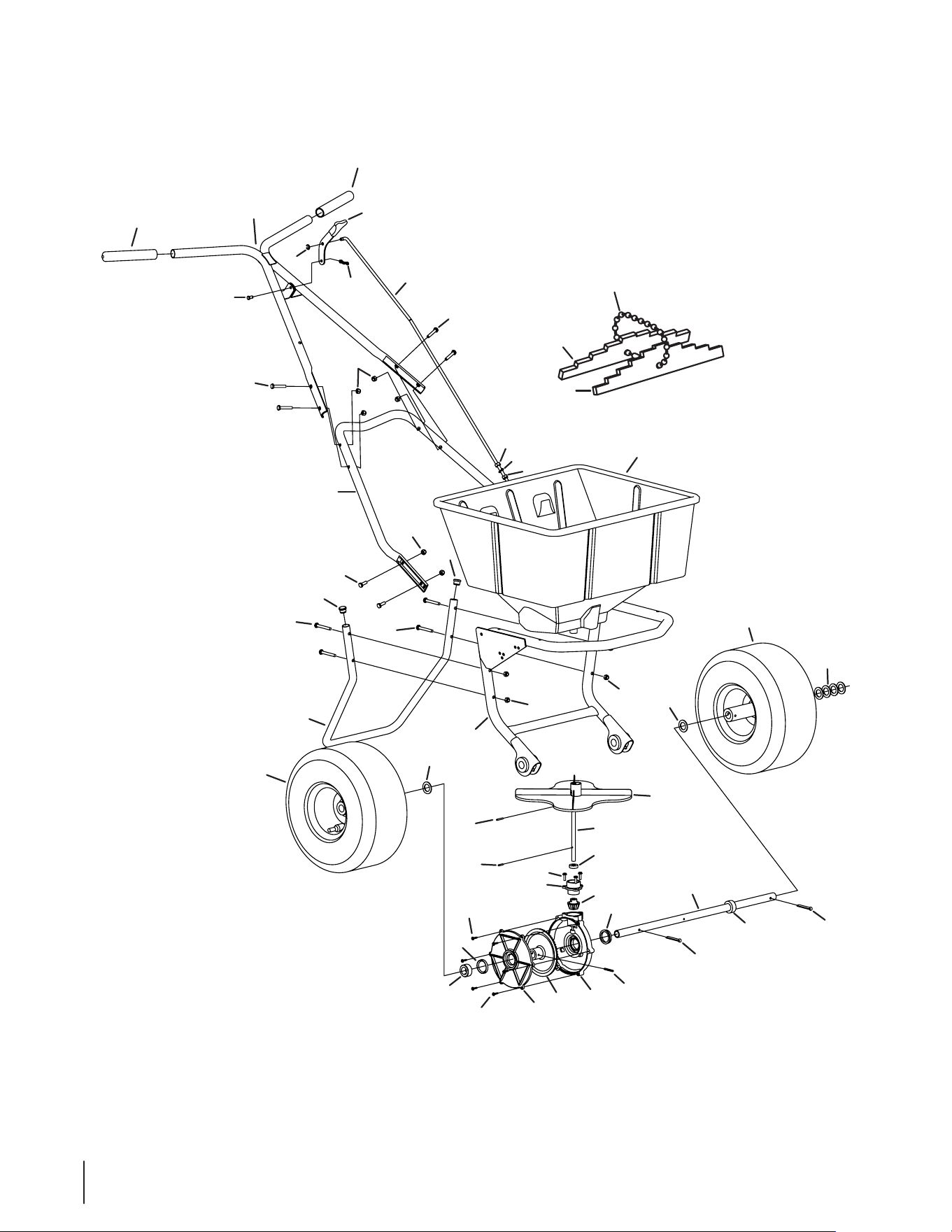
19se c t i O n 8 — il l u s t r a t e d pa r t s li s t
Ref.
Part Number Description
1 00010171 Retainer Clip
2 00018901 Wheel Drive Assembly, 13 x 5.00 x 6
3 00020913 Plastic Plug
4 00030317 Impeller
5 00030382 Impeller Shaft
6 00030383 Axle
7 00030384 Oil Seal
8 00030385 Gearset Seal
9 00030415 Tap Screw, #10
10 00030446 Handle Grip
11 00030591 Gearset Housing
12 00030592 Gearset Cover
13 00030593 Gearset Cap
14 00030594 Bevel Gear
15 00030595 Pinion Gear
16 00031167 Hex Screw, 1⁄4-20 x 1.50
17 00031168 Hex Screw, 1⁄4-20 x .75
18 00060012 Cotter Pin, 3⁄16 x 1-3⁄4
19 00060014 Axle Collar
20 00060017 Flat Washer, .06 x .776 x 1.25
21 00060019 Roller Pin, 5⁄32 x 1-1
22 00060022 Roller Pin, 1⁄8 x 5⁄8
23 00060031 Clevis Pin, 1⁄4 x 1⁄2
24 00060034 Dual Remote Lever
25 00060036 Nut, 1⁄4-20
26 00060069 Roller Pin, 1⁄8 x 7⁄8
27 00060071 Hex Nut, 5⁄16-18
28 00060072 Nut, 5⁄16-18
29 00060073 Lock Washer, 5⁄16
30 01000129 Hex Washer Screw, 8-18 x 6 x 5⁄8
31 01004875 Handle Assembly
32 01004876 Lower Handle
33 01004878 Support Leg
34 01005552 Hex Screw, 1⁄4-20 x 2.00
35 01006035 Operating Lever Rod
36 01006129 Frame/Bearing Assembly
37 02004552 Bow-Tie Cotter Pin
38 00009742 Calibration Gauge (Odd)
39 00009746 Calibration Gauge (Even)
40 00009941 Gauge Chain

20 se c t i O n 8 — il l u s t r a t e d pa r t s li s t
7
5
3
2
4
11
8
14
11
8
6
12
10
9
1
13
11
8
Ref.
Part Number Description
1 00020492 Slide Lever
2 00060033 Flat Washer, 1⁄4
3 00060036 Nylon Nut, 1⁄4-20
4 00060060 Pivot Lever Assembly
5 00060061 Pivot Lever Rod
6 01004186 Clip Service Spring
7 01004539 Two Hole Plate Weldment
8 01004955 Shut-O Plate Clip
9 01004956 Shut-O Plate Spring
10 01005630 Flat Washer, #8
11 01005631 Hex Washer Screw, #8 x 3⁄8
12 01005632 Hex Washer Screw, #8 x 5⁄8
13 01006825 Shut-O Plate, 80-pound
14 02004552 Bow-Tie Cotter Pin, 72

Attachments & Accessories
9
21
Part Part No.
80-pound Hopper Cover 01001251
Remote Deflector 02004519
Remote 3rd Hole 02004521
Standard Deflector 02004523

Notes
10
22

23se c t i O n 10 — nO t e s

CUB CADET LLC
MANUFACTURER’S LIMITED WARRANTY
FOR COMMERCIAL LAWN APPLICATION EQUIPMENT
Cub Cadet LLC, P.O. BOX 361131 CLEVELAND, OHIO 44136-0019, Phone: 1-877-282-8684
MTD Products Limited, Kitchener, ON N2G 4J1, Phone: 1-800-668-1238
GDOC-100208 REV. A
IMPORTANT: To obtain warranty coverage owner must present an
original proof of purchase and applicable maintenance records to the
servicing dealer. Please see the operator’s manual for information on
required maintenance and service intervals.
The limited warranty set forth below is given by Cub Cadet LLC with
respect to new merchandise purchased or leased and used in the
United States and/or its territories and possessions, and by MTD
Products Limited with respect to new merchandise purchased or
leased and used in Canada and/or its territories and possessions
(either entity respectively, “Cub Cadet”).
Cub Cadet warrants this product (excluding its Normal Wear Parts,
Batteries and Attachments as described below) against defects in
material and workmanship for a period of one (1) year commencing
on the date of original retail purchase or lease and will, at its option,
repair or replace, free of charge, any part found to be defective in
materials or workmanship.
Normal Wear Parts are warranted to be free from defects in material
and workmanship for a period of thirty (30) days or one hundred
(100) operation hours, whichever comes first, commencing on the
date of original retail purchase or lease. Normal wear parts include,
but are not limited to items such as: belts, blades, blade adapters,
grass bags, rider deck wheels, seats, and tires.
Batteries have a one-year prorated limited warranty against defects
in material and workmanship, with 100% replacement during the
first three months. After three months, the battery replacement
credit is based on the months remaining in the twelve (12) month
period dating back to the original date of original sale or lease. Any
replacement battery will be warranted only for the remainder of the
original warranty period.
Attachments — Cub Cadet warrants attachments for this product
against defects in material and workmanship for a period of one (1)
year, commencing on the date of the attachment’s original purchase
or lease. Attachments include, but are not limited to items such as:
grass collectors and mulch kits.
This limited warranty shall only apply if this product has been
operated and maintained in accordance with the Operator’s Manual
furnished with the product, and has not been subject to misuse,
abuse, neglect, accident, improper maintenance, alteration,
vandalism, theft, fire, water, or damage because of other peril or
natural disaster. Damage resulting from the installation or use of any
part, accessory or attachment not approved by Cub Cadet for use
with the product(s) covered by this manual will void your warranty as
to any resulting damage. In addition, Cub Cadet may deny warranty
coverage if the hour meter, or any part thereof, is altered, modified,
disconnected or otherwise tampered with.
HOW TO OBTAIN SERVICE: Warranty service is available, WITH
PROOF OF PURCHASE AND APPLICABLE MAINTENANCE RECORDS,
through your local authorized service dealer. To locate the dealer in
your area:
In the U.S.A.:
Check your Yellow Pages, or contact Cub Cadet LLC at P.O. Box
361131, Cleveland, Ohio 44136-0019, call 1-877-282- 8684
or log on to our website at www.cubcadet.com.
In Canada:
Contact MTD Products Limited, Kitchener, ON N2G 4J1, call 1-800-
668-1238 or log on to our website at www.mtdcanada.com.
Without limiting the foregoing, this limited warranty does not provide
coverage in the following cases:
a. Routine maintenance items such as lubricants, filters, blade
sharpening, tune-ups, brake adjustments, clutch adjustments,
deck adjustments, and normal deterioration of the exterior finish
due to use or exposure.
b. Service completed by someone other than an authorized service
dealer.
c. Cub Cadet does not extend any warranty for products sold or
exported outside of the United States and/or Canada, and their
respective possessions and territories, except those sold through
Cub Cadet’s authorized channels of export distribution.
d. Replacement parts and\or accessories that are not genuine Cub
Cadet parts.
e. Transportation charges and service calls.
There are no implied warranties, including without limitation any
implied warranty of merchantability or fitness for a particular
purpose. No warranties shall apply after the applicable period
of express written warranty above. No other express warranties
beyond those mentioned above, given by any person or entity,
including a dealer or retailer, with respect to any product, shall
bind Cub Cadet. The exclusive remedy is repair or replacement of
the product as set forth above. The terms of this warranty provide
the sole and exclusive remedy arising from the sale and/or lease
of the products covered hereby. Cub Cadet shall not be liable for
any incidental or consequential loss or damage including, without
limitation, expenses incurred for substitute or replacement lawn
care services or for rental expenses to temporarily replace a
warranted product.
Some jurisdictions do not allow the exclusion or limitation of
incidental or consequential damages, or limitations on how long an
implied warranty lasts, so the above exclusions or limitations may not
apply to you.
In no event shall recovery of any kind be greater than the amount of
the purchase price of the product sold. Alteration of safety features of
the product shall void this warranty. You assume the risk and liability
for loss, damage, or injury to you and your property and/or to others
and their property arising out of the misuse or inability to use the
product.
This limited warranty shall not extend to anyone other than the
original purchaser or to the person for whom it was purchased as a
gift.
HOW LOCAL LAWS RELATE TO THIS WARRANTY: This limited
warranty gives you specific legal rights, and you may also have other
rights that vary in different jurisdictions.

