CUB CADET LLC, P.O. BOX 361131 CLEVELAND, OHIO 44136-0019
Printed In USA
OperatOr’s Manual
Safe Operation Practices • Set-Up • Controls • Operation • Maintenance • Troubleshooting • Specications
WARNING
READ AND FOLLOW ALL SAFETY RULES AND INSTRUCTIONS IN THIS MANUAL
BEFORE ATTEMPTING TO OPERATE THIS MACHINE.
FAILURE TO COMPLY WITH THESE INSTRUCTIONS MAY RESULT IN PERSONAL INJURY.
Form No. 769-07267
(July 26, 2011)
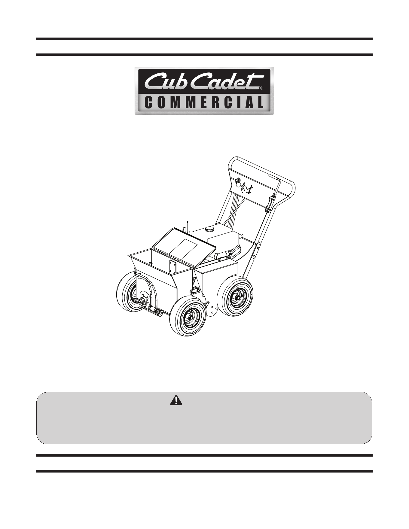
Hydraulic Renovator

To The Owner
1
2
Safe Operation Practices ........................................ 3
Set-up ....................................................................... 8
Controls .................................................................... 9
Operation ................................................................ 11
Maintenance ...........................................................13
Specications ..........................................................16
Troubleshooting .....................................................17
Warranties ..............................................................18
Table of Contents
Customer Support
If you have difficulty assembling this product or have any questions regarding the controls, operation, or maintenance of
this machine, you can seek help from the experts. Choose from the options below:
◊ Visit us on the web at www.cubcadet.com
◊ Locate your nearest Cub Cadet Dealer at (877) 282-8684
◊ Write us at Cub Cadet LLC • P.O. Box 361131 • Cleveland, OH • 44136-0019
Thank you for purchasing a Hydraulic Renovator manufactured
by Cub Cadet LLC. The Renovator is designed to provide
professional landscapers, commercial lawn service companies,
professional turf managers and golf course superintendents
with a reliable and economical slicer, seeder and dethatcher. The
Renovator is an excellent machine for applying seed to new or
previously seeded turf grass areas. However, due to the many
variables involved, including soil conditions, moisture, time of
seeding, fertilization, weather, condition and age of grass seed,
we are unable to guarantee results. It was carefully engineered
to provide excellent performance when properly operated and
maintained.
Please read this entire manual prior to operating the equipment.
It instructs you how to safely and easily set up, operate and
maintain your machine. Please be sure that you, and any other
persons who will operate the machine, carefully follow the
recommended safety practices at all times. Failure to do so could
result in personal injury or property damage.
All information in this manual is relative to the most recent
product information available at the time of printing. Review
this manual frequently to familiarize yourself with the machine,
its features and operation. Please be aware that this Operator’s
Manual may cover a range of product specifications for various
models. Characteristics and features discussed and/or illustrated
in this manual may not be applicable to all models. Cub Cadet
LLC reserves the right to change product specifications, designs
and equipment without notice and without incurring obligation.
If you have any problems or questions concerning the machine,
phone your local Cub Cadet dealer or contact us directly. Cub
Cadet’s Dealer Locator telephone number, web site address and
mailing address can be found on this page. We want to ensure
your complete satisfaction at all times.
Throughout this manual, all references to right and left side of the
machine are observed from the operating position.
The engine manufacturer is responsible for all engine-related
issues with regards to performance, power-rating, specifications,
warranty and service. Please refer to the engine manufacturer’s
Owner’s/Operator’s Manual, packed separately with your
machine, for more information.
Thank You
Record Product Information
Before setting up and operating your new equipment, please
locate the model plate on the equipment and record the
information in the provided area to the right. You can locate the
model plate by standing at the operator’s position and looking
at the back of the unit. This information will be necessary, should
you seek technical support via our web site or with your local
Cub Cadet dealer.
Model NuMber
Serial NuMber
Important Safe Operation Practices
2
3
General Operation
1. Read this Operator’s Manual before starting the Renovator.
Study the controls and learn the proper sequence of
operation.
2. Do not allow anyone to operate or maintain this machine
who has not read the manual. Never permit children to
operate this machine.
3. Always have your feet and hands clear of the power deck
when starting the engine.
4. Do not remove the seeder safety switch. If this switch is
damaged or does not function, repair or replace it before
operating the Renovator.
5. Do not remove any shields, guards, decals or safety devices.
If a shield, guard, decal or safety device is damaged or
does not function, repair or replace it before operating the
Renovator.
6. Always wear safety glasses, long pants and safety shoes
when operating or maintaining this machine. Do not wear
loose-fitting clothing.
7. Never run the engine indoors without adequate
ventilation. Exhaust fumes are deadly.
8. To avoid serious burns, do not touch the engine, muffler or
hydraulic components while the engine is running or until
everything has cooled after the engine has been shut off.
9. Keep adults, children and pets away from the area to be
renovated.
10. Always remove debris and other objects from the area to
be renovated.
11. Watch out for rocks, small tree stumps, sprinkler heads,
water shutoff plates, etc.
12. When starting the engine, always have the hydraulic
traction control lever in neutral and never have the slicer
safety clutch engaged.
13. Operate the machine in a straight line to avoid damage to
the slicer blades.
14. Always have proper footing on slopes and hillsides and
never operate when conditions are slippery.
15. Always keep both hands on the handle.
16. Be careful when crossing roadways. Always release the
slicer safety clutch and place the machine in the transport
position.
WARNING: This symbol points out important safety instructions which, if not followed,
could endanger the personal safety and/or property of yourself and others. Read and follow
all instructions in this manual before attempting to operate this machine. Failure to comply
with these instructions may result in personal injury.
When you see this symbol. HEED ITS WARNING!
DANGER: This machine was built to be operated according to the safe operation practices in
this manual. As with any type of power equipment, carelessness or error on the part of the
operator can result in serious injury. This machine is capable of amputating fingers, hands,
toes and feet and throwing objects. Failure to observe the following safety instructions could
result in serious injury or death.
CALIFORNIA PROPOSITION 65
WARNING: Engine Exhaust, some of its constituents, and certain vehicle components
contain or emit chemicals known to State of California to cause cancer and birth defects
or other reproductive harm.
WARNING: Battery posts, terminals, and related accessories contain lead and lead
compounds, chemicals known to the State of California to cause cancer and reproductive
harm. Wash hands after handling.

4 Section 2 — important Safe operation practiceS
17. When leaving the Renovator unattended, shift the
hydraulic traction control lever into neutral, shut off the
engine, shut the fuel shutoff valve and disconnect the
spark plug wire.
18. Always park the Renovator and start the engine on a level
surface with the hydraulic traction control lever in neutral.
19. If you hit a solid object while slicing, release the slicer
safety clutch, shift the hydraulic traction control lever into
neutral and shut off the engine. Disconnect the spark plug
wire and inspect the slicer reel for damage. Repair any
damage and make sure the blades are in good condition
and the blade bolts are tight before restarting the engine.
20. Always disconnect the spark plug wire to prevent the
engine from accidentally starting before performing any
maintenance on this machine.
21. Keep the Renovator and especially the engine, pump and
belt area clean and free of grease, grass and leaves to
reduce the chance of fire and to permit proper cooling.
Slope Operation
Slopes are a major factor related to slip and fall accidents, which
can result in severe injury. Operation on slopes requires extra
caution. If you feel uneasy on a slope, do not operate on it. For
your safety, use the slope gauge included as part of this manual
to measure slopes before operating this machine on a sloped or
hilly area. If the slope is greater than 15 degrees, do not operate
on it.
Do:
1. Move across the face of slopes; never up and down. Exercise
extreme caution when changing direction on slopes.
2. Watch for holes, ruts, rocks, hidden objects, or bumps
which can cause you to slip or trip. Tall grass can hide
obstacles.
3. Always be sure of your footing. A slip and fall can cause
serious personal injury.
Do Not:
1. Do not operate near drop-offs, ditches or embankments,
you could lose your footing or balance.
2. Do not operate on slopes greater than 15 degrees as shown
on the slope gauge.
3. Do not operate on wet grass. Unstable footing could cause
slipping.
Service
Safe Handling Of Gasoline:
1. To avoid personal injury or property damage use extreme
care in handling gasoline. Gasoline is extremely flammable
and the vapors are explosive. Serious personal injury can
occur when gasoline is spilled on yourself or your clothes,
which can ignite. Wash your skin and change clothes
immediately.
2. Use only an approved gasoline container.
3. Never fill containers inside a vehicle or on a truck or trailer
bed with a plastic liner. Always place containers on the
ground away from your vehicle before filling.
4. Remove gas-powered equipment from the truck or
trailer and refuel it on the ground. If this is not possible,
then refuel such equipment on a trailer with a portable
container, rather than from a gasoline dispenser nozzle.
5. Keep the nozzle in contact with the rim of the fuel tank or
container opening at all times until fueling is complete. Do
not use a nozzle lock-open device.
6. Extinguish all cigarettes, cigars, pipes and other sources
of ignition.
7. Never fuel machine indoors because flammable vapors will
accumulate in the area.
8. Never remove gas cap or add fuel while engine is hot or
running. Allow engine to cool at least two minutes before
refueling.
9. Never over fill fuel tank. Fill tank to no more than 1 inch
below bottom of filler neck to provide for fuel expansion.
10. Replace gasoline cap and tighten securely.
11. If gasoline is spilled, wipe it off the engine and equipment.
Move machine to another area. Wait 5 minutes before
starting engine.
12. Never store the machine or fuel container near an open
flame, spark or pilot light as on a water heater, space
heater, furnace, clothes dryer or other gas appliances.
13. To reduce fire hazard, keep machine free of grass, leaves,
or other debris build-up. Clean up oil or fuel spillage and
remove any fuel soaked debris.
14. Allow machine to cool at least 5 minutes before storing.

5Section 2 — important Safe operation practiceS
General Service:
1. Never run an engine indoors or in a poorly ventilated area.
Engine exhaust contains carbon monoxide, an odorless
and deadly gas.
2. Before cleaning, repairing, or inspecting, make certain all
moving parts have stopped. Disconnect the spark plug
wire and ground against the engine to prevent unintended
starting.
3. Check the blades and engine mounting bolts at frequent
intervals for proper tightness. Also, visually inspect blades
for damage (e.g., bent, cracked, worn) Replace blades with
the original equipment manufacture’s (O.E.M.) blade only,
listed in this manual. “Use of parts which do not meet the
original equipment specifications may lead to improper
performance and compromise safety!”
4. Renovator blades are sharp and can cut. Wrap the blades or
wear gloves, and use extra caution when servicing them.
5. Keep all nuts, bolts, and screws tight to be sure the
equipment is in safe working condition.
6. Never tamper with safety devices. Check their proper
operation regularly.
7. After striking a foreign object, stop the engine, disconnect
the spark plug wire and ground against the engine.
Thoroughly inspect the unit for any damage. Repair the
damage before starting and operating the renovator.
8. Never attempt to make a wheel or cutting height
adjustment while the engine is running.
9. Guards and shields are subject to wear and damage which
could expose moving parts or allow objects to be thrown.
For safety protection, frequently check components
and replace immediately with original equipment
manufacturer’s (O.E.M.) parts only, listed in this manual.
“Use of parts which do not meet the original equipment
specifications may lead to improper performance and
compromise safety!”
10. Do not change the engine’s governor setting or over-speed
the engine. The governor controls the maximum safe
operating speed of the engine.
11. Check fuel line, tank, cap, and fittings frequently for cracks
or leaks. Replace if necessary.
12. Do not crank engine with spark plug removed.
13. Maintain or replace safety and instruction labels, as
necessary.
14. Observe proper disposal laws and regulations. Improper
disposal of fluids and materials can harm the environment.
Do not modify engine
To avoid serious injury or death, do not modify engine in any
way. Tampering with the governor setting can lead to a runaway
engine and cause it to operate at unsafe speeds. Never tamper
with factory setting of engine governor.
Notice Regarding Emissions
Engines which are certified to comply with California and federal
EPA emission regulations for SORE (Small Off Road Equipment)
are certified to operate on regular unleaded gasoline, and
may include the following emission control systems: Engine
Modification (EM), Oxidizing Catalyst (OC), Secondary Air
Injection (SAI) and Three Way Catalyst (TWC) if so equipped.
Spark Arrestor
WARNING: This machine is equipped with an
internal combustion engine and should not be used
on or near any unimproved forest-covered, brush
covered or grass-covered land unless the engine’s
exhaust system is equipped with a spark arrestor
meeting applicable local or state laws (if any).
If a spark arrestor is used, it should be maintained in effective
working order by the operator. In the State of California the
above is required by law (Section 4442 of the California Public
Resources Code). Other states may have similar laws. Federal laws
apply on federal lands.
A spark arrestor for the muffler is available through your
nearest engine authorized service dealer or contact the service
department, P.O. Box 361131 Cleveland, Ohio 44136-0019.

6 Section 2 — important Safe operation practiceS
Safety Symbols
This page depicts and describes safety symbols that may appear on this product. Read, understand, and follow all instructions on the
machine before attempting to assemble and operate.
Symbol Description
READ THE OPERATOR’S MANUAL(S)
Read, understand, and follow all instructions in the manual(s) before attempting to
assemble and operate
DANGER — ROTATING BLADES
To reduce the risk of injury, keep hands and feet away. Do not operate unless discharge cover
or grass catcher is in its proper place. If damaged, replace immediately.
DANGER — BYSTANDERS
Do not mow when children or others are around.
DANGER — HAND/ FOOT CUT
Keep hands and feet away from rotating parts.
DANGER — THROWN DEBRIS
Remove objects that can be thrown by the blade in any direction. Wear safety glasses.
DANGER — SLOPES
Use extra caution on slopes. Do not mow slopes greater than 15°.
WARNING—GASOLINE IS FLAMMABLE
Allow the engine to cool at least two minutes before refueling.
WARNING— CARBON MONOXIDE
Never run an engine indoors or in a poorly ventilated area. Engine exhaust contains carbon
monoxide, an odorless and deadly gas.
WARNING— HOT SURFACE
Engine parts, especially the muffler, become extremely hot during operation. Allow engine
and muffler to cool before touching.
WARNING: Your Responsibility—Restrict the use of this power machine to persons who read, understand and
follow the warnings and instructions in this manual and on the machine.
SAVE THESE INSTRUCTIONS!
7Section 2 — important Safe operation practiceS
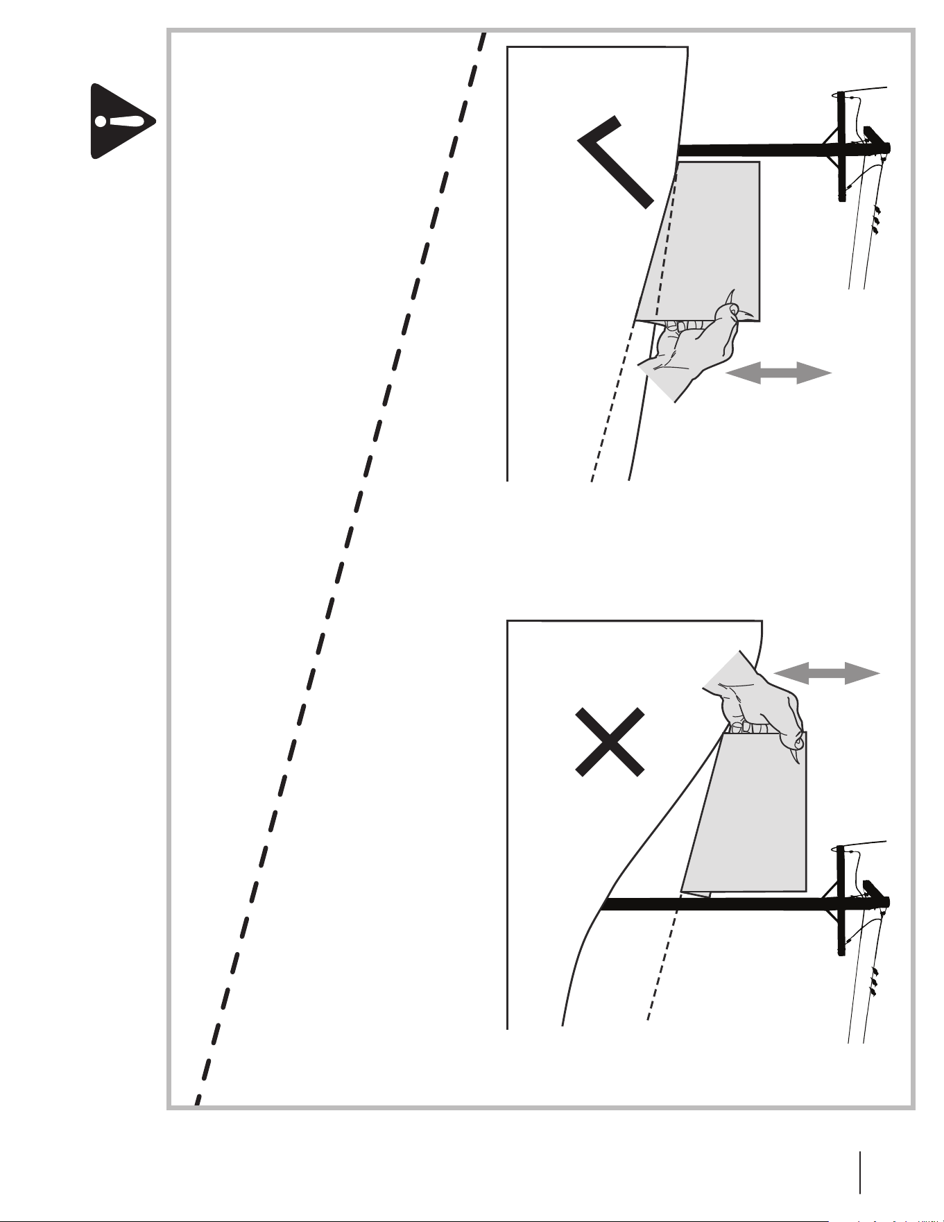
(OK) (TOO STEEP)
USE THIS SLOPE GAUGE TO DETERMINE
IF A SLOPE IS TOO STEEP FOR SAFE OPERATION!
To check the slope, proceed as follows:
1. Remove this page and fold along the dashed line.
2. Locate a vertical object on or behind the slope (e.g. a pole, building, fence, tree, etc.)
3. Align either side of the slope gauge with the object (See Figure 1 and Figure 2 ).
4. Adjust gauge up or down until the left corner touches the slope (See Figure 1 and Figure 2).
5. If there is a gap below the gauge, the slope is too steep for safe operation (See Figure 2 above).
15° dashed line
Slope Gauge
Figure 2Figure 1
15° Slope
15° Slope
WARNING! Slopes are a major factor related to tip-over and roll-over accidents which can result in severe injury or death.
Do not operate machine on slopes in excess of 15 degrees. All slopes require extra caution.
Always mow across the face of slopes, never up and down slopes.

3
8
3
8
Set-Up
Initial Adjustments
WARNING! Before performing any adjustments,
disconnect the spark plug wire to prevent the
engine from accidentally starting.
Tires
1. Check the tire pressure. Proper operating pressure is 20 psi.
NOTE: New tires might be overinflated in order to properly
seat the bead to the rim.
Belt Tension
1. Remove the belt safety cover.
2. Make sure the belts clear the belt guides by 1/8” to 1/4”
inch with operating levers engaged.
The slicer safety clutch should be adjusted so that when the lever
is pulled back and held down against the handle assembly, the
slicer reel drive belt is tight.
First, adjust the slicer clutch control cable where it passes
through the lower handle:
1. Loosen the two adjustment nuts on the cable jacket and
move the jacket down to tighten or up to loosen the
pressure of the idler pulleys on the slicer reel drive belt.
2. Re-tighten the adjustment nuts. If the drive belt is still not
tight when the cable jacket is down as far as it will go, the
engine must be adjusted.
3. The engine must be moved to the rear to tighten the belt
(or forward to loosen the belt):
a. Loosen the pump mounting bolts and move the
pump to the rear.
b. Loosen the engine mounting bolts, move the engine
to adjust the slicer reel drive belt and then tighten
the engine mounting bolts. (The mounting bolts
are threaded into nut bars which will slide with the
pump or the engine.)
c. Move the pump forward to tighten the pump drive
belt. The tension of the pump drive belt should be
adjusted so that a five-pound pull between the
engine pulley and the pump pulley deflects the belt
about 3/16 inch.
d. Tighten the pump mounting bolts.
e. Readjust the position of the control cable in the
lower handle.
3. Replace the belt safety cover.
Traction Drive Chain Tension
1. Raise the rear end of the power deck off the ground.
2. Press in on the traction drive chain between the drive
sprocket on the hydraulic motor and the driven sprocket on
the differential. The chain should deflect 3/16 inch.
3. To adjust the tension in this chain, the hydraulic motor
must be moved. Loosen the four mounting bolts which
hold the motor to its mounting bracket and pivot the
motor to the proper position and tighten the four
mounting bolts.
4. While the traction drive chain is exposed, oil it lightly with
clean engine oil.
5. Lower the rear end of the Renovator back to the ground.
Gas and Oil Fill-up
WARNING! Use extreme care when handling
gasoline. Gasoline is extremely flammable and the
vapors are explosive. Never fuel machine indoors or
while the engine is hot or running. Extinguish
cigarettes, cigars, pipes, and other sources of ignition.
IMPORTANT: Your renovator is shipped with motor oil in
the engine. However, you MUST check the oil level before
operating. Be careful not to overfill.
1. Check the hydraulic oil level. When filling the tank, stop
when the oil reaches one inch from the top. This space
must be left for expansion. Use 1OW-40 engine oil.
2. Check the engine oil level. Fill to the proper level with
10W40 engine oil rated for service SE or SF.
3. Before moving the renovator, set the slicer depth adjusting
lever so that the slicer reel is in the fully raised position.
Then, shift the hydraulic traction control lever to forward if
you wish to push the machine forward or hold it in reverse
if you wish to pull the unit to the rear.
4. Move the machine outdoors. Check the engine gasoline
level. When filling the tank, stop when the gasoline
reaches one inch from the top. This space must be left for
expansion. Use fresh, clean, unleaded, regular gasoline.
4. Lubricate all fittings listed in the maintenance section.
5. Check that all nuts, bolts, and screws are tight.
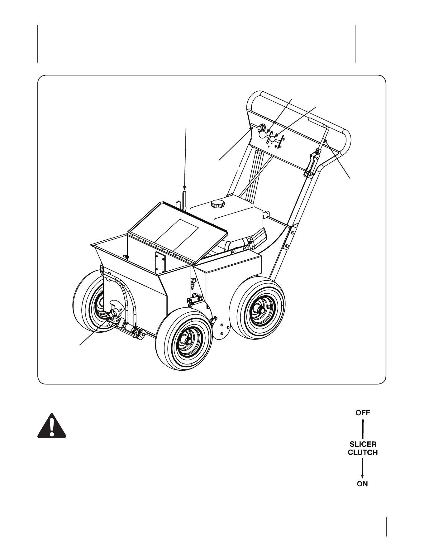
Controls & Features
4
9
Renovator controls and features are illustrated in Fig 4-1 and
described on the following pages.
WARNING! Read and follow all safety rules and
instructions in this manual, including the entire
Operation section, before attempting to operate
this machine. Failure to comply with all safety rules
and instructions may result in personal injury.
Figure 4-1
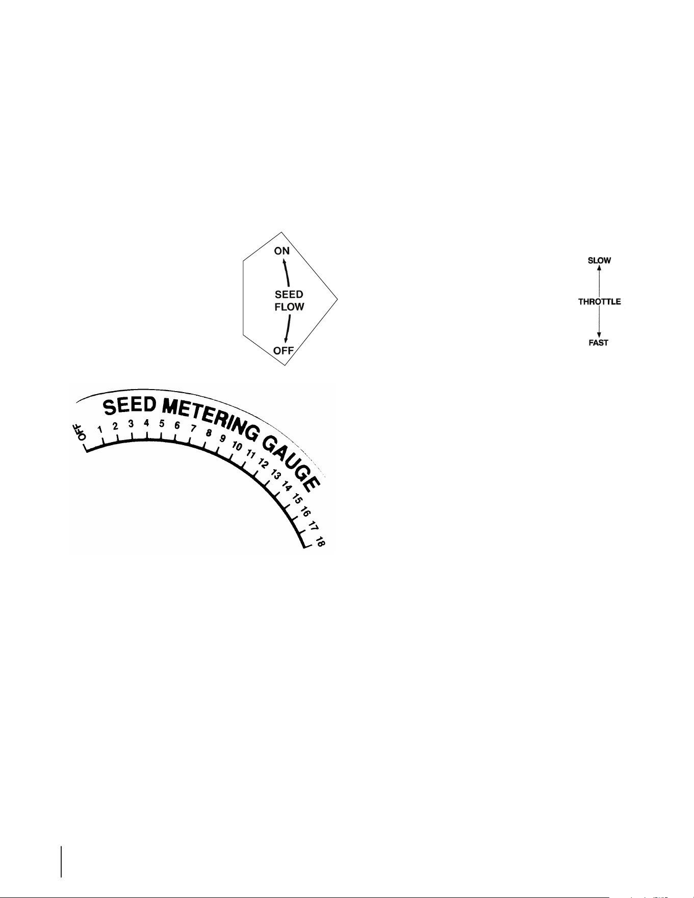
Slicer Safety Clutch
Engine Throttle
Hydraulic Traction
Control Lever
Slicer Depth
Adjusting Lever
Seed Flow Lever
Seed Metering
Gauge
Renovator Controls
Slicer Safety Clutch
The slicer safety clutch is the large “L”-shaped
lever located on the left side of the control
panel, and when pulled back, causes the slicer
reel to rotate. To disengage the slicer clutch,
release the ‘L’ shaped lever. See Fig. 4-1.
10 Section 4 — controlS and FeatureS
Hydraulic Traction Control Lever
The hydraulic traction control lever is located
on the control panel at the top of the handle
assembly and is used to determine the
direction of travel. It can be moved into three
positions — Forward, Neutral and Reverse. This
lever also enables the Renovator to move when
the engine is not running, this lever must be
placed in the forward position to push the Renovator forward or
held in the reverse position to pull the Renovator to the rear.
NOTE: Before starting the engine, this lever must be placed in
the neutral position or the neutral safety switch will not permit
the engine to start.
Seed Flow Lever
The seed flow lever is located on the
right side of the control panel, and when
pushed forward, opens the hydraulic seed
gate to the preset adjustment causing
the seed to start flowing through the
diamond-shaped openings. When the
lever is pulled backward, the seed gate
will close and stop the seed flow.
Seed Metering Gauge
The seed metering gauge is located on the seed hopper at the
front of the machine. The adjustment is made by loosening
the threaded handle and turning the adjustment dial to the
desired setting and then tightening the handle to lock the dial
in position. The settings for common types of seed at various
seeding rates are shown in the Operation section.
Slicer Depth Adjusting Lever
The slicer depth adjusting lever is located on the top of the
power deck on the right side of the machine. To adjust the slicer
depth, grasp the hopper lift handle, release the spring loaded
lock and set depth. Depth adjustment ranges from 0 to 1-1/4” .
NOTE: This adjustment should be made while pushing down on
the Renovator’s handle to take the weight off the front wheels.
FORWARD
NEUTRAL
REVERSE
Engine Controls
On/Off Switch
The on/off switch is located on the front, right side of the engine.
When pushed to the “On” position, the engine can be started.
Fuel Shut-Off Valve
The fuel shut-off valve is located on the rear, right side of the
engine. Moving it to the “On” position allows fuel to flow to the
engine.
Choke Control
The choke control is located on the right side of the engine over
the Fuel Shutoff Valve. Activating the choke control closes the
choke plate on the carburetor and aids in starting the engine.
Throttle Control
The engine throttle is located on the control panel
at the top of the handle assembly and is used to
adjust the engine speed. Move the throttle lever
from the front to the rear to increase the engine
speed from slow to fast.
Recoil Starter
The recoil starter is located on the right side of the engine and is
used to start the engine.
Oil Protection System
This system is designed to prevent engine damage caused by an
insufficient amount of oil in the crankcase. Before the oil level
can fall below a safe limit, the system will automatically shut
down the engine while the engine switch remains in the “On”
position. If this system shuts down the engine, the oil protection
lamp will flash when you pull on the recoil starter but the engine
will not start. If this occurs, check to ensure that the engine is not
leaking and then add engine oil.

Operation
5
11
Using the Renovator
1. Slowly move the hydraulic traction control lever in the
“Forward” direction and the renovator will start to move
forward.
2. Open the seed flow lever by pushing it forward. Use the
hydraulic traction control lever to adjust the forward speed.
3. Push down on the handle to lift the front wheels off the
ground and pull the slicer safety clutch down with your left
hand and hold it against the handle and the slicer reel will
start to rotate.
4. Lower the front wheels and ease the slicer reel into the
ground.
5. Operate the renovator in a straight line. Before you have
reached the end of the first pass, use the hydraulic traction
control lever to slow your rate of travel, close the seed flow
lever and press down on the handle to lift the rotating
slicer reel out of the ground.
NOTE: The slicer reel will not stop rotating unless you
release the slicer safety clutch with your left hand.
6. Turn the renovator around 180 degrees and line up the unit
for a proper overlap.
7. Lower the unit down, easing the slicer reel back into the
ground.
8. Open the seed flow lever and start the second pass,
resuming normal operating speed.
NOTE: For best results, renovate each area in two
directions, 90 degrees apart, at 1/2 the total seeding rate.
IMPORTANT: When renovating an area surrounded by
walkways or driveways, make at least two complete passes
around the perimeter. This will provide enough room to
make turns at the end of each pass without running the
slicer blades into the concrete or asphalt.
9. Practice operating the Renovator for at least one-half hour
and then close the seed flow lever, release the slicer safety
clutch and move the hydraulic traction control lever to
“Neutral”.
10. Set the slicer depth adjusting lever to the transport
position, move the hydraulic traction control lever in the
“Forward” direction and return the machine to the shop.
11. After the first full day of use, all bolts, nuts and screws
should be rechecked for proper tightness and the slicer
safety clutch and the pump drive belt should be rechecked
for proper tension.
WARNING: Make certain you thoroughly
understand all of the safety precautions before you
attempt to operate this machine.
IMPORTANT: Your renovator is shipped with motor oil in the
engine. However, you MUST check the oil level before operating.
Be careful not to overfill. Refer to the Engine Operator’s Manual
included with your unit for complete Gasoline and Oil fill-up
instructions.
Starting the Engine
1. Move the machine to a “test area” where you can operate it
for about a half an hour without being disturbed.
2. Set the slicing/dethatching depth using the slicer depth
adjustment lever. (The blades should just graze the ground
for dethatching and should slice the ground for seeding.)
NOTE: In actual operation, you would perform the
following step. For practice, however, it is not necessary to
load the seed hopper.
3. Set the seed flow adjustment dial at the desired seed flow
rate. The settings for common types of seed at various
seeding rates are shown in the table on page 6. Load the
seed hopper.
4. Do not let anyone touch the slicer safety clutch.
5. Shift the hydraulic traction control lever to neutral.
6. Connect the spark plug wire.
7. Open the fuel shutoff valve.
8. Turn the engine On/Off switch to ON.
9. Place the engine choke control in the CHOKE position.
10. Move the engine throttle control halfway between the
SLOW and FAST position.
11. Grasp the starter grip and pull slowly until the starter
engages and then pull the cord rapidly to overcome
compression, prevent kickback and start the engine. Allow
the cord to recoil slowly. Repeat if necessary with the choke
opened slightly.
12. Push the engine choke to the half open position and allow
the engine to warm up.
13. Once the engine warms up, open the choke all the way and
move the throttle lever to fast.
Stopping the Engine
1. Move the hydraulic traction control lever to NEUTRAL and
push the throttle lever to SLOW.
2. Turn the engine switch to OFF.
3. Close the fuel shutoff valve, and disconnect the spark plug
wire to prevent unintended starting.
12 Section 5 — operation
Slope Operation
Refer to the SLOPE GAUGE in the Safe Operation Practices section
of this manual to help determine slopes where you may operate
the renovator safely.
WARNING: Do not operate on inclines with a slope
in excess of 15 degrees (a rise of approximately 2-1/2
feet every 10 feet). The renovator could overturn
and cause serious injury.
DO:
• Go across slopes, not up and down.
• Remove obstacles such as rocks, limbs, etc.
• Watch for holes, ruts or bumps. Uneven terrain could
overturn the machine. Tall grass can hide obstacles.
• Use slow speed. Choose a low enough speed so that you
will not have to stop while on the slope.
• Keep all movement on the slopes slow and gradual. Do not
make sudden changes in speed or direction.
• Avoid starting or stopping on a slope. If the tires lose
traction, disengage renovator and proceed slowly straight
down the slope.
DO NOT:
• Do not turn on slopes unless necessary; then, turn slowly
and use extra care.
• Do not operate near drop-offs, ditches or embankments.
The unit could suddenly turn over if a wheel is over the
edge of a cliff or ditch, or if an edge caves in.
• Do not operate on wet grass. Reduced traction could
cause sliding.
Seed Flow Settings
The proper seed drop rate has been determined to be about
15 seeds per square inch. Since the size and weight of different
grass seeds varies greatly (see the list in the next column), a
calibration study was performed on the Renovator to determine
the proper flow setting for various seeds. The results are listed in
the table below.
Tall Fescue Approximately 220,000 seeds/lb.
Ryegrass (Perennial) Approximately 250,000 seeds/lb.
Fine Fescue Approximately 550,000 seeds/lb.
Bluegrass Approximately 1,000,000 seeds/lb.
Bermudagrass (Hulled) Approximately 1,900,000 seeds/lb.
Bentgrass Approximately 6,000,000 seeds/lb.
APPROXIMATE SEED FLOW SETTINGS TO ACHIEVE 15 SEEDS
PER SQUARE INCH AT THE FORWARD OPERATING SPEED
SEED TYPE RENOVATOR SETTING APPROXIMATE
SEEDING RATE
PER 1000 SQ.FT.
Ryegrass (Perennial) 6.0 5.0 lb.
8.0 7.0 lb.
15.0 20.0 lb.
Tall Fescue 10.0 8.0 lb.
Creeping Red, Chewings and Hard Fescue 6.0 4.0 lb.
Kentucky Bluegrass 1.0 1.0 lb.
2.0 2.0 lb.
Bentgrass 0.5 0.5 lb.
Bermudagrass (Hulled) 1.0 1.0 lb.

Maintenance & Adjustments
6
13
Maintenance Schedule
After
Each use
Every
25 Hours
Every
100 Hours
Every
200 Hours
Prior
to Storing
Clean the machine and allow to dry
P P
Check Engine Oil Level
P
Check Hydraulic Oil Level
P
Check Air Filter for Dirty, Loose or Damaged Parts
P
Clean and Re-oil Air Filter’s Elements
P
Check the fuel level
P
Clean the cooling-air intake
P
Check Air Cleaner
P
Check slicer blades and mounting bolt tightness
P
Lube Points Listed on previous page
P P
Lube Points Listed on previous page
P P
Check condition and tension of transaxle belt
P
Replace Air Filter Element
P
Change Engine Oil and Replace Oil Filter
P P
Check all nuts, bolts and screws are tight
P P
Replace Spark Plug
P
Check Spark Plug Condition & Gap
P
General Purpose Lubrication: Use any NLGI grade 2 multi-purpose grease. Shell Albida EP2 is recommended. Shell Albida EP 2 is a
red-colored multi-purpose grease designed for heavy-duty bearing applications. It has high base oil viscosity for mechanical stability,
has been formulated for high load, low-speed applications, and has excellent lubrication and corrosion protection.

14 Section 6 — Maintenance
WARNING! Before performing any maintenance
disconnect the spark plug wire to prevent the
engine from accidentally starting.
General Recommendations
• Always observe safety rules when performing any
maintenance.
• The warranty on this machine does not cover items that
have been subjected to operator abuse or negligence. To
receive full value from warranty, operator must maintain
this machine as instructed here.
• Changing of engine-governed speed will void engine
warranty.
• All adjustments should be checked at least once each
season.
• Periodically check all fasteners and make sure these are
tight.
• Close the fuel shutoff valve after each use.
Engine
Refer to the Kawasaki Owner’s Manual for all engine maintenance
procedures and instructions.
NOTE: Maintenance, repair, or replacement of the emission
control devices and systems which are being done at owner’s
expense may be performed by any engine repair establishment
or individual. Warranty repairs must be performed by a Cub
Cadet Dealer.
Change the Engine Oil
WARNING! If the engine has been recently run, the
engine, muffler and surrounding metal surfaces will
be hot and can cause burns to the skin. Exercise
caution to avoid burns.
Maintain oil level as instructed in engine manual. The oil filter
should be changed at every oil change interval. Be careful not to
spill oil on any of the belts.
Air Cleaner
Service the pre-cleaner and cartridge/air cleaner element as
instructed in the Kawasaki Owner’s Manual.
Spark Plug
The spark plug should be cleaned and the gap reset once a
season. Refer to the Kawasaki Owner’s Manual for correct plug
type and gap specifications.
Hydrostatic Transmission
The hydrostatic transmission is sealed at the factory and is
maintenance-free. The fluid level cannot be checked and the
fluid cannot be changed. The transaxle is not owner repairable. If
you have a problem with a transaxle, please contact your service
center for a replacement. Do not disassemble the transaxle.
Cleaning the Unit
Clean underside of the machine before each use to prevent
build-up of grass or other debris. Any fuel or oil spilled on the
machine should be wiped off promptly. Do NOT allow debris
to accumulate around the cooling fins of the engine, the
transmission’s cooling fan or on any other part of the machine,
especially the belts and pulleys. Wash the machine off with
water. Allow the machine to dry before storing. Follow steps
below for this job.
1. Disconnect the spark plug wire.
2. Close the fuel shutoff valve.
3. Allow the machine to cool.
4. Tip the machine on the side with the air cleaner facing up.
Hold the machine firmly.
WARNING: Never tip the machine more than 90º
in any direction and do not leave the machine
tipped for any length of time. Oil can drain into the
upper part of the engine causing a starting problem.
5. Wash the machine off with water. Be sure to clean out
materials from under the hopper.
IMPORTANT: Do not use a pressure washer to clean your
unit. These may cause damage to bearings, or the engine.
6. Put the machine back on its wheels on the ground.
7. Check all of the slicer blades. Check that the blade
mounting bolts are tight.
8. Check the engine oil level, the fuel level, the fuel filter and
the air cleaner.
9. Check the hydraulic oil level.
10. Place the Renovator in locked storage to avoid tampering
or use by an untrained operator.

15Section 6 — Maintenance
Lubrication
WARNING! Before lubricating, repairing, or
inspecting, always set parking brake, stop engine
and remove key to prevent unintended starting.
The following should be lubricated every 100 hours:
(Service more frequently under severe operating conditions.)
1. The slicer safety clutch lever pivot.
2. Both ends of the slicer safety clutch control cable.
3. The idler pulley mounting bracket pivot
4. The hydraulic traction control lever pivot.
5. The hydraulic traction control lever rod pivots.
6. The seed flow lever pivot.
7. Both ends of the seed flow control cable.
8. The seed flow bellcrank and metering link pivots.
9. The slicer depth adjusting lever pivot.
10. The depth control rod and linkage pivots.
11. The slides that connect the seed hopper to the power deck
The following should be lubricated every 200 hours:
(Service more frequently under severe operating conditions.)
1. The traction drive chain
2. The seed flow metering bar where it slides against the
bottom of the seed hopper.
3. The seed flow adjustment dial pivot.
4. The hinge on the lid of the seed hopper.
Off-Season Storage
The following steps should be taken to prepare your unit for
storage.
• Clean and lubricate the unit thoroughly as described in the
lubrication instructions.
• Do not use a pressure washer to clean your unit.
• Place the machine in locked storage to avoid tampering or
use by an untrained operator.
• Store the unit in a dry, clean area. Do not store next to
corrosive materials, such as fertilizer.
If the machine is to be in storage for more than 30 days, drain the
fuel tank, run the engine to drain the carburetor dry, change the
oil, remove the spark plug and pour a teaspoonful of oil into the
cylinder. Pull the starter to crank the engine and distribute the oil
then replace the spark plug.
When storing any type of power equipment in a poorly
ventilated or metal storage shed, care should be taken to
rust-proof the equipment. Using a light oil or silicone, coat
the equipment, especially cables and all moving parts of your
machine before storage.

Specifications
7
16
NOTE: Specifications subject to change without notice.
* As rated by engine manufacturer
Specifications:
Model: Hydraulic Renovator
Engine Mfg: Kawasaki
HP: 8*
Type: 4 Cycle Single Cylinder
Starter: Recoil
Traction Drive: Hydraulic with a chain-and-sprocket driven rear axle differential
Slicer Reel Drive: Double V-belt with a spring-loaded safety clutch
Slicer Blades: 40 hardened, high-carbon steel, reversible, replaceable
Seed Metering System: Hydraulic activated overlapping, diamond and round-shaped holes
Seed Agitator: Ground-driven, rotor bar
Seed Hopper: 1-1/2 cubic feet, approximately 35-lb. capacity
Seed Types: Ryegrass, bluegrass, bermudagrass, fescue and bentgrass
Wheels and Tires: Steel wheels with 13.5 x 6 pneumatic tires
Seeding/Dethatching Width: 20 inches
Overall Width: 30-3/4 inches
Weight: 290 lbs.

Tro ubleshooting
7
17
Problem Cause Remedy
Engine Fails to start 1. Engine switch not in ON position.
2. Spark plug boot disconnected.
3. Fuel tank empty or stale fuel.
4. Throttle not in starting position.
5. Faulty spark plug.
6. Blocked fuel line.
7. Engine flooded.
8. Fuel valve (if equipped) closed.
9. Engine not choked (if equipped with choke).
1. Turn engine ON/OFF switch to ON.
2. Connect wire to spark boot.
3. Fill tank with clean, fresh gasoline.
4. Move throttle lever halfway between SLOW
and FAST.
5. Clean, adjust gap, or replace.
6. Clean fuel line.
7. Wait a few minutes to restart.
8. Open fuel valve. See engine manual.
9. Choke engine. See engine manual.
Engine runs erratic 1. Spark plug boot loose.
2. Blocked fuel line or stale fuel.
3. Vent in gas cap plugged.
4. Water or dirt in fuel system.
5. Dirty air cleaner.
6. Unit running with CHOKE (if equipped)
applied.
1. Connect and tighten spark plug boot.
2. Clean fuel line; fill tank with clean, fresh
gasoline.
3. Clear vent.
4. Drain fuel tank. Refill with fresh fuel.
5. Refer to engine manual.
6. Move choke lever to CHOKE OFF.
Engine overheats 1. Engine oil level low.
2. Air flow restricted.
1. Fill crankcase with proper oil.
2. Clean area around and on top of engine.
Occasional skips
(hesitates) at
high speed
1. Spark plug gap too close. 1. Adjust gap to .030”.
Idles poorly 1. Spark plug fouled, faulty, or gap too wide.
2. Dirty air cleaner.
1. Reset gap to .030” or replace spark plug.
2. Refer to engine manual.
18
Illustrated Parts List
8
2
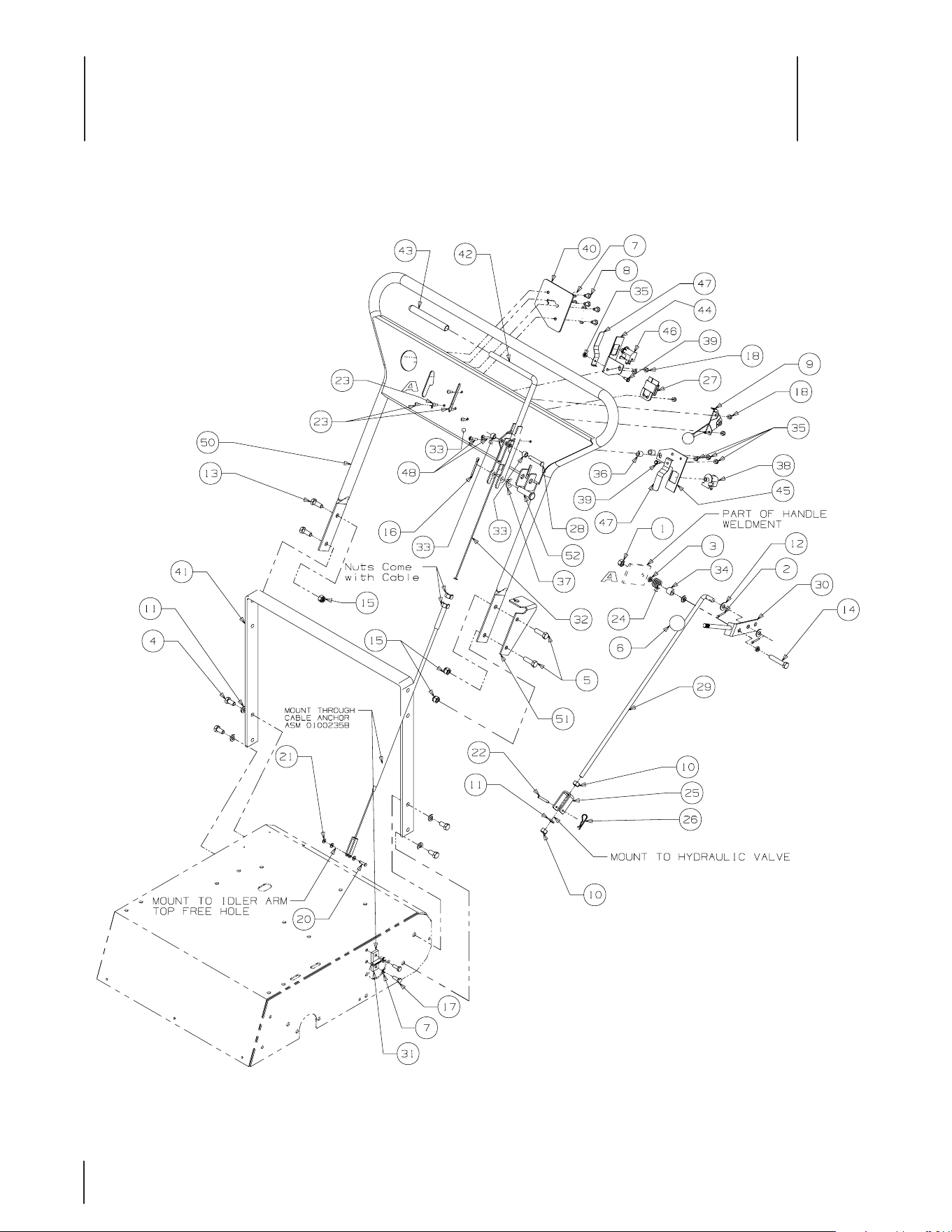
Handle Assembly - Fig. 1
GD: 02004211-03/27/08

19
3
Handle Assembly - Parts List For Fig. 1
Ref.
No. Part No. Description Qty.
1 912-3017 Hex Nut, 3/8-16 1
2 914-0474 Cotter Pin, 1/8 x 3/4 2
3 00011075 Flat Washer, 5/16 3
4 710-3119 Hex Cap Screw, 3/8-16 x 3/4 4
5 00011444
Hex Cap Screw, 3/8-16 x 1 1/4
2
6 00012118 Knob, 1-3/8 x 1-19/64, 3/8-24 1
7 936-0329 Lock Washer, 1/4 6
8 710-3013 Hex Cap Screw, 1/4-20 x 1/2 4
9 00012149 Engine Throttle Cable 1
10 00012156 Hex Nut, 3/8-24 2
11 936-0169 Lock Washer, 3/8 5
12 00012158 Flat Washer, 3/8 2
13 00012171 Hex Cap Screw, 3/8-16 x 1 2
14 00012172 Hex Cap Screw, 3/8-16 x 2 1
15 712-04065 Lock Nut, Nylon Insert, 3/8-16 4
16 00012380 Cotter Pin, 5/32 x 1-1
/2 1
1
7 710-3015 Hex Cap Screw, 1/4-20, .75 2
18 00014608 Lock Nut, Nylon Insert, #10-32 5
19 00014624 Splice Clip (not shown) 1
20 00014630 Clevis Pin, 3/16 x 3/4 1
21 00016771 Flat Washer, 3/16 3
22 00017568 Clevis Pin, 3/16 x 1-1/4 1
23 00017778
Round Head Mach. Screw, 10-32 x 1/2
5
24 00021797 Spring, .850 OD x 1 1
25 00021837 Clevis, Shift 1
26 00021956
3/8"-1/2" Hair Pin
3
27 00030585 Module Volt Sensor 1
28 00032153 Clevis Pin, 5/16 x 1-5/8 1
29 00033601 Shift Lever Rod 1
30 00033746 Direction Control Lever 1
31 00035104 Cable Anchor Assembly 1
32 00036730 Control Cable Ad
justment Blade 1
33 00062715 Turnbuckle Sleeve 2
34 00076730 Sleve Spring, 32/36/48 1
35 712-0161 Nylon Lock Nut, #10-24 4
36 01000799 Spacer, .265 x .500 x .562 2
37 936-0160 Flat Washer, .536 ID x .930 OD x .05 1
38 01001717 Snap Mounting Switch, NC 1
39 01001864 Hex Index Washer Screw, #10-24 2
40 01005907 Mounting Plate Valve 1
41 00030011 Lower Handle 1
42 01005453 Slicer Control Lever 1
43 01005459 Sleeve, 1/2” ID x 5.00" Long 1
44 01008063 Safety Switch Bracket 1
45 01008064 Slicer Safety Switch Bracket 1
46 01008028 Snap Mounting Switch, NO 1
47 732-04200 Retainer
Spri
ng 2
48 01008046
Pan Head Machine Screw, 10-24 x 3/4
2
49 01008057 Wire Harness (not shown) 1
50 01008066 Handle Assembly 1
51 01008098 Lower Handle Slicer Bracket 1
52 711-04997 Clevis Pin, .500 DIA. x 1.75 LG. 1
20
4
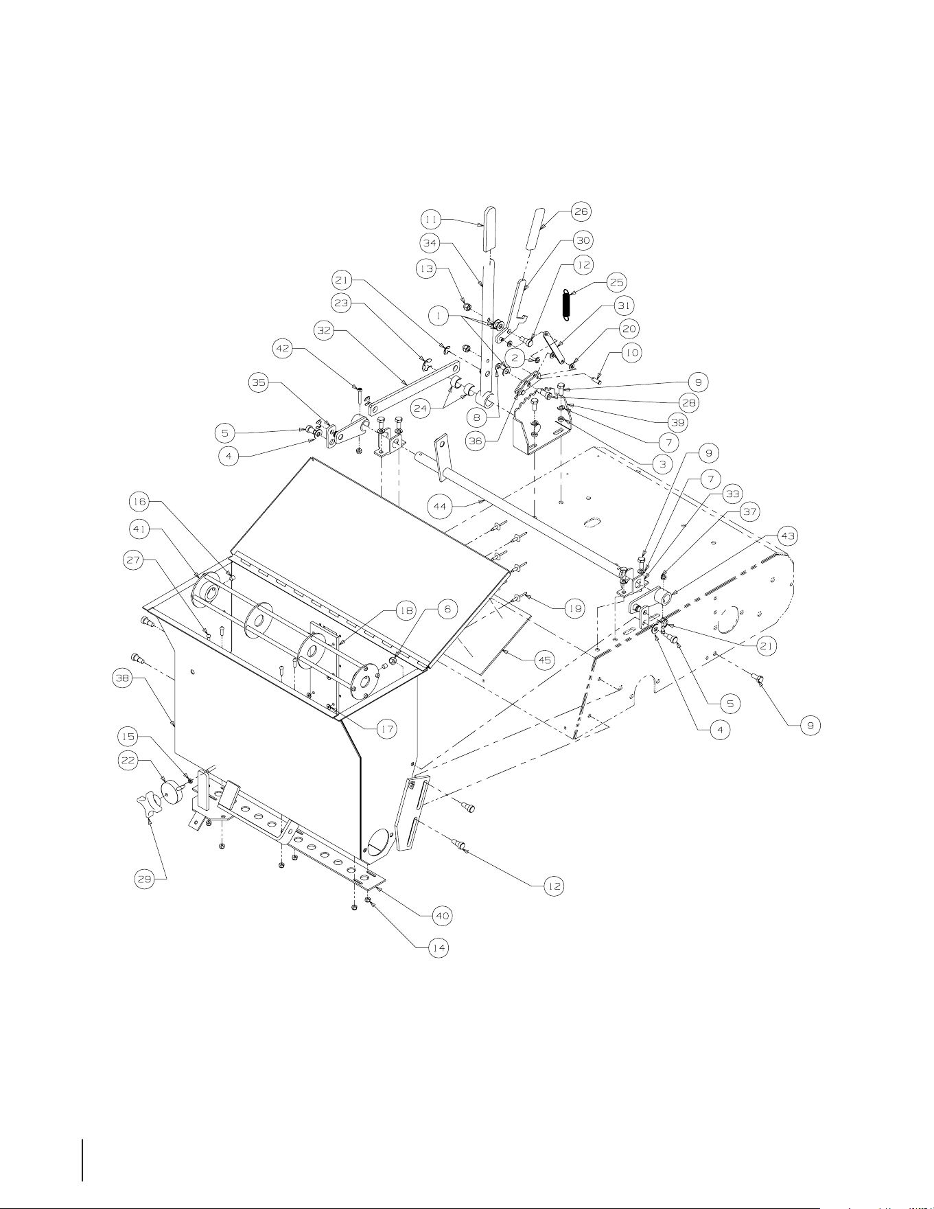
Hopper Lift Assembly
GD: 02004210-04/09/08
- Fig. 2

21
5
Hopper Lift Assembly
Ref.
No. Part No. Description Qty.
1 00005530 Flat Washer, Nylon, 3/8 3
2 00010171 Retainer Clip, “C” 1
3 00011075 Flat Washer, 5/16 2
4 00012158 Flat Washer, 3/8 2
5 00012160 Socket Shoulder Bolt, 3/8 x 12 2
6 912-0429 Nylock Nut, 5/16-18 2
7 936-0119 Lock Washer, 5/16 6
8 00012169 Flat washer, 5/16 1
9 00012179 Hex Cap Screw, 5/16-18 x 3/4 8
10 00012609 Clevis Pin, 1/4 x 3/4 1
11 00013595 Grip, .250 x 1.0 x 4 1
12 00013733 Shoulder Bolt, 3/8 x 3/8 5
13 00014561 Acorn Nut, 5/16-18 2
14 00014608 Lock Nut, Nylon Insert, #10-32 6
15 00016044 Flat Washer, 1/4 1
16 00016358 Cap Screw, 5/16-18 x 5/16 2
17 00016771 Flat Washer, 3/16 6
18 0001759
7
Clear Plate 1
19 00017732 POP Rivet, 3/16 6
20 00018628 Nylon Washer, 1/4 3
21 00019795 E-Ring, 1/2” 4
22 00021826 Hopper Dial Assembly 1
23 00021961 E-Ring, Retainer 1
24 741-04333 Sintered Bearing 2
25 00030020 Spring Reel Enlargement 1
26 00030899 Grip, 3.5” 1
27 00030906 Machine Screw, 10-32 x 5/8 6
28 00031885 Shoulder Bolt, 3/8 x 5/8 1
29 00060043 Knob Control Rate 1
30 00082159 Hopper Lift, Pivot Assembly 1
31 00082292 Hopper Lift, Link, Short 1
32 00082300 Hopper Lift, Link, Long 1
33 00082743 Hopper Assembly, Lift Support 2
34 00083477
Hopper Lift, Handle Assembly Bearing
1
35 00083661 Hopper Lift, Link 2
36 00084102 Hopper Lift, Latch Assembly 1
37 712-0161 Nylon
Lock Nut, #10-24 2
38 02004208 Hopper Assembly Cover 1
39 01002352-
0637
Hopper Lift, Bracket Assembly 1
40 01002365-
0637
Metering Bar Assembly 1
41 01002367-
0637
Agitator Assembly 1
42 01003133 Socket Screw, #10-24 x 1.25 2
43 01007917 Hopper Lift, Arm Assembly 2
44 01007925 Hopper Lift Assembly 1
45 00031742 Step, 6” Roll Safety Adhesive 1
- Parts List For Fig. 2
22
6
This is a double pulley
attached to the engine.
This pulley attaches to ref. no. 45
Disc shaft assembly
Description Part Number
Engine
Filter
Foam Wrap
Fuel Filter
Muffler
Gasket Muffler
Sparkplug
This part is from page 8 and 9 Ref. No. 21
Sheave Pulley connected to Hydraulic Pump.
KM-11013-2128
KM-11013-2129
KM-49019-2095
KM-49069-22779X
KM-11009-2487
KM-BPR5ES
01001002

23
7
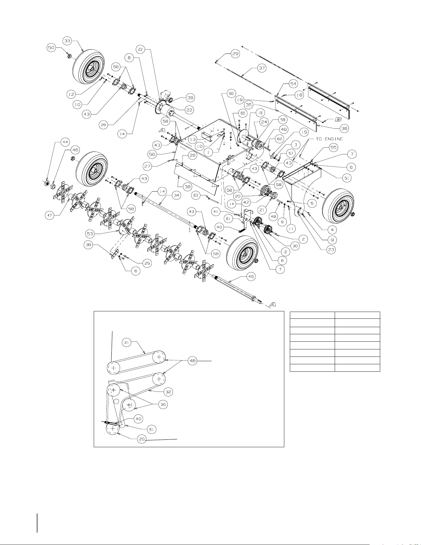
Deck Assembly Kawasaki - Parts List For Fig. 3
Ref.
No. Part No. Description Qty.
Ref.
No. Part No. Description Qty.
1 00011075 Flat Washer, 5/16 4
2 00011438 Hex Cap Screw, 3/8-16 x 1-1/2 3
3 00012062 Lock Washer, M10 1
35 00021819 Brush 2
4 00012133 Hex Cap Screw, 1/4-20 x 1/2 1
36 00021822 Brush Guard 3
5 00012152 Lock Nut, Nylon Insert, 1/4-20 1
37 00021824 Brush Mounting Shaft 2
6 736-0169 Lock Washer, 3/8 85
38 00030001 Heavy Duty Blade 40
7 00012158 Flat Washer, 3/8 4
39 00030014 Sprocket Drive Motor 1
8 712-0429 Nylock Nut, 5/16-18 4
40 00030020 Reel Enlargement Spring 1
9 00012166 Hex Nut, 5/16-18 2
41 00030342 Bellecrank Pivot Tube 1
10 736-0119 Lock
W
asher, 5/16 15
42 00033670 Key, 1/4 x 1/4 x 1-1/4 1
11 00012169 Flat Washer, 5/16 1
43 00034995 Flanged Ball Bearing 6
12 00012179 Hex Cap Screw, 5/16-18 x 3/4 12
44 00035603 Hex Lock Nut, 1-1/4-12 1
13 00012382 Hex Cap Screw, 5/16-18 x 1-1/2 4
45 00063635 Disc Shaft Assembly 1
14 00013397 Groove Pin, 1/4 x 1-1/2 4
46 00064498 Disc Blade Spacer Assembly 1
15 00013675 Clutch Washer 1
47 00064591 Blade Disc Spacer 9
16 00014394 Hex Cap Screw, M8-1.25, 120.0 1
48 01000165 Double Pulley, 2.65 Dia. 3.15 Dia. 1
17 00014601 Chain, Master Link 21-1/2 1
49 01000395 Spacer, Stop Deck 1
18 00014602 Round Head Machine Screw, 10
-32
x 3/4 6
50 01000678 Jam Nut Insertion Lock, 1.0 -14 4
19 00014651 Nut, Keeper, #10-32 6
51 01000720 Hex Cap Screw, M8-1.25 x 25mm 2
20 00014655 Sheave Pulley 1
52 01001002 8HP Kawasaki Engine (not shown) 1
21 00014673 Sheave Bushing 1
53 02004309 Disc Blade 10
22 00016338 Sprocket 1
54 01002328-
0637
Brush Clip Assembly 2
23 00016344 Belt Guard Bracket 1
55 01002369-
0421
Belt Guard Assembly 1
24 00016358 Cap Screw, 5/16-18 x 5/16 1
56 01002373-
0421
Power Deck Assembly 1
25 00016362 Hex Cap Screw, 3/8-24 x 1/2 80
57 01002885 Hex Cap Screw, M10x1.5, 30mm, GR10.9 1
26 00016771 Flat Washer, 3/16 3
58 741-0242 Flange Bearing Cover 12
27 0001773
2 POP, Rivet, 3/16 3
59 01004981 Belt Guide Rod, M8-1.25 1
28 00021795 Differential 1
60 01004982 Hex Nut Center Lock, M8 2
29 00021804 Push-On Cap, 1/4 4
61 00030341 Blade Clutch with Bearings, Bellecrank
Assembly
1
30 00021810 Pulley 2
62 01007533 Key, 1/4 x 1/4 x 2-3/4 1
31 00021811 Power Wedge COG 26.1" OD, Pump Belt 1
63 02002974 Tap Bolt, 5/16-18 x 4.00 1
32 00021812 2 Rib Blade Belt 1
33 00021813 Wheel Assy, 13-5 x 6 4
34
00021818 Shaft Agitator 1

24

25

CALIFORNIA EMISSION CONTROL WARRANTY STATEMENT
YOUR WARRANTY RIGHTS AND OBLIGATIONS
The California Air Resources Board and MTD Consumer Group Inc are pleased to explain the evaporative emission control system warranty on your 2008 lawn
mower. In California, new lawn mowers must be designed, built and equipped to meet the State’s stringent anti-smog standards. MTD Consumer Group Inc must
warrant the EECS on your lawn mower for the period of time listed below provided there has been no abuse, neglect or improper maintenance of your lawn mower.
Your EECS may include parts such as the carburetor, fuel-injection system, the ignition system, catalytic converter, fuel tanks, fuel lines, fuel caps, valves,
canisters, filters, vapor hoses, clamps, connectors, and other associated emission-related components.
Where a warrantable condition exists, MTD Consumer Group Inc will repair your lawn mower at no cost to you including diagnosis, parts and labor.
MANUFACTURER’S WARRANTY COVERAGE:
This evaporative emission control system is warranted for two years. If any evaporative emission-related part on your equipment is defective, the part will be
repaired or replaced by MTD Consumer Group Inc.
OWNER’S WARRANTY RESPONSIBILITIES:
As the lawn mower owner, you are responsible for performance of the required maintenance listed in your owner’s manual. MTD Consumer Group Inc recommends
that you retain all receipts covering maintenance on your lawn mower, but MTD Consumer Group Inc cannot deny warranty solely for the lack of receipts.
As the lawn mower owner, you should however be aware that MTD Consumer Group Inc may deny you warranty coverage if your lawn mower or a part has failed
due to abuse, neglect, or improper maintenance or unapproved modifications.
You are responsible for presenting your lawn mower to MTD Consumer Group Inc’s distribution center or service center as soon as the problem exists. The
warranty repairs should be completed in a reasonable amount of time, not to exceed 30 days. If you have a question regarding your warranty coverage, you should
contact the MTD Consumer Group Inc Service Department at 1-800-800-7310.
GENERAL EMISSIONS WARRANTY COVERAGE:
MTD Consumer Group Inc warrants to the ultimate purchaser and each subsequent purchaser that the lawn mower is: Designed, built and equipped so as to
conform with all applicable regulations; and free from defects in materials and workmanship that cause the failure of a warranted part to be identical in all material
respects to that part as described in MTD Consumer Group Inc’s application for certification.
The warranty period begins on the date the lawn mower is delivered to an ultimate purchaser or first placed into service. The warranty period is two years.
Subject to certain conditions and exclusions as stated below, the warranty on emission-related parts is as follows:
1. Any warranted part that is not scheduled for replacement as required maintenance in the written instructions supplied, is warranted for the warranty period
stated above. If the part fails during the period of warranty coverage, the part will be repaired or replaced by MTD Consumer Group Inc according to subsection
(4) below. Any such part repaired or replaced under warranty will be warranted for the remainder of the period.
2. Any warranted part that is scheduled only for regular inspection in the written instructions supplied is warranted for the warranty period stated above. Any such
part repaired or replaced under warranty will be warranted for the remaining warranty period.
3. Any warranted part that is scheduled for replacement as required maintenance in the written instructions supplied is warranted for the period of time before the
first scheduled replacement date for that part. If the part fails before the first scheduled replacement, the part will be repaired or replaced by MTD Consumer
Group Inc according to subsection (4) below. Any such part repaired or replaced under warranty will be warranted for the remainder of the period prior to the
first scheduled replacement point for the part.
4. Repair or replacement of any warranted part under the warranty provisions herein must be performed at a warranty station at no charge to the owner.
5. Notwithstanding the provisions herein, warranty services or repairs will be provided at all of our distribution centers that are franchised to service the subject
engines or equipment.
6. The lawn mower owner will not be charged for diagnostic labor that is directly associated with diagnosis of a defective, emission-related warranted part,
provided that such diagnostic work is performed at a warranty station.
7. MTD Consumer Group Inc is liable for damages to other engine or equipment components proximately caused by a failure under warranty of any warranted
part.
8. Throughout the lawn mower warranty period stated above, MTD Consumer Group Inc will maintain a supply of warranted parts sufficient to meet the expected
demand for such parts.
9. Any replacement part may be used in the performance of any warranty maintenance or repairs and must be provided without charge to the owner. Such use will
not reduce the warranty obligations of MTD Consumer Group Inc.
10. Add-on or modified parts that are not exempted by the Air Resources Board may not be used. The use of any non-exempted add-on or modified parts by the
ultimate purchaser will be grounds for disallowing a warranty claims. MTD Consumer Group Inc will not be liable to warrant failures of warranted parts caused
by the use of a non-exempted add-on or modified part.

WARRANTED PARTS:
The repair or replacement of any warranted part otherwise eligible for warranty coverage may be excluded from such warranty coverage if MTD Consumer Group
Inc demonstrates that the lawn mower has been abused, neglected, or improperly maintained, and that such abuse, neglect, or improper maintenance was the
direct cause of the need for repair or replacement of the part. That notwithstanding, any adjustment of a component that has a factory installed, and properly
operating, adjustment limiting device is still eligible for warranty coverage. The following emission warranty parts are covered:
(1) Fuel Metering System
•Coldstartenrichmentsystem(softchoke)
•Carburetorandinternalparts
•Fuelpump
•Fueltank
(2) Air Induction System
•Aircleaner
•Intakemanifold
(3) Ignition System
•Sparkplug(s)
•Magnetoignitionsystem
(4) Exhaust System
•Catalyticconverter
•SAI(Reedvalve)
(5) Miscellaneous Items Used in Above System
•Vacuum,temperature,position,timesensitivevalvesandswitches
•Connectorsandassemblies
(6) Evaporative Control
•FuelhosecertifiedforARBevaporativeemissions2008
•Fuelhoseclamps
•Tetheredfuelcap
•Carboncanister
•Vaporlines
GDOC-100175 Rev. C

CUB CADET LLC
MANUFACTURER’S LIMITED WARRANTY
FOR COMMERCIAL LAWN APPLICATION EQUIPMENT
Cub Cadet LLC, P.O. BOX 361131 CLEVELAND, OHIO 44136-0019, Phone: 1-877-282-8684
MTD Products Limited, Kitchener, ON N2G 4J1, Phone: 1-800-668-1238
GDOC-100208 REV. A
IMPORTANT: To obtain warranty coverage owner must present an
original proof of purchase and applicable maintenance records to the
servicing dealer. Please see the operator’s manual for information on
required maintenance and service intervals.
The limited warranty set forth below is given by Cub Cadet LLC with
respect to new merchandise purchased or leased and used in the
United States and/or its territories and possessions, and by MTD
Products Limited with respect to new merchandise purchased or
leased and used in Canada and/or its territories and possessions
(either entity respectively, “Cub Cadet”).
Cub Cadet warrants this product (excluding its Normal Wear Parts,
Batteries and Attachments as described below) against defects in
material and workmanship for a period of one (1) year commencing
on the date of original retail purchase or lease and will, at its option,
repair or replace, free of charge, any part found to be defective in
materials or workmanship.
Normal Wear Parts are warranted to be free from defects in material
and workmanship for a period of thirty (30) days or one hundred
(100) operation hours, whichever comes first, commencing on the
date of original retail purchase or lease. Normal wear parts include,
but are not limited to items such as: belts, blades, blade adapters,
grass bags, rider deck wheels, seats, and tires.
Batteries have a one-year prorated limited warranty against defects
in material and workmanship, with 100% replacement during the
first three months. After three months, the battery replacement
credit is based on the months remaining in the twelve (12) month
period dating back to the original date of original sale or lease. Any
replacement battery will be warranted only for the remainder of the
original warranty period.
Attachments — Cub Cadet warrants attachments for this product
against defects in material and workmanship for a period of one (1)
year, commencing on the date of the attachment’s original purchase
or lease. Attachments include, but are not limited to items such as:
grass collectors and mulch kits.
This limited warranty shall only apply if this product has been
operated and maintained in accordance with the Operator’s Manual
furnished with the product, and has not been subject to misuse,
abuse, neglect, accident, improper maintenance, alteration,
vandalism, theft, fire, water, or damage because of other peril or
natural disaster. Damage resulting from the installation or use of any
part, accessory or attachment not approved by Cub Cadet for use
with the product(s) covered by this manual will void your warranty as
to any resulting damage. In addition, Cub Cadet may deny warranty
coverage if the hour meter, or any part thereof, is altered, modified,
disconnected or otherwise tampered with.
HOW TO OBTAIN SERVICE: Warranty service is available, WITH
PROOF OF PURCHASE AND APPLICABLE MAINTENANCE RECORDS,
through your local authorized service dealer. To locate the dealer in
your area:
In the U.S.A.:
Check your Yellow Pages, or contact Cub Cadet LLC at P.O. Box
361131, Cleveland, Ohio 44136-0019, call 1-877-282- 8684
or log on to our website at www.cubcadet.com.
In Canada:
Contact MTD Products Limited, Kitchener, ON N2G 4J1, call 1-800-
668-1238 or log on to our website at www.mtdcanada.com.
Without limiting the foregoing, this limited warranty does not provide
coverage in the following cases:
a. Routine maintenance items such as lubricants, filters, blade
sharpening, tune-ups, brake adjustments, clutch adjustments,
deck adjustments, and normal deterioration of the exterior finish
due to use or exposure.
b. Service completed by someone other than an authorized service
dealer.
c. Cub Cadet does not extend any warranty for products sold or
exported outside of the United States and/or Canada, and their
respective possessions and territories, except those sold through
Cub Cadet’s authorized channels of export distribution.
d. Replacement parts and\or accessories that are not genuine Cub
Cadet parts.
e. Transportation charges and service calls.
There are no implied warranties, including without limitation any
implied warranty of merchantability or fitness for a particular
purpose. No warranties shall apply after the applicable period
of express written warranty above. No other express warranties
beyond those mentioned above, given by any person or entity,
including a dealer or retailer, with respect to any product, shall
bind Cub Cadet. The exclusive remedy is repair or replacement of
the product as set forth above. The terms of this warranty provide
the sole and exclusive remedy arising from the sale and/or lease
of the products covered hereby. Cub Cadet shall not be liable for
any incidental or consequential loss or damage including, without
limitation, expenses incurred for substitute or replacement lawn
care services or for rental expenses to temporarily replace a
warranted product.
Some jurisdictions do not allow the exclusion or limitation of
incidental or consequential damages, or limitations on how long an
implied warranty lasts, so the above exclusions or limitations may not
apply to you.
In no event shall recovery of any kind be greater than the amount of
the purchase price of the product sold. Alteration of safety features of
the product shall void this warranty. You assume the risk and liability
for loss, damage, or injury to you and your property and/or to others
and their property arising out of the misuse or inability to use the
product.
This limited warranty shall not extend to anyone other than the
original purchaser or to the person for whom it was purchased as a
gift.
HOW LOCAL LAWS RELATE TO THIS WARRANTY: This limited
warranty gives you specific legal rights, and you may also have other
rights that vary in different jurisdictions.

