CUB CADET LLC, P.O. BOX 361131 CLEVELAND, OHIO 44136-0019
Printed In USA
Op e r a t O r ’s Ma n u a l
Safe Operation Practices • Set-Up • Controls • Operation • Maintenance • Specications • Troubleshooting
WARNING
READ AND FOLLOW ALL SAFETY RULES AND INSTRUCTIONS IN THIS MANUAL
BEFORE ATTEMPTING TO OPERATE THIS MACHINE.
FAILURE TO COMPLY WITH THESE INSTRUCTIONS MAY RESULT IN PERSONAL INJURY.
Form No. 769-06944
(March 11, 2011)
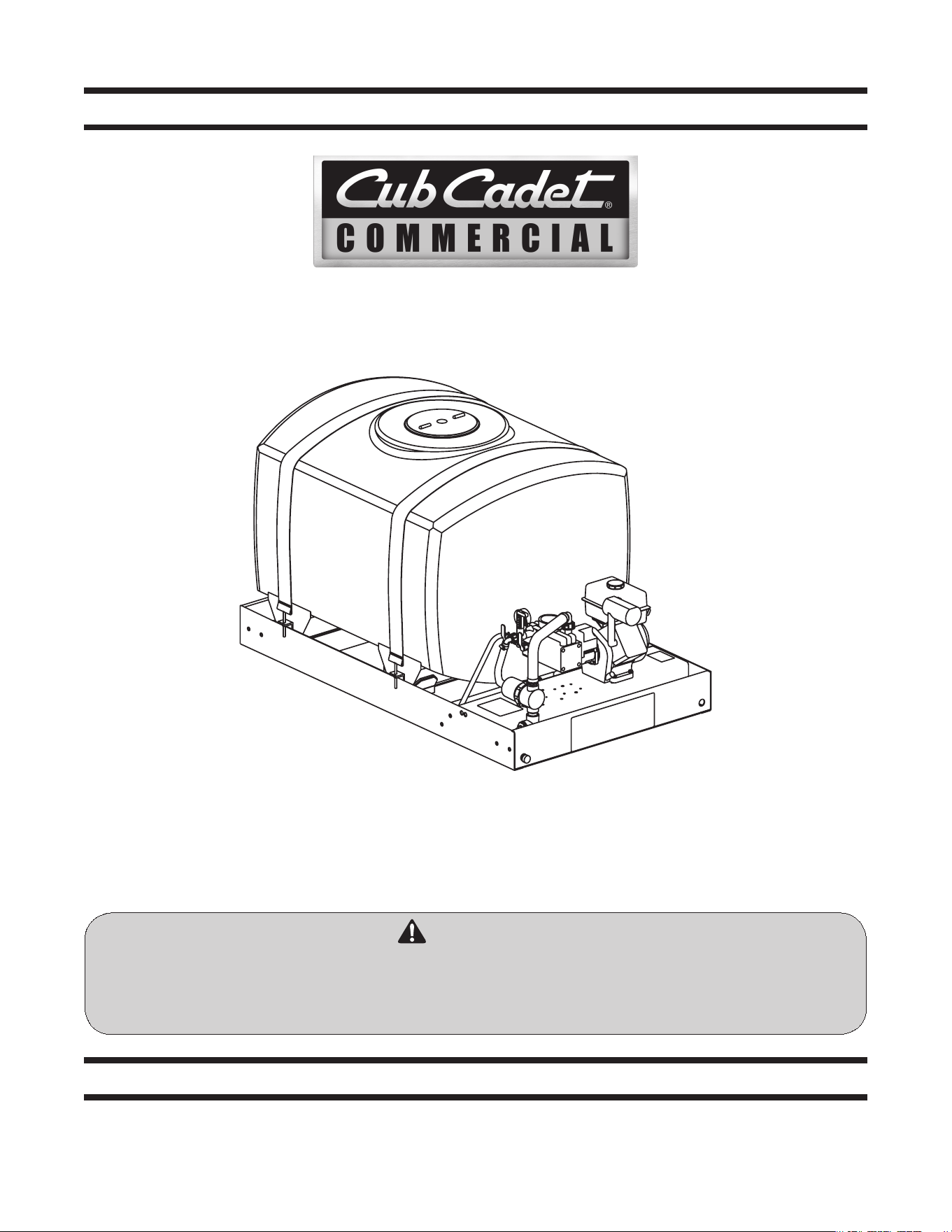
Commercial Tank Sprayers

Customer Support
If you have difficulty assembling this product or have any questions regarding the controls, operation, or maintenance of
this machine, you can seek help from the experts. Choose from the options below:
Visit us on the web at www.cubcadet.com◊
Locate your nearest Cub Cadet Dealer at (877) 282-8684◊
Write us at Cub Cadet LLC • P.O. Box 361131 • Cleveland, OH • 44136-0019◊
Thank you for purchasing your Sprayer manufactured by Cub
Cadet LLC. The Sprayer is designed to provide professional
turf grass managers with reliable spray equipment. The sprayer
includes a polyethylene tank, 4.0 HP Kawasaki gasoline powered
engine and can output a maximum of 6 gallons per minute. It
was carefully engineered to provide excellent performance when
properly operated and maintained.
Please read this entire manual prior to operating the equipment.
It instructs you how to safely and easily set up, operate and
maintain your machine. Please be sure that you, and any other
persons who will operate the machine, carefully follow the
recommended safety practices at all times. Failure to do so could
result in personal injury or property damage.
All information in this manual is relative to the most recent
product information available at the time of printing. Review
this manual frequently to familiarize yourself with the machine,
its features and operation. Please be aware that this Operator’s
Manual may cover a range of product specifications for various
models. Characteristics and features discussed and/or illustrated
in this manual may not be applicable to all models. Cub Cadet
LLC reserves the right to change product specifications, designs
and equipment without notice and without incurring obligation.
If you have any problems or questions concerning the machine,
phone your local Cub Cadet dealer or contact us directly. Cub
Cadet’s Dealer Locator telephone number, web site address and
mailing address can be found on this page. We want to ensure
your complete satisfaction at all times.
Throughout this manual, all references to right and left side of the
machine are observed from the operating position.
The engine manufacturer is responsible for all engine-related
issues with regards to performance, power-rating, specifications,
warranty and service. Please refer to the engine manufacturer’s
Owner’s/Operator’s Manual, packed separately with your
machine, for more information.
Thank You
Record Product Information
Before setting up and operating your new equipment, please
locate the model plate on the equipment and record the
information in the provided area to the right. You can locate the
model plate by looking on the frame just below the engine. This
information will be necessary, should you seek technical support
via our web site or with your local Cub Cadet dealer.
MO d e l nu M b e r
se r i a l nu M b e r
To The Owner
1
2
Safe Operation Practices ........................................ 3
Set-Up ....................................................................... 7
Controls .................................................................... 9
Operation ................................................................11
Maintenance & Adjustments .................................15
Service .....................................................................16
Troubleshooting .....................................................17
Attachments & Accessories ...................................18
Illustrated Parts List ...............................................19
Warranty ..................................................Back Cover
Table of Contents
Important Safe Operation Practices
2
3
General Operation
Read this Operator’s Manual completely before starting the 1.
machine. Study the controls and learn the proper sequence
of operation. Retain Operator’s Manual in a safe place for
future reference.
Do not allow anyone to operate or maintain this machine 2.
who has not read the manual.
Always have your feet and hands clear of the controls when 3.
starting the engine.
Do not remove any shields, guards, decals or safety devices. 4.
If a shield, guard, decal or safety device is damaged or
does not function, repair or replace it before operating the
machine.
If truck or trailer mounted, make certain the sprayer is 5.
securely bolted to the frame of the truck or trailer.
When spraying pesticides:6.
ALWAYS FOLLOW THE DIRECTIONS ON THE LABELa.
Avoid breathing vapors.b.
Avoid contact with skin, eyes or clothing.c.
Wear rubber boots or rubberized shoes.d.
Wear work clothes with long-sleeved shirts and e.
long-legged pants.
Change to clean clothing daily.f.
Wash hands and face before eating or smoking.g.
Bathe thoroughly as soon after spraying as possible.h.
Wear a face shield and rubber gloves when handling 7.
concentrates.
WARNING: This symbol points out important safety instructions which, if not followed,
could endanger the personal safety and/or property of yourself and others. Read and follow
all instructions in this manual before attempting to operate this machine. Failure to comply
with these instructions may result in personal injury.
When you see this symbol. HEED ITS WARNING!
DANGER: This machine was built to be operated according to the safe operation practices in
this manual. As with any type of power equipment, carelessness or error on the part of the
operator can result in serious injury. This machine is capable of amputating fingers, hands,
toes and feet and throwing objects. Failure to observe the following safety instructions could
result in serious injury or death.
WARNING - FOR THE STATE OF CALIFORNIA: A person shall not sell, offer for sale, lease, or
rent to a person any equipment that is powered by an internal combustion engine subject to
Section 4442 or 4443, and not subject to Section 13005 of Health and Safety Code, unless
that equipment has a permanent writing label attached that is in plain view to the operator
that states, ‘WARNING-Operation of This Equipment May Create Sparks That Can Start Fires
Around Dry Vegetation. A Spark Arrestor May be Required. The Operator Should Contact
Local Fire Agencies For Laws or Regulations Relating to Fire Prevention Requirements.’
CALIfORNIA PROPOSITION 65
WARNING: Engine Exhaust, some of its constituents, and certain vehicle components
contain or emit chemicals known to State of California to cause cancer and birth defects
or other reproductive harm.
WARNING: Battery posts, terminals, and related accessories contain lead and lead
compounds, chemicals known to the State of California to cause cancer and reproductive
harm. Wash hands after handling.

4 se c t i O n 2 — iM p O r t a n t sa f e Op e r a t i O n pr a c t i c e s
Always wear safety glasses, long pants and safety shoes 8.
when operating or maintaining this unit. Do not wear
loose-fitting clothing.
Never run the engine indoors without adequate 9.
ventilation. Exhaust fumes are deadly.
To avoid serious burns, do not touch the engine or muffler 10.
while the engine is running or until it has cooled for at least
30 minutes after it has been shut off.
Keep adults, children and pets away from the sprayer and 11.
the area to be sprayed.
Spray only in daylight.12.
Always check the area to be sprayed and remove debris 13.
and other objects prior to spraying.
Always disconnect the spark plug wire to prevent the 14.
engine from accidentally starting before performing any
maintenance on this machine.
Keep the machine and especially the engine/pump area 15.
clean and free of grease, grass and leaves to reduce the
potential for over heating and fire.
General Requirements
Personal Protective Equipment (PPE):
OSHA Standard 1910.132 through 1910.139
OSHA standard 1910.132 states in relevant part:16.
Protective equipment, including personal a.
protective equipment or PPE, for eyes, face, head,
and extremities, protective clothing, respiratory
devices, and protective shields and barriers, shall
be provided, used, and maintained in a sanitary
and reliable condition where ever it is necessary
by reason of hazards of processes or environment,
chemical hazards, radiological hazards, or
mechanical irritants encountered in a manner
capable of causing injury or impairment in the
function of any part of the body through absorption,
inhalation or physical contact.
This standard is subject to change. Please check www.osha.gov
for the latest regulatory updates
General
Sometimes, it is not possible to reduce a hazard by eliminating
it, substituting a less hazardous process or product, making
changes to equipment, or even by changing how you do the job.
That is when you need personal protection.
PPE includes items like gloves, goggles, boots, hearing
protection and respirators. Respirators filter out particles or block
gases and vapors that can harm the respiratory system. With a
surface area well supplied with blood vessels and equal in size to
a tennis court, the lungs are the quickest and most direct route
for absorbing harmful substance into your body.
Note: PPE does not prevent accidents, but it does prevent or
reduce injury and even fatalities when used properly.
Equipment (PPE)
Protective equipment must be selected carefully. Always test
fit the protective equipment to be sure it fits properly and
comfortably. If it is not comfortable — it will not be worn; if it is
not worn — it will not protect. PPE includes:
Respirators•
Chemical-resistant clothing•
Hearing protectors•
Gloves•
Safety goggles and glasses•
Hard hats•
Sensors to detect hazardous substance•
Communication devices used for safe deployment of •
workers
Inhaling pesticide fumes and mists is a very common entry route
of pesticides into the body. Absorption through the lungs is great
and the sensitivity is high.
The National Institute for Occupational Safety and Health
(NIOSH), under authority of the Federal Mine Safety and Health
Act of 1977 and the Occupational Safety and Health Act of 1970,
tests, approves, and certifies respiratory equipment as being safe
for its intended purpose.
Note: Always be certain that the NIOSH compliance number is
on the product before purchasing respiratory equipment.
Two systems of respiratory protection are available, depending
on the type of respiratory risk involved: air-purification (filtering)
and air-supplying. For most pesticide work, the air-purifying
equipment is adequate and safe.
Protective equipment is usually required by the pesticide label in
one form or another and is integral to safe pesticide application.
Chemical-protective clothing consists of multi-layered garments
made out of various materials that protect against a variety
of hazards. Because no single material can protect against all
chemicals, multiple layers of various materials usually are used
to increase the degree of protection. Protection is maximized
by total encapsulation (completely covering the wearer). An
assortment of types of chemical-protective hats, hoods, gloves,
and boot covers are used with the garments.
There are many brands and models of protective equipment
available for use in pesticide application. Price is not always an
indicator of quality, so shop carefully.
Note: Select equipment that is NIOSH tested and approved.
Protective equipment, appropriate for the task and hazards
that an employee could be potentially exposed to, shall be
provided by the employer. Since comfort and proper fit must
be considered, the person who is going to use it must select the
proper size to ensure correct fit and function. Unused protective
equipment does not help anyone.
Note: Many supply centers, hardware stores, chemical retailers,
and equipment/machinery dealers keep protective equipment
in stock.

5se c t i O n 2 — iM p O r t a n t sa f e Op e r a t i O n pr a c t i c e s
Training
Written procedures shall be developed for PPE use. These
procedures shall include all information and guidance necessary
for their proper selection, use and care. The employer shall
provide fitting instructions including demonstrations and
practice in how the PPE should be worn, It is essential that both
supervisors and workers be properly instructed in PPE selection,
use, and maintenance. Training shall provide the workers an
opportunity to handle PPE, and have it fitted properly.
When to replace PPE
All PPE shall be inspected routinely before and after each use. A
program for maintenance and care of PPE shall be initiated and
be adjusted to the type of work place, working conditions, and
hazards. It shall include the following:
Inspection for defects and damage•
Cleaning and disinfecting•
Repair•
Storage•
Many factors influence how long PPE (especially respirators)
remains effective. As well as hours of use, an air-purifying
respirator’s service life is affected by the concentration of dust
and other contaminants in the environment; the user’s body size;
how strenuously the user works while the respirator is worn; and
how the respirator is stored.
Note: As a result, it’s not possible to specify a length of time
after which a respirator should be replaced.
In general, replace a mask or filter when it is visibly dirty or
damaged, or when you experience difficulty breathing through
it. Replace respirator cartridges when you can smell or taste
chemical while or after using the respirator, or according to
the manufacturer’s recommendations. Replacement or repairs
shall be done only by experienced person with parts designed
for the PPE. No attempts shall be made to replace components
or to make adjustments or repairs beyond the manufacturer’s
recommendations.
Service
Safe Handling of Gasoline:
To avoid personal injury or property damage use extreme 1.
care in handling gasoline. Gasoline is extremely
flammable and the vapors are explosive. Serious
personal injury can occur when gasoline is spilled on
yourself or your clothes which can ignite. Wash your skin
and change clothes immediately.
Use only an approved gasoline container.a.
Never fill containers inside a vehicle or on a truck b.
or trailer bed with a plastic liner. Always place
containers on the ground away from your vehicle
before filling.
When practical, remove gas-powered equipment c.
from the truck or trailer and refuel it on the ground.
If this is not possible, then refuel such equipment on
a trailer with a portable container, rather than from a
gasoline dispenser nozzle.
Keep the nozzle in contact with the rim of the fuel d.
tank or container opening at all times until fueling is
complete. Do not use a nozzle lock-open device.
Extinguish all cigarettes, cigars, pipes and other e.
sources of ignition.
Never fuel machine indoors.f.
Never remove gas cap or add fuel while the engine g.
is hot or running. Allow engine to cool at least two
minutes before refueling.
Never over fill fuel tank. Fill tank to no more than ½ h.
inch below bottom of filler neck to allow space for
fuel expansion.
Replace gasoline cap and tighten securely.i.
If gasoline is spilled, wipe it off the engine and j.
equipment. Move machine to another area. Wait 5
minutes before starting the engine.
To reduce fire hazards, keep machine free of grass, k.
leaves, or other debris build-up. Clean up oil or fuel
spillage and remove any fuel soaked debris.
Never store the machine or fuel container inside l.
where there is an open flame, spark or pilot light
as on a water heater, space heater, furnace, clothes
dryer or other gas appliances.
Allow a machine to cool at least five minutes before m.
storing.
General Service
Never run an engine indoors or in a poorly ventilated area. 1.
Engine exhaust contains carbon monoxide, an odorless,
and deadly gas.
Before cleaning, repairing, or inspecting, make certain all 2.
moving parts have stopped. Disconnect the spark plug
wire and ground against the engine to prevent unintended
starting.
Keep all nuts, bolts, and screws tight to be sure the 3.
equipment is in safe working condition.
Never attempt to make adjustments or repairs to the 4.
machine while the engine is running.
For safety protection, frequently check components 5.
and replace immediately with original equipment
manufacturer’s (O.E.M.) parts only, listed in this manual.
“Use of parts which do not meet the original equipment
specifications may lead to improper performance and
compromise safety!”
Do not change the engine governor settings or over-speed 6.
the engine. The governor controls the maximum safe
operating speed of the engine.
Maintain or replace safety and instruction labels, as 7.
necessary.
Observe proper disposal laws and regulations for gas, oil, 8.
etc. to protect the environment.
6 se c t i O n 2 — iM p O r t a n t sa f e Op e r a t i O n pr a c t i c e s
WARNING: Your Responsibility—Restrict the use of this power machine to persons who read, understand and
follow the warnings and instructions in this manual and on the machine.
SAVE THESE INSTRUCTIONS!
Do not modify engine
To avoid serious injury or death, do not modify engine in any
way. Tampering with the governor setting can lead to a runaway
engine and cause it to operate at unsafe speeds. Never tamper
with factory setting of engine governor.
Notice Regarding Emissions
Engines which are certified to comply with California and federal
EPA emission regulations for SORE (Small Off Road Equipment)
are certified to operate on regular unleaded gasoline, and
may include the following emission control systems: Engine
Modification (EM), Oxidizing Catalyst (OC), Secondary Air
Injection (SAI) and Three Way Catalyst (TWC) if so equipped.
Spark Arrestor
WARNING! This machine is equipped with an
internal combustion engine and should not be used
on or near any unimproved forest-covered, brush
covered or grass-covered land unless the engine’s
exhaust system is equipped with a spark arrestor
meeting applicable local or state laws (if any).
If a spark arrestor is used, it should be maintained in effective
working order by the operator. In the State of California the
above is required by law (Section 4442 of the California Public
Resources Code). Other states may have similar laws. Federal laws
apply on federal lands.
A spark arrestor for the muffler is available through your
nearest engine authorized service dealer or contact the service
department, P.O. Box 361131 Cleveland, Ohio 44136-0019.
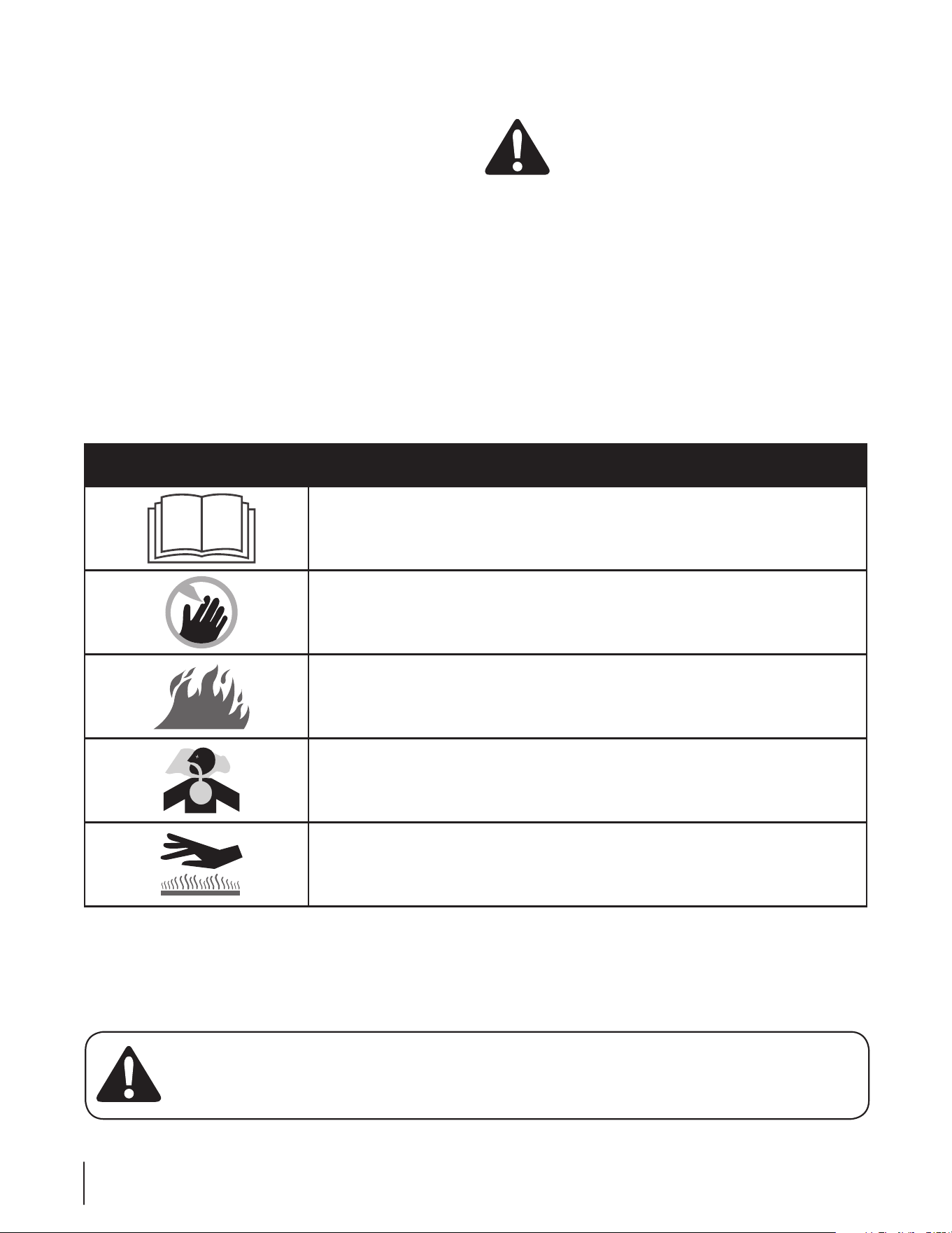
Safety Symbols
This page depicts and describes safety symbols that may appear on this product. Read, understand, and follow all instructions on the
machine before attempting to assemble and operate.
Symbol Description
READ THE OPERATOR’S MANUAL(S)
Read, understand, and follow all instructions in the manual(s) before attempting to
assemble and operate
DANGER — ROTATING BLADES
To reduce the risk of injury, keep hands and feet away. Do not operate unless discharge cover
or grass catcher is in its proper place. If damaged, replace immediately.
WARNING—GASOLINE IS FLAMMABLE
Allow the engine to cool at least two minutes before refueling.
WARNING— CARBON MONOXIDE
Never run an engine indoors or in a poorly ventilated area. Engine exhaust contains carbon
monoxide, an odorless and deadly gas.
WARNING— HOT SURFACE
Engine parts, especially the muffler, become extremely hot during operation. Allow engine
and muffler to cool before touching.
Set-Up
3
7
Set-Up
Installing on a Vehicle
Once the sprayer is in the desired position in your van or pickup
truck, it should be securely bolted through the truck bed to
the vehicle’s frame. Bolts should be used at each corner of the
sprayer’s frame and should be either cap screws placed through
the holes punched in the frame for this purpose or large U-bolts
or J-bolts over the sprayer’s steel frame and down through the
truck bed to the vehicle’s frame. Bolts of at least 3⁄8” diameter
should be used for a 50 gallon sprayer, 1⁄2” diameter for a 100
gallon sprayer, 5⁄8” diameter for a 200 gallon sprayer and 7⁄8” for
a 300 gallon sprayer. Mounting hardware is not supplied for the
sprayer because the installation will vary with each vehicle.
Wiring
Materials furnished if sprayer is equipped with an electric hose reel:
40 amp. Circuit Breaker (1)•
Cable Ties (5)•
Insulated Ring Terminals #8 Wire x • 5⁄16” Stud (2)
Insulated Ring Terminals #8 Wire x # 10 Stud (2)•
#8 Insulated Wire (14’)•
Tools Needed:
Wire Cutter•
Crimping Tool•
Screwdriver•
Adjustable Wrench•
Electric Drill.•
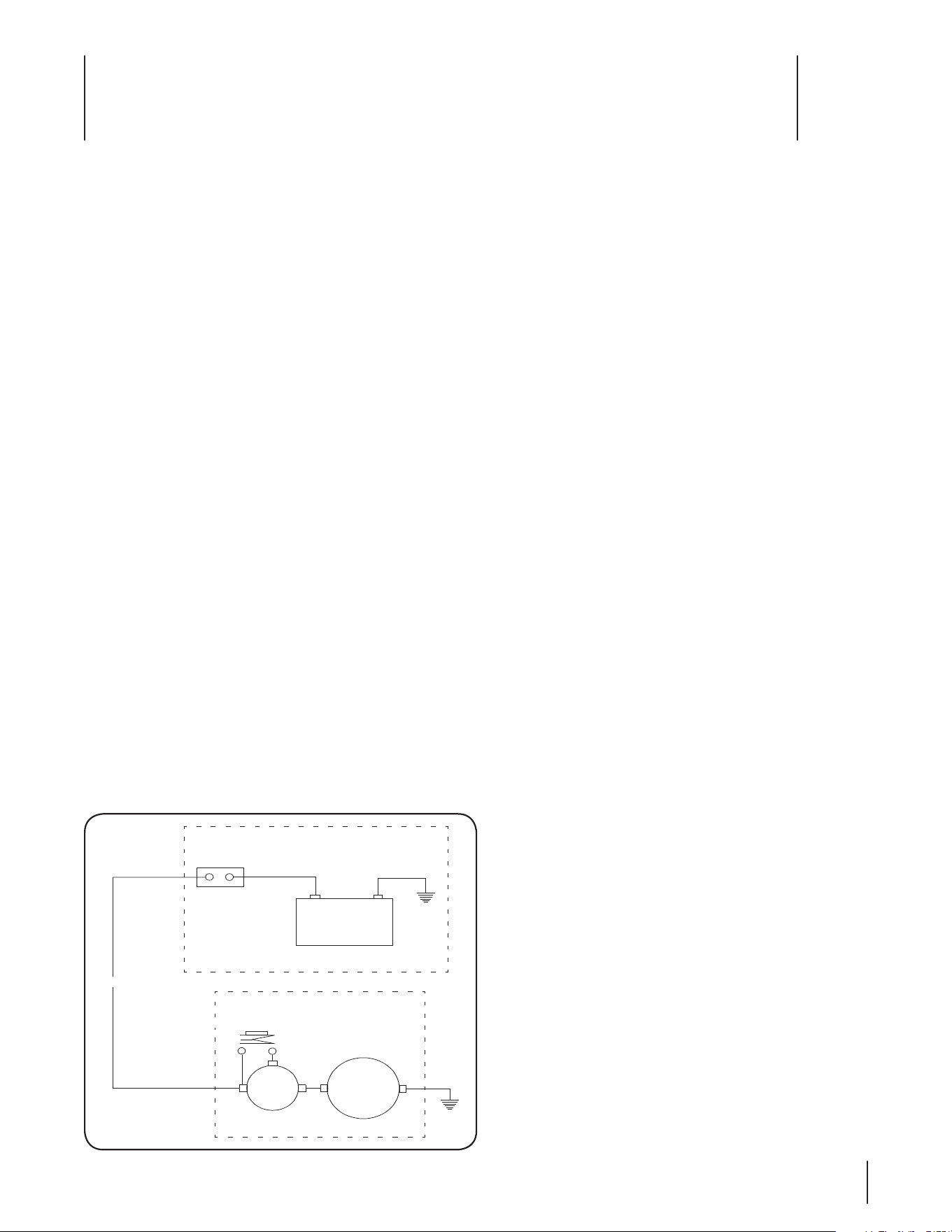
The following instructions are for providing electrical power to
the electric hose reel if your sprayer is so equipped. The vehicle
or sprayer’s battery should be a 12-volt DC automotive-type. The
vehicle can have either a positive or negative ground system and
therefore polarity is not shown on the wiring diagram. See Fig. 3-1.
Disconnect the ground cable from the vehicle’s battery.1.
Install the circuit breaker in the engine compartment near 2.
the vehicle’s battery but away from sources of heat or
humidity.
Cut the required length of #8 wire to reach from the 3.
ungrounded terminal of the battery to the terminal marked
“BAT” on the circuit breaker.
Attach a 4. 5⁄16” ring terminal on one end and a #10 ring
terminal on the other end. Connect this wire to the
ungrounded terminal of the battery and the terminal
marked “BAT” on the circuit breaker.
Attach a #10 ring terminal to one end of the remaining #8 5.
wire and connect it to the terminal marked “AUX” on the
circuit breaker.
Work the loose end of the #8 wire either under the vehicle 6.
or through the fire wall (depending on your vehicle) to
reach the sprayer. Take advantage of any existing cable ties
or clamps along the way to support the wire and use the
enclosed cable ties where needed.
Bring the wire to the solenoid mounted on the reel frame 7.
and cut it off at the proper length. Attach a 5⁄16” ring
terminal to the wire and connect it to the large solenoid
terminal opposite the one to which the reel motor lead is
connected.
Ground the frame of the sprayer to the vehicle body as 8.
follows:
Note: If the sprayer has been properly bolted to the
frame of the vehicle with bolts passing through or over
the sprayer’s frame and the vehicle’s frame, the sprayer Is
grounded and this step may be omitted.
Locate a vehicle body bolt near or under the a.
sprayer’s frame that can be easily removed and
replaced.
Place a bolt through the nearest punched hole in the b.
sprayer’s frame.
Cut the remaining #8 wire to the proper length to c.
reach between these two bolts. Strip approximately
one inch of insulation from each end of the wire.
Remove the bolts or nuts and scratch off any paint d.
that would prevent making metal to metal contact.
Wrap the stripped end of the wire around each bolt e.
and replace the bolts or nuts.
Reconnect the ground cable removed from the battery in 9.
Step 1.
Test the circuit by pulling some hose from the reel and 10.
then pushing the reel switch located on the reel mounting
frame. The reel should retrieve the hose. If your vehicle
has a positive ground system, the reel will run in reverse
and spill out hose. To make the reel rotate in the proper
direction, reverse the reel motor leads. Take the motor lead
that goes to the solenoid and interchange it with the lead
that is grounded to the motor mounting.
12 V. Vehicle
Battery
40 AMP
Circuit
Breaker
#8 Wire to Sprayer
Push-Button Switch
Solenoid
Reel
Motor
Engine Compartment
Sprayer
Figure 3-1

8 se c t i O n 3— se t -up
Gas and Oil Fill-up
WARNING! Use extreme care when handling
gasoline. Gasoline is extremely flammable and the
vapors are explosive. Never fuel machine indoors or
while the engine is hot or running. Extinguish
cigarettes, cigars, pipes, and other sources of
ignition.
Note: Your sprayer is shipped with motor oil in the engine.
However, you MUST check the oil level before operating. Be
careful not to overfill.
Check the engine oil level. Fill to the proper level with the 1.
oil recommended in the Engine Operator’s manual.
Check the engine gasoline level and fill according to the 2.
instructions in the Engine Operator’s manual.

Controls & Features
4
9
Engine Controls
See the separate Engine Operator’s Manual for information and
functions of the engine controls.
Tank
Sturdy, rotationally molded, rectangular shaped, polyethylene
tanks in 50, 100, 200 or 300 gallon capacities. The 200 gallon
tank has a 10 inch fillwell. The fillwell is equipped with a strainer
basket and a screw-on, leak proof lid. The 50, 100 and 300 gallon
tanks have 10 inch fillwells equipped with strainer baskets and
splash-guard covers. All of the tanks have gallonage markers
molded into the plastic.
Frame
50 Gallon frames are constructed of eleven gauge steel. 100, 200
And 300 gallon frames are constructed of ten gauge steel while
engine and pump bases are formed into channels from seven
gauge steel and then electric-welded to the frames to form a
rigid, unitized assembly. All frames have punched holes to accept
optional accessories.
Engine/Pump
Electric 12-volt permanent magnet motor driven four-diaphragm
pump, 4.8 Gpm at 40 psi.
Gas-powered polyethylene
50 gallon: 4.0-Hp Kawasaki, 4-cycle, air-cooled, recoil-start
engine which is directly coupled through a gear reduction to a
twin-diaphragm pump (6.0-Gpm max. Or 275-psi max.)
100, 200 & 300 gallon: 5.5-HP Kawasaki, 4-cycle, air-cooled,
recoil-start, engine which drives a twin-diaphragm pump (9.5-
Gpm max. Or 550-psi max.) Through a gear reduction.
200 gallon compact: 5.5-HP Kawasaki air cooled engine drives a
triple-diaphragm pump through a gear reduction.
In-Line Strainer
All sprayers have a suction strainer with a 30-mesh stainless steel
screen located on the inlet side of the pump.
Agitation
Electric & 50 gallon: bypass, triple-jet agitation.
100, 200 & 300 gallon: pressurized, triple-jet agitation.
Valves
There are several ball valves used on the sprayers. They serve as
pump outlets and are mounted under the pressure regulator.
Ball valves operate with a quarter turn movement of the handle.
When the handle lines up with the direction of flow, the valve is
open. When the handle is at a 90° angle to the direction of flow,
the valve is closed. There is a gate valve in the suction line at the
front of the engine plate near the drain fitting. The handle should
be turned all the way counterclockwise to open the valve and all
the way clockwise to close the valve. To drain the tank, the cap
must be removed from the drain fitting and the gate valve must
be opened.
Pressure Gauge
Mounted in the pressure regulator housing, the pressure gauge
indicates the pressure in the output line to the spray gun, wand
or boom and the line to the hydraulic agitator, if used. The gauge
is graduated in pounds per square inch (psi) and kilopascals (kPa).
Pressure Regulator (Gas powered only)
Located on the side of the pump opposite the drive shaft. There
are different styles of regulators, but they all function in the same
way. A spring-loaded plunger rests against a valve seat which
forces the pump flow to the outlets. The springs are opposed by
the hydraulic pressure generated by the pump. If this pressure
exceeds the spring pressure, the plunger is lifted off of its seat and
part or all of the flow goes to bypass. All of the pressure regulators
have operating levers which in one position, remove the spring
pressure from the plunger and permit the pump’s flow to dump
to bypass and in the other position, apply the spring pressure to
the plunger and force the pump’s flow to the outlets. One valve
has a toggle-type operating lever with a ball which can be hooked
in different notches for adjustment. Another regulator has a knob
that turns about 90° from “OFF” to “ON”. Still another has a hinged
part of the plunger shaft work as the operating lever. All of the
regulators also have a means for adjusting the operating pressure.
This is a threaded knob, a ring or a brass adjustment nut which
when threaded down toward the base of the pressure regulator,
increases the spring pressure.
Normally, the regulator should be set to provide about 100 psi
with both output ball valves closed. Then the output ball valve to
the application device is opened completely and with bypass or
pressurized jet agitation, the output ball valve to the agitator line is
adjusted to provide the desired flow rate and with the mechanical
agitation, the pressure regulator is adjusted to provide the desired
flow rate.

10 se c t i O n 4— cO n t r O l s & fe a t u r e s
Net Weight (w/o reel or hose)
50 Gallon: 125 lbs.
100 Gallon: 237 lbs.
200 Gallon: 336 lbs.
200 Gallon Compact: 125 lbs.
300 Gallon: 422 lbs.
Dimensions
50 Gallon:
Length: 53-1⁄2” (Inc. 6” bumper)
Tank Width: 19”
Frame Width: 19” (21-1⁄4” w/ hose reel)
Height: 26” (43” w/ hose reel)
100 Gallon:
Length: 48” (49” to drain cap)
Tank Width: 30”
Frame Width: 38”
Height (to top of tank): 34” (42” w/ hose reel)
200 Gallon:
Length: 65” (66” to drain cap)
Tank Width: 39”
Frame Width: 38”
Height (to top of tank): 40” (42” w/ hose reel)
200 Gallon Compact:
Length: 53-1⁄2” (Inc. 6” bumper)
Tank Width: 19”
Frame Width: 19” (21-1⁄4” w/ hose reel)
Height: 26” (43” w/ hose reel)
300 Gallon:
Length: 88” (89” to drain cap)
Tank Width: 38”
Frame Width: 38”
Height (to top of tank): 47”
Operation
5
11
Starting the Sprayer
Gasoline powered
Check the fuel supply and engine oil level.1.
Check the level of the oil in the pump. It should be halfway 2.
up the sight tube.
Check the pressure in the pump’s pulsation damper. 3.
The pressure should be 10% of the expected operating
pressure.
Clean the in-line strainer if it is dirty.4.
Fill the tank one third full with clean water.5.
Make certain the gate valve in the suction line is open and 6.
the outlet ball valves are closed.
Open the operating lever on the pump’s pressure regulator 7.
so there will be no load on the pump when you start the
engine.
Start the engine.8.
Run the pump at zero pressure for one minute to remove 9.
any air from the system.
Close the operating lever on the pressure regulator and 10.
adjust the pressure to about 100 psi for a flow rate of 1-1⁄2 to
3 gallons per minute.
Open the ball valve in the hose to the application device. 11.
Check the flow rate out of the application device with a
calibrated container. (See Calibration.)
Adjust the flow rate by adjusting the ball valve in the line to 12.
the agitator or by adjusting the pressure regulator. When
the flow rate is correct, close the ball valve in the hose to
the application device and note the pressure setting. You
should be able to produce the same flow rate at any time
by returning the pressure to this setting as long as no
change has been made in the hose or application device.
You are now ready to add the product to the tank with the 13.
sprayer running under full agitation.
After the product is completely mixed, fill the tank to the 14.
proper level with clean water.
Electric powered
Check the battery connections.1.
Clean the in-line strainer if it is dirty.2.
Fill the tank one third full with clean water. Make certain 3.
the gate valve in the suction line is open.
Operation
Cub Cadet Commercial Electric Sprayers are designed to run in
demand operation or constant operation.
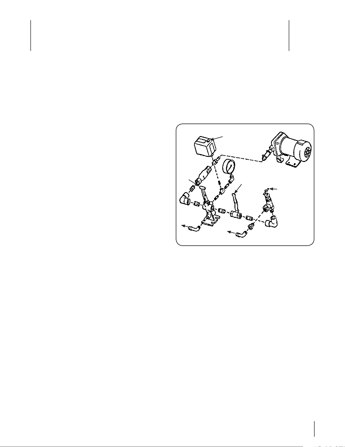
Demand Operation
Close the ball valve which stops all flow to the agitator, 1.
push the handle on the directo valve down which permits
flow to the spray wand and turn on the pump switch. See
Fig. 5-1.
This will force all of the flow from the pump to go to the 2.
spray wand. The pump will operate for a short period to
fill the hose to the spray wand and then will shut off. With
the valves in this position, the pump will turn on when the
spray wand is turned on and will shut off when the spray
wand is turned off.
Note: If you are using a 1.5 GPM spray tip, the pump will
turn on and off as you spray because the pump can output
4.8 GPM.
The pressure gauge should show no more than 45 psi when 3.
the spray wand is off. This is controlled by the pressure
switch which is preset at the factory. See Fig. 5-1.
Pressure greater than 45 psi will activate an internal circuit 4.
breaker in the pump, stopping it but it will start again in
about two minutes. If this repeats, you will have to adjust
the pressure switch.
To adjust the pressure switch, remove the cover from the 5.
switch and adjust the nut holding the small spring on the
right side up for a lower pump turnoff pressure (or down
for a higher pump turnoff pressure). The pump should
turn on when the pressure drops to 25 psi. Adjust the nut
holding the large spring in the center up for a lower turn-
on pressure or down for a higher turn-on pressure.
To Spray
Wand
To Agitator
Pressure
Regulator
Pressure Switch
Ball Valve
Directo
Valve
Figure 5-1

12 se c t i O n 5— Op e r a t i O n
Replace the pressure switch cover.6.
After the pressure switch is properly adjusted, check the 7.
flow rate out of the spray wand with a calibrated container.
(See Calibration.) This is the maximum flow rate possible.
To reduce the flow rate, you must adjust the valves so that
the pump runs constantly.
Constant Operation
Open the ball valve which permits flow to the agitator, push
the handle on the directo valve down which permits flow to
the spray wand and turn on the pump switch. Now adjust the
pressure regulator until the desired flow rate out of the spray
wand is achieved. See Fig. 5-1.
Note: Do not thread the “T” handle of the regulator too far
clockwise or the pump will start to operate intermittently. For
maximum agitation, open the ball valve which permits flow
to the agitator, pull the handle on the directo valve up which
shuts off flow to the spray wand and turn the pressure regulator
handle counterclockwise to relieve all of the spring pressure in
the regulator and provide maximum flow to the agitator.
Calibration
Hand Spraying
There are two keys to proper calibration of hand spraying. One is
knowing your spraying pace, that is, the time it consistently takes
you to spray an even application of product on each 1000 sq. ft.
area. The other is always knowing the current flow rate out of the
application device on your sprayer.
The first step is to set up your sprayer to spray two gallons per
minute. This is a common flow rate that can be used to check
your spraying pace. To do this, you need a graduated container.
Fill the sprayer tank one third full with clean water and 1.
start it up. Using the gun or wand that is mounted on your
sprayer, spray into the graduated container for one minute.
Check how much water you collected. 2.
Adjust the flow rate by adjusting the ball valve in the line to 3.
the agitator or the pressure regulator if necessary, until you
can collect two gallons in one minute.
The next step is to determine how long it takes you to evenly
spray 1000 sq. ft. Measure an area 20’ by 50’ on a paved surface.
Spray the area evenly with clean water. Use a stop watch to 1.
time your application. After the water evaporates, spray the
area again.
Repeat this several times and average the application 2.
times. Spraying on asphalt or concrete will permit you to
see the pattern you are applying and will give you a better
conception of even application.
Check the spray pattern as the water evaporates. Spraying 3.
technique is just as important as volume sprayed.
If your sprayer is set at a flow rate of two gallons per minute 4.
and your spraying pace is .75 minutes per 1000 sq. ft., you
are applying liquid at a rate of 1.5 gallons per 1000 sq.
ft. which is your application rate. (2 gallons/minute x .75
minutes/1 000 sq. ft. = 1.5 gallons/ 1000 sq. ft.).
It is wise to check the flow rate out of the application device
on your sprayer every working day. It is also wise to check your
spraying pace and the spraying pace of anyone else who will
be using the sprayer every month or so because as you can see,
the amount of liquid you apply depends on the flow rate of your
sprayer and your spraying pace. You can check your spraying
pace on every lawn you spray if you have measured the lawn
accurately.
The use of a Electronic Digital Flow Meter will permit you to very
accurately measure the flow rate and the total gallons of liquid
sprayed on each lawn. Your tank has gallonage markers which
may also be used to approximate the gallons of liquid that you
spray on each lawn. This figure should equal your application
rate times the number of 1000 sq. ft. in the lawn.
example: You have sprayed a 10,000 sq. ft. lawn at an
application rate of 1.5 gallons/1000 sq. ft. you should have
used 15 gallons. A flow meter should read 15 gallons. When
you started there were 180 gallons of liquid in your tank.
Now there should be 165 gallons left in the tank.
Adding Products to the Tank
CAUTION: avoid accidents. For safety, read the
entire product label including precautionary
statements. Use all products only as directed.
The product label will tell you how much product should be used
per 1000 sq. ft. If the label says you are to use 1.4 ounces per 1000
sq. ft. you divide the number of gallons of water in the tank by
your application rate (gallons per 1000 sq. ft.) and multiply by the
number of ounces of product per 1000 sq. ft.
example: 200 gallons divided by 1.5 gallons/1000 sq. ft.
times 1.4 ounces/1000 sq. ft. 186.6 ounces = 11.6 pints.
You would fill the sprayer tank one third full with clean water and
then add 11.6 pints of product to the tank through the strainer
basket while the sprayer is running under full agitation. After
the product is completely mixed, you would fill the tank to the
proper level with clean water.
Boom Spraying
There are two keys to proper calibration of boom spraying. One
is knowing and controlling the sprayers speed over the ground
and the other is always knowing the flow rate of the spray tips on
the boom. The following is a simplified procedure:
Measure and mark off a distance of 205 feet in an area that 1.
best represents the average topography for the area to
be sprayed. Select a safe tractor (truckster) speed (usually
three to six MPH) which can be maintained while spraying.
Write down the engine’s RPM and the gear selection so
that this speed can be maintained during both calibration
and actual spraying.
With the tractor (truckster) traveling at the selected speed 2.
and with the sprayer one half full of water, time and record
the seconds taken to travel the 205 feet.

13se c t i O n 5 — Op e r a t i O n
With the sprayer still half full of water, start the sprayer’s 3.
engine and adjust the pump’s pressure regulator to the
desired liquid pressure (normally between 20 and 50 psi).
Collect all the water from one nozzle for the same number
of seconds taken to travel the 205 feet.
example: If it took 35 seconds to travel the 205 feet, collect
the discharge of one nozzle for 35 seconds.
Boom with 20” nozzle spacing•
The number of fluid ounces collected equals the gallons
per acre (GPA) output.
Boom with 10” nozzle spacing•
Two times the number of fluid ounces collected equals the
gallons per acre (GPA) output.
Repeat this procedure two more times, collecting water 4.
from a different nozzle each time. Use the average number
of ounces collected from the three nozzles to determine
the gallons per acre output of the boom at the set pressure
and selected RPM and gear setting.
Note: If the ounces collected from any nozzle are 10%
greater or less then the ounces collected from any other
nozzle, it is a sign of wear and all the tips on the boom
should be replaced.
To determine the amount of product to add to the spray 5.
tank, divide the capacity of the tank by the number of
gallons of water per acre (GPA) to determine the area, in
acres, that can be covered with a tankful of spray.
example: 200 Gallon Tank divided by 20 GPA = 10 acres
covered per tankful.
Multiply the application rate of the product per acre times 6.
the acres per tankful and add that amount of product to
the tank through the strainer basket. The tank should be
one third filled with clean water with the sprayer running
under full agitation. After the product is completely mixed,
you would fill the tank to the proper level with clean water.
example: 2 quarts per acre x 10 acres per tankful = 20
quarts or 5 gallons of product to be added per tankful of
clean water.
To decrease the output adjust the pressure regulator to 7.
a lower pressure that still maintains the spray pattern; or
increase the speed of the tractor (truckster); or change the
nozzle tips to a smaller size.
To increase the output adjust the pressure regulator to a 8.
higher pressure that still maintains the spray pattern; or
decrease the speed of the tractor (truckster); or change the
nozzle tips to a larger size.
After changing output, recalibrate the sprayer.9.
Spraying Tips
Mixing Dry-Bagged Products for Sprayer Use
Dry-bagged products should be pre-mixed with clean water in
a five gallon container to form a slurry. The sprayer should be
one third filled with clean water and running under full agitation.
The slurry should be slowly poured into the sprayer through the
strainer basket. After the product is completely mixed, you would
fill the tank to the proper level with clean water.
Using the Gun
The flow rate is controlled by the nozzle selection, the trigger
position and the sprayer’s pump pressure. The gun’s trigger is
normally held full on and there is a trigger lock to hold it in this
position. However, releasing the trigger slightly will narrow the
pattern when spraying around trees and ornamentals. Each of
the nozzles throws a full cone pattern about five feet in diameter
with a droplet size large enough to help avoid drift yet small
enough for good penetration and thorough coverage.
Determine the application rate in gallons per 1000 sq. ft. from the
product label. Divide this figure by your spraying pace in minutes
per 1000 sq. ft. to determine the proper flow rate for the gun in
gallons per minute. Use this figure to select the proper nozzle and
then calibrate the sprayer, to spray this flow rate. To use the gun,
hold it in your right hand (if you are right handed) with the hose
forming a loop, running under your right arm to your back, over
your left shoulder, down across your chest and around and out from
your right side and back to the sprayer. Holding the hose in this way
takes the weight of the hose off of your right arm and allows you to
pull the hose with your whole body and not just your arm.
If you are left handed, the above would be reversed. Swing the
gun with your wrist so that the pattern is in constant motion and
covers a swath about eight feet wide. Start at the sprayer and work
into the lawn. Walk in parallel paths about eight feet apart and
make sure your spray pattern slightly overlaps the previous pass.
Keep the spray pattern away from ornamentals, trees and gardens.
Using the Spray Wand
The Spray Wand consists of a ball valve which controls the width of
the pattern, a handle, a trigger valve which turn’s the flow on and
off, an extension, a screen strainer, a hex chamber which controls
the flow to the tip, one of two brass tips and a nut to hold the tip in
place. The low volume tip discharges about 1-1⁄4 gallons per minute
and the high volume tip discharges about 1-1⁄2 gallons per minute.
The tips throw the best pattern at a pump pressure of about 40 psi.
Both tips throw a fan shaped pattern about eight feet wide with a
droplet size large enough to help avoid drift.
Determine the application rate in gallons per 1000 sq. ft. from the
product label. Divide this figure by your spraying pace in minutes
per 1000 sq. ft. to determine the proper flow rate for the wand
in gallons per minute. Use this figure to select the proper tip and
then calibrate the sprayer to spray this flow rate.
To use the wand, hold it in your hand with the hose running
around your body as described in the section on the Gun. Hold
the wand so that the tip is 18 to 24 inches above the ground and
the spray pattern covers a swath about eight feet wide. Hold the
wand steady and lock the trigger on. Start at the sprayer and
work into the lawn. Walk in parallel paths about eight feet apart
and make sure your spray pattern slightly overlaps the previous
pass. Use the ball valve to control the pattern width to keep the
spray pattern away from ornamentals, trees and gardens.

14 se c t i O n 5— Op e r a t i O n
Using High Pressure Guns
The 43H GunJets which will operate at pressures from 200-800 psi
and are available in brass or aluminum are recommended. When
equipped with an Orifice Disc No. D6, at 400 psi, they will spray 4.1
gallons per minute a maximum horizontal distance of 48’. They
have a trigger handle control and as the trigger is drawn back, the
valve moves from shut off position to initial wide angle cone spray
to continuously narrower cone sprays to a final straight stream.
A ridged nut behind the trigger can be threaded in or out to stop
the trigger at any desired position. There Is also a trigger lock
that can be used to hold the trigger in the “On” position.
43H-D6 Brass GunJet Spray Gun, 200-800 psi•
43H-AL-D6 Aluminum GunJet Spray Gun, 200-800 psi•
These spray guns are used for spraying small trees, orchard and
nursery spraying and cleaning decks, patios, brick, aluminum
siding, concrete driveways, vehicles and equipment.
When spraying small trees (up to 30’) and shrubs, use a spreader-
sticker except when applying a dormant oil. Use a pressure of
200-300 psi and spray only until the material starts dripping, no
more is necessary. All runoff is wasted. Alternate insecticides when
spraying during the growing season. Landscape (foliage) area
can be measured in square footage. Spray volume necessary for
coverage is usually around 10 gallons per 1000 sq. ft. of foliage.
Cleaning the Sprayer
After use, flush the sprayer tank, and the entire system, pump,
plumbing, hoses and gun, wand or boom to neutralize chemicals
and reduce pump problems. Follow the instructions on the label.
Extra cleaning care should be taken after spraying herbicides to
prevent possible damage to turf or plants when next spraying
insecticides or fungicides. After the sprayer has been flushed,
clean the in-line strainer. Hose off the outside of the sprayer to
wash off dust and dirt. Do not spray water on the engine if it is hot.

Maintenance & Adjustments
6
15
Engine
Refer to the Engine Operators manual packed separately with your
sprayer for maintenance and adjustment information for your engine.
Battery
DANGER! Always wear safety glasses and rubber
gloves when working on the battery. Keep sparks
and flames away at all times.
The battery used on electric sprayers and to operate the reel on
other sprayers should be maintained as follows:
Remove the fillcaps and check the level of the liquid 1.
electrolyte in the battery every 50 operating hours. If the
level in any of the six cells has dropped below the bottom
of the split ring inside the fill hole, refill the cell with
distilled water. DO NOT OVERFILL THE BATTERY.
To keep the outside of the battery clean, brush on a strong 2.
solution of bicarbonate of soda and water and rinse with
clean water.
Keep the contacts and cable ends clean with a wire 3.
brush and make sure the connections are tight. Coat the
terminals with petroleum jelly to prevent corrosion.
Pump
Diaphragm pumps require very little maintenance. The
procedures that are required are listed in the pump Installation/
Operation instructions furnished with the sprayer.
Daily Checks
Check the oil level.•
Make certain there are no kinks in the suction line and that •
the suction line connections are tight.
Check the air pressure in the pulsation damper. It should be •
at least 10-percent of the expected operating pressure.
After use, flush out the pump. See the section on Cleaning •
the Sprayer.
Every 200-Hours and at the End of Each Spray Season:
Change the oil.•
At the End of Each Spray Season:
Change the diaphragms. See the Service section.•
Agitator
Most of the fiberglass sprayers have mechanical agitation and
the agitator grease fittings on the front and rear of the tank
should be greased after each 8 hours of operation. The two
agitation packing gland nuts on the front of the tank, behind the
belt guard, should be tightened as needed to eliminate dripping.
Tighten the adjusting nuts equally, 90° at a time, to compress
the packing evenly until the dripping is stopped. Replace the
packing when dripping cannot be stopped.
Tank
The sprayer tank requires no scheduled maintenance. The inside
of the tank should be flushed out after each use as described
in the section on Cleaning the Sprayer. The outside of the
tank should be hosed off after use and scrubbed occasionally
with soapy water to remove ground-in dirt. If the tank is ever
accidentally punctured, it can be repaired with a Poly Patch Kit.
In-Line Strainer
The in-line strainer should be cleaned each day after the sprayer
has been flushed. Place a flat pan under the strainer bowl to
catch the liquid and unscrew the bowl.
Note: There is a washer-like seal between the top lip of the bowl
and the strainer body. This seal will sometimes come off on top
of the bowl or will drop out of the strainer body when the bowl is
unscrewed. DO NOT LOSE THIS SEAL! It must be installed or you
won’t be able to operate your sprayer.
Hose
If the hose on your sprayer is treated carefully, it will give long and
trouble free service. When you have finished spraying a lawn, carry
the application device and drag the hose back to the sprayer. This
protects the application device from being damaged by being
dragged through the turf and permits you to insure, as you walk
back to the sprayer, that the hose is not snagged on something or
wrapped around a tree. It also eases the load on your reel because
the hose will be rewound from only half the distance. The hose
should be flushed out daily as described in the section on Cleaning
the Sprayer. Weekly, you should clean off the outside cover of the
hose by rewinding it onto the reel while gripping it lightly with a
rag dipped in soapy water.
Off-Season Storage
If the sprayer will not be used for 30 days or more it should be
thoroughly flushed out and cleaned as described in the section
on Cleaning the Sprayer.
Change the oil in the pump every 200 hours and at the end 1.
of the spraying season.
Change the pump’s diaphragms at the end of each 2.
spraying season.
The sprayer should be stored in a clean, dry area which 3.
should be heated if freezing weather will occur during the
time of storage. If storing in a heated room is not possible,
winterize the sprayer.
Pour a gallon of antifreeze and a gallon of clean a.
water into the sprayer.
Start the engine and agitate the mixture.b.
Then pump the antifreeze mixture through the c.
plumbing and discharge it from the application
device back into two one gallon containers.
Store the 50/50 antifreeze mixture for future use. d.
If a boom is your application device, spray a small e.
amount of the antifreeze mixture from the boom and
then shut it off and drain the rest of the mixture from
the tank using the drain on the front of the sprayer.

Service
7
16
Changing the Diaphragms
To change the diaphragms, you need a set of metric wrenches
and a set of metric allen wrenches.
Drain the oil from the crankcase. The larger pumps have 1.
a drain plug for this purpose. The smaller pumps must be
removed from the sprayer, the oil cap removed and the
pump turned upside down to drain the oil. Rotate the shaft
until all the oil is drained.
Remove the manifold nuts and the head nuts. Work on 2.
one head at a time. Remove the manifold and the head.
Remove the diaphragm nut, the retaining washer and the
diaphragm.
Turn the crankshaft to bring the piston to its downstroke 3.
and seat the new diaphragm into the sleeve groove.
Replace the retaining washer and tighten the diaphragm 4.
nut. Reinstall the head.
Replace the other head diaphragms and then replace the 5.
manifold.
Pulsation Damper Diaphragm
To replace the pulsation damper diaphragm, bleed the air 1.
from the damper.
Remove the bolts holding the damper assembly together. 2.
Replace the diaphragm and replace the bolts. 3.
Recharge the damper with air pressure to 10% of the 4.
expected operating pressure.
Remount the pump on the sprayer and refill the crankcase 5.
with oil.

Troubleshooting
8
17
Problem Cause Remedy
Pump does not draw water The in-line strainer is clogged1.
The suction line is plugged or collapsed2.
Gate valve in suction line is closed3.
One or more valves are seating improperly4.
Clean the in-line strainer1.
Examine the suction line2.
Open gate valve3.
Examine the valve seatings and clean them 4.
or replace if scored or worn
Oil comes out of the
discharge port
One or more diaphragms are split1. Drain the pump of oil. Dismantle the heads 1.
and replace the diaphragms. Refill the pump
with fresh oil
The pressure gauge
fluctuates excessively
The pump is sucking in air somewhere in the 1.
suction line
Air has not been entirely evacuated from the 2.
pump
Examine the suction line and make certain all 1.
parts are firmly secured
Run the pump with the outlet hose open to 2.
evacuate air from the pump
The liquid flow is irregular Incorrect charge In the pulsation damper 1.
One or more valves are seating improperly2.
Check the charge in the pulsation damper. 3.
(10% of working pressure)
Examine the valve seatings and clean them 4.
or replace them if scored or worn
The output drops and the
pump is noisy
The oil level is too low1. Add oil to the correct level for the pump1.
No agitation Fiberglass sprayer — The agitator belt is 1.
loose.
Poly sprayer — The ball valve to the agitator 2.
is shut off or the line is plugged.
Tighten the agitator belt. 1.
Open the ball valve to the agitator. Check the 2.
line to the agitator.

Attachments & Accessories
9
18
Part Part No.
00024132 Hose Assembly, Pump-to-Hose Reel
00033030 100’, 3/8” dia., 300-psi working pressure, PVC Spray Hose
00033040 200’, 3/8” dia., 300-psi working pressure, PVC Spray Hose
00033050 300’, 3/8” dia., 300-psi working pressure, PVC Spray Hose
00010856 Spray Wand, 5-quarts/minute
00005419 Spray Wand, 6-quarts/minute
The following attachments and accessories are compatible for Cub Cadet Commercial 50, 100, 200, 300 Gallon Sprayers and 200
Gallon Compact Sprayer. See your Cub Cadet Commercial dealer from which you purchased your sprayer for information regarding
price and availability.
50 Gallon Sprayer
Part Part No.
00004600 * Walking Boom, 8-8008 SS Nozzles on 10” Center
00017302 Hose Assembly, Pump-to-Reel
00020197 400’-3/8” I.D., 600 psi, 3/4” GHT Couplings
00020201 100’-1/2” I.D., 800 psi, 3/4” GHT Couplings
00020198 200’-1/2” I.D., 800 psi, 3/4” GHT Couplings
00020199 300’-1/2” I.D., 800 psi, 3/4” GHT Couplings
00009134 1” I.D., Spiraflex. (Sold per foot)
00005419 6 quarts/minute
100/200/300 Gallon Sprayer & 200 Gallon Compact Sprayer
* — Not available for 300 gallon sprayer
Illustrated Parts List
10
19
13
13
13
23
22
24
22
6
22
8
15
3
14
22
20
4
2
22
22
9
7
9
1
16
1
18
10
4
17
7
25
12
5
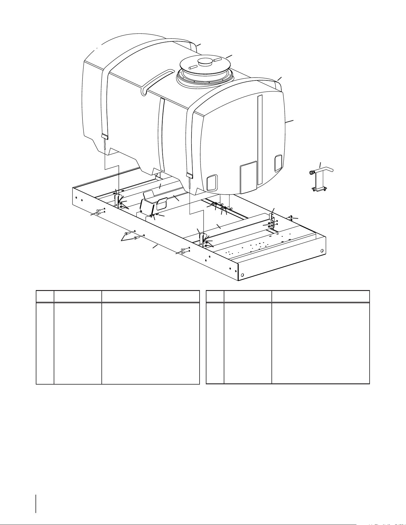
Ref.
Part Number Description
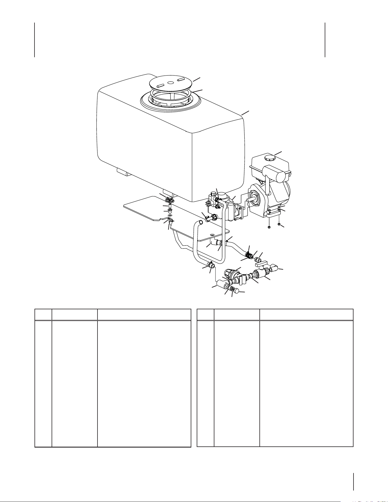
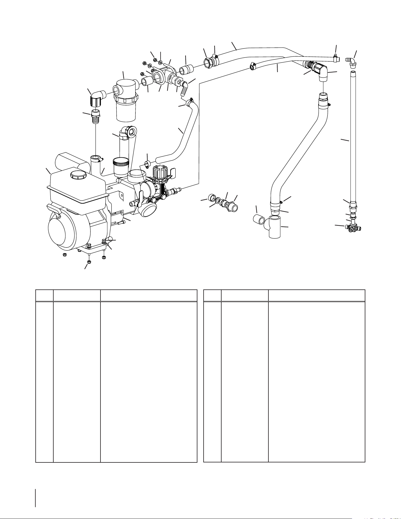
1 00002406 Nipple, 3⁄4
2 00003011 Insulated Male Adapter, 3⁄4
3 00005610 Jet Agitator
4 00006017 Elbow, 3⁄4
5 00006129 Hex Screw, 5⁄16-18 x 1.75
6 00006145 90° Elbow, 1⁄2 x 1⁄2
7 00006303 Threaded Pipe Hose, 3⁄4 x 3⁄4
8 00006430 Reducer Bushing, 1⁄2 x 1⁄4
9 00007595 Hose Washer, 3⁄4
10 00007687 Brass Female Hose, 3⁄4
11 00008295 Hose, 1⁄2
12 00009812 Washer, .344 x .688 x .063
13 00010033 50 Gallon Poly Tank
Ref.
Part Number Description
14 00011233 Strainer, 3⁄4
15 00011939 Brass Nipple, 1⁄4
16 00012664 Brass Hose Cap, 3⁄4
17 00016465 PVC Tee, 3⁄4
18 00019013 PVC Ball Valve, 3⁄4
19 00030918 Reinforced Hose, 5⁄8
20 00031785 Fitting, 3⁄4 x 5⁄8
21 00033300 Spiraex Hose, 3⁄4
22 01000216 Hose Clamp
23 01001000 Kawasaki Engine
24 01005668 Hypro Pump
25 912-0429 Hex Lock Nut, 5⁄16-18
NS 01005577 Adapter, 3⁄4 x 3⁄4
50 Gallon Pump, Tank &
Engine Assembly
20 se c t i O n 10 — il l u s t r a t e d pa r t s li s t
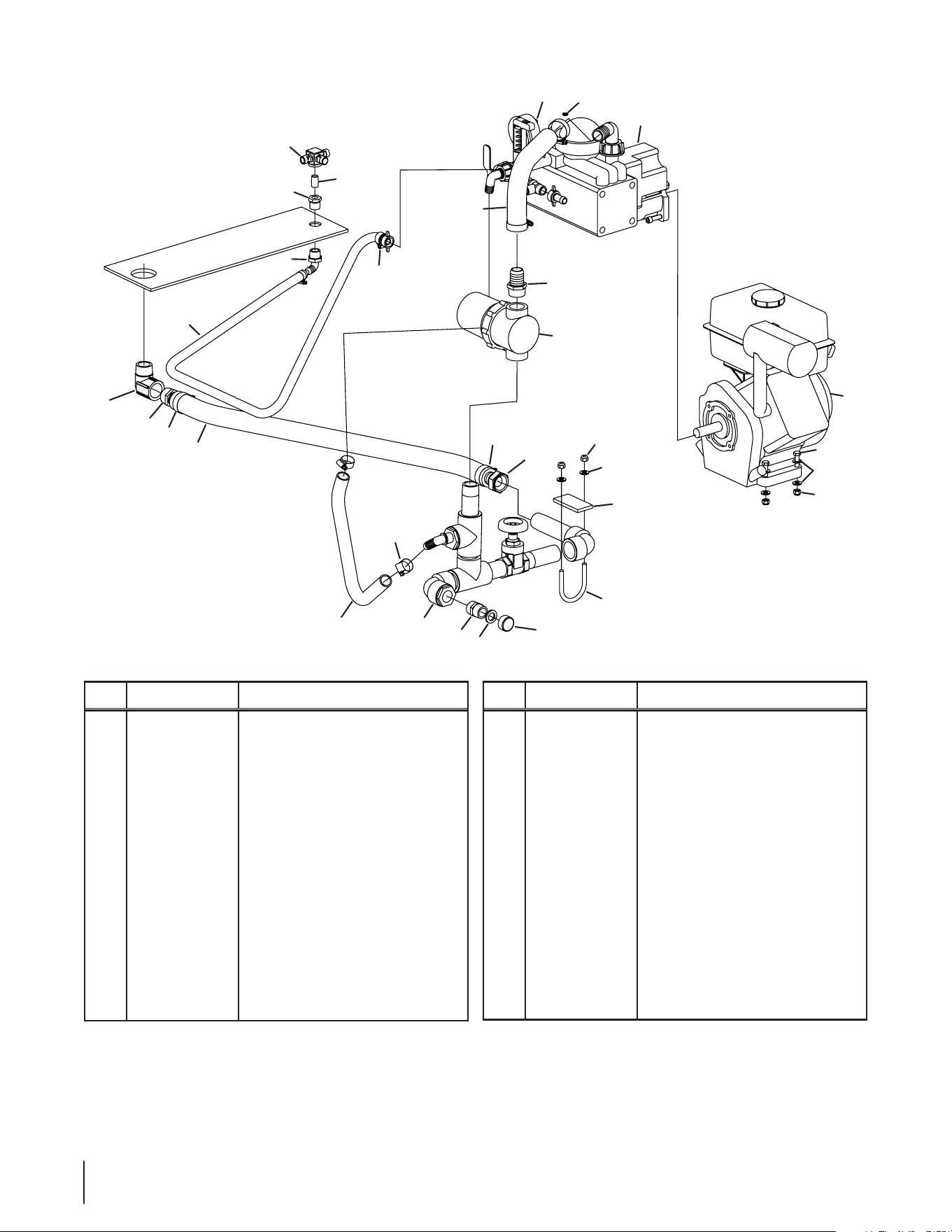
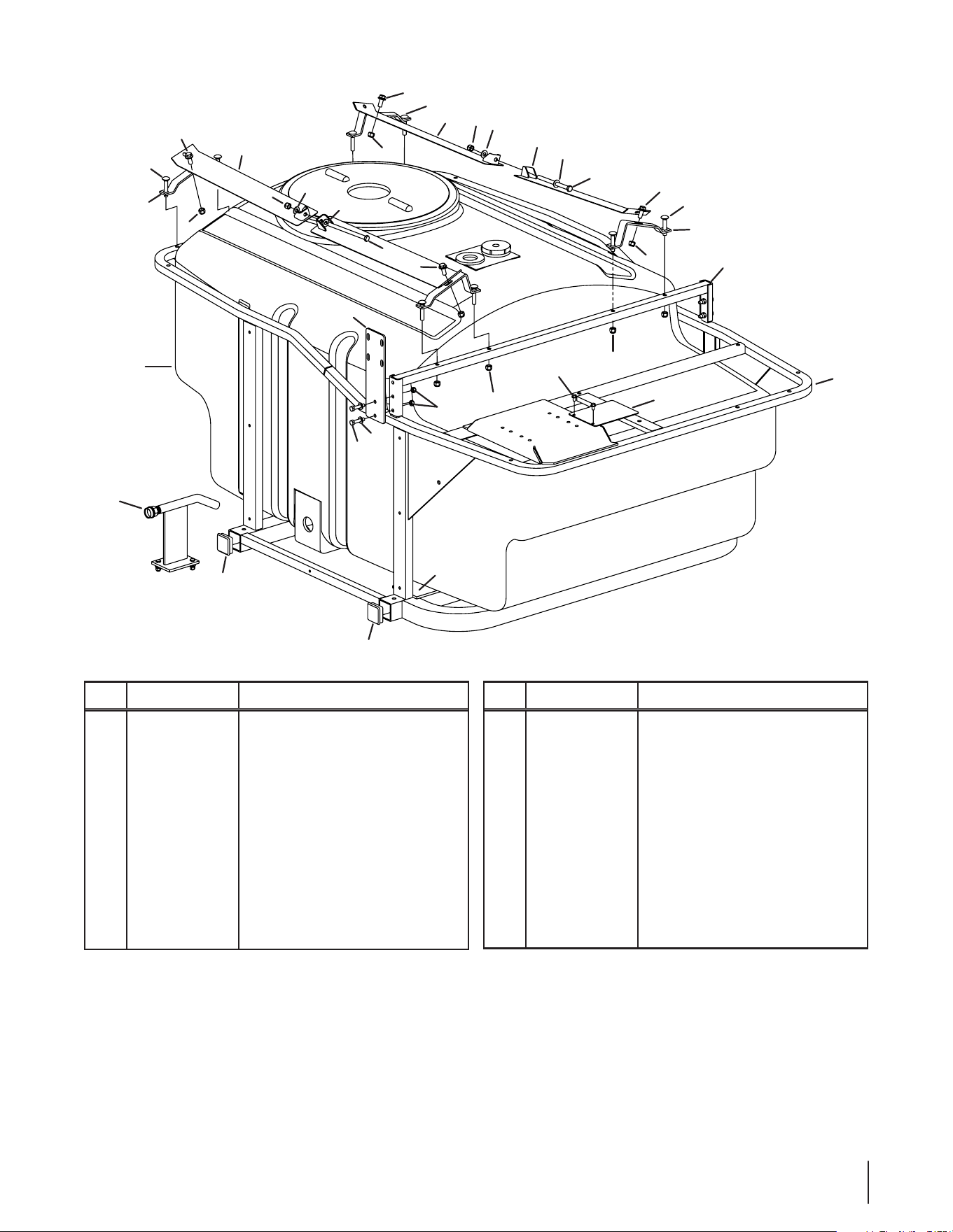
Ref.
Part Number Description
1 00005610 Jet Agitator
2 00006129 Hex Screw, 5⁄16-18 x 1.75
3 00006145 90° Elbow, 1⁄2 x 1⁄2
4 00006303 Threaded Pipe Hose, 3/4 x 3/4
5 00006416 Insulated Male Hose, 1 x 1
6 00006430 Reducer Bushing, 1⁄2 x 1⁄4
7 00007595 Hose Washer, 3⁄4
8 00007713 Female Hose Repair End, 1
9 00008295 Hose, 1⁄2
10 00009134 Spiraex Hose, 1
11 00009670 Carriage Bolt, 5⁄16-18 x 2.62 x 2.30
12 00009812 Washer, .344 x .688 x .063
13 00011021 Manifold Assembly, 100/200/300
Ref.
Part Number Description
14 00011939 Brass Nipple, 1⁄4
15 00012038 Rubber Pad, 1⁄4 x 1-1⁄2 x 3
16 00012664 Brass Hose Cap, 3⁄4
17 00030918 Reinforced Hose, 5⁄8
18 00070471 Elbow, 1 x 90
19 01000210 Pump Assembly
20 01000216 Hose Clamp
21 01000217 Hose Clamp
22 01001001P Kawasaki Engine
23 01004380 Mesh Bowl Strainer
24 912- 0429 Hex Lock Nut, 5⁄16-18
NS 01005577 Adapter, 3⁄4 x 3⁄4
1
3
6
20
14
18
5
21
10
9
17
4
7
13
16
20
8
21
11
15
12
24
24
22
2
12
10
19
24
24
5
23
100/200 Gallon Pump &
Engine Assembly
21se c t i O n 10 — il l u s t r a t e d pa r t s li s t
19
9
19
17
22
5
20
23
10
5
20
18
3
6
14
1
12
15
11
7
16
4
13
24
8
20
12
24
12
2
21
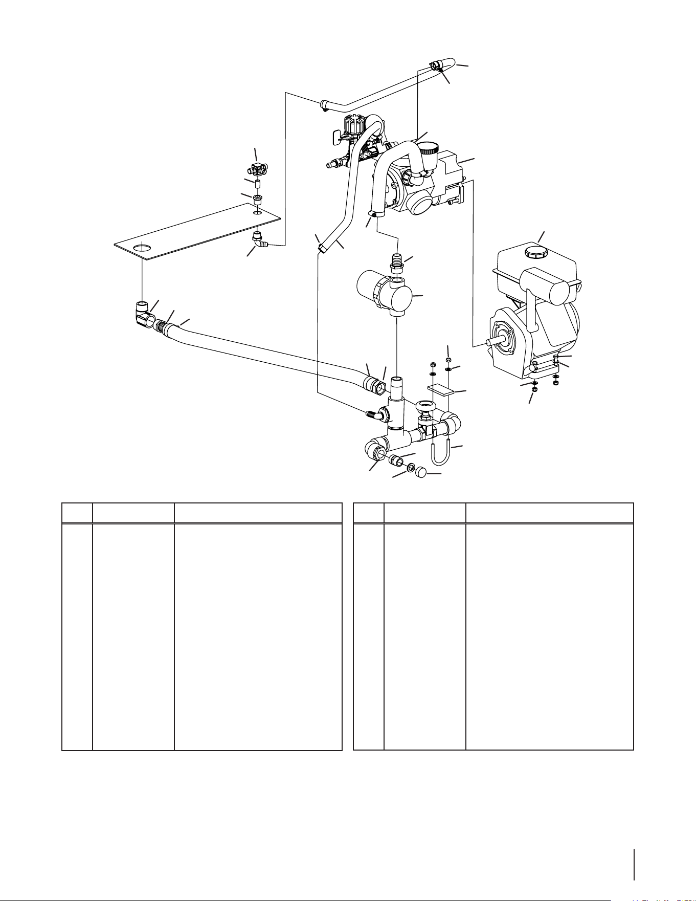
300 Gallon Pump &
Engine Assembly
Ref.
Part Number Description
1 00005610 Jet Agitator
2 00006129 Hex Screw, 5⁄16-18 x 1.75
3 00006145 90° Elbow, 1⁄2 x 1⁄2
4 00006303 Threaded Pipe Hose, 3/4 x 3/4
5 00006416 Insulated Male Hose, 1 x 1
6 00006430 Reducer Bushing, 1⁄2 x 1⁄4
7 00007595 Hose Washer, 3⁄4
8 00007713 Female Hose Repair End, 1
9 00008295 Hose, 1⁄2
10 00009134 Spiraex Hose, 1
11 00009670 Carriage Bolt, 5⁄16-18 x 2.62 x 2.30
12 00009812 Washer, .344 x .688 x .063
13 00011021 Manifold Assembly, 100/200/300
Ref.
Part Number Description
14 00011939 Brass Nipple, 1⁄4
15 00012038 Rubber Pad, 1⁄4 x 1-1⁄2 x 3
16 00012664 Brass Hose Cap, 3⁄4
17 00030918 Reinforced Hose, 5⁄8
18 00070471 Elbow, 1 x 90
19 01000216 Hose Clamp
20 01000217 Hose Clamp
21 01001001P Kawasaki Engine
22 01004380 Mesh Bowl Strainer
23 01005827P Hypro Pump
24 912- 0429 Hex Lock Nut, 5⁄16-18
NS 01005577 Adapter, 3⁄4 x 3⁄4
22 se c t i O n 10 — il l u s t r a t e d pa r t s li s t
24
10
22
8
13
25
15
14
22
24
27
1
19
31
17
23
4
16
16
3
2
26
25
15
10
24
7
17
30
31
21
9
12
5
20
23
10
25
1
18
6
11
29
28
200 Gallon Compact
Pump & Engine Assembly
Ref.
Part Number Description
1 00002108 Nipple, 1”
2 00002121 Nipple, 1"
3 00002909 Insulated Elbow, 1⁄2
4 00003241 PVC Bushing, 1 x 1/2
5 00003254 PVC Bushing, 1 x 3⁄4
6 00005610 Jet Agitator
7 00006129 Hex Screw, 5⁄16-18 x 1.75
8 00006145 90° Elbow, 1⁄2 x 1⁄2
9 00006303 Threaded Pip Hose, 3⁄4 x 3⁄4
10 00006416 Insulated Male Hose, 1 x 1
11 00006430 Reducer Bushing, 1⁄2 x 1⁄4
12 00007595 Hose Washer, 3⁄4
13 00007713 Female Hose Repair End, 1
14 00008295 Hose, 1⁄2
15 00009134 Spiraex Hose, 1
16 00009670 Carriage Bolt, 5⁄16-18 x 2.62 x 2.30
Ref.
Part Number Description
17 00009812 Washer, .344 x .688 x .063
18 00011939 Brass Nipple, 1⁄4
19 00012038 Rubber Pad, 1⁄4 x 1-1⁄2 x 3
20 00012664 Brass Hose Cap, 3⁄4
21 00030918 Reinforced Hose, 5⁄8
22 00070471 Elbow, 1 x 90
23 00070485 PVC Tee, 1
24 01000216 Hose Clamp
25 01000217 Hose Clamp
26 01001001P Kawasaki Engine
27 01004380 Mesh Bowl Strainer
28 01005199 Tank Pick-Up Agitator Tube
29 01005223 Coupling, 1⁄2
30 01005827P Hypro Pump
31 912- 0429 Hex Lock Nut, 5⁄16-18
NS 01005577 Adapter, 3⁄4 x 3⁄4
23se c t i O n 10 — il l u s t r a t e d pa r t s li s t
10
13
16
5
7
14
15
3
8
2
3
18
19
9
17
6
12
18
18
1
4
4
11
18
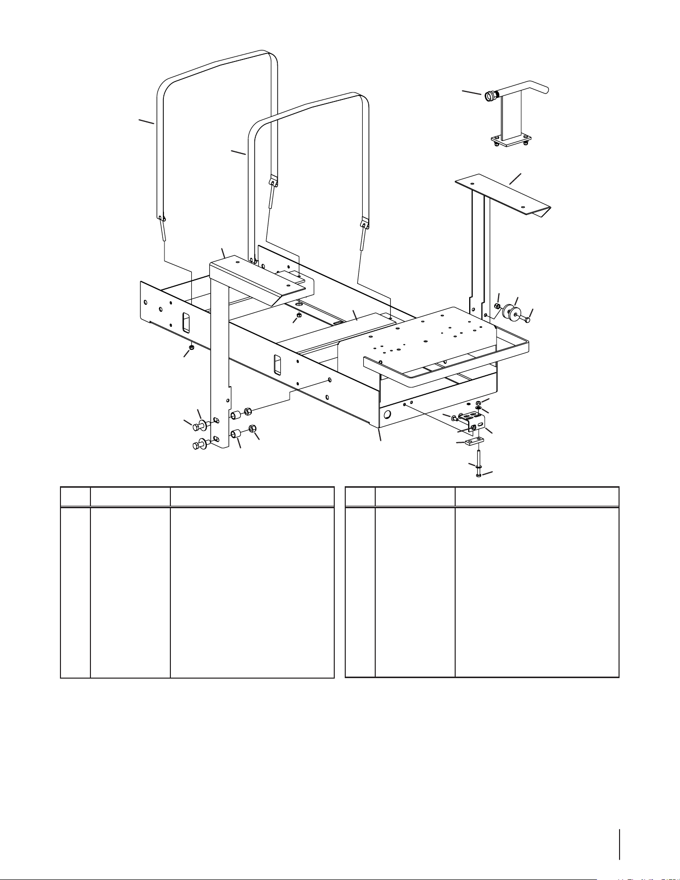
50 Gallon Frame
Assembly
Ref.
Part Number Description
1 00008382 Adhesive Backed Foam 4 x 1⁄4
2 00009015 Hex Screw, 5⁄16-18 x 3.25
3 00009812 Washer, .344 x .688 x .063
4 00010836 Tank Strap
5 00011444 Hex Screw, 3⁄8-16 x 1.25
6 00011459 Washer, .563 x 1.38 x .109
7 712- 04065 Lock Nut, 3⁄8-16
8 00020508 Carriage Bolt, 5⁄16-18 x .750
9 750-3065 Spacer, .635 x .875 x .860
10 01001047 Air Gap Filler
Ref.
Part Number Description
11 01002009 Main Frame
12 01002028 LH Reel Support Assembly
13 01002029 RH Reel Support Assembly
14 01002641 Mounting Bracket
15 01003525 Strainer Block Spacer
16 736-04131 Washer, .438 x 1.745 x .250
17 710-0489 Hex Screw, 1⁄2-13 x 2.00
18 912-0429 Hex Lock Nut, 5⁄16-18
19 712-3083 Hex Lock Nut, 1⁄2-13
24 se c t i O n 10 — il l u s t r a t e d pa r t s li s t
3
4
3
4
3
1
2
2
7
7
6
5
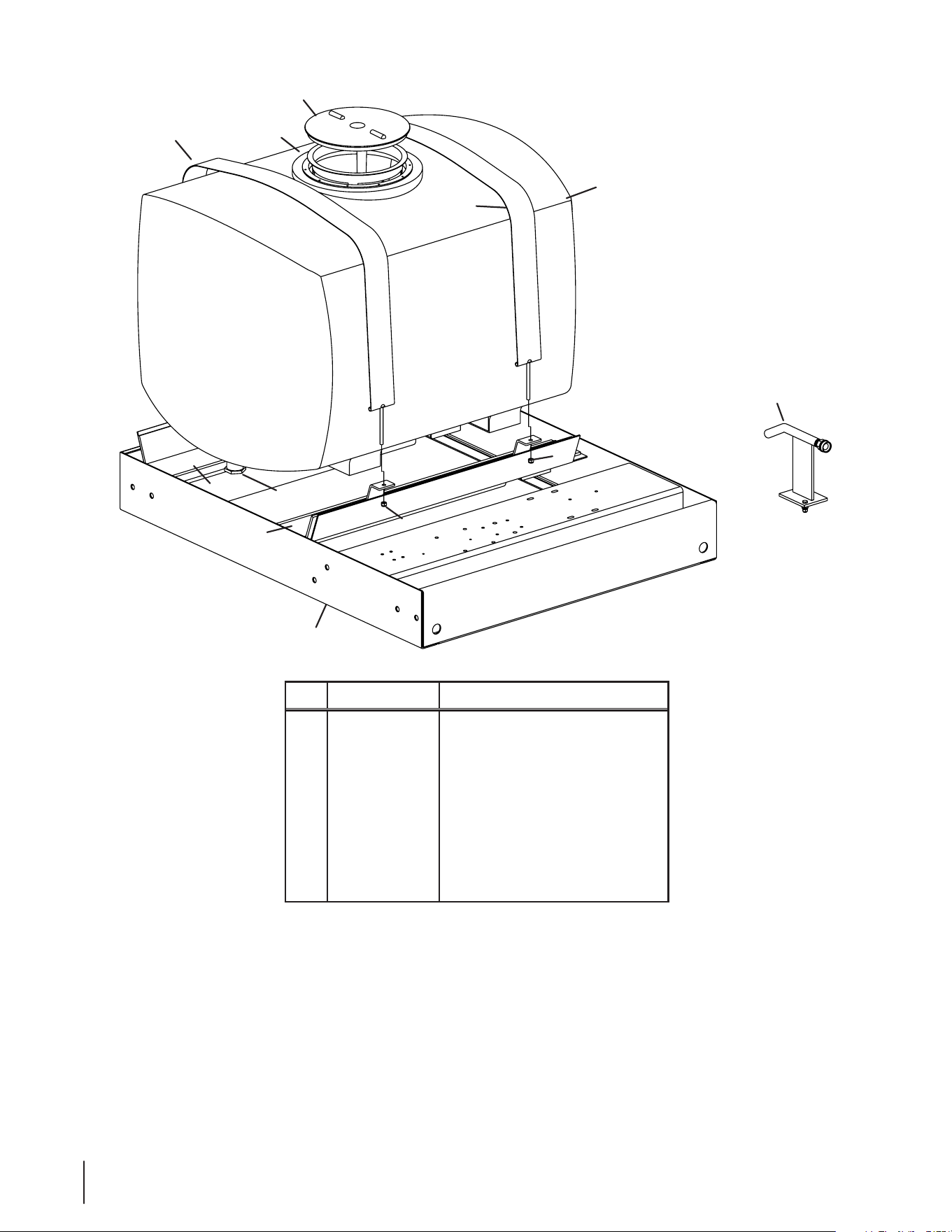
100 Gallon Frame
& Tank Assembly
Ref.
Part Number Description
1 00003293 PVC Adapter, 1.25 x 1
2 00008382 Adhesive Backed Foam, 1⁄4 x 4
3 00009359 100 Gallon Poly Tank
4 00014205 Tank Strap
5 01001047 Air Gap Filler
6 01003070 Main Frame
7 912- 0429 Hex Lock Nut, 5⁄16 -18
NS 00009134 Hose, 1-1⁄4
25se c t i O n 10 — il l u s t r a t e d pa r t s li s t
2
2
6
3
7
7
1
5
4
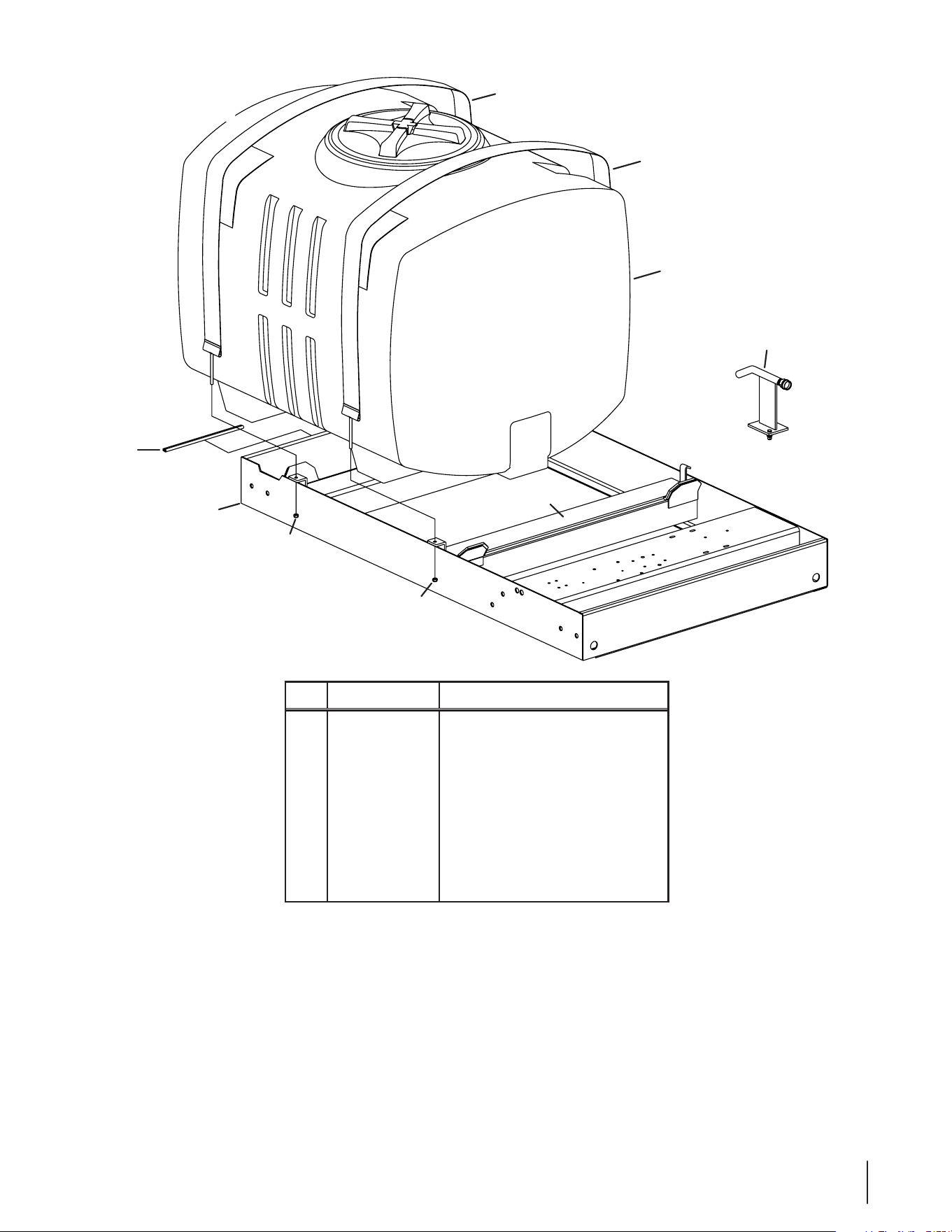
200 Gallon Frame
& Tank Assembly
Ref.
Part Number Description
1 00008382 Adhesive Backed Foam
2 00013315 Tank Strap
3 01001047 Air Gap Filler
4 01002046 Main Frame
5 735-04130 Edge Trim
6 631-04467 Tank Assembly
7 912- 0429 Hex Lock Nut, 5⁄16-18
NS 00009134 Hose, 1-1⁄4
26 se c t i O n 10 — il l u s t r a t e d pa r t s li s t
12
4
9
4
3
12
6
9
10
2
14
15
1
11
15
15
5
5
13
7
5
15
1
1
3
14
2
12
11
300 Gallon Frame
& Tank Assembly
Ref.
Part Number Description
1 00008382 Adhesive Backed Foam
2 00009812 Flat Washer, 5⁄16
3 712- 04065 Lock Nut, 3⁄8-16
4 00013315 Tank Strap
5 936-0160 Flat Washer, .536 x .930 x .05
6 01001047 Air Gap Filler
7 01001178 Main Frame
8 01006605 Center Support Bracket
Ref.
Part Number Description
9 01006622 300 Gallon Poly Tank
10 01006642 Strap Mounting Hook
11 01006653 Strap Mounting Bracket
12 710-3168 Carriage Bolt, 3⁄8-16 x 1.00
13 710-3181 Hex Screw, 1⁄2-13 x 1.50
14 912- 0429 Hex Lock Nut, 5⁄16-18
15 712-3083 Hex Lock Nut, 1⁄2-13
NS 00009134 Hose, 1-1⁄4
27se c t i O n 10 — il l u s t r a t e d pa r t s li s t
14
4
9
18
10
4
3
3
6
18
16
4
14
9
18
6
3
10
4
3
4
10
9
18
7
12
4
4
15
5
2
19
8
13
11
11
1
17
200 Gallon Compact
Frame & Tank Assembly
Ref.
Part Number Description
1 00008382 Adhesive Backed Foam
2 00009812 Washer, .344 x .688 x .063
3 00012158 Washer, .406 x .813 x .063
4 712- 04065 Lock Nut, 3⁄8-16
5 00012382 Hex Screw, 5⁄16-18 x 1.50
6 00035881 Hex Screw, 3⁄8-16 x 5.00
7 710-0599 Hex Flange Screw, 1⁄4-20 x .500
8 01001047 Air Gap Filler
9 01002011 Carriage Bolt, 3⁄8-16 x 2.0
10 01004536 Tank Strap
Ref.
Part Number Description
11 01005160 Square Tube Plug
12 01005185 Main Frame
13 01005222 Tank Assembly
14 01005335 Tank Strap Mount
15 01005506 Strainer Mount Bracket
16 01005543 Tank Strap Mount
17 01006351 Decal Plate
18 710-0514 Hex Screw, 3⁄8-16 x 1.00
19 912-0429 Hex Lock Nut, 5⁄16-18
28 se c t i O n 10 — il l u s t r a t e d pa r t s li s t
14
8
10
2
7
13
10
3
6
5
9
6
4
12
1
5
1
5
11
7
12
3
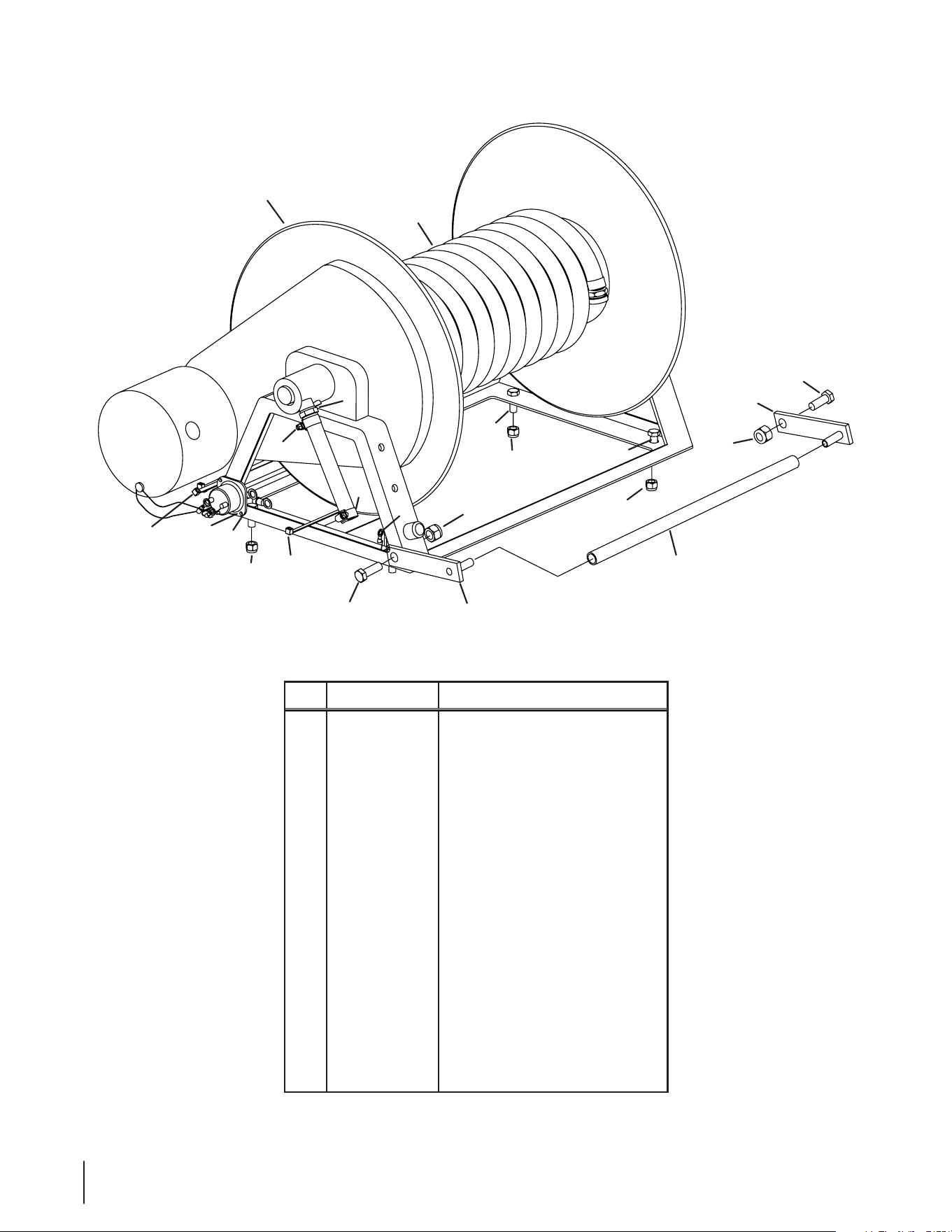
50 Gallon Hose Reel &
Mounting Assembly
Ref.
Part Number Description
1 00006144 Hex Screw, 3⁄8-16 x 1.00
2 00006442 Hose Barb, 1⁄2
3 00008724 Hex Screw, 7⁄16-14 x 1.00
4 00010628 Ring Terminal
5 712- 04065 Lock Nut, 3⁄8-16
6 725-0157 Cable Tie
7 712- 0290 Hex Lock Nut, 7⁄16-14
8 00033050 Hose Assembly, 3⁄8
9 00060033 Flat Washer, 1⁄4
10 01000215 Hose Clamp
11 02004733 Hose Guard
12 02004734 Hose Guard Mounting Assembly
13 01002319 Electric Wiring Harness
14 01002643 Hose Reel
NS 00010863 Electric Wiring Kit
29se c t i O n 10 — il l u s t r a t e d pa r t s li s t
12
7
10
16
5
11
5
15
15
11
18
9
9
18
4
17
18
5
17
14
4
18
8
1
6
8
2
3
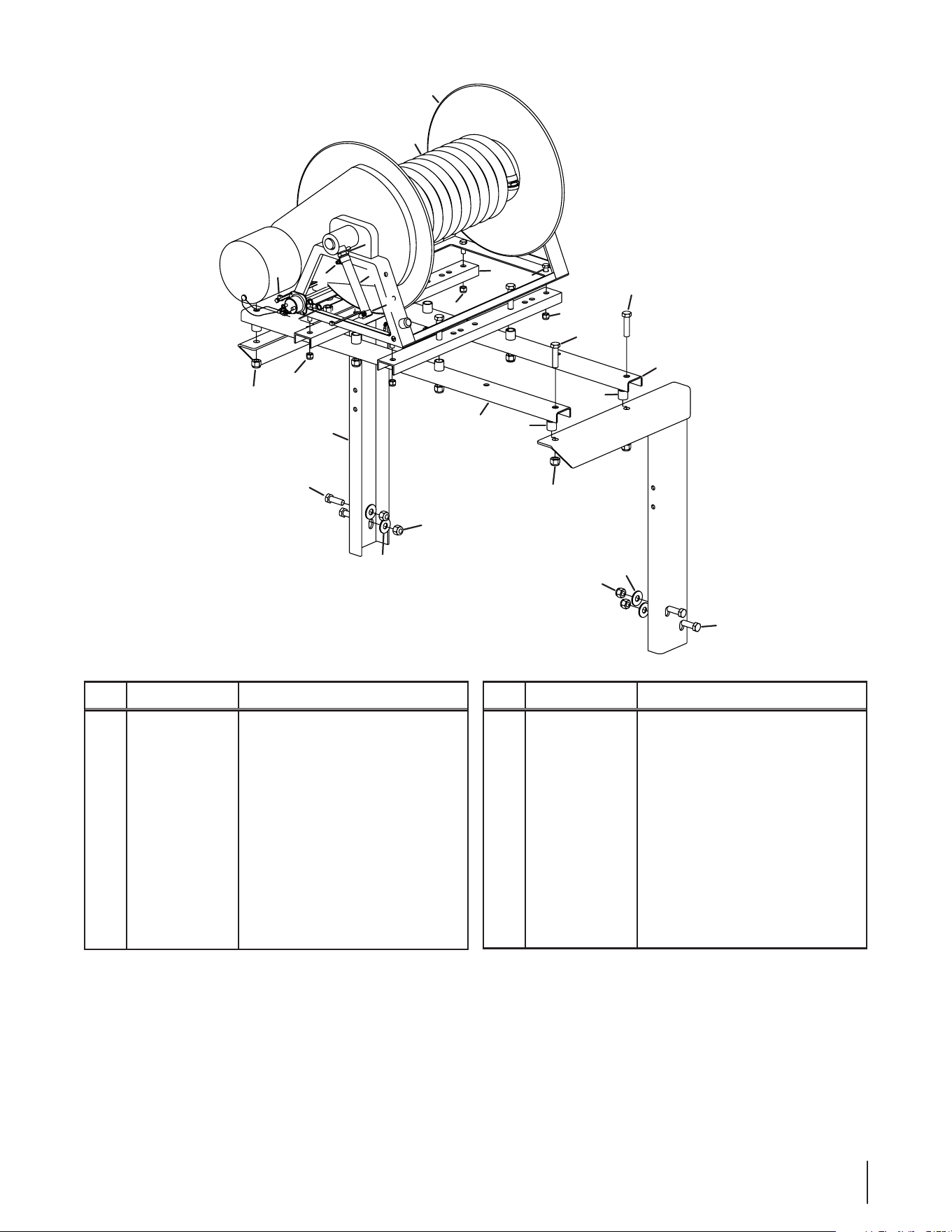
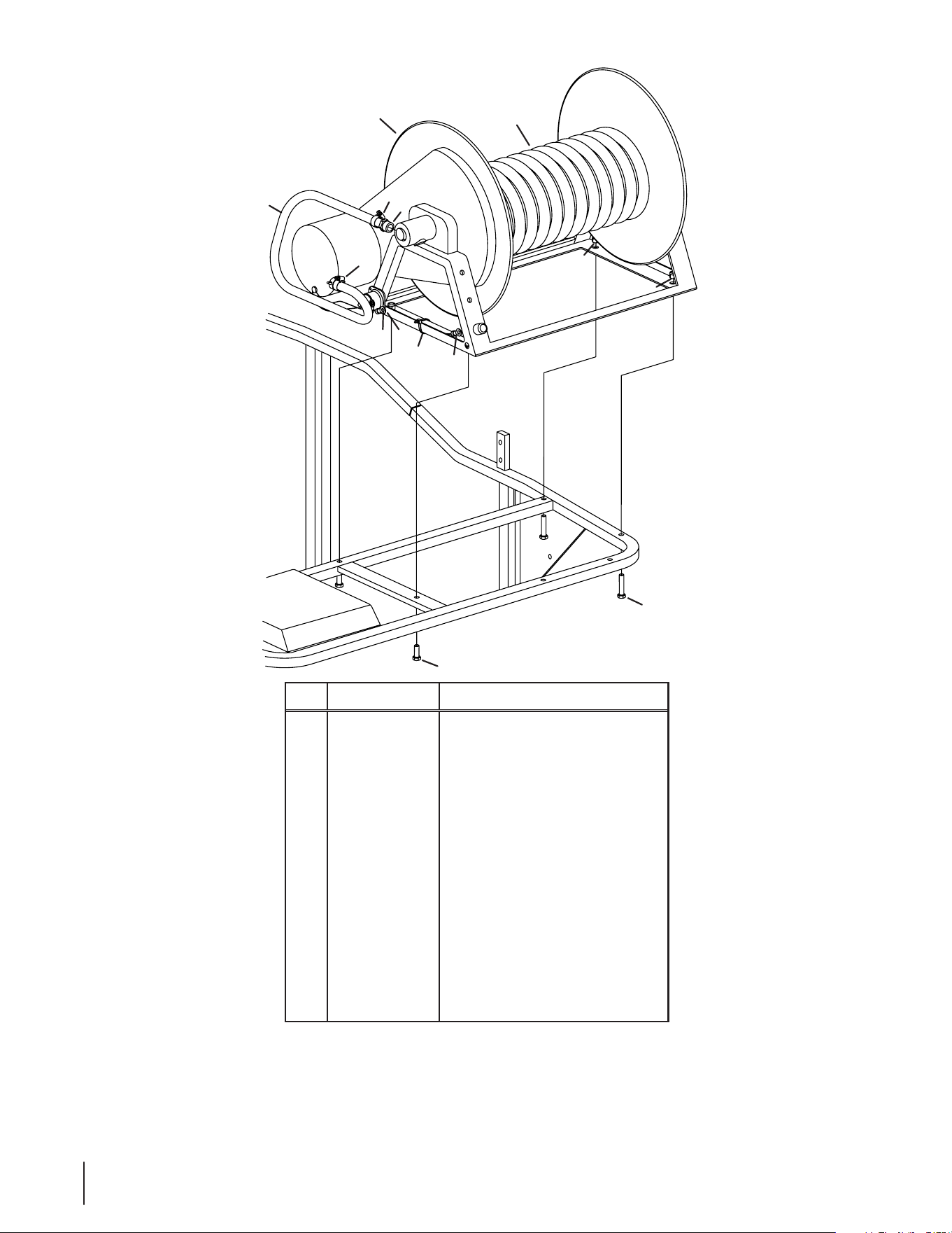
100/200/300 Gallon Hose Reel &
Mounting Assembly
Ref.
Part Number Description
1 00006417 Hose Barb, 1⁄2 x 1⁄2
2 00008295 Hose, 1⁄2
3 00010628 Ring Terminal, 3⁄8
4 00011459 Washer, .563 x 1.38 x .109
5 712- 04065 Lock Nut, 3⁄8-16
6 725-0157 Cable Tie
7 00020199 Hose Assembly, 1⁄2 x 300
8 01000216 Hose Clamp
9 750-3065 Spacer, .635 x .875 x .860
10 01002287 Reel Mounting
Ref.
Part Number Description
11 01003202 Reel Crossmember
12 01003359P Reel
13 680-00172 RH Hose Reel Weldment
14 680 -00173 RH Hose Reel Weldment
15 710-0489 Hex Screw, 1⁄2-13 x 2.00
16 710-0514 Hex Screw, 3⁄8-16 x 1.00
17 710-3181 Hex Screw, 1⁄2-13 x 1.50
18 712-3083 Hex Lock Nut, 1⁄2-13
NS 00010863 Wiring Kit
NS 01002319 Wiring Harness
30 se c t i O n 10 — il l u s t r a t e d pa r t s li s t
6
4
8
1
10
3
9
5
8
2
7
4
11
12
200 Gallon Compact Hose Reel &
Mounting Assembly
Ref.
Part Number Description
1 00006417 Hose Barb, 1⁄2 x 1⁄2
2 00008295 Hose, 1⁄2
3 00010628 Ring Terminal, 3⁄8
4 712- 04065 Lock Nut, 3⁄8-16
5 725-0157 Cable Tie
6 00020199 Hose Assembly, 1⁄2 x 300
7 00060033 Flat Washer, 1⁄4
8 01000216 Hose Clamp
9 01002319 Wiring Harness
10 01003359P Electric Hose Reel
11 710-0347 Hex Screw, 3⁄8-16 x 1.75
12 710-0514 Hex Screw, 38-16 x 1.00
NS 00010863 Wiring Kit

Notes
11
31

CUB CADET LLC
MANUFACTURER’S LIMITED WARRANTY
FOR COMMERCIAL LAWN APPLICATION EQUIPMENT
Cub Cadet LLC, P.O. BOX 361131 CLEVELAND, OHIO 44136-0019, Phone: 1-877-282-8684
MTD Products Limited, Kitchener, ON N2G 4J1, Phone: 1-800-668-1238
GDOC-100208 REV. A
IMPORTANT: To obtain warranty coverage owner must present an
original proof of purchase and applicable maintenance records to the
servicing dealer. Please see the operator’s manual for information on
required maintenance and service intervals.
The limited warranty set forth below is given by Cub Cadet LLC with
respect to new merchandise purchased or leased and used in the
United States and/or its territories and possessions, and by MTD
Products Limited with respect to new merchandise purchased or
leased and used in Canada and/or its territories and possessions
(either entity respectively, “Cub Cadet”).
Cub Cadet warrants this product (excluding its Normal Wear Parts,
Batteries and Attachments as described below) against defects in
material and workmanship for a period of one (1) year commencing
on the date of original retail purchase or lease and will, at its option,
repair or replace, free of charge, any part found to be defective in
materials or workmanship.
Normal Wear Parts are warranted to be free from defects in material
and workmanship for a period of thirty (30) days or one hundred
(100) operation hours, whichever comes first, commencing on the
date of original retail purchase or lease. Normal wear parts include,
but are not limited to items such as: belts, blades, blade adapters,
grass bags, rider deck wheels, seats, and tires.
Batteries have a one-year prorated limited warranty against defects
in material and workmanship, with 100% replacement during the
first three months. After three months, the battery replacement
credit is based on the months remaining in the twelve (12) month
period dating back to the original date of original sale or lease. Any
replacement battery will be warranted only for the remainder of the
original warranty period.
Attachments — Cub Cadet warrants attachments for this product
against defects in material and workmanship for a period of one (1)
year, commencing on the date of the attachment’s original purchase
or lease. Attachments include, but are not limited to items such as:
grass collectors and mulch kits.
This limited warranty shall only apply if this product has been
operated and maintained in accordance with the Operator’s Manual
furnished with the product, and has not been subject to misuse,
abuse, neglect, accident, improper maintenance, alteration,
vandalism, theft, fire, water, or damage because of other peril or
natural disaster. Damage resulting from the installation or use of any
part, accessory or attachment not approved by Cub Cadet for use
with the product(s) covered by this manual will void your warranty as
to any resulting damage. In addition, Cub Cadet may deny warranty
coverage if the hour meter, or any part thereof, is altered, modified,
disconnected or otherwise tampered with.
HOW TO OBTAIN SERVICE: Warranty service is available, WITH
PROOF OF PURCHASE AND APPLICABLE MAINTENANCE RECORDS,
through your local authorized service dealer. To locate the dealer in
your area:
In the U.S.A.:
Check your Yellow Pages, or contact Cub Cadet LLC at P.O. Box
361131, Cleveland, Ohio 44136-0019, call 1-877-282- 8684
or log on to our website at www.cubcadet.com.
In Canada:
Contact MTD Products Limited, Kitchener, ON N2G 4J1, call 1-800-
668-1238 or log on to our website at www.mtdcanada.com.
Without limiting the foregoing, this limited warranty does not provide
coverage in the following cases:
a. Routine maintenance items such as lubricants, filters, blade
sharpening, tune-ups, brake adjustments, clutch adjustments,
deck adjustments, and normal deterioration of the exterior finish
due to use or exposure.
b. Service completed by someone other than an authorized service
dealer.
c. Cub Cadet does not extend any warranty for products sold or
exported outside of the United States and/or Canada, and their
respective possessions and territories, except those sold through
Cub Cadet’s authorized channels of export distribution.
d. Replacement parts and\or accessories that are not genuine Cub
Cadet parts.
e. Transportation charges and service calls.
There are no implied warranties, including without limitation any
implied warranty of merchantability or fitness for a particular
purpose. No warranties shall apply after the applicable period
of express written warranty above. No other express warranties
beyond those mentioned above, given by any person or entity,
including a dealer or retailer, with respect to any product, shall
bind Cub Cadet. The exclusive remedy is repair or replacement of
the product as set forth above. The terms of this warranty provide
the sole and exclusive remedy arising from the sale and/or lease
of the products covered hereby. Cub Cadet shall not be liable for
any incidental or consequential loss or damage including, without
limitation, expenses incurred for substitute or replacement lawn
care services or for rental expenses to temporarily replace a
warranted product.
Some jurisdictions do not allow the exclusion or limitation of
incidental or consequential damages, or limitations on how long an
implied warranty lasts, so the above exclusions or limitations may not
apply to you.
In no event shall recovery of any kind be greater than the amount of
the purchase price of the product sold. Alteration of safety features of
the product shall void this warranty. You assume the risk and liability
for loss, damage, or injury to you and your property and/or to others
and their property arising out of the misuse or inability to use the
product.
This limited warranty shall not extend to anyone other than the
original purchaser or to the person for whom it was purchased as a
gift.
HOW LOCAL LAWS RELATE TO THIS WARRANTY: This limited
warranty gives you specific legal rights, and you may also have other
rights that vary in different jurisdictions.

