Commercial Tank Ride-On
Sprayer-Spreader
Professional Turf Equipment
OPERATOR’S MANUAL
40 Gallon Tank
125 lb Hopper

2
TABLE OF CONTENTS
Foreword. . . . . . . . . . . . . . . . . . . . . . . . . . . . . . . . . . . . . . . . . . . . . . . . . . . . . . . . . . . . . . . 3
General Safety Operations . . . . . . . . . . . . . . . . . . . . . . . . . . . . . . . . . . . . . . . . . . . . . . . . . 4
A.Danger . . . . . . . . . . . . . . . . . . . . . . . . . . . . . . . . . . . . . . . . . . . . . . . . . . . . . . . . . . 4
B. Warning . . . . . . . . . . . . . . . . . . . . . . . . . . . . . . . . . . . . . . . . . . . . . . . . . . . . . . . . . 4
C.Caution . . . . . . . . . . . . . . . . . . . . . . . . . . . . . . . . . . . . . . . . . . . . . . . . . . . . . . . . . . 4
Safety Precautions . . . . . . . . . . . . . . . . . . . . . . . . . . . . . . . . . . . . . . . . . . . . . . . . . . . . . . .4
A. General. . . . . . . . . . . . . . . . . . . . . . . . . . . . . . . . . . . . . . . . . . . . . . . . . . . . . . . . . . 4
B. Related to Fuel . . . . . . . . . . . . . . . . . . . . . . . . . . . . . . . . . . . . . . . . . . . . . . . . . . . . 5
C.Related to Batteries . . . . . . . . . . . . . . . . . . . . . . . . . . . . . . . . . . . . . . . . . . . . . . . . 5
D. When Applying Materials . . . . . . . . . . . . . . . . . . . . . . . . . . . . . . . . . . . . . . . . . . . . 5
E.General Requirements-Personal Protective Equipment . . . . . . . . . . . . . . . . . . . . . 6
F.Operator Protection System. . . . . . . . . . . . . . . . . . . . . . . . . . . . . . . . . . . . . . . . . . . 7
G.Hydraulic Devices and Systems . . . . . . . . . . . . . . . . . . . . . . . . . . . . . . . . . . . . . . . 7
Safety Decals . . . . . . . . . . . . . . . . . . . . . . . . . . . . . . . . . . . . . . . . . . . . . . . . . . . . . . . . . . . 9
Specifications . . . . . . . . . . . . . . . . . . . . . . . . . . . . . . . . . . . . . . . . . . . . . . . . . . . . . . . . . .10
Operating Instructions . . . . . . . . . . . . . . . . . . . . . . . . . . . . . . . . . . . . . . . . . . . . . . . . . . . 11
A. General. . . . . . . . . . . . . . . . . . . . . . . . . . . . . . . . . . . . . . . . . . . . . . . . . . . . . . . . . 11
B. Controls . . . . . . . . . . . . . . . . . . . . . . . . . . . . . . . . . . . . . . . . . . . . . . . . . . . . . . . . 12
C.Initial Adjustments . . . . . . . . . . . . . . . . . . . . . . . . . . . . . . . . . . . . . . . . . . . . . . . . 13
D. Zero Turn Break-In and Operating Procedures . . . . . . . . . . . . . . . . . . . . . . . . . . 13
E. Controls for Sprayer . . . . . . . . . . . . . . . . . . . . . . . . . . . . . . . . . . . . . . . . . . . . . . . 15
F. Set-Up for Sprayer . . . . . . . . . . . . . . . . . . . . . . . . . . . . . . . . . . . . . . . . . . . . . . . . 16
Maintenance and Service . . . . . . . . . . . . . . . . . . . . . . . . . . . . . . . . . . . . . . . . . . . . . . . . . 21
A. Hydraulic Oil . . . . . . . . . . . . . . . . . . . . . . . . . . . . . . . . . . . . . . . . . . . . . . . . . . . . . 21
B. Electrical System . . . . . . . . . . . . . . . . . . . . . . . . . . . . . . . . . . . . . . . . . . . . . . . . . 21
C. Tires . . . . . . . . . . . . . . . . . . . . . . . . . . . . . . . . . . . . . . . . . . . . . . . . . . . . . . . . . . . 23
D. Brakes . . . . . . . . . . . . . . . . . . . . . . . . . . . . . . . . . . . . . . . . . . . . . . . . . . . . . . . . . 24
E.
Hydraulic System . . . . . . . . . . . . . . . . . . . . . . . . . . . . . . . . . . . . . . . . . . . . . . . . . 24
F. Storage . . . . . . . . . . . . . . . . . . . . . . . . . . . . . . . . . . . . . . . . . . . . . . . . . . . . . . . . . 25
G.Pump . . . . . . . . . . . . . . . . . . . . . . . . . . . . . . . . . . . . . . . . . . . . . . . . . . . . . . . . . . 26
H.Tank . . . . . . . . . . . . . . . . . . . . . . . . . . . . . . . . . . . . . . . . . . . . . . . . . . . . . . . . . . . 26
I.In-Line Strainer . . . . . . . . . . . . . . . . . . . . . . . . . . . . . . . . . . . . . . . . . . . . . . . . . . . . 26
J.Hose. . . . . . . . . . . . . . . . . . . . . . . . . . . . . . . . . . . . . . . . . . . . . . . . . . . . . . . . . . . . 26
K.Storage and Winterizing . . . . . . . . . . . . . . . . . . . . . . . . . . . . . . . . . . . . . . . . . . . . 26
L.Cleaning the Spreader. . . . . . . . . . . . . . . . . . . . . . . . . . . . . . . . . . . . . . . . . . . . . . 26
Maintenance Schedule . . . . . . . . . . . . . . . . . . . . . . . . . . . . . . . . . . . . . . . . . . . . . . . . . . . 27
Performance Adjustments . . . . . . . . . . . . . . . . . . . . . . . . . . . . . . . . . . . . . . . . . . . . . . . . 29
A. High Speed Tracking Adjustment . . . . . . . . . . . . . . . . . . . . . . . . . . . . . . . . . . . . . 29
B. Engine RPM Check and Adjustment . . . . . . . . . . . . . . . . . . . . . . . . . . . . . . . . . . 29
C. Lap Bar Adjustment . . . . . . . . . . . . . . . . . . . . . . . . . . . . . . . . . . . . . . . . . . . . . . . 30
Troubleshooting Guide . . . . . . . . . . . . . . . . . . . . . . . . . . . . . . . . . . . . . . . . . . . . . . . . . . . 31
Wiring Diagram. . . . . . . . . . . . . . . . . . . . . . . . . . . . . . . . . . . . . . . . . . . . . . . . . . . . . . . . . 32
Warranty
This product may be covered by one or more of the following patents:
D409,208; 5,946,894; 6,070,690; Pending

3
FOREWORD
The Hydrostatic drive Zero-Turn Commercial Riding Sprayer-Spreader provides superb
maneuverability, for professional landscapers, commercial lawn service companies, profes
-
sional turf managers and golf course superintendents. The machine incorporates many safety
features that should be studied by all operators and maintenance personnel before use. The
list of safety precautions should receive particular attention.
The sprayer is designed to provide professional turfgrass managers with reliable spray
equipment. The sprayer includes 40 gallon polyethylene tank, 12 VDC electric powered
pump will maximum output of 4.8 GPM. This manual presents the operating and mainte
-
nance instructions necessary to keep your Cub Cadet Commercial Sprayer at peak effi-
ciency. If properly operated and maintained, your Cub Cadet Commercial Sprayer will
provide dependable service.
This manual presents all of the operating and maintenance instructions necessary to keep
your machine at peak efficiency. If operated and maintained properly, your machine will give
dependable service.
CAUTION:
Only thoroughly trained persons should operate and maintain this
machine. This machine can cause serious injury to anyone who
misuses it and does not understand its operation. For their personal
safety, all operators and maintenance personnel are required to
read this entire manual before operating the machine.
Hazard control and accident prevention are partially dependent
upon the design and configuration of the equipment. Notwithstand
-
ing, these factors are also dependent upon the awareness, concern,
prudence and proper training of the personnel involved in the oper-
ation, transport, maintenance and storage of the equipment.

4
GENERAL SAFETY
OPERATIONS
A. DANGER
1. Do not operate machine in confined areas where
exhaust gases can accumulate.
2. Do not operate machine without mower chute
deflector in place and operational.
3. Do not carry passengers.
B. WARNING
1. Do not operate machines under the influence of
alcohol or drugs.
2. Do not operate machines without all guards and
safety devices in place and functional.
3. Do not start machines if there are fuel or oil leaks
or spillage — clean it up.
4. Do not operate machines near spilled or leaking
fuels.
5. Do not stop or park machine over dry leaves,
grass, debris, etc. that could be combustible.
6. Use extreme care when backing up.
7. Do not operate machine on slopes greater than
15 degrees (27%).
8. Do not operate machines on slopes when trac-
tion is reduced (wet grass, ice, soft ground, loose
ground, leaves, pine needles, debris, etc.).
9. Avoid turning downhill if possible, go slowly and
use extra care when turning downhill.
10. Do not operate machines during reduce visibility
(low light, fog, rain, etc.).
11. Do not operate machines with non-approved
attachments.
12. Do not operate machines that are dam-
aged.....have machine repaired.
13. Do not operate machines that have not been
properly maintained.
14. Use only replacement parts that are the same or
equivalent to the original equipment.
15. Do not modify machines or any of their compo-
nents, especially the engine governor!
16. Do not operate machine for more than 2 hours
without hearing protection.
C. CAUTION
1. Use proper protective equipment when operating
machine (gloves, boots, and hearing protection
are recommended).
2. Read entire machine Operator’s Manual.
3. Make sure operators are fully trained in the safe
use of the machine.
4. Follow all safety instructions when using the
machine.
5. Keep all safety signs legible and properly
installed.
6. Do not check for hydraulic leaks with any part of
the body.
7. Do not add fuel to a machine when the engine is
running and/or the exhaust system is hot.
8. Keep machine clean and free of debris, grass,
leaves, oil, grease, etc.
9. Place lap bars in neutral/start position, set park
brake, disengage P.T.O., turn engine off, and
remove ignition key before you dismount from
machine.
10. Use machines laterally or diagonally across
slopes, avoid going downhill when possible.
11. Go slowly and use extra care when descending
slopes.
12. Use extra care when loading and unloading
machines from trucks or trailers.
SAFETY PRECAUTIONS
A. General
1. Read this Operator’s Manual before starting the
machine. Study the controls and learn the proper
sequence of operation.
2. Do not allow anyone to operate or maintain this
machine who has not read this manual. Never
permit children to operate this machine.
3. Never carry passengers.
4. Do not remove any shields, guards or safety
devices. If a shield, guard or safety device is
damaged or does not function, repair or replace
it before operating the machine.
5. Always wear safety glasses and safety shoes
when operating or maintaining this machine. Do
not wear loose-fitting clothing.
6. Disconnect the spark plug wires and remove the
key from the ignition to prevent the engine from
accidentally starting before performing any main
-
tenance on this machine.
7. Never run the engine indoors without adequate
ventilation. Exhaust fumes are deadly.
8. To avoid serious burns, do not touch the engine,
exhaust pipe or muffler while the engine is run
-
ning or until it has cooled after it has been shut
off.
9. The liquid in the battery is dilute sulfuric acid.
Always wear safety glasses and rubber gloves
when working on the battery. Do not overfill the
battery.
10. Lead-acid batteries generate hydrogen and oxy-
gen gases which form an explosive mixture.
Keep sparks and flames away at all times.
11. When looking for oil leaks, never run your hand
over hydraulic hoses, lines or fittings. Never
tighten or adjust hydraulic hoses, lines or fittings
while the system is under pressure. If high-pres
-
sure oil penetrates the skin, the oil must be
removed within a few hours by a doctor familiar
with this form of injury or serious complications
may result.

5
12. Keep adults, children and pets away from the
sprayer and the area to be sprayed.
13.
Do not operate or store the machine or fuel con-
tainer inside where there is an open flame,
spark or pilot light such as a water heater, fur
-
nace, clothes dryer, etc.
B. Related to Fuel
1. Fuel is highly flammable and its vapors can
explode if ignited. Please respect it.
2. Do not smoke or permit others to smoke while
handling fuel.
3. Always use approved containers for fuel and fill
slowly to decrease the chance of static electricity
buildup and spillage.
4. Store fuel in well ventilated and unoccupied
buildings away from sparks and flames.
5. When dispensing gasoline into approved con-
tainers, place the container on the ground when
refueling to avoid a possible static electricity igni
-
tion of fuel vapors.
6. Do not fill containers while it is inside a vehicle,
trunk, the bed of a pickup or floor of a trailer.
7. Always shut off the engine and permit it to cool
before removing the fuel tank cap.
8. Always fill the fuel tank outdoors.
9. If the fuel container spout will not fit inside the
fuel tank opening, use a funnel.
10. When filling the fuel tank, stop when the fuel
reaches one inch from the top. This space is neces
-
sary for tank expansion.
Do not overfill
.
11. Wipe up any spilled fuel.
C. Related to Batteries
1. The electrolyte in a lead-acid battery is dilute
sulfuric acid which is a very dangerous and
corrosive liquid. Always wear safety glasses
or goggles and rubber gloves when working
on a lead-acid battery.
2. Do not overfill a lead-acid battery when filling the
cells with distilled water.
3. Lead-acid batteries generate hydrogen and
oxygen gases which form an explosive mixture.
Keep sparks and flames away at all times.
D. When Applying Materials
1. Keep adults, children and pets away from the
area where materials will be applied.
2. When operating this machine in the forward
direction, DO NOT allow the steering levers to
return to the neutral position on their own.
Always maintain a firm grip on the levers, operate
them smoothly and avoid any sudden move
-
ments of the levers when starting or stopping.
3. Always remove debris and other objects from the
area where materials will be applied.(
Note
:
debris and loose grass will reduce traction.)
4. Use the machine only in daylight.
5. Watch for holes, sprinkler heads and other hid-
den hazards.
6. Avoid driving too close to trees, creeks, ditches,
sand traps and other obstacles.
7. Before backing up, check behind you and watch
where you’re going.
8. Always reduce speed when making a turn, and
when grass is wet.
9. Always travel across slopes, never up and down
the slope. Do not operate on steep slopes, and
slow down before turning.
10. Be careful when crossing gravel paths or road-
ways. Always allow other vehicles to have the
right-of-way.
11. If you hit a solid object while traveling, turn off the
main switch, place the left and right steering
levers in the neutral, opened-out position, move
the throttle to slow, set the parking brake, shut off
the engine and take the key from the ignition
switch. Inspect for damage. Repair any damage.
12. Never leave the machine unattended without:
placing the left and right steering levers in the
neutral opened-out position; moving the throttle
to slow; setting the parking brake; shutting off the
engine and taking the key from the ignition
switch.
13. Keep the machine and especially the engine and
hydraulic components clean and free of grease,
grass, leaves and materials to reduce the poten
-
tial for over-heating ad fire.
14. When spraying pesticides:
a.ALWAYS FOLLOW THE DIRECTIONS ON
THE LABEL
b.Avoid breathing vapors.
c.Avoid contact with skin, eyes or clothing.
d.Wear rubber boots or rubberized shoes.
e.Wear work clothes with long-sleeved shirts
and long-legged pants.
f.Change to clean clothing daily.
g.Wash hands and face before eating or smok-
ing.
h.Bathe thoroughly as soon after spraying as
possible.
15. Wear a face shield and rubber gloves when han-
dling concentrates.
16. Do not remove any shields, guards or safety
devices from the sprayer. If a shield, guard or
safety device is damaged or does not function,
repair or replace it before operating the sprayer.

6
E. General Requirements - Personal Pro-
tective Equipment
OSHA Standard 1910.132 through 1910.139
OSHA standard 1910.132 states in relevant part:
a. Protective equipment, including personal
protective equipment (PPE) for eyes, face,
head, and extremities, protective clothing,
respiratory devices, and protective shields and
barriers, shall be provided, used, and
maintained in a sanitary and reliable condition
whereever it is necessary by reason of
hazards of processes or environment,
chemical hazards, radiological hazards, or
mechanical irritants encountered in a manner
capable of causing injury or impairment in the
function of any part of the body through
absortion, inhalation or physical contact.
This standard is subject to change. Please check
www.osha.gov for the latest regulatory updates
General
Sometimes, it is not possible to reduce a hazard by eliminat-
ing it, substituting a less hazardous process or product,
making changes to equipment, or even by changing how
you do the job. That’s when you need personal protection.
PPE includes items like gloves, goggles, boots, hearing pro-
tection and respirators. Respirators filter out particles or
block gases and vapors that can harm the respiratory sys
-
tem. With a surface area well supplied with blood vessels
and equal in size to a tennis court, the lungs are the quickest
and most direct route for absorbing harmful substance into
your body.
Note:
PPE does not prevent accidents, but it does prevent
or reduce injury and even fatalities when used properly.
Equipment (PPE)
Protective equipment must be selected carefully. Always
test fit the protective equipment to be sure it fits properly and
comfortably. If it isn’t comfortable -- it won’t be worn; if it isn’t
worn -- it won’t protect. PPE includes:
• respirators
• chemical-resistant clothing
• hearing protectors
• gloves
• safety goggles and glasses
• hard hats
• sensors to detect hazardous substance
• communication devices used for safe
deployment of workers
Inhaling pesticide fumes and mists is a very common entry
route of pesticides into the body. Absortion through the
lungs is great and the sensitivity is high.
The National Institute for Occupational Safety and Health
(NIOSH), under authority of the Federal Mine Safety and
Health Act of 1977 and the Occupational Safety and Health
Act of 1970, tests, approves, and certifies respiratory equip
-
ment as being safe for its intended purpose.
Note:
Always be certain that the NIOSH compliance num-
ber is on the product before purchasing respiratory equip-
ment.
Two systems of respiratory protection are available, de-
pending on the type of respiratory risk involved: air-purifica-
tion (filtering) and air-supplying. For most pesticide work,
the air-purifying equipment is adequate and safe.
Protective equipment is usually required by the pesticide la-
bel in one form or another and is integral to safe pesticide
application. Chemical-protective clothing consists of multi
-
layered garments made out of various materials that pro-
tect against a variety of hazards. Because no single
material can protect against all chemicals, multiple layers
of various materials usually are used to increase the de
-
gree of protection. Protection is maximized by total encap-
sulation (completely covering the wearer). An assortment
of types of chemical-protective hats, hoods, gloves, and
boot covers are used with the garments.
There are many brands and models of protective equip-
ment available for use in pesticide application. Price is not
always an indicator of quality, so shop carefully.
Note:
Select equipment that is
NIOSH tested and ap-
proved.
Protective equipment, appropriate for the task and hazards
that an employee could be exposed, shall be provided by
the employer. Since comfort and proper fit must be consid
-
ered, the person who is going to use it must select the prop-
er size to ensure correct fit and function. Unused protective
equipment does not help anyone.
Note:
Many supply centers, hardware stores, chemical re-
tailers, and equipment/machinery dealers keep protective
equipment in stock.
Training
Written procedures shall be developed for PPE use. These
procedures shall include all information and guidance nec
-
essary for their proper selection, use and care. The employ-
er shall provide fitting instructions including demonstrations
and practice in how the PPE should be worn, It is essential
that both supervisors and workers be properly instructed in
PPE selection, use, and maintenance. Training shall pro
-
vide the workers an opportunity to handle PPE, and have it
fitted properly.
When to replace PPE
All PPE shall be inspected routinely before and after each
use. A program for maintenance and care of PPE shall be
initiated and be adjusted to the type of work place, working
conditions, and hazards. It shall include the following:
7
• inspection for defects and damage
• cleaning and disinfecting
• repair
•storage
Many factors influence how long PPE (especially respira-
tors) remains effective. As well as hours of use, an air-puri-
fying respirator’s service life is affected by the concentration
of dust and other contaminants in the enviroment; the user’s
body size; how strenuously the user works while the respi
-
rator is worn; and how the respirator is stored.
Note:
As a result, it’s not possible to specify a length of time
after which a respirator should be replaced.
In general, replace a mask or filter when it is visibly dirty or
damaged, or when you experience difficulty breathing
through it. Replace respirator cartridges when you can
smell or taste chemical while or after using the respirator, or
according to the manufacturer’s recommendations. Re
-
placement or repairs shall be done only by experienced per-
son with parts designed for the PPE. No attempts shall be
made to replace components or to make adjustments or re
-
pairs beyond the manufacturer’s recommendations.
F. Operator Protection System
1. This machine is equipped with an Operator
Protective System (OPS), which includes:
a. A Roll Over Protective Structure (ROPS) or
Operator Protective Device (OPD) of the
fixed configuration
b. Seat belt assembly with retractable function
2. ROPS and OPDs are structures designed to
provide a crush-resistant space for the opera
-
tor when properly seat-belted within the desig-
nated seating area of the machine in the event
of a machine tip-over or roll-over.
DANGER:
Damaged ROPS and OPDs must be replaced prior to
operator use!
3. Seat belts shall be used and shall be properly
fastened about the operator’s waist at all times,
except when the ROPS or OPDs are:
a. not properly installed and/or not properly
secured onto the machine
b. damaged in such manner that their struc-
tural integrity has been compromised
4. Seat belts are attached to the movable portion
of the seat when suspension seats are utilized,
and therefore the seat-mounting base must be
secured to its pivot means and the pivot means
latched to the frame of the machine.
DANGER:
If ROPS and OPDs are missing, seat belts shall not
be fastened. Worn or damaged seat belt assemblies
must be replaced prior to operator use.
5. The ROPS and seat belt are integral parts of
this machine and should not be tampered with,
modified in any manner, or removed.
6. The ROPS extends behind the operator posi-
tion, and therefore the operator must be aware
of potential contact of the ROPS with items such
as trees, buildings, doorways, clothes lines, util
-
ity wires, etc., that could cause the machine to
upset or rollover....use caution in (or avoid)
areas where the ROPS could come in contact
with any structures, trees, etc.
7. The ROPS and seat belt add additional mass
that elevates the machine’s Center of Gravity
(C.G.) which negatively affects the machine’s
stability and traction....use extra caution when
operating on slopes.
8. Inspect the ROPS and seat belt assemblies on
a regular basis for damage and improper opera
-
tion....replace all components that are damaged
or are not functioning properly with authorized
replacement parts.
9. Failure to use the seatbelt properly could result
in serious injury or death if an accidental over
-
turn occurs. In order for the ROPS to be effec-
tive, the seat belt must be securely fastened
around the operator at all times when the opera
-
tor is on the machine. Contact with the ROPS
during an overturn could cause serious injury or
death.
10. The ROPS will not prevent the machine from
upsets or roll overs.
11. Only approved attachments should be used on
this machine.
G. Hydraulic Devices and Systems
Hydraulic fluid escaping under pressure may have suf-
ficient force to penetrate skin and to cause serious
imjury. If foreign fluid is injected into the skin, it mst be
surgically removed within a few hours by a doctor famil
-
iar with this form of injury, or gangrene may result.
Warning: Keep body and hands away from pin-
holes or nozzles that could eject hydraulic fluid
under high pressure. Use paper or cardboard, not
hands, to search for leaks!
Safely relieve all pressure in the system before
performing any work on the system, and make sure
that:
• the ignition switch is OFF
• the key is removed

8
• the engine sparkplug wire(s) removed
• all connections to the negative terminal of the
battery are removed
• the park brake is set
• all by-pass valves, if so equipped, are open
• hydraulic controls are actuated to release
pressure on pumps, cylinders, etc. If “float”
positions are available, they should be used.
After the above operations are completed, it should
be safe to begin disconnecting the lines or compo
-
nents. It is still a good idea to cover the connection
with a cloth shield and then gently loosen connec
-
tions.
Warning: Make sure all hydraulic fluid con-
nections are tight and all hydraulic hoses and
lines are in good condition before applying
pressure to the system.
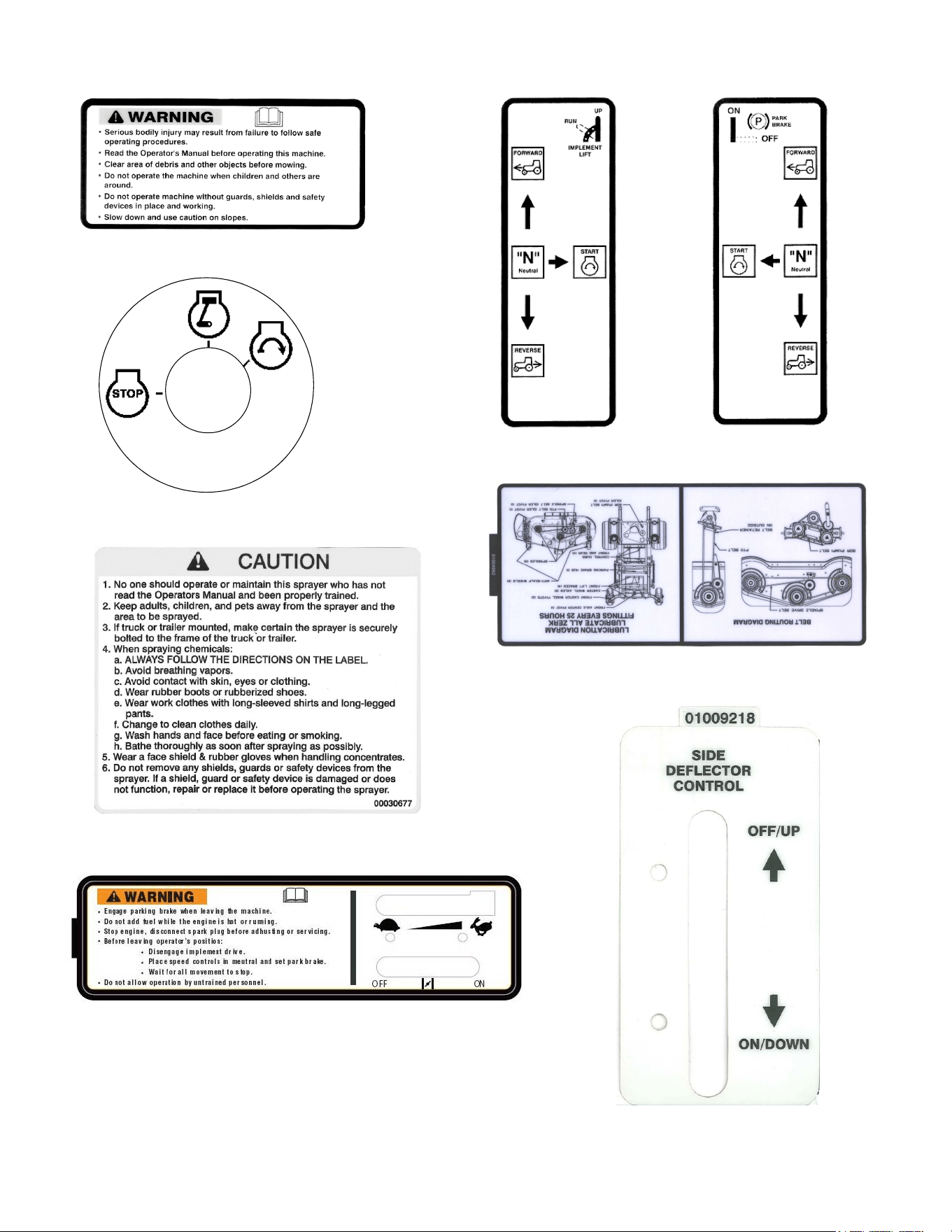
Part Number: 00030677
Part Number: 01003449
Part Number: 01004992
Part Number: 01003857
Part Number: 01003452Part Number: 01003451
Part Number: 02000162
Part Number: 01009218
9
SAFETY DECALS AND LABELS

10
SPECIFICATIONS
Engine: 17HP Kawasaki
Type: Vertical air cooled V-Twin
Air Cleaner: Paper Element with foam pre-cleaner
Lube System: Pressurized with oil filter
Starter: 12-volt electric
Traction Drive: Dual variable-speed hydraulic pump and wheel
Hydraulic Tank: 10 quart capacity, One quart filter
Controls: Engine ignition and start switch; throttle; choke; left and right
steering levers; electric power switch; parking brake; foot oper
-
ated spreader rate gate; side deflector; spreader power; sprayer
power
Parking Brake: Mechanical linkage attached to the brake handle, drum brakes
Front Caster Wheels: 13 x 6.50 x 6
Tire Pressure: 8-10 psi Rear, 20-25 psi front caster
Drive Wheels: 24x12 - 12
Frame: 2" Steel square tube and plate, all welded construction
Seat: Adjustable seat with armrests. 5" Adjustment
Fuel Tank: 6.5 gallon w/ shutoff valve
Ground Speed: 0-10 + MPH forward. 0-4 MPH reverse
Instrumentation: Hour meter, Tachometer, Maintenance-minder
Tank: 40 gallon polyethylene
Pump Motor: 12 VDC permanent magnet
Pump: 4.8 GPM @ 40 psi, diaphram-type
Strainer: In line 30 mesh, stainless steel
Agitation By-pass, triple-jet
Pressure Regulator: Adjustable valve with 60 psi glycerine-dampend gauge
Sprayer Boom: 10 foot, 3 section, 1: O.D. square tubular steel
Spray Nozzles Five FL8VD wide angle full cone tips, 20” centers
Spreader Hopper: 125 pound capacity
Net Weight: 950 lbs
11
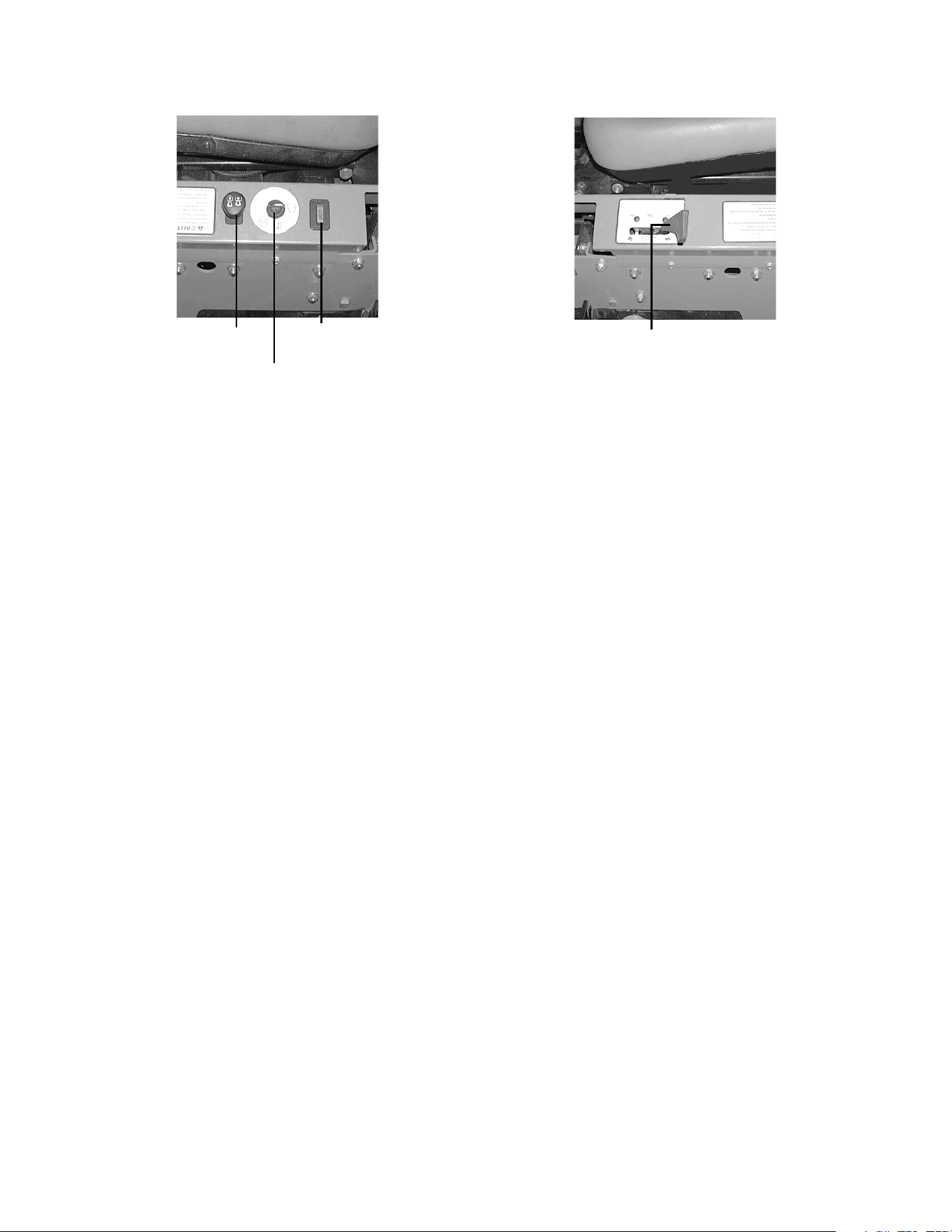
OPERATING INSTRUCTIONS
Figure. 1 Figure. 2
Ignition Switch
Main Power
Switch
Tach and
Hour Meter
Engine throttle/
Choke Lever
A.General
1. When Applying Materials:
a. Keep adults, children, and pets away from the
area where material will be applied.
b. When operating this machine, in the forward
direction, do not allow the steering levers to
return to Neutral on their own. Always main
-
tain a firm grip on the levers, operate them
smoothly and avoid any sudden movements
of the levers when starting and stopping.
c. Always remove debris and other objects from
the area where materials will be applied
(Note: debris and loose grass will reduce trac
-
tion).
d. operate machine only in daylight.
e. Watch for holes, sprinkler heads, and other
hidden hazards.
f. Avoid driving too close to trees, creeks,
ditches, sand traps, and other obstacles.
g. Before backing up, check behind and watch
where you are going.
h. Always reduce speed when making a turn,
and when grass is wet.
i. Always travel across slopes, never up and
down the slope. Do not operate on steep
slopes and slow down before turning. Avoid
turning downhill if possible, start at the bottom
and work up to the top. Use extra care and go
slowly when turning downhill.
j. If you hit a solid object while traveling, turn off
the main switch, place the steering levers in
the neutral, opened-out position, move the
throttle to slow, set the parking brake, shut off
the engine, and take the key from the ignition
switch. Inspect for damage. Repair the dam
-
age.
k. Never leave the machine unattended without
observing the following: placing the steering
levers in the neutral open-out position, mov
-
ing the throttle to slow, setting the parking
brake, shutting off the engine and taking the
key from the ignition switch.
l. Keep the machine and especially the engine
and hydraulic components clean and free of
grease, grass, leaves and materials to reduce
the poterntial for over-heating and fire.
2. Safety Awareness when Applying Materials
a. Do not operate on steep slopes, those above
15 degrees (27% slope).
b. Avoid turning downhill if possible, if not use
extra care and go slowly.
c. Avoid turning when going downhill, traction is
at a minimum going downhill.
d. Avoid operation or use extreme care if the
traction surface is wet, unstable, or slippery.
e. Use extra care when grass clippings, leaves,
pine needles, or debris are present as traction
can be reduced.
f. Slow-down before turning and come to a
complete stop before any zero turn maneuver.
g. Do not stop machine or park machine over
combustible materials such as dry grass,
leaves, debris, etc.
3. To Apply Product in a Pattern
a. Pick a point on the opposite side of the area
to be mowed (post, tree, shrub, etc.).
b. If on an hillside, start at the bottom so that the
turns are uphill rather than downhill.
c. Align the machine so as to head directly
toward the object on the far side.
d. Slowly increase the speed of the machine to
match conditions, terrain, and operator famil
-
iarity with the controls and keep the machine
headed directly toward the alignment object.
e. When approaching the other end of a strip,
slow down or stop before turning. A U-turn is
recommended unless a zero turn is required.
The speed of a U-turn that will allow for

12
machine controllability and minimal turf
defacement will be dependent on several fac
-
tors including: the speed of the turn, the
radius of the turn, the tire tread pattern, the
traction coefficient of the tire to the traction
surface, the slope of the traction surface.
f. Remember, a zero turn requires that the for-
ward or reverse travel of the machine be
stopped prior to the initiation of the turn or
severe turf defacement can occur.
g. To prevent rutting or grooving of the turf,
change the direction that the strips are trav
-
eled by approximately 45 degrees the next
and each subsequent time that materials are
applied to the area.
B.Controls
1.
Engine Ignition and Start Switch:
(See Figure
1.) Located on the instrument housing below the
right side of the operator’s seat. When the key is
inserted and turned clockwise, 45 degrees, the
ignition circuit is closed. Turning the switch fur
-
ther against spring pressure starts the engine.
The engine will only start if the main switch is in
the “off” position, the parking brake is engaged
and the left and right steering levers are in the
neutral, opened-out position. The key should
always be removed from the switch if the opera
-
tor leaves the machines seat.
2.
Engine Throttle Control:
(See Figure 2.)
Located on the left side of the machine next to
the operator’s seat. Moving the throttle control
from the rear to the front will increase the engine
speed from slow to fast.
3.
Left and Right Steering Levers:
(See Figure 3.)
These hinged levers open out to the side in the
neutral position to permit the operator to be
seated or to leave the machine’s seat. The oper
-
ator, when seated, can pull the levers up to the
operating position, a comfortable forearm’s
length away. These levers control all of the move
-
ments of the machine. Pushing both levers for-
ward causes the machine to move forward.
Pulling both levers back causes the mower to
machine backward. Pushing one lever ahead of
the other lever causes the traction wheel on the
side where the lever is ahead to rotate faster
than the other traction wheel, making the
machine turn toward the side where the lever is
behind. When one lever is pushed forward and
the other lever pulled back the same amount,
one traction wheel will turn in reverse and the
machine will turn within its own length.
In order to start the engine, both steering levers
must be opened out to the side in the neutral
position; the parking brake must be engaged;
and the main power clutch switch must be “off”.
However, once the engine starts, the parking
brake must be released before the operator
places the steering levers into the operating
position or the engine will automatically shut off.
Note: The Steering Levers will return toward neu-
tral when released, but they should be placed in neu-
tral by the driver. If the Drive Handles are not placed
in neutral, the machine could creep.
4. Main Power Switch:
(See Figure 1.) Located on
the right side of the mower beside the ignition
switch. This is an “on/off” push pull switch that
controls the main electric power which supplies
power to the spreader and the sprayer operating
switches in the lap bar handles. The switch must
be turned off to start the engine and should be
turned off for safety any time another person
approaches the machine. Power to the main
switch will also be cut off if the operator leaves
the operator’s seat.
5.
Parking Brake:
(See Figure 3.) Located on the
left side of the traction unit. The handle is an
overcenter lever which applies the drum-type
brake on each drive wheel when the handle is
pulled to the rear. The brake must be engaged in
order to start the engine.
Brake
Steering Levers
Figure. 3
6.
Fuel Shutoff Valve:
(See Figure 4.) Located on
top of the fuel tank. When turned in a clockwise
direction until it stops, it will shut off the flow of
fuel to the engine. When turned in a counter
-
clockwise direction it will open and allow fuel to
flow to the engine. Close this valve if you are not
going to run the machine for a period of 30 min
-
utes or more to prevent flooding the engine.
Fuel Shutoff Valve
Figure. 4
Note: The fuel tank
capacity is 6.5 gallons.
13
7.
Seat Adjustment Lever:
The Seat Adjustment
Lever is located beneath the seat. The Seat
Adjustment Lever is used to move the seat for
-
ward and backward. To place the seat in the
desired position pull the seat adjustment lever to
the left then push the seat forward or back to the
desired position. Release the lever so the seat
will lock in place.
8.
Digital Tachometer and Hour Meter:
(See Fig-
ure 1) Located on the right side of the machine in
front of the ignition switch. When the machine is
running the tachometer displays engine rpm.
When the machine is off the tachometer displays
running time.
9.
Choke Lever:
(See Figure 2) The Choke is part
of the throttle control on the left instrument panel
next to the seat. The Choke is operated manually
when the throttle is moved forward past the
detent. Having the Choke in the ON position
helps the engine to start during initial start-up.
During normal operation the Choke should be
OFF, move throttle aft to the detent location.
10. Speed Control Adjusters:
Flip-in, flip-out speed
limiters are provided for spray operations. They
limit the maximum forward speed to 4.5
+ 0.2
mph.
Note: There will be a flashing “LUBE” for each
recommended lubrication interval. There is a
flashing “OIL” at each recommended engine oil
and filter change.
C.Initial Adjustments
1. Check the fluid levels and tires:
Note: These checks should be made daily,
before starting the engine.
a. Fuel: Using a good grade of unleaded, regu-
lar gasoline (for a gasoline engine), fill the fuel
tank (beside the engine on the right side of
the machine). When the fuel reaches one inch
from the top of the tank, stop. DO NOT OVER
-
FILL. Space must be left for expansion.
b. Engine Oil: (Filled at the factory before ship-
ment.) Pull out the oil dipstick, wipe it off and
reinsert it. Pull it out again and read the oil
level. If it is below the operating range, add oil
through the fill tube using a funnel to bring it
up to the top of the operating range.
Note: Gasoline Engine: Use SAE 15W40
engine oil, rated for service SJ.
c. Hydraulic Oil: (Filled at the factory before
shipment.) The hydraulic oil tank is located
beneath the operator’s seat. Always wipe off
the area around the oil tank fill neck before
checking the oil level to prevent dirt from con
-
taminating the oil. Remove the cap and make
sure the oil level is up to the lowest hole on
the oil tank fill neck. The top hole is for vent
-
ing. If the oil level is low, fill with a good grade
of SAE15W-40 oil.
d. Tires: 8-10 psi Rear, 20-25 psi Front Caster
Tires
Note: New tires are overinflated in order to
properly seat the bead to the rim. The normal
working pressure for the traction tires is 8-10 psi.
The front caster wheels should be inflated to 20-
25 psi.
2. Check that all Nuts, Bolts and Screws are
Tight.
D. Zero Turn Break-In And Operating Pro-
cedures
The following procedures are suggested for operators
of ride-on machines which have zero turn capabilities.
1. Orientation:
a. Read the entire Operator’s Manual.
b. Sit on the machine, adjust the seat before-
and-after, then adjust the speed/directional
(lap bar) controls (they can be adjusted
before-and-after, as well as up-and-down —
9/16" wrench required).
c. Become familiar with all of the machine con-
trols, instrumentation, safety and instruction
signs, and safety devices.
d. Move (or have moved) the machine to a safe,
level area with no obstructions including
objects, pedestrians, and animals.
2. Initial Operation:
a. Use protective equipment for eyes, hands,
hearing, feet, legs, head and other areas of
the body if needed — safety eye glasses,
gloves, earplugs, boots, hats, etc.
WARNING:
Hearing Protection is required for all operator
exposure exceeding two (2) hours.
b. Ensure that the area is free of animals and
bystanders, especially children!
c. Survey the area where the equipment is to be
used to make sure it is free of debris, sticks,
stones, wires, bones, and other foreign
objects which could cause injury to bystand
-
ers, damage to the machine, or damage to
nearby facilities.
d. Inspect the machine to make sure:
1. All guards, shields are in their proper place,
are secure, and are functional.
2. That there are no spilled or leaking fuel or
oil sources, nor loose fuel or hydraulic tank
caps, hoses or fittings.
3. That there are no loose or missing hard-
ware nor any missing items.

14
4. That no non-approved devices are installed.
5. That all safety signs and decals are prop-
erly installed and legible.
e. This is a one person machine, operator only!
Riders are not permitted under any circum
-
stance!
f. To start the engine on the machine:
1. Make sure the park brake is set to the “ON”
position, both lap bars are in the neutral/
start (opened-out) position, and the main
power switch is in the “off” (down) position.
2. Move the throttle control forward to engage
the engine choke.
3. Insert the ignition key, turn the switch
toward the spring-loaded “Start” position,
maintain the Start position until the engine
begins to run, then release the switch (it will
return to the “Run” position).
4. Retard the throttle slowly by moving it rear-
ward to release the choke. If the engine is
“cold”, the choke may need to be partially
applied for a few minutes. Be sure to totally
retard the choke after the engine has
“warmed up”.
g. Check safety devices:
1. With the park brake engaged, move one of
the lap bars (speed/directional control) from
the neutral/start position to the neutral posi
-
tion (out of the slot, toward the center of the
machine) — the engine should stop run
-
ning. Move the lap bars back to the neutral/
start position and the engine should run.
2. Repeat this procedure with the opposite
side lap bars.
3. With the park brake engaged and the lap
bars in the neutral/start position, advance
the engine speed control completely for
-
ward (Hi-idle), engage the main power
switch (pull upward), then lift off the seat —
the engine should stop running. Sit down
and the engine should run. Turn off the
main power switch by pushing the control
switch down.
h. To drive in the FORWARD direction:
1. Set the engine speed to 2000 to 2500 rpm
(refer to tachometer on right control panel).
This must be increased to full speed (3525-
3675 rpm) after becoming familiar with the
machine.
2. Release the park brake.
3. Move both lap bars out of the neutral/start
position to the neutral position (toward cen
-
ter of machine). Slowly, move both lap bars
toward the front of the machine until the
machine begins to move forward — release
the lap bars and the machine should stop.
The more that the lap bars are moved
toward the front of the machine, the faster
the machine will move in the forward direc
-
tion. Release the lap bars and the machine
should stop traveling forward. (This is a
safety check, the normal procedure is for
the operator to slowly bring the lap bars to
the neutral position).
4. Do not advance the lap bars rapidly as this
could cause turf defacement, loss of trac
-
tion, and/or instability.
5. To turn, advance one lap bar ahead of the
other and the machine will turn toward the
opposite from the side that was advanced
— I.E. to turn clockwise (to the Right), move
the LEFT lap bar forward more than the
right side, and to turn counter-clockwise (to
the LEFT), move the RIGHT lap bar forward
more than the left side. NOTE: If one lap bar
is in the neutral position and the other is
advanced, the turn side tire will not rotate
and a “pivot turn” will be executed — turf
defacement could occur (if on grass) as well
as potential damages to the traction surface
and the tire. If the lap bar on the turn side is
not brought all the way to neutral, then the
turn side tire will continue to rotate and a
“U-turn” will be executed with a low potential
for turf defacement as well as traction sur
-
face and tire damage.
i. To drive in the REVERSE direction:
1. Make sure no bystanders, animals, or
objects are behind the machine. Look
behind the machine, and use extreme care.
2. Slowly, move both lap bars toward the rear
of the machine until the machine begins to
move rearward. Release the lap bars and
the machine should stop. The more the lap
bars are moved toward the rear of the
machine, the faster the machine will move
in the reverse direction. Release the lap
bars and the machine should stop traveling
in reverse (this is a safety check, the normal
procedure is for the operator to slowly bring
the lap bars to the neutral position).
3. Do not retard the lap bars rapidly as this
could cause turf defacement and/or loss of
traction.
4. To turn, retard one lap bar ahead of the
other and the machine will turn toward the
same side that was retarded — I.E., to turn
counter-clockwise (to the LEFT), move the
LEFT lap bar rearward more than the right
side, and to turn clockwise (to the RIGHT),
move the RIGHT lap bar rearward more
than the left side. NOTE: If one lap bar is in
the neutral position and the other is
retarded, the turn side tire will not rotate
and a “pivot turn” will be executed. Turf
defacement could occur (if on grass) as well

15
as potential damages to the traction surface
and the tire. If the lap bar on the turn side is
not brought all the way to neutral, then the
turn side tire will continue to rotate and a “U-
turn” will be executed with a low potential for
turf defacement as well as traction surface
and tire damage.
j. To perform a “zero turn”:
1. Please note, a zero turn maneuver can not
be executed while the machine is moving in
the Forward or, Reverse directions, the
machine must come to a stop first.
2. To turn clockwise, slowly move the LEFT lap
bar forward while simultaneously moving
the RIGHT lap bar rearward. Release both
lap bars and the machine should stop turn
-
ing.
3. To turn counter-clockwise, slowly move the
RIGHT lap bar forward while simultaneously
moving the LEFT lap bar rearward. Release
both lap bars and the machine should stop
turning (this is a safety check, the normal
procedure is for the operator to slowly bring
the lap bars to the neutral position).
3. Start the Engine:
a. Open the fuel shutoff valve.
b. Sit on the Seat. Set the parking brake “On”.
c. Move the left and right steering levers to the
neutral, opened-out position.
d. Turn the main power switch “Off”.
e. Push the throttle control to a position a third of
the way between slow and fast.
f. Insert the key in the ignition and start switch
and turn the switch to “On”.
g. Gasoline Engine: If the engine is cold, push
the choke to the on position.
h. Turn the ignition key in a clockwise direction to
the “Start” position until the engine starts.
Note: Do not hold the key in the “Start” posi-
tion for more than 10 seconds or you may dam-
age the starter. If the engine does not start in this
time, wait about 30 seconds and try again.
i. Gasoline Engine: Once the engine starts,
push the choke on halfway and as the engine
warms, push the choke off all the way.
4.
Operating the Machine:
Operating a zero-turn-
ing-radius machine is not like operating a tractor-
type riding machine. The zero-turning-radius
machine is much more maneuverable and much
less fatiguing to operate. However, getting used
to the fingertip control of the zero-turning-radius
machine takes some practice. We strongly rec
-
ommend that you locate a “test area” where you
can operate the machine for about 30 minutes
without being disturbed.
a. Get into the operator’s seat.
b. Start the engine.
c. After the engine has warmed, adjust the throt-
tle to the fast position.
d. Release the parking brake.
e. Fold in the steering levers to the operating
position.
WARNING:
When operating this machine forward, do not
allow the steering levers to return to the neutral
position on their own. Always maintain a firm grip
on the steering levers, operate them smoothly
and avoid any sudden movements of the levers
when starting or stopping.
f. To go forward, move both steering levers
slightly forward and the machine will slowly
move forward. The farther you move the
levers forward the faster the machine will go
forward.
g. To back up, move both steering levers slightly
backward and the machine will slowly move
backward. The farther you move the levers
backward the faster the machine will go back
-
ward.
h. To turn, pull the lever back on the side to
which you want to turn. The farther back you
pull the lever, the faster and more sharply you
will turn. Initially, you will have to be careful to
avoid turning to fast and too far.
5. Parking the Machine:
a. Push off the main power switch.
b. Drive the machine to the cleanup or storage
area.
c. Move the throttle to slow.
d. Place the steering levers in the neutral posi-
tion.
e. Set the parking brake.
f. Turn off the ignition switch and take the key
from the switch.
g. Close the fuel shutoff valve.
E.Controls for Sprayer
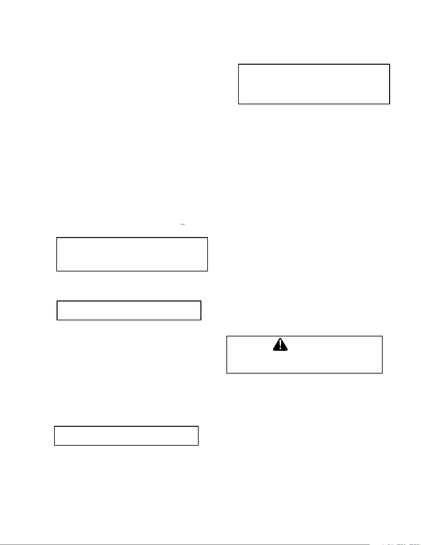
1. Valves
There are several ball valves used on the spray-
ers. They serve as pump outlets and are
mounted under the pressure regulator. Ball
valves operate with a quarter turn movement of
the handle. When the handle lines up with the
direction of flow, the valve is open. When the
handle is at a 90° angle to the direction of flow,
the valve is closed. There is a gate valve in the
suction line at the front of the engine plate near
the drain fitting. The handle should be turned all
the way counterclockwise to open the valve and
all the way clockwise to close the valve. To
drain the tank, the cap must be removed from

16
the drain fitting and the gate valve must be
opened.
2. Pressure Gauge
Mounted in the pressure regulator housing, the
pressure gauge indicates the pressure in the
output line to the spray gun, wand or boom and
the line to the hydraulic agitator, if used. The
gauge is graduated in pounds per square inch
(psi) and kilopascals (kPa).
3. Pressure Regulator
Located on the side of the pump opposite the
drive shaft. There are different styles of
regulators, but they all function in the same way.
A spring-loaded plunger rests against a valve
seat which forces the pump flow to the outlets.
The springs are opposed by the hydraulic
pressure generated by the pump. If this pressure
exceeds the spring pressure, the plunger is lifted
off of its seat and part or all of the flow goes to
bypass. All of the pressure regulators have
operating levers which in one position, remove
the spring pressure from the plunger and permit
the pump's flow to dump to bypass and in the
other position, apply the spring pressure to the
plunger and force the pump's flow to the outlets.
One valve has a toggle-type operating lever with
a ball which can be hooked in different notches
for adjustment. Another regulator has a knob that
turns about 90° from "OFF" to "ON". Still another
has a hinged part of the plunger shaft work as the
operating lever. All of the regulators also have a
means for adjusting the operating pressure. This
is a threaded knob, a ring or a brass adjustment
nut which when threaded down toward the base
of the pressure regulator, increases the spring
pressure.Normally, the regulator should be set to
provide about 100 psi with both output ball valves
closed. Then the output ball valve to the
application device is opened completely and with
bypass or pressurized jet agitation, the output ball
valve to the agitator line is adjusted to provide the
desired flow rate and with the mechanical
agitation, the pressure regulator is adjusted to
provide the desired flow rate.
Pressure to
Left side Boom
Pressure to
Center Boom
Pressure to
Right side Boom
Pressure from Pump
Return to Agitator
F.Set-Up for Sprayer
1. General
Check all bolts on the sprayer for tightness. Make
certain all hose clamps are tight. Check that bolts
on the tank support are tight on poly-tank. Check
that electrical connections are sound on electric
sprayers.
2. Starting the Sprayer (Electric-Powered)
a. Check the battery connections.
b. Clean the in-line strainer if it is dirty.
c. Fill the tank one third full with clean water.
Make certain the gate valve in the suction line
is open.
Cub Cadet Commercial Electric Sprayers are designed
to run in demand operation or constant operation.
Demand Operation
Close the ball valve (No. 1 in the the drawing on page
17) which stops all flow to the agitator, push the handle
on the directo valve (No. 2) down which permits flow to
the spray wand and turn on the pump switch. This will
force all of the flow from the pump to go to the spray
wand. The pump will operate for a short period to fill the
hose to the spray wand and then will shut off. With the
valves in this position, the pump will turn on when the
spray wand is turned on and will shut off when the spray
wand is turned off.
Note: If you are using a 1.5 GPM spray tip, the pump
will turn on and off as you spray because the pump can
output 4.8 GPM.
Note: The pressure gauge should show no more than
45 psi when the spray wand is off. This is controlled by
the pressure switch (No. 3) which is preset at the fac
-
tory. Pressure greater than 45 psi will activate an inter-
nal circuit breaker in the pump, stopping it but it will start
again in about two minutes. If this repeats, you will have
to adjust the pressure switch. To adjust the pressure
switch, remove the cover from the switch and adjust the
nut holding the small spring on the right side up for a
lower pump turnoff pressure (or down for a higher pump
turnoff pressure). The pump should turn on when the
pressure drops to 25 psi. Adjust the nut holding the
large spring in the center up for a lower turn-on pressure
or down for a higher turn-on pressure. Replace the pres
-
sure switch cover.
After the pressure switch is properly adjusted, check the
flow rate out of the spray wand with a calibrated con
-
tainer. (See Calibration.) This is the maximum flow rate
17
possible. To reduce the flow rate, you must adjust the
valves so that the pump runs constantly.
1
2
3
4
To
To
Wand
Spray
Agitator
Constant Operation
Open the ball valve (No. 1) which permits flow to the agi-
tator, push the handle on the directo valve (No. 2) down
which permits flow to the spray wand and turn on the
pump switch. Now adjust the pressure regulator (No. 4)
until the desired flow rate out of the spray wand is
achieved.
Note: Do not thread the “T” handle of the regulator too
far clockwise or the pump will start to operate intermit
-
tenly. For maximum agitation, open the ball valve which
permits flow to the agitator, pull the handle on the
directo valve up which shuts off flow to the spray wand
and turn the pressure regulator handle counterclockwise
to relieve all of the spring pressure in the regulator and
provide maximum flow to the agitator.
3. Calibration
a.Hand Spraying:
There are two keys to proper calibration of hand spray-
ing. One is knowing your spraying pace, that is, the time
it consistently takes you to spray an even application of
product on each 1000 sq. ft. area. The other is always
knowing the current flow rate out of the application
device on your sprayer.
The first step is to set up your sprayer to spray two gal-
lons per minute. This is a common flow rate that can be
used to check your spraying pace. To do this, you need
a graduated container. Fill the sprayer tank one third full
with clean water and start it up. Using the gun or wand
that is mounted on your sprayer, spray into the gradu
-
ated container for one minute. Check how much water
you collected. Adjust the flow rate by adjusting the ball
valve in the line to the agitator or the pressure regulator
if necessary, until you can collect two gallons in one
minute.
The next step is to determine how long it takes you to
evenly spray 1000 sq. ft. Measure an area 20 ft. by 50 ft.
on a paved surface. Spray the area evenly with clean
water. Use a stop watch to time your application. After
the water evaporates, spray the area again.
Repeat this several times and average the application
times. Spraying on asphalt or concrete will permit you to
see the pattern you are applying and will give you a bet
-
ter conception of even application. Check the spray pat-
tern as the water evaporates. Spraying technique is just
as important as volume sprayed.
If your sprayer is set at a flow rate of two gallons per
minute and your spraying pace is .75 minutes per 1000
sq. ft., you are applying liquid at a rate of 1.5 gallons per
1000 sq. ft. which is your application rate. (2 gallons/
minute x .75 minutes/1 000 sq. ft. = 1.5 gallons/ 1 000
sq. ft.) - the application rate.)
It is wise to check the flow rate out of the application
device on your sprayer every working day. It is also wise
to check your spraying pace and the spraying pace of
anyone else who will be using the sprayer every month
or so because as you can see, the amount of liquid you
apply depends on the flow rate of your sprayer and your
spraying pace. You can check your spraying pace on
every lawn you spray if you have measured the lawn
accurately. The use of a Electronic Digital Flow Meter
will permit you to very accurately measure the flow rate
and the total gallons of liquid sprayed on each lawn.
(See page 17) Your tank has gallonage markers which
may also be used to approximate the gallons of liquid
that you spray on each lawn. This figure should equal
your application rate times the number of 1000 sq. ft. in
the lawn.
Example: You have sprayed a 10,000 sq. ft. lawn at an
application rate of 1.5 gallons/1000 sq. ft. -- 10 x 1.5 =
15 gallons. A flow meter should read 15 gallons. When
you started there were 40 gallons of liquid in your tank.
Now there should be 25 gallons left in the tank.
Adding products to the tank:
CAUTION: AVOID ACCIDENTS. FOR
SAFETY, READ THE ENTIRE PRODUCT
LABEL INCLUDING PRECAUTIONARY
STATEMENTS. USE ALL PRODUCTS
ONLY AS DIRECTED.
The product label will tell you how much product should
be used per 1000 sq. ft. If the label says you are to use
1.4 ounces per 1000 sq. ft. you divide the number of gal
-
lons of water in the tank by your application rate (gallons
per 1000 sq. ft.) and multiply by the number of ounces of
product per 1000 sq. ft.
Example: 40 gallons divided by 1.5 gallons / 1000 sq.
ft. times 1.4 ounces / 1000 sq. ft.
=37.3 ounces (2.3
pints.)
You would fill the sprayer tank one third full with clean
water and then add 2.3 pints of product to the tank
through the strainer basket while the sprayer is running
under full agitation. After the product is completely
mixed, you would fill the tank to the proper level with
clean water.

18
b.Boom Spraying:
There are two keys to proper calibration of boom spray-
ing. One is knowing and controlling the sprayers speed
over the ground and the other is always knowing the flow
rate of the spray tips on the boom. The following is a
simplified procedure, Measure and mark off a distance
of 205 feet in an area that best represents the average
topography for the area to be sprayed. Select a safe
tractor (truckster) speed (usually three to six MPH)
which can be maintained while spraying. Write down the
engine's RPM and the gear selection so that this speed
can be maintained during both calibration and actual
spraying.
With the tractor (truckster) traveling at the selected
speed and with the sprayer one half full of water, time
and record the seconds taken to travel the 205 feet.
With the sprayer still half full of water, start the sprayer's
engine and adjust the pump's pressure regulator to the
desired liquid pressure (normally between 20 and 50
psi). Collect all the water from one nozzle for the same
number of seconds taken to travel the 205 feet.
Example: If it took 35 seconds to travel the 205 feet,
collect the discharge of one nozzle for 35 seconds.
BOOM WITH 20" NOZZLE SPACING: The number of
fluid ounces collected equals the gallons per acre (GPA)
output.
BOOM WITH 10" NOZZLE SPACING: Two times the
number of fluid ounces collected equals the gallons per
acre (GPA) output.
Repeat this procedure two more times, collecting water
from a different nozzle each time. Use the average num
-
ber of ounces collected from the three nozzles to deter-
mine the gallons per acre output of the boom at the set
pressure. Note: If the ounces collected from any nozzle
are 10% greater or less then the ounces collected from
any other nozzle, it is a sign of wear and all the tips on
the boom should be replaced.
To determine the amount of product to add to the spray
tank, divide the capacity of the tank by the number of
gallons of water per acre (GPA) to determine the area,
in acres, that can be covered with a tankful of spray.
Example: 40 Gallon Tank divided by 10 GPA = 4 acres
covered per tankful.
Multiply the application rate of the product per acre
times the acres per tankful and add that amount of
product to the tank through the strainer basket. The
tank should be one third filled with clean water with the
sprayer running under full agitation. After the product is
completely mixed, you would fill the tank to the proper
level with clean water.
Example: 2 quarts per acre x 4 acres per tankful = 8
quarts or 2 gallons of product to be added per tankful of
clean water.
To decrease the output: Adjust the pressure regulator
to a lower pressure that still maintains the spray
pattern; or increase the speed of the tractor (truckster);
or change the nozzle tips to a smaller size.
To increase the output: Adjust the pressure regulator to
a higher pressure that still maintains the spray pattern;
or decrease the speed of the tractor (truckster); or
change the nozzle tips to a larger size.
AFTER CHANGING OUTPUT - RECALIBRATE
4. Tips on Spraying
a.Mixing Dry-Bagged Products for Sprayer Use:
Dry-bagged products shoulld be pre-mixed with clean
water in a five gallon container to form a slurry. The
sprayer should be one third filled with clean water and
running under full agitation. The slurry should be slowly
poured into the sprayer through the strainer basket.
After the product is completely mixed, you would fill the
tank to the proper level with clean water.
b.Use of the Spray Wand:
The Spray Wand consists of a ball valve which controls
the width of the pattern, a handle, a trigger valve which
turn’s the flow on and off, an extension, a screen
strainer, a hex chamber which controls the flow to the
tip, one of two brass tips and a nut to hold the tip in
place. The low volume tip discharges about 1-1/4 gal
-
lons per minute and the high volume tip discharges
about 1-1/2 gallons per minute. The tips throw the best
pattern at a pump pressure of about 40 psi. Both tips
throw a fan shaped pattern about eight feet wide with a
droplet size large enough to help avoid drift.
Determine the application rate in gallons per 1000 sq. ft.
from the product label. Divide this figure by your spray
-
ing pace in minutes per 1000 sq. ft. to determine the
proper flow rate for the wand in gallons per minute. Use
this figure to select the proper tip and then calibrate the
sprayer to spray this flow rate.
To use the wand, hold it in your hand with the hose run-
ning around your body as described in the section on
the Gun. Hold the wand so that the tip is 18 to 24 inches
above the ground and the spray pattern covers a swath
about eight feet wide. Hold the wand steady and lock
the trigger on. Start at the sprayer and work into the
lawn. Walk in parallel paths about eight feet apart and
make sure your spray pattern slightly overlaps the previ
-
ous pass. Use the ball valve to control the pattern width
to keep the spray pattern away from ornamentals, trees
and gardens.
The Spray Wand with the low volume tip is No.
00010856.
The low volume tip for the Spray Wand is No.
00010450.
The Spray Wand with the high volume tip is No.
00005419.
The high volume tip for the Spray Wand is No.
00006328.
5. Cleaning the Sprayer
After use, flush the sprayer tank, and the entire system,
pump, plumbing, hoses and gun, wand or boom with
Nutra-Sol to neutralize chemicals and reduce pump
problems. Follow the instructions on the label. Extra

19
cleaning care should be taken after spraying herbicides
to prevent possible damage to turf or plants when next
spraying insecticides or fungicides. After the sprayer
has been flushed, clean the in-line strainer. Hose off the
outside of the sprayer to wash off dust and dirt. Do not
spray water on the engine if it is hot.
6. Spreader Mounting
The Electric Spreader is mounted to the rear of the
spreader-sprayer and is powered by a 12-volt electrical
system. The spreader has been mounted at the center
rear of the machine so that the impeller is 18 inches
from the ground.
7. Push-Push Switch
This switch has been mounted in the left lap-bar (speed-
direction control lever) in a position convenient to the
operator.
8. Wiring
The motor wiring is provided with a disconnect plug so
that the spreader can be taken off the machine and the
wiring left intact. Check for proper rotation of the impel
-
ler by activating the push-push switch to start the impel-
ler. When viewed from the top of the spreader, the
impeller should rotate in a counterclockwise direction. If
the rotation is incorrect, shut-off the switch and reverse
the wiring.
9. Shut-Off Meachanism
A rate plate cable mechanism are used to open and
close the spreader. It is positioned on the left side of the
machine within easy reach of a foot pedal and the oper
-
ator.
10. Proper Machine Speed is 3 M.P.H.
Adjust the spreader setting rate as recommended by the
manufacturer of the product to be applied. At a speed of
3 m.p.h., the product will be distributed in a spread width
of 8 to 12 feet. To spread material, activate the push-
push switch to start the impeller when the machine
reaches the area to be treated, then push the foot pedal
forward to open the spreader. When you reach the end
of the area to be treated, push the lower portion of the
foot pedal to close the spreader. Then, with the
spreader closed, turn around and then open the
spreader again and make a pass parallel to and 8 feet
away from the first. If you keep the passes 8 feet apart,
the spreader patterns will overlap at the sides where
they thin out and you will achieve even distribution.
Reminder to close the spreader when you stop or turn
the machine, also push into on the push-push switch to
stop the impeller if you stop or when traveling from one
area to another.
11. Spreader Calibration
Two items must be considered when calibrating a
spreader. The first is the distribution pattern of the
spreader. That is, the pattern the product makes as it
strikes the ground after being thrown out by the
spreader's impeller. There are many factors which affect
the distribution pattern of a rotary spreader and some of
them relate directly to the product. For this reason, we
recommend that the spreader be calibrated separately
for every product to be applied. Spreader calibration
should be checked at least once a month, or more often
when the spreader is used frequently.
The second item is the product application rate, that is
the amount of product applied per thousand square feet.
This is important because over-application can be costly
and may cause plant injury, while under-application will
reduce the effectiveness of the product.
a.To calibrate a spreader, follow these steps:
Check the spreader discharge holes with the operating
lever in the closed position. If the discharge holes are
not fully closed, adjust the cable. Tighten the lower lock
-
nut and recheck. Repeat this procedure until the holes
are fully closed.
b.To achieve a uniform distribution pattern:
The accurate method for checking pattern uniformity is to
lay out shallow boxes or pans in a row on a line perpen
-
dicular to the direction of spreader travel. Eleven boxes
or pans, two inches high placed on one-foot centers will
provide accurate calibration. To conduct the test, begin
with the pattern slide completely open and set the rate
control arm at the suggested approximate setting. Make
three passes over the boxes, pushing the spreader in the
same direction each time. The product caught in each
box is then evaluated to determine the distribution pat
-
tern. Weighing the product in each box is the most accu-
rate, but a simpler method is to pour the contents of each
box into a separate small vial or bottle. Then set the elev
-
en vials or bottles side-by-side in order. This makes the
pattern variation quite visible.
To reduce the amount of discharge to the right side
(operator's right) the pattern slide should be partially
closed and the test repeated until the distribution pattern
is uniform.
c.To achieve the correct product application rate:
The approximate spreader settings printed on any prod-
uct label should only be used as the intial setting for cal-
ibration. Set the rate control arm at this approximate
setting. Using the collection boxes or pans, make a sin
-
gle pass over them to determine the effective pattern
width. The effective pattern width is twice (2x) the dis
-
tance to the point where the rate drops to one-half the
average rate at the center. Example: If the product in the
vials from the center boxes averages two inches in
depth, count out to the vial which has one inch of prod
-
uct. If this is the fifth vial from the center and the boxes
were on one-foot centers, the effective pattern width is
ten feet (2 x 5 ft.).
Knowing the effective pattern width (ten feet), measure
out a lineal distance to equal 1,000 sq. ft. (10 ft. x 100 ft.
= 1,000 sq. ft.). Weigh 20 lbs. of product and place it in
the spreader hopper and spread it over the distance
necessary to equal 1,000 sq. ft. (100 ft.). Then weigh the
product left in the hopper and subtract this amount from
the amount with which you started. The result is the
application rate for this product in pounds per 1,000 sq.
ft. that your spreader is currently adjusted to disperse.
Adjust the rate control arm up or down as needed and
20
repeat this procedure until the correct application rate is
achieved.
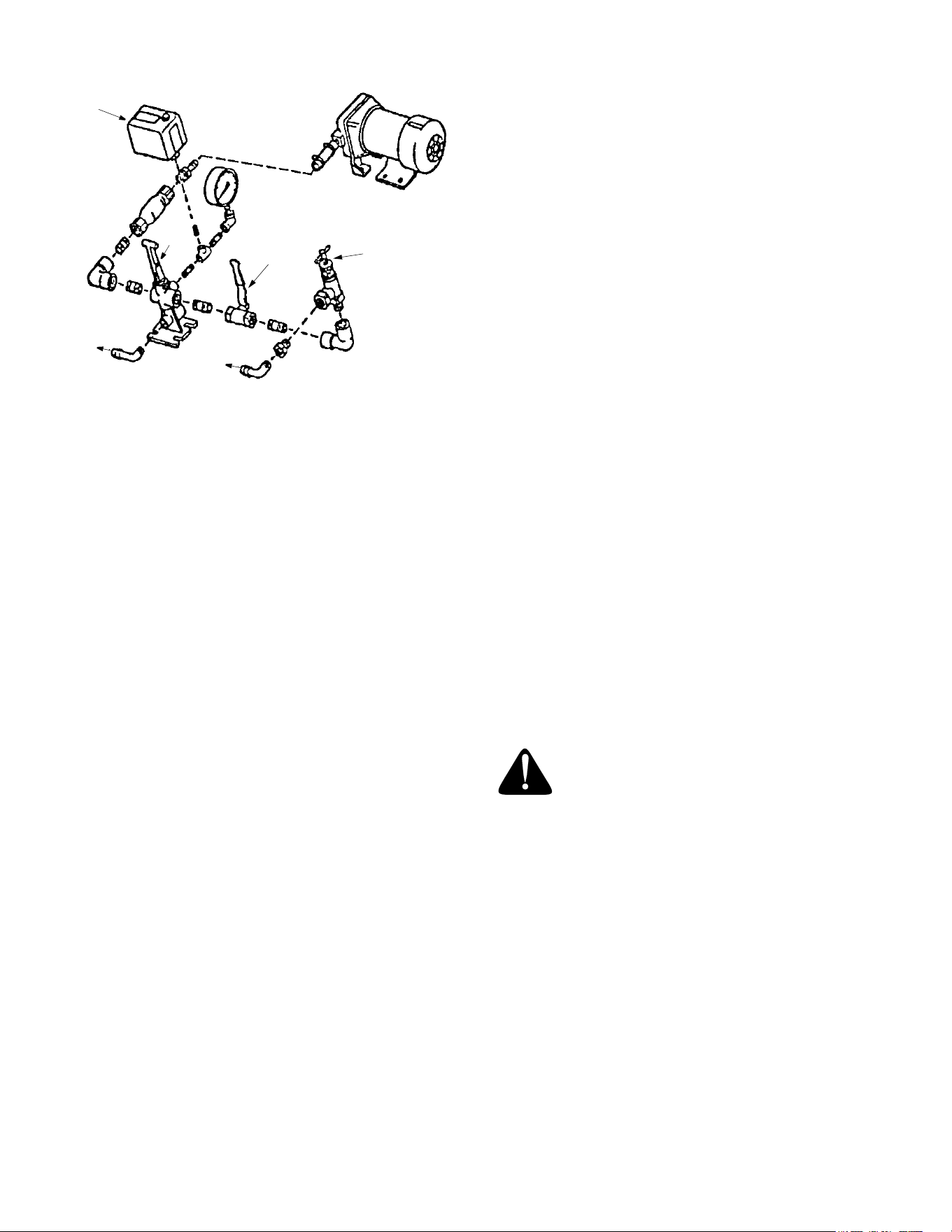
d.To use the calibration gauges:
The calibration gauges provide a series of “steps”, num-
bered in 1/32-inch increments, that will allow you to
“fine-tune” the spreader. Once you have calibrated your
rotary spreader for the product chosen, open the operat
-
ing lever and insert the calibration gauges until you
determine which step fits tightly into one of the open
holes in the hopper bottom. Record that step number for
future reference when using that product. You may
choose to set other rotary spreaders for application of
the same product by adjusting the shut off plate to that
calibration gauge step. This will provide consistent set
-
tings for all of your spreaders. To recalibrate your rotary
spreader after a period of use, adjust the rate control
arm to the "24" position. Open the operating lever and
insert the even-numbered Calibration Gauge into one of
the open holes in the hopper bottom. Close the operat
-
ing lever and let the shut off plate on the underside of
the hopper make contact with the number 10 step on the
Calibration Gauge. Move the rate control arm back
toward the "6" position until the bottom of the arm makes
contact with the shut off plate. If your spreader is prop
-
erly adjusted, the top of the rate control arm should be at
setting "10". To correct variances, remove the rate con
-
trol arm, place the bottom of the arm (up to the bolt hole)
in a vise, and bend either to the right or the left.
e.Spreader tips:
1. Always close the operating lever before filling the hop-
per.
2. Be sure the screen is in place to prevent lumps or
paper scraps from plugging the holes in the hopper bot
-
tom.
3. Always start traveling forward before opening the
operating lever; close the operating lever before forward
motion is stopped.
4. Empty the spreader after each use. Wash the
spreader thoroughly and allow it to dry. Keep the impel
-
ler clean.
4 mph 5 mph 6 mph 7 mph 8 mph
20 psi, five Tee-Jet TF-VS2 tips in CP25600 - NYR Quick Tee-Jet caps
Output
1.17 gal/min………………………………………………..
gal/acre
17.4 13.8 11.6 10.1 8.7
gal/1000 ft
2
2.0 1.6 1.4 1.2 1.0
25 psi, five Tee-Jet TF-VS2 tips in CP25600 - NYR Quick Tee-Jet caps
Output
1.46 gal/min………………………………………………..
gal/acre
21.7 17.3 14.5 12.6 10.9
gal/1000 ft
2
2.5 2.0 1.7 1.5 1.3
30 psi, five Tee-Jet TF-VS2 tips in CP25600 - NYR Quick Tee-Jet caps
Output
1.75 gal/min………………………………………………..
gal/acre
26.0 20.8 17.4 15.2 13.0
gal/1000 ft
2
3.0 2.4 2.0 1.8 1.5
Note:
The above values are based on manufacturer's information, and actual
values may vary based on chemical additives, temperature, as well as
system cleanliness and wear.
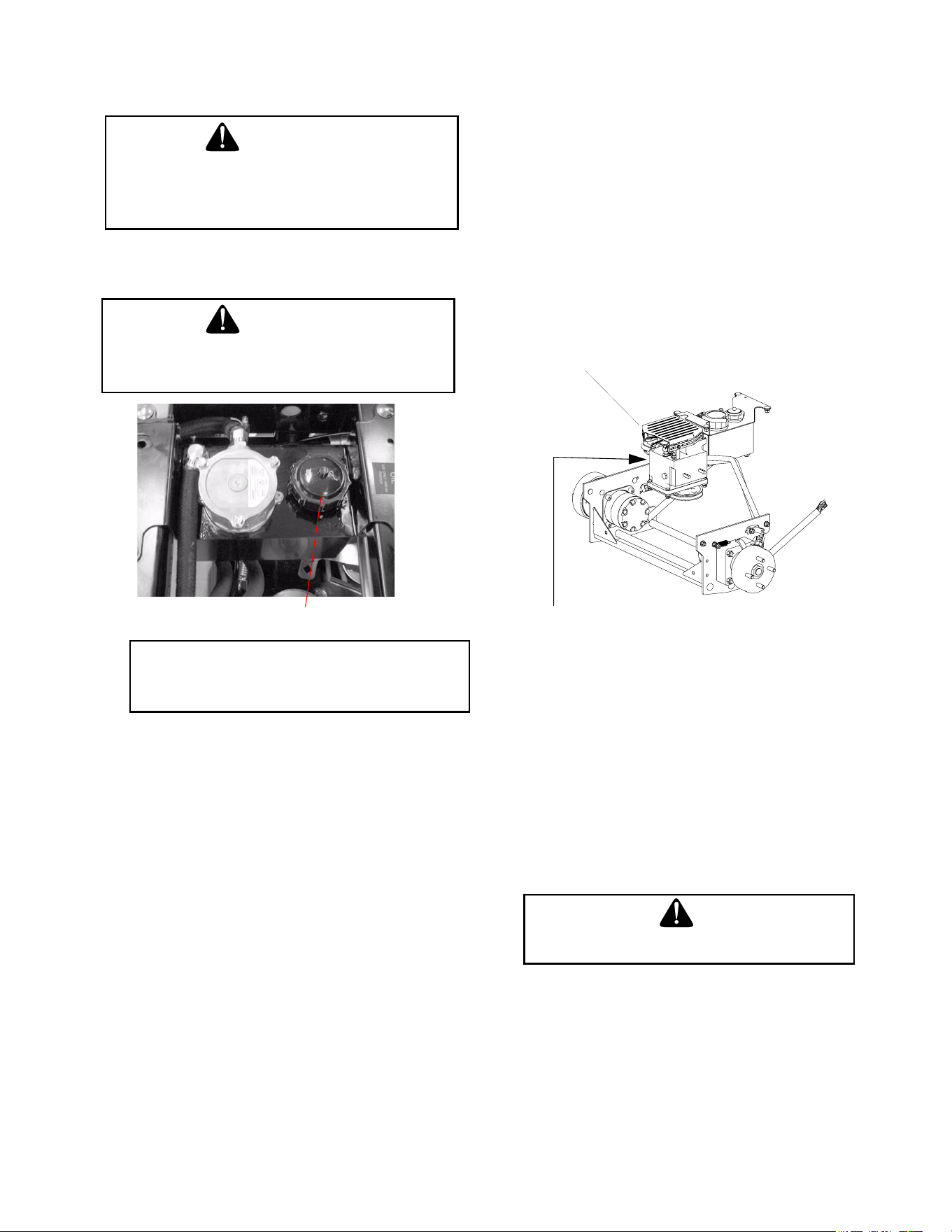
21
MAINTENANCE AND
SERVICE
WARNING:
Disconnect the spark plug wires or remove the
key from the ignition to prevent the engine from
accidentally starting before performing any main
-
tenance on this mower.
A.Hydraulic Oil
WARNING:
Never overfill the hydraulic units. Damage can
occur if the oil level is not within the proper oper
-
ating range.
Hydraulic Tank
Figure. 5
Note: When adding hydraulic oil, do so in small
quantities and recheck the oil level before adding
more. It is important that you do not overfill the
reservoir.
1. Adding Hydraulic Oil
(use SAE15W 40)
a. Place the Machine on a level surface and
engage the parking brake.
b. Stop the engine and remove the key from
the ignition switch.
c. Clean the area around the Hydraulic Oil fill
neck.
d. Remove the hydraulic fill cap and check the
level. The correct level is up to the lowest hole
of the oil tank fill neck.
e. Pour hydraulic oil into the reservoir up to the
lowest hole in the oil tank fill neck, if neces
-
sary.
2. Draining Hydraulic Oil
Used hydraulic oil must be disposed of properly. Do not pour it
down a drain or sewer, or dump it on open land, this creates an
environmental hazard. Please be aware of the environment
when disposing of used oil.
a. Place the Machine on a level surface and
engage the parking brake.
b. Stop the engine and remove the key from the
ignition switch.
c. Raise the seat forward to expose the hydraulic
oil fill point.
d. Clean the area around the hydraulic fill oil
cap.
e. Remove hydraulic fill oil cap.
f. Place a suitable container (at least 2 gallon)
under the hydraulic reservoir and filter.
g. Remove the hydraulic filter to allow hydraulic
oil to drain. Remove the drain plug from the
bottom of the hydraulic oil tank to drain.
Replace the plug.
h. Place a small pan under the pump motor
frame. Remove fill oil cap from hydraulic res
-
ervoir for faster drainage. Remove nut caps
and drain oil from both left and right pumps.
Replace and retighten nuts.
Figure. 6
Hydraulic pumps
Unfasten hose and drain
from this side of both pumps.
i. Remove the three screws from the top of the
oil filter and replace the oil filter element. Coat
the sealing surface with Shell Rimula 15W40
oil or equivalent. Install the three screws back
into the oil filter.
j. Add proper amount of hydraulic oil to reser-
voir.
k. Run and purge pumps and motors. Check oil
level.
l. Add proper amount of hydraulic oil to reser-
voir and repeat step k.
B.Electrical Circuit
Danger:
Read General Safety Precautions Nos. 9 and 10.
1.
Battery:
The battery is located beneath the
operator’s seat. Remove the fillcaps and check
the level of the liquid electrolyte in the battery
every 50 operating hours. If the level in any of the
six cells has dropped below the bottom of the
split ring inside the fill hole, refill the cell with dis
-
tilled water. To keep the outside of the battery
clean, brush on a strong solution of bicarbonate
of soda and water and rinse with clean water.

22
Keep the contacts and cable ends clean with a
wire brush and make sure the connections are
tight. Coat the terminals with petroleum jelly to
prevent corrosion.
2.
Battery Storage:
When storing the Machine for
long periods of time the following guidelines
should be taken.
a. Disconnect the battery cables from the termi-
nals and remove the battery. You will have to
remove the control panel to access the bat
-
tery strap. Replace control panel.
b. Clean the battery before storing. A dirty bat-
tery will lose its charge over time.
c. Store the battery with a full charge. A dis-
charged battery will freeze (refer to the table
below).
Specific Gravity Freezing Temp (°F)
1.265 -71
1.250 -62
1.200 -16
1.150 5
1.100 16
d. Recharge battery when ever the specific grav-
ity value is less than 1.225
3. Battery Removal
Warning:
When removing the cables from the battery follow
these steps to avoid a short between the wrench
and the frame.
a. Remove the Negative (black) cable.
b. Remove the Positive (red) cable.
c. Release the hold down straps.
d. Remove the battery without tipping.
4. Installing the Battery
Note: The battery is delivered from the factory
fully charged and filled with electrolyte.
a. Attach the Positive (red) cable.
b. Attach the Negative (black) cable.
c. Attach the rubber battery strap.
5. Jump Starting
Warning:
Failure to use this starting procedure can cause
sparking, and the gases in the battery to explode.
a. Attach the end of the red jumper cable to the
Positive terminal (+) of the charged battery.
b. Attach the other end of the red jumper cable
to the Positive terminal (+) of the low charge
battery.
c. Attach the end of the black jumper cable to
the Negative terminal of the charged battery.
d. Attach the other end of the black jumper cable
to the frame of the unit with the low charge
battery.
6.
Fuses:
There is one fuse located in the wiring
between the ignition and start switch and other
electrical components. This is a standard plug-in
type automotive fuse rated at 20 amp.
7.
Safety Switches:
There are five safety switches
in the electrical circuit which control the engine.
They are (1) the main power switch, (2) the park
-
ing brake switch, (3) the left and (4) the right
steering lever switches and (5) the seat
switch.They operate so that in order to start the
engine, the main power switch must be off, the
parking brake must be engaged, and both steer
-
ing levers must be opened-out to the side in the
neutral position. Once the engine is started, the
seat must be occupied and the parking brake
must be released before either of the steering
levers is folded up to the operating position or the
engine’s electronic ignition will be grounded out
and the engine will stop. Also, the seat must be
occupied before the main power switch can
cause the spreader and sprayer to operate.
8.
Safety Switch Operation Checks:
The following
operational checks should be made daily.
a. Main Power Switch: Sit in the operator’s
seat. With both steering levers opened-out in
the neutral position and the parking brake
engaged, turn the main power switch “on” and
try to start the engine. The engine should not
start. If it does, the main power switch must be
replaced. If the engine does not start, turn the
main power switch “off” and start the engine.
Now turn the main power switch “on” and the
power should be available for the spreader
and sprayer. If the power is not available, the
main power switch must be replaced, the seat
switch must be replaced or the spreader &
sprayer switch must be replaced.
b. Parking Brake Switch: Sit in the operator’s
seat. With both steering levers opened-out in
the neutral position and the main power
switch “off”, release the parking brake and try
to start the engine. The engine should not
start. If it does, the parking brake switch must
be repositioned or perhaps replaced. If the
engine does not start, engage the parking
brake and start the engine. Swing one steer
-
ing lever up to the operating position and the
engine should stop. If the engine does not

23
stop, the parking brake switch must be repo-
sitioned or replaced.
c. Left and Right Steering Lever Switches:
Sit in the operator’s seat. With both steering
levers opened-out in the neutral position, the
parking brake engaged and the main power
switch “off”, swing the left steering lever up to
the operating position and try to start the
engine. The engine should not start. If it
does, the left steering lever switch must be
repositioned or perhaps replaced. Open the
left steering lever to the neutral position and
swing the right steering lever up to the oper
-
ating position and try to start the engine. The
engine should not start. If it does, the right
steering lever switch must be repositioned or
perhaps replaced. If the engine does not
start, Open the right steering lever to the
neutral position and start the engine. Swing
the left steering lever up to the operating
position and the engine should stop. If the
engine does not stop, the left steering lever
switch must be repositioned or replaced.
Open the left steering lever out to the neutral
position and start the engine. Swing the right
steering lever up to the operating position
and the engine should stop. If the engine
does not stop, the right steering lever switch
must be repositioned or replaced.
d. Seat Switch: With both steering levers
opened-out to the neutral position, the park
-
ing brake engaged and the main power
switch in the “off” position, start the engine.
Now release the parking brake, hold down on
the back of the operator’s seat against spring
pressure, and swing one of the steering
levers up to the operating position. Release
the operator’s seat and the engine should
stop. If the engine does not stop, the seat
switch must be replaced. With both steering
levers folded out in the neutral position, the
parking brake engaged and the main power
switch in the “off” position, sit in the opera
-
tor’s seat and start the engine. Turn the main
power switch to the “on” position and the
power should be available for the spreader
and sprayer. Raise up slightly off the opera
-
tor’s seat and power should be discontinued
at the spreader and sprayer. If power is not
discontinued when you dismount from the
operator’s seat, the seat switch must be
replaced.
C.Tires
The two front wheels are caster wheels that are free to
swivel to accommodate the direction of the Machine.
The two rear wheels are used to propel the Machine in
the direction of input from the drive handles. Inflation
pressure of the rear tires is important for stability while
the Machine is in operation. If the tire diameter is not
equal between the two tires, the Machine will pull to one
side.
1.
Inflation Pressure:
a. Traction Tires—20 psi max; 8-10 psi recom-
mended
b. Front Caster Wheel—28 psi max; 20-25 psi
recommended
Use the Following guidelines for maintaining the tires:
a. Balance inflation pressure between the rear
tires to help maintain straight travel (see tire
side wall for proper inflation pressure).
b. Keep the valve caps tightened to prevent air
pressure loss.
2.
Leaking Tires:
When a flat tire occurs, repair or
replace immediately. The normal procedure is to
remove the wheel and replace it with a spare.
Take the leaking tire to a maintenance area and
repair. If a tire is getting soft, park the mower on
the nearest level, paved area. If the leaking tire
is on a traction wheel, put blocks on each side
of the opposite traction wheel and jack up the
tire that leaks about an inch off the ground.
Loosen and remove the lug nuts and remove
the wheel. Mount a spare wheel and tire,
replace the lug nuts, and using a torque wrench,
tighten them to 60
±
10 ft-lbs.
If the leaking tire is on a front caster wheel,
block both traction wheels and raise the caster
wheel so that the tire is an inch off the ground.
Loosen and remove the locknut from the axle
assembly and pull the axle assembly from the
caster yoke. The wheel and two spacer sleeves
will drop free. Slip the axle assembly through
one side of the caster yoke, through a spacer
sleeve, a spare wheel, the other spacer sleeve
and finally through the other side of the caster
yoke. Then tighten the locknut on the end of the
axle assembly.
Lower the machine off the jack and continue to
use. The wheel with the leaking tire should be
taken to the maintenance area, the tire inflated
to 20 psi and the wheel placed in a large bucket
of water. Carefully inspect the tire, rim and
valve for escaping air bubbles which indicate a
leak. Mark each leak with a yellow marking
crayon and then deflate the tire to 8 psi and
repeat the inspection. If the leaks you find are
pin hole size to 1/16" diameter, the tire can be
repaired using an aerosol can of tire inflater and
latex sealer available from any auto supply
store. Follow the directions on the can. If the
leaks are larger than 1/16" diameter, the tire
can be repaired with rubber plugs also available
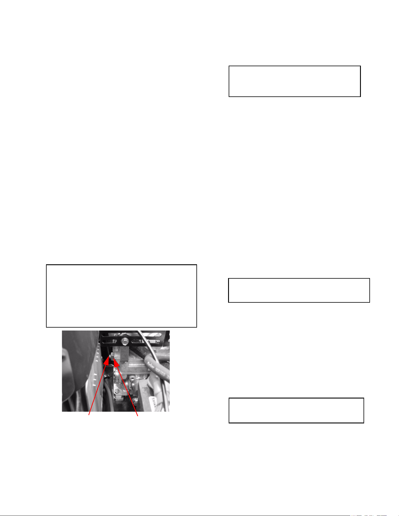
24
in a kit from any auto supply store. If the tire
bead is damaged, a tube will have to be installed
in the tire or the tire will have to be replaced.
3.
Creeping:
Creeping is the slight forward or back-
ward movement of the machine when the throttle
is on and the lapbars are in the opened-out posi
-
tion. If your machine creeps do the following.
a. Jack up rear of unit.
b. Place Lapbars in neutral opened-out position.
c. Locate jam nuts. (Reference control assembly
in parts list).
d. Loosen jam nuts on both ends of rod connec-
tors. See Control Assembly in the Illustrated
Parts Book (ONLY if machine creeps.)
e. Start unit and push throttle all the way on.
f. If unit creeps forward rotate rear rod connec-
tors counter-clockwise. And if unit creeps in
reverse, rotate clockwise.
Adjust the appropriate rod connector. The left
rod for the left side of the machine and the
right rod for the right side of machine.
Afterward, retighten jam nuts.
D. Brakes
While the machine is in motion, all braking is performed
dynamically through the hydraulic pumps and traction
motors, controlled by the two steering levers. When the
machine is parked with the engine shut off, the hydraulic
system locks the traction wheels.
Note: To move the mower forward or in reverse by
pushing, you must release the dynamic braking.
Locate the valves on the pump. Using a 15mm
wrench, loosen jam nut, then loosen the inner bolt
with an 8mm wrench (1/2 turn). There are two by-
pass valves, one for each pump. After pushing the
mower to the desired location, return both valves to
the operating position by turning the bolt clockwise,
but do not overtighten(See photo below)
Jam Nut, 15mm
Inner bolt, 8mm
View looking from Trim Side of Mower
.
When the machine is parked with the engine running and
the steering levers opened out in the neutral position, the
parking brakes should be applied. The parking brakes
are drum-type brakes mounted on each traction
wheel.They are both engaged by the same operating
lever.
1.
Adjustments:
The parking brake handle is an
overcenter lever that should engage with moder
-
ate force.
Note: To increase parking brake capacity
tighten the brake rods connected to the brake
arms equally. Tighten rods one full turn and
check parking capacity. Repeat Step.
To adjust either brake individually, disconnect the brake
rod from the brake arm by removing the cotter pin from
the clevis pin and pulling the clevis pin from the brake
clevis. Loosen the hex nut and turn the brake clevis in a
clockwise direction one full turn looking down the brake
rod. This will tighten the brake about .040 inch. Tighten
the hex nut and reassemble the brake clevis to the brake
shaft assembly. Normally, both brakes should be
adjusted and equal amount.
2.
Repair:
The machine is equipped with internal
drum brakes and will not normally require main
-
tenance. If they are not working properly, please
contact your service center.
E. Hydraulic System
1.
Hoses:
Check the hoses from the hydraulic oil
tank to the oil filter to the hydraulic lines daily for
leaks or abrasion and replace any damaged
hoses. Make certain there are no kinks or twists
in any hose.
2.
Hydraulic Oil Tank and Filter:
Note: Change the hydraulic oil and the oil filter
after the first 50 hours of operation and every 500
hours thereafter.
To drain the hydraulic oil tank, place a 2 gallon drain pan
under the drain plug on the bottom of the hydraulic oil
tank. Remove the drain plug, drain the tank, then replace
the plug. Place the drain pan under the filter and remove
the filter by unscrewing in a counterclockwise direction.
The filter will be full of oil, so empty it into the drain pan.
You don’t have to drain the rest of the hydraulic system.
Fill the replacement filter with a good grade of 15W-40 oil
and lubricate the sealing surface. Screw the filter onto
the filter base until it seats and then another one-half turn
to seal.
Note: Always wipe off the hydraulic tank fill
cap and the area around it before removing the
cap to prevent dirt from contaminating the oil.
Remove the fill cap and fill the tank with the same 15W-
40 oil selected for the filter until the oil level is up to the
level of the second hole in the fill tube. Leave this air
space for expansion. Start the engine and let it run at Lo-
idle for about five minutes. Check the filter for leaks.
Idling the engine and the pumps in this way will purge
any air from the system. Shut off the engine and recheck

25
the oil level in the tank. Top-off if necessary until the oil
level is up to the second hole in the fill tube.
Note: After unit is up to operating temperature,
turn off engine and re-check hydraulic oil. If oil
appears foamy or contains excessive air bubbles,
DO NOT OPERATE UNIT. Contact service techni-
cian.
3.
Hydrostatic Pumps and Motors:
The pumps
are the hardest-working components in the
hydraulic system. They are in operation all the
time the engine is running. Because of extremely
close tolerances, wear is an important factor in
their life.
Contaminants
in the hydraulic oil and
cavitation
does the greatest harm to the pumps.
Cavitation is a blockage in the supply lines that
produces a partial vacuum causing violent bub
-
bling in the hydraulic oil in the pump.
Check the two suction hoses (the hoses con-
nected to the filter) daily before starting the
engine. Look for a flattened condition or any
leaks and repair or replace as necessary. A flat
-
tened or leakng suction hose will permit cavita-
tion to develop which can destroy the pumps in a
short time.
Contaminants or foreign matter in the oil will also
damage the pumps . To prevent this, use a filter
that captures particles as small as 30 microns or
30 millionths of a meter in diameter. You can help
in the battle against dirt by being very careful
when you remove or repair a component in the
hydraulic system. Thoroughly clean off any com
-
ponent before you work on it. Plug the ends of
any hose or line you remove with a rubber or
plastic plug. Use plastic caps to seal off the ends
of hydraulic fittings. Place any component you
remove in a clean plastic bag so it can’t pick up
dust or dirt. Clean your hands frequently when
working on the hydraulic components.
Note: The pumps are not owner-repairable. If a
pump fails, contact your Service Center. Do not
disassemble the pump.
4.
Steering Lever Adjustments:
Place the
machine on level ground with the engine running,
parking brake off and steering levers opened out
to the neutral position. If the Machine begins to
creep, adjust the Steering Levers.
If the machine creeps, first determine whether it
creeps to the right or left side and which direction
the machine moves — to the front or the rear. To
make the adjustment, place the steering levers in
the opened-out neutral position and set the park
-
ing brake, shutoff the engine, take the key from
the ignition switch and pivot the seat forward. If
the machine creeps to the right, you will adjust
the linkage on the left side of the machine and
vice-versa. Remove the cap screw and lock
washer that secure the linkage control arm rod
end bearing to the control lever pivot. Loosen the
jam nut which prevents the rod end bearing from
turning. If the mower creeps forward, thread the
rod end bearing one-half turn clockwise into the
linkage control arm. If the machine creeps back
-
ward, thread the rod end bearing one half turn
counterclockwise out of the linkage control arm.
Then tighten the jam nut and reconnect the rod
end bearing to the control lever pivot by replacing
the cap screw and lock washer.
After adjusting the steering linkage, swing the
seat back to its normal position and place the
steering lever on the side you adjusted up to the
operating position. If you feel a slight push for
-
ward or a slight pull backward from the neutral
position you must adjust the lever return assem
-
bly. To do this, swing the steering lever back out
to the neutral position, pivot the seat forward and
loosen the jam nut on the lever return rod where
it is threaded into the hex-shaped end of the lever
return bolt. If the steering lever was pushed for
-
ward, turn the hex-shaped lever return bolt clock-
wise one-half turn off of the lever return rod. If the
steering lever was pulled back, turn the hex
shaped lever return bolt counterclockwise one-
half turn onto the lever return rod. Then tighten
the jam nut, pivot the seat back into the operating
position and start the machine to check that your
adjustments were made correctly.
F. Storage
1.
General:
If your machine will not be in service for
a few months, it should be stored in a dry loca
-
tion that is not subject to drastic changes in tem-
perature. Before storing, the following
maintenance procedures should be performed.
a. Clean the machine. The entire unit should be
washed and cleaned.
b. Protect the metal surfaces. Repair scratches
with the appropriate touch-up spray paint.
Brush a rust preventive oil on any unpainted
surfaces. (Be careful not to get any oil on the
drive belts.)
c. Lubricate the machine.
d. Drain the engine oil. The engine should be
warm so that all the oil drains. Replace the
engine oil filter and refill the crankcase with
fresh oil.
e. Gasoline Engine: Drain all the fuel. Close the
fuel tank shutoff valve. Disconnect the fuel
line from the carbuetor and put the end into an
approved fuel container. Open the fuel tank
shutoff valve and drain the fuel tank and line
into the approved container. Replace the fuel
line on the carburetor. Start the engine and
allow it to run out of fuel. This will prevent gum

26
and varnish deposits from forming. Replace
the fuel filter.
f. Gasoline Engine Only: Remove the spark
plugs and pour approximately one ounce of oil
into each cylinder. Crank the engine one or
two turns to spread the oil evenly on the cylin
-
der walls. Replace the spark plugs.
g. Clean the battery and make sure it is fully
charged.
h. Inspect the hydraulic hoses, lines and fittings.
Replace as necessary.
i. Jack the machine up and store it on blocks to
take the weight off of the tires.
2. To Put the Machine Back in Service:
a. Check the battery. Charge if necessary.
b. Gasoline Engine Only: Remove the spark
plugs and wipe them off. Using the starter,
crank the engine to pump the excess oil out of
the spark plug holes. Replace the spark plugs
and the ignition leads. Refill the fuel tank with
fresh gasoline.
c. Check the level of the oil in the crankcase and
the hydraulic tank.
d. Lower the machine off the block and check the
tire pressure.
e. Push the machine outdoors and start the
engine. Let the engine idle until it has warmed
up completely (4 to 5 minutes).
G. Pump
Diaphragm pumps require very little maintenance. The
procedures that are required are listed in the pump
Installation/Operation Instructions furnished with the
sprayer.
H. Tank
The sprayer tank requires no scheduled maintenance.
The inside of the tank should be flushed out after each
use as described in the section on Cleaning the
Sprayer. The outside of the tank should be hosed off
after use and scrubbed occasionally with soapy water to
remove ground-in dirt. If the tank is ever accidentally
punctured, it can be repaired with a Poly Patch Kit.
I. In-Line Strainer
The in-line strainer should be cleaned each day after the
sprayer has been flushed. Place a flat pan under the
strainer bowl to catch the liquid and unscrew the bowl.
Note: There is a washer-like seal between the top lip of
the bowl and the strainer body. This seal will sometimes
come off on top of the bowl or will drop out of the
strainer body when the bowl is unscrewed. DO NOT
LOSE THIS SEAL! It must be installed or you won't be
able to operate your sprayer.
J. Hose
If the hose on your sprayer is treated carefully, it will give
long and trouble free service. When you have finished
spraying a lawn, carry the application device and drag
the hose back to the sprayer. This protects the applica
-
tion device from being damaged by being dragged
through the turf and permits you to insure, as you walk
back to the sprayer, that the hose is not snagged on
something or wrapped around a tree. It also eases the
load on your reel because the hose will be rewound from
only half the distance. The hose should be flushed out
daily as described in the section on Cleaning the
Sprayer. Weekly, you should clean off the outside cover
of the hose by rewinding it onto the reel while gripping it
lightly with a rag dipped in soapy water.
K. Storage and Winterizing
If the sprayer will not be used for 30 days or more it
should be thoroughly flushed out and cleaned as
described in the section on Cleaning the Sprayer. The
engine should be drained of fuel to prevent gum
deposits from forming on essential carburetor parts.
First, the fuel tank should be drained and then the
engine should be started and allowed to run until it
stops from lack of fuel. While the engine is still warm,
the oil should be drained from the crankcase and then
the crankcase refilled with fresh oil. The spark plug
should be removed, a teaspoon of oil poured into the
cylinder, the engine cranked slowly to distribute the oil
and the spark plug replaced. The blower housing
should be removed and any dirt should be cleaned from
the engine's cooling fins. You should change the oil in
the pump every 200 hours and at the end of the
spraying season. You should change the pump's
diaphragms at the end of each spraying season. The
sprayer should be stored in a clean, dry area which
should be heated if freezing weather will occur during
the time of storage. If storing in a heated room is not
possible, winterize the sprayer. Pour a gallon of
antifreeze and a gallon of clean water into the sprayer.
Start the engine and agitate the mixture. Then pump the
antifreeze mixture through the plumbing and discharge
it from the application device back into two one gallon
containers. Store the 50/50 antifreeze mixture for future
use. If a boom is your application device, spray a small
amount of the antifreeze mixture from the boom and
then shut it off and drain the rest of the mixture from the
tank using the drain on the front of the sprayer.
L. Cleaning the Spreader
The spreader should be emptied and thoroughly
cleaned after each use.
Cover the motor and if pos-
sible clean the spreader hopper and working parts with
a high pressure water spray.
Do not spray water
directly on to the motor. The motor should be
cleaned by blowing it off with an air hose
(the motor
and gearbox are not waterproof.) Oil the latch-
arm pivots after each use.

27
MAINTENANCE SCHEDULE
A. Daily Checks
1. Before starting engine:
a. Check the fuel level.**
b. Check the engine oil level.**
c. Check the hydraulic oil level.
d. Check the hydraulic hoses for leaks, abra-
sion, kinks, twists, or a flattened condition.
e. Check the tires and tire pressure.
Drive Tires: 8-10 psi.
Front Caster Wheels: 20-25 psi.
f. Check the mower drive belt.
2. When ready to start the engine:
a. Check the five safety switches for proper
operation.
3. After use:
a. Clean the machine.
b. Clean the engine air screen.
c. Oil the wear points. Follow the Oiling
Chart.
d. After the first five hours, Change the
engine oil and engine oil filter.
B. Every 25 Hour Checks
1. Service the engine foam element air pre-
cleaner.*
C. Weekly or Every 50 Hour Checks
1. Change the engine oil. (Every 25 hours under
heavy duty operation.)
2. Clean or replace the engine’s paper air
cleaner element.*
3. Check the battery’s electrolyte level.
4. Clean the engine cooling fins and external
surfaces.*
5. After the first 50 hours, change the hydraulic
oil and the hydraulic oil filter. Change them
every 500 hours thereafter.
6. Oil wear points.
Follow the Oiling Chart.
7. Lubricate all grease fittings.
Follow the
Lubrication Chart.
D. Every 100 Hour Checks
1. Change the engine oil filter. (Every 50 hours
under heavy duty operation.)
2. Check the engine spark plugs.
E. Yearly Checks
Check the oil in the hydraulic reservoir.
* Perform maintenance more frequently under dusty
conditions.
**Reference Engine Owner’s Manual

28
.
OIL CHART
Apply a few drops of SAE 15W-40 engine oil or use a spray lubricant. Apply
the oil to both sides of pivot points. Wipe off any excess. Start engine and
operate mower briefly to insure that oil spreads evenly.
Number of Oil Points Description
WEEKLY
1
2
2
2
1
1
1
4
2
Seat Hinge
Steering Lever Linkage Rod End Bearings
Lever Return Assembly Rod End Bearings
Pump Control Lever Pivots
Brake Lever Pivot Clevis Pin
Brake Lever Control Rod Pivot
Brake Control Rod Swivel Joint
Brake Rod Clevis Pins
Brake Shaft Assembly Pivots
LUBRICATION CHART
Use a grease-gun filled with NO. 2 Multipurpose Lithium Base Grease
No. of Grease Fittings Description
WEEKLY
2
2
1
2
1
1
Front Caster Wheels
Front Caster Wheel Spindles
Axle Pivot
Steering Lever Pivots
Hydro Take-up Idler Pivot
Park Brake Pivot
Engine oil: Rimula 15W40 recommended or 10W40 engine oil rated SJ or higher.
Hydrostatic Fluid: Rimula 15W40 recommended.
Spindle Lubricant: Use only Shell Alvania RL 2 grease. This grease is an amber-colored grease
designed for high speed bearing applications. It has a base oil viscosity that reduces running losses, has been
formulated for low noise, has excellent corrosion protection, and has excellent bearing lubrication.
General Purpose Lubrication: Use any NLGI grade 2 multi-purpose grease. Shell Albida EP2 is rec-
ommended. Shell Albida EP 2 is a red-colored multi-purpose grease designed for heavy-duty bearing applica-
tions. It has high base oil viscosity for mechanical stability, has been formulated for high load, low-speed
applications, and has excellent lubrication and corrosion protection.
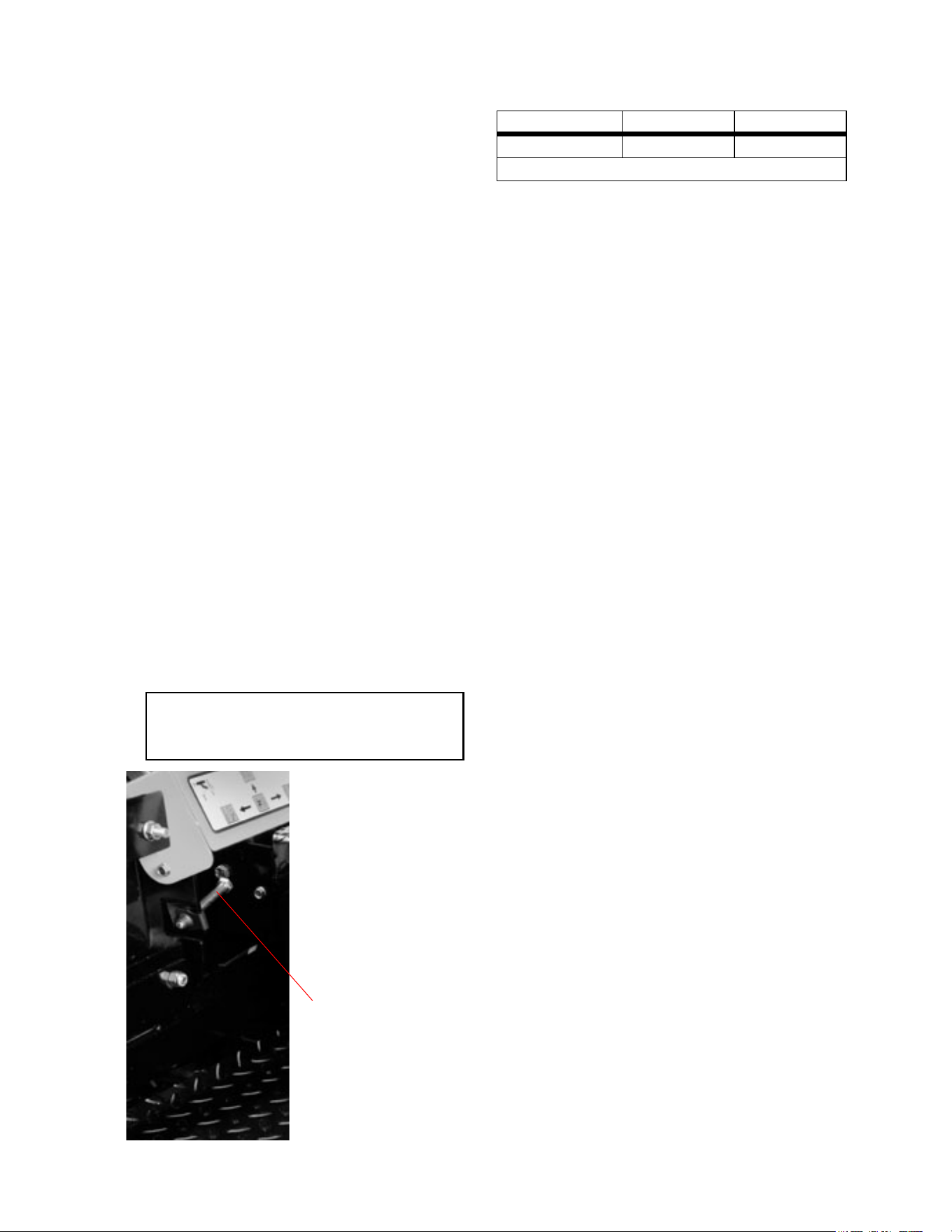
29
Performance Adjustments
A. High Speed Tracking Adjustment
If machine tracks to one side with both lap bars in fully
forward position:
1. Check air pressure in all four tires:
a. Pressure should be within specified ranges
and balanced side-to-side.
b. Rear tires 8-10 psi. recommended (20 psi
MAX.)
c. Front tires 20-25 psi. recommended (28 psi
MAX.
2. Check hydraulic fluid level (Ref. Engine
owner’s manual)
3. Verify that the machine does not creep when
the engine is running, the lap bars are in the
neutral position and the parking brake is
released. (Refer to section C-3 on page 24 of
this manual if this condition exists).
4. Recheck the tracking after any adjustments
based on the above.
5. If uneven tracking persists, adjust as follows.
(see Fig. 7)
a. Unit tracks to the RIGHT, adjust Left lap
bar stop bolt to make it longer.
b. Unit tracks to the LEFT, adjust Right lap
bar stop bolt to make it longer.
6. Re-check the tracking and make any fine tun-
ing adjustments to the lap bar stop bolts as
required.
Note: If stop bolt is adjusted too far, track-
ing problem will change sides. Make the fine
tuning adjustments by shortening the same
bolt.
Figure. 7
Lap Bar Stop Bolt
B. Enginge RPM Check and Adjustment
Description High RPM Spec. Low RPM Spec.
17 Hp Kawasaki 3600 +/-50 1550 +/-100
NOTE: RPM Specs. are for free running engines under no load.
1. Verify that the lap bars are in the neutral posi-
tion, the parking brake is on, and the PTO
drive is disengaged.
2. Start the machine and let it run at approxi-
mately half throttle for 3-5 minutes to bring the
engine up to operating temperature.
3. Locate the Hour Meter/Tachometer/ Service
Minder display on the right hand operator con
-
trol panel. (see Fig.1 on page 11 of the man-
ual) This display defaults to Tachometer mode
when engine is running.
4. Move the throttle lever to the high speed posi-
tion and note the RPM reading on the display.
5. Move the throttle lever back to the low speed
position and again note the displayed RPM’s.
6. Compare these noted RPM readings to the
specifications in Table 1, for the engine that is
on your machine.
7. If the readings do not correspond to the
ranges in the table, refer to the engine
owner’s manual for the proper adjustment pro
-
cedures.
8. If adjustments per the engine operator’s man-
ual do not result in proper RPM readings, con-
tact your service technician.
9. Note: The throttle cable sheath may shrink or
slip over time, changing the relationship
between the throttle lever on the left hand
operator control panel and the throttle arm on
the engine. To readjust the throttle cable:
a. Make sure the engine is off, place lap bars
in the neutral position, set the parking
brake, and disconnect and ground both of
the spark plug wires.
b. Locate and loosen the cable clamp on the
engine throttle plate.
c. Place the operator’s throttle lever to the
high speed position and then slide the
cable through the clamp until the throttle
arm is in the full throttle position. (Ref.
Engine owner’s manual)
d. Tighten the cable clamp.
e. Move the operator’s throttle lever between
high and low speed and verify that the
engine throttle arm also moves through it’s
full range of motion.
f. Repeat as required to obtain proper throt-
tle adjustment.
g. Verify proper throttle adjustment by check-
ing RPM readings as outlined above.
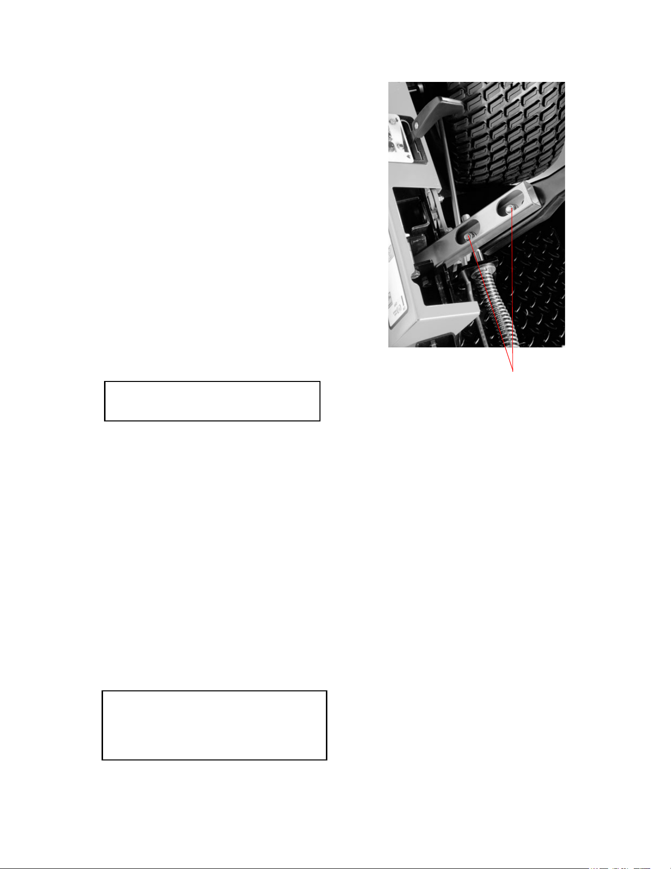
30
C. Lap Bar Adjustment
1. Proper lap bar and seat adjustment will result
in the following:
a. In the neutral position with hands on the
lap bars,
1. Operator’s upper arms should be relaxed
and approximately vertical.
2. Operator’s forearms should be approxi-
mately vertical.
b. In the full forward position,
1. Operator’s back should stay in contact
with the seat back.
2. Lap bars should not contact operator’s
legs.
c. In the full reverse position,
1. Lap bars should not contact the opera-
tor’s legs or torso.
2. Set the seat to the preferred operating position.
a. Adjustment lever is located under the front
edge of the seat.
b. The seat has five inches of front-to-rear
adjustment available.
3. Check factory settings of lap bars for the con-
ditions listed above.
Note: If lap bar adjustments are required,
height adjustments should be made prior to
angular adjustments.
4. To adjust the height of the lap bars,
a. Remove the nuts from the lap bar mounting
bolts (see Fig. 11).
b. Remove the bolts and lap bar and repostion
to the seconc set of holes in the mounting
block.
c. Replace the bolts and nuts and tighten to
28-34 ft-lbs.
1. If angular adjustments are also required,
nuts can be tightened until snug at this
point.
d. The same adjustments should be made to
both sides of the mower.
5. To adjust the front-to-rear angle of the lap bars,
a. Loosen the nuts on the lap bar mounting
bolts, leaving the bottom one fairly snug.
b. The top hole is slotted, allowing the lap bar
to pivot on the bottom bolt.
c. Move lap bar to the desired angle and
tighten the nuts to 28-34 ft-lbs.
Note: In the neutral position, the handles of
the lap bars should be aligned with approxi
-
mately a one inch gap between the tips. Adjus-
the gap by adding shim washers to the top
mounting bolt between the lap bar and the
mounting block.
d. Check the results of any adjustments to
the conditions described in section a,
above. Repeat any adjustment procedures
as required until all conditions are met.
Figure. 8
Lap Bar Mounting Bolt and Nuts

31
TROUBLESHOOTING GUIDE
PROBLEM CAUSE SOLUTION
Pump does not draw water. The in-line strainer is clogged. Clean the in-line strainer.
The suction line is plugged or collapsed. Examine the suction line.
Gate valve in suction line is closed. Open gate valve.
One or more valves are seating improperly. Examine the valve seatings and clean them
or replace if scored or worn.
Oil comes out of the dis-
charge port. One or more diaphragms are split.
Drain the pump of oil. Dismantle the heads
and replace the diaphragms. Refill the pump
with fresh oil.
The pressure gauge fluctu-
ates excessively
The pump is sucking in air somewhere in the
suction line.
Examine the suction line and make certain
all parts are firmly secured.
Air has not been entirely evacuated from the
pump.
Run the pump with the outlet hose open to
evacuate air from the pump.
The liquid flow is irregular. Incorrect charge In the pulsation damper. Check the charge in the pulsation damper.
(10% of working pressure.)
One or more valves are seating improperly. Examine the valve seatings and clean them
or replace them if scored or worn.
The output drops and the
pump is noisy.
The oil level is too low. Add oil to the correct level for the pump.
No agitation. Fiberglass sprayer - The agitator belt is
loose.
Tighten the agitator belt.
Poly sprayer -The ball valve to the agitator is
shut off or the line is plugged.
Open the ball valve to the agitator. Check
the line to the agitator.
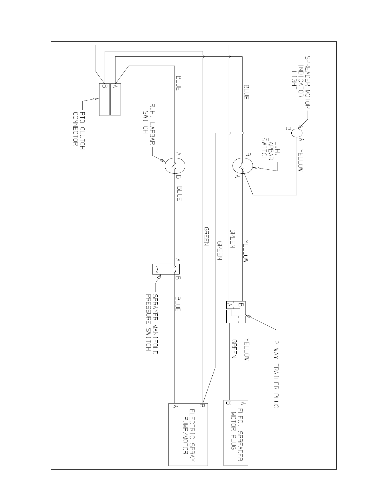
32
WIRING DIAGRAM
GD: 629-04168

33
This page intentionally left blank.

34
CALIFORNIA EMISSION CONTROL WARRANTY STATEMENT
YOUR WARRANTY RIGHTS AND OBLIGATIONS
The California Air Resources Board and MTD Consumer Group Inc are pleased to explain the evaporative emission control system warranty on your 2008 lawn
mower. In California, new lawn mowers must be designed, built and equipped to meet the State’s stringent anti-smog standards. MTD Consumer Group Inc must
warrant the EECS on your lawn mower for the period of time listed below provided there has been no abuse, neglect or improper maintenance of your lawn mower.
Your EECS may include parts such as the carburetor, fuel-injection system, the ignition system, catalytic converter, fuel tanks, fuel lines, fuel caps, valves,
canisters, filters, vapor hoses, clamps, connectors, and other associated emission-related components.
Where a warrantable condition exists, MTD Consumer Group Inc will repair your lawn mower at no cost to you including diagnosis, parts and labor.
MANUFACTURER’S WARRANTY COVERAGE:
This evaporative emission control system is warranted for two years. If any evaporative emission-related part on your equipment is defective, the part will be
repaired or replaced by MTD Consumer Group Inc.
OWNER’S WARRANTY RESPONSIBILITIES:
As the lawn mower owner, you are responsible for performance of the required maintenance listed in your owner’s manual. MTD Consumer Group Inc recommends
that you retain all receipts covering maintenance on your lawn mower, but MTD Consumer Group Inc cannot deny warranty solely for the lack of receipts.
As the lawn mower owner, you should however be aware that MTD Consumer Group Inc may deny you warranty coverage if your lawn mower or a part has failed
due to abuse, neglect, or improper maintenance or unapproved modifications.
You are responsible for presenting your lawn mower to MTD Consumer Group Inc’s distribution center or service center as soon as the problem exists. The
warranty repairs should be completed in a reasonable amount of time, not to exceed 30 days. If you have a question regarding your warranty coverage, you should
contact the MTD Consumer Group Inc Service Department at 1-800-800-7310.
GENERAL EMISSIONS WARRANTY COVERAGE:
MTD Consumer Group Inc warrants to the ultimate purchaser and each subsequent purchaser that the lawn mower is: Designed, built and equipped so as to
conform with all applicable regulations; and free from defects in materials and workmanship that cause the failure of a warranted part to be identical in all material
respects to that part as described in MTD Consumer Group Inc’s application for certification.
The warranty period begins on the date the lawn mower is delivered to an ultimate purchaser or first placed into service. The warranty period is two years.
Subject to certain conditions and exclusions as stated below, the warranty on emission-related parts is as follows:
1. Any warranted part that is not scheduled for replacement as required maintenance in the written instructions supplied, is warranted for the warranty period
stated above. If the part fails during the period of warranty coverage, the part will be repaired or replaced by MTD Consumer Group Inc according to subsection
(4) below. Any such part repaired or replaced under warranty will be warranted for the remainder of the period.
2. Any warranted part that is scheduled only for regular inspection in the written instructions supplied is warranted for the warranty period stated above. Any such
part repaired or replaced under warranty will be warranted for the remaining warranty period.
3. Any warranted part that is scheduled for replacement as required maintenance in the written instructions supplied is warranted for the period of time before the
first scheduled replacement date for that part. If the part fails before the first scheduled replacement, the part will be repaired or replaced by MTD Consumer
Group Inc according to subsection (4) below. Any such part repaired or replaced under warranty will be warranted for the remainder of the period prior to the
first scheduled replacement point for the part.
4. Repair or replacement of any warranted part under the warranty provisions herein must be performed at a warranty station at no charge to the owner.
5. Notwithstanding the provisions herein, warranty services or repairs will be provided at all of our distribution centers that are franchised to service the subject
engines or equipment.
6. The lawn mower owner will not be charged for diagnostic labor that is directly associated with diagnosis of a defective, emission-related warranted part,
provided that such diagnostic work is performed at a warranty station.
7. MTD Consumer Group Inc is liable for damages to other engine or equipment components proximately caused by a failure under warranty of any warranted
part.
8. Throughout the lawn mower warranty period stated above, MTD Consumer Group Inc will maintain a supply of warranted parts sufficient to meet the expected
demand for such parts.
9. Any replacement part may be used in the performance of any warranty maintenance or repairs and must be provided without charge to the owner. Such use will
not reduce the warranty obligations of MTD Consumer Group Inc.
10. Add-on or modified parts that are not exempted by the Air Resources Board may not be used. The use of any non-exempted add-on or modified parts by the
ultimate purchaser will be grounds for disallowing a warranty claims. MTD Consumer Group Inc will not be liable to warrant failures of warranted parts caused
by the use of a non-exempted add-on or modified part.

35
WARRANTED PARTS:
The repair or replacement of any warranted part otherwise eligible for warranty coverage may be excluded from such warranty coverage if MTD Consumer Group
Inc demonstrates that the lawn mower has been abused, neglected, or improperly maintained, and that such abuse, neglect, or improper maintenance was the
direct cause of the need for repair or replacement of the part. That notwithstanding, any adjustment of a component that has a factory installed, and properly
operating, adjustment limiting device is still eligible for warranty coverage. The following emission warranty parts are covered:
(1) Fuel Metering System
s#OLDSTARTENRICHMENTSYSTEMSOFTCHOKE
s#ARBURETORANDINTERNALPARTS
s&UELPUMP
s&UELTANK
(2) Air Induction System
s!IRCLEANER
s)NTAKEMANIFOLD
(3) Ignition System
s3PARKPLUGS
s-AGNETOIGNITIONSYSTEM
(4) Exhaust System
s#ATALYTICCONVERTER
s3!)2EEDVALVE
(5) Miscellaneous Items Used in Above System
s6ACUUMTEMPERATUREPOSITIONTIMESENSITIVEVALVESANDSWITCHES
s#ONNECTORSANDASSEMBLIES
(6) Evaporative Control
s&UELHOSECERTIFIEDFOR!2"EVAPORATIVEEMISSIONS
s&UELHOSECLAMPS
s4ETHEREDFUELCAP
s#ARBONCANISTER
s6APORLINES
'$/#2EV#

Cub Cadet LLC - P.O. Box 361131, Cleveland, Ohio 44136-0019; Phone 1-877-282-8684
MANUFACTURER’S LIMITED WARRANTY FOR CUB CADET COMMERCIAL
LAWN APPLICATION EQUIPMENT
IMPORTANT: To obtain warranty coverage owner may be required
present proof of purchase and applicable maintenance records to the
servicing dealer. Please see the operator’s manual for information on
required maintenance and service intervals. In addition, Cub Cadet
may deny warranty coverage if the hour meter, or any part thereof, is
altered, modified, disconnected or otherwise tampered with.
The limited warranty set forth below is given by Cub Cadet LLC with
respect to new merchandise used for commercial and related purposes
purchased and used in the United States and/or its territories and
possessions, and by MTD Products Limited with respect to new
merchandise purchased and used in Canada and/or its territories and
possessions (either entity respectively, “Cub Cadet”).
Cub Cadet warrants this product (excluding its No-Fault Components,
as described below) against defects in material and workmanship for a
period of one (1) year from the date of original retail purchase or lease
and will, at its option, repair or replace, free of charge, any part found
to be defective in materials or workmanship.
No-Fault Components include only belts, tires, and seats which are
warranted to be free from defects in material and workmanship for a
period of thirty (30) days from the date of original purchase or lease.
HOW TO OBTAIN SERVICE: Warranty service is available, WITH
PROOF OF PURCHASE AND APPLICABLE MAINTAINCE
RECORDS, through your local authorized service dealer. To locate the
dealer in your area;
In the U.S.A
.:
Check your Yellow Pages, or contact Cub Cadet LLC at P.O. Box
361131, Cleveland, Ohio 44136-0019, or call 1-877-282- 8684, or log
on to our Web site at www.cubcadetcommercial.com.
In Canada
:
For all provinces excluding Quebec contact Modern Power Products
d/o MTD Canada Ltd. At 60 Ottawa Street South, Kitchener, Ontario
N2G 3S7 or call 1-800-567-6775 or log on to our website at
www.cubcadet.ca.
In Quebec contact Les Distributions RVI Ltee. d/o MTD Canada Ltd.
2955 jean-Baptiste Deschamps, Ville Lachine, Quebec H8T 1C5 or
call 1-800-361-5770 or log on to our website at www.cubcadet.info.
This limited warranty does not provide coverage in the following cases:
a. Routine maintenance items such as lubricants, filters, tune-
ups, brake adjustments, clutch adjustments, control linkages,
drive system, engines, and normal deterioration of the exterior
finish due to use or exposure.
b. Service completed by someone other than an authorized
service dealer.
c. For products sold or exported outside of the United States
and/or Canada, and their respective possessions and
territories, except those sold through Cub Cadet’s authorized
channels of export distribution.
d. Damage or failure resulting from the use of defective or
improper peplacement parts and\or accessories other than
genuine Cub Cadet parts.
e. Transportation charges and service calls.
f. Failure to operate and maintain the product in accordance with
the Operator’s Manual furnished with the product,
g. Damages and failures resulting from misuse, abuse, neglect,
accident, improper maintenance, alteration, vandalism, theft,
fire, water, or damage because of other peril or natural
disaster.
There are no implied warranties, including without limitation any
implied warranty of merchantability or fitness for a particular
purpose. No warranties shall apply after the applicable period of
express written warranty above. No other express warranties
beyond those mentioned above, given by any person or entity,
including a dealer or retailer, with respect to any product, shall
bind Cub Cadet. The exclusive remedy is repair or replacement
of the product as set forth above. The terms of this warranty
provide the sole and exclusive remedy arising from the sale
and/or lease of the products covered hereby. Cub Cadet shall not
be liable for any incidental or consequential loss or damage
including, without limitation, expenses incurred for substitute or
replacement lawn care services or for rental expenses to
temporarily replace a warranted product.
Some jurisdictions do not allow the exclusion or limitation of incidental
or consequential damages, or limitations on how long an implied
warranty lasts, so the above exclusions or limitations may not apply to
you. This limited warranty gives you specific legal rights, and you may
also have other rights that vary in different jurisdictions.
In no event shall recovery of any kind be greater than the amount of
the purchase price of the product sold. Alteration of safety features
of the product shall void this warranty. You assume the risk and
liability for loss, damage, or injury to you and your property and/or to
others and their property arising out of improper use, misuse or
inability to use the product. This limited warranty shall not extend to
anyone other than the original purchaser/Leasee or to the person for
whom it was purchased or leased as a gift.
Form #769-03905 Rev. 08-0 03/04/2008

