

2in1 Laser Tape Measure
IMPORTANT:
Please read these instructions before operating the product.
A10 PRO

1. GENERAL SAFETY RULES
- 01 -
•
•
•
•
Store idle laser out of reach of children and other untrained persons. Lasers are dangerous in the hands of untrained users.
Do not use tool if switch does not turn it on or off. Any tool that cannot be controlled with the switch is dangerous and must be
repaired.
Do not use optical tools such as a telescope or transit to view the laser beam. Serious eye injury could result.
Do not place the laser in a position which may cause anyone to intentionally or unintentionally stare into the laser beam. Serious
WARNING: Read all instructions. Failure to follow all instructions listed below may result in hazardous radiation exposure, electric
shock, fire and/or serious injury.
SAVE ALL WARNINGS AND INSTRUCTIONS FOR FUTURE REFERENCE
The label on your tool may include the following symbols.
V
mW
nm
2
Volts
Milliwatts
Laser warning symbol
Wavelength in nanometers
Class 2 Laser
Do not operate the laser in explosive atmospheres, such as in the presence of flammable liquids, gases, or dust.Power tools create
sparks which may ignite the dust or fumes.
•

- 02 -
•
•
•
Keep your work area clean and well lit. Cluttered benches and dark areas invite accidents.
Do not operate laser tools in explosive atmospheres, such as in the presence of flammable liquids, gases, or dust.
Keep children and bystanders away while operating a laser tool.Distractions can cause you to lose control.
WORK AREA
• Stay alert, watch what you are doing and use common sense when operating a laser tool. Do not use tool while tired or under
the influence of drugs, alcohol, or medication. A moment of inattention while operating power tools may result in serious
personal injury.
PERSONAL SAFETY
•
•
Do not overreach. Keep proper footing and balance at all times. Proper footing and balance enables better control of the tool in
unexpected situations.
Use safety equipment. Always wear eye protection. Dust mask, non-skid safety shoes, hard hat, or hearing protection may be
required for appropriate conditions.
eye injury could result.
Do not position the laser near a reflective surface which may reflect the laser beam toward anyone’s eyes. Serious eye injury
could result.
Turn the laser off when it is not in use. Leaving the laser on increases the risk of staring into the laser beam.
Do not modify the laser in any way. Modifying the tool may result in hazardous laser radiation exposure.
Do not operate the laser around children or allow children to operate the laser. Serious eye injury may result.
Do not remove or deface warning labels. If labels are removed user or others may inadvertently expose themselves to radiation.
Position the laser securely on a level surface. Damage to the laser or serious injury could result if the laser falls
•
•
•
•
•
•

- 03 -
Do not place equipment and its accessories in the trash. Items must be properly disposed of in accordance with
local regulations. Please see epa.gov/recycle for addition
DISPOSAL / RECYCLE
•
•
•
Do not use tool if switch does not turn it on or off. Any tool that cannot be controlled with the switch is dangerous and must be
repaired.
Store idle tools out of reach of children and other untrained persons. Tools are dangerous in the hands of untrained users.
Use only accessories that are recommended by the manufacturer for your model. Accessories that may be suitable for one tool,
may become hazardous when used on another tool.
•
•
•
Tool service must be performed only by qualified repair personnel. Service or maintenance performed by unqualified
personnel could result in a risk of injury.
When servicing a tool, use only identical replacement parts. Follow instructions in the Maintenance section of this
manual. Use
of unauthorized parts or failure to follow Maintenance Instructions may create a risk of electric shock or injury.
SERVICE
TOOL USE and CARE
- 04 -
2in1 Laser Tape Measure
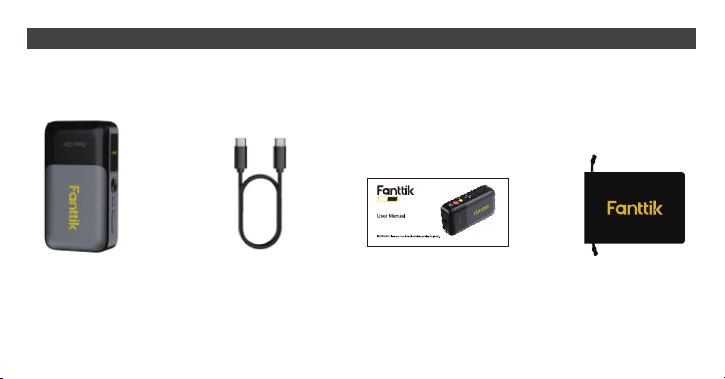
2. PACKAGE CONTENT
User manual x 1Charging Cable x 1Laser Tape x 1
Storage bag x 1
A10 PRO
- 05 -
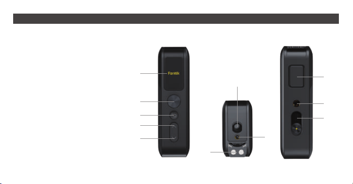
3. FEATURES DETAILS
IPS Display
Power Button
Return Button
Up Arrow
Down Arrow
Receiver Lens
Laser Window
Tape
Tape Lock Button
Copper Nut(1/4”-20)
Charging Port
1.
2.
3.
4.
5.
6.
7.
8.
9.
10.
11.
1
2
3
4
5
6
7
8
9
10
11
Figure A
- 06 -
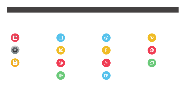
Figure B Figure C
Laser
Records
Settings
Dist. meas..
Vol. meas.
Bubble
Area meas.
Units
Offset
Orientation
Ref. plane
Brightness
Reset
Language
Figure D
4. MENU’S SYMBOL OVERVIEW

- 07 -
Button and function(See Figure A )
- Power Button (2)
•
•
•
Hold the button to power on/off.
Press to select the highlighted option or enter submenu.
Press to record the measurement value In tape measurement mode.
NOTE: After completing the selection with the arrows, if you wish to abandon the changes, press the return button; if you want to
confirm your selection, press the power button.
- Return Button (3)
•
•
Press to back to the previous menu.
Press the button to quit the operation before confirmed.
- Up Arrow (4)/Down Arrow (5)
•
•
•
Press to scroll up/down in menu options.
Press to turn it on/off if option is a switch.
Press to increase/decrease parameter to reach the desired preset value,
Primary Menu (see Figure B)
• Press power button to turn on the device, and the system will automatically access the primary menu. the interface has three
menu symbols:
5. OPERATION AND FUNCTION

- 08 -
Measurement Mode
Choose measure icon and press power button, then entering next interface, there are four measurement options to choose。
Tips: Press the up/down arrow keys to scroll to the desired mode, then press the power button to access the next-level menu.
Measure Mode Settings Mode Records Mode
WARNING:Failure to follow the guidelines below may result in inaccurate measurements or no reading at all.
•
•
•
Hold the device steady and avoid shaking during measurement.
Position the measured surface perpendicular to the laser for optimal accuracy.
Avoid measuring reflective surfaces (e.g., glass), as they may interfere with readings.
- Distance Measurement
•
•
•
•
To measure, press the power button. The measurement will be shown on the bottom of the
display.
Press the power button again, and the previous measurement will move to the middle line.
Press the power button for a new measurement on the bottom line.
Press the power button again, and the measurement from the middle line will move to the top
line, while the measurement from the bottom line will move to the middle line.

- 09 -
- Area Measurement
•
•
•
To measure the width and length one after the other, as with a length measurement.
The first measured value will be shown at the top of the display. The laser beam remains switched on between
the two measurements.
After the second measurement has been completed, the area will be automatically calculated and displayed. The
end result will be shown at the bottom of the display, while the current measured value will be shown above it.
- Volume Measurement
•
•
•
To measure the width, length, and depth one after the other, as with a length measurement.
The first measured value will be shown at the top of the display. The laser beam remains switched on between
the three measurements.
After the third measurement has been completed, the volume will be automatically calculated and displayed. The
end result will be shown at the bottom of the display, while the current measured value will be shown above it.
- Bubble Level
•
•
Activate the bubble level measurement function, place the device on the plane to be measured, and ensure the
surface is clean and flat to avoid affecting the measurement results.
Observe the angle readings on the display as shown in the figure on the right, which displays the angles in both
the X and Y directions.
14.5
13.5

- 10 -
Choose settings icon in primary manu(Figure B) and press power button , then entering next-level menu(Figure C)
- Changing the Unit of Measure
Select the “unit” in the settings menu.Unit of measure “ft” is set by default.Set the required unit of measure and confirm by
pressing power button,To exit the menu item, press the return button.
- Changing the Refer Plan of Measure
- Setting the Offset
Select the “offset” and press power button in the settings menu. press up/down arrow button to increase/decrease offset
value.Note: Offset settings only for distance compensation; errors could be caused to use it in normal scenarios!
- Setting the Orientation
Select the “Orientation” and press power button in the settings menu,
then press up/down arrow button turn on/off the switch, the icon indicates orientation is in the “on” state.
- Setting the Brightness
Select the “Brightness” and press power button in the settings menu,Set the required brightness by pressing up/down arrow
button to increase/decrease display Illumination then confirm by pressing power button .
6. SETTINGS MENU
Select "Ref. plan" and press the power button to enter the reference plane menu. You’ll see three options: Front Reference,
Center Reference, and Rear Reference. Choose your desired setting, then press the power button to confirm.

- 11 -
- Setting the Language
Select the “language” and press power button in the settings menu,.Set the required language and confirm by pressing power
button .
Memory Value Display or Delete
A maximum of 30 values can be retrieved.
Select the “Records” and press power button to entering a value list.
Except length values, a quick press of the power button lets you see the original measured values for area and volume. Holding the
power button opens a dialog box, giving you the option to delete a single record or clear all records.
- 12 -
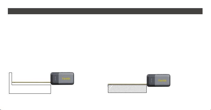
Figure E Figure F
1. Top Measuring (See Figure E)
With a movable magnetic hook, this tape ensures precise measurements by having the claw directly touch the target surface,
eliminating hook errors. It uses the tape's top as the zero point for accuracy.
2. Hook Measuring (See Figure F)
Hook the target and slide the ruler hook to the right to avoid hook errors. It still uses the tape's top as the zero point for accurate
results.
•
•
•
Press the power button to save the value after measurement.
Press lock button 9 to retrack the tape.
Press return button 3 to exit the tape measure display mode
Tips: When powered on, pull out the tape to activate the tape measurement mode on the display.
7. TAPE MEASURE OPERATION GUIDE
- 13 -
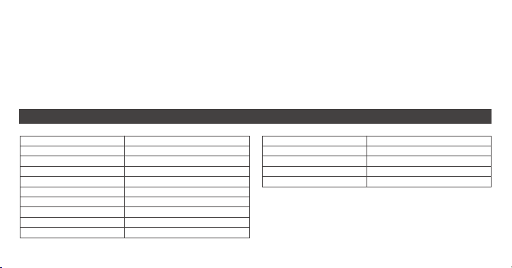
Laser Measuring Range
Tape Measuring Range
Distance Accuracy
Tilt Measurement Range
Angle Accuracy
Measure Function
Screen
Laser Class
Laser Type
Storage size
0.2-165ft(0.05-50m)
9.8ft(3m)
1/8in@30ft(3mm@10m)
±90°
±1°
Distance/Area/Volume/Level
1.47" IPS Color Screen
Class II, <1mW
630~670nm
30 Records
Auto Shutdown time
Operating Temperature
Storage Temperature
Storage Humidity
Battery
120 seconds
32°F-104°F(0°C-40°C)
-4°F-140°F(-20°C-60°C)
≤80%
3.7V 500mAh Lithium Battery
• Keep the tape measure level or straight to avoid tilting errors.
• Retract the tape after use to prevent damage.
Precautions
• Clean the tape regularly to avoid dust or dirt buildup.
• Avoid impacts or bending to maintain accuracy.
• Store in a dry place to prevent rust.
Maintenance and Care
8. SPECIFICATIONS
- 14 -
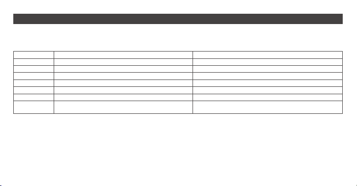
When the device displays "Err x," it indicates that the instrument may not be able to perform measurements correctly. Below are
possible error messages and their solutions.
Reflected signal is too weak.
Reflected signal is too strong.
Battery voltage is too low.
Memory error.
Temporary is overheating
Measurement range exceeded.
The length measurement result differs from the
correct value by a constant value.
Err 1
Err 2
Err 3
Err 4
Err 5
Err 6
/
Code Cause Corrective Measure
Use a reflector.
Test on a different reflective surface.
Charge the battery.
Return to repair.
Turn off the device and allow it cool down before reuse
Measure the distance within measurement
check if the setting of referance plan or offset is correct
9. TROUBLESHOOTING

- 15 -
Changes or modifications not expressly approved by the party responsible for compliance could void the user's authority to
operate the equipment. This equipment has been tested and found to comply with the limits for a Class B digital device,
pursuant to Part 15 of the FCC Rules. These limits are designed to provide reasonable protection against harmful
interference in a residential installation. This equipment generates uses and can radiate radio frequency energy and, if not
installed and used in accordance with the instructions, may cause harmful interference to radio communications. However,
there is no guarantee that interference will not occur in a particular installation. If this equipment does cause harmful
interference to radio or television reception, which can be determined by turning the equipment off and on, the user is
encouraged to try to correct the interference by one or more of the following measures:
- Reorient or relocate the receiving antenna.
- Increase the separation between the equipment and receiver.
- Connect the equipment into an outlet on a circuit different from that to which the receiver is connected.
- Consult the dealer or an experienced radio/TV technician for help.
This device complies with part 15 of the FCC Rules. Operation is subject to the following two conditions: (1) This device
may not cause harmful interference, and (2) this device must accept any interference received, including interference that
may cause undesired operation.
FCC WARNING STATEMENT
929-693-6066 MON-FRI 9AM-5PM(ET)
www.fanttik.com
METASEE LLC
12 GREENWAY PLZ STE 1161A HOUSTON, TX 77046-1203
