
Technical Support and E-Warranty Certificate www.vevor.com/support
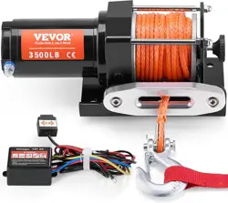
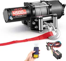
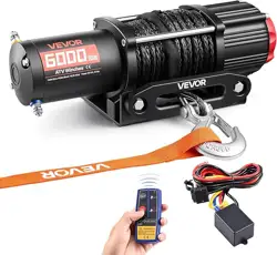
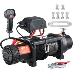
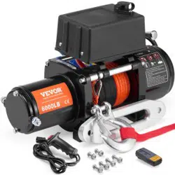
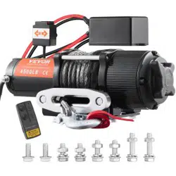
ELECTRIC WINCH
MODEL:P2000-1/P3000-1C/P4000-1D/P4000-1W
We continue to be committed to provide you tools with competitive price.
"Save Half", "Half Price" or any other similar expressions used by us only represents an
estimate of savings you might benefit from buying certain tools with us compared to the major
top brands and does not necessarily mean to cover all categories of tools offered by us. You
are kindly reminded to verify carefully when you are placing an order with us if you are
actually saving half in comparison with the top major brands.


- 1 -
MODEL: P2000-1/P3000-1C/P4000-1D/P4000-1W
Have product questions? Need technical support? Please feel free to
contact us:
Technical Support and E-Warranty Certificate
www.vevor.com/support
NEED HELP? CONTACT US!
This is the original instruction, please read all manual instructions
carefully before operating. VEVOR reserves a clear interpretation of our
user manual. The appearance of the product shall be subject to the
product you received. Please forgive us that we won't inform you again if
there are any technology or software updates on our product.
ELECTRIC WINCH
- 2 -
SAFE INSTRUCTIONS
WARNING: Read carefully and understand all ASSEMBLY AND
OPERATION INSTRUCTIONS before operating. Failure to follow the
safety rules and other basic safety precautions may result in serious
personal injury.
APPLICATION INFORMATIONN
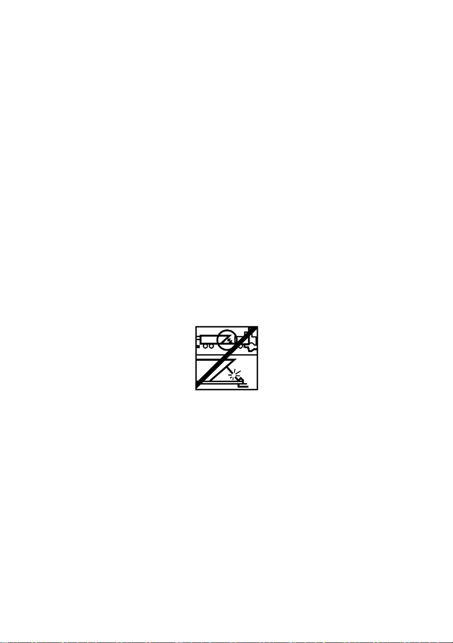
This winch is designed to move a load at ground level or up an incline.It is
neither designed nor intended for hoisting.
This winch is not to be used to lift or move people.
This winch is for intermittent use due to heat build up characteristics of
various components.If the end of the motor becomes uncomfortably hot to
touch, stop winching and allow the motor to cool down.
SAFETY PRECAUTIONS
Throughout this manual,you will find notations with the following headings:
: Indicates an imminently hazardous situation which, if not
avoided, will result in death or serious injury.
: Indicates a potentially hazardous situation which, if not
avoided, could result in death or serious injury.
: Indicates a potentially hazardous situation which, if not
avoided, may result in minor or moderate injury. This notation is also used
to alert against unsafe practices.
- 3 -
Note: Indicates additional information in the installation and
operation procedures of your winch.
Please Note: Winch is designed primarily for intermittent applications. This
winch is not designed to be used in industrial or hoisting applications.
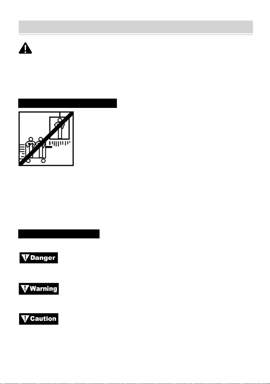
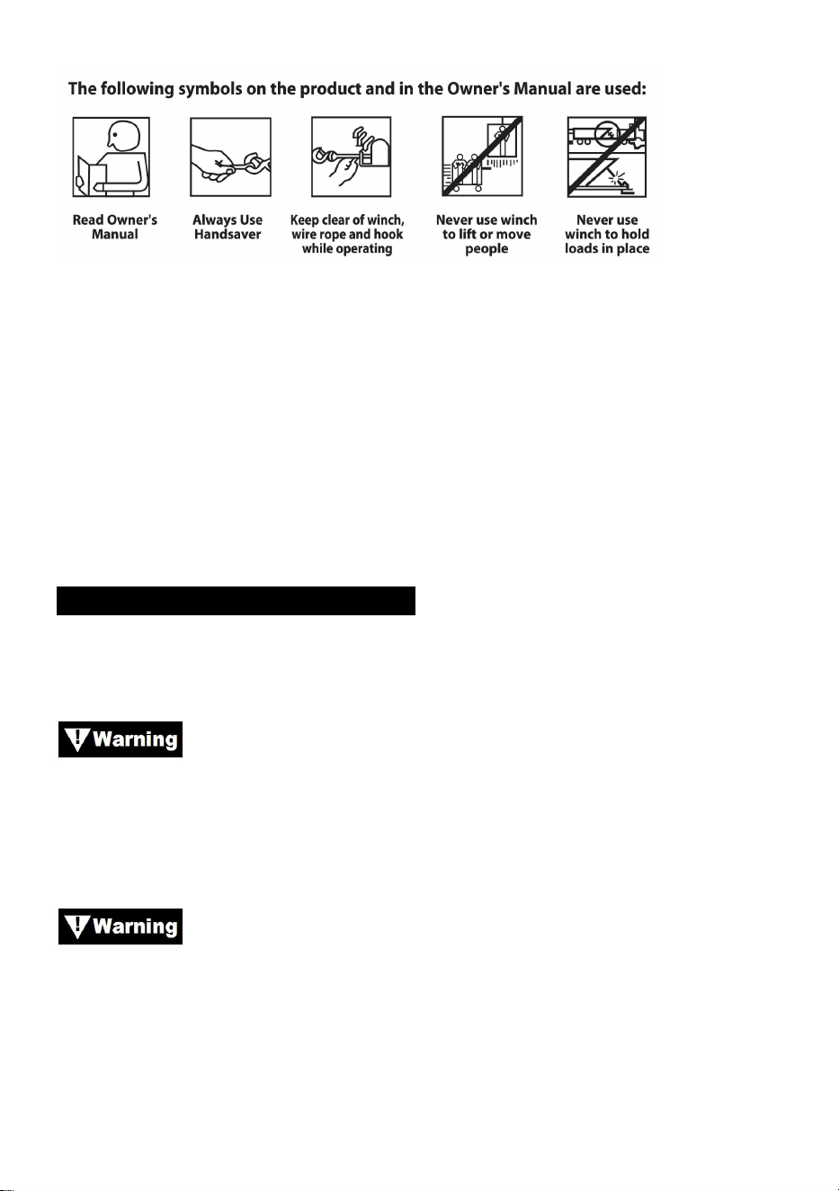
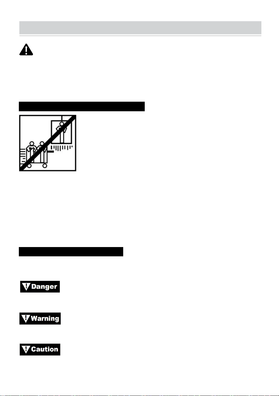
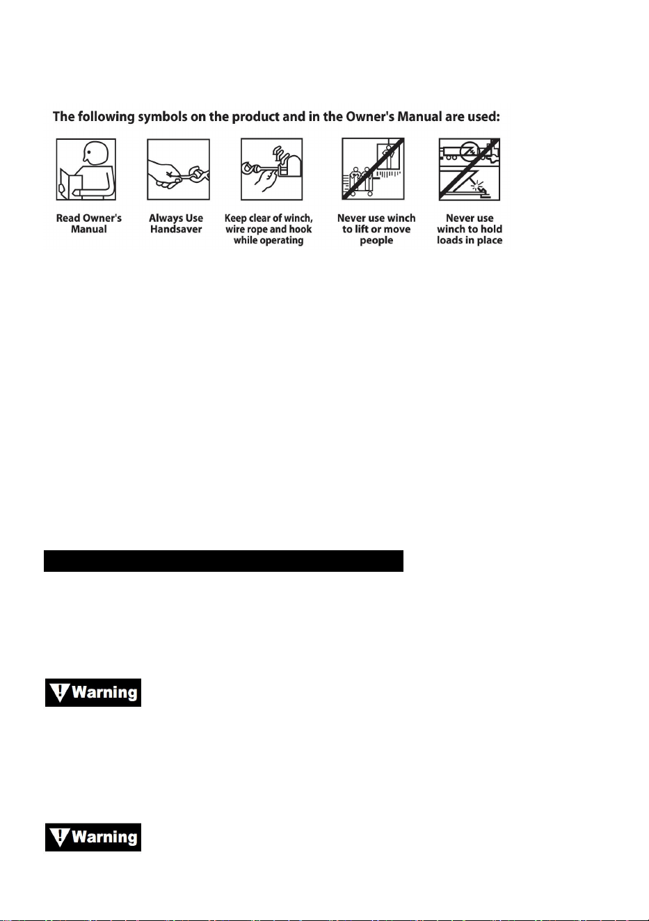
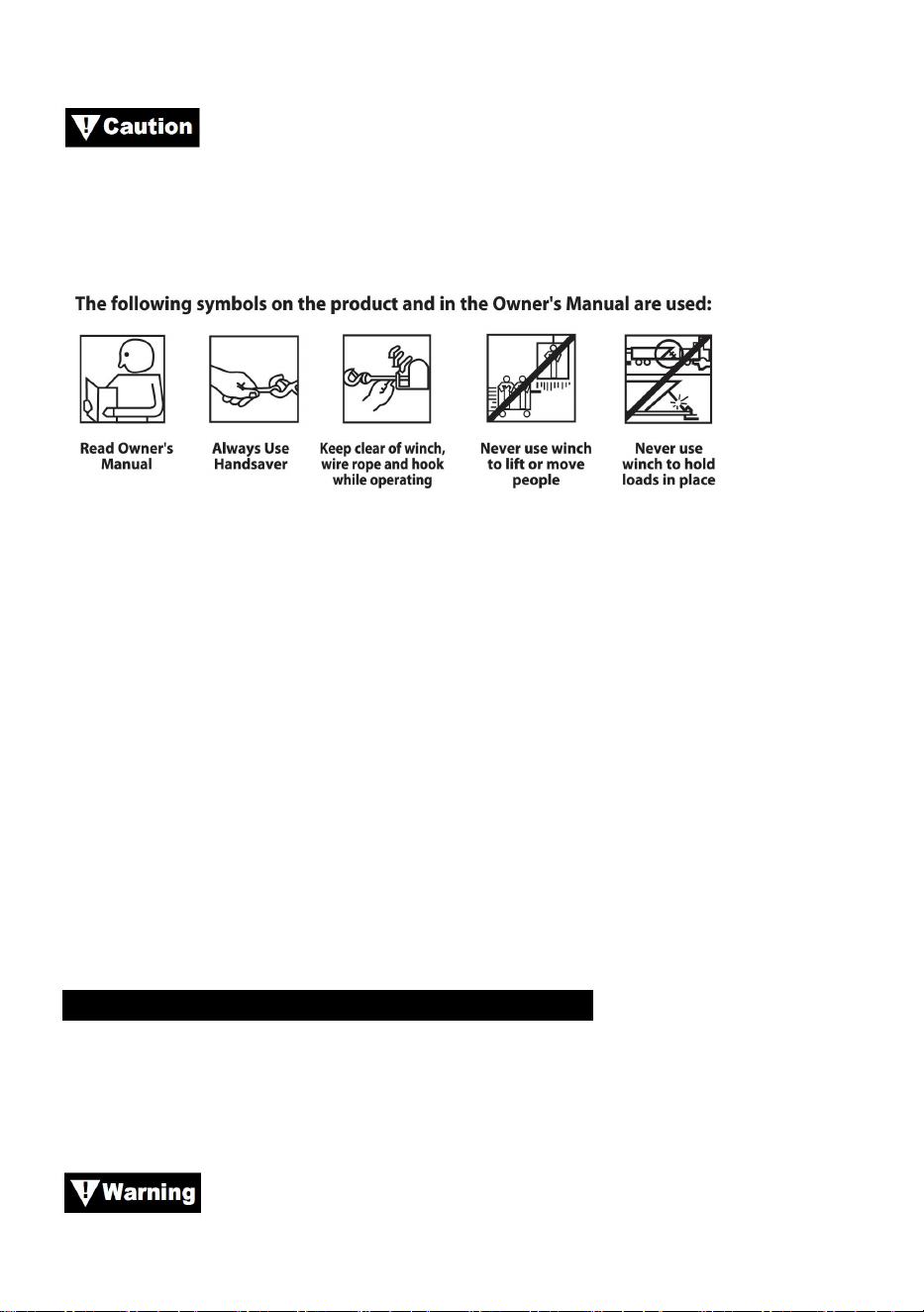
Always use handsaver on the hook.
Keep clear of winch, wire rope and hook while operating.
Never use winch to lift or move people.
Never use winch to hold loads in place.
GENERAL SAFETY INFORMATION
Your winch is a very powerful machine. If used unsafely or improperly, it
could result in property damage or personal injury.
The responsibility for safe installation and operation of the
winch and prevention of personal injury and property damage ultimately
rests with you, the operator. There is no substitute for the use of good
judgement and caution in operating a winch.
The wire rope may break before the winch stalls.
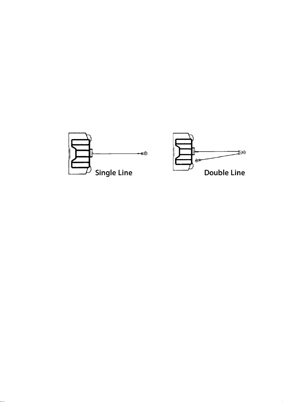
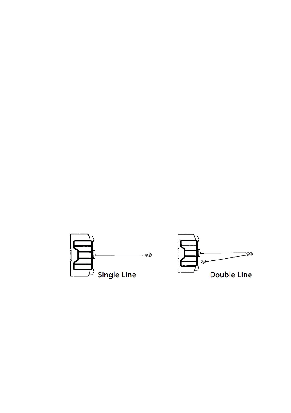
For heavy loads, use a pulley block to reduce the load on the
wire rope.
1. Maximum working load capacity is on the wire rope layer closest to the
drum. DO NOT OVERLOAD. DO NOT ATTEMPT PROLONGED
- 4 -
PULLS AT HEAVY LOADS. Overloads can damage the winch and/or
the wire rope and create unsafe operating conditions. FOR LOADS
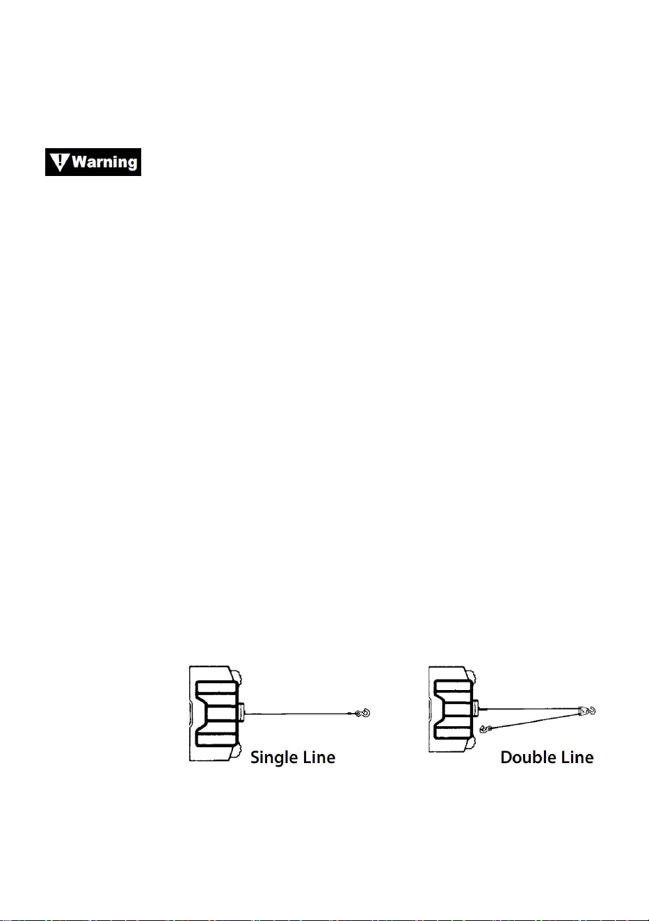
OVER 1/2 RATED CAPACITY, WE RECOMMEND THE USE OF THE
OPTIONAL PULLY BLOCK TO DOUBLE LINE THE WIRE
ROPE(Figure 1). This reduces the load on the winch and the strain on
the wire rope approximately 50%. Attach hook to load bearing part.The
vehicle engine should be running during winch operation. If
considerable winching is performed with the engine off, the battery may
be too weak to restart the engine.
Figure 1.
2. AFTER READING AND UNDERSTANDING THIS MANUAL, LEARN
TO USE YOUR WINCH. After installing the winch, practice using it so
you will be familiar with it when the need arises.
3. DO NOT “move” your vehicle to assist the winch in pulling the load.The
combination of the winch and vehicle pulling together could overload
the wire rope and the winch.
4. ALWAYS STAND CLEAR OF WIRE ROPE, HOOK AND WINCH. IN
THE UNLIKELY EVENT OF ANY COMPONENT FAILURE IT’S BEST
TO BE OUT OF HARM’S WAY.
5. Inspect wire rope and equipment frequently. A frayed wire rope with
broken strands should be replaced immediately.
6. Use heavy leather gloves when handling wire rope. Do not let wire rope
slide through your hands.
7. Never winch with less than 5 turns of wire rope around the winch drum
since the wire rope end fastener may NOT withstand full load.
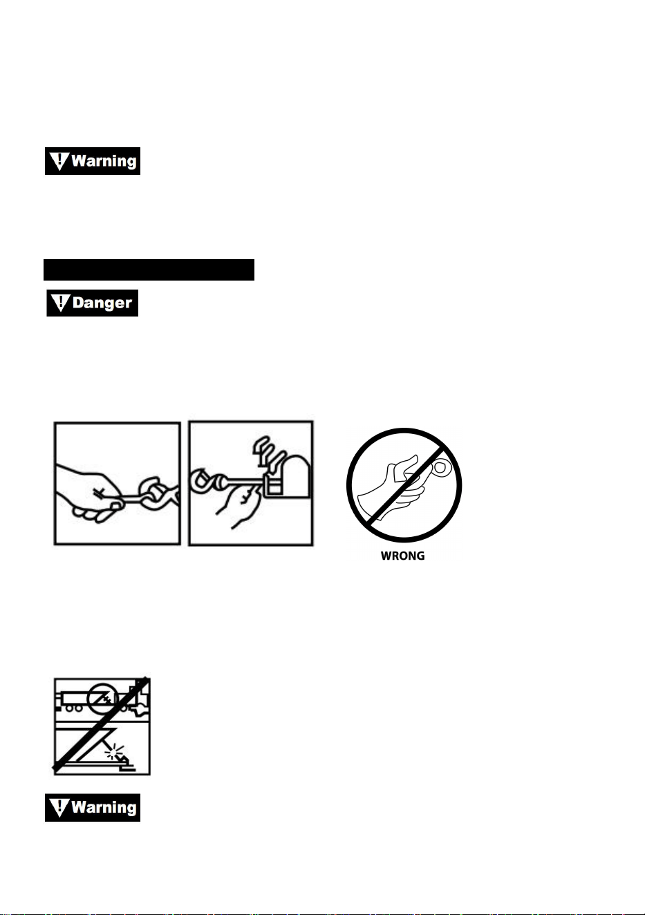
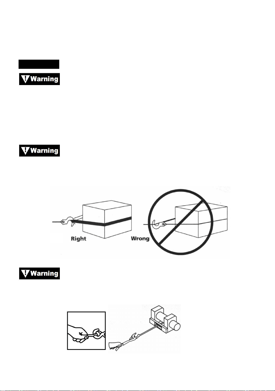
8. Never put your finger through the hook. If your finger were trapped in
the hook, you could lose your finger.
- 5 -
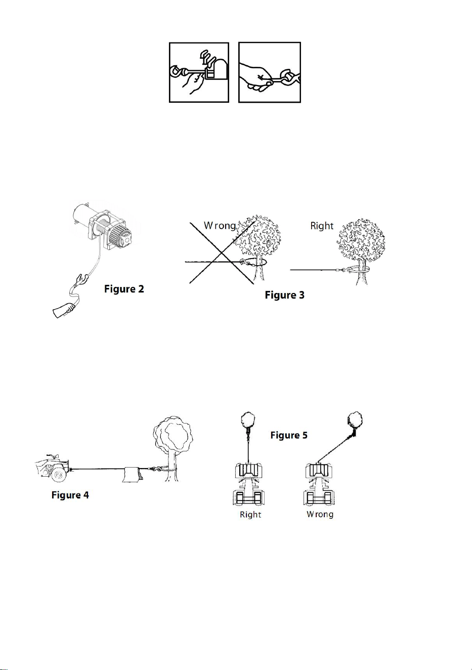
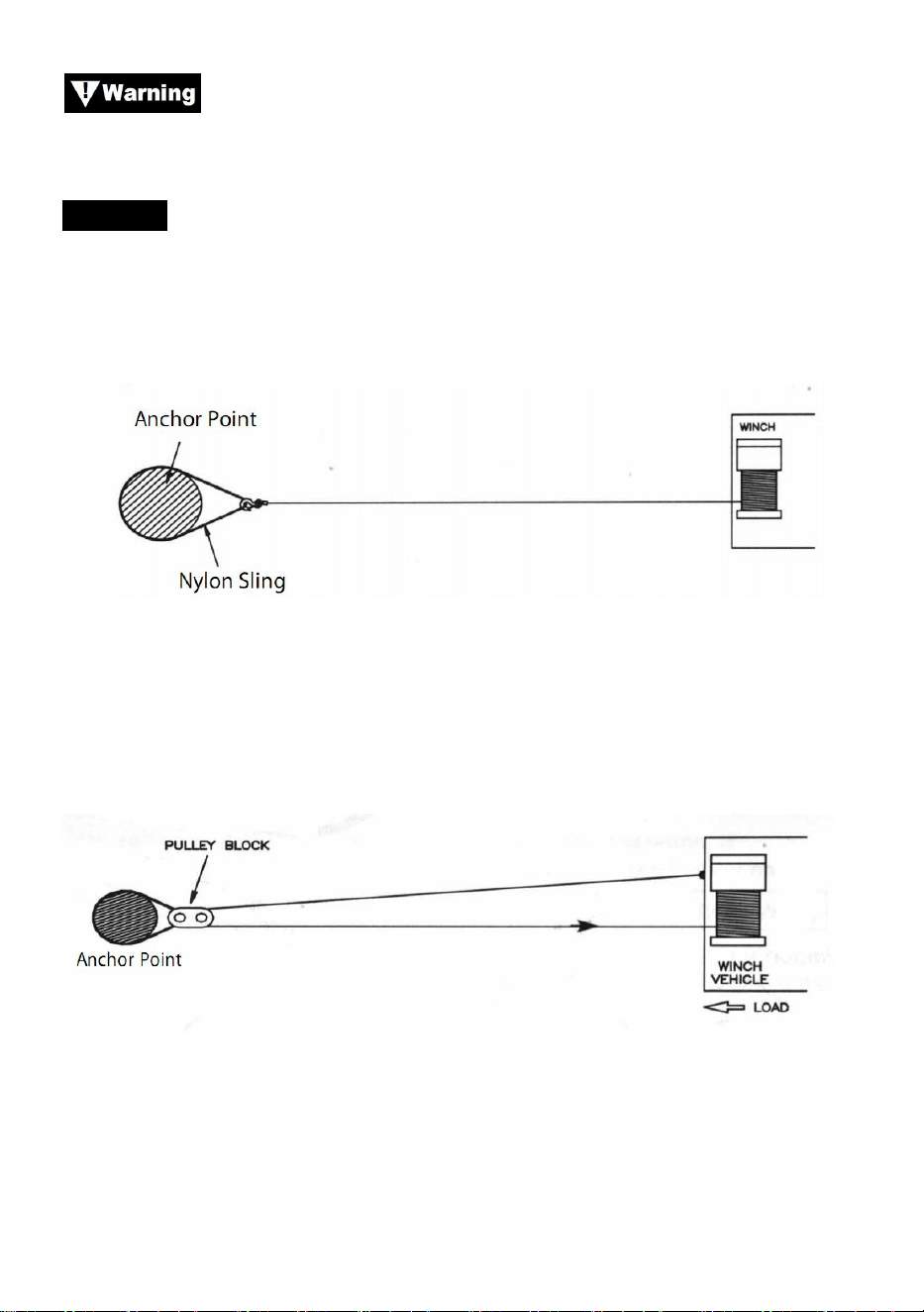
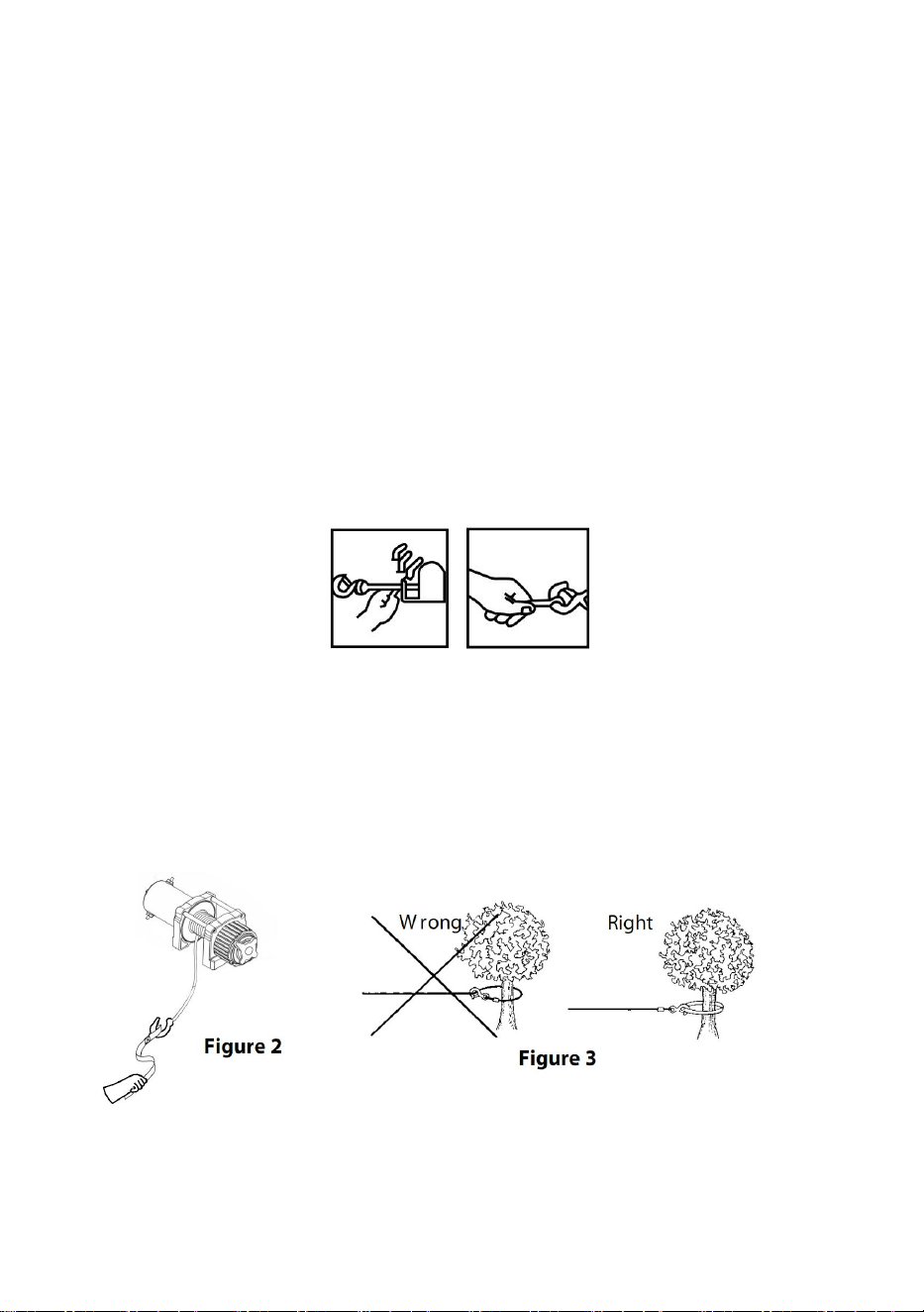
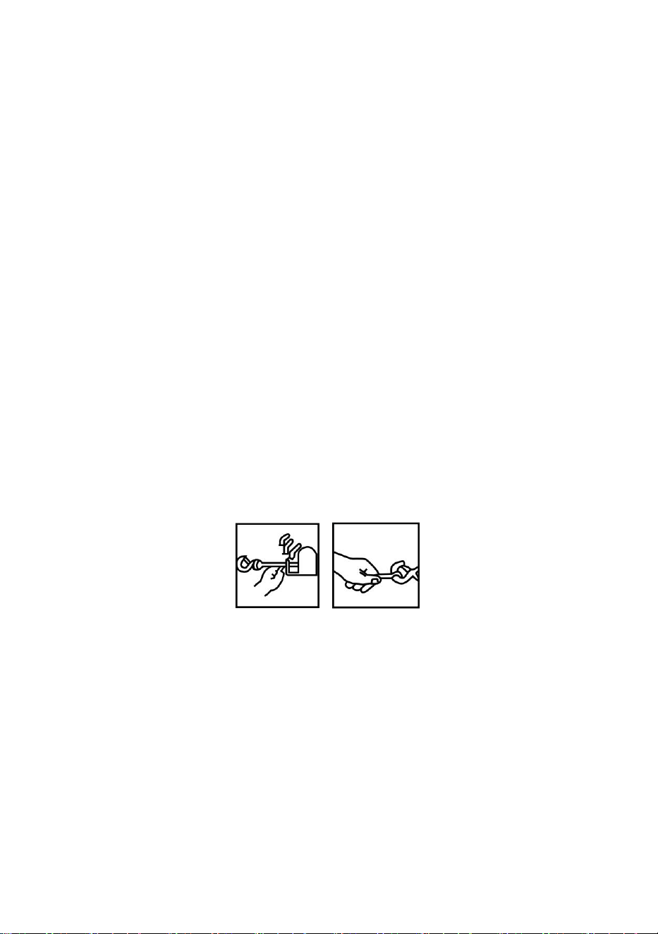
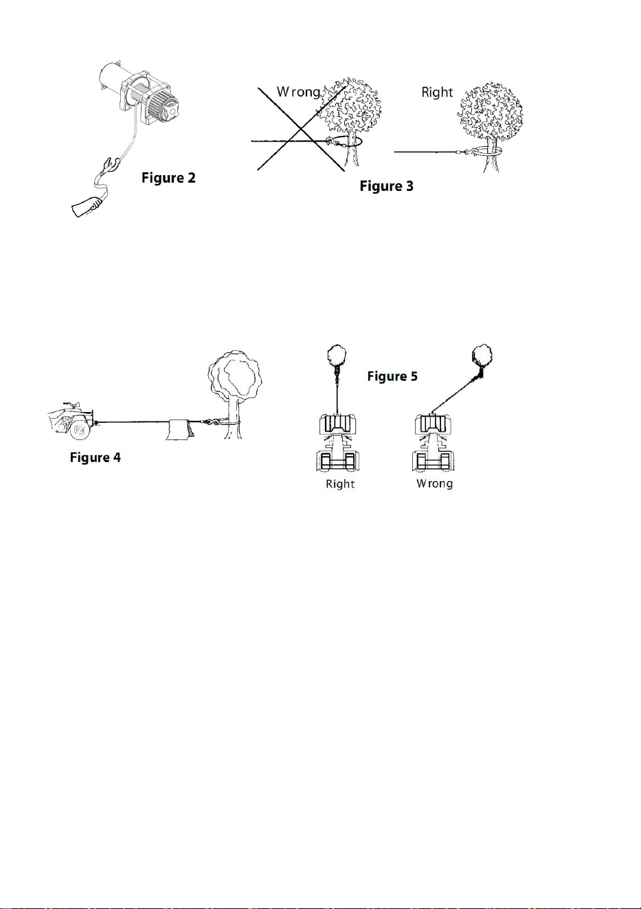
9. ALWAYS USE THE HAND SAVER When guiding the wire rope in or
out.(See Figure 2).
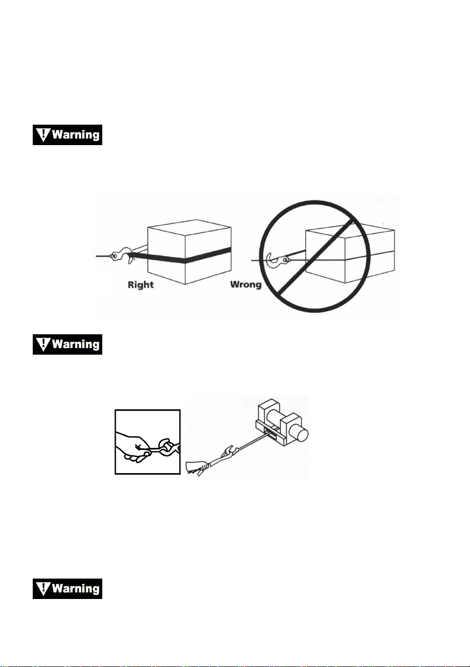
10. NEVER HOOK THE WIRE ROPE BACK ONTO ITSELF because you
could damage the wire rope. Use a nylon sling (Figure 3).
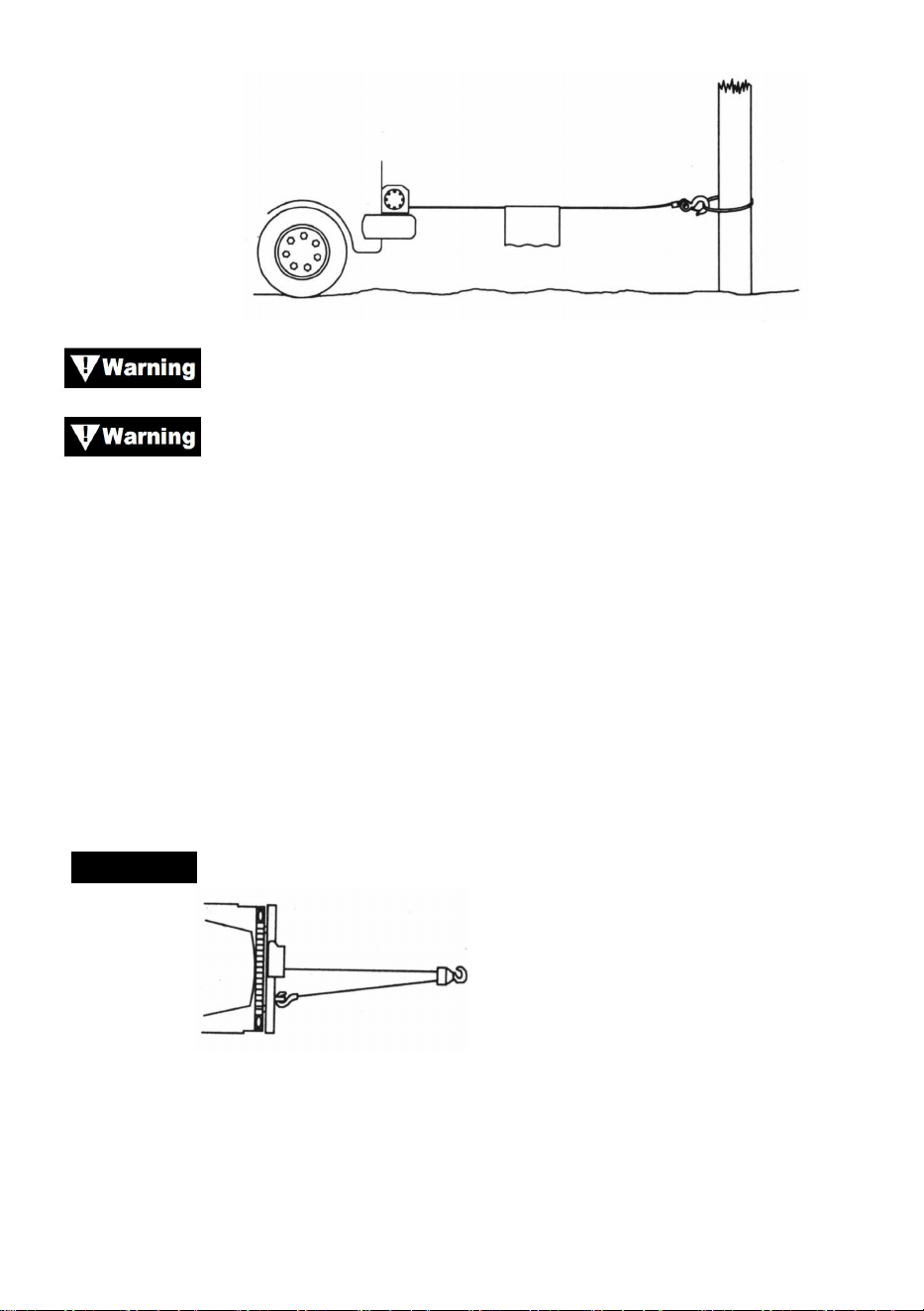
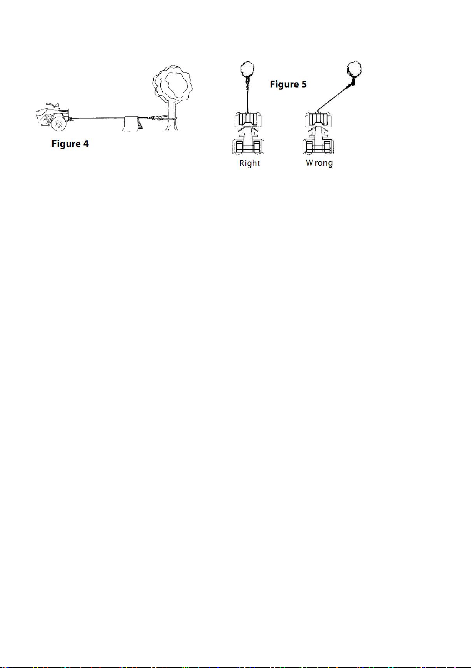
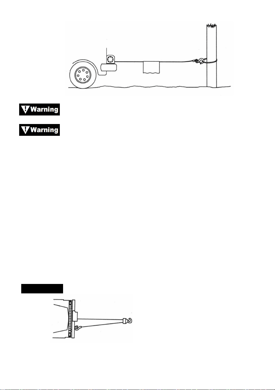
11. It’s a good idea to lay a heavy blanket or jacket over the wire rope near
the hook end when pulling heavy loads (Figure 4). If a wire rope failure
should occur, the cloth will act as a damper and help prevent the rope
from whipping.
12. AVOID CONTINUOUS PULLS FROM EXTREME ANGLES as this will
cause the wire rope to pile up on one end of the drum.This can jam the
wire rope in the winch, causing damage to the rope or the winch.
13. NEVER OBSCURE THE WARNING INSTRUCTOIN LABELS.
14. Always operate winch with an unobstructed view of the winching
- 6 -
operation.
15. Equipment such as tackle, hooks, pulley block, straps, etc. should be
sized to the winching task and should be periodically inspected for
damage that could reduce their strength.
16. NEVER RELEASE FREESPOOL CLUTCH WHEN THERE IS A LOAD
ON THE WINCH.
17. NEVER WORK ON OR AROUND THE WINCH DRUM WHEN WINCH
IS UNDER LOAD.
18. DO NOT OPERATE WINCH WHEN UNDER THE INFLUENCE OF
DRUGS, ALCOHOL OR MEDICATION.
19. ALWAYS DISCONNECT WINCH POWER LEADS TO BATTERY
BEFORE WORKING IN OR AROUND THE WINCH DRUM so that the
winch cannot be turned on accidentally.
20. When moving a load, slowly take up the wire rope slack until it
becomes taut. Stop, recheck all winching connections. Be sure the
hook is properly seated. If a nylon sling is used, check the attachment
to the load.
21. When using your winch to move a load, place the vehicle transmission
in neutral, set vehicle brake, and chock all wheels.
22. DO NOT USE THE WINCH TO HOLD LOADS IN PLACE. Use other
means of securing loads such as tie down straps.
23. USE ONLY FACTORY APPROVED SWITCHES, REMOTE
CONTROLS AND ACCESSORIES. Use of nonfactory approved
components may cause injury or property damage.
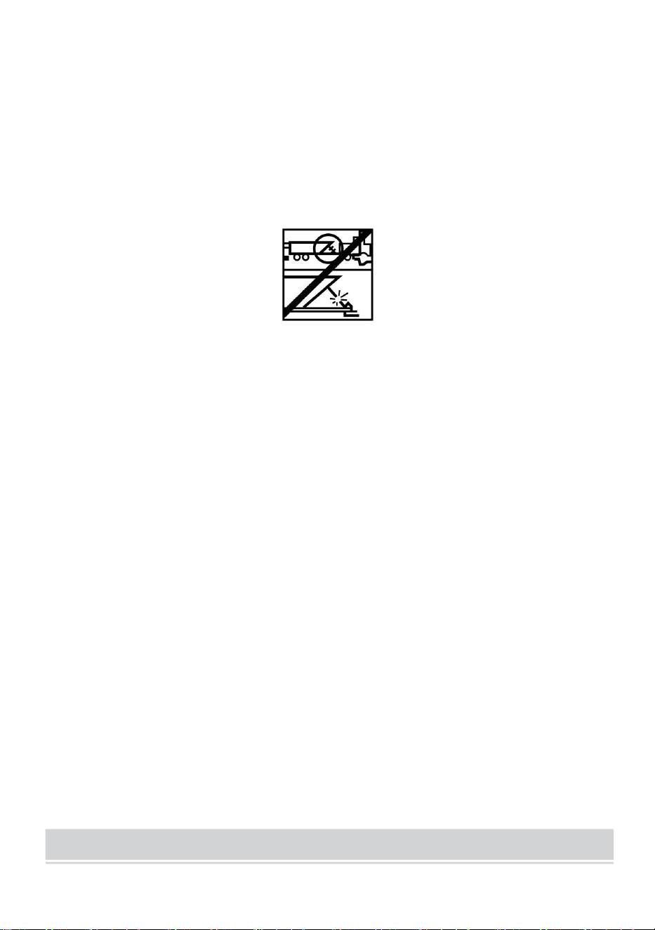
24. DO NOT MACHINE OR WELD ANY PART OF THE WINCH. Such
alterations may weaken the structural integrity of the winch.
25. DO NOT CONNECT WINCH TO EITHER 110V AC HOUSE CURRENT
OR 220V MAINS AS WINCH BURNOUT OR FATAL SHOCK MAY
OCCUR.

- 7 -
26. Never allow shock loads to be applied to winch or wire rope.
27. Use a caution when pulling or lowering a load up and down a ramp or
incline. Keep people, pets and property clear of the path of the load.
28. The switch assembly must be kept free of dirt and moisture to ensure
safe operation.
29. To prevent unauthorized use of the winch, remove pendant control and
store in a clean dry area such as the glove box.
PRODUCT SPECIFICATION
P2000-1
P3000-1C
P4000-1D
P4000-1W
Voltage
12VDC
12VDC
12VDC
12VDC
Rated power
0.95HP
1.3HP
2.2HP
2.2HP
Gear ratio
153
:
1
153
:
1
128.2
:
1
128.2
:
1
Length of
wire
1.8m
1.8m
1.8m
1.8m
Rope
Steel ,
5/32inch *
39ft
Steel ,
3/16inch *
39ft
Steel ,
1/4inch * 39ft
Synthetic ,
1/4inch * 39ft
IP
Rating
55
55
55
55
Model
SPEC.

- 8 -
Package Content
P2000-1
P3000-1C
P4000-1D
P4000-1W
Electric
Winch
1
1
1
1
Control Box
×
1
1
1
Wireless
Remote
Control
×
1
1
1
Handle
controller
1
1
1
1
Roller
Fairlead
1
1
1
1
Mounting
Bracket
1
1
1
1
Clevis Hook
1
1
1
1
Red Band
1
1
1
1
Screw Kit
1
1
1
1
Manual
1
1
1
1
Model
Parts
- 9 -
PRODUCT ASSEMBLY INSTRUCTIONS
MOUNTING YOUR WINCH
MOUNTING KITS
THE MANUFACTURE RECOMMENDS THE USE OF A MOUNT KIT FOR
SECURE MOUNTING TO YOUR VEHICLE.ATV Winch mounting kits are
normally included in the winch package. If you choose not to purchase a
mounting kit, your winch needs to be attached to a secure and flat
mounting location. Note that your winch may not be able to be operated
safely without some equipment included in the kit.
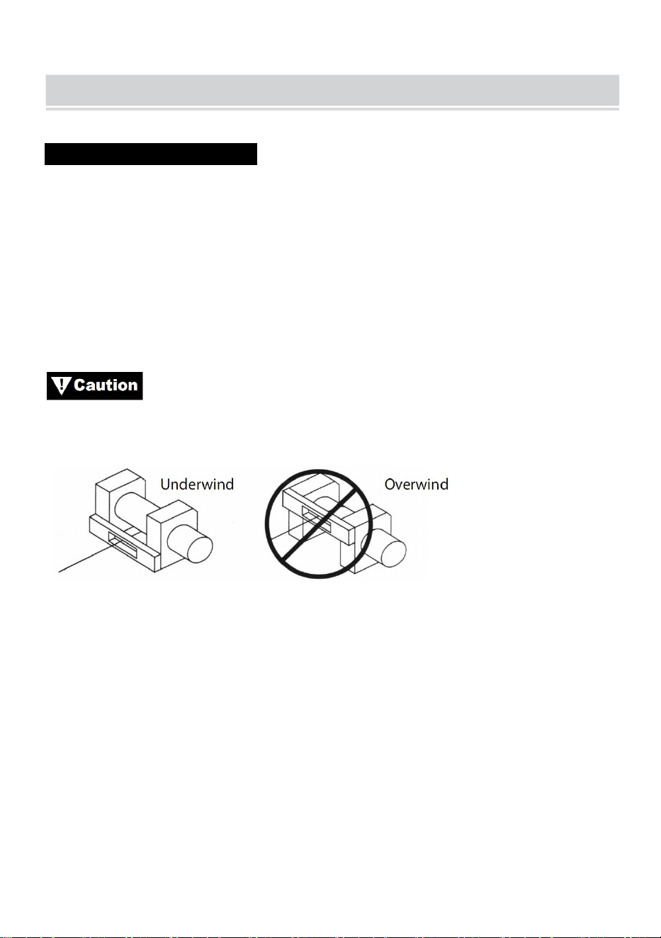
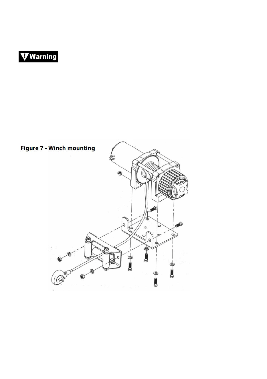
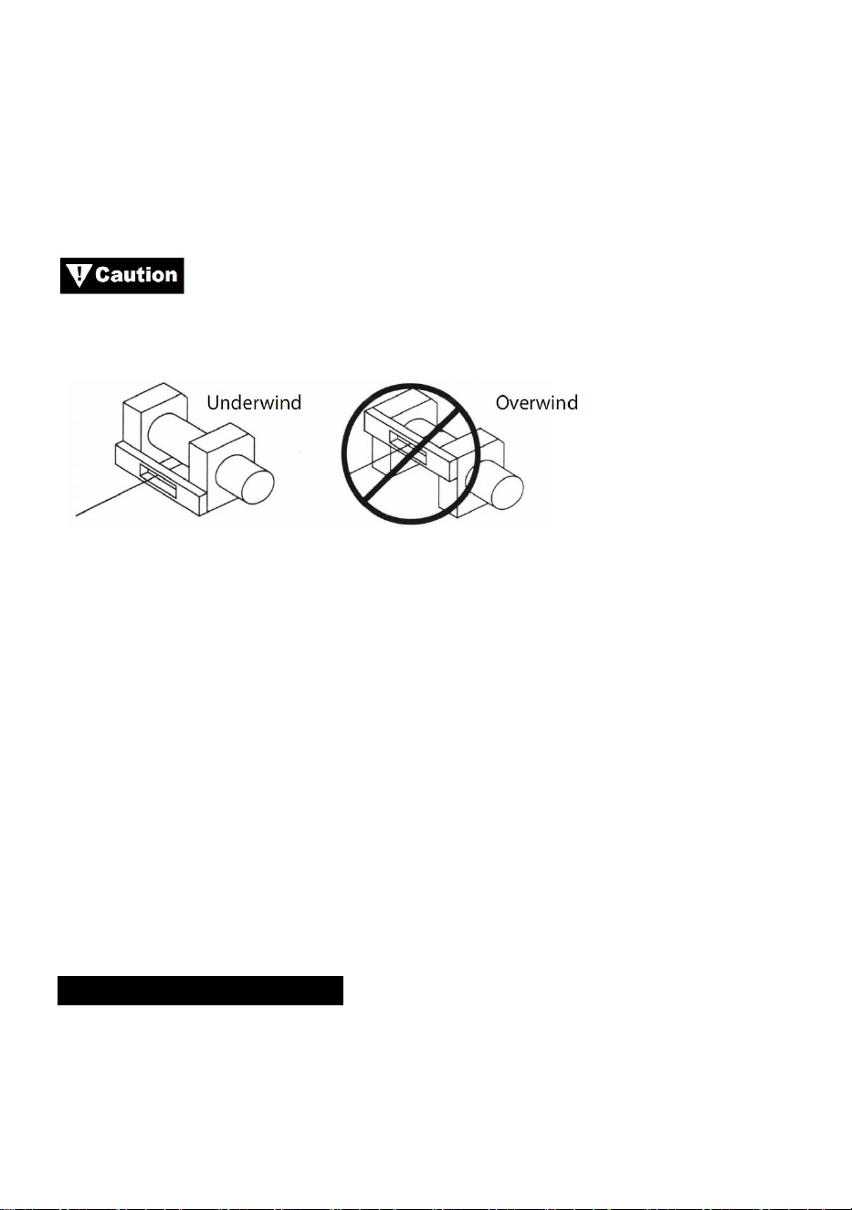
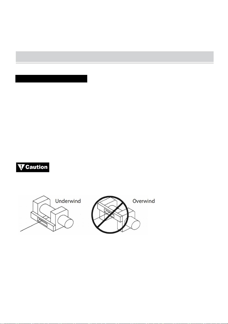
This winch must be mounted with the wire rope in the
underwound direction(Figure6).
Figure 6
Note: It is possible and not uncommon or discouraged to mount your winch
in attitudes other than those shown in this installation manual.
While mounting attitude is at your discretion, always remember that your
winch is to be operated with the wire rope in an underwound orientation on
the wire rope drum (Figure 1). Your winch is designed to ROPE IN AND
ROPE OUT in one direction. Do not attempt to reverse the operation of
your winch.

- 10 -
WINCH INSTALLATION
Note: When installing a winch, your installation may vary slightly from the
instructions and diagrams that follow, depending upon your vehicle, winch,
mounting kit or structural support.
Before you start your winch installation, disconnect the
vehicle ground and positive leads from the battery.
MINIMUM ELECTRICAL REQUIREMENTS
Be sure to select the appropriate battery or power supply to handle this
winch. If the winch is in heavy use, an auxiliary battery and heavy duty
alternator are recommended.
INSTALLATION PROCEDURE:
STEP (1)
Install mounting kit or prepare a flat, secure mounting location for winch to
make sure the motor, drum and gear box are aligned correctly. Carefully
follow the instructions included with the mounting kit.
Be sure structural support is strong enough to support rated
capacity of the winch.
Note: If you don’t have a mounting kit, you will need to drill holes in the
structural support. Be sure that your structural support is at least 3/16”
(5mm) thick.
If different length bolts, nuts, washers and other hardware
are required for your installation, always use hardware that equals or
exceeds the strength grade of the supplied hardware.
- 11 -
Step (2)
Position the winch over the holes in the mounting kit or structural support.
As you position the winch, make sure that the wire rope
winds in the proper rotation on the drum. Failure to operate the winch in the
proper direction can cause the winch brake (if equipped) to operate
improperly, and /or cause the winch to fail.
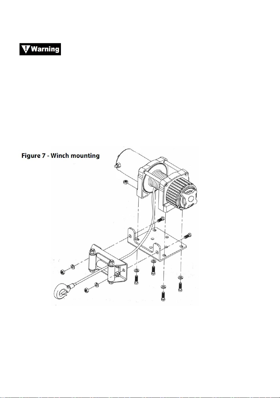
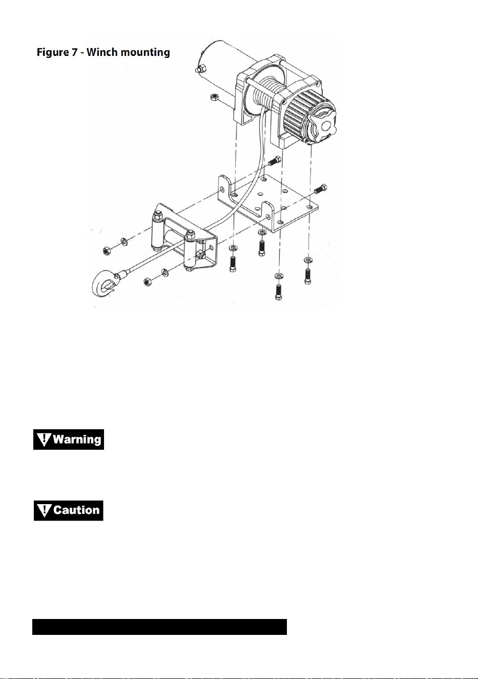
Step (3)
Secure winch (figure 7) to mounting kit or structural support using bolts,
lock washers and square nuts supplied with winch.
Step (4)
Secure roller fairlead (Figure 7) to mounting plate or structure support
using hardware supplied or by using two (2) M8x 20L 8.8 Grade Tensile
steels bolts.

- 12 -
Be sure that both the mounting plate and winch
hardware have been properly tightened.
No part of the vehicle (skidplates, wiring, auxiliary lights,
tires, etc.) should impede the operation of your winch. When mounting,
check all vehicle and winch parts for free operation. Be sure that the winch
mounting location does not significantly reduce ground clearance.
SOLENOID BOX MOUNTING
1. The solenoid box disconnects your winch from battery when the vehicle
is turned off.
2. The solenoid box should be mounted close to the battery and in a
location that is as clean and dry as possible.
3. Ensure the solenoid box location selected provides sufficient clearance
from all metal structures, such as frame tubes.
- 13 -
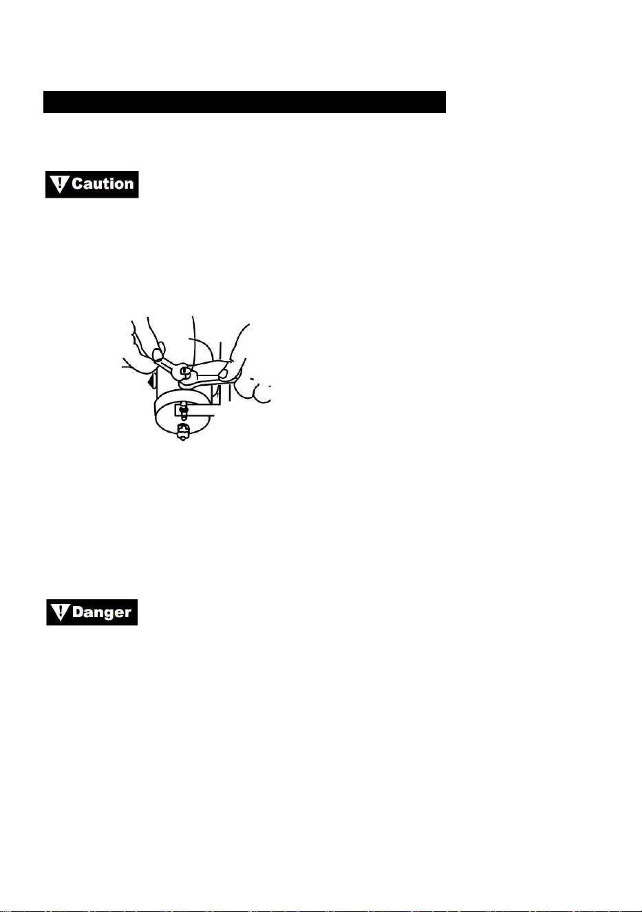
TOGGLE SWITCH INSTALLATION
APPLICATIONS: ATV SERIES
When attaching wires to the motor or slenoid terminals, hold
the inner nut with a wrench while tightening the outer nut with a second
wrench. Do not allow terminals to rotate in their housings. Rotation may
cause internal wire breakage or part misalignment (Figure9).
Figure 9—Proper Terminal Tightening
Step (1)
Check to ensure that the vehicle ground and positive leads from the battery
are disconnected before performing any electrical work.
DO NOT ATTEMPT TO INSTALL WIRING WHEN THE
BATTERY IS CONNECTED. Automotive batteries contain falmmable and
explosive gases. Wear eye protection during installation and remove all
metal jewelry. Do not lean over battery while making connections.
Step (2)
Route the wiring harness, attaching the harness to hard points on the
vehicle with cable ties.
Note: When routing the wires, the appropriate terminals should be located
near the battery, switch mounting point, and winch. Your installation
requirements will vary depending upon your vehicle and winch. Make sure
wires are long enough to reach the battery, switch mounting point and
winch.
- 14 -
Ensure that wiring harness does not interfere or come in
contact with any hot or moving engine, suspension, steering, braking or
exhaust parts.
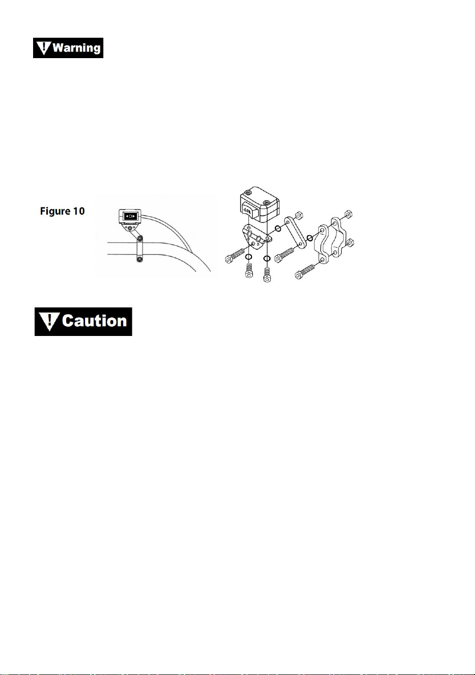
Step(3)
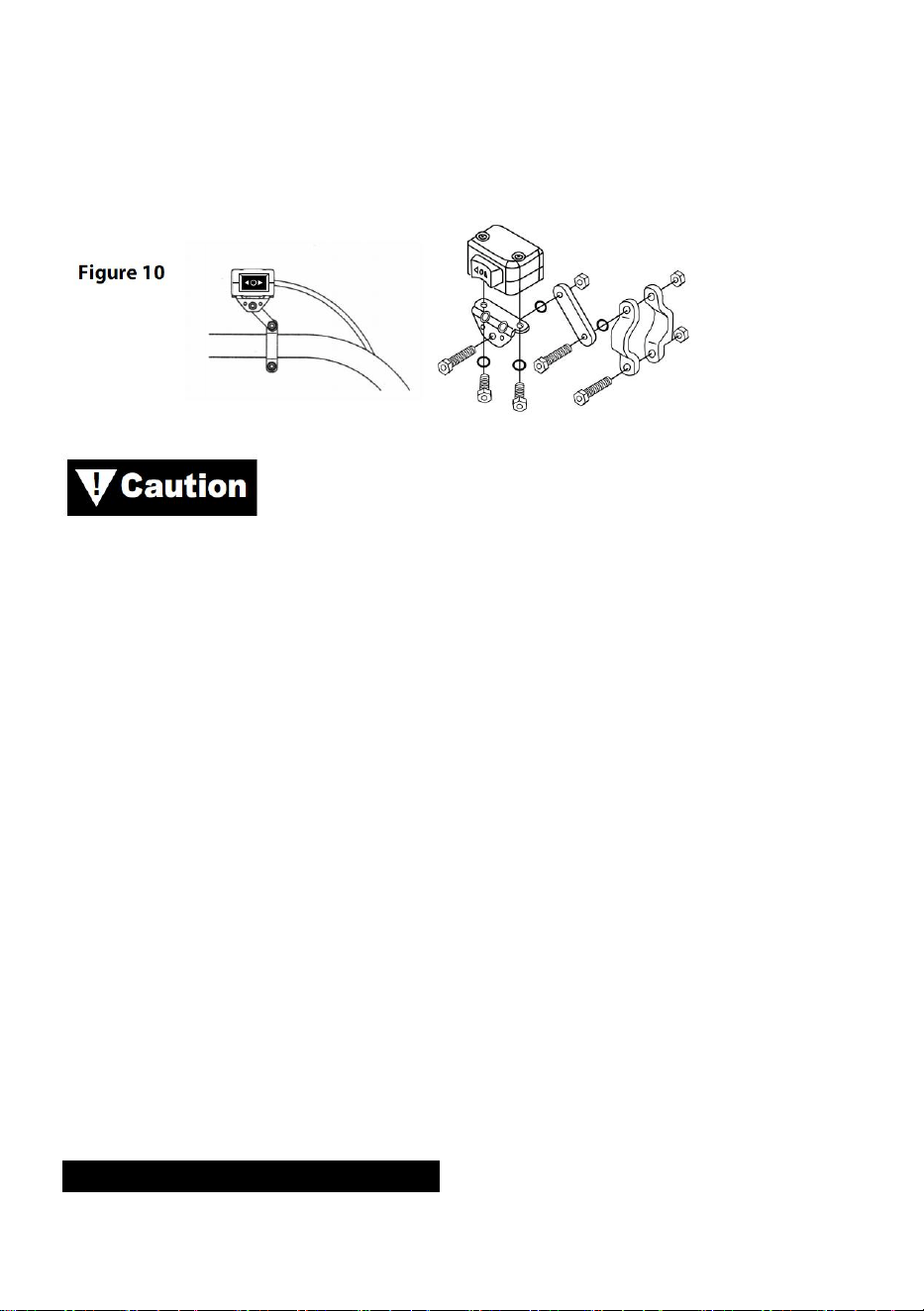
Using the supplied clamps, bracket and hardware mount toggle switch in a
convenient location. See Figure 10.
ALWAYS USE THE TOGGLE SWITCH MOUNTING
BRACKET, SCREWS, AND LOCK NUTS PROVIDED. Screw lengths are
sized for correct penetration into switch box. Excess penetration may result
in short circuits that could lead to wire over heating.
Step (4)
It is recommended that the switch be installed on the left handlebar.
- 15 -
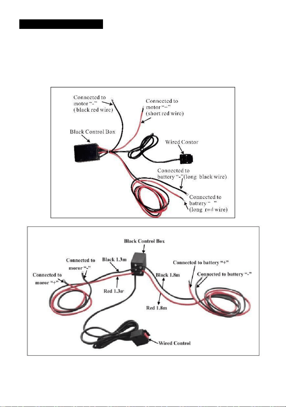
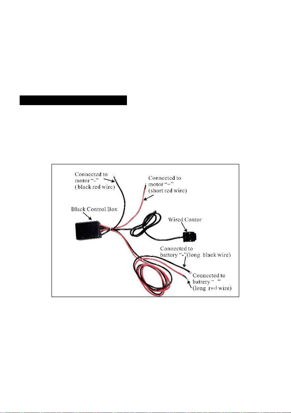
WIRING INSTALLATION
Step (1)
Route the short red and black color coded wires to the motor.
Route the long red and black color coded wires to the battery.

- 16 -
Step(2)
Check that all wiring is clear of sharp edges and pinch points.
Secure loose wiring with tie wraps or electrical tape.
Never leave the switch plugged in when winch is not in use.

- 17 -
PRODUCT INSTRUCTIONS
Before testing winch operation, be sure to reel off
approximately two feet of wire rope.
TEST DRIVE
1. Double check that all wiring is correct and that there no exposed
terminals that can short to the vehicle frame.
2. Turn the ignition key to the ON position. Check winch for proper
operatoin.
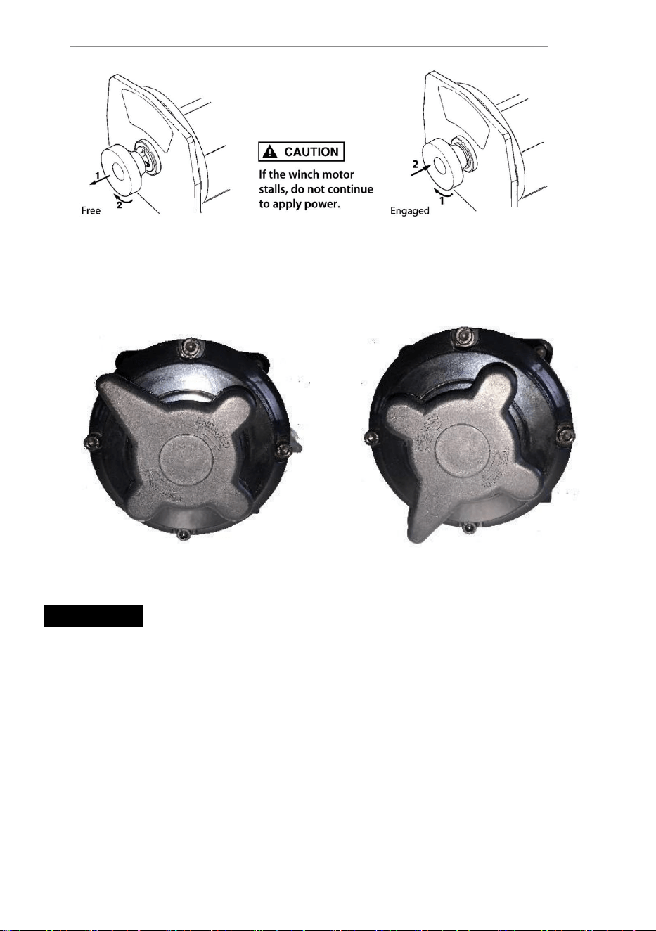
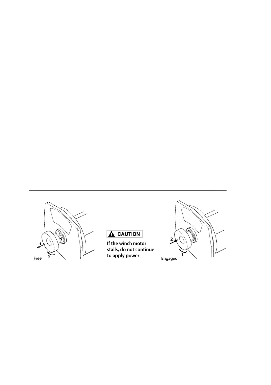
FREE SPOOL OPERATION
Pull and turn the clutch knob to the “Free ” position.If there is a load on the
wire rope, the clutch knob may not pull out easily. DO NOT FORCE THE
CLUTCH KNOB. Release tension on the clutch by jogging out some of the
wire rope. Release the clutch and pull out the wire rope and secure to
anchor or load. Check that there are at least five 5 turns of wire rope left on
the drum. Re-engage the drum by returning the clutch knob to the
“Engaged” position. Activate the winch in Cable Out momentarily to check
drum rotation direction. If the drum rotates in the wrong direction, recheck
your wiring.
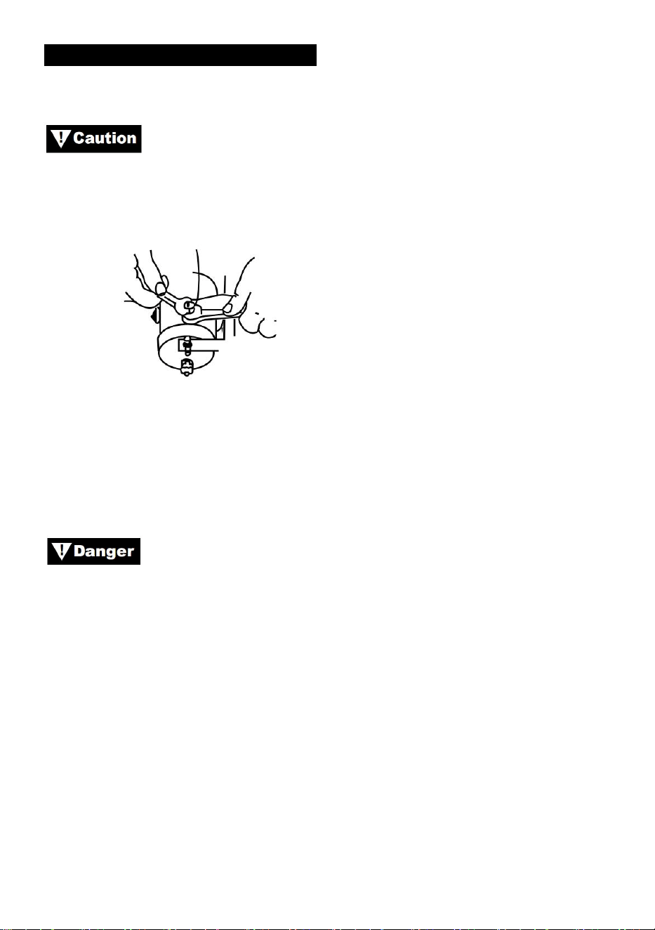
Caution:Turn the clutch knob according to the arrows and
instructions on it to engage or disengage the winch gears.
Caution: Clutch must be fully engaged before winching. Never
engage clutch knob while drum is turning.
- 18 -
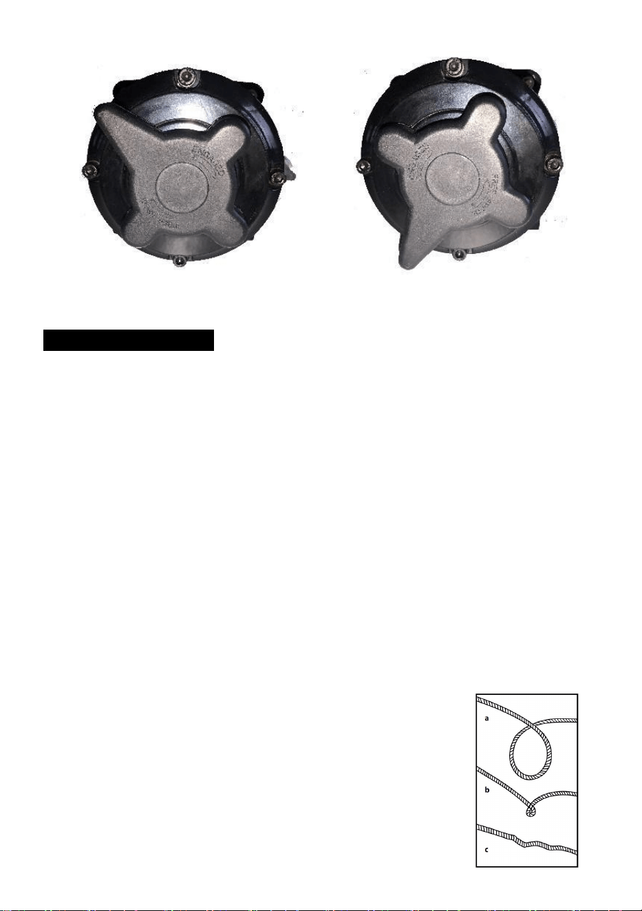
ENGAGED: FREESPOOL:
WIRE ROPE
1. The life of the wire rope is directly related to the care it receives. The
wire rope on a new winch, and any replacement ropes, should be
respooled under a minimum of 100lb load before using the winch.
Failure to do this will result in wire rope damage. Inspect wire rope
before use. Mashed, pinched, frayed or kinked areas severely reduce
the load-carrying capacity. Replace damaged wire rope.

- 19 -
2. Prevent kinks before they occur.
(a) This is the start of a kink. At this time, the wire rope should be
straightened.
(b) The wire rope was pulled and the loop has
tightened to a kink.The wire rope is now permanently
damaged and should not be used.
(c) The result of kinking is that each strand pulls
a different amount causing the strands under
greatest tension to break and reduce load
capacity of the wire rope.
3. When it is necessary to respool the wire rope under no load after use,
hold the remote switch lead in one hand and the wire rope in the other.
Start from as far from the vehicel as the remote switch will allow,
activate the switch, walk in several feet of rope and release switch.
Repeat the process. Always release the swtich before your hand
comes within four feet from the fairlead (if fitted).
4. Be sure the wire rope is distributed evenly and tightly on the drum. A
loosely wound drum allows the wire rope to work its way down into the
layers of wire rope on the drum and become wedged.
5. It is not advisable to grease or oil the wire rope due to dirt
contamination that will reduce the wire rope life.
REPLACE THE WIRE ROPE
1. If the wire rope has become worn or is beginning to show signs of
strands breaking it must be replaced before being used again. To do
this, remove the defective rope by free spooling. Remove the bolt on
the drum and release the rope.
2. Insert the end of the new rope and secure bolt tightly.
- 20 -
3. Engage the clutch and re-spool the new rope on the drum keeping
tension on the rope as it spools. Ensure that the rope is respooling in
the underwind position.
Only replace the wire rope with the identical replacement part
recommended by the manufacturer.
PREPARING THE WEINCH
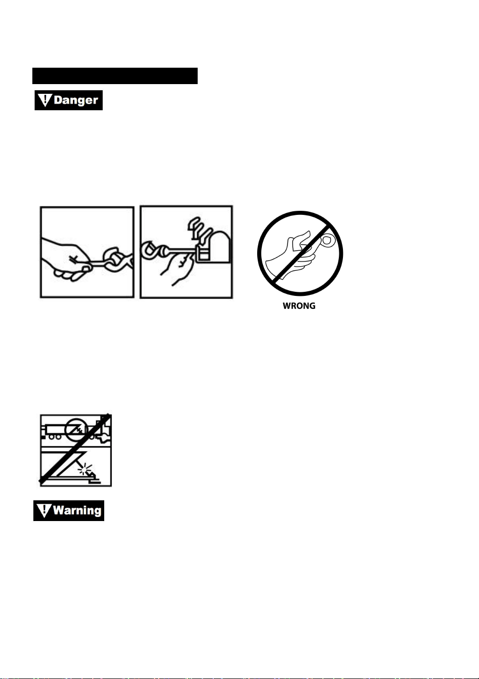
Wear heavy leather gloves when handling wire rope, even
with gloves on. When handling the hook, always use handsaver (See
Figure 12.) Never put your fingers into your hook. Placing finger(s) in hook
could result in injury.
Figure 12
1.When anchoring the pulling vehicle, set the parking brake and block or
chock the wheels. Keep the vehicle’s foot brake depressed and place
automatic and manual transmissions in neutral.
Inspect switch and wiring for cracks, pinched spots, frayed
wire, or loose connections. A damaged, shorted lead could cause the
- 21 -
winch to run as soon as it is plugged in.
1.When using the remote switch inside a vehicle, always pass it through a
window to avoid pinching the wire in the door.
WINCHING
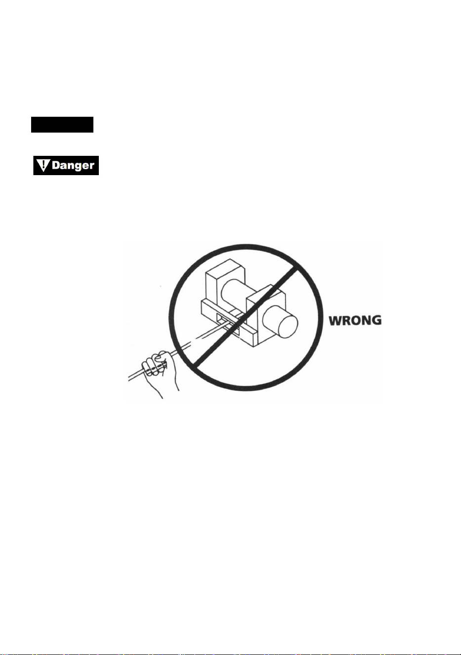
Never touch the wire rope or hook while they are in tension or
under load. Even at rest, the winch may have the wire rope in tension.
Never guide a wire rope under tention onto the drum with your hands (See
Fig. 13).
Figure 13
1. Winch with at least five wraps of wire rope around the winch drum.
With fewer wraps, the wire rope could pull loose from the drum under load.
2. When pulling a load, place a blanket, jacket or tarpaulin over the wire
rope near the hook end(see Fig 14). This will slow the snap back of a
broken wire rope and help to prevent serious injury. Raise hood to protect
windshield.
- 22 -
Figure 14
Note the winch’s rated capacity and do not exceed it.
When the load exceeds the maximum rated pull of the winch,
the external circuit breaker will automatically shut down the winch.To reset
the circuit breaker release the switch button. Note the winch will not be
able to restart normally until the motor heat built up from the excess strain
cools down.
1.Double line with a pulley block (see Fig.15) to reduce the load on the
winch, wire rope and battery. Double lining will also reduce winch line
speed. Be sure all equipment used meets the winch’s maximum line pull
rating. When double-lining, pulley blocks should be rated to a minimum of
two times the winch’s line pull rating.
WINCHING
Figure 15
1.If you install a tow hook for double lining, it should be attached to the
vehicle frame.
2.Equipping the winch with a fairlead wil reduce wear on the wire rope
during angle pulls.

- 23 -
3.Pull as straight as possible to reduce the buildup of wire rope on one end
of the drum.
4.The vehicle engine should be running during winch operation.If
considerable winching is performed with the engine off, the battery may be
too weak to restart the engine.
Use a pulley block to avoid winching at sharp angles.
Uneven layering will cause serious damage to the winch and wire rope. If
can be corrected by securing load, spooling out the wire rope and
repositioning it to the opposite end of the drum.
Do not disengage clutch under load, if your winch is
equipped with a freespool clutch, be certain that there is no tension on the
wire rope when you disengage the clutch. Before winching a load, be sure
the clutch is fully engaged.
Use the winch to move the load. Do no attempt to assist the
winch by moving the vehicle. The combination of the winch and vehicle
pulling could overload the wire rope and the load could break the winch.
Never rely on the winch to hold a load in place. None of our
winches are designed for load-holding applications and may unwind or fail
due to shock loading as the load is being transported. The load should be
secured by other means, and the winch hook detached from the load.
RIGGING
Take your time when rigging and include a reasonable factor
- 24 -
for safety. Improper rigging can result in damage to vehicle and equipment.
It can also cause injury.
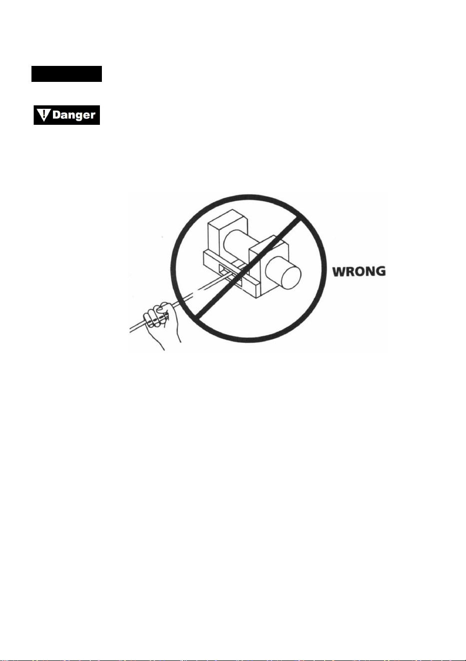
1. Never hanlde the wire rope or rigging while anyone else is at the control
switch.
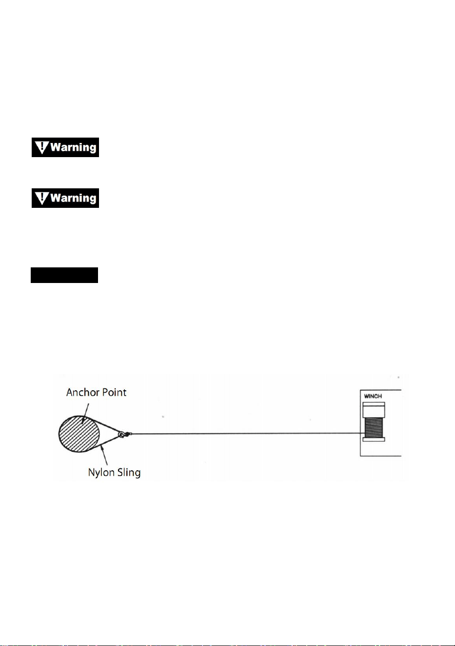
2.
Use a nylon sling when attaching the wire rope to an anchor
point. Do not attach the hook back on to the wire rope.Doing so can cause
the wire rope to break.
Figure 16
Always use the handsaver (see Fig.17). Do not hold the hook
with your hand. This is important not only when reeling wire rope in but also
when removing the wire rope from the winch under power.
Figure 17
3. Run the winch intermittently to take up wire rope slack. When using a
pulley block, be sure the wire rope is running properly in all pulleys before
applying a load.
Do not re-enage clutch while winch is running.
- 25 -
Always operate winch with an unobstructed view of the
winching operation. Never obscure warning and instruction labels.
RIGGING
3. Figure 18 illustrate the most commonly used rigging. A nylon sling is
used to protect the tree when it is used as an anchor, and the wire rope is
attached to use the sling. The use of a chain or wire rope is not
recommended due to damage it could cause to the tree.
Figure 18
4. Figure 19 illustrate a method of rigging used to obtain a mechanical
advantage. The use of a pulley block almost doubles pulling line
capacity.(Please note the pulley block is not included)
Figure 19
5. Figure 20 illustrate the use of a pulley block to change the direction of
the pull. Mechanical advantage can be obtained by attaching a pulley
block to the nylon sling with a shackle and running the wire rope to the

- 26 -
anchor point.
Figure 20
Equipment such as tackle, hooks, pulley blocks, straps, etc.
should be properly sized and rated and should be inspected periodically for
damage that could reduce their strength.
MAINTAINNENCE
1)Periodically check the tightness of mounting bolts and electrical
connections. Remove all dirt or corrosion and always keep clean.
2)Do not attemp to disassemble the gear box. Repairs should be done by
the manufacturer or an anthorized center.
3)The gear box has been lubricated using a high temperature lithium
grease and is sealed at the factory. No internal lubrication is required.

- 27 -
TROUBLE SHOOTING
Symptoms
Possible Causes
Corrective Action
Motor will not operate or
only in one direction
1.Swtich inoperative
2.Broken wires or bad
connection
3.Damaged motor
1.Replce switch
2.Check for poor connections
3.Replace or repair motor
Motor runs extremely hot
1.Long period of
opreration
2.failed or removed
overload
3.Damaged motor
1.low to cool
2.place or repair overload
3.place or repair motor
Motor runs, but with
insufficient power or line
speed
1.Weak battery
2.Battery to winch wire too
long
3.Poor battery connection
4.Poor ground
5.Damaged motor
1.Recharge or replace battery
and check charging system
2.Keep winch within distance
allowed by lead wires
3.eck battery terminals for
corrosion and clean as required
4.eck and clean connections
5.place or repair motor
Winch runs backwards
1.tor wires reversed
2.itch wires reversed
3.ttery switch installed
incorrectly
1.heck wiring
2.check wiring
3.eck battery connections
Motor runs but drum
doesn’t turn
1.Clutch not engaged
1. Engage clutch
Winch coasts
1.Excessive load
1.Reduce load or double line
Motor operations but stops
1.Excessive load/overload
1.Allow to cool

- 28 -


Technique Certificat d'assistance et de garantie électronique
www.vevor.com/support
TREUIL ÉLECTRIQUE
MODÈLE : P2000-1/P3000-1C/P4000-1D/P4000-1W
We continue to be committed to provide you tools with competitive price.
"Save Half", "Half Price" or any other similar expressions used by us only represents an
estimate of savings you might benefit from buying certain tools with us compared to the major
top brands and does not necessarily mean to cover all categories of tools offered by us. You
are kindly reminded to verify carefully when you are placing an order with us if you are
actually saving half in comparison with the top major brands.


- 1 -
MODÈLE : P2000-1/P3000-1C/P4000-1D/P4000-1W
Have product questions? Need technical support? Please feel free to
contact us:
Technical Support and E-Warranty Certificate
www.vevor.com/support
NEED HELP? CONTACT US!
This is the original instruction, please read all manual instructions
carefully before operating. VEVOR reserves a clear interpretation of our
user manual. The appearance of the product shall be subject to the
product you received. Please forgive us that we won't inform you again if
there are any technology or software updates on our product.
ELECTRIC WINCH
- 2 -
SAFE INSTRUCTIONS
AVERTISSEMENT : Lisez attentivement et comprenez toutes les
INSTRUCTIONS D'ASSEMBLAGE ET D'UTILISATION avant d'utiliser
l'appareil. Le non-respect des règles de sécurité et des autres précautions
de sécurité de base peut entraîner des blessures graves.
INFORMATIONS SUR LA DEMANDE N
Ce treuil est conçu pour déplacer une charge au niveau du sol ou sur une
pente. Il n'est ni conçu ni destiné au levage.
Ce treuil ne doit pas être utilisé pour soulever ou déplacer des personnes.
Ce treuil est destiné à une utilisation intermittente en raison des
caractéristiques d'accumulation de chaleur de divers composants. Si
l'extrémité du moteur devient inconfortablement chaude au toucher,
arrêtez le treuil et laissez le moteur refroidir.
PRÉCAUTIONS DE SÉCURITÉ
Tout au long de ce manuel, vous trouverez des notations portant les titres
suivants :
:Indique une situation dangereuse imminente qui, si elle n’est
pas évitée, entraînera la mort ou des blessures graves.
:Indique une situation potentiellement dangereuse qui, si elle
n’est pas évitée, pourrait entraîner la mort ou des blessures graves.
: Indique une situation potentiellement dangereuse qui, si elle
n'est pas évitée, peut entraîner des blessures légères ou modérées. Cette
- 3 -
notation est également utilisée pour alerter contre des pratiques
dangereuses.
Remarque : indique des informations supplémentaires dans les
procédures d'installation et d'utilisation de votre treuil.
Remarque : le treuil est conçu principalement pour des applications
intermittentes. Ce treuil n'est pas conçu pour être utilisé dans des
applications industrielles ou de levage.
Utilisez toujours un protège-main sur le crochet.
Restez à l’écart du treuil, du câble métallique et du crochet pendant le
fonctionnement.
N’utilisez jamais de treuil pour soulever ou déplacer des personnes.
N'utilisez jamais de treuil pour maintenir des charges en place.
INFORMATIONS GÉNÉRALES DE SÉCURITÉ
Votre treuil est une machine très puissante. S'il est utilisé de manière
dangereuse ou incorrecte, cela pourrait entraîner des dommages matériels
ou des blessures corporelles.
La responsabilité de l'installation et du fonctionnement
sécuritaires du treuil ainsi que de la prévention des blessures corporelles
et des dommages matériels incombe en définitive à l'opérateur. Rien ne
remplace le bon sens et la prudence dans l'utilisation d'un treuil.
Le câble métallique peut se rompre avant que le treuil ne
- 4 -
cale.
Pour les charges lourdes, utilisez un palan pour réduire la charge sur le
câble métallique.
30. La capacité de charge maximale se situe sur la couche de câble
métallique la plus proche du tambour. NE PAS SURCHARGER. NE
PAS TENTER DE TIRER DE FAÇON PROLONGÉE AVEC DE
LOURDES CHARGES. Les surcharges peuvent endommager le treuil
et/ou le câble métallique et créer des conditions de fonctionnement
dangereuses. POUR LES CHARGES SUPÉRIEURES À LA MOITIÉ
DE LA CAPACITÉ NOMINALE, NOUS RECOMMANDONS
L'UTILISATION DU BLOC DE POULIE EN OPTION POUR DOUBLE
LIGNE DU CÂBLE MÉTALLIQUE (Figure 1). Cela réduit la charge sur
le treuil et la tension sur le câble métallique d'environ 50 %. Fixez le
crochet à la pièce porteuse. Le moteur du véhicule doit tourner pendant
le fonctionnement du treuil. Si un treuillage important est effectué avec
le moteur éteint, la batterie peut être trop faible pour redémarrer le
moteur.
Figure 1.
31. APRÈS AVOIR LU ET COMPRIS CE MANUEL, APPRENEZ À
UTILISER VOTRE TREUIL. Après avoir installé le treuil,
entraînez-vous à l'utiliser afin de vous familiariser avec lui lorsque le
besoin s'en fera sentir.
32. NE « déplacez » PAS votre véhicule pour aider le treuil à tirer la charge.
La combinaison du treuil et du véhicule tirant ensemble pourrait
surcharger le câble métallique et le treuil.
33. RESTEZ TOUJOURS À L'ÉCART DU CÂBLE MÉTALLIQUE, DU
- 5 -
CROCHET ET DU TREUIL. DANS LE CAS PEU PROBABLE D'UNE
DÉFAILLANCE D'UN COMPOSANT, IL EST PRÉFÉRABLE DE SE
TENIR À L'ÉCART DU DANGER.
34. Inspectez régulièrement le câble métallique et l'équipement. Un câble
métallique effiloché avec des brins cassés doit être remplacé
immédiatement.
35. Utilisez des gants en cuir épais pour manipuler le câble métallique. Ne
laissez pas le câble métallique glisser entre vos mains.
36. Ne jamais utiliser le treuil avec moins de 5 tours de câble métallique
autour du tambour du treuil, car l'attache d'extrémité du câble
métallique peut NE PAS supporter la pleine charge.
37. Ne jamais mettre le doigt dans l'hameçon. Si votre doigt restait coincé
dans l'hameçon, vous pourriez le perdre .
38. UTILISEZ TOUJOURS LE PROTECTEUR DE MAIN lorsque vous
guidez le câble métallique vers l'intérieur ou vers l'extérieur (voir la
figure 2).
39. NE JAMAIS RETIRER LE CÂBLE SUR LUI-MÊME car vous
risqueriez de l'endommager. Utilisez une élingue en nylon (Figure 3).
40. Il est conseillé de poser une couverture ou une veste épaisse sur le
câble métallique près de l'extrémité du crochet lors de la traction de
charges lourdes (Figure 4). En cas de rupture du câble métallique, le
- 6 -
tissu agira comme un amortisseur et empêchera le câble de fouetter.
41. ÉVITEZ LES TRACTIONS CONTINUES SOUS DES ANGLES
EXTRÊMES car cela entraînerait l'accumulation du câble métallique à
une extrémité du tambour. Cela peut coincer le câble métallique dans
le treuil, provoquant des dommages au câble ou au treuil.
42. NE JAMAIS OBSCURER LES ÉTIQUETTES D'INSTRUCTIONS
D'AVERTISSEMENT.
43. Utilisez toujours le treuil avec une vue dégagée sur l’opération de
treuillage.
44. L'équipement tel que le matériel de levage, les crochets, la poulie, les
sangles, etc. doit être dimensionné en fonction de la tâche de treuillage
et doit être inspecté périodiquement pour détecter tout dommage
susceptible de réduire sa résistance.
45. NE JAMAIS LIBÉRER L'EMBRAYAGE À BOBINE LIBRE LORSQU'IL
Y A UNE CHARGE SUR LE TREUIL.
46. NE TRAVAILLEZ JAMAIS SUR OU AUTOUR DU TAMBOUR DU
TREUIL LORSQUE LE TREUIL EST SOUS CHARGE.
47. N'UTILISEZ PAS LE TREUIL SOUS L'INFLUENCE DE DROGUES,
D'ALCOOL OU DE MÉDICAMENTS.
48. DÉBRANCHEZ TOUJOURS LES CÂBLES D'ALIMENTATION DU
TREUIL À LA BATTERIE AVANT DE TRAVAILLER DANS OU AUTOUR
DU TAMBOUR DU TREUIL afin que le treuil ne puisse pas être mis en
marche accidentellement.
49. Lors du déplacement d'une charge, relâchez lentement le câble jusqu'à
ce qu'il soit tendu. Arrêtez-vous, revérifiez toutes les connexions du
treuil. Assurez-vous que le crochet est bien en place. Si une élingue en
- 7 -
nylon est utilisée, vérifiez la fixation à la charge.
50. Lorsque vous utilisez votre treuil pour déplacer une charge, placez la
transmission du véhicule au point mort, serrez le frein du véhicule et
calez toutes les roues.
51. N'UTILISEZ PAS LE TREUIL POUR MAINTENIR LES CHARGES EN
PLACE. Utilisez d'autres moyens de fixation des charges, tels que des
sangles d'arrimage.
52. UTILISEZ UNIQUEMENT DES INTERRUPTEURS, DES
TÉLÉCOMMANDES ET DES ACCESSOIRES APPROUVÉS PAR
L'USINE. L'utilisation de composants non approuvés par l'usine peut
entraîner des blessures ou des dommages matériels.
53. NE PAS USINER OU SOUDER AUCUNE PARTIE DU TREUIL. De
telles modifications peuvent affaiblir l'intégrité structurelle du treuil.
54. NE CONNECTEZ PAS LE TREUIL AU COURANT DOMESTIQUE 110
V CA OU AU SECTEUR 220 V CAR UNE BRISURE DU TREUIL OU
UN CHOC MORTEL PEUVENT SE PRODUIRE.
55. Ne laissez jamais des charges de choc être appliquées au treuil ou au
câble métallique.
56. Soyez prudent lorsque vous tirez ou abaissez une charge sur une
rampe ou une pente. Gardez les personnes, les animaux domestiques
et les biens à l'écart du trajet de la charge.
57. L'ensemble de l'interrupteur doit être maintenu exempt de saleté et
d'humidité pour garantir un fonctionnement sûr.
58. Pour éviter toute utilisation non autorisée du treuil, retirez la commande
suspendue et rangez-la dans un endroit propre et sec, comme la boîte
à gants.
PRODUCT SPECIFICATION

- 8 -
Contenu du paquet
P2000-1
P3000-1C
P4000-1D
P4000-1W
Tension
12 V CC
12 V CC
12 V CC
12 V CC
Puissance
nominale
0,95 CV
1,3 CV
2,2 CV
2,2 CV
Rapport de
démultiplicat
ion
153
:
1
153
:
1
128.2
:
1
128.2
:
1
Longueur du
fil
1,8 m
1,8 m
1,8 m
1,8 m
Corde
Acier ,
5/32 pouces *
39 pieds
Acier ,
3/16 po x 39
pi
Acier ,
1/4 pouce * 39
pieds
Synthétique ,
1/4 pouce * 39
pieds
Indice de
protection
IP
55
55
55
55
P2000-1
P3000-1C
P4000-1D
P4000-1W
Treuil
électrique
1
1
1
1
Model
SPEC.
Model
Parts

- 9 -
PRODUCT ASSEMBLY INSTRUCTIONS
MONTAGE DE VOTRE TREUIL
KITS DE MONTAGE
LE FABRICANT RECOMMANDE L'UTILISATION D'UN KIT DE
MONTAGE POUR UN MONTAGE SÉCURISÉ SUR VOTRE VÉHICULE.
Boitier de
contrôle
×
1
1
1
Télécomman
de sans fil
×
1
1
1
Contrôleur
de poignée
1
1
1
1
Guide-câble
à rouleaux
1
1
1
1
Support de
montage
1
1
1
1
Crochet à
chape
1
1
1
1
Bande rouge
1
1
1
1
Kit de vis
1
1
1
1
Manuel
1
1
1
1
- 10 -
Les kits de montage de treuil pour VTT sont normalement inclus dans
l'emballage du treuil. Si vous choisissez de ne pas acheter de kit de
montage, votre treuil doit être fixé à un emplacement de montage sûr et
plat. Notez que votre treuil peut ne pas pouvoir être utilisé en toute sécurité
sans certains équipements inclus dans le kit.
Ce treuil doit être monté avec le câble métallique dans le
sens de l'enroulement inférieur (Figure 6).
Figure 6
Remarque : Il est possible et pas rare ni déconseillé de monter votre treuil
dans des attitudes autres que celles indiquées dans ce manuel
d'installation.
Bien que l'attitude de montage soit à votre discrétion, n'oubliez jamais que
votre treuil doit être utilisé avec le câble métallique dans une orientation
sous-enroulée sur le tambour de câble métallique (Figure 1). Votre treuil
est conçu pour ENTREE ET DEROULEMENT DU CABLE dans une seule
direction. N'essayez pas d'inverser le fonctionnement de votre treuil.
INSTALLATION DU TREUIL
Remarque : lors de l'installation d'un treuil, votre installation peut varier
légèrement par rapport aux instructions et aux schémas qui suivent, en
fonction de votre véhicule, de votre treuil, de votre kit de montage ou de
votre support structurel.

- 11 -
Avant de commencer l’installation de votre treuil,
débranchez la terre du véhicule et les câbles positifs de la batterie.
EXIGENCES ÉLECTRIQUES MINIMALES
Assurez-vous de sélectionner la batterie ou l'alimentation électrique
appropriée pour faire fonctionner ce treuil. Si le treuil est utilisé de manière
intensive, une batterie auxiliaire et un alternateur robuste sont
recommandés.
PROCÉDURE D'INSTALLATION :
ÉTAPE (1)
Installez le kit de montage ou préparez un emplacement de montage plat
et sécurisé pour le treuil afin de vous assurer que le moteur, le tambour et
le boîtier d'engrenages sont correctement alignés. Suivez attentivement
les instructions fournies avec le kit de montage.
Assurez-vous que le support structurel est suffisamment
solide pour supporter la capacité nominale du treuil.
Remarque : Si vous ne disposez pas d'un kit de montage, vous devrez
percer des trous dans le support structurel. Assurez-vous que votre
support structurel a une épaisseur d'au moins 5 mm (3/16 po).
Si des boulons, écrous, rondelles et autres éléments de
différentes longueurs sont nécessaires à votre installation, utilisez toujours
du matériel dont le niveau de résistance est égal ou supérieur à celui du
matériel fourni.
Étape ( 2 )
- 12 -
Positionnez le treuil sur les trous du kit de montage ou du support
structurel.
Lors du positionnement du treuil, assurez-vous que le câble
métallique s'enroule dans le sens de rotation approprié sur le tambour. Le
fait de ne pas faire fonctionner le treuil dans le bon sens peut entraîner un
mauvais fonctionnement du frein du treuil (le cas échéant) et/ou une panne
du treuil.
Étape (3)
Fixez le treuil (figure 7) au kit de montage ou au support structurel à l'aide
de boulons, de rondelles frein et d'écrous carrés fournis avec le treuil.
Étape (4)
Fixez le guide-câble à rouleaux (figure 7) à la plaque de montage ou au
support de structure à l'aide du matériel fourni ou en utilisant deux (2)
boulons en acier à résistance à la traction M8x 20L de nuance 8,8.

- 13 -
Assurez-vous que la plaque de montage et le matériel du
treuil ont été correctement serrés.
Aucune partie du véhicule (plaques de protection, câblage,
feux auxiliaires, pneus, etc.) ne doit gêner le fonctionnement de votre treuil.
Lors du montage, vérifiez que toutes les pièces du véhicule et du treuil
fonctionnent correctement. Assurez-vous que l'emplacement de montage
du treuil ne réduit pas de manière significative la garde au sol.
MONTAGE DU BOÎTIER SOLÉNOÏDE
4. Le boîtier solénoïde déconnecte votre treuil de la batterie lorsque le
véhicule est éteint.
5. Le boîtier solénoïde doit être monté à proximité de la batterie et dans
un endroit aussi propre et sec que possible.
6. Assurez-vous que l'emplacement du boîtier solénoïde sélectionné offre
un espace suffisant par rapport à toutes les structures métalliques,
telles que les tubes du châssis.
- 14 -
INSTALLATION DE L'INTERRUPTEUR À BASCULE
APPLICATIONS : SÉRIE ATV
Lors de la fixation des fils aux bornes du moteur ou du
slenoïde, maintenez l'écrou intérieur avec une clé tout en serrant l'écrou
extérieur avec une seconde clé. Ne laissez pas les bornes tourner dans
leurs logements. La rotation peut provoquer une rupture du fil interne ou un
désalignement des pièces (Figure 9).
Figure 9 — Serrage correct des bornes
Étape (1)
Vérifiez que la terre du véhicule et les câbles positifs de la batterie sont
déconnectés avant d'effectuer tout travail électrique.
N'ESSAYEZ PAS D'INSTALLER LE CÂBLAGE LORSQUE
LA BATTERIE EST BRANCHÉE. Les batteries automobiles contiennent
des gaz inflammables et explosifs. Portez des lunettes de protection
pendant l'installation et retirez tous les bijoux métalliques. Ne vous
penchez pas au-dessus de la batterie pendant les connexions.
Étape (2)
Acheminez le faisceau de câbles en le fixant aux points durs du véhicule à
l'aide de serre-câbles.
Remarque : lors de l'acheminement des câbles, les bornes appropriées

- 15 -
doivent être situées à proximité de la batterie, du point de montage de
l'interrupteur et du treuil. Vos exigences d'installation varient en fonction de
votre véhicule et de votre treuil. Assurez-vous que les câbles sont
suffisamment longs pour atteindre la batterie, le point de montage de
l'interrupteur et le treuil.
Assurez-vous que le faisceau de câbles n'interfère pas ou
n'entre pas en contact avec des pièces chaudes ou en mouvement du
moteur, de la suspension, de la direction, du freinage ou de l'échappement.
Étape (3)
À l'aide des pinces, du support et du matériel fournis, installez l'interrupteur
à bascule dans un endroit pratique. Voir la figure 10.
UTILISEZ TOUJOURS LE SUPPORT DE MONTAGE
DE L'INTERRUPTEUR À BASCULE, LES VIS ET LES
CONTRE-ÉCROUS FOURNIS. Les longueurs de vis sont dimensionnées
pour une pénétration correcte dans le boîtier de commutation. Une
pénétration excessive peut entraîner des courts-circuits susceptibles de
provoquer une surchauffe du fil.
Étape (4)
Il est recommandé d'installer l'interrupteur sur le guidon gauche.
- 16 -
INSTALLATION DE CÂBLAGE
Étape (1)
Acheminez les fils courts de couleur rouge et noire vers le moteur.
Acheminez les longs fils de couleur rouge et noir vers la batterie.

- 17 -

- 18 -
Étape ( 2 )
Vérifiez que tout le câblage est exempt de bords tranchants et de
points de pincement.
Fixez les câbles lâches avec des attaches autobloquantes ou du
ruban isolant.
Ne laissez jamais l’interrupteur branché lorsque le treuil n’est pas
utilisé.
PRODUCT INSTRUCTIONS
Avant de tester le fonctionnement du treuil, assurez-vous de
dérouler environ deux pieds de câble métallique.
ESSAI ROUTIER
3. Vérifiez que tout le câblage est correct et qu'il n'y a pas de bornes
exposées qui pourraient provoquer un court-circuit avec le châssis du
véhicule.
4. Tournez la clé de contact sur la position ON. Vérifiez le bon
fonctionnement du treuil.
FONCTIONNEMENT DE LA BOBINE LIBRE
Tirez et tournez le bouton d'embrayage sur la position « Free ». Si le câble
- 19 -
métallique est chargé, le bouton d'embrayage peut ne pas se retirer
facilement. NE FORCEZ PAS SUR LE BOUTON D'EMBRAYAGE.
Relâchez la tension de l'embrayage en faisant sortir une partie du câble
métallique. Relâchez l'embrayage et sortez le câble métallique et fixez-le à
l'ancre ou à la charge. Vérifiez qu'il reste au moins cinq tours de câble
métallique sur le tambour. Réengagez le tambour en replaçant le bouton
d'embrayage sur la position « Engagé ». Activez momentanément le treuil
en mode Câble sorti pour vérifier le sens de rotation du tambour. Si le
tambour tourne dans le mauvais sens, revérifiez votre câblage.
Attention : tournez le bouton d'embrayage selon les flèches et les
instructions qui y figurent pour engager ou désengager les
engrenages du treuil.
Attention : l'embrayage doit être complètement engagé avant le
treuillage. Ne jamais engager le bouton d'embrayage pendant que le
tambour tourne.
ENGAGÉ: BOBINE LIBRE :
- 20 -
CÂBLE MÉTALLIQUE
6. La durée de vie du câble métallique est directement liée aux soins qu'il
reçoit. Le câble métallique d'un nouveau treuil et tout câble de
remplacement doivent être rembobinés sous une charge minimale de
100 lb avant d'utiliser le treuil. Le non-respect de cette consigne
entraînera des dommages au câble métallique. Inspectez le câble
métallique avant utilisation. Les zones écrasées, pincées, effilochées
ou pliées réduisent considérablement la capacité de charge.
Remplacez le câble métallique endommagé.
7. Prévenez les problèmes avant qu’ils ne surviennent.
(d) C'est le début d'un pli. À ce stade, le câble doit être redressé.
(e) Le câble métallique a été tiré et la boucle a
serré jusqu'à un pli. Le câble métallique est maintenant
fixé de manière permanente
endommagé et ne doit pas être utilisé.
(f) Le résultat du vrillage est que chaque brin tire
une quantité différente provoquant les brins sous
plus grande tension pour rompre et réduire la charge

- 21 -
capacité du câble métallique.
8. Lorsqu'il est nécessaire de réenrouler le câble métallique sans charge
après utilisation, tenez le câble de l'interrupteur à distance dans une
main et le câble métallique dans l'autre. Commencez aussi loin que
l'interrupteur à distance le permet du véhicule, activez l'interrupteur,
avancez sur plusieurs mètres de câble et relâchez l'interrupteur.
Répétez le processus. Relâchez toujours l'interrupteur avant que votre
main ne se trouve à moins de quatre pieds du guide-câble (si installé).
9. Assurez-vous que le câble métallique est réparti uniformément et
fermement sur le tambour. Un tambour mal enroulé permet au câble
métallique de s'enfoncer dans les couches de câble métallique du
tambour et de se coincer.
10. Il est déconseillé de graisser ou d'huiler le câble métallique en raison
de la contamination par la saleté qui réduirait sa durée de vie.
REMPLACER LE CÂBLE MÉTALLIQUE
6. Si le câble métallique est usé ou commence à montrer des signes de
rupture de brins, il doit être remplacé avant d'être réutilisé. Pour cela,
retirez le câble défectueux en le faisant tourner librement. Retirez le
boulon du tambour et libérez le câble.
7. Insérez l’extrémité de la nouvelle corde et fixez fermement le boulon.
8. Engagez l'embrayage et réenroulez le nouveau câble sur le tambour
en maintenant la tension sur le câble pendant qu'il s'enroule.
Assurez-vous que le câble s'enroule en position sous-enroulement.
Remplacez le câble métallique uniquement par la même
pièce de rechange recommandée par le fabricant.
- 22 -
PRÉPARATION DU WEINCH
Portez des gants en cuir épais lorsque vous manipulez un
câble métallique, même si vous portez des gants. Lorsque vous manipulez
le crochet, utilisez toujours un protège-mains (voir la figure 12). Ne mettez
jamais vos doigts dans le crochet. Le fait de placer vos doigts dans le
crochet pourrait entraîner des blessures.
Figure 12
1. Lors de l'arrimage du véhicule tracteur, serrez le frein de stationnement
et bloquez ou calez les roues. Maintenez la pédale de frein du véhicule
enfoncée et placez les transmissions automatique et manuelle au point
mort.
Inspectez l'interrupteur et le câblage pour déceler les fissures,
les points pincés, les fils effilochés ou les connexions desserrées. Un câble
endommagé ou court-circuité peut provoquer le démarrage du treuil dès
qu'il est branché.
1. Lorsque vous utilisez l'interrupteur à distance à l'intérieur d'un véhicule,
faites-le toujours passer par une fenêtre pour éviter de pincer le fil dans la
- 23 -
porte.
TREUILAGE
Ne jamais toucher le câble ou le crochet lorsqu'ils sont sous
tension ou sous charge. Même au repos, le treuil peut avoir le câble sous
tension. Ne jamais guider un câble sous tension sur le tambour avec les
mains (voir fig. 13).
Figure 13
1. Treuil avec au moins cinq tours de câble autour du tambour du treuil.
Avec moins de tours, le câble pourrait se détacher du tambour sous l'effet
de la charge.
2. Lorsque vous tirez une charge, placez une couverture, une veste ou une
bâche sur le câble métallique près de l'extrémité du crochet (voir la figure
14). Cela ralentira la reprise d'un câble métallique cassé et aidera à
prévenir les blessures graves. Soulevez le capot pour protéger le
pare-brise.
- 24 -
Figure 14
Notez la capacité nominale du treuil et ne la dépassez pas.
Lorsque la charge dépasse la force de traction nominale
maximale du treuil, le disjoncteur externe arrête automatiquement le treuil.
Pour réinitialiser le disjoncteur, relâchez le bouton de l'interrupteur. Notez
que le treuil ne pourra pas redémarrer normalement tant que la chaleur du
moteur accumulée à cause de la contrainte excessive ne se sera pas
refroidie.
1. Doublez le câble avec un palan (voir Fig. 15) pour réduire la charge sur
le treuil, le câble métallique et la batterie. Le doublement du câble réduira
également la vitesse du câble du treuil. Assurez-vous que tout
l'équipement utilisé répond à la capacité de traction maximale du câble du
treuil. Lors du doublement du câble, les palans doivent être conçus pour
une capacité de traction au moins deux fois supérieure à celle du câble du
treuil.
TREUILAGE
Figure 15
1. Si vous installez un crochet de remorquage pour double revêtement, il

- 25 -
doit être fixé au châssis du véhicule.
2. Équiper le treuil d'un guide-câble réduira l'usure du câble métallique lors
des tirages en angle.
3. Tirez aussi droit que possible pour réduire l’accumulation de câble
métallique à une extrémité du tambour.
4. Le moteur du véhicule doit tourner pendant le fonctionnement du treuil.
Si un treuillage important est effectué avec le moteur éteint, la batterie peut
être trop faible pour redémarrer le moteur.
Utilisez un palan pour éviter de treuiller à des angles aigus.
Une superposition inégale peut endommager gravement le treuil et le
câble métallique. Cela peut être corrigé en sécurisant la charge, en
enroulant le câble métallique et en le repositionnant à l'extrémité opposée
du tambour.
Ne désengagez pas l'embrayage sous charge. Si votre treuil
est équipé d'un embrayage à roue libre, assurez-vous qu'il n'y a aucune
tension sur le câble métallique lorsque vous désengagez l'embrayage.
Avant de treuiller une charge, assurez-vous que l'embrayage est
complètement engagé.
Utilisez le treuil pour déplacer la charge. N'essayez pas
d'aider le treuil en déplaçant le véhicule. La combinaison du treuil et de la
traction du véhicule pourrait surcharger le câble métallique et la charge
pourrait casser le treuil.
Ne comptez jamais sur le treuil pour maintenir une charge en
place. Aucun de nos treuils n'est conçu pour des applications de maintien
- 26 -
de charge et peut se dérouler ou tomber en panne en raison d'une charge
de choc pendant le transport de la charge. La charge doit être fixée par
d'autres moyens et le crochet du treuil détaché de la charge.
GRÉEMENT
Prenez votre temps lors du montage et incluez un facteur
raisonnable de sécurité. Un montage incorrect peut endommager le
véhicule et l'équipement. Il peut également causer des blessures.
4. Ne manipulez jamais le câble métallique ou le gréement pendant que
quelqu'un d'autre se trouve à l'interrupteur de commande.
5.
Utilisez une élingue en nylon pour fixer le câble métallique à
un point d'ancrage. Ne fixez pas le crochet sur le câble métallique. Cela
pourrait provoquer la rupture du câble métallique.
Figure 16
Utilisez toujours le protège-main (voir fig. 17). Ne tenez pas le
crochet avec la main. Ceci est important non seulement lors de
l'enroulement du câble métallique, mais également lors du retrait du câble
métallique du treuil sous tension.
Figure 17
- 27 -
6. Faites fonctionner le treuil par intermittence pour rattraper le mou du
câble métallique. Lorsque vous utilisez un palan, assurez-vous que le
câble métallique tourne correctement dans toutes les poulies avant
d'appliquer une charge.
Ne réenclenchez pas l’embrayage lorsque le treuil est en
marche.
Utilisez toujours le treuil en ayant une vue dégagée sur
l'opération de treuillage. Ne masquez jamais les étiquettes d'avertissement
et d'instructions.
GRÉEMENT
3. La figure 18 illustre le gréement le plus couramment utilisé. Une élingue
en nylon est utilisée pour protéger l'arbre lorsqu'il est utilisé comme
ancrage, et le câble métallique est attaché pour utiliser l'élingue.
L'utilisation d'une chaîne ou d'un câble métallique n'est pas recommandée
en raison des dommages qu'elle pourrait causer à l'arbre.
Figure 18
9. La figure 19 illustre une méthode de montage utilisée pour obtenir un
avantage mécanique. L'utilisation d'un bloc de poulie double presque la
capacité de traction de la ligne. (Veuillez noter que le bloc de poulie
n'est pas inclus)

- 28 -
Figure 19
10. La figure 20 illustre l'utilisation d'un palan pour changer la direction de
la traction. Un avantage mécanique peut être obtenu en attachant un
palan à l'élingue en nylon avec une manille et en faisant passer le
câble métallique jusqu'au point d'ancrage.
Figure 20
Les équipements tels que les palans, les crochets, les poulies,
les sangles, etc. doivent être correctement dimensionnés et évalués et
doivent être inspectés périodiquement pour détecter tout dommage
susceptible de réduire leur résistance.

- 29 -
MAINTAINNENCE
1) Vérifiez régulièrement le serrage des boulons de fixation et des
connexions électriques. Éliminez toute saleté ou corrosion et gardez
toujours l'appareil propre.
2) N'essayez pas de démonter la boîte de vitesses. Les réparations
doivent être effectuées par le fabricant ou un centre agréé.
3) La boîte de vitesses a été lubrifiée à l'aide d'une graisse au lithium haute
température et est scellée en usine. Aucune lubrification interne n'est
requise.
TROUBLE SHOOTING
Symptômes
Causes possibles
Mesures correctives
Le moteur ne fonctionne
pas ou seulement dans un
sens
1.Interrupteur inopérant
2. Fils cassés ou
mauvaise connexion
3. Moteur endommagé
1. Remplacer l'interrupteur
2. Vérifiez les mauvaises
connexions
3. Remplacer ou réparer le
moteur
Le moteur chauffe
énormément
1. Longue période de
fonctionnement
2. échoué ou supprimé
surcharge
3. Moteur endommagé
1.bas pour refroidir
2. placer ou réparer la
surcharge
3.placer ou réparer le moteur

- 30 -
Le moteur tourne, mais
avec une puissance ou
une vitesse de ligne
insuffisante
1. Batterie faible
2. Le câble de la batterie
au treuil est trop long
3. Mauvaise connexion de
la batterie
4. Terrain pauvre
5. Moteur endommagé
1. Rechargez ou remplacez la
batterie et vérifiez le système de
charge
2. Gardez le treuil à la distance
autorisée par les câbles
conducteurs
3. Vérifiez que les bornes de la
batterie ne présentent pas de
corrosion et nettoyez-les si
nécessaire.
4. Vérifiez et nettoyez les
connexions
5.placer ou réparer le moteur
Le treuil tourne à l'envers
1. fils tor inversés
2. fils de démangeaisons
inversés
3. Interrupteur de batterie
mal installé
1. Vérifiez le câblage
2. vérifier le câblage
3. Vérifiez les connexions de la
batterie
Le moteur tourne mais le
tambour ne tourne pas
1. Embrayage non
engagé
1. Enclenchez l'embrayage
Treuil côtes
1. Charge excessive
1. Réduisez la charge ou
doublez la ligne
Fonctionnement du
moteur mais arrêts
1. Charge
excessive/surcharge
1.Laisser refroidir

- 31 -


Technisch Support und E-Garantie-Zertifikat www.vevor.com/support
ELEKTRISCHE WINDE
MODELL: P2000-1/P3000-1C/P4000-1D/P4000-1W
We continue to be committed to provide you tools with competitive price.
"Save Half", "Half Price" or any other similar expressions used by us only represents an
estimate of savings you might benefit from buying certain tools with us compared to the major
top brands and does not necessarily mean to cover all categories of tools offered by us. You
are kindly reminded to verify carefully when you are placing an order with us if you are
actually saving half in comparison with the top major brands.

- 1 -
MODELL: P2000-1/P3000-1C/P4000-1D/P4000-1W
Have product questions? Need technical support? Please feel free to
contact us:
Technical Support and E-Warranty Certificate
www.vevor.com/support
NEED HELP? CONTACT US!
This is the original instruction, please read all manual instructions
carefully before operating. VEVOR reserves a clear interpretation of our
user manual. The appearance of the product shall be subject to the
product you received. Please forgive us that we won't inform you again if
there are any technology or software updates on our product.
ELECTRIC WINCH
- 2 -
SAFE INSTRUCTIONS
WARNUNG: Lesen Sie alle MONTAGE- UND
BEDIENUNGSANLEITUNGEN vor der Inbetriebnahme sorgfältig durch
und stellen Sie sicher, dass Sie sie verstanden haben. Die Nichtbeachtung
der Sicherheitsregeln und anderer grundlegender
Sicherheitsvorkehrungen kann zu schweren Verletzungen führen.
ANWENDUNGSINFORMATIONEN N
Diese Winde ist dafür ausgelegt, eine Last auf Bodenhöhe oder eine
Steigung hinauf zu bewegen. Sie ist weder zum Heben konstruiert noch
vorgesehen.
Diese Winde darf nicht zum Heben oder Transportieren von Personen
verwendet werden.
Aufgrund der Hitzeentwicklung verschiedener Komponenten ist diese
Winde nur für den zeitweiligen Gebrauch vorgesehen. Wird das Ende des
Motors bei Berührung unangenehm heiß, beenden Sie den Windenbetrieb
und lassen Sie den Motor abkühlen.
SICHERHEITSVORKEHRUNGEN
In diesem Handbuch finden Sie Hinweise mit den folgenden Überschriften:
: Weist auf eine unmittelbar gefährliche Situation hin, die,
wenn sie nicht vermieden wird, zum Tod oder zu schweren Verletzungen
führt.
: Weist auf eine möglicherweise gefährliche Situation hin, die,
wenn sie nicht vermieden wird, zum Tod oder zu schweren Verletzungen
- 3 -
führen kann.
: Weist auf eine potenziell gefährliche Situation hin, die, wenn
sie nicht vermieden wird, zu leichten oder mittelschweren Verletzungen
führen kann. Dieser Hinweis wird auch verwendet, um vor unsicheren
Praktiken zu warnen.
Hinweis: Weist auf zusätzliche Informationen zu den Installations-
und Betriebsverfahren Ihrer Winde hin.
Bitte beachten : Die Winde ist in erster Linie für den intermittierenden
Einsatz konzipiert. Diese Winde ist nicht für den Einsatz in Industrie- oder
Hebeanwendungen vorgesehen.
Benutzen Sie immer einen Handschoner am Haken.
Halten Sie während des Betriebs Abstand von Winde, Drahtseil und
Haken.
Verwenden Sie die Winde niemals zum Heben oder Transportieren von
Personen.
Verwenden Sie niemals eine Winde, um Lasten an Ort und Stelle zu
halten.
ALLGEMEINE SICHERHEITSINFORMATIONEN
Ihre Winde ist eine sehr leistungsstarke Maschine. Bei unsicherem oder
unsachgemäßem Gebrauch Dies könnte zu Sachschäden oder
Verletzungen führen.
Die Verantwortung für die sichere Installation und Bedienung
- 4 -
der Winde sowie für die Vermeidung von Personen- und Sachschäden liegt
letztlich bei Ihnen, dem Bediener. Es gibt keinen Ersatz für gutes
Urteilsvermögen und Vorsicht beim Bedienen einer Winde.
Das Drahtseil kann reißen, bevor die Winde zum Stehen
kommt.
Bei schweren Lasten verwenden Sie einen Flaschenzug, um die Belastung
des
Drahtseil.
59. Die maximale Arbeitslastkapazität liegt auf der Drahtseilschicht, die der
Trommel am nächsten ist. NICHT ÜBERLADEN. VERSUCHEN SIE
NICHT, MIT SCHWERER LAST LANGE ZU ZIEHEN. Überlastungen
können die Winde und/oder das Drahtseil beschädigen und zu
unsicheren Betriebsbedingungen führen. FÜR LAST ÜBER DIE
HÄLFTE DER NENNTRAKAZITÄT EMPFEHLEN WIR DIE
VERWENDUNG DES OPTIONALEN SEILZUGS, UM DAS
DRAHTSEILE DOPPELT ZU FÜHREN (Abbildung 1). Dies reduziert
die Last auf der Winde und die Belastung des Drahtseils um ungefähr
50 %. Befestigen Sie den Haken am tragenden Teil. Der
Fahrzeugmotor sollte während des Windenbetriebs laufen. Wenn bei
ausgeschaltetem Motor viel Winde betrieben wird, ist die Batterie
möglicherweise zu schwach, um den Motor neu zu starten.
Abbildung 1.
60. NACH DEM LESEN UND VERSTEHEN DIESES HANDBUCHS
LERNEN SIE, IHRE WINDE ZU VERWENDEN. Üben Sie nach der
- 5 -
Installation der Winde deren Verwendung, damit Sie damit vertraut sind,
wenn Sie sie brauchen.
61. „Bewegen“ Sie Ihr Fahrzeug NICHT, um die Winde beim Ziehen der
Last zu unterstützen. Das gemeinsame Ziehen von Winde und
Fahrzeug könnte zu einer Überlastung des Drahtseils und der Winde
führen.
62. Halten Sie sich immer von Drahtseilen, Haken und Winden fern. Im
unwahrscheinlichen Fall eines Komponentenausfalls ist es am
besten, sich aus der Gefahrenzone zu begeben.
63. Überprüfen Sie Drahtseil und Ausrüstung regelmäßig. Ein
ausgefranstes Drahtseil mit gebrochenen Litzen sollte sofort
ausgetauscht werden.
64. Tragen Sie beim Umgang mit Drahtseilen dicke Lederhandschuhe.
Lassen Sie das Drahtseil nicht durch Ihre Hände gleiten.
65. Benutzen Sie die Winde nie mit weniger als 5 Windungen des
Drahtseils um die Windentrommel, da die Endbefestigung des
Drahtseils der vollen Belastung möglicherweise NICHT standhält.
66. Stecken Sie niemals Ihren Finger durch den Haken. Wenn Ihr Finger
im Haken gefangen ist , könnten Sie ihn verlieren .
67. VERWENDEN SIE IMMER DEN HANDSAVER, wenn Sie das
Drahtseil ein- oder ausführen. (Siehe Abbildung 2).
68. HAKEN SIE DAS DRAHTSEILE NIEMALS WIEDER AN SICH
SELBST EIN , da Sie das Drahtseil dadurch beschädigen könnten.
Verwenden Sie eine Nylonschlinge (Abbildung 3).
- 6 -
69. Beim Ziehen schwerer Lasten empfiehlt es sich, eine dicke Decke oder
Jacke über das Drahtseil in der Nähe des Hakenendes zu legen
(Abbildung 4). Sollte das Drahtseil reißen, wirkt das Tuch als Dämpfer
und verhindert, dass das Seil peitscht.
70. VERMEIDEN SIE DAUERHAFTES ZIEHEN AUS EXTREMEN
WINKEL, da sich dadurch das Drahtseil an einem Ende der Trommel
aufstaut. Dadurch kann sich das Drahtseil in der Winde verklemmen
und das Seil oder die Winde beschädigen.
71. Verdecken Sie niemals die Aufklebeetiketten mit den Warnhinweisen.
72. Bedienen Sie die Winde stets mit freier Sicht auf den Windenvorgang.
73. Ausrüstung wie Flaschenzug, Haken, Flaschenzüge, Gurte usw.
müssen auf die Windenaufgabe abgestimmt sein und regelmäßig auf
Schäden überprüft werden, die ihre Festigkeit beeinträchtigen könnten.
74. Lassen Sie die Freilaufkupplung niemals los, wenn die Winde belastet
ist.
75. ARBEITEN SIE NIEMALS AN ODER UM DIE WINDENTROMMEL,
WENN DIE WINDE UNTER LAST STEHT.
76. BEDIENEN SIE DIE WINDE NICHT, WENN SIE UNTER DEM
- 7 -
EINFLUSS VON DROGEN, ALKOHOL ODER MEDIKAMENTEN
STEHEN.
77. TRENNEN SIE IMMER DIE STROMKABEL DER WINDE VON DER
BATTERIE, BEVOR SIE IN ODER UM DIE WINDENTROMMEL
ARBEITEN, damit die Winde nicht versehentlich eingeschaltet werden
kann.
78. Wenn Sie eine Last bewegen, nehmen Sie das Drahtseil langsam
wieder auf, bis es straff ist. Halten Sie an und überprüfen Sie alle
Windenverbindungen erneut. Stellen Sie sicher, dass der Haken richtig
sitzt. Wenn eine Nylonschlinge verwendet wird, überprüfen Sie die
Befestigung an der Last.
79. Wenn Sie mit der Winde eine Last bewegen, schalten Sie das
Fahrzeuggetriebe in den Leerlauf, ziehen Sie die Fahrzeugbremse an
und blockieren Sie alle Räder.
80. VERWENDEN SIE DIE WINDE NICHT, UM LASTEN AN IHRER
POSITION ZU HALTEN. Verwenden Sie andere Mittel zur Sicherung
von Lasten, wie z. B. Zurrgurte.
81. VERWENDEN SIE NUR VOM WERK ZUGELASSENE SCHALTER,
FERNBEDIENUNGEN UND ZUBEHÖR. Die Verwendung nicht vom
Werk zugelassener Komponenten kann zu Verletzungen oder
Sachschäden führen.
82. KEINE TEILE DER WINDE BEARBEITEN ODER SCHWEISSEN.
Solche Veränderungen können die strukturelle Integrität der Winde
schwächen.
83. SCHLIESSEN SIE DIE WINDE WEDER AN DEN 110-V-HAUSSTROM
NOCH AN DAS 220-V-NETZNETZ AN, DA ES ZU EINEM
DURCHBRENNEN DER WINDE ODER EINEM TÖDLICHEN
SCHLAG KOMMEN KANN.
84. Lassen Sie niemals zu, dass die Winde oder das Drahtseil stoßbelastet

- 8 -
werden.
85. Gehen Sie beim Ziehen oder Absenken einer Last auf einer Rampe
oder einem Abhang vorsichtig vor. Halten Sie Personen, Haustiere und
Gegenstände vom Weg der Last fern.
86. Um einen sicheren Betrieb zu gewährleisten, muss die Schaltereinheit
frei von Schmutz und Feuchtigkeit gehalten werden.
87. Um eine unbefugte Nutzung der Winde zu verhindern, entfernen Sie
die Anhängersteuerung und bewahren Sie sie an einem sauberen,
trockenen Ort wie beispielsweise dem Handschuhfach auf.
PRODUCT SPECIFICATION
P2000-1
P3000-1C
P4000-1D
P4000-1W
Stromspann
ung
12 V
Gleichstrom
12 V
Gleichstrom
12 V Gleichstrom
12 V Gleichstrom
Nennleistun
g
0,95 PS
1,3 PS
2,2 PS
2,2 PS
Übersetzung
sverhältnis
153:1
153:1
128.2:1
128.2:1
Kabellänge
1,8 m
1,8 m
1,8 m
1,8 m
Seil
Stahl ,
5/32 Zoll * 39
Fuß
Stahl ,
3/16 Zoll * 39
Fuß
Stahl ,
1/4 Zoll * 39 Fuß
Synthetik ,
1/4 Zoll * 39 Fuß
IP
- Schutzart
55
55
55
55
Model
SPEC.

- 9 -
Packungsinhalt
P2000-1
P3000-1C
P4000-1D
P4000-1W
Elektrische
Winde
1
1
1
1
Kontrollkäst
chen
×
1
1
1
Drahtlose
Fernbedienu
ng
×
1
1
1
Griffsteueru
ng
1
1
1
1
Rollenseilfü
hrung
1
1
1
1
Montagehalt
erung
1
1
1
1
Gabelkopfha
ken
1
1
1
1
Rotes Band
1
1
1
1
Schraubens
atz
1
1
1
1
Handbuch
1
1
1
1
Model
Parts
- 10 -
PRODUCT ASSEMBLY INSTRUCTIONS
MONTAGE IHRER WINDE
MONTAGEKITS
DER HERSTELLER EMPFIEHLT DIE VERWENDUNG EINES
MONTAGEKITS ZUR SICHERE BEFESTIGUNG AN IHREM FAHRZEUG.
Montagekits für ATV-Winden sind normalerweise im Windenpaket
enthalten. Wenn Sie kein Montagekit kaufen möchten, muss Ihre Winde an
einem sicheren und flachen Montageort befestigt werden. Beachten Sie,
dass Ihre Winde ohne bestimmte im Kit enthaltene Ausrüstung
möglicherweise nicht sicher betrieben werden kann.
Diese Winde muss mit dem Drahtseil in
Unterwickelrichtung montiert werden (Abbildung 6).
Abbildung 6
Hinweis: Es ist möglich und nicht ungewöhnlich oder wird davon
abgeraten, Ihre Winde in anderen Positionen als den in diesem
Installationshandbuch gezeigten zu montieren.
Während die Montageposition Ihnen überlassen ist, denken Sie immer
daran, dass Ihre Winde mit dem Drahtseil in einer unterwickelten
Ausrichtung auf der Drahtseiltrommel betrieben werden muss (Abbildung

- 11 -
1). Ihre Winde ist so konstruiert, dass sie in eine Richtung EIN- UND
AUSSEILT. Versuchen Sie nicht, den Betrieb Ihrer Winde umzukehren.
WINDENINSTALLATION
Hinweis : Beim Einbau einer Winde kann Ihre Installation je nach
Fahrzeug, Winde, Montagesatz oder struktureller Unterstützung leicht von
den folgenden Anweisungen und Diagrammen abweichen.
Bevor Sie mit der Installation der Winde beginnen,
trennen Sie die Masse- und Pluskabel des Fahrzeugs von der
Batterie.
Mindestanforderungen an die Elektrik
Wählen Sie unbedingt die passende Batterie oder Stromversorgung für
diese Winde. Bei starker Beanspruchung der Winde werden eine
Zusatzbatterie und ein Hochleistungsgenerator empfohlen.
INSTALLATIONSVORGEHENSWEISE:
SCHRITT (1)
Installieren Sie das Montageset oder bereiten Sie einen ebenen, sicheren
Montageort für die Winde vor, um sicherzustellen, dass Motor, Trommel
und Getriebe richtig ausgerichtet sind. Befolgen Sie sorgfältig die
Anweisungen, die dem Montageset beiliegen.
Stellen Sie sicher, dass die strukturelle Unterstützung stark
genug ist, um die Nennkapazität der Winde zu tragen.
Hinweis: Wenn Sie kein Montageset haben, müssen Sie Löcher in die
Strukturhalterung bohren. Stellen Sie sicher, dass Ihre Strukturhalterung

- 12 -
mindestens 5 mm dick ist.
Wenn für Ihre Installation Schrauben, Muttern,
Unterlegscheiben und andere Teile anderer Länge erforderlich sind,
verwenden Sie immer Teile, die der Festigkeitsklasse der mitgelieferten
Teile entsprechen oder diese übertreffen.
Schritt ( 2 )
Positionieren Sie die Winde über den Löchern im Montagesatz oder der
Strukturstütze.
Achten Sie beim Positionieren der Winde darauf, dass das
Drahtseil in der richtigen Drehung auf die Trommel gewickelt wird. Wird die
Winde nicht in der richtigen Richtung bedient, kann dies zu Fehlfunktionen
der Windenbremse (sofern vorhanden) und/oder zu einem Ausfall der
Winde führen.
Schritt (3)
Befestigen Sie die Winde (Abbildung 7) mit den im Lieferumfang der Winde
enthaltenen Schrauben, Federscheiben und Vierkantmuttern am
Montagesatz oder an der Strukturstütze.
- 13 -
Schritt (4)
Befestigen Sie die Rollenführung (Abbildung 7) mit der mitgelieferten
Hardware oder mit zwei (2) M8x 20L-Schrauben aus zugfestem Stahl der
Güteklasse 8.8 an der Montageplatte oder der Strukturstütze.
Stellen Sie sicher, dass sowohl die Montageplatte als
auch die Windenteile richtig festgezogen sind.
Kein Teil des Fahrzeugs (Unterfahrschutz, Verkabelung,
Zusatzscheinwerfer, Reifen usw.) darf den Betrieb Ihrer Winde behindern.
Überprüfen Sie bei der Montage alle Fahrzeug- und Windenteile auf
ungehinderten Betrieb. Stellen Sie sicher, dass die Montageposition der
Winde die Bodenfreiheit nicht wesentlich einschränkt.
MONTAGE DES MAGNETVENTILKASTENS

- 14 -
7. Der Magnetschalter trennt Ihre Winde von der Batterie, wenn das
Fahrzeug ausgeschaltet wird.
8. Die Montage der Magnetventilbox sollte möglichst batterienah und an
einem sauberen und trockenen Ort erfolgen.
9. Stellen Sie sicher, dass der ausgewählte Standort des
Magnetventilkastens ausreichend Abstand zu allen Metallstrukturen,
wie beispielsweise Rahmenrohren, bietet.
KIPPSCHALTERINSTALLATION
ANWENDUNGEN: ATV-SERIE
Halten Sie beim Anschließen von Drähten an die Motor- oder
Slenoidklemmen die innere Mutter mit einem Schraubenschlüssel fest,
während Sie die äußere Mutter mit einem zweiten Schraubenschlüssel
festziehen. Achten Sie darauf, dass sich die Klemmen nicht in ihren
Gehäusen drehen. Durch Drehungen können interne Drähte brechen oder
Teile falsch ausgerichtet werden (Abbildung 9).

- 15 -
Abbildung 9 – Richtiges Anziehen der Klemmen
Schritt (1)
Stellen Sie sicher, dass die Masseleitung des Fahrzeugs und das
Pluskabel von der Batterie abgeklemmt sind, bevor Sie elektrische
Arbeiten durchführen.
VERSUCHEN SIE NICHT, KABEL ZU INSTALLIEREN,
WENN DIE BATTERIE ANGESCHLOSSEN IST. Autobatterien enthalten
entzündbare und explosive Gase. Tragen Sie während der Installation
einen Augenschutz und legen Sie allen Metallschmuck ab. Beugen Sie
sich beim Anschließen nicht über die Batterie.
Schritt (2)
Verlegen Sie den Kabelbaum und befestigen Sie ihn mit Kabelbindern an
festen Punkten am Fahrzeug.
Hinweis: Beim Verlegen der Kabel sollten sich die entsprechenden
Anschlüsse in der Nähe der Batterie, des Schalterbefestigungspunkts und
der Winde befinden. Ihre Installationsanforderungen variieren je nach
Fahrzeug und Winde. Stellen Sie sicher, dass die Kabel lang genug sind,
um die Batterie, den Schalterbefestigungspunkt und die Winde zu
erreichen.
Stellen Sie sicher, dass der Kabelbaum nicht mit heißen oder
sich bewegenden Motor-, Aufhängungs-, Lenk-, Brems- oder Auspuffteilen
in Berührung kommt oder diese behindert.
- 16 -
Schritt (3)
Befestigen Sie den Kippschalter mithilfe der mitgelieferten Klemmen,
Halterungen und Hardware an einer geeigneten Stelle. Siehe Abbildung
10.
VERWENDEN SIE IMMER DIE MITGELIEFERTE
MONTAGEHALTERUNG FÜR DEN KIPPSCHALTER, DIE
MITGELIEFERTEN SCHRAUBEN UND SICHERUNGSMUTTERN. Die
Schraubenlängen sind für das korrekte Eindringen in den Schaltkasten
ausgelegt. Ein zu tiefes Eindringen kann zu Kurzschlüssen führen, die zu
einer Überhitzung des Kabels führen können.
Schritt (4)
Es wird empfohlen den Schalter an der linken Lenkerseite zu montieren.
VERKABELUNGSINSTALLATION
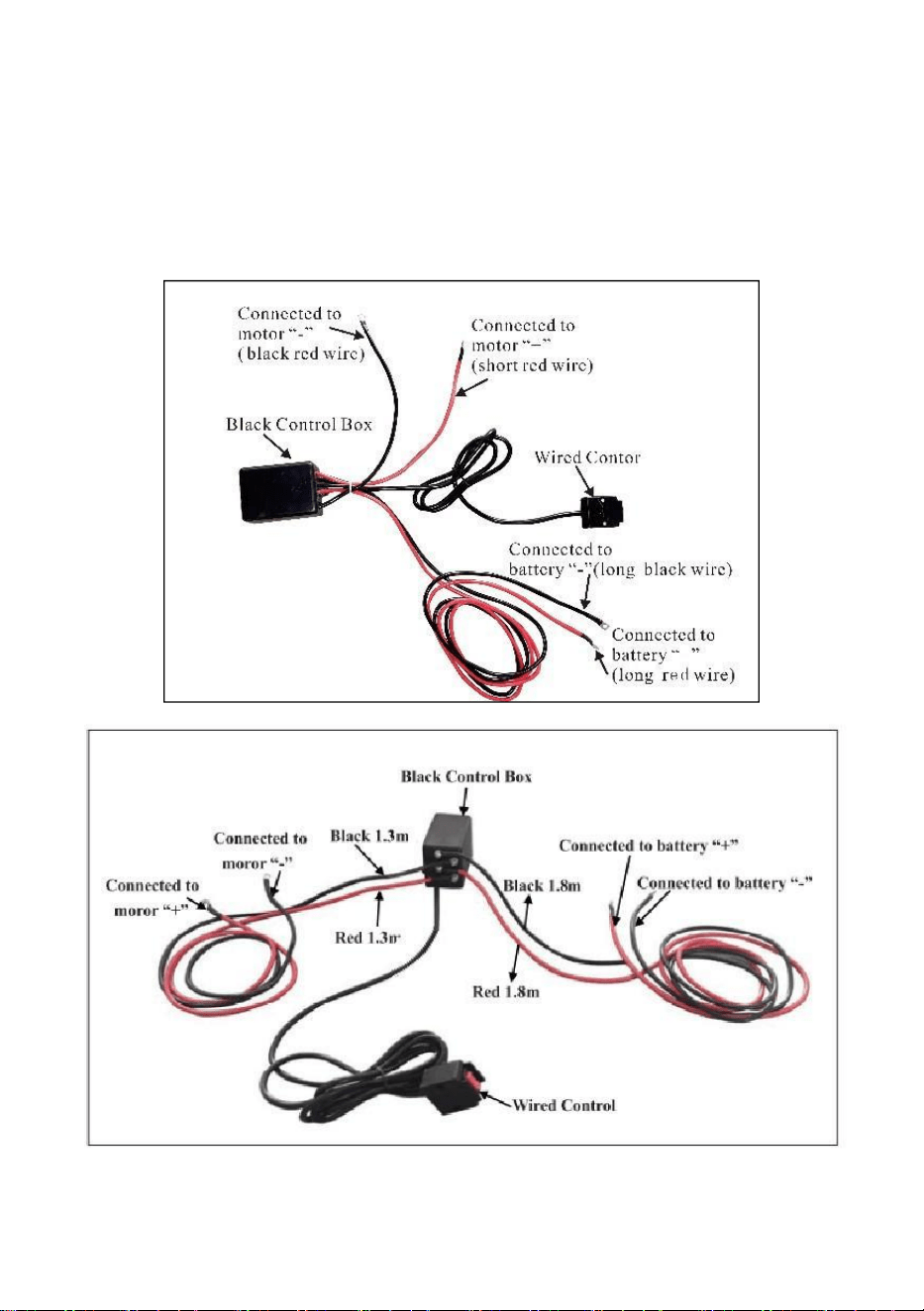
- 17 -
Schritt (1)
Führen Sie die kurzen rot und schwarz farbcodierten Kabel zum
Motor.
Führen Sie die langen, rot und schwarz farbcodierten Kabel zur
Batterie.
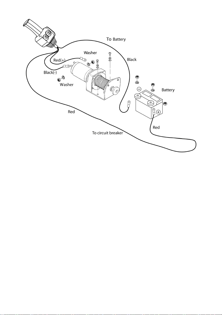
- 18 -
Schritt ( 2 )
Überprüfen Sie, dass die gesamte Verkabelung keine scharfen
Kanten und Quetschstellen aufweist.
Sichern Sie lose Kabel mit Kabelbindern oder Isolierband.
Lassen Sie den Schalter niemals eingesteckt, wenn die Winde nicht
verwendet wird.

- 19 -
PRODUCT INSTRUCTIONS
Bevor Sie die Funktion der Winde testen, rollen Sie unbedingt
etwa zwei Fuß Drahtseil ab.
PROBEFAHRT
5. Überprüfen Sie noch einmal, ob die gesamte Verkabelung korrekt ist
und keine freiliegenden Anschlüsse vorhanden sind, die einen
Kurzschluss mit dem Fahrzeugrahmen verursachen können.
6. Drehen Sie den Zündschlüssel in die Position „ON“. Überprüfen Sie die
Winde auf ordnungsgemäße Funktion.
FREIER SPULENBETRIEB
Ziehen Sie den Kupplungsknopf und drehen Sie ihn in die Position „Frei“.
Wenn das Drahtseil belastet ist, lässt sich der Kupplungsknopf
möglicherweise nicht leicht herausziehen. BENUTZEN SIE DEN
KUPPLUNGSKNOPF NICHT MIT GEWALT. Lösen Sie die Spannung der
Kupplung, indem Sie etwas Drahtseil herausziehen. Lassen Sie die
Kupplung los, ziehen Sie das Drahtseil heraus und befestigen Sie es am
Anker oder an der Last. Überprüfen Sie, ob noch mindestens fünf (5)
Windungen Drahtseil auf der Trommel vorhanden sind. Kuppeln Sie die
Trommel wieder ein, indem Sie den Kupplungsknopf wieder in die Position
„Eingekuppelt“ bringen. Aktivieren Sie die Winde in der Kabelausfahrt
kurzzeitig, um die Drehrichtung der Trommel zu überprüfen. Wenn sich die
Trommel in die falsche Richtung dreht, überprüfen Sie Ihre Verkabelung
erneut.
Achtung: Drehen Sie den Kupplungsknopf entsprechend den Pfeilen
und Anweisungen darauf, um die Windengetriebe ein- oder
auszukuppeln.
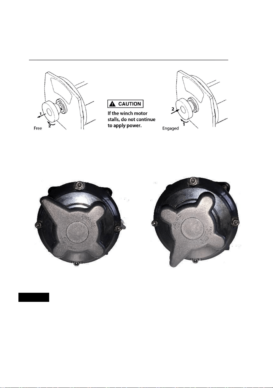
- 20 -
Achtung: Die Kupplung muss vor dem Windenbetrieb vollständig
eingerückt sein. Betätigen Sie den Kupplungsknopf niemals, während
sich die Trommel dreht.
BESCHÄFTIGT: FREIES SPULEN:
Drahtseil
11. Die Lebensdauer des Drahtseils hängt direkt von der Pflege ab, die es
erhält. Das Drahtseil einer neuen Winde und alle Ersatzseile sollten vor
der Verwendung der Winde mit einer Mindestlast von 100 Pfund neu
aufgespult werden. Andernfalls kann das Drahtseil beschädigt werden.
Überprüfen Sie das Drahtseil vor der Verwendung. Gequetschte,
eingeklemmte, ausgefranste oder geknickte Stellen verringern die

- 21 -
Tragfähigkeit erheblich. Ersetzen Sie beschädigte Drahtseile.
12. Verhindern Sie Knicke, bevor sie entstehen.
(g) Dies stellt den Beginn eines Knicks dar. Zu diesem Zeitpunkt sollte
das Drahtseil gerade gebogen werden.
(h) Das Drahtseil wurde gezogen und die Schlaufe hat
bis zum Knick gespannt. Das Drahtseil ist nun
dauerhaft
beschädigt und sollte nicht verwendet werden.
(i) Das Ergebnis des Knickens ist, dass jeder Strang
zieht
eine andere Menge, wodurch die Stränge unter
größte Spannung zum Brechen und Reduzieren der Belastung
Tragfähigkeit des Drahtseils.
13. Wenn das Drahtseil nach Gebrauch ohne Last neu aufgespult werden
muss, halten Sie die Leitung des Fernschalters in einer Hand und das
Drahtseil in der anderen. Beginnen Sie so weit vom Fahrzeug entfernt,
wie es der Fernschalter zulässt, aktivieren Sie den Schalter, gehen Sie
mehrere Fuß Seil hinein und lassen Sie den Schalter los. Wiederholen
Sie den Vorgang. Lassen Sie den Schalter immer los, bevor Ihre Hand
näher als vier Fuß an die Seilführung herankommt (falls vorhanden).
14. Stellen Sie sicher, dass das Drahtseil gleichmäßig und straff auf der
Trommel verteilt ist. Bei einer locker gewickelten Trommel kann sich
das Drahtseil in die Seillagen auf der Trommel einarbeiten und sich
verkeilen.
15. Es ist nicht ratsam, das Drahtseil zu fetten oder zu ölen, da
Schmutzverunreinigungen die Lebensdauer des Drahtseils verkürzen.
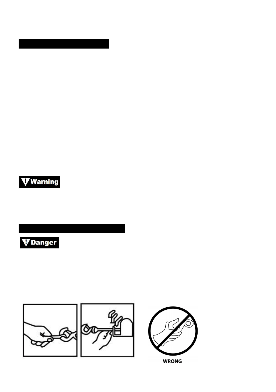
- 22 -
Ersetzen Sie das Drahtseil
11. Wenn das Drahtseil abgenutzt ist oder Anzeichen von Litzenbrüchen
zeigt, muss es vor der Wiederverwendung ausgetauscht werden.
Entfernen Sie dazu das defekte Seil durch Freispulen. Entfernen Sie
die Schraube an der Trommel und lassen Sie das Seil los.
12. Führen Sie das Ende des neuen Seils ein und ziehen Sie die Schraube
fest an.
13. Betätigen Sie die Kupplung und spulen Sie das neue Seil auf die
Trommel, wobei Sie das Seil beim Aufspulen unter Spannung halten.
Stellen Sie sicher, dass das Seil in der Unterwindposition aufgespult
wird.
Ersetzen Sie das Drahtseil nur durch das vom Hersteller
empfohlene identische Ersatzteil.
VORBEREITUNG DES WEINCH
Tragen Sie dicke Lederhandschuhe, wenn Sie mit
Drahtseilen arbeiten, auch wenn Sie Handschuhe tragen. Verwenden Sie
beim Umgang mit dem Haken immer einen Handschutz (siehe Abbildung
12). Stecken Sie niemals Ihre Finger in den Haken. Das Einstecken von
Fingern in den Haken kann zu Verletzungen führen.

- 23 -
Abbildung 12
1.Beim Verankern des Zugfahrzeugs die Feststellbremse anziehen und die
Räder blockieren oder mit Keilen sichern. Die Fußbremse des Fahrzeugs
gedrückt halten und bei Automatik- und Handschaltgetrieben den Leerlauf
einlegen.
Überprüfen Sie Schalter und Verkabelung auf Risse,
eingeklemmte Stellen, ausgefranste Drähte oder lose Verbindungen. Ein
beschädigtes, kurzgeschlossenes Kabel kann dazu führen, dass die Winde
sofort nach dem Einstecken in die Steckdose läuft.
1.Wenn Sie den Fernschalter im Fahrzeug verwenden, führen Sie ihn
immer durch ein Fenster, um ein Einklemmen des Kabels in der Tür zu
vermeiden.
WINDEN
Berühren Sie niemals das Drahtseil oder den Haken, wenn
diese unter Spannung oder Last stehen. Auch im Ruhezustand kann das
Drahtseil unter Spannung stehen. Führen Sie ein unter Spannung
stehendes Drahtseil niemals mit den Händen auf die Trommel (siehe Abb.
13).
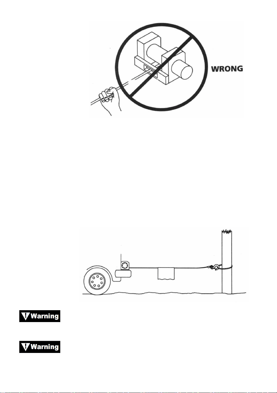
- 24 -
Abbildung 13
1. Winde mit mindestens fünf Wicklungen Drahtseil um die Windentrommel.
Bei weniger Wicklungen könnte sich das Drahtseil unter Last von der
Trommel lösen.
2. Wenn Sie eine Last ziehen, legen Sie eine Decke, Jacke oder Plane
über das Drahtseil in der Nähe des Hakenendes (siehe Abb. 14). Dadurch
wird das Zurückschnellen eines gerissenen Drahtseils verlangsamt und
schwere Verletzungen vermieden. Heben Sie die Motorhaube an, um die
Windschutzscheibe zu schützen.
Abbildung 14
Beachten Sie die Nenntragfähigkeit der Winde und
überschreiten Sie diese nicht.
Wenn die Last die maximale Nennzugkraft der Winde
überschreitet, schaltet der externe Leistungsschalter die Winde
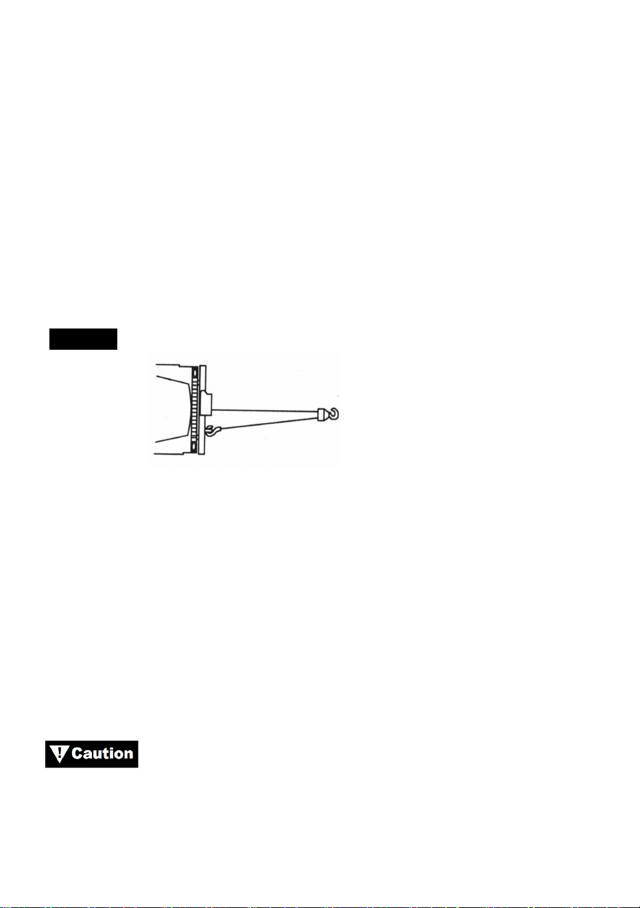
- 25 -
automatisch ab. Um den Leistungsschalter zurückzusetzen, lassen Sie
den Schalter los. Beachten Sie, dass die Winde erst wieder normal
gestartet werden kann, wenn die durch die übermäßige Belastung
aufgebaute Motorwärme abgekühlt ist.
1. Doppelte Leine mit einem Flaschenzug (siehe Abb. 15), um die
Belastung von Winde, Drahtseil und Batterie zu verringern. Durch die
doppelte Leine wird auch die Geschwindigkeit der Windenleine verringert.
Stellen Sie sicher, dass alle verwendeten Geräte die maximale
Seilzugkraft der Winde erfüllen. Bei doppelter Leine sollten Flaschenzüge
mindestens doppelt so stark sein wie die Seilzugkraft der Winde.
WINDEN
Abbildung 15
1.Wenn Sie einen Abschlepphaken für die Doppelverkleidung installieren,
sollte dieser am Fahrzeugrahmen befestigt werden.
2. Durch die Ausstattung der Winde mit einer Seilführung wird der
Verschleiß des Drahtseils beim Winkelziehen verringert.
3. Ziehen Sie so gerade wie möglich, um die Ansammlung von Drahtseil an
einem Ende der Trommel zu verringern.
4. Während des Windenbetriebs sollte der Fahrzeugmotor laufen. Wenn
bei ausgeschaltetem Motor längere Windenarbeiten durchgeführt werden,
ist die Batterie möglicherweise zu schwach, um den Motor neu zu starten.
Verwenden Sie einen Flaschenzug, um das Winden in
scharfen Winkeln zu vermeiden. Ungleichmäßige Lagenbildung kann zu
schweren Schäden an Winde und Drahtseil führen. Dies kann durch
Sichern der Ladung, Abspulen des Drahtseils und Neupositionieren am

- 26 -
anderen Ende der Trommel behoben werden.
Lösen Sie die Kupplung nicht unter Last. Wenn Ihre Winde
mit einer Freilaufkupplung ausgestattet ist, achten Sie darauf, dass beim
Lösen der Kupplung keine Spannung auf dem Drahtseil liegt. Bevor Sie
eine Last mit der Winde ziehen, stellen Sie sicher, dass die Kupplung
vollständig eingerückt ist.
Verwenden Sie die Winde, um die Last zu bewegen.
Versuchen Sie nicht, die Winde durch Bewegen des Fahrzeugs zu
unterstützen. Die Kombination aus Winde und Fahrzeug könnte das
Drahtseil überlasten und die Last könnte die Winde beschädigen.
Verlassen Sie sich niemals darauf, dass die Winde eine Last
an Ort und Stelle hält. Keine unserer Winden ist für Lasthalteanwendungen
ausgelegt und kann sich während des Transports der Last aufgrund von
Stoßbelastungen abwickeln oder versagen. Die Last sollte mit anderen
Mitteln gesichert und der Windenhaken von der Last gelöst werden.
TAKELWERK
Nehmen Sie sich beim Aufrüsten Zeit und berücksichtigen
Sie einen angemessenen Sicherheitsfaktor. Unsachgemäßes Aufrüsten
kann zu Schäden an Fahrzeug und Ausrüstung führen. Es kann auch zu
Verletzungen führen.
7. Hantieren Sie niemals mit dem Drahtseil oder der Takelage, während
sich jemand anderes am Steuerschalter befindet.
8.
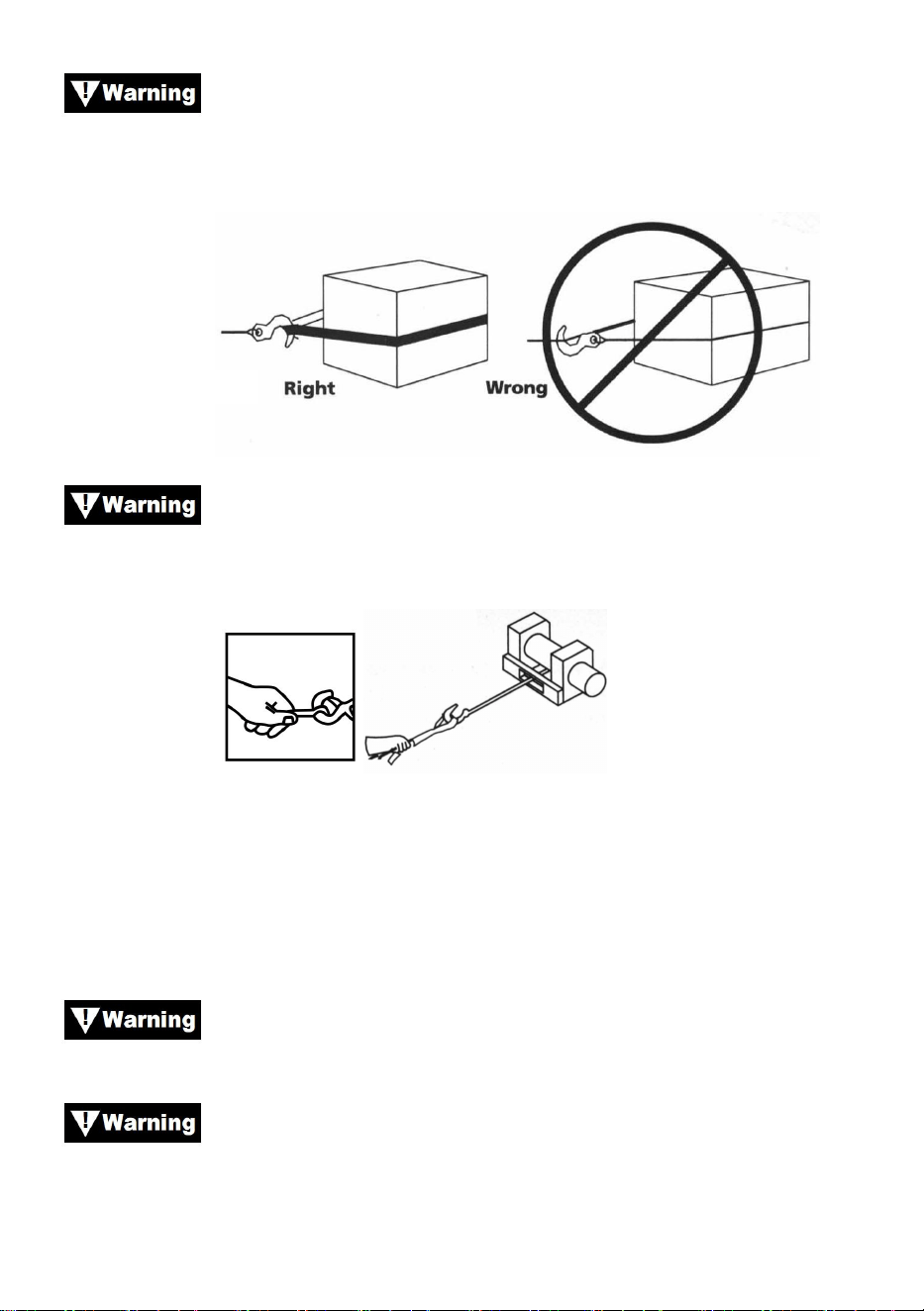
- 27 -
Verwenden Sie eine Nylonschlinge, wenn Sie das Drahtseil
an einem Ankerpunkt befestigen. Befestigen Sie den Haken nicht wieder
am Drahtseil. Dies kann zum Reißen des Drahtseils führen.
Abbildung 16
Benutzen Sie immer den Handschutz (siehe Abb.17). Halten
Sie den Haken nicht mit der Hand fest. Dies ist nicht nur beim Einrollen des
Drahtseils wichtig, sondern auch beim Abnehmen des Drahtseils von der
Winde unter Strom.
Abbildung 17
9. Lassen Sie die Winde periodisch laufen, um das Drahtseil zu straffen.
Wenn Sie einen Flaschenzug verwenden, achten Sie darauf, dass das
Drahtseil in allen Rollen richtig läuft, bevor Sie eine Last anlegen.
Die Kupplung darf nicht wieder eingeschaltet werden,
während die Winde läuft.
Bedienen Sie die Winde immer mit freier Sicht auf den
Windenvorgang. Verdecken Sie niemals Warn- und Hinweisschilder.
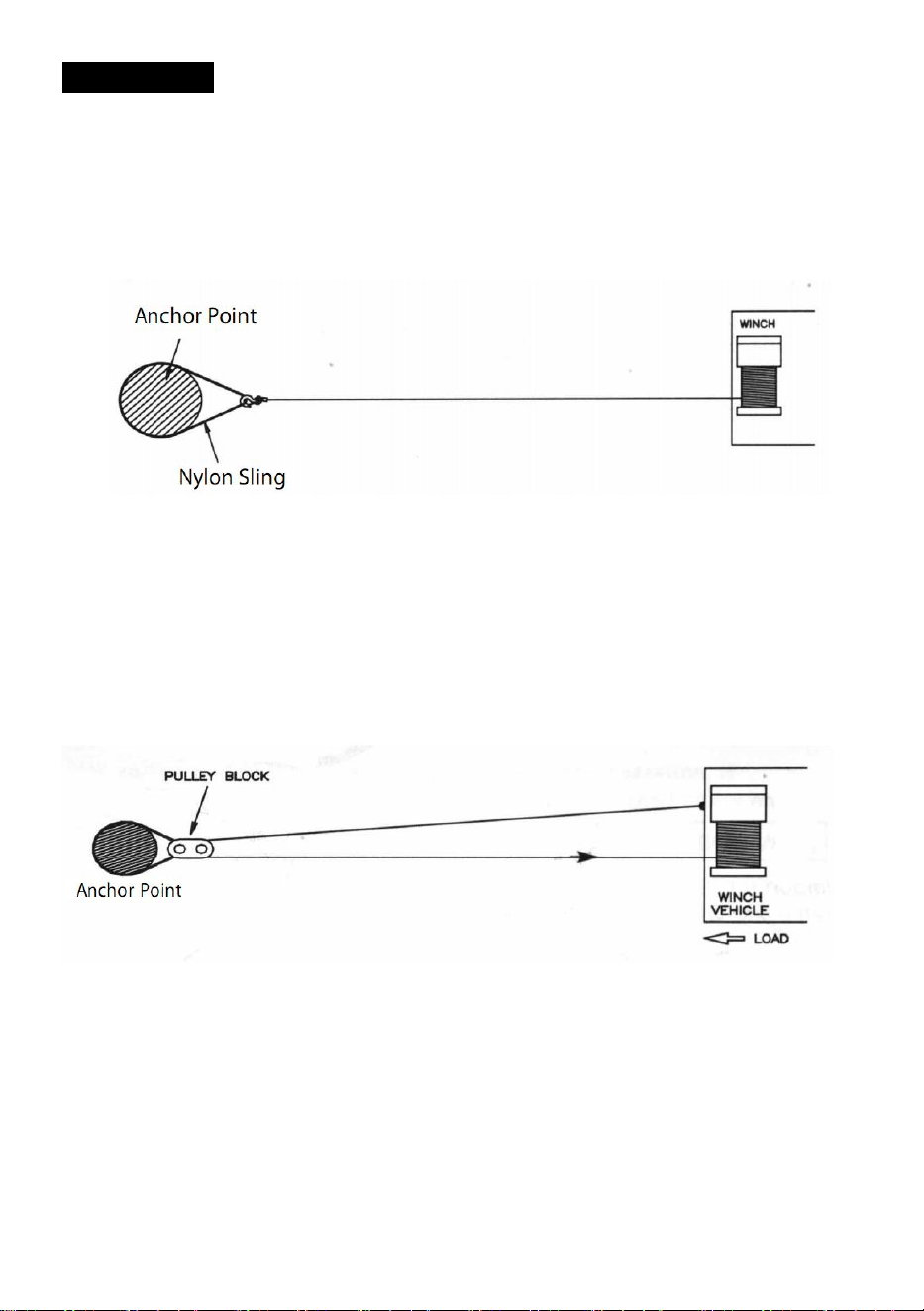
- 28 -
TAKELWERK
3. Abbildung 18 zeigt die am häufigsten verwendete Takelage. Eine
Nylonschlinge dient zum Schutz des Baumes, wenn er als Anker
verwendet wird, und das Drahtseil wird zur Verwendung der Schlinge
befestigt. Die Verwendung einer Kette oder eines Drahtseils wird nicht
empfohlen, da der Baum dadurch beschädigt werden könnte.
Abbildung 18
14. Abbildung 19 zeigt eine Takelagemethode, mit der ein mechanischer
Vorteil erzielt wird. Durch die Verwendung eines Flaschenzugs lässt
sich die Zugkraft der Leine fast verdoppeln. (Bitte beachten Sie, dass
der Flaschenzug nicht im Lieferumfang enthalten ist.)
Abbildung 19
15. Abbildung 20 zeigt die Verwendung eines Flaschenzugs zum Ändern
der Zugrichtung. Ein mechanischer Vorteil lässt sich erzielen, indem
man einen Flaschenzug mit einem Schäkel an der Nylonschlinge
befestigt und das Drahtseil zum Ankerpunkt führt.
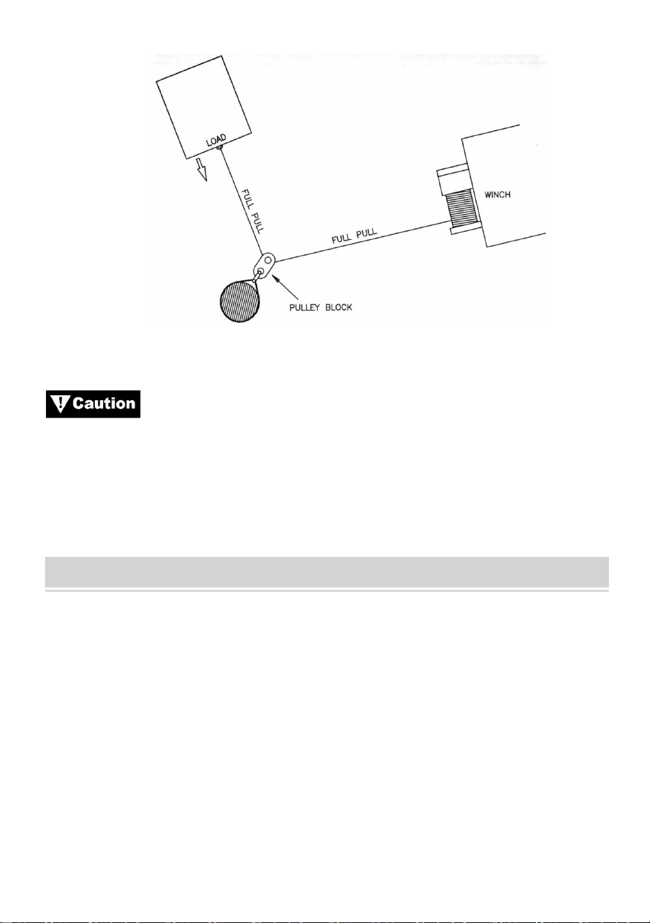
- 29 -
Abbildung 20
Ausrüstungsgegenstände wie Flaschenzüge, Haken,
Flaschenzüge, Gurte usw. müssen die richtige Größe und Belastbarkeit
aufweisen und regelmäßig auf Schäden überprüft werden, die ihre
Festigkeit beeinträchtigen könnten.
MAINTAINNENCE
1) Überprüfen Sie regelmäßig den festen Sitz der Befestigungsschrauben
und elektrischen Anschlüsse. Entfernen Sie allen Schmutz oder Korrosion
und halten Sie das Gerät stets sauber.
2) Versuchen Sie nicht, das Getriebe zu zerlegen. Reparaturen sollten
vom Hersteller oder einem autorisierten Servicezentrum durchgeführt
werden.
3) Das Getriebe wurde mit einem Hochtemperatur-Lithiumfett geschmiert
und im Werk versiegelt. Eine interne Schmierung ist nicht erforderlich.

- 30 -
TROUBLE SHOOTING
Problembeschreibung
Mögliche Ursachen
Korrekturmaßnahme
Motor läuft nicht oder nur
in eine Richtung
1.Schalter funktioniert
nicht
2. Defekte Kabel oder
schlechte Verbindung
3.Beschädigter Motor
1. Schalter ersetzen
2. Überprüfen Sie, ob die
Verbindung schlecht ist
3.Motor ersetzen oder
reparieren
Motor läuft extrem heiß
1. Lange Betriebsdauer
2.fehlgeschlagen oder
entfernt
Überlast
3.Beschädigter Motor
1.niedrig bis kühl
2. Überlastung beheben oder
beheben
3.Motor platzieren oder
reparieren
Motor läuft, aber mit
unzureichender Leistung
oder
Leitungsgeschwindigkeit
1.Schwache Batterie
2. Batterie-Windenkabel
zu lang
3. Schlechte
Batterieverbindung
4. Schlechter Boden
5.Beschädigter Motor
1.Laden Sie die Batterie auf
oder ersetzen Sie sie und
überprüfen Sie das
Ladesystem.
2.Halten Sie die Winde
innerhalb der von den
Anschlussdrähten
vorgegebenen Entfernung.
3. Überprüfen Sie die
Batteriepole auf Korrosion und
reinigen Sie sie bei Bedarf
4. Anschlüsse überprüfen und
reinigen
5.Motor platzieren oder
reparieren

- 31 -
Winde läuft rückwärts
1.tor Drähte vertauscht
2. Juckreizdrähte
vertauscht
3. Batterieschalter falsch
eingebaut
1. Verkabelung überprüfen
2. Verkabelung prüfen
3.eck Batterieanschlüsse
Motor läuft, aber Trommel
dreht sich nicht
1.Kupplung nicht
eingerückt
1. Kupplung betätigen
Winde rollt
1.Übermäßige Belastung
1. Last reduzieren oder Leitung
verdoppeln
Motor läuft, bleibt aber
stehen
1. Überlastung
1.Abkühlen lassen


Tecnico Supporto e certificato di garanzia elettronica www.vevor.com/support
ARGANO ELETTRICO
MODELLO: P2000-1/P3000-1C/P4000-1D/P4000-1W
We continue to be committed to provide you tools with competitive price.
"Save Half", "Half Price" or any other similar expressions used by us only represents an
estimate of savings you might benefit from buying certain tools with us compared to the major
top brands and does not necessarily mean to cover all categories of tools offered by us. You
are kindly reminded to verify carefully when you are placing an order with us if you are
actually saving half in comparison with the top major brands.


- 1 -
MODELLO: P2000-1/P3000-1C/P4000-1D/P4000-1W
Have product questions? Need technical support? Please feel free to
contact us:
Technical Support and E-Warranty Certificate
www.vevor.com/support
NEED HELP? CONTACT US!
This is the original instruction, please read all manual instructions
carefully before operating. VEVOR reserves a clear interpretation of our
user manual. The appearance of the product shall be subject to the
product you received. Please forgive us that we won't inform you again if
there are any technology or software updates on our product.
ELECTRIC WINCH
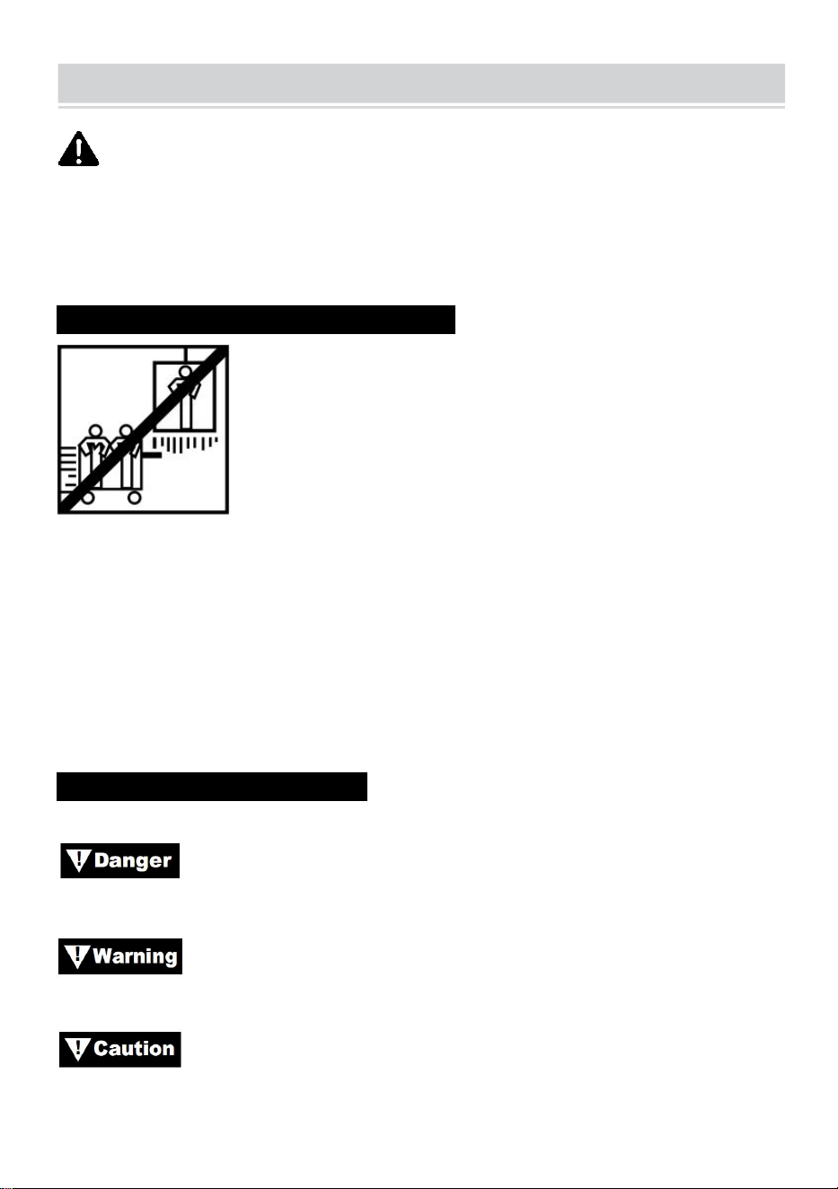
- 2 -
SAFE INSTRUCTIONS
ATTENZIONE: leggere attentamente e comprendere tutte le
ISTRUZIONI DI MONTAGGIO E FUNZIONAMENTO prima di utilizzare il
prodotto. La mancata osservanza delle norme di sicurezza e di altre
precauzioni di sicurezza di base può causare gravi lesioni personali.
INFORMAZIONI SULL'APPLICAZIONE N
Questo argano è progettato per spostare un carico a livello del suolo o in
salita. Non è progettato né inteso per il sollevamento.
Questo argano non deve essere utilizzato per sollevare o spostare
persone.
Questo argano è destinato all'uso intermittente a causa delle
caratteristiche di accumulo di calore di vari componenti. Se l'estremità del
motore diventa eccessivamente calda al tatto, interrompere l'uso del
argano e lasciare raffreddare il motore.
PRECAUZIONI DI SICUREZZA
In tutto il manuale troverete annotazioni con le seguenti intestazioni:
: Indica una situazione di pericolo imminente che, se non
evitata, provocherà morte o lesioni gravi.
: Indica una situazione potenzialmente pericolosa che, se non
evitata, potrebbe provocare morte o lesioni gravi.
: Indica una situazione potenzialmente pericolosa che, se non
evitata, può causare lesioni lievi o moderate. Questa notazione è utilizzata
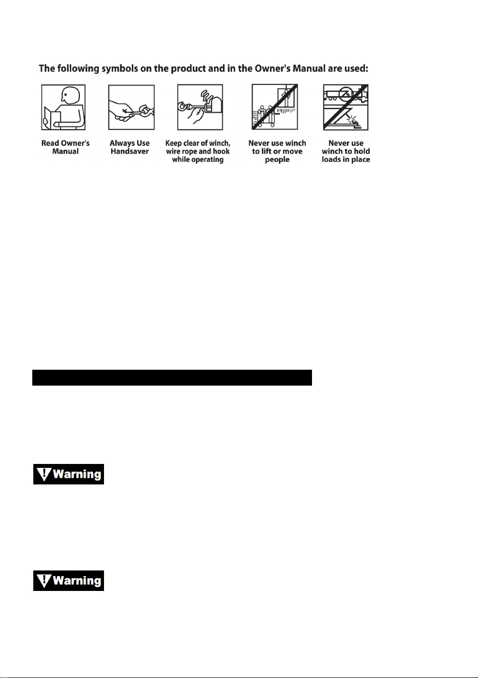
- 3 -
anche per mettere in guardia contro pratiche non sicure.
Nota: indica informazioni aggiuntive sulle procedure di installazione
e funzionamento del verricello.
Nota bene : il verricello è progettato principalmente per applicazioni
intermittenti. Questo verricello non è progettato per essere utilizzato in
applicazioni industriali o di sollevamento.
Utilizzare sempre il salvamani sul gancio.
Tenersi lontani dall'argano, dalla fune metallica e dal gancio durante l'uso.
Non utilizzare mai l'argano per sollevare o spostare persone.
Non utilizzare mai l'argano per tenere fermi i carichi.
INFORMAZIONI GENERALI SULLA SICUREZZA
Il tuo verricello è una macchina molto potente. Se usato in modo non
sicuro o improprio, potrebbe causare danni alla proprietà o lesioni
personali.
La responsabilità per l'installazione e il funzionamento sicuri
del verricello e la prevenzione di lesioni personali e danni alla proprietà
ricade in ultima analisi su di te, l'operatore. Non esiste sostituto per l'uso
del buon senso e della cautela nell'uso di un verricello.
Il cavo metallico potrebbe rompersi prima che il verricello
vada in stallo.
Per carichi pesanti, utilizzare un blocco puleggia per ridurre il carico sul
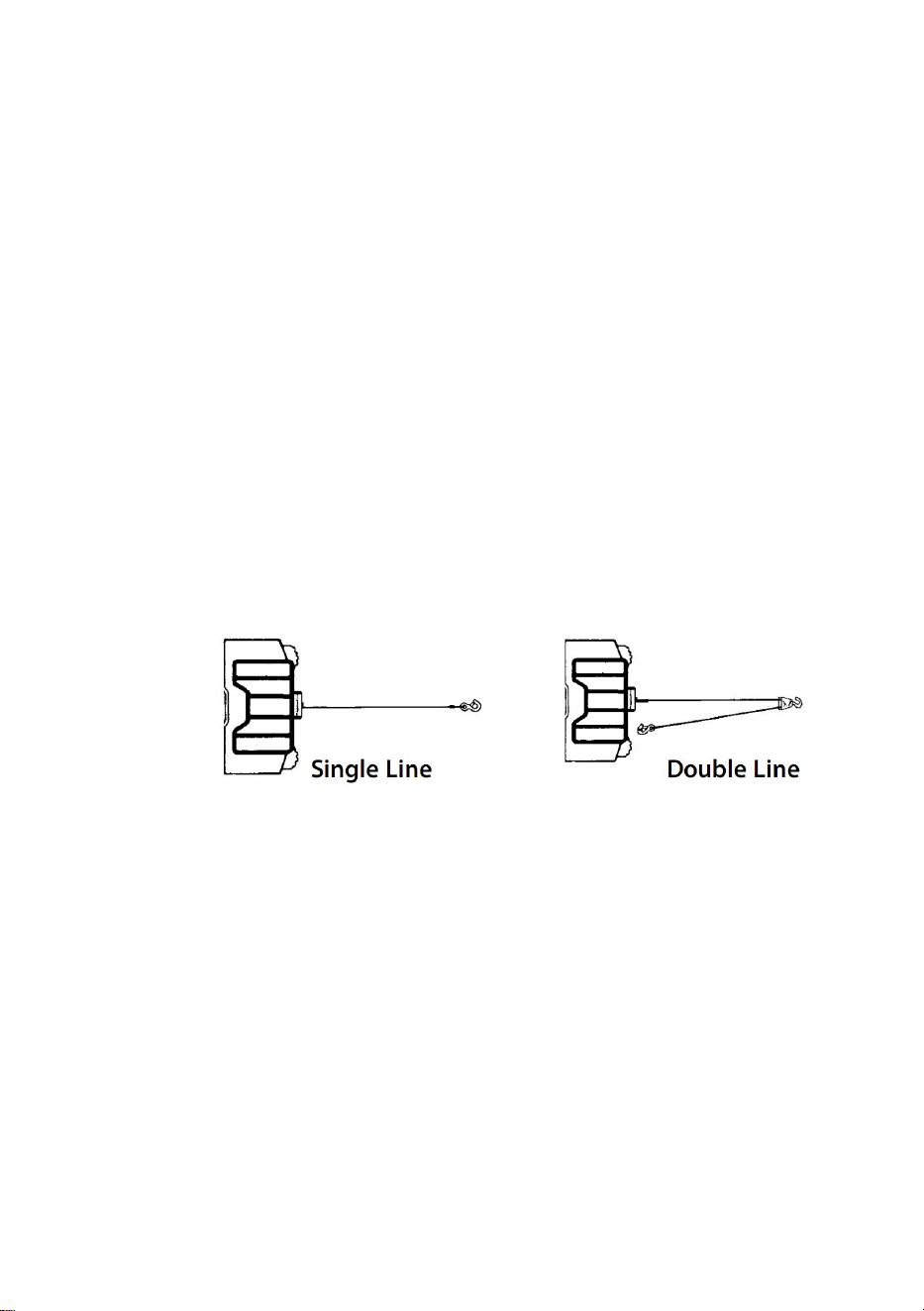
- 4 -
cavo metallico.
88. La capacità massima di carico di lavoro è sullo strato di fune metallica
più vicino al tamburo. NON SOVRACCARICARE. NON TENTARE
TIRATE PROLUNGATE CON CARICHI PESANTI. I sovraccarichi
possono danneggiare il verricello e/o la fune metallica e creare
condizioni operative non sicure. PER CARICHI OLTRE 1/2 DELLA
CAPACITÀ NOMINALE, RACCOMANDIAMO L'USO DEL PULLY
BLOCK OPZIONALE PER DOPPIO LINEAMENTO DELLA FUNE
METALLICA (Figura 1). Ciò riduce il carico sul verricello e la
sollecitazione sulla fune metallica di circa il 50%. Fissare il gancio alla
parte portante. Il motore del veicolo deve essere acceso durante il
funzionamento del verricello. Se si esegue un sollevamento
considerevole a motore spento, la batteria potrebbe essere troppo
debole per riavviare il motore.
Figura 1.
89. DOPO AVER LETTO E COMPRESO QUESTO MANUALE, IMPARA A
USARE IL TUO VERRICELLO. Dopo aver installato il verricello, fai
pratica con il suo utilizzo in modo da averne familiarità quando
necessario.
90. NON "spostare" il veicolo per aiutare il verricello a tirare il carico. La
combinazione del verricello e del veicolo che tirano insieme potrebbe
sovraccaricare il cavo metallico e il verricello.
91. TENETEVI SEMPRE LONTANO DA FUNI METALLICHE, GANCI E
VERRICELLI. NELL'IMPROBABILE CASO DI GUASTO DI
QUALSIASI COMPONENTE, È MEGLIO ESSERE FUORI DALLA
ZONA DEI DANNI.
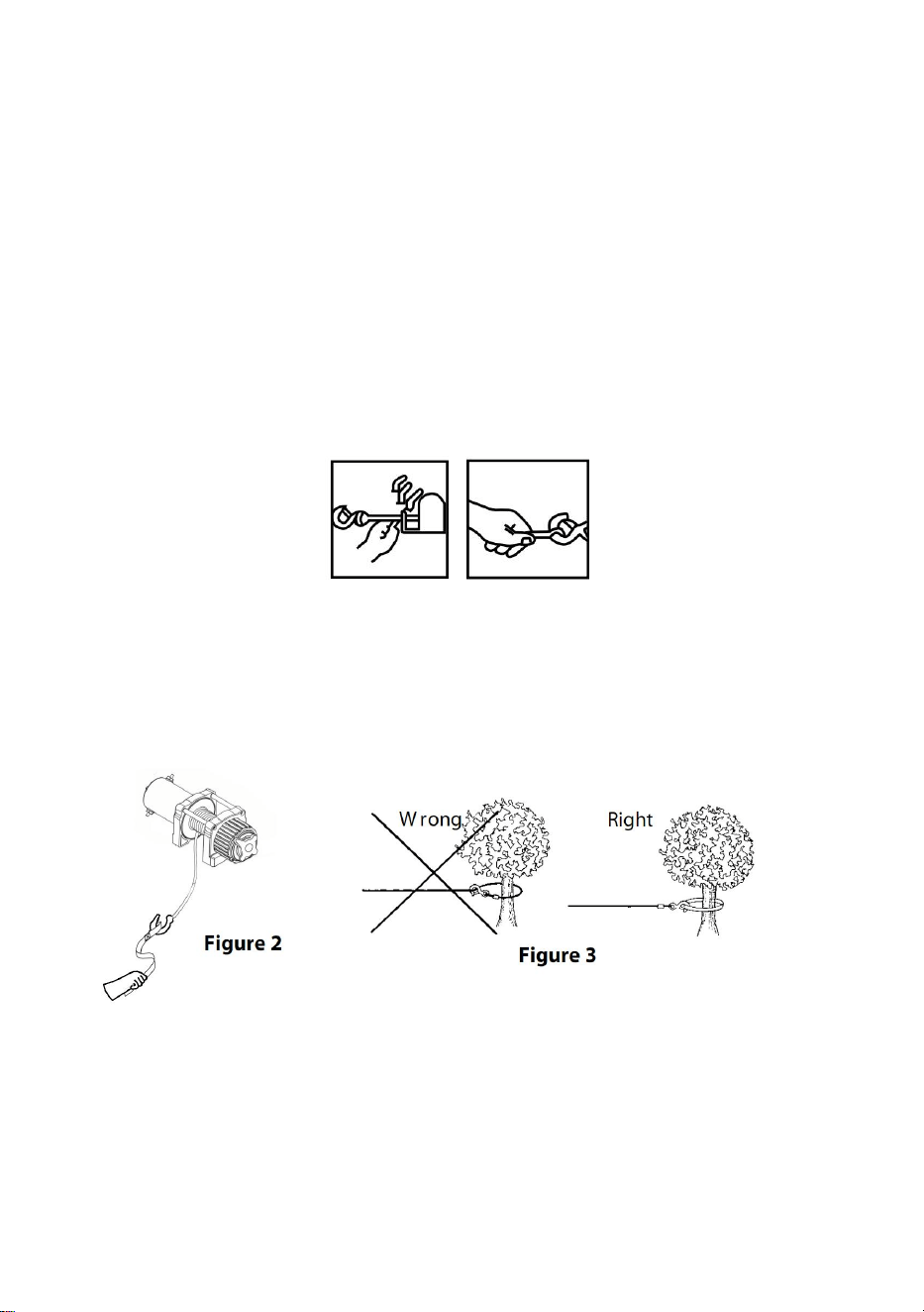
- 5 -
92. Ispezionare frequentemente il cavo metallico e l'attrezzatura. Un cavo
metallico sfilacciato con fili rotti deve essere sostituito
immediatamente.
93. Utilizzare guanti di pelle spessa quando si maneggia il cavo metallico.
Non lasciare che il cavo metallico scivoli tra le mani.
94. Non utilizzare mai il verricello con meno di 5 giri di fune metallica
attorno al tamburo del verricello, poiché l'elemento di fissaggio
terminale della fune metallica POTREBBE NON sopportare il carico
completo.
95. Non mettere mai il dito nel gancio. Se il dito rimanesse intrappolato nel
gancio, potresti perderlo .
96. UTILIZZARE SEMPRE IL SALVAMANI quando si guida il cavo
metallico dentro o fuori. (Vedere Figura 2).
97. NON RIAGGANCIARE MAI IL CAVO METALLICO SU SE STESSO
perché potresti danneggiarlo. Usa una fettuccia di nylon (Figura 3).
98. È una buona idea stendere una coperta pesante o una giacca sopra la
fune metallica vicino all'estremità del gancio quando si tirano carichi
pesanti (Figura 4). Se si verifica un guasto della fune metallica, il telo
fungerà da ammortizzatore e aiuterà a impedire che la fune si muova.

- 6 -
99. EVITARE TIRAGGI CONTINUI DA ANGOLI ESTREMI poiché ciò
causerebbe l'accumulo della fune metallica su un'estremità del
tamburo. Ciò potrebbe inceppare la fune metallica nel verricello,
danneggiando la fune o il verricello.
100. NON COPRIRE MAI LE ETICHETTE DI AVVERTENZA E LE
ISTRUZIONI.
101. Azionare sempre il verricello mantenendo una visuale libera
sull'operazione di sollevamento.
102. Attrezzature quali paranchi, ganci, carrucole, cinghie, ecc. devono
essere dimensionate in base all'attività di sollevamento e devono
essere periodicamente ispezionate per verificare che non vi siano
danni che potrebbero ridurne la resistenza.
103. NON RILASCIARE MAI LA FRIZIONE A BOBINA LIBERA
QUANDO C'È UN CARICO SUL VERRICELLO.
104. NON LAVORARE MAI SUL TAMBURO DEL VERRICELLO O
INTORNO AD ESSO QUANDO IL VERRICELLO È SOTTO CARICO.
105. NON UTILIZZARE IL VERRICELLO QUANDO SI È SOTTO
L'EFFETTO DI DROGHE, ALCOL O MEDICINALI.
106. SCOLLEGARE SEMPRE I CAVI DI ALIMENTAZIONE DEL
VERRICELLO DALLA BATTERIA PRIMA DI LAVORARE NEL
TAMBURO DEL VERRICELLO O INTORNO AD ESSO, in modo che il
verricello non possa essere attivato accidentalmente.
107. Quando si sposta un carico, allentare lentamente la fune metallica
finché non diventa tesa. Fermarsi, ricontrollare tutti i collegamenti del
verricello. Assicurarsi che il gancio sia correttamente posizionato. Se si
utilizza una fettuccia di nylon, controllare l'attacco al carico.
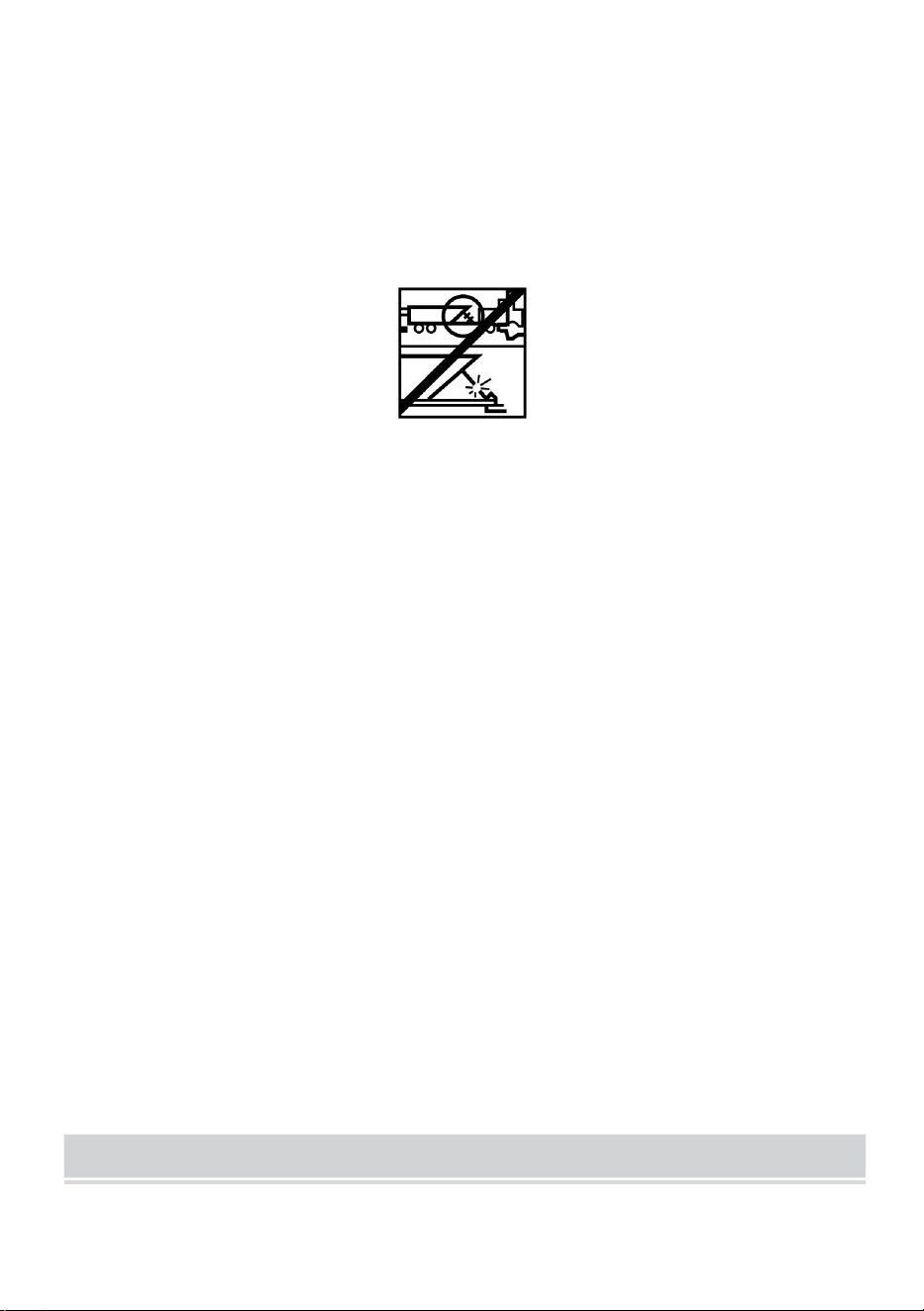
- 7 -
108. Quando si utilizza il verricello per spostare un carico, mettere la
trasmissione del veicolo in folle, azionare il freno e bloccare tutte le
ruote.
109. NON USARE IL VERRICELLO PER FISSARE I CARICHI IN
POSIZIONE. Utilizzare altri mezzi per fissare i carichi, come cinghie di
fissaggio.
110.UTILIZZARE SOLO INTERRUTTORI, TELECOMANDI E
ACCESSORI APPROVATI DALLA FABBRICA. L'uso di componenti
non approvati dalla fabbrica può causare lesioni o danni alla proprietà.
111.NON LAVORARE A MACCHINA O SALDARE NESSUNA PARTE DEL
VERRICELLO. Tali modifiche potrebbero indebolire l'integrità
strutturale del verricello.
112.NON COLLEGARE IL VERRICELLO ALLA CORRENTE DOMESTICA
DA 110 V CA O ALLA RETE ELETTRICA DA 220 V, IN QUANTO
POTREBBE VERIFICARSI FOLGORAZIONE DEL VERRICELLO O
SCOSSE MORTALI.
113.Non applicare mai carichi d'urto al verricello o alla fune metallica.
114.Prestare attenzione quando si tira o si abbassa un carico su e giù da
una rampa o da un pendio. Tenere persone, animali domestici e
proprietà lontano dal percorso del carico.
115.Per garantire un funzionamento sicuro, il gruppo dell'interruttore deve
essere mantenuto libero da sporcizia e umidità.
116.Per impedire l'uso non autorizzato del verricello, rimuovere il comando
a sospensione e riporlo in un luogo pulito e asciutto, come il vano
portaoggetti.
PRODUCT SPECIFICATION

- 8 -
Contenuto della confezione
P2000-1
P3000-1C
P4000-1D
Modello
P4000-1W
Voltaggio
12 V CC
12 V CC
12 V CC
12 V CC
Potenza
nominale
0,95 CV
1,3 CV
2,2 CV
2,2 CV
Rapporto di
trasmissione
153
:
1
153
:
1
128.2
:
1
128.2
:
1
Lunghezza
del filo
1,8 milioni
1,8 milioni
1,8 milioni
1,8 milioni
Corda
Acciaio ,
5/32 pollici *
39 piedi
Acciaio ,
3/16 pollici *
39 piedi
Acciaio ,
1/4 pollice * 39
piedi
Sintetico ,
1/4 pollice * 39
piedi
Classificazion
e
IP
55
55
55
55
P2000-1
P3000-1C
P4000-1D
Modello
P4000-1W
Argano
elettrico
1
1
1
1
Model
SPEC.
Model
Parts

- 9 -
PRODUCT ASSEMBLY INSTRUCTIONS
MONTAGGIO DEL VERRICELLO
KIT DI MONTAGGIO
IL PRODUTTORE RACCOMANDA L'USO DI UN KIT DI MONTAGGIO
Scatola di
controllo
×
1
1
1
Controllo
remoto
senza fili
×
1
1
1
Controllore
della
maniglia
1
1
1
1
Guidacavo a
rulli
1
1
1
1
Staffa di
montaggio
1
1
1
1
Gancio a
forcella
1
1
1
1
Fascia rossa
1
1
1
1
Kit di viti
1
1
1
1
Manuale
1
1
1
1

- 10 -
PER UN MONTAGGIO SICURO SUL VOSTRO VEICOLO. I kit di
montaggio del verricello ATV sono normalmente inclusi nel pacchetto del
verricello. Se si sceglie di non acquistare un kit di montaggio, il verricello
deve essere fissato a una posizione di montaggio sicura e piana. Si noti
che il verricello potrebbe non essere in grado di funzionare in sicurezza
senza alcune attrezzature incluse nel kit.
Questo argano deve essere montato con la fune metallica
rivolta verso il basso (Figura 6).
Figura 6
Nota: è possibile, e non è raro o sconsigliato, montare il verricello in
posizioni diverse da quelle illustrate nel presente manuale di installazione.
Sebbene l'assetto di montaggio sia a tua discrezione, ricorda sempre che il
tuo verricello deve essere azionato con la fune metallica in un
orientamento sottoavvolto sul tamburo della fune metallica (Figura 1). Il tuo
verricello è progettato per FAR ENTRARE E FAR USCIRE la fune
metallica in una direzione. Non tentare di invertire il funzionamento del tuo
verricello.
INSTALLAZIONE DEL VERRICELLO
Nota : quando si installa un verricello, l'installazione potrebbe variare
leggermente dalle istruzioni e dagli schemi seguenti, a seconda del veicolo,
del verricello, del kit di montaggio o del supporto strutturale.

- 11 -
Prima di iniziare l'installazione del verricello, scollegare
la massa del veicolo e i cavi positivi dalla batteria.
REQUISITI ELETTRICI MINIMI
Assicuratevi di selezionare la batteria o l'alimentatore appropriati per
gestire questo verricello. Se il verricello è in uso intenso, si consiglia una
batteria ausiliaria e un alternatore per impieghi gravosi.
PROCEDURA DI INSTALLAZIONE:
PASSO (1)
Installare il kit di montaggio o preparare una posizione di montaggio piana
e sicura per il verricello per assicurarsi che il motore, il tamburo e la scatola
del cambio siano allineati correttamente. Seguire attentamente le istruzioni
incluse nel kit di montaggio.
Assicurarsi che il supporto strutturale sia sufficientemente
robusto da supportare la capacità nominale del verricello.
Nota: se non hai un kit di montaggio, dovrai praticare dei fori nel supporto
strutturale. Assicurati che il tuo supporto strutturale abbia uno spessore di
almeno 3/16" (5 mm).
Se per l'installazione sono necessari bulloni, dadi, rondelle e
altri elementi di fissaggio di lunghezza diversa, utilizzare sempre elementi
di fissaggio con grado di resistenza uguale o superiore a quello degli
elementi di fissaggio forniti.
Passo ( 2 )
Posizionare l'argano sui fori del kit di montaggio o del supporto strutturale.
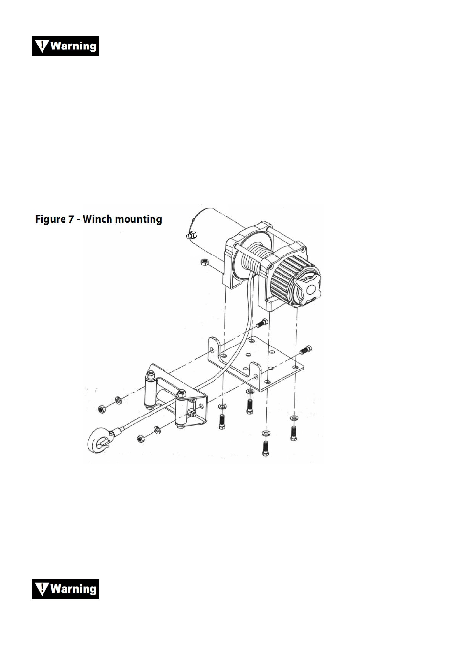
- 12 -
Quando si posiziona il verricello, assicurarsi che la fune
metallica si avvolga nella giusta rotazione sul tamburo. Il mancato
funzionamento del verricello nella direzione corretta può causare il
malfunzionamento del freno del verricello (se in dotazione) e/o il guasto del
verricello.
Passo (3)
Fissare il verricello (figura 7) al kit di montaggio o al supporto strutturale
utilizzando bulloni, rondelle elastiche e dadi quadrati forniti con il verricello.
Passo (4)
Fissare il passacavo a rulli (Figura 7) alla piastra di montaggio o al
supporto della struttura utilizzando la ferramenta in dotazione o utilizzando
due (2) bulloni in acciaio di trazione M8x 20L grado 8.8.
Assicurarsi che sia la piastra di montaggio sia la

- 13 -
ferramenta del verricello siano stati serrati correttamente.
Nessuna parte del veicolo (piastre di protezione, cablaggio,
luci ausiliarie, pneumatici, ecc.) deve impedire il funzionamento del
verricello. Durante il montaggio, controllare che tutte le parti del veicolo e
del verricello funzionino liberamente. Assicurarsi che la posizione di
montaggio del verricello non riduca significativamente l'altezza da terra.
MONTAGGIO SCATOLA SOLENOIDE
10. La scatola del solenoide scollega il verricello dalla batteria quando il
veicolo è spento.
11. La scatola del solenoide deve essere montata vicino alla batteria e in
un luogo il più possibile pulito e asciutto.
12. Assicurarsi che la posizione selezionata per la scatola del solenoide
garantisca sufficiente spazio libero da tutte le strutture metalliche,
come i tubi del telaio.
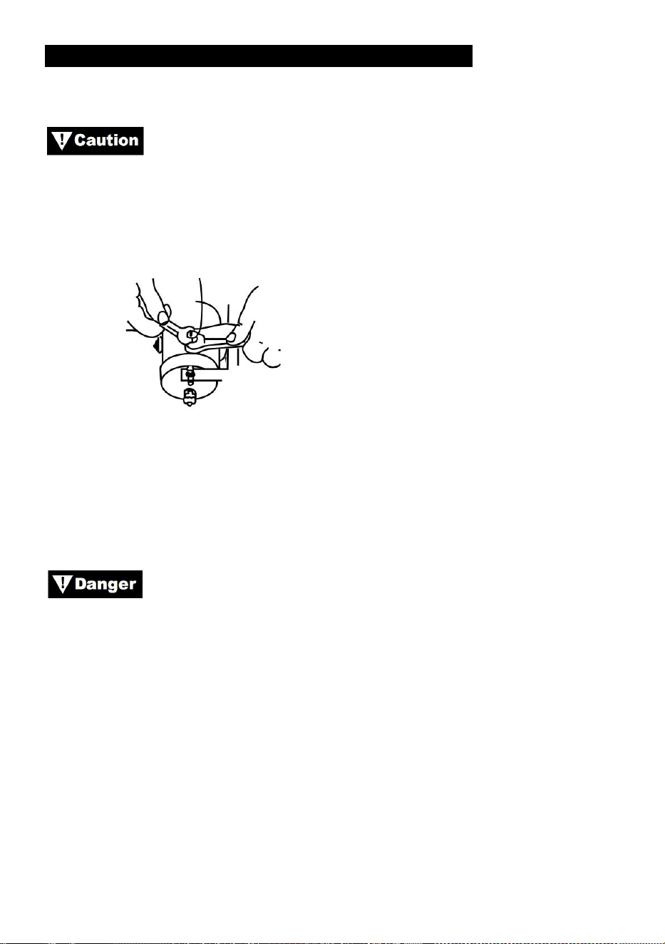
- 14 -
INSTALLAZIONE DELL'INTERRUTTORE A LEVETTA
APPLICAZIONI: SERIE ATV
Quando si collegano i fili ai terminali del motore o dello
slenoide, tenere fermo il dado interno con una chiave mentre si serra il
dado esterno con una seconda chiave. Non consentire ai terminali di
ruotare nei loro alloggiamenti. La rotazione può causare la rottura interna
del filo o il disallineamento delle parti (Figura 9).
Figura 9—Corretto serraggio dei terminali
Passo (1)
Prima di eseguire qualsiasi intervento elettrico, verificare che la massa del
veicolo e i cavi positivi della batteria siano scollegati.
NON TENTARE DI INSTALLARE CABLAGGI QUANDO LA
BATTERIA È COLLEGATA. Le batterie per autoveicoli contengono gas
infiammabili ed esplosivi. Indossare protezioni per gli occhi durante
l'installazione e rimuovere tutti i gioielli di metallo. Non chinarsi sulla
batteria durante i collegamenti.
Passo (2)
Instradare il cablaggio, fissandolo ai punti rigidi del veicolo mediante
fascette.
Nota: quando si instradano i cavi, i terminali appropriati devono essere
posizionati vicino alla batteria, al punto di montaggio dell'interruttore e al
verricello. I requisiti di installazione variano a seconda del veicolo e del
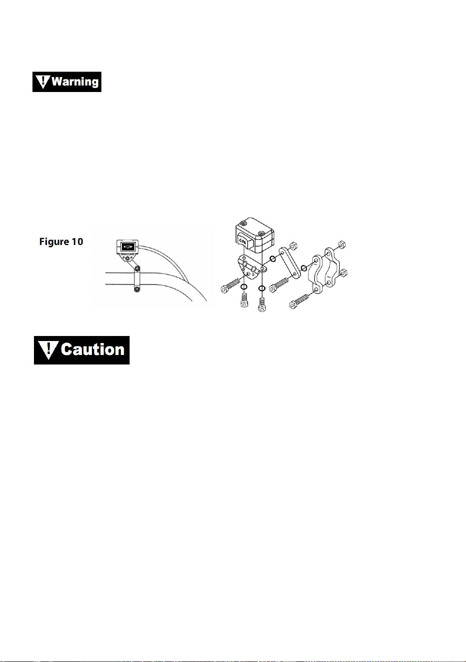
- 15 -
verricello. Assicurarsi che i cavi siano sufficientemente lunghi da
raggiungere la batteria, il punto di montaggio dell'interruttore e il verricello.
Assicurarsi che il cablaggio non interferisca o entri in contatto
con parti calde o in movimento del motore, delle sospensioni, dello sterzo,
dei freni o dello scarico.
Passo(3)
Utilizzando i morsetti, la staffa e l'hardware forniti, montare l'interruttore a
levetta in una posizione comoda. Vedere Figura 10.
UTILIZZARE SEMPRE LA STAFFA DI MONTAGGIO
DELL'INTERRUTTORE A LEVETTA, LE VITI E I DADI DI BLOCCAGGIO
FORNITI. Le lunghezze delle viti sono dimensionate per una corretta
penetrazione nella scatola dell'interruttore. Una penetrazione eccessiva
può causare cortocircuiti che potrebbero causare il surriscaldamento del
filo.
Passo (4)
Si consiglia di installare l'interruttore sul manubrio sinistro.
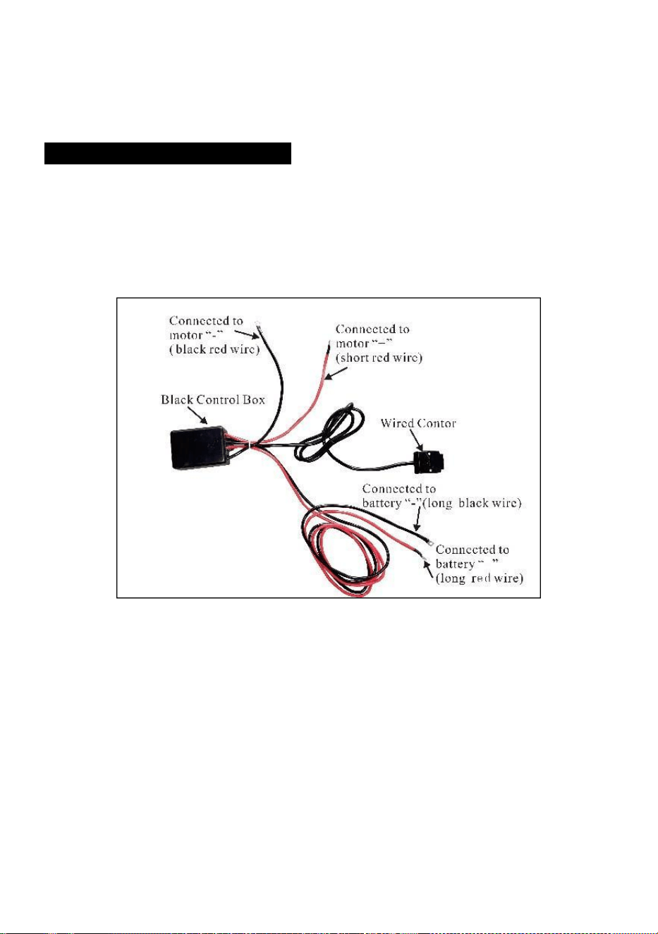
- 16 -
INSTALLAZIONE CABLAGGIO
Passo (1)
Instradare i fili corti colorati rosso e nero verso il motore.
Instradare i lunghi fili colorati rosso e nero verso la batteria.
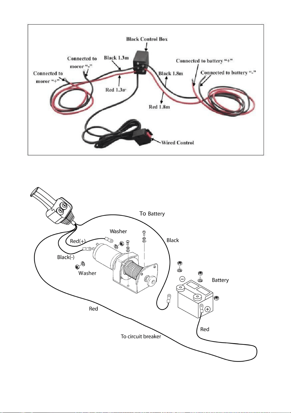
- 17 -

- 18 -
Passo ( 2 )
Controllare che tutti i cavi siano privi di spigoli vivi e punti di
schiacciamento.
Fissare i cavi allentati con fascette o nastro isolante.
Non lasciare mai l'interruttore collegato quando il verricello non è in
uso.
PRODUCT INSTRUCTIONS
Prima di testare il funzionamento del verricello, accertarsi di
srotolare circa due piedi di fune metallica.
PROVA SU STRADA
7. Controllare attentamente che tutto il cablaggio sia corretto e che non vi
siano terminali esposti che possano causare cortocircuiti con il telaio
del veicolo.
8. Girare la chiave di accensione in posizione ON. Controllare il corretto
funzionamento del verricello.
FUNZIONAMENTO A BOBINA LIBERA
Tirare e girare la manopola della frizione in posizione "Free". Se c'è un
carico sul cavo metallico, la manopola della frizione potrebbe non uscire

- 19 -
facilmente. NON FORZARE LA MANOPOLA DELLA FRIZIONE. Rilasciare
la tensione sulla frizione tirando fuori un po' del cavo metallico. Rilasciare
la frizione ed estrarre il cavo metallico e fissarlo all'ancora o al carico.
Controllare che ci siano almeno cinque 5 giri di cavo metallico rimasti sul
tamburo. Riagganciare il tamburo riportando la manopola della frizione in
posizione "Engaged". Attivare momentaneamente il verricello in Cable Out
per controllare la direzione di rotazione del tamburo. Se il tamburo ruota
nella direzione sbagliata, ricontrollare il cablaggio.
Attenzione: ruotare la manopola della frizione seguendo le frecce e le
istruzioni riportate sulla stessa per innestare o disinnestare gli
ingranaggi del verricello.
Attenzione: la frizione deve essere completamente innestata prima di
usare il verricello. Non innestare mai la manopola della frizione
mentre il tamburo gira.
IMPEGNATO: SPOILER LIBERO:

- 20 -
CAVO METALLICO
16. La durata del cavo metallico è direttamente correlata alla cura che
riceve. Il cavo metallico su un nuovo verricello e qualsiasi cavo
sostitutivo devono essere riavvolti sotto un carico minimo di 100 libbre
prima di utilizzare il verricello. La mancata osservanza di questa
precauzione causerà danni al cavo metallico. Ispezionare il cavo
metallico prima dell'uso. Aree schiacciate, pizzicate, sfilacciate o
attorcigliate riducono notevolmente la capacità di carico. Sostituire il
cavo metallico danneggiato.
17. Prevenire i problemi prima che si verifichino.
(j) Questo è l'inizio di un nodo. A questo punto, il cavo metallico
dovrebbe essere raddrizzato.
(k) La fune metallica è stata tirata e il cappio è
serrato fino a creare un nodo. Il cavo metallico è ora
permanentemente
danneggiato e non deve essere utilizzato.
(l) Il risultato dell'attorcigliamento è che ogni filo tira
una quantità diversa che causa i fili sotto

- 21 -
massima tensione per rompere e ridurre il carico
capacità del cavo metallico.
18. Quando è necessario riavvolgere il cavo metallico senza carico dopo
l'uso, tenere il cavo dell'interruttore remoto in una mano e il cavo
metallico nell'altra. Iniziare da una distanza dal veicolo il più possibile
ampia, attivare l'interruttore, camminare per diversi piedi di corda e
rilasciare l'interruttore. Ripetere il processo. Rilasciare sempre
l'interruttore prima che la mano si trovi a quattro piedi dal passacavo
(se installato).
19. Assicuratevi che il cavo metallico sia distribuito uniformemente e
strettamente sul tamburo. Un tamburo avvolto in modo lasco consente
al cavo metallico di farsi strada verso il basso negli strati di cavo
metallico sul tamburo e di incastrarsi.
20. Si sconsiglia di ingrassare o oliare il cavo metallico a causa della
contaminazione da sporco che ne ridurrà la durata.
SOSTITUIRE IL CAVO METALLICO
16. Se la fune metallica si è usurata o inizia a mostrare segni di rottura dei
fili, deve essere sostituita prima di essere riutilizzata. Per fare ciò,
rimuovere la fune difettosa tramite avvolgimento libero. Rimuovere il
bullone sul tamburo e rilasciare la fune.
17. Inserire l'estremità della nuova corda e fissare saldamente il bullone.
18. Innestare la frizione e riavvolgere la nuova fune sul tamburo
mantenendo la tensione sulla fune mentre si avvolge. Assicurarsi che
la fune si riavvolga in posizione sottovento.
Sostituire il cavo metallico solo con il pezzo di ricambio
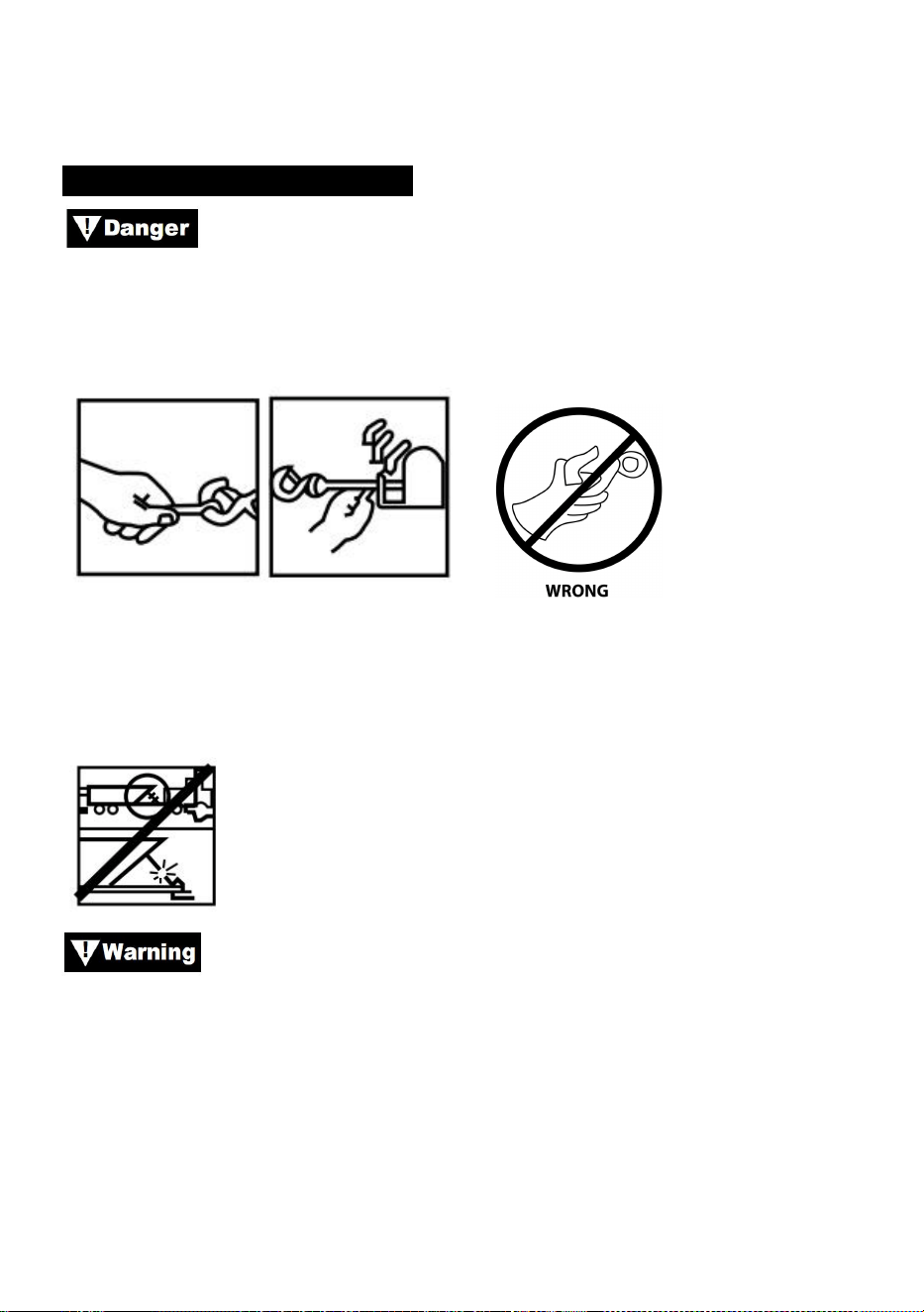
- 22 -
identico consigliato dal produttore.
PREPARAZIONE DEL WEINCH
Indossare guanti di pelle pesanti quando si maneggia il cavo
metallico, anche con i guanti indossati. Quando si maneggia il gancio,
utilizzare sempre il salvamani (vedere Figura 12). Non mettere mai le dita
nel gancio. Mettere le dita nel gancio potrebbe causare lesioni.
Figura 12
1. Quando si ancora il veicolo trainante, azionare il freno di stazionamento
e bloccare o bloccare le ruote. Tenere premuto il freno a pedale del veicolo
e mettere in folle le trasmissioni automatiche e manuali.
Ispezionare l'interruttore e il cablaggio per individuare crepe,
punti schiacciati, fili sfilacciati o connessioni allentate. Un cavo
danneggiato o in cortocircuito potrebbe far funzionare il verricello non
appena viene collegato.
1. Quando si utilizza l'interruttore remoto all'interno di un veicolo, passarlo
sempre attraverso un finestrino per evitare di pizzicare il filo nella portiera.
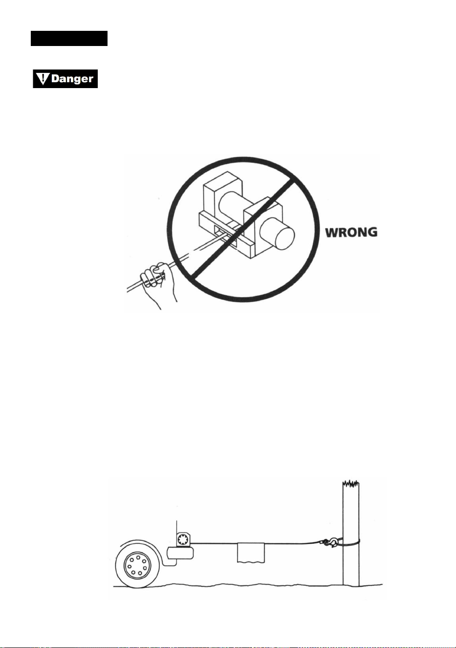
- 23 -
VERRICELLO
Non toccare mai la fune metallica o il gancio mentre sono in
tensione o sotto carico. Anche a riposo, il verricello potrebbe avere la fune
metallica in tensione. Non guidare mai una fune metallica in tensione sul
tamburo con le mani (vedere Fig. 13).
Figura 13
1. Argano con almeno cinque giri di fune metallica attorno al tamburo
dell'argano. Con meno giri, la fune metallica potrebbe staccarsi dal
tamburo sotto carico.
2. Quando si tira un carico, posizionare una coperta, una giacca o un
telone sopra il cavo metallico vicino all'estremità del gancio (vedere Fig.
14). Ciò rallenterà il ritorno di un cavo metallico rotto e aiuterà a prevenire
gravi lesioni. Sollevare il cofano per proteggere il parabrezza.
Figura 14
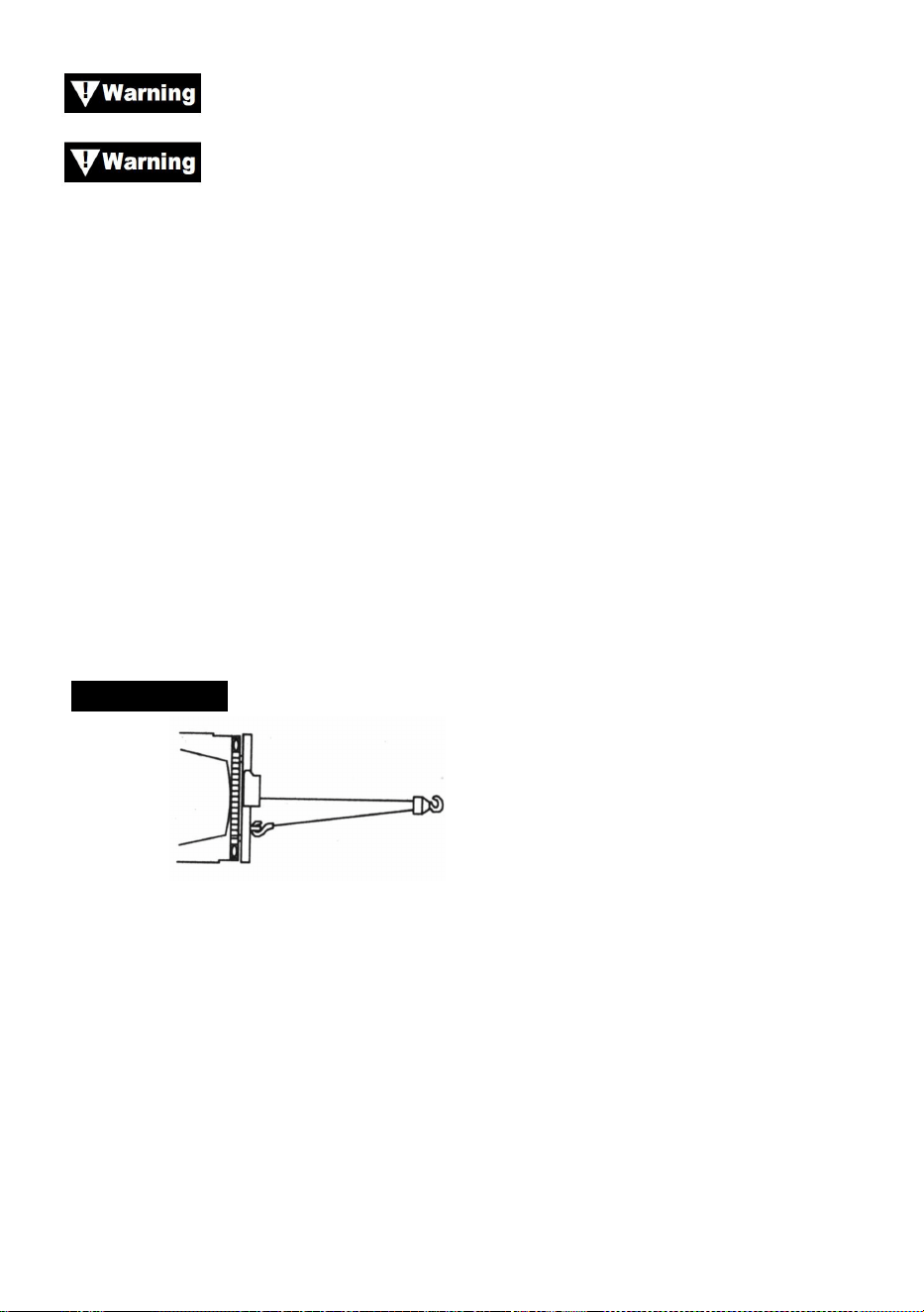
- 24 -
Rispettare la portata nominale del verricello e non superarla.
Quando il carico supera la trazione nominale massima del
verricello, l'interruttore automatico esterno spegnerà automaticamente il
verricello. Per ripristinare l'interruttore automatico, rilasciare il pulsante
dell'interruttore. Notare che il verricello non sarà in grado di riavviarsi
normalmente finché il calore del motore accumulato dalla sollecitazione
eccessiva non si sarà raffreddato.
1. Doppia linea con un blocco puleggia (vedere Fig. 15) per ridurre il
carico sul verricello, sulla fune metallica e sulla batteria. La doppia linea
ridurrà anche la velocità della linea del verricello. Assicurarsi che tutta
l'attrezzatura utilizzata soddisfi la massima capacità di tiro della linea del
verricello. Quando si effettua la doppia linea, i blocchi puleggia devono
essere dimensionati almeno a due volte la capacità di tiro della linea del
verricello.
VERRICELLO
Figura 15
1. Se si installa un gancio di traino per il doppio rivestimento, questo deve
essere fissato al telaio del veicolo.
2. L'installazione di un passacavo sul verricello riduce l'usura della fune
metallica durante i tiri angolari.
3. Tirare il più dritto possibile per ridurre l'accumulo di fune metallica su
un'estremità del tamburo.
4. Durante l'azionamento del verricello, il motore del veicolo deve essere
acceso. Se si esegue un'operazione di azionamento considerevole con il
motore spento, la batteria potrebbe essere troppo scarica per riavviare il

- 25 -
motore.
Utilizzare un blocco di puleggia per evitare di eseguire il
verricello ad angoli acuti. Una stratificazione non uniforme causerà gravi
danni al verricello e alla fune metallica. Se è possibile correggere il
problema fissando il carico, srotolando la fune metallica e riposizionandola
all'estremità opposta del tamburo.
Non disinnestare la frizione sotto carico, se il tuo verricello è
dotato di una frizione a bobina libera, assicurati che non ci sia tensione
sulla fune metallica quando disinnesti la frizione. Prima di sollevare un
carico, assicurati che la frizione sia completamente innestata.
Utilizzare il verricello per spostare il carico. Non tentare di
aiutare il verricello spostando il veicolo. La combinazione del verricello e
del veicolo che tira potrebbe sovraccaricare la fune metallica e il carico
potrebbe rompere il verricello.
Non affidarti mai al verricello per tenere fermo un carico.
Nessuno dei nostri verricelli è progettato per applicazioni di tenuta del
carico e potrebbe srotolarsi o guastarsi a causa di carichi d'urto durante il
trasporto del carico. Il carico deve essere fissato con altri mezzi e il gancio
del verricello staccato dal carico.
SARTIAME
Prenditi il tuo tempo quando organizzi il rigging e includi un
fattore ragionevole per la sicurezza. Un rigging improprio può causare
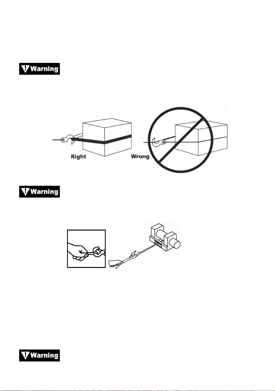
- 26 -
danni al veicolo e all'attrezzatura. Può anche causare lesioni.
10.Non maneggiare mai il cavo metallico o l'attrezzatura mentre un'altra
persona è al comando.
11.
Utilizzare una fettuccia di nylon quando si collega il cavo
metallico a un punto di ancoraggio. Non riattaccare il gancio al cavo
metallico. Ciò potrebbe causare la rottura del cavo metallico.
Figura 16
Utilizzare sempre il salvamani (vedere Fig. 17). Non tenere il
gancio con la mano. Questo è importante non solo quando si riavvolge il
cavo metallico, ma anche quando si rimuove il cavo metallico dal verricello
sotto tensione.
Figura 17
12.Azionare il verricello a intermittenza per eliminare il gioco della fune
metallica. Quando si utilizza un paranco a puleggia, assicurarsi che la fune
metallica scorra correttamente in tutte le pulegge prima di applicare un
carico.
Non reinserire la frizione mentre il verricello è in funzione.
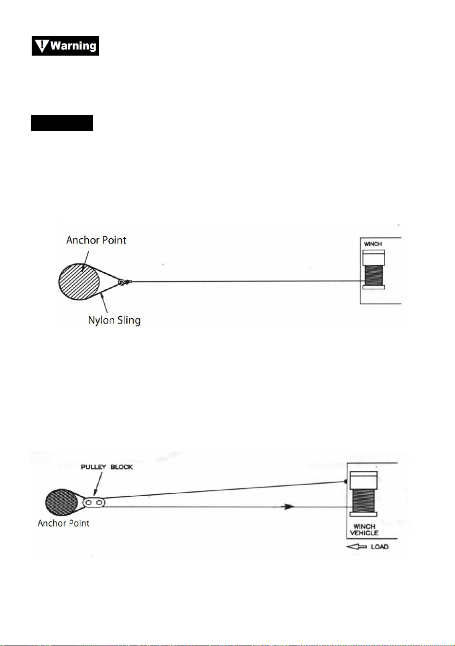
- 27 -
Utilizzare sempre il verricello con una visuale libera
dell'operazione di sollevamento. Non oscurare mai le etichette di
avvertenza e di istruzioni.
SARTIAME
3. La figura 18 illustra l'attrezzatura più comunemente utilizzata. Una
fettuccia di nylon viene utilizzata per proteggere l'albero quando viene
utilizzato come ancoraggio, e il cavo metallico è attaccato per utilizzare la
fettuccia. L'uso di una catena o di un cavo metallico non è raccomandato a
causa dei danni che potrebbe causare all'albero.
Figura 18
19. La figura 19 illustra un metodo di rigging utilizzato per ottenere un
vantaggio meccanico. L'uso di un blocco di puleggia raddoppia quasi la
capacità di trazione della linea. (Si noti che il blocco di puleggia non è
incluso)
Figura 19
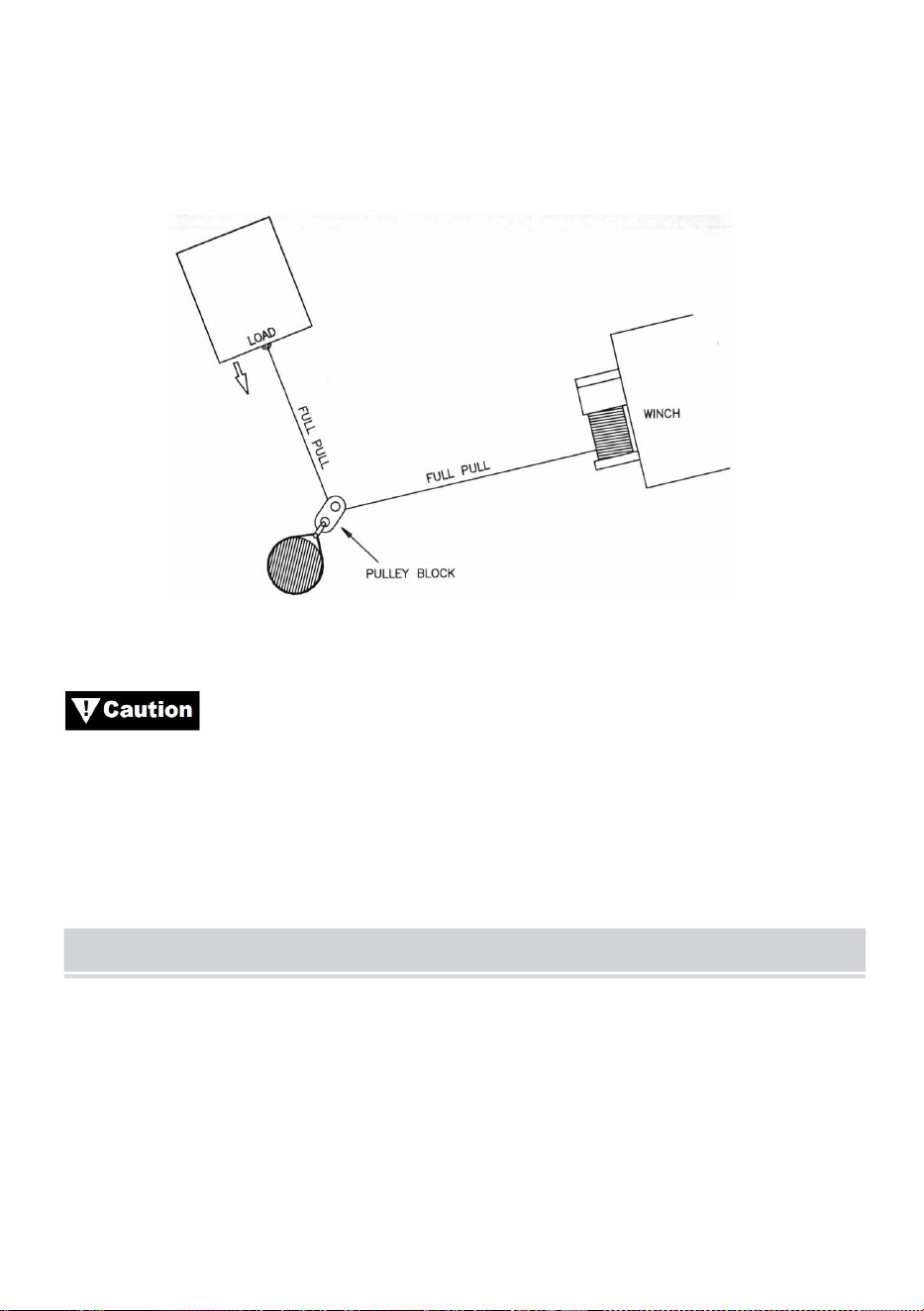
- 28 -
20. La figura 20 illustra l'uso di un blocco di puleggia per cambiare la
direzione della trazione. Il vantaggio meccanico può essere ottenuto
collegando un blocco di puleggia alla fettuccia di nylon con un grillo e
facendo passare la fune metallica fino al punto di ancoraggio.
Figura 20
Attrezzature quali paranchi, ganci, carrucole, cinghie, ecc.
devono essere adeguatamente dimensionate e classificate e devono
essere ispezionate periodicamente per verificare che non vi siano danni
che potrebbero ridurne la resistenza.
MAINTAINNENCE
1) Controllare periodicamente la tenuta dei bulloni di montaggio e dei
collegamenti elettrici. Rimuovere tutto lo sporco o la corrosione e
mantenerli sempre puliti.
2) Non tentare di smontare la scatola del cambio. Le riparazioni devono
essere eseguite dal produttore o da un centro autorizzato.
3) La scatola del cambio è stata lubrificata con grasso al litio ad alta

- 29 -
temperatura ed è sigillata in fabbrica. Non è richiesta alcuna lubrificazione
interna.
TROUBLE SHOOTING
Sintomi
Possibili cause
Azione correttiva
Il motore non funziona o
funziona solo in una
direzione
1. Interruttore non
operativo
2. Cavi rotti o cattiva
connessione
3. Motore danneggiato
1.Sostituire l'interruttore
2. Controllare eventuali
connessioni scadenti
3.Sostituire o riparare il motore
Il motore funziona a una
temperatura
estremamente elevata
1.Lungo periodo di
funzionamento
2. non riuscito o rimosso
sovraccarico
3. Motore danneggiato
1.da basso a freddo
2. Posizionare o riparare il
sovraccarico
3. Posizionare o riparare il
motore
Il motore funziona, ma con
potenza o velocità di linea
insufficienti
1. Batteria scarica
2. Cavo della batteria al
verricello troppo lungo
3. Collegamento scadente
della batteria
4. Terreno povero
5. Motore danneggiato
1. Ricaricare o sostituire la
batteria e controllare il sistema
di ricarica
2. Mantenere il verricello entro
la distanza consentita dai cavi di
collegamento
3. Controllare i terminali della
batteria per la corrosione e
pulirli se necessario
4.Controllare e pulire i
collegamenti
5. Posizionare o riparare il
motore

- 30 -
L'argano funziona
all'indietro
1.fili tor invertiti
2. I fili del prurito sono
invertiti
3. Interruttore della
batteria installato in modo
errato
1. Controllare il cablaggio
2. controllare il cablaggio
3.Controllare i collegamenti
della batteria
Il motore funziona ma il
tamburo non gira
1. Frizione non innestata
1. Innestare la frizione
Coste del verricello
1.Carico eccessivo
1. Ridurre il carico o
raddoppiare la linea
Il motore funziona ma si
ferma
1. Carico
eccessivo/sovraccarico
1. Lasciare raffreddare


Técnico Soporte y certificado de garantía electrónica www.vevor.com/support
CABRESTANTE ELÉCTRICO
MODELO: P2000-1/P3000-1C/P4000-1D/P4000-1W
We continue to be committed to provide you tools with competitive price.
"Save Half", "Half Price" or any other similar expressions used by us only represents an
estimate of savings you might benefit from buying certain tools with us compared to the major
top brands and does not necessarily mean to cover all categories of tools offered by us. You
are kindly reminded to verify carefully when you are placing an order with us if you are
actually saving half in comparison with the top major brands.


- 1 -
MODELO: P2000-1/P3000-1C/P4000-1D/P4000-1W
Have product questions? Need technical support? Please feel free to
contact us:
Technical Support and E-Warranty Certificate
www.vevor.com/support
NEED HELP? CONTACT US!
This is the original instruction, please read all manual instructions
carefully before operating. VEVOR reserves a clear interpretation of our
user manual. The appearance of the product shall be subject to the
product you received. Please forgive us that we won't inform you again if
there are any technology or software updates on our product.
ELECTRIC WINCH
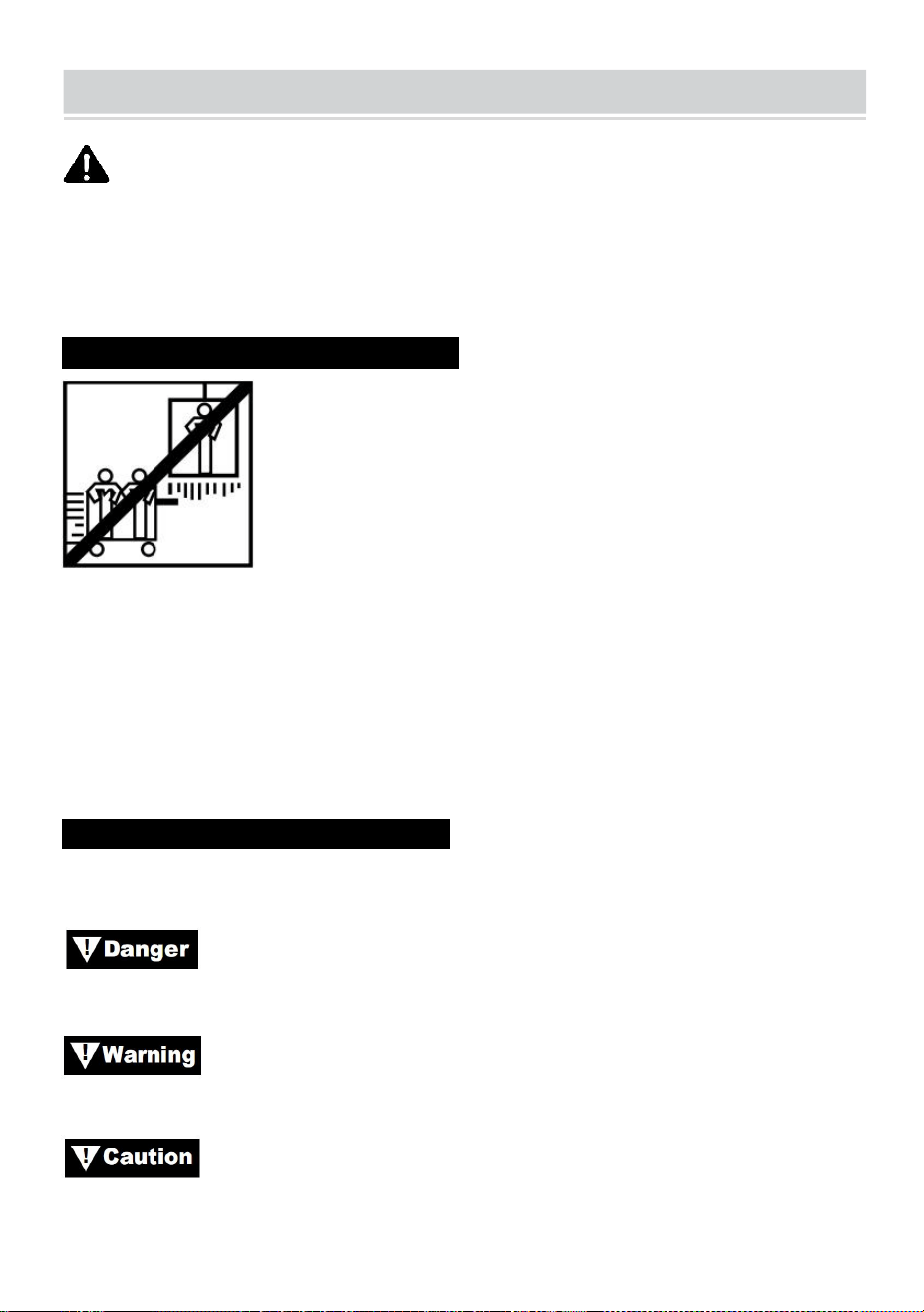
- 2 -
SAFE INSTRUCTIONS
ADVERTENCIA: Lea atentamente y comprenda todas las
INSTRUCCIONES DE MONTAJE Y FUNCIONAMIENTO antes de utilizar
el producto. No seguir las reglas de seguridad y otras precauciones
básicas de seguridad puede provocar lesiones personales graves.
INFORMACIÓN DE LA SOLICITUD N
Este cabrestante está diseñado para mover una carga a nivel del suelo o
por una pendiente. No está diseñado ni destinado para elevación.
Este cabrestante no debe utilizarse para levantar o mover personas.
Este cabrestante es para uso intermitente debido a las características de
acumulación de calor de varios componentes. Si el extremo del motor se
vuelve incómodamente caliente al tacto, deje de usar el cabrestante y deje
que el motor se enfríe.
PRECAUCIONES DE SEGURIDAD
A lo largo de este manual encontrará anotaciones con los siguientes
encabezados:
:Indica una situación de peligro inminente que, si no se evita,
provocará la muerte o lesiones graves.
:Indica una situación potencialmente peligrosa que, si no se
evita, podría provocar la muerte o lesiones graves.
: Indica una situación potencialmente peligrosa que, si no se
evita, puede provocar lesiones leves o moderadas. Esta notación también
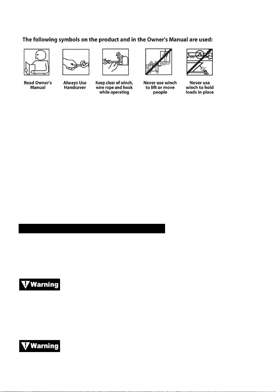
- 3 -
se utiliza para alertar sobre prácticas inseguras.
Nota: Indica información adicional en los procedimientos de
instalación y operación de su cabrestante.
Nota : el cabrestante está diseñado principalmente para aplicaciones
intermitentes. Este cabrestante no está diseñado para usarse en
aplicaciones industriales o de elevación.
Utilice siempre un protector de manos en el gancho.
Manténgase alejado del cabrestante, del cable de acero y del gancho
durante la operación.
Nunca utilice el cabrestante para levantar o mover personas.
Nunca utilice un cabrestante para mantener cargas en su lugar.
INFORMACIÓN GENERAL DE SEGURIDAD
Su cabrestante es una máquina muy potente. Si se utiliza de forma
insegura o inadecuada, Podría provocar daños a la propiedad o lesiones
personales.
La responsabilidad de instalar y operar el cabrestante de
manera segura y de evitar lesiones personales y daños a la propiedad
recae en última instancia sobre usted, el operador. No hay sustituto para el
uso del buen juicio y la precaución al operar un cabrestante.
El cable de acero puede romperse antes de que el
cabrestante se detenga.
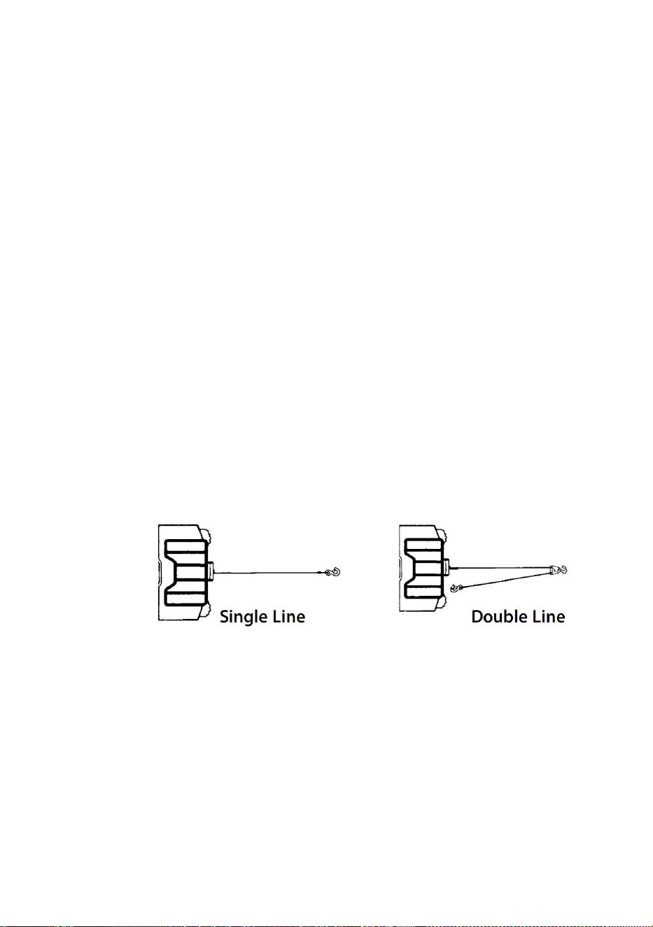
- 4 -
Para cargas pesadas, utilice un bloque de polea para reducir la carga
sobre la
Cable de acero.
117.La capacidad máxima de carga de trabajo se encuentra en la capa de
cable de acero más cercana al tambor. NO SOBRECARGUE. NO
INTENTE TIRAR DE FORMA PROLONGADA CON CARGAS
PESADAS. Las sobrecargas pueden dañar el cabrestante o el cable
de acero y crear condiciones de funcionamiento inseguras. PARA
CARGAS SUPERIORES A LA MITAD DE LA CAPACIDAD NOMINAL,
RECOMENDAMOS EL USO DEL BLOQUE DE POLEA OPCIONAL
PARA DOBLAR EL CABLE DE ACERO (FIGURA 1). Esto reduce la
carga en el cabrestante y la tensión en el cable de acero
aproximadamente en un 50 %. Conecte el gancho a la parte que
soporta la carga. El motor del vehículo debe estar en funcionamiento
durante la operación del cabrestante. Si se realiza un trabajo
considerable con el motor apagado, la batería puede estar demasiado
débil para volver a arrancar el motor.
Figura 1.
118.DESPUÉS DE LEER Y COMPRENDER ESTE MANUAL, APRENDA A
USAR SU CABRESTANTE. Después de instalar el cabrestante,
practique su uso para familiarizarse con él cuando surja la necesidad.
119.NO “mueva” su vehículo para ayudar al cabrestante a tirar de la carga.
La combinación del cabrestante y el tirón del vehículo juntos podría
sobrecargar el cable de acero y el cabrestante.
120. MANTÉNGASE SIEMPRE ALEJADO DE CABLES DE ACERO,
GANCHOS Y CABRESTANTES. EN EL IMPROBABLE CASO DE
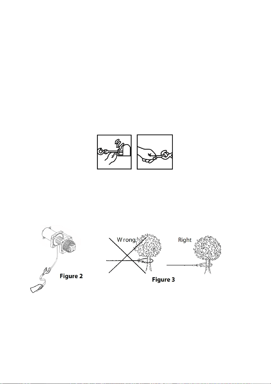
- 5 -
QUE FALLE CUALQUIER COMPONENTE, ES MEJOR ESTAR
FUERA DE PELIGRO.
121. Inspeccione los cables y el equipo con frecuencia. Un cable
desgastado con hebras rotas debe reemplazarse de inmediato.
122. Utilice guantes de cuero gruesos al manipular cables de acero.
No permita que el cable se deslice entre sus manos.
123. Nunca utilice el cabrestante con menos de 5 vueltas de cable de
acero alrededor del tambor del cabrestante, ya que el sujetador del
extremo del cable de acero puede NO soportar la carga completa.
124. Nunca introduzca el dedo en el anzuelo. Si queda atrapado en él,
podría perderlo .
125. UTILICE SIEMPRE EL PROTECTOR DE MANO al guiar el cable
de acero hacia adentro o hacia afuera. (Ver Figura 2).
126. NUNCA ENGANCHE EL CABLE DE ACERO SOBRE SÍ MISMO,
ya que podría dañarlo. Utilice una eslinga de nailon (Figura 3).
127. Es una buena idea colocar una manta o una cubierta pesada
sobre el cable de acero cerca del extremo del gancho cuando se tira
de cargas pesadas (Figura 4). Si se produce una falla en el cable de
acero, la tela actuará como amortiguador y ayudará a evitar que el
cable se mueva.
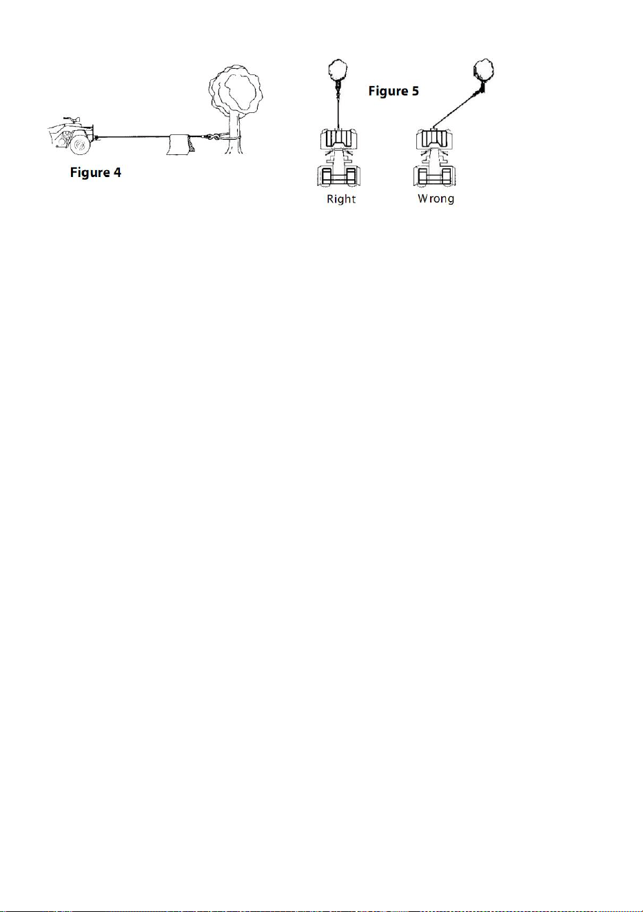
- 6 -
128. EVITE TIRONES CONTINUOS DESDE ÁNGULOS EXTREMOS
ya que esto provocará que el cable de acero se amontone en un
extremo del tambor. Esto puede atascar el cable de acero en el
cabrestante, causando daños al cable o al cabrestante.
129. NUNCA OCULTE LAS ETIQUETAS DE INSTRUCCIONES DE
ADVERTENCIA.
130. Opere siempre el cabrestante con una vista sin obstáculos de la
operación de cabrestante.
131. Los equipos tales como aparejos, ganchos, poleas, correas, etc.
deben dimensionarse de acuerdo a la tarea de elevación y deben
inspeccionarse periódicamente para detectar daños que puedan
reducir su resistencia.
132. NUNCA SUELTE EL EMBRAGUE DE CARRETE LIBRE
CUANDO HAYA CARGA EN EL CABRESTANTE.
133. NUNCA TRABAJE EN O ALREDEDOR DEL TAMBOR DEL
CABRESTANTE CUANDO EL MISMO ESTÉ BAJO CARGA.
134. NO OPERE EL CABRESTANTE BAJO LA INFLUENCIA DE
DROGAS, ALCOHOL O MEDICAMENTOS.
135. SIEMPRE DESCONECTE LOS CABLES DE ALIMENTACIÓN
DEL CABRESTANTE A LA BATERÍA ANTES DE TRABAJAR EN O
ALREDEDOR DEL TAMBOR DEL CABRESTANTE para que el
cabrestante no se pueda encender accidentalmente.
136. Al mover una carga, tense lentamente el cable de acero hasta que
quede tenso. Deténgase y vuelva a verificar todas las conexiones del
cabrestante. Asegúrese de que el gancho esté correctamente
colocado. Si se utiliza una eslinga de nailon, verifique la sujeción a la
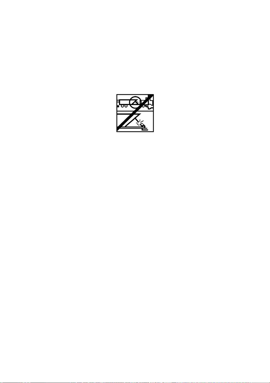
- 7 -
carga.
137. Cuando utilice el cabrestante para mover una carga, coloque la
transmisión del vehículo en punto muerto, aplique el freno del vehículo
y calce todas las ruedas.
138. NO UTILICE EL CABRESTANTE PARA MANTENER LAS
CARGAS EN SU LUGAR. Utilice otros medios para asegurar las
cargas, como correas de amarre.
139. UTILICE SOLO INTERRUPTORES, CONTROLES REMOTOS Y
ACCESORIOS APROBADOS POR LA FÁBRICA. El uso de
componentes no aprobados por la fábrica puede provocar lesiones o
daños a la propiedad.
140. NO MECANICE NI SUELDE NINGUNA PARTE DEL
CABRESTANTE. Tales alteraciones pueden debilitar la integridad
estructural del cabrestante.
141. NO CONECTE EL CABRESTANTE A LA CORRIENTE
ELÉCTRICA DE 110 V CA NI A LA RED ELÉCTRICA DE 220 V, YA
QUE PODRÍA QUEMARSE O PRODUCIRSE UNA DESCARGA
FATAL.
142. Nunca permita que se apliquen cargas de impacto al cabrestante
o al cable de acero.
143. Tenga cuidado al subir o bajar una carga por una rampa o
pendiente. Mantenga a las personas, las mascotas y la propiedad
alejadas del camino de la carga.
144. El conjunto del interruptor debe mantenerse libre de suciedad y
humedad para garantizar un funcionamiento seguro.
145. Para evitar el uso no autorizado del cabrestante, retire el control
colgante y guárdelo en un área limpia y seca, como la guantera.

- 8 -
PRODUCT SPECIFICATION
Contenido del paquete
P2000-1
P3000-1C
P4000-1D
P4000-1W
Voltaje
12 V CC
12 V CC
12 V CC
12 V CC
Potencia
nominal
0,95 CV
1,3 CV
2,2 CV
2,2 CV
Relación de
transmisión
153
:
1
153
:
1
128,2:1
128,2:1
Longitud del
cable
1,8 millones
1,8 millones
1,8 millones
1,8 millones
Soga
Acero ,
5/32 pulgadas
x 39 pies
Acero ,
3/16
pulgadas x
39 pies
Acero ,
1/4 pulgada * 39
pies
Sintético ,
1/4 pulgada * 39
pies
Clasificación
IP
55
55
55
55
P2000-1
P3000-1C
P4000-1D
P4000-1W
Model
SPEC.
Model
Parts

- 9 -
PRODUCT ASSEMBLY INSTRUCTIONS
MONTAJE DEL CABRESTANTE
KITS DE MONTAJE
Cabrestante
eléctrico
1
1
1
1
Caja de
control
×
1
1
1
Control
remoto
inalámbrico
×
1
1
1
Manejar el
controlador
1
1
1
1
Guía de
rodillos
1
1
1
1
Soporte de
montaje
1
1
1
1
Gancho de
horquilla
1
1
1
1
Banda roja
1
1
1
1
Juego de
tornillos
1
1
1
1
Manual
1
1
1
1
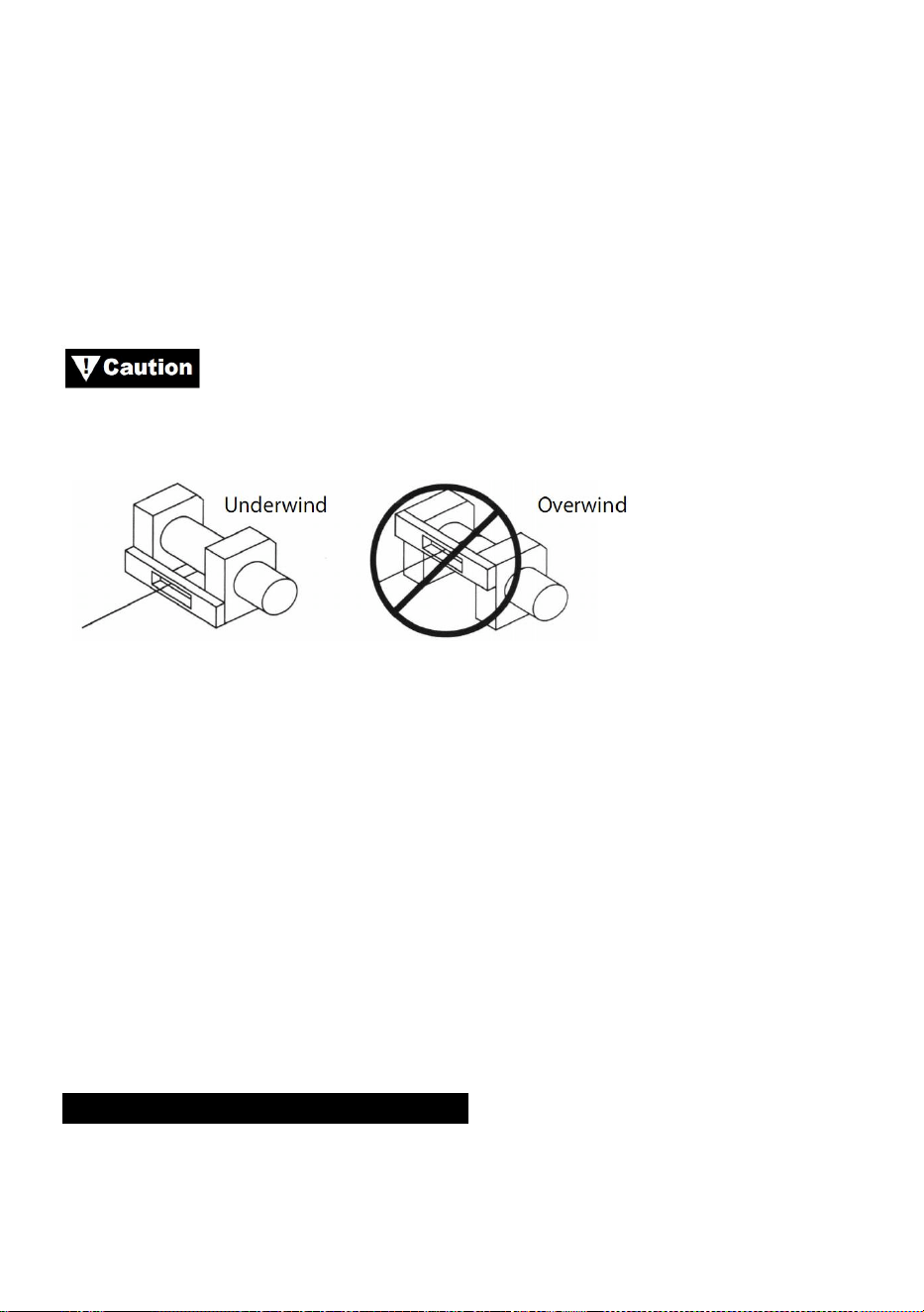
- 10 -
EL FABRICANTE RECOMIENDA EL USO DE UN KIT DE MONTAJE
PARA UN MONTAJE SEGURO EN SU VEHÍCULO. Los kits de montaje de
cabrestante para vehículos todo terreno normalmente se incluyen en el
paquete del cabrestante. Si decide no comprar un kit de montaje, su
cabrestante debe estar fijado a una ubicación de montaje segura y plana.
Tenga en cuenta que es posible que su cabrestante no pueda operarse de
manera segura sin algunos equipos incluidos en el kit.
Este cabrestante debe montarse con el cable de acero en
la dirección de enrollado hacia abajo (Figura 6).
Figura 6
Nota: Es posible y no es raro ni desaconsejado montar el cabrestante en
actitudes distintas a las que se muestran en este manual de instalación.
Si bien la posición de montaje es a su discreción, recuerde siempre que el
cabrestante debe operarse con el cable de acero en una orientación
inferior al tambor del cable de acero (Figura 1). El cabrestante está
diseñado para ENCENDER Y APAGAR el cable en una dirección. No
intente invertir el funcionamiento del cabrestante.
INSTALACIÓN DEL CABRESTANTE
Nota : Al instalar un cabrestante, su instalación puede variar levemente de
las instrucciones y diagramas que siguen, dependiendo de su vehículo,
cabrestante, kit de montaje o soporte estructural.

- 11 -
Antes de comenzar la instalación del cabrestante,
desconecte los cables de tierra del vehículo y los cables positivos de
la batería.
REQUISITOS ELÉCTRICOS MÍNIMOS
Asegúrese de seleccionar la batería o la fuente de alimentación
adecuadas para manejar este cabrestante. Si el cabrestante se utiliza de
forma intensiva, se recomienda una batería auxiliar y un alternador de alta
resistencia.
PROCEDIMIENTO DE INSTALACIÓN:
PASO (1)
Instale el kit de montaje o prepare una ubicación de montaje plana y
segura para el cabrestante a fin de asegurarse de que el motor, el tambor
y la caja de engranajes estén alineados correctamente. Siga atentamente
las instrucciones incluidas con el kit de montaje.
Asegúrese de que el soporte estructural sea lo
suficientemente fuerte para soportar la capacidad nominal del cabrestante.
Nota: Si no tienes un kit de montaje, tendrás que hacer agujeros en el
soporte estructural. Asegúrate de que el soporte estructural tenga un
grosor de al menos 3/16” (5 mm).
Si se requieren pernos, tuercas, arandelas y otros accesorios
de longitud diferente para su instalación, utilice siempre accesorios que
tengan un grado de resistencia igual o superior al del accesorio
suministrado.
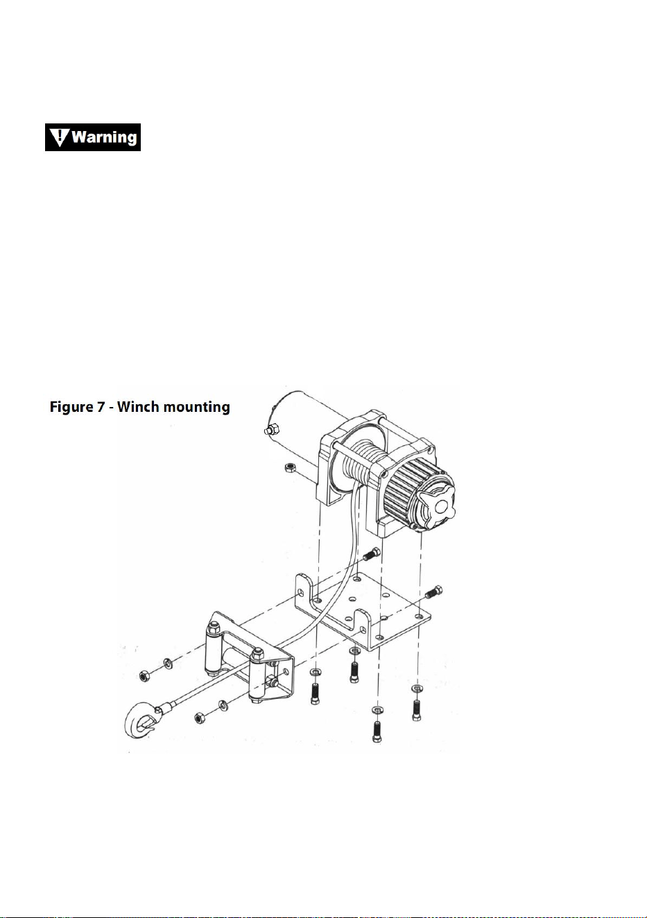
- 12 -
Paso ( 2 )
Coloque el cabrestante sobre los orificios del kit de montaje o del soporte
estructural.
Al colocar el cabrestante, asegúrese de que el cable de
acero se enrolle en el sentido de giro correcto en el tambor. Si no se opera
el cabrestante en la dirección correcta, el freno del cabrestante (si está
equipado) puede funcionar incorrectamente y/o provocar que el
cabrestante falle.
Paso (3)
Asegure el cabrestante (figura 7) al kit de montaje o al soporte estructural
usando pernos, arandelas de seguridad y tuercas cuadradas
suministradas con el cabrestante.
Paso (4)
Asegure la guía del rodillo (Figura 7) a la placa de montaje o al soporte de
la estructura usando los herrajes suministrados o usando dos (2) pernos

- 13 -
de acero de resistencia a la tracción M8x 20L de grado 8.8.
Asegúrese de que tanto la placa de montaje como los
herrajes del cabrestante estén correctamente apretados.
Ninguna parte del vehículo (placas protectoras, cableado,
luces auxiliares, neumáticos, etc.) debe impedir el funcionamiento del
cabrestante. Al montarlo, compruebe que todas las piezas del vehículo y
del cabrestante funcionan sin problemas. Asegúrese de que la ubicación
de montaje del cabrestante no reduzca significativamente la distancia al
suelo.
MONTAJE DE LA CAJA DE SOLENOIDES
13. La caja de solenoides desconecta el cabrestante de la batería cuando
el vehículo está apagado.
14. La caja de solenoides debe montarse cerca de la batería y en un lugar
que esté lo más limpio y seco posible.
15. Asegúrese de que la ubicación de la caja de solenoides seleccionada
proporcione suficiente espacio libre de todas las estructuras metálicas,
como los tubos del bastidor.
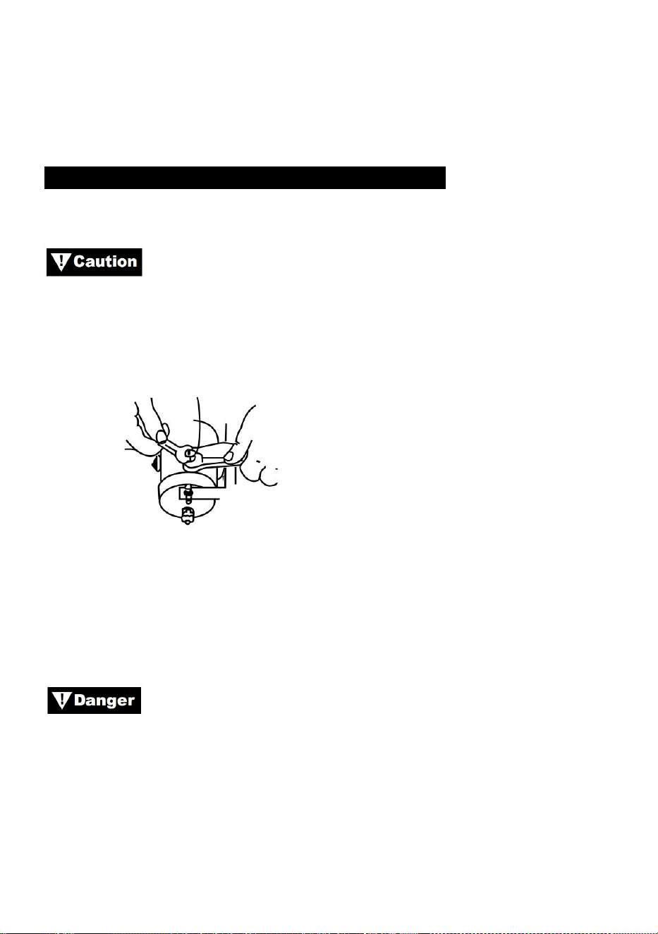
- 14 -
INSTALACIÓN DEL INTERRUPTOR DE PALANCA
APLICACIONES: SERIE ATV
Al conectar los cables a los terminales del motor o del
eslenoide, sujete la tuerca interior con una llave mientras aprieta la tuerca
exterior con una segunda llave. No permita que los terminales giren en sus
alojamientos. La rotación puede provocar la rotura interna de los cables o
la desalineación de las piezas (Figura 9).
Figura 9: Ajuste correcto de los terminales
Paso (1)
Verifique que los cables de tierra del vehículo y positivos de la batería
estén desconectados antes de realizar cualquier trabajo eléctrico.
NO INTENTE INSTALAR EL CABLEADO CUANDO LA
BATERÍA ESTÉ CONECTADA. Las baterías de los automóviles contienen
gases inflamables y explosivos. Use protección para los ojos durante la
instalación y quítese todas las joyas de metal. No se incline sobre la
batería mientras realiza las conexiones.
Paso (2)
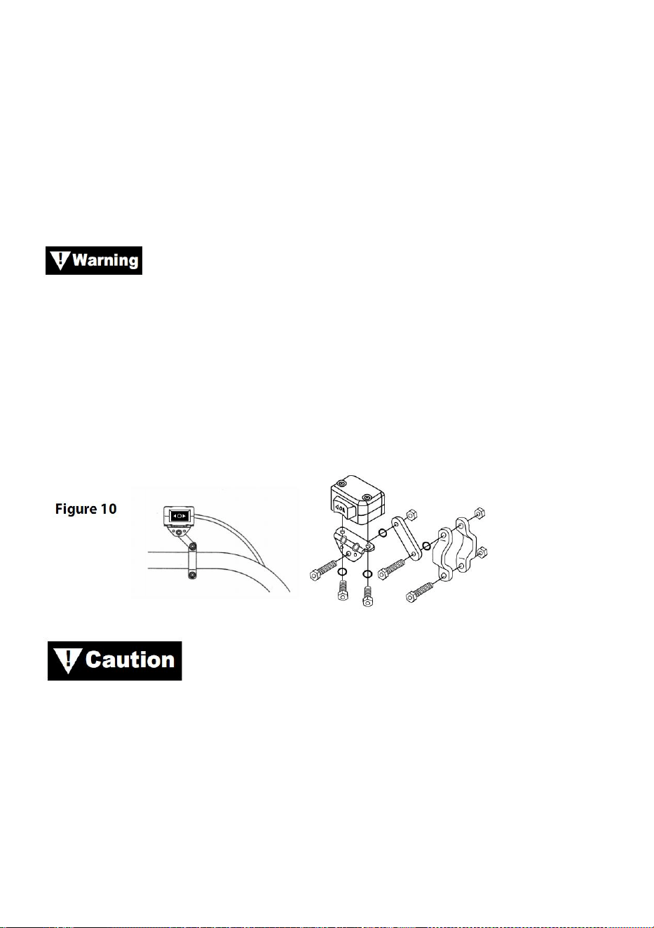
- 15 -
Pase el mazo de cables, fijándolo a los puntos duros del vehículo con
bridas.
Nota: Al colocar los cables, los terminales correspondientes deben
ubicarse cerca de la batería, el punto de montaje del interruptor y el
cabrestante. Los requisitos de instalación variarán según el vehículo y el
cabrestante. Asegúrese de que los cables sean lo suficientemente largos
para llegar a la batería, el punto de montaje del interruptor y el
cabrestante.
Asegúrese de que el mazo de cables no interfiera ni entre en
contacto con ninguna pieza caliente o en movimiento del motor, la
suspensión, la dirección, el frenado o el escape.
Paso(3)
Utilice las abrazaderas, el soporte y los herrajes suministrados para
montar el interruptor basculante en una ubicación conveniente. Consulte la
Figura 10.
UTILICE SIEMPRE EL SOPORTE DE MONTAJE DEL
INTERRUPTOR DE PALANCA, LOS TORNILLOS Y LAS TUERCAS DE
SEGURIDAD PROVISTOS. Las longitudes de los tornillos están
dimensionadas para una penetración correcta en la caja del interruptor.
Una penetración excesiva puede provocar cortocircuitos que podrían
provocar un sobrecalentamiento del cable.
Paso (4)
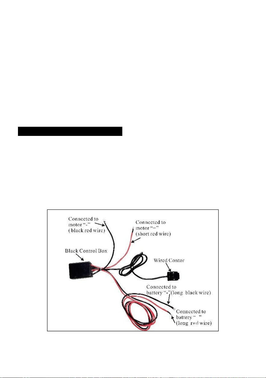
- 16 -
Se recomienda que el interruptor se instale en el manillar izquierdo.
INSTALACIÓN DEL CABLEADO
Paso (1)
Pase los cables cortos codificados por color rojo y negro hasta el
motor.
Pase los cables largos codificados por color rojo y negro hacia la
batería.

- 17 -

- 18 -
Paso( 2 )
Compruebe que todo el cableado esté libre de bordes afilados y
puntos de pinzamiento.
Asegure el cableado suelto con bridas o cinta aisladora.
Nunca deje el interruptor enchufado cuando el cabrestante no esté en
uso.
PRODUCT INSTRUCTIONS
Antes de probar el funcionamiento del cabrestante,
asegúrese de desenrollar aproximadamente dos pies de cable de acero.
PRUEBA DE CONDUCCIÓN
9. Verifique nuevamente que todo el cableado sea correcto y que no haya
terminales expuestos que puedan provocar un cortocircuito con el
bastidor del vehículo.
10. Gire la llave de encendido a la posición ON. Verifique que el
cabrestante funcione correctamente.
FUNCIONAMIENTO DE BOBINA LIBRE
Tire y gire la perilla del embrague a la posición “Libre”. Si hay una carga en
el cable de acero, la perilla del embrague puede no salir fácilmente. NO
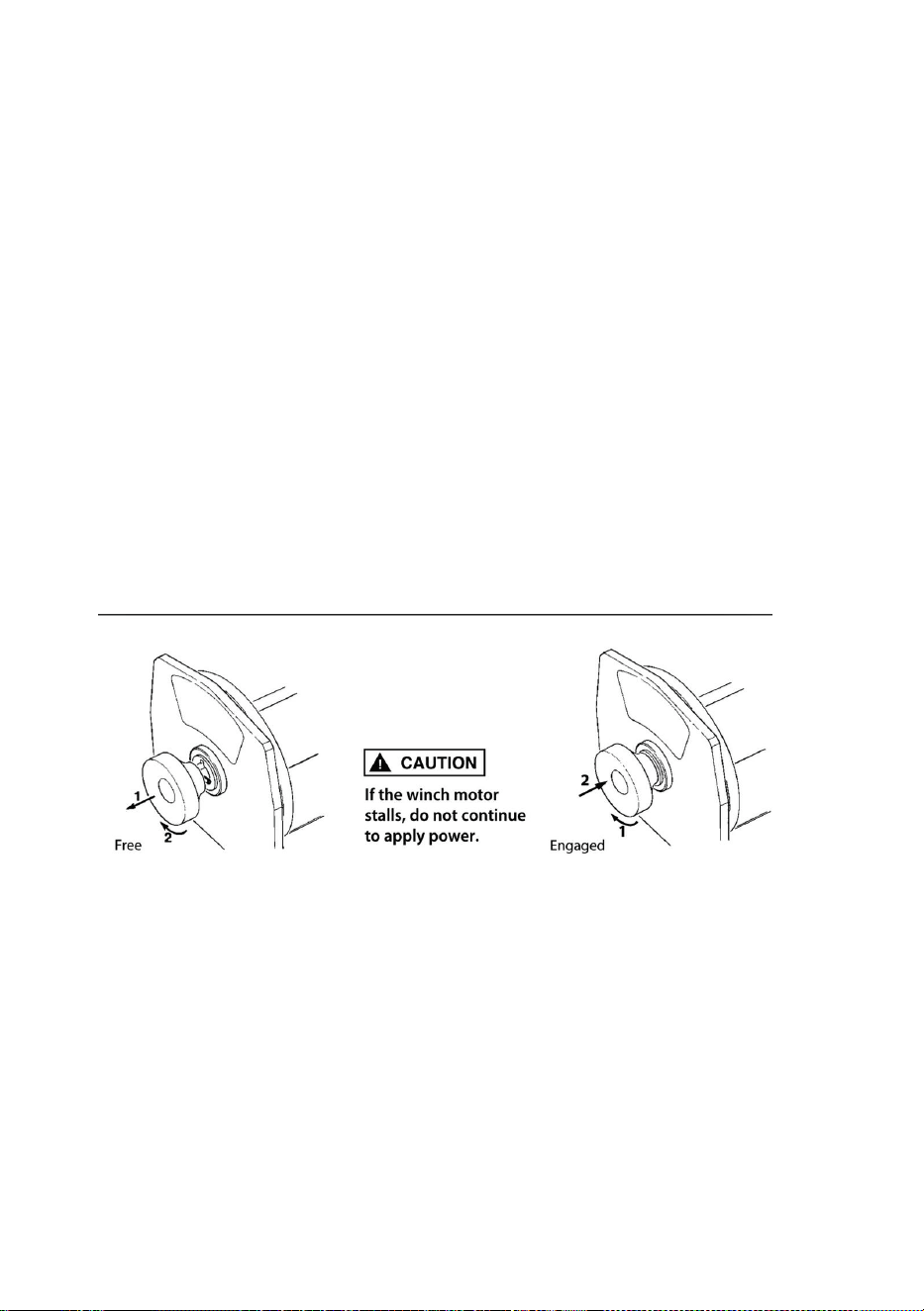
- 19 -
FUERCE LA PERILLA DEL EMBRAGUE. Libere la tensión del embrague
tirando ligeramente del cable de acero. Suelte el embrague y saque el
cable de acero y fíjelo al anclaje o la carga. Verifique que queden al menos
cinco vueltas de cable de acero en el tambor. Vuelva a enganchar el
tambor devolviendo la perilla del embrague a la posición “Enganchado”.
Active el cabrestante en Cable Out momentáneamente para verificar la
dirección de rotación del tambor. Si el tambor gira en la dirección
incorrecta, vuelva a verificar el cableado.
Precaución: Gire la perilla del embrague de acuerdo con las flechas y
las instrucciones para activar o desactivar los engranajes del
cabrestante.
Precaución: El embrague debe estar completamente acoplado antes
de accionar el cabrestante. Nunca accione la perilla del embrague
mientras el tambor esté girando.
COMPROMETIDO: CARRETERA LIBRE:
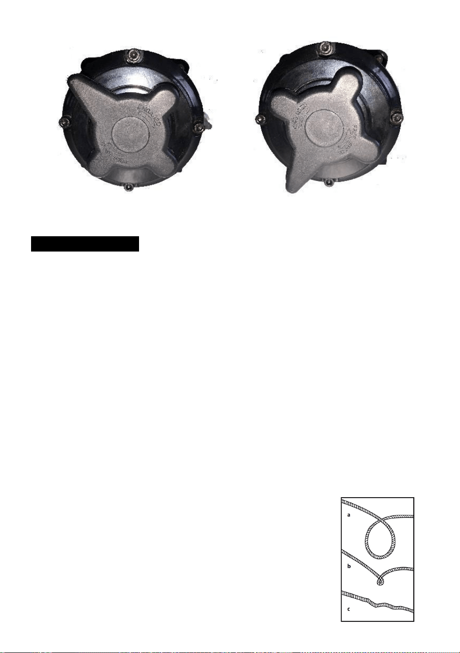
- 20 -
CABLE DE ACERO
21. La vida útil del cable de acero está directamente relacionada con el
cuidado que recibe. El cable de acero de un cabrestante nuevo y
cualquier cable de repuesto deben volver a enrollarse bajo una carga
mínima de 100 libras antes de usar el cabrestante. Si no se hace esto,
el cable de acero se dañará. Inspeccione el cable de acero antes de
usarlo. Las áreas aplastadas, pellizcadas, deshilachadas o enroscadas
reducen gravemente la capacidad de carga. Reemplace el cable de
acero dañado.
22. Evite las torceduras antes de que ocurran.
(m)Este es el comienzo de una torcedura. En este momento, el cable de
acero debe estar enderezado.
(n) Se tiró del cable de acero y el lazo se ha soltado.
apretado hasta una torcedura. El cable de acero ahora
está permanentemente
dañado y no debe utilizarse.
(o) El resultado del enroscamiento es que cada hebra
tira

- 21 -
una cantidad diferente que provoca que las hebras debajo
Mayor tensión para romper y reducir la carga.
Capacidad del cable de acero.
23. Cuando sea necesario volver a enrollar el cable de acero sin carga
después de usarlo, sostenga el cable del interruptor remoto en una
mano y el cable de acero en la otra. Comience desde la distancia más
lejana del vehículo que permita el interruptor remoto, active el
interruptor, introduzca varios pies de cable y suelte el interruptor.
Repita el proceso. Siempre suelte el interruptor antes de que su mano
llegue a menos de cuatro pies de la guía (si está instalada).
24. Asegúrese de que el cable de acero esté distribuido de manera
uniforme y firme en el tambor. Un tambor enrollado de manera floja
permite que el cable de acero se deslice hacia abajo entre las capas
de cable de acero del tambor y se atasque.
25. No es aconsejable engrasar o aceitar el cable de acero debido a la
contaminación por suciedad que reducirá la vida útil del cable de
acero.
SUSTITUYA EL CABLE DE ACERO
21. Si el cable de acero se ha desgastado o empieza a mostrar signos de
rotura de hebras, se debe sustituir antes de volver a utilizarlo. Para ello,
extraiga el cable defectuoso desenrollándolo libremente. Retire el
perno del tambor y suelte el cable.
22. Inserte el extremo de la cuerda nueva y asegure el perno firmemente.
23. Enganche el embrague y vuelva a enrollar la cuerda nueva en el
tambor, manteniendo la tensión en la cuerda mientras se enrolla.
Asegúrese de que la cuerda se esté enrollando nuevamente en la
posición de bobinado inferior.
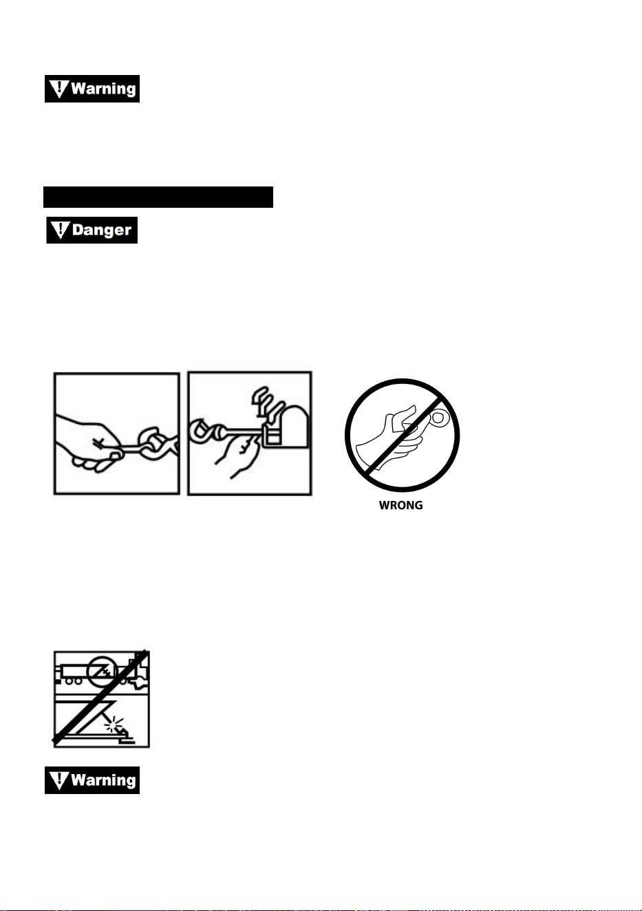
- 22 -
Reemplace el cable de acero únicamente con la pieza de
repuesto idéntica recomendada por el fabricante.
PREPARANDO LA CERVEZA
Utilice guantes de cuero gruesos al manipular cables de
acero, incluso con guantes puestos. Al manipular el gancho, utilice
siempre un protector de manos (consulte la Figura 12). Nunca introduzca
los dedos en el gancho. Si introduce los dedos en el gancho, podría sufrir
lesiones.
Figura 12
1. Al anclar el vehículo que remolca, ponga el freno de estacionamiento y
bloquee o calce las ruedas. Mantenga presionado el freno de pie del
vehículo y coloque las transmisiones automática y manual en punto
muerto.
Inspeccione el interruptor y el cableado para detectar grietas,
puntos pinchados, cables desgastados o conexiones sueltas. Un cable
dañado o en cortocircuito podría hacer que el cabrestante funcione apenas
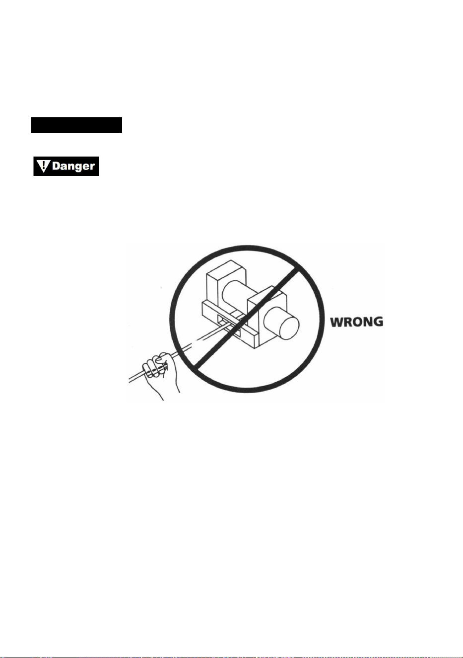
- 23 -
se lo enchufa.
1. Cuando utilice el interruptor remoto dentro de un vehículo, páselo
siempre a través de una ventana para evitar pellizcar el cable en la puerta.
CABRESTANTE
Nunca toque el cable de acero ni el gancho mientras estén
tensados o bajo carga. Incluso en reposo, el cabrestante puede tener el
cable de acero tensado. Nunca guíe un cable de acero tensado hacia el
tambor con las manos (consulte la figura 13).
Figura 13
1. Coloque al menos cinco vueltas de cable de acero alrededor del tambor
del cabrestante. Con menos vueltas, el cable de acero podría soltarse del
tambor bajo carga.
2. Al tirar de una carga, coloque una manta, una chaqueta o una lona
sobre el cable de acero cerca del extremo del gancho (consulte la Figura
14). Esto hará que el cable de acero roto se recupere más lentamente y
ayudará a evitar lesiones graves. Levante el capó para proteger el
parabrisas.
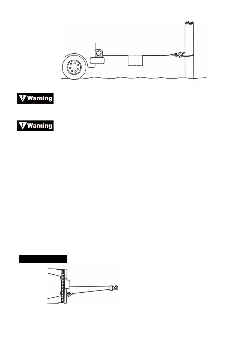
- 24 -
Figura 14
Tenga en cuenta la capacidad nominal del cabrestante y no la
exceda.
Cuando la carga excede la capacidad máxima de tracción del
cabrestante, el disyuntor externo apagará automáticamente el cabrestante.
Para restablecer el disyuntor, suelte el botón del interruptor. Tenga en
cuenta que el cabrestante no podrá reiniciarse normalmente hasta que se
enfríe el calor del motor acumulado por el exceso de tensión.
1. Utilice una polea doble (consulte la Fig. 15) para reducir la carga en el
cabrestante, el cable de acero y la batería. La doble línea también
reducirá la velocidad de la línea del cabrestante. Asegúrese de que todo
el equipo utilizado cumpla con la capacidad máxima de tracción de la
línea del cabrestante. Cuando utilice una doble línea, las poleas deben
tener una capacidad nominal de al menos dos veces la capacidad de
tracción de la línea del cabrestante.
CABRESTANTE
Figura 15
1. Si instala un gancho de remolque para revestimiento doble, debe fijarse

- 25 -
al bastidor del vehículo.
2. Equipar el cabrestante con un guía-cables reducirá el desgaste del
cable de acero durante los tirones en ángulo.
3. Tire lo más recto posible para reducir la acumulación de cable de acero
en un extremo del tambor.
4. El motor del vehículo debe estar en funcionamiento durante la
operación del cabrestante. Si se realiza un trabajo considerable con el
motor apagado, la batería puede estar demasiado débil para reiniciar el
motor.
Utilice un bloque de polea para evitar que el cabrestante se
mueva en ángulos pronunciados. Una disposición desigual de las capas
puede causar daños graves al cabrestante y al cable de acero. Esto se
puede corregir asegurando la carga, desenrollando el cable de acero y
volviéndolo a colocar en el extremo opuesto del tambor.
No desacople el embrague bajo carga. Si su cabrestante está
equipado con un embrague de carrete libre, asegúrese de que no haya
tensión en el cable de acero cuando desacople el embrague. Antes de
levantar una carga con cabrestante, asegúrese de que el embrague esté
completamente acoplado.
Utilice el cabrestante para mover la carga. No intente ayudar
al cabrestante moviendo el vehículo. La combinación del cabrestante y el
tirón del vehículo podría sobrecargar el cable de acero y la carga podría
romper el cabrestante.
Nunca confíe en el cabrestante para mantener una carga en
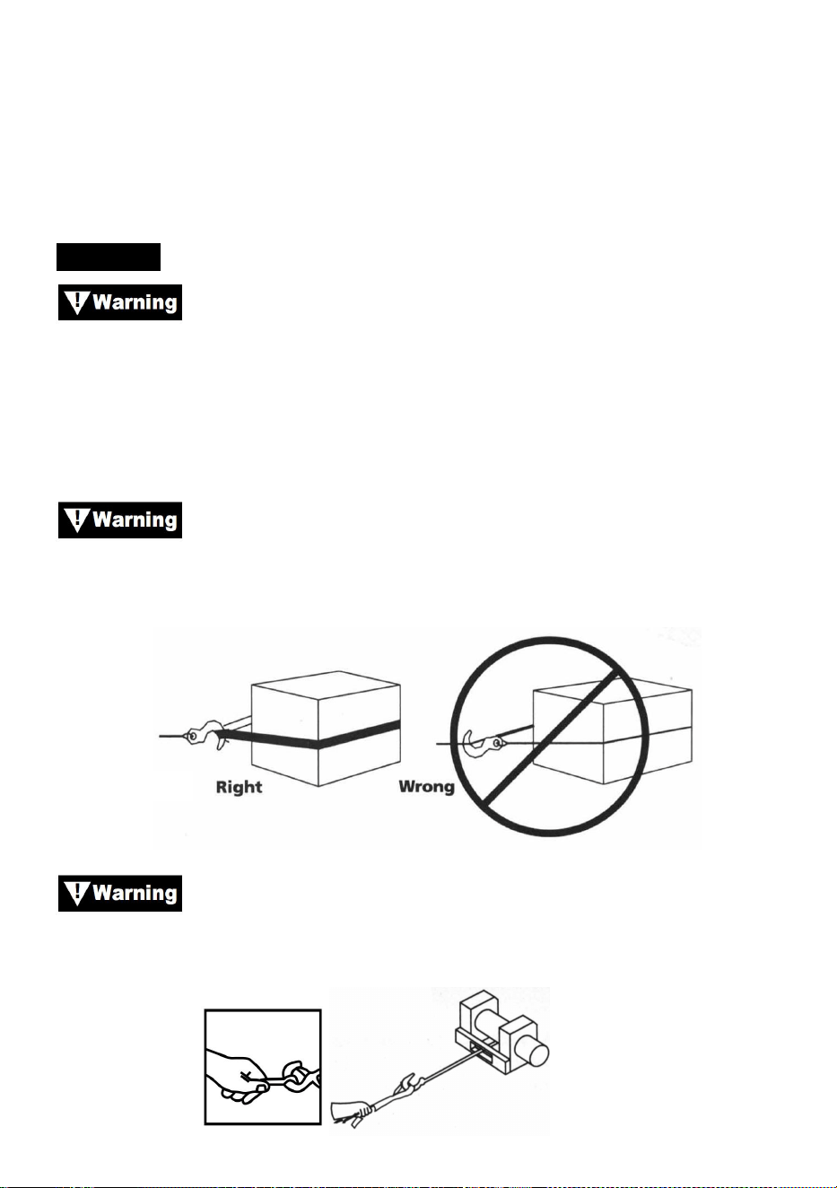
- 26 -
su lugar. Ninguno de nuestros cabrestantes está diseñado para
aplicaciones de sujeción de carga y puede desenrollarse o fallar debido a
la carga de impacto mientras se transporta la carga. La carga debe
asegurarse por otros medios y el gancho del cabrestante debe separarse
de la carga.
APAREJO
Tómese su tiempo al realizar el montaje e incluya un factor
de seguridad razonable. Un montaje inadecuado puede provocar daños al
vehículo y al equipo. También puede causar lesiones.
13.Nunca manipule el cable de acero ni el aparejo mientras otra persona
esté en el interruptor de control.
14.
Utilice una eslinga de nailon para sujetar el cable de acero a
un punto de anclaje. No vuelva a colocar el gancho en el cable de acero,
ya que podría romperlo.
Figura 16
Utilice siempre el protector de manos (véase la figura 17). No
sujete el gancho con la mano. Esto es importante no solo al enrollar el
cable de acero, sino también al retirarlo del cabrestante con el motor en
marcha.
Figura 17
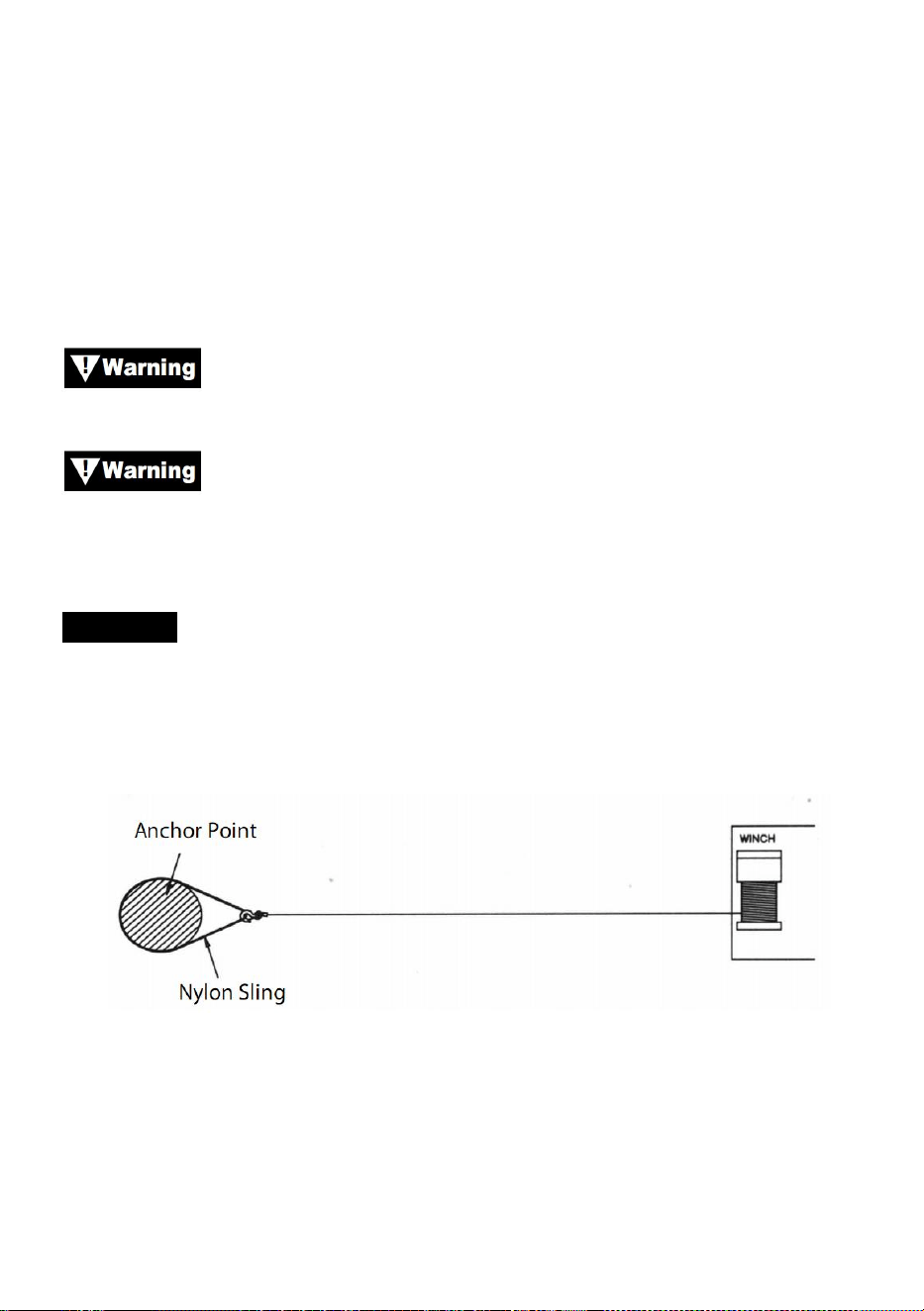
- 27 -
15.Haga funcionar el cabrestante de manera intermitente para tensar el
cable de acero. Cuando utilice un bloque de poleas, asegúrese de que el
cable de acero esté funcionando correctamente en todas las poleas antes
de aplicar una carga.
No vuelva a acoplar el embrague mientras el cabrestante
esté en funcionamiento.
Utilice siempre el cabrestante con una visibilidad despejada
de la operación de cabrestante. Nunca oculte las etiquetas de advertencia
e instrucciones.
APAREJO
3. La figura 18 ilustra el aparejo más comúnmente utilizado. Se utiliza una
eslinga de nailon para proteger el árbol cuando se utiliza como ancla y se
fija el cable de acero para utilizar la eslinga. No se recomienda el uso de
una cadena o un cable de acero debido al daño que podría causar al árbol.
Figura 18
24. La figura 19 ilustra un método de aparejo utilizado para obtener una
ventaja mecánica. El uso de un bloque de polea casi duplica la
capacidad de tracción de la línea. (Tenga en cuenta que el bloque de
polea no está incluido)
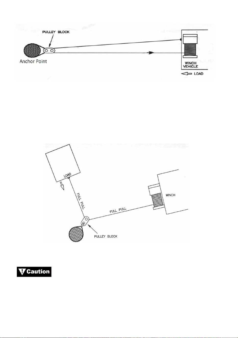
- 28 -
Figura 19
25. La figura 20 ilustra el uso de un bloque de polea para cambiar la
dirección de tracción. Se puede obtener una ventaja mecánica al unir
un bloque de polea a la eslinga de nailon con un grillete y pasar el
cable de acero hasta el punto de anclaje.
Figura 20
Los equipos tales como aparejos, ganchos, poleas, correas,
etc. deben tener el tamaño y la clasificación adecuados y deben
inspeccionarse periódicamente para detectar daños que puedan reducir su
resistencia.

- 29 -
MAINTAINNENCE
1) Compruebe periódicamente el apriete de los pernos de montaje y las
conexiones eléctricas. Elimine toda la suciedad o corrosión y manténgalas
siempre limpias.
2) No intente desmontar la caja de cambios. Las reparaciones deben ser
realizadas por el fabricante o un centro autorizado.
3) La caja de cambios se ha lubricado con grasa de litio de alta
temperatura y se ha sellado en fábrica. No se requiere lubricación interna.
TROUBLE SHOOTING
Síntomas
Posibles causas
Acción correctiva
El motor no funciona o
solo funciona en una
dirección
1.Interruptor inoperativo
2. Cables rotos o mala
conexión.
3. Motor dañado
1. Reemplace el interruptor
2. Compruebe si hay
conexiones defectuosas
3. Reemplazar o reparar el
motor.
El motor se calienta
mucho
1. Largo período de
funcionamiento.
2.falló o se eliminó
sobrecarga
3. Motor dañado
1.de bajo a frío
2.colocar o reparar sobrecarga
3. Coloque o repare el motor.

- 30 -
El motor funciona, pero
con potencia o velocidad
de línea insuficientes
1. Batería débil
2. El cable que conecta la
batería al cabrestante es
demasiado largo
3. Mala conexión de la
batería
4. Mala tierra
5. Motor dañado
1. Recargue o reemplace la
batería y verifique el sistema de
carga.
2. Mantenga el cabrestante
dentro de la distancia permitida
por los cables conductores.
3. Revise los terminales de la
batería para detectar corrosión
y límpielos según sea
necesario.
4. Conexiones limpias y
correctas
5. Coloque o repare el motor.
El cabrestante gira hacia
atrás
1. Cables Tor invertidos
2. Cables de picazón
invertidos
3.Interruptor de batería
instalado incorrectamente
1. Verifique el cableado
2. Verifique el cableado
3. Compruebe las conexiones
de la batería
El motor funciona pero el
tambor no gira
1. Embrague no acoplado
1. Acoplar el embrague
Costas del cabrestante
1.Carga excesiva
1. Reducir la carga o duplicar la
línea.
El motor funciona pero se
detiene
1.Carga
excesiva/sobrecarga
1.Dejar enfriar

- 31 -


Techniczny Wsparcie i certyfikat gwarancji elektronicznej www.vevor.com/support
WYCIĄGARKA ELEKTRYCZNA
MODELE: P2000-1/P3000-1C/P4000-1D/P4000-1W
We continue to be committed to provide you tools with competitive price.
"Save Half", "Half Price" or any other similar expressions used by us only represents an
estimate of savings you might benefit from buying certain tools with us compared to the major
top brands and does not necessarily mean to cover all categories of tools offered by us. You
are kindly reminded to verify carefully when you are placing an order with us if you are
actually saving half in comparison with the top major brands.


- 1 -
MODELE: P2000-1/P3000-1C/P4000-1D/P4000-1W
Have product questions? Need technical support? Please feel free to
contact us:
Technical Support and E-Warranty Certificate
www.vevor.com/support
NEED HELP? CONTACT US!
This is the original instruction, please read all manual instructions
carefully before operating. VEVOR reserves a clear interpretation of our
user manual. The appearance of the product shall be subject to the
product you received. Please forgive us that we won't inform you again if
there are any technology or software updates on our product.
ELECTRIC WINCH
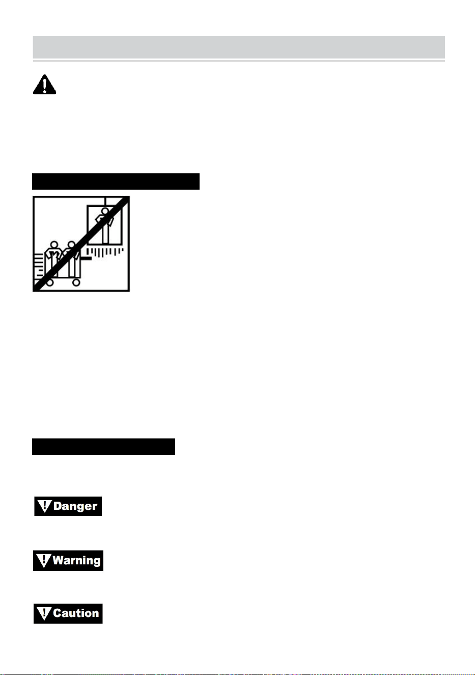
- 2 -
SAFE INSTRUCTIONS
OSTRZEŻENIE: Przed rozpoczęciem użytkowania należy uważnie
przeczytać i zrozumieć wszystkie INSTRUKCJE MONTAŻU I OBSŁUGI.
Nieprzestrzeganie zasad bezpieczeństwa i innych podstawowych środków
ostrożności może skutkować poważnymi obrażeniami ciała.
INFORMACJE O APLIKACJI N
Wciągarka ta jest przeznaczona do przesuwania ładunków na poziomie
gruntu lub w górę pochyłości. Nie jest ona zaprojektowana ani
przeznaczona do podnoszenia.
Wyciągarka nie jest przeznaczona do podnoszenia ani przenoszenia osób.
Ta wyciągarka jest przeznaczona do użytku okresowego ze względu na
gromadzenie się ciepła w różnych podzespołach. Jeśli końcówka silnika
stanie się nieprzyjemnie gorąca w dotyku, należy przerwać używanie
wyciągarki i odczekać, aż silnik ostygnie.
ŚRODKI OSTROŻNOŚCI
W całym podręczniku można znaleźć oznaczenia z następującymi
nagłówkami:
: Oznacza bezpośrednio niebezpieczną sytuację, która jeśli
się jej nie uniknie, spowoduje śmierć lub poważne obrażenia.
: Oznacza potencjalnie niebezpieczną sytuację, która, jeśli się
jej nie uniknie, może spowodować śmierć lub poważne obrażenia.
: Oznacza potencjalnie niebezpieczną sytuację, która, jeśli się

- 3 -
jej nie uniknie, może skutkować niewielkim lub umiarkowanym urazem. Ta
notacja jest również używana do ostrzegania przed niebezpiecznymi
praktykami.
Uwaga: Oznacza dodatkowe informacje dotyczące procedur instalacji
i obsługi Twojej wyciągarki.
Uwaga : Wciągarka jest przeznaczona głównie do zastosowań
przerywanych. Ta wciągarka nie jest przeznaczona do zastosowań
przemysłowych lub dźwigowych.
Zawsze używaj opaski zaciskowej na haczyku.
Podczas pracy trzymaj się z dala od wciągarki, liny stalowej i haka.
Nigdy nie używaj wyciągarki do podnoszenia lub przenoszenia osób.
Nigdy nie używaj wyciągarki do utrzymywania ładunku na miejscu.
OGÓLNE INFORMACJE DOTYCZĄCE BEZPIECZEŃSTWA
Twoja wyciągarka jest bardzo mocną maszyną. Jeśli jest używana
niebezpiecznie lub niewłaściwie, może to spowodować uszkodzenie
mienia lub obrażenia ciała.
Odpowiedzialność za bezpieczną instalację i obsługę
wyciągarki oraz zapobieganie obrażeniom ciała i uszkodzeniom mienia
ostatecznie spoczywa na Tobie, operatorze. Nie ma nic lepszego niż
stosowanie dobrej oceny i ostrożności podczas obsługi wyciągarki.
Lina stalowa może pęknąć zanim wyciągarka się zatrzyma.
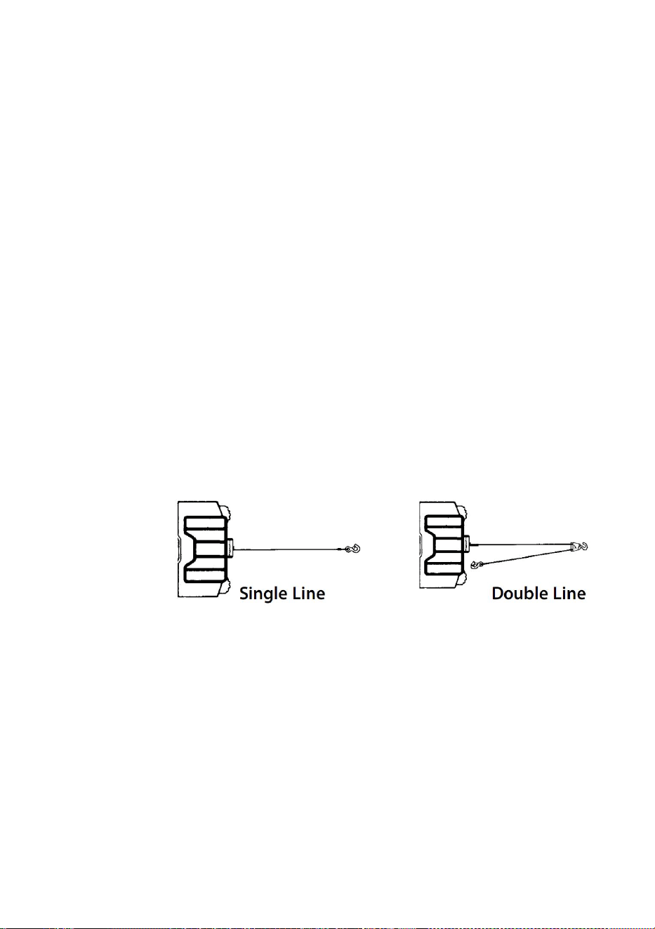
- 4 -
W przypadku dużych obciążeń należy użyć bloku linowego, aby
zmniejszyć obciążenie
lina stalowa.
146. Maksymalne obciążenie robocze znajduje się na warstwie liny
znajdującej się najbliżej bębna. NIE PRZECIĄŻAJ. NIE PRÓBUJ
DŁUGOTRWAŁEGO CIĄGNIĘCIA DUŻYCH ŁADUNKÓW.
Przeciążenia mogą uszkodzić wciągarkę i/lub linę stalową i stworzyć
niebezpieczne warunki pracy. W PRZYPADKU OBCIĄŻEŃ POWYŻEJ
1/2 UDŹWIGU NOMINALNEGO ZALECA SIĘ UŻYCIE
OPCJONALNEGO BLOKADY WCIĄGAJĄCEJ DO PODWÓJNEGO
NACIĄGU LINY STALOWEJ (RYSUNEK 1). Zmniejsza to obciążenie
wciągarki i naprężenie liny stalowej o około 50%. Przymocuj hak do
części nośnej. Silnik pojazdu powinien pracować podczas pracy
wciągarki. Jeśli znaczne wciąganie jest wykonywane przy wyłączonym
silniku, akumulator może być zbyt słaby, aby ponownie uruchomić
silnik.
Rysunek 1.
147. PO PRZECZYTANIU I ZROZUMIENIU TEJ INSTRUKCJI NAUCZ
SIĘ UŻYWAĆ WYCIĄGARKI. Po zainstalowaniu wyciągarki przećwicz
jej używanie, aby być z nią zaznajomionym, gdy zajdzie taka potrzeba.
148. NIE „poruszaj” pojazdem, aby pomóc wyciągarce w ciągnięciu
ładunku. Jednoczesne ciągnięcie przez wyciągarkę i pojazd może
spowodować przeciążenie liny stalowej i wyciągarki.
149. ZAWSZE STÓJ Z DALA OD LINY, HAKA I WCIĄGARKI. W
MAŁO PRAWDOPODOBNYM PRZYPADKU AWARII
JAKIEGOKOLWIEK KOMPONENTU NAJLEPIEJ BYĆ Z DALA OD
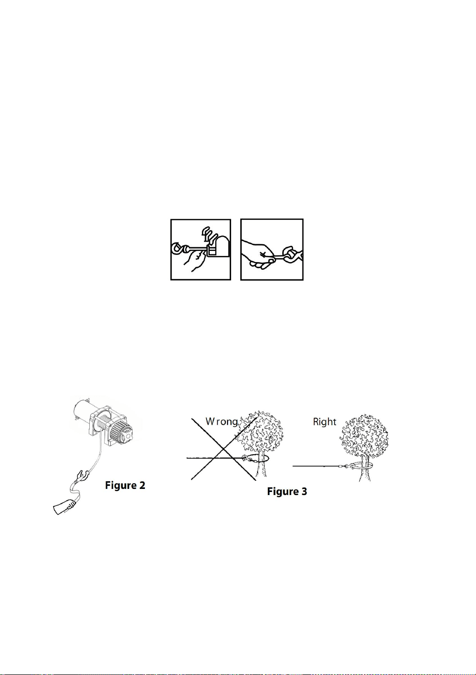
- 5 -
NIEBEZPIECZEŃSTWA.
150. Często sprawdzaj linę stalową i sprzęt. Przetartą linę stalową z
połamanymi włóknami należy natychmiast wymienić.
151. Używaj grubych skórzanych rękawic podczas obsługi liny stalowej.
Nie pozwól, aby lina stalowa przesuwała się przez twoje dłonie.
152. Nigdy nie używaj wyciągarki z mniejszą liczbą zwojów liny
nawiniętych na bęben, ponieważ mocowanie końcowe liny może NIE
wytrzymać pełnego obciążenia.
153. Nigdy nie wkładaj palca przez haczyk. Jeśli twój palec zostanie
uwięziony w haczyku, możesz go stracić .
154. ZAWSZE UŻYWAJ UCHWYTU RĄK podczas wprowadzania lub
wyprowadzania liny stalowej. (Zobacz rysunek 2).
155. NIGDY NIE ZACZEPIAJ LINY STALOWEJ Z POWROTEM DO
SIEBIE , ponieważ możesz uszkodzić linę stalową. Użyj nylonowej
taśmy (Rysunek 3).
156. Dobrym pomysłem jest położenie grubego koca lub kurtki na linie
stalowej w pobliżu końca haka podczas ciągnięcia ciężkich ładunków
(Rysunek 4). Jeśli nastąpi zerwanie liny stalowej, tkanina będzie
działać jak amortyzator i pomoże zapobiec trzepotaniu liny.

- 6 -
157. Unikaj ciągłego pociągania pod EKSTREMALNYMI KĄTAMI,
ponieważ może to spowodować spiętrzenie się liny na jednym końcu
bębna. Może to spowodować zacięcie się liny w wyciągarce, co może
spowodować uszkodzenie liny lub wyciągarki.
158. NIGDY NIE ZASŁANIAJ ETYKIET OSTRZEGAWCZYCH.
159. Zawsze obsługuj wyciągarkę mając dobrą widoczność podczas
pracy.
160. Sprzęt taki jak osprzęt, haki, zblocze, pasy itp. powinien być
dobrany wymiarowo do rodzaju zadania związanego z wyciąganiem i
okresowo sprawdzany pod kątem uszkodzeń, które mogłyby
zmniejszyć jego wytrzymałość.
161. NIGDY NIE ZWALNIAJ SPRZĘGŁA WOLNEGO SZPULA, GDY
WYCIĄGARKA JEST OBCIĄŻONA.
162. NIGDY NIE PRACUJ NA BĘBNIE WYCIĄGARKI LUB W JEJ
OKOLICY, GDY WYCIĄGARKA JEST OBCIĄŻONA.
163. NIE UŻYWAJ WYCIĄGARKI, JEŚLI JESTEŚ POD WPŁYWEM
NARKOTYKÓW, ALKOHOLU LUB LEKÓW.
164. ZAWSZE ODŁĄCZAJ PRZEWODY ZASILAJĄCE WYCIĄGARKI
OD AKUMULATORA PRZED ROZPOCZĘCIEM PRACY WEWNĄTRZ
BĘBNA WYCIĄGARKI LUB WOKÓŁ NIEGO, aby zapobiec
przypadkowemu włączeniu wyciągarki.
165. Podczas przenoszenia ładunku powoli naciągaj linę stalową, aż
się napręży. Zatrzymaj się, sprawdź ponownie wszystkie połączenia
wciągarki. Upewnij się, że hak jest prawidłowo osadzony. Jeśli
używana jest taśma nylonowa, sprawdź mocowanie do ładunku.
166. Podczas używania wyciągarki do przesuwania ładunku należy

- 7 -
ustawić skrzynię biegów pojazdu w położeniu neutralnym, zaciągnąć
hamulec pojazdu i zaklinować wszystkie koła.
167. NIE UŻYWAJ WYCIĄGARKI DO TRZYMANIA ŁADUNKÓW NA
MIEJSCU. Używaj innych środków do zabezpieczania ładunków, takich
jak pasy mocujące.
168. UŻYWAJ TYLKO PRZEŁĄCZNIKÓW, PILOTÓW I AKCESORIÓW
ZATWIERDZONYCH PRZEZ FABRYKĘ. Użycie komponentów
niezatwierdzonych przez fabrykę może spowodować obrażenia ciała
lub uszkodzenie mienia.
169. NIE PODDAWAJ SIĘ MASZYNIE ANI SPAWANIU ŻADNEJ
CZĘŚCI WYCIĄGARKI. Takie zmiany mogą osłabić integralność
strukturalną wyciągarki.
170. NIE PODŁĄCZAJ WYCIĄGARKI ANI DO PRĄDU
PRZEMIENNEGO 110 V, ANI DO SIECI NAPIĘCIOWEJ 220 V,
PONIEWAŻ MOŻE DOJŚĆ DO PRZEPALENIA WYCIĄGARKI LUB
ŚMIERTELNEGO PORAŻENIA PRĄDEM.
171. Nigdy nie należy poddawać wciągarki lub linę stalową
obciążeniom udarowym.
172. Zachowaj ostrożność podczas ciągnięcia lub opuszczania
ładunku w górę i w dół po rampie lub pochyłości. Trzymaj ludzi,
zwierzęta i mienie z dala od drogi ładunku.
173. Aby zapewnić bezpieczną pracę, zespół przełączników należy
utrzymywać w stanie wolnym od brudu i wilgoci.
174. Aby zapobiec nieautoryzowanemu użyciu wyciągarki, należy
zdemontować pilot zdalnego sterowania i przechowywać ją w czystym,
suchym miejscu, np. w schowku samochodowym.
PRODUCT SPECIFICATION

- 8 -
Zawartość opakowania
P2000-1
P3000-1C
P4000-1D
P4000-1W
Woltaż
12 V prądu
stałego
12 V prądu
stałego
12 V prądu
stałego
12 V prądu
stałego
Moc
znamionowa
0,95 KM
1,3 KM
2,2 KM
2,2 KM
Przełożenie
153:1
153:1
128.2:1
128.2:1
Długość
przewodu
1,8 mln
1,8 mln
1,8 mln
1,8 mln
Lina
Stal ,
5/32 cala * 39
stóp
Stal ,
3/16 cala *
39 stóp
Stal ,
1/4 cala * 39 stóp
Syntetyczny
1/4 cala * 39 stóp
Stopień
ochrony
IP
55
55
55
55
P2000-1
P3000-1C
P4000-1D
P4000-1W
Wyciągarka
elektryczna
1
1
1
1
Model
SPEC.
Model
Parts

- 9 -
PRODUCT ASSEMBLY INSTRUCTIONS
MONTAŻ WYCIĄGARKI
ZESTAWY MONTAŻOWE
PRODUCENT ZALECA UŻYCIE ZESTAWU MONTAŻOWEGO W CELU
Skrzynka
sterownicza
×
1
1
1
Bezprzewod
owy pilot
zdalnego
sterowania
×
1
1
1
Kontroler
uchwytu
1
1
1
1
Prowadnica
rolkowa
1
1
1
1
Uchwyt
montażowy
1
1
1
1
Hak
widełkowy
1
1
1
1
Czerwony
pasek
1
1
1
1
Zestaw śrub
1
1
1
1
Podręcznik
1
1
1
1
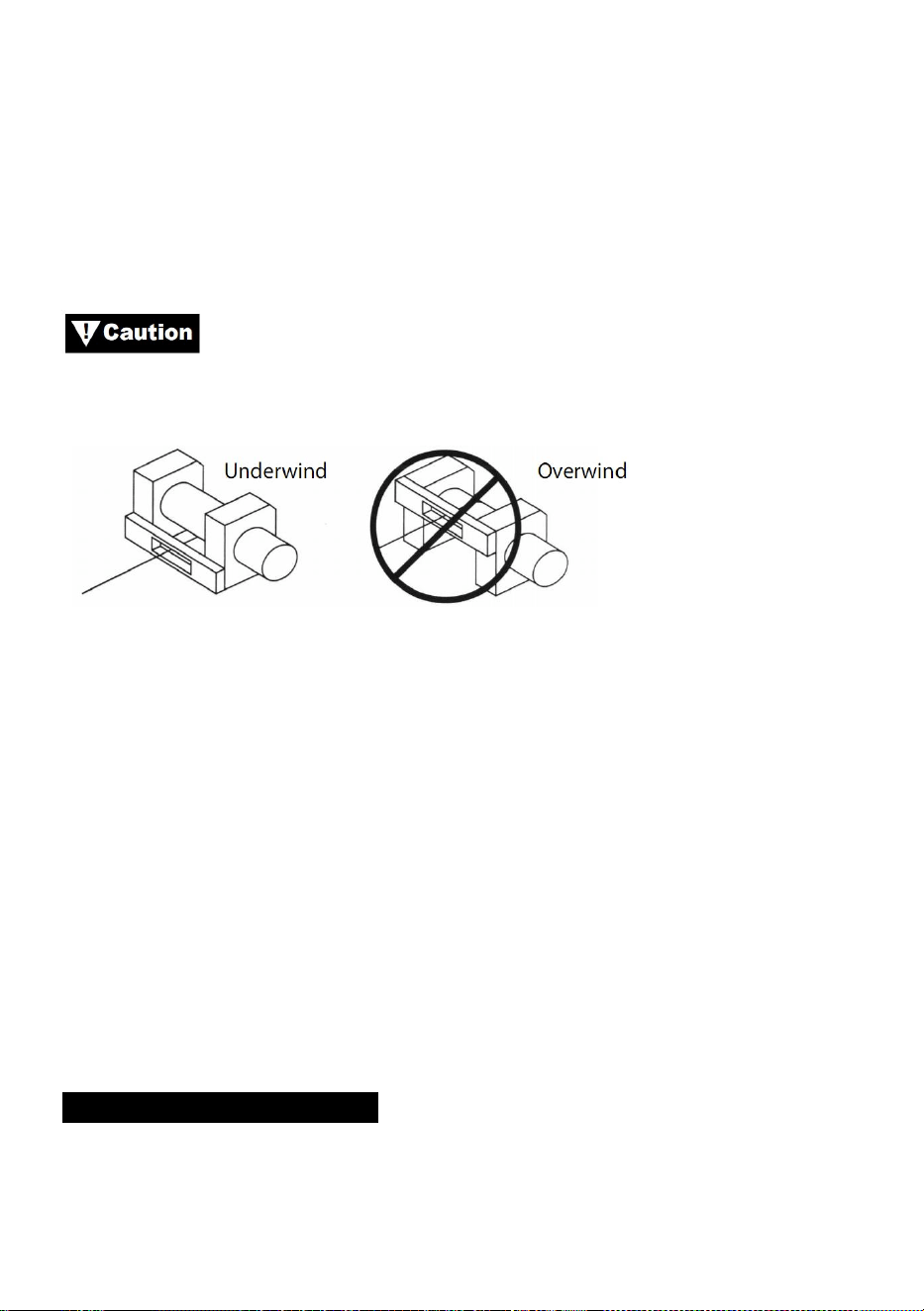
- 10 -
BEZPIECZNEGO MONTAŻU NA POJEŹDZIE. Zestawy montażowe
wyciągarki ATV są zazwyczaj dołączone do zestawu wyciągarki. Jeśli nie
zdecydujesz się na zakup zestawu montażowego, wyciągarka musi być
przymocowana do bezpiecznego i płaskiego miejsca montażowego.
Należy pamiętać, że bez niektórych urządzeń dołączonych do zestawu
może nie być możliwe bezpieczne użytkowanie wyciągarki.
Wciągarkę należy zamontować tak, aby lina stalowa była
zwinięta pod liną (rysunek 6).
Rysunek 6
Uwaga: Istnieje możliwość, a nie jest to niczym niezwykłym lub
niezalecanym, montażu wyciągarki w pozycjach innych niż przedstawione
w niniejszej instrukcji instalacji.
Chociaż położenie montażowe jest dowolne, zawsze pamiętaj, że
wciągarka ma być obsługiwana z liną stalową w położeniu nawiniętym na
bęben (Rysunek 1). Wciągarka jest zaprojektowana do WCIĄGANIA I
WYCIĄGANIA LINĄ w jednym kierunku. Nie próbuj odwracać działania
wciągarki.
INSTALACJA WYCIĄGARKI
Uwaga : Instalacja wyciągarki może przebiegać nieznacznie inaczej niż na
poniższych instrukcjach i schematach, w zależności od pojazdu,
wyciągarki, zestawu montażowego lub konstrukcji wspierającej.

- 11 -
Przed rozpoczęciem montażu wyciągarki odłącz przewód
uziemiający pojazdu oraz przewód dodatni od akumulatora.
MINIMALNE WYMAGANIA ELEKTRYCZNE
Upewnij się, że wybrałeś odpowiedni akumulator lub zasilacz do obsługi tej
wyciągarki. Jeśli wyciągarka jest intensywnie używana, zaleca się użycie
dodatkowego akumulatora i alternatora o dużej mocy.
PROCEDURA INSTALACJI:
KROK (1)
Zainstaluj zestaw montażowy lub przygotuj płaskie, bezpieczne miejsce
montażu dla wyciągarki, aby upewnić się, że silnik, bęben i skrzynia
biegów są prawidłowo wyrównane. Dokładnie postępuj zgodnie z
instrukcjami dołączonymi do zestawu montażowego.
Upewnij się, że konstrukcja wsporcza jest wystarczająco
mocna, aby utrzymać znamionowy udźwig wyciągarki.
Uwaga: Jeśli nie masz zestawu montażowego, będziesz musiał wywiercić
otwory w podparciu konstrukcyjnym. Upewnij się, że podparcie
konstrukcyjne ma grubość co najmniej 3/16” (5 mm).
Jeżeli do montażu wymagane są śruby, nakrętki, podkładki i
inne elementy o innej długości, należy zawsze używać elementów o klasie
wytrzymałości równej lub wyższej od elementów dostarczonych.
Krok ( 2 )
Umieść wyciągarkę nad otworami w zestawie montażowym lub podporze
konstrukcyjnej.
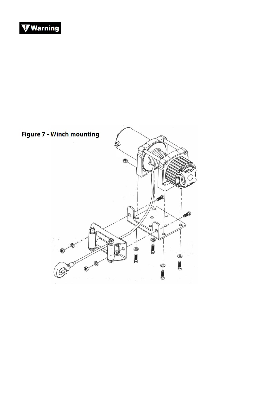
- 12 -
Podczas ustawiania wyciągarki upewnij się, że lina stalowa
nawija się na bęben w odpowiednim kierunku. Nieprawidłowe działanie
wyciągarki może spowodować nieprawidłowe działanie hamulca
wyciągarki (jeśli jest w wyposażeniu) i/lub awarię wyciągarki.
Krok (3)
Przymocuj wyciągarkę (rysunek 7) do zestawu montażowego lub
konstrukcji nośnej za pomocą śrub, podkładek zabezpieczających i
nakrętek kwadratowych dostarczonych wraz z wyciągarką.
Krok (4)
Zamocuj prowadnicę rolkową (rysunek 7) do płyty montażowej lub podpory
konstrukcji za pomocą dostarczonych elementów mocujących lub za
pomocą dwóch (2) śrub M8x20L ze stali o wytrzymałości na rozciąganie
8.8.

- 13 -
Upewnij się, że zarówno płyta montażowa, jak i osprzęt
wyciągarki zostały odpowiednio dokręcone.
Żadna część pojazdu (płyty ochronne, okablowanie, światła
pomocnicze, opony itp.) nie powinna utrudniać działania wyciągarki.
Podczas montażu sprawdź wszystkie części pojazdu i wyciągarki pod
kątem swobodnego działania. Upewnij się, że miejsce montażu wyciągarki
nie zmniejsza znacząco prześwitu.
MONTAŻ SKRZYNKI ELEKTROMAGNETYCZNEJ
16. Skrzynka elektromagnetyczna odłącza wyciągarkę od akumulatora po
wyłączeniu pojazdu.
17. Skrzynkę elektromagnesu należy zamontować blisko akumulatora, w
miejscu możliwie najczystszym i suchym.
18. Należy upewnić się, że wybrana lokalizacja skrzynki elektromagnesu
zapewnia wystarczającą odległość od wszystkich konstrukcji
metalowych, takich jak rury ramy.
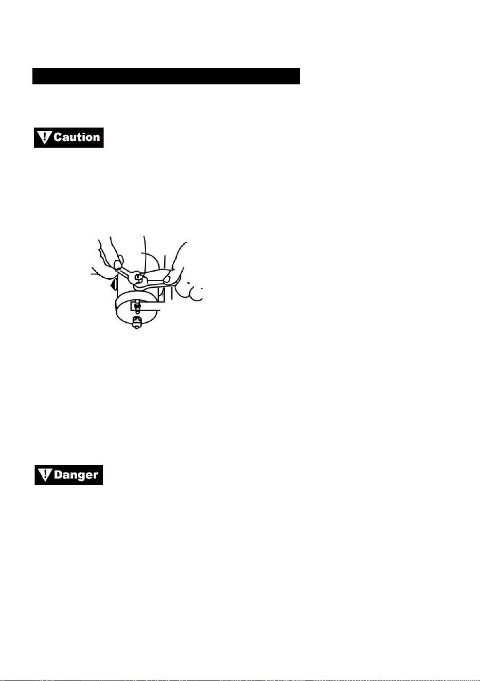
- 14 -
INSTALACJA PRZEŁĄCZNIKA KÓŁKOWEGO
ZASTOSOWANIA: SERIA ATV
Podczas podłączania przewodów do zacisków silnika lub
slenoidu przytrzymaj nakrętkę wewnętrzną kluczem, jednocześnie
dokręcając nakrętkę zewnętrzną drugim kluczem. Nie pozwól, aby zaciski
obracały się w swoich obudowach. Obrót może spowodować wewnętrzne
pęknięcie przewodu lub nieprawidłowe ustawienie części (Rysunek 9).
Rysunek 9 — Prawidłowe dokręcanie zacisków
Krok (1)
Przed przystąpieniem do prac elektrycznych należy sprawdzić, czy
przewód uziemiający pojazdu i przewód dodatni akumulatora są
odłączone.
NIE PRÓBUJ INSTALOWAĆ PRZEWODÓW, GDY
AKUMULATOR JEST PODŁĄCZONY. Akumulatory samochodowe
zawierają łatwopalne i wybuchowe gazy. Podczas instalacji noś okulary
ochronne i zdejmij całą metalową biżuterię. Nie pochylaj się nad
akumulatorem podczas wykonywania połączeń.
Krok (2)
Poprowadź wiązkę przewodów, mocując ją do twardych punktów w
pojeździe za pomocą opasek kablowych.
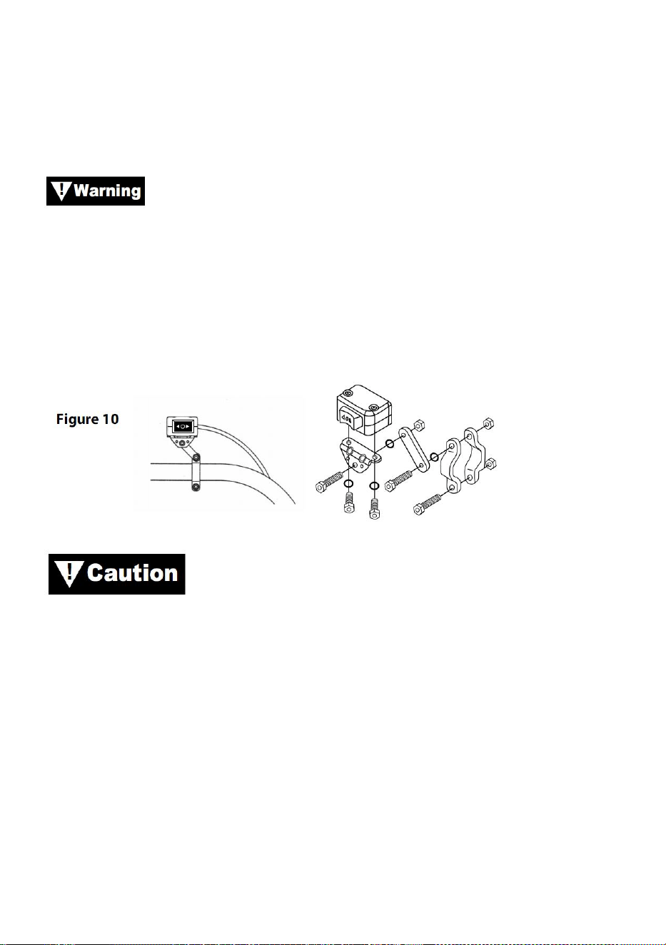
- 15 -
Uwaga: Podczas prowadzenia przewodów odpowiednie zaciski powinny
znajdować się w pobliżu akumulatora, punktu mocowania przełącznika i
wyciągarki. Wymagania dotyczące instalacji będą się różnić w zależności
od pojazdu i wyciągarki. Upewnij się, że przewody są wystarczająco długie,
aby sięgały do akumulatora, punktu mocowania przełącznika i wyciągarki.
Upewnij się, że wiązka przewodów nie koliduje ani nie styka
się z żadnymi gorącymi lub ruchomymi częściami silnika, zawieszenia,
układu kierowniczego, hamulcowego lub wydechowego.
Krok (3)
Za pomocą dostarczonych zacisków, uchwytu i osprzętu zamontuj
przełącznik kołyskowy w dogodnym miejscu. Zobacz rysunek 10.
ZAWSZE UŻYWAJ DOSTARCZONEGO UCHWYTU
MONTAŻOWEGO PRZEŁĄCZNIKA KOŁOWEGO, ŚRUB I NAKRĘTEK
KONTROLNYCH. Długości śrub są dobrane tak, aby zapewnić prawidłową
penetrację do skrzynki przełączników. Nadmierna penetracja może
spowodować zwarcia, które mogą prowadzić do przegrzania przewodu.
Krok (4)
Zaleca się montaż przełącznika na lewej kierownicy.
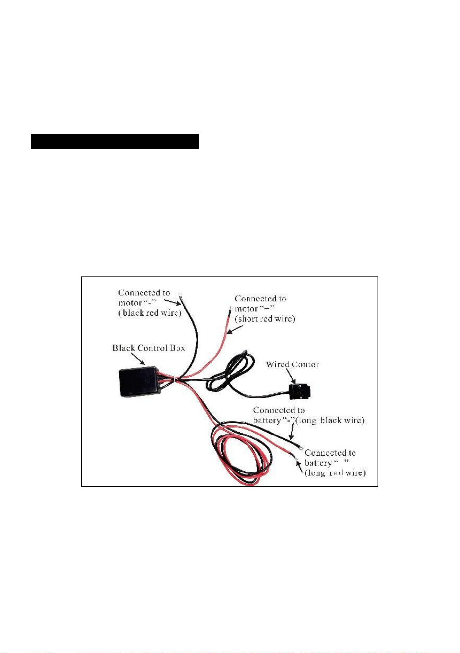
- 16 -
INSTALACJA ELEKTRYCZNA
Krok (1)
Poprowadź krótkie przewody w kolorze czerwonym i czarnym do
silnika.
Poprowadź długie przewody w kolorze czerwonym i czarnym do
akumulatora.

- 17 -

- 18 -
Krok ( 2 )
Sprawdź, czy przewody nie mają ostrych krawędzi i nie są narażone
na zgniecenia.
Zabezpiecz luźne przewody opaskami zaciskowymi lub taśmą
izolacyjną.
Nigdy nie pozostawiaj przełącznika podłączonego do prądu, gdy
wyciągarka nie jest używana.
PRODUCT INSTRUCTIONS
Przed sprawdzeniem działania wyciągarki należy odwinąć
około 60 cm liny stalowej.
JAZDA PRÓBNA
11. Sprawdź dokładnie, czy całe okablowanie jest prawidłowe i czy nie ma
odsłoniętych zacisków, które mogłyby spowodować zwarcie z ramą
pojazdu.
12. Przekręć kluczyk w stacyjce do pozycji ON. Sprawdź, czy wyciągarka
działa prawidłowo.
DZIAŁANIE BEZPŁATNEJ SZPULI
Pociągnij i przekręć gałkę sprzęgła do pozycji „Free”. Jeśli lina jest

- 19 -
obciążona, gałka sprzęgła może nie wyciągnąć się łatwo. NIE WCIĄGAJ
NA SIŁĘ GAŁKI SPRZĘGŁA. Zwolnij napięcie sprzęgła, wysuwając część
liny. Zwolnij sprzęgło, wyciągnij linę i zabezpiecz ją do zakotwiczenia lub
ładunku. Sprawdź, czy na bębnie pozostało co najmniej pięć zwojów liny.
Ponownie załącz bęben, ustawiając gałkę sprzęgła w pozycji „Engaged”.
Na chwilę włącz wyciągarkę w Cable Out, aby sprawdzić kierunek obrotu
bębna. Jeśli bęben obraca się w niewłaściwym kierunku, sprawdź
ponownie okablowanie.
Uwaga: Obróć pokrętło sprzęgła zgodnie ze strzałkami i instrukcjami
na nim, aby włączyć lub wyłączyć biegi wyciągarki.
Uwaga: Sprzęgło musi być całkowicie załączone przed wyciągarką.
Nigdy nie załączaj pokrętła sprzęgła, gdy bęben się obraca.
ZAANGAŻOWANY: WOLNY SZPULA:
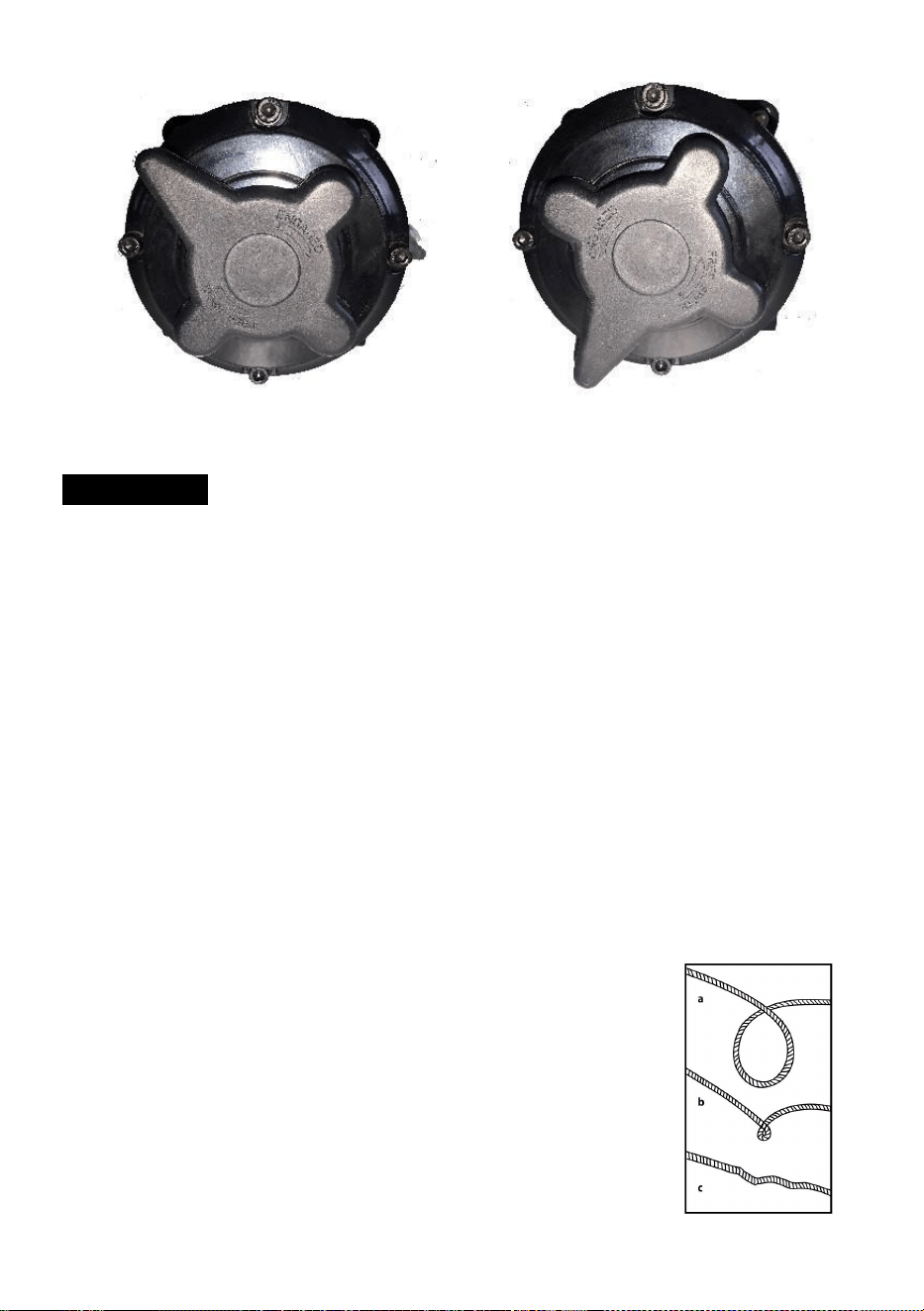
- 20 -
Lina stalowa
26. Żywotność liny stalowej jest bezpośrednio związana z opieką, jaką
otrzymuje. Lina stalowa w nowej wyciągarce i wszelkie liny zamienne
powinny zostać ponownie nawinięte pod obciążeniem co najmniej 100
funtów przed użyciem wyciągarki. Niewykonanie tego spowoduje
uszkodzenie liny stalowej. Przed użyciem sprawdź linę stalową.
Zgniecione, ściśnięte, postrzępione lub zagięte obszary znacznie
zmniejszają nośność. Wymień uszkodzoną linę stalową.
27. Zapobiegaj powstawaniu zagięć zanim wystąpią.
(p) To początek zagięcia. W tym momencie linę stalową należy
wyprostować.
(q) Lina stalowa została pociągnięta i pętla ma
naprężony do zagięcia. Lina stalowa jest teraz trwale
uszkodzone i nie powinny być używane.
(r) Skutkiem załamania jest to, że każde pasmo jest
ciągnięte
inna ilość powodująca, że pasma są pod spodem
największe napięcie potrzebne do zerwania i

- 21 -
zmniejszenia obciążenia
nośność liny stalowej.
28. Gdy konieczne jest ponowne nawinięcie liny stalowej bez obciążenia
po użyciu, trzymaj przewód przełącznika zdalnego w jednej ręce, a linę
stalową w drugiej. Rozpocznij z tak dużej odległości od pojazdu, na
jaką pozwala przełącznik zdalny, aktywuj przełącznik, przejdź kilka stóp
liny i zwolnij przełącznik. Powtórz proces. Zawsze zwalniaj przełącznik,
zanim twoja ręka znajdzie się w odległości czterech stóp od
prowadnicy (jeśli jest zamontowana).
29. Upewnij się, że lina stalowa jest równomiernie i ściśle rozłożona na
bębnie. Luźno nawinięty bęben pozwala linie stalowej przedostać się w
dół do warstw liny stalowej na bębnie i zaklinować się.
30. Nie zaleca się smarowania lub oliwienia liny stalowej ze względu na
zanieczyszczenie, które może skrócić żywotność liny.
WYMIANA LINKI STALOWEJ
26. Jeśli lina stalowa uległa zużyciu lub zaczynają pojawiać się oznaki
pękania włókien, należy ją wymienić przed ponownym użyciem. Aby to
zrobić, usuń uszkodzoną linę poprzez swobodne nawijanie. Wyjmij
śrubę z bębna i zwolnij linę.
27. Włóż koniec nowej liny i mocno dokręć śrubę.
28. Włącz sprzęgło i ponownie nawiń nową linę na bęben, utrzymując
napięcie liny podczas nawijania. Upewnij się, że lina jest ponownie
nawijana w pozycji pod wiatr.
Linę stalową należy wymieniać wyłącznie na identyczną
część zamienną zalecaną przez producenta.
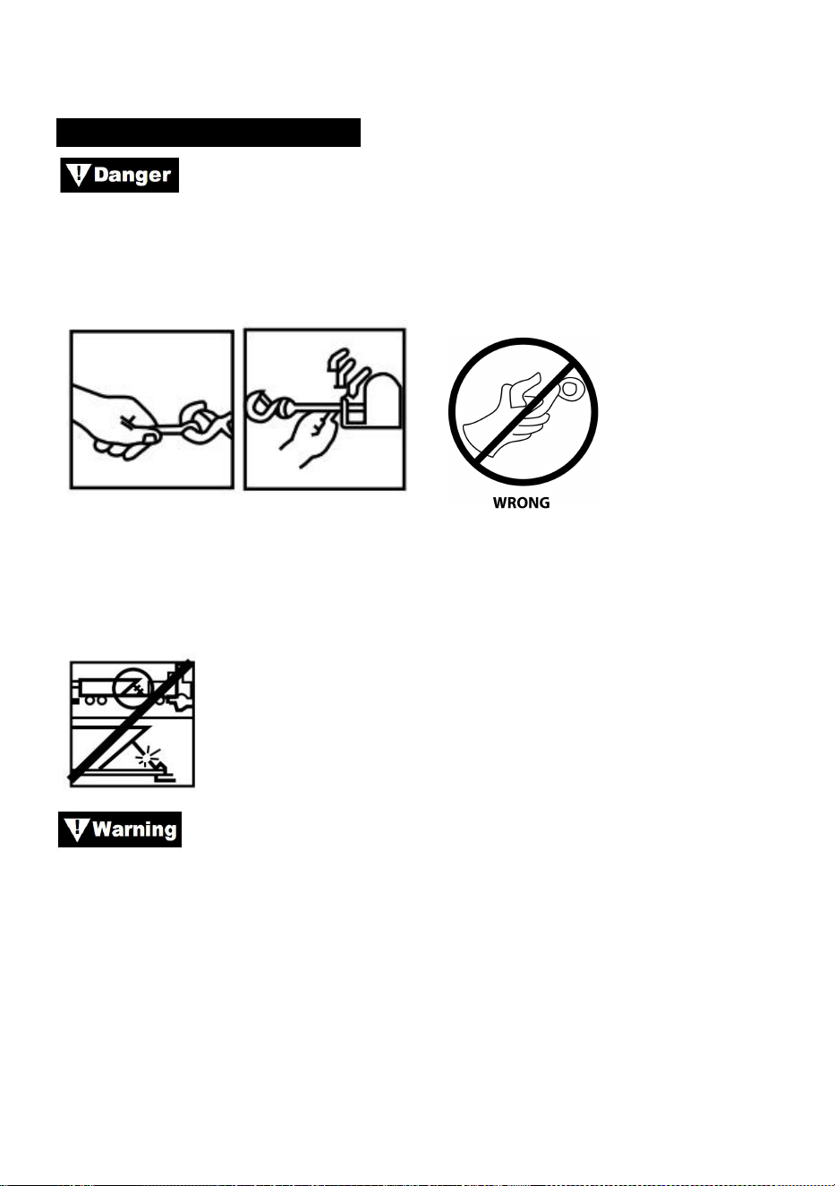
- 22 -
PRZYGOTOWANIE WEINCHA
Noś grube skórzane rękawice podczas obsługi liny stalowej,
nawet w rękawicach. Podczas obsługi haka zawsze używaj
zabezpieczenia rąk (patrz rysunek 12). Nigdy nie wkładaj palców do haka.
Włożenie palca(ów) do haka może spowodować obrażenia.
Rysunek 12
1. Podczas kotwiczenia pojazdu ciągnącego zaciągnij hamulec postojowy i
zablokuj lub zaklinuj koła. Trzymaj wciśnięty hamulec nożny pojazdu i
ustaw automatyczną i manualną skrzynię biegów w położeniu neutralnym.
Sprawdź przełącznik i okablowanie pod kątem pęknięć,
przytrzaśniętych miejsc, przetartych przewodów lub luźnych połączeń.
Uszkodzony, zwarty przewód może spowodować uruchomienie się
wyciągarki zaraz po podłączeniu.
1. Korzystając ze zdalnego przełącznika wewnątrz pojazdu, zawsze
umieszczaj go przez okno, aby uniknąć przytrzaśnięcia przewodu w
drzwiach.
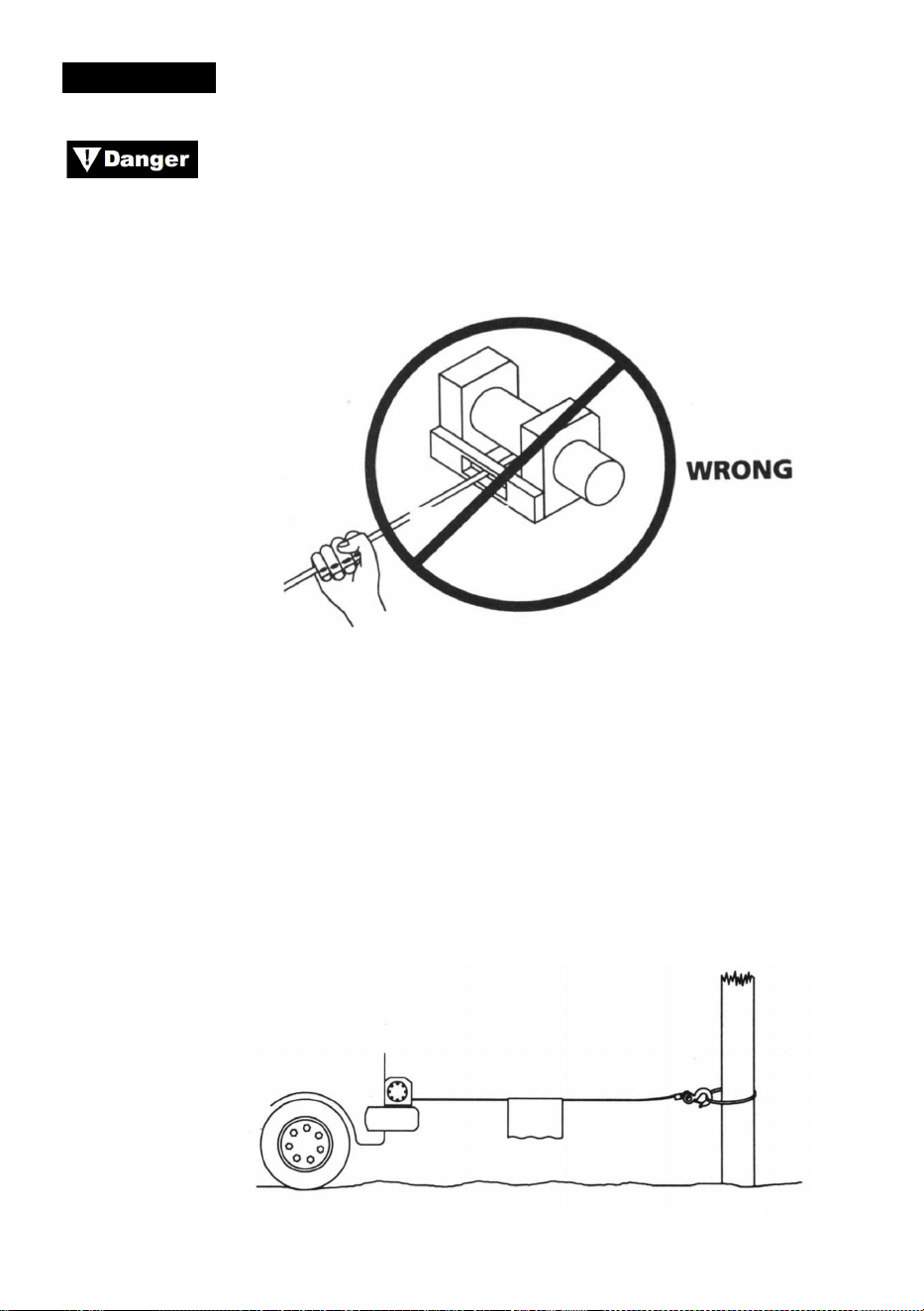
- 23 -
WCIĄGARKA
Nigdy nie dotykaj liny stalowej lub haka, gdy są napięte lub
pod obciążeniem. Nawet w stanie spoczynku wciągarka może mieć
napiętą linę stalową. Nigdy nie naciągaj naprężonej liny stalowej na bęben
rękami (patrz rys. 13).
Rysunek 13
1. Wciągarka z co najmniej pięcioma owinięciami liny stalowej wokół bębna
wciągarki. Przy mniejszej liczbie owinięć lina stalowa mogłaby się
poluzować od bębna pod obciążeniem.
2. Podczas ciągnięcia ładunku, umieść koc, kurtkę lub plandekę na linie
stalowej w pobliżu końca haka (patrz rys. 14). Spowolni to odrywanie się
zerwanej liny stalowej i pomoże zapobiec poważnym obrażeniom. Podnieś
maskę, aby chronić przednią szybę.
Rysunek 14
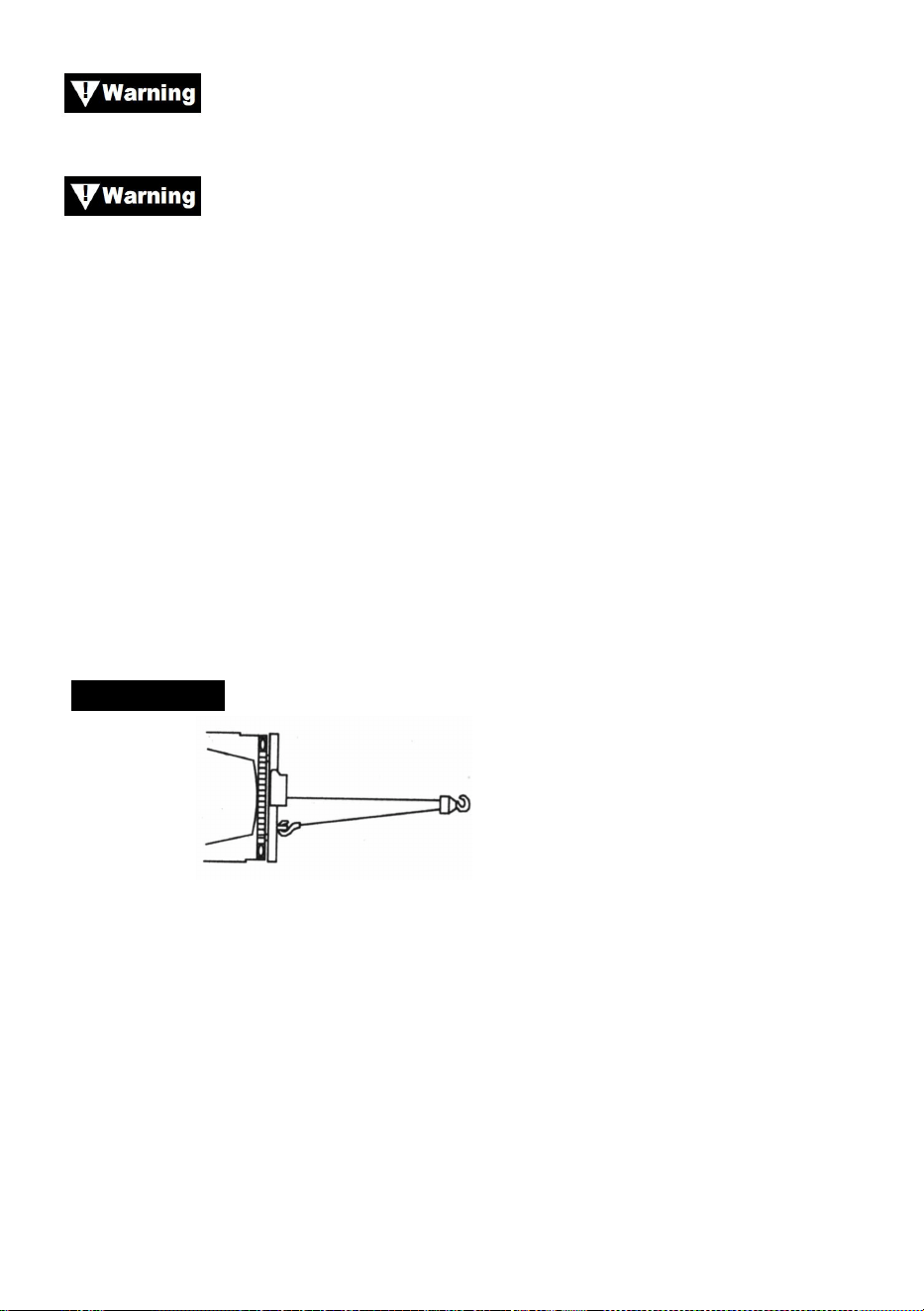
- 24 -
Zwróć uwagę na udźwig znamionowy wyciągarki i nie
przekraczaj go.
Gdy obciążenie przekroczy maksymalną moc znamionową
wyciągarki, zewnętrzny wyłącznik obwodu automatycznie wyłączy
wyciągarkę. Aby zresetować wyłącznik obwodu, zwolnij przycisk
przełącznika. Należy pamiętać, że wyciągarka nie będzie mogła ponownie
uruchomić się normalnie, dopóki ciepło silnika nagromadzone w wyniku
nadmiernego obciążenia nie ostygnie.
1. Podwójna lina z blokiem linowym (patrz rys. 15), aby zmniejszyć
obciążenie wciągarki, liny stalowej i akumulatora. Podwójna lina również
zmniejszy prędkość liny wciągarki. Upewnij się, że cały używany sprzęt
spełnia maksymalne parametry naciągu liny wciągarki. W przypadku
podwójnej liny bloki linowe powinny być ocenione na co najmniej
dwukrotność parametrów naciągu liny wciągarki.
WCIĄGARKA
Rysunek 15
1. Jeśli montujesz hak holowniczy do podwójnej linii, powinien on być
przymocowany do ramy pojazdu.
2. Wyposażenie wyciągarki w prowadnicę zmniejszy zużycie liny stalowej
podczas ciągnięcia pod kątem.
3. Ciągnij tak prosto, jak to możliwe, aby zredukować gromadzenie się liny
na jednym końcu bębna.
4. Silnik pojazdu powinien pracować podczas korzystania z wyciągarki.
Jeżeli dłuższe korzystanie z wyciągarki odbywa się przy wyłączonym
silniku, akumulator może być zbyt słaby, aby ponownie uruchomić silnik.

- 25 -
Użyj bloku linowego, aby uniknąć wciągania pod ostrymi
kątami. Nierównomierne ułożenie warstw spowoduje poważne
uszkodzenie wciągarki i liny stalowej. Można to naprawić, zabezpieczając
ładunek, rozwijając linę stalową i ponownie umieszczając ją na
przeciwległym końcu bębna.
Nie rozłączaj sprzęgła pod obciążeniem, jeśli Twoja
wyciągarka jest wyposażona w sprzęgło z wolnym biegiem, upewnij się, że
lina stalowa nie jest naprężona, gdy rozłączasz sprzęgło. Przed
wyciągnięciem ładunku upewnij się, że sprzęgło jest całkowicie załączone.
Użyj wyciągarki, aby przesunąć ładunek. Nie próbuj
wspomagać wyciągarki poprzez przesuwanie pojazdu. Połączenie
wyciągarki i ciągnięcia pojazdu może przeciążyć linę stalową, a ładunek
może złamać wyciągarkę.
Nigdy nie polegaj na wyciągarce, aby utrzymać ładunek na
miejscu. Żadna z naszych wyciągarek nie jest przeznaczona do
zastosowań związanych z podtrzymywaniem ładunku i może się rozwinąć
lub zawieść z powodu obciążenia udarowego podczas transportu ładunku.
Ładunek powinien być zabezpieczony innymi środkami, a hak wyciągarki
odłączony od ładunku.
OLINOWANIE
Nie spiesz się podczas montażu osprzętu i uwzględnij
rozsądny czynnik bezpieczeństwa. Niewłaściwy montaż osprzętu może
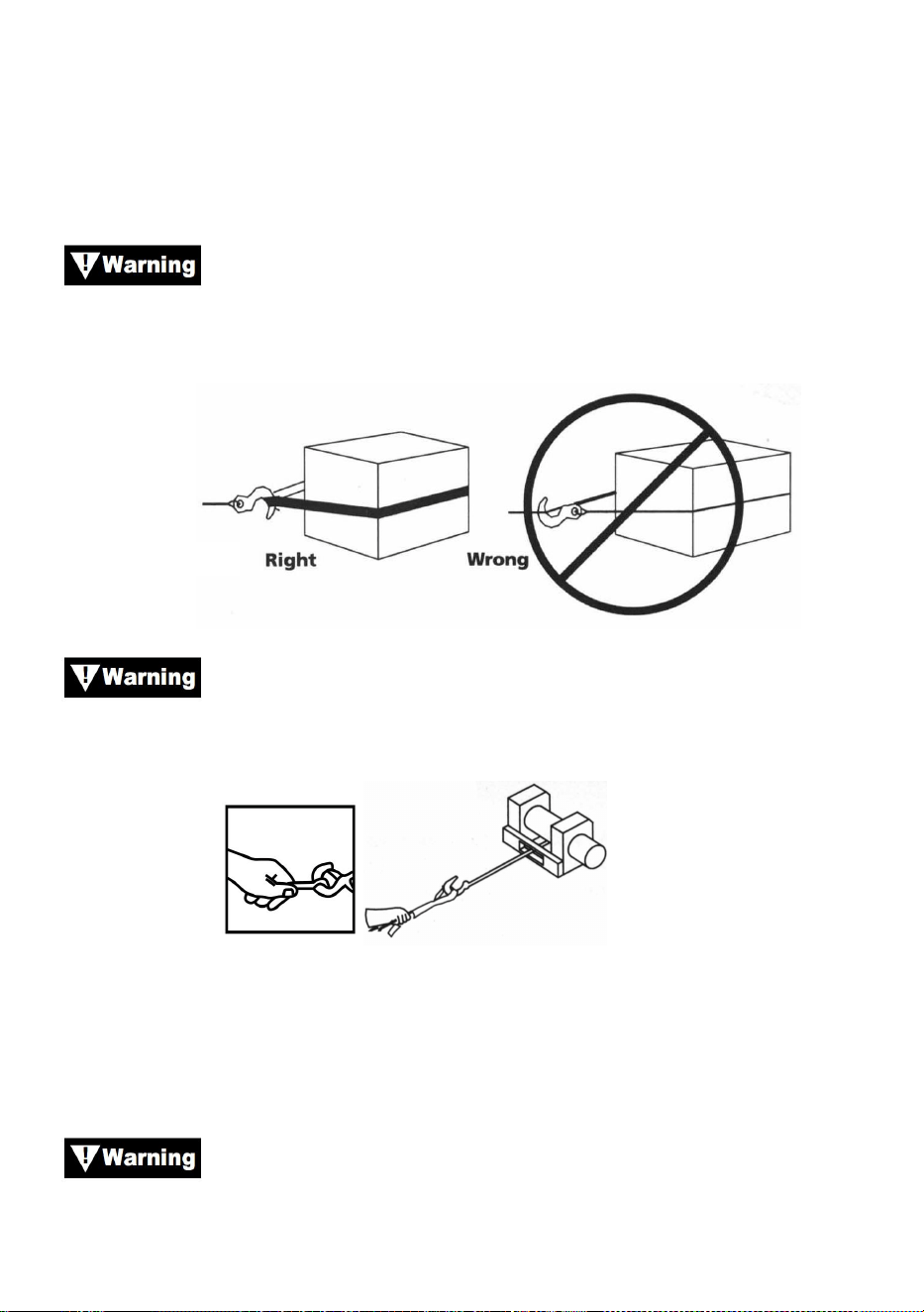
- 26 -
spowodować uszkodzenie pojazdu i sprzętu. Może również spowodować
obrażenia.
16.Nigdy nie dotykaj liny stalowej lub olinowania, gdy ktoś inny znajduje się
przy przełączniku sterującym.
17.
Użyj nylonowej taśmy, mocując linę stalową do punktu
kotwiczenia. Nie mocuj haka z powrotem do liny stalowej. Może to
spowodować zerwanie liny stalowej.
Rysunek 16
Zawsze używaj handsavera (patrz rys. 17). Nie trzymaj haka
ręką. Jest to ważne nie tylko podczas nawijania liny, ale również podczas
wyjmowania liny z wyciągarki pod napięciem.
Rysunek 17
18.Uruchom wciągarkę okresowo, aby usunąć luz liny. Podczas używania
bloku linowego upewnij się, że lina linowa porusza się prawidłowo we
wszystkich kołach linowych przed zastosowaniem obciążenia.
Nie załączaj sprzęgła, gdy wyciągarka pracuje.
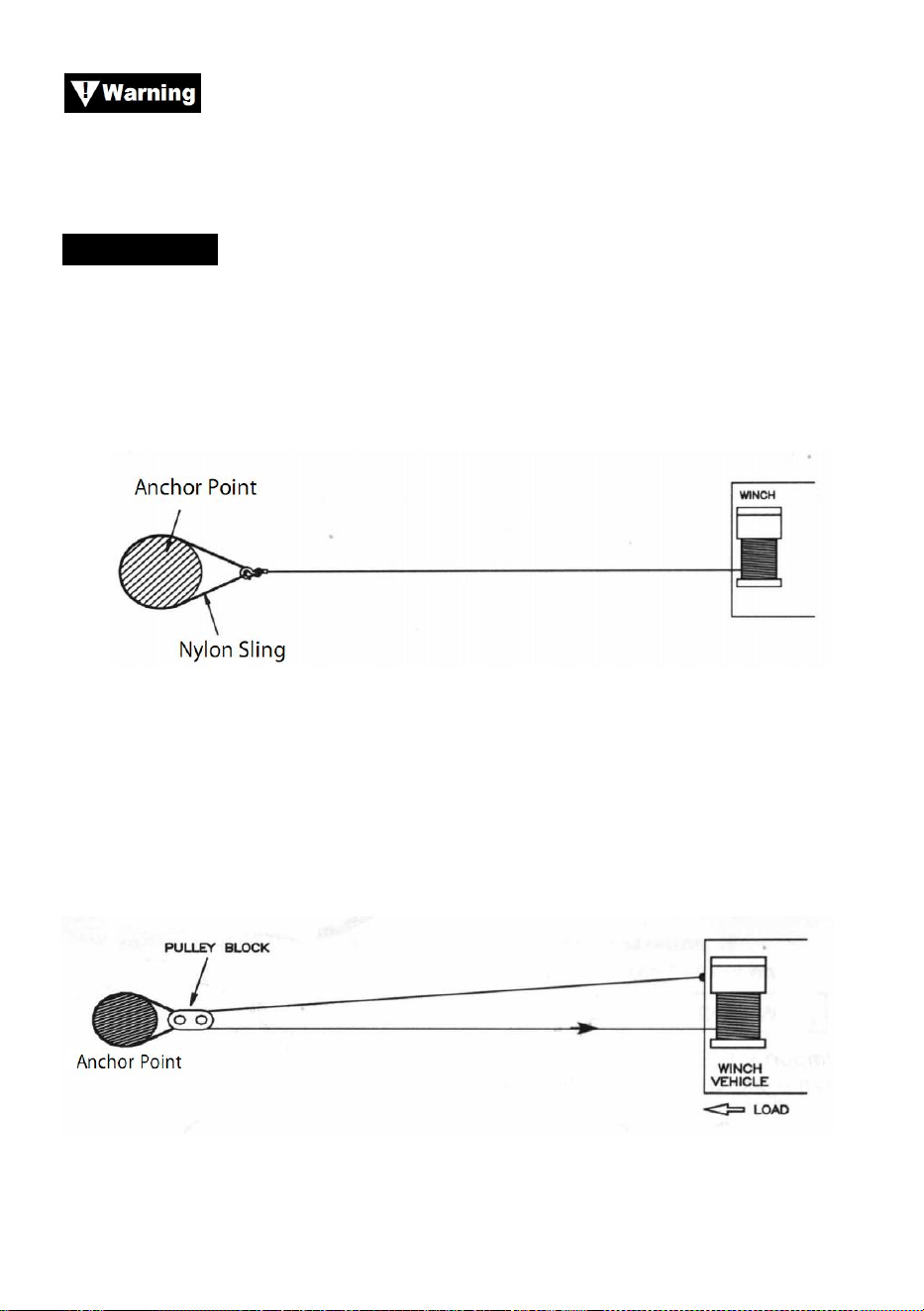
- 27 -
Zawsze obsługuj wyciągarkę, mając niezakłócony widok na
działanie wyciągarki. Nigdy nie zasłaniaj etykiet ostrzegawczych i
instrukcyjnych.
OLINOWANIE
3. Rysunek 18 ilustruje najczęściej stosowane olinowanie. Nylonowa
taśma jest używana do ochrony drzewa, gdy jest używane jako kotwica, a
lina stalowa jest przymocowana do użycia taśmy. Nie zaleca się używania
łańcucha lub liny stalowej ze względu na uszkodzenia, jakie może to
spowodować w drzewie.
Rysunek 18
29. Rysunek 19 ilustruje metodę olinowania wykorzystywaną do uzyskania
przewagi mechanicznej. Zastosowanie bloku linowego prawie podwaja
nośność liny ciągnącej. (Należy pamiętać, że blok linowy nie jest
uwzględniony)
Rysunek 19
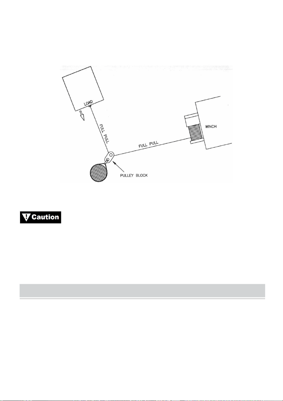
- 28 -
30. Rysunek 20 ilustruje użycie bloku linowego do zmiany kierunku
ciągnięcia. Przewagę mechaniczną można uzyskać, mocując blok
linowy do nylonowej taśmy za pomocą szekli i prowadząc linę stalową
do punktu kotwiczenia.
Rysunek 20
Sprzęt taki jak sprzęt wędkarski, haki, bloczki, pasy itp.
powinien mieć odpowiednie wymiary i parametry, a także podlegać
okresowym przeglądom w celu wykrycia uszkodzeń, które mogłyby
zmniejszyć jego wytrzymałość.
MAINTAINNENCE
1) Okresowo sprawdzaj dokręcenie śrub montażowych i połączeń
elektrycznych. Usuń cały brud lub korozję i zawsze utrzymuj czystość.
2) Nie próbuj demontować skrzyni biegów. Naprawy powinny być
wykonywane przez producenta lub autoryzowany serwis.
3) Skrzynia biegów została nasmarowana smarem litowym o wysokiej
temperaturze i jest uszczelniona w fabryce. Nie jest wymagane

- 29 -
wewnętrzne smarowanie.
TROUBLE SHOOTING
Objawy
Możliwe przyczyny
Działanie naprawcze
Silnik nie będzie działał lub
będzie działał tylko w
jednym kierunku
1. Przełącznik nie działa
2. Zerwane przewody lub
złe połączenie
3.Uszkodzony silnik
1. Wymień przełącznik
2. Sprawdź, czy połączenia nie
są słabe
3. Wymień lub napraw silnik
Silnik pracuje bardzo
gorąco
1.Długi okres eksploatacji
2.nieudane lub usunięte
przeciążać
3.Uszkodzony silnik
1.niski do chłodnego
2.umieść lub napraw
przeciążenie
3. Umieść lub napraw silnik
Silnik pracuje, ale ma
niewystarczającą moc lub
prędkość liniową
1.Słaby akumulator
2. Przewód łączący
akumulator z wyciągarką
jest zbyt długi
3. Słabe połączenie
akumulatora
4. Słabe podłoże
5.Uszkodzony silnik
1. Naładuj lub wymień
akumulator i sprawdź układ
ładowania
2. Trzymaj wyciągarkę w
odległości dozwolonej przez
przewody doprowadzające
3.Sprawdź zaciski akumulatora
pod kątem korozji i wyczyść w
razie potrzeby
4.Sprawdź i wyczyść połączenia
5.umieść lub napraw silnik
Wyciągarka działa do tyłu
1. przewody tor
odwrócone
2. druty swędzące
odwrócone
3. przełącznik elektryczny
1.okablowanie heck
2. sprawdź okablowanie
3.podłączenia akumulatora

- 30 -
zainstalowany
nieprawidłowo
Silnik pracuje, ale bęben
się nie obraca
1. Sprzęgło nie jest
załączone
1. Włącz sprzęgło
Wyciągarki
1. Nadmierne obciążenie
1.Zmniejsz obciążenie lub
podwójna linia
Operacje motoryczne, ale
się zatrzymują
1. Nadmierne
obciążenie/przeciążenie
1. Pozostawić do ostygnięcia


Technisch Ondersteuning en E-garantiecertificaat www.vevor.com/support
ELEKTRISCHE LIER
MODEL: P2000-1/P3000-1C/P4000-1D/P4000-1W
We continue to be committed to provide you tools with competitive price.
"Save Half", "Half Price" or any other similar expressions used by us only represents an
estimate of savings you might benefit from buying certain tools with us compared to the major
top brands and does not necessarily mean to cover all categories of tools offered by us. You
are kindly reminded to verify carefully when you are placing an order with us if you are
actually saving half in comparison with the top major brands.


- 1 -
MODEL: P2000-1/P3000-1C/P4000-1D/P4000-1W
Have product questions? Need technical support? Please feel free to
contact us:
Technical Support and E-Warranty Certificate
www.vevor.com/support
NEED HELP? CONTACT US!
This is the original instruction, please read all manual instructions
carefully before operating. VEVOR reserves a clear interpretation of our
user manual. The appearance of the product shall be subject to the
product you received. Please forgive us that we won't inform you again if
there are any technology or software updates on our product.
ELECTRIC WINCH
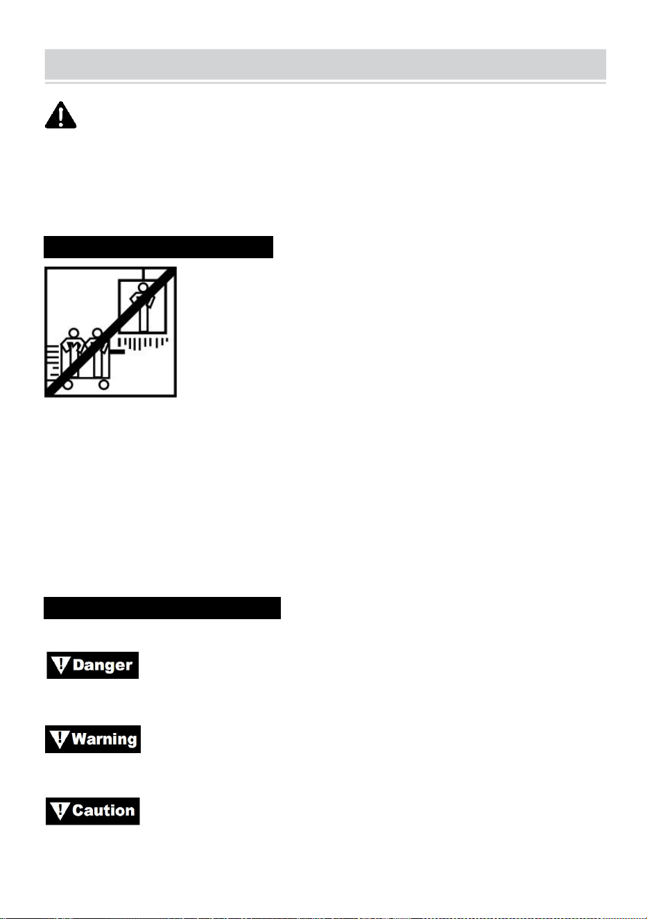
- 2 -
SAFE INSTRUCTIONS
WAARSCHUWING: Lees alle MONTAGE- EN
BEDIENINGSINSTRUCTIES zorgvuldig door en begrijp ze voordat u ze
gebruikt. Het niet naleven van de veiligheidsregels en andere
basisveiligheidsmaatregelen kan leiden tot ernstig persoonlijk letsel.
TOEPASSINGSINFORMATIE N
Deze lier is ontworpen om een last op grondniveau of een helling op te
verplaatsen. De lier is niet ontworpen of bedoeld om te hijsen.
Deze lier mag niet worden gebruikt om mensen op te tillen of te
verplaatsen.
Deze lier is bedoeld voor incidenteel gebruik vanwege de hitteontwikkeling
van verschillende componenten. Als het uiteinde van de motor
onaangenaam heet wordt om aan te raken, stop dan met het lieren en laat
de motor afkoelen.
VEILIGHEIDSMAATREGELEN
In deze handleiding vindt u notaties met de volgende koppen:
: Geeft een dreigende gevaarlijke situatie aan die, indien niet
vermeden, zal resulteren in de dood of ernstig letsel.
: Geeft een potentieel gevaarlijke situatie aan die, indien niet
vermeden, kan leiden tot de dood of ernstig letsel.
: Geeft een potentieel gevaarlijke situatie aan die, indien niet
vermeden, kan resulteren in licht of matig letsel. Deze notatie wordt ook
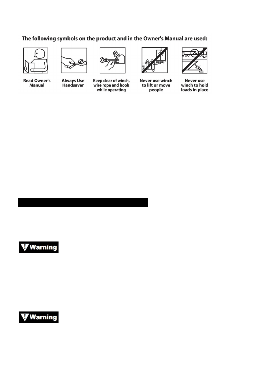
- 3 -
gebruikt om te waarschuwen voor onveilige praktijken.
Let op: Geeft aanvullende informatie aan in de installatie- en
bedieningsprocedures van uw lier.
Let op : De lier is primair ontworpen voor intermitterende toepassingen.
Deze lier is niet ontworpen voor gebruik in industriële of hijstoepassingen.
Gebruik altijd een handsaver aan de haak.
Blijf tijdens het gebruik uit de buurt van de lier, de staalkabel en de haak.
Gebruik de lier nooit om mensen op te tillen of te verplaatsen.
Gebruik nooit een lier om lasten op hun plaats te houden.
ALGEMENE VEILIGHEIDSINFORMATIE
Uw lier is een zeer krachtige machine. Als u deze onveilig of onjuist
gebruikt, Dit kan leiden tot materiële schade of persoonlijk letsel.
De verantwoordelijkheid voor de veilige installatie en
bediening van de lier en het voorkomen van persoonlijk letsel en materiële
schade ligt uiteindelijk bij u, de operator. Er is geen vervanging voor het
gebruik van gezond verstand en voorzichtigheid bij het bedienen van een
lier.
De staalkabel kan breken voordat de lier stopt.
Gebruik bij zware lasten een katrolblok om de belasting op de
staaldraad.
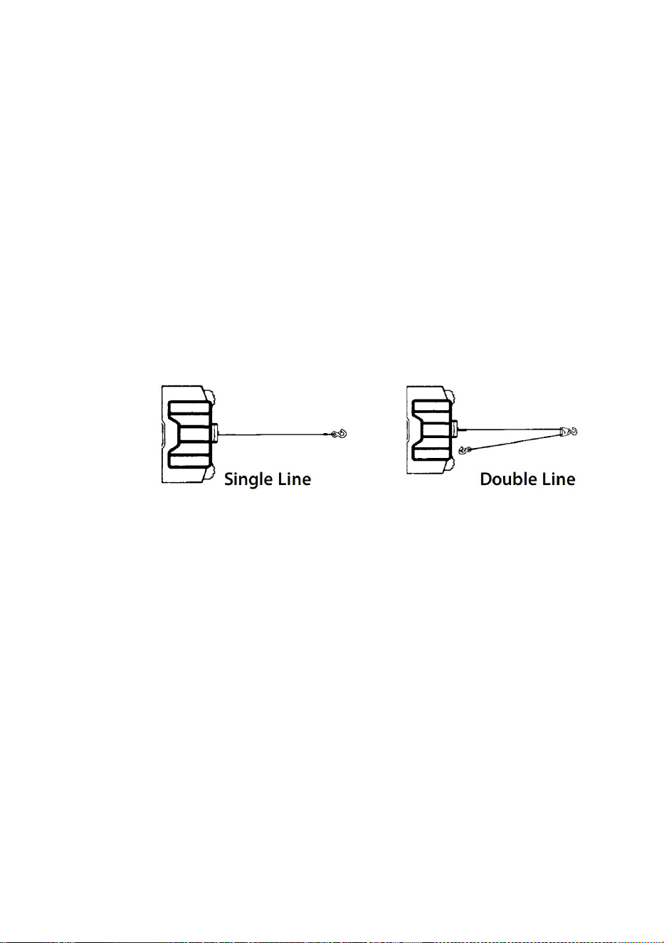
- 4 -
175. Maximale werklastcapaciteit is op de staaldraadlaag die het
dichtst bij de trommel zit. NIET OVERBELASTEN. PROBEER GEEN
LANGE TREKKRACHTEN TE TREKKEN BIJ ZWARE LADINGEN.
Overbelasting kan de lier en/of de staaldraad beschadigen en onveilige
bedrijfsomstandigheden creëren. VOOR LADINGEN BOVEN DE 1/2
NOMINALE CAPACITEIT, RADEN WIJ AAN HET OPTIONELE
POELIEBLOK TE GEBRUIKEN OM DE STAALDRAAD DUBBELE
TE LIJNEN (FIGUUR 1). Dit vermindert de belasting op de lier en de
spanning op de staaldraad met ongeveer 50%. Bevestig de haak aan
het lastdragende deel. De motor van het voertuig moet draaien tijdens
de lierwerking. Als er veel wordt gelierd met de motor uit, kan de accu
te zwak zijn om de motor opnieuw te starten.
Figuur 1.
176. NADAT U DEZE HANDLEIDING HEBT GELEZEN EN
BEGREPEN, LEER DAN UW LIER TE GEBRUIKEN. Oefen na het
installeren van de lier met het gebruik ervan, zodat u ermee vertrouwd
bent wanneer dat nodig is.
177. Verplaats uw voertuig NIET om de lier te helpen de last te trekken.
De combinatie van de lier en het voertuig die samen trekken, kan de
staalkabel en de lier overbelasten.
178. BLIJF ALTIJD UIT DE BUURT VAN STAALKABELS, HAKEN
EN LIER. IN HET ONWAARSCHIJNLIJKE GEVAL DAT EEN
ONDERDEEL DEFECT GAAT, IS HET BETER OM UIT DE BUURT
TE BLIJVEN.
179. Controleer staaldraad en apparatuur regelmatig. Een gerafeld
staaldraad met gebroken strengen moet onmiddellijk worden
vervangen.
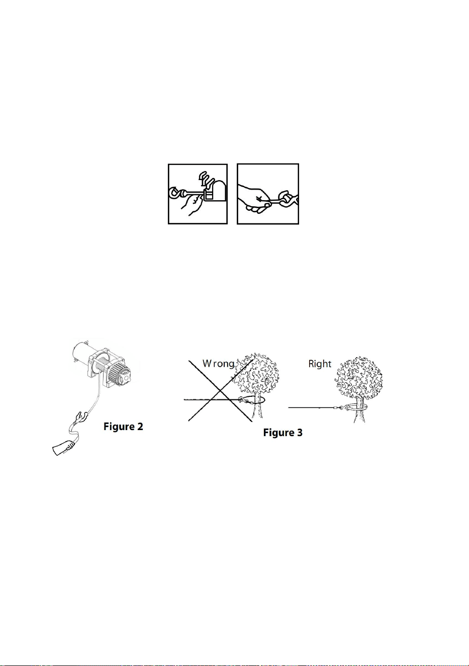
- 5 -
180. Gebruik dikke leren handschoenen bij het hanteren van
staaldraad. Laat staaldraad niet door uw handen glijden.
181. Gebruik nooit een lier met minder dan 5 windingen staaldraad
rond de liertrommel, omdat de bevestiging van het uiteinde van de
staaldraad mogelijk NIET de volledige belasting aankan.
182. Steek nooit uw vinger door de haak. Als uw vinger in de haak vast
zou zitten , zou u uw vinger kunnen verliezen .
183. GEBRUIK ALTIJD DE HANDSAVER wanneer u de staalkabel in-
of uitleidt (zie afbeelding 2).
184. HAAK DE STAALKABEL NOOIT TERUG AAN ZICHZELF ,
omdat u de staalkabel kunt beschadigen. Gebruik een nylon strop
(Figuur 3).
185. Het is een goed idee om een dikke deken of jas over de staalkabel
te leggen bij het uiteinde van de haak wanneer u zware lasten trekt
(Afbeelding 4). Mocht er een staalkabelbreuk optreden, dan fungeert
de doek als demper en voorkomt dat de kabel gaat zwiepen.

- 6 -
186. VERMIJD DIRECTE TREKKRACHTEN VANUIT EXTREME
HOEKEN, omdat de staalkabel zich dan aan één kant van de trommel
ophoopt. Hierdoor kan de staalkabel vastlopen in de lier, waardoor
schade aan de kabel of de lier ontstaat.
187. VERBERG NOOIT DE WAARSCHUWINGSLABELS.
188. Zorg er bij het bedienen van de lier altijd voor dat u vrij zicht hebt
op de lierwerking.
189. Apparatuur zoals takels, haken, katrollen, banden, etc. moeten
worden afgestemd op de liertaak en moeten regelmatig worden
gecontroleerd op beschadigingen die de sterkte ervan kunnen
verminderen.
190. LAAT DE VRIJLOOPKOPPELING NOOIT LOS ALS ER EEN
LAST OP DE LIER LIGT.
191. WERK NOOIT AAN OF ROND DE LIERTROMMEL ALS DE LIER
ONDER BELASTING STAAT.
192. GEBRUIK DE LIER NIET WANNEER U ONDER INVLOED BENT
VAN DRUGS, ALCOHOL OF MEDICIJNEN.
193. KOPPEL ALTIJD DE STROOMLEIDINGEN VAN DE LIER NAAR
DE ACCU AF VOORDAT U AAN OF IN DE ROND DE LIERTROMMEL
WERKT, zodat de lier niet per ongeluk kan worden ingeschakeld.
194. Bij het verplaatsen van een last, trek de staalkabel langzaam los
totdat deze strak staat. Stop, controleer alle lierverbindingen opnieuw.
Zorg dat de haak goed vastzit. Als er een nylon sling wordt gebruikt,
controleer dan de bevestiging aan de last.
195. Wanneer u uw lier gebruikt om een last te verplaatsen, dient u de
transmissie van het voertuig in de neutraal te zetten, de rem van het

- 7 -
voertuig aan te trekken en alle wielen te blokkeren.
196. GEBRUIK DE LIER NIET OM LADINGEN OP ZIJN PLAATS TE
HOUDEN. Gebruik andere middelen om ladingen vast te zetten, zoals
spanbanden.
197. GEBRUIK ALLEEN DOOR DE FABRIEK GOEDGEKEURDE
SCHAKELAARS, AFSTANDSBEDIENINGEN EN ACCESSOIRES. Het
gebruik van niet door de fabriek goedgekeurde componenten kan letsel
of schade aan eigendommen veroorzaken.
198. GEEN ENKEL ONDERDEEL VAN DE LIER MAKEN OF LASSEN.
Zulke veranderingen kunnen de structurele integriteit van de lier
verzwakken.
199. SLUIT DE LIER NIET AAN OP DE 110V AC-HUISSTROOM OF
DE 220V-NETVOEDING, WANT DIT KAN LEIDEN TOT EEN
DOORBRANDENDE LIER OF EEN FATALE SCHOK.
200. Zorg ervoor dat er nooit schokbelastingen op de lier of staalkabel
worden uitgeoefend.
201. Wees voorzichtig bij het op- en aftrekken van een lading op een
helling of helling. Houd mensen, huisdieren en eigendommen uit de
buurt van de lading.
202. Om een veilige werking te garanderen, moet de schakelaar vrij
van vuil en vocht worden gehouden.
203. Om onbevoegd gebruik van de lier te voorkomen, verwijdert u de
bedieningsknop en bergt u deze op in een schone, droge ruimte, zoals
het dashboardkastje.
PRODUCT SPECIFICATION

- 8 -
Pakketinhoud
P2000-1
P3000-1C
P4000-1D
P4000-1W
Spanning
12V DC
12V DC
12V DC
12V DC
Nominaal
vermogen
0,95 pk
1,3 pk
2,2 pk
2,2 pk
Overbrengin
gsverhoudin
g
153
:
1
153
:
1
128.2
:
1
128.2
:
1
Lengte van
de draad
1,8m
1,8m
1,8m
1,8m
Touw
Staal ,
5/32 inch * 39
voet
Staal ,
3/16 inch *
39 voet
Staal ,
1/4 inch * 39 voet
Synthetisch ,
1/4 inch * 39 voet
IP
-
classificatie
55
55
55
55
P2000-1
P3000-1C
P4000-1D
P4000-1W
Elektrische
lier
1
1
1
1
Model
SPEC.
Model
Parts

- 9 -
PRODUCT ASSEMBLY INSTRUCTIONS
MONTAGE VAN UW LIER
MONTAGEKITS
DE FABRIKANT BEVEELT HET GEBRUIK AAN VAN EEN MONTAGEKIT
VOOR EEN VEILIGE MONTAGE AAN UW VOERTUIG.
Bedieningsk
ast
×
1
1
1
Draadloze
afstandsbedi
ening
×
1
1
1
Bedieningsh
endel
1
1
1
1
Rolgeleider
1
1
1
1
Montagebeu
gel
1
1
1
1
Gaffelhaak
1
1
1
1
Rode band
1
1
1
1
Schroevens
et
1
1
1
1
Handmatig
1
1
1
1

- 10 -
ATV-liermontagekits zijn normaal gesproken inbegrepen in het lierpakket.
Als u ervoor kiest om geen montagekit te kopen, moet uw lier worden
bevestigd op een veilige en vlakke montagelocatie. Houd er rekening mee
dat uw lier mogelijk niet veilig kan worden bediend zonder bepaalde
apparatuur die in de kit is inbegrepen.
Deze lier moet met de staalkabel in de
onderwikkelrichting worden gemonteerd (Figuur 6).
Figuur 6
Let op: Het is mogelijk en niet ongebruikelijk of af te raden om uw lier te
monteren in andere standen dan aangegeven in deze
installatiehandleiding.
Hoewel de montagepositie naar eigen inzicht is, moet u er altijd rekening
mee houden dat uw lier bediend moet worden met de staalkabel in een
ondergewikkelde richting op de staalkabeltrommel (Afbeelding 1). Uw lier
is ontworpen om in één richting met het TOUW IN EN UIT te DRAGEN.
Probeer de werking van uw lier niet om te keren.
INSTALLATIE VAN DE LIER
Let op : Bij het installeren van een lier kan de installatie enigszins afwijken
van de onderstaande instructies en diagrammen, afhankelijk van uw
voertuig, lier, montageset of structurele ondersteuning.

- 11 -
Voordat u met de installatie van de lier begint, dient u de
aardingskabel en de positieve kabel van het voertuig los te koppelen
van de accu.
MINIMALE ELEKTRISCHE VEREISTEN
Zorg ervoor dat u de juiste accu of voeding selecteert om deze lier te
bedienen. Als de lier intensief wordt gebruikt, worden een hulpaccu en een
zware dynamo aanbevolen.
INSTALLATIEPROCEDURE:
STAP (1)
Installeer de montagekit of bereid een vlakke, veilige montagelocatie voor
de lier voor om ervoor te zorgen dat de motor, trommel en tandwielkast
correct zijn uitgelijnd. Volg de instructies die bij de montagekit zijn
meegeleverd zorgvuldig op.
Zorg ervoor dat de structurele ondersteuning sterk genoeg is
om de nominale capaciteit van de lier te ondersteunen.
Let op: Als u geen montagekit hebt, moet u gaten boren in de structurele
ondersteuning. Zorg ervoor dat uw structurele ondersteuning minimaal
3/16” (5 mm) dik is.
Als u voor uw installatie bouten, moeren, ringen en andere
bevestigingsmaterialen van verschillende lengte nodig hebt, gebruik dan
altijd bevestigingsmaterialen die even sterk of sterker zijn dan de
meegeleverde bevestigingsmaterialen.
Stap ( 2 )
Plaats de lier over de gaten in de montagekit of de structurele
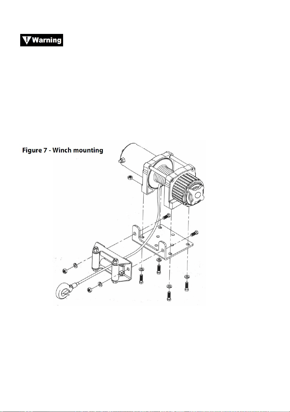
- 12 -
ondersteuning.
Zorg ervoor dat de staalkabel in de juiste rotatie op de
trommel draait als u de lier positioneert. Als u de lier niet in de juiste
richting bedient, kan de lierrem (indien aanwezig) niet goed werken en/of
kan de lier kapotgaan.
Stap (3)
Bevestig de lier (figuur 7) aan de montageset of de structurele steun met
behulp van de bouten, borgringen en vierkante moeren die bij de lier zijn
geleverd.
Stap (4)
Bevestig de rolgeleider (figuur 7) aan de montageplaat of de
constructiesteun met behulp van de meegeleverde hardware of met behulp
van twee (2) bouten van M8x 20L 8.8 Grade Tensile Steel.

- 13 -
Zorg ervoor dat zowel de montageplaat als de
lierhardware goed vastzitten.
Geen enkel onderdeel van het voertuig (skidplates, bedrading,
extra verlichting, banden, etc.) mag de werking van uw lier belemmeren.
Controleer bij het monteren alle voertuig- en lieronderdelen op vrije
werking. Zorg ervoor dat de montagelocatie van de lier de bodemvrijheid
niet aanzienlijk vermindert.
MONTAGE SOLENOÏDEKAST
19. De solenoïdekast koppelt uw lier los van de accu wanneer het voertuig
is uitgeschakeld.
20. De solenoïdekast moet dicht bij de accu worden gemonteerd, op een
plek die zo schoon en droog mogelijk is.
21. Zorg ervoor dat de gekozen locatie voor de solenoïdekast voldoende
afstand biedt tot alle metalen constructies, zoals framebuizen.
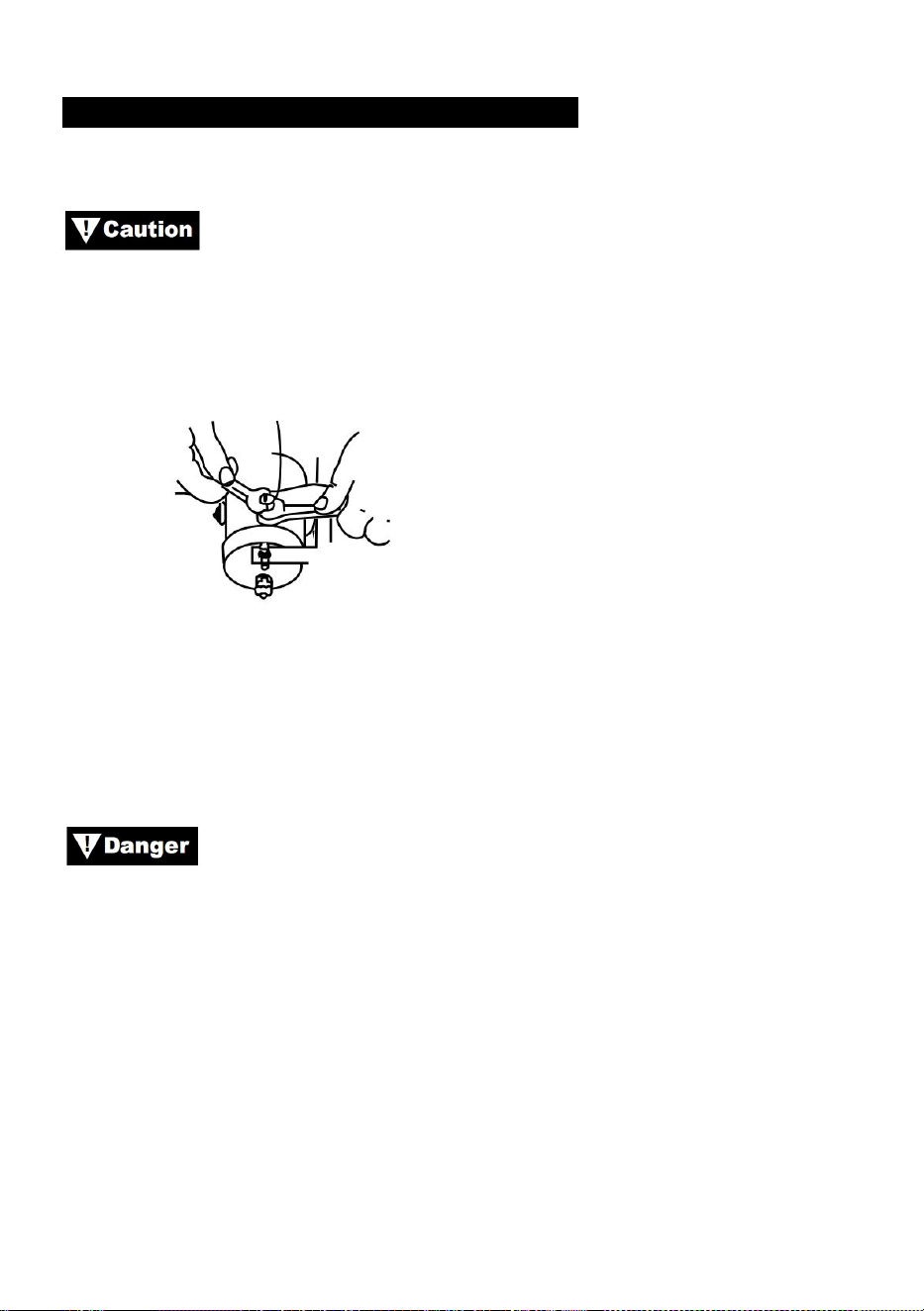
- 14 -
INSTALLATIE VAN DE TUIMELSCHAKELAAR
TOEPASSINGEN: ATV-SERIE
Bij het bevestigen van draden aan de motor- of
slenoid-aansluitingen, houdt u de binnenmoer vast met een sleutel terwijl u
de buitenmoer met een tweede sleutel vastdraait. Laat de aansluitingen
niet roteren in hun behuizingen. Rotatie kan interne draadbreuk of
verkeerde uitlijning van onderdelen veroorzaken (Figuur 9).
Figuur 9: Juiste klemvastzetting
Stap (1)
Controleer of de aarding van het voertuig en de positieve kabels van de
accu zijn losgekoppeld voordat u elektrische werkzaamheden uitvoert.
PROBEER NIET OM DE BEDRADING TE INSTALLEREN
WANNEER DE ACCU IS AANGESLOTEN. Autobatterijen bevatten
brandbare en explosieve gassen. Draag oogbescherming tijdens de
installatie en verwijder alle metalen sieraden. Leun niet over de batterij
terwijl u verbindingen maakt.
Stap (2)
Leid de kabelboom en bevestig deze met kabelbinders aan vaste punten
op het voertuig.
Let op: Bij het leggen van de draden moeten de juiste aansluitingen zich in
de buurt van de accu, het bevestigingspunt van de schakelaar en de lier
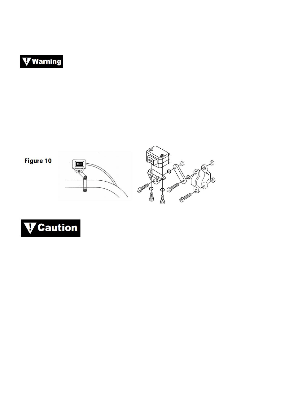
- 15 -
bevinden. Uw installatievereisten variëren afhankelijk van uw voertuig en
lier. Zorg ervoor dat de draden lang genoeg zijn om de accu, het
bevestigingspunt van de schakelaar en de lier te bereiken.
Zorg ervoor dat de kabelboom geen contact maakt met hete
of bewegende onderdelen van de motor, ophanging, besturing, remmen of
uitlaat.
Stap (3)
Gebruik de meegeleverde klemmen, beugel en hardware om de
tuimelschakelaar op een handige locatie te monteren. Zie Afbeelding 10.
GEBRUIK ALTIJD DE MEEGELEVERDE
TUIMELSCHAKELAAR MONTAGEBEUGEL, SCHROEVEN EN
BORGMOEREN. De schroeflengtes zijn afgestemd op de juiste penetratie
in de schakelkast. Overmatige penetratie kan leiden tot kortsluitingen die
kunnen leiden tot oververhitting van de draad.
Stap (4)
Het wordt aanbevolen om de schakelaar op de linker stuurhelft te
monteren.
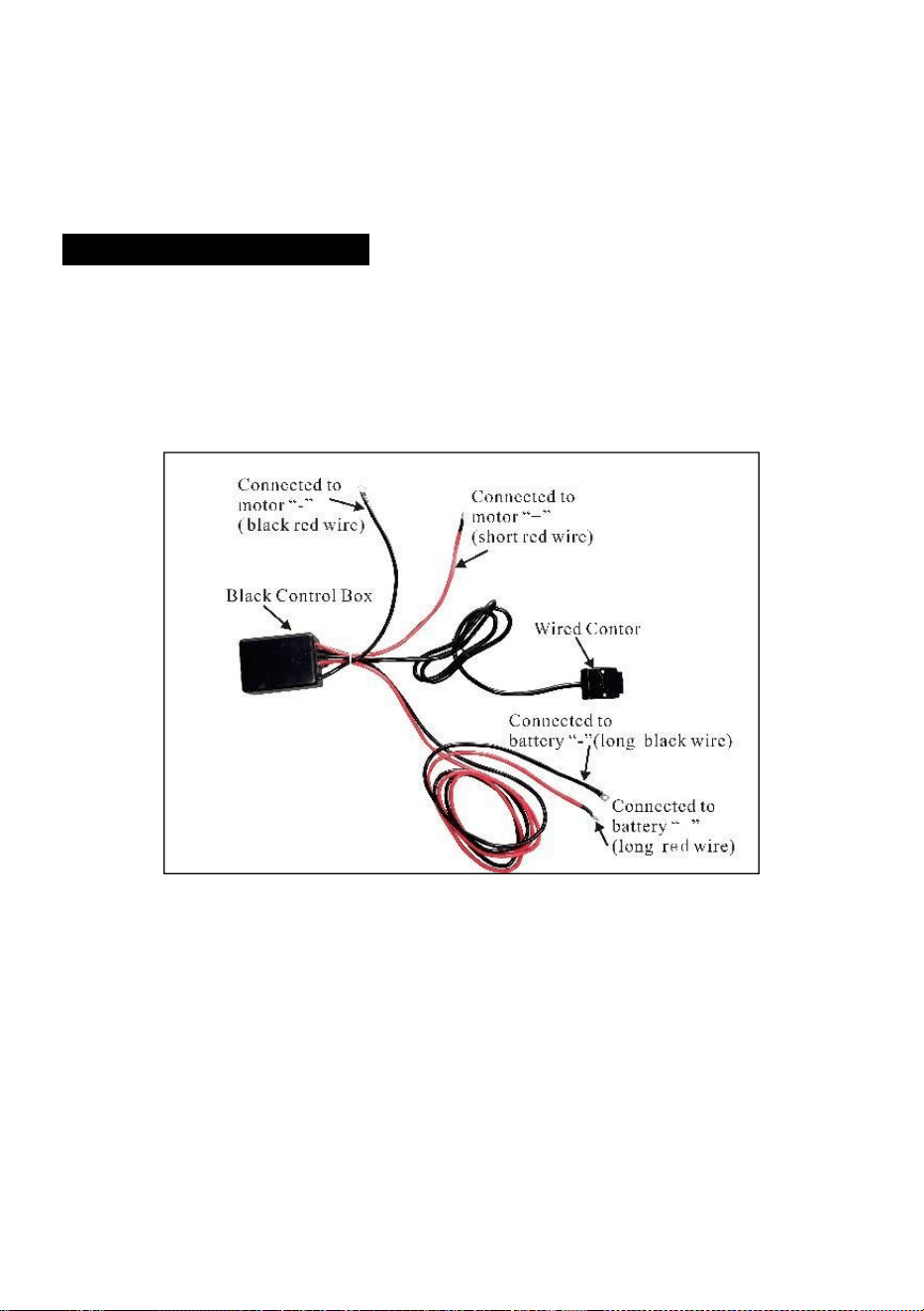
- 16 -
BEDRADING INSTALLATIE
Stap (1)
Leid de korte, rood en zwart gecodeerde draden naar de motor.
Leid de lange, rood en zwart gecodeerde draden naar de accu.

- 17 -

- 18 -
Stap ( 2 )
Controleer of alle bedrading vrij is van scherpe randen en
knelpunten.
Bevestig losse bedrading met kabelbinders of isolatietape.
Laat de schakelaar nooit in het stopcontact zitten als de lier niet in
gebruik is.
PRODUCT INSTRUCTIONS
Voordat u de werking van de lier test, moet u ervoor zorgen
dat u ongeveer 60 cm staalkabel afrolt.
PROEFRIT
13. Controleer nogmaals of alle bedrading correct is en of er geen
blootliggende aansluitingen zijn die kortsluiting met het chassis van het
voertuig kunnen veroorzaken.
14. Draai de contactsleutel naar de ON-positie. Controleer of de lier goed
werkt.
VRIJE SPOELWERKING
Trek en draai de koppelingsknop naar de "Vrij"-stand. Als er een last op de
staalkabel zit, kan de koppelingsknop er niet gemakkelijk uittrekken.
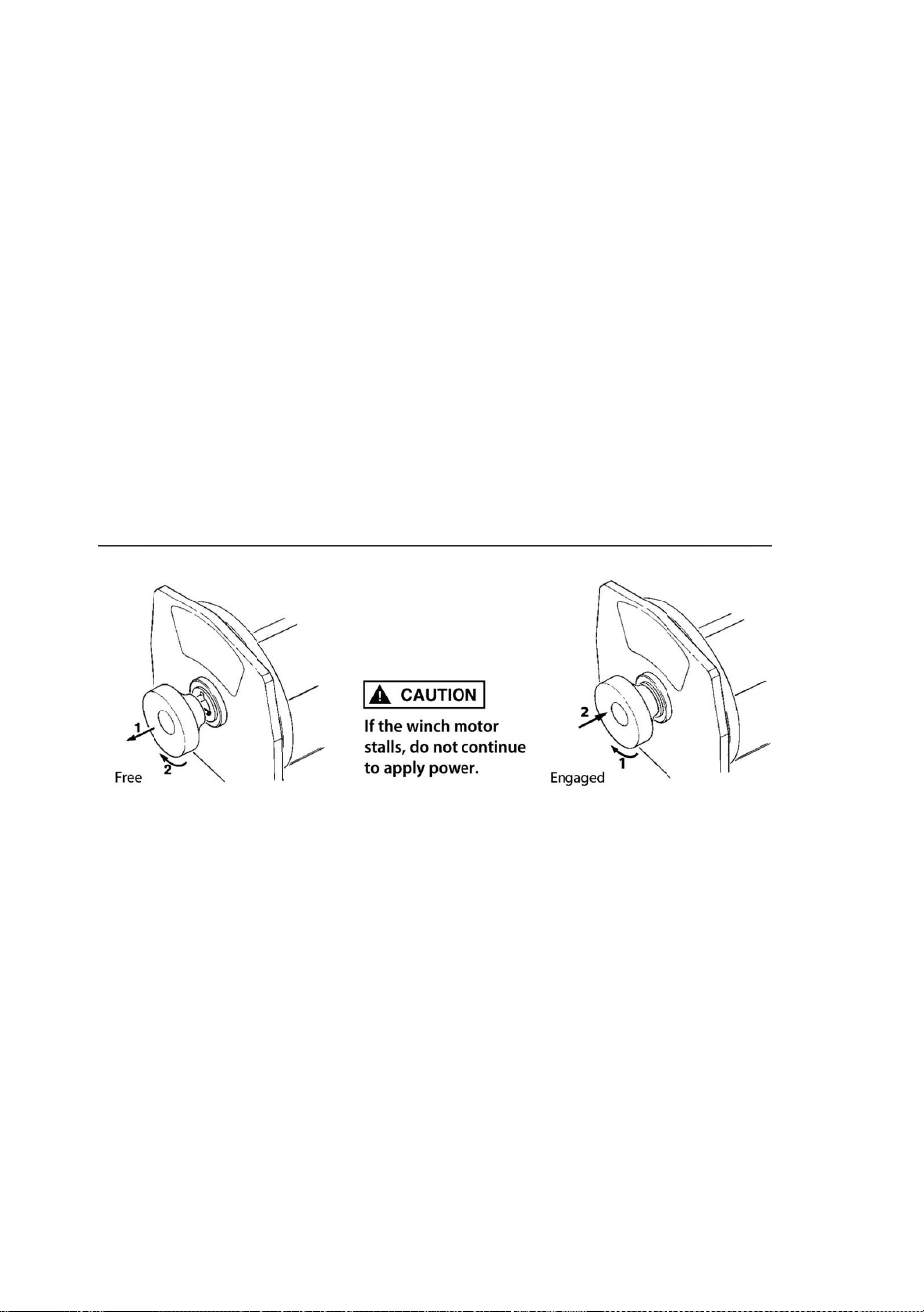
- 19 -
FORCEER DE KOPPELINGSKNOP NIET. Laat de spanning op de
koppeling los door een deel van de staalkabel eruit te joggen. Laat de
koppeling los en trek de staalkabel eruit en bevestig deze aan het anker of
de last. Controleer of er nog minstens vijf 5 windingen staalkabel op de
trommel zitten. Schakel de trommel weer in door de koppelingsknop terug
te zetten naar de "Ingeschakelde"-stand. Activeer de lier in Cable Out even
om de draairichting van de trommel te controleren. Als de trommel in de
verkeerde richting draait, controleer dan de bedrading opnieuw.
Let op: Draai de koppelingsknop volgens de pijlen en instructies op
de knop om de lieraandrijving in of uit te schakelen.
Let op: Koppeling moet volledig ingeschakeld zijn voor het lieren.
Schakel de koppelingsknop nooit in terwijl de trommel draait.
BETROKKEN: VRIJLOOP:
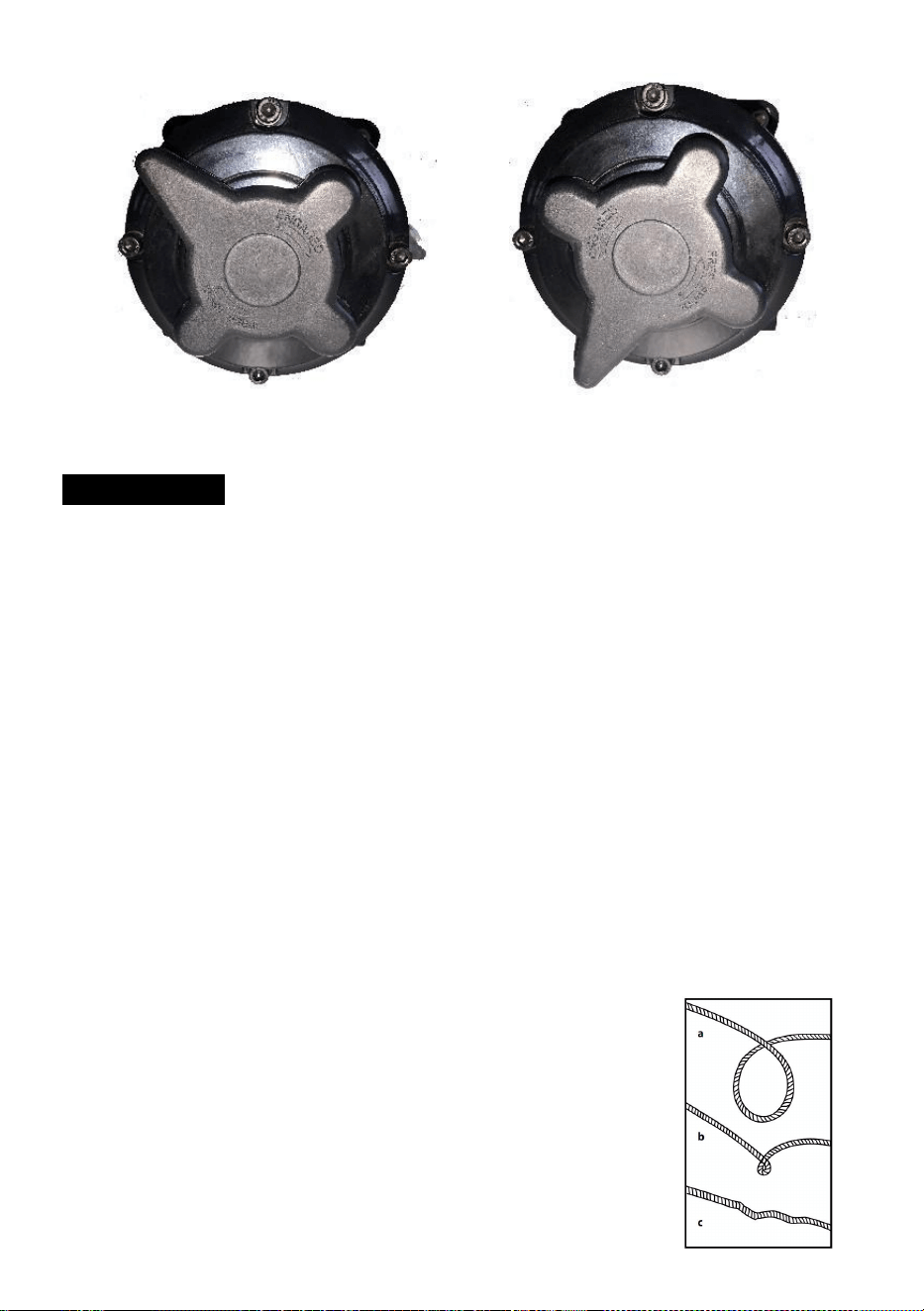
- 20 -
STAALKABEL
31. De levensduur van de staalkabel is direct gerelateerd aan de zorg die
deze krijgt. De staalkabel op een nieuwe lier en alle vervangende
kabels moeten opnieuw worden opgerold onder een minimale
belasting van 100 lb voordat de lier wordt gebruikt. Als u dit niet doet,
kan de staalkabel beschadigd raken. Controleer de staalkabel voor
gebruik. Geplette, geknepen, gerafelde of geknikte plekken
verminderen het draagvermogen aanzienlijk. Vervang de beschadigde
staalkabel.
32. Voorkom dat er problemen ontstaan.
(s) Dit is het begin van een knik. Op dit moment zou de staalkabel
rechtgetrokken moeten worden.
(t) Er werd aan het staaldraad getrokken en de lus is
losgeraakt.
vastgedraaid tot een knik. De staalkabel is nu
permanent
beschadigd zijn en niet gebruikt mogen worden.
(u) Het gevolg van knikken is dat elke streng trekt

- 21 -
een andere hoeveelheid waardoor de strengen onder
grootste spanning om te breken en de belasting te verminderen
capaciteit van de staalkabel.
33. Wanneer het nodig is om de staalkabel na gebruik zonder belasting
opnieuw op te wikkelen, houdt u de kabel van de afstandsbediening in
één hand en de kabel in de andere. Begin zo ver van het voertuig als
de afstandsbediening toelaat, activeer de schakelaar, loop een paar
meter over het touw en laat de schakelaar los. Herhaal het proces.
Laat de schakelaar altijd los voordat uw hand binnen vier voet van de
kabelgeleider komt (indien gemonteerd).
34. Zorg ervoor dat het staaldraad gelijkmatig en strak op de trommel is
verdeeld. Een losjes gewikkelde trommel zorgt ervoor dat het
staaldraad zich een weg naar beneden baant in de lagen staaldraad op
de trommel en vast komt te zitten.
35. Het is niet raadzaam om de staalkabel in te vetten of te oliën, omdat
vuil de levensduur van de staalkabel kan verkorten.
VERVANG DE STAALKABEL
31. Als de staalkabel versleten is of begint te breken, moet deze worden
vervangen voordat deze opnieuw kan worden gebruikt. Verwijder
hiervoor de defecte kabel door deze los te spoelen. Verwijder de bout
op de trommel en laat de kabel los.
32. Plaats het uiteinde van het nieuwe touw en draai de bout stevig vast.
33. Schakel de koppeling in en spoel het nieuwe touw opnieuw op de
trommel, waarbij u de spanning op het touw houdt terwijl het oprolt.
Zorg ervoor dat het touw opnieuw wordt opgerold in de
onderwindpositie.
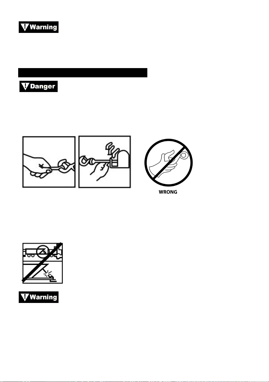
- 22 -
Vervang de staalkabel uitsluitend door identieke vervangende
onderdelen die door de fabrikant worden aanbevolen.
HET VOORBEREIDEN VAN DE MEISJE
Draag dikke leren handschoenen bij het hanteren van
staaldraad, zelfs met handschoenen aan. Gebruik bij het hanteren van de
haak altijd een handsaver (zie afbeelding 12). Steek nooit uw vingers in uw
haak. Vinger(s) in de haak steken kan leiden tot letsel.
Figuur 12
1. Bij het verankeren van het trekkende voertuig, zet de parkeerrem aan en
blokkeer of blokkeer de wielen. Houd de voetrem van het voertuig
ingedrukt en zet de automatische en handmatige transmissies in neutraal.
Controleer schakelaar en bedrading op scheuren, beknelde
plekken, gerafelde draad of losse verbindingen. Een beschadigde,
kortgesloten kabel kan ervoor zorgen dat de lier gaat draaien zodra deze is
aangesloten.
1. Wanneer u de afstandsbediening in een voertuig gebruikt, dient u deze
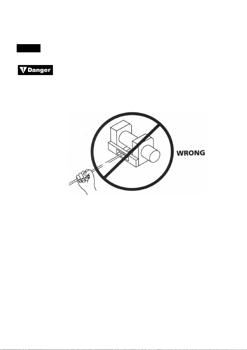
- 23 -
altijd door een raam te leiden om te voorkomen dat de kabel in de deur
bekneld raakt.
LIEREN
Raak de staalkabel of haak nooit aan als deze onder
spanning of belasting staat. Zelfs in rust kan de lier de staalkabel onder
spanning hebben. Leid nooit een staalkabel onder spanning met uw
handen op de trommel (zie Afb. 13).
Figuur 13
1. Lier met minstens vijf wikkelingen staalkabel rond de liertrommel. Met
minder wikkelingen kan de staalkabel losraken van de trommel onder
belasting.
2. Wanneer u een last trekt, leg dan een deken, jas of zeildoek over de
staalkabel bij het haakuiteinde (zie Afb. 14). Dit vertraagt het terugspringen
van een gebroken staalkabel en helpt ernstig letsel te voorkomen. Til de
motorkap op om de voorruit te beschermen.
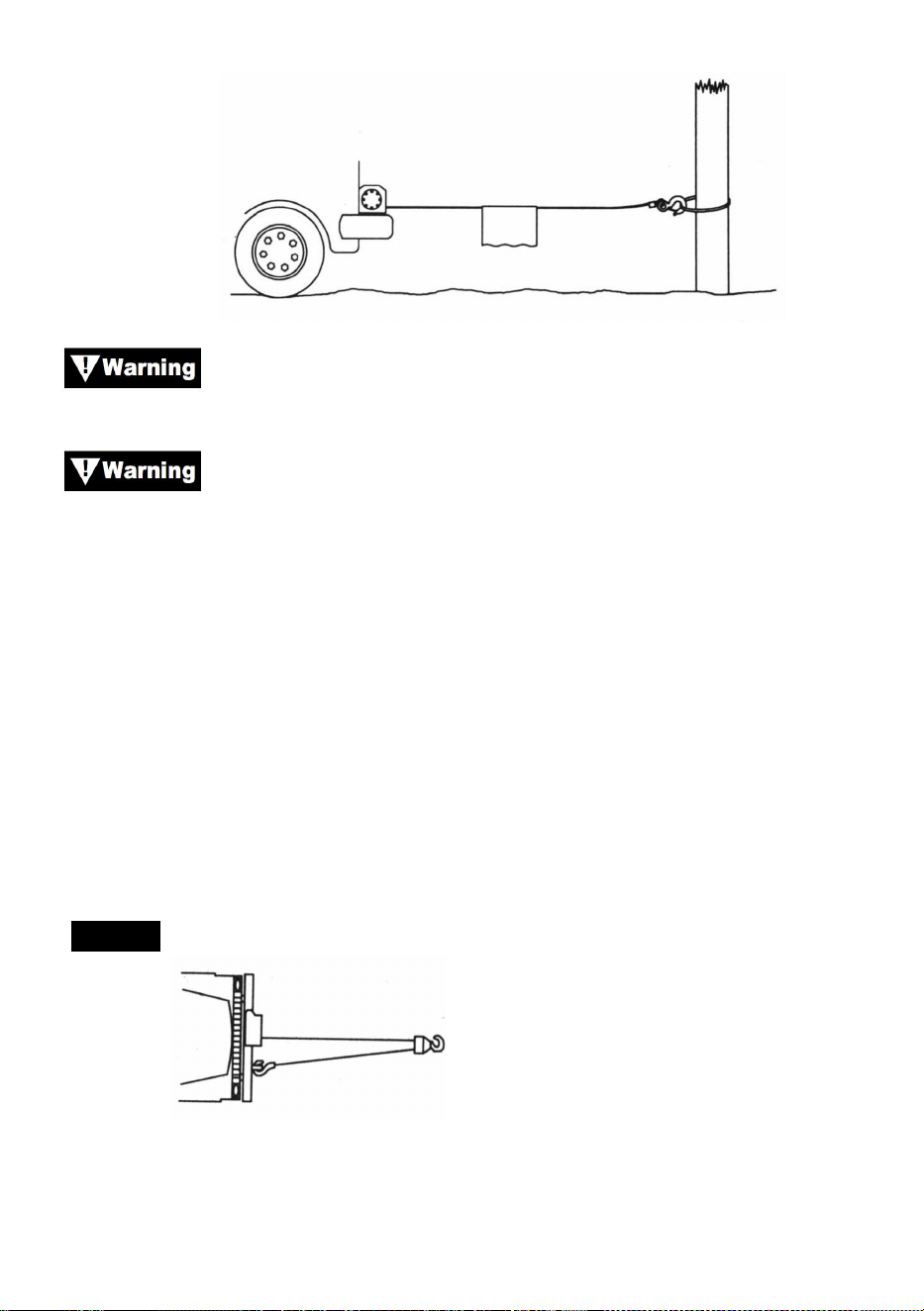
- 24 -
Figuur 14
Let op de nominale capaciteit van de lier en overschrijd deze
niet.
Wanneer de belasting de maximale nominale trekkracht van
de lier overschrijdt, schakelt de externe stroomonderbreker de lier
automatisch uit. Om de stroomonderbreker te resetten, laat u de
schakelaar los. Let op, de lier kan pas weer normaal starten als de
motorwarmte die is opgebouwd door de overmatige belasting is afgekoeld.
1. Dubbele lijn met een katrolblok (zie Afb. 15) om de belasting op de lier,
staalkabel en accu te verminderen. Dubbele voering zal ook de snelheid
van de lierlijn verminderen. Zorg ervoor dat alle gebruikte apparatuur
voldoet aan de maximale lijntreksterkte van de lier. Bij dubbele voering
moeten katrolblokken minimaal twee keer de lijntreksterkte van de lier
hebben.
LIEREN
Figuur 15
1. Als u een trekhaak voor dubbele voering monteert, moet deze aan het
chassis van het voertuig worden bevestigd.

- 25 -
2. Door de lier uit te rusten met een kabelgeleider, wordt slijtage van de
staalkabel tijdens het hijsen onder een hoek verminderd.
3. Trek zo recht mogelijk om ophoping van staaldraad aan één uiteinde van
de trommel te voorkomen.
4. De motor van het voertuig moet draaien tijdens het lieren. Als er veel
wordt gelierd terwijl de motor uit is, is de accu mogelijk te zwak om de
motor opnieuw te starten.
Gebruik een katrolblok om te voorkomen dat u onder scherpe
hoeken liert. Ongelijke lagen veroorzaken ernstige schade aan de lier en
het staaldraad. Dit kan worden gecorrigeerd door de lading vast te zetten,
het staaldraad op te rollen en het aan de andere kant van de trommel te
plaatsen.
Koppel de koppeling niet los onder belasting. Als uw lier is
uitgerust met een vrijloopkoppeling, zorg er dan voor dat er geen spanning
op de staalkabel staat wanneer u de koppeling loskoppelt. Voordat u een
last ophaalt, moet u ervoor zorgen dat de koppeling volledig is
ingeschakeld.
Gebruik de lier om de lading te verplaatsen. Probeer de lier
niet te helpen door het voertuig te verplaatsen. De combinatie van de lier
en het trekken van het voertuig kan de staalkabel overbelasten en de
lading kan de lier breken.
Vertrouw nooit op de lier om een lading op zijn plaats te
houden. Geen van onze lieren is ontworpen voor toepassingen met
ladingsvasthouden en kan losraken of falen door schokbelasting terwijl de
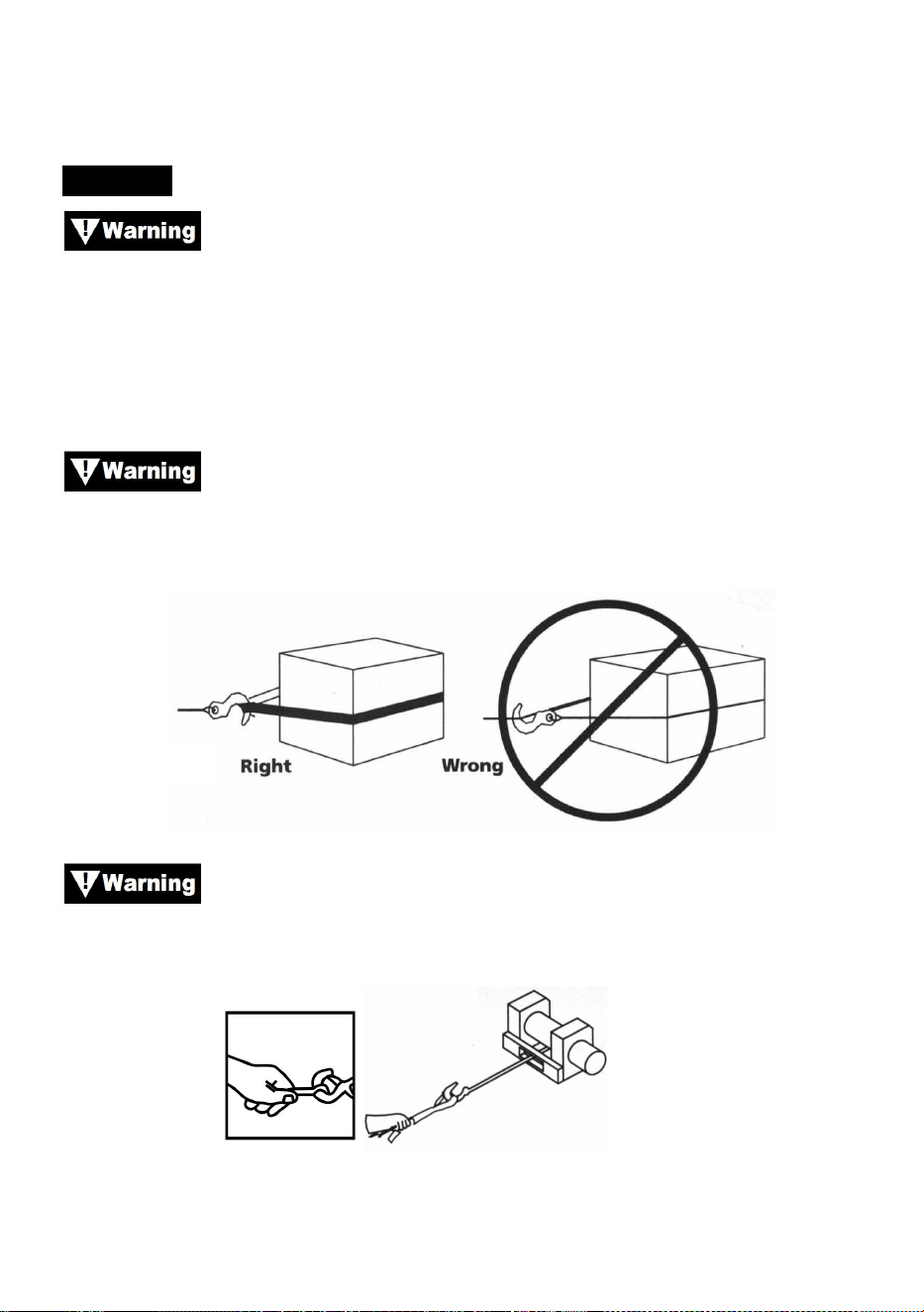
- 26 -
lading wordt getransporteerd. De lading moet op andere manieren worden
vastgezet en de lierhaak moet van de lading worden losgemaakt.
TUIGAGE
Neem de tijd bij het optuigen en neem een redelijke factor
voor veiligheid mee. Onjuiste optuigen kan leiden tot schade aan voertuig
en apparatuur. Het kan ook letsel veroorzaken.
19.Raak nooit de staalkabel of het hijsmateriaal aan terwijl iemand anders
de schakelaar bedient.
20.
Gebruik een nylon sling wanneer u de staalkabel aan een
ankerpunt bevestigt. Bevestig de haak niet terug aan de staalkabel. Dit kan
ervoor zorgen dat de staalkabel breekt.
Figuur 16
Gebruik altijd de handsaver (zie Afb. 17). Houd de haak niet
met uw hand vast. Dit is niet alleen belangrijk bij het oprollen van
staaldraad, maar ook bij het verwijderen van de staaldraad van de lier
onder stroom.
Figuur 17
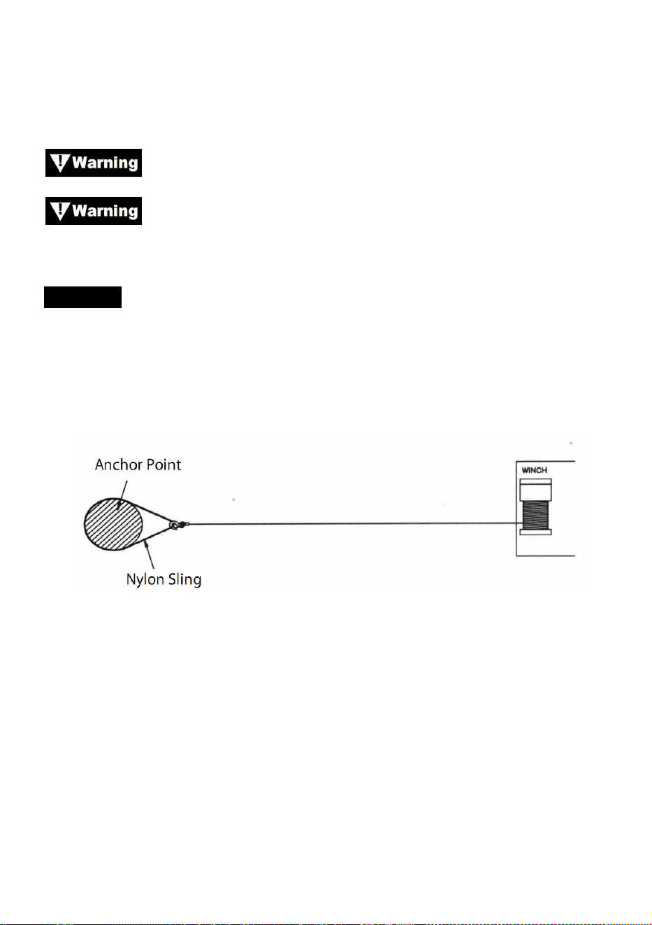
- 27 -
21.Laat de lier met tussenpozen draaien om de slappe staalkabel op te
vangen. Wanneer u een katrolblok gebruikt, zorg er dan voor dat de
staalkabel goed over alle katrollen loopt voordat u een last aanbrengt.
Schakel de koppeling niet opnieuw in terwijl de lier draait.
Bedien de lier altijd met een onbelemmerd zicht op de
lierwerking. Bedek nooit waarschuwings- en instructielabels.
TUIGAGE
3. Afbeelding 18 illustreert de meest gebruikte tuigage. Een nylon sling
wordt gebruikt om de boom te beschermen wanneer deze als anker wordt
gebruikt, en het staaldraad is bevestigd om de sling te gebruiken. Het
gebruik van een ketting of staaldraad wordt afgeraden vanwege schade
die het aan de boom kan toebrengen.
Figuur 18
34. Figuur 19 illustreert een methode van tuigage die wordt gebruikt om
een mechanisch voordeel te verkrijgen. Het gebruik van een katrolblok
verdubbelt bijna de capaciteit van de treklijn. (Let op: het katrolblok is
niet inbegrepen)

- 28 -
Figuur 19
35. Figuur 20 illustreert het gebruik van een katrolblok om de trekrichting te
veranderen. Mechanisch voordeel kan worden verkregen door een
katrolblok met een sluiting aan de nylon strop te bevestigen en de
staalkabel naar het ankerpunt te laten lopen.
Figuur 20
Apparatuur zoals takels, haken, katrollen, banden, etc.
moeten de juiste afmetingen en classificatie hebben en moeten regelmatig
worden gecontroleerd op schade die de sterkte ervan zou kunnen
verminderen.

- 29 -
MAINTAINNENCE
1) Controleer regelmatig de stevigheid van de bevestigingsbouten en
elektrische verbindingen. Verwijder alle vuil of corrosie en houd ze altijd
schoon.
2) Probeer de versnellingsbak niet te demonteren. Reparaties moeten
worden uitgevoerd door de fabrikant of een erkend centrum.
3) De versnellingsbak is gesmeerd met een lithiumvet met hoge
temperatuur en is in de fabriek verzegeld. Er is geen interne smering
vereist.
TROUBLE SHOOTING
Symptomen
Mogelijke oorzaken
Corrigerende maatregelen
Motor werkt niet of alleen
in één richting
1.Schakelaar niet in
werking
2. Gebroken draden of
slechte verbinding
3. Beschadigde motor
1. Vervang schakelaar
2. Controleer op slechte
verbindingen
3. Motor vervangen of repareren
Motor loopt extreem heet
1. Lange operationele
periode
2. mislukt of verwijderd
overbelasting
3. Beschadigde motor
1.laag tot koel
2. Plaats of repareer
overbelasting
3. motor plaatsen of repareren

- 30 -
Motor draait, maar met
onvoldoende vermogen of
lijnsnelheid
1. Zwakke batterij
2. Accu-lierkabel te lang
3. Slechte
batterijverbinding
4.Slechte grond
5. Beschadigde motor
1. Laad de batterij opnieuw op
of vervang deze en controleer
het laadsysteem
2. Houd de lier binnen de
afstand die is toegestaan door
de looddraden
3. Controleer de batterijpolen op
corrosie en maak ze indien
nodig schoon
4. Dek en schone verbindingen
5. motor plaatsen of repareren
Lier loopt achteruit
1.tor draden omgedraaid
2. jeuk draden
omgedraaid
3. De schakelaar is
verkeerd geïnstalleerd
1. Controleer de bedrading
2. Controleer de bedrading
3.eck batterij aansluitingen
Motor draait maar trommel
draait niet
1.Koppeling niet
ingeschakeld
1. Koppeling inschakelen
Lier kusten
1. Overmatige belasting
1. Verminder de belasting of
verdubbel de lijn
Motorische werking maar
stopt
1.
Overbelasting/overbelasti
ng
1. Laat afkoelen

- 31 -


Teknisk Support och e-garanticertifikat www.vevor.com/support
ELEKTRISK VINSCH
MODELL: P2000-1/P3000-1C/P4000-1D/P4000-1W
We continue to be committed to provide you tools with competitive price.
"Save Half", "Half Price" or any other similar expressions used by us only represents an
estimate of savings you might benefit from buying certain tools with us compared to the major
top brands and does not necessarily mean to cover all categories of tools offered by us. You
are kindly reminded to verify carefully when you are placing an order with us if you are
actually saving half in comparison with the top major brands.


- 1 -
MODELL: P2000-1/P3000-1C/P4000-1D/P4000-1W
Have product questions? Need technical support? Please feel free to
contact us:
Technical Support and E-Warranty Certificate
www.vevor.com/support
NEED HELP? CONTACT US!
This is the original instruction, please read all manual instructions
carefully before operating. VEVOR reserves a clear interpretation of our
user manual. The appearance of the product shall be subject to the
product you received. Please forgive us that we won't inform you again if
there are any technology or software updates on our product.
ELECTRIC WINCH
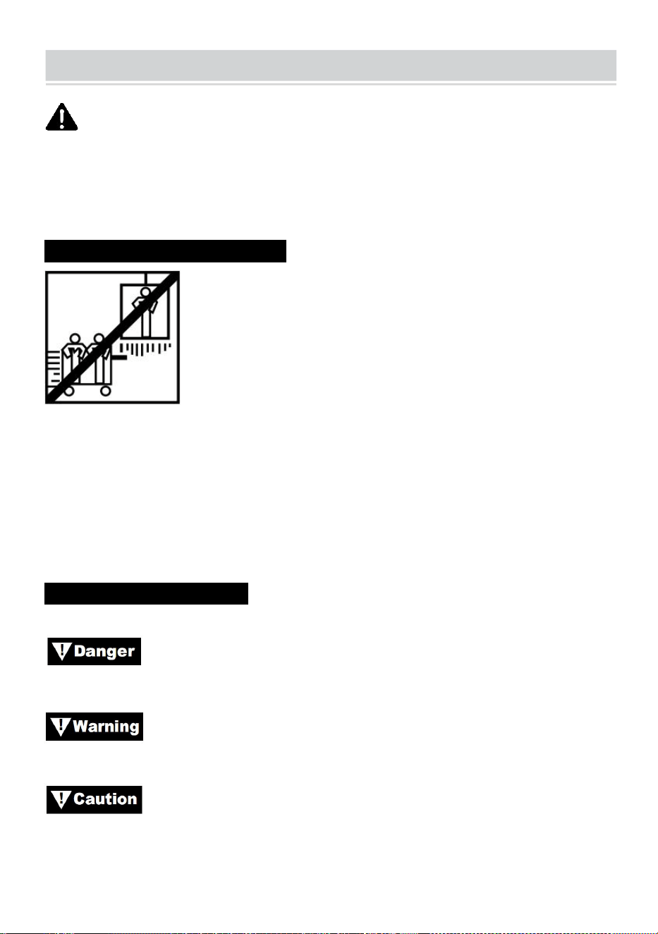
- 2 -
SAFE INSTRUCTIONS
VARNING: Läs noga och förstå alla MONTERINGS- OCH
DRIFTINSTRUKTIONER innan användning. Underlåtenhet att följa
säkerhetsreglerna och andra grundläggande säkerhetsåtgärder kan leda
till allvarliga personskador.
ANSÖKNINGSINFORMATION N
Denna vinsch är designad för att flytta en last på marknivå eller uppför en
sluttning. Den är varken konstruerad eller avsedd för hissning.
Denna vinsch ska inte användas för att lyfta eller flytta människor.
Denna vinsch är avsedd för intermittent användning på grund av
värmeuppbyggnadsegenskaper hos olika komponenter. Om änden av
motorn blir obehagligt varm att röra vid, stoppa vinschningen och låt
motorn svalna.
SÄKERHETSÅTGÄRDER
I denna handbok hittar du noteringar med följande rubriker:
: Indikerar en överhängande farlig situation som, om den inte
undviks, kommer att resultera i dödsfall eller allvarlig skada.
: Indikerar en potentiellt farlig situation som, om den inte
undviks, kan resultera i dödsfall eller allvarlig skada.
: Indikerar en potentiellt farlig situation som, om den inte
undviks, kan resultera i mindre eller måttlig skada. Denna notation
används också för att varna mot osäkra metoder.
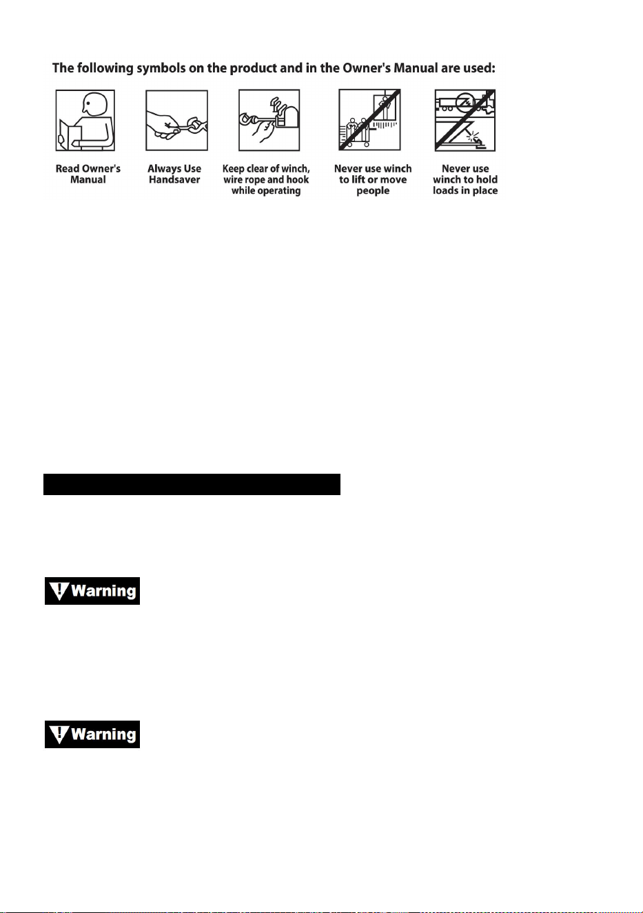
- 3 -
Obs: Indikerar ytterligare information i installations- och
driftprocedurerna för din vinsch.
Observera : Winch är främst designad för intermittenta applikationer.
Denna vinsch är inte konstruerad för att användas i industri- eller
lyftapplikationer.
Använd alltid handsaver på kroken.
Håll dig borta från vinsch, vajer och krok under drift.
Använd aldrig vinsch för att lyfta eller flytta människor.
Använd aldrig vinsch för att hålla laster på plats.
ALLMÄN SÄKERHETSINFORMATION
Din vinsch är en mycket kraftfull maskin. Om det används på ett osäkert
eller felaktigt sätt, det kan resultera i egendomsskada eller personskada.
Ansvaret för säker installation och drift av vinschen och
förhindrande av person- och egendomsskador vilar ytterst på dig,
operatören. Det finns ingen ersättning för att använda gott omdöme och
försiktighet vid manövrering av en vinsch.
Vajern kan gå sönder innan vinschen stannar.
För tunga belastningar, använd en remskiva för att minska belastningen på
stållina.
204. Maximal arbetsbelastningskapacitet är på vajerskiktet närmast
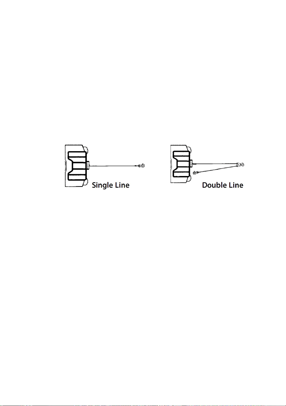
- 4 -
trumman. ÖVERBELASTNING INTE. FÖRSÖK INTE LÅNGT DRAG
VID TUNG LAST. Överbelastningar kan skada vinschen och/eller
vajern och skapa osäkra driftsförhållanden. FÖR LASTNINGAR ÖVER
1/2 NÄRMED KAPACITET REKOMMENDERAR VI ANVÄNDNING
AV DET VALFRIDA DRAGBLOCKEN FÖR ATT DUBBELLINDERA
STADEN(FIGUR 1). Detta minskar belastningen på vinschen och
belastningen på vajern med cirka 50 %. Fäst kroken på den bärande
delen. Fordonets motor bör vara igång under vinschdrift. Om kraftig
vinschning utförs med motorn avstängd kan batteriet vara för svagt för
att starta om motorn.
Figur 1.
205. EFTER ATT LÄST OCH FÖRSTÅTT DENNA MANUAL, LÄR DU
ANVÄNDA DIN VINSCH. Efter att ha installerat vinschen, öva på att
använda den så att du blir bekant med den när behovet uppstår.
206. "Förflytta" INTE ditt fordon för att hjälpa vinschen att dra lasten.
Kombinationen av vinsch och fordon som drar ihop kan överbelasta
vajern och vinschen.
207. STÅ ALLTID FRÅN STÅLRIN, HAKEN OCH VINSCHEN. OM
NÅGON KOMPONENT FEL ÄR DET SOM SANNOLIKLIGA
HÄNDELSER ÄR DET BÄSTA ATT ÄR UTOM SKADA.
208. Inspektera stållinor och utrustning ofta. En sliten stålrep med
trasiga trådar bör bytas ut omedelbart.
209. Använd kraftiga läderhandskar när du hanterar stållinor. Låt inte
vajer glida genom dina händer.
210. Vinscha aldrig med mindre än 5 varv vajer runt vinschtrumman
eftersom vajerändfästet kanske INTE tål full belastning.
211.Stick aldrig fingret genom kroken. Om ditt finger fastnade i kroken kan
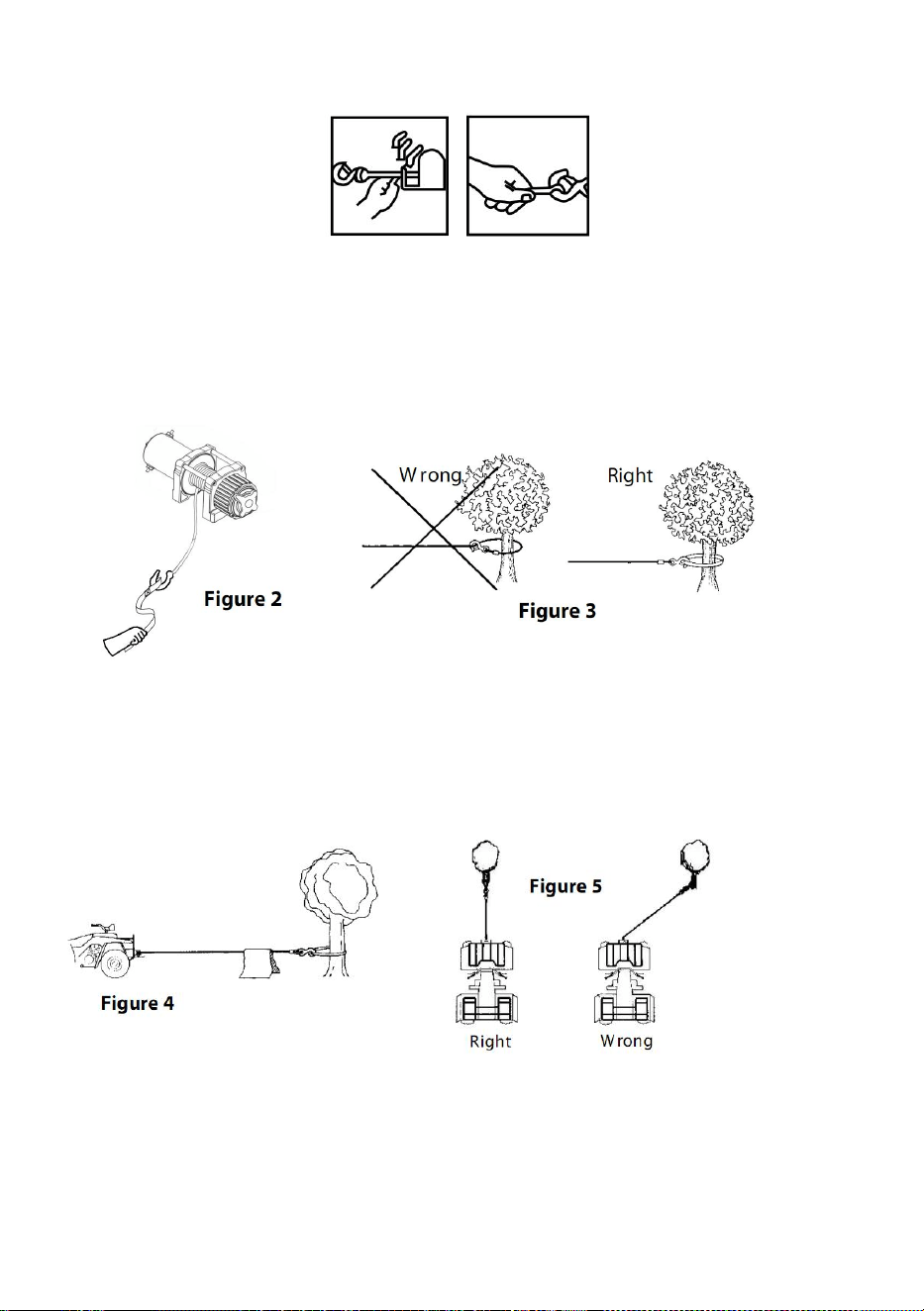
- 5 -
du tappa fingret .
212. ANVÄND ALLTID HANDSPARAREN När du styr in eller ut
stållinan (se figur 2).
213. HAKA ALDRIG TILLBAKA I SIG SJÄLV eftersom du kan skada
vajern. Använd en nylonsele (Figur 3).
214. Det är en bra idé att lägga en tung filt eller jacka över stållinan
nära krokänden när du drar tunga laster (Figur 4). Om ett vajerfel skulle
inträffa kommer duken att fungera som en dämpare och hjälpa till att
förhindra att repet piskar.
215. UNDVIK KONTINUERLIG DRAG FRÅN EXTREMA vinklar
eftersom detta kommer att få stållinan att staplas upp i ena änden av
trumman. Detta kan klämma fast stållinan i vinschen och orsaka skada
på repet eller vinschen.
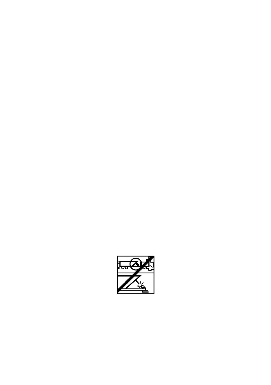
- 6 -
216. Dölj ALDRIG VARNINGSINSTRUKTIONSETIKETTERNA.
217. Använd alltid vinschen med fri sikt över vinschningen.
218. Utrustning som tackel, krokar, remskivor, remmar etc. bör
anpassas till vinschuppgiften och bör regelbundet inspekteras för
skador som kan minska deras styrka.
219. SLOPP ALDRIG FREESPOOL-KOPPLINGEN NÄR DET FINNS
LAST PÅ VINSCHEN.
220. ARBETA ALDRIG PÅ ELLER KRING VINSCHTRUMMAN NÄR
VINSCHEN ÄR UNDER BELASTNING.
221. ANVÄNDA INTE VINSCHEN NÄR UNDER PÅVERKAN AV
DROGER, ALKOHOL ELLER MEDICINER.
222. KOPPLA ALLTID FRÅN VINSCHENS STRÖM TILL BATTERIET
INNAN DU ARBETA I ELLER KRING VINSCHtrumman så att vinschen
inte kan slås på av misstag.
223. När du flyttar en last, ta sakta upp vajerns slack tills den blir spänd.
Stanna, kontrollera alla vinschanslutningar igen. Se till att kroken sitter
ordentligt. Om en nylonsele används, kontrollera infästningen till
lasten.
224. När du använder din vinsch för att flytta en last, placera
fordonsväxellådan i neutralläge, ställ i fordonsbromsen och blockera
alla hjul.
225. ANVÄND INTE VINSCHEN FÖR ATT HÅLLA LASTNINGAR PÅ
PLATS. Använd andra sätt att fästa laster, såsom spännband.
226. ANVÄND ENDAST FABRIKSGODKÄNDA BRYTARE,
FJÄRRKONTROLLER OCH TILLBEHÖR. Användning av icke
fabriksgodkända komponenter kan orsaka person- eller
egendomsskador.
227. MASKINERA ELLER SVETSA INTE NÅGON DEL AV VINSCHEN.
Sådana ändringar kan försvaga vinschens strukturella integritet.

- 7 -
228. ANSLUT INTE VINSCHEN TILL VARKEN 110V AC HUS STRÖM
ELLER 220V NÄTTEN, DÅ VINSCHUTBRÄNDNING ELLER DÖDLIG
STÖT KAN FÖRKOMMA.
229. Tillåt aldrig stötbelastningar på vinsch eller vajer.
230. Var försiktig när du drar eller sänker en last upp och ner för en
ramp eller sluttning. Håll människor, husdjur och egendom borta från
lastens väg.
231. Omkopplarenheten måste hållas fri från smuts och fukt för att
säkerställa säker drift.
232. För att förhindra obehörig användning av vinschen, ta bort
pendelkontrollen och förvara den på ett rent och torrt ställe, såsom
handskfacket.
PRODUCT SPECIFICATION
P2000-1
P3000-1C
P4000-1D
P4000-1W
Spänning
12VDC
12VDC
12VDC
12VDC
Märkeffekt
0,95 hk
1,3 hk
2,2 hk
2,2 hk
Utväxling
153:1
153:1
128,2
:
1
128,2
:
1
Längd på
tråd
1,8 m
1,8 m
1,8 m
1,8 m
Rep
Stål ,
5/32 tum * 39
fot
Stål ,
3/16 tum * 39
fot
Stål ,
1/4 tum * 39 fot
Syntet ,
1/4 tum * 39 fot
IP
R ating
55
55
55
55
Model
SPEC.

- 8 -
Paketets innehåll
P2000-1
P3000-1C
P4000-1D
P4000-1W
Elektrisk
vinsch
1
1
1
1
Kontrollbox
×
1
1
1
Trådlös
fjärrkontroll
×
1
1
1
Handtagsko
ntroll
1
1
1
1
Roller
Fairlead
1
1
1
1
Monteringsf
äste
1
1
1
1
Clevis Hook
1
1
1
1
Röda bandet
1
1
1
1
Skruvsats
1
1
1
1
Manuell
1
1
1
1
Model
Parts
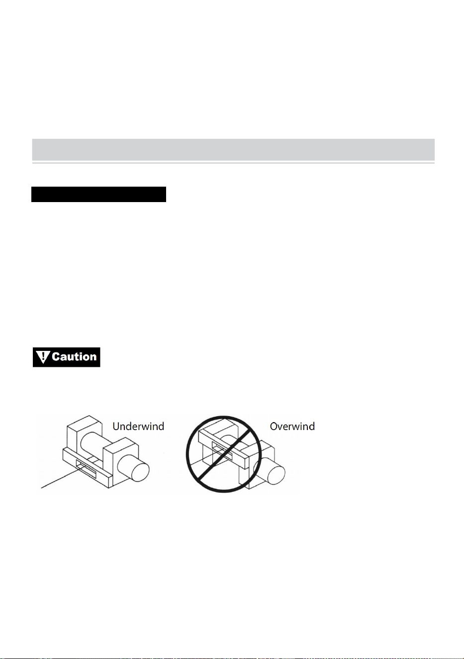
- 9 -
PRODUCT ASSEMBLY INSTRUCTIONS
MONTERA DIN VINSCH
MONTERINGSSATSER
TILLVERKAN REKOMMENDERAR ANVÄNDNING AV EN
MONTERINGSSETT FÖR SÄKER MONTERING PÅ DITT FORDON. ATV
Vinschmonteringssatser ingår normalt i vinschpaketet. Om du väljer att inte
köpa en monteringssats måste din vinsch fästas på en säker och platt
monteringsplats. Observera att din vinsch kanske inte kan användas
säkert utan viss utrustning som ingår i satsen.
Denna vinsch måste monteras med vajern i underlindad
riktning (Figur 6).
Bild 6
Obs: Det är möjligt och inte ovanligt eller avskräckt att montera din vinsch i
andra attityder än de som visas i denna installationsmanual.
Medan monteringssättet är efter eget gottfinnande, kom alltid ihåg att
vinschen ska användas med vajern i en underlindad orientering på
vajertrumman (Figur 1). Din vinsch är konstruerad för att LIPA IN OCH LIPA

- 10 -
UT i en riktning. Försök inte att vända vinschens funktion.
INSTALLATION AV VINSCH
Obs : När du installerar en vinsch kan din installation avvika något från
instruktionerna och diagrammen som följer, beroende på ditt fordon, vinsch,
monteringssats eller konstruktionsstöd.
Innan du påbörjar din vinschinstallation, koppla bort
fordonets jord och pluskablarna från batteriet.
MINIMI ELEKTRISKA KRAV
Se till att välja rätt batteri eller strömförsörjning för att hantera denna vinsch.
Om vinschen används hårt rekommenderas ett hjälpbatteri och en kraftig
generator.
INSTALLATIONSPROCEDUR:
STEG (1)
Installera monteringssats eller förbered en plan, säker monteringsplats för
vinschen för att se till att motorn, trumman och växellådan är korrekt
inriktade. Följ noga instruktionerna som medföljer monteringssatsen.
Se till att det strukturella stödet är tillräckligt starkt för att
stödja vinschens nominella kapacitet.
Obs: Om du inte har en monteringssats måste du borra hål i det
strukturella stödet. Se till att ditt strukturella stöd är minst 3/16” (5 mm)
tjockt.
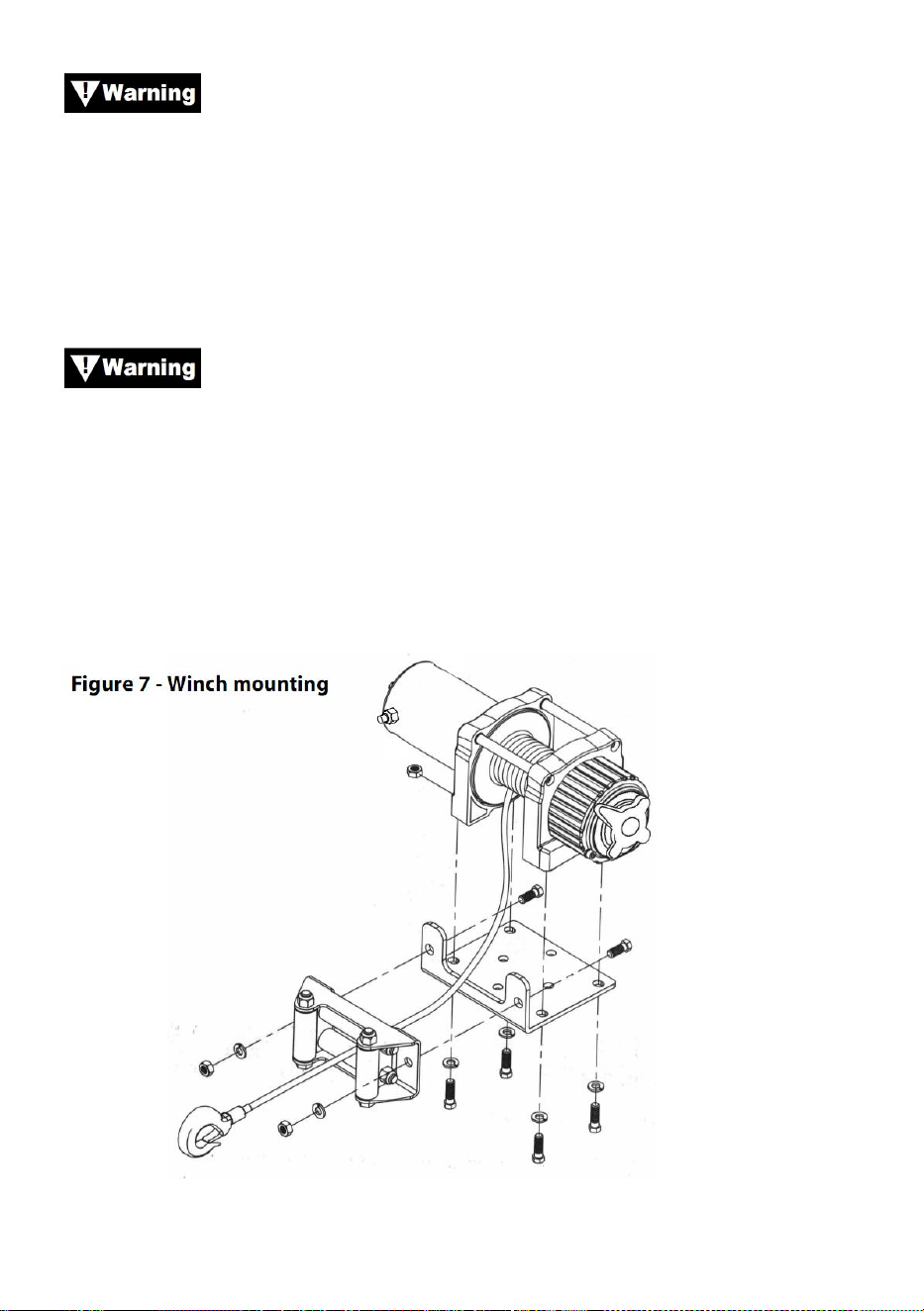
- 11 -
Om bultar, muttrar, brickor och annan hårdvara av olika längd
krävs för din installation, använd alltid hårdvara som motsvarar eller
överstiger hållfasthetsgraden för den medföljande hårdvaran.
Steg ( 2 )
Placera vinschen över hålen i monteringssatsen eller konstruktionsstödet.
När du placerar vinschen, se till att vajern lindas i rätt
rotation på trumman. Underlåtenhet att manövrera vinschen i rätt riktning
kan göra att vinschbromsen (om sådan finns) fungerar felaktigt och/eller att
vinschen går sönder.
Steg (3)
Fäst vinschen (figur 7) till monteringssatsen eller konstruktionsstödet med
bultar, låsbrickor och fyrkantsmuttrar som levereras med vinschen.

- 12 -
Steg (4)
Fäst valsledaren (Figur 7) på monteringsplattan eller strukturstödet med
hjälp av den medföljande hårdvaran eller genom att använda två (2) M8x
20L 8.8 dragstålbultar.
Se till att både monteringsplattan och vinschbeslaget har
dragits åt ordentligt.
Ingen del av fordonet (skidplattor, kablar, extraljus, däck, etc.)
får hindra funktionen av din vinsch. Vid montering, kontrollera alla fordons-
och vinschdelar för fri funktion. Se till att vinschens monteringsplats inte
avsevärt minskar markfrigången.
MONTERING AV MAGNETLÅDA
22. Solenoidboxen kopplar bort din vinsch från batteriet när fordonet är
avstängt.
23. Magnetlådan ska monteras nära batteriet och på en plats som är så
ren och torr som möjligt.
24. Se till att den valda solenoidlådans placering ger tillräckligt avstånd
från alla metallstrukturer, såsom ramrör.
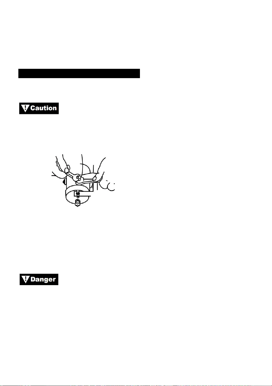
- 13 -
INSTALLATION AV VÄXELBRYTARE
APPLIKATIONER: ATV-SERIEN
När du ansluter kablar till motorn eller slenoidterminalerna,
håll i den inre muttern med en skiftnyckel samtidigt som du drar åt den yttre
muttern med en andra skiftnyckel. Låt inte terminalerna rotera i sina höljen.
Rotation kan orsaka inre trådbrott eller felinriktning av delar (Figur 9).
Figur 9—Korrekt anslutningsåtdragning
Steg (1)
Kontrollera att fordonets jord- och plusledningar från batteriet är
bortkopplade innan du utför något elektriskt arbete.
FÖRSÖK INTE ATT INSTALLERA LEDNINGAR NÄR
BATTERIET ÄR anslutet. Bilbatterier innehåller brandfarliga och explosiva
gaser. Använd ögonskydd under installationen och ta bort alla
metallsmycken. Luta dig inte över batteriet när du gör anslutningar.
Steg (2)
Dra ledningsnätet, fäst ledningsnätet på hårda punkter på fordonet med
buntband.
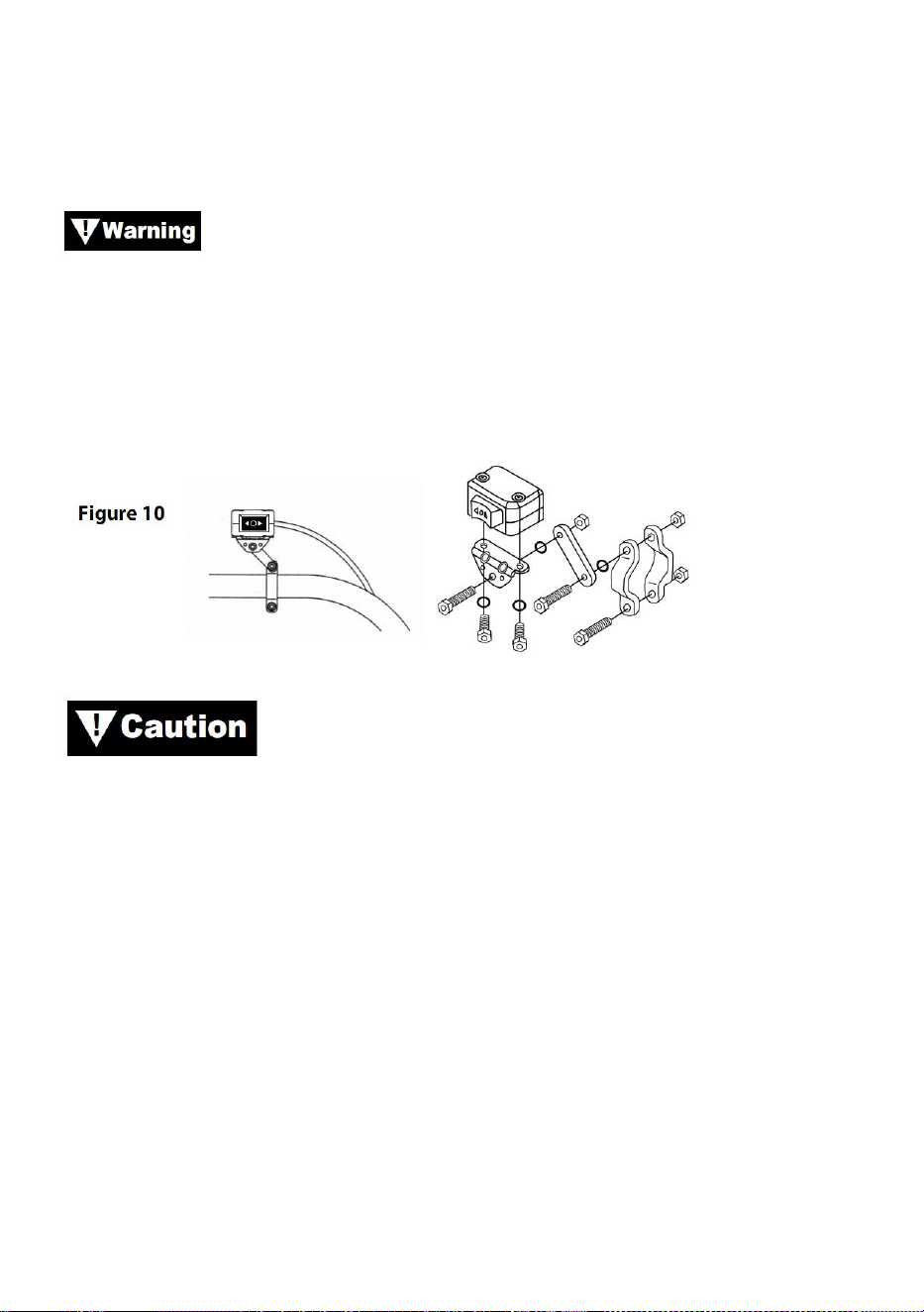
- 14 -
Obs: När du drar kablarna ska lämpliga terminaler placeras nära batteriet,
brytarens monteringspunkt och vinschen. Dina installationskrav kommer
att variera beroende på ditt fordon och din vinsch. Se till att kablarna är
tillräckligt långa för att nå batteriet, byta monteringspunkt och vinsch.
Se till att ledningsnätet inte stör eller kommer i kontakt med
någon het eller rörlig motor, fjädring, styrning, bromsning eller avgasdelar.
Steg(3)
Med hjälp av de medföljande klämmorna, fästet och hårdvarumonteringen
vippströmbrytare på en bekväm plats. Se figur 10.
ANVÄND ALLTID MONTERINGSFÄSTET, SKRUVAR
OCH LÅSMUTTRAR MED VÄXELBRYTARE. Skruvlängderna är
dimensionerade för korrekt penetrering i kopplingsdosan. Överdriven
penetration kan resultera i kortslutningar som kan leda till överhettning av
tråden.
Steg (4)
Det rekommenderas att omkopplaren installeras på det vänstra styret.
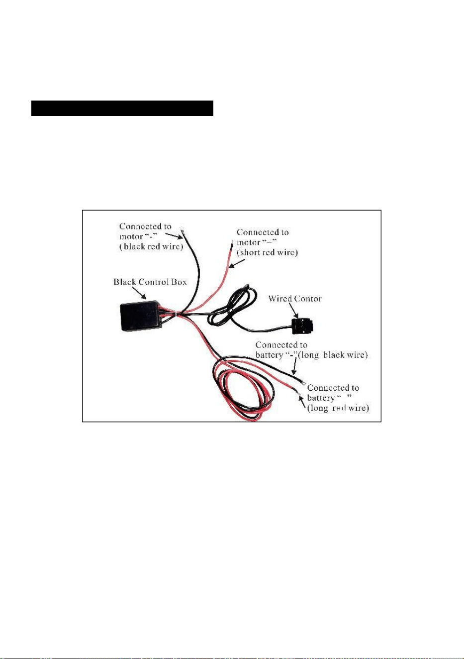
- 15 -
INSTALLATION AV LEDNINGAR
Steg (1)
Dra de korta röda och svarta färgkodade ledningarna till motorn.
Dra de långa röda och svarta färgkodade ledningarna till batteriet.
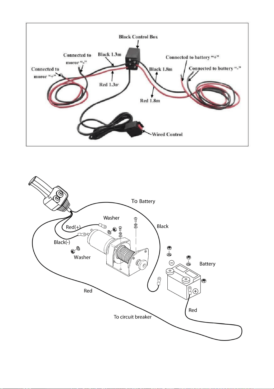
- 16 -

- 17 -
Steg ( 2 )
Kontrollera att alla ledningar är fria från vassa kanter och
klämpunkter.
Fäst lösa kablar med binda eller eltejp.
Lämna aldrig strömbrytaren inkopplad när vinschen inte används.
PRODUCT INSTRUCTIONS
Innan du testar vinschens funktion, se till att rulla av cirka två
fot vajer.
PROVKÖR
15. Dubbelkolla att alla kablar är korrekta och att det inte finns några
exponerade terminaler som kan kortsluta till fordonsramen.
16. Vrid tändningsnyckeln till läget ON. Kontrollera att vinschen fungerar
korrekt.
GRATIS SPOOLDRIFT
Dra och vrid kopplingsvredet till läget "Fri". Om det finns en belastning på
vajern kan det hända att kopplingsvredet inte dras ut lätt. Tvinga INTE
KOPPLINGSVRED. Släpp spänningen på kopplingen genom att jogga ut
en del av vajern. Släpp kopplingen och dra ut vajern och fäst den för att
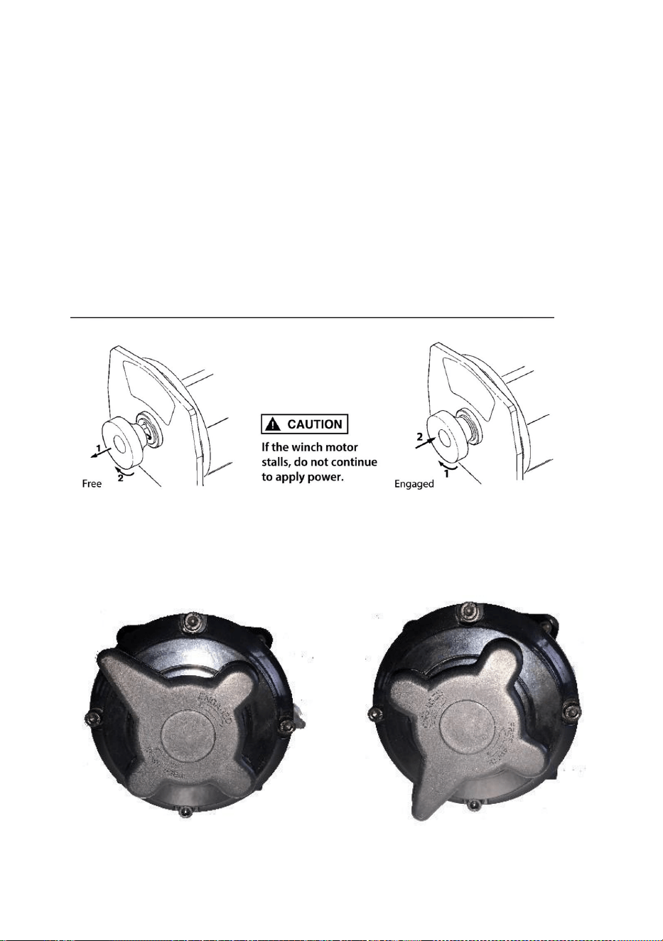
- 18 -
förankra eller last. Kontrollera att det finns minst fem 5 varv av stållina kvar
på trumman. Återkoppla trumman genom att återföra kopplingsvredet till
läget "Inkopplat". Aktivera vinschen i Cable Out tillfälligt för att kontrollera
trummans rotationsriktning. Om trumman roterar åt fel håll, kontrollera dina
kablar igen.
Varning: Vrid kopplingsvredet enligt pilarna och instruktionerna på
den för att koppla in eller lossa vinschväxlarna.
Varning: Kopplingen måste vara helt inkopplad innan vinschning.
Aktivera aldrig kopplingsvredet när trumman vrider sig.
ENGAGERAD: FREESPOOL:

- 19 -
STÅR
36. Vajerns livslängd är direkt relaterad till den vård den får. Vajern på en
ny vinsch, och eventuella ersättningsrep, bör lindas om under en
belastning på minst 100 lb innan vinschen används. Underlåtenhet att
göra detta kommer att resultera i skador på vajer. Inspektera stållinan
före användning. Mosade, klämda, nötta eller krökta områden minskar
kraftigt lastkapaciteten. Byt ut skadad vajer.
37. Förhindra veck innan de uppstår.
(v) Det här är början på en kink. Vid denna tidpunkt bör stållinan rätas ut.
(w) Stållinan drogs och öglan har
spänd till en knäck. Vajern är nu permanent
skadad och bör inte användas.
(x) Resultatet av kinking är att varje tråd drar
en annan mängd som orsakar strängarna under
största spänningen för att bryta och minska
belastningen
vajerns kapacitet.
38. När det är nödvändigt att spola om stållinan utan belastning efter
användning, håll fjärromkopplarkabeln i ena handen och stållinan i den
andra. Börja så långt från fordonet som fjärromkopplaren tillåter,
aktivera strömbrytaren, gå in flera fot rep och släpp strömbrytaren.
Upprepa processen. Släpp alltid omkopplaren innan din hand kommer
inom fyra fot från kabeln (om sådan finns).
39. Se till att stållinan är jämnt och tätt fördelad på trumman. En löst lindad
trumma gör att stållinan kan arbeta sig ner i lagren av stållina på
trumman och bli fastkilad.
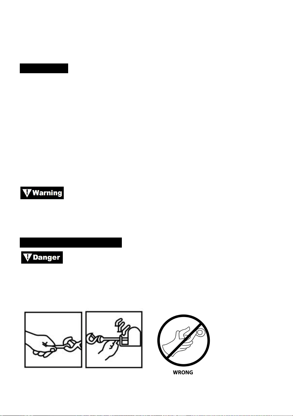
- 20 -
40. Det är inte tillrådligt att smörja eller olja stållinan på grund av
smutsföroreningar som minskar vajerns livslängd.
BYT STADEN
36. Om stållinan har blivit sliten eller börjar visa tecken på att trådar går
sönder måste den bytas ut innan den används igen. För att göra detta,
ta bort det defekta repet genom att spola fritt. Ta bort bulten på
trumman och lossa repet.
37. Sätt i änden av det nya repet och fäst bulten ordentligt.
38. Koppla in kopplingen och rulla tillbaka det nya repet på trumman och
håll spänningen på repet när det rullar. Se till att repet rullar om i
undervindsläget.
Byt endast ut stållinan mot den identiska reservdel som
rekommenderas av tillverkaren.
FÖRBEREDELSER WEINCH
Bär kraftiga läderhandskar när du hanterar stållinor, även
med handskar på. När du hanterar kroken, använd alltid handsaver (se
figur 12.) Stick aldrig in fingrarna i kroken. Att placera fingrar i kroken kan
resultera i skada.
Bild 12
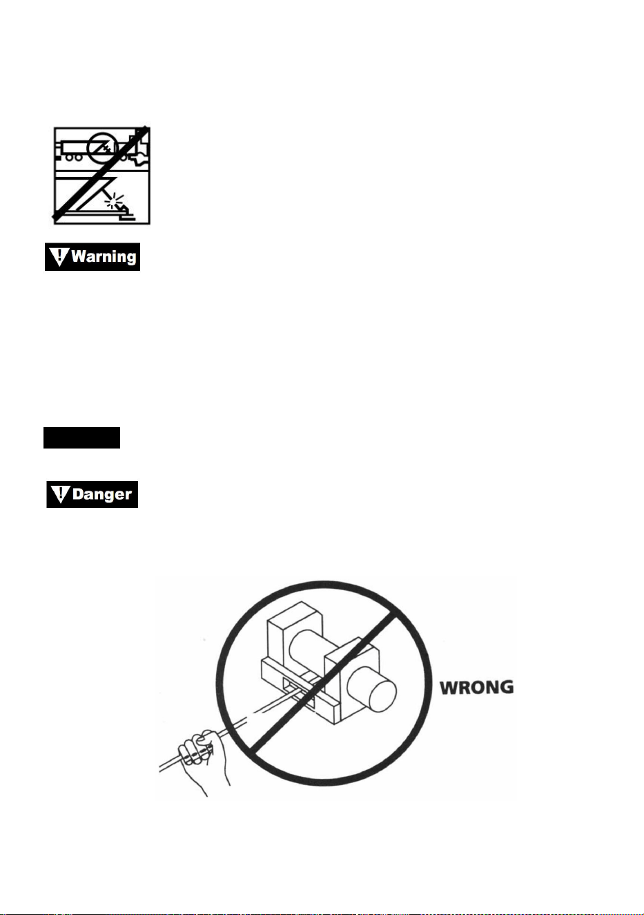
- 21 -
1. När du förankrar det dragande fordonet, dra åt parkeringsbromsen och
blockera eller blockera hjulen. Håll fordonets fotbroms nedtryckt och ställ
automatiska och manuella växellådor i neutralläge.
Inspektera omkopplare och kablar för sprickor, klämda fläckar,
sliten ledning eller lösa anslutningar. En skadad, kortsluten ledning kan
göra att vinschen går så fort den ansluts.
1. När du använder fjärrkontrollen inuti ett fordon ska du alltid föra den
genom ett fönster för att undvika att kabeln klämmer i dörren.
VINCHAR
Rör aldrig vid vajern eller kroken när de är spända eller
belastade. Även i vila kan vinschen ha stållinan i spänning. För aldrig en
stålrep under spänning på trumman med händerna (se fig. 13).
Bild 13
1. Vinsch med minst fem lindningar av stållina runt vinschtrumman. Med
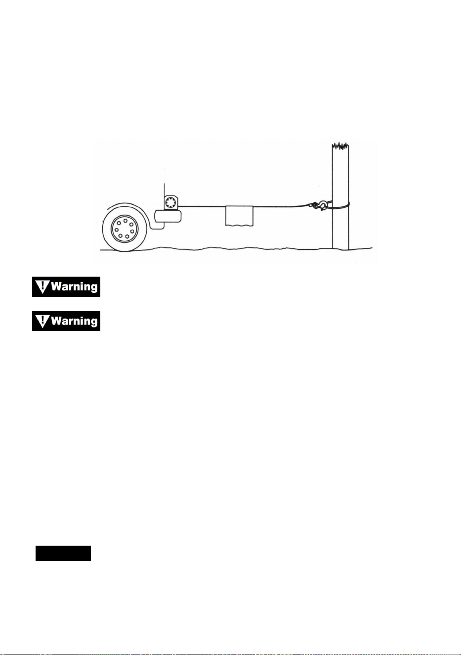
- 22 -
färre lindningar kunde stållinan lossna från trumman under belastning.
2. När du drar en last, placera en filt, jacka eller presenning över vajern
nära krokänden (se Fig. 14). Detta kommer att bromsa tillbaka snäppet av
en trasig vajer och hjälpa till att förhindra allvarliga skador. Höj huven för att
skydda vindrutan.
Bild 14
Notera vinschens nominella kapacitet och överskrid den inte.
När belastningen överstiger vinschens maximala nominella
dragkraft, kommer den externa strömbrytaren automatiskt att stänga av
vinschen. För att återställa strömbrytaren släpper du strömbrytaren.
Observera att vinschen inte kommer att kunna starta om normalt förrän
motorvärmen som byggts upp från överbelastningen har svalnat.
1. Dubbla lina med ett remskivablock (se Fig.15) för att minska
belastningen på vinschen, vajern och batteriet. Dubbla foder kommer
också att minska vinschlinans hastighet. Se till att all utrustning som
används uppfyller vinschens maximala linjedragningsvärde. Vid
dubbelfodring ska remskivorna klassas till minst två gånger vinschens
lindragningsvärde.
VINCHAR
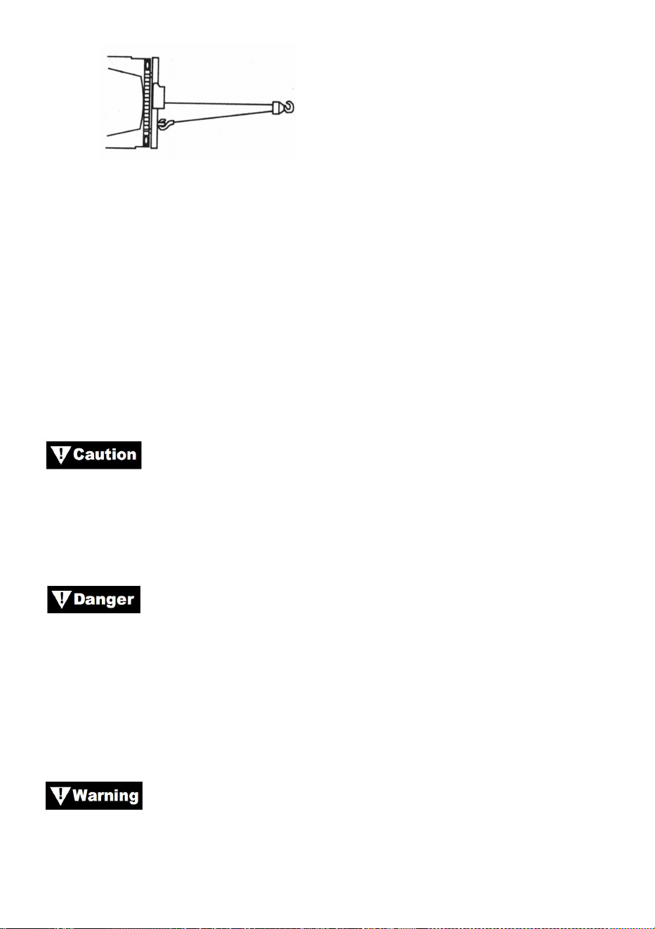
- 23 -
Bild 15
1.Om du installerar en dragkrok för dubbelfoder ska den fästas på
fordonsramen.
2. Att utrusta vinschen med en lina minskar slitaget på vajern vid
vinkeldrag.
3. Dra så rakt som möjligt för att minska ansamlingen av vajer i ena änden
av trumman.
4.Fordonets motor bör vara igång under vinschdrift. Om betydande
vinschning utförs med motorn avstängd kan batteriet vara för svagt för att
starta om motorn.
Använd en remskiva för att undvika vinschning i skarpa
vinklar. Ojämn skiktning kommer att orsaka allvarlig skada på vinschen och
vajern. Om kan korrigeras genom att säkra lasten, rulla ut vajern och flytta
den till motsatta änden av trumman.
Koppla inte ur kopplingen under belastning, om din vinsch är
utrustad med en frispolskoppling, se till att det inte finns någon spänning
på vajern när du kopplar ur kopplingen. Innan du vinschar en last, se till att
kopplingen är helt inkopplad.
Använd vinschen för att flytta lasten. Försök inte hjälpa
vinschen genom att flytta fordonet. Kombinationen av vinschen och
fordonets dragning kan överbelasta stållinan och lasten kan bryta
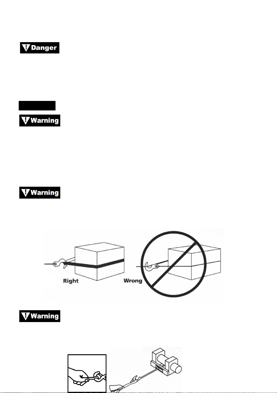
- 24 -
vinschen.
Lita aldrig på att vinschen håller en last på plats. Ingen av
våra vinschar är konstruerade för lasthållande applikationer och kan varva
ner eller misslyckas på grund av stötbelastning när lasten transporteras.
Lasten ska säkras på annat sätt och vinschkroken lossas från lasten.
TACKLING
Ta dig tid när du riggar och inkludera en rimlig faktor för
säkerheten. Felaktig riggning kan leda till skador på fordon och utrustning.
Det kan också orsaka skada.
22.Hantera aldrig vajern eller riggen medan någon annan är vid
kontrollbrytaren.
23.
Använd en nylonslinga när du fäster vajern i en ankarpunkt.
Sätt inte tillbaka kroken på stållinan. Om du gör det kan stållinan gå
sönder.
Bild 16
Använd alltid handspararen (se bild 17). Håll inte i kroken
med handen. Detta är viktigt inte bara när man rullar in vajer utan även när
man tar bort vajern från vinschen under kraft.
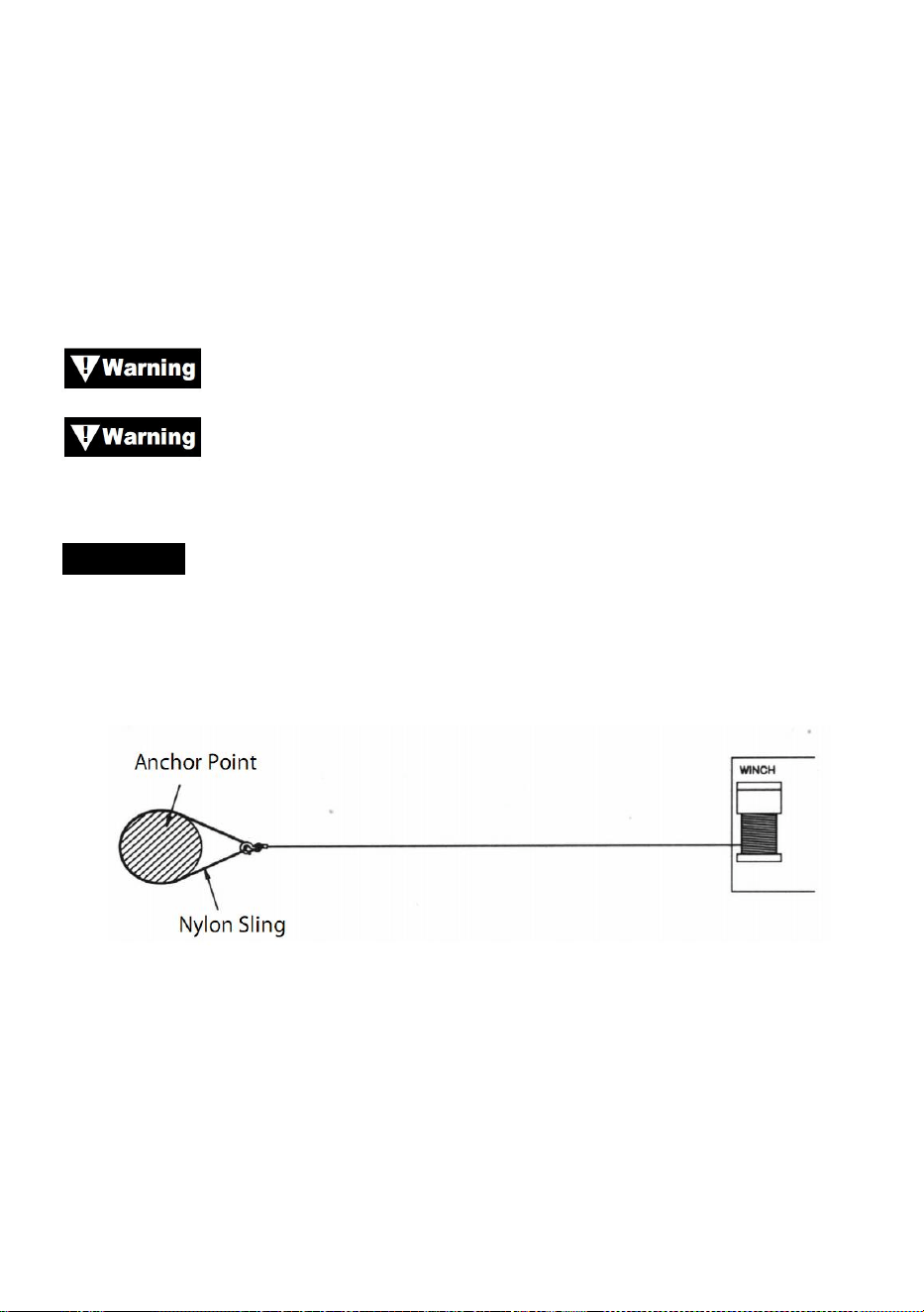
- 25 -
Bild 17
24.Kör vinschen intermittent för att ta upp slak i vajern. När du använder ett
remskiva, se till att vajern löper ordentligt i alla remskivor innan du
applicerar en belastning.
Återkoppla inte kopplingen när vinschen är igång.
Använd alltid vinschen med fri sikt över vinschoperationen.
Dölj aldrig varnings- och instruktionsetiketter.
TACKLING
3. Figur 18 visar den vanligaste riggen. En nylonslinga används för att
skydda trädet när det används som ankare, och stållinan fästs för att
använda selen. Användning av kedja eller stållina rekommenderas inte på
grund av skador som det kan orsaka på trädet.
Bild 18
39. Figur 19 visar en riggningsmetod som används för att erhålla en
mekanisk fördel. Användningen av ett remskiva block fördubblar
nästan draglinans kapacitet. (Observera att remskivan inte ingår)
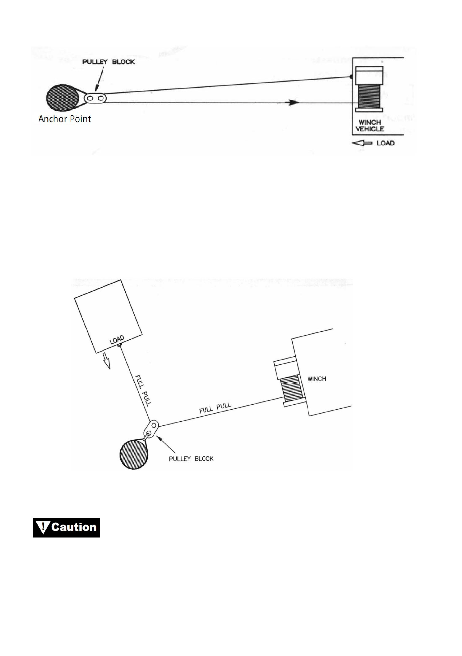
- 26 -
Bild 19
40. Figur 20 illustrerar användningen av ett remskivablock för att ändra
dragriktningen. Mekaniska fördelar kan erhållas genom att fästa en
remskiva på nylonslingan med en bygel och föra vajern till
förankringspunkten.
Bild 20
Utrustning såsom redskap, krokar, remskivor, remmar, etc.
bör vara rätt dimensionerade och klassade och bör inspekteras
regelbundet för skador som kan minska deras styrka.

- 27 -
MAINTAINNENCE
1) Kontrollera regelbundet att monteringsbultar och elektriska
anslutningar är åtdragna. Ta bort all smuts eller korrosion och håll alltid
rent.
2) Försök inte att ta isär växellådan. Reparationer bör utföras av
tillverkaren eller ett auktoriserat center.
3) Växellådan har smords med ett högtemperaturlitiumfett och är
förseglad på fabriken. Ingen intern smörjning krävs.
TROUBLE SHOOTING
Symtom
Möjliga orsaker
Korrigerande åtgärd
Motorn fungerar inte eller
bara i en riktning
1.Switch fungerar inte
2. Trasiga ledningar eller
dålig anslutning
3. Skadad motor
1. Byt omkopplare
2. Kontrollera om det finns
dåliga anslutningar
3. Byt ut eller reparera motorn
Motorn går extremt varm
1.Lång driftperiod
2.misslyckades eller togs
bort
överbelastning
3. Skadad motor
1.låg för att svalna
2.placera eller reparera
överbelastning
3.placera eller reparera motorn

- 28 -
Motorn går, men med
otillräcklig kraft eller
linjehastighet
1.Svagt batteri
2. Batteri till vinschvajern
för lång
3. Dålig batterianslutning
4.Dålig mark
5. Skadad motor
1. Ladda eller byt ut batteriet
och kontrollera
laddningssystemet
2. Håll vinschen inom det
avstånd som tillåts av
ledningstrådar
3. Kontrollera batteripolerna för
korrosion och rengör vid behov
4. Kontrollera och rengör
anslutningarna
5.placera eller reparera motorn
Vinschen går bakåt
1.tor ledningar omvända
2.kliar trådarna omvända
3.Terryomkopplaren är
felaktigt installerad
1. heck ledningar
2.kontrollera kablarna
3. Kontrollera
batterianslutningar
Motorn går men trumman
snurrar inte
1.Kopplingen inte
inkopplad
1. Lägg i kopplingen
Vinsch kuster
1. Överdriven belastning
1. Minska belastningen eller
dubbel linje
Motorn går men stannar
1.Överbelastning/överbel
astning
1.Låt svalna

- 29 -