Quick Start Guide
ABACUS
Analog Music Computer for Eurorack
V 2.0
2 ABACUS Quick Start Guide 3
7. Verwenden Sie nur
spezizierte Wagen,
Ständer, Stative,
Halterungen oder Tische.
Achten Sie darauf, beim
Bewegen der Wagen-
Geräte-Kombination ein
Umkippen zu vermeiden.
8. Vermeiden Sie die Installation in beengten Räumen
wie Bücherregalen.
9. Nicht in der Nähe von oenen Flammenquellen
platzieren, wie brennende Kerzen.
10. Betriebstemperaturbereich von 5° bis 45°C
(41° bis 113°F).
HAFTUNGSAUSSCHLUSS
Music Tribe übernimmt keine Haftung für Verluste,
die Personen entstanden sind, die sich ganz oder
teilweise auf hier enthaltene Beschreibungen,
Fotos oder Aussagen verlassen haben. Technische Daten,
Erscheinungsbild und andere Informationen können
ohne vorherige Ankündigung geändert werden. Alle
Warenzeichen sind Eigentum der jeweiligen Inhaber.
Midas, Klark Teknik, Lab Gruppen, Lake, Tannoy,
Turbosound, TC Electronic, TC Helicon, Behringer, Bugera,
Aston Microphones und Coolaudio sind Warenzeichen
oder eingetragene Warenzeichen der Music Tribe Global
Brands Ltd. © Music Tribe Global Brands Ltd. 2024 Alle
Rechte vorbehalten.
BESCHRÄNKTE GARANTIE
Die geltenden Garantiebedingungen und zusätzliche
Informationen bezüglich der von Music Tribe gewährten
beschränkten Garantie nden Sie online unter
community.musictribe.com/support.
(PT) Instruções de Seguranç
Importantes
1. Por favor, leia e siga todas as instruções.
2. Mantenha o aparelho longe da água, exceto para
produtos destinados ao uso externo.
3. Limpe apenas com um pano seco.
4. Não bloqueie nenhuma abertura de ventilação. Instale
de acordo com as instruções do fabricante.
5. Não instale próximo a fontes de calor, como
radiadores, grelhas de calor, fogões ou outros aparelhos
(incluindo amplicadores) que gerem calor.
6. Use apenas acessórios especicados pelo fabricante.
7. Use apenas carrinhos,
suportes, tripés, suportes
ou mesas especicados.
Tenha cuidado para evitar
tombamentos ao mover a
combinação carrinho/
aparelho.
8. Evite instalar em espaços connados, como estantes.
9. Não coloque perto de fontes de chama nua,
como velas acesas.
10. Intervalo de temperatura de operação de 5° a 45°C
(41° a 113° F).
LEGAL RENUNCIANTE
O Music Tribe não se responsabiliza por perda
alguma que possa ser sofrida por qualquer pessoa
que dependa, seja de maneira completa ou parcial,
de qualquer descrição, fotograa, ou declaração
aqui contidas. Dados técnicos, aparências e outras
informações estão sujeitas a modicações sem aviso
prévio. Todas as marcas são propriedade de seus
respectivos donos. Midas, Klark Teknik, Lab Gruppen,
Lake, Tannoy, Turbosound, TC Electronic, TC Helicon,
Behringer, Bugera, Aston Microphones e Coolaudio
são marcas ou marcas registradas do Music Tribe
Global Brands Ltd. © Music Tribe Global Brands Ltd.
2024 Todos direitos reservados.
GARANTIA LIMITADA
Para obter os termos de garantia aplicáveis e condições e
informações adicionais a respeito da garantia limitada do
Music Tribe, favor vericar detalhes na íntegra através do
website community.musictribe.com/support.
(IT) Istruzioni di sicurezza importanti
1. Per favore, leggere e seguire tutte le istruzioni.
2. Mantenere l'apparecchio lontano dall'acqua, tranne
per i prodotti destinati all'uso all'aperto.
3. Pulire solo con un panno asciutto.
4. Non ostruire alcuna apertura di ventilazione. Installare
in conformità alle istruzioni del produttore.
5. Non installare vicino a fonti di calore come
termosifoni, bocchette di calore, fornelli o altri apparecchi
(compresi gli amplicatori) che producono calore.
6. Utilizzare solo accessori specicati dal produttore.
7. Usare solo carrelli,
supporti, treppiedi, stae
o tavoli specicati. Prestare
attenzione per evitare il
ribaltamento durante lo
spostamento della
combinazione carrello/
apparecchio.
8. Evitare l'installazione in spazi connati come librerie.
9. Non posizionare vicino a fonti di amma nude,
come candele accese.
10. Intervallo di temperatura di funzionamento da
5° a 45°C (41° a 113°F).
DISCLAIMER LEGALE
Music Tribe non si assume alcuna responsabilità per
eventuali danni che possono essere subiti da chiunque
si adi in tutto o in parte a qualsiasi descrizione,
fotograa o dichiarazione contenuta qui. Speciche
tecniche, aspetti e altre informazioni sono soggette
a modiche senza preavviso. Tutti i marchi sono di
proprietà dei rispettivi titolari. Midas, Klark Teknik,
Lab Gruppen, Lake, Tannoy, Turbosound, TC Electronic,
TC Helicon, Behringer, Bugera, Aston Microphones e
Coolaudio sono marchi o marchi registrati di Music Tribe
Global Brands Ltd. © Music Tribe Global Brands Ltd.
2024 Tutti i diritti riservati.
GARANZIA LIMITATA
Per i termini e le condizioni di garanzia applicabili e le
informazioni aggiuntive relative alla garanzia limitata
di Music Tribe, consultare online i dettagli completi su
community.musictribe.com/support.
(NL) Belangrijke
veiligheidsvoorschriften
1. Lees alsjeblieft alle instructies en volg deze op.
2. Houd het apparaat uit de buurt van water, behalve
voor producten die bedoeld zijn voor buitengebruik.
3. Reinig alleen met een droge doek.
4. Blokker geen ventilatieopeningen. Installeer volgens
de instructies van de fabrikant.
5. Installeer niet in de buurt van warmtebronnen
zoals radiatoren, warmte registers, fornuizen of andere
apparaten (inclusief versterkers) die warmte produceren.
6. Gebruik alleen accessoires die door de fabrikant
zijn gespeciceerd.
7. Gebruik alleen
gespeciceerde karren,
standaards, statieven,
beugels of tafels. Wees
voorzichtig om kantelen te
voorkomen bij het
verplaatsen van de kar/
apparaatcombinatie.
8. Vermijd installatie in afgesloten ruimtes
zoals boekenkasten.
9. Plaats niet in de buurt van naakte vlambronnen,
zoals brandende kaarsen.
10. Bedrijfstemperatuurbereik
van 5° tot 45°C (41° tot 113°F).
WETTELIJKE ONTKENNING
Music Tribe aanvaardt geen aansprakelijkheid voor enig
verlies dat kan worden geleden door een persoon die
geheel of gedeeltelijk vertrouwt op enige beschrijving,
foto of verklaring hierin. Technische specicaties,
verschijningen en andere informatie kunnen zonder
voorafgaande kennisgeving worden gewijzigd. Alle
handelsmerken zijn eigendom van hun respectievelijke
eigenaren. Midas, Klark Teknik, Lab Gruppen, Lake,
Tannoy, Turbosound, TC Electronic, TC Helicon,
Behringer, Bugera, Aston Microphones en Coolaudio
(EN) Safety Instruction
1. Please read and follow all instructions.
2. Keep the apparatus away from water, except for
outdoor products.
3. Clean only with a dry cloth.
4. Do not block any ventilation openings. Install in
accordance with the manufacturer’s instructions.
5. Do not install near any heat sources such as radiators,
heat registers, stoves or other apparatus (including
ampliers) that produce heat.
6. Use only attachments/accessories specied by
the manufacturer.
7. Use only specied
carts, stands, tripods,
brackets, or tables. Use
caution to prevent tip-over
when moving the cart/
apparatus combination.
8. Avoid installing in conned spaces like bookcases.
9. Do not place near naked ame sources, such as
lighted candles.
10. Operating temperature range 5° to 45°C
(41° to 113°F).
LEGAL DISCLAIMER
Music Tribe accepts no liability for any loss which may
be suered by any person who relies either wholly or in
part upon any description, photograph, or statement
contained herein. Technical specications, appearances
and other information are subject to change without
notice. All trademarks are the property of their
respective owners. Midas, Klark Teknik, Lab Gruppen,
Lake, Tannoy, Turbosound, TC Electronic, TC Helicon,
Behringer, Bugera, Aston Microphones and Coolaudio
are trademarks or registered trademarks of Music
Tribe Global Brands Ltd. © Music Tribe Global Brands
Ltd. 2024 All rights reserved.
LIMITED WARRANTY
For the applicable warranty terms and conditions
and additional information regarding Music Tribe’s
Limited Warranty, please see complete details online at
community.musictribe.com/support.
(ES) Instrucción de seguridad
1. Por favor, lea y siga todas las instrucciones.
2. Mantenga el aparato alejado del agua, excepto para
productos destinados al uso en exteriores.
3. Limpie solo con un paño seco.
4. No bloquee ninguna abertura de ventilación. Instale
de acuerdo con las instrucciones del fabricante.
5. No instale cerca de fuentes de calor como radiadores,
registros de calor, estufas u otros aparatos (incluyendo
amplicadores) que generen calor.
6. Utilice solo accesorios especicados por el fabricante.
7. Use solo carros,
soportes, trípodes,
soportes o mesas
especicados. Tenga
precaución para evitar el
vuelco al mover la
combinación carro/
aparato.
8. Evite la instalación en espacios connados
como estanterías.
9. No colocar cerca de fuentes de llama desnuda,
como velas encendidas.
10. Rango de temperatura de funcionamiento de
5° a 45°C (41° a 113° F).
NEGACIÓN LEGAL
Music Tribe no admite ningún tipo de responsabilidad
por cualquier daño o pérdida que pudiera sufrir
cualquier persona por conar total o parcialmente en la
descripciones, fotografías o armaciones contenidas en
este documento. Las especicaciones técnicas, imágenes
y otras informaciones contenidas en este documento
están sujetas a modicaciones sin previo aviso. Todas las
marcas comerciales que aparecen aquí son propiedad
de sus respectivos dueños. Midas, Klark Teknik,
Lab Gruppen, Lake, Tannoy, Turbosound, TC Electronic,
TC Helicon, Behringer, Bugera, Aston Microphones y
Coolaudio son marcas comerciales o marcas registradas
de Music Tribe Global Brands Ltd. © Music Tribe Global
Brands Ltd. 2024 Reservados todos los derechos.
GARANTÍA LIMITADA
Si quiere conocer los detalles y condiciones aplicables
de la garantía así como información adicional sobre
la Garantía limitada de Music Tribe, consulte online
toda la información en la web community.musictribe.
com/support.
(FR) Consignes de sécurité
1. Veuillez lire et suivre toutes les instructions.
2. Gardez l'appareil éloigné de l'eau, sauf pour les
produits destinés à une utilisation en extérieur.
3. Nettoyez uniquement avec un chion sec.
4. Ne bloquez aucune ouverture de ventilation. Installez
conformément aux instructions du fabricant.
5. N'installez pas près de sources de chaleur telles
que radiateurs, grilles de chaleur, cuisinières ou autres
appareils (y compris les amplicateurs) qui produisent de
la chaleur.
6. Utilisez uniquement les accessoires spéciés par
le fabricant.
7. Utilisez uniquement
des chariots, des supports,
des trépieds, des supports
ou des tables spéciés.
Faites attention pour éviter
le renversement lors du
déplacement de la
combinaison chariot/
appareil.
8. Évitez l'installation dans des espaces connés comme
les bibliothèques.
9. Ne pas placer près de sources de amme nue,
telles que des bougies allumées.
10. Plage de température de fonctionnement de
5° à 45°C (41° à 113°F)
DÉNI LÉGAL
Music Tribe ne peut être tenu pour responsable pour
toute perte pouvant être subie par toute personne
se ant en partie ou en totalité à toute description,
photographie ou armation contenue dans ce
document. Les caractéristiques, l’apparence et d’autres
informations peuvent faire l’objet de modications
sans notication. Toutes les marques appartiennent
à leurs propriétaires respectifs. Midas, Klark Teknik,
Lab Gruppen, Lake, Tannoy, Turbosound, TC Electronic,
TC Helicon, Behringer, Bugera, Aston Microphones et
Coolaudio sont des marques ou marques déposées de
Music Tribe Global Brands Ltd. © Music Tribe Global
Brands Ltd. 2024 Tous droits réservés.
GARANTIE LIMITÉE
Pour connaître les termes et conditions de
garantie applicables, ainsi que les informations
supplémentaires et détaillées sur la Garantie
Limitée de Music Tribe, consultez le site Internet
community.musictribe.com/support.
(DE) Wichtige Sicherheitshinweise
1. Bitte lesen Sie alle Anweisungen sorgfältig durch und
befolgen Sie diese.
2. Halten Sie das Gerät von Wasser fern, außer für
Produkte, die für den Außeneinsatz vorgesehen sind.
3. Reinigen Sie es nur mit einem trockenen Tuch.
4.
Blockieren Sie keine Belüftungsönungen. Installieren
Sie gemäß den Anweisungen des Herstellers.
5. Installieren Sie nicht in der Nähe von Wärmequellen
wie Heizkörpern, Heizregistern, Öfen oder anderen
Geräten (einschließlich Verstärkern), die Wärme erzeugen.
6. Verwenden Sie nur Zubehörteile, die vom Hersteller
angegeben sind.
4 ABACUS Quick Start Guide 5
(CN)
安全须知
1. 请阅读, 保存, 遵守所有的说明, 注意所
有的警示。
2. 请勿在靠近水的地方使用本产品。
3. 请用干布清洁本产品。
4. 请只使用厂家指定的附属设备和配件。
不要堵塞任何通风口。按照制造商的说明
进行安装。
5. 请只使用厂家指
定的或随货销售的
手推车, 架子, 三角
架, 支架和桌子等。
若使用手推车来搬
运设备, 请注意安
全放置设备, 以避
免手推车和设备倾
倒而受伤。
6. 请勿安装在密闭空间, 如书柜或类似
装置。
7. 请勿将本产品安装在热源附近, 如暖气
片, 炉子或其它产生热量的设备 (包括功放
器)。 产品上不要放置裸露的火焰源, 如点
燃的蜡烛。
8. 如果液体流入或异物落入设备内,
设备遭雨淋或受潮, 设备不 能正常运作或
被摔坏等, 设备受损需进行维修时, 所有维
修均须由 合格的维修人员进行维修。
法律声明
对于任何因在此说明书提到的全部或部份
描述、 图片或声明而造成的损失, Music Tribe
不负任何责任。 技术参数和外观若有更改,
恕不另行通知。 所有的商标均为其各自所
有者的财产。
Midas, Klark Teknik, Lab Gruppen,
Lake, Tannoy, Turbosound, TC Electronic, TC Helicon,
Behringer, Bugera, Aston Microphones
和 Coolaudio
是 Music Tribe Global Brands Ltd. 公司的商标
或注册商标。 © Music Tribe Global Brands Ltd.
2024 版权所有。
保修条款
有关音乐集团保修的适用条款及其它相关
信息, 请登陆 community.musictribe.com/support
网站查看完整的详细信息。
zijn handelsmerken of gedeponeerde handelsmerken
van Music Tribe Global Brands Ltd. © Music Tribe Global
Brands Ltd. 2024 Alle rechten voorbehouden.
BEPERKTE GARANTIE
Voor de toepasselijke garantievoorwaarden en
aanvullende informatie met betrekking tot de beperkte
garantie van Music Tribe, zie de volledige details online
op community.musictribe.com/support.
(SE) Viktiga säkerhetsanvisningar
1. Vänligen läs och följ alla instruktioner noggrant.
2. Håll apparaten borta från vatten, förutom
för utomhusprodukter.
3. Rengör endast med en torr trasa.
4. Blockera inte några ventilationsöppningar.
Installera enligt tillverkarens anvisningar.
5. Installera inte nära några värmekällor som element,
värmeregistrar, spisar eller andra apparater (inklusive
förstärkare) som genererar värme.
6. Använd endast tillbehör som anges av tillverkaren.
7. Använd endast
specicerade vagnar, ställ,
stativ, fästen eller bord. Var
försiktig för att undvika att
vagnen/
apparatkombinationen
tippar när den yttas.
8. Undvik installation i
trånga utrymmen som bokhyllor.
9. Placera inte nära öppen låga, såsom tända ljus.
10. Driftstemperaturområde 5° till 45°C (41° till 113°F).
FRISKRIVNINGSKLAUSUL
Music Tribe tar inget ansvar för någon förlust som kan
drabbas av någon person som helt eller delvis förlitar
sig på någon beskrivning, fotogra eller uttalande som
nns här. Tekniska specikationer, utseenden och annan
information kan ändras utan föregående meddelande.
Alla varumärken tillhör respektive ägare. Midas,
Klark Teknik, Lab Gruppen, Lake, Tannoy, Turbosound,
TC Electronic, TC Helicon, Behringer, Bugera, Aston
Microphones och Coolaudio är varumärken eller
registrerade varumärken som tillhör Music Tribe Global
Brands Ltd. © Music Tribe Global Brands Ltd. 2024 Alla
Rättigheter reserverade.
BEGRÄNSAD GARANTI
För tillämpliga garantivillkor och ytterligare information
om Music Tribes begränsade garanti, se fullständig
information online på community.musictribe.
com/support.
(PL) Ważne informacje o
bezpieczeństwie
1. Proszę przeczytać i ścisłe przestrzegać
wszystkich instrukcji.
2. Trzymaj urządzenie z dala od wody, z wyjątkiem
produktów przeznaczonych do użytku na zewnątrz.
3. Czyść tylko suchą szmatką.
4. Nie blokuj żadnych otworów wentylacyjnych.
Instaluj zgodnie z instrukcjami producenta.
5. Nie instaluj w pobliżu źródeł ciepła, takich jak
grzejniki, rejestratory ciepła, kuchenki lub inne urządzenia
(w tym wzmacniacze), które generują ciepło.
6. Używaj tylko akcesoriów określonych
przez producenta.
7. Używaj tylko
określonych wózków,
stojaków, statywów,
uchwytów lub stołów.
Uważaj, aby zapobiec
przewróceniu się wózka/
aparatu podczas
przemieszczania.
8. Unikaj instalacji w ciasnych miejscach, takich jak
regały na książki.
9. Nie umieszczaj w pobliżu źródeł otwartego ognia,
takich jak zapalone świeczki.
10. Zakres temperatury pracy od 5° do 45°C
(41° do 113°F).
ZASTRZEŻENIA PRAWNE
Music Tribe nie ponosi odpowiedzialności za
jakiekolwiek straty, które mogą ponieść osoby, które
polegają w całości lub w części na jakimkolwiek opisie,
fotograi lub oświadczeniu zawartym w niniejszym
dokumencie. Specykacje techniczne, wygląd i inne
informacje mogą ulec zmianie bez powiadomienia.
Wszystkie znaki towarowe są własnością ich
odpowiednich właścicieli. Midas, Klark Teknik,
Lab Gruppen, Lake, Tannoy, Turbosound, TC Electronic,
TC Helicon, Behringer, Bugera, Aston Microphones i
Coolaudio są znakami towarowymi lub zastrzeżonymi
znakami towarowymi rmy Music Tribe Global Brands
Ltd. © Music Tribe Global Brands Ltd. 2024 Wszystkie
prawa zastrzeżone.
OGRANICZONA GWARANCJA
Aby zapoznać się z obowiązującymi warunkami
gwarancji i dodatkowymi informacjami dotyczącymi
ograniczonej gwarancji Music Tribe, zapoznaj się ze
wszystkimi szczegółami w trybie online pod adresem
community.musictribe.com/support.
(JP)
安全指示
1. す べ て の 指 示 を 読 ん で 、従 っ て く だ
さい。
2. 屋 外 の 製 品 を 除 き 、機 器 を 水 か ら 遠 ざ
け てください 。
3. 乾いた布でのみ清掃してください。
4. 通気口を塞がないでください。
メーカーの指示に従ってインストールして
ください。
5. 暖 房 器 、ヒ ー ト レ ジ ス タ ー 、ス ト ー ブ な
どの発熱機器(アンプを含む)の近くには
取り付けないでください。
6. メーカーが指定したアタッチメント/
アクセサリーのみ使用してください。
7. 指定されたカー
ト、スタンド、三
脚 、ブ ラ ケ ッ ト 、ま
たはテーブルの み
使 用してください 。
カート/ 機 器の組み
合わせを移動する
際 に は 、転 倒 を 防 ぐ
よう注意してください。
8. 書棚などの密閉された空間には設置し
ないでください。
9. 裸火のような火の元の近くに置かない
でください。
10. 動作温度範囲は摂氏 5 度から 45
度 (華氏
41 度から 113 度) です。
法的放棄
こ こ に 含 ま れ る 記 述 、写 真 、意 見 の 全
体 ま た は 一 部 に 依 拠 し て 、い か な る 人 が
損害を生じさせた場合にも、Music Tribe
は 一 切 の 賠 償 責 任 を 負 い ま せ ん 。技 術
仕様、外観およびその他の情報は予告
な く 変 更 に な る 場 合 が あ り ま す。商 標
はすべて、それぞれの所有者に帰属し
ます。Midas、Klark Teknik、Lab Gruppen、
Lake、Tannoy、Turbosound、TC Electronic、
TC Helicon、Behringer、Bugera、
Aston Microphones
および Coolaudio は Music Tribe Global Brands
Ltd.
の商標または登録商標です。© Music
Tribe Global Brands Ltd. 2024
無断転用禁止。
限定保証
適用される保証条件と Music Tribe の限定
保 証 に 関 す る 概 要 に つ い て は 、オ ン ラ イ
ン上 community.musictribe.com/support にて詳
細をご確認ください 。
6 ABACUS Quick Start Guide 7
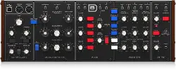
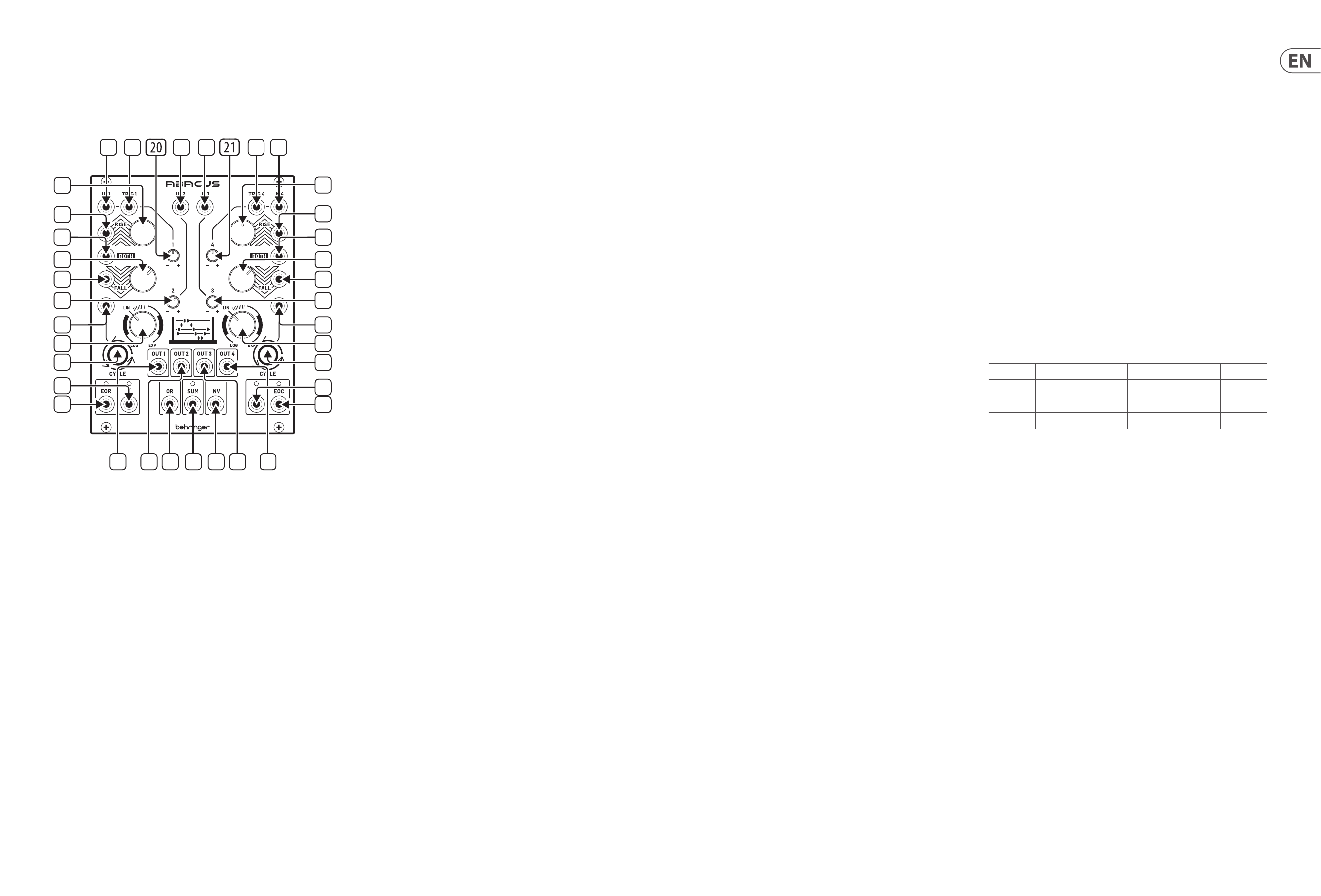
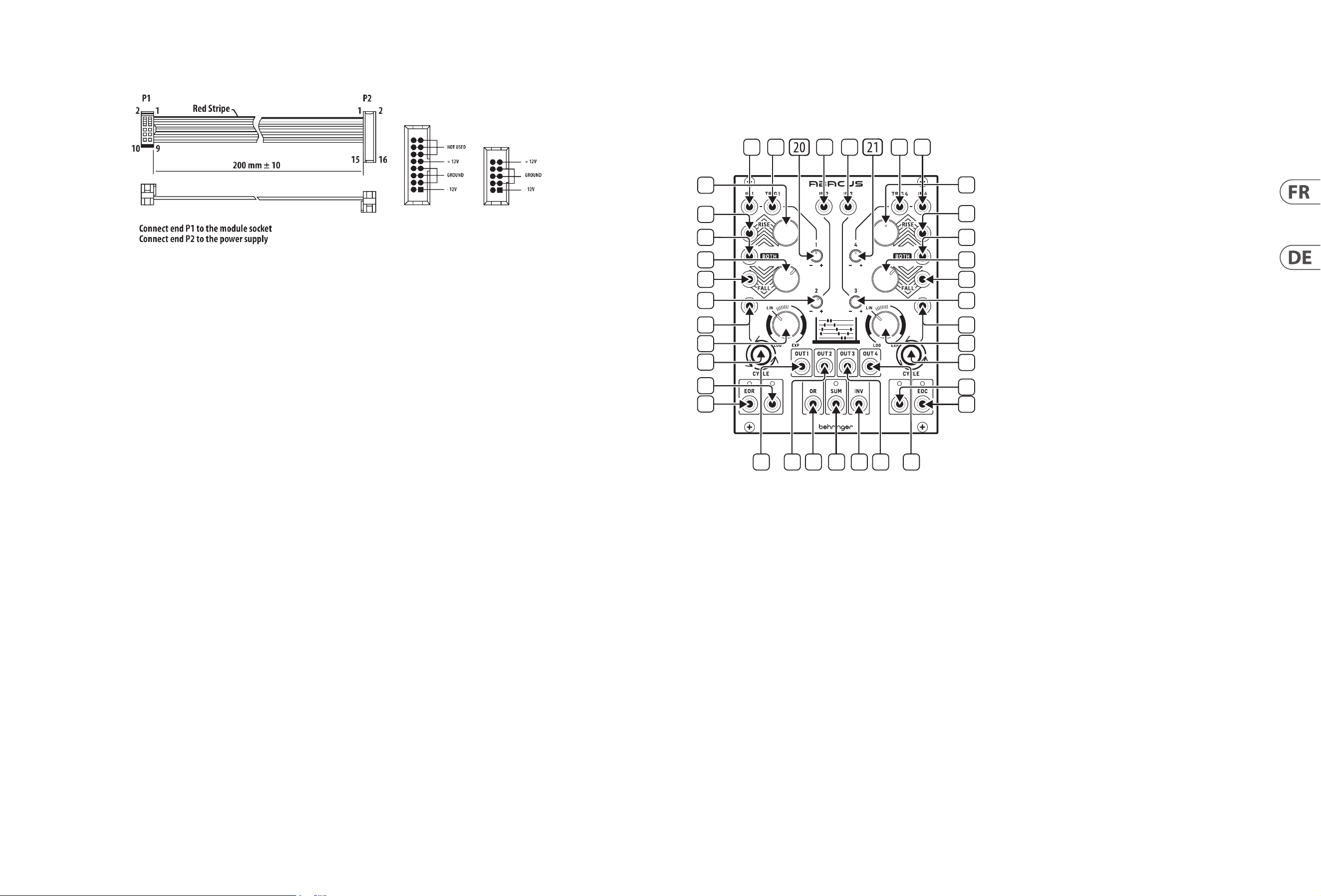
1. CHANNEL 1 CV INPUT – Accepts variable voltages in the range +/- 10 V
for processing by Channel 1. If no voltage is present the Abacus will use a
self-generated voltage of approximately +10 V.
2. CHANNEL 1 TRIGGER INPUT – Accepts any positive-going gate or trigger
above + 2.5 V. Causes the Rise/Fall function to be activated.
3. CHANNEL 2 CV INPUT – Accepts voltages in the range +/- 10 V for
attenuverting by control 20.
4. CHANNEL 3 CV INPUT – Accepts voltages in the range +/- 10 V for
attenuverting by control 21.
5. CHANNEL 4 TRIGGER INPUT – Accepts any positive-going gate or trigger
above + 2.5 V. Causes the Rise/Fall function to be activated.
6. CHANNEL 4 CV INPUT – Accepts variable voltages in the range +/- 10 V
for processing by Channel 4. If no voltage is present the Abacus will use a
self-generated voltage of approximately +10 V.
7. CHANNEL 1 RISE CV INPUT – Allows CV control of the Rise function,
in conjunction with control 8. Accepts voltages in the range +/- 8 V.
Positive voltages increase the Rise time until the maximum is achieved;
negative voltages decrease it until it reaches minimum.
8. CHANNEL 1 RISE TIME – Use this control to set the Rise time. See table
below for maximum times according to dierent settings. Can be
modulated further by feeding a CV to socket 7.
9. CHANNEL 4 RISE TIME – Use this control to set the Rise time. See
table below for maximum times according to dierent settings. Can be
modulated further by feeding a CV to socket 10.
10. CHANNEL 4 RISE CV INPUT – Allows CV control of the Rise function, in
conjunction with control 9. Accepts voltages in the range +/- 8 V. Positive
voltages increase the Rise time until the maximum is achieved; negative
voltages decrease it until it reaches minimum.
11. CHANNEL 1 BOTH CV INPUT – Accepts a voltage in the range +/- 8 V.
A positive voltage will exponentially decrease the total Rise/Fall time, until
the minimum is reached; a negative voltage exponentially increases it until
it reaches maximum.
12. CHANNEL 2 ATTENUVERTER – Use this control to attenuate (CW) or
invert (CCW) voltages fed to Channel 2 input on socket 3 or the internally
generated voltage in the range -10 V to + 10 V.
13. CHANNEL 3 ATTENUVERTER – Use this control to attenuate (CW) or
invert (CCW) voltages fed to Channel 3 input on socket 4 or the internally
generated voltage in the range -5 V to + 6 V.
14. CHANNEL 4 BOTH CV INPUT – Accepts a voltage in the range +/- 8 V.
A positive voltage will exponentially decrease the total Rise/Fall time, until
the minimum is reached; a negative voltage exponentially increases it until
it reaches maximum.
15. CHANNEL 1 FALL CV INPUT – Allows CV control of the Fall function, in
conjunction with control 16. Accepts voltages in the range +/- 8 V. Positive
voltages increase the Fall time until the maximum is achieved; negative
voltages decrease it until it reaches minimum.
16. CHANNEL 1 FALL TIME – Use this control to set the Fall time. See table
below for maximum times according to dierent settings. Can be
modulated further by feeding a CV to socket 15.
17. CHANNEL 4 FALL TIME – Use this control to set the Fall time. See table
below for maximum times according to dierent settings. Can be
modulated further by feeding a CV to socket 18.
18. CHANNEL 4 FALL CV INPUT – Allows CV control of the Fall function, in
conjunction with control 16. Accepts voltages in the range +/- 8 V. Positive
voltages increase the Fall time until the maximum is achieved; negative
voltages decrease it until it reaches minimum.
19. CHANNEL 1 CYCLE TRIGGER – Allows an external positive going gate or
trigger of +2.5 V or more to trigger Channel 1’s Cycle function.
20. CHANNEL 1 ATTENUVERTER – Use this control to attenuate (CW) or invert
(CCW) the output of Channel 1 after Rise/Fall processing. Does not pass
internal voltage unless processing is taking place.
21. CHANNEL 4 ATTENUVERTER – Use this control to attenuate (CW) or invert
(CCW) the output of Channel 1 after Rise/Fall processing. Does not pass
internal voltage unless processing is taking place.
22. CHANNEL 4 CYCLE TRIGGER – Allows an external positive going gate or
trigger of +2.5 V or more to trigger Channel 4’s Cycle function.
23. CHANNEL 1 RESPONSE – Use this control to vary the response of Channel 1
from logarithmic through linear to exponential. See table below.
24. CHANNEL 4 RESPONSE – Use this control to vary the response of Channel 4
from logarithmic through linear to exponential. See table below.
25. CHANNEL 1 CYCLE – Use this button to initiate cycling of Channel 1; Rise
and Fall will cycle until button is pressed again to stop the cycle. Button is
illuminated when cycling. Button ashes when Cycle is externally triggered
via socket 19. Internal Cycle takes priority over external trigger.
26. CHANNEL 1 OUTPUT – Outputs the processed voltage from Channel 1.
27. CHANNEL 2 OUTPUT – Outputs the processed voltage from Channel 2.
28. CHANNEL 3 OUTPUT – Outputs the processed voltage from Channel 3.
29. CHANNEL 4 OUTPUT – Outputs the processed voltage from Channel 4.
30. CHANNEL 4 CYCLE – Use this button to initiate cycling of Channel 4; Rise
and Fall will cycle until button is pressed again to stop the cycle. Button is
illuminated when cycling. Button ashes when Cycle is externally triggered
via socket 22. Internal cycle takes priority over external trigger.
31. CHANNEL 1 END OF RISE OUTPUT – Outputs a + 9 V voltage at the top of
the Rise function, indicated by the associated LED, which continues active
until the end of the Fall cycle.
32. CHANNEL 1 UNITY OUTPUT – Outputs a 0 - +10 V voltage following
the Rise/Fall functions when Channel 1 is cycling; otherwise follows the
channel input unaected by the attenuverter. LED shows green for a
positive voltage, red for a negative one.
33. OR OUTPUT – Outputs the result of an analog OR function based on the
setting of the attenuverters for Channels 1 – 4 (controls 12, 13, 20, 21).
Channels 1 and 4 need an external voltage to be included.
34. SUM OUTPUT – Outputs a summed voltage in the range +/- 10 V based on
the settings of the attenuverters for Channels 1 – 4 (controls 12, 13, 20, 21).
LED shows green for a positive voltage, red for a negative one. Channels 1
and 4 need an external voltage to be included.
35. INVERTED SUM OUTPUT – Outputs the inversion of the Sum output 34.
36. CHANNEL 4 UNITY OUTPUT – Outputs a 0 - +10 V voltage following
the Rise/Fall functions when Channel 4 is cycling; otherwise follows the
channel input unaected by the attenuverter. LED shows green for a
positive voltage, red for a negative one.
37. CHANNEL 4 END OF CYCLE OUTPUT – Outputs a + 9 V voltage at the end
of the Rise/Fall cycle, indicated by the associated LED.
Maximum Function Times – Channel 1 & Channel 4
Control(s) and Attenuverter set to maximum (fully CW)
Rise Time Rise Peak Fall Time Fall Min Cycle Time
Log 9 m 0 s 9.48 v 25 m 15 s 0.03 v 42 m 45 s
Lin 55 s 9.48 v 50 s 0.03 v 1 m 45 s
Exp 7 s 4.5 v 5 s 0.03 v 10 s
Hints and Tips
• Channels 1 and 4 can be used to modulate each other’s Rise, Fall or
Both functions.
• Channel 4’s EOC trigger can be used to trigger an external Sample & Hold
generator which could then be used as a modulation source.
• Channel 1’s EOR output can be used as a modier to any CV input on channels
1 and 4; or as an external voltage input to any channel.
• Channels 2 and 3 can be used to provide an oset voltage for the CV inputs of
Channel 1 and 4.
• Experiment with the inverted sum voltage as a control source.
ABACUS Controls
1
2
3
4
5 6
8
9
10
11
7
12
19
23
25
32
26 27 33 34 35 28 29
37
36
30
24
22
31
16
15
13
14
17
18
(EN)
Controls
8 ABACUS Quick Start Guide 9
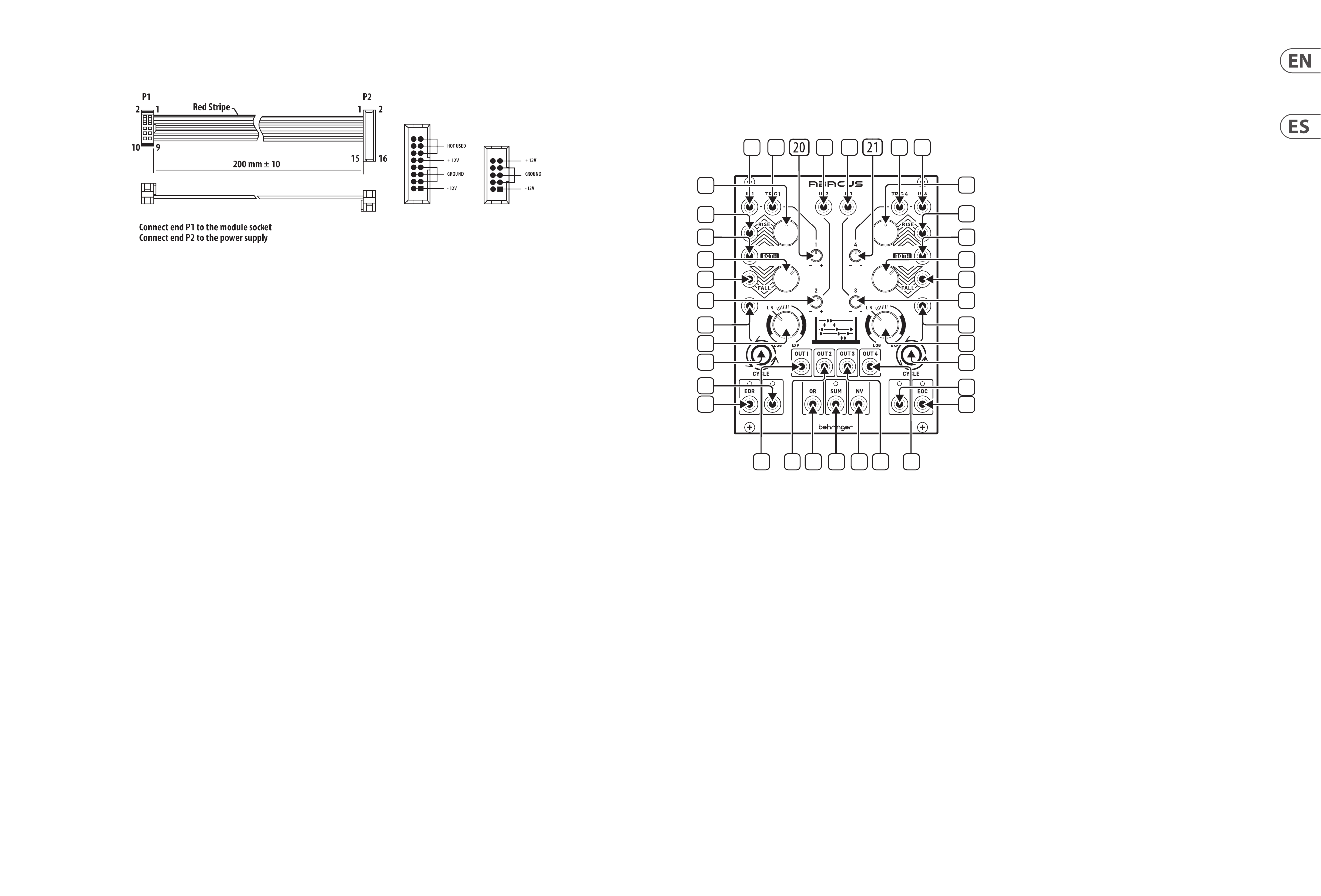
The module comes with the required power cable for connecting to a standard
Eurorack power supply system. Follow these steps to connect power to the
module. It is easier to make these connections before the module has been
mounted into a rack case.
1. Turn the power supply or rack case power o and disconnect the power cable.
2. Insert the 16-pin connector on the power cable into the socket on the power
supply or rack case. The connector has a tab that will align with the gap in
the socket, so it cannot be inserted incorrectly. If the power supply does not
have a keyed socket, be sure to orient pin 1 (-12 V) with the red stripe on
the cable.
3. Insert the 10-pin connector into the socket on the back of the module. The
connector has a tab that will align with the socket for correct orientation.
4. After both ends of the power cable have been securely attached, you may
mount the module in a case and turn on the power supply.
Installation
The necessary screws are included with the module for mounting in a Eurorack
case. Connect the power cable before mounting.
Depending on the rack case, there may be a series of xed holes spaced 2 HP
apart along the length of the case, or a track that allows individual threaded
plates to slide along the length of the case. The free-moving threaded plates
allow precise positioning of the module, but each plate should be positioned in
the approximate relation to the mounting holes in your module before attaching
the screws.
Hold the module against the Eurorack rails so that each of the mounting holes
are aligned with a threaded rail or threaded plate. Attach the screws part way
to start, which will allow small adjustments to the positioning while you get
them all aligned. After the nal position has been established, tighten the
screws down.
Power Connection
ABACUS Controles
(ES)
Controles
1. CHANNEL 1 CV INPUT – Acepta voltajes variables en el rango de
+/- 10 V para su procesado por el canal 1. Si no hay ningún voltaje presente,
el Abacus usará un voltaje auto-generado de aproximadamente +10 V.
2. CHANNEL 1 TRIGGER INPUT – Acepta cualquier señal de puerta o
disparador entrante positiva que supere los + 2.5 V. Esta señal hace que
la función Rise/Fall sea activada.
3. CHANNEL 2 CV INPUT – Acepta voltajes en el rango de +/- 10 V para
atenuarlos/invertirlos (“attenuverting”) por el control 20.
4. CHANNEL 3 CV INPUT – Acepta voltajes en el rango de +/- 10 V para
atenuarlos/invertirlos (“attenuverting”) por el control 21.
5. CHANNEL 4 TRIGGER INPUT – Acepta cualquier señal de puerta o
disparador entrante positiva que supere los + 2.5 V. Esta señal hace que
la función Rise/Fall sea activada.
6. CHANNEL 4 CV INPUT – Acepta voltajes variables en el rango de
+/- 10 V para su procesado por el canal 4. Si no hay ningún voltaje presente,
el Abacus usará un voltaje auto-generado de aproximadamente +10 V.
7. CHANNEL 1 RISE CV INPUT – Permite el control CV de la función Rise
junto con el control 8. Acepta voltajes en el rango de +/- 8 V. Los voltajes
positivos aumentan el tiempo del Rise (incremento) hasta que es alcanzado
el máximo; los voltajes negativos lo reducen hasta que es alcanzado
el mínimo.
8. CHANNEL 1 RISE TIME – Use este control para ajustar el tiempo del
incremento o Rise. Vea en la tabla de abajo los tiempos máximos obtenidos
de acuerdo con los diferentes ajustes. Puede modular esto aún más dando
entrada a una señal CV en la toma 7.
9. CHANNEL 4 RISE TIME – Use este control para ajustar el tiempo del
incremento o Rise. Vea en la tabla de abajo los tiempos máximos obtenidos
de acuerdo con los diferentes ajustes. Puede modular esto aún más dando
entrada a una señal CV en la toma 10.
10. CHANNEL 4 RISE CV INPUT – Permite el control CV de la función Rise
junto con el control 9. Acepta voltajes en el rango de +/- 8 V. Los voltajes
positivos aumentan el tiempo del Rise (incremento) hasta que es alcanzado
el máximo; los voltajes negativos lo reducen hasta que es alcanzado
el mínimo.
11. CHANNEL 1 BOTH CV INPUT – Acepta un voltaje en el rango de
+/- 8 V. Un voltaje positivo reducirá de forma exponencial el tiempo
Rise/Fall total, hasta que llegue al mínimo; un voltaje negativo aumentará
exponencialmente ese tiempo hasta llegar al máximo.
12. CHANNEL 2 ATTENUVERTER – Use este control para atenuar (derecha)
o invertir (izquierda) los voltajes enviados a la entrada del canal 2 en la
toma 3 o el voltaje generado internamente en el rango de -10 a + 10 V.
13. CHANNEL 3 ATTENUVERTER – Use este control para atenuar (derecha)
o invertir (izquierda) los voltajes enviados a la entrada del canal 3 en la
toma 4 o el voltaje generado internamente en el rango de -5 a + 6 V.
14. CHANNEL 4 BOTH CV INPUT – Acepta un voltaje en el rango de
+/- 8 V. Un voltaje positivo reducirá de forma exponencial el tiempo
Rise/Fall total, hasta que llegue al mínimo; un voltaje negativo aumentará
exponencialmente ese tiempo hasta llegar al máximo.
1
2
3
4
5 6
8
9
10
11
7
12
19
23
25
32
26 27 33 34 35 28 29
37
36
30
24
22
31
16
15
13
14
17
18
10 ABACUS Quick Start Guide 11
15. CHANNEL 1 FALL CV INPUT – Permite el control CV de la función Fall
junto con el control 16. Acepta voltajes en el rango de +/- 8 V. Los voltajes
positivos aumentan el tiempo del Fall (decremento) hasta que es alcanzado
el máximo; los voltajes negativos lo reducen hasta que es alcanzado
el mínimo.
16. CHANNEL 1 FALL TIME – Use este control para ajustar el tiempo del
decremento o Fall. Vea en la tabla de abajo los tiempos máximos obtenidos
de acuerdo con los diferentes ajustes. Puede modular esto aún más dando
entrada a una señal CV en la toma 15.
17. CHANNEL 4 FALL TIME – Use este control para ajustar el tiempo del
decremento o Fall. Vea en la tabla de abajo los tiempos máximos obtenidos
de acuerdo con los diferentes ajustes. Puede modular esto aún más dando
entrada a una señal CV en la toma 18.
18. CHANNEL 4 FALL CV INPUT – Permite el control CV de la función Fall
junto con el control 17. Acepta voltajes en el rango de +/- 8 V. Los voltajes
positivos aumentan el tiempo del Fall (decremento) hasta que es alcanzado
el máximo; los voltajes negativos lo reducen hasta que es alcanzado
el mínimo.
19. CHANNEL 1 CYCLE TRIGGER – Permite que una señal de puerta o
disparador positiva entrante de +2.5 V o superior active la función Cycle
del canal 1.
20. CHANNEL 1 ATTENUVERTER – Use este control para atenuar (derecha)
o invertir (izquierda) la salida del canal 1 después del procesado Rise/Fall.
No pasa voltaje interno salvo que esté ejecutándose el procesado.
21. CHANNEL 4 ATTENUVERTER – Use este control para atenuar (derecha)
o invertir (izquierda) la salida del canal 4 después del procesado Rise/Fall.
No pasa voltaje interno salvo que esté ejecutándose el procesado.
22. CHANNEL 4 CYCLE TRIGGER – Permite que una señal de puerta o
disparador positiva entrante de +2.5 V o superior active la función Cycle
del canal 4.
23. CHANNEL 1 RESPONSE – Use este control para modicar la respuesta
del canal 1 desde logarítmica a exponencial pasando por lineal. Vea la
tabla de abajo.
24. CHANNEL 4 RESPONSE – Use este control para modicar la respuesta
del canal 4 desde logarítmica a exponencial pasando por lineal. Vea la
tabla de abajo.
25. CHANNEL 1 CYCLE – Use este botón para iniciar el bucle o ciclo del canal
1; las funciones Rise y Fall harán un bucle hasta que vuelva a pulsar este
botón para detener ese ciclo. El botón quedará iluminado cuando el bucle
esté activo. El botón parpadeará cuando el efecto de bucle sea disparado
externamente a través de la toma 19. El bucle interno tendrá prioridad
sobre el bucle externo.
26. CHANNEL 1 OUTPUT – Emite el voltaje procesado del canal 1.
27. CHANNEL 2 OUTPUT – Emite el voltaje procesado del canal 2.
28. CHANNEL 3 OUTPUT – Emite el voltaje procesado del canal 3.
29. CHANNEL 4 OUTPUT – Emite el voltaje procesado del canal 4.
30. CHANNEL 4 CYCLE – Use este botón para iniciar el bucle o ciclo del canal
4; las funciones Rise y Fall harán un bucle hasta que vuelva a pulsar este
botón para detener ese ciclo. El botón quedará iluminado cuando el bucle
esté activo. El botón parpadeará cuando el efecto de bucle sea disparado
externamente a través de la toma 22. El bucle interno tendrá prioridad
sobre el bucle externo.
31. CHANNEL 1 END OF RISE OUTPUT – Esta salida emite un voltaje de
+ 9 V en el extremo superior de la función Rise, indicado por el piloto
LED asociado, que continuará activo hasta el nal del ciclo Fall.
32. CHANNEL 1 UNITY OUTPUT – Emite un voltaje 0 - +10 V siguiendo las
funciones Rise/Fall cuando hay activo un bucle en el canal 1; en caso
contrario sigue la señal de la entrada del canal sin afectación por el
atenuador/inversor. El piloto LED se ilumina en verde para un voltaje
positivo o en rojo para uno negativo.
33. OR OUTPUT – Esta toma da salida al resultado de una función OR analógica
basada en el ajuste de los atenuadores/inversores de los canales 1 – 4
(controles 12, 13, 20, 21). Los canales 1 y 4 necesitan un voltaje externo para
ser incluidos.
34. SUM OUTPUT – Esta salida emite un voltaje sumado en el rango
+/- 10 V basado en los ajustes de los atenuadores/inversores de los canales
1 – 4 (controles 12, 13, 20, 21). El piloto LED se ilumina en verde para un
voltaje positivo y en rojo para uno negativo. Los canales 1 y 4 necesitan un
voltaje externo para ser incluidos.
35. INVERTED SUM OUTPUT – Da salida a la inversión de la salida Sum 34.
36. CHANNEL 4 UNITY OUTPUT – Emite un voltaje 0 - +10 V siguiendo las
funciones Rise/Fall cuando hay activo un bucle en el canal 4; en caso
contrario sigue la señal de la entrada del canal sin afectación por el
atenuador/inversor. El piloto LED se ilumina en verde para un voltaje
positivo o en rojo para uno negativo.
37. CHANNEL 4 END OF CYCLE OUTPUT – Esta salida emite un voltaje de
+ 9 V al nal del ciclo o bucle de la función Rise/Fall, indicado por el piloto
LED asociado.
Tiempos máximos de función – Canal 1 y Canal 4
Control(es) y atenuadores/inversores ajustados al máximo (tope derecho)
Tiempo
Rise
Pico
Rise
Tiempo
Fall
Mínimo
Fall
Tiempo
Cycle
Log 9 m 0 s 9.48 v 25 m 15 s 0.03 v 42 m 45 s
Lin 55 s 9.48 v 50 s 0.03 v 1 m 45 s
Exp 7 s 4.5 v 5 s 0.03 v 10 s
Notas y avisos
• Puede usar los canales 1 y 4 para modular las funciones Rise, Fall o Both del
otro canal.
• Puede usar el disparador EOC del canal 4 para conmutar un generador
S&H (muestreo y mantenimiento) que puede usar después como una fuente
de modulación.
• Puede usar la salida EOR del canal 1 como un modicador para cualquier
entrada CV de los canales 1 y 4, o como una entrada de voltaje externo para
cualquier canal.
• Puede usar los canales 2 y 3 para ofrecer un voltaje de desfase u oset para las
entradas CV del canal 1 y 4.
• Experimente con el voltaje de suma invertido como una fuente de control.
El módulo viene con el cable de alimentación necesario para conectarse a un
sistema de suministro de energía Eurorack estándar. Siga estos pasos para
conectar la alimentación al módulo. Es más fácil realizar estas conexiones antes
de que el módulo se haya montado en una caja de rack.
1. Apague la fuente de alimentación o la caja del bastidor y desconecte el cable
de alimentación.
2. Inserte el conector de 16 clavijas del cable de alimentación en la toma de
la fuente de alimentación o en la caja del bastidor. El conector tiene una
pestaña que se alineará con el espacio en el zócalo, por lo que no se puede
insertar incorrectamente. Si la fuente de alimentación no tiene un enchufe
con llave, asegúrese de orientar el pin 1 (-12 V) con la raya roja en el cable.
3. Inserte el conector de 10 pines en el zócalo en la parte posterior del módulo.
El conector tiene una pestaña que se alineará con el enchufe para una
orientación correcta.
4. Una vez que ambos extremos del cable de alimentación se hayan conectado
de forma segura, puede montar el módulo en una caja y encender la fuente
de alimentación.
Instalación
Los tornillos necesarios se incluyen con el módulo para su montaje en una caja
Eurorack. Conecte el cable de alimentación antes del montaje.
Dependiendo de la caja del bastidor, puede haber una serie de oricios jos
separados 2 HP a lo largo de la caja, o una pista que permita que las placas
roscadas individuales se deslicen a lo largo de la caja. Las placas roscadas de
movimiento libre permiten un posicionamiento preciso del módulo, pero cada
placa debe colocarse en una relación aproximada con los oricios de montaje en
su módulo antes de colocar los tornillos.
Sostenga el módulo contra los rieles Eurorack de modo que cada uno de los
oricios de montaje esté alineado con un riel o placa roscada. Coloque los
tornillos parcialmente para comenzar, lo que permitirá pequeños ajustes en la
posición mientras los alinea todos. Una vez establecida la posición nal, apriete
los tornillos.
Conexión Eléctrica
ABACUS Controles
12 ABACUS Quick Start Guide 13
ABACUS Réglages
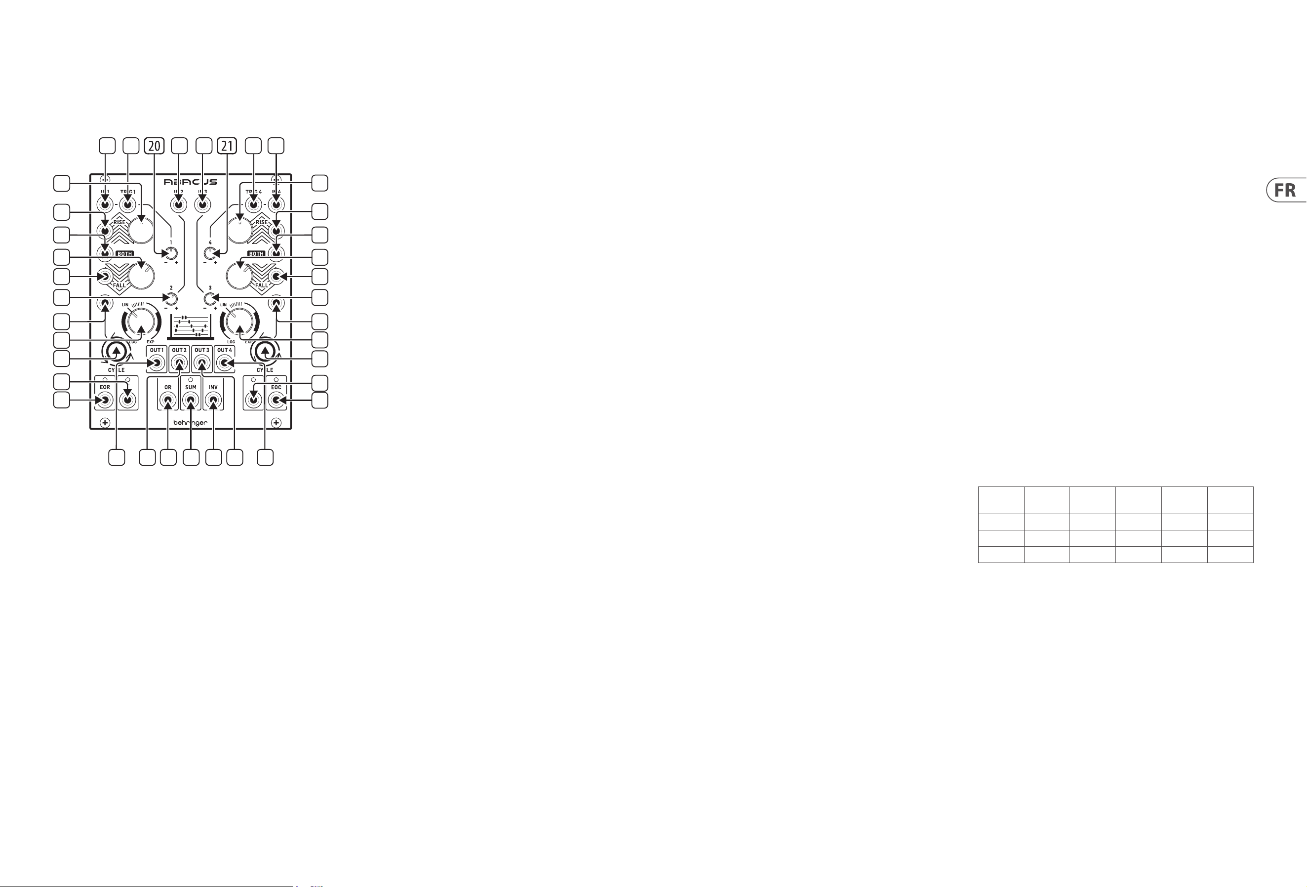
(FR)
Réglages
1. CHANNEL 1 CV INPUT – Peut recevoir des tensions sur une plage de
+/- 10 V pour traitement par le canal 1. Si aucune tension n’est détectée,
l’Abacus utilise une tension auto-générée d’approximativement +10 V.
2. CHANNEL 1 TRIGGER INPUT – Peut recevoir des signaux de gate ou de
déclenchement supérieurs à + 2.5 V. Permet d’activer la fonction Rise/Fall.
3. CHANNEL 2 CV INPUT – Peut recevoir des tensions sur une plage de
+/- 10 V pour atténuation/inversion (attenuverting) par le réglage 20.
4. CHANNEL 3 CV INPUT – Peut recevoir des tensions sur une plage de
+/- 10 V pour atténuation/inversion (attenuverting) par le réglage 21.
5. CHANNEL 4 TRIGGER INPUT – Peut recevoir des signaux de gate ou de
déclenchement supérieurs à + 2.5 V. Permet d’activer la fonction Rise/Fall.
6. CHANNEL 4 CV INPUT – Peut recevoir des tensions sur une plage de
+/- 10 V pour traitement par le canal 4. Si aucune tension n’est détectée,
l’Abacus utilise une tension auto-générée d’approximativement +10 V.
7. CHANNEL 1 RISE CV INPUT – Permet de contrôler la fonction Rise par
CV, en conjonction avec le réglage 8. Peut recevoir des tensions sur une
plage de +/- 8 V. Une tension positive augmente la durée de la fonction
Rise jusqu’à ce que la valeur maximale soit atteinte ; une tension négative
diminue sa durée jusqu’à ce que la valeur minimale soit atteinte.
8. CHANNEL 1 RISE TIME – Permet de régler la durée de la fonction Rise.
Le tableau ci-dessous indique des durées maximales en fonction de
diérents réglages. La durée peut être modulée avec une CV reliée
à l’entrée 7.
9. CHANNEL 4 RISE TIME – Permet de régler la durée de la fonction Rise.
Le tableau ci-dessous indique des durées maximales en fonction de
diérents réglages. La durée peut être modulée avec une CV reliée
à l’entrée 10.
10. CHANNEL 4 RISE CV INPUT – Permet de contrôler la fonction Rise par CV,
en conjonction avec le réglage 9. Peut recevoir des tensions sur une plage de
+/- 8 V. Une tension positive augmente la durée de la fonction Rise jusqu’à
ce que la valeur maximale soit atteinte ; une tension négative diminue sa
durée jusqu’à ce que la valeur minimale soit atteinte.
11. CHANNEL 1 BOTH CV INPUT – Peut recevoir des tensions sur une plage
de +/- 8 V. Une tension positive diminue de manière exponentielle la
durée totale des fonctions Rise et Fall jusqu’à ce que la valeur minimale
soit atteinte ; une tension négative augmente cette durée de manière
exponentielle jusqu’à ce que la valeur maximale soit atteinte.
12. CHANNEL 2 ATTENUVERTER – Ce réglage permet d’atténuer (vers la
droite) ou d’inverser (vers la gauche) les tensions transmises à l’entrée
3 du canal 2 ou la tension auto-générée sur une plage de -10 V à + 10 V.
13. CHANNEL 3 ATTENUVERTER – Ce réglage permet d’atténuer
(vers la droite) ou d’inverser (vers la gauche) les tensions transmises à
l’entrée 4 du canal 3 ou la tension auto-générée sur une plage de
-5 V à + 6 V.
14. CHANNEL 4 BOTH CV INPUT – Peut recevoir des tensions sur une plage
de +/- 8 V. Une tension positive diminue de manière exponentielle la
durée totale des fonctions Rise et Fall jusqu’à ce que la valeur minimale
soit atteinte ; une tension négative augmente cette durée de manière
exponentielle jusqu’à ce que la valeur maximale soit atteinte.
15. CHANNEL 1 FALL CV INPUT – Permet de contrôler la fonction Fall par
CV, en conjonction avec le réglage 16. Peut recevoir des tensions sur une
plage de +/- 8 V. Une tension positive augmente la durée de la fonction
Fall jusqu’à ce que la valeur maximale soit atteinte ; une tension négative
diminue sa durée jusqu’à ce que la valeur minimale soit atteinte.
16. CHANNEL 1 FALL TIME – Permet de régler la durée de la fonction Fall.
Le tableau ci-dessous indique des durées maximales en fonction de
diérents réglages. La durée peut être modulée avec une CV reliée
à l’entrée 15.
17. CHANNEL 4 FALL TIME – Permet de régler la durée de la fonction Fall.
Le tableau ci-dessous indique des durées maximales en fonction de
diérents réglages. La durée peut être modulée avec une CV reliée
à l’entrée 18.
18. CHANNEL 4 FALL CV INPUT – Permet de contrôler la fonction Fall par
CV, en conjonction avec le réglage 17. Peut recevoir des tensions sur une
plage de +/- 8 V. Une tension positive augmente la durée de la fonction
Fall jusqu’à ce que la valeur maximale soit atteinte ; une tension négative
diminue sa durée jusqu’à ce que la valeur minimale soit atteinte.
19. CHANNEL 1 CYCLE TRIGGER – Permet d’activer la fonction Cycle du canal
1 avec des signaux de gate ou de déclenchement externes supérieurs ou
égaux à + 2.5 V.
20. CHANNEL 1 ATTENUVERTER – Ce réglage permet d’atténuer
(vers la droite) ou d’inverser (vers la gauche) la sortie du canal 1 après
le traitement par la fonction Rise/Fall. Ne laisse pas passer la tension
interne sauf si le traitement est en cours.
21. CHANNEL 4 ATTENUVERTER – Ce réglage permet d’atténuer
(vers la droite) ou d’inverser (vers la gauche) la sortie du canal 4 après
le traitement par la fonction Rise/Fall. Ne laisse pas passer la tension
interne sauf si le traitement est en cours.
22. CHANNEL 4 CYCLE TRIGGER – Permet d’activer la fonction Cycle du
canal 4 avec des signaux de gate ou de déclenchement externes supérieurs
ou égaux à + 2.5 V.
23. CHANNEL 1 RESPONSE – Ce réglage permet de faire varier la réponse
du canal 1 de logarithmique à exponentielle en passant par linéaire.
Voir le tableau ci-dessous.
24. CHANNEL 4 RESPONSE – Ce réglage permet de faire varier la réponse
du canal 1 de logarithmique à exponentielle en passant par linéaire.
Voir le tableau ci-dessous.
25. CHANNEL 1 CYCLE – Utilisez ce bouton pour initier un cycle sur le canal 1 ;
le cycle des fonctions Rise et Fall continue jusqu’à ce que vous appuyiez à
nouveau sur le bouton pour l’arrêter. Le bouton s’allume lorsque le cycle
est en cours et clignote si le cycle est déclenché avec un signal externe
(entrée 19). Le cycle interne est prioritaire sur le déclenchement externe.
26. CHANNEL 1 OUTPUT – Permet de transmettre la tension traitée du canal 1.
27. CHANNEL 2 OUTPUT – Permet de transmettre la tension traitée du canal 2.
28. CHANNEL 3 OUTPUT – Permet de transmettre la tension traitée du canal 3.
29. CHANNEL 4 OUTPUT – Permet de transmettre la tension traitée du canal 4.
30. CHANNEL 4 CYCLE – Utilisez ce bouton pour initier un cycle sur le canal 4
; le cycle des fonctions Rise et Fall continue jusqu’à ce que vous appuyiez à
nouveau sur le bouton pour l’arrêter. Le bouton s’allume lorsque le cycle
est en cours et clignote si le cycle est déclenché avec un signal externe
(entrée 22). Le cycle interne est prioritaire sur le déclenchement externe.
31. CHANNEL 1 END OF RISE OUTPUT – Permet de transmettre une tension
de + 9 V lorsque la fonction Rise atteint son maximum. La LED adjacente
s’allume alors. Cette tension reste active jusqu’à la n du cycle de la
fonction Fall.
32. CHANNEL 1 UNITY OUTPUT – Porte une tension de 0 à +10 V générée à la
n les fonctions Rise/Fall lors du cycle sur le canal 1 ; elle suit sinon le signal
d’entrée du canal, non traité par l’atténuateur/inverseur. La LED s’allume en
vert si la tension est positive et en rouge pour une tension négative.
33. OR OUTPUT – Porte le résultat d’une fonction OR analogique basée sur le
réglage de l’atténuateur/inverseur des canaux 1 à 4 (réglages 12, 13, 20, 21).
Une tension externe est nécessaire pour que les canaux 1 et 4 soient inclus.
34. SUM OUTPUT – Porte une tension additionnée sur une plage de +/- 10 V
basée sur le réglage de l’atténuateur/inverseur des canaux 1 à 4 (réglages
12, 13, 20, 21). La LED s’allume en vert si la tension est positive et en rouge
pour une tension négative. Une tension externe est nécessaire pour que les
canaux 1 et 4 soient inclus.
35. INVERTED SUM OUTPUT – Porte une version inversée de la sortie
Sum (34).
36. CHANNEL 4 UNITY OUTPUT – Porte une tension de 0 à +10 V générée
les fonctions Rise/Fall lors du cycle sur le canal 4 ; elle suit sinon le signal
d’entrée du canal, non traité par l’atténuateur/inverseur. La LED s’allume en
vert si la tension est positive et en rouge pour une tension négative.
37. CHANNEL 4 END OF CYCLE OUTPUT – Porte une tension de + 9 V générée
à la n du cycle Rise/Fall, indiqué par la LED correspondante.
Durée maximale des fonctions – Canal 1 et canal 4
Réglage(s) et atténuateur/inverseur au maximum (tournés complètement à droite)
Durée
de Rise
Rise
Max
Durée
de Fall
Fall
Min
Durée
du cycle
Log 9 m 0 s 9.48 v 25 m 15 s 0.03 v 42 m 45 s
Lin 55 s 9.48 v 50 s 0.03 v 1 m 45 s
Exp 7 s 4.5 v 5 s 0.03 v 10 s
Trucs et astuces
• Les canaux 1 et 4 peuvent être utilisés pour moduler leurs fonctions
Rise, Fall ou Both.
• Le déclencheur EOC du canal 4 peut être utilisé pour déclencher un générateur
externe de Sample & Hold pouvant ensuite être utilisé comme source
de modulation.
• La sortie EOR du canal 1 peut être utilisée pour moduler les entrées CV des
canaux 1 et 4 ou comme générateur externe de tension pour tous les canaux.
• Les canaux 2 et 3 peuvent fournir une tension d’oset pour les entrées CV
des canaux 1 et 4.
• Essayez d’utiliser la tension additionnée inverse comme une source
de contrôle.
1
2
3
4
5 6
8
9
10
11
7
12
19
23
25
32
26 27 33 34 35 28 29
37
36
30
24
22
31
16
15
13
14
17
18
14 ABACUS Quick Start Guide 15
Le module est livré avec le câble d’alimentation requis pour la connexion à un
système d’alimentation standard Eurorack. Suivez ces étapes pour connecter
l’alimentation au module. Il est plus facile d’eectuer ces connexions avant que le
module n’ait été monté dans un boîtier de rack.
1. Mettez le bloc d’alimentation ou le boîtier de rack hors tension et
débranchez le câble d’alimentation.
2. Insérez le connecteur à 16 broches du câble d’alimentation dans la prise du
bloc d’alimentation ou du boîtier du rack. Le connecteur a une languette qui
s’alignera avec l’espace dans la prise, de sorte qu’il ne peut pas être inséré de
manière incorrecte. Si le bloc d’alimentation n’a pas de prise à clé, veillez à
orienter la broche 1 (-12 V) avec la bande rouge sur le câble.
3. Insérez le connecteur à 10 broches dans la prise à l’arrière du module.
Le connecteur a une languette qui s’alignera avec la prise pour une
orientation correcte.
4. Une fois que les deux extrémités du câble d’alimentation ont été
solidement xées, vous pouvez monter le module dans un boîtier et allumer
l’alimentation.
Installation
Les vis nécessaires sont incluses avec le module pour le montage dans un boîtier
Eurorack. Connectez le câble d'alimentation avant le montage.
Selon le boîtier de rack, il peut y avoir une série de trous xes espacés de 2 HP
le long de la longueur du boîtier, ou une piste qui permet aux plaques letées
individuelles de coulisser le long de la longueur du boîtier. Les plaques letées
mobiles permettent un positionnement précis du module, mais chaque plaque
doit être positionnée approximativement par rapport aux trous de montage de
votre module avant de xer les vis.
Maintenez le module contre les rails Eurorack de manière à ce que chacun des
trous de montage soit aligné avec un rail leté ou une plaque letée. Fixez les vis
partiellement pour commencer, ce qui permettra des ajustements mineurs de
positionnement pendant que vous les alignez tous. Après que la position nale a
été établie, serrez les vis.
Connexion Électrique
ABACUS Bedienelemente
(DE)
Bedienelemente
1. CHANNEL 1 CV INPUT – Akzeptiert variable Spannungen im Bereich von
+/-10 V zur Verarbeitung durch Kanal 1. Wenn keine Spannung anliegt ist,
verwendet der Abacus eine selbst erzeugte Spannung von etwa +10 V.
2. CHANNEL 1 TRIGGER INPUT – Akzeptiert jedes positive Gate- oder
Trigger-Signal über +2.5 V. Bewirkt, dass die Rise/Fall-Funktion
aktiviert wird.
3. CHANNEL 2 CV INPUT – Akzeptiert Spannungen im Bereich von
+/-10 V zum Abschwächen/Invertieren (Attenuverting) mit Regler 20.
4. CHANNEL 3 CV INPUT – Akzeptiert Spannungen im Bereich von
+/-10 V zum Abschwächen/Invertieren (Attenuverting) mit Regler 21.
5. CHANNEL 4 TRIGGER INPUT – Akzeptiert jedes positive Gate- oder
Trigger-Signal über +2.5 V. Bewirkt, dass die Rise/Fall-Funktion
aktiviert wird.
6. CHANNEL 4 CV INPUT – Akzeptiert variable Spannungen im Bereich von
+/-10 V zur Verarbeitung durch Kanal 4. Wenn keine Spannung anliegt ist,
verwendet der Abacus eine selbst erzeugte Spannung von etwa +10 V.
7. CHANNEL 1 RISE CV INPUT – Ermöglicht die CV-Steuerung der
Rise-Funktion in Verbindung mit Regler 8. Akzeptiert Spannungen im
Bereich von +/-8 V. Positive Spannungen erhöhen die Anstiegszeit bis zum
Erreichen des Maximums, negative Spannungen verringern sie bis zum
Erreichen des Minimums.
8. CHANNEL 1 RISE TIME – Mit diesem Regler können Sie die Anstiegszeit
einstellen. Siehe Tabelle unten für maximale Zeiten bei verschiedenen
Einstellungen. Kann durch Einspeisung einer CV in Buchse 7 weiter
moduliert werden.
9. CHANNEL 4 RISE TIME – Mit diesem Regler können Sie die Anstiegszeit
einstellen. Siehe Tabelle unten für maximale Zeiten bei verschiedenen
Einstellungen. Kann durch Einspeisung einer CV in Buchse 10 weiter
moduliert werden.
10. CHANNEL 4 RISE CV INPUT – Ermöglicht die CV-Steuerung der
Rise-Funktion in Verbindung mit Regler 9. Akzeptiert Spannungen im
Bereichvon +/-8 V. Positive Spannungen erhöhen die Anstiegszeit bis zum
Erreichen des Maximums, negative Spannungen verringern sie bis zum
Erreichen des Minimums.
11. CHANNEL 1 BOTH CV INPUT – Akzeptiert eine Spannung im Bereich
von +/-8 V. Eine positive Spannung verringert exponentiell die gesamte
Rise/Fall-Zeit, bis das Minimum erreicht ist. Eine negative Spannung erhöht
sie exponentiell, bis das Maximum erreicht ist.
12. CHANNEL 2 ATTENUVERTER – Mit diesem Regler können Sie die über
Buchse 3 in Kanal 2 eingespeisten Spannungen oder die intern erzeugte
Spannung im Bereich von -10 V bis +10 V abschwächen (Rechtsdrehung)
oder invertieren (Linksdrehung).
13. CHANNEL 3 ATTENUVERTER – Mit diesem Regler können Sie die über
Buchse 4 in Kanal 3 eingespeisten Spannungen oder die intern erzeugte
Spannung im Bereich von -5 V bis +6 V abschwächen (Rechtsdrehung)
oder invertieren (Linksdrehung).
14. CHANNEL 4 BOTH CV INPUT – Akzeptiert eine Spannung im Bereich
von +/-8 V. Eine positive Spannung verringert exponentiell die gesamte
Rise/Fall-Zeit, bis das Minimum erreicht ist. Eine negative Spannung
erhöht sie exponentiell, bis das Maximum erreicht ist.
1
2
3
4
5 6
8
9
10
11
7
12
19
23
25
32
26 27 33 34 35 28 29
37
36
30
24
22
31
16
15
13
14
17
18
16 ABACUS Quick Start Guide 17
15. CHANNEL 1 FALL CV INPUT – Ermöglicht die CV-Steuerung der
Fall-Funktion in Verbindung mit Regler 16. Akzeptiert Spannungen im
Bereich von +/-8 V. Positive Spannungen erhöhen die Abfallzeit bis zum
Erreichen des Maximums, negative Spannungen verringern sie bis zum
Erreichen des Minimums.
16. CHANNEL 1 FALL TIME– Mit diesem Regler können Sie die Abfallzeit
einstellen. Siehe Tabelle unten für maximale Zeiten bei verschiedenen
Einstellungen. Kann durch Einspeisung einer CV in Buchse 15 weiter
moduliert werden.
17. CHANNEL 4 FALL TIME – Mit diesem Regler können Sie die Abfallzeit
einstellen. Siehe Tabelle unten für maximale Zeiten bei verschiedenen
Einstellungen. Kann durch Einspeisung einer CV in Buchse 18 weiter
moduliert werden.
18. CHANNEL 4 FALL CV INPUT – Ermöglicht die CV-Steuerung der
Fall-Funktion in Verbindung mit Regler 17. Akzeptiert Spannungen im
Bereich von +/-8 V. Positive Spannungen erhöhen die Abfallzeit bis zum
Erreichen des Maximums, negative Spannungen verringern sie bis zum
Erreichen des Minimums.
19. CHANNEL 1 CYCLE TRIGGER – ermöglicht einem externen positiven
Gate- oder Trigger-Signal von +2.5 V oder mehr, die Cycle-Funktion von
Kanal 1 zu triggern.
20. CHANNEL 1 ATTENUVERTER – Mit diesem Regler kann man den Ausgang
von Kanal 1 nach der Rise/Fall-Verarbeitung abschwächen (Rechtsdrehung)
oder invertieren (Linksdrehung). Es wird keine interne Spannung
weitergeleitet, wenn keine Verarbeitung stattndet.
21. CHANNEL 4 ATTENUVERTER – Mit diesem Regler kann man den Ausgang
von Kanal 4 nach der Rise/Fall-Verarbeitung abschwächen (Rechtsdrehung)
oder invertieren (Linksdrehung). Es wird keine interne Spannung
weitergeleitet, wenn keine Verarbeitung stattndet.
22. CHANNEL 4 CYCLE TRIGGER – ermöglicht einem externen positiven
Gate- oder Trigger-Signal von +2.5 V oder mehr, die Cycle-Funktion von
Kanal 4 zu triggern.
23. CHANNEL 1 RESPONSE – Mit diesem Regler können Sie die Ansprache
von Kanal 1 von logarithmisch über linear bis exponentiell variieren.
Siehe Tabelle unten.
24. CHANNEL 4 RESPONSE – Mit diesem Regler können Sie die Ansprache
von Kanal 4 von logarithmisch über linear bis exponentiell variieren.
Siehe Tabelle unten.
25. CHANNEL 1 CYCLEE – Mit dieser Taste kann man das Cycling von
Kanal 1 starten. Rise und Fall werden so lange zyklisch wiederholt,
bis die Taste erneut gedrückt wird, um den Zyklus zu stoppen. Die Taste
leuchtet während des Zyklus. Die Taste blinkt, wenn der Zyklus über
Buchse 19 extern getriggert wird. Das interne Cycling hat Vorrang vor dem
externen Trigger.
26. CHANNEL 1 OUTPUT – Gibt die verarbeitete Spannung von Kanal 1 aus.
27. CHANNEL 2 OUTPUT – Gibt die verarbeitete Spannung von Kanal 2 aus.
28. CHANNEL 3 OUTPUT – Gibt die verarbeitete Spannung von Kanal 3 aus.
29. CHANNEL 4 OUTPUT – Gibt die verarbeitete Spannung von Kanal 4 aus.
30. CHANNEL 4 CYCLE – Mit dieser Taste kann man das Cycling von Kanal 4
starten. Rise und Fall werden so lange zyklisch wiederholt, bis die Taste
erneut gedrückt wird, um den Zyklus zu stoppen. Die Taste leuchtet
während des Zyklus. Die Taste blinkt, wenn der Zyklus über Buchse 22
extern getriggert wird. Das interne Cycling hat Vorrang vor dem
externen Trigger.
31. CHANNEL 1 END OF RISE OUTPUT – Gibt an der Spitze der
Rise-Funktion eine Spannung von +9 V aus. Dies wird durch die zugehörige
LED angezeigt, die bis zum Ende des Fall-Zyklus aktiv bleibt.
32. CHANNEL 1 UNITY OUTPUT – Gibt eine Spannung von 0 bis +10 V aus,
die den Rise/Fall-Funktionen folgt, wenn Kanal 1 im Cycling- Modus ist.
Andernfalls folgt der Ausgang dem Kanaleingang unbeeinusst vom
Attenuverter. Die LED leuchtet grün bei positiver Spannung und rot bei
negativer Spannung.
33. OR OUTPUT – Gibt das Ergebnis einer analogen OR-Funktion aus, basierend
auf der Einstellung der Attenuverter für die Kanäle 1 - 4 (Regler 12, 13,
20, 21). Die Kanäle 1 und 4 benötigen eine externe Spannung, um
einbezogen zu werden.
34. SUM OUTPUT – Gibt eine Summenspannung im Bereich von
+/-10 V aus, basierend auf den Einstellungen der Attenuverter für die
Kanäle 1 - 4 (Regler 12, 13, 20, 21). Die LED leuchtet grün für eine positive
Spannung und rot für eine negative. Die Kanäle 1 und 4 benötigen eine
externe Spannung, um einbezogen zu werden.
35. INVERTED SUM OUTPUT – Gibt die Inversion des Summenausgangs 34 aus.
36. CHANNEL 4 UNITY OUTPUT – Gibt eine Spannung von 0 bis +10 V aus,
die den Rise/Fall-Funktionen folgt, wenn Kanal 4 im Cycling- Modus ist.
Andernfalls folgt der Ausgang dem Kanaleingang unbeeinusst vom
Attenuverter. Die LED leuchtet grün bei positiver Spannung und rot bei
negativer Spannung.
37. CHANNEL 4 END OF CYCLE OUTPUT – Gibt am Ende des Rise/Fall-Zyklus
eine Spannung von +9 V aus, was durch die zugehörige LED angezeigt wird.
Maximale Funktionszeiten – Kanal 1 & Kanal 4
Regler und Attenuverter auf Maximum eingestellt (komplette Rechtsdrehung)
Rise-Zeit Rise-Spitze Fall-Zeit Fall-Min. Cycle-Zeit
Log 9 m 0 s 9.48 v 25 m 15 s 0.03 v 42 m 45 s
Lin 55 s 9.48 v 50 s 0.03 v 1 m 45 s
Exp 7 s 4.5 v 5 s 0.03 v 10 s
Hinweise und Tipps
• Die Kanäle 1 und 4 können zur gegenseitigen Modulation der Funktionen Rise,
Fall oder Both verwendet werden.
• Der EOC-Trigger von Kanal 4 kann einen externen Sample & Hold-Generator
triggern, der dann als Modulationsquelle verwendet werden kann.
• Der EOR-Ausgang von Kanal 1 kann als Modier für jeden CV-Eingang
der Kanäle 1 und 4 oder als externer Spannungseingang für jeden Kanal
verwendet werden.
• Die Kanäle 2 und 3 können eine Oset-Spannung für die CV-Eingänge von
Kanal 1 und 4 bereitstellen.
• Experimentieren Sie mit der invertierten Summenspannung als Steuerquelle.
Das Modul wird mit dem erforderlichen Stromkabel für den Anschluss an ein
Standard-Eurorack-Stromversorgungssystem geliefert. Befolgen Sie diese Schritte,
um das Modul mit Strom zu versorgen. Es ist einfacher, diese Verbindungen
herzustellen, bevor das Modul in ein Rackgehäuse eingebaut wurde.
1. Schalten Sie das Netzteil oder das Rackgehäuse aus und ziehen Sie das
Netzkabel ab.
2. Stecken Sie den 16-poligen Stecker am Netzkabel in die Buchse am Netzteil
oder im Rack-Gehäuse. Der Anschluss verfügt über eine Lasche, die an
der Lücke in der Buchse ausgerichtet ist, sodass sie nicht falsch eingesetzt
werden kann. Wenn das Netzteil keine Schlüsselbuchse hat, achten Sie
darauf, Pin 1 (-12 V) mit dem roten Streifen am Kabel auszurichten.
3. Stecken Sie den 10-poligen Stecker in die Buchse auf der Rückseite
des Moduls. Der Anschluss verfügt über eine Lasche, die zur korrekten
Ausrichtung an der Buchse ausgerichtet wird.
4. Nachdem beide Enden des Netzkabels fest angeschlossen wurden, können
Sie das Modul in einem Gehäuse montieren und die Stromversorgung
einschalten.
Installation
Die erforderlichen Schrauben sind im Lieferumfang des Moduls für die Montage
in einem Eurorack-Gehäuse enthalten. Schließen Sie das Netzkabel vor der
Montage an.
Abhängig vom Rack-Gehäuse kann es eine Reihe von festen Löchern geben,
die entlang der Länge des Gehäuses 2 PS voneinander entfernt sind, oder eine
Schiene, mit der einzelne Gewindeplatten entlang der Länge des Gehäuses
gleiten können. Die frei beweglichen Gewindeplatten ermöglichen eine
präzise Positionierung des Moduls. Jede Platte sollte jedoch in der ungefähren
Beziehung zu den Befestigungslöchern in Ihrem Modul positioniert werden,
bevor Sie die Schrauben anbringen.
Halten Sie das Modul so gegen die Eurorack-Schienen, dass jedes der
Befestigungslöcher mit einer Gewindeschiene oder einer Gewindeplatte
ausgerichtet ist. Bringen Sie die Schrauben teilweise an, um zu beginnen.
Dadurch können Sie die Position geringfügig anpassen, während Sie alle
ausrichten. Ziehen Sie die Schrauben fest, nachdem die endgültige Position
festgelegt wurde.
Netzanschluss
ABACUS Bedienelemente

18 ABACUS Quick Start Guide 19
ABACUS Controles
(PT)
Controles
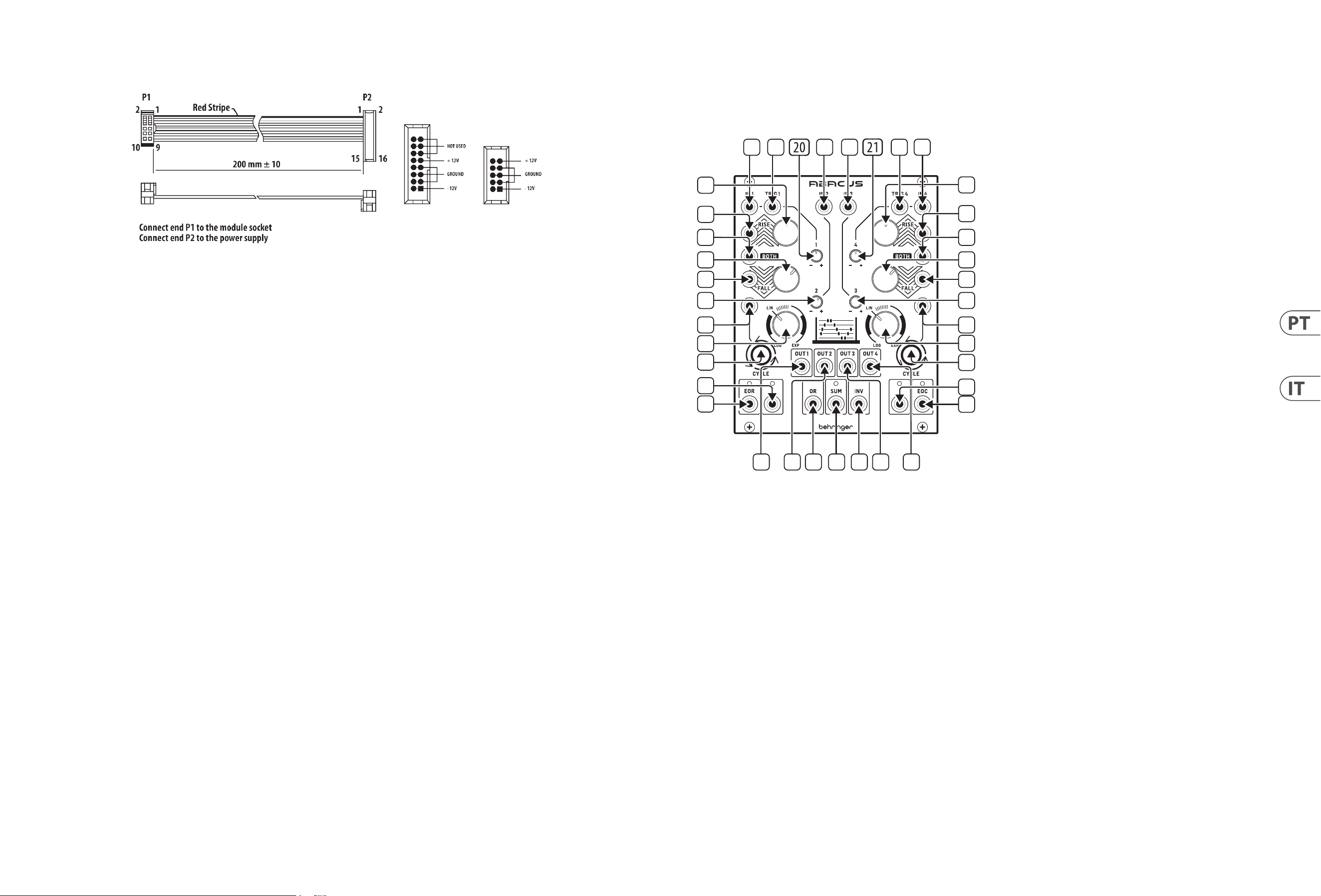
1. CHANNEL 1 CV INPUT – Aceita tensões variáveis na gama de +/- 10 V para
o processamento feito pelo Canal 1. Se não houver tensão presente,
o Abacus usará tensão autogerada de aproximadamente +10 V.
2. CHANNEL 1 TRIGGER INPUT – Aceita qualquer gate ou trigger de
andamento positivo acima de + 2.5 V. Ativa a função Rise/Fall.
3. CHANNEL 2 CV INPUT – Aceita tensões na gama de +/- 10 V para a
atenuação/inversão (attenuverting) do controle 20.
4. CHANNEL 3 CV INPUT – Aceita tensões na gama de +/- 10 V para a
atenuação/inversão (attenuverting) do controle 21.
5. CHANNEL 4 TRIGGER INPUT – Aceita qualquer gate ou trigger de
andamento positivo acima de + 2.5 V. Ativa a função Rise/Fall.
6. CHANNEL 4 CV INPUT – Aceita tensões variáveis na gama de +/- 10 V
para o processamento feito pelo Canal 4. Se não houver tensão presente,
o Abacus usará tensão autogerada de aproximadamente +10 V.
7. CHANNEL 1 RISE CV INPUT – Possibilita o controle CV da função Rise
em conjunção ao controle 8. Aceita tensões na gama de +/- 8 V. Tensões
positivas aumentam o tempo de Rise até que chegue ao máximo; tensões
negativas o diminuem até que cheque ao mínimo.
8. CHANNEL 1 RISE TIME – Use este controle para ajustar o tempo de Rise.
Verique a tabela abaixo para obter os tempos máximos de acordo com
congurações diferentes. Pode ser modulado mais ao se alimentar um
CV à tomada 7.
9. CHANNEL 4 RISE TIME – Use este controle para ajustar o tempo de Rise.
Verique a tabela abaixo para obter os tempos máximos de acordo com
congurações diferentes. Pode ser modulado mais ao se alimentar um
CV à tomada 10.
10. CHANNEL 4 RISE CV INPUT – Possibilita o controle CV da função Rise
em conjunção ao controle 9. Aceita tensões na gama de +/- 8 V. Tensões
positivas aumentam o tempo de Rise até que chegue ao máximo; tensões
negativas o diminuem até que cheque ao mínimo.
11. CHANNEL 1 BOTH CV INPUT – Aceita tensões na gama de +/- 8 V. Uma
tensão positiva diminui exponencialmente o tempo total de Rise/Fall até
que chegue ao mínimo; uma tensão negativa o aumenta exponencialmente
até que chegue ao máximo.
12. CHANNEL 2 ATTENUVERTER – Use este controle para atenuar
(sentido horário) ou inverter (sentido anti-horário) tensões alimentadas
à entrada do Canal 2 input na tomada 3 ou tensão gerada internamente
na gama de -10 V to + 10 V.
13. CHANNEL 3 ATTENUVERTER – Use este controle para atenuar (sentido
horário) ou inverter (sentido anti-horário) tensões alimentadas à entrada
do Canal 3 na tomada 4 ou tensão gerada internamente na gama de
-5 V to + 6 V.
14. CHANNEL 4 BOTH CV INPUT – Aceita tensões na gama de +/- 8 V.
Uma tensão positiva diminui exponencialmente o tempo total de
Rise/Fall até que chegue ao mínimo; uma tensão negativa o aumenta
exponencialmente até que chegue ao máximo.
15. CHANNEL 1 FALL CV INPUT – Possibilita o controle CV da função Fall
em conjunção ao controle 16. Aceita tensões na gama de +/- 8 V. Tensões
positivas aumentam o tempo de Fall até que chegue ao máximo; tensões
negativas o diminuem até que cheque ao mínimo.
16. CHANNEL 1 FALL TIME – Use este controle para ajustar o tempo de Fall.
Verique a tabela abaixo para obter os tempos máximos de acordo com
congurações diferentes. Pode ser modulado mais ao se alimentar um CV à
tomada 15.
17. CHANNEL 4 FALL TIME – Use este controle para ajustar o tempo de Fall.
Verique a tabela abaixo para obter os tempos máximos de acordo com
congurações diferentes. Pode ser modulado mais ao se alimentar um CV à
tomada 18.
18. CHANNEL 4 FALL CV INPUT – Possibilita o controle CV da função Fall,
em conjunção ao controle 17. Aceita tensões na gama de +/- 8 V. Tensões
positivas aumentam o tempo de Fall até que chegue ao máximo; tensões
negativas o diminuem até que cheque ao mínimo.
19. CHANNEL 1 CYCLE TRIGGER – Permite que um gate ou trigger externo de
andamento positivo com +2.5 V ou mais acione a função Cycle do Canal 1.
20. CHANNEL 1 ATTENUVERTER – Use este controle para atenuar (sentido
horário) ou inverter (sentido anti-horário) a saída do Canal 1 depois do
processamento de Rise/Fall. Não passa tensão interna a não ser que o
processamento esteja ocorrendo.
21. CHANNEL 4 ATTENUVERTER – Use este controle para atenuar (sentido
horário) ou inverter (sentido anti-horário) a saída do Canal 4 depois do
processamento de Rise/Fall. Não passa tensão interna a não ser que o
processamento esteja ocorrendo.
22. CHANNEL 4 CYCLE TRIGGER – Permite que um gate ou trigger externo de
andamento positivo, com +2.5 V ou mais, acione a função Cycle do Canal 4.
23. CHANNEL 1 RESPONSE – Use este controle para que a resposta do Canal 1
varie de logarítmico por linear até exponencial. Vericar a tabela abaixo.
24. CHANNEL 4 RESPONSE – Use este controle para que a resposta do Canal 4
varie de logarítmico por linear até exponencial. Vericar a tabela abaixo.
25. CHANNEL 1 CYCLE – Use este botão para iniciar o ciclo do Canal 1; Rise e
Fall iniciarão seu ciclo até que o botão seja pressionado novamente a m de
parar o ciclo. O botão acende durante o ciclo. O botão pisca quando o ciclo é
acionado externamente pela tomada 19. O ciclo interno (Internal Cycle) tem
mais prioridade do que o acionador externo.
26. CHANNEL 1 OUTPUT – Faz a saída da tensão processada do Canal 1.
27. CHANNEL 2 OUTPUT – Faz a saída da tensão processada do Canal 2.
28. CHANNEL 3 OUTPUT – Faz a saída da tensão processada do Canal 3.
29. CHANNEL 4 OUTPUT– Faz a saída da tensão processada do Canal 4.
30. CHANNEL 4 CYCLE– Use este botão para iniciar o ciclo do Canal 4; Rise e
Fall iniciarão seu ciclo até que o botão seja pressionado novamente a m de
parar o ciclo. O botão acende durante o ciclo. O botão pisca quando o ciclo é
acionado externamente pela tomada 22. O ciclo interno (Internal Cycle) tem
mais prioridade do que o acionador externo.
31. CHANNEL 1 END OF RISE OUTPUT – Faz saída da tensão de + 9 V no topo
da função Rise, indicado pelo LED associado que continua ativo até o m
do ciclo Fall.
32. CHANNEL 1 UNITY OUTPUT – Faz a saída de tensão 0 - +10 V seguindo as
funções Rise/Fall durante o ciclo (cycling) do Canal 1; caso contrário, segue
a entrada do canal não afetada pelo atenuador/inversor (attenuverter).
O LED ca verde quando há tensão positiva, e vermelho quando há
tensão negativa.
33. OR OUTPUT – Faz a saída do resultado de uma função analógica OR com
base na conguração dos atenuadores/inversores (attenuverters) dos
Canais 1 – 4 (controles 12, 13, 20, 21). Os canais 1 e 4 precisam de tensão
externa incluída.
34. SUM OUTPUT – Faz a saída da soma de tensões dentro da gama +/- 10 V
com base nas congurações dos atenuadores/inversores (attenuverters) dos
Canais 1 – 4 (controles 12, 13, 20, 21). O LED ca verde quando há tensão
positiva, e vermelho quando há tensão negativa. Os canais 1 e 4 precisam
de tensão externa incluída.
35. INVERTED SUM OUTPUT – Faz a saída da inversão da soma da saída 34.
36. CHANNEL 4 UNITY OUTPUT – Faz a saída de tensão 0 - +10 V, seguindo as
funções Rise/Fall durante o ciclo (cycling) do Canal 4; caso contrário, segue
a entrada do canal não afetada pelo atenuador/inversor (attenuverter).
O LED ca verde quando há tensão positiva, e vermelho quando há tensão
negativa.
37. CHANNEL 4 END OF CYCLE OUTPUT – Faz saída da tensão de + 9 V no m
do ciclo Rise/Fall, indicado pelo LED associado.
Tempos de Função Máxima – Canal 1 e Canal 4
Controle(s) e Attenuverter ajustados ao máximo (sentido horário máximo)
Tempo
de Rise
Pico
de Rise
Tempo
de Fall
Min de
Fall
Tempo
do Ciclo
Log 9 m 0 s 9.48 v 25 m 15 s 0.03 v 42 m 45 s
Lin 55 s 9.48 v 50 s 0.03 v 1 m 45 s
Exp 7 s 4.5 v 5 s 0.03 v 10 s
Dicas e Sugestões
• Os Canais 1 e 4 podem ser usados para modular as funções Rise e Fall (ou
ambas) umas das outras.
• O trigger EOC do Canal 4 pode ser usado para acionar um gerador de Sample &
Hold externo que pode então ser usado como fonte de modulação.
• A saída EOR do Canal 1 pode ser usada como uma modicadora de qualquer
entrada CV nos canais 1 e 4; ou como uma entrada de tensão externa em
qualquer canal.
• Os Canais 2 e 3 podem ser usados para fornecer tensão de oset para as
entradas CV dos Canais 1 e 4.
• Experimente usar a tensão de soma invertida como fonte de controle.
1
2
3
4
5 6
8
9
10
11
7
12
19
23
25
32
26 27 33 34 35 28 29
37
36
30
24
22
31
16
15
13
14
17
18
20 ABACUS Quick Start Guide 21
O módulo vem com o cabo de alimentação necessário para conectar a um sistema
de fonte de alimentação Eurorack padrão. Siga estas etapas para conectar a
alimentação ao módulo. É mais fácil fazer essas conexões antes que o módulo
seja montado em um gabinete de rack.
1. Desligue a fonte de alimentação ou o gabinete do rack e desconecte o cabo
de alimentação.
2. Insira o conector de 16 pinos do cabo de alimentação no soquete da fonte
de alimentação ou no gabinete do rack. O conector possui uma aba que
se alinhará com a lacuna no soquete, portanto, não pode ser inserido
incorretamente. Se a fonte de alimentação não tiver um soquete chaveado,
certique-se de orientar o pino 1 (-12 V) com a faixa vermelha no cabo.
3. Insira o conector de 10 pinos no soquete na parte traseira do módulo. O
conector possui uma guia que se alinha ao soquete para orientação correta.
4. Depois que ambas as extremidades do cabo de alimentação forem
conectadas com segurança, você pode montar o módulo em uma caixa e
ligar a fonte de alimentação.
Instalação
Os parafusos necessários estão incluídos com o módulo para montagem em uma
caixa Eurorack. Conecte o cabo de alimentação antes da montagem.
Dependendo da caixa do rack, pode haver uma série de orifícios xos espaçados
de 2 HP ao longo do comprimento da caixa, ou um trilho que permite que placas
roscadas individuais deslizem ao longo do comprimento da caixa. As placas
roscadas de movimento livre permitem o posicionamento preciso do módulo,
mas cada placa deve ser posicionada em relação aproximada aos orifícios de
montagem em seu módulo antes de prender os parafusos.
Segure o módulo contra os trilhos Eurorack de forma que cada um dos orifícios
de montagem quem alinhados com um trilho ou placa rosqueada. Prenda os
parafusos parcialmente para começar, o que permitirá pequenos ajustes no
posicionamento enquanto você os alinha. Depois de estabelecida a posição nal,
aperte os parafusos.
Conexão de Força
ABACUS Controlli
(IT)
Controlli
1. CHANNEL 1 CV INPUT – Accetta tensioni variabili nell’intervallo +/- 10 V
per l’elaborazione dal canale 1. Se non è presente alcuna tensione, l’Abacus
userà una tensione autogenerata di circa +10 V.
2. CHANNEL 1 TRIGGER INPUT – Accetta qualsiasi gate o trigger ad
andamento positivo superiore a + 2.5 V. Attiva la funzione RISE/FALL.
3. CHANNEL 2 CV INPUT – Accetta tensioni variabili nell’intervallo
+/- 10 V per l’elaborazione ATTENUVERTING (attenuazione-inversione)
dal controllo 20.
4. CHANNEL 3 CV INPUT – Accetta tensioni variabili nell’intervallo +/- 10 V
per l’elaborazione ATTENUVERTING dal controllo 21.
5. CHANNEL 4 TRIGGER INPUT – Accetta qualsiasi gate o trigger ad
andamento positivo superiore a + 2.5 V. Attiva la funzione RISE/FALL.
6. CHANNEL 4 CV INPUT – Accetta tensioni variabili nell’intervallo +/- 10 V
per l’elaborazione dal canale 4. Se non è presente alcuna tensione, l’Abacus
userà una tensione autogenerata di circa +10 V.
7. CHANNEL 1 RISE CV INPUT – Permette il controllo CV della funzione RISE,
in combinazione con il controllo 8. Accetta tensioni nell’intervallo +/- 8 V.
Le tensioni positive aumentano il tempo di RISE no al raggiungimento del
massimo; le tensioni negative lo diminuiscono no a raggiungere il minimo.
8. CHANNEL 1 RISE TIME – Usate questo controllo per impostare il tempo
RISE. Fate riferimento alla seguente tabella per i tempi massimi in base alle
diverse impostazioni. Può essere ulteriormente modulato inserendo un
CV nella presa 7.
9. CHANNEL 4 RISE TIME – Usate questo controllo per impostare il tempo
RISE. Fate riferimento alla seguente tabella per i tempi massimi in base alle
diverse impostazioni. Può essere ulteriormente modulato inserendo un
CV nella presa 10.
10. CHANNEL 4 RISE CV INPUT – Permette il controllo CV della funzione RISE,
in combinazione con il controllo 9. Accetta tensioni nell’intervallo +/- 8 V.
Le tensioni positive aumentano il tempo di RISE f ino al raggiungimento del
massimo; le tensioni negative lo diminuiscono no a raggiungere il minimo.
11. CHANNEL 1 BOTH CV INPUT – Accetta una tensione nell’intervallo +/- 8 V.
Una tensione positiva diminuirà esponenzialmente il tempo totale di
RISE/FALL, no al raggiungimento del minimo; una tensione negativa la
aumenta esponenzialmente no a raggiungere il massimo.
12. CHANNEL 2 ATTENUVERTER – Usate questo controllo per attenuare (senso
orario) o invertire (senso anti-orario) le tensioni alimentate all’ingresso del
canale 2 sulla presa 3 o la tensione generata internamente nell’intervallo da
-10 V a + 10 V.
13. CHANNEL 3 ATTENUVERTER – Usate questo controllo per attenuare (senso
orario) o invertire (senso anti-orario) le tensioni alimentate all’ingresso del
canale 3 sulla presa 4 o la tensione generata internamente nell’intervallo da
-5 V a + 6 V.
14. CHANNEL 4 BOTH CV INPUT – Accetta una tensione nell’intervallo +/- 8 V.
Una tensione positiva diminuirà esponenzialmente il tempo totale di
RISE/FALL, no al raggiungimento del minimo; una tensione negativa la
aumenta esponenzialmente no a raggiungere il massimo.
1
2
3
4
5 6
8
9
10
11
7
12
19
23
25
32
26 27 33 34 35 28 29
37
36
30
24
22
31
16
15
13
14
17
18
22 ABACUS Quick Start Guide 23
15. CHANNEL 1 FALL CV INPUT – Consente il controllo CV della funzione FALL,
in combinazione con il controllo 16. Accetta tensioni nell’intervallo +/- 8 V.
Le tensioni positive aumentano il tempo di caduta no al raggiungimento
del massimo; le tensioni negative lo diminuiscono no a raggiungere
il minimo.
16. CHANNEL 1 FALL TIME – Usate questo controllo per impostare il tempo
FALL. Fate riferimento alla seguente tabella per i tempi massimi in base
alle diverse impostazioni. Può essere ulteriormente modulato inserendo un
CV alla presa 15.
17. CHANNEL 4 FALL TIME – Usate questo controllo per impostare il tempo
FALL. Fate riferimento alla seguente tabella per i tempi massimi in base
alle diverse impostazioni. Può essere ulteriormente modulato inserendo un
CV alla presa 18.
18. CHANNEL 4 FALL CV INPUT – Consente il controllo CV della funzione FALL,
in combinazione con il controllo 17. Accetta tensioni nell’intervallo +/- 8 V.
Le tensioni positive aumentano il tempo di caduta no al raggiungimento
del massimo; le tensioni negative lo diminuiscono no a raggiungere
il minimo.
19. CHANNEL 1 CYCLE TRIGGER – Consente a un gate esterno ad andamento
positivo o trigger di +2.5 V o maggiore di attivare la funzione CYCLE
del canale 1.
20. CHANNEL 1 ATTENUVERTER – Usate questo controllo per attenuare
(senso orario) o invertire (senso anti-orario) l’uscita del canale 1 dopo
l’elaborazione RISE/FALL. Non fa passare la tensione interna a meno
che non sia in corso l’elaborazione.
21. CHANNEL 4 ATTENUVERTER – Usate questo controllo per attenuare
(senso orario) o invertire (senso anti-orario) l’uscita del canale 4
dopo l’elaborazione RISE/FALL. Non fa passare la tensione interna a
meno che non sia in corso l’elaborazione.
22. CHANNEL 4 CYCLE TRIGGER – Consente a un gate esterno ad
andamento positivo o trigger di +2.5 V o maggiore di attivare la funzione
CYCLE del canale 4.
23. CHANNEL 1 RESPONSE – Usate questo controllo per variare la risposta del
canale 1 da logaritmica a lineare a esponenziale. Vedete la seguente tabella.
24. CHANNEL 4 RESPONSE– Usate questo controllo per variare la risposta del
canale 4 da logaritmica a lineare a esponenziale. Vedete la seguente tabella.
25. CHANNEL 1 CYCLE – Usate questo pulsante per avviare il ciclo del canale
1; RISE e FALL ciclici nché non sarà premuto nuovamente il pulsante per
interrompere il ciclo. Il pulsante è illuminato durante il ciclo. Il pulsante
lampeggia quando il ciclo è attivato esternamente tramite la presa 19.
Il ciclo interno ha la priorità sul trigger esterno
26. CHANNEL 1 OUTPUT – Emette la tensione elaborata dal canale 1.
27. CHANNEL 2 OUTPUT – Emette la tensione elaborata dal canale 2.
28. CHANNEL 3 OUTPUT – Emette la tensione elaborata dal canale 3.
29. CHANNEL 4 OUTPUT – Emette la tensione elaborata dal canale 4.
30. CHANNEL 4 CYCLE – Usate questo pulsante per avviare il ciclo del canale
1; RISE e FALL ciclici nché non sarà premuto nuovamente il pulsante per
interrompere il ciclo. Il pulsante è illuminato durante il ciclo. Il pulsante
lampeggia quando il ciclo è attivato esternamente tramite la presa 22.
Il ciclo interno ha la priorità sul trigger esterno.
31. CHANNEL 1 END OF RISE OUTPUT – Emette una tensione di +9 V all’apice
della funzione RISE, indicata dal relativo led associato, che rimane attivo
no alla ne del ciclo di FALL
32. CHANNEL 1 UNITY OUTPUT – Emette una tensione nell’intervallo
0 - +10 V secondo le funzioni di RISE/FALL quando il canale 1 è in ciclo;
altrimenti segue l’ingresso del canale non inuenzato dall’attenuverter .
Il led è verde per una tensione positiva, rosso per una negativa.
33. OR OUTPUT – Emette il risultato della funzione OR analogica basata
sull’impostazione degli attenuatori per i canali da 1 a 4 (controlli 12, 13,
20, 21). Per essere inclusi i canali 1 e 4 necessitano di una tensione esterna.
34. SUM OUTPUT – Emette una tensione sommata nell’intervallo +/- 10 V in
base alle impostazioni degli attenuatori per i canali da 1 a 4 (controlli 12, 13,
20, 21). Il led è verde per una tensione positiva, rosso per una negativa. Per
essere inclusi i canali 1 e 4 necessitano di una tensione esterna.
35. INVERTED SUM OUTPUT – Emette l’inversione dell’uscita SUM 34.
36. CHANNEL 4 UNITY OUTPUT – Emette una tensione nell’intervallo
0 - +10 V secondo le funzioni di RISE/FALL quando il canale 4 è in ciclo;
altrimenti segue l’ingresso del canale non inuenzato dall’attenuverter.
Il led è verde per una tensione positiva, rosso per una negativa.
37. CHANNEL 4 END OF CYCLE OUTPUT – Emette una tensione di +9 V al
termine del ciclo RISE/FALL, segnalato dal led associato.
Tempi massimi di funzionamento – Canale 1 & canale 4
Controllo(i) e Attenuverter impostati al massimo (totalmente in senso orario)
Tempo
RISE
Picco
RISE
Tempo
FALL
Min
FALL
Tempo
Cycle
Log 9 m 0 s 9.48 v 25 m 15 s 0.03 v 42 m 45 s
Lin 55 s 9.48 v 50 s 0.03 v 1 m 45 s
Exp 7 s 4.5 v 5 s 0.03 v 10 s
Suggerimenti e consigli
• I canali 1 e 4 possono essere usati per modulare le funzioni RISE, FALL o
BOTH dell’altro.
• Il trigger EOC del canale 4 può essere usato per attivare un generatore Sample
& Hold esterno che potrebbe quindi essere utilizzato come sorgente di
modulazione
• L’uscita EOR del canale 1 può essere usata come modicatore per qualsiasi
ingresso CV dei canali 1 e 4 o come ingresso di tensione esterno a
qualsiasi canale.
• I canali 2 e 3 possono essere usati per fornire una tensione di oset per gli
ingressi CV dei canali 1 e 4.
• Sperimentate con la tensione somma invertita come sorgente di controllo.
Il modulo viene fornito con il cavo di alimentazione necessario per il
collegamento a un sistema di alimentazione Eurorack standard. Seguire questi
passaggi per collegare l’alimentazione al modulo. È più facile eettuare questi
collegamenti prima che il modulo sia stato montato in un case rack.
1. Spegnere l’alimentatore o il case del rack e scollegare il cavo
di alimentazione.
2. Inserire il connettore a 16 pin del cavo di alimentazione nella presa
sull’alimentatore o sulla custodia del rack. Il connettore ha una linguetta che
si allineerà con lo spazio nella presa, quindi non può essere inserito in modo
errato. Se l’alimentatore non dispone di una presa con chiave, assicurarsi di
orientare il pin 1 (-12 V) con la striscia rossa sul cavo.
3. Inserire il connettore a 10 pin nella presa sul retro del modulo. Il connettore
ha una linguetta che si allineerà con la presa per un corretto orientamento.
4. Dopo che entrambe le estremità del cavo di alimentazione sono state ssate
saldamente, è possibile montare il modulo in una custodia e accendere
l’alimentatore.
Installazione
Le viti necessarie sono incluse con il modulo per il montaggio in una custodia
Eurorack. Collegare il cavo di alimentazione prima del montaggio.
A seconda del case del rack, potrebbero esserci una serie di fori ssi distanziati
di 2 HP l’uno dall’altro lungo la lunghezza del case, o un binario che consente
alle singole piastre lettate di scorrere lungo la lunghezza del case. Le piastre
lettate a movimento libero consentono un posizionamento preciso del modulo,
ma ciascuna piastra deve essere posizionata in relazione approssimativa con i fori
di montaggio nel modulo prima di ssare le viti.
Tenere il modulo contro le guide Eurorack in modo che ciascuno dei fori di
montaggio sia allineato con una guida lettata o una piastra lettata. Attacca le
viti in parte per iniziare, il che consentirà piccoli aggiustamenti al posizionamento
mentre le fai allineare tutte. Dopo aver stabilito la posizione nale, serrare le viti.
Connessione di Alimentazione
ABACUS Controlli
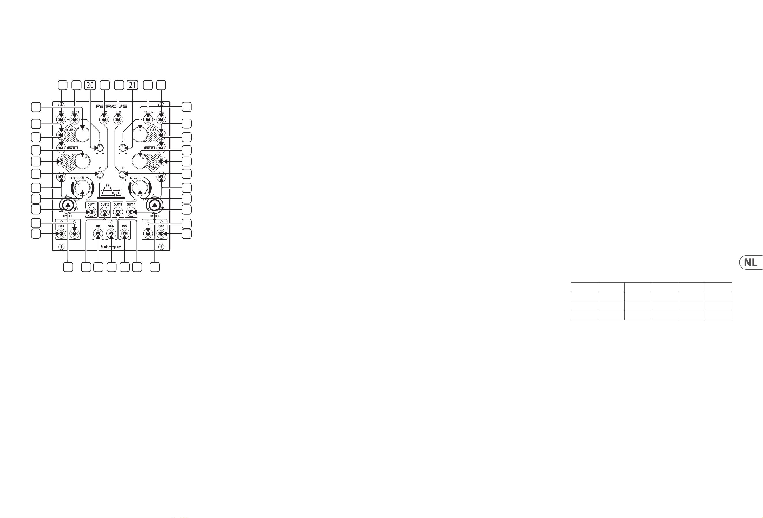
24 ABACUS Quick Start Guide 25
ABACUS Bediening
(NL)
Bediening
1. CHANNEL 1 CV INPUT – Accepteert variabele spanning over een bereik van
+/– 10 V voor verwerking door kanaal 1. Als er geen spanning aanwezig is,
gebruikt de Abacus een zelf gegenereerde spanning van ongeveer +10 V.
2. CHANNEL 1 TRIGGER INPUT – Accepteert een positieve gate of trigger
boven + 2.5 V. Activeert de functie Rise/Fall.
3. CHANNEL 2 CV INPUT – Accepteert spanning over een bereik van +/– 10 V
voor dempingsconversie via regelaar 20.
4. CHANNEL 3 CV INPUT – Accepteert spanning over een bereik van +/– 10 V
voor dempingsconversie via regelaar 21.
5. CHANNEL 4 TRIGGER INPUT – Accepteert positieve gate of trigger boven
+ 2.5 V. Activeert de functie Rise/Fall.
6. CHANNEL 4 CV INPUT – Accepteert variabele spanning over een bereik van
+/- 10 V voor verwerking door kanaal 4. Als er geen spanning aanwezig is,
gebruikt de Abacus een zelf gegenereerde spanning van ongeveer +10 V.
7. CHANNEL 1 RISE CV INPUT – Geeft CV-controle over de functie Rise, in
combinatie met regelaar 8. Accepteert spanning in een bereik van +/– 8 V.
Positieve spanning verlengt de Rise-tijd totdat het maximum is bereikt;
negatieve spanning verkort de Rise-tijd, totdat deze het minimum bereikt.
8. CHANNEL 1 RISE TIME – Gebruik deze regelaar om de Rise-tijd in te
stellen. Zie onderstaande tabel voor meer informatie over de maximale
tijden, afhankelijk van de instellingen. Kan verder worden gemoduleerd
door een CV naar aansluiting 7 te sturen.
9. CHANNEL 4 RISE TIME – Gebruik deze regelaar om de Rise-tijd in te
stellen. Zie onderstaande tabel voor meer informatie over de maximale
tijden, afhankelijk van de instellingen. Kan verder worden gemoduleerd
door een CV naar aansluiting 10 te sturen.
10. CHANNEL 4 RISE CV INPUT – Maakt CV-besturing mogelijk voor de
functie Rise, in combinatie met regelaar 9. Accepteert spanning in een
bereik van +/– 8 V. Positieve spanning verlengt de Rise-tijd totdat het
maximum is bereikt; negatieve spanning verkort de Rise-tijd, totdat deze
het minimum bereikt.
11. CHANNEL 1 BOTH CV INPUT – Accepteert een spanning in het bereik
+/- 8 V. Een positieve spanning verkort de totale tijd van Rise/Fall
exponentieel, totdat het minimum is bereikt; een negatieve spanning
verlengt de tijd exponentieel totdat deze het maximum bereikt.
12. CHANNEL 2 ATTENUVERTER – Gebruik deze regelaar om de via
ingang 3 naar kanaal 2 verstuurde voltages of de intern gegenereerde
voltages te verzwakken (naar rechts draaien) of te inverteren (naar links
draaien) over een bereik -10 V tot + 10 V.
13. CHANNEL 3 ATTENUVERTER – Gebruik deze regelaar om de via
ingang 4 naar kanaal 3 verstuurde voltages of de intern gegenereerde
voltages te verzwakken (naar rechts draaien) of te inverteren (naar links
draaien) over een bereik -5 V tot + 6 V.
14. CHANNEL 4 BOTH CV INPUT – Accepteert een spanning over een bereik
van +/– 8 V. Een positieve spanning verkort de totale tijd van Rise/Fall
exponentieel, totdat het minimum is bereikt; een negatieve spanning
verlengt de tijd exponentieel totdat deze het maximum bereikt.
15. CHANNEL 1 FALL CV INPUT – Geeft CV-controle over de Fall-functie, in
combinatie met regelaar 16. Accepteert spanning in een bereik van +/– 8 V.
Positieve spanning verlengt de Fall-tijd totdat het maximum is bereikt;
negatieve spanning verkort de Fall-tijd, totdat deze het minimum bereikt.
16. CHANNEL 1 FALL TIME – Gebruik deze regelaar om de Fall-tijd in te
stellen. Zie onderstaande tabel voor meer informatie over de maximale
tijden, afhankelijk van de instellingen. Kan verder worden gemoduleerd
door een CV naar aansluiting 15 te sturen.
17. CHANNEL 4 FALL TIME – Gebruik deze regelaar om de Fall-tijd in te
stellen. Zie onderstaande tabel voor meer informatie over de maximale
tijden, afhankelijk van de instellingen. Kan verder worden gemoduleerd
door een CV naar aansluiting 18 te sturen.
18. CHANNEL 4 FALL CV INPUT – Maakt CV-besturing mogelijk voor de
functie Fall, in combinatie met regelaar 17. Accepteert spanning in een
bereik van +/– 8 V. Positieve spanning verlengt de Fall-tijd totdat het
maximum is bereikt; negatieve spanning verkort de Fall-tijd, totdat deze
het minimum bereikt.
19. CHANNEL 1 CYCLE TRIGGER – Zorgt voor een externe positieve gate of
trigger van +2.5 V of meer om de cycle-functie van kanaal 1 te activeren.
20. CHANNEL 1 ATTENUVERTER – Gebruik deze regelaar om de uitgang van
kanaal 1 na de verwerking van Rise/Fall te dempen (naar rechts draaien) of
te inverteren (naar links draaien). Geeft geen interne spanning door totdat
de verwerking plaatsvindt.
21. CHANNEL 4 ATTENUVERTER – Gebruik deze regelaar om de uitgang van
kanaal 4 na de verwerking van Rise/Fall te dempen (naar rechts draaien) of
te inverteren (naar links draaien). Geeft geen interne spanning door totdat
de verwerking plaatsvindt.
22. CHANNEL 4 CYCLE TRIGGER – Zorgt voor een externe positieve gate of
trigger van +2.5 V of meer om de cycle-functie van kanaal 4 te activeren.
23. CHANNEL 1 RESPONSE – Gebruik deze regelaar om de respons van
kanaal 1 te variëren van logaritmisch tot lineair en exponentieel.
Zie de onderstaande tabel.
24. CHANNEL 4 RESPONSE – Gebruik deze regelaar om de respons van
kanaal 4 te variëren van logaritmisch tot lineair en exponentieel.
Zie de onderstaande tabel.
25. CHANNEL 1 CYCLE – Gebruik deze knop om het cyclen (roteren) van kanaal
1 te activeren; Rise en Fall roteren totdat de knop opnieuw wordt ingedrukt
om de cyclus te stoppen. Tijdens het roteren licht de knop op. De knop
knippert als cycle extern wordt getriggerd via ingang 19. De interne cyclus
krijgt prioriteit boven externe trigger.
26. CHANNEL 1 OUTPUT – Verzendt de verwerkte spanning van kanaal 1.
27. CHANNEL 2 OUTPUT – Verzendt de verwerkte spanning van kanaal 2.
28. CHANNEL 3 OUTPUT – Verzendt de verwerkte spanning van kanaal 3.
29. CHANNEL 4 OUTPUT – Verzendt de verwerkte spanning van kanaal 4.
30. CHANNEL 4 CYCLE – Gebruik deze knop om het cyclen (roteren) van kanaal
4 te activeren; Rise en Fall roteren totdat de knop opnieuw wordt ingedrukt
om de cyclus te stoppen. Tijdens het roteren licht de knop op. De knop
knippert als cycle extern wordt getriggerd via ingang 22. De interne cyclus
krijgt prioriteit boven externe trigger.
31. CHANNEL 1 END OF RISE OUTPUT – Stuurt op het hoogste punt van
de functie Rise een +9 V-spanning uit, die wordt aangegeven door de
bijbehorende LED, die actief blijft tot het einde van de Fall-cyclus.
32. CHANNEL 1 UNITY OUTPUT – Verzendt een spanning van 0 - +10 V na de
functies Rise/Fall als kanaal 1 cycelt (roteert); volgt anders de kanaalingang
die niet wordt beïnvloed door de dempingsconverter. LED geeft groen aan
voor een positieve spanning, rood voor een negatieve spanning.
33. OR OUTPUT – Stuurt het resultaat uit van een analoge OF-functie die is
gebaseerd op de instelling van de dempingsconverters voor kanaal 1 – 4
(regelaars 12, 13, 20, 21). Kanalen 1 en 4 hebben een externe spanning
nodig om mee te doen.
34. SUM OUTPUT – Stuurt een opgeteld (summed) voltage uit in het bereik
+/- 10 V op basis van de instellingen van de dempingsconverters voor
kanalen 1 – 4 (regelaars 12, 13, 20, 21). LED geeft groen aan voor een
positieve spanning, rood voor een negatieve spanning. Kanalen 1 en 4
hebben een externe spanning nodig om mee te doen.
35. INVERTED SUM OUTPUT – Verzendt de geïnverteerde versie van
SUM-uitgang 34.
36. CHANNEL 4 UNITY OUTPUT – Verzendt een spanning van 0 - +10 V
na de functies Rise/Fall als kanaal 4 cycelt (roteert); volgt anders de
kanaalaansluiting die niet wordt beïnvloed door de dempingsconverter.
LED geeft groen aan voor een positieve spanning, rood voor een
negatieve spanning.
37. CHANNEL 4 END OF CYCLE OUTPUT – Stuurt aan het einde van de
Rise/Fall cycle een + 9 V-spanning uit, die wordt aangegeven door de
bijbehorende LED.
Maximumaantal functietijden – kanaal 1 en kanaal 4
Regelaar(s) en dempingsconverter ingesteld op maximum (volledig naar
rechts draaien)
Rise-tijd Rise-piek Fall-Tijd Fall-min Cycletijd
Log 9 m 0 s 9.48 v 25 m 15 s 0.03 v 42 m 45 s
Lin 55 s 9.48 v 50 s 0.03 v 1 m 45 s
Exp 7 s 4.5 v 5 s 0.03 v 10 s
Hints en tips
• Kanalen 1 en 4 kunnen worden gebruikt om de functies Rise, Fall - afzonderlijk
of allebei - van elkaar te moduleren.
• De EOC-trigger van kanaal 4 kan worden gebruikt om een externe sample
& hold-generator te activeren die vervolgens als modulatiebron kan
worden gebruikt.
• De EOR-uitgang van kanaal 1 kan worden gebruikt als een modier voor elke
CV-ingang op kanaal 1 en 4; of als externe spanningsingang voor elk kanaal.
• Kanalen 2 en 3 kunnen worden gebruikt om een osetspanning te genereren
voor de CV-ingangen van kanaal 1 en 4.
• Experimenteer met de geïnverteerde somspanning als besturingsbron.
1
2
3
4
5 6
8
9
10
11
7
12
19
23
25
32
26 27 33 34 35 28 29
37
36
30
24
22
31
16
15
13
14
17
18
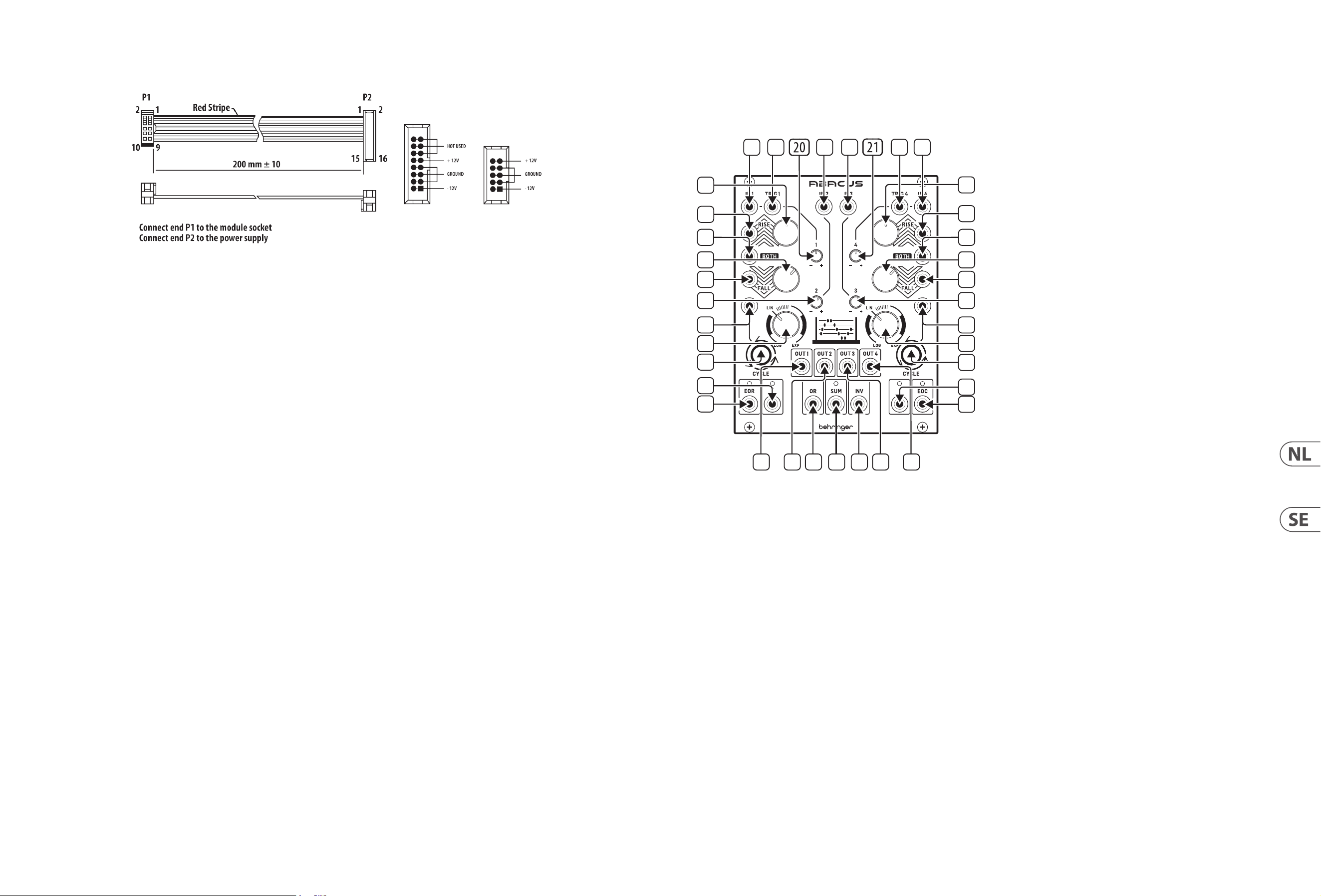
26 ABACUS Quick Start Guide 27
De module wordt geleverd met de benodigde voedingskabel voor aansluiting
op een standaard Eurorack-voedingssysteem. Volg deze stappen om de module
van stroom te voorzien. Het is gemakkelijker om deze aansluitingen te maken
voordat de module in een rekbehuizing is gemonteerd.
1. Schakel de voeding of de rekbehuizing uit en koppel de voedingskabel los.
2. Steek de 16-pins connector van de voedingskabel in de aansluiting op de
voedingseenheid of rekbehuizing. De connector heeft een lipje dat wordt
uitgelijnd met de opening in de socket, zodat deze niet verkeerd kan worden
geplaatst. Als de voeding geen contactdoos met sleutel heeft, zorg er dan
voor dat pen 1 (-12 V) met de rode streep op de kabel wordt georiënteerd.
3. Steek de 10-pins connector in de aansluiting aan de achterkant van de
module. De connector heeft een lipje dat uitgelijnd is met de aansluiting
voor de juiste oriëntatie.
4. Nadat beide uiteinden van de voedingskabel stevig zijn bevestigd, kunt u de
module in een hoesje monteren en de voeding inschakelen.
Installatie
De benodigde schroeven worden bij de module geleverd voor montage in een
Eurorack-koer. Sluit de voedingskabel aan voor montage.
Afhankelijk van de rackbehuizing kan er een reeks vaste gaten zijn die 2 HP uit
elkaar liggen over de lengte van de behuizing, of een rail waarmee afzonderlijke
platen met schroefdraad langs de lengte van de behuizing kunnen schuiven.
De vrij bewegende plaatjes met schroefdraad maken een nauwkeurige
positionering van de module mogelijk, maar elke plaat moet ongeveer in
verhouding tot de montagegaten in uw module worden geplaatst voordat u de
schroeven bevestigt.
Houd de module tegen de Eurorack-rails zodat elk van de montagegaten is
uitgelijnd met een rail met schroefdraad of een plaat met schroefdraad. Bevestig
de schroeven halverwege om te beginnen, waardoor kleine aanpassingen aan
de positionering mogelijk zijn terwijl u ze allemaal op één lijn krijgt. Nadat de
denitieve positie is bepaald, draait u de schroeven vast.
Stroomaansluiting
ABACUS Kontroller
(SE)
Kontroller
1. CHANNEL 1 CV INPUT – Tar emot variabla spänningar i intervallet +/- 10 V
för behandling av kanal 1. Om ingen spänning nns kommer Abacus att
använda en egengenererad spänning på ungefär +10 V.
2. CHANNEL 1 TRIGGER INPUT – Tar emot positivt riktad gate eller trigger
över + 2.5 V. Gör så att Rise/Fall-funktionen aktiveras.
3. CHANNEL 2 CV INPUT – Tar emot spänningar i intervallet +/- 10 V för
attenuvertering av kontroll 20.
4. CHANNEL 3 CV INPUT – Tar emot spänningar i intervallet +/- 10 V för
attenuvertering av kontroll 21.
5. CHANNEL 4 TRIGGER INPUT – Tar emot positivt riktad gate eller trigger
över + 2.5 V. Gör så att Rise/Fall-funktionen aktiveras.
6. CHANNEL 4 CV INPUT – Tar emot variabla spänningar i intervallet +/- 10 V
för behandling av kanal 4. Om ingen spänning nns kommer Abacus att
använda en egengenererad spänning på ungefär +10 V.
7. CHANNEL 1 RISE CV INPUT – Möjliggör CV-styrning av Rise-funktionen,
tillsammans med kontroll 8. Tar emot spänningar i intervallet +/- 8 V.
Positiva spänningar ökar Rise-tiden tills maximum har nåtts; negativa
spänningar minskar den tills den når minimum.
8. CHANNEL 1 RISE TIME – Använd denna kontroll för att ställa in Rise-tiden.
Se tabell nedan för maximala tider enligt olika inställningar. Kan moduleras
vidare genom matning av en CV till uttag 7.
9. CHANNEL 4 RISE TIME – Använd denna kontroll för att ställa in Rise-tiden.
Se tabell nedan för maximala tider enligt olika inställningar. Kan moduleras
vidare genom matning av en CV till uttag 10.
10. CHANNEL 4 RISE CV INPUT – Möjliggör CV-styrning av Rise-funktionen,
tillsammans med kontroll 9. Tar emot spänningar i intervallet +/- 8 V.
Positiva spänningar ökar Rise-tiden tills maximum har nåtts; negativa
spänningar minskar den tills den når minimum.
11. CHANNEL 1 BOTH CV INPUT – tar emot en spänning i intervallet
+/- 8 V. En positiv spänning kommer att exponentiellt minska den
totala Rise/Fall-tiden tills minimum nås; en negativ spänning ökar den
exponentiellt tills den når maximum.
12. CHANNEL 2 ATTENUVERTER – Använd denna kontroll för att dämpa
(medurs) eller invertera (moturs) spänningar som skickas till kanal
2-ingången på uttag 3 eller den internt genererade spänningen i intervallet
-10 V till + 10 V.
13. CHANNEL 3 ATTENUVERTER – Använd denna kontroll för att dämpa
(medurs) eller invertera (moturs) spänningar som skickas till kanal
3-ingången på uttag 4 eller den internt genererade spänningen i intervallet
-5 V till + 6 V.
14. CHANNEL 4 BOTH CV INPUT – Tar emot en spänning i intervallet
+/- 8 V. En positiv spänning kommer att exponentiellt minska den
totala Rise/Fall-tiden tills minimum nås; en negativ spänning ökar den
exponentiellt tills den når maximum.
1
2
3
4
5 6
8
9
10
11
7
12
19
23
25
32
26 27 33 34 35 28 29
37
36
30
24
22
31
16
15
13
14
17
18
28 ABACUS Quick Start Guide 29
15. CHANNEL 1 FALL CV INPUT – Möjliggör CV-styrning av Fall-funktionen,
tillsammans med kontroll 16. Tar emot spänningar i intervallet +/- 8 V.
Positiva spänningar ökar Fall-tiden tills maximum har nåtts; negativa
spänningar minskar den tills den når minimum.
16. CHANNEL 1 FALL TIME – Använd denna kontroll för att ställa in Fall-tiden.
Se tabell nedan för maximala tider enligt olika inställningar. Kan moduleras
vidare genom matning av en CV till uttag 15.
17. CHANNEL 4 FALL TIME – Använd denna kontroll för att ställa in Fall-tiden.
Se tabell nedan för maximala tider enligt olika inställningar. Kan moduleras
vidare genom matning av en CV till uttag 18.
18. CHANNEL 4 FALL CV INPUT – Möjliggör CV-styrning av Fall-funktionen,
tillsammans med kontroll 17. Tar emot spänningar i intervallet +/- 8 V.
Positiva spänningar ökar Fall-tiden tills maximum har nåtts; negativa
spänningar minskar den tills den når minimum.
19. CHANNEL 1 CYCLE TRIGGER – Gör det möjligt för en extern positivt riktad
gate eller trigger på +2.5 V eller mer att trigga kanal 1:s Cycle-funktion.
20. CHANNEL 1 ATTENUVERTER – Använd denna kontroll för att dämpa
(medurs) eller invertera (moturs) utsignalen från kanal 1 efter Rise/Fall-
behandling. Förmedlar inte intern spänning om inte behandling sker.
21. CHANNEL 4 ATTENUVERTER – Använd denna kontroll för att dämpa
(medurs) eller invertera (moturs) utsignalen från kanal 4 efter Rise/Fall-
behandling. Förmedlar inte intern spänning om inte behandling sker.
22. CHANNEL 4 CYCLE TRIGGER – Gör det möjligt för en extern positivt riktad
gate eller trigger på +2.5 V eller mer att trigga kanal 4:s Cycle-funktion.
23. CHANNEL 1 RESPONSE – Använd denna kontroll för att variera responsen
för kanal 1 från logaritmisk via linjär till exponentiell. Se tabell nedan.
24. CHANNEL 4 RESPONSE – Använd denna kontroll för att variera responsen
för kanal 4 från logaritmisk via linjär till exponentiell. Se tabell nedan.
25. CHANNEL 1 CYCLE – Använd den här knappen för att initiera alternering
för kanal 1; Rise och Fall kommer att alternera tills knapp trycks in igen för
att stoppa alterneringen. Knappen lyser vid alternering. Knappen blinkar
när Cycle triggas externt via uttag 19. Intern Cycle prioriteras framför
extern trigger.
26. CHANNEL 1 OUTPUT – Skickar ut den behandlade spänningen från kanal 1.
27. CHANNEL 2 OUTPUT – Skickar ut den behandlade spänningen från kanal 2.
28. CHANNEL 3 OUTPUT – Skickar ut den behandlade spänningen från kanal 3.
29. CHANNEL 4 OUTPUT – Skickar ut den behandlade spänningen från kanal 4.
30. CHANNEL 4 CYCLE – Använd den här knappen för att initiera alternering
för kanal 4; Rise och Fall kommer att alternera tills knapp trycks in igen för
att stoppa alterneringen. Knappen lyser vid alternering. Knappen blinkar
när Cycle triggas externt via uttag 22. Intern alternering prioriteras framför
extern trigger.
31. CHANNEL 1 END OF RISE OUTPUT – Skickar ut en + 9 V-spänning på
toppen av Rise-funktionen, vilket indikeras av den tillhörande lysdioden,
som fortsätter att vara aktiv till slutet av Fall-cykeln.
32. CHANNEL 1 UNITY OUTPUT – Skickar ut en 0 – +10 V- spänning som följer
Rise/Fall-funktionerna när kanal 1 alternerar; följer annars kanalinsignalen
opåverkad av attenuvertern. Lysdioden lyser grönt för en positiv spänning,
röd för en negativ.
33. OR OUTPUT – Skickar ut resultatet av en analog OR-funktion baserat på
inställningen av attenuvertrarna för kanal 1–4 (kontroll 12, 13, 20, 21).
Kanal 1 och 4 behöver en extern spänning för att inkluderas.
34. SUM OUTPUT – Skickar ut en summerad spänning i i ntervallet +/- 10 V
baserat på inställningen av attenuvertrarna för kanal 1–4 (kontroll 12, 13,
20, 21). Lysdioden lyser grönt för en positiv spänning, röd för en negativ.
Kanal 1 och 4 behöver en extern spänning för att inkluderas.
35. INVERTED SUM OUTPUT – Skickar ut inverteringen av Sum-utgång 34.
36. CHANNEL 4 UNITY OUTPUT – Skickar ut en 0 – +10 V-spänning som följer
Rise/Fall-funktionerna när kanal 4 alternerar; följer annars kanalinsignalen
opåverkad av attenuvertern. Lysdioden lyser grönt för en positiv spänning,
röd för en negativ.
37. CHANNEL 4 END OF CYCLE OUTPUT - Skickar ut en + 9 V-spänning
i slutet av Rise/Fall-cykeln, vilket indikeras av den tillhörande
lysdioden.
Maximala funktionstider – kanal 1 och kanal 4
Kontroll(er) och attenuverter inställda på maximum (helt medurs)
Rise-tid Rise-topp Fall-tid Fall-min. Cykeltid
Log 9 m 0 s 9.48 v 25 m 15 s 0.03 v 42 m 45 s
Lin 55 s 9.48 v 50 s 0.03 v 1 m 45 s
Exp 7 s 4.5 v 5 s 0.03 v 10 s
Tips
• Kanal 1 och 4 kan användas för att modulera varandras Rise-, Fall- eller
Both-funktioner.
• Kanal 4:s EOC-trigger kan användas för att trigga en extern Sample and
Hold-generator som sedan kan användas som en modulationskälla.
• Kanal 1:s EOR-utsignal kan användas som en modierare till valfri CV-ingång
på kanal 1 och 4, eller som en extern spänningsinmatning till valfri kanal.
• Kanal 2 och 3 kan användas för att tillhandahålla en osetspänning för
CV-ingångarna för kanal 1 och 4.
• Experimentera med den inverterade summeringsspänningen som en styrkälla.
Modulen levereras med den strömkabel som krävs för att ansluta till ett vanligt
Eurorack-nätaggregat. Följ dessa steg för att ansluta ström till modulen. Det är
lättare att göra dessa anslutningar innan modulen har monterats i ett rackfodral.
1. Stäng av strömmen eller rackhöljet och koppla bort strömkabeln.
2. Sätt i den 16-poliga kontakten på strömkabeln i uttaget på nätaggregatet
eller rackfodralet. Kontaktdonet har en ik som kommer i linje med springan
i uttaget så att den inte kan sättas in felaktigt. Om strömförsörjningen inte
har ett nyckeluttag, se till att orientera stift 1 (-12 V) med den röda remsan
på kabeln.
3. Sätt i 10-polig kontakt i uttaget på baksidan av modulen. Kontaktdonet har
en ik som kommer i linje med uttaget för korrekt orientering.
4. När båda ändarna av strömkabeln har anslutits ordentligt kan du montera
modulen i ett fodral och slå på strömförsörjningen.
Installation
De nödvändiga skruvarna ingår i modulen för montering i ett Eurorack-fodral.
Anslut strömkabeln före montering.
Beroende på stativhöljet kan det nnas en serie fasta hål som är åtskilda 2
hk längs höljets längd eller ett spår som gör att enskilda gängade plattor kan
glida längs höljets längd. De fritt rörliga gängade plattorna möjliggör exakt
positionering av modulen, men varje platta bör placeras i ungefärlig relation till
monteringshålen i din modul innan skruvarna fästs.
Håll modulen mot Eurorack-skenorna så att var och en av monteringshålen ligger
i linje med en gängad skena eller gängad platta. Fäst skruvarna delvis för att
börja, vilket gör det möjligt att justera små positioner medan du justerar dem
alla. När den slutliga positionen har fastställts drar du åt skruvarna.
Strömanslutning
ABACUS Kontroller
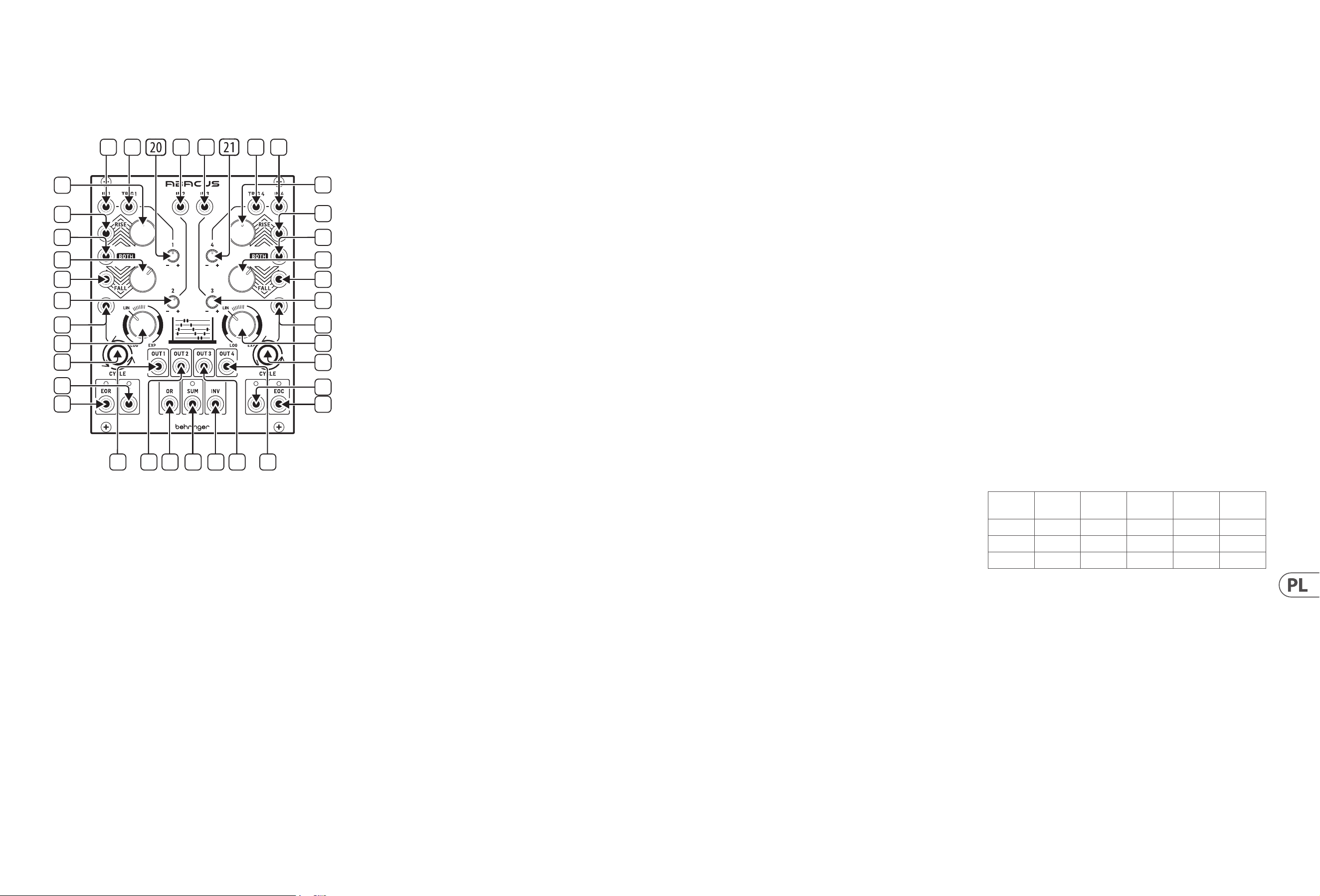
30 ABACUS Quick Start Guide 31
ABACUS Sterowanica
(PL)
Sterowanica
1. CHANNEL 1 CV INPUT – Przyjmuje zmienne napięcia w przedziale +/- 10 V
do przetworzenia przez kanał 1. Jeśli nie występuje napięcie, Abacus sam
wygeneruje napięcie o wartości ok. + 10 V.
2. CHANNEL 1 TRIGGER INPUT – Przyjmuje każdy sygnał gate lub trigger
o kierunku dodatnim powyżej +2.5 V. Powoduje aktywację funkcji
narastania/opadania (Rise/Fall).
3. CHANNEL 2 CV INPUT – Przyjmuje napięcia w przedziale +/- 10 V do
redukcji/odwrócenia („attenuverting”) przez pokrętło 20.
4. CHANNEL 3 CV INPUT – Przyjmuje napięcia w przedziale +/- 10 V do
redukcji/odwrócenia („attenuverting”) przez pokrętło 21.
5. CHANNEL 4 TRIGGER INPUT – Przyjmuje każdy sygnał gate lub trigger
o kierunku dodatnim powyżej +2.5 V. Powoduje aktywację funkcji
narastania/opadania (Rise/Fall).
6. CHANNEL 4 CV INPUT – Przyjmuje zmienne napięcia w przedziale
+/- 10 V do przetworzenia przez kanał 4. Jeśli nie występuje napięcie,
Abacus sam wygeneruje napięcie o wartości ok. + 10 V.
7. CHANNEL 1 RISE CV INPUT – Pozwala na kontrolę funkcji Rise za
pomocą napięcia CV, w połączeniu z pokrętłem 8. Przyjmuje napięcia w
przedziale +/- 8 V. Dodatnie napięcia zwiększają czas narastania (Rise)
aż do osiągnięcia maksimum; ujemne napięcia redukują czas, aż osiągnie
minimum.
8. CHANNEL 1 RISE TIME – Użyj tego pokrętła, aby ustawić czas funkcji
narastania (Rise). Patrz tabela poniżej dla najdłuższego czasu według
różnych ustawień. Możliwa jest dalsza modulacja przesyłając napięcie
CV do wejścia 7.
9. CHANNEL 4 RISE TIME – Użyj tego pokrętła, aby ustawić czas funkcji
narastania (Rise). Patrz tabela poniżej dla najdłuższego czasu według
różnych ustawień. Możliwa jest dalsza modulacja przesyłając napięcie
CV do wejścia 10.
10. CHANNEL 4 RISE CV INPUT – Pozwala na kontrolę funkcji narastania (Rise)
za pomocą napięcia CV, w połączeniu z pokrętłem 9. Przyjmuje napięcia
w przedziale +/- 8 V. Dodatnie napięcia zwiększają czas narastania (Rise)
aż do osiągnięcia maksimum; ujemne napięcia redukują czas, aż osiągnie
minimum.
11. CHANNEL 1 BOTH CV INPUT – Przyjmuje napięcie w przedziale +/- 8 V.
Dodatnie napięcie wykładniczo zredukuje ostateczny czas opadania/
narastania (Rise/Fall) aż do osiągnięcia minimum; napięcie ujemne
wykładniczo zwiększa czas, aż do osiągnięcia maksimum.
12. CHANNEL 2 ATTENUVERTER – Użyj tego pokrętła, aby zredukować
(w prawo) lub odwrócić (w lewo) napięcia przesyłane do wejścia kanału 2
na wejściu 3 lub wewnętrznie generowane napięcie w przedziale od -10 V
do + 10 V.
13. CHANNEL 3 ATTENUVERTER – Użyj tego pokrętła, aby zredukować
(w prawo) lub odwrócić (w lewo) napięcia przesyłane do wejścia kanału 3
na wejściu 4 lub wewnętrznie generowane napięcie w przedziale od -10 V
do + 10 V.
14. CHANNEL 4 BOTH CV INPUT – Przyjmuje napięcie w przedziale +/- 8 V.
Dodatnie napięcie wykładniczo zredukuje ostateczny czas opadania/
narastania (Rise/Fall) aż do osiągnięcia minimum; napięcie ujemne
wykładniczo zwiększa czas, aż do osiągnięcia maksimum.
15. CHANNEL 1 FALL CV INPUT – Pozwala na kontrolę funkcji opa dania
(Fall) za pomocą napięcia CV, w połączeniu z pokrętłem 16. Przyjmuje
napięcia w przedziale +/- 8 V. Dodatnie napięcia zwiększają czas opadania
(Fall) aż do osiągnięcia maksimum; ujemne napięcia redukują czas,
aż osiągnie minimum.
16. CHANNEL 1 FALL TIME – Użyj tego pokrętła, aby ustawić czas opadania
(Fall). Patrz tabela poniżej dla maksymalnego czasu w zależności od
różnych ustawień. Może być dodatkowo modulowany przesyłając napięcie
CV do wejścia 15.
17. CHANNEL 4 FALL TIME – Użyj tego pokrętła, aby ustawić czas opadania
(Fall). Patrz tabela poniżej dla maksymalnego czasu w zależności od
różnych ustawień. Może być dodatkowo modulowany przesyłając napięcie
CV do wejścia 18.
18. CHANNEL 4 FALL CV INPUT – Pozwala na kontrolę funkcji opadania
(Fall) za pomocą napięcia CV, w połączeniu z pokrętłem 17. Przyjmuje
napięcia w przedziale +/- 8 V. Dodatnie napięcia zwiększają czas opadania
(Fall) aż do osiągnięcia maksimum; ujemne napięcia redukują czas, aż
osiągnie minimum.
19. CHANNEL 1 CYCLE TRIGGER – Pozwala zewnętrznemu sygnałowi gate lub
trigger o kierunku dodatnim i wartości +2.5 V lub większej na aktywację
funkcji Cycle kanału 1.
20. CHANNEL 1 ATTENUVERTER – Użyj tej regulacji w celu redukcji (w prawo)
lub odwrócenia (w lewo) sygnału wyjściowego kanału 1 po procesie Rise/
Fall. Nie przechodzi przez napięcie wewnętrzne, chyba że sygnał jest
przetwarzany.
21. CHANNEL 4 ATTENUVERTER – Użyj tej regulacji w celu redukcji (w prawo)
lub odwrócenia (w lewo) sygnału wyjściowego kanału 4 po procesie
Rise/Fall. Nie przechodzi przez napięcie wewnętrzne, chyba że sygnał
jest przetwarzany.
22. CHANNEL 4 CYCLE TRIGGER – Pozwala zewnętrznemu sygnałowi gate lub
trigger o kierunku dodatnim i wartości +2.5 V lub większej na aktywację
funkcji Cycle kanału 4.
23. CHANNEL 1 RESPONSE – Użyj tego pokrętła, aby ustawić charakterystykę
reakcji kanału 1 od logarytmicznej, przez liniową aż do wykładniczej.
Patrz tabela niżej.
24. CHANNEL 4 RESPONSE – Użyj tego pokrętła, aby ustawić charakterystykę
reakcji kanału 4 od logarytmicznej, przez liniową aż do wykładniczej.
Patrz tabela niżej.
25. CHANNEL 1 CYCLE – Użyj tego przycisku, aby uruchomić cykl (Cycle)
kanału 1 – narastanie (Rise) i opadanie (Fall) będą powtarzać się cyklicznie,
aż do zatrzymania przez ponowne wciśnięcie przycisku. Przycisk jest
podświetlony, gdy cykl jest włączony. Przycisk miga, gdy cykl został
aktywowany zewnętrznie przez wejście 19. Wewnętrzny cykl ma wyższy
priorytet, niż aktywacja zewnętrzna.
26. CHANNEL 1 OUTPUT – Wyjście przetworzonego napięcia z kanału 1.
27. CHANNEL 2 OUTPUT – Wyjście przetworzonego napięcia z kanału 2.
28. CHANNEL 3 OUTPUT – Wyjście przetworzonego napięcia z kanału 3.
29. CHANNEL 4 OUTPUT – Wyjście przetworzonego napięcia z kanału 4.
30. CHANNEL 4 CYCLE – Użyj tego przycisku, aby uruchomić cykl (Cycle)
kanału 4 – narastanie (Rise) i opadanie (Fall) będą powtarzać się cyklicznie,
aż do zatrzymania przez ponowne wciśnięcie przycisku. Przycisk jest
podświetlony, gdy cykl jest włączony. Przycisk miga, gdy cykl został
aktywowany zewnętrznie przez wejście 22. Wewnętrzny cykl ma wyższy
priorytet, niż aktywacja zewnętrzna.
31. CHANNEL 1 END OF RISE OUTPUT – Wysyła napięcie + 9 V na szczycie
funkcji narastania (Rise) wskazywane przez powiązaną diodę, które
pozostaje aktywne aż do końca cyklu opadania (Fall).
32. CHANNEL 1 UNITY OUTPUT – Wysyła napięcie 0 - +10 V podążając za
funkcjami Rise/Fall gdy kanał 1 jest w trybie cyklu; w innym wypadku
podąża za wyjściem kanału bez przetworzenia „attenuvertererem” (bez
redukcji/odwrócenia). Dioda świeci na zielono w przypadku napięcia
dodatniego lub na czerwono w przypadku ujemnego.
33. OR OUTPUT – Wysyła wynik analogowej funkcji OR oparty na ustawieniach
attenuverterów dla kanałów 1-4 (pokrętła 12, 13, 20, 21). Kanały 1 i 4
potrzebują napięcia zewnętrznego, aby były włączone.
34. SUM OUTPUT – Wysyła zsumowane napięcie w przedziale +/- 10 V w
zależności od ustawień attenuverterów dla kanałów 1-4 (pokrętła 12,
13, 20, 21). Dioda świeci na zielono w przypadku napięcia dodatniego lub
na czerwono w przypadku ujemnego. Kanały 1 i 4 potrzebują napięcia
zewnętrznego, aby były włączone.
35. INVERTED SUM OUTPUT – Wysyła odwrotność wyjścia sumy (34).
36. CHANNEL 4 UNITY OUTPUT – Wysyła napięcie 0 - +10 V podążając za
funkcjami Rise/Fall gdy kanał 4 jest w trybie cyklu; w innym wypadku
podąża za wyjściem kanału bez przetworzenia „attenuvertererem” (bez
redukcji/odwrócenia). Dioda świeci na zielono w przypadku napięcia
dodatniego lub na czerwono w przypadku ujemnego.
37. CHANNEL 4 END OF CYCLE OUTPUT – Wysyła napięcie + 9 V na końcu
cyklu narastania/opadania (Rise/Fall), wskazywane przez powiązaną diodę.
Maksymalne czasy funkcji – kanał 1 i kanał 4
Pokrętła oraz Attenuverter ustawione na maksimum (całkowicie w prawo)
Czas
narastania
Szczyt
narastania
Czas
opadania
Minimum
opadania
Czas
cyklu
Log 9 m 0 s 9.48 v 25 m 15 s 0.03 v 42 m 45 s
Lin 55 s 9.48 v 50 s 0.03 v 1 m 45 s
Exp 7 s 4.5 v 5 s 0.03 v 10 s
Podpowiedzi i sugestie
• Kanały 1 i 4 mogą być używane do wzajemnej modulacji funkcji Rise
(narastanie), Fall (opadanie) lub Both (obydwa).
• Sygnał trigger EOC (końca cyklu) kanału 4 może być użyty do wzbudzenia
zewnętrznego generatora Sample & Hold, który może być następnie użyty
jako źródło modulacji.
• Wyjście EOR (końca narastania) kanału 1 może być użyte jako modykator
dowolnego wejścia CV na kanałach 1 i 4, lub jako wejście zewnętrznego
napięcia na dowolnym kanale.
• Kanały 2 i 3 mogą być użyte w celu dostarczenia napięcia równoważącego dla
wejść CV kanałów 1 i 4.
• Eksperymentuj z odwróconą sumą napięć jako źródła kontroli.
1
2
3
4
5 6
8
9
10
11
7
12
19
23
25
32
26 27 33 34 35 28 29
37
36
30
24
22
31
16
15
13
14
17
18
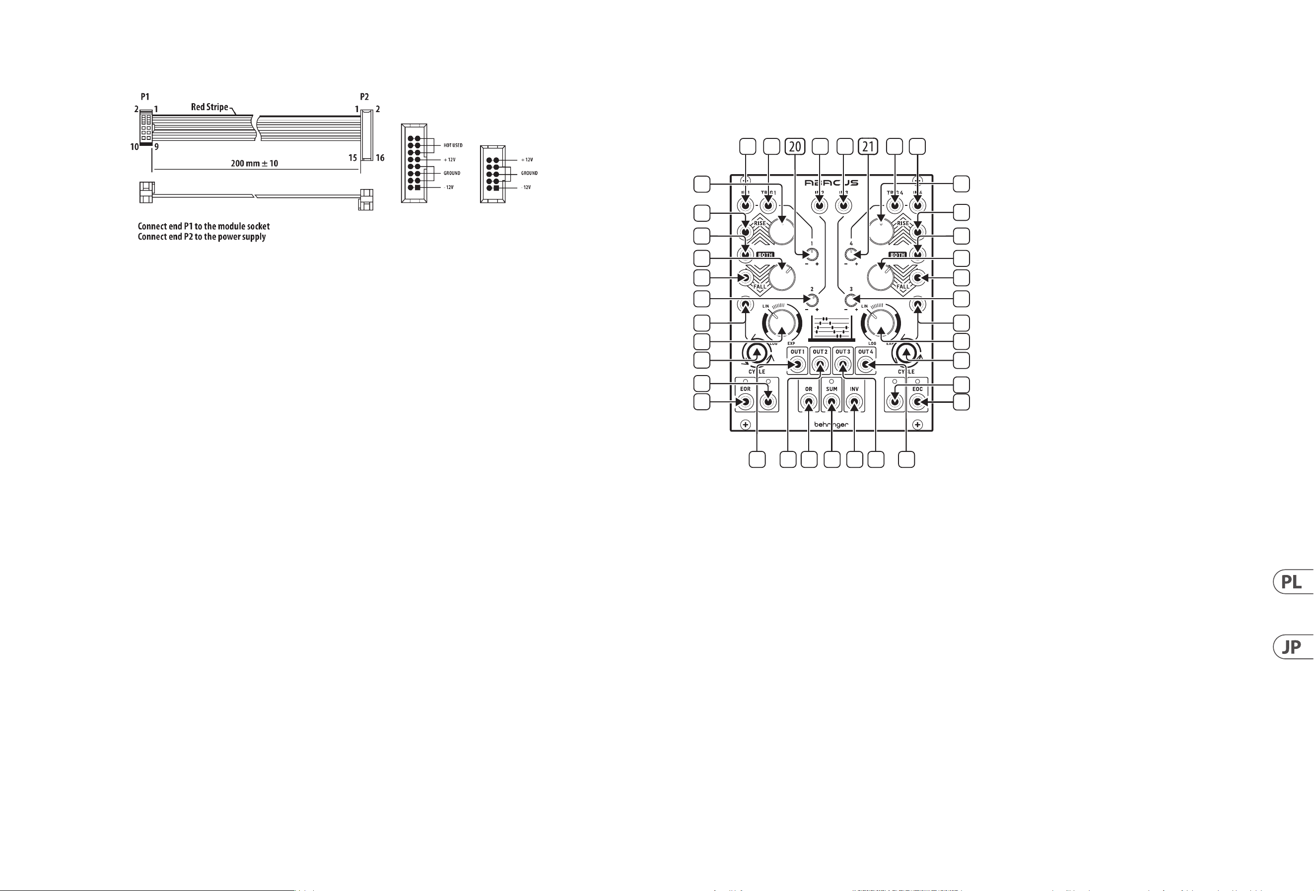
32 ABACUS Quick Start Guide 33
Do modułu dołączony jest wymagany kabel zasilający do podłączenia do
standardowego systemu zasilania Eurorack. Wykonaj poniższe czynności,
aby podłączyć zasilanie do modułu. Łatwiej jest wykonać te połączenia przed
zamontowaniem modułu w obudowie rack.
1. Wyłącz zasilacz lub obudowę szafy i odłącz kabel zasilający.
2. Włóż 16-stykowe złącze przewodu zasilającego do gniazda w zasilaczu lub w
szae typu rack. Złącze ma wypustkę, która będzie wyrównana ze szczeliną
w gnieździe, więc nie można jej nieprawidłowo włożyć. Jeśli zasilacz nie ma
gniazda z kluczem, należy zorientować styk 1 (-12 V) z czerwonym paskiem
na kablu.
3. Włóż 10-pinowe złącze do gniazda z tyłu modułu. Złącze ma wypustkę,
która będzie wyrównana z gniazdem, aby zapewnić prawidłową orientację.
4. Po solidnym zamocowaniu obu końców kabla zasilającego można
zamontować moduł w obudowie i włączyć zasilacz.
Instalacja
Do modułu dołączone są niezbędne śruby do montażu w skrzynce Eurorack.
Podłącz kabel zasilający przed montażem.
W zależności od obudowy szafy może występować szereg stałych otworów
rozmieszczonych w odstępach 2 HP na całej długości obudowy lub prowadnica,
która umożliwia przesuwanie pojedynczych gwintowanych płyt wzdłuż całej
obudowy. Swobodnie poruszające się gwintowane płytki umożliwiają precyzyjne
ustawienie modułu, ale każda płyta powinna być ustawiona w przybliżeniu w
stosunku do otworów montażowych w module przed przykręceniem śrub.
Przytrzymaj moduł na szynach Eurorack, tak aby każdy z otworów montażowych
był wyrównany z szyną gwintowaną lub płytą gwintowaną. Wkręć śruby
częściowo, aby rozpocząć, co pozwoli na drobne korekty położenia, gdy wszystkie
zostaną wyrównane. Po ustaleniu ostatecznego położenia dokręcić śruby.
Podłączenie Zasilania
ABACUS コントロール
(JP)
コントロール
1. CHANNEL 1 CV INPUT – チャンネル 1 で処 理する、+/- 10 V の範囲
の可変ボルテージを受け入れます。ボルテージが存在しない
場 合は、Abacus 自身が生成した約 +10 V のボルテージを使用
します。
2. CHANNEL 1 TRIGGER INPUT – + 2.5 V 以 上の立ち上 がりゲートまた
はトリガーを受け入れます。Rise/Fall 機能を有効化します。
3. CHANNEL 2 CV INPUT – コントロール 20 でアッテネート/反転す
る、+/- 10 V のボ ルテ ージ を 受 け入れ ま す。
4. CHANNEL 3 CV INPUT – コントロール 21 でアッテネート/反転す
る、+/- 10 V のボ ルテ ージ を 受 け入れ ま す。
5. CHANNEL 4 TRIGGER INPUT – + 2.5 V 以 上の立ち上 がりゲートまた
はトリガーを受け入れます。Rise/Fall 機能を有効化します。
6. CHANNEL 4 CV INPUT – チャンネル 4 で処 理する、+/- 10 V の範囲
の可変ボルテージを受け入れます。ボルテージが存在しない
場合は、Abacus 自身 が生 成した約 +10 V のボルテージを使用
します。
7. CHANNEL 1 RISE CV INPUT – コントロール 8 と使用し、Rise 機能
を CV 制 御します。+/- 8 V の 範 囲のボ ルテ ージ に 対 応します。
立ち上がりボルテージで、Rise タイムを最長に達するまで上
げ ます; 立ち下がりボルテージで、Rise タイム が 最 短 に 至 るま
で 下げ ます。
8. CHANNEL 1 RISE TIME – Rise タイムを設定するコントロールです。
設 定ごとの最 長タイムは 、下の表をご 参 照ください 。CV をソケ
ット7にフィードしてさらなるモジュレートが 可能です。
9. CHANNEL 4 RISE TIME – Rise タ イ ム を 制 御 し ま す 。設 定 ご と の 最
長タイムは下の表をご参照ください。CV をソケ ット 10 にフィ
ードして、さらにモジュレートできます。
10. CHANNEL 4 RISE CV INPUT – コントロール 9 と使用し、Rise 機能
を CV 制 御します。+/- 8 V の 範 囲のボ ルテ ージ に 対 応します。
立ち上がりボルテージで、Rise タイムを最長に達するまで上
げ ます; 立ち下がりボルテージで、Rise タイム が 最 短 に 至 るま
で 下げ ます。
11. CHANNEL 1 BOTH CV INPUT – +/- 8 V の範囲のボルテージを受け
入 れ ま す。立 ち 上 が り ボ ル テ ー ジ は 、Rise/Fall のトータル タイ
ムを最短に至るまで指数関数的に下げます; 立ち下がりボル
テージは、Rise/Fall のトータルタイムが最長に達するまで指数
関 数 的 に 上げ ます。
12. CHANNEL 2 ATTENUVERTER – ソケット 3 のチャンネル 2 入力にフ
ィードするボルテージ、または内部で生成したボルテージを
-10 V 〜 + 10 V の範 囲でアッテネート (時計回り方向)、ま た は
反転 (反時計回り方向) します。
13. CHANNEL 3 ATTENUVERTER – ソケット 4 のチャンネル 3 入力にフ
ィードするボルテージ、または内部で生成したボルテージを
-5 V 〜 + 6 V の範囲でアッテネート (時計回り方向)、ま た は 反
転 (反時計回り方向) します。
14. CHANNEL 4 BOTH CV INPUT – +/- 8 V の範囲のボルテージを受け
入 れ ま す。立 ち 上 が り ボ ル テ ー ジ は 、Rise/Fall タイムを 最 短 に
至るまで下げます; 立ち下がりボルテージでは最長に達する
まで上げ ます。
15. CHANNEL 1 FALL CV INPUT – コントロール 16と使用することで
Fall 機能を CV コントロ ールします。+/- 8 V の範囲のボルテージ
を受け入れます。立ち上がりボルテージで、Fall タイムを 最 長
に 達 す る ま で 上 げ 、立 ち 下 が り ボ ル テ ー ジ で 、Fall タイム が 最
短に 至るまで 下 げ ます。
1
2
3
4
5 6
8
9
10
11
7
12
19
23
25
32
26 27 33 34 35 28 29
37
36
30
24
22
31
16
15
13
14
17
18
34 ABACUS Quick Start Guide 35
16. CHANNEL 1 FALL TIME – Fall タイムを設定するコントロールです。
設 定ごとの最 長タイムは 、下の表をご 参 照ください 。CV をソケ
ット 15 にフィードしてさらなるモジュレートが 可能です。
17. CHANNEL 4 FALL TIME – Fall タイムを設定するコントロールです。
設 定ごとの最 長タイムは 、下の表をご 参 照ください 。CV をソケ
ット 18 にフィードしてさらにモジュレート可能 です。
18. CHANNEL 4 FALL CV INPUT – コントロール 17 と使用し、Fall 機能
を CV 制御し ます。+/- 8 V の 範 囲 のボ ルテ ージ を 受け入れま
す。立 ち 上 が り ボ ル テ ー ジ で 、Fall タイムを最長に達するまで
上 げ 、立 ち 下 が り ボ ル テ ー ジ で 、Fall タイム が 最 短 に 至るま で
下げ ま す。
19. CHANNEL 1 CYCLE TRIGGER – +2.5 V 以 上の外 部 立ち上がりゲート
ま た は ト リ ガ ー で 、チ ャ ン ネ ル 1 の Cycle 機 能をトリガーします。
20. CHANNEL 1 ATTENUVERTER – このコントロールで チャンネル の
Rise/Fall 処理済み出力をアッテネート/反 転 し ま す 。処 理 が 実
行されていないと内部ボルテージはパスされません。
21. CHANNEL 4 ATTENUVERTER – このコントロールで チャンネル 4
の Rise/Fall 処理済み出力をアッテネート/反 転 し ま す 。処 理 が
実行されていないと内部ボルテージはパスされません。
22. CHANNEL 4 CYCLE TRIGGER – +2.5 V 以 上の外 部 立ち上がりゲート
ま た は ト リ ガ ー で 、チ ャ ン ネ ル 4 の Cycle 機 能をトリガーします。
23. CHANNEL 1 RESPONSE – チャンネル 1 のレス ポ ン スを、対数からリ
ニア〜指数関数まで変化させます。下の表をご参照ください。
24. CHANNEL 4 RESPONSE – チャンネル 4 のレス ポ ン スを、対数からリ
ニア〜指数関数まで変化させます。下の表をご参照ください。
25. CHANNEL 1 CYCLE – このボタンを 使 用して チャンネル 1 のサイ
クリングを開始し ます; Rise および Fall のサイクルは、再度ボ
タンを押して停止するまで継続し ま す 。サ イ ク ル 中 は ボ タ ン が
点 灯 し ま す 。ソ ケ ッ ト 19 から入力した外部トリガーによるサイ
ク ル の 場 合 は 、ボ タ ン が 点 滅 し ま す 。
26. CHANNEL 1 OUTPUT – チャンネル 1 からの処理済みボルテージ
を出 力します。
27. CHANNEL 2 OUTPUT – チャンネル 2 からの処理済みボルテージ
を出 力します。
28. CHANNEL 3 OUTPUT – チャンネル 3 からの処理済みボルテージ
を出 力します。
29. CHANNEL 4 OUTPUT – チャンネル 4 からの処理済みボルテージ
を出 力します。
30. CHANNEL 4 CYCLE – このボタンを 使 用してチャンネル 4 の サ イク
リングを開始します; Rise および Fall のサイクルは、再度ボタン
を押して停止するまで 継 続し ま す 。サ イ ク ル 中 は ボ タ ン が 点
灯 し ま す 。ソ ケ ッ ト 22 から入力した外部トリガーによるサイク
ル の 場 合 は 、ボ タ ン が 点 滅 し ま す 。内 部 サ イ ク ル は 外 部 ト リ ガ
ーよりも優 先されます。
31. CHANNEL 1 END OF RISE OUTPUT – Rise 機 能 のトップの + 9 V ボル
テージを出力し、出力は付随する LED で 表 示 され ま す。Fall サ
イクルの終点まで有効状態が継続します。
32. CHANNEL 1 UNITY OUTPUT – チャンネル1の サイクル 時 、Rise/Fall
機能に追随する 0 〜 +10 V の ボルテージを出力します。でな
け れ ば 、ア ッ テ ヌ ベ ー タ ー の 作 用 を 受 け な い 、チ ャ ン ネ ル 入 力
に 追 随します。LED は正電圧の場合は緑色に、負電圧の場合
は 赤 色に点 灯します。
33. OR OUTPUT – チャンネル 1〜4(コントロール 12、13、20、21)
のアッテヌベーターの設定に準じた、アナログ OR 機能の結果
を出力し ま す 。チ ャ ン ネ ル 1 および 4 は外部ボルテージを含
む必 要 が あります。
34. SUM OUTPUT – チャンネル 1〜4(コントロール12、13、20、21)
のアッテヌベーターの設定に準じた、+/- 10 V の範囲のボルテ
ージの 合 計を出 力します。LED は 正 電 圧 の 場 合 は 緑 色 に 、負
電 圧 の 場 合 は 赤 色 に 点 灯 し ま す 。チ ャ ン ネ ル 1 および 4 は外
部 ボ ルテ ージ を 含む 必 要 が あります。
35. INVERTED SUM OUTPUT– 合計出力 34 を反転し出力します。
36. CHANNEL 4 UNITY OUTPUT – チャンネル 4 の サイク ル時、Rise/Fall
機能に追 随する 0 〜 +10 V の ボルテージを出力します。でな
け れ ば 、ア ッ テ ヌ ベ ー タ ー の 作 用 を 受 け な い 、チ ャ ン ネ ル 入 力
に 追 随します。LED は正電圧の場合は緑 色 に 、負 電 圧 の 場 合
は赤 色に点 灯します
37. CHANNEL 4 END OF CYCLE OUTPUT – Rise/Fall サイクル 終 了 地 点 の + 9
V ボルテージを出力し、出力は付随する LED で 表 示されます。
最大機能タイム – チャンネル 1 & チャンネル 4
コントロールおよびアッテヌベーター最大設定時(時計回り方向
いっぱい)
Rise
タイム
Rise
ピーク
Fall
タイム
Fall
最小
Cycle
タイム
Log 9 m 0 s 9.48 v 25 m 15 s 0.03 v 42 m 45 s
Lin 55 s 9.48 v 50 s 0.03 v 1 m 45 s
Exp 7 s 4.5 v 5 s 0.03 v 10 s
活用のヒント
• チャンネル 1 および 4 を、相互の RISE、FALL および BOTH のモュ
レーションに使 用 。
• チャンネル 4 の EOC トリガーを、外部のサンプル & ホールドジ
ェネレーターのトリガーに使 用し、それをモジュレーションソー
スとして 利 用 。
• チャンネル1の EOR 出力をチャンネル 1 および 4 の CV 入力の
モディファイアーとして使用; または任意のチャンネルへの外部
ボルテージ入力として使用。
• チャンネル 2 および 3 を 、チ ャ ン ネ ル 1および 4 の CV 入力のオ
フセットボ ル テ ー ジ に 利 用 。
• 反転した統合ボルテージをコントロールソースにして実験。
モジュールには、標準の Eurorack 電 源システムに接 続するために
必 要 な 電 源 ケーブルが 付 属しています。以下の 手 順 に 従って、モジ
ュールを Eurorack ケースに 接 続します。
1. 電源またはラックケースの電源を切り、電源ケーブルを外し ます。
2. 電 源 ケーブル の 16 ピンコネクタを電源装置またはラックケース
のソケットに 差し 込 みま す。コネクタには 、ソケットの ギャップ に
合わせて配置されるタブがあるため、正しく挿入することはでき
ません。電源装置にキー付きソケットがない場合は、ケーブルの
赤いストライプ をピン 1 (-12 V) に向 け て 指 定してください 。
3. モジュール背面のソケットに 10 ピンコネクタを挿入します。
コネクタには、正しい方向を取り付けるソケットに合わせて配置
するタブが あります。
4. 電源ケーブルの両端がしっかりと接続されたら、モジュールをケ
ースに 取り付け て 電 源 を入 れ ます。
インストール
必要なネジは、ユーロラックケースに取り付けるためのモジュー
ル に付属しています。取り付 ける前 に 電 源 ケーブル を接 続します。
ラックケ ースに よっては 、ケ ースの 長さに 沿 って 2 HP 間隔をあけた
一 連 の 固 定 穴 や 、個 々 の ね じ 板 が ケ ー ス の 長 さ に 沿 っ て ス ラ イ ド で
き る ト ラ ッ ク が 存 在 す る 場 合 が あ り ま す 。自 由 に 動 く ね じ 板 は モ ジ
ュールの正確な位置を可能にするが、各版はねじを取り付ける前に
モジュールの取付け穴に近い関係で置かれるべきである。
取り付け穴のそれぞれがねじ付きレールまたはねじ板に合うよう
に、ユーロラックレールに対してモジュールを保持します。ねじを
途中で取り付けて開始し、位置を微調整しながら、すべての位置
合わせを行います。最終的な位置が決まってきた後、ネジを締め
付けて 下ろします。
電源接続
ABACUS コントロール
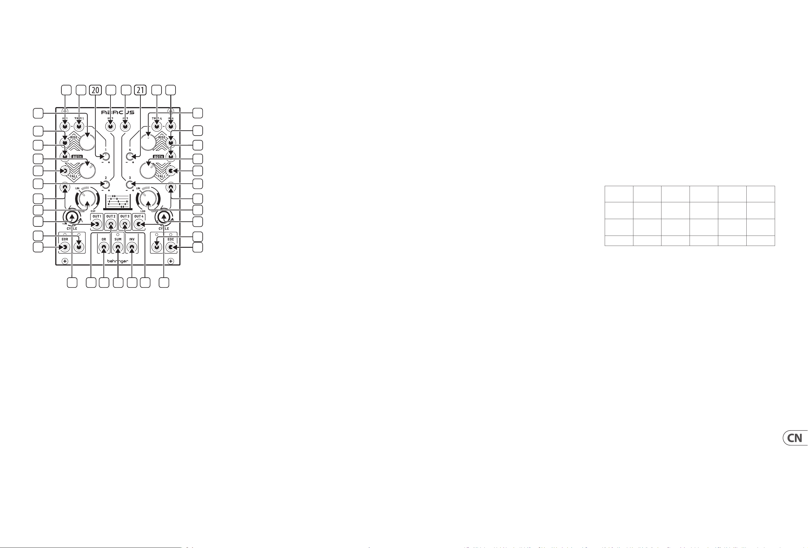
36 ABACUS Quick Start Guide 37
ABACUS 控制
(CN)
控制
1. CHANNEL 1 CV INPUT – 接受 +/- 10 伏范围内的可变电压, 用于通
道 1 处理。 如果没有电压, Abacus 将使用大约 +10 伏的自生成
电压。
2. CHANNEL 1 TRIGGER INPUT – 接受任何 +2.5 伏以上的 正向门或触发。
会激活 上升/下降功能。
3. CHANNEL 2 CV INPUT – 接受 +/- 10 伏范围内的 电压, 用于控制 20
的衰减 反相 (attenuverting)。
4. CHANNEL 3 CV INPUT – 接受 +/- 10 伏范围内的 电压, 用于控制 21
的衰减 反相 (attenuverting)。
5. CHANNEL 4 TRIGGER INPUT – 接受任何 +2.5 伏以上的 正向门或触
发。 会激活 上升/下降功能。
6. CHANNEL 4 CV INPUT – 接受 +/- 10 伏范围内的可变电压, 用于通
道 4 处理。 如果没有电压, Abacus 将使用大约 +10 伏的自生成
电压。
7. CHANNEL 1 RISE CV INPUT – 允许与控制 8 一起对上升功能进行
电压控制。 接受 +/- 8 V 范围内的电压。 正电压增加上升时间,
直至达到最大值; 负 电 压 减 少上 升 时间, 直至达到最小值。
8. CHANNEL 1 RISE TIME – 使用此控制设置上升时间。 请参阅下表
了解不同设置下的最长时间。 可通过将控制电压馈入插座 7
来进一步调制。
9. CHANNEL 4 RISE TIME – 使用此控制设置上升时间。 请参 阅下表
了解不同设置下的最长时间。 可通过将控制电压馈入插座 10
来进一步调制。
10. CHANNEL 4 RISE CV INPUT – 允许与控制 9 一起对上升功能进行
电压控制。 接受 +/- 8 V 范围内的电压。 正电压增加上升时间,
直至达到最大值; 负 电 压 减 少上 升 时间, 直至达到最小值。
11. CHANNEL 1 BOTH CV INPUT – 接受 +/- 8 伏范围内的电压。 正电压
将以指数形式减少总上升/下降时间, 直至达到最小值; 负电压
将增加直至达到最大值。
12. CHANNEL 2 ATTENUVERTER –使用此控制衰减 (顺时针) 或反相
(逆时针) 馈送到插座 3 上的通道 2 输入电压或内部产生的电
压, 范围 -10 伏至 +10 伏。
13. CHANNEL 3 ATTENUVERTER – 使用此控制衰减 (顺时针) 或反相
(逆时针) 馈送到插座 4 上的通道 3 输入电压或内部产生的电
压, 范围 -5 伏至 +6 伏。
14. CHANNEL 4 BOTH CV INPUT – 接受 +/- 8 伏范围内的电压。 正电压
将以指数形式减少总上升/下降时间, 直至达到最小值; 负电压
将增加直至达到最大值。
15. CHANNEL 1 FALL CV INPUT – 允许与控制 16 一 起对下降功能进行
电压控制。 接受 +/- 8 V 范围内的电压。 正电压增加下降时间,
直至达到最大值; 负电压减少下降 时间, 直至达到最小值。
16. CHANNEL 1 FALL TIME – 使用此控制设置下降时间。 请参 阅下表
了解不同设置下的最长时间。 可通过将控制电压馈入插座 15
来进一步调制。
17. CHANNEL 4 FALL TIME – 使用此控制设置下降时间。 请参 阅下表
了解不同设置下的最长时间。 可通过将控制电压馈入插座 18
来进一步调制。
18. CHANNEL 4 FALL CV INPUT – 允许与控制 17 一 起对下降功能进行
电压控制。 接受 +/- 8 V 范围内的电压。 正电压增加下降时间,
直至达到最大值; 负电压减少下降 时间, 直至达到最小值。
19. CHANNEL 1 CYCLE TRIGGER – 允许 +2.5 伏或以上的外部正向门或
触发器触发通道 1 的循环功能。
20. CHANNEL 1 ATTENUVERTER – 使用此控制在上升/下降处理后衰
减 (顺时针) 或反相 (逆时针)通道 1 的输出。 除非进行处理,
否则不会 通过内部电压。
21. CHANNEL 4 ATTENUVERTER – 使用此控制在上升/下降处理后衰
减 (顺时针) 或反相 (逆时针) 通道 4 的输出。 除非进行处理,
否则不会 通过内部电压。
22. CHANNEL 4 CYCLE TRIGGER – 允许 +2.5 伏或以上的外部正向门或
触发器触发通道 4 的循环功能。
23. CHANNEL 1 RESPONSE – 使用此控制可以改变通道 1 的 响应,
从对数到线性到 指数。 请参阅下面的表。
24. CHANNEL 4 RESPONSE – 使用此控制可以改变通道 4 的 响应,
从对数到线性到 指数。 请参阅下面的表。
25. CHANNEL 1 CYCLE – 使用此按钮启动通道 1 循环; 上升和下降将
开始循环, 直到再次按下按钮停止循环。 该按钮在循环时亮起。
当通过插座 19 外部触发循环时, 按钮会闪烁。 内部循环优先于
外部触发器。
26. CHANNEL 1 OUTPUT – 输出通道 1 经过处理的电压。
27. CHANNEL 2 OUTPUT – 输出通道 2 经过处理的电压。
28. CHANNEL 3 OUTPUT – 输出通道 3 经过处理的电压。
29. CHANNEL 4 OUTPUT – 输出通道 4 经过处理的电压。
30. CHANNEL 4 CYCLE – 使用此按钮启动通道 4 循环; 上升和下降将
开始循环, 直到再次按下按钮停止循环。 该按 钮在循环时亮
起。 当通过 插座 22 外部触发循环时, 按钮会闪烁。 内部循坏优
先于外部触发器。
31. CHANNEL 1 END OF RISE OUTPUT – 在上升函数顶部输出 +9 伏电
压, 关联的指示灯会做出只是, 该电压持续激活直到下 降周期
结束。
32. CHANNEL 1 UNITY OUTPUT – 当通道 1 循环时, 跟随 上升/下降功
能输出 0 - +10 伏电压;否则跟随通道输入, 不受衰减反相器影
响。 指示灯绿色表示正电压, 红色表示负电压。
33. OR OUTPUT – 根据通道 1–4 的衰减反相器设置 (控制器 12、 13、
20、 21) 输出模拟的或函数结果。 通道 1 和 4 需要包含外部电压。
34. SUM OUTPUT – 根据通道 1–4 的衰减反相器设置 (控制器 12、 13、
20、 21) 输出 +/- 10 伏范围内的总和电压。 指示灯绿色表示正电
压, 红色表示负电压。 通道 1 和 4 需要包含外部电压。
35. INVERTED SUM OUTPUT – 输出求和输出 34 的反相。
36. CHANNEL 4 UNITY OUTPUT – 当通道 4 循环时, 跟随 上升/下降功
能输出 0 - +10 伏电压; 否则跟随通道输入, 不受衰减反相器影
响。 指示灯绿色表示正电压, 红色表示负电压。
37. CHANNEL 4 END OF CYCLE OUTPUT – 在上升/下降循环结束时输出
一个 +9 伏电压, 由相关指示灯指示。
最大函数时间–通道 1– 通道 4
控制和衰减反相器设置为最大值(顺时针拧到底)
上升
时间
上升
最高
下降
时间
下降
最低
循环
时间
对数
9 分
0 秒
9.48 伏
25 分
15 秒
0.03 伏
42 分
45 秒
线性
55 秒 9.48 伏 50 秒 0.03 伏
1 分
45 秒
指数
7 秒 4.5 伏 5 秒 0.03 伏 10 秒
提示和技巧
• 通道 1 和 4 可用于调制彼此的上升、 下降或两种函数。
• 通道 4 的循环结束触发器可用于触发外部采样保持发生器,
然后可用作调制源。
• 通道 1 的上升结束输出可用作通道 1 和 4 上任何控制电压输
入的修饰器; 或作为外部电压输入到任何通道。
• 通道 2 和 3 可用于为通道 1 和 4 的控制电压输入提供偏置电压。
• 尝试将反相求和电压作为控制源。
1
2
3
4
5 6
8
9
10
11
7
12
19
23
25
32
26 27 33 34 35 28 29
37
36
30
24
22
31
16
15
13
14
17
18
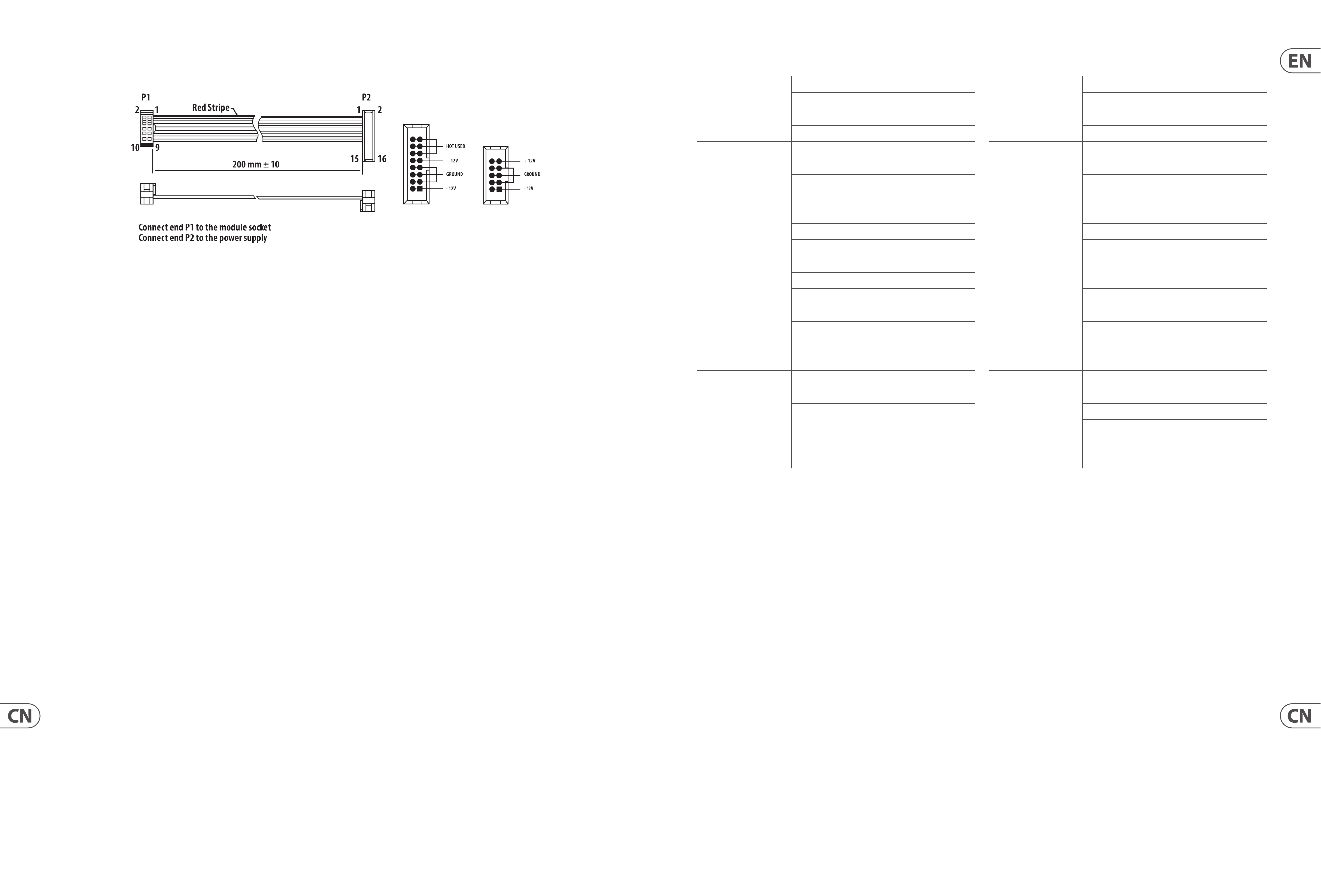
38 ABACUS Quick Start Guide 39
该模块配备了连接到标准 Eurorack 电源系统所需的电源线。 按照
这些步骤将模块连接到您的 Eurorack案例。
1. 关闭电源或机架外壳电源并断开电源电缆。
2. 将电源线上的 16 针连接器插入电源或机架盒上的插座中。
连接器有一个选项卡, 该选项卡将与插座中的间隙对齐, 因此不
能错误地插入该选项卡。 如果电源没有钥匙插座, 请务必将引脚
1 (-12 V) 定向到电缆上的红色条纹上。
3. 将 10 针连接器插入模块背面的插座中。 连接器有一个选项卡,
该选项卡将与插座对齐以获得正确的方向。
4. 电源线的两端牢固连接后, 您可以在情况下安装模块并打开 电源。
安装
必要的螺丝包含在用于安装在欧洲拉克箱中的模块中。 安装前连
接电源线。
根据机架外壳的不同, 可能会有一系列固定孔, 沿着机箱的长度间
隔 2 HP, 或允许单个螺纹板沿外壳长度滑动的轨道。 自由移动的螺
纹板允许模块的精确定位, 但在连接螺丝之前, 每个板应定位在
与模块安装孔的大致关系中。
将模块与 Eurorack 导轨对立, 以便每个安装孔与螺纹导轨或螺纹
板 对齐。 将螺丝部分连接以开始, 这将允许在调整它们时对定位
进行 小调整。 确定最终位置后, 拧紧螺丝。
电源连接
Specications
Inputs
CV 1-4, Trig 1-4, Rise 1 & 4, Fall 1 & 4
Both 1 & 4, Cycle 1 & 4: 3.5 mm jack
Outputs
CV 1-4, OR, SUM, INV, ƒ1 & 4, 1 EOR, 4 EOC
3.5 mm jack
Controls
1 & 4 Rise, 1 & 4 Fall, 1 & 4 Response knobs
1 - 4 attenuverter knobs
1 & 4 Cycle buttons
Impendances
Rise & Both CVs: 100 kΩ
Fall CVs: 33 kΩ
CV Inputs 1 & 4: 33 kΩ
CV Inputs 2 & 3: 75 kΩ
Trigger Inputs: 100 kΩ
Cycle Trigger Inputs: 50 kΩ
Outputs 1-4, INV, SUM, OR: 680 Ω
EOR/EOC: 2.2 kΩ
ƒ 1 & 4: 100 Ω
Sensitivities
Trigger 1 & 4: 4 V minimum
Cycle 1 & 4: 1.8 V minimum
Power Consumption 60 mA +12 V / 50 mA -12 V
Dimensions
20 hp
10 cm x 12.8 cm x 2.4 cm
(3.94 " x 5.04 " x 0.94 ")
Weight 191 g (6.74 oz)
Packaged Weight 284 g (10.02 oz)
技术参数
输入
CV 1-4, Trig 1-4, 上升 1 和 4, 下降 1 和 4
1 和 4 共用, 1 和 4 循环: 3.5 mm 插孔
输出
CV 1-4, OR, SUM, INV, ƒ1 和 4, 1 EOR, 4 EOC
3.5 mm 插孔
控制
1 和 4 上升, 1 和 4 下降, 1 和 4 响应旋钮
1 - 4 衰减旋钮
1 和 4 循环按钮
阻抗
上升和共用 CV: 100 kΩ
下降 CV: 33 kΩ
CV 输入 1 和 4: 33 kΩ
CV 输入 2 和 3: 75 kΩ
触发输入: 100 kΩ
循环触发输入: 50 kΩ
输出 1-4, INV, SUM, OR: 680 Ω
EOR/EOC: 2.2 kΩ
ƒ 1 和 4: 100 Ω
灵敏度
触发 1 和 4: 最小 4 V特
循环 1 和 4: 最小 1.8 V 特
功耗
60 mA +12 V / 50 mA -12 V
尺寸
20 hp
10 cm x 12.8 cm x 2.4 cm
(3.94 " x 5.04 " x 0.94 ")
重量
191 g (6.74 oz)
包装重量
284 g (10.02 oz)

40 ABACUS Quick Start Guide 41
FEDERAL COMMUNICATIONS
COMMISSION COMPLIANCE
INFORMATION
Responsible Party Name: Music Tribe Commercial NV Inc.
Address: 122 E. 42nd St.1,
8th Floor NY, NY 10168,
United States
Email Address: legal@musictribe.com
This equipment has been tested and found to comply with the limits for a Class B
digital device, pursuant to part 15 of the FCC Rules. These limits are designed
to provide reasonable protection against harmful interference in a residential
installation. This equipment generates, uses and can radiate radio frequency
energy and, if not installed and used in accordance with the instructions, may cause
harmful interference to radio communications. However, there is no guarantee that
interference will not occur in a particular installation. If this equipment does cause
harmful interference to radio or television reception, which can be determined
by turning the equipment o and on, the user is encouraged to try to correct the
interference by one or more of the following measures:
• • Reorient or relocate the receiving antenna.
• • Increase the separation between the equipment and receiver.
• • Connect the equipment into an outlet on a circuit dierent from that to which the
receiver is connected.
• • Consult the dealer or an experienced radio/TV technician for help.
This equipment complies with Part 15 of the FCC rules. Operation is subject to the
following two conditions:
(1) this device may not cause harmful interference, and
(2) this device must accept any interference received, including interference that may
cause undesired operation.
Important information:
Changes or modications to the equipment not expressly approved by Music Tribe
can void the user’s authority to use the equipment.
Hereby, Music Tribe declares that this product is in compliance with General Product
Safety Regulation (EU) 2023/988, Directive 2014/30/EU, Directive 2011/65/EU and
Amendment 2015/863/EU, Directive 2012/19/EU, Regulation 519/2012 REACH SVHC
and Directive 1907/2006/EC.
Full text of EU DoC is available at https://community.musictribe.com/
EU Representative: Music Tribe Brands DK A/S
Address: Gammel Strand 44, DK-1202 København K, Denmark
UK Representative: Music Tribe Brands UK Ltd.
Address: 8
th
Floor, 20 Farringdon Street London EC4A 4AB, United Kingdom
Correct disposal of this product: This symbol indicates that this
product must not be disposed of with household waste,
according to the WEEE Directive (2012/19/EU) and your
national law. This product should be taken to a collection
center licensed for the recycling of waste electrical and
electronic equipment (EEE). The mishandling of this type of
waste could have a possible negative impact on the
environment and human health due to potentially hazardous
substances that are generally associated with EEE. At the same
time, your cooperation in the correct disposal of this product will contribute to the
ecient use of natural resources. For more information about where you can take
your waste equipment for recycling, please contact your local city oce, or your
household waste collection service.
型号: ABACUS
合成器与采样器
制造商: Empower Tribe Commercial FZE
Made in China 中国制造
CAN ICES–003 (B)/NMB–003 (B)
Behringer
ABACUS
ABACUS

We Hear You