User Manual
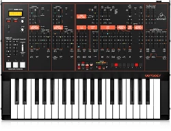
MODEL D
Authentic Analog Synthesizer with 3 VCOs, Ladder Filter, LFO and Eurorack Format
V 1.0

2 MODEL D User Manual
Thank you
Thank you very much for expressing your condence in Behringer products by
purchasing the MODEL D analog synthesizer - with 3 VCOs, Classic Ladder Filter,
LFO, 16-Voice Poly Chain and Eurorack Format
Table of Contents
Thank you .......................................................................2
Important Safety Instructions ...................................... 3
Legal Disclaimer ............................................................. 3
Limited warranty ............................................................ 3
About the MODEL D ....................................................... 4
1. Introduction ............................................................... 5
2. Features ...................................................................... 5
3. Controls ...................................................................... 7
4. Overview .................................................................. 12
5. Calibration................................................................ 14
6. Hook-up examples ..................................................26
7. System Exclusive Commands ..................................30
8. Eurorack Installation ............................................... 32
9. Specications ...........................................................34
10. Glossary .................................................................. 36
3 MODEL D User Manual
Important Safety
Instructions
LEGAL DISCLAIMER
LIMITED WARRANTY
Terminals marked with this symbol carry
electrical current of sucient magnitude
to constitute risk of electric shock.
Use only high-quality professional speaker cables with
¼" TS or twist-locking plugs pre-installed. Allother
installation or modication should be performed only
by qualiedpersonnel.
This symbol, wherever it appears,
alertsyou to the presence of uninsulated
dangerous voltage inside the
enclosure-voltage that may be sucient to constitute a
risk ofshock.
This symbol, wherever it appears,
alertsyou to important operating and
maintenance instructions in the
accompanying literature. Please read the manual.
Caution
To reduce the risk of electric shock, donot
remove the top cover (or the rear section).
No user serviceable parts inside. Refer servicing to
qualied personnel.
Caution
To reduce the risk of re or electric shock,
do not expose this appliance to rain and
moisture. The apparatus shall not be exposed to dripping
or splashing liquids and no objects lled with liquids,
suchas vases, shall be placed on the apparatus.
Caution
These service instructions are for use
by qualied service personnel only.
Toreduce the risk of electric shock do not perform any
servicing other than that contained in the operation
instructions. Repairs have to be performed by qualied
servicepersonnel.
1. Read these instructions.
2. Keep these instructions.
3. Heed all warnings.
4. Follow all instructions.
5. Do not use this apparatus near water.
6. Clean only with dry cloth.
7. Do not block any ventilation openings. Install in
accordance with the manufacturer’s instructions.
8. Do not install near any heat sources such as
radiators, heat registers, stoves, or other apparatus
(including ampliers) that produce heat.
9. Do not defeat the safety purpose of the polarized
or grounding-type plug. A polarized plug has two blades
with one wider than the other. A grounding-type plug
has two blades and a third grounding prong. The wide
blade or the third prong are provided for your safety. Ifthe
provided plug does not t into your outlet, consult an
electrician for replacement of the obsolete outlet.
10. Protect the power cord from being walked on or
pinched particularly at plugs, convenience receptacles,
and the point where they exit from the apparatus.
11. Use only attachments/accessories specied by
themanufacturer.
12. Use only with the
cart, stand, tripod, bracket,
or table specied by the
manufacturer, orsold with
the apparatus. When a cart
is used, use caution when
moving the cart/apparatus
combination to avoid
injury from tip-over.
13. Unplug this apparatus during lightning storms or
when unused for long periods of time.
14. Refer all servicing to qualied service personnel.
Servicing is required when the apparatus has been
damaged in any way, such as power supply cord or plug
is damaged, liquid has been spilled or objects have fallen
into the apparatus, the apparatus has been exposed
to rain or moisture, does not operate normally, or has
beendropped.
15. The apparatus shall be connected to a MAINS socket
outlet with a protective earthing connection.
16. Where the MAINS plug or an appliance coupler is
used as the disconnect device, the disconnect device shall
remain readily operable.
17. Correct disposal of this
product: This symbol indicates that
this product must not be disposed
of with household waste,
according to the WEEE Directive
(2012/19/EU) and your national
law. This product should be taken
to a collection center licensed for
the recycling of waste electrical and electronic equipment
(EEE). The mishandling of this type of waste could have a
possible negative impact on the environment and human
health due to potentially hazardous substances that are
generally associated with EEE. At the same time, your
cooperation in the correct disposal of this product will
contribute to the ecient use of natural resources.
For more information about where you can take your
waste equipment for recycling, please contact your local
city oce, or your household waste collection service.
18. Do not install in a conned space, such as a book
case or similar unit.
19. Do not place naked ame sources, such as lighted
candles, on the apparatus.
20. Please keep the environmental aspects of battery
disposal in mind. Batteries must be disposed-of at a
battery collection point.
21.
This apparatus may be used in tropical and moderate
climates up to 45°C.
Music Tribe accepts no liability for any loss which may
be suered by any person who relies either wholly or in
part upon any description, photograph, or statement
contained herein. Technical specications, appearances
and other information are subject to change without
notice. All trademarks are the property of their
respective owners. Midas, Klark Teknik, Lab Gruppen,
Lake, Tannoy, Turbosound, TC Electronic, TC Helicon,
Behringer, Bugera, Aston Microphones and Coolaudio
are trademarks or registered trademarks of Music
Tribe Global Brands Ltd. © Music Tribe Global Brands
Ltd. 2023 All rights reserved.
For the applicable warranty terms and conditions
and additional information regarding Music Tribe’s
Limited Warranty, please see complete details online at
community.musictribe.com/pages/support#warranty.

4 MODEL D User Manual
About the MODEL D
• • Legendary analog synthesizer with triple VCO design allows for insanely fat
music creation
• • Authentic reproduction of original “D Type” circuitry with matched
transistors and JFETs
• • Ultra-high precision 0.1% Thin Film resistors and Polyphenylene Sulphide
capacitors
• • Pure analog signal path based on authentic VCO, VCF and VCA designs
• • 5 variable oscillator shapes with variable pulse widths for ultimate sounds
• • Classic 24 dB ladder lter with resonance for legendary sound performance
• • Switchable low/high pass lter mode for enhanced sound creation
• • Dedicated and fully analog triangle/square wave LFO
• • 16-voice Poly Chain allows combining multiple synthesizers for up to 16 voice
polyphony
• • Semi-modular design requires no patching for immediate performance
• • Overdrive circuit adds insane spice and edge to your sounds
• • Noise generator dramatically expands waveform generation
• • Complete Eurorack solution –main module can be transferred to a standard
Eurorack case
• • 48 controls give you direct and real-time access to all important parameters
• • External audio input for processing external sound sources
• • Low and high level outputs featuring highest signal integrity signal stages
• • Comprehensive MIDI implementation with MIDI channel and Voice Priority
selection
• • 3-Year Warranty Program*
• • Designed and engineered in the U.K.
*Warranty details can be found at music-group.com.
5 MODEL D User Manual
1. Introduction
An ultra-aordable homage to an iconic synthesizer, with all the features of the
original and then some, the Behringer MODEL D lets you conjure up virtually any
monophonic sound imaginable with incredible nesse and ease.
The pure analog signal path is based on authentic VCO, VCF, VCA and ladder lter
designs in conjunction with a dedicated and fully analog triangle/ square wave
LFO. And when it comes to protection and convenience, the MODEL D can even be
mounted in a standard Eurorack, making it ideal for the studio and/or the road.
Owning a MODEL D is like having your own personal time machine, enabling you
to freely embrace the past – or shape the future!
Please read the manual carefully and keep it for future reference.
1.1 Before you get started
1.1.1 Shipment
The MODEL D was carefully packed in the factory to guarantee safe transport.
Nevertheless, we recommend that you carefully examine the packaging and
its contents for any signs of physical damage, which may have occurred during
transit.
If the unit is damaged, please do NOT return it to us, but notify
your dealer and the shipping company im mediately, otherwise
claims for damage or replacement may not be granted.
1.1.2 Initial operation
Be sure that there is enough space around the unit for cooling purposes and,
to avoid over-heating, please do not place the MODEL D on high-temperature
devices such as radiators or power amps.
WARNING: The MODEL D is supplied with a AC power adapter.
It meets the required safety standards. Do not use any other
power adapter.
WARNING: Please make sure that all units have a proper ground
connection. Foryour own safety, never remove or disable the
ground conductor from any units or AC power cords in your
system.
1.2 The product manual
This product manual is designed to give you both an overview of the MODEL D
analog synthesizer, as well as detailed information on each of the controls and
parameters. You will nd an overview of the physical control elements in the
next chapter.
1.3 Preparation
CAUTION: Remember to turn your monitors / loudspeakers on
last when powering up your system, and turn your monitors /
loudspeakers o rst when powering down your system.
2. Features
True to the Original
Great care has been taken in designing the MODEL D including the true to the
original “D Type” circuitry with its matched transistors and JFETs, ultra-high
precision 0.1% thin lm resistors and polyphenylene sulphide capacitors. This
highly-focused attention to detail is what gives the MODEL D its ultra-exible
sound shaping capability, which covers everything from super-fat bass and lead
tones, stunning eects, progressive organ sounds – and all the way out to the
otherworldly sounds of your imagination.
Big, Fat Tones
The inspired synthesizer tracks laid down in the 1970s and '80s are etched in the
annals of progressive rock, wave and synth-pop music forever, making them
truly classic in every sense of the word. MODEL D’s pure analog signal path with
legendary VCO, VCF and VCA circuits, lets you recreate all of that magic – or
design incredibly fat and original sounds that will make you a legend in your own
right!
VCO Triple Play
MODEL D’s 3 highly-exible Voltage Controlled Oscillators (VCOs) provide an
incredible range of 5 waveforms for sculpting the perfect sound. Oscillators 1 and
2 options include: triangular; triangular/saw; saw; square; wide pulse; and narrow
pulse, while OSC 3 features: triangular; reverse saw; saw; square; wide pulse; and
narrow pulse. Additionally, all 3 VCOs can be adjusted across an extremely-wide,
6-octave range (LO, 32', 16', 8', 4', and 2'). This amazing exibility gives you all the
tools you need to be your creative best.
24 dB Ladder Filter and VCA
The very heart of MODEL D’s sound is its highly-exible 24 dB Ladder Filter, which
lets you freely experiment with the Cuto Frequency, Emphasis, and Contour to
dial in the perfect sound.
MODEL D’s Filter Mode switch can be set to either Lo- or Hi-pass for selecting the
range of your choice. You can also adjust the Attack, Decay, and Sustain controls
to aect the cuto frequency with time. The VCA Decay switch lets you set the
length of time the note lingers after the key has been released. Additionally,
support for lter-keytracking allows you to select how much ltering is applied
based on the note being played. And if you want to add modulation, just set the
Filter Modulation switch to the On position and use the Controllers Mod Mix knob
to make it so. The VCA can even be overloaded via MODEL D’s feedback circuit to
add insane spice and edge to your sounds – without saying "goodbye" to your
precious low-end content.
Making Waves
You are always in complete control of MODEL D’s onboard modulators, which
feature: adjustable Tune; Mod Depth; LFO Rate; Glide (portamento); and Mod Mix
knobs. A range of switches is provided for selecting between: triangle or square
wave oscillation; modulation On or O; OSC 3 or Filter EG (Filter Envelope); and
Noise (Mod SRC) or LFO. The Tune knob is used to adjust the frequency of OSC 1,
2 and 3 (as long as the OSC 3 switch is turned o). The internal Noise generator,
which is switchable between either Pink or White noise for dramatically
expanded waveform generation, is the default modulation source, unless an
external Mod Source is connected at the 3.5 mm input jack. The Behringer MODEL
D is the ultimate mono, all-analog synthesizer in its class – especially when it
comes to sound quality, versatility and aordability.

6 MODEL D User Manual
16-Note Poly Chain Ready
While it is a monophonic instrument (one note at a time), MODEL D’s 16-note
Poly Chain function lets you combine multiple synthesizers for up to 16-voice
polyphony – plus it provides vastly improved reliability and stability over its
1970s and '80s predecessors.
Semi-Modular Design
Designed around an intuitively-linear workow, MODEL D benets greatly
from its semi-modular design, which requires no patching for immediate
performance. Just connect your favorite keyboard or computer via MIDI over DIN
or USB – and start exploring the world of analog music synthesis right out-of-
the-box.
Eurorack Ready
Designed to handle the rigors of life on the road or in the studio, your MODEL D
can easily be transferred into a standard Eurorack case for the perfect integration
into your existing system.
Controls and Connectivity
The MODEL D has 29 knobs and 19 switches, all laid out in a highly-intuitive
format that puts the joy back into your music creation.
Input and output connections include: MIDI I/O and Thru over USB/MIDI DIN;
modulation and audio inputs; OSC1 frequency control; external control of lter
cuto, resonance and contour; Main Out – and Phones, with its own dedicated
Volume control.
Unleash Your Imagination
When it comes to not just pushing envelopes but creating them, MODEL D
gives your imagination its voice – and it’s so very aordable. When modern
performance calls for classic analog sound – it calls for the Behringer MODEL D!
You Are Covered
We always strive to provide the best possible Customer Experience. Our products
are made in our own MUSIC Tribe factory using state-of-the-art automation,
enhanced production workows and quality assurance labs with the most
sophisticated test equipment available in the world. As a result, we have one of
the lowest product failure rates in the industry, and we condently back it up
with a generous Warranty program.
7 MODEL D User Manual
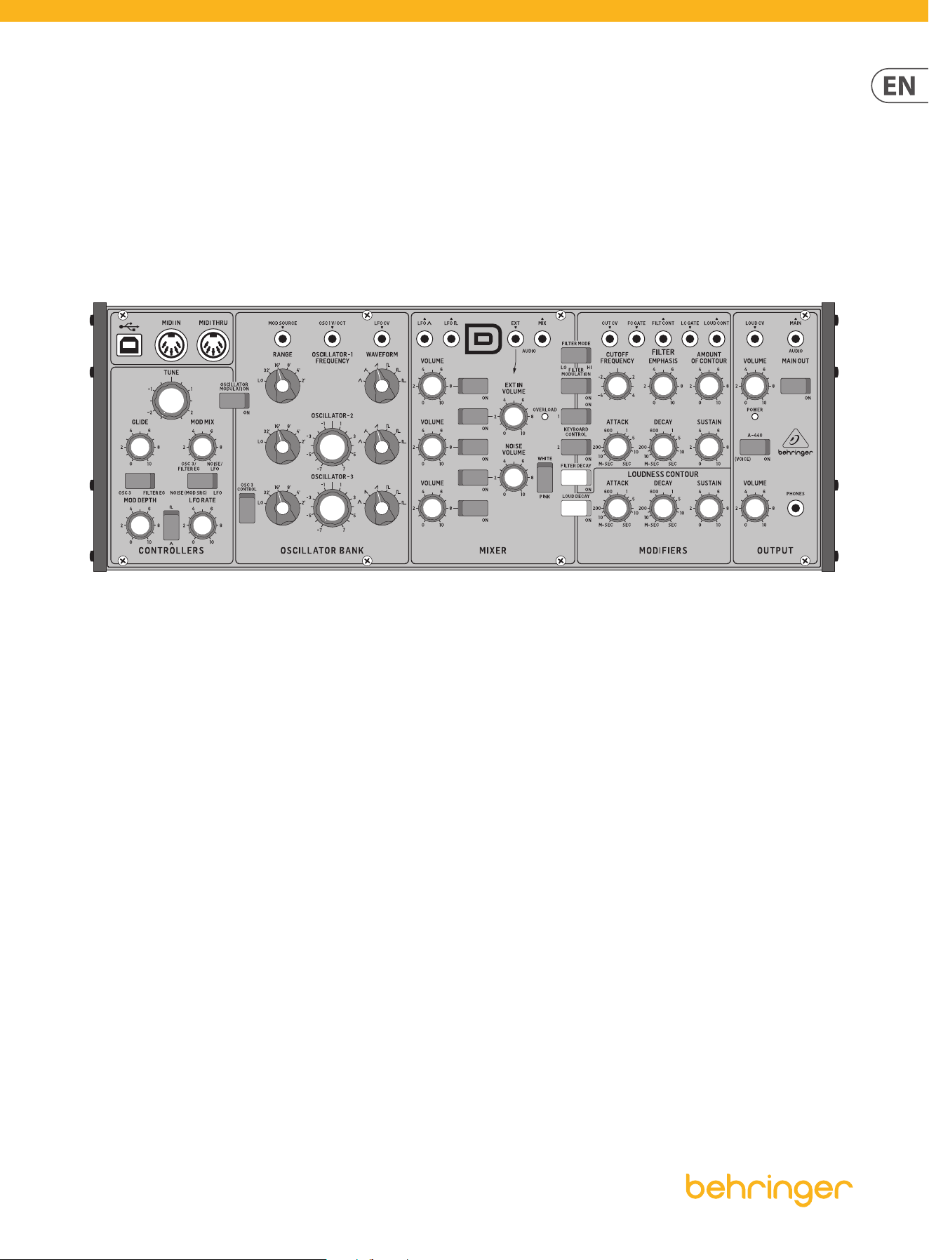
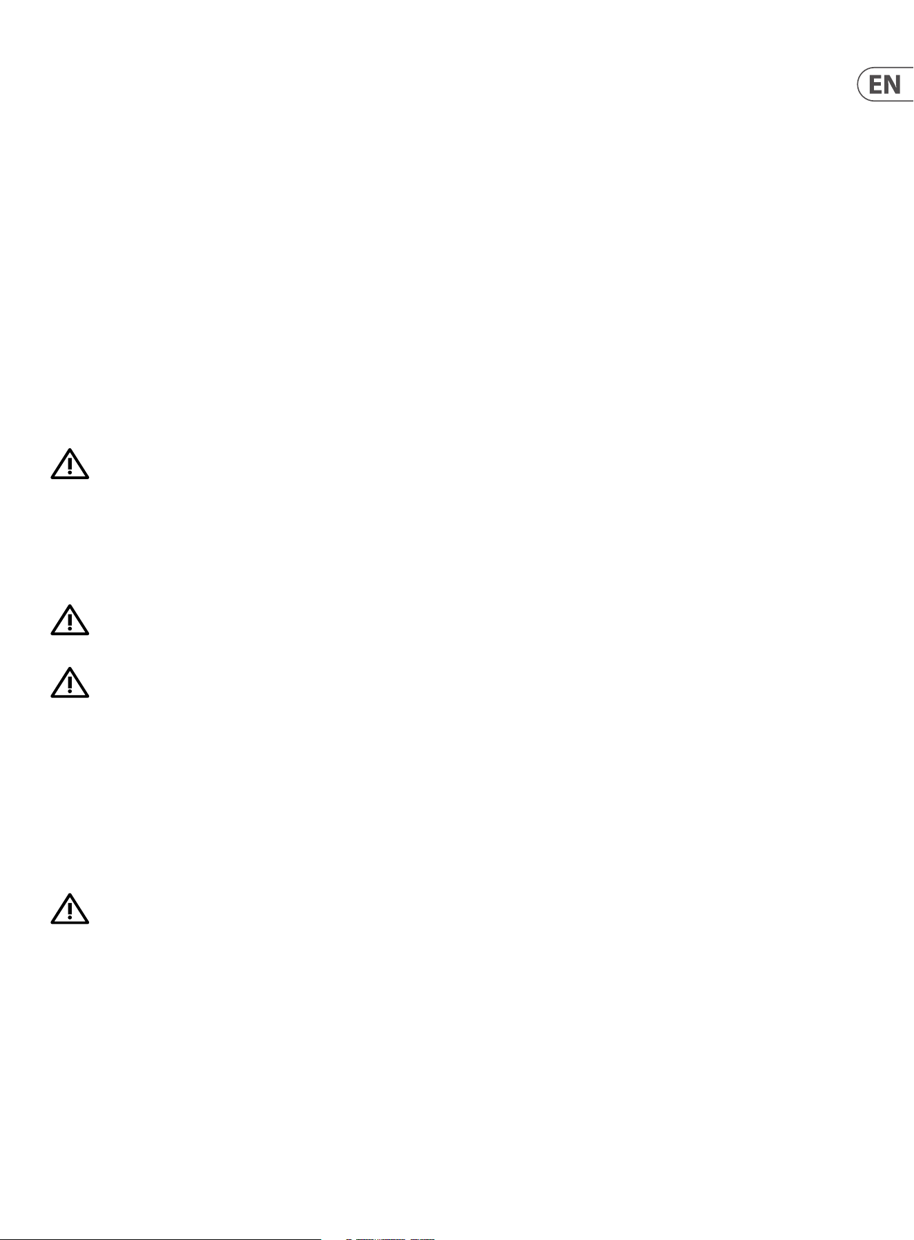
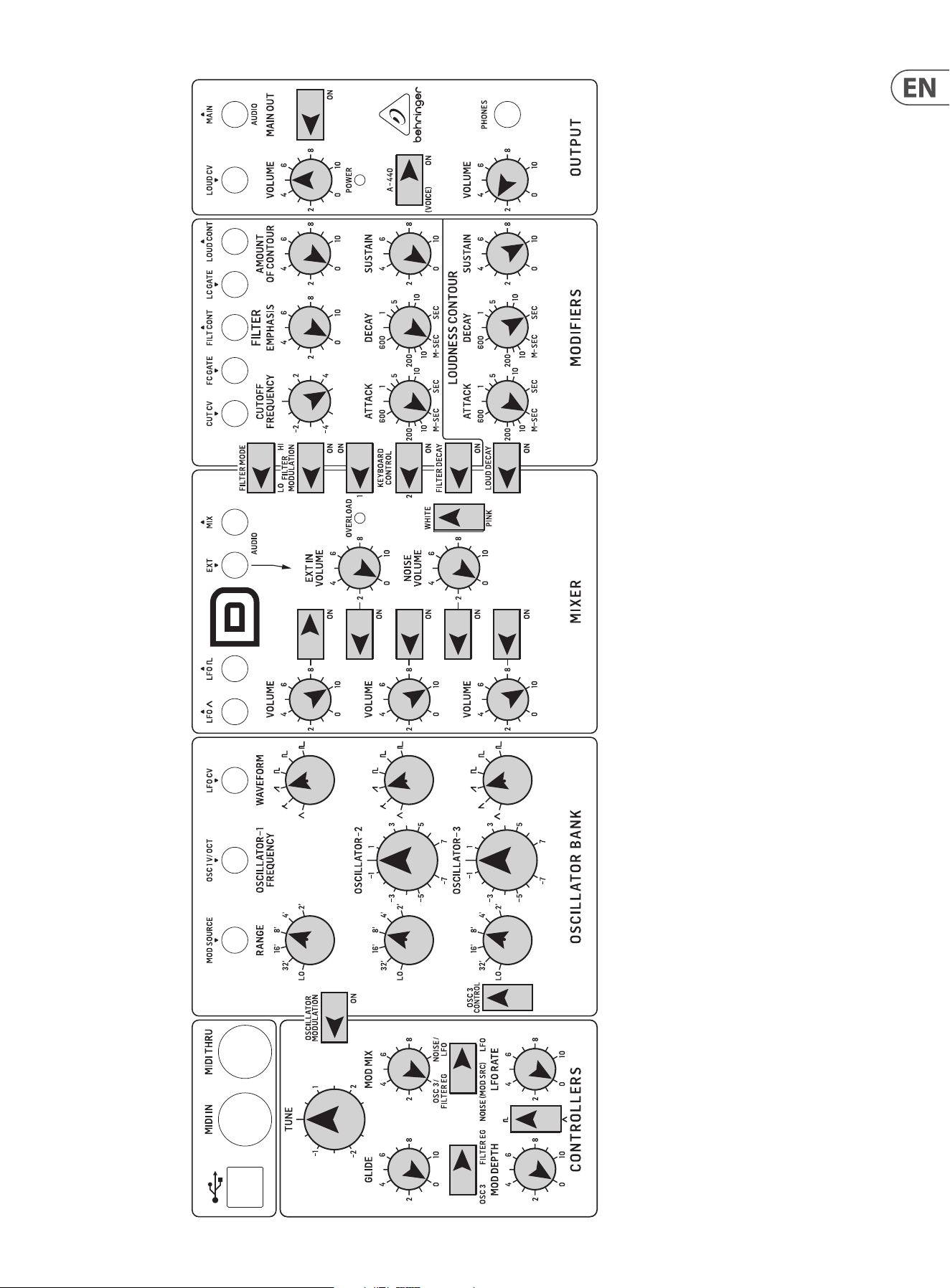
3. Controls
3.1 Top Controls
(1)
(6)
(7)
(36)
(47)
(46)
(35)
(34)
(8)
(9)
(5)
(33)
(32)
(44)
(42)
(45)
(43)
(31)
(30)
(4)
(2) (3) (17)
(10) (11) (12) (13) (14) (15) (16) (20) (21) (22)
(24)
(25)
(23)
(18) (26) (27)
(37) (38) (39) (40)
(41)
(48)
(49)
(28) (29)(19)
8 MODEL D User Manual
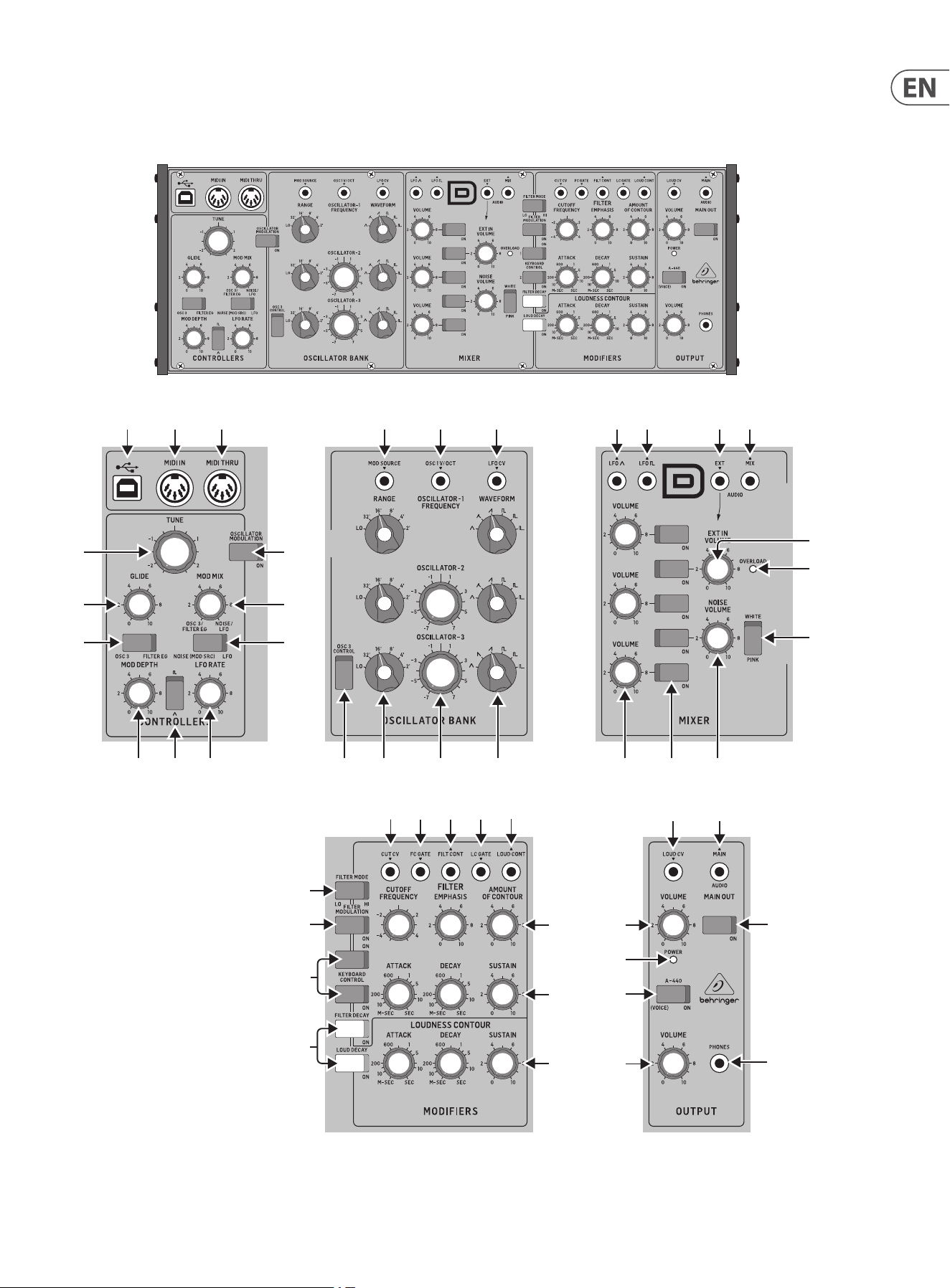
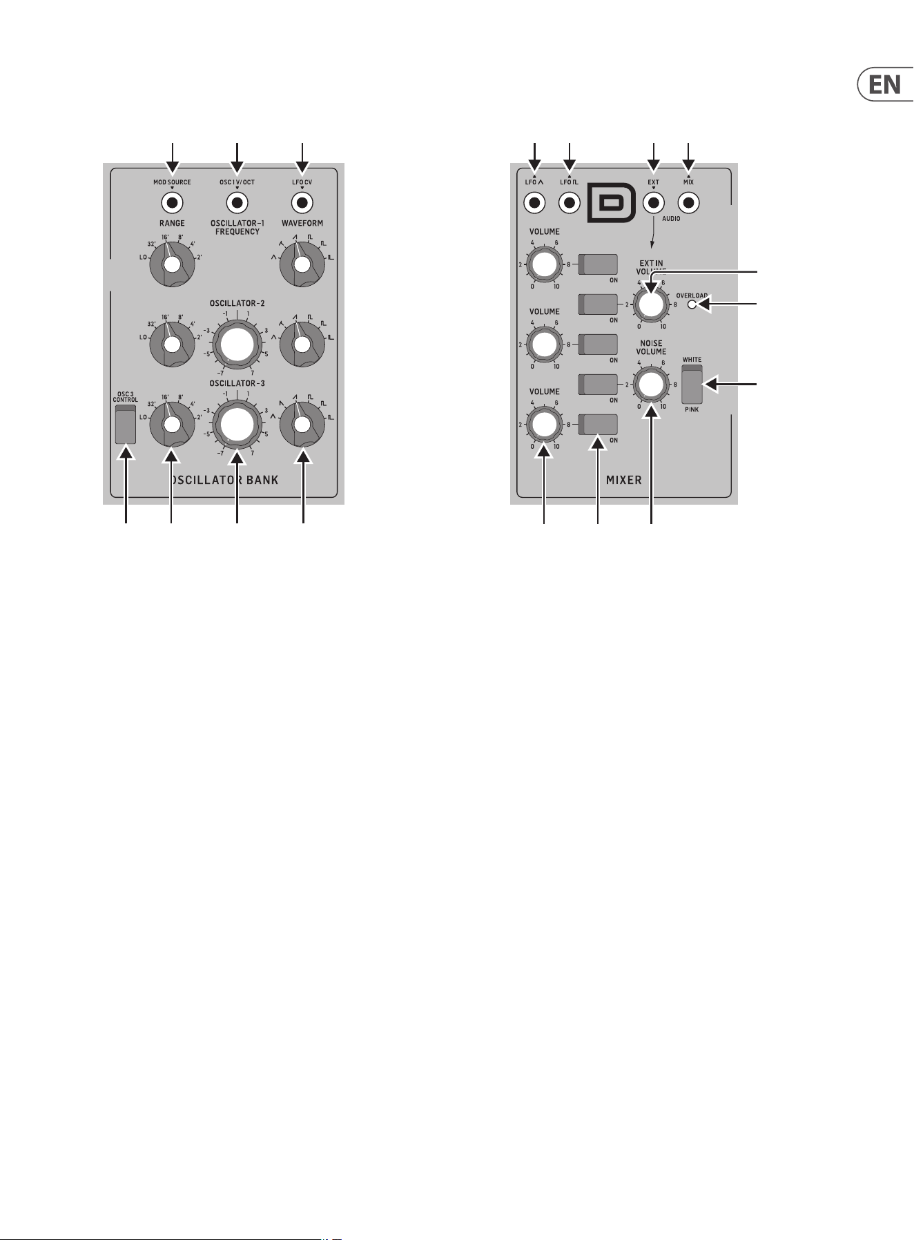
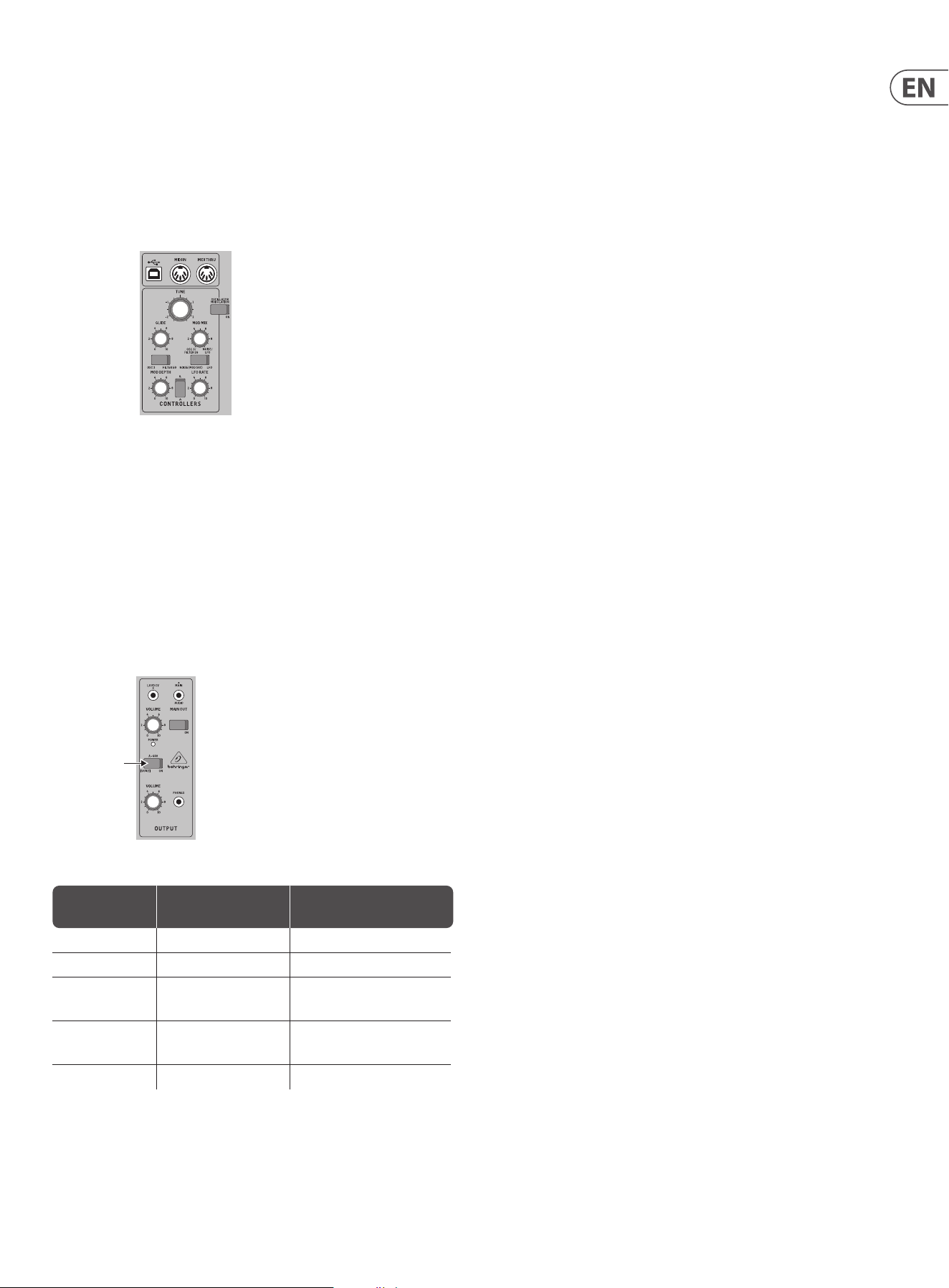
3.1.1 MIDI Section
(1) USB PORT - this USB type B jack allows connection to a computer. The
MODEL D will show up as a class-compliant USB MIDI device, capable of
supporting MIDI in and out.
USB MIDI IN - accepts incoming MIDI data from an application.
USB MIDI OUT - sends MIDI data to an application.
(2) MIDI IN - this 5-pin DIN jack receives MIDI data from an external source.
This will commonly be a MIDI keyboard, an external hardware sequencer,
a computer equipped with a MIDI interface, etc.
(3) MIDI THRU - this 5-pin DIN jack is used to pass through MIDI data
received at the MIDI INPUT. This will commonly be sent to another
MODEL D synthesizer to run a Poly Chain or to a drum machine assigned to
a dierent MIDI Channel.
(1)
(6)
(7)
(36)
(47)
(46)
(35)
(34)
(8)
(9)
(5)
(33)
(32)
(44)
(42)
(45)
(43)
(31)
(30)
(4)
(2) (3)
(17)
(10) (11) (12) (13) (14) (15) (16) (20) (21) (22)
(24)
(25)
(23)
(18) (26) (27)
(37) (38) (39) (40)
(41)
(48)
(49)
(28) (29)(19)
3.1.2 Controllers Section
(4) OSC3/FILTER EG - switch between OSC3 or the Filter Envelope as a
modulation source.
(5) GLIDE - adjust the amount of Glide (Portamento), between notes on the
keyboard.
(6) TUNE - adjust the frequency of oscillators 1, 2, and 3. (OSC3 is not aected
if the OSC3 CONTROL switch is o .)
(7) OSCILLATOR MODULATION - when ON, the three oscillators are
modulated by the modulation mix, set by the MOD MIX knob.
(8) MOD MIX - adjust the modulation mix between OSC3/Filter EG and Noise/
LFO.
(9) NOISE (MOD SRC)/ LFO - switch between Noise (or external modulation
source) or Low Frequency Oscillator (LFO) as a modulation source.
(10) MOD DEPTH - adjust the modulation depth from o to maximum. The
modulation depth can also be adjusted using the modulation wheel on a
MIDI keyboard.
(11) WAVE SHAPE - select the LFO wave shape from either triangular or square
wave.
(12) LFO RATE - adjusts the frequency of the LFO.
(1)
(6)
(7)
(36)
(47)
(46)
(35)
(34)
(8)
(9)
(5)
(33)
(32)
(44)
(42)
(45)
(43)
(31)
(30)
(4)
(2) (3) (17)
(10) (11) (12)
(13) (14) (15) (16) (20) (21) (22)
(24)
(25)
(23)
(18) (26) (27)
(37) (38) (39) (40)
(41)
(48)
(49)
(28) (29)(19)
9 MODEL D User Manual
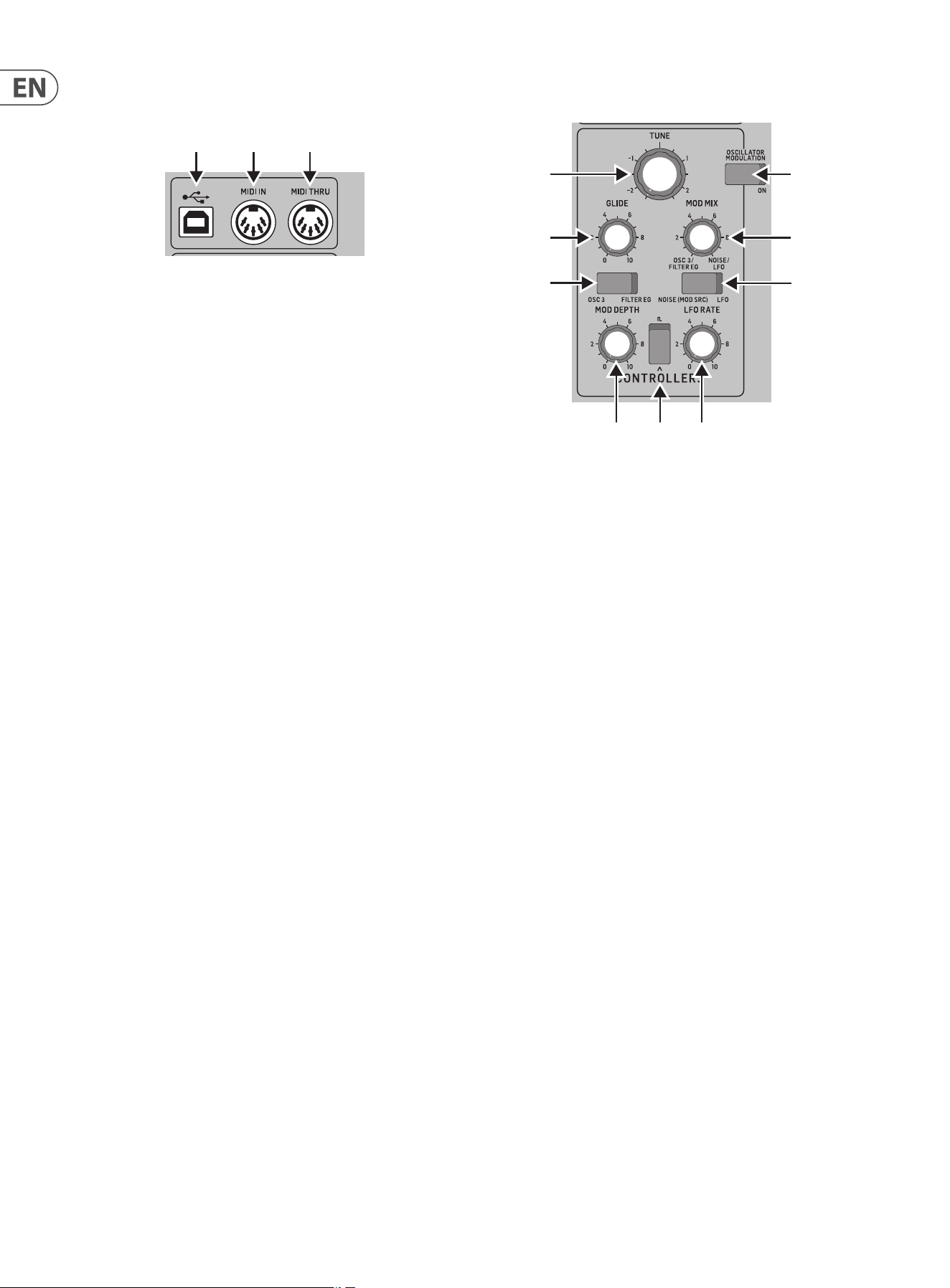
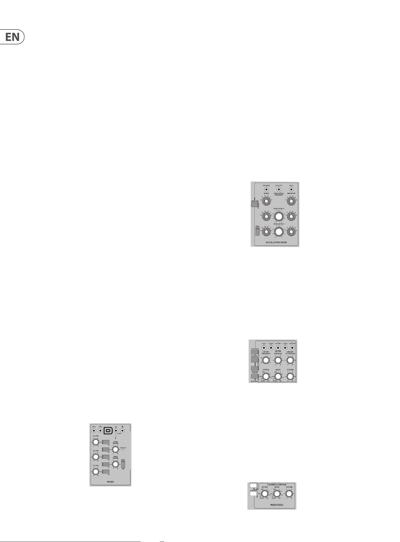
3.1.3 Oscillator Bank Section
(13) OSC 3 CONTROL - when ON, the frequency of OSC 3 will vary with the
keyboard. When OFF, the keyboard, Pitch wheel, and Modulation wheel,
will have no eect on OSC 3.
(14) FREQUENCY RANGE - select from six frequency ranges of Oscillator
1, 2, or 3.
(15) FREQUENCY ADJUSTMENT - adjust the frequency of Oscillator 2 or 3.
(16) WAVE SHAPE - select the wave shape of Oscillator 1, 2, or 3 from:
triangular, triangular/ sawtooth (OSC1 and 2), reverse sawtooth (OSC3),
sawtooth, square, medium pulse, and narrow pulse.
(17) MOD SOURCE (INPUT) - allows connection of an external modulation
source. If nothing is connected here, then the internal Noise generator is
available as a modulation source.
(18) OSC 1V/OCT (INPUT) - this input allows the frequency of the three
oscillators to be adjusted by an external control voltage (1 Volt input
increase, will increase the frequency by one Octave).
(19) LFO CV (INPUT) - allows control of the LFO frequency by an external
control voltage.
(1)
(6)
(7)
(36)
(47)
(46)
(35)
(34)
(8)
(9)
(5)
(33)
(32)
(44)
(42)
(45)
(43)
(31)
(30)
(4)
(2) (3)
(17)
(10) (11) (12)
(13) (14) (15) (16)
(20) (21) (22)
(24)
(25)
(23)
(18)
(26) (27)
(37) (38) (39) (40)
(41)
(48)
(49)
(28) (29)
(19)
3.1.4 Mixer Section
(20) VOLUME - adjust the volume of Oscillator 1, 2, or 3.
(21) ON/OFF - select the sources to play from OSC1, OSC2, OSC3, Noise, and
External Input, or any combination of these 5 sources.
(22) NOISE VOLUME - adjust the level of the internal Noise source.
(23) WHITE/PINK - switch the internal Noise source from Pink noise to White
noise.
(24) OVERLOAD - indicates when the audio levels of the mix are overloading
the mixer section.
(25) EXT IN VOLUME - adjust the level of any external source playing into the
external Input.
If nothing is connected to the external input, then instead of any external
audio coming in at this point, the main MODEL D output is automatically
connected here. This creates a feedback path from the output back into
the mixer section, to get extra phat bass or extra crunch. In this case,
the EXT IN volume control will adjust the level of the incoming main audio
fed back into the mixer section.
(26) LFO Triangular (OUTPUT) - outputs the internal LFO triangular-
wave signal.
(27) LFO Square (OUTPUT) - outputs the internal LFO square-wave signal.
(28) EXT (INPUT) - connect any external line-level audio source to this
3.5 mm input. If nothing is connected here, then the main audio output is
internally connected to this external input.
(29) MIX (OUTPUT) - outputs the nal mix from this Mixer section.
(1)
(6)
(7)
(36)
(47)
(46)
(35)
(34)
(8)
(9)
(5)
(33)
(32)
(44)
(42)
(45)
(43)
(31)
(30)
(4)
(2) (3) (17)
(10) (11) (12) (13) (14) (15) (16)
(20) (21) (22)
(24)
(25)
(23)
(18)
(26) (27)
(37) (38) (39) (40)
(41)
(48)
(49)
(28) (29)
(19)
10 MODEL D User Manual
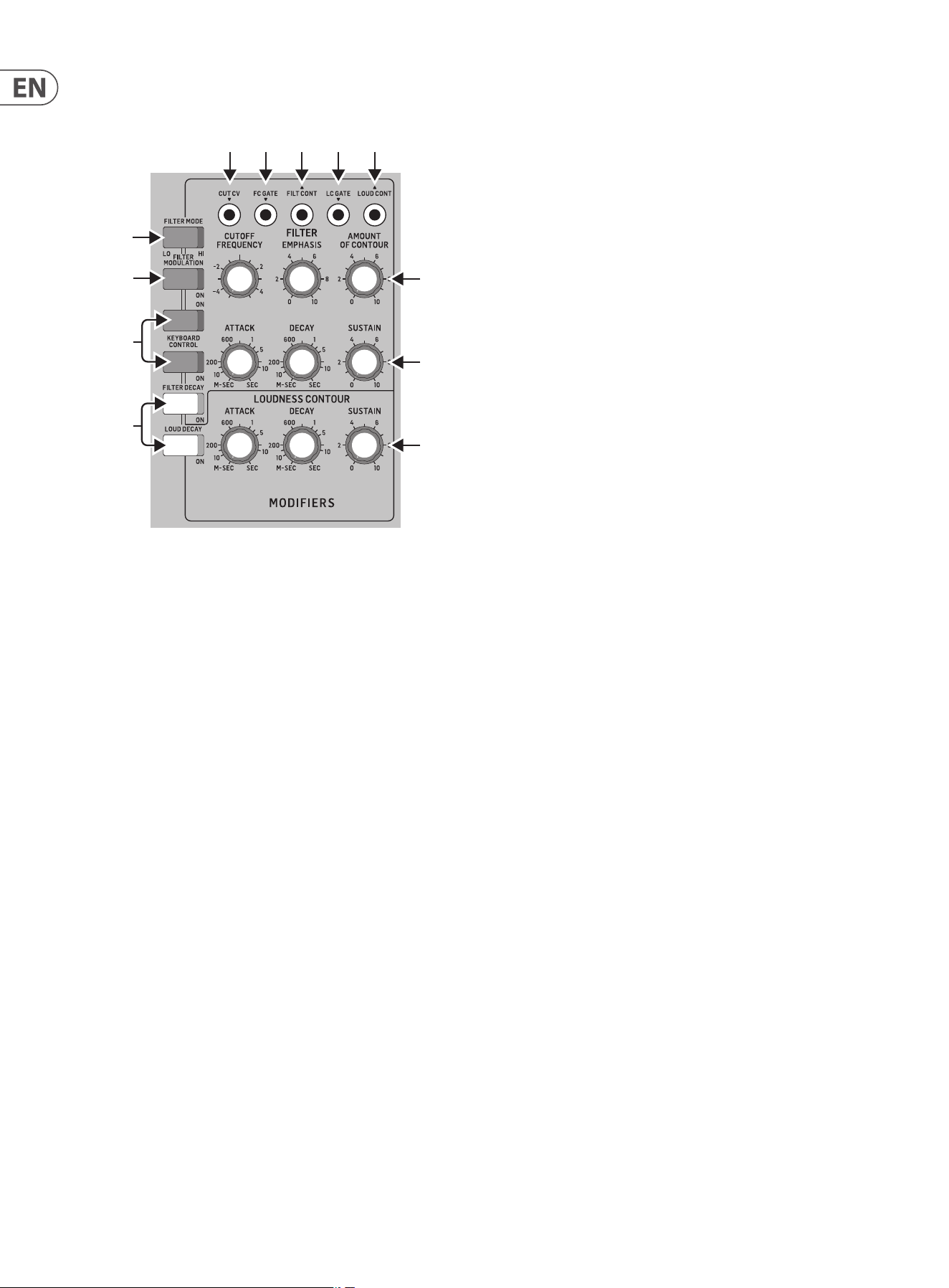
3.1.5 Modiers Section
(30) DECAY - when ON, the signal will decay during the time set by the DECAY
TIME knob after a note or external trigger is released. When OFF, it will
decay immediately after a note or external trigger is released.
LOUDNESS DECAY - aects the decay of volume level of the Loudness
section.
FILTER DECAY - aects the decay of the cuto frequency of the Filter
section.
(31) KEYBOARD CONTROL - these switches vary the eect of the keyboard
tracking, where the lter section is aected by the pitch of note played.
Switch 1 and 2 OFF - no keyboard tracking eect
Switch 1 and 2 ON - maximum eect
Switch 1 ON (only) - 1⁄3 of maximum eect
Switch 2 ON (only) - 2⁄3 of maximum eect
(32) FILTER MODULATION - when ON, the lter section is modulated by the
modulation mix, set by the MOD MIX knob.
(33) FILTER MODE - select the lter between Low-Pass or High-Pass.
(34) LOUDNESS CONTOUR - these 3 knobs adjust the overall shape enveloping
the audio after it has passed through the mixer section and lter section.
The controls aect the change in volume (loudness) level with time.
ATTACK - adjust the time it takes for the signal to reach a maximum
level after a note is played.
DECAY TIME - adjust the time for a signal to decay down to the sustain
volume level after the attack time is over. If the LOUDNESS DECAY switch
is ON, this is also how long it takes to decay to minimum once a note is
released.
SUSTAIN - adjust the volume level that the signal is sustained after the
attack time and initial decay time have been reached.
(1)
(6)
(7)
(36)
(47)
(46)
(35)
(34)
(8)
(9)
(5)
(33)
(32)
(44)
(42)
(45)
(43)
(31)
(30)
(4)
(2) (3) (17)
(10) (11) (12) (13) (14) (15) (16) (20) (21) (22)
(24)
(25)
(23)
(18) (26) (27)
(37) (38) (39) (40)
(41)
(48)
(49)
(28) (29)(19)
(35) FILTER ENVELOPE CONTROLS - these 3 knobs adjust the overall shape
enveloping the lter section. The controls aect the change in cuto
frequency with time.
ATTACK - adjust the time for the cuto frequency to increase from its
set value and reach the frequency set by the AMOUNT OF CONTOUR
control.
DECAY TIME - adjust the time for the cuto frequency to decay down to
the sustain frequency after the attack time is over. If the FILTER DECAY
switch is ON, then this decay time is also how long it takes to decay from
the sustain frequency once a note is released.
SUSTAIN - adjust the cuto to a frequency which is sustained after the
attack time and initial decay time have been reached.
(36) FILTER CONTROLS - the lter can be Low-Pass or High-Pass, depending
on the setting of the FILTER MODE switch. In Low-Pass mode, audio
frequencies above the cuto frequency are attenuated. In High-Pass mode,
audio frequencies below the cuto frequency are attenuated.
CUTOFF FREQUENCY - adjust the cut-o frequency of the lter.
FILTER EMPHASIS - adjust the amount of volume level boost
(resonance) given at the cut-o frequency.
AMOUNT OF CONTOUR - adjust the amount of frequency shift given to
the cuto frequency.
(37) CUT CV (INPUT) - allows connection of a control voltage to control the
cuto frequency.
(38) FC GATE (INPUT) - allows an external trigger voltage to be applied to
trigger the lter contour.
(39) FILT CONT (OUTPUT) - outputs the lter contour.
(40) LC GATE (INPUT) - allows an external trigger voltage to be applied to
trigger the loudness contour.
(41) LOUD CONTOUR (OUTPUT) - outputs the loudness contour.
11 MODEL D User Manual
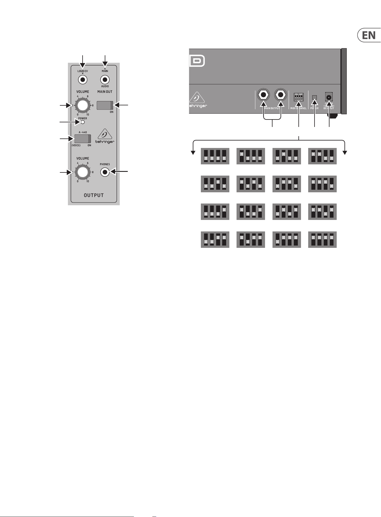
3.1.6 Output Section
(42) A-440 - use this to turn on an output tuning signal of 440 Hz concert
pitch. This switch can also be used to enter various modes during turn-on
(see the Overview section of this manual for more details).
(43) POWER LED - this LED shows when power is applied and the synthesizer
is turned on. It is also used to indicate the current status when changing
modes
(44) VOLUME - adjust the overall volume level of the synthesizer output.
(45) VOLUME (HEADPHONE) - adjust the overall volume level of the PHONES
output.
(46) PHONES - connect your headphones to this 3.5 mm TRS output. Make sure
the headphone volume is turned down before putting on headphones.
(47) ON - use this to quickly turn on or Mute the main audio output of the
synthesizer.
(48) LOUD CV (INPUT) - allows connection of an external control voltage to
control the Loudness Contour.
(49) MAIN (OUTPUT) - use this 3.5 mm TRS connection to output the main
audio output. Typically it can be patched to the audio input of another
MODEL D or to the audio inputs of other modular synthesizer equipment.
If you are using the MODEL D in a Eurorack, then this is the main output,
as the rear panel output connectors are not used.
(1)
(6)
(7)
(36)
(47)
(46)
(35)
(34)
(8)
(9)
(5)
(33)
(32)
(44)
(42)
(45)
(43)
(31)
(30)
(4)
(2) (3) (17)
(10) (11) (12) (13) (14) (15) (16) (20) (21) (22)
(24)
(25)
(23)
(18) (26) (27)
(37) (38) (39) (40)
(41)
(48)
(49)
(28) (29)(19)
3.2 Rear Panel
(50) MAIN OUTPUT - connect these ¼” TRS outputs to the inputs of
your external equipment as follows (note that they are both Mono,
and not left/right):
LOW - this instrument-level mono output can connect to the
instrument-level inputs of guitar ampliers or mixers for example.
HIGH - this line-level mono output can connect to the line-level inputs
of mixers, keyboard ampliers, or powered speakers for example.
(51) MIDI CHANNEL - these 4 switches allow you to set the MIDI Channel
number from 1 to 16 (see the table above). The MIDI channel can also be
changed using MIDI SysEx commands, as shown in the MIDI SysEx tables
later in this manual. (This method is used when the MODEL D is housed in a
Eurorack, and these switches are no longer present.).
(52) POWER - turn the synthesizer on or o . Make sure all the connections are
made, and the volume is turned down before turning on the unit.
(53) DC INPUT - connect the supplied 12V DC power adapter here. The power
adapter can be plugged into an AC outlet capable of supplying from 100V
to 240V at 50 Hz/60 Hz. Use only the power adapter supplied.
(51)(50)
1 2 3 4
5 6 7 8
9 10 11 12
13 14 15 16
(52)
(53)
12 MODEL D User Manual
4. Overview
This overview will help you set up the MODEL D analog synthesizer and briey
introduce its capabilities.
4.1 Connection
To connect the MODEL D to your system, please consult the hookup examples in
this document.
Caution: Do not overload the 3.5 mm inputs. They can only accept the
correct level of voltages as shown in the specication tables. The 3.5 mm outputs
should only be connected to inputs capable of receiving the output voltages.
Failure to follow these instructions may damage the MODEL D or external units.
4.2 Software Setup
The MODEL D is a USB Class Compliant MIDI device, and so no driver installation
is required. The MODEL D does not require any additional drivers to work with
Windows and MacOS.
4.3 Hardware Setup
Make all the connections in your system. Use the rear panel MIDI switches to set
the MODEL D to a unique MIDI channel in your system. Connect the MIDI OUT
output of an external MIDI keyboard directly to the MIDI IN 5-pin DIN type input
of the MODEL D.
Apply power to the MODEL D using the supplied power adapter only. Ensure your
sound system is turned down. Turn on the MODEL D rear panel power switch.
4.3.1 Warm Up Time
We recommend leaving 15 minutes or more time for the MODEL D to warm up
before recording or live performance. (Longer if it has been brought in from the
cold.) This will allow the precision analog circuits time to reach their normal
operating temperature and tuned performance.
4.3.2 Initial Setup
A quick way of nding out if your external sound system is working, is to turn on
the A-440 switch on the MODEL D and adjust the volume control. This will send a
constant tone (440 Hz) to your external amplier and speakers.
4.4 Mixer Section
The MODEL D has three oscillators, an internal Noise generator, and an external
source input. Each of these, and any combination, are used by the MODEL D to
generate sound.
The Mixer section allows you to turn each of these sources on or o , and adjust
the volume of each to create an overall mix. Start by turning on the top switch for
Oscillator 1, and turn o the others. Adjust the volume control of Oscillator 1. In
the Output section, adjust the main volume. Now, if you play a note on your MIDI
keyboard, you should hear the sound of Oscillator 1 only.
Turn on other oscillators and/or noise and adjust their volume controls to create
a mix.
4.4.1 External Input
The audio from an external source can be connected to the External Input
connector to play into the mixer section, and the volume can be adjusted using
the EXT IN VOLUME knob, and selected using the adjacent selector switch.
If nothing is connected to the external input, then instead of any external audio
coming in at this point, the main MODEL D output is automatically connected
here. This creates a feedback path from the output back into the mixer section,
to get extra phat bass or extra crunch. In this case, the EXT IN volume control will
adjust the level of the incoming main audio fed back into the mixer section. The
level is still dependent on the setting of the main output volume knob (44) and
the position of the main ON switch (47). Give it a try!
4.5 Oscillator Section
In the Oscillator section, adjust the Range knob and you will hear the sound of the
various octaves. Adjust the wavetype and listen to the dierences.
The oscillator modulation switch allows the oscillator frequency to be modulated
by the modulation mix.
The OSC 3 switch allows its frequency to be aected by, or be independent of, the
notes played on the keyboard, and the modulation and pitch wheels.
Note: The TUNE knob and OSCILLATOR-2 and -3 FREQUENCY knobs are marked in
units of semitones as a general guide.
4.6 Filter Section
Play with the Cuto Frequency, Emphasis, and Contour, and listen to their eects
on the sound. Adjust the Attack, Decay, and Sustain; they aect the cuto
frequency with time, while a note is played.
The lter decay switch aects the decay after a note is released. The 2 keyboard
switches aect how much the lter is aected by the frequency of notes that are
played.
If the lter modulation switch is ON then the lter section is modulated by the
modulation mix.
4.7 Loudness Contour Section
In this section, adjust the Attack, Decay, and Sustain; they aect the overall level
with time, while a note is played. The loudness decay switch aects the decay in
level after a note is released.
13 MODEL D User Manual
4.8 Controllers Section
First set the 2 switches to choose from internal LFO or internal Noise, OSC 3 or the
lter envelope, and then use the MOD MIX knob to vary the mix between them.
You can experiment by rst setting the left switch to OSC 3, and turning the MOD
MIX knob to OSC 3. Then set the Oscillator 3 RANGE control to LO, and the
Oscillator Modulation switch ON. You may now be able to hear the sound of the
Oscillator 1 modulated by OSC 3. Use the MOD DEPTH knob, and/or the
Modulation wheel of your keyboard to increase the eect.
If the Filter Modulation switch is ON, listen to the eect of modulation on the
lter.
The Modulation Sensitivity curve can be chosen from hard, medium, or soft (the
default), using the SysEx commands shown later in this manual.
4.9 Special Modes
The A-440 switch can be used to set the MODEL D into various modes of
operation. This is done by turning the A-440 switch on and o a certain number
of times within the rst 5 seconds of turning on power to the MODEL D. The
number of times determines the mode, as shown in the table below. The Power
LED will show the current value by ashing fast or slow a number of times, as
shown in the table below.
The special modes are: Multi-trigger, Note Priority, and Poly Chain operation.
A-440
Press the A-440
switch:
Mode Power LED FLashing
On and o Multi-trigger ON Flashing fast twice
Multi-trigger OFF Flashing slow twice
On and o and on Note Priority
LAST/LOW/HIGH
Flashing 3 times
On and o,
On and o
Poly Chain ON Flashing fast four times
Poly Chain OFF Flashing slow four times
4.9.1 Multi-Triggering
Multi-triggering - On: playing a new note will change the pitch and also
trigger the lter and loudness contour envelopes.
Multi-triggering - O (default, Legato): playing a new note will change
the pitch, but with no new triggering unless all notes are released. For
example, you can play a note and hold it down, and any new note will play
and use the envelopes of the note being held. The second note will often
play after the attack and decay time of the held note has passed, so the
second note will not have the sound that the attack and decay usually give.
4.9.2 Note Priority
Note Priority - if more than one note is played at the same time, this sets
which note has priority: the last note played, the lowest (default), or the
highest.
4.9.3 Poly Chain
Poly Chain - if you have multiple MODEL D units, you can connect them
in a Poly Chain so that the rst MODEL D plays the lowest note, the second
MODEL D plays the second lowest note, and so on, to produce polyphonic
sound.
Each MODEL D must have the same MIDI channel number set using the rear
panel switches. The Poly Chain connections are shown in the diagram in the
hookup diagrams of this manual.
Only set the Poly Chain ON for the rst MODEL D. Turn it OFF if you no longer
require a Poly Chain system.
If you are only using one MODEL D, then make sure the Poly Chain is OFF.
4.10 Eurorack
The MODEL D synthesizer can be taken out of its factory chassis and tted into a
standard Eurorack case (not supplied). Please see the details shown later in this
manual.
4.11 Firmware Update
Please check our website behringer.com regularly for any updates to the
rmware of your MODEL D synthesizer. The rmware le can be downloaded and
stored on your computer, and then used to update the MODEL D. It comes with
detailed instructions on the update procedure.
4.12 Have Fun
The MODEL D has various Gate and CV inputs and outputs that allow for further
experimentation and expansion to other MODEL D units and modular synthesizer
equipment.
The SysEx features of the MODEL D allow you to set and adjust various parameters
to suit your preferences. Please see the SysEx information later in this manual.
Make copies of the patch sheet in this manual, and record your favorite settings.
With all these controls, the possibilities for musical creativity are endless, rather
like an artist with a new box of paints. We hope that you will enjoy your new
MODEL D.
14 MODEL D User Manual
5. Calibration
The MODEL D synthesizer can be calibrated and checked occasionally to ensure
that it is operating at peak perfomance. Analog circuitry can drift o with time
and temperature, and as components age.
The main printed circuit board (PCB) of the MODEL D has various test points
and miniature potentiometers (trimpots) that allow the various calibration and
adjustment procedures to be carried out. This involves lifting up the front panel
to allow access to the bottom side of the PCB.
Three main calibrations can be carried out:
1. The PITCH CV can be calibrated using a computer to send a SysEx command,
an external keyboard, and a digital DC voltmeter. See section 5.2
2. The oscillators can be calibrated using a guitar tuner or the internally-
generated A-440 concert pitch, and an external keyboard. See section 5.3
3. The Octave RANGE can be calibrated using an external keyboard. See section
5.4
We recommend that the following procedures are undertaken only
by an experienced service technician, to prevent personal injury, or
damage to the unit.
As the internal PCB trimpots are delicate, make sure the procedures are not
undertaken too many times. Damage to the trimpots is not covered under
warranty, so please take every care when adjusting them.
A-440 Reference
The MODEL D A-440 pitch is generated and regulated by the MCU and there is no
adjustment required. This set frequency is used as a reference in the following
procedure to calibrate OSC1.
Equipment required
• • Small insulated trimpot screwdriver
• • Small Phillips screwdriver
• • A at sheet of cardboard or other insulator as wide as the MODEL D. (This will
help prevent damage to the top panel when it is inverted and resting on the
bottom chassis)
The following equipment is required for the Oscillator
adjustment and Octave Range adjustment:
• • An external MIDI keyboard of at least 3 octaves including A2 and C6
• • MIDI cable
• • Pair of headphones or a sound system to monitor the main output
The following equipment for the Pitch CV adjustment:
• • Digital DC Voltmeter with a scale that can display accurately to 0.001 V
• • Laptop or desktop computer previously loaded with and running a MIDI
utility that can send SysEx commands to the MODEL D
• • USB type A to USB type B connection cable
Important Note about Reset
If you have previously adjusted the MIDI IN Transpose or MIDI Note Zero Volts,
you MUST reset the MODEL D to its factory settings before doing the following
procedures. The details of using SysEx to send the Reset command are shown on
page 30.
Preparations
Before doing the PITCH CV calibrations, become familiar with, and practice the
procedures for sending SysEx commands to the MODEL D. In this way, you will
spend less time with the calibrations.
5.1 Preliminary Procedure
Follow all steps in the order in which they are presented.
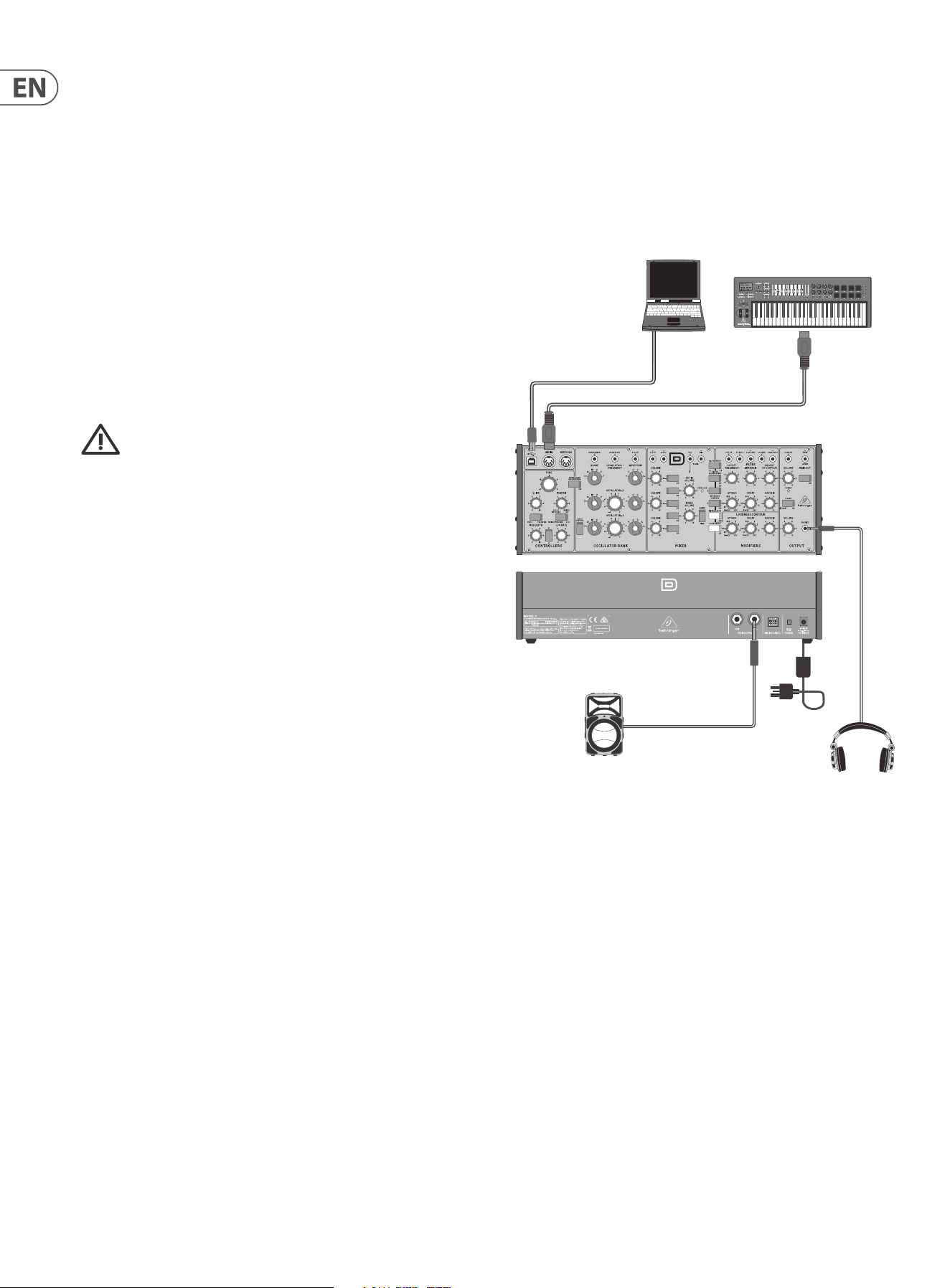
The diagram below shows the typical connections for this procedure.
5.1.1 Connections
1. Connect the external power supply adapter to the rear power input of the
MODEL D.
2. Connect the MIDI output of an external keyboard to the MIDI IN connector of
the MODEL D.
3. Connect a laptop or desktop computer to the MODEL D USB input. (This is
only required if you are doing the PITCH CV calibration, or doing a Reset.)
4. Turn down the MODEL D headphone volume knob, and connect your
headphones to the MODEL D headphones output connector. Alternatively,
you can monitor the MODEL D output using the main outputs and a suitable
sound system and speakers.
5. Turn on the MODEL D rear panel power switch and check that its Power LED
comes on.
6. Important: Leave the MODEL D turned on for approximately 30 minutes.
This will allow the circuits time to warm up and the components and
performance to stabilise with temperature. Without this warm-up time, the
calibrations will be inaccurate.
7. Set the MODEL D controls as shown on the next page.
continued on page 16
*Headphones
Power
Adapter
MOTŌR49 MIDI Keyboard/Controller
MIDI OUT
*Active Loudspeaker
*Use Headphones or a Loudspeaker
to listen to the output during
the Oscillator calibration
MIDI IN
Laptop or desktop computer
running a MIDI Utility
to send SysEx messages
(for PITCH CV calibration)
USB B
USB A
15 MODEL D User Manual
MODEL D Control Settings for Calibration
KNOBS
TUNE 0
GLIDE 0
MOD MIX *
MOD DEPTH 0
LFO RATE 0
SWITCHES
OSC3/FILTER EG *
NOISE/LFO *
SQR/TRNG *
* NO PREFERENCE
KNOBS
OSC1 RANGE 8’
OSC2 RANGE 8’
OSC3 RANGE 8’
OSC1 WAVEFORM SAWTOOTH
OSC2 WAVEFORM SAWTOOTH
OSC3 WAVEFORM SAWTOOTH
OSC2 TUNE 0
OSC3 TUNE 0
SWITCHES
OSCILLATOR MOD OFF
OSC3 CONTROL ON
KNOBS
OSC1 VOLUME 10
OSC2 VOLUME 10
OSC3 VOLUME 10
EXT IN VOLUME 0
NOISE VOLUME 0
OSC1 SELECT ON
OSC2 SELECT OFF
OSC3 SELECT OFF
EXT IN SELECT OFF
NOISE SELECT OFF
SWITCHES
WHITE/PINK *
* NO PREFERENCE
KNOBS
MAIN VOLUME *
PHONES VOLUME *
SWITCHES
MAIN OUT *
A-440 ON
* VOLUME AS NEEDED
KNOBS
CUTOFF FREQ 5
FILTER EMPHASIS 0
AMOUNT CONTOUR 0
FILTER ATTACK 0
FILTER DECAY 0
FILTER SUSTAIN 0
LOUDNESS ATTACK 0
LOUDNESS DECAY SEC
LOUDNESS SUSTAIN 10
SWITCHES
FILTER MODE LO
FLTR MODULATION OFF
KEYBRD CONTROL1 OFF
KEYBRD CONTROL2 OFF
FILTER DECAY OFF
LOUD DECAY OFF
EXTERNAL KEYBOARD
MOD WHEEL DOWN
PITCH WHEEL CENTERED
16 MODEL D User Manual
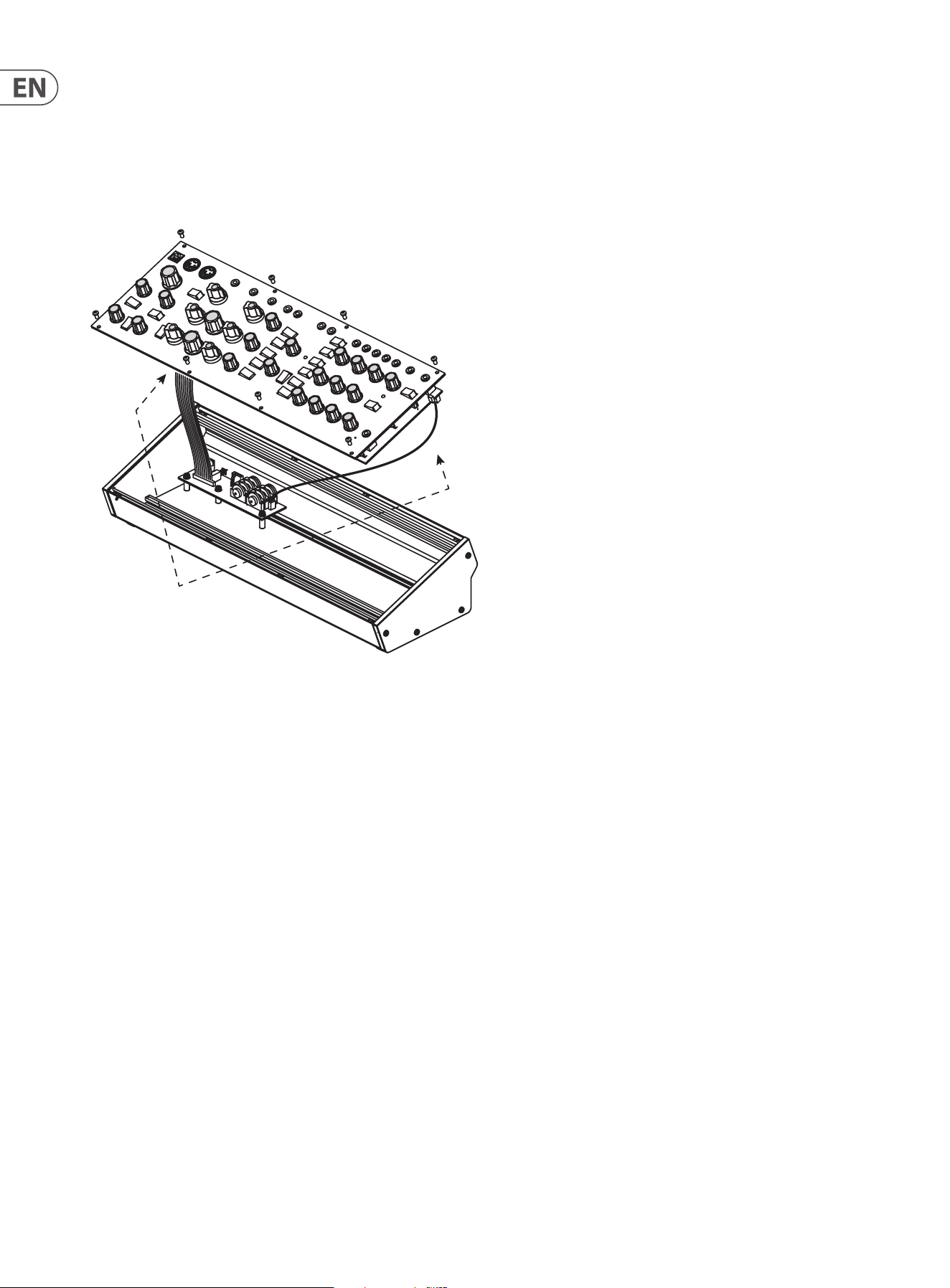
5.1.2 Lifting o the top panel
8. Turn o the MODEL D power.
9. Try and do the following steps quickly and carefully to keep any cooling
down to a minimum.
10. Carefully undo the 8 screws on the top panel as shown. There is no need to
undo any other screws.
11. Carefully lift the top panel assembly and turn it over so the PCB is facing
upwards. Be careful not to pull on the two cables from the lower side of the
main PCB. As your connections to other equipment are still in place, take care
not to pull out any cables or damage them.
12. Place a piece of cardboard or similar insulator between the controls and the
main chassis. This will help prevent damage to the controls as you lay the
top assembly onto the main chassis. To protect the wooden side panels from
being scratched, you can add some protective tape over the top edge of each
side panel.
13. Make sure that the top panel is in a secure position and that it is not liable to
be dropped or damaged, or become disconnected with its internal cables or
the MIDI cables or headphone cable.
14. Double check that the MODEL D controls are still as shown on the previous
page, in case they were moved during the top panel removal.
15. Because the main PCB is exposed, make sure you are not touching it,
and that it is not touching any metal work that may cause a short-
circuit.
16. Turn on the MODEL D rear panel power switch and check that its Power LED
comes on.
17. Do not turn o the MODEL D or let it cool down, until all the calibrations are
completed.
18. If the A-440 switch is in the ON position, you should hear the tone in your
heaphones or main system if you carefully bring the headphone volume or
main volume up.
19. Now that everything is ready, inspect the bottom surface of the PCB as
shown on the next page.
Take care not to
pull on these cables
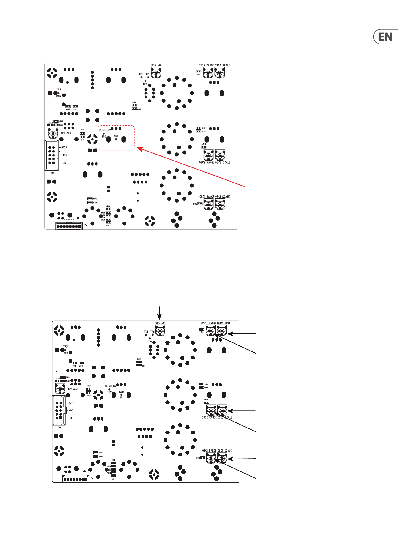
17 MODEL D User Manual
The diagram below shows the Test Points TP1 and TP2 used in the PITCH/CV
calibration. Take a look at the PCB and locate these two test points.
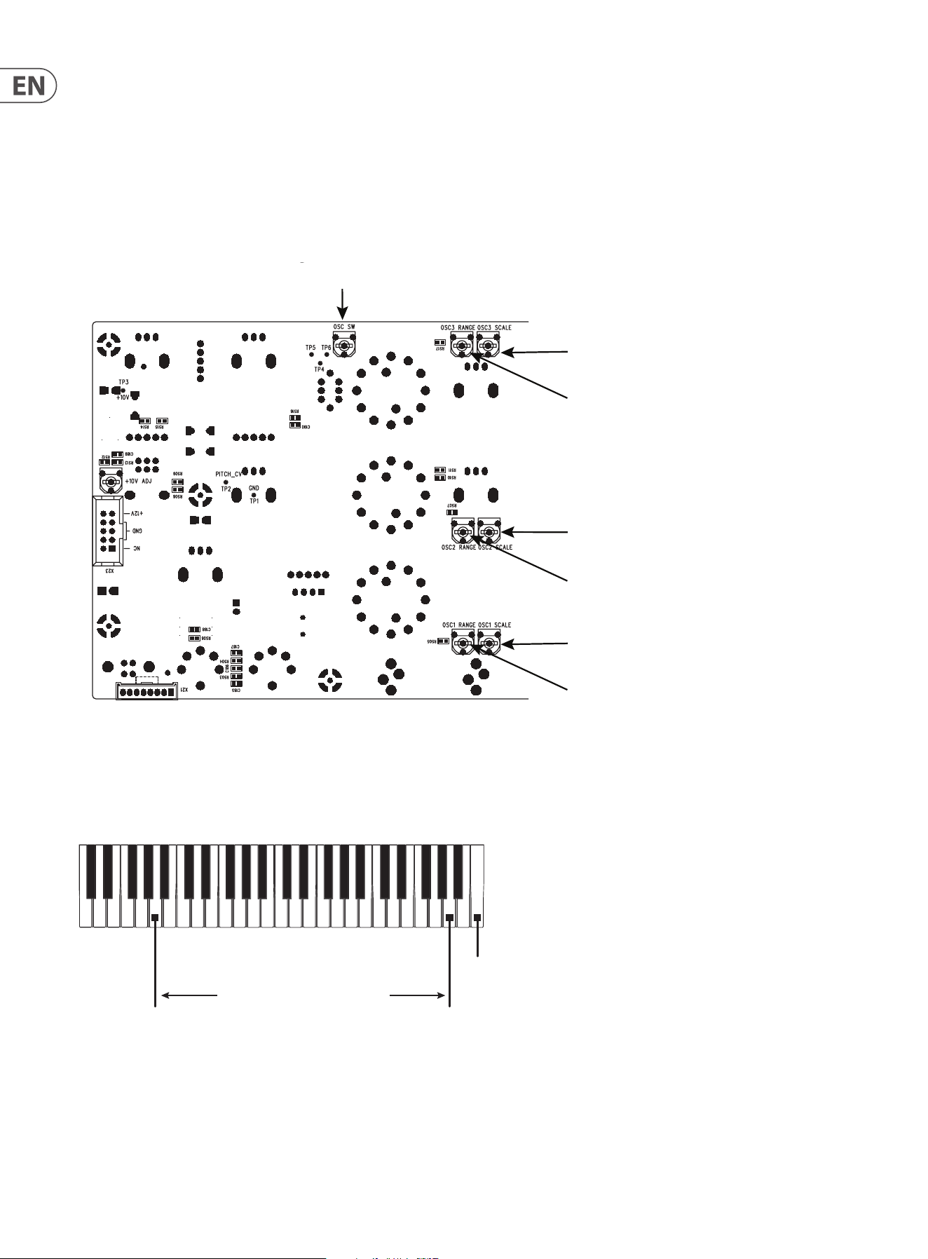
The diagram below shows the adjustment trimpots that are used in the Oscillator
and Octave range calibration procedures. Take a look at your PCB and locate
these various trimpots. (The later version of the PCB uses dierent multi-turn
trimpots.)
OSC3 Scale Adjustment
OSC3 Range Adjustmen
t
Octave Adjustment
OSC1 Scale Adjustment
OSC1 Range Adjustmen
t
OSC2 Range Adjustmen
t
OSC2 Scale Adjustment
Highest A5
Lowest A2
Highest C6
DC Voltmeter
DC
Voltmeter
0.001
18 MODEL D User Manual
5.2 PITCH CV Calibration
The PITCH CV calibration procedure uses a computer MIDI utility to send a SysEx
command to the MODEL D to put it into calibration mode.
Once in calibration mode, a digital DC Voltmeter is used to measure the voltage at
a test point while test notes are played using the external keyboard.
The meter should have a resolution of 3 or more decimal places, for example
0.001 V.
5.2.1 Putting the MODEL D into Pitch CV Calibration
Mode
The following example shows the use of the popular MIDI Utility "MIDI OX" to
send a SysEx message from your computer to the MODEL D to put it into PITCH CV
Calibration mode. (This same procedure can be used to send any SysEx message
to the MODEL D.)
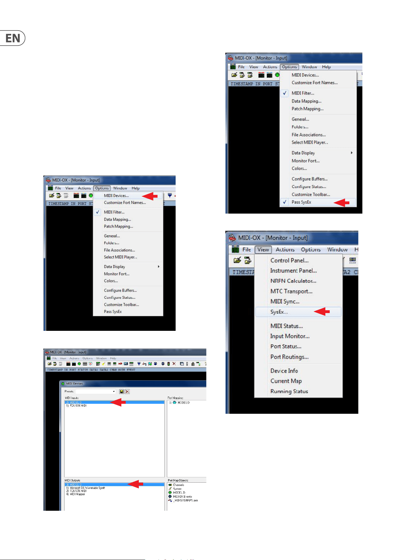
1. Run MIDI OX on your computer, and go to OPTIONS/MIDI DEVICES.
2. Select the MODEL D as the MIDI IN and MIDI OUT.
3. Select "Pass SysEx" at the bottom of the Options pull down menu. (It might
already be ticked, which is ne.)
4. In the VIEW Menu, select SysEx..
19 MODEL D User Manual
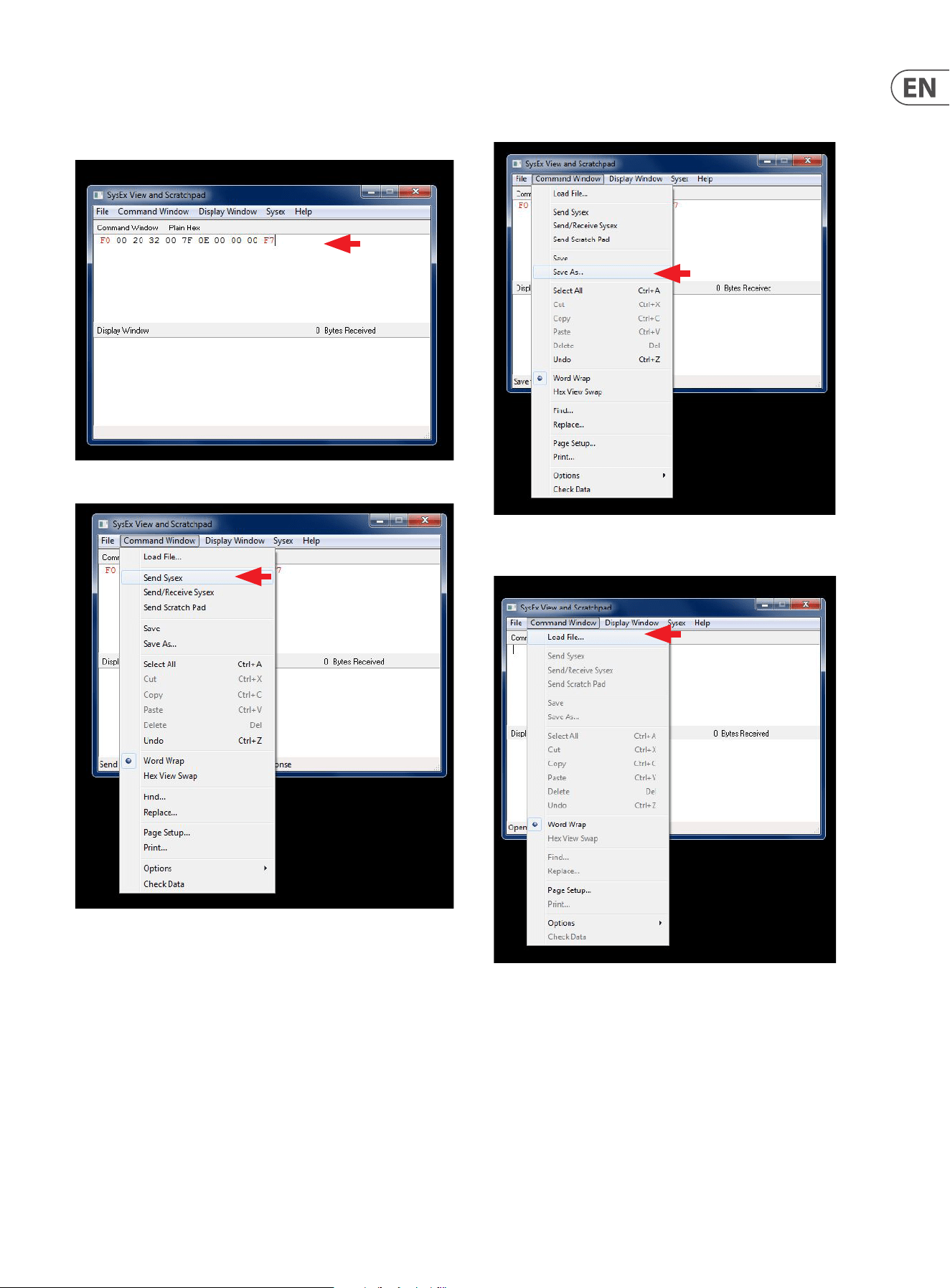
5. In the Command Window, enter the SysEx command to be sent to the
MODEL D. For PITCH Calibration, the command is:
F0 00 20 32 00 7F 0E 00 00 00 F7
6. In the Command Window drop-down menu, select Send SysEx.
7. The SysEx message will be sent to the MODEL D, and it will then be in its
PITCH Calibration mode.
8. If you wanted, you can use the SAVE AS command in the Command Window
drop down menu to save the SysEx message as a le on your computer for
later use.
9. Then use the LOAD command in the Command Window drop down menu to
recall the SysEx message from a le on your computer.
20 MODEL D User Manual
Pitch CV Calibration continued
5.2.2 Procedure
1. Follow the procedure on the previous page to put the MODEL D into PITCH
Calibration mode using SysEx.
2. Make sure that the preliminary procedures shown in section 5.1 have been
followed, and the MODEL D front panel controls and switches are set as
directed.
3. Set the Digital Voltmeter to measure a range below 10 VDC.
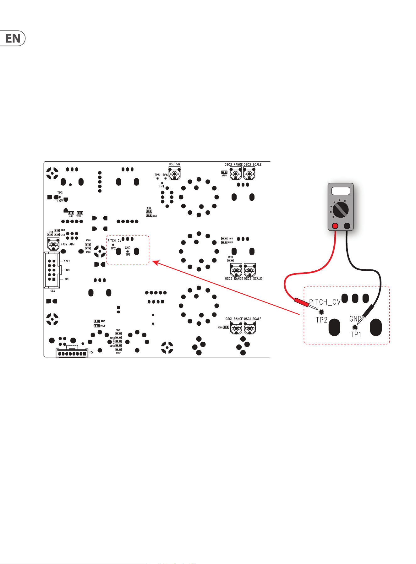
4. Locate the Test Points PITCH CV TP1 and TP2 on the bottom surface of the
main PCB, as shown below.
5. Connect the positive probe of your Voltmeter to TP2.
6. Connect the negative probe of your Voltmeter to TP1 (ground).
DC Voltmeter
DC
Voltmeter
0.001
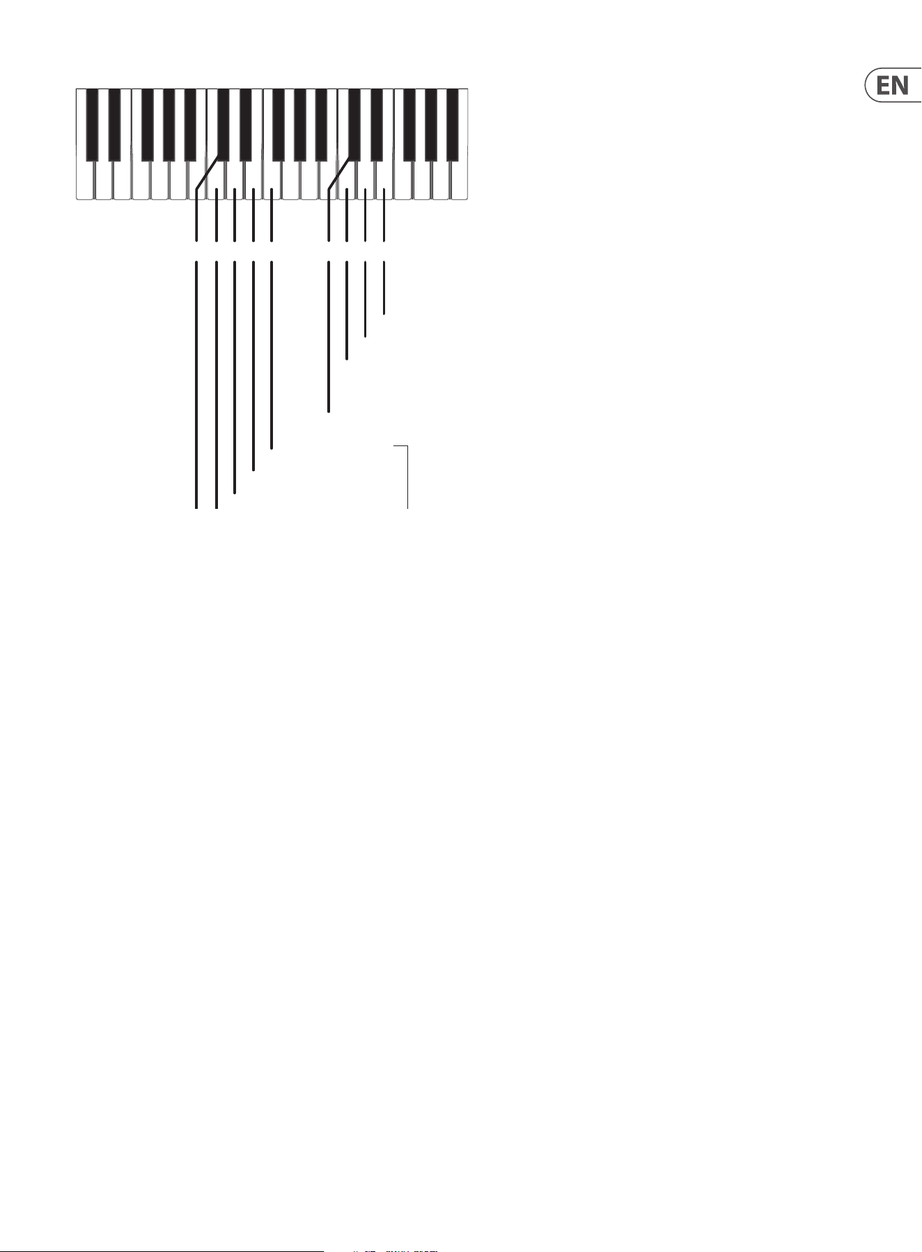
7. The keyboard diagram on the next page shows the keys used during the
PITCH CV calibration procedure.The calibration requires setting three values:
Low, Zero, and High. Various keys on the external keyboard are used to select
and trigger these three dierent calibrations, to adjust the voltage readings,
and to Save and Exit the procedure..
21 MODEL D User Manual
C4C#4 D4 E4C3C#3 D3 E3 F3
C4 Start Low Calibration. Target voltage is -2.500 Vdc
C#4 Exit Calibration Mode
D4 Start Zero Calibration. Target voltage is 0.000 Vdc
E4 Start High Calibration. Target voltage is 6.500 Vdc
C3 Decrement, Coarse
C#3 Save Calibration Settings
D3 Decrement, Fine
E3 Increment, Fine
Press to increment or decrement
or
Press and hold to automatically
increment or decrement
F3 Increment, Coarse
Low Calibration Adjustment
8. Press C4 on the external keyboard to set the Low calibration value.
9. Measure the output voltage. It should read -2.500 VDC.
10. If required, the output voltage can be adjusted to this value by pressing the
following keys. The Pitch/CV output adjustment resolution is about 2 mV
C3 = decrement coarse
D3 = decrement ne
E3 = increment ne
F3 = increment coarse
TIP: You can press and hold an increment or decrement key and (after a
brief delay) the output adjustment will repeat automatically until the key is
released.
Zero Calibration Adjustment
11. Press D4 on the external keyboard to set the Zero calibration value.
12. Measure the output voltage. It should read 0.000 VDC.
13. If required, the output voltage can be adjusted to this value by pressing the
following keys. The Pitch/CV output adjustment resolution is about 2 mV
C3 = decrement coarse
D3 = decrement ne
E3 = increment ne
F3 = increment coarse
High Calibration Adjustment
14. Press E4 on the external keyboard to set the High calibration value.
15. Measure the output voltage. It should read +6.500 VDC.
16. If required, the output voltage can be adjusted to this value by pressing the
following keys. The Pitch/CV output adjustment resolution is about 2 mV
C3 = decrement coarse
D3 = decrement ne
E3 = increment ne
F3 = increment coarse
Saving the PITCH CV Calibration Settings
17. When you are done, you must press C#3 to save your calibration settings.
Note: If you do not do this, your changes will not be saved.
Exiting the PITCH CV Calibration Procedure
18. When you are nished, you must press C#4 to exit the Calibration Mode and
return the MODEL D to normal operation.
19. If you want to do the other calibrations for the oscillators and octave range,
follow the procedures shown on the next pages.
20. If you do not want to do any other calibrations, turn o the MODEL D,
check the internal cables are securely connected, and secure its front panel
assembly back onto the chassis using the 8 screws.
Restoring the default PITCH CV settings
21. If you want to restore the Pitch CV calibration back to its factory settings,
send the SysEx command shown below. (See the previous pages for details
regarding the sending of SysEx messages.)
F0 00 20 32 00 7F 0F 00 00 00 F7
22 MODEL D User Manual
5.3 Oscillator Calibration
This calibration does not require the computer or SysEx, or the Voltmeter. An
external keyboard is used, and adjustments are made to the various trimpots.
There are two methods of oscillator calibration as shown on the next page.
The PCB and the location of the trimpots is shown below.
Note that the earlier version of the PCB has one-turn trim pots as shown, and the
newer version uses multi-turn pots that require a small at-headed screwdriver
to adjust them.
OSC3 Scale Adjustment
OSC3 Range Adjustmen
t
Octave Adjustment
OSC1 Scale Adjustment
OSC1 Range Adjustmen
t
OSC2 Range Adjustmen
t
OSC2 Scale Adjustment
Highest A5
Lowest A2
Highest C6
The diagram below shows the keyboard notes that are used in the calibrations.
Only A2 and A5 are used in the Oscillator calibration, and C6 is used in the Octave
calibration.
Alternatively, notes may be played using a DAW with a MIDI interface connected
to the MIDI IN on the MODEL D.
A2 Low Value A5 High Value
Oscillator Calibration
C6 Octave Calibration

23 MODEL D User Manual
5.3.1 Calibration Procedure using a guitar tuner
This procedure is shown in a video made by our engineers, and we highly
recommend that you take a look at the following link:
https://www.youtube.com/watch?v=-PwSISQrQEM&feature=youtu.be
1. Make sure that the preliminary procedures shown in section 5.1 of this
manual have been followed, and the MODEL D front panel controls and
switches are set as directed. Except: turn the A-440 switch OFF.
2. Connect a guitar tuner to the rear panel main 1/4" output.
Osc1 Range and Scale Calibration
3. On the PCB, locate the OSC1 RANGE and OSC1 SCALE trimpots. (See PCB
drawing on the previous page.)
4. Turn ON the OSC1 switch.
5. On your external keyboard, press and hold the A5 key and adjust the OSC1
RANGE trimpot on the PCB while observing the tuner display.
6. On your external keyboard, press and hold the A2 key and adjust the OSC1
SCALE trimpot while observing the tuner display.
7. Repeat steps 5 and 6 above until both notes are correct in the display.
This may need to be repeated several times to get right.
8. Turn OFF the OSC1 switch.
OSC 2 Scale and Range Calibration
9. On the PCB, locate the OSC2 RANGE and OSC2 SCALE pots.
10. Turn ON the OSC2 switch.
11. On your external keyboard, press and hold the A5 key and adjust the OSC2
RANGE trimpot on the PCB while observing the tuner display.
12. On your external keyboard, press and hold the A2 key and adjust the OSC2
SCALE trimpot while observing the tuner display.
13. Repeat steps 11 and 12 above until both notes are correct in the display. This
may need to be repeated several times to get right.
14. Turn OFF the OSC2 switch.
OSC 3 Scale and Range Calibration
15. On the PCB, locate the OSC3 RANGE and OSC3 SCALE pots.
16. Turn ON the OSC3 switch.
17. On your external keyboard, press and hold the A5 key and adjust the OSC3
RANGE trimpot on the PCB while observing the tuner display.
18. On your external keyboard, press and hold the A2 key and adjust the OSC3
SCALE trimpot on the PCB while observing the tuner display.
19. Repeat steps 17 and 18 above until both notes are correct in the display. This
may need to be repeated several times to get right.
20. Turn OFF the OSC3 switch.
21. This completes the Oscillator Range and Scale Calibration.
22. If you want to do the other calibrations for the octave range, follow the
procedures shown on the next pages.
23. If you do not want to do any other calibrations, turn o the MODEL D,
check the internal cables are securely connected, and secure its front panel
assembly back onto the chassis using the 8 screws.
5.3.2 Alternative Procedure using the A-440 switch
1. Make sure that the procedures shown in section 5.1 have been followed, and
the MODEL D front panel controls and switches are set as directed.
Osc1 Range and Scale Calibration
2. On the PCB, locate the OSC1 RANGE and OSC1 SCALE trimpots. (See PCB
drawing on the previous page.)
3. As set up in the preliminary procedure, make sure the A-440 switch is ON.
The A-440 test tone should be playing in your system.
4. On your external keyboard, press and hold the A5 key. Listen carefully, and
adjust the OSC1 RANGE trimpot on the PCB for zero beats.
5. On your external keyboard, press and hold the A2 key. Listen carefully, and
adjust the OSC1 SCALE trimpot on the PCB for zero beats.
6. Repeat steps 4 and 5 above until there are zero beats for either note. This
may need to be repeated several times to get this right.
7. Turn OFF the A-440 switch.
8. Make sure the OSC1 switch is left ON for the next calibration.
OSC 2 Scale and Range Calibration
9. On the PCB, locate the OSC2 RANGE and OSC2 SCALE pots.
10. As set up in the previous procedure, the A-440 test tone should be o,
and the OSC1 switch should be set on. Turn on the OSC2 switch.
11. On your external keyboard, press and hold the A5 key. Listen carefully to the
combination of OSC1 and OSC2, and adjust the OSC 2 RANGE trimpot on the
PCB for zero beats between them.
12. On your external keyboard, press and hold the A2 key. Listen carefully to the
combination of OSC1 and OSC2, and adjust the OSC2 SCALE trimpot on the
PCB for zero beats between them.
13. Repeat steps 11 and 12 above until there are zero beats for either note. This
may need to be repeated several times to get this right.
14. Turn OFF the OSC2 switch.
15. Make sure the OSC1 switch is left on, for the next calibration.
OSC 3 Scale and Range Calibration
16. On the PCB, locate the OSC3 RANGE and OSC3 SCALE pots.
17. As set up in the previous procedure, the A-440 test tone should be o,
and the OSC1 switch should be set on. Turn on the OSC3 switch.
18. On your external keyboard, press and hold the A5 key. Listen carefully to the
combination of OSC1 and OSC3, and adjust the OSC3 RANGE trimpot on the
PCB for zero beats between them.
19. On your external keyboard, press and hold the A2 key. Listen carefully to the
combination of OSC1 and OSC3, and adjust the OSC3 SCALE trimpot on the
PCB for zero beats between them.
20. Repeat steps 18 and 19 above until there are zero beats for either note. This
may need to be repeated several times to get this right.
21. Turn OFF the OSC3 switch.
22. This completes the Oscillator Range and Scale Calibration.
23. If you want to do the other calibrations for the octave range, follow the
procedures shown on the next pages.
24. If you do not want to do any other calibrations, turn o the MODEL D,
check the internal cables are securely connected, and secure its front panel
assembly back onto the chassis using the 8 screws.
24 MODEL D User Manual
5.4 Octave Range Calibration
The octave calibration ensures that the OSC1 and OSC2 Octave RANGE knobs are
in tune with each other. This calibration is done after the oscillator calibration.
1. Make sure that the preliminary procedures shown in section 5.1 have been
followed, and the MODEL D front panel controls and switches are set as
directed.
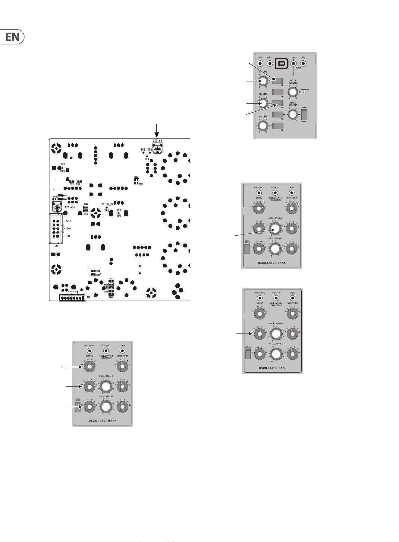
2. Turn OFF the A-440 switch, and keep the OSC1 VOLUME switch ON.
3. On the PCB, locate the OSC SW pot.
OSC3 Scale Adjustment
OSC3 Range Adjustment
Octave Adjustment
OSC1 Scale Adjustment
OSC1 Range Adjustment
OSC2 Range Adjustment
OSC2 Scale Adjustment
Highest A5
Lowest A2
Highest C6
4. Turn all the Octave RANGE knobs to the 2' position in the OSCILLATOR BANK
section.
RANGE
5. Turn on the front panel OSC2 VOLUME switch in the MIXER section. (OSC1 is
already on, OSC1 and 2 Volumes are up).
OSC2 ON
OSC1 ON
OSC1 Max
OSC2 Max
6. On your external keyboard, press and hold the C6 key. You should hear both
OSC1 and OSC2. Adjust the headphone volume or main volume as required.
7. Listen carefully, and adjust the front panel OSCILLATOR-2 Tune knob until
there are zero beats between OSC1 and OSC2.
8. Turn the front panel OSC2 Octave RANGE knob to the 8' position.
RANGE
8’
TUNE
25 MODEL D User Manual
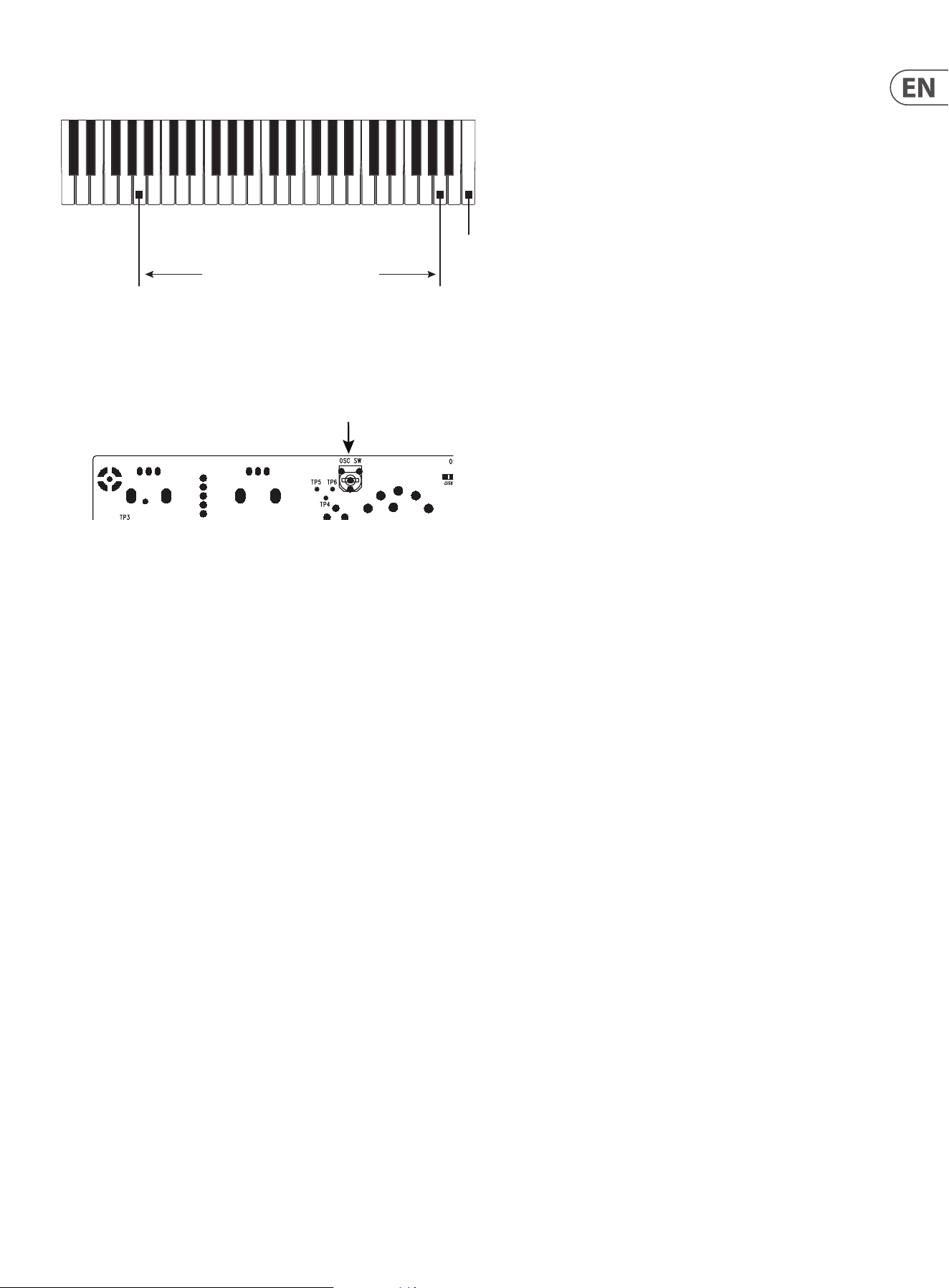
9. On your external keyboard, keep holding the C6 key.
10. Listen carefully, and adjust the OSC SW trimpot on the PCB, for zero beats
between OSC1 (Range=2') and OSC2 (Range=8').
OSC3 Scale Adjustment
OSC3 Range Adjustment
Octave Adjustment
OSC1 Scale Adjustment
OSC1 Range Adjustment
OSC2 Range Adjustment
OSC2 Scale Adjustment
Highest A5
Lowest A2
Highest C6
11. Repeat step 8 with dierent settings of the RANGE knob, and repeat steps 9
and 10 until both oscillators are in tune with each other at all settings of the
Octave RANGE knob.
12. This completes the Octave Range Calibration.
13. If you do not want to do any other calibrations, turn o the MODEL D,
check the internal cables are securely connected, and secure its front panel
assembly back onto the chassis using the 8 screws.
A2 Low Value A5 High Value
Oscillator Calibration
C6 Octave Calibration
26 MODEL D User Manual
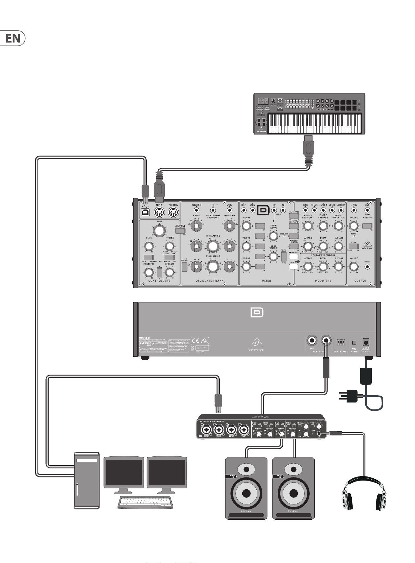
Desktop Computer
MIDI Keyboard
Headphones
Studio Monitors
Audio Interface
USB B
MIDI IN
MIDI OUT
USB B
USB A
USB A
Power
Adaptor
6. Hook-up examples
6.1 Studio System
27 MODEL D User Manual
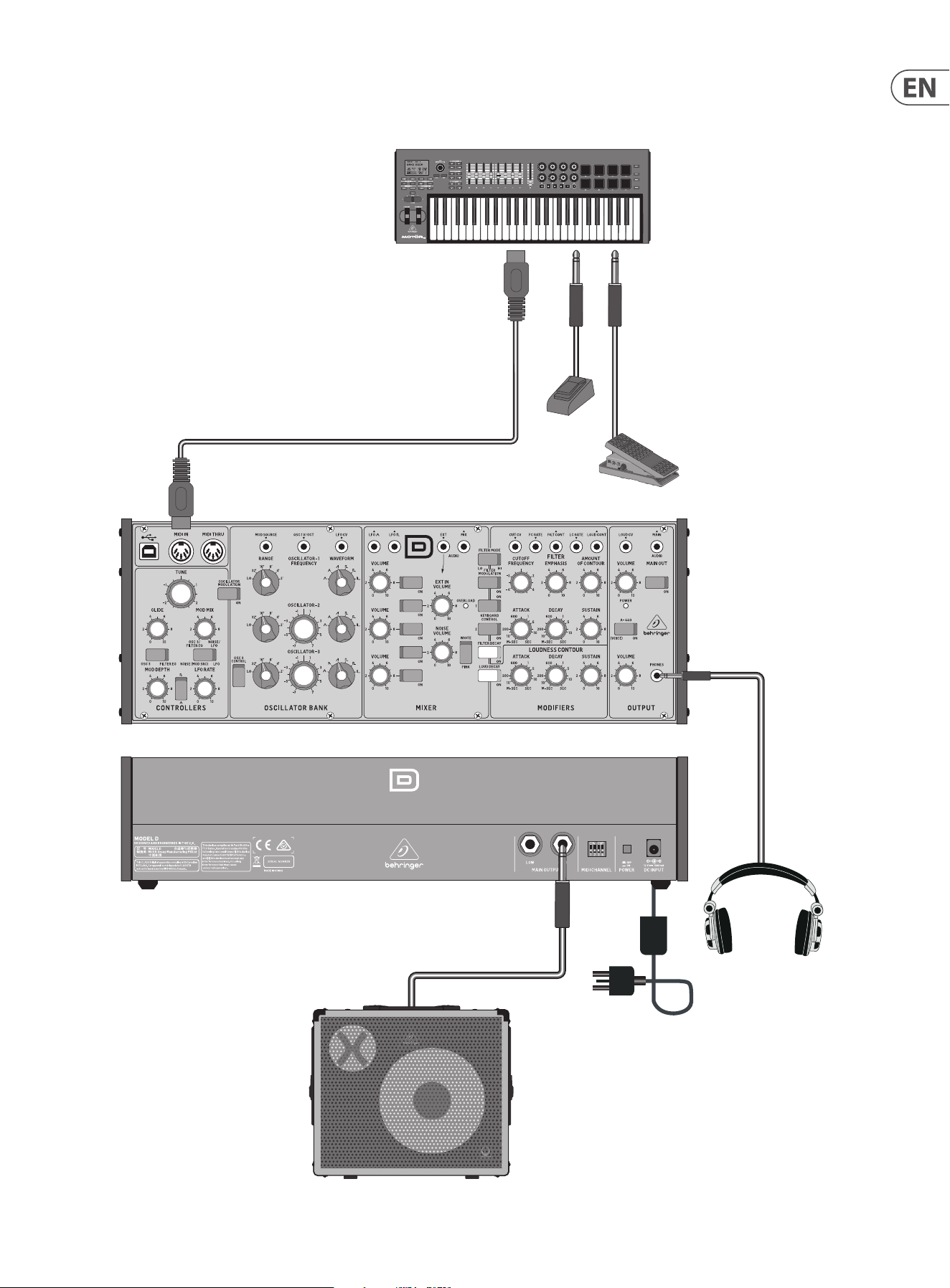
Headphones
Power
Adaptor
Expression Pedal
Footswitch
MIDI Keyboard
MIDI OUT
MIDI IN
Keyboard Amplier
6.2 Band / Practice System
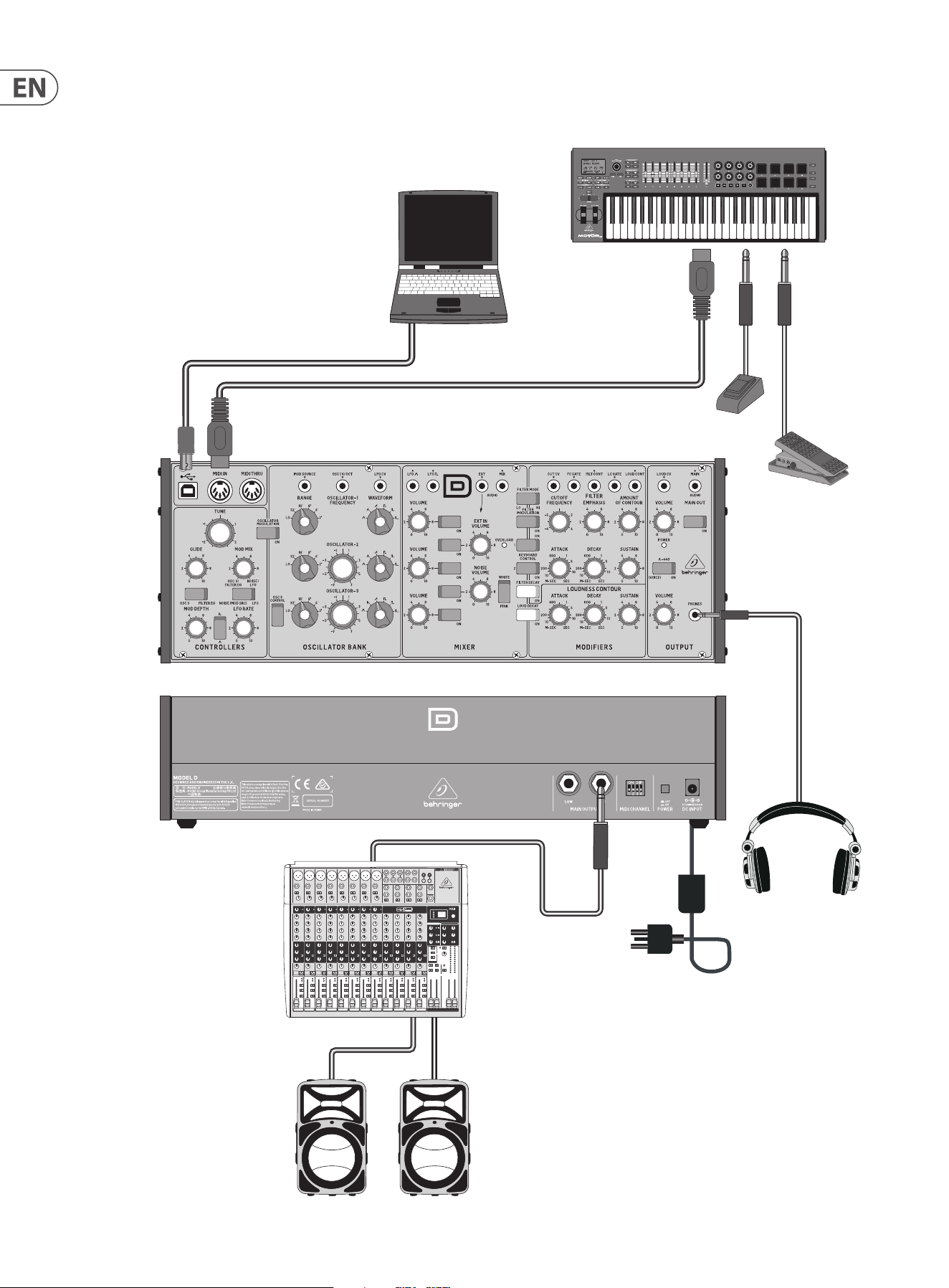
28 MODEL D User Manual
Expression Pedal
Footswitch
Headphones
Power
Adaptor
MIDI Keyboard
MIDI OUT
Mixing console
Active Loudspeakers
Laptop Computer
USB B
USB A
MIDI IN
6.3 Live System
29 MODEL D User Manual
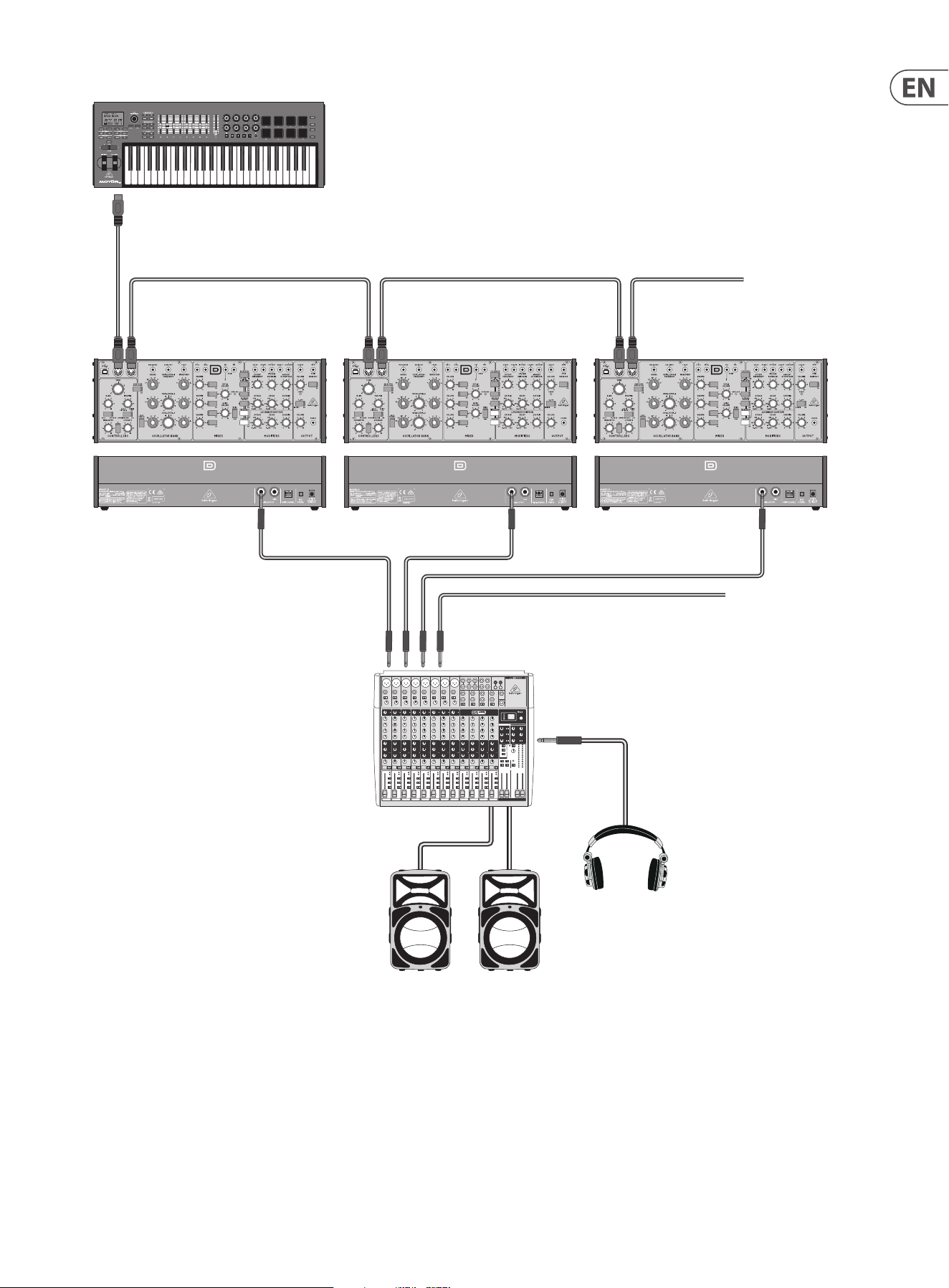
6.4 Poly Chain System
Poly Chain
If you have multiple MODEL D units, you can connect them
in a Poly Chain as shown, so that the rst MODEL D plays the
lowest note, the second MODEL D plays the second lowest
note, and so on, to produce polyphonic sound.
1. Each MODEL D must have the same MIDI channel number
set using the rear panel switches.
2. Only set the Poly Chain ON for the rst MODEL D in
the chain. This is done by pressing its A-440 switch,
"on, o, on, o" within the rst few seconds of powering
on. The Power LEDs will ash fast four times when Poly
Chain is ON. The other MODEL D units will automatically
work in Poly Chain mode once the rst unit is set up like
this.
3. Adjust the controls of each MODEL D to be the same,
similar, or experiment as required.
4. If the Poly Chain system is no longer required, turn o
the Poly Chain mode of the rst MODEL D by repeating
step 2. The Power LEDs will ash slowly four times when
Poly Chain is OFF.
MIDI IN MIDI THRU MIDI IN MIDI THRU MIDI IN MIDI THRU
To next MODEL D
From next MODEL D
MIDI Keyboard
MIDI OUT
Mixing console
Active Loudspeakers
Headphones
30 MODEL D User Manual
7. System Exclusive Commands
Some parameters in the MODEL D synthesizer can be changed using MIDI system
exclusive (SysEx) commands.
A MIDI utility such as the popular MIDI OX can be used to send the SysEx
command data string to the MODEL D using the USB MIDI conection between a
host computer and the MODEL D.
Section 5.2 shows a typical procedure for sending a SysEx message to the
MODEL D, and it can be used to send any of the following SysEx messages.
7.1 SysEx Data Format
The following data format is used when creating a SysEx message (with the data
beginning with F0 and ending with F7).
F0 00 20 32 aa bb cc dd ee F7
The various items in this SysEx data string are described below:
Item Description
00 20 32 Manufacturer SysEX ID number (Behringer GmbH)
aa Reserved
bb Device ID: 00-0xF (must match hardware
device ID), or 7F to address all devices.
Note: This is the same as the Poly Chain ID. It is not the MIDI Channel
cc Main parameter number (see Command Table below)
dd Sub parameter number (see Command Table below)
ee Parameter value MSB (will be zero unless the parameter value is
greater than 127)
Parameter value LSB (Range is 0 to 127) (see Command Table below)
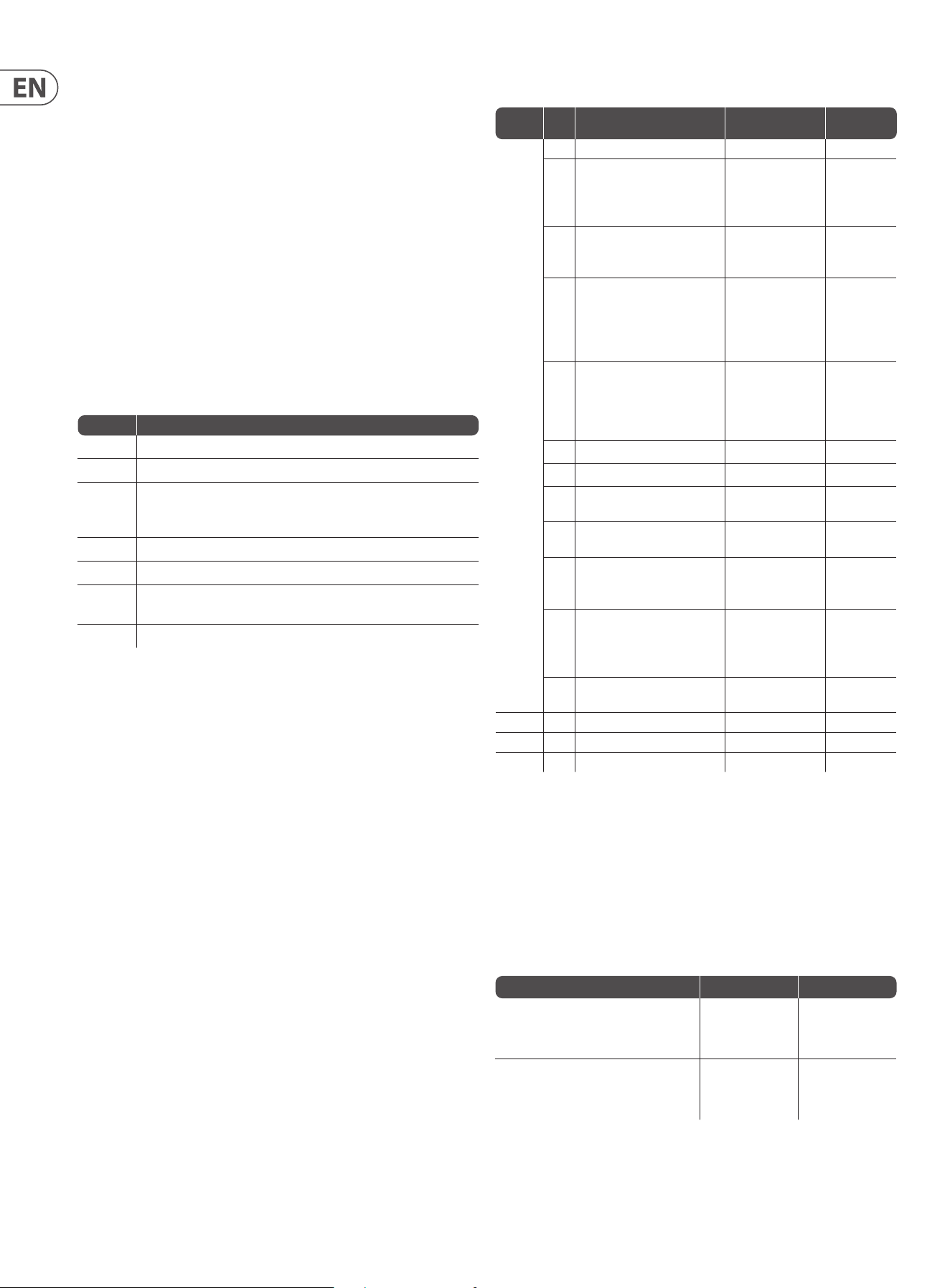
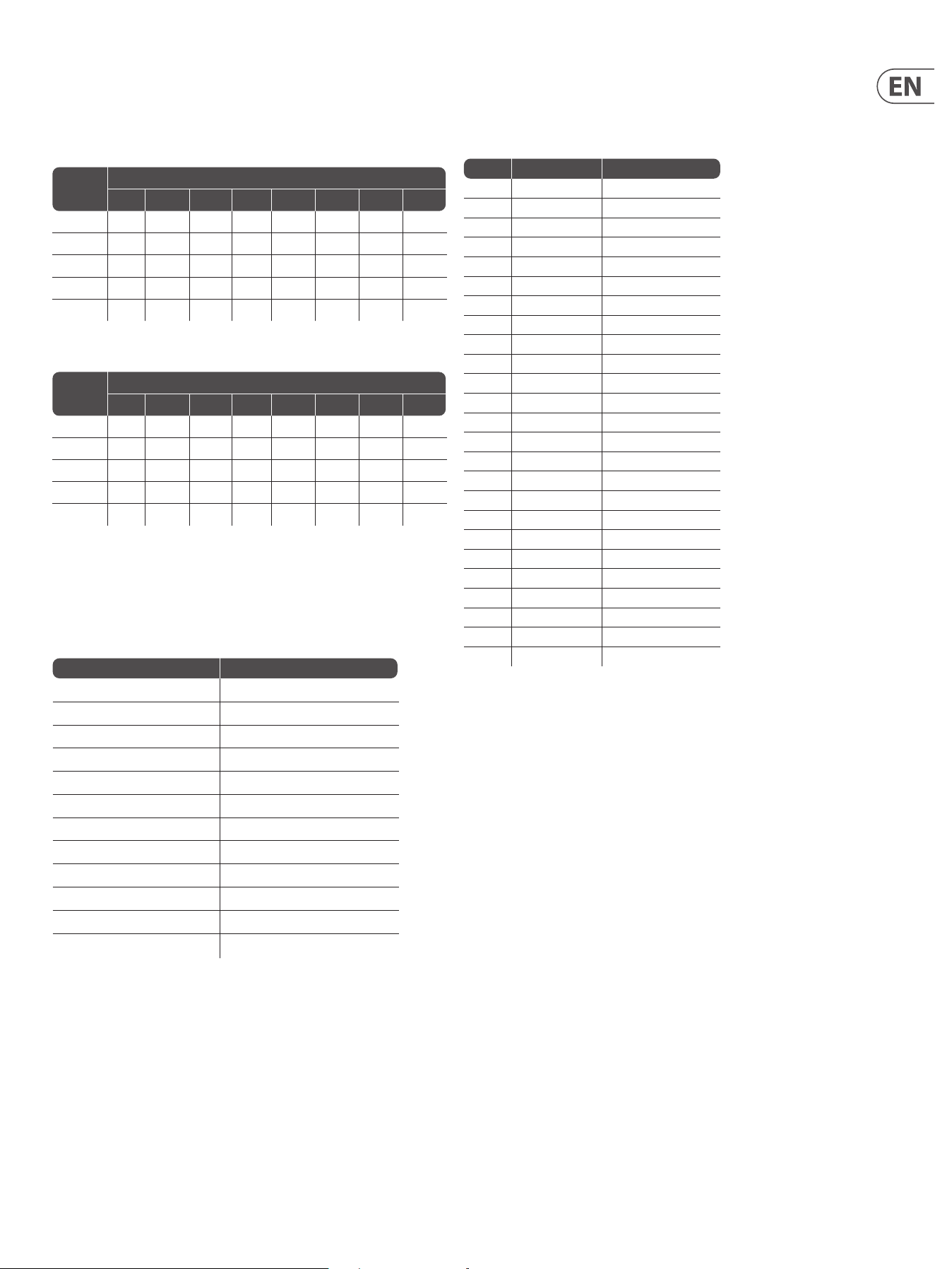
7. 2 Command Table
*Note: If you use SysEx instead of the recommended A-440 method to turn on
the Poly Chain, then the Poly Chain Device ID of other units in the chain will not
be set automatically. You have to use SysEx to set the Poly Chain ID of the rst
MODEL D to Device ID=0, the second MODEL D to ID=1, the third MODEL D to
ID=3 and so on. All MODEL D units must have the same MIDI channel.
Retriggering Style
These examples show the dierence between the old and new retriggering styles
cc (Main) dd
(Sub)
Description (Para Range) Default
0xA
Global
Setting
00 MIDI Channel 0 to 15 0
01 Key Priority
(In poly chain mode, note
priority will be restricted
to ’LOW’)
0-LOW
1-HIGH
2-LAST
0- LOW
02 Multi Trigger 0-OFF
1-ON (1.05 style)
2-ON (1.06 style)
0- OFF
03 Pitch Bend semitones
(Pitch wheel range)
Eective when pitch bend range
not xed. See “OC Pitch bend
mode” below
0 to 12 12
06 MIDI IN Transpose 0 to 24
The range is -12 to
+ 12, so 12 is no
transpose
12
07 MIDI Note Zero Volts 0 to 127 36
08 Poly Chain* see note below 0-OFF, 1-ON 0- OFF
09 Device ID
(Poly Chain ID)
0-15 0
0A Enable/Disable MIDI Channel
Switches
0- Enable
1- Disable
0- Enable
0B Modulation Curve 0- Soft
1- Med
2- Hard
0- Soft
OC Pitch Bend Mode 0- PitchBend
Range Fixed
1- PitchBend Range
Settable
0- Fixed
OD Poly Chain Style 0- New Style
1- Old Style
0- New Style
0xB Restore Global Settings
0xE Start User Pitch CV Calibration
0xF Restore Default CV Calibration
Example Old style (v1.0.5) New style (v1.0.6)
Press and hold note A. Note A is playing.
Then press and hold note B. Note B is
playing (A stop). Release note A.
Retrigger No Retrigger
Press and hold note A. Note A is playing.
Then press and hold note B. Note B is
playing (A stop). Release note B.
Retrigger Retrigger
31 MODEL D User Manual
Note: A decimal to hex conversion table is shown below. If you are using the MIDI
Transpose command, then the 3rd column shows the MIDI IN Transpose that
corresponds to each data value. For example, if you wanted a transpose of +8 as
shown in the table above, then the data sent is 14 (hex).
Value Value (hex) MIDI Transpose
0 0 -12
1 1 -11
2 2 -10
3 3 -9
4 4 -8
5 5 -7
6 6 -6
7 7 -5
8 8 -4
9 9 -3
10 A -2
11 B -1
12 C 0
13 D 1
14 E 2
15 F 3
16 10 4
17 11 5
18 12 6
19 13 7
20 14 8
21 15 9
22 16 10
23 17 11
24 18 12
Poly Chain Style
These two tables show the dierence between old and new poly chain style.
TABLE OF NOTE RESPONSE -- Old poly chain style
Poly chain
Device no.
How many notes are playing
0 1 2 3 4 5 6 7
1 O Note1 Note1 Note1 Note1 Note1 Note1 Note1
2 O Note1 Note2 Note2 Note2 Note2 Note2 Note2
3 O Note1 Note1 Note3 Note3 Note3 Note3 Note3
4 O Note1 Note1 Note1 Note4 Note4 Note4 Note4
5 O Note1 Note1 Note1 Note1 Note5 Note5 Note5
TABLE OF NOTE RESPONSE -- New poly chain style
Poly chain
Device no.
How many notes are playing
0 1 2 3 4 5 6 7
1 O Note1 Note1 Note1 Note1 Note1 Note1 Note1
2 O O Note2 Note2 Note2 Note2 Note2 Note2
3 O O o Note3 Note3 Note3 Note3 Note3
4 O O O O Note4 Note4 Note4 Note4
5 O O O O O Note5 Note5 Note5
Note: Turning on the Poly Chain will aect the note priority function
7. 3 Command Examples
Note: All command parameters should be in hexadecimal format.
Function SysEX Command String
Set MIDI Channel to 13 F0 00 20 32 00 7F 0A 00 00 0C F7
Set Key Priority to last F0 00 20 32 00 7F 0A 01 00 02 F7
Turn on Multi Trigger (1.05 style) F0 00 20 32 00 7F 0A 02 00 01 F7
Set Pitch Bend semitone to 11 F0 00 20 32 00 7F 0A 03 00 0B F7
Set MIDI IN Transpose to +8 F0 00 20 32 00 7F 0A 06 00 14 F7
Set Note C5 as Zero Volts F0 00 20 32 00 7F 0A 07 00 48 F7
Turn on Poly Chain F0 00 20 32 00 7F 0A 08 00 01 F7
Set Device ID to 5 F0 00 20 32 00 7F 0A 09 00 05 F7
Disable MIDI Channel Switches F0 00 20 32 00 7F 0A 0A 00 01 F7
Set Modulation Curve to Medium F0 00 20 32 00 7F 0A 0B 00 01 F7
Make pitch bend range eective F0 00 20 32 00 7F 0A 0C 00 01 F7
Set poly chain style to old style F0 00 20 32 00 7F 0A 0D 00 01 F7
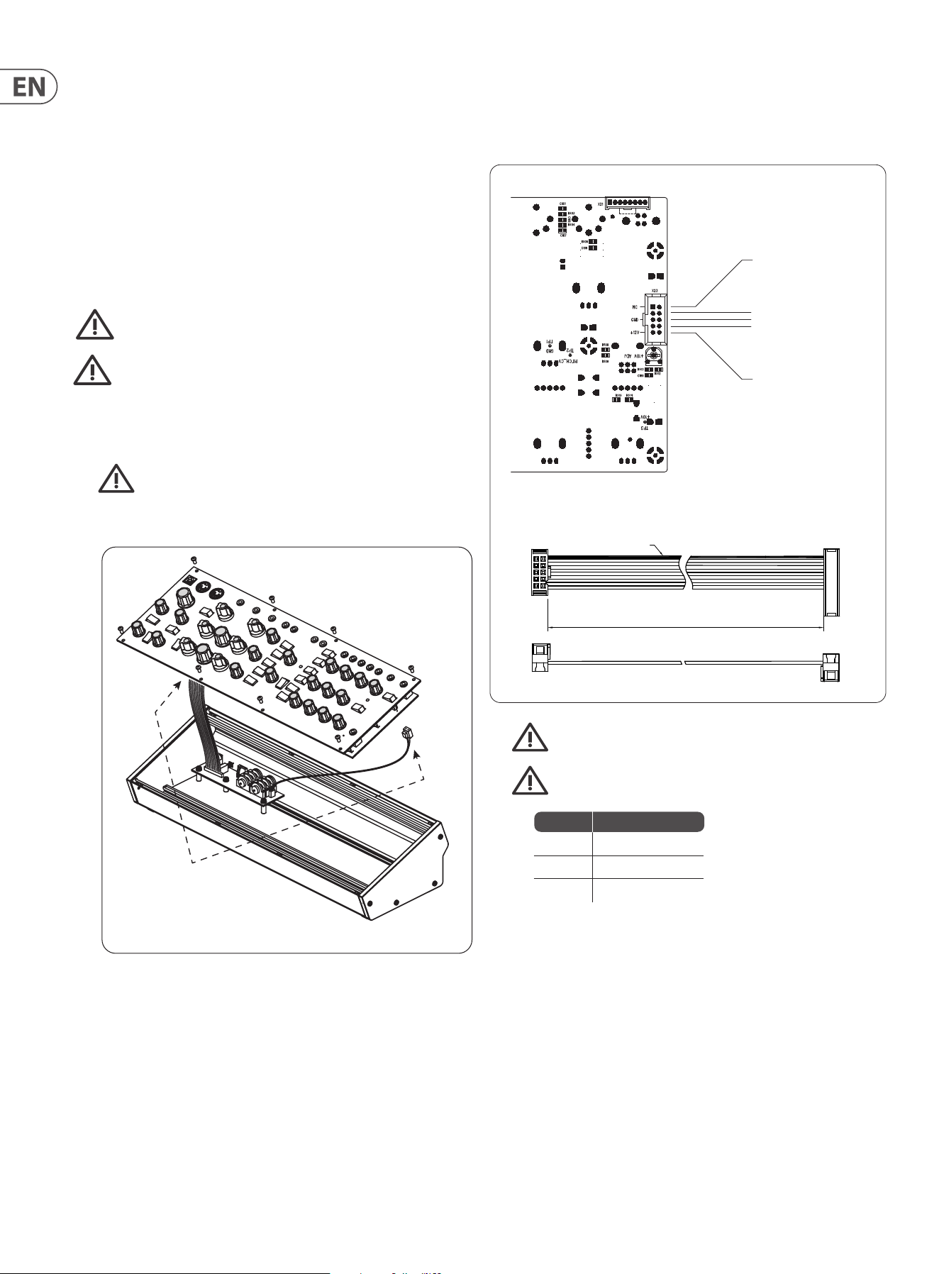
32 MODEL D User Manual
5. Securely connect the 10-pin end P1 of the supplied adapter cable to
connector X23 on the Main PCB of the MODEL D.
6. Make sure your power supply is turned o and disconnected from
the AC mains.
7. Make sure that your power supply will supply the following to the
pins of connector X23, as shown in the diagram above.
8. Securely connect the 16-pin end P2 of the supplied adapter cable to your
power supply, and double check all connections are correct.
9. Securely install the MODEL D Synthesizer into your Eurorack, using 8 screws
in the front panel.
10. Perform a full test and safety test before using the MODEL D.
11. The 3.5 mm MAIN OUT connector on the top panel is used instead of the ¼"
rear outputs which are no longer present.
400 mm ± 10
12
910
1
15
2
16
Red Stripe
Supplied Eurorack Power Supply Cable, Part # A74-0001-79446
Connect End P1 to Connector X23 on main PCB
Pins 1 and 2
No Connection
X23
X21 No Connection
Pins 3 to 8
Ground
Pins 9 and 10
+12 VDC
P1 P2
Pins Connection
1 and 2 No Connection
3 to 8 Ground
9 and 10 +12 VDC
8. Eurorack Installation
The MODEL D synthesizer can be removed from its factory chassis and installed
into a standard Eurorack chassis (not supplied). The module width is 70HP.
We recommend that this procedure is undertaken only by an experienced service
technician, to prevent personal injury, or damage to the unit.
The Eurorack case will need its own suitable power supply unit to power the
MODEL D synthesizer.
A 10-pin connector on the rear of the main PCB of the MODEL D allows the +12
VDC power supply connection to be made. A 10-pin to 16-pin adapter ribbon
cable is supplied to connect to your power supply.
Before proceeding, make sure that your power supply is capable of
supplying +12 VDC, 1 Amp.
Make sure that the connections using the supplied adapter cable will
supply the ground and power to the correct pins of X23.
8.1 Procedure
Follow all steps in the order in which they are presented.
1. Disconnect the power cord and all other connections to the
MODEL D.
2. Undo the 8 screws on the top panel as shown. There is no need to undo any
other screws.
3. Disconnect the two cables from the lower side of the main PCB of the
MODEL D, and remove the assembly from the chassis.
4. Store the chassis assembly and the power supply adaptor in a dry safe place.
Disconnect from
Main PCB

33 MODEL D User Manual
8.2 Setting the MIDI Channel
Once installed in a Eurorack, the MIDI channel number is automatically set to
channel 1 (as the MIDI switches are no longer present.)
The MIDI channel can be changed using MIDI OX or a similar MIDI utility on
your computer to send MIDI SysEx commands directly to the MODEL D via the
USB MIDI connection. Here is a brief guide to the procedure (see the MIDI SysEx
pages in this manual for the actual SysEx codes sent to the MODEL D):
1. Disable the MIDI Channel Switches by sending the appropriate SysEx
command (even though the switches are no longer present).
2. Change the MIDI Channel by sending the appropriate SysEx command.
34 MODEL D User Manual
Synthesizer Architecture
Number of voices Monophonic
Type Analog
Oscillators 3 (0.1 Hz to 20 kHz in 6 overlapping ranges)
LFO 1 (0.05 Hz to 200 Hz, up to 300 Hz with external CV
input)
VCF 1 switchable low pass or high pass (24 dB/octave
slope)
Envelopes VCA, VCF
Connectivity
MIDI In/Thru 5-pin DIN / 16 channels
USB (MIDI) USB 2.0, type B
High output ¼" TS, unbalanced, max. 0 dBu
High output impedance 1.2 kΩ
Low output ¼" TS, unbalanced, 30 dB below high output
Low output impedance 1 kΩ
Headphones 3.5 mm TRS, unbalanced, max. -3.5 dBu
Headphones output impedance 8 Ω
USB
Type Class compliant USB 2.0, type B
Supported Operating Systems Windows XP or higher
Mac OS X 10.6.8 or higher
Controllers Section
Knobs Tune: -2 to +2
Glide: 0 to 10
Modulation mix: (OSC 3 or lter EG) to (noise/ext mod
source, or LFO)
Modulation depth: 0 to 10
LFO rate: 0 to 10
Switches Modulation source: OSC 3 or lter EG
Modulation source: (noise or external modulation
source) or LFO
LFO waveform: triangular or square
Oscillator Bank
Knobs Range (OSC 1, 2, and 3): LO, 32', 16', 8', 4', 2'
Frequency (OSC 2 and 3): -7 to +7
Waveform (OSC 1 and 2): triangular, triangular/saw,
saw, square, wide pulse, narrow pulse
Waveform (OSC 3): triangular, reverse saw, saw,
square, wide pulse, narrow pulse
Switches Oscillator modulation on/o
OSC 3 control (by keyboard) on/o
Mixer Section
Knobs Volume (OSC 1, 2, and 3): 0 to 10
Volume (external input): 0 to 10
Volume (noise): 0 to 10
Switches OSC 1, 2, and 3: on/o
External input: on/o
Noise: on/o
Noise source: pink or white
LED Overload
Filter Section
Knobs Cuto frequency: -4 to +4
Filter emphasis: 0 to 10
Amount of contour: 0 to 10
Attack: 1 ms to 10 s
Decay: 4 ms to >35 s
Sustain: 0 to 10
Switches Filter mode: low pass/high pass
Filter modulation: on/o
Keyboard control 1: on (1⁄3) or o
Keyboard control 2: on (2⁄3) or o
Filter decay: on/o
Output Section
Loudness contour
dynamic range:
80 dB
Knobs Volume: 0 to 10
Headphone volume: 0 to 10
Amount of contour: 0 to 10
Attack: 1 ms to 10 s
Decay: 4 ms to >35 s
Sustain: 0 to 10
Switches Main output: on/o
A-440: on/o
Loudness decay: on/o
LED Power
Inputs (TS 3.5 mm)
Modulation source Noise is the modulation source if there is no
connection present
Oscillator 1 Control voltage: 1 V per octave
LFO Control voltage: -5 V to +5 V
External input Input impedance: 1 MΩ
Cuto frequency Control voltage: 0 to +5 V controls the cuto
frequency
Loudness Control voltage: 0 to +5 V controls the loudness
Filter contour Gate: +5 V input triggers the lter contour
Loudness contour Gate: +5 V input triggers the loudness contour
Outputs (TS 3.5 mm)
LFO triangular waveform +/-2 V
LFO square waveform +/-2 V
Mixer output max. 0 dBu
Filter contour 0 to +4 V
Loudness contour 0 to +4.6 V
Main audio output max. 0 dBu
Power Requirements
External power adaptor 12 VDC 1000 mA
Power consumption 7 W max.
Environmental
Operating temperature range 5°C – 40°C (41°F – 104°F)
Physical
Dimensions (H x W x D) 90 x 374 x 136mm (3.5 x 14.7 x 5.4")
Module width 70HP
Weight 1.7 kg (3.7 lbs)
Shipping weight 2.7kg (6.0 lbs)
9. Specications

35 MODEL D User Manual

36 MODEL D User Manual
10. Glossary
This glossary provides an explanation of useful symbols, terms and abbreviations.
32'/16'/8'/4'/2': Used to describe the range of an oscillator, this term originates
from pipe organs. The length of the pipe is inversely proportional to the pitch it
produces, for example, a 4' pipe is one octave higher than an 8' pipe.
ADC or A/D: Analog to Digital Converter, used to describe the process of
signal conversion
AC: Alternating Current
ADSR: Attack, Decay, Sustain and Release, an envelope with four stages.
Amplier: A circuit which increases the level of a signal.
Amplitude Modulation (AM): Modulation of the amplitude (or level) of a
sound by another signal source. AM is used to produce tremolo using a low
frequency modulation source.
Analog: Something which is proportional or similar to something else. In the
case of the synthesizer, audio electronic circuits are another form of air pressure
waves. Analog signals contain distortions from the components, topology,
circuits and designs which are often perceived as warmer and more natural than
their digitally generated counterparts.
Arpeggiator: An "Arpeggio" is a number of notes played sequentially instead of
simultaneously. Some external keyboards have an Arpeggiator that responds to a
number of keys being held by playing a sequence of notes.
Attack Time: The rst stage of an ADSR envelope, used to control the initial
part of a sound. Specied as the duration of time for an envelope to reach the
maximum level after it has been triggered on by a key press or gate signal.
Attenuate: To reduce the level of a signal.
Automation: The recording and playback of control signals.
Balanced Audio: A type of audio connection that uses the three wires in a cable
as part of a phase-cancelling arrangement to boost the signal and reduce noise.
Band: A range of frequencies.
Bandwidth: The dierence between the upper and lower frequencies of a lter.
Bass: Lower frequencies in a signal ranging from 60 Hz to 250 Hz
(Approximately B1 to B3).
Beat Frequency: When two waveforms of dierent frequencies are mixed
together, the resulting waveform will have points of constructive and destructive
interference. The beat frequency is equal to the dierence in frequencies and is
heard as a "beating" or amplitude modulation.
Beats Per Minute (BPM): Used to describe the tempo of a composition by
specifying the number of beats which should occur in every minute.
Cent: Unit of measurement for pitch tuning. There are one hundred cents
in a semitone.
Chorus: An eect which uses multiple copies of a signal played together and
slightly out of time, to create a shimmering eect. Sometimes referred to as
“Ensemble”.
Clock: A digital waveform typically square which is used as a timing source for
other components in a system.
Continuous Controller: A type of MIDI message assigned to a specic
parameter. When the parameter is adjusted a continuous controller messages are
sent. If the assigned continuous controller is received then the parameter will
be adjusted.
Control Voltage (CV): A voltage signal used to control any parameter.
Was common on synthesizers before MIDI, and is now found mostly on
modular synthesizers.
Cross-Modulation (X-Mod): Two oscillators modulating each other at the same
time. The outputs is a mix of the sum and dierence of the oscillators. The term
is also used to describe the ability for parameters of a synthesizer to be able to
modulate other parameters.
Cut-O Frequency: The frequency which a lter is set to. Beyond this frequency
(in a low-pass lter, the most common), the sound is cut o (attenuated) at a rate
set by the slope of the lter response curve.
Cycle: In a sound wave, the cycle refers to a single repetition of a wave-shape.
For example, in a square waveform, it is the time from a positive edge to the next
positive edge.
DAC or D/A: Digital to Analog Converter, used to describe the process of signal
conversion
Data: Digitally stored information
dB: Symbol for “decibel”. A unit of measurement of the loudness of sound.
SeedBu.
dBu: A unit of measurement of sound used in professional audio. Derived from
the decibel, where the “u” stands for unloaded, this unit is an RMS measurement
of voltage based on 0.775 VRMS, which is the voltage at which you get 1 mV of
power in a 600 Ohm resistor. This used to be the standard impedance in most
professional audio circuits.
DC Oset: An imbalance that sometimes occurs in A/D converters. It is a
constant voltage that is present, which can eat up headroom and cause clicks and
pops during editing.
Decay Time: The second stage of an ADSR envelope. Specied as the duration of
time for an envelope to reach the sustain level after the maximum level has been
reached during the attack stage.
Default: An initial value for parameter, i.e., the value before any changes have
been made.
Delay: An eect by which a reproduction of a signal is played back later then
itsoriginal. Primarily used for echo, but also is the basis for phasing, anging,
chorus and basic reverb type eects.
Detuning: The action of adjusting the pitch of an oscillator from a reference
point or another oscillator. When oscillators are detuned slightly they will make
the output sound "fatter" or "wider". When oscillators are detuned heavily to
note intervals it can create harmonies.
Digital Audio Workstation (DAW): A computer based recording system.
More commonly used to describe the software package used to record,
process and mix.
Digitally Controlled Oscillator: An analog oscillator circuit controlled and
monitored by a digital processor. The advantages over a VCO is increased stability
which results in far less tuning drift.
Digital Signal Processing (DSP): The numerical manipulation of signals,
usually with the intention to measure, lter, change, eect, produce or compress
continuous analog signals.
Distortion: An eect based on pushing the boundaries of what a specic
technology or implementation can achieve. At the point where technology
begins to overload, overdrive, clip, saturate or generally misbehave is where
distortion starts to appear. Examples include tape, valve, transistors, and also
digital algorithms and processes.
Dynamic: The range of levels in an audio signal, from the softest to the loudest.
Dynamic Processor: A device used to control and/or change the dynamics
of a signal.
Dynamic Range: The dierence between the lowest level and the highest level
an audio system can produce.

37 MODEL D User Manual
Eect: One of a number of audio processes that can be applied to a signal to
modify it, such as reverb, anging, phasing, delay etc.
Eects Send: A copy of the channel signal which is sent to an eects processor
in order for it to be returned.
Eects Return: An eected audio signal which is returned to mix with the
original channel signal.
Envelope Generator (EG): An envelope signal which can be adjusted to a
specic shape in order to control the way a sound behaves over time.
Equalisation (EQ): Processor used to adjust the volumes of various frequency
ranges for creative or corrective purposes.
Exponential: A mathematical function of growth or decay where the
independent variable is the exponent. This results in a "hockey stick"
shaped curve.
Expression Pedal: A Pedal which can be connected to an expression input and
used to send a control signal dependant on the position of the pedal. The control
signal can then be used to modulate other parameters, and/or to add expression.
Fader: A physical linear control also known as a slider, or slide potentiometer
which can be used to adjust a parameter.
Feedback: A loop created between an audio input and an audio output of an
audio circuit, system or processing block.
Filter: A device that attenuates certain frequencies while letting other
frequencies through. Using a lter to reduce harmonics, changes the timbre or
color of the sound.
Frequency Modulation (FM): Using one frequency to modulate another
frequency's pitch. When the modulation source is in the audio range, it can be
perceived as a change in the timbre or color of the sound. FM can be used to
create a wide range of rich and complex sounds and is often described as having
a clear and distinctive timbre.
Frequency: The number of times that a sound waves cycle repeats within
onesecond.
Fundamental Frequency: The lowest frequency of a periodic waveform.
Gain: The amount of signal level increase provided by an amplier stage.
Gate (Synthesizer): A signal used to trigger an event, such as a note
or an envelope.
Gate (Dynamics): A device used to cut o the level of a signal when it falls
below a specied threshold. Can be used to cut background noise, control reverb
tails, or creatively to produce chopping type eects.
Glide: See Portamento.
Global: The settings and parameters which govern the general operation of the
synthesizer and are not directly associated with the voice engines.
Harmonics: A series of integer-related sine waves at varying levels creating
dierent timbres. Waveforms (other than a pure sinusoidal) generate various
harmonics which help dene the character of the sound.
Hertz (Hz): A unit of frequency equal to one cycle of a wave per second.
High Pass Filter (HPF): A lter that attenuates lower frequencies from a signal,
leaving the higher frequencies unaected.
Hum: Undesirable low-frequency tone (typically 50 or 60 Hz) present in a signal
due to grounding problems or proximity to a power source or power cables.
Impedance (Z): Opposition to the ow of alternating current in a circuit,
measured in Ohms.
Insert: A point in a processing chain where a device can be inserted.
Keyboard: A range of keys, arranged in order of ascending pitch, which enables
the synthesizer to be played by hand.
Keyboard Tracking: Allows the control signal from played keys to adjust
another parameter. Commonly used to open a lter as higher notes are played
which then enhances harmonics.
Kilohertz (kHz): A unit of frequency equal to one thousand cycles of a
wave per second.
Latency: A delay introduced by processing. Measured by the time it takes to
produce a signal after a request has been made. In a synthesizer, it is the time
taken to produce a note after a key has been played. In an audio interface, it is
used to measure the time it takes for an input signal to reach the processor, or for
a signal from the processor to reach the output.
Level: Used to describe the magnitude of a sound, often relative to an
arbitrary reference.
Limiter: A device used to limit the level to a range of values irrespective of the
input level.
Linear: Used in audio to describe a straight line response of circuit or
process which results in a change which is directly proportional to an
independent variable.
Line Level: A nominal operating level used by audio equipment. Professional
line level is normally +4 dBu and consumer line level is -10 dBv.
Looping: Automatically restarting a function at the end of a period of time or
dened cycle, to create a continuous loop.
Low Frequency Oscillator (LFO): An oscillator that commonly runs at a very
low speed and is used to modulate another parameter.
Low Pass Filter (LPF): A lter that attenuates higher frequencies from a signal,
leaving the lower frequencies unaected.
Mark to Space Ratio: The ratio between the positive and negative parts of a
rectangular waveform, or pulsewave.
Meter: Visual device to indicate the level of a signal.
MIDI (Musical Instrument Digital Interface): A technical standard that
describes a protocol, digital interface and connectors and allows a wide variety of
electronic musical instruments, computers and other related hardware/software
devices to connect and communicate.
MIDI Clock: A clock signal which is broadcast over MIDI to ensure that devices are
synchronised. Also known as MIDI Beat Clock or MIDI Timing Clock.
MIDI Message: Data or information transmitted from one MIDI device to
another. Each MIDI message contains at least two numbers: one that identies
the type of message being sent, and another which represents a value for the
selected type of message.
Midrange: Frequencies in a signal ranging from 250 Hz to 5 kHz
(Approximately B3 to D#8).
Mix: The balance of level between one signal and another.
Mixer: A device that blends input signals into composite signals for output.
Modular Synthesis: A synthesis system comprised of a number of modules
which can be connected in many dierent ways. Modules can perform a single
function such as an oscillator or lter or perform multiple functions.
Modulation: The process of controlling one or more properties (destinations) of
a signal using another signal (source).
Modulation Wheel (Mod Wheel): A wheel located to the left of a keyboard
that allows you to change specied parameters in real-time.

38 MODEL D User Manual
Monitors: Studio quality loudspeakers, providing an accurate representation of
the audio signals.
Mono: A single signal.
Monophonic: Only one note can be played at any given time, as there is only a
single voice.
Mute: Function that allows a signal to be silenced.
N/A: Abbreviation for "not applicable" or "not available".
Noise Generator: A circuit or process that produces a random (or aperiodic)
signal. The frequency response can dier depending on the type of noise.
Note-Priority: Determines which note is played when more notes are held
simultaneously than the number of available voices (often: low/high/last).
Octave or Oct: Unit of measurement for pitch. Every time the frequency of a
waveform doubles, the pitch increases by one octave.
Ohm (Ω): Unit of electrical resistance.
Oscillator: An electronic device which generates a periodic signal used to form
the basis of a synthesizer program.
One Shot: A single event that has to be triggered each it is required.
Output: The signal sent out by a device or process. Also used to describe the
physical socket where a signal leaves a device.
Overtone: Any frequency that is present in a waveform that is higher than the
fundamental frequency of that waveform.
Pad: A program that is usually characterized by slow attack and release times.
Panning / Pan: The positioning of a signal within a stereo image.
Parameter: A setting whose value can be changed.
Parametric EQ: A type of EQ that allows all of the parameters of equalisation to
be changed, including centre frequency, boost/cut in gain and bandwidth.
Partial: Any of the sinusoidal waveforms which form part of a complex tone.
Patch: The cables used on modular synthesizers (or synthesizers with modular
compatibility) to connect devices together. Patch cables can carry audio, gate or
control voltage signals.
Period: The time that it takes a wave to complete a full cycle. Period is calculated
by dividing 1 by the frequency
Phase: A measurement (in degrees) of the time dierence between two
waveforms, or between a single waveform and a reference point.
Phaser: An eect which uses a series of notched all-pass lters (also called
stages) to create a comb-lter response which does not always have harmonic
relationships between the notches. The result is a sweeping eect similar to a
anger but smoother and often more natural sounding.
Pink Noise: A type of signal that has equal power in each band. Human hearing
is roughly logarithmic, therefore each octave is discerned to have an equal
amount of power across the audible spectrum.
Pitch: A quality of sound that makes it possible to judge if a sound is higher or
lower than another.
Pitch Bend / Pitch Bend Wheel: Controlling the pitch of a note after it has
been played.
Pitch Shift: Alteration of pitch or frequency, but without adjusting tempo.
Pole: A section of a lter stage. The more poles a lter has, the steeper its
attenuation slope will be, and the more accurate the lter will be.
Polyphonic: Capable of playing more than one note at once.
Polyphony: The number of notes a polyphonic synthesizer can play
simultaneously.
Portamento: An adjustable performance eect that glides or bends the pitch
from one note to the next.
Post: The point for accessing audio just after it leaves a specic component or
stage. For example Post-Fader audio is aected by the fader.
Pre: The point for accessing audio just before it reaches a specic component or
stage. For example, Pre-Fader audio is not aected by the fader.
Preset: A program or part of a program that is built into synthesizer patches that
are sometimes xed and sometimes editable.
Program: A complete set of parameters and settings which the synthesizer uses
to create a specic sound.
Power Supply Unit (PSU): The component in a system which is responsible for
supplying and managing power.
Psychoacoustics: The study of the perception of sound, that is, how we
listen, our psychological responses, and the physiological eects on the human
nervoussystem.
Pulse Wave: Similar to a square wave, but without symmetry. Also known as a
"Rectangle Wave."
Pulse Width Modulation (PWM): Modulation of the pulse width (the duty
cycle of a pulse wave measured as a percentage). A pulse width of 50% has equal
positive and negative sections and is considered a square wave.
Q Factor: A bandwidth (or selectivity), of a particular band in an equalizer. The
higher the Q Factor, the wider the bandwidth.
Rate: The speed at which a particular device is operating.
Release Time: The fourth and nal stage of an ADSR envelope. Specied as the
duration of time for an envelope to reach zero after the played key is released.
Resonance: The emphasis/boost of frequencies around the cut-o point just
before attenuation starts to occur. As resonance increases, it will reach a point
where the lter will start to self oscillate, producing a signal even when there is
no input.
Reverb: An eect where the ambience of a physical space is simulated.
s: Symbol for "second," a unit of time.
Sample Rate: The number of digital samples used every second to represent an
analog waveform.
Sample Resolution (Bit Depth): The number of digital bits used to dene
the amplitude of an analog signal. Higher resolution results in greater
dynamic range.
Sawtooth: A waveform that combines an instantaneous rise or fall, followed
by a gradual linear incline or decline. The name comes from the waveform's
similarity to the teeth of a saw.
Semitone: A chromatic half-step. There are twelve semitones in an octave.
Sequencer: A programmable device or module used to arrange/sequence timed
events into musical patterns and songs.
Self-oscillation: Occurs when the resonance of a lter is increased to the point
where it will begin to generate a sine wave independently of any input.
Signal ow: The path of a signal from one module (or component of a system)
to another.
Sinusoidal / Sine Wave: Mathematical description of a smooth waveform that
contains only the fundamental frequency and has no additional harmonics. The
shape resembles the letter "S" rotated 90 degrees.

39 MODEL D User Manual
Slew Rate: The rate of change of a voltage or control signal.
Spectrum: First used to describe the full range of colors in visible light, the term
is also used to describe the full range of frequencies in the audio spectrum.
Square Wave: A symmetrical waveform that combines an instantaneous rise
or fall, followed by a positive or negative steady state. The name comes from the
waveform's similarity to a square.
Step: A step is one stage in a sequence and can be a control signal, single note,
chord or rest.
Stereo / Stereophonic: The most common method of sound reproduction
where separate channels, left and right, are used to give the impression of
direction.
Stereo-Field / Stereo Image: A virtual space created by stereo
loudspeakers/monitors.
Sub-Bass: Frequencies in a signal ranging from 10 Hz to 60 Hz (lower than C0 to
approximately B1).
Subtractive Synthesis: A technique of creating sounds by ltering waveforms
which are rich in harmonics.
Sustain Level: The third stage of an ADSR envelope. Specied as "the level an
envelope will return to, after the decay stage". The envelope will remain at the
sustain level until the played key is held.
Sustain Pedal: A Pedal containing a switch which can be connected to a sustain
input and used to send a control signal dependant on the state of the switch (On/
O). The control signal can then be used to modulate other parameters, and/or to
add expression.
Synchronisation (Sync): Coordination of timing between devices.
Sync (Tempo): A function where an cyclical event such as an LFO is synchronised
to a tempo value.
Sync (Oscillator): A function where one oscillator is synchronised to another.
The waveform of the slave oscillator is reset whenever the waveform of the
master oscillator restarts.
Sync (Arp/Seq): A function where an arpeggiator or sequencer is synchronised
to a tempo value.
Sync (Key): A function where an event is synchronised to the pressing of a key.
System Exclusive (SysEx) Messages: Multi-byte messages used to transfer a
complete program or globals, in the form of request - response.
Threshold: Level at which dynamics processing will begin to operate.
Tempo: The speed at which a composition should be played, usually expressed in
beats per minute (BPM).
Threshold: In dynamic eects, this is the level that must be passed before the
processing is engaged.
Timbre: The tone, character, or aesthetic qualities of a sound.
Transposition / Transpose: A function that allows you to shift the entire
keyboard up and down in pitch.
Treble: Frequencies in a signal ranging from 5 kHz to 20 kHz (approximately D#8
to above C10).
Tremolo: A periodic change in amplitude.
Triggering: Activation of a function, such as the start of a note, envelope, or LFO.
Tune / Tuning: The process of adjusting the root pitch of the instrument to a
specic reference frequency.
Unbalanced Audio: A type of audio connection that uses two wires in a cable
and does not oer the noise rejection qualities of a balanced system.
Unison: Two or more voices that are playing together at roughly the same pitch.
Universal Serial Bus (USB): A "plug and play" interface that provides a fast
connection between a computer and peripherals.
Volt (V): A unit of electrical potential dierential or electromotive force. A
dierence in charge between two points in a circuit. This dierence, when
combined with the rate of the charge (current) allows for the control of many
analog circuits that “synthesise” sound.
VoltageControlledAmplier (VCA): An amplier whose resultant magnitude
is controlled by a voltage.
Voltage Controlled Filter (VCF): A lter whose cut-o frequency can be
controlled by a voltage.
Voltage Controlled Oscillator (VCO): An oscillator whose cut-o frequency
can be controlled by a voltage. Typically creates the possibility of tuning drift
when used in a synthesizer.
Vibrato: A periodic change in pitch.
Voice: A physical embodiment of a complete set of OSC, Envelopes, LFOs and VCF
which can play a single note.
Waveform: A repeating signal typically created by an oscillator. A waveform can
also be random in the case of noise.
Wavelength: The shortest distance between two successive points on a wave
that are in phase. When used in audio or acoustics, the physical wavelength is
calculated by dividing the velocity of sound in air (approximately 340 m/s) by the
waveform frequency.
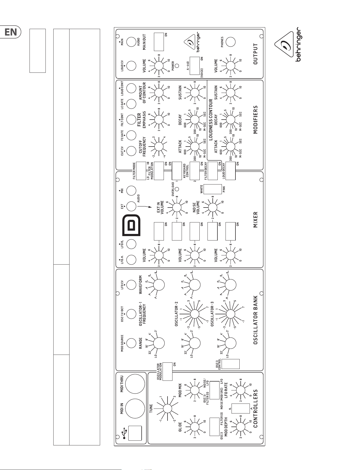
40 MODEL D User Manual
MODEL D Patch Sheet
Patch Number
DATE:
NOTES:
AUTHOR: TITLE:
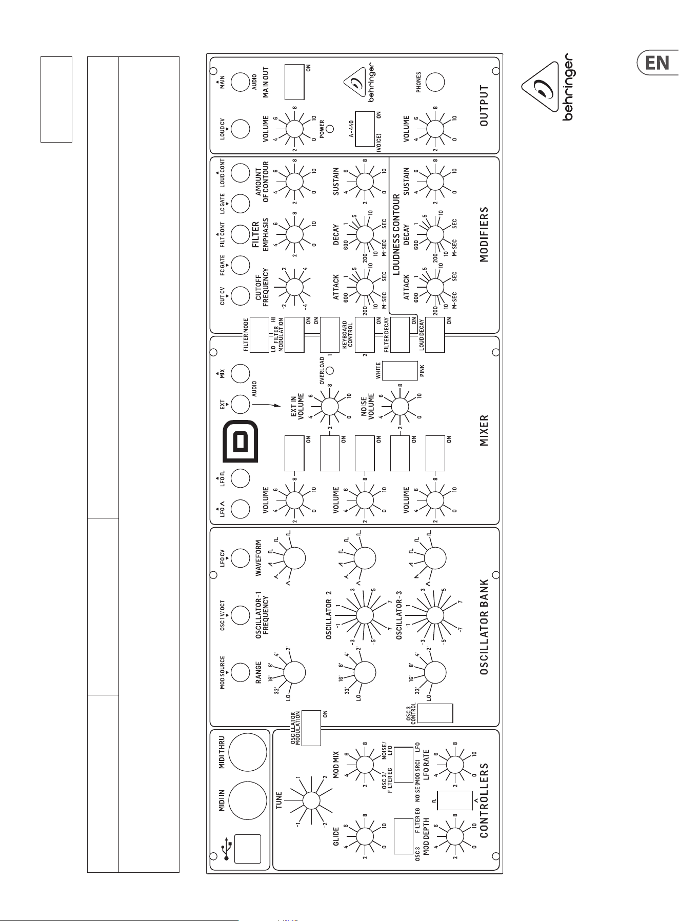
41 MODEL D User Manual
MODEL D Patch Sheet
Patch Number
DATE:
NOTES:
AUTHOR: TITLE:
42 MODEL D User Manual
FEDERAL COMMUNICATIONS
COMMISSION COMPLIANCE
INFORMATION
Responsible Party Name: Music Tribe Commercial NV Inc.
Address: 122 E. 42nd St.1,
8th Floor NY, NY 10168,
United States
Email Address: legal@musictribe.com
This equipment has been tested and found to comply with the limits for a Class B
digital device, pursuant to part 15 of the FCC Rules. These limits are designed
to provide reasonable protection against harmful interference in a residential
installation. This equipment generates, uses and can radiate radio frequency
energy and, if not installed and used in accordance with the instructions, may cause
harmful interference to radio communications. However, there is no guarantee that
interference will not occur in a particular installation. If this equipment does cause
harmful interference to radio or television reception, which can be determined
by turning the equipment o and on, the user is encouraged to try to correct the
interference by one or more of the following measures:
• • Reorient or relocate the receiving antenna.
• • Increase the separation between the equipment and receiver.
• • Connect the equipment into an outlet on a circuit dierent from that to which the
receiver is connected.
• • Consult the dealer or an experienced radio/TV technician for help.
This equipment complies with Part 15 of the FCC rules. Operation is subject to the
following two conditions:
(1) this device may not cause harmful interference, and
(2) this device must accept any interference received, including interference that may
cause undesired operation.
Important information:
Changes or modications to the equipment not expressly approved by Music Tribe
can void the user’s authority to use the equipment.
Hereby, Music Tribe declares that this product is in compliance
with Directive 2014/35/EU,Directive 2014/30/EU, Directive 2011/65/EU and
Amendment 2015/863/EU, Directive 2012/19/EU,
Regulation 519/2012 REACH SVHC and Directive 1907/2006/EC.
Full text of EU DoC is available at https://community.musictribe.com/
EU Representative: Music Tribe Brands DK A/S
Address: Gammel Strand 44, DK-1202 København K, Denmark
UK Representative: Music Tribe Brands UK Ltd.
Address: 8th Floor, 20 Farringdon Street London EC4A 4AB, United Kingdom
Behringer
MODEL D

43 MODEL D User Manual

We Hear You