
OPERATOR'S MANUAL
MODEL #201202
22-kW HOME STANDBY GENERATOR
WITH fleX CONTROLLER
™
Champion Power Equipment, Inc.
or visit championpowerequipment.com
SAVE THESE INSTRUCTIONS. This manual contains important safety precautions which should be read and understood before operating the product. Failure to do
so could result in serious injury. This manual should remain with the product.
Specifications, descriptions and illustrations in this manual are as accurate as known at the time of publication, but are subject to change without notice.
No part of this publication may be reproduced or used in any form by any means – graphic, electronic or mechanical, including photocopying, recording, taping or
information storage and retrieval systems – without the written permission of Champion Power Equipment (CPE).
4427-M-OP REV 20250423
EN
ACTIVATE YOUR WARRANTY
by registering your product:
championpowerequipment.com
SERIAL NO.

Have questions or need assistance?
Do not return this product to the store!
WE ARE HERE TO HELP!
Visit our website:
www.championpowerequipment.com
for more info:
– Product Info & Updates
– Frequently Asked Questions
– Tech Bulletins
– or –
Call our Customer Care Team Toll-Free at:
1-877-338-0999
– Product Registration
This manual must be used with Champion Power Equipment (CPE) manuals:
Installation Manual
Transfer Switch Manual
* We are always working to improve our products. Therefore, the enclosed product may differ slightly from the image on the cover.

201202 - 22-kW HOME STANDBY GENERATOR WITH fleX CONTROLLER
™
TABLE OF CONTENTS
3
TABLE OF CONTENTS
Introduction
................................................... 4
Home Standby Generator
...............................4
Safety
............................................................4
Safety Definitions ................................................. 4
Important Safety Instructions .......................5
Carbon Monoxide Hazards ........................................ 5
Installation Hazards ............................................... 6
Before Starting .................................................... 6
Operation Hazards ................................................ 6
Accidental Starting ................................................ 7
Electrical Shock Hazards ......................................... 7
Fuel Safety ........................................................ 7
Burn Hazards ...................................................... 8
Entanglement Hazards ............................................ 8
Battery Hazards ................................................... 8
Safety Symbols .................................................... 9
Safety Labels and Hang Tags ....................... 11
Safety label and Hang Tag locations ............................ 13
General Information ..................................... 14
Component Identification - Home Standby (HSB) Generator ... 14
Component Identification - Engine .............................. 15
Operation Symbols ............................................... 16
Control Panel ..................................................... 17
FCC Statement ................................................... 17
Industry Canada: CAN ICES-002/NMB-002 .................... 17
Industry Canada: ICES-003/NMB-003 .......................... 17
fleX Controller
™
................................................... 18
State .............................................................. 19
User Settings .....................................................20
Status Icons ...................................................... 22
Transfer Power Direction......................................... 23
Information Icons .................................................23
Fault Icons ........................................................ 24
Fault Protection .................................................. 28
Fault Code Reset .................................................28
Wi-Fi Setup Method ..............................................29
ATS and HSB Status Using WIFI ................................. 31
Programming fleX Controller
™
................................... 32
Setting System Time ............................................. 34
Setting Exercise Time ............................................35
Setting Brownout Delay ..........................................35
Battery Charger
..................................................36
Emission Requirements ..........................................36
Specifications .................................................... 37
Fuel System ......................................................38
Battery Requirements ............................................38
Battery Charging ................................................. 39
Model and Serial Number ........................................ 40
Operation
.....................................................40
High Altitude ......................................................40
Enclosure and Access ............................................40
Pre-Start Checklist ............................................... 42
Turning OFF the Generator .......................................42
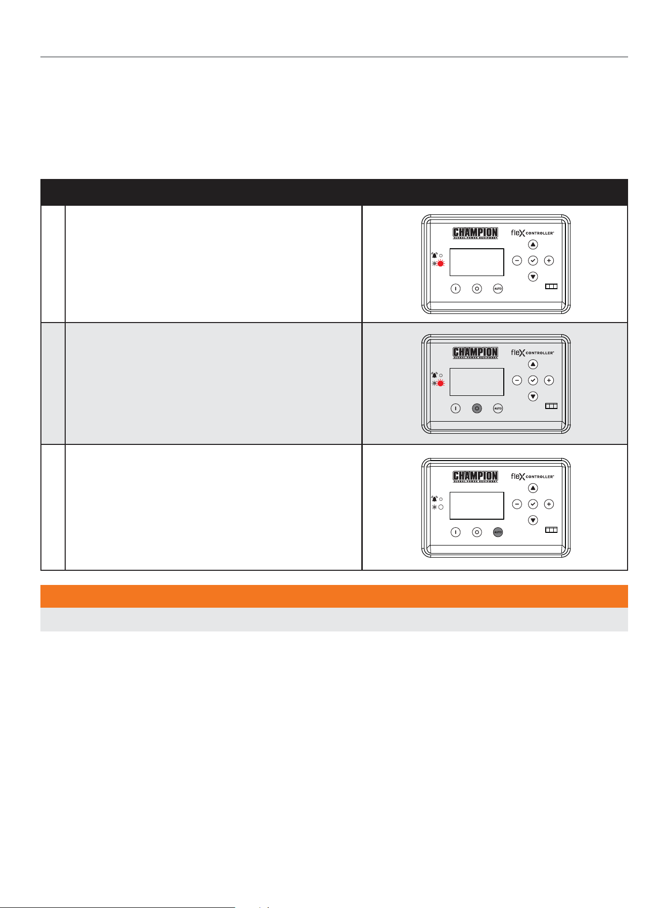
Maintenance ................................................42
Scheduled Maintenance Chart ...................................42
Spark Plug Specifications ........................................43
Oil Filter Specifications ..........................................43
Engine Oil .........................................................43
Changing the Engine Oil ......................................... 43
Inspect and Clean Engine Air Cleaner ...........................45
Spark Plug ........................................................ 45
Battery Maintenance ............................................. 46
Resetting the Maintenance Hour Meter .........................46
Corrosion Protection .............................................46
Maintenance After Submersion ..................................46
Troubleshooting HSB ...................................47
Additional Information
.................................49
Surge Protection .................................................49
Customer Familiarization Summary ............................. 49
HSB, ATS Model & Serial Reference ATS Back-up Circuits .....50
Maintenance and Service Record ............................... 51
FOR PARTS BREAKDOWN
Search by model number at
championpowerequipment.com

201202 - 22-kW HOME STANDBY GENERATOR WITH fleX CONTROLLER
™
INTRODUCTION
4
HOME STANDBY GENERATOR
This home standby generator is intended exclusively for outdoor
installation. This generator will operate using either liquified
petroleum gas (LPG) or natural gas (NG).
This generator is designed to supply typical home load such as:
Induction motors – sump pumps, refrigerators, air conditioners,
furnaces
Electronic items – televisions, computers
Household lighting
Microwaves
This generator is not intended for use in critical life support
applications.
Proper sizing of the generator is required to ensure safe operation
of appliances. Some appliances require additional wattage to start
and must be considered in the sizing of the generator.
SAFETY
Safety Definitions
The purpose of safety symbols is to attract your attention to
possible dangers. The safety symbols, and their explanations,
deserve your careful attention and understanding. The safety
warnings do not by themselves eliminate any danger. The
instructions or warnings they give are not substitutes for proper
accident prevention measures.
DANGER
DANGER indicates a hazardous situation which, if not avoided,
will result in death or serious injury.
WARNING
WARNING indicates a hazardous situation which, if not
avoided, could result in death or serious injury.
CAUTION
CAUTION indicates a hazardous situation which, if not avoided,
could result in minor or moderate injury.
NOTICE
NOTICE indicates information considered important, but not
hazard-related (e.g., messages relating to property damage).
INTRODUCTION
Congratulations on your purchase of a Champion Power Equipment
(CPE) product. CPE designs, builds, and supports all of our
products to strict specifications and guidelines. With proper
product knowledge, safe use, and regular maintenance, this
product should bring years of satisfying service.
Every effort has been made to ensure the accuracy and
completeness of the information in this manual at the time of
publication, and we reserve the right to change, alter and/or
improve the product and this document at any time without prior
notice.
CPE highly values how our products are designed, manufactured,
operated, and serviced as well as providing safety to the operator
and those around the generator. Therefore, it is IMPORTANT to
review this product manual and other product materials thoroughly
and be fully aware and knowledgeable of the assembly, operation,
dangers and maintenance of the product before use. Fully
familiarize yourself, and make sure others who plan on operating
the product fully familiarize themselves too, with the proper safety
and operation procedures before each use. Please always exercise
common sense and always err on the side of caution when
operating the product to ensure no accident, property damage,
or injury occurs. We want you to continue to use and be satisfied
with your CPE product for years to come.
When contacting CPE about parts and/or service, you will need to
supply the complete model and serial numbers of your product.
Transcribe the information found on your product’s nameplate
label to the table below
CPE TECHNICAL SUPPORT TEAM
1-877-338-0999
MODEL NUMBER
201202
SERIAL NUMBER
DATE OF PURCHASE
PURCHASE LOCATION
201202 - 22-kW HOME STANDBY GENERATOR WITH fleX CONTROLLER
™
IMPORTANT SAFETY INSTRUCTIONS
5
IMPORTANT SAFETY INSTRUCTIONS
WARNING
Cancer and Reproductive Harm – www.P65Warnings.ca.gov
Carbon Monoxide Hazards
DANGER
Generator exhaust contains carbon monoxide (CO), a colorless,
odorless, poisonous gas. Breathing carbon monoxide (CO) will
cause nausea, dizziness, fainting or death. If you start to feel
dizzy or weak, get to fresh air immediately.
GENERATOR MUST BE INSTALLED AND OPERATED
OUTDOORS ONLY.
Carbon monoxide (CO) poisoning symptoms include but are not
limited to the following:
– Lightheadedness, dizziness, blurred vision
– Physical fatigue, weakness in joints and muscles
– Mental fatigue, sleepiness, inability to concentrate or
speak clearly,
– Stomachache, vomiting, nausea
In the event of carbon monoxide (CO) poisoning:
– Seek fresh air immediately
– DO NOT sit, lie down or fall asleep.
– Alert others to the possibility of carbon monoxide (CO)
poisoning.
– If the affected person does not improve within minutes
of breathing fresh air, call 911 immediately for medical
assistance.
DANGER
Carbon Monoxide (CO) is a colorless, odorless, poisonous
gas. Breathing carbon monoxide will cause nausea, dizziness,
fainting or death.
Generator must be installed and operated outdoors only.
NEVER allow exhaust fumes to enter a confined area through
windows, doors, air intake vents or other openings of the
building.
ALWAYS avoid breathing exhaust fumes when near an
operating generator.
NEVER alter the generator or modify the exhaust system
thereby creating noncompliance with Federal and State
emissions regulations, local applicable codes, standards and
laws.
NEVER allow blockage of the engine’s air intake cooling
ventilation system. Doing so can seriously affect performance
and safe operation of the generator.
WARNING
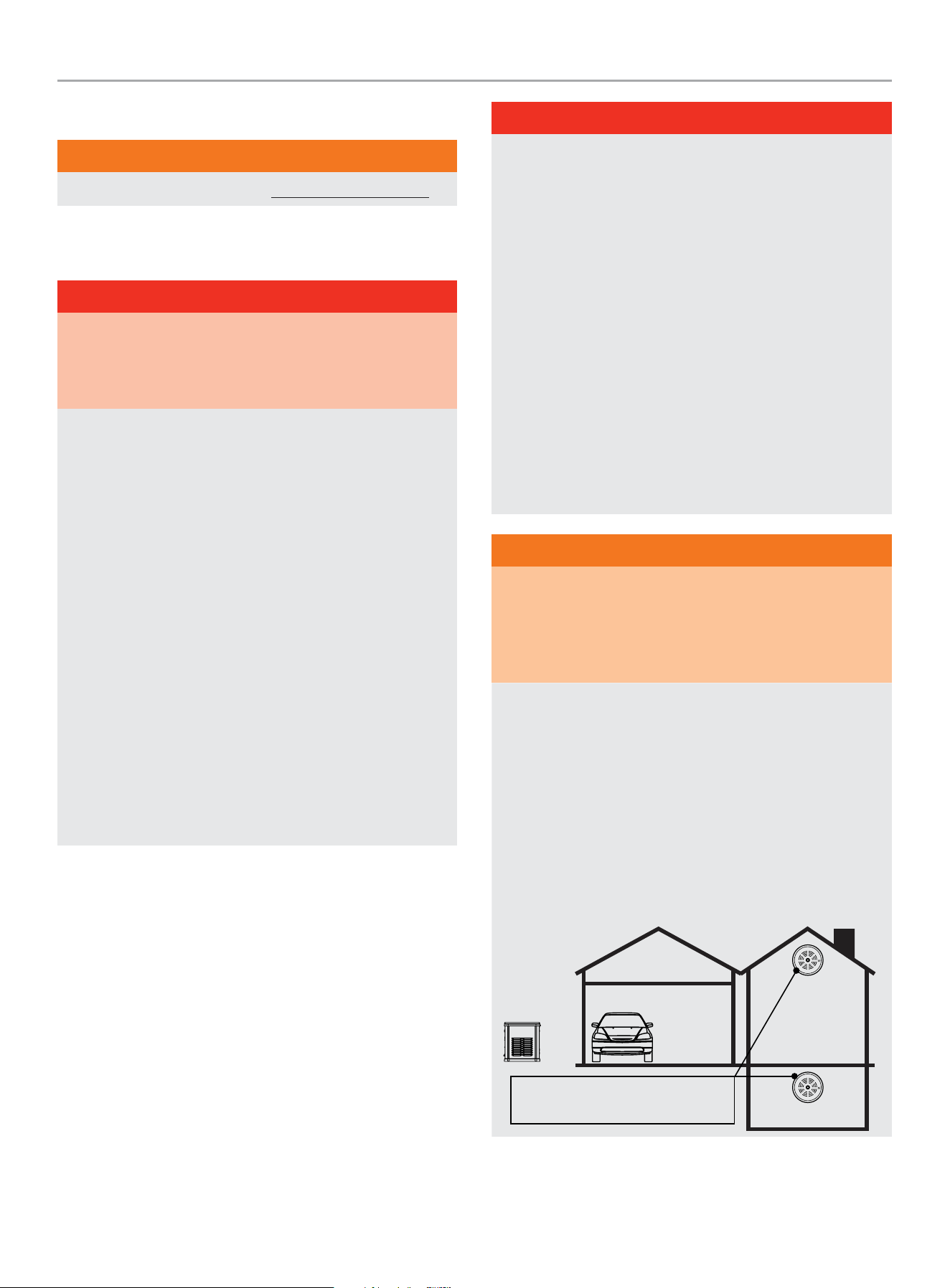
Always install a battery-operated Carbon Monoxide (CO)
detector on each level of any building or home dwelling
adjacent to the generator location following the Carbon
Monoxide (CO) detector manufacturer’s installation
instructions.
In many U.S. States and Canadian Provinces, it is required by
law to have a Carbon Monoxide (CO) detector installed on each
level of an occupied building or home dwelling.
The Carbon Monoxide (CO) detector is a device that detects
elevated levels of poisonous Carbon Monoxide (CO) gas and
will alert the occupants by flashing a visual light indicator and
an audible alarm.
The Carbon Monoxide (CO) detector alarm will not sense
smoke, fire, or any other poisonous gas other than carbon
monoxide.
Carbon Monoxide (CO) detectors
located only in living spaces.

201202 - 22-kW HOME STANDBY GENERATOR WITH fleX CONTROLLER
™
IMPORTANT SAFETY INSTRUCTIONS
6
WARNING
Smoke alarms cannot detect Carbon Monoxide (CO) gas.
To better educate yourself about all carbon monoxide risks, go
to www.takeyourgeneratoroutside.com
WARNING
Do not use generator for medical life support uses.
In case of emergency, call 911 immediately.
NEVER use this product to power life support devices or life
support appliances.
Inform your electricity provider immediately if you or anyone in
your household depends on electrical equipment to live.
Inform your electrical provider immediately if a loss of power
would cause you or anyone in your household to experience a
medical emergency.
Installation Hazards
WARNING
Always have a qualified electrician or installation technician
who are familiar with applicable safety codes, standards and
regulations to install and service the generator.
ALWAYS comply with local, state and national electrical and
building codes when installing the generator.
NEVER alter the recommended installation in a way that would
render the unit non compliant with these codes.
ALWAYS comply with regulations that Occupational Safety and
Health Administration (OSHA) has established.
ALWAYS follow the generator manufacturer’s instructions.
Before Starting
WARNING
Before operation, read and understand the features and
controls of the generator, including the safety and maintenance
sections of this manual.
The owner/operator is responsible for all periodic maintenance.
Complete all scheduled maintenance in a timely manner.
Correct any issue before operating the generator.
The owner/operator is responsible for the safe operation of this
generator.
If any portion of this manual is not understood, contact
your Champion dealer for assistance before operating the
generator.
For service or parts assistance, contact your Champion dealer
if repairs are needed.
Operation Hazards
WARNING
ALWAYS operate the generator following the manufacturer’s
instructions. Operating the generator improperly or neglecting
maintenance can result in serious injury or possible death.
DO NOT allow children or unqualified persons to operate or
service the generator.
NEVER operate the generator with the covers open. Only
operate the generator with the covers closed and secured in
place.
NEVER leave the generator covers unlocked.
NEVER work on the generator when physically or mentally
fatigued. Remain alert at all times when working on the
generator.
NEVER operate the generator while under the influence of
alcohol or drugs.
NEVER climb or step on any part or components of the
generator. Doing so may result in personal injury and cause
damage to the exhaust system and/or create leakage to the
fuel system.

201202 - 22-kW HOME STANDBY GENERATOR WITH fleX CONTROLLER
™
IMPORTANT SAFETY INSTRUCTIONS
7
Accidental Starting
WARNING
ALWAYS prevent the generator from starting while the covers
are open. The generator may crank and start at any time
without notice. Follow these steps in order:
1. Pull fuse from fleX Controller
™
panel and secure with tape
to the panel.
2. Disconnect the NEGATIVE, NEG or (-) battery cable first,
and then remove the POSITIVE, POS or (+) battery cable.
To return the generator to service, follow these steps in order:
1. Connect the POSITIVE, POS or (+) battery cable first, and
then connect the NEGATIVE, NEG or (-) battery cable.
2. Remove taped fuse from the panel and reinstall into the
fleX Controller
™
.
Electrical Shock Hazards
WARNING
The generator produces dangerous voltage. Use extreme
caution when near the generator while it is operating.
Avoid contact with bare wires, terminals and connections while
the generator is operating.
ALWAYS stand on an insulated dry surface to reduce shock
hazard if work must be done on an operating generator.
NEVER wear jewelry that can conduct electricity when working
on the generator.
NEVER handle any kind of electrical device while hands or feet
are wet, while standing in water or while barefoot.
Proper earth grounding of the frame and external electrical
conductive components is required by the National Electrical
Code (NEC). State and local codes for proper grounding may
also apply.
Avoid direct contact with an electric shock victim. Immediately
shut down the source of electrical power. If this is not possible,
attempt to free the victim from the live conductor using a
nonconducting item such as a dry board or rope. If the victim
is unconscious, apply first aid and call 911 immediately.
Fuel Safety
DANGER
PROPANE AND NATURAL GAS ARE HIGHLY FLAMMABLE
AND EXPLOSIVE.
Fire or explosion can cause severe burns or death.
Propane/LPG (liquified petroleum gas) and LPG Vapors:
– LPG is a hydrocarbon gas that exists in a liquified form
and it’s vapors are highly flammable and explosive.
– LPG and it’s vapors are under pressure and can cause a
fire or explosion if ignited.
– LPG vapors are heavier than air and will settle in low
places while dissipating.
– LPG itself is odorless and tasteless. For safety, a
chemical is added to give it an odor to help detect leaks
quickly.
– If a leak is detected, IMMEDIATELY turn OFF the gas
supply.
– In the event of an LPG fire and only when safe to do so,
first close the regulator valve OFF and then use a dry
powder extinguisher to put out the fire. This is because if
a fire is extinguished before the regulator valve is closed
OFF, then an explosion hazard condition could be created.
– Always keep the LPG cylinder in an upright position.
– LPG is a skin irritant and can cause severe cold burns
similar to frostbite.
– Always wear proper protective gloves when connecting to
and disconnecting from a propane bottle.
– Always keep LPG away from sparks, open flames, pilot
lights, heat and other sources of ignition.
DANGER
NG (natural gas) and NG Vapors:
– NG vapors are highly flammable and explosive.
– NG vapors can cause a fire or explosion if ignited.
– NG itself is odorless and tasteless. For safety, a chemical
is added to give it an odor to help detect leaks quickly.
– NG is lighter than air and will collect in higher areas.
– If a leak is detected, IMMEDIATELY turn OFF the gas
supply.
201202 - 22-kW HOME STANDBY GENERATOR WITH fleX CONTROLLER
™
IMPORTANT SAFETY INSTRUCTIONS
8
DANGER
NEVER allow any flames or smoke near the fuel system.
Wipe up any oil spills immediately.
NEVER allow any combustible materials to be near the
generator or to be left in the generator compartment.
ALWAYS keep the surrounding area near the generator clean
and free of debris.
Be sure to properly purge the fuel lines and leak-test according
to applicable codes before placing the generator in service.
Be sure to regularly inspect the fuel system for leaks. For
safety, a chemical is added to Propane/LPG/NG to give it an
odor to help detect leaks quickly. Never operate the generator
if a fuel leak is present.
Install a fire extinguisher near the generator. Keep it properly
charged and be familiar with its use. An ABC rated National
Fire Protection extinguisher is appropriate for use on standby
electric systems. Contact your local fire department with any
questions concerning the fire extinguisher.
DANGER
NEVER place a gasoline container, gasoline tank, LPG cylinder
or any combustible material in the path of the exhaust stream
during operation of the generator.
WARNING
Never use a remote or external fuel supply tank or flexible fuel
hose, or any other fuel component that is broken, cut, torn or
damaged.
Burn Hazards
WARNING
DO NOT touch hot surfaces.
ALWAYS avoid contact with hot exhaust components and
gases. Running engines produce heat. Severe burns can occur
on contact.
ALWAYS allow hot surfaces to cool to the touch.
Entanglement Hazards
WARNING
Use extreme caution when near rotating parts. Rotating parts
can entangle hands, feet, hair, clothing and/or accessories.
Traumatic amputation or severe laceration can result.
Keep hands and feet away from rotating parts.
Tie up long hair and remove jewelry.
Operate equipment with guards in place.
DO NOT wear loose-fitting clothing, dangling drawstrings or
items that could become caught.
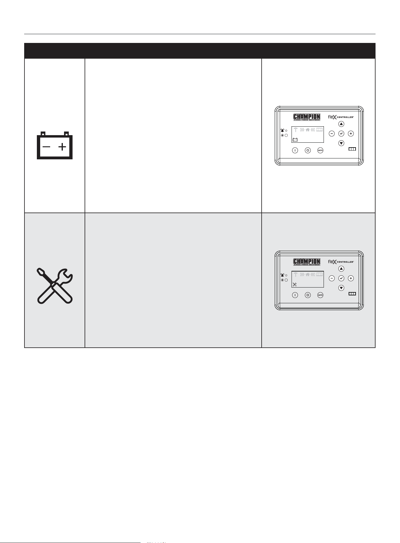
Battery Hazards
WARNING
Always read and comply with the battery
manufacturer’s recommendations for
procedures concerning proper battery use
and maintenance.
Batteries contain sulfuric acid and generate
explosive mixtures of hydrogen and oxygen
gases. Keep any device that may cause
sparks or flames away from the battery to
prevent explosion.
Always wear protective glasses or goggles
and protective clothing when working
with batteries. Always follow the battery
manufacturer’s instructions on safety,
maintenance and installation procedures.
201202 - 22-kW HOME STANDBY GENERATOR WITH fleX CONTROLLER
™
SAFETY
9
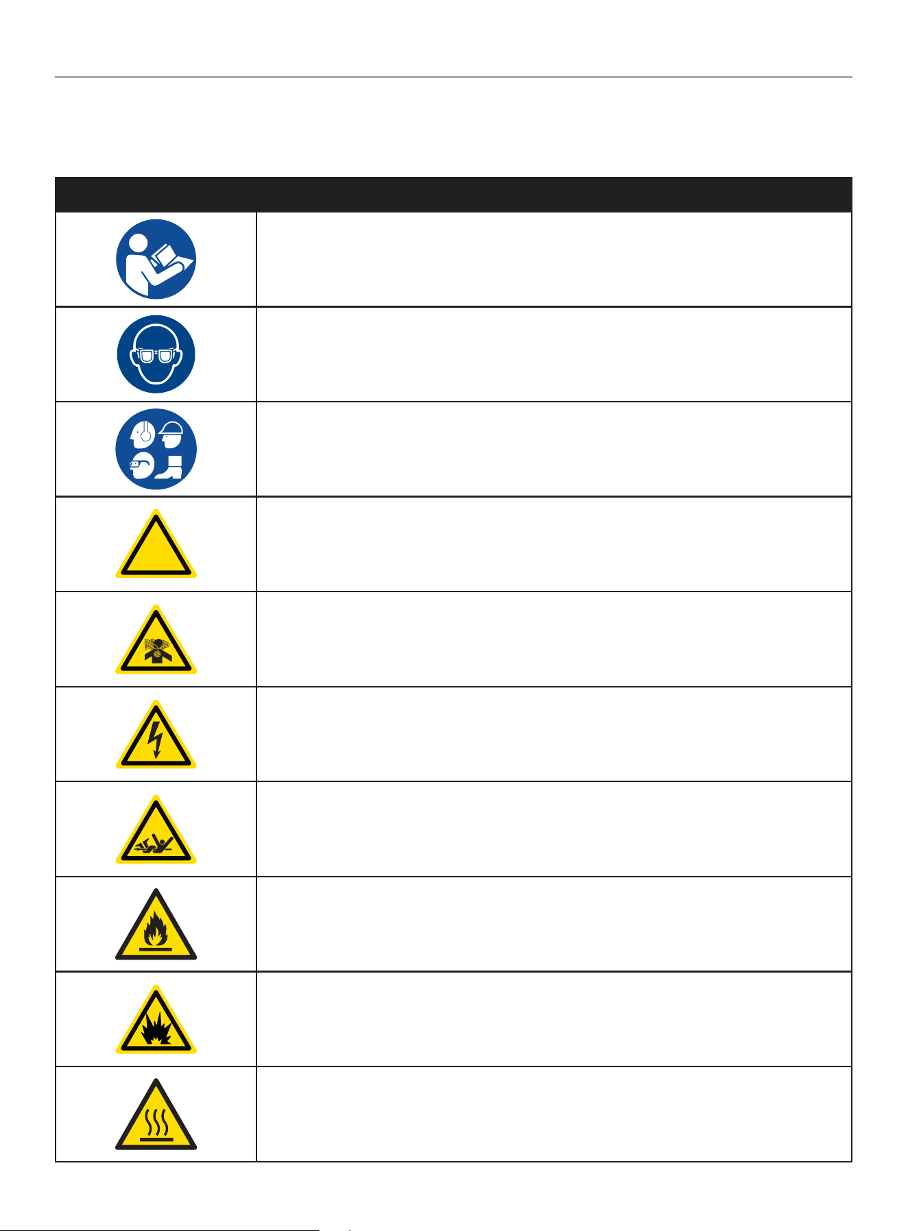
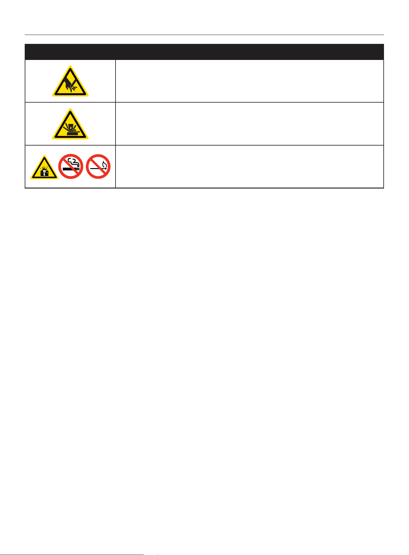
Safety Symbols
Some of the following symbols may be used on this product. Please study them and learn their meaning. Proper interpretation of these
symbols will allow you to more safely operate the product.
SYMBOL MEANING
Read Operator’s Manual. To reduce the risk of injury, user must read and understand operator’s
manual before using this product.
Eye protection. Always wear eye protection with side shields marked to comply with ANSI Z87.1
Wear personal protective equipment
!
Safety alert symbol
Asphyxiation hazard
Electrical shock hazard
Entanglement hazard
Fire hazard
Fire/Explosion. Fuel and its vapors are extremely flammable and explosive. Fire or explosion can
cause severe burns or death.
Hot Surface. To reduce the risk of injury or damage, avoid contact with any hot surface.
201202 - 22-kW HOME STANDBY GENERATOR WITH fleX CONTROLLER
™
SAFETY
10
SYMBOL MEANING
Sever hazard (rotating blade)
Crush hazard (top)
Explosion Hazard. Battery gases are explosive. Keep sparks and flames away from the battery
compartment.
201202 - 22-kW HOME STANDBY GENERATOR WITH fleX CONTROLLER
™
SAFETY LABELS AND HANG TAGS
11
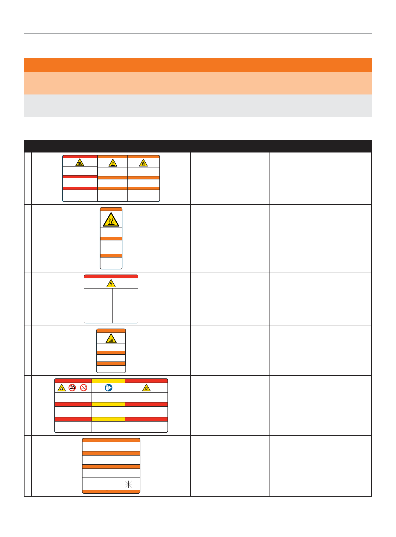
SAFETY LABELS AND HANG TAGS
WARNING
DO NOT operate the generator if there are missing or badly worn safety labels. Safety labels must be legible to alert personnel of safety
hazards.
Replace any illegible or missing label immediately. Missing safety labels must be replaced in their original position before the generator
is operated.
Labels
LABEL DESCRIPTION PART NO.
A
Poisonous Gas Hazard - Generator exh aust contain s carbon
monoxide, a colorless, odorless, poisonous gas. Breathing
carbon m onoxide will cau se nausea, dizz iness, fainti ng or
death. I f you start to fe el dizzy or weak, g et to fresh air
immediately.
Risque d’empoisonnement par le gaz - Les g az
d'échappement de la génératrice contiennent du monoxyde de
carbon e, un gaz toxique i ncolore et inod ore. L'inh alation de
monoxy de de carbone pro voque des nausée s, des
étourdissements, des évanouissements ou la mort. Si vous
commenc ez à vous sentir ét ourdi ou faible, r endez-vous
immédiatement à l'air frais.
Riesgo d e gas venenoso - Lo s gases de escap e del
generador contienen monóxido de carbono, un gas incoloro,
inodoro y venenoso. Respirar monóxido de carbono provoca
náusea s, mareos, desm ayos o la muerte. S i empieza a
sentir se mareado o débi l, busque aire fr esco inmediat amente.
DANGER
PELIGRO
2510-L-SF-E
Fire Haz ard - ALWAYS keep the sur rounding area
near gene rator clean and f ree of debris and /or dry
vegeta tion. The gener ator may create sp arks while
operating.
Risque d’incendie - Nettoyez TO UJOURS la sur face
à proximi té du groupe élec trogène et enleve z les
débris e t/ou la vegéta tion sèche. Le gr oupe
électrogène peut générer des étincelles pendant
son fonctionnement.
Riesgo d e incendio - SIE MPRE manteng a el área
circund ante cerca del gen erador limpia y libre de
escombros y/o vegetació n seca. El gener ador puede
crear chispas mientras está en funcionamiento.
WARNING
ADVERTENCIA
Burn Haz ard - DO NOT touch h ot surfaces.
Avoid con tact with exhaust component s
and gases.
Risque de brûlure - NE touchez PAS le s
surfa ces chaudes. Evitez le contat avec l es
composants et les gaz d’échappement.
Riesgo de quemaduras - NO toque las
super ficies calient es. Evite el cont acto con
los compo nentes de escape y g ases.
WARNING
ADVERTENCIA
DANGER
AVERTISSEMENT
AVERTISSEMENT
Poison, Burn and Fire
Warning
2510 -L-S F
B
2483-L-SF-C
Burn Hazard - DO NOT touch
hot surfaces. Allow the
engine and alternator to cool
to the touch before servicing.
Riesgo de quemaduras -
NO toque las superficies
calientes. Deje que el motor
y el alternador se enfríen
para tocarlos antes de
realizarles el mantenimiento.
WARNING
ADVERTENCIA
Danger de brulure - NE
TOUCHEZ PAZ les surfaces
chaudes. Laissez le moteur
et l’alternateur devenir froid
au toucher avant d’intervenir.
AVERTISSEMENT
Burn Warning 24 83 -L- SF
C
Electrical Shock - ALWAYS close
and lock the generator covers
before operating. The generator
produces dangerous voltage.
Riesgo de descarga eléctrica -
SIEMPRE cierre y trabe las tapas del
generador antes de ponerlo en
funcionamiento. El generador
produce un voltaje peligroso.
Risque de choc électrique -
Fermez et verrouillez TOUJOURS les
capots de groupe électrogène avant
d’utiliser le groupe. Le groupe
électrogène génère des tensions
dangereuses.
PELIGRO DANGER DANGER
Electrical Shock Hazard - Do not
remove this access panel. The panel
should only be removed by an authorized
Service Dealer or a qualified electrician;
high voltage inside.
Riesgo de descarga eléctrica - No
remueva este tablero de acceso. El
tablero sólo deberá ser removido por un
distribuidor de servicio autorizado o un
electricista calificado; alto voltaje al
interior.
Risque de choc électrique - N’enlevez
pas ce panneau d’accès. Le panneau ne
devrait être enlevé que par un
concessionnaire d’entretien agréé ou un
électricien qualifié; haute tension à
l´’intérieur.
4647-L-SF-B
Electrocution Warning 4 647-L-SF
D
2473-L-SF-C
Burn Hazard - DO NOT touch hot surfaces.
Avoid contact with exhaust components
and gases.
Risque de brûlure - NE touchez PAS les
surfaces chaudes. Evitez le contat avec les
composants et les gaz d’échappement.
Riesgo de quemaduras - NO toque las
superficies calientes. Evite el contacto con
los componentes de escape y gases.
WARNING
ADVERTENCIA
AVERTISSEMENT
Burn Warning 2473-L-SF
E
Explosion Hazard - Batter y gases are
explosive. Keep sparks and flames away from
the battery compartment.
Risque d’explosion - Les gaz dégagés par la
batterie peuvent exploser. Ecartez les
étincelles et les flammes du compartiment
batterie.
Riesgo de explosión - Los gases de las
baterías son explosivos. Mantenga las
chispas y llamas alejadas del compar timento
de las baterías.
PELIGRO
Read Operator’s Manual - Read,
understand and follow all safety messages
in Intallation and Operator’s manuals.
Lisez le manuel d’utilisation - Lisez
comprenez bien et respectez tous les
messages de sécurité dans les manuels
d’installation et d’utilisation.
Lea el manual del operador - Lea,
comprenda y siga todos los mensajes de
seguridad en los manuales de instalación
y del operador.
CAUTION
PRECAUCIÓN
4413-L-SF-E
Starting Hazard - T he generator may crank and start
without notice. Prevent the generator from accidental
star ting while the covers are open. See the safet y
section of the operator’s manual for further detail.
Riesgo de inicio - El generador puede encenderse y
ponerse en marcha sin previo aviso. Evite que el
generador se ponga en marcha accidentalmente
mientras las tapas están abier tas. Vea la sección de
seguridad en el manual del operador para más detalles.
PELIGRO
DANGER
MISE EN GARDE
DANGER
Risque au démarrage - Le groupe électrogène peut
tourner et démarrer sans préavis. Empêcher le
démarrage accidentel du génératrice lorsque le
couvercle est ouvert. Consultez la section sécurité du
manuel d’utilisation pour plus de détail.
DANGER DANGER
Explosion Warning, Read
OM, Starting Warning
4413-L-SF
F
4642-L-SF-B
ALTERNATE POWER SOURCE AVAILABLE -
STANDBY GENERATOR ON PREMISES.
AUTRE SOURCE DE COURANT DISPONIBLE -
GENERATEUR SUR SITE.
FUENTE DE CORRIENTE ALTERNA DISPONIBLE -
GENERADOR DE RESERVA EN EL SITIO.
GENERATOR LOCATION:
UBICACIÓN DEL GENERADOR:
EMPLACEMENT DU GENERATEUR:
NW
W E
N NE
SW S SE
ATTENTION
ATENCIÓN
ATTENTION
DO NOT REMOVE \ NO REMUEVA \ NE PAS ENLEVER
Alternate Power Source 4642-L-PR

201202 - 22-kW HOME STANDBY GENERATOR WITH fleX CONTROLLER
™
SAFETY LABELS AND HANG TAGS
12
Hang Tags
HANG TAG DESCRIPTION PART NO.
1681-T-SF-B
ATTENTION
ALTERNATE POWER SOURCE AVAILABLE -
STANDBY GENERATOR ON PREMISES.
ATTENTION
AUTRE SOURCE DE COURANT DISPONIBLE -
GENERATEUR SUR SITE.
ATENCIÓN
FUENTE DE CORRIENTE ALTERNA DISPONIBLE -
GENERADOR DE RESERVA EN EL SITIO.
GENERATOR LOCATION:
UBICACIÓN DEL GENERADOR:
EMPLACEMENT DU GENERATEUR:
DO NOT REMOVE \ NO REMUEVA \ NE PAS ENLEVER
NW
W E
N NE
SW S SE
Alternate Power Source 1681-T-OP
201202 - 22-kW HOME STANDBY GENERATOR WITH fleX CONTROLLER
™
SAFETY LABELS AND HANG TAGS
13
A. Serial number location
B. Dataplate
C. NFPA 37 Compliance
D. Oil hang tag
E. Alternate Power Source Hang tag and Label (not shown – in
the Operator’s Manual bag)
F. Flexible Fuel Line Hang tag
Safety label and Hang Tag locations
The safety labels have specific placement and must be replaced if they are unreadable, damaged or missing.
If a label comes off or becomes hard to read, contact Technical Support Team for possible replacement.
C
A
B
D
F
201202 - 22-kW HOME STANDBY GENERATOR WITH fleX CONTROLLER
™
GENERAL INFORMATION
14
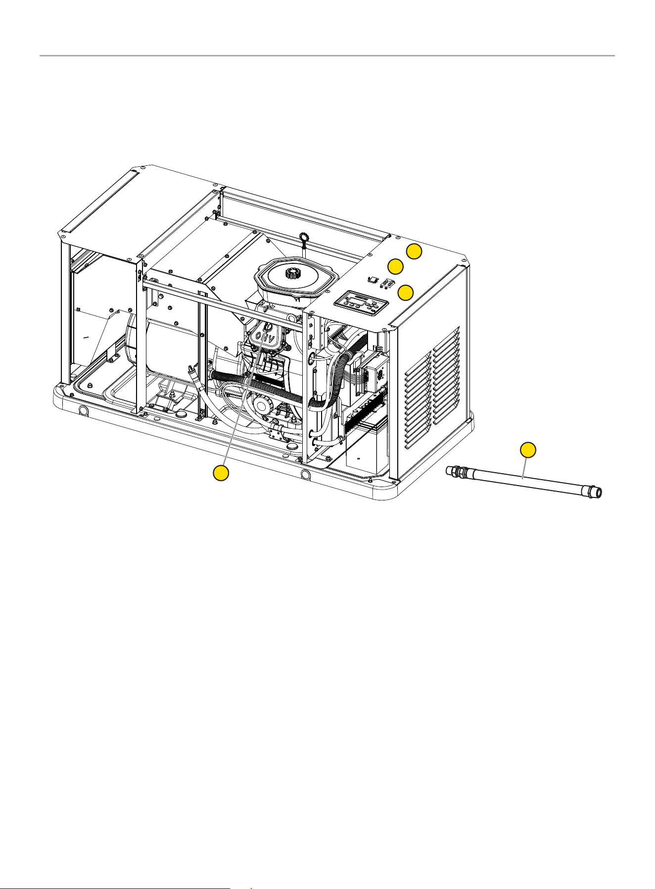
GENERAL INFORMATION
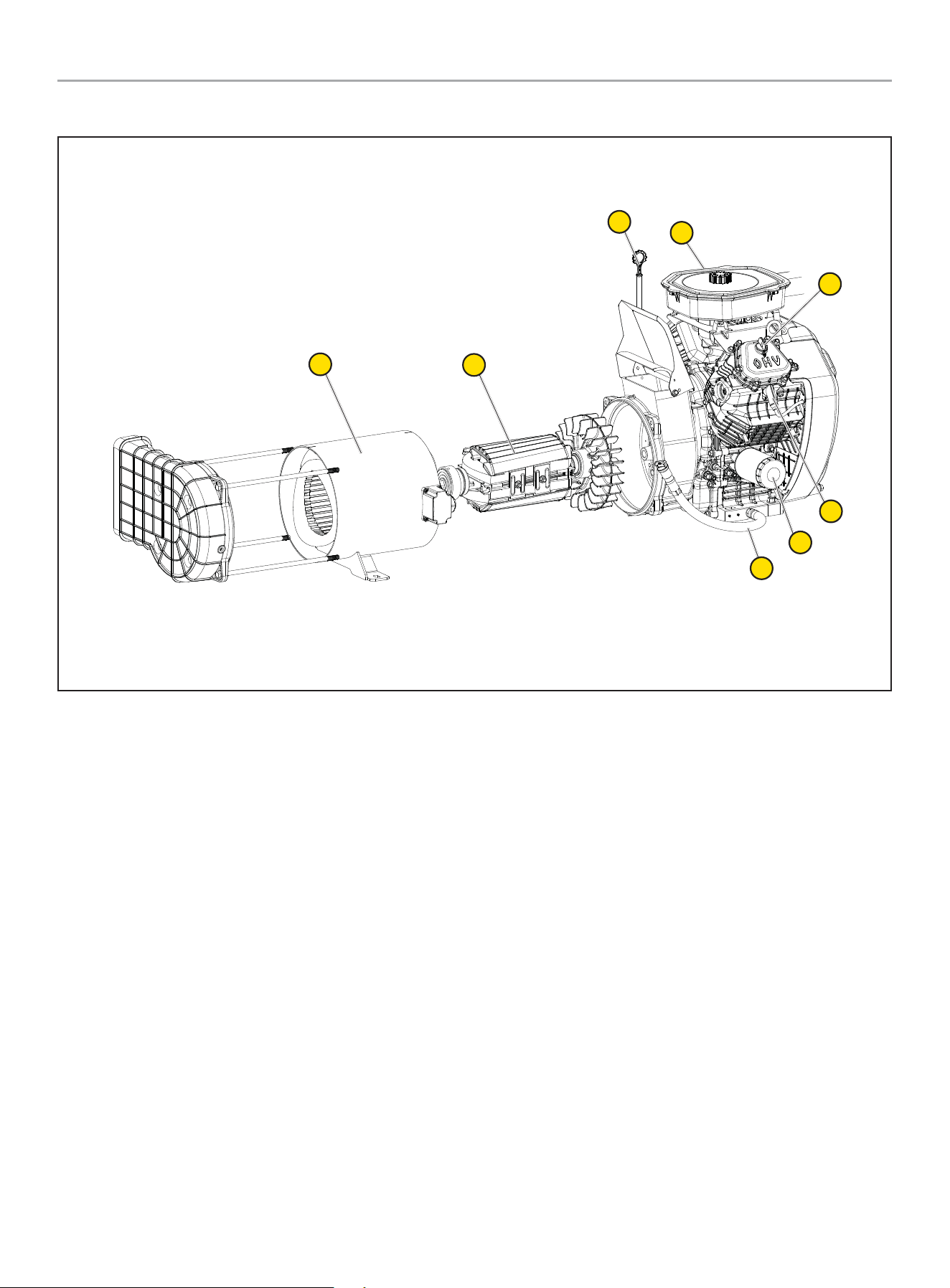
Component Identification - Home Standby (HSB) Generator
12
1
2
3
5
2
4
11
7
6
8
10
9
1. Exhaust System
2. Generator ON/OFF
3. Main Circuit Breaker
4. fleX Controller
™
5. Batteries (not included, side cover)
6. Oil Drain Hose
7. Engine
8. Alternator
9. Electric Conduit Caps
10. Exterior Warning LED
11. Fuel Inlet
12. Fuel Regulator
201202 - 22-kW HOME STANDBY GENERATOR WITH fleX CONTROLLER
™
GENERAL INFORMATION
15
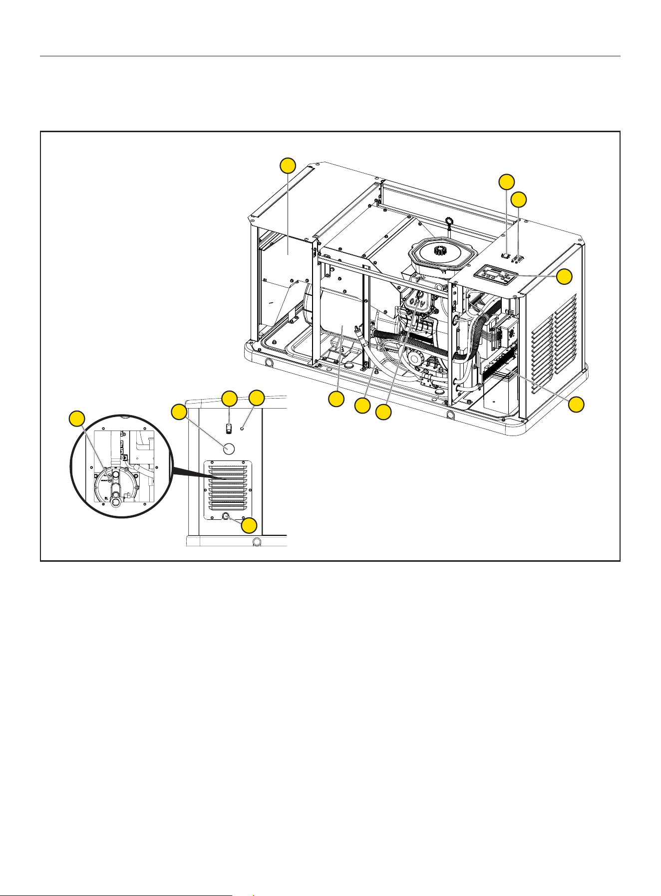
Component Identification - Engine
1
7
8
2
3
4
5
6
1. Engine Oil Dipstick
2. Air Cleaner
3. Oil Cap
4. Spark Plug (second on opposite side)
5. Oil Filter
6. Oil Drain Hose
7. Rotor Assembly
8. Stator
201202 - 22-kW HOME STANDBY GENERATOR WITH fleX CONTROLLER
™
GENERAL INFORMATION
16
Operation Symbols
Some of the following symbols may be used on this product. Please study them and learn their meaning. Proper interpretation of these
symbols will allow you to more safely operate the product.
SYMBOL MEANING
On
Off
Ground Terminal
201202 - 22-kW HOME STANDBY GENERATOR WITH fleX CONTROLLER
™
GENERAL INFORMATION
17
Control Panel
MAIN CIRCUIT BREAKER
The 100-amp main circuit breaker protects the generator from
circuit overload. The main circuit breaker controls total output of
the generator. The main circuit breaker must be in the ON position
for the fleX ATS to communicate with this standby generator.
MAIN CIRCUIT BREAKER
ON
OFF
GENERATOR ON/OFF SWITCH
NOTICE
When maintenance or service work is performed on the
generator or the home’s electrical system, to prevent
accidental startup pull out the fuse from the fleX Controller
™
panel and disconnect the batteries.
This generator has ON/OFF switches that when turned off, will
shut down the HSB (if running) and deactivate the fleX Controller
™
preventing future starts. These switches should be used in
instances where the HSB needs to stay off regardless of utility
power presence. When either switch is in the OFF position, the
HSB will not exercise or start for any reason.
When both of the switches are in the ON position, the fleX
Controller
™
will be energized and the HSB will be controlled by the
programming of the fleX Controller
™
. Both switches need to be in
the ON position in order for the HSB to operate in AUTO mode. Put
the fleX Controller
™
in AUTO mode.
OTE: N Both switches need to be in the ON position to place the
fleX Controller
™
in the AUTO mode and in order to exercise
the HSB.
Inside Back
ON
OFF
ON
OFF
FCC Statement
* Applicable in USA only.
1. This device complies with Part 15 of the FCC Rules. Operation
is subject to the following two conditions:
1a. This device may not cause harmful interference.
1b. This device must accept any interference received,
including interference that may cause undesired
operation.
2. Changes or modifications not expressly approved by the party
responsible for compliance could void the user’s authority to
operate the equipment.
NOTICE
This equipment has been tested and found to comply with
the limits for a Class B digital device, pursuant to Part 15
of the FCC Rules. These limits are designed to provide
reasonable protection against harmful interference in a
residential installation. This equipment generates, uses and
can radiate radio frequency energy and if not installed and
used in accordance with the instructions, may cause harmful
interference to radio communications.
Industry Canada: CAN ICES-002/NMB-002
* Applicable in Canada only.
This device complies with Industry Canada license - exempt RSS
standard(s).
Operation is subject to the following two conditions:
1. This device may not cause interference, and
2. This device must accept any interference, including
interference that may cause undesired operation of the
device.
Industry Canada: ICES-003/NMB-003
* Applicable in Canada only.
This device complies with Industry Canada license - exempt RSS
standard(s).
Operation is subject to the following two conditions:
1. This device may not cause interference, and
2. This device must accept any interference, including
interference that may cause undesired operation of the
device.
201202 - 22-kW HOME STANDBY GENERATOR WITH fleX CONTROLLER
™
GENERAL INFORMATION
18
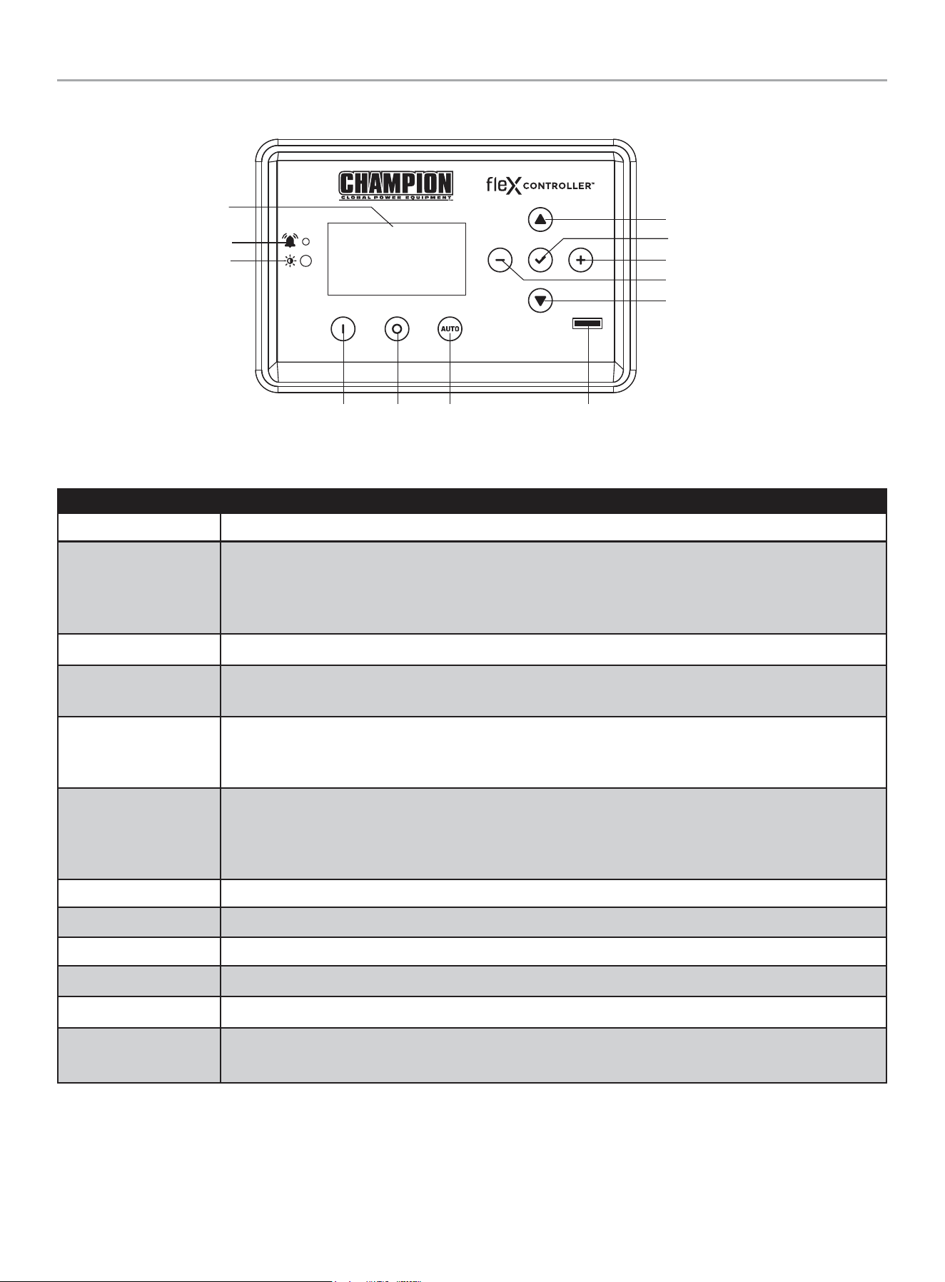
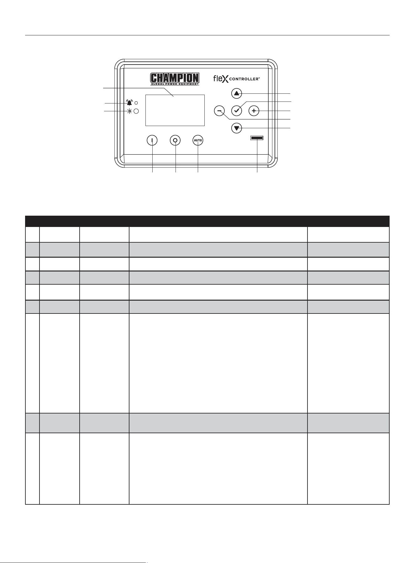
fleX Controller
™
The fleX Controller
™
provides real time monitoring, protection, information on the status and settings of the HSB.
Description
Display Shows settings and status of the HSB.
Warning
In all cases when the icon is RED, this is an indicator that the HSB has registered a fault and must be
corrected. Only the “LOW BATTERY” and “MAINTENANCE” icons will not latch out or shut down the HSB.
ALL other RED icon faults will latch out, shut down, disable starting and light the RED icon on the fleX
Controller
™
and the exterior warning LED on the backside of the HSB.
PV Photovoltaic (PV) sensor that detects environment light level and adjusts the screen brightness automatically.
Manual/ON
Press to start the HSB in Manual mode. Allows verification that the HSB power delivery circuit is functional.
The engine will start in manual mode. Safety procedures should be followed.
OFF
Press to stop the HSB in Manual or Auto mode. Closes and shuts down the engine signals. It prevents the
automatic operation of the generator. OFF is required when all maintenance or service is being performed on
or around the unit.
Auto
Press to put the HSB in Auto mode. When in Auto, this allows automatic delivery of power from the HSB
when there is a utility power outage. With the controller in the Auto and the HSB not running (standby mode),
this indicates the household is using utility power. Auto position is the standby ready position. The fleX
Controller
™
must be in the Auto mode in order to exercise.
Up/Increase Moves up in the lists of the various settings or increases variables.
Down/Decrease Moves down in the lists of the various settings or decreases variables.
Right Moves right in the lists of the various settings.
Left Moves left in the lists of the various settings.
Ok Confirms programming the fleX Controller
™
. Press and hold to enter settings pages.
Fuse
Protects the fleX Controller
™
and allow direct removal to keep the controller from engaging. Remove the fuse
while all maintenance or service is being performed on or around the unit.
Display
Warning
PV
Manual /
ON
OFF Auto
Fuse
Up/Increase
Down/Decrease
Ok
Right
Left
201202 - 22-kW HOME STANDBY GENERATOR WITH fleX CONTROLLER
™
GENERAL INFORMATION
19
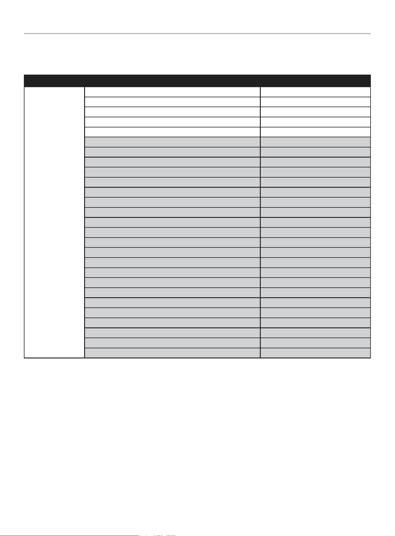
STATE
STATE variables in fleX Controller
™
. These are view-only, monitor variables.
Highlighted variables show up after the ATS is connected and powered.
TOP MENU
DESCRIPTION ON SCREEN
STATE
BATTERY VOLTAGE BATTERY VOLTS
CURRENT EVENT RUN TIME EVENT TIME
GENERATOR TOTAL HOURS TOTAL RUN TIME
VERSION VERSION
SERIAL NUMBER S/N
SYSTEM OUTPUT L1 AMPS AMPERAGE L1
SYSTEM OUTPUT L2 AMPS AMPERAGE L2
PHASE VOLTAGE (UTILITY, L1-N) UTILITY L1-N
PHASE VOLTAGE (UTILITY, L2-N) UTILITY L2-N
LINE VOLTAGE (UTILITY, L1-L2) UTILITY L1-L2
UTILITY FREQUENCY UTILITY Hz
PHASE VOLTAGE (GEN, L1-N) GENERATOR L1-N
PHASE VOLTAGE (GEN, L2-N) GENERATOR L2-N
LINE VOLTAGE (GEN, L1-L2) GENERATOR L1-L2
GENERATOR FREQUENCY GENERATOR Hz
LOAD VOLTAGE (LOAD, L1-N) LOAD L1-N
LOAD VOLTAGE (LOAD, L2-N) LOAD L2-N
LOAD VOLTAGE (LOAD, L1-L2) LOAD L1-L2
LOAD POWER (LOAD, L1-N) LOAD POWER L1-N
LOAD POWER (LOAD, L2-N) LOAD POWER L2-N
LOAD POWER (LOAD, L1-L2) LOAD POWER L1L2
LOAD1 POWER LOAD1 POWER
LOAD2 POWER LOAD2 POWER
LOAD3 POWER LOAD3 POWER
LOAD4 POWER LOAD4 POWER
AC1 POWER AC1 POWER
AC2 POWER AC2 POWER
201202 - 22-kW HOME STANDBY GENERATOR WITH fleX CONTROLLER
™
GENERAL INFORMATION
20
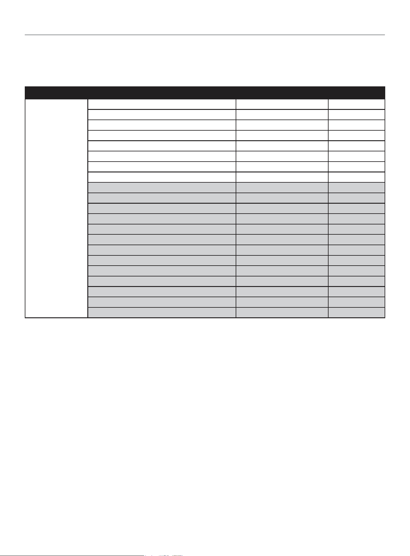
User Settings
USER variables in fleX Controller
™
.
Highlighted variables show up after the ATS is connected and powered. See Programming fleX Controller
™
for more information on
initial setup.
TOP MENU
DESCRIPTION ON SCREEN DEFAULT
USER SETTINGS
HOURS UNTIL MAINTENANCE IS REQUIRED NEXT SERVICE 100 hours
RESET SERVICE RESET SERVICE OFF
ENGINE START DELAY AFTER UTILITY LOSS BROWNOUT DELAY 30 sec.
ENGINE COOLING TIME ENG COOL TIME 60 sec.
LANGUAGE LANGUAGE English
SCREEN SLEEP TIME SLEEP DELAY 600 sec.
SCREEN BRIGHTNESS BRIGHTNESS 100%
BOND MODE BOND MODE OFF
SYSTEM TIME (year) SYS TIME (year) 2023
SYSTEM TIME (month) SYS month 12 December
SYSTEM TIME (day) SYS date 31
SYSTEM TIME (hour) SYS hour 0
SYSTEM TIME (minute) SYS minutes 0
SYSTEM TIME (second) SYS second 0
SYSTEM TIME (week) SYS week 6 Saturday
DAYLIGHT SAVINGS TIME DST OFF
EXERCISE FREQUENCY EXERCISE FREQ None
EXERCISE DAY OF WEEK EXERCISE DAY 1 Monday
EXERCISE START (hour) EXER START H 0 Midnight
EXERCISE START (minute) EXER START M 0
EXERCISE RUN TIME EXERCISE TIME 15 min.
201202 - 22-kW HOME STANDBY GENERATOR WITH fleX CONTROLLER
™
GENERAL INFORMATION
21
TOP MENU
DESCRIPTION ON SCREEN DEFAULT
ATS PARAMETERS
ATS WAITING TIME
(UTILITY TO GENERATOR TO GENERATOR)
ATS SWITCH T UG 10 sec.
ATS WAITING TIME (GENERATOR TO UTILITY) ATS SWITCH T GU 10 sec.
UTILITY OVER VOLTAGE UTIL OVER VOLT 258 V
UTILITY UNDER VOLTAGE UTIL UNDER VOLT 190 V
UTILITY OVER FREQUENCY TIME UTIL OVER FREQ 66 Hz
UTILITY UNDER FREQUENCY TIME UTIL UNDER FREQ 56 Hz
UTILITY OVER VOLTAGE TIME UTIL OVER VOL T 500 ms
UTILITY UNDER VOLTAGE TIME UTIL UND VOL T 10 sec.
UTILITY OVER FREQUENCY TIME UTIL O FREQ T 1 sec.
UTILITY UNDER FREQUENCY TIME UTIL U FREQ T 10 sec.
UTILITY LINE VOLTAGE UTIL LINE VOLT 15 V
GENERATOR OVER VOLTAGE GEN OVER VOLT 258 V
GENERATOR UNDER VOLTAGE GEN UND VOLT 190 V
GENERATOR OVER FREQUENCY GEN OVER FREQ 66 Hz
GENERATOR UNDER FREQUENCY GEN UNDER FREQ 56 Hz
GENERATOR OVER VOLTAGE TIME GEN OVER VOLT T 500 ms
GENERATOR UNDER VOLTAGE TIME GEN UND VOLT T 10 sec.
GENERATOR OVER FREQ TIME GEN O FREQ T 1 sec.
GENERATOR UNDER FREQ TIME GEN U FREQ T 10 sec.
GENERATOR LINE VOLTAGE GEN LINE VOLT 15 V
201202 - 22-kW HOME STANDBY GENERATOR WITH fleX CONTROLLER
™
GENERAL INFORMATION
22
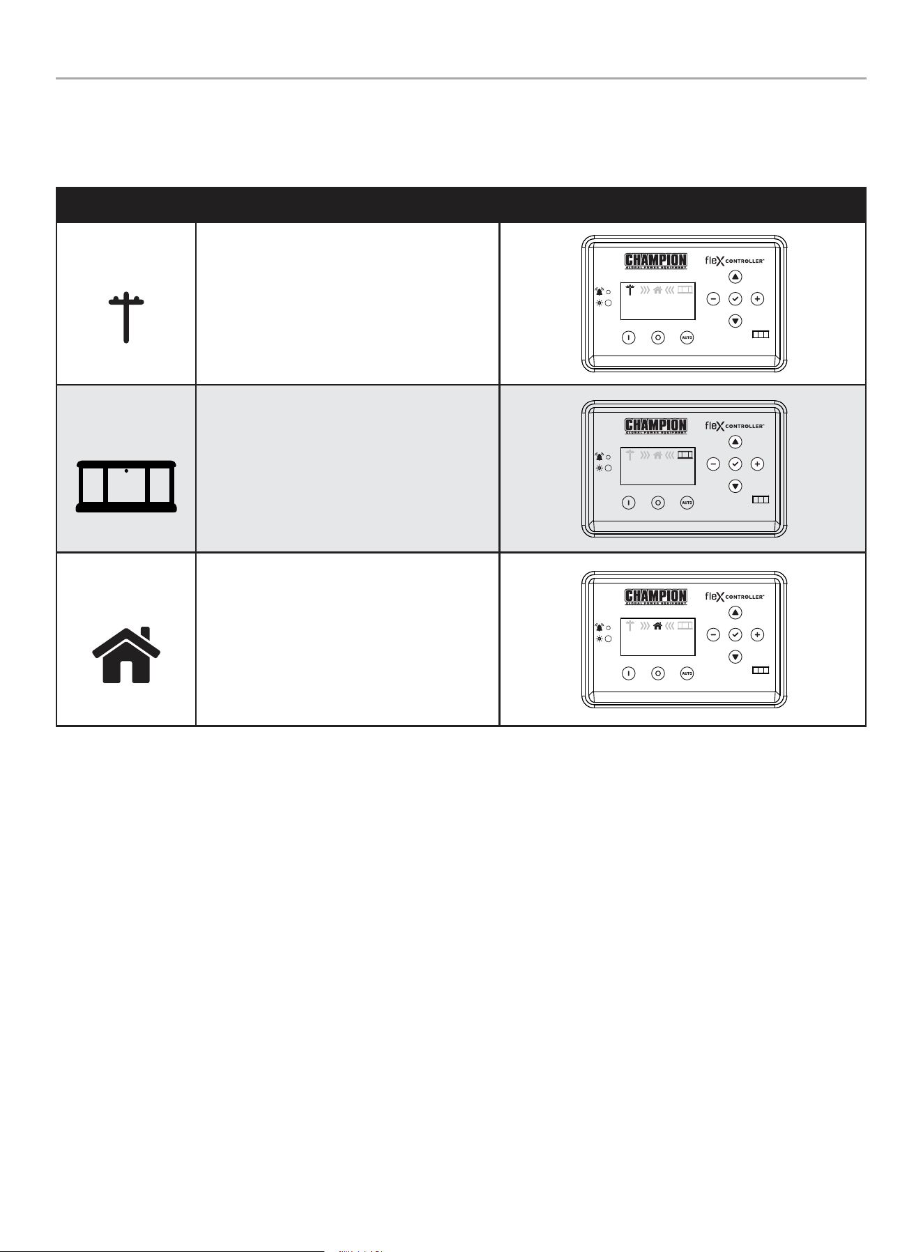
Status Icons
The fleX Controller
™
displays status icons.
Utility, HSB, House Power
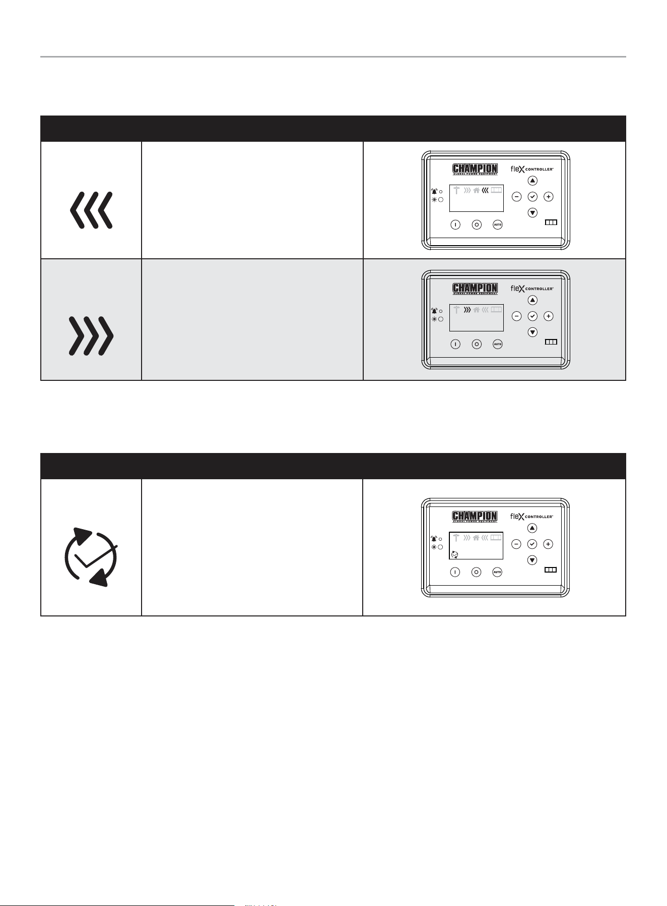
MODE DESCRIPTION
Utility
The utility pole icon indicates utility power.
AUTO
240.0V
60.0HZ
240.0V
60.0HZ
00-00
00:00
HSB
The HSB icon indicates the generator is running.
AUTO
240.0V
60.0HZ
240.0V
60.0HZ
00-00
00:00
Home
The home indicates your home is receiving power.
AUTO
240.0V
60.0HZ
240.0V
60.0HZ
00-00
00:00
201202 - 22-kW HOME STANDBY GENERATOR WITH fleX CONTROLLER
™
GENERAL INFORMATION
23
Transfer Power Direction
Show the direction of power from HSB or from utility.
MODE DESCRIPTION
HSB Supplying Power
HSB is supplying power to the home.
AUTO
240.0V
60.0HZ
240.0V
60.0HZ
00-00
00:00
Utility Supplying
Power
Utility is supplying power to the home.
AUTO
240.0V
60.0HZ
240.0V
60.0HZ
00-00
00:00
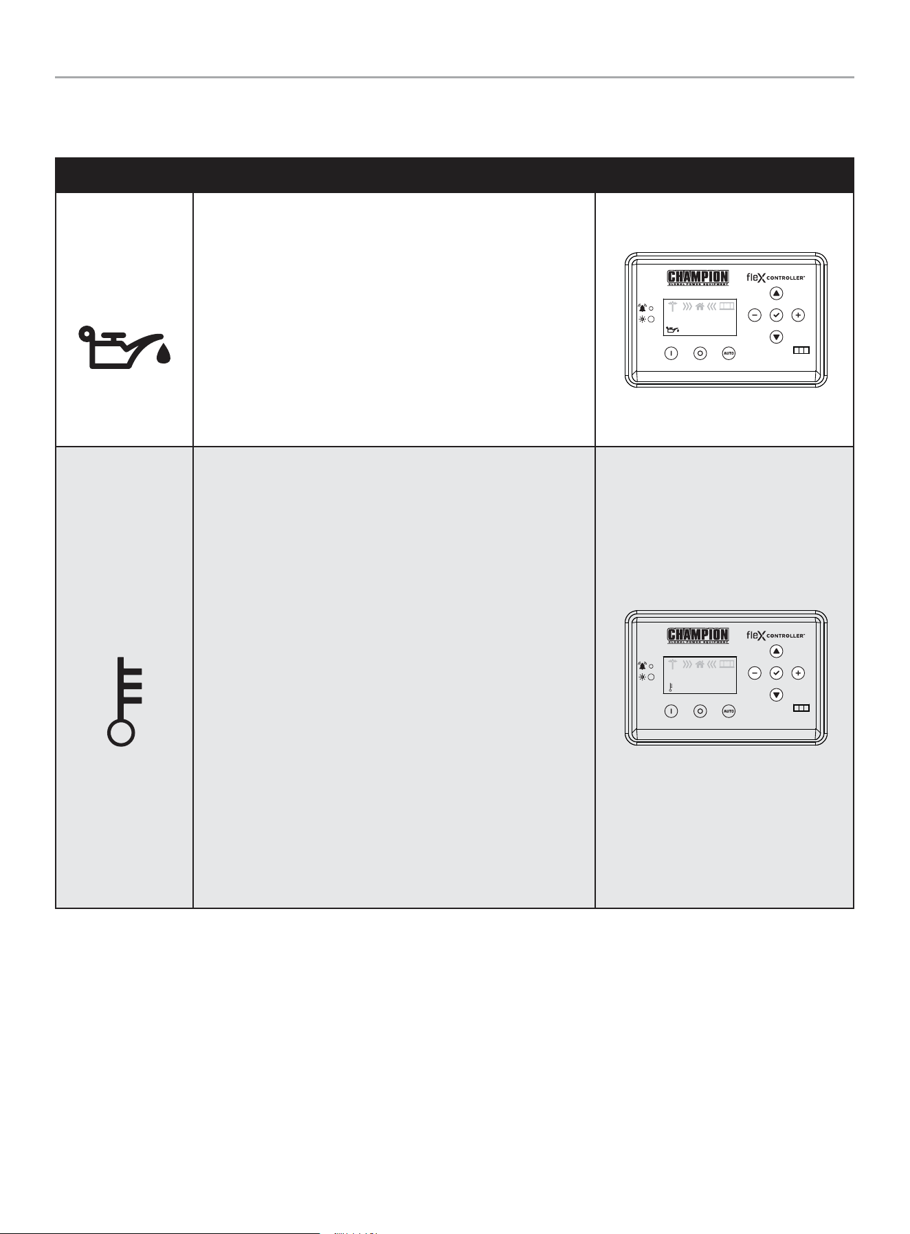
Information Icons
The fleX Controller
™
displays information icons.
MODE DESCRIPTION
Exercise
The icon indicates when the HSB is performing
the exercise period. Refer to “Setting Exercise
Time” to establish the weekly exercise period.
When the exercise period is complete the icon
will turn off and the HSB will resume its standby
monitoring. The fleX Controller
™
must be in the
AUTO mode in order to exercise.
AUTO
240.0V
60.0HZ
240.0V
60.0HZ
00-00
00:00
201202 - 22-kW HOME STANDBY GENERATOR WITH fleX CONTROLLER
™
GENERAL INFORMATION
24
Fault Icons
The fleX Controller
™
displays fault icons.
MODE DESCRIPTION
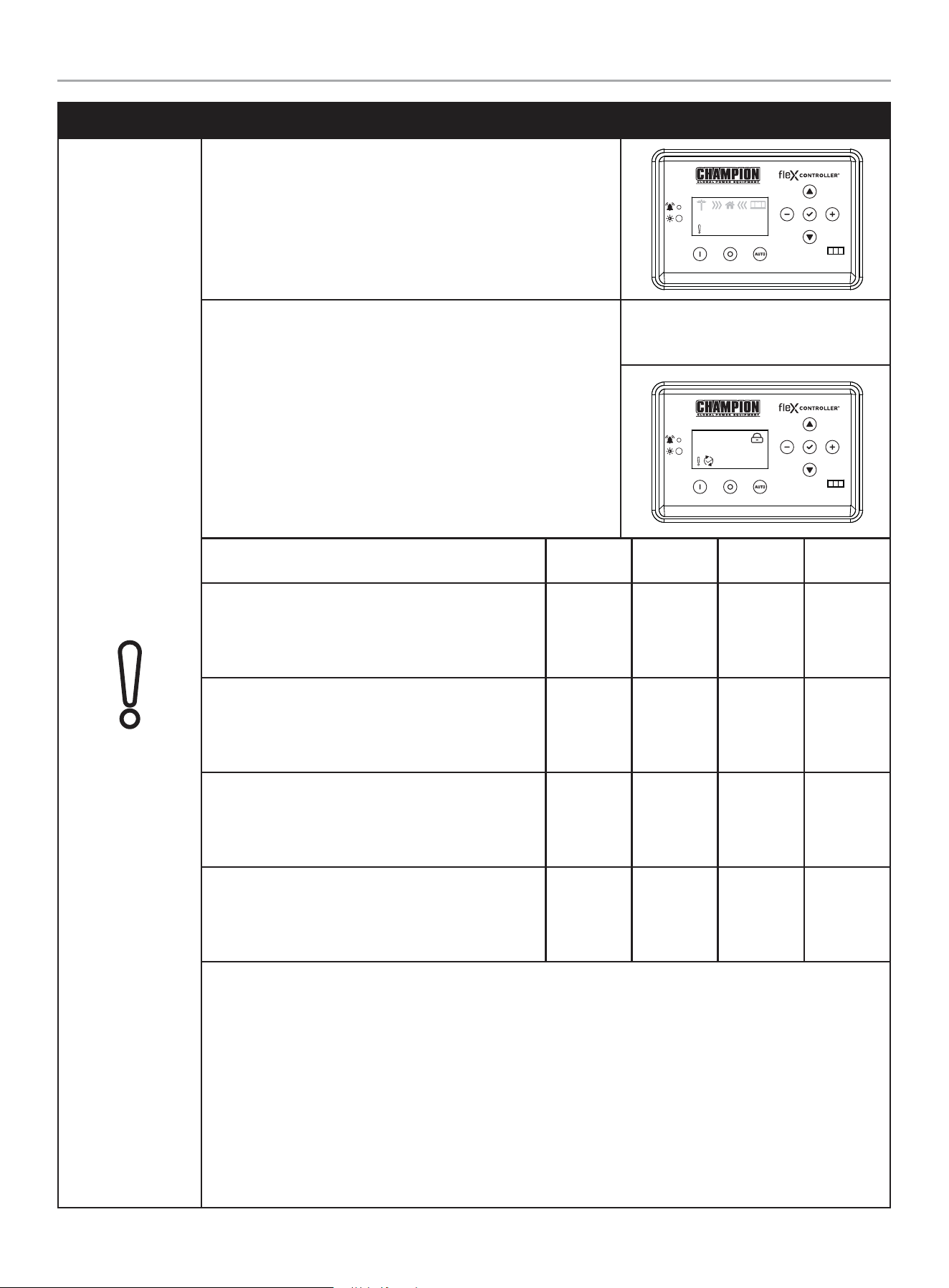
Low Oil Pressure
Shutdown
The icon will be lit when the engine oil pressure drops below a safe
operating level. When this fault is detected, the HSB will shut down
and re-start will be disabled. The warning LED on the controller and
exterior will be lit.
Check the oil level. The oil level should be at the FULL mark, if
necessary, add oil. DO NOT overfill. Inspect the unit for a possible
oil leak, if a leak is discovered, contact Champion or your nearest
Authorized Champion Dealer. Follow the FAULT CODE RESET
instructions to clear the fault after service.
AUTO
240.0V
60.0HZ
240.0V
60.0HZ
00-00
00:00
High Engine
Temperature
The icon will be lit if the engine operating temperature exceeds
the factory preset limits. If excessive operating temperature is
detected, the HSB will shut down and re-start will be disabled. The
warning LED on the controller and exterior will be lit.
This failure could be the result of an excessive load or high ambient
temperatures. Should this fault occur do the following:
1. Open the enclosure doors to increase air flow through the HSB.
2. Check oil level and add oil if required.
3. Inspect the interior and exterior of the enclosure for debris,
leaves, etc., and remove them to increase air flow around and
inside the unit.
4. Once the engine temperature falls into the normal operating
range, generally 30 minutes, follow the FAULT CODE RESET
instructions to clear the fault after service. Then, put the fleX
Controller
™
in AUTO mode.
5. Close the enclosure doors and the unit is ready to run.
AUTO
240.0V
60.0HZ
240.0V
60.0HZ
00-00
00:00
201202 - 22-kW HOME STANDBY GENERATOR WITH fleX CONTROLLER
™
GENERAL INFORMATION
25
MODE DESCRIPTION
Over Crank
The icon will be lit if the HSB does not start. This prevents the HSB
from damaging itself or other related components. When the fault is
detected, the HSB will shut down and re-start will be disabled. The
warning LED on the controller and exterior will be lit.
AUTO
240.0V
60.0HZ
240.0V
60.0HZ
00-00
00:00
STARTER CRANK CYCLE TIMES - If the HSB fails to start, the
“OVER CRANK” icon will flash on the fleX Controller® and a steady
lit exterior warning LED on the backside of the HSB. Below outlines
the crank cycle differences depending on the mode selected. Please
note there is a 120 second lockout or rest period after the cycles for
each mode listed to allow the starter to properly cool.
Follow the FAULT CODE RESET instructions by pushing the OFF
button to reset and clear the fault. Regardless of when you press
OFF, you will need to allow the timer to count down to zero (0)
before proceeding with another start procedure. The lockout time
remaining is shown on the display below the lock icon.
Example: AUTO mode, during exercise
with OVER CRANK fault. The timer upper
right is counting down 94 seconds.
AUTO
094s
Mode
ON
(seconds)
OFF
(seconds)
Cycles
Lockout
(seconds)
AUTO
The HSB is in the ready position. The fleX Controller
®
must be in the AUTO mode in order to exercise.
9 10 5 120
MAN
The HSB will start in MANUAL mode.
10 10 2 120
EXERCISE (PLC)
The HSB is connected to a Champion Automatic
Transfer Switch.
8 30 3 120
EXERCISE (2-wire)
The HSB is connected to a non-Champion Automatic
Transfer Switch.
9 10 5 120
This failure could also be the result of insufficient fuel supply. Check the in-line fuel shut off valves and make
sure they are in the ON/ OPEN position. Position them in the correct position, follow the FAULT CODE RESET
instructions to clear the fault after service.
If they are in the correct position and the HSB shows a fault light again, it’s recommended to perform a
Manometer pressure check by an Authorized Champion Dealer or installer. This will make sure the correct
amount of fuel is being delivered to the HSB when it starts.
Insufficient battery output could result in poor cranking cycles, not permitting the engine starter to reach
optimum starting RPM to start the engine. This can be verified by checking the Battery Charger icon, NO
CHARGE. If this occurs, the individual battery voltages must be checked to determine if the batteries are properly
charged or if they have failed. It is extremely important to follow all the cautions and warnings per the battery
manufacturer concerning installation, service, maintenance and replacement procedures.
201202 - 22-kW HOME STANDBY GENERATOR WITH fleX CONTROLLER
™
GENERAL INFORMATION
26
MODE DESCRIPTION
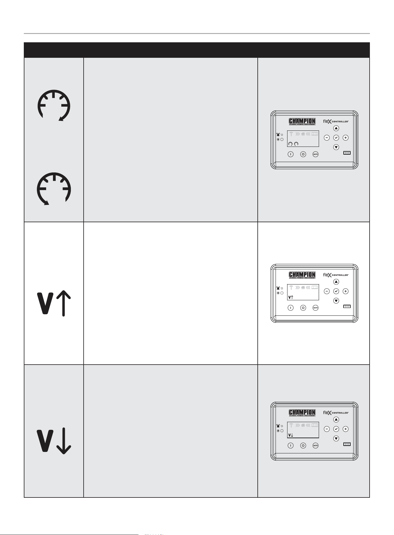
Hz Over Speed
Under Speed
The icon will be lit if the engine was operating above or below its
preset speed limits. These limits are factory set to protect the HSB
and the circuits connected to the generator output circuits. When
this fault occurs, the HSB will shut down, light the warning icon,
shut down and re-start will be disabled. The warning LED on the
controller and exterior will be lit.
When this fault occurs, the HSB will shut down, light the warning
icon, shut down and re-start will be disabled. The warning LED on
the controller and exterior will be lit.
If this failure occurs, contact Champion or your Authorized
Champion Dealer. The icon will remain lit until the failure has been
corrected, the HSB will not attempt to transfer or run. Follow the
FAULT CODE RESET instructions to clear the fault after service.
AUTO
240.0V
60.0HZ
240.0V
60.0HZ
00-00
00:00
Line Over Voltage
This icon will be lit if the HSB generator output power exceeds
preset limits of 258-290 VAC and lasts 0.5 seconds. Alternatively, if
the greater than 290 VAC and lasts 0.03 seconds. Both cases occur
if running for 6 seconds the condition occurs.
When this fault occurs, the HSB will shut down, light the warning
icon, shut down and re-start will be disabled. The warning LED on
the controller and exterior will be lit. Check and adjust AVR. Set
voltage to 240 VAC.
If this failure occurs, contact Champion or your Authorized
Champion Dealer. The icon will remain lit until the failure has been
corrected, the HSB will not attempt to transfer or run. Follow the
FAULT CODE RESET instructions to clear the fault after service.
AUTO
240.0V
60.0HZ
240.0V
60.0HZ
00-00
00:00
Line Under Voltage
This icon will be lit if the HSB generator output power is below
preset limits of 190 VAC and lasts 0.5 seconds. This will occur if
running for 5 seconds the condition occurs.
When this fault occurs, the HSB will shut down, light the warning
icon, shut down and re-start will be disabled. The warning LED on
the controller and exterior will be lit. Check and adjust AVR. Set
voltage to 240 VAC.
If this failure occurs, contact Champion or your Authorized
Champion Dealer. The icon will remain lit until the failure has been
corrected, the HSB will not attempt to transfer or run. Follow the
FAULT CODE RESET instructions to clear the fault after service.
AUTO
240.0V
60.0HZ
240.0V
60.0HZ
00-00
00:00
201202 - 22-kW HOME STANDBY GENERATOR WITH fleX CONTROLLER
™
GENERAL INFORMATION
27
MODE DESCRIPTION
Low Battery
This icon will be lit if the battery voltage falls below 21.0 volts for at
least 2 seconds while the engine is running. If the battery voltage
rises above 22 volts, the icon will turn off. Battery voltage is NOT
monitored when the engine is cranking, just when the engine is
running. If the icon comes on it will not shut the HSB off, it will
remain lit until the battery condition meets the required output.
When this fault occurs, the HSB will not shut down, light the
warning icon, the battery charging should be checked. The warning
LED on the controller and exterior will be lit.
The icon will remain lit until the failure has been corrected, the HSB
will continue to transfer or run until voltage drop causes fuel cut
solenoid to close. Follow the FAULT CODE RESET instructions to
clear the fault after service.
AUTO
240.0V
60.0HZ
240.0V
60.0HZ
00-00
00:00
Maintenance
This icon will be lit if the HSB requires maintenance.
The maintenance hour NEXT SERVICE meter counts from 100 hours
to 0. You need to reset when the hour meter reaches 0. Refer to the
scheduled maintenance chart.
The icon will remain lit until the failure has been corrected, the
HSB will continue to transfer or run. Follow the RESETTING THE
MAINTENANCE HOUR METER to clear the fault after service.
AUTO
240.0V
60.0HZ
240.0V
60.0HZ
00-00
00:00
201202 - 22-kW HOME STANDBY GENERATOR WITH fleX CONTROLLER
™
GENERAL INFORMATION
28
Fault Protection
In all cases when the icon is lit, this is an indicator that the HSB has registered a fault and must be corrected. Only the “LOW BATTERY”
and “MAINTENANCE” icons will not latch out or shut down the HSB. ALL other icon faults will latch out, shut down, disable starting and
light the icon on the fleX Controller
™
and the exterior warning LED on the backside of the HSB.
Fault Code Reset
DESCRIPTION
1 In the event a fault has occurred
OFF
ARRET
2 Push OFF button to reset
OFF
ARRET
3 Then AUTO
MAN
WARNING
All faults should be taken seriously and corrected before reset process is performed.
201202 - 22-kW HOME STANDBY GENERATOR WITH fleX CONTROLLER
™
GENERAL INFORMATION
29
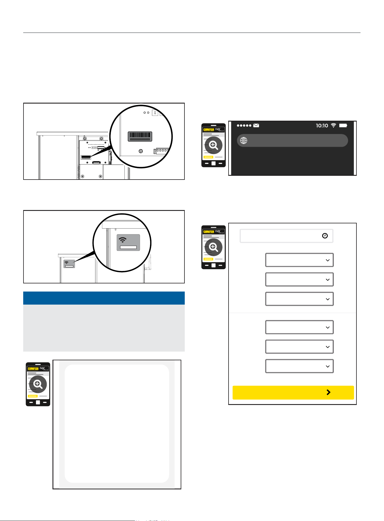
Wi-Fi Setup Method
1. Use a Wi-Fi enabled device (laptop, smart phone, tablet, etc.)
in near proximity to the ATS.
2. Search and connect to network name (SSID) “Champion
####” where #### will match the last four digits of the serial
number that is printed on the control board.
2a. The password for the network is located on a label on the
dead front of the ATS.
PASSWORD
CONTRASEÑA
MOT DE PASSE
12345678
PASSWORD
CONTRASEÑA
MOT DE PASSE
12345678
NOTICE
During the setup your device will disconnect from the internet.
The Champion Wi-Fi is a direct connection between your
device (laptop, smart phone, tablet, etc.) and the ATS, and it
does not connect to the internet. Some Android devices may
show the following screen – Choose “Connect only this time.”
Internet may not be available.
If you want to connect this network without
internet access, you can connect only this
time or you can set your phone to always
connect to it even if internet isn’t available.
You can change this in Settings >
Connections > Wi-fi > ADVANCED >
Switch to mobile data > Network
exceptions
Connect only this time
Allow switch
Stay connected
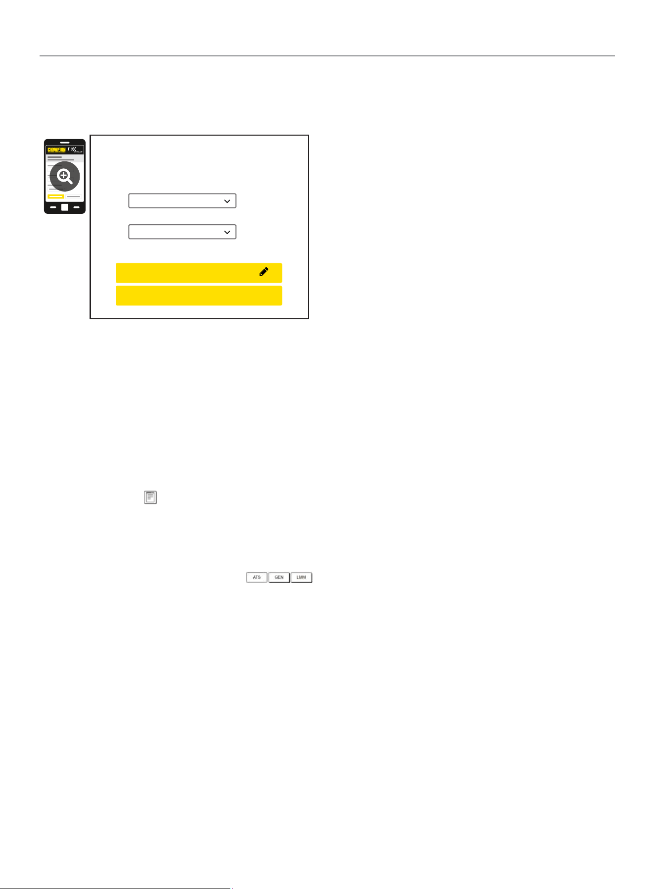
3. After connecting Wi-Fi, open your device’s web browser. In
the browser address change the address to 192.168.0.90 and
begin search. This will direct your browser to the Champion
fleX Controller
™
Home Standby Generator Settings page
located on the ATS. If your device’s web browser does not
load the Champion fleX Controller
™
Home Standby Generator
Settings Page but rather stays connected to the internet, turn
off mobile data on the device (if applicable) and make sure
the device is not connected to any other networks.
192.168.0.90
4. On the Champion fleX Controller
™
Home Standby Generator
Settings Page, set the date and time. Use either the dropdown
boxes or the “USE THIS DEVICE DATE & TIME” button to set
the time and date.
USE DEVICE DATE & TIME
Date:
Choose Month...
Choose Date...
Choose Year...
Time:
Choose Hour...
Choose Minute...
Choose AM/PM...
CONFIRM DATE & TIME
201202 - 22-kW HOME STANDBY GENERATOR WITH fleX CONTROLLER
™
GENERAL INFORMATION
30
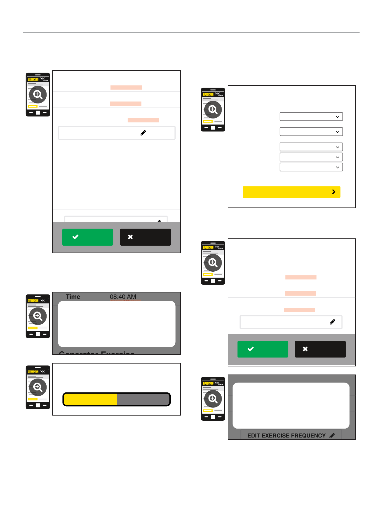
5. Confirm and apply the settings before continuing. If you do
not apply immediately, the clock will be later than actual.
Unsaved changes are highlighted.
Generator Exercise
Every Week
Friday
09:00 AM
Frequency:
Day:
Time:
March 22, 2022
08:40 AM
On
Date
Time
Day Light Saving
Generator Date and Time
EDIT DATE & TIME
(Automated Maintenance Running)
EDIT EXERCISE FREQUENCY
Unsaved Changes
Unsaved Changes
Unsaved Changes
APPLY
REVERT
6. Some operating systems will require additional steps to
confirm update, accept all pop-up windows until progress bar
is seen on screen.
Generator Exercise
Friday
09:00 AM
March 22, 2022
08:40 AM
On
Time
Day Light Saving
EDIT DATE & TIME
(Automated Maintenance Running)
Unsaved Changes
Unsaved Changes
Are your sure to save the changes?
Cancel OK
Saving...
7. Set the HSB exercise frequency and schedule.
OTE: N Exercise duration is system set at 15 minutes. The
duration is not adjustable. The fleX Controller
™
must be in
the AUTO mode in order to exercise.
Freq:
Day:
Time:
Choose Mode...
Choose Day...
Choose Hour...
Choose Minute...
Choose AM/PM...
Generator Exercise
(Automated Maintenance Running)
CONFIRM EXERCISE FREQUENCY
8. Confirm and apply the settings before continuing. Unsaved
changes are highlighted.
Every Week
Thursday
01:00 PM
Frequency
Day
Time
Unsaved Changes
Unsaved Changes
Unsaved Changes
Generator Exercise
(Automated Maintenance Running)
EDIT EXERCISE FREQUENCY
APPLY
REVERT
Every Week
Thursday
01:00 PM
Frequency
Day
Time
Unsaved Changes
Unsaved Changes
Unsaved Changes
(Automated Maintenance Running)
EDIT EXERCISE FREQUENCY
Are your sure to save the changes?
Cancel OK
201202 - 22-kW HOME STANDBY GENERATOR WITH fleX CONTROLLER
™
GENERAL INFORMATION
31
9. Wireless network settings are not used at this time. The
default values (shown below) should not be adjusted.
Adjustment of this factory settings will require a certified
electrician to correct.
Wireless Network
Internet Service:
Web Page Mode:
Direct Connect
AP Mode
CONFIRM NETWORK SETTINGS
CANCEL SETTINGS
AP Mode IP : 192. 168. 0. 90
10. The time, date, and exercise information have now been
setup for the fleX ATS and HSB. You can close your browser
and disconnect from the ATS Wi-Fi, or skip to step 2 in the
next section “ATS and HSB STATUS USING WI-FI”.
ATS and HSB Status Using WIFI
1. Using a WIFI enabled device, connect to the “Champion HSB”
WIFI network following steps 1, 2, and 3 from WIFI Setup
Method.
2. After loading the Home Standby Generator Settings page,
locate and click the icon at the bottom right corner of the
page.
3. You are now viewing the ATS and HSB status page. Items
such as voltage, frequency, current, etc. can all be viewed for
both utility and HSB power. All of the information is live. There
are three tabs located at the top of the page.
ATS, GEN, and LMM. Each tab will display the status for
the Transfer Switch, Home Standby Generator, or Load
Management Module(s) respectively.
4. When finished viewing the status of the ATS, Generator, and
LMM, close your browser and disconnect from the WIFI.
201202 - 22-kW HOME STANDBY GENERATOR WITH fleX CONTROLLER
™
GENERAL INFORMATION
32
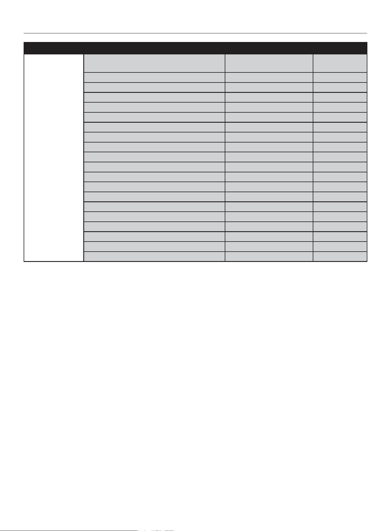
Programming fleX Controller
™
Explanation of USER SETTINGS for setting system and exercise time.
These variables show up after the ATS is connected and powered.
ON SCREEN DESCRIPTION DEFAULT VALUE
1 Year SYS year Year – each digit can be adjusted (example 2023 would be 2023) 2023
2 Month SYS month January to December with 01-12 12
3 Date SYS date Day from 1 to 31 31
4 Hour SYS hour Hours in military time 0 - 23 0
5 Minutes SYS minutes Minutes from 0-59 0
6 Second SYS second Second from 0-59 0
7 Week SYS week
Week day from 1 to 7
1= Monday
2= Tuesday
3= Wednesday
4= Thursday
5= Friday
6= Saturday
7= Sunday
6
8
Daylight
Saving Time
DST DST on “ON” or “OFF” OFF
9
Exercise
Frequency
EXERCISE
FREQ.
Exercise frequency options include:
None = no exercise
1x/MO = 1 time per month (12 times annually)
2x/MO = 2 times per month (24 times annually)
4x/MO = 4 times per month (48 times annually)
1x/WK = weekly (52 times annually)
None
Display
Warning
PV
Manual /
ON
OFF Auto
Fuse
Up/Increase
Down/Decrease
Ok
Right
Left
201202 - 22-kW HOME STANDBY GENERATOR WITH fleX CONTROLLER
™
GENERAL INFORMATION
33
ON SCREEN DESCRIPTION DEFAULT VALUE
10 Exercise Day EXERCISE DAY
Choose exercise day from 1 to 7
1= Monday
2= Tuesday
3= Wednesday
4= Thursday
5= Friday
6= Saturday
7= Sunday
1
11
Exercise
Start Hour
EXER START H Hours in military time 0 - 23 0
12
Exercise
Start
Minutes
EXER START M Minutes from 0-59 0
13
Exercise
Time
Duration
EXERCISE TIME Exercise duration from 1-100 minutes 15
201202 - 22-kW HOME STANDBY GENERATOR WITH fleX CONTROLLER
™
GENERAL INFORMATION
34
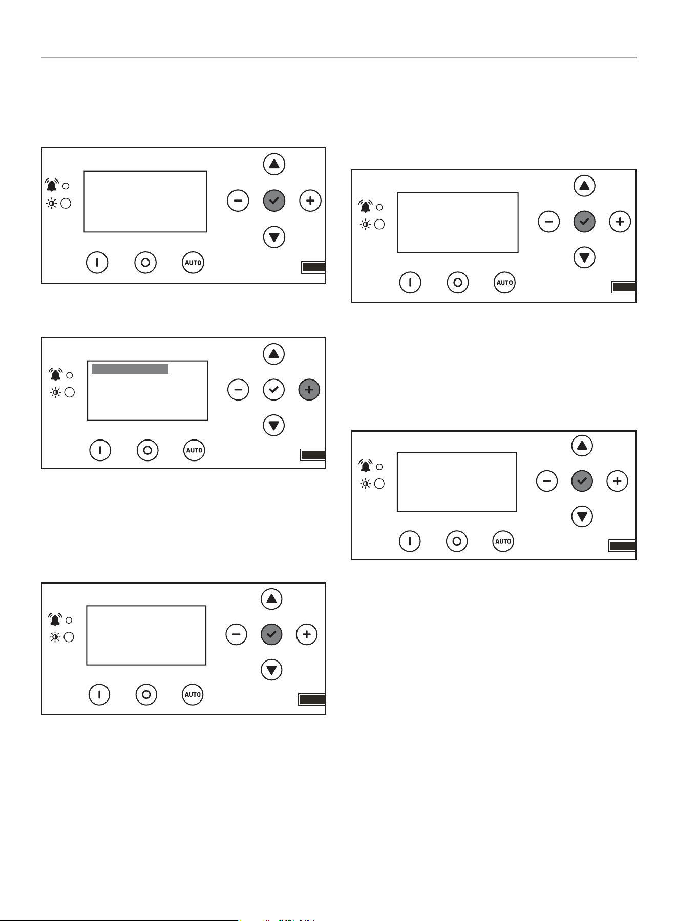
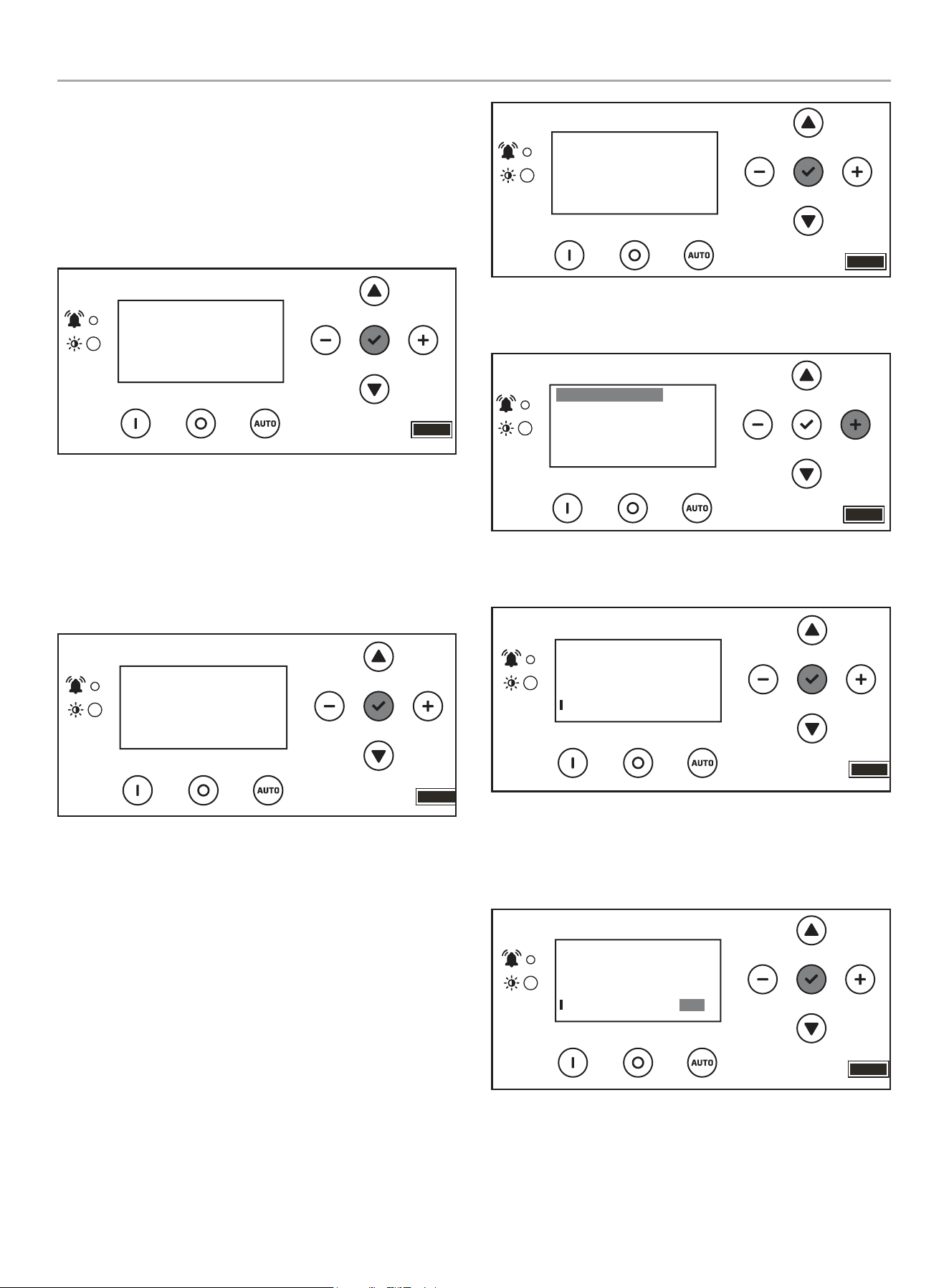
Setting System Time
1. To begin programming, disable AUTO by pressing OFF.
The screen should show OFF, then press and hold OK for 3
seconds.
OFF
00-00
00:00
ARRÊT
2. Click + until you reach USER SETTINGS. Click down once
until the first menu item is highlighted.
.USER SETTINGS
NEXT SERVICE
RESET SERVICE
BROWNOUT DELAY
100.0h
30s
OFF
3. Scroll down until you reach date settings. Press OK, on the
first setting to adjust year, then month – SYS year and SYS
month. Then use a combination of up/down to adjust each
digit of the year, then - /+ to move to the right or left and
adjust the next digit. Press OK to return and scroll down to
adjust month – SYS month - the same way.
.USER SETTINGS
BRIGHTNESS
SYS TIME (year)
SYS MONTH
100%
05
2023
4. Scroll down until you reach date settings. Press OK, on the
next setting to adjust date, hour, and minutes – SYS date,
hour, minutes. Then use a combination of up/down to adjust
each digit on the date, hour, minutes. Then - /+ to move to
the right or left and adjust each digit. Press OK to return and
scroll down to adjust second, week and DST the same way.
.USER SETTINGS
SYS date
SYS hour
SYS minutes
05
37
15
5. Scroll down until you reach date settings. Press OK, on the
next setting to adjust second, week, and daylight saving time
– SYS second, SYS week, DSI. Then use a combination of up/
down to adjust each digit on the adjust second, week, and
daylight saving time. Then - /+ to move to the right or left and
adjust each digit. DST is just ON or OFF. Press OK to return
and scroll down to adjust exercise information.
.USER SETTINGS
SYS second
SYS week
DST
52
OFF
5
201202 - 22-kW HOME STANDBY GENERATOR WITH fleX CONTROLLER
™
GENERAL INFORMATION
35
Setting Exercise Time
1. Scroll down until you reach exercise settings. Press OK, on
the next setting to adjust exercise frequency, day and start
time. Then use a combination of up/down to adjust each digit,
then - /+ to move to the right or left and adjust each digit.
Press OK to return and scroll down to adjust hour, minutes
the same way.
EXERCISE FREQ
EXERCISE DAY
EXER START H
1X/MO
12
4
.USER SETTINGS
2. Scroll down until you reach exercise settings. Press OK, on
the next setting to adjust exercise start time (the minutes
portion of the time) and length of exercise (how long the
exercise should run in minutes). Then use a combination of
up/down to adjust each digit on the adjust each digit.
Then - /+ to move to the right or left and adjust each digit.
Press OK to return.
.USER SETTINGS
EXER START M
EXERCISE TIME
20
21m
Setting Brownout Delay
Brownout allows you to adjust the settings of the fleX Controller
™
to delay start up of the HSB during a brownout or partial,
temporary reduction in system voltage or total system capacity
from your utility. Default is 30 seconds. Choose in second
increments (0-600 seconds).
1. To begin programming, disable AUTO by pressing OFF. The
screen should show OFF. Then press and hold OK for 3
seconds.
00-00
00:00
OFF
ARRÊT
2. Click + until you reach USER SETTINGS. Click down once
until the first menu item is highlighted.
.USER SETTINGS
NEXT SERVICE
RESET SERVICE
BROWNOUT DELAY
100.0h
30s
OFF
3. Scroll down until you reach BROWNOUT DELAY, and
press OK.
.USER SETTINGS
NEXT SERVICE
RESET SERVICE
BROWNOUT DELAY
100.0h
30s
OFF
4. Use a combination of up/down to adjust. Then -/+ to move to
right or left each digit brown out delay. Default is 30 seconds.
Choose in second increments (0-600 seconds). Press OK to
return.
.USER SETTINGS
NEXT SERVICE
RESET SERVICE
BROWNOUT DELAY
100.0h
OFF
30s
201202 - 22-kW HOME STANDBY GENERATOR WITH fleX CONTROLLER
™
GENERAL INFORMATION
36
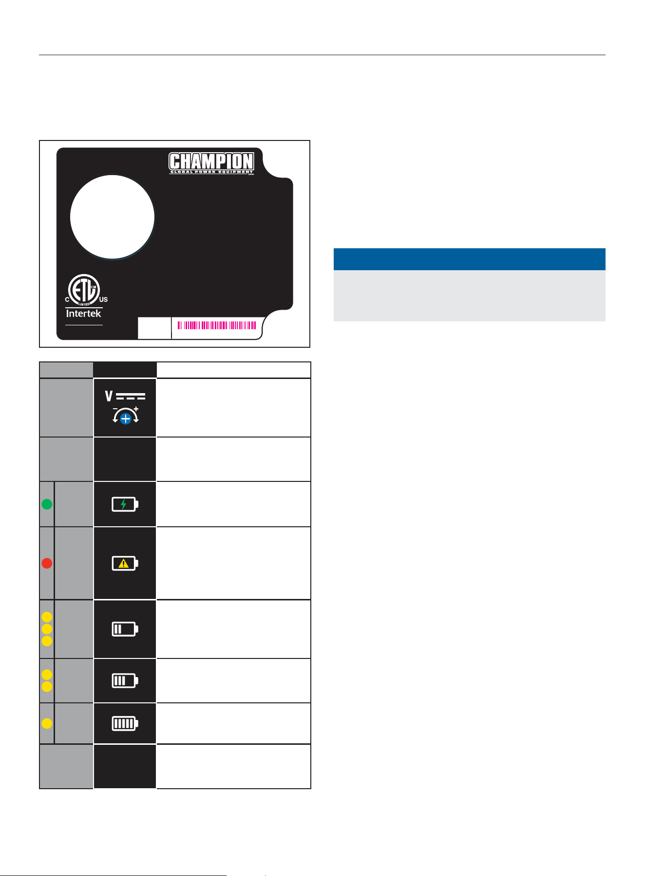
Battery Charger
The LEDs on the battery charger indicate whether the charger has
120VAC power, if there is a battery fault and the charger state.
Battery charger rating 24 VDC 7 A.
RECOGNIZED
COMPONENT
5027556
Certified to CSA Std. C22.2 NO.107.2
Conforms to UL Std.1236
4324-L-PR-B
AUTOMATIC BATTERY CHARGER
CHARGE AUTOMATIQUE DE BATTERIE
CARGADOR DE BATERÍA AUTOMÁTICO
For use with lead acid (LA/SLA), AGM, or Gel batteries.
Not for use with Lithium-ion batteries.
Pour une utilisation avec des batteries au
plomb-acide (LA / SLA), AGM ou gel.
Ne pas utiliser avec des batteries au lithium-ion.
Para uso con baterías de plomo ácido (LA/SLA), AGM o gel.
No para uso con las baterías de iones de litio.
INPUT: 80 - 125 VAC MAX 4.4 A 50/60 Hz
ENTRÉE : 80 - 125 VCA MAX 4,4 A 50 / 60 Hz
ENTRADA: 80 - 125 VCA MAX 4.4 A 50/60 Hz
OUTPUT: 24 VDC 7 A
SORTIE : 24 VCC 7 A
SALIDA: 24 VCC 7 A
SERIAL NO.
NO. DE SERIE
N° DE SÉRIE
MODEL / MODÈLE / MODELO #102652
XXXXXXXXXXXX
LED SYMBOL DESCRIPTION
DC Voltage Adjustment - Preset
from the factory for proper DC
charger output. No adjustments
necessary.
E. O.
Enforced Output - Press to charge
battery at maximum amperage for
a short period.
Green
Power - Lit to indicate the charger
is receiving 120 VAC and is ready
to charge.
Red
Fault or No Charge - Lit to indicate
a battery charging problem. If
this LED is lit, the LED on the fleX
Controller
™
, “LOW BATTERY” will
also be lit.
Yellow
High Charge - Lit to indicate the
charger is operating above 50%
capacity. Trickle charge and mid
charge LED will also be lit.
Yellow
Mid Charge - Lit to indicate the
charger is near 50% capacity.
Trickle charge LED will also be lit.
Yellow
Trickle Charge - Lit to indicate the
battery is receiving a trickle charge.
No Yellow
Low Trickle Charge - When no
yellow LEDs are lit, the charger is in
low trickle charge state.
Emission Requirements
This engine-powered generator meets all United States
Environmental Protection Agency (EPA) Phase 3 requirements and
is approved for use in both the USA and Canada.
This generator is certified to operate on pipeline NG and LPG
(vapor) fuel for use as a stationary engine for standby power
generation. Federal and/or local laws may be violated if it is used
for any other purpose.
The maintenance schedule must be followed to ensure that the
engine complies with the applicable emission standards for the
duration of the engine’s life.
NOTICE
For Emission control devices and systems, read and
understand your responsibilities for service as stated in the
Emission Control Warranty Statement of this manual.
201202 - 22-kW HOME STANDBY GENERATOR WITH fleX CONTROLLER
™
GENERAL INFORMATION
37
Specifications
Home Standby Generator
Maximum continuous power, LPG 22 kW
Maximum continuous power, NG 19.8 kW
Rated voltage 120/240
Amps 183.4/91.7 LPG (propane), 165/82.5 NG (natural gas)
Harmonic distortion Less than 5%
Main line circuit breaker 100 amp
Phase Single
Frequency 60 Hz
Unit weight 557 lbs. (253 kg) (no battery)
Size (L x W x H) 56.3 x 28 x 28.5 in. (143 x 71 x 72.5 cm)
Engine
Type OHV Commercial V-Twin
No. of cylinders 2
Displacement 999 cc
Cylinder block Aluminum with cast iron sleeves
Ignition system TCI (Transistorised Coil Ignition)
Spark plug Champion RC12YC( NGK-BKR7ES-11)
Governor Electronic
Starter Electric 24V DC
Oil capacity- Dry 3.4 US qt (3.2 L)
Oil capacity- With oil filter change 2.5 US qt (2.4 L)
Oil Type 0W-40 Full Synthetic*
RPM 3600
Controls
Mode switch auto Auto start on utility failure
Mode switch manual Starts on demand
Mode switch off Stops unit/control and charger active
Ready to run/maintenance messages Standard
Programmable start delay Standard
Engine start sequence Standard
Starter lockout Standard
Battery charger/low battery indicator Standard
Charger fault Standard
AVR over voltage protection Standard
Low oil protection Standard
Safety fused Standard
Overcrank/overspeed/underspeed protection Standard
* After 25 hours, change oil per maintenance schedule. The recommended oil type for typical use is 0W-40 full synthetic oil. However, using the listed conventional oils
shown in the “Recommended Engine Oil Type” chart may be used for typical use. If running generator in extreme temperatures, refer to the “Recommended Engine Oil
Type” chart.
201202 - 22-kW HOME STANDBY GENERATOR WITH fleX CONTROLLER
™
GENERAL INFORMATION
38
Fuel System
The engine is fitted with a dual master mixer assembly carburation
system, which allows it to run on either NG or LPG. It has been
configured at the factory to run on NG. If your installation requires
the engine to run on LPG, orifices in the master mixer assembly
carburetor must be changed.
Battery Requirements
Install two (2) 12 volt Group 51 batteries with maximum overall
dimension of 9 3/8 x 5 1/16 x 8 ¾ in. (238 x 129 x 223 mm)
L x W x H with an Automotive (A) post or terminal configuration.
Purchase batteries locally.
The required battery type for typical use is 500 CCA (Cold
Cranking Amps). However, a 435 CCA battery shown in the
Recommended Battery Type chart may be used for typical use, if
in a regularly warmer climates.
Alternatively, you may also use two (2) 12 volt Group 51R, but both
batteries must be 51R.
-40 -4 32 68 104+
Ambient temperature
Recommended Battery Type
-40
°F
°C
-20 0 20 40+
435 CCA min
500 CCA min
Install positive cable first. Install a battery series cable from the
positive (+) terminal of one battery to the negative (–) terminal of
the other battery. Always connect the positive (+) battery cable to
the generator first.
Group 51 Automotive Post Style
TO STARTER TO GROUND
BATTERY SERIES CABLE
Group 51R Automotive Post Style
TO STARTERTO GROUND
BATTERY SERIES CABLE
Group 51
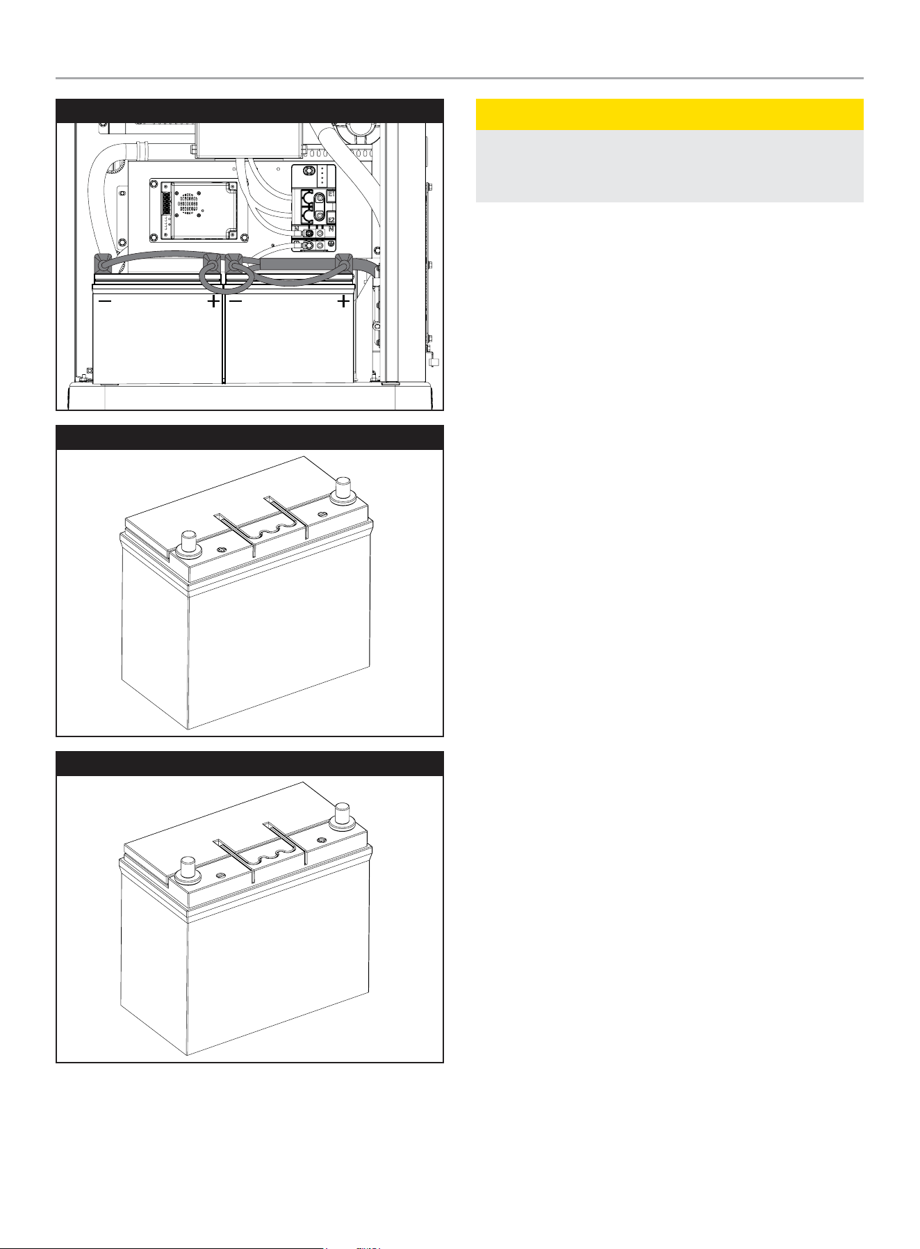
201202 - 22-kW HOME STANDBY GENERATOR WITH fleX CONTROLLER
™
GENERAL INFORMATION
39
Group 51R
Group 51
Group 51R
CAUTION
For battery installation, maintenance, and safety requirements
refer to battery manufacturer’s battery installation and safety
manual.
Battery Charging
The generator is equipped with an automatic battery charger. The
charger will sense the battery’s state of charge and automatically
charge the battery when required. LED lights on the charger
display the battery state of charge.

201202 - 22-kW HOME STANDBY GENERATOR WITH fleX CONTROLLER
™
OPERATION
40
Model and Serial Number
The model and serial number plate is affixed to the generator
above the control panel. Have this information if calling for service
or ordering parts.
STATIONARY ENGINE DRIVEN GENERATOR / STATIONNAIRE GÉNÉRATEUR ENTRAÎNÉ PAR UN MOTEUR
4423-L-PR-A
CHAMPION POWER EQUIPMENT, INC.
6370 S PIONEER WAY, UNIT 101, LAS VEGAS, NV 89113 USA / É.-U.
1-877-338-0999 • WWW.CHAMPIONPOWEREQUIPMENT.COM
5019280
CONFORMS TO
CONFORME À
ANSI / CAN / UL / ULC 2200
201202MODEL MODÈLE
120 / 240~RATED VOLTAGE - single phase TENSION NOMINALE - monophasées Volts (V)
60RATED FREQUENCY FRÉQUENCE NOMINALE Hertz (Hz)
183.4 / 91.7 (LPG / GPL)RATED CURRENT COURANT NOMINALE Amps / Ampères (A)
1.0POWER FACTOR FACTEUR DE PUISSANCE
50 %MAX LOAD UNBALANCE MAX DÉSÉQUILIBRE DE CHARGE
3600RATED ENGINE SPEED RÉGIME MOTEUR NOMINAL RPM
77-104 (25-40)RATED AMBIENT TEMPERATURE TEMPÉRATURE AMBIANTE NOMINALE °F (°C)
HINSULATION CLASS ISOLATION DE CLASSE
FLOATING / FLOTTANTNEUTRAL NEUTRE
0.0122SUBTRANSIENT IMPEDANCE IMPÉDANCE SUBTRANSITOIRE Ohms (Ω)
0.0863TRANSIENT IMPEDANCE IMPÉDANCE TRANSITOIRE Ohms (Ω)
0.5395SYNCHRONOUS IMPEDANCE IMPÉDANCE SYNCHRONE Ohms (Ω)
FOR STANDBY SERVICE POUR LE SERVICE DE SECOURS
RAINPROOF ENCLOSURE FITTED BOÎTIER ÉTANCHE À LA PLUIE ÉQUIPÉ
MADE IN CHINA
FABRIQUÉ EN CHINE
OPERATION
Before operating the generator, review SAFETY section
earlier in the operator’s manual.
High Altitude
The density of air at high altitudes is lower than at sea level.
Power derates at an elevation over sea level and ambient
temperatures over 77 °F (25 °C) are:
General power derate is 1% for every 10 °F above 77 °F. (1% for
every 5.6 °C above 25 °C).
Elevation derate is 3.5% for every 1,000 feet (304.8 m) above sea
level.
No jet change is required for LPG and NG at high elevations. The
zero-pressure regulator is self-compensating since it is balanced
to atmospheric pressure.
Enclosure and Access
Top Cover
Open the enclosure to gain access to the generator and its
components.
– Top Cover Unlock: There is a lock under the top cover
front to gain access. Insert the provided key, unlock the
cover and lift upwards.
– Top Cover Lock: Close the top cover, insert the provided
key, turn until the cover locks.
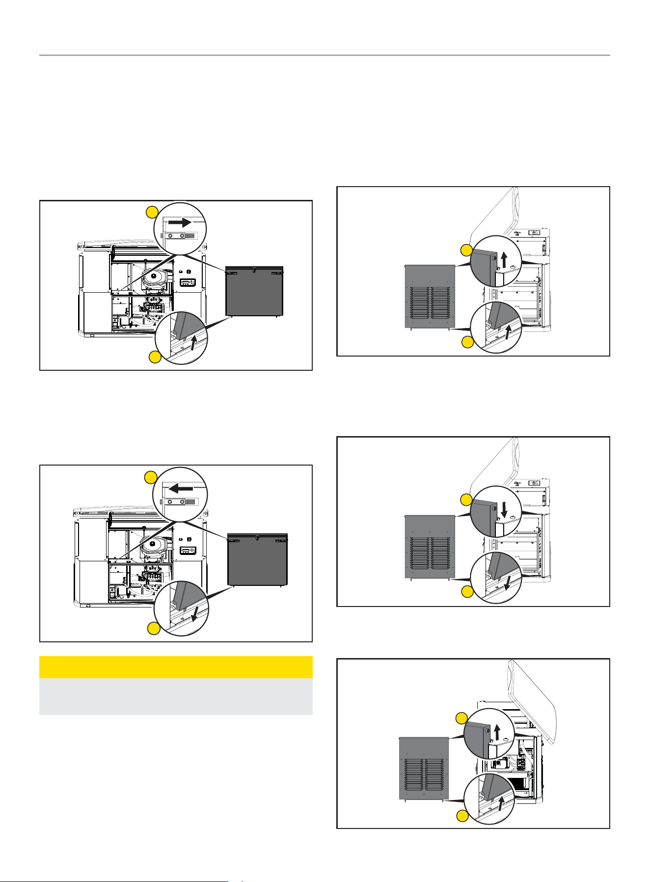
201202 - 22-kW HOME STANDBY GENERATOR WITH fleX CONTROLLER
™
OPERATION
41
Front Panel
Open the enclosure to gain access to the generator and its
components. There is a lock under the top cover front to gain
access shown earlier.
– Front Panel Removal: Open the top cover and remove
the front panel. This front panel is held position with 2
spring loaded pins on the inside. Press inward on each
side. Tilt back from the top and lift from the base.
1
2
– Front Panel Replacement: Replace the front panel by
locating the panel pins into the base, tilt the cover forward,
then press inward on each side pin. The pins are located
on the top, backside of the front panel. Lower top cover
and lock.
1
2
CAUTION
Do not close panel before moving pins inward, enclosure
damage could occur.
Side Panels
Open the enclosure to gain access to the generator and its
components. There is a lock under the top cover front to gain
access shown earlier. Left panel access muffler side, Right panel
access battery, charger, and other connections.
– Left Panel Removal: With top cover open, lift up and out
each side panel.
1
2
– Left Panel Replacement: With top cover open, replace
the side panel by locating the panel pins into the base, tilt
the cover forward, then slide down with top pins in place.
Lower top cover and lock.
1
2
– Right Panel Removal: With top cover open, lift up and
out each side panel.
1
2
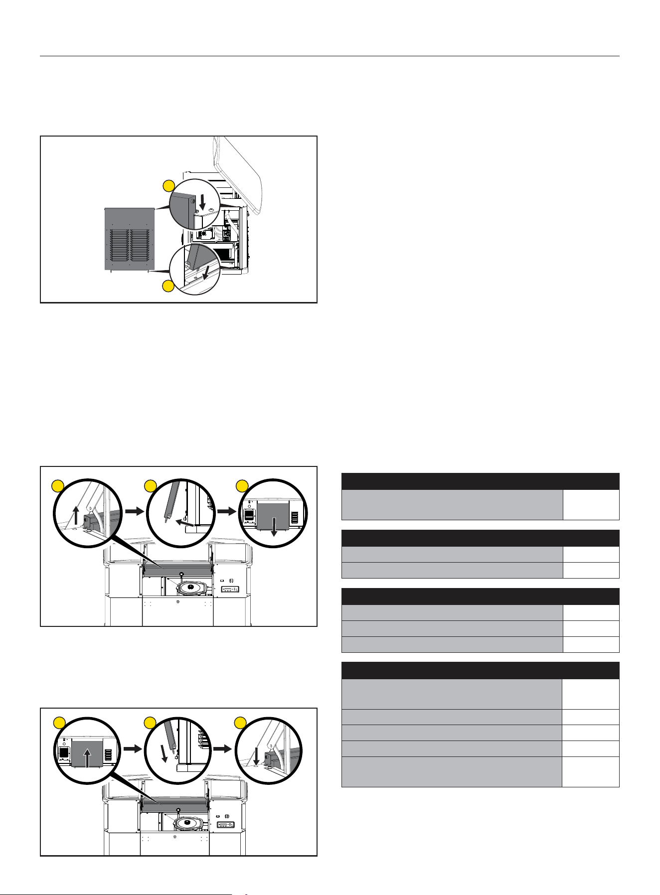
201202 - 22-kW HOME STANDBY GENERATOR WITH fleX CONTROLLER
™
MAINTENANCE
42
– Right Panel Replacement: With top cover open, replace
the side panel by locating the panel pins into the base, tilt
the cover forward, then slide down with top pins in place.
Lower top cover and lock.
1
2
Back Panel
Open the enclosure to gain access to the generator and its
components. There is a lock under the top cover front to gain
access. Unlock and lift upwards.
– Back Panel Removal: With top cover open, from the
front, lift up on the back panel, then kick out the bottom
edge towards the back once the panel pins clear. From
the back, pull the panel down and out from under the top
cover.
1
2 3
– Back Panel Replacement: With top cover open, from
the back, lift the back panel under the cover lip, and insert
the panels pins in the base. From the front, pull the panel
up, then slide the panel down with top pins in place.
1
2 3
Pre-Start Checklist
To make sure the generator is ready for proper operation, the
following items should be checked:
• Both generator ON/OFF switches in the ON position (inside
and on the back of the enclosure).
• Fuel Selector Dial is in the correct fuel position
• No fault LED is lit
• Battery is at full charge
• fleX Controller
™
is in AUTO mode
• Transfer switch is in the Utility Power position
Turning OFF the Generator
If you need to shut off the generator when it is running, put the
fleX Controller
™
in the OFF position. This will shut off the engine.
With the fleX Controller
™
in the OFF position, the generator will not
start, even if there is loss of utility power.
MAINTENANCE
Before performing maintenance procedures, review SAFETY
section starting on page 8.
Ensure that the ATS and generator ON/OFF switches are in the
OFF position before performing any maintenance or cleaning.
Scheduled Maintenance Chart
First 25Hours of Operation
Change engine oil and filter - Every 100 hours oil
and oil filter change are required
√
Weekly
Check exterior warning LED √
Inspect and clean enclosure louvers √
Monthly
Check engine oil level √*
Inspect fuel lines and connections √
Inspect and clean battery terminals √
Every 2Years or 100 Hours of Operation
Change engine oil and filter when maintenance
light comes on
√**
Inspect and clean engine air cleaner √**
Inspect engine spark plug √
Reset maintenance hour meter every 100 hours √
Complete inspection of generator, engine tune-up,
and valve lash check/adjustment
√***
* Monthly or 24 hours of continuous operation
** Service sooner if operating in high ambient temperatures or a dusty and dirty
environment.
*** Maintenance should be performed by your service dealer.
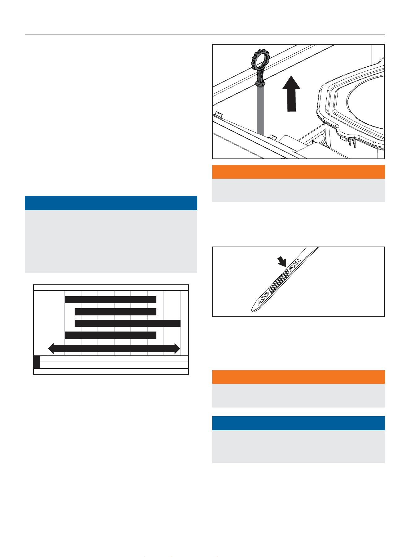
201202 - 22-kW HOME STANDBY GENERATOR WITH fleX CONTROLLER
™
MAINTENANCE
43
Spark Plug Specifications
OEM Type
.......................................Champion RC12YC
Replacement Type ...................... BKR7ES-11 or equivalent
Gap ................................. 0.024-0.031 in. (0.6-0.8 mm)
Oil Filter Specifications
OEM Type ...................................................101766
Replacement Type .................... Fram PH3600 or equivalent
Engine Oil
ENGINE OIL REQUIREMENTS
Use American Petroleum Institute (API) Service Class SN or better.
Do not use special additives.
NOTICE
The recommended oil type for typical use is 0W-40 full
synthetic oil. However, using the listed conventional oils
shown in the “Recommended Engine Oil Type” chart may be
used for typical use.
If running generator in extreme temperatures, refer to the
“Recommended Engine Oil Type” chart.
-40 -22 4 14 32
Ambient temperature
Recommended Engine Oil Type
50 86 104
-40
°F
°C
-30 -20 -10 0 10 30 40
122
50
0W-40 Full Synthetic
5W-30 Full Synthetic
10W-40
10W-30
5W-30
CHECKING THE ENGINE OIL LEVEL
Check the oil level daily when the generator is running for an
extended period of time.
1. If the generator is running during a utility outage, turn off all
household loads.
2. Put the fleX Controller
™
in the OFF position.
3. Remove the dipstick. Wipe it dry with a clean cloth and
completely reinsert it into the dipstick tube.
WARNING
DO NOT overfill the engine with engine oil. Damage to the
engine may occur.
4. Install the dipstick.
5. Remove the dipstick. The oil level should be at the FULL
mark. If necessary, add oil. DO NOT overfill.
6. Put the fleX Controller
™
to the previous position (either
Manual/ON, OFF or AUTO for example).
Changing the Engine Oil
WARNING
Always wear protective glasses or goggles and protective
clothing when changing hot engine oil.
NOTICE
Always be environmentally responsible. Consult local
authorities or reclamations facility for proper disposal of
engine oil waste.
1. Press the Manual/ON button on the fleX Controller
™
to start
and run the HSB.
2. Allow the engine to run until it reaches operating temperature.
3. Put the fleX Controller
™
in the OFF position.
4. Remove the fuse from the front of the fleX Controller
™
. This
will disable automatic starting in the event of a power outage.
201202 - 22-kW HOME STANDBY GENERATOR WITH fleX CONTROLLER
™
MAINTENANCE
44
5. Put the generator ON/OFF switch to the OFF position.
6. Open the top cover and remove the front panel. This front
panel is held position with 2 spring loaded pins on the inside.
Press inward on each side. Tilt outward from the top and lift
up from the base.
7. Remove oil drain hose (A) from oil hose clamp (B).
A
B
A. Oil Drain Hose B. Oil Drain Clamp
8. Position hose over a suitable drain pan (A). Unscrew oil drain
hose cap (B) from oil drain hose (C).
C
A
B
A. Oil Drain Pan B. Oil Drain Hose
Cap
C. Oil Drain Hose
9. Allow crankcase to empty.
10. After the oil is drained, reinstall the oil drain hose cap by
screwing it back on snugly, making sure o-ring is in place.
Reclip the oil drain hose back on the oil hose clamp that was
holding it.
11. Using a funnel, fill the engine with the proper amount of
engine oil. DO NOT OVERFILL.
12. Replace the front panel by locating the panel pins into the
base, tilt the cover forward, then press inward on each side
pin. The pins are located on the top, backside of the front
panel.
13. Reinstall fuse removed in the earlier step.
14. Turn the generator ON/OFF switch to the ON position.
15. Put the fleX Controller
™
to the previous position (either
MANUAL or AUTO for example).
201202 - 22-kW HOME STANDBY GENERATOR WITH fleX CONTROLLER
™
MAINTENANCE
45
Inspect and Clean Engine Air Cleaner
1. Press the OFF button on the fleX Controller
™
.
2. Put the generator ON/OFF switch in the OFF position.
3. Remove the fuse from the front of the fleX Controller
™
. This
will disable automatic starting in the event of a power outage.
4. Open the top cover to gain access to the air filter.
5. Unscrew the air filter screw cap holding the air cleaner cover
in place and remove the air cleaner cover. Check the air
cleaner gasket is in good shape, if not replace the gasket.
6. Remove the air cleaner paper element to inspect.
A
B
C
D
A. Air filter screw cap B. Air cleaner cover
C. Paper element/foam filter D. Air Cleaner Base
7. Remove the paper element/foam filter (C) and inspect the
paper element for any rips or tears. Replace it if damaged.
8. Hold the paper element up to a light. You should be able
to see light through the paper element, if not replace the
element. Inspect the air cleaner foam element, air cleaner
cover and base, remove any dirt or debris.
9. Install paper element plus air cleaner foam element as one
piece back in the air cleaner base.
10. Reinstall the air paper element/foam filter.
11. Replace air filter cover and screw the air filter screw cap
holding the air cleaner cover on.
12. Put the fleX Controller™ to the previous position (either
Manual/ON, OFF or AUTO for example).
Spark Plug
1. Press the OFF button on the fleX Controller
™
.
2. Remove the fuse from the front of the fleX Controller
™
. This
will disable automatic starting in the event of a power outage.
3. Put the generator ON/OFF switches in the OFF position.
4. Remove the spark plug cable from the spark plug.
5. Clean the area around the spark plug to keep dirt out of the
engine and remove the spark plug.
6. Inspect the spark plug electrode and replace the plug if the
electrode shows signs of deterioration.
7. Check the gap before installing the spark plug. The spark
plug gap should be 0.024 – 0.031 in. (0.6 – 0.8 mm).
0.024 - 0.031 in.
(0.6 - 0.8 mm)
8. Carefully thread the spark plug into the engine and tighten to
20-30 N-m (14.8-22.1 lbf-ft).
9. Re-connect the spark plug cable.
10. Reinstall fuse removed in the earlier step.
11. Put the generator ON/OFF switch to the ON position.
12. Put the fleX Controller
™
to the previous position (either
Manual/ON, OFF or AUTO for example).
201202 - 22-kW HOME STANDBY GENERATOR WITH fleX CONTROLLER
™
MAINTENANCE
46
Battery Maintenance
1. Press the OFF button on the fleX Controller
™
2. Remove the fuse from the front of the fleX Controller
™
. This
will disable automatic starting in the event of a power outage.
3. Put the generator ON/OFF switches in the OFF position.
4. Inspect the battery cables and terminals for corrosion.
5. Check that the cables are securely fastened to the terminals.
6. Check the ground lug and make sure the connections are
tight.
7. Check the fluid level of the battery, unless sealed. If low, top
off the level using distilled water only.
Follow all battery instructions provided by the battery
manufacturer.
Resetting the Maintenance Hour Meter
The maintenance hour meter counts down 100 hours. Once
completed the 100-hour maintenance, refer to below to reset the
hour meter.
Refer to the scheduled maintenance chart for specific
maintenance.
1. Press up to change reset service to ON.
.USER SETTINGS
NEXT SERVICE
RESET SERVICE
BROWNOUT DELAY
100.0h
30s
ON
2. Press ok to save the Settings.
.USER SETTINGS
NEXT SERVICE
RESET SERVICE
BROWNOUT DELAY
100.0h
30s
ON
Corrosion Protection
NOTICE
Never use a pressure washer to wash the interior of the
generator with water.
Wash the outside of the enclosure using a mild soap and water.
Use an automotive-type wax and wax the outside of the enclosure
to protect it from the elements. If used in a salt water/coastal
area, the enclosure should be washed more frequently to prevent
corrosion. Spray light oil on the hinges for the enclosure doors.
Maintenance After Submersion
WARNING
Never try to start or operate the generator if it has been
submerged underwater or exposed to a flood.
If the generator has been in conditions where it became
submerged underwater, the generator must be inspected and
maintenance must be performed before returning the generator to
service.
Put the fleX Controller
™
in the OFF position. Remove the fuse
from the front of the fleX Controller
™
. This will disable automatic
starting in the event of a power outage. Put the generator ON/
OFF switches and ATS in the OFF position. Have a authorized
Champion Dealer inspect the generator and perform any
necessary maintenance.
If the house or building has been exposed to a flood, it should be
inspected by a certified electrician for any electrical problems
that may occur if the generator is put back into service or if utility
power is restored.
201202 - 22-kW HOME STANDBY GENERATOR WITH fleX CONTROLLER
™
TROUBLESHOOTING HSB
47
TROUBLESHOOTING HSB
Engine will not crank/turn over
1 HSB set in OFF mode. Place the fleX Controller
™
in the AUTO position.
2 Battery not connected or loose, corroded posts or wires
Connect the batteries according to operator’s manual, clean and
tighten the battery connections
3 Battery(s) not charged or low charge. Recharge or replace battery(s).
4 Check for active fault code. Identify fault code, correct and reset.
5 Defective starter solenoid *
6 Defective starter *
7 Either generator ON/OFF switch is in the OFF position.
Check both switches are in the ON position (inside and on the back of
the enclosure).
Generator will crank/turn over but will not start
1 Check for active fault code. Identify fault code, correct and reset.
2 Fuel valve(s) turned off. Turn on fuel supply.
3 Fuel pressure insufficient*. Manometer check, confirm fuel pressure to fuel regulator*.
4 Weak battery(s). Recharge or replace battery(s)
5 Low oil level. Check for oil leaks. Check the oil level and add oil if necessary.
6 Spark plug wire is disconnected. Connect spark plug wire.
7 Defective fuel solenoid/regulator. *
Engine starts, runs rough
1 Fuel pressure insufficient*. Manometer check, confirm fuel pressure to fuel regulator*.
2 Wrong fuel. Check Fuel Selector Dial is in the correct position.
3 Incorrect Fuel Selector Dial position. Incorrect fuel selected, rotate Fuel Selector Dial to correct fuel.
4 Plugged air cleaner Clean or replace air cleaner.
5 Generator overloaded*. Remove one or more loads*.
6 Shorted circuit *
201202 - 22-kW HOME STANDBY GENERATOR WITH fleX CONTROLLER
™
TROUBLESHOOTING HSB
48
HSB starts, then suddenly stops
1 Check for active fault code. Identify fault code, correct and reset.
2 Fuel supply insufficient* Manometer check, confirm fuel pressure to fuel regulator*.
3 Low oil pressure shut down. Check for oil leaks. Check the oil level and add oil if necessary.
4 Generator over loaded.
Turn off standby circuits for house, reset fault, place unit back into
AUTO mode. Turn on standby circuits for house. If problem returns
contact Champion or Champion service dealer*.
5 Engine high/over temperature shut down.
Check all intake and exhaust ventilation around the HSB, remove all
debris. Let HSB sit for 30 minutes to cool down.
No AC output
1 Circuit breaker in “OFF” position Turn on breaker.
2 Main circuit breaker in “OFF” position. Turn on breaker.
3 Transfer switch breaker in “OFF” position. Turn on breaker.
4 Standby breakers set in “OFF” position. Turn on breaker.
5 Line circuit tripping breaker because of short circuit *
6 Line circuit tripping breaker because of overload *
7 Poor wiring connections*
8 ATS problems*
Reset fault code(s)
There is an exterior warning LED located on the back of the enclosure. This should be checked weekly to make sure there are no active
fault codes.
Maintenance
1
The maintenance hour meter counts from 100 hours to 0.
You need to reset when the hour meter reaches 0.
Refer to “Resetting the maintenance hour meter” for instructions after
performing maintenance.
BATTERY(S) NO OR LOW LEVEL CHARGED, BATTERY(S) DEAD, NEEDS REPLACEMENT, THE EXERCISE TIME MUST BE RESET ONCE
THE BATTERY(S) HAVE BEEN DISCONNECTED.
* *Contact Champion Power Equipment, Technical Service toll free 1-877-338-0999, tech@championpowerequipment.com or your nearest Champion dealer.
www.championpowerequipment.com

201202 - 22-kW HOME STANDBY GENERATOR WITH fleX CONTROLLER
™
ADDITIONAL INFORMATION
49
ADDITIONAL INFORMATION
Surge Protection
CAUTION
Voltage fluctuation may impair the proper functioning of
sensitive electronic equipment.
Electronic devices, including computers and many programmable
appliances use components that are designed to operate within a
narrow voltage range and may be affected by momentary voltage
fluctuations. While there is no way to prevent voltage fluctuations,
you can take steps to protect sensitive electronic equipment.
1. Install UL1449, CSA-listed, plug-in surge suppressors
on the outlets feeding your sensitive equipment. Surge
suppressors come in single or multi-outlet styles. They’re
designed to protect against virtually all short-duration voltage
fluctuations.
Customer Familiarization Summary
It’s important to educate the home owner on proper maintenance,
operation and service call procedures. A properly educated home
owner can reduce unnecessary service trips and phone calls.
Ensure that the installation of the HSB and ATS has been correctly
performed as outlined by the manufacturer and that it meets all
applicable codes.
Test and confirm proper operation of the HSB and ATS system as
outlined in the appropriate installation and operator’s manuals.
Educate the home owner on the location and operation of;
• Full flow shutoff valve
• Automatic operation of the HSB system
• Battery Charger and LED indicators
• Exterior warning LED on the backside of the HSB
• ATS operation
• Exercise scheduled time of operation
• Scheduled Maintenance
• Fill out and provide the customer a copy of the HSB,
ATS model & serial number reference. This information
is extremely important for part purchases and service
information, these numbers are specific to each HSB
and ATS.
• Fill out and provide the customer a copy of the ATS
back-up circuits.
• Fill out the Circuit Label inside the ATS.
It’s always a good business practice to place business cards in the
Operator’s and Installation manuals and place dealer stickers on
the HSB and ATS for the customer’s reference.

201202 - 22-kW HOME STANDBY GENERATOR WITH fleX CONTROLLER
™
ADDITIONAL INFORMATION
50
HSB, ATS Model & Serial Reference ATS Back-up Circuits
HSB Model Number
HSB Serial Number
Fuel Type LPG NG
ATS Model Number
ATS Serial Number
ATS circuits powered
Date Installed
Dealer/Installer
Address
Phone
Cell
Purchased from

201202 - 22-kW HOME STANDBY GENERATOR WITH fleX CONTROLLER
™
GENERAL INFORMATION
51
Maintenance and Service Record
Keeping accurate records when any service is preformed is important. Records replace guessing when a repair was done or when it should
be scheduled. Hour Meter notation as well as the date provides better time period records. To maintain the overall performance throughout
the life of the product follow the scheduled maintenance chart contained in your operator’s manual or refer to
www.championpowerequipment.com. Genuine Champion parts must be used to ensure warranty coverage.
Date
Hour Meter
Service Preformed
Record the name, address and phone number of your authorized Champion dealer

10 YEAR LIMITED WARRANTY*
Basic Warranty Provisions
Champion Air-Cooled 8.5kW – 22kW Home
Standby Units USA and Canadian Models
For a period of 10 years or 2000 hours (whichever occurs first)
from successful activation by an Authorized Champion Home
Standby Dealer, Champion Power Equipment will, at its option,
repair or replace any part(s) which upon examination, inspection
and testing by Champion Power Equipment or an Authorized
Champion Home Standby Dealer is found to be defective under
normal use and service, in accordance with the Warranty
Schedule set forth below.
Any equipment that the purchaser/owner claims to be defective
must be examined by the nearest Authorized/Certified Champion
Home Standby Service Dealer. This warranty applies only to
Champion Power Equipment automatic standby generators used
in “Standby” applications as Champion has defined Standby.
Scheduled Maintenance, as outlined by the generator owner’s
manual is required. This Scheduled Maintenance should be
performed by a knowledgeable, experience operator or an
Authorized/Certified Champion Home Standby Service Dealer.
WARRANTY SCHEDULE
Years 1 and 2 – Limited comprehensive coverage on mileage,
labor and parts
Years 3 through 10 – Limited comprehensive coverage on
parts only
GUIDELINES:
– Warranty begins upon the successful activation of the unit.
– Unit should be Registered and Proof of Purchase and
Maintenance must be available.
– Warranty is transferable between ownership of original
installation site.
– Warranty only applies to permanently wired and mounted
units.
– Any and all warranty repairs and/or concerns must be
performed and/or addressed by an Authorized/Certified
Champion Home Standby Service Dealer. Repairs or
diagnostics performed by individuals other than Authorized/
Certified Champion Home Standby Service Dealers not
authorized in writing by Champion Power Equipment will not be
covered.
– A Champion approved Transfer Switch is highly recommended
to be used in conjunction with the generator set. The
Champion Transfer Switch is covered under its own, separate
warranty listed in the Transfer Switch Instruction Manual and
is not covered under this warranty schedule.
– If a Non-Champion approved Transfer Switch is substituted
for use and directly causes damage to the generator set, no
warranty coverage shall apply.
– Steel enclosures are warranted against rusting for the first
year of ownership only. Damage caused after receipt of
generator is the responsibility of the owner and is not covered
by this warranty. Nicks, scrapes, dents or scratches to the
painted enclosure should be repaired promptly by the owner.
– All warranty expense allowances are subject to the conditions
defined in Champion Power Equipment “Home Standby”
Warranty Policy and Procedures Manual.
THIS WARRANTY SHALL NOT APPLY TO THE
FOLLOWING:
– Original installation or start-up costs
– Champion Home Standby generators that utilize non-Champion
Power Equipment replacement parts
– Costs of normal maintenance (i.e. tune-ups, associated part(s),
adjustments, loose/leaking clamps, installation and start-up)
– Units sold, rated or used for “Prime Power”, “Trailer Mounted”
or “Rental Unit” applications
– Damage to generator system (including transfer switch)
caused by improper installation or costs necessary to correct
installation
– Units used for Prime Power in place of existing utility power
(where utility power is present) or in place of utility power
where utility power service does not normally exist. Prime
power includes any application that does not use the utility
grid for electric power (example: Solar power)
– Fuel connections other than conventional utility company
supplied natural gas systems or conventional LP vapor
withdrawal systems
– Any failure caused by contaminated fuels, oils or lack of proper
fuels, oils or failure to perform scheduled maintenance and
service the air filter
– Steel enclosures that are rusting due to the improper
installation, location in a harsh or saltwater environment or
scratched where integrity of paint applied is compromised
– Failures due, but not limited, to normal wear and tear,
accident, misuse, abuse, negligence or improper installation.
As with all mechanical devices, the Champion engines need
periodic part(s) service and fluid replacement to perform as
designed.
– Failures caused by any external cause or act of God, such as
collision, theft, vandalism, riot or wars, nuclear holocaust,
fire, freezing, lightning, earthquake, windstorm, hail, volcanic
eruption, water or flood, tornado or hurricane
– Damage related to rodent and/or insect infestation
– Covered warranty labor rates are based on normal working
hours. Overtime, holiday, or emergency labor costs for repairs
outside of normal business hours will be the responsibility of
the customer

– Any incidental, consequential or indirect damages caused by
defects in materials or workmanship, or any delay in repair or
replacement of the defective part(s)
– Failure due to misapplication to provide sufficient cooling air
and to regularly exercise the generator under load
– Telephone, cellular phone, facsimile, internet access or other
communication expenses
– Living or travel expenses of person(s) performing service,
except as specifically included within the terms of a specific
unit warranty period
– Expenses related to “customer instruction” or troubleshooting
where no manufacturing defect is found
– Rental equipment used while warranty repairs are being
performed and/or overnight freight costs for replacement
part(s)
– Costs incurred for equipment used for removal and/or
reinstallation of generator, (i.e.: cranes, hoists, lifts, etc.)
– Planes, ferries, railroad, buses, helicopters, snowmobiles,
snow-cats, off-road vehicles or any other mode of transport
deemed abnormal
– Starting batteries, fuses, light bulbs, engine fluids, and spark
plugs
THIS WARRANTY AND THE ATTACHED U.S. EPA WARRANTY
ARE IN LIEU OF ALL OTHER WARRANTIES, EXPRESS OR
IMPLIED, INCLUDING WARRANTIES OF MERCHANTABILITY OR
FITNESS FOR A PARTICULAR PURPOSE.
Any implied warranties which are allowed by law, shall be limited
in duration to the terms of the express warranty provided herein.
Some states do not allow limitations on how long an implied
warranty lasts, so the above limitation may not apply to purchaser/
owner.
CHAMPION POWER EQUIPMENT’S ONLY LIABILITY SHALL BE
THE REPAIR OR REPLACEMENT OF PART(S) AS STATED ABOVE.
IN NO EVENT SHALL CHAMPION POWER EQUIPMENT BE
LIABLE FOR ANY INCIDENTAL, OR CONSEQUENTIAL DAMAGES,
EVEN IF SUCH DAMAGES ARE A DIRECT RESULT OF CHAMPION
POWER EQUIPMENT’S NEGLIGENCE.
Some states do not allow the exclusion or limitation of incidental
or consequential damages, so the above limitations may not apply
to purchaser/owner. Purchaser/owner agrees to make no claims
against Champion Power Equipment based on negligence. This
warranty gives purchaser/owner specific legal rights. Purchaser/
owner also may have other rights that vary from state to state.
To obtain warranty service or your nearest Champion Home
Standby Dealer call Champion Power Equipment Customer Service
toll free 1-877-338-0999.
Contact Information
Address
Champion Power Equipment, Inc.
Customer Service
6370 S Pioneer Way, Unit 101
Las Vegas, NV 89113 USA
www.championpowerequipment.com
Customer Service and Techinical Support
Toll Free: 1-877-338-0999
hsb@cpeauto.com
Fax no.: 1-562-236-9429
*Except as otherwise stipulated in any of the following enclosed Emission Control System Warranties (when applicable) for the Emission Control System: U.S. Environmental Protection Agency
(EPA) and/or California Air Resources Board (CARB).

CHAMPION POWER EQUIPMENT, INC. (CPE)
AND THE UNITED STATES ENVIRONMENTAL PROTECTION AGENCY (U.S. EPA)
EMISSION CONTROL SYSTEM WARRANTY
Your Champion Power Equipment (CPE) engine complies with U.S. EPA emissions regulations.
YOUR WARRANTY RIGHTS AND OBLIGATIONS:
The US EPA and CPE are pleased to explain the Federal Emission Control Systems Warranty on your 2025 small off-road engine and engine
powered equipment. New engines and equipment must be designed, built and equipped, at the time of sale, to meet U.S. EPA regulations
for small off-road engines. CPE warrants the emission control system on your small off-road engine and equipment for the period of time
listed below, provided there has been no abuse, neglect, unapproved modification, or improper maintenance of your equipment.
Your emission control system may include parts such as the carburetor, fuel-injection system, the ignition system, catalytic converter and
fuel lines. Also included may be hoses, belts, connectors and other emission related assemblies. Where a warrantable condition exits, CPE
will repair your small off-road engine at no cost to you including diagnosis, parts and labor.
MANUFACTURER’S EMISSION CONTROL SYSTEM WARRANTY COVERAGE:
This emission control system is warranted for two years, subject to provisions set forth below. If, during the warranty period, an emission
related part on your engine is defective in materials or workmanship, the part will be repaired or replaced by CPE.
OWNER’S WARRANTY RESPONSIBILITIES:
As the small off-road engine owner, you are responsible for the performance of the required maintenance listed in your Owner’s Manual.
CPE recommends that you retain all your receipts covering maintenance on your small off-road engine, but CPE cannot deny warranty
solely for the lack of receipts or for your failure to ensure the performance of all scheduled maintenance.
As the small off-road engine owner, you should however be aware that CPE may deny you warranty coverage if your small, off-road engine
or a part has failed due to abuse, neglect, improper maintenance or unapproved modifications.
You are responsible for presenting your small off-road engine to an Authorized CPE service outlet or alternate service outlet as described
in (3)(f.) below, CPE dealer or CPE, Las Vegas, NV. as soon as a problem exists. The warranty repairs should be completed in a reasonable
amount of time, not to exceed 30 days.
If you have any questions regarding your warranty rights and responsibilities, you should contact:
Champion Power Equipment, Inc.
Customer Service
6370 S Pioneer Way, Unit 101
Las Vegas, NV 89113
1-877-338-0999
tech@championpowerequipment.com

EMISSION CONTROL SYSTEM WARRANTY
The following are specific provisions relative to your Emission Control System (ECS) Warranty Coverage.
1. APPLICABILITY: This warranty shall apply to 1997 and later model year small off-road engines. The ECS Warranty Period shall begin
on the date the new engine or equipment is delivered to its original, end-use purchaser, and shall continue for 24 consecutive months
thereafter.
2. GENERAL EMISSIONS WARRANTY COVERAGE
CPE warrants to the original, end-use purchaser of the new engine or equipment and to each subsequent purchaser that the ECS
when installed is:
2a. Designed, built and equipped so as to conform to U.S. EPA emissions standards for spark-ignited engines at or below 19 kilowatts.
2b. Free from defects in materials and workmanship that cause the failure of a warranted part to be identical in all material respects
to the part as described in the engine manufacturer’s application for certification for a period of two years.
3. THE WARRANTY ON EMISSION-RELATED PARTS WILL BE INTERPRETED AS FOLLOWS:
3a. Any warranted part that is not scheduled for replacement as required maintenance in the Operator’s Manual shall be warranted for
the ECS Warranty Period. If any such part fails during the ECS Warranty Period, it shall be repaired or replaced by CPE according
to Subsection “d” below. Any such part repaired or replaced under the ECS Warranty shall be warranted for any remainder of the
ECS Warranty Period.
3b. Any warranted, emissions-related part which is scheduled only for regular inspection as specified in the Operator’s Manual
shall be warranted for the ECS Warranty Period. A statement in such written instructions to the effect of “repair or replace as
necessary”, shall not reduce the ECS Warranty Period. Any such part repaired or replaced under the ECS Warranty shall be
warranted for the remainder of the ECS Warranty Period.
3c. Any warranted, emissions-related part which is scheduled for replacement as required maintenance in the Operator’s Manual shall
be warranted for the period of time prior to the first scheduled replacement point for that part. If the part fails prior to the first
scheduled replacement, the part shall be repaired or replaced by CPE according to Subsection “d” below. Any such emissions-
related part repaired or replaced under the ECS Warranty, shall be warranted for the remainder of the ECS Warranty Period prior to
the first scheduled replacement point for such emissions-related part.
3d. Repair or replacement of any warranted, emissions-related part under this ECS Warranty shall be performed at no charge to the
owner at a CPE Authorized Service Outlet.
3e. The owner shall not be charged for diagnostic labor which leads to the determination that a part covered by the ECS Warranty is in
fact defective, provided that such diagnostic work is performed at a CPE Authorized Service Outlet.
3f. CPE shall pay for covered emissions warranty repairs at non-authorized service outlets under the following circumstances:
i. The service is required in a population center with a population over 100,000 according to U.S. Census 2000 without a CPE
Authorized Service Outlet AND
ii. The service is required more than 100 miles from a CPE Authorized Service Outlet. The 100 mile limitation does not apply in the
following states: Alaska, Arizona, Colorado, Hawaii, Idaho, Montana, Nebraska, Nevada, New Mexico, Oregon, Texas, Utah and
Wyoming.
3g. CPE shall be liable for damages to other original engine components or approved modifications proximately caused by a failure
under warranty of an emission-related part covered by the ECS Warranty.
3h. Throughout the ECS Warranty Period, CPE shall maintain a supply of warranted emission-related parts sufficient to meet the
expected demand for such emission-related parts.
3i. Any CPE Authorized and approved emission-related replacement part may be used in the performance of any ECS Warranty
maintenance or repair and will be provided without charge to the owner. Such use shall not reduce CPE’s warranty obligation.
3j. Unapproved add-on or modified parts may not be used to modify or repair a CPE engine. Such use voids this ECS Warranty and
shall be sufficient grounds for disallowing an ECS Warranty claim. CPE shall not be liable hereunder for failures of any warranted
parts of a CPE engine caused by the use of such an unapproved add-on or modified part.
EMISSION-RELATED PARTS INCLUDE THE FOLLOWING: (using those portions of the list
applicable to the engine)
Systems covered by this
warranty
Parts Description
Fuel Metering System Fuel regulator, Carburetor and internal parts
Air Induction System Air cleaner, Intake manifold
Ignition System Spark plug and parts, Magneto ignition system
Exhaust System Exhaust manifold, catalytic converter
Miscellaneous Parts Tubing, Fittings, Seals, Gaskets, and Clamps associated with these listed systems.
Evaporative Emissions Fuel Tank, Fuel Cap, Fuel Lines (for liquid fuel and fuel vapors), Fuel Line Fittings, Clamps, Pressure
Relief Valves, Control Valves, Control Solenoids, Electronic Controls, Vacuum Control Diaphragms,
Control Cables, Control Linkages, Purge Valves, Gaskets, Liquid/Vapor Separator, Carbon Canister,
Canister Mounting Brackets, Carburetor Purge Port Connector
TO OBTAIN WARRANTY SERVICE:
You must take your CPE engine or the product on which it is installed, along with your warranty registration card or other proof of original
purchase date, at your expense, to any Champion Power Equipment dealer who is authorized by Champion Power Equipment, Inc. to
sell and service that CPE product during his normal business hours. Alternate service locations defined in Section (3)(f.) above must be
approved by CPE prior to service. Claims for repair or adjustment found to be caused solely by defects in material or workmanship will not
be denied because the engine was not properly maintained and used.
If you have any questions regarding your warranty rights and responsibilities, or to obtain warranty service, please write or call
Customer Service at Champion Power Equipment, Inc.
Champion Power Equipment, Inc.
6370 S Pioneer Way, Unit 101
Las Vegas, NV 89113
1-877-338-0999
Attn.: Customer Service
tech@championpowerequipment.com
