INSTALLATION MANUAL
SERVICE ENTRY WHOLE HOUSE
AUTOMATIC TRANSFER SWITCH (ATS)
All fleX Controller™ Models
Champion Power Equipment, Inc.
or visit championpowerequipment.com
READ AND SAVE THIS MANUAL. This manual contains important safety precautions which should be read and understood before operating the product. Failure to
do so could result in serious injury. This manual should remain with the product.
Specifications, descriptions and illustrations in this manual are as accurate as known at the time of publication, but are subject to change without notice.
ACTIVATE YOUR WARRANTY
by registering your product:
championpowerequipment.com
SERIAL NO.
5423-M-OP REV 20241223
EN

WHOLE HOUSE AUTOMATIC TRANSFER SWITCH - ALL fleX CONTROLLER™
MODELS
TABLE OF CONTENTS
2
TABLE OF CONTENTS
Introduction
................................................... 3
Safety Definitions ..........................................3
Important Safety Instructions .......................4
Instructions for Champion Automatic Transfer Switch
with fleX Controller
TM
Module .....................................4
Before Installation ................................................. 4
Safety Labels ......................................................5
Safety Symbols ....................................................7
Controls and Features ...................................8
Champion Automatic Transfer Switch with fleX Controller
™
Module - Model 201020 (100A) ..................................8
Champion Automatic Transfer Switch with fleX Controller
™
Module - Models 201039 (200A) / 201355 (150A) ..............9
Safety and Dataplate Labels .................................... 10
Manual Switch Operation ............................ 11
Unpacking .................................................... 12
Location and Mounting ......................................... 12
Electrical Grommet(s) ........................................... 12
Installation Wiring for ATS Utility Socket ....................... 12
Installation .................................................. 13
Wiring the ATS .................................................. 13
Battery Charger Wiring.......................................... 14
Utility Sensing Fuse Block ...................................... 14
Low Voltage Control Relays ..................................... 14
Settings on the fleX Controller
™
................................ 15
LEDs ............................................................. 16
400A Installation ................................................ 16
Primary ATS LEDs ............................................... 19
Secondary ATS LEDs ............................................ 19
Wi-Fi Setup Method ............................................. 20
ATS and HSB Status Using WIFI ................................ 22
Connecting the Load Management Systems ................... 22
Bond Mode (System Learning Mode) ........................... 22
Confirming Bond Mode ......................................... 26
Load Teaching System .......................................... 27
Full System Check .............................................. 27
Specifications .............................................. 29
Technical Specifications ........................................ 29
Short-circuit withstand and closing ratings .................... 29
Wire - Lug Rating - Torque ..................................... 29
201020 ATS Wiring Diagram ................................... 30
201039 ATS Wiring Diagram ................................... 31
201355 ATS Wiring Diagram ................................... 32
Warranty ...................................................... 33
FOR PARTS BREAKDOWN
Search by model number at
championpowerequipment.com

WHOLE HOUSE AUTOMATIC TRANSFER SWITCH - ALL fleX CONTROLLER™
MODELS
INTRODUCTION
3
INTRODUCTION
Congratulations on your purchase of a Champion Power Equipment
(CPE) product. CPE designs, builds, and supports all of our
products to strict specifications and guidelines. With proper
product knowledge, safe use, and regular maintenance, this
product should bring years of satisfying service.
Every effort has been made to ensure the accuracy and
completeness of the information in this manual at the time of
publication, and we reserve the right to change, alter and/or
improve the product and this document at any time without prior
notice.
CPE highly values how our products are designed, manufactured,
operated, and serviced as well as providing safety to the operator
and those around the generator. Therefore, it is IMPORTANT to
review this product manual and other product materials thoroughly
and be fully aware and knowledgeable of the assembly, operation,
dangers and maintenance of the product before use. Fully
familiarize yourself, and make sure others who plan on operating
the product fully familiarize themselves too, with the proper safety
and operation procedures before each use. Please always exercise
common sense and always err on the side of caution when
operating the product to ensure no accident, property damage,
or injury occurs. We want you to continue to use and be satisfied
with your CPE product for years to come.
When contacting CPE about parts and/or service, you will need to
supply the complete model and serial numbers of your product.
Transcribe the information found on your product’s nameplate
label to the table below.
CPE TECHNICAL SUPPORT TEAM
1-877-338-0999
MODEL NUMBER
201020, 201355, 201039
SERIAL NUMBER
DATE OF PURCHASE
PURCHASE LOCATION
SAFETY DEFINITIONS
The purpose of safety symbols is to attract your attention to
possible dangers. The safety symbols, and their explanations,
deserve your careful attention and understanding. The safety
warnings do not by themselves eliminate any danger. The
instructions or warnings they give are not substitutes for proper
accident prevention measures.
DANGER
DANGER indicates a hazardous situation which,if not avoided,
will result in death or serious injury.
WARNING
WARNING indicates a hazardous situation which, if not
avoided, could result in death or serious injury.
CAUTION
CAUTION indicates a hazardous situation which, if not avoided,
could result in minor or moderate injury.
NOTICE
NOTICE indicates information considered important, but not
hazard-related (e.g., messages relating to property damage).

WHOLE HOUSE AUTOMATIC TRANSFER SWITCH - ALL fleX CONTROLLER™
MODELS
IMPORTANT SAFETY INSTRUCTIONS
4
IMPORTANT SAFETY INSTRUCTIONS
WARNING
Cancer and Reproductive Harm - www.P65Warnings.ca.gov
Instructions for Champion Automatic
Transfer Switch with fleX Controller
TM
Module
THE CHAMPION AUTOMATIC TRANSFER SWITCH WITH
fleX Controller
™
MODULE IS NOT FOR “DO-IT-YOURSELF”
INSTALLATION. It must be installed by a qualified electrician
thoroughly familiar with all applicable electrical and building
codes.
This manual has been prepared for familiarizing servicing dealer/
installer with the design, application, installation and servicing of
the equipment.
Read the manual carefully and comply with all instructions.
This manual or a copy of this manual should remain with the
switch. Every effort has been taken to make sure that the contents
of this manual are accurate and current.
The manufacturer reserves the right to change, alter or otherwise
improve this literature and the product at any time without prior
notice and without any obligation or liability whatsoever.
The manufacturer cannot anticipate every possible circumstance
that might involve a hazard.
The warnings in this manual, tags and decals affixed to the unit
are, therefore, not all-inclusive. If using a procedure, work method
or operating technique the manufacturer does not specifically
recommend follow all codes to ensure safety for personnel.
Many accidents are caused by failing to follow simple and
fundamental rules, codes and precautions. Before installing,
operating or servicing this equipment, read the SAFETY RULES
carefully.
The publications that cover the safe use of ATS and installation
are the following NFPA 70, NFPA 70E, UL 1008 and UL 67. It is
important to refer to the latest version of any standard/code to
ensure correct and current information. All installations must
comply with local municipal, state and national codes.
Before Installation
WARNING
Per OSHA 3120 Publication; “lockout/tagout” refers to
specific practices and procedures to safeguard individuals
from the unexpected energization or startup of machinery
and equipment, or the release of hazardous energy during
installation, service or maintenance activities.
DANGER
Be certain that the power from the utility is turned off and all
backup sources are locked out before starting this procedure.
Failure to do so could result in serious injury or death. Be
aware, automatic start generators will start upon loss of utility
mains power unless locked in the “off” position.
Check and confirm that the fleX Controller
™
is in the “OFF”
position. It is recommended to pull the control module fuse
located on the front panel and turn the circuit breaker to the
OFF position.
This generator has ON/OFF switches that when turned off,
will shut down the HSB (if running) and deactivate the fleX
Controller
™
preventing future starts. These switches should be
used in instances where the HSB needs to stay off regardless
of utility power presence. When either switch is in the OFF
position, the HSB will not exercise or start for any reason.
CAUTION
Consult with your Local municipal, State and National
electrical codes for proper mandatory wiring methods.
WHOLE HOUSE AUTOMATIC TRANSFER SWITCH - ALL fleX CONTROLLER™
MODELS
IMPORTANT SAFETY INSTRUCTIONS
5
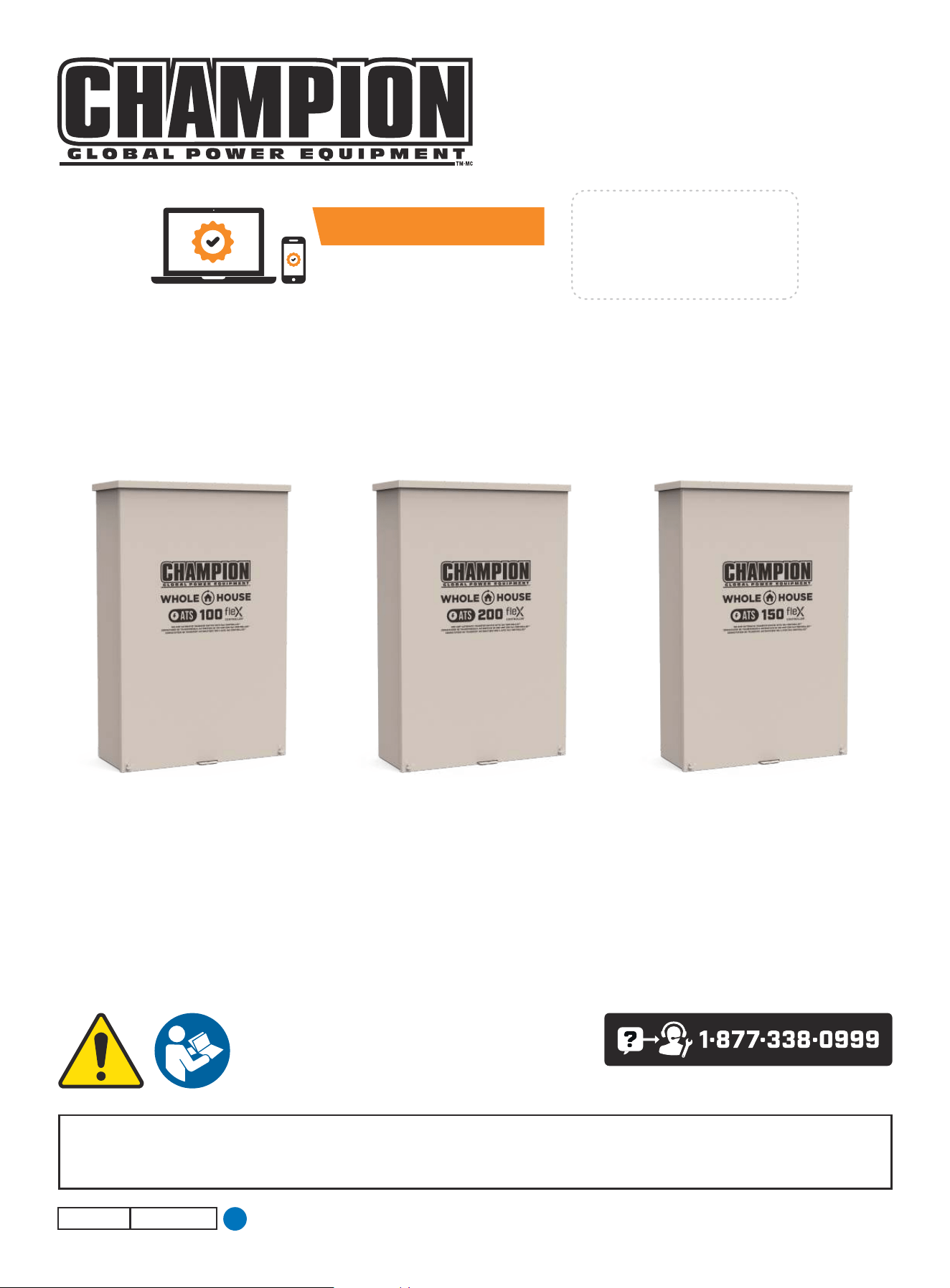
Safety Labels
These labels warn you of potential hazards that can cause serious injury. Read them carefully.
If a label comes off or becomes hard to read, contact Technical Support Team for possible replacement.
HANGTAG/LABEL DESCRIPTION PART NUMBER
1
1681-T-SF-B
ATTENTION
ALTERNATE POWER SOURCE AVAILABLE -
STANDBY GENERATOR ON PREMISES.
ATTENTION
AUTRE SOURCE DE COURANT DISPONIBLE -
GENERATEUR SUR SITE.
ATENCIÓN
FUENTE DE CORRIENTE ALTERNA DISPONIBLE -
GENERADOR DE RESERVA EN EL SITIO.
GENERATOR LOCATION:
UBICACIÓN DEL GENERADOR:
EMPLACEMENT DU GENERATEUR:
DO NOT REMOVE \ NO REMUEVA \ NE PAS ENLE VER
NW
W E
N NE
SW S SE
Alternate Power Source
1681-T-SF
(1 per unit)
Loose in IM bag.
2
5398 -T-SF -A
CAUTION
MULTIPLE SOURCES OF POWER -
STANDBY GENERATOR ON PREMISES.
ATTENTION
SOURCES D'ÉNERGIE MULTIPLES -
GENERATEUR SUR SITE.
PRECAUCIÓN
MÚLTIPLES FUENTES DE ENERGÍA -
GENERADOR DE RESERVA EN EL SITIO.
GENERATOR LOCATION:
UBICACIÓN DEL GENERADOR:
EMPLACEMENT DU GENERATEUR:
DO NOT REMOVE \ NO REMUEVA \ NE PAS ENLE VER
NW
W E
N NE
SW S SE
Multiple Sources of Power
5398-T-SF
(1 per unit)
Loose in IM bag.
3
This switch will not transfer if overcurrent device
opens due to fault.
CAUTION
Cet interrupteur ne sera pas transfere si le
dispositif a maximum de courant
s’ouvre par errur.
MISE EN GARDE
Este interruptor no se transferira si el dispositivo
de sobrecorriente se abre debido a una falla.
PRECAUCIÓN
1943-L-PR-A
Caution. Overcurrent device. 1943-L-PR
4
DANGER PELIGRO DANGER
4640-L-SF-A
Electrical shock hazard. High voltage inside. May cause injur y or death. A lways
disconnect all sources of supply before service or manual operation. Replace
protective cover after service or installation.
Peligro de descarga
eléctrica. Alta tensión en
el interior. Puede causar
lesiones o la muerte.
Desconecte siempre todas
las fuentes de aliment ación
antes de realizar cualquier
operación de
mantenimiento o manual.
Vuelva a colocar la cubier ta
protectora después del
servicio o la instalación.
Risque de choc électrique. Haute tension à l'intérieur. Peut provoquer des
blessures ou la mort. Débranchez toujours toutes les sources d’alimentation
avant l’entretien ou l’opération manuelle. Remplacez le couvercle de
protection après l'entretien ou l'installation.
Danger. Electrocution shock hazard. 4640-L-SF
5
4636-L-OP-A
DANGER
Electrical shock hazard. This panel should only be removed by an
authorized Service Dealer or a qualified electrician; high voltage inside.
May cause injury or death. Always disconnect all sources of supply before
service or manual operation.
PELIGRO
Peligro de descarga eléctrica. Este panel sólo debe ser desmontado por un
Servicio Técnico autorizado o un electricista calificado; alta tensión en el
interior. Puede causar lesiones o la muerte. Desconecte siempre todas las
fuentes de alimentación antes de realizar cualquier
operación de mantenimiento o manual.
DANGER
Risque de choc électrique. Ce panneau ne doit être retiré que par un
revendeur de service agréé ou un électricien qualifié; haute tension à
l'intérieur. Peut provoquer des blessures ou la mort. Débranchez toujours
toutes les sources d’alimentation avant l’entretien ou l’opération manuelle.
Danger. Electrocution shock hazard. 4 6 36-L- OP
6
DANGER PELIGRO DANGER
Electrical shock hazard. High voltage inside. May cause injury or death. Always
disconnect all sources of supply before service or manual operation. Replace
protective cover after service or installation.
Peligro de descarga eléctrica. Alta ten sión en el interior. Puede caus ar lesiones o la
muerte. Desconecte siempre todas las fuentes de aliment ación an tes de rea lizar
cualquier operación de mantenimiento o manual. Vuelva a colocar la cubierta
protectora después del servicio o la instalación.
Risque de choc électrique. Haute tension à l'intérieur.
Peut provoquer des blessures ou
la mort. Débranchez toujours
toutes les sources
d’aliment ation avant l’entretien
ou l’opération manuelle.
Remplacez le couvercle de
protec tion après l'entr etien ou
l'installation.
4656-L-SF-A
Danger. Electrocution shock hazard. 4656-L-SF
7
More than one live circuit - disconnect all sou rces of supply before servicing.
Más de un circuito en vivo - desconecte toda s las fuentes de suministro antes de dar servicio.
Plusieurs circuits sous tension - d ébranchez toutes les sources d’alimentation avant de procéder à l’entredien.
DANGER PELIGRO DANGER
Electrical shock hazard. This panel should only be removed by an authorized S ervice Dealer or a
qualified electrician; high voltage insi de. May cause injury or death. Always disconnect all sources
of supply before service or manual operation.
Peligro de descarga eléct rica. Este panel sólo debe ser desmontado por un Serv icio Técnico
autorizado o un electricist a calificado; alta tensión en el interior. Puede causar lesiones o la
muerte. Desconecte siempre t odas las fuentes de alimentación antes de realizar cualquier
operación de mantenimiento o manual.
Risque de choc électrique. Ce panneau ne doit être retiré que par u n revendeur de service agréé
ou un électricien qualifié ; haute tensio n à l'intérieur. Peut provoquer des blessures ou la mo rt.
Débranchez toujours toutes les s ources d’alimentation avant l’entretien ou l’opération manuelle.
WARNING ADVERTENCIA AVERTISSEMENT
4635-L-SF-A
Manual
Operation
Switch
Interruptor de
operación manual
Interrupteur de
fonctionnement
manuel
UTILITY
UTILIDAD
UTILITÉ
GENERATOR
GENERADOR
GÉNÉRATRICE
OFF
APAGA DO
ARRÊT
Danger. Electrocution shock hazard. 4635-L-SF
WHOLE HOUSE AUTOMATIC TRANSFER SWITCH - ALL fleX CONTROLLER™
MODELS
IMPORTANT SAFETY INSTRUCTIONS
6
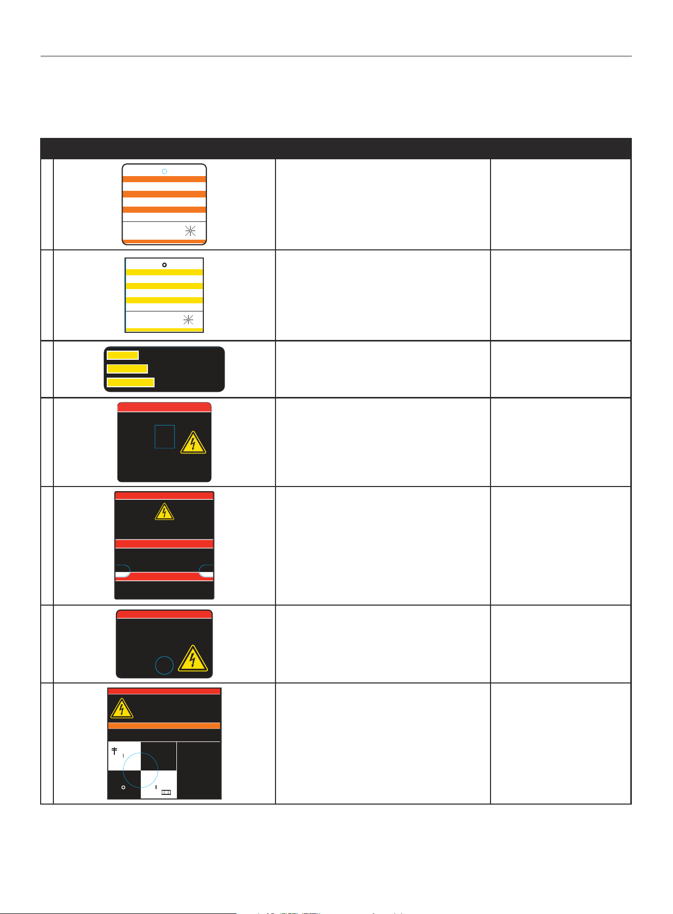
HANGTAG/LABEL DESCRIPTION PART NUMBER
8
3454-L-SF-B
Shock hazard exists if grounding electrode conductor or bonding jumper
connection in this equipment is removed while alternate source(s) is
energized.
Existe peligro de choque si se elimina el conductor del electrodo de conexión
a tierra o la conexión del puente de unión en este equipo mientras se
energizan las fuentes alternativas.
Il existe un risque d'électrocution si le conducteur de l'électrode de
mise à la terre ou la connexion du cavalier de liaison de cet équipement
est retiré alors que la ou les autres sources sont sous tension.
WARNING ADVERTENCIA AVERTISSEMENT
ATS Ground Hazard
3454-L-SF
(1 per unit)
Loose in IM bag.
9
5397-L-SF-A
MULTIPLE SOURCES OF POWER -
STANDBY GENERATOR ON PREMISES.
SOURCES D'ÉNERGIE MULTIPLES -
GENERATEUR SUR SITE.
MÚLTIPLES FUENTES DE ENERGÍA -
GENERADOR DE RESERVA EN EL SITIO.
GENERATOR LOCATION:
UBICACIÓN DEL GENERADOR:
EMPLACEMENT DU GENERATEUR:
NW
W E
N NE
SW S SE
CAUTION
PRECAUCIÓN
MISE EN GARDE
DO NOT REMOVE \ NO REMUEVA \ NE PAS ENLEVER
Multiple Sources of Power
5 39 7- L-S F
(2 per unit)
Loose in IM bag.
10
4642-L-SF-B
ALTERNATE POWER SOURCE AVAILABLE -
STANDBY GENERATOR ON PREMISES.
AUTRE SOURCE DE COURANT DISPONIBLE -
GENERATEUR SUR SITE.
FUENTE DE CORRIENTE ALTERNA DISPONIBLE -
GENERADOR DE RESERVA EN EL SITIO.
GENERATOR LOCATION:
UBICACIÓN DEL GENERADOR:
EMPLACEMENT DU GENERATEUR:
NW
W E
N NE
SW S SE
ATTENTION
ATENCIÓN
ATTENTION
DO NOT REMOVE \ NO REMUEVA \ NE PAS ENLEVER
Alternate Power Source
4 64 2-L-S F
(2 per unit)
Loose in IM bag.
WHOLE HOUSE AUTOMATIC TRANSFER SWITCH - ALL fleX CONTROLLER™
MODELS
IMPORTANT SAFETY INSTRUCTIONS
7
Safety Symbols
Some of the following symbols may be used on this product. Please study them and learn their meaning. Proper interpretation of these
symbols will allow you to more safely operate the product.
SYMBOL MEANING
Read Installation Manual. To reduce the risk of injury, user must read and understand installation
manual before using this product.
Ground. Consult with local electrician to determine grounding requirements before operation.
Electric Shock. Improper connections can create an electrocution hazard.
WHOLE HOUSE AUTOMATIC TRANSFER SWITCH - ALL fleX CONTROLLER™
MODELS
CONTROLS AND FEATURES
8
CONTROLS AND FEATURES
Read this installation manual before installing your transfer switch. Familiarize yourself with the location and function of the controls and
features. Save this manual for future reference.
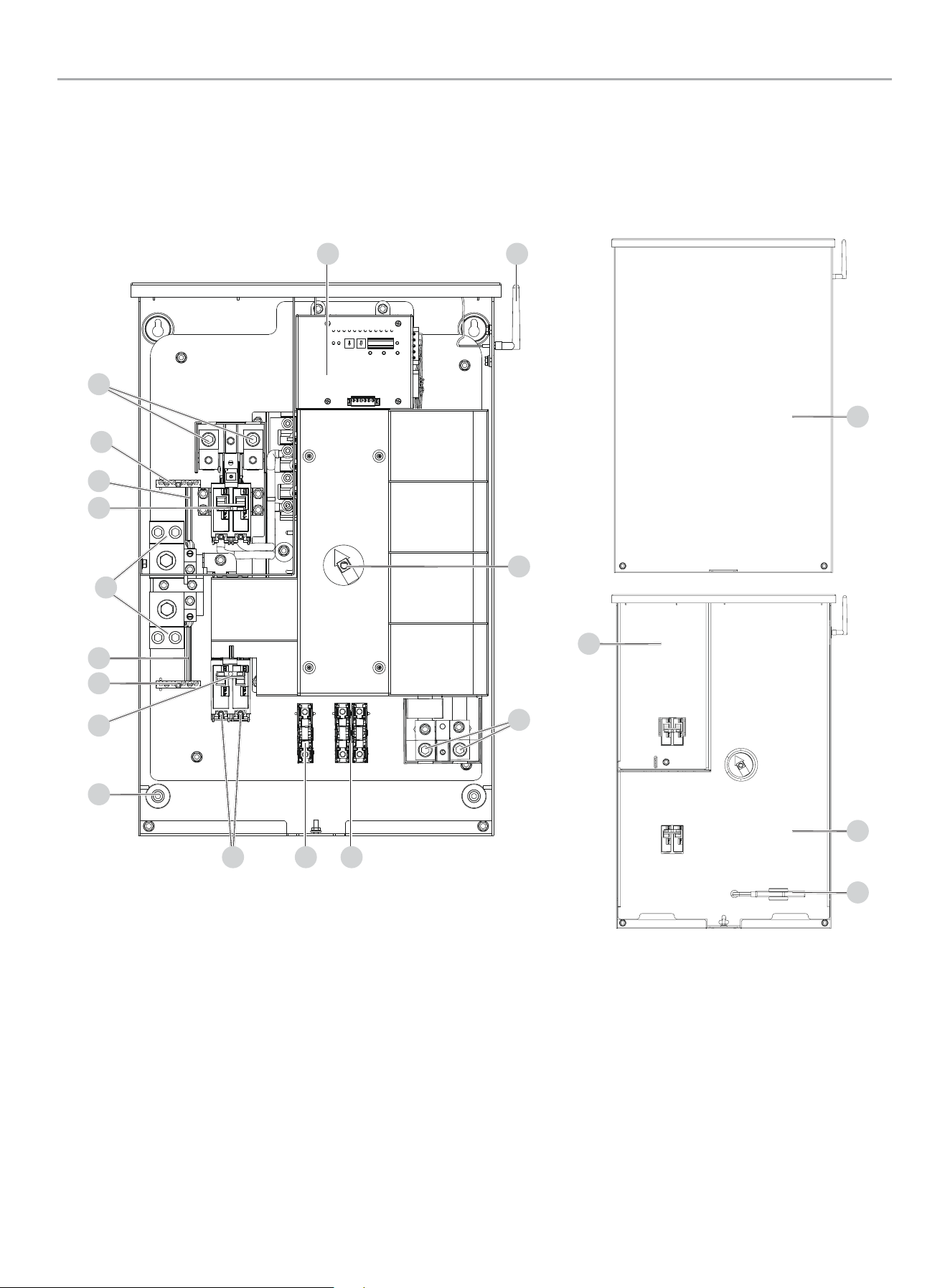
Champion Automatic Transfer Switch with fleX Controller
™
Module - Model 201020 (100A)
1. fleX Controller
™
2. Antenna
3. Manual Operation Switch
4. Load L1 and L2 Terminals (L1/L2) - under plastic cover
5. Two Wire Sensing Fuse Block
6. Battery Charger Fuse Block
7. Generator Supply L1 and L2 Terminals (G-L1/G-L2)
8. Mounting Holes - 1 in each corner (4 Total)
9. Generator Circuit Breaker- 100A
10. Ground Bar
11. Ground Bond Wire
12. Neutral Bar
13. Utility Circuit Breaker/ Utility Service Disconnect
14. Utility Supply L1 and L2 Terminals (U-L1/U-L2) - under plastic
cover
15. Dead Front – Utility Lockout
16. Manual Operation Switch Handle
17. Dead Front
18. Front Cover
1 2
567
3
4
15
16
17
18
8
9
10
10
11
11
13
14
12
WHOLE HOUSE AUTOMATIC TRANSFER SWITCH - ALL fleX CONTROLLER™
MODELS
CONTROLS AND FEATURES
9
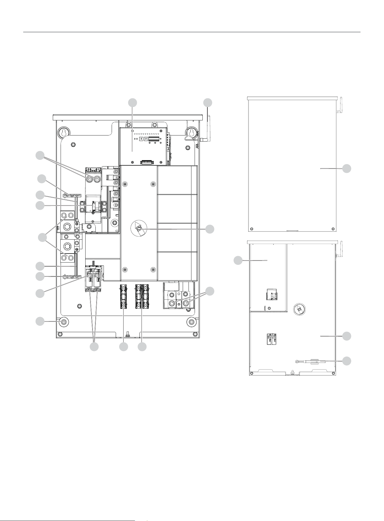
1. fleX Controller™
2. Antenna
3. Manual Operation Switch
4. Load L1 and L2 Terminals (L1/L2) - under plastic cover
5. Two Wire Sensing Fuse Block
6. Battery Charger Fuse Block
7. Generator Supply L1 and L2 Terminals (G-L1/G-L2)
8. Mounting Holes - 1 in each corner (4 Total)
9. Generator Circuit Breaker- 201039 (200A) / 201355 (150A)
10. Ground Bar
11. Ground Bond Wire
12. Neutral Bar
13. Utility Circuit Breaker/ Utility Service Disconnect
14. Utility Supply L1 and L2 Terminals (U-L1/U-L2)
15. Dead Front – Utility Lockout
16. Manual Operation Switch Handle and Storage
17. Dead Front
18. Front Cover
15
16
17
18
Champion Automatic Transfer Switch with fleX Controller
™
Module -
Models 201039 (200A) / 201355 (150A)
1 2
567
3
4
8
9
10
11
13
14
10
11
12

WHOLE HOUSE AUTOMATIC TRANSFER SWITCH - ALL fleX CONTROLLER™
MODELS
CONTROLS AND FEATURES
10
Safety and Dataplate Labels
These labels warn you of potential hazards that can cause serious injury. Read them carefully.
If a label comes off or becomes hard to read, contact Technical Support Team for possible replacement.
LABEL DESCRIPTION
A
4639-L-PR-A
Contains FCC ID: YA3-CPEWIFI0 2
This device c omplies with Part 15 of the FCC Rules. Operation is subject to the
following two conditions: (1) This device may not cause harmful interference, and (2)
This device must accept a ny interference received, inclu ding inter ference that may
cause undesired operation.
Contiene F CC ID: YA3- CPEW IFI02
Este dispositivo cump le con la par te 15 de las norma s FCC. La operación está sujeta a
las siguientes dos condiciones: (1) Est e disposit ivo no puede causar interferencia dañina,
y (2) Este dispositivo debe aceptar cualquier interferencia recibida, incluidas las
interferencias que puedan provocar un funcionamiento no deseado.
Contient
FCC ID: YA3-CPEWIFI02
Ces dispositifs se conforment à la section 15 du règlement de la FC C. Le fonc tionnement
est assuje tti aux c onditions suivantes : (1) Ce dispositif ne doit pas g énérer
d’interférences nuisibles, et (2) ce dispositif doit accepter toute interférence qui peut
causer un fonctionnement non désiré.
Contains IC: 10186A-CPEWIFI02
This device c omplies with Industr y Canada license-exempt RSS standard(s). Operation
is subject to t he following t wo conditions: (1) this device may not cause in terfer ence,
and (2) this dev ice must accept any interference, including in terfer ence that may c ause
undesired operation of the device.
CAN ICES-3 (B)/NMB-3 (B)
Contiene I C: 10186A-C PEWI FI02
Este dispositivo cump le las norma s RSS exent as de licencia de Indust ry Canada. Su
funcionamiento está sujeto a las dos condicio nes siguientes: (1) este disp ositivo no
puede causar interferencias, y (2) este dispositivo debe aceptar cualquier interferencia,
incluidas las interferencias que puedan causar un funcionamiento no deseado del
dispositivo.
CAN ICES-3 (B)/NMB-3 (B)
Contient IC: 10186A-CPEWIFI02
Cet appareil est conforme aux nor mes RSS exemptes de licence d'Industrie Canada . Son
fonctionnement est soumis aux deu x conditio ns suivantes: (1) cet appareil ne doit pas
provoquer d'interférences, et (2) cet appareil doit accepter toute interférence, y compris
les interférences susceptibles d'entraîner un fonctionnement indésirable de l'appareil.
CAN ICES-3 (B)/NMB-3 (B)
FCC
B
1941-L-OP-A
PASSWORD
CONTRASEÑA
MOT DE PASSE
12345678
WiFi SSID and
password
C
4629 -L-PR-A
MODEL
MODÈLE
AC VOLTS
VOLTS C.A.
201039
120/240
UTILITY
UTILITÉ
GENERATOR
GÉNÉRATRICE
200A
200A
Conforms to CSA
Std. C22.2
NO. 178.1 and UL
Std. NO. 1008
Conforme à CSA
Std. C22.2
N° 178.1 et UL
Std. N° 1008
#######
ACTIVATE YOUR
WARRANTY
ACTIVEZ VOTRE
GARANTIE
CHAMPION POWER EQUIPMENT, INC.
6370 S PIONEER WAY, UNIT 101
LAS VEGAS, NV 89113
USA / É.-U.
1-877-338-0999
WWW.CHAMPIONPOWEREQUIPMENT.COM
MADE IN CHINA / FABRIQUÉ EN CHINE
SERIAL NO.
N° DE SÉRIE
XXXXXXXXXXXX
201039 Dataplate
4627-L-PR-A
MODEL
MODÈLE
AC VOLTS
VOLTS C.A.
201355
120/240
UTILITY
UTILITÉ
GENERATOR
GÉNÉRATRICE
150A
150A
Conforms to CSA
Std. C22.2
NO. 178.1 and UL
Std. NO. 1008
Conforme à CSA
Std. C22.2
N° 178.1 et UL
Std. N° 1008
#######
ACTIVATE YOUR
WARRANTY
ACTIVEZ VOTRE
GARANTIE
CHAMPION POWER EQUIPMENT, INC.
6370 S PIONEER WAY, UNIT 101
LAS VEGAS, NV 89113
USA / É.-U.
1-877-338-0999
WWW.CHAMPIONPOWEREQUIPMENT.COM
MADE IN CHINA / FABRIQUÉ EN CHINE
SERIAL NO.
N° DE SÉRIE
XXXXXXXXXXXX
201355 Dataplate
4625- L-PR-A
MODEL
MODÈLE
AC VOLTS
VOLTS C.A.
201020
120/240
UTILITY
UTILITÉ
GENERATOR
GÉNÉRATRICE
100A
100A
Conforms to CSA
Std. C22.2
NO. 178.1 and UL
Std. NO. 1008
Conforme à CSA
Std. C22.2
N° 178.1 et UL
Std. N° 1008
#######
ACTIVATE YOUR
WARRANTY
ACTIVEZ VOTRE
GARANTIE
CHAMPION POWER EQUIPMENT, INC.
6370 S PIONEER WAY, UNIT 101
LAS VEGAS, NV 89113
USA / É.-U.
1-877-338-0999
WWW.CHAMPIONPOWEREQUIPMENT.COM
MADE IN CHINA / FABRIQUÉ EN CHINE
SERIAL NO.
N° DE SÉRIE
XXXXXXXXXXXX
201020 Dataplate
A
B
Back Inside
C
WHOLE HOUSE AUTOMATIC TRANSFER SWITCH - ALL fleX CONTROLLER™
MODELS
MANUAL SWITCH OPERATION
11
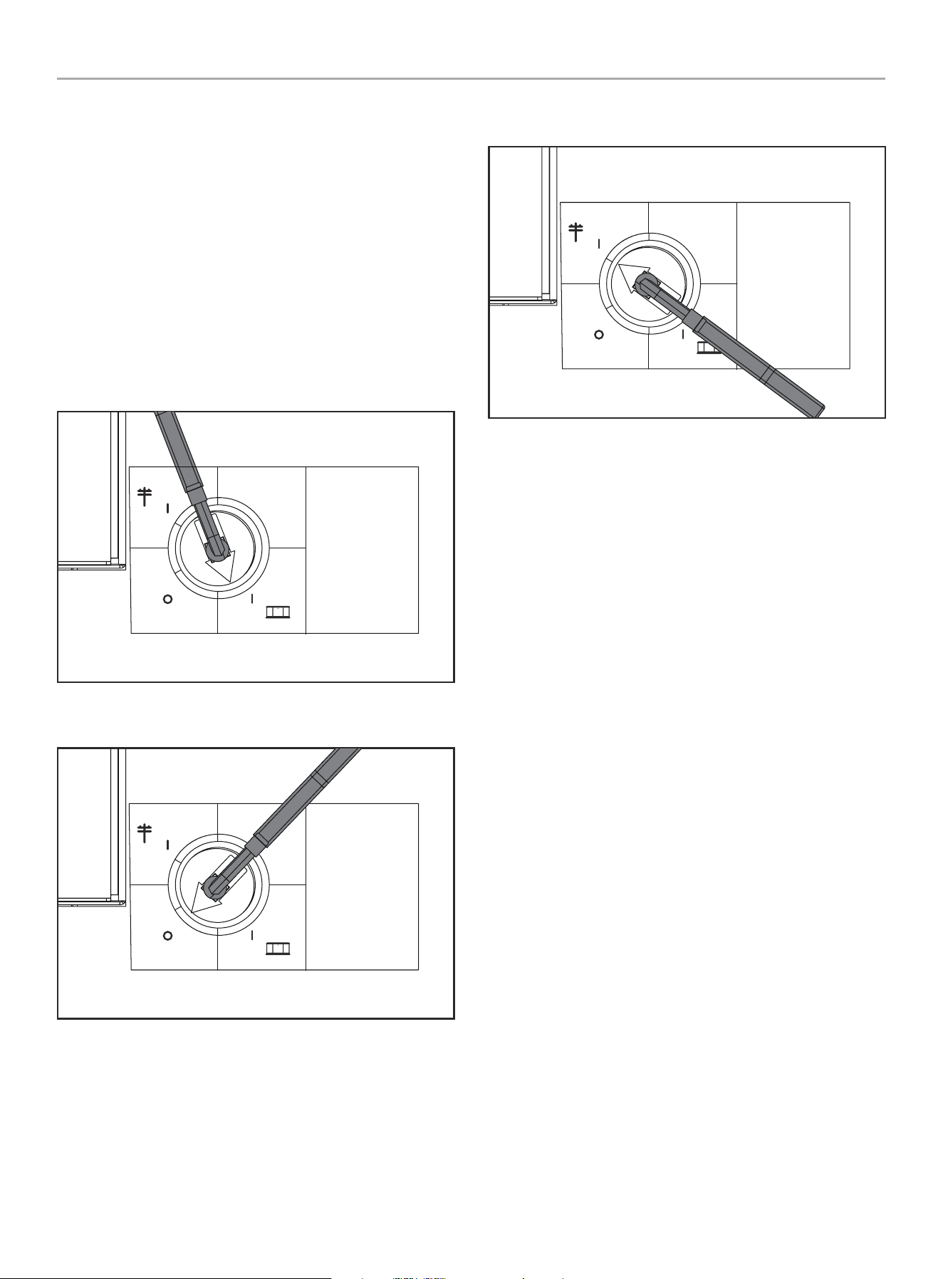
MANUAL SWITCH OPERATION
fleX Automatic Transfer Switch (ATS) has the ability to switch
manually between generator or utility as required. The ATS has
a storage position (16) for a manual operation switch handle that
allows the transfer between generator, OFF, and utility. In the
event of manual transfer need, adjust the transfer switch manually
by removing the manual operation switch handle (16) and inserting
into the keyed center of the switch to rotate.
1. Remove Manual Operation Switch Handle, and insert the
handle into the center switch key way.
2. Move to either Generator, Off, or Utility.
Generator - move the switch down, once an audible click is heard,
move fully so the red arrow points fully in the generator zone.
Manual
Operation
Switch
Interruptor de
operación manual
Interrupteur de
fonctionnement
manuel
UTILITY
UTILIDAD
UTILITÉ
GENERATOR
GENERADOR
GÉNÉRATRICE
OFF
APAGADO
ARRÊT
Off - move through the switch position into Off, until an audible
click is heard, move so the red arrow points fully in the OFF zone.
Manual
Operation
Switch
Interruptor de
operación manual
Interrupteur de
fonctionnement
manuel
UTILITY
UTILIDAD
UTILITÉ
GENERATOR
GENERADOR
GÉNÉRATRICE
OFF
APAGADO
ARRÊT
Utility - move the switch up, once the audible click is heard, move
fully so the arrow points fully in the utility zone.
Manual
Operation
Switch
Interruptor de
operación manual
Interrupteur de
fonctionnement
manuel
UTILITY
UTILIDAD
UTILITÉ
GENERATOR
GENERADOR
GÉNÉRATRICE
OFF
APAGADO
ARRÊT
WHOLE HOUSE AUTOMATIC TRANSFER SWITCH - ALL fleX CONTROLLER™
MODELS
UNPACKING
12
UNPACKING
1. Use care when unpacking to avoid damaging transfer switch
components.
2. Allow the ATS to acclimate to room temperature for
a minimum of 24 hours before unpacking to prevent
condensation on the electrical apparatus.
3. Use a wet/dry vacuum cleaner or a dry cloth to remove dirt
and packing material that may have accumulated in the
transfer switch or any of its components during storage.
4. Do not use compressed air to clean the switch, cleaning with
compressed air can cause debris to lodge in the components
and damage the switch per the ATS manufacturers
specifications.
5. Retain the ATS manual with or near the ATS for future
reference.
TOOLS REQUIRED NOT INCLUDED
5/16 in. Hex Wrench
Mounting Hardware
Line Voltage Wire
1/4 in. Flat Screwdriver
Conduit
Fittings
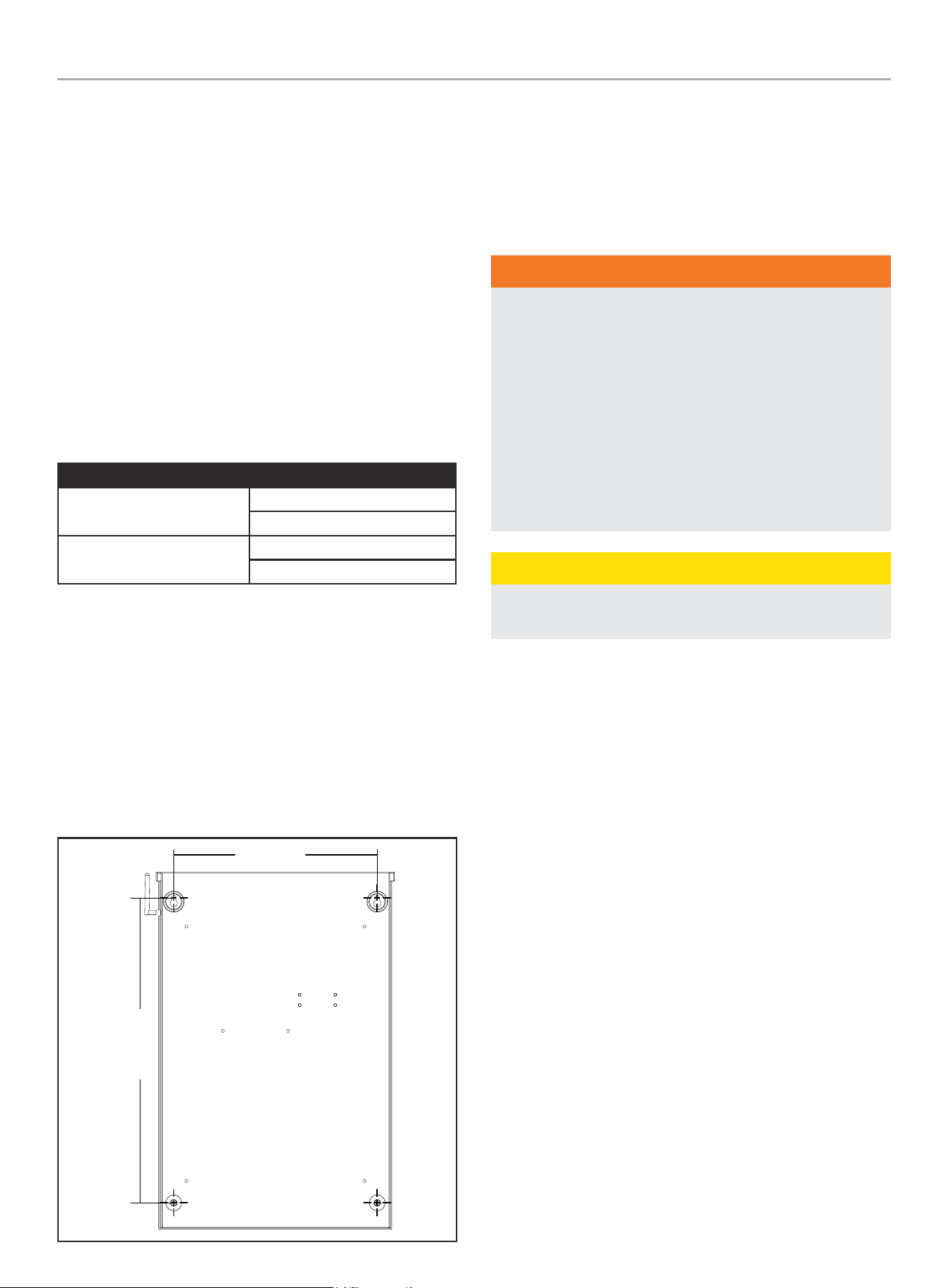
Location and Mounting
Install the ATS as close as possible to utility meter socket. Wires
will run between the ATS and main distribution panel, proper
installation and conduit are required by code. Mount the ATS
vertically to a rigid supporting structure. To prevent the ATS or
enclosure box from distortion, level all mounting points; use
washers behind the mounting holes (outside the enclosure,
between enclosure and supporting structure), see following image.
The recommended fasteners are 1/4” lag screws. Always follow
local code.
24 in.
(610 mm)
16.1 in.
(410 mm)
Electrical Grommet(s)
Grommets can be used in any enclosure knockout for NEMA 1
installations. Grommets can only be used in the bottom enclosure
knockouts for NEMA 3R installations, when installed outside.
Installation Wiring for ATS Utility Socket
WARNING
The manufacturer recommends that a licensed electrician or
an individual with complete knowledge of electricity perform
these procedures.
Always be certain that the power from the main panel is
turned “OFF” and all backup sources are locked out prior to
removal of the cover or removal of any wiring of the utility
main electrical distribution panel.
Be aware, automatic start generators will start upon loss of
utility main power unless locked in the “OFF” position.
Failure to do so could result in serious injury or death.
CAUTION
Consult with your Local municipal, State and National
electrical codes for proper mandatory wiring methods.
Conductor sizes must be adequate to handle the maximum current
to which they will be subjected. The installation must comply fully
with all applicable codes, standards and regulations. Conductors
must be properly supported, of approved insulation materials,
protected by approved conduit and with the correct wire gauge
size in accordance with all applicable codes. Before connecting
wire cables to terminals, remove any surface oxides from the
cable ends with a wire brush. All power cables must enter the
enclosure through the enclosure knockouts.
1. Determine where the flexible, liquid tight conduit will pass
through the building from the inside to outside. When you
are certain that there is adequate clearance on each side of
the wall, drill a small pilot hole through the wall to mark the
location. Drill an appropriate sized hole through the sheathing
and siding.
2. In compliance with all local electrical codes, route the conduit
along ceiling/floor joists and wall studs to the location where
the conduit will pass through the wall to the exterior of the
house. Once the conduit is pulled through the wall and in
proper position to attach to the HSB generator, place silicone
caulk around the conduit on both side of the hole, inside and
outside.
3. Mount the ATS near the Utility meter socket.
WHOLE HOUSE AUTOMATIC TRANSFER SWITCH - ALL fleX CONTROLLER™
MODELS
INSTALLATION
13
INSTALLATION
Wiring the ATS
NOTICE
The fleX ATS controls the automatic startup and shutdown of
the fleX HSB using Power Line Communication (PLC). The PLC
system utilizes the L1 and L2 power wires that run between
the ATS and HSB for communication. As a result, there are no
wires that need to be run between the ATS and HSB besides
the power wires (L1, L2, N, G) and battery charger wires.
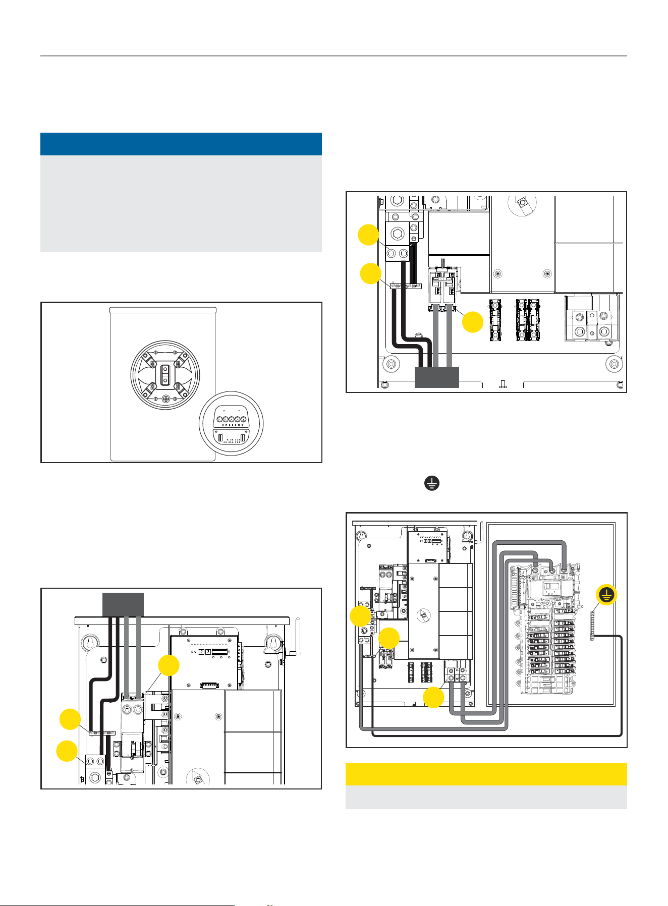
1. Have authorized utility personnel pull the utility meter from
the meter socket.
2. Remove front cover and dead front of ATS.
3. Connect Utility (U-L1 / U-L2) to ATS Utility supply terminals
(14). Torque to 275 in-lbs.
4. Connect Utility N to Neutral lug (12). Torque to 275 in-lbs.
5. Connect earth GROUND to GROUND bar (10). Torque to 35-45
in-lbs. NOTE: GROUND and NEUTRAL bonded in this panel.
14
10
12
6. Connect Generator G-L1 / G-L2 to Generator supplier
terminals (7). Torque to 45-50 in-lbs.
7. Connect Generator Neutral to neutral bar (12). Torque to
275 in-lbs.
8. Connect Generator GROUND to GROUND bar (10).
Torque to 35-45 in-lbs. NOTE: GROUND and NEUTRAL
bonded in this panel.
12
10
7
9. Connect Load bars L1 and L2 to distribution panel (4).
Torque to 275 in-lbs.
10. Pull NEUTRAL from ATS to distribution panel (12). Torque to
275 in-lbs.
11. Pull GROUND
from ATS to distribution panel (10). Torque
to 35-45 in-lbs.
4
10
12
CAUTION
Remove bond from distribution panel if installed.
WHOLE HOUSE AUTOMATIC TRANSFER SWITCH - ALL fleX CONTROLLER™
MODELS
INSTALLATION
14
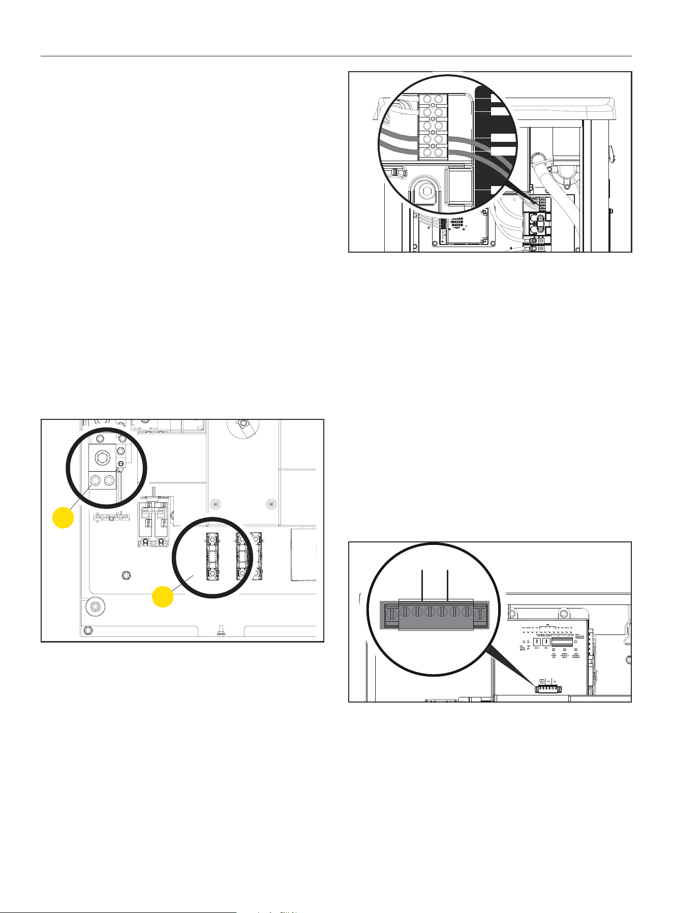
Battery Charger Wiring
The fleX Controller
™
HSB contains a 24V battery charger that is
powered by 120V AC. The battery charger receives 120V AC power
from the fleX Controller
™
ATS using the single fuse block located in
center of the ATS.
1. Run two wires from the ATS to the HSB for the battery
charger circuit.
The battery charger circuit is 120V AC, 10 amp maximum.
Wires need to be sized accordingly.
Wiring can run in the same conduit as the L1, L2, Neutral and
Ground wires from the previous section provided:
1a. Battery charger wire has an insulation rating equal to or
greater than 264VAC.
1b. Battery charger wire is suitable for outdoor installation.
1c. Allowed by local code and meets NFPA 70.
2. ATS Connections for battery charger.
2a. L1 - Bottom terminal of the fuse block in the ATS (6).
2b. Neutral - Neutral block (12).
See picture below for location of fuse block and neutral block.
12
6
3. HSB Connection for battery terminals
3a. The terminal block is prewired by the factory to the
charger L and N. A 120 VAC circuit must be installed for
battery charging from the ATS or another 120VAC circuit.
Refer to fleX controller
™
HSB installation manual for more
information.
2-Wire
COM
N
L1
L
INPUT
120V- N/L
OUTPUT-
CHARGER
Utility Sensing Fuse Block
The utility sensing fuse block is not used in a typical installation.
The fuse block is only used when connecting the Champion fleX
ATS to a non-Champion HSB that monitors utility voltage to control
automatic generator start/stop. The potential voltage between the
two fuses is 240V AC.
Do not use the utility sensing block for the battery charging circuit.
The battery charging fuse block is located next to the utility
sensing fuse block.
Low Voltage Control Relays
The fleX Controller
™
ATS has two low voltage relays that can be
used to manage the load of air conditioners or other devices that
utilize low voltage controls. The ATS’s two low voltage relays
are called AC1 and AC2 and are found on the fleX Controller
™
as
shown in the picture below.
AC1 AC2
2 WIRE
2 CABLES
2 FILS
CONNECTING TO AC1 AND AC2
For air conditioner or other low voltage controls, route your low
voltage wiring into the ATS using code appropriate conduit and
fittings. Connect the wiring to pin 1 and pin 2 of either AC1 or AC2
as shown in the previous diagram.
WHOLE HOUSE AUTOMATIC TRANSFER SWITCH - ALL fleX CONTROLLER™
MODELS
INSTALLATION
15
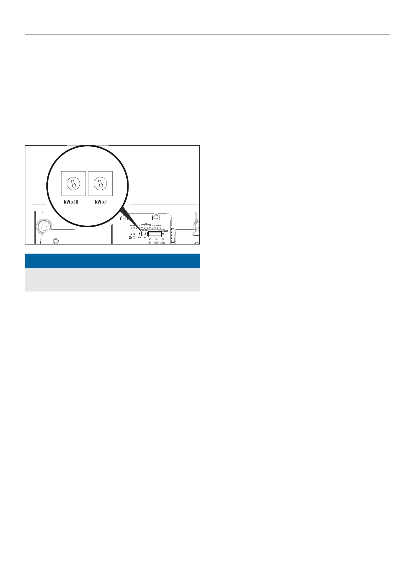
Settings on the fleX Controller
™
1. On the ATS fleX Controller
™
, set the two circular pots that
are located to the left of the DIP switches to match the rated
power output of the generator for your fuel type.
1st pot (left pot) is 10’s value, 2nd pot (right pot) is 1’s value,
do not go over generator rating. If wattage rating of generator
falls between settings choose the next lower value; e.g.
generator rating is 22,000W, set pots to 2 and 2 or if wattage
is not even 1000, set to the smaller value, e.g 12,500W, set
pots to 1 and 2..
0
1
2
3
4
5
6
7
8
9
0
1
2
3
4
5
6
7
8
9
NOTICE
All DIP switches are set to ON by default from the factory
except for switch #9 which is set to OFF.
2. Verify the DIP switches are set for your installation. Adjust as
needed.
DIP Switch Settings
Switch 1. Load Module 1 Lockout
– On= Load Module 1 is being managed. Load Module 1 is the
lowest priority of the 4 load modules. This load will be turned
off first as the ATS manages the home’s load.
– Off= Load module 1 will stay off during HSB power.
Switch 2. Load Module 2 Lockout
– On= Load Module 2 is being managed.
– Off= Load module 2 will stay off during HSB power.
Switch 3. Load Module 3 Lockout
– On= Load Module 3 is being managed.
– Off= Load module 3 will stay off during HSB power.
Switch 4. Load Module 4 Lockout
– On= Load Module 4 is being managed. Load Module 4 is the
highest priority of the 4 load modules. This load will be turned
off last as the ATS manages the homes load.
– Off= Load module 4 will stay off during HSB power.
Switch 5. Frequency Protection.
– On= All managed loads will be turned off when if the HSB
frequency drops below 58 Hz.
– Off= All managed loads will be turned off when if the HSB
frequency drops below 57 Hz.
Switch 6. Secondary ATS Bond Mode
– On= Bond mode ON
– Off= Bond mode OFF
Switch 7. Power Management
– On= ATS is managing the home’s load.
– Off= ATS has disabled power management.
Switch 8. PLC vs. Two Wire Communication
– On= ATS will control HSB startup and shutdown through PLC.
This is the preferred method of communication however it
requires the HSB to be an fleX controlled HSB.
– Off= ATS will control the start of the HSB using the 2 Wire
Relay.
Switch 9. Test HSB with Load
– On= Test occurs with load.
– Off= Test occurs without load.
Switch 10. Primary/Secondary
– On= This ATS is the primary or only ATS. <- most common.
– Off= This ATS is being controlled by a different fleX Controller
™
ATS. Used for installations that require two ATS boxes (i.e.
400A installations). When off, low voltage AC1/AC2 or LMM
connections can be made from either primary or secondary
ATS. Low voltage AC1/AC2 or LMM connections can be made
from either primary or secondary ATS. All secondary ATS AC1/
AC2 or LMM connections are controlled by the primary ATS
during generator operation. Primary ATS DIP switch 6 must be
ON.
Switch 11. Exercise Test
– On= Exercise tests will occur per the schedule that is
programmed into the fleX Controller
™
.
– Off= Exercise tests are disabled.
Switch 12. Time delay for HSB to accept load.
– On= 45 seconds.
– Off= 7 seconds.
3. Have authorized utility personnel reconnect the utility meter
to the meter socket.
4. Verify voltage at utility circuit breaker.
5. Turn on utility circuit breaker.
6. ATS fleX Controller
™
module will begin boot up process. Allow
ATS fleX Controller
™
module to fully boot up (approximately 6
minutes).
WHOLE HOUSE AUTOMATIC TRANSFER SWITCH - ALL fleX CONTROLLER™
MODELS
INSTALLATION
16
7. Home should be fully powered at this point.
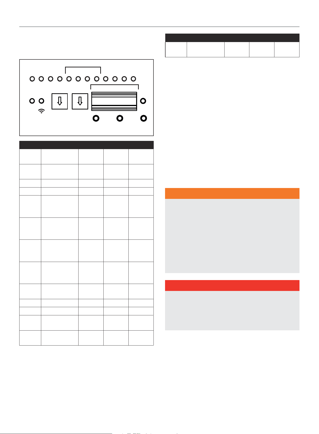
LEDs
TEST
PRUEBA
TEST
kW x10 kW x1
DEFAULT
POR DEFECTO
DÉFAUT
LEARN
APRENDER
APPRENDRE
RESET
RESTABL
RÉINITIA
PMTUTILGENAC1AC2GSTARTGSTOP
RUN
CORRER
MARCHE
WiFi
ATSPOS
1 2 3 4
LMM
ON / ENCENDIDO / MARCHE
OFF / APAGADO / ARRÊT
1 2 3 4 5 6 1211107 8 9
LED Function Off Red Green
GSTOP
Generator is
stopped
Did not
stop
Reset Off
GSTART
Generator is
running
Off Test mode Running
AC1 Air conditioner 1 Off Generator Utility
AC2 Air conditioner 2 Off Generator Utility
LMM1
Load
Management
Module 1
Off Generator Utility
LMM2
Load
Management
Module 2
Off Generator Utility
LMM3
Load
Management
Module 3
Off Generator Utility
LMM4
Load
Management
Module 4
Off Generator Utility
GEN
Generator
condition
Off Fault Normal
UTIL Utility Off Fault Normal
ATSPOS ATS position Off Generator Utility
PMT
Power
management
Off Generator Utility
RUN
flex Controller is
powered
Off Fault Normal
LED Function Off Red Green
Wi-Fi
Wireless
Connectivity
Off
Not
connected
Connected
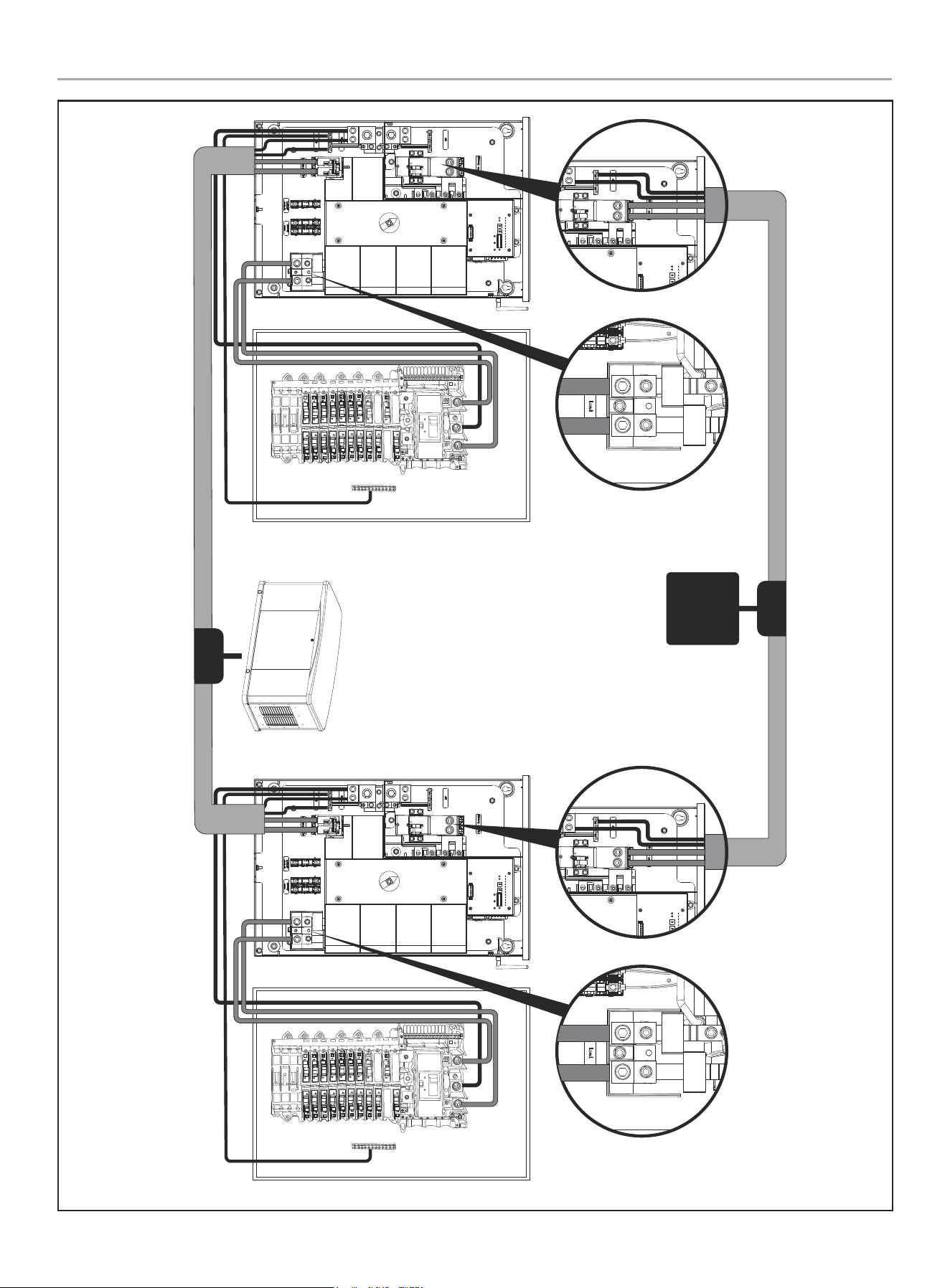
400A Installation
The following instructions are for installing two (2) 200A ATSs,
allowing 400A service.
Primary ATS installed and connected to primary distribution
panel as shown in the Installation Manual for the fleX Controller
™
Automatic Transfer Switch (ATS), in “Wiring the ATS.”
Secondary ATS installed and connected to secondary distribution
panel as shown below.
Models affected
– 201202
– 201039
HSB output (L1, L2, N, G) must be brought to a junction box
(customer supplied) and split to supply both primary ATS and
secondary ATS.
WARNING
Have only qualified personnel who are familiar with applicable
codes, standards and regulations install and service the
generator. ALWAYS comply with local, state, province, or
territory and national electrical and building codes when
installing the generator. NEVER alter the recommended
installation in a way that would render the unit noncompliant
with these codes. ALWAYS comply with regulations that
Occupational Safety and Health Administration (OSHA) has
established. ENSURE the generator is installed following the
manufacturer’s instructions.
DANGER
Gaseous fuels such as NG and LPG are highly explosive.
Even the slightest spark can ignite such fuels and cause an
explosion, which could cause burns, fire or explosion resulting
in serious injury, property damage or even death. NO leakage
is permitted.

WHOLE HOUSE AUTOMATIC TRANSFER SWITCH - ALL fleX CONTROLLER™
MODELS
INSTALLATION
17
WARNING
ALWAYS prevent the generator from starting while the covers
are open. The generator may crank and start at any time
without notice. Follow these steps in order:
1. Pull fuse from fleX Controller
™
panel and secure with tape
to the panel.
2. Disconnect the NEGATIVE, NEG or (-) battery cable first,
and then remove the POSITIVE, POS or (+) battery cable.
To return the generator to service, follow these steps in order:
1. Connect the POSITIVE, POS or (+) battery cable first, and
then connect the NEGATIVE, NEG or (-) battery cable.
2. Remove taped fuse from the panel and reinstall into the
fleX Controller
™
WHOLE HOUSE AUTOMATIC TRANSFER SWITCH - ALL fleX CONTROLLER™
MODELS
INSTALLATION
18
UTIL
UTIL
Primary ATS Primary 200A
Distribution Panel
400A Topology 2x 200A ATS
200A
Secondary ATS Secondary 200A
Distribution Panel
200A
400A
Utility
Junction
Box
Junction
Box
WHOLE HOUSE AUTOMATIC TRANSFER SWITCH - ALL fleX CONTROLLER™
MODELS
INSTALLATION
19
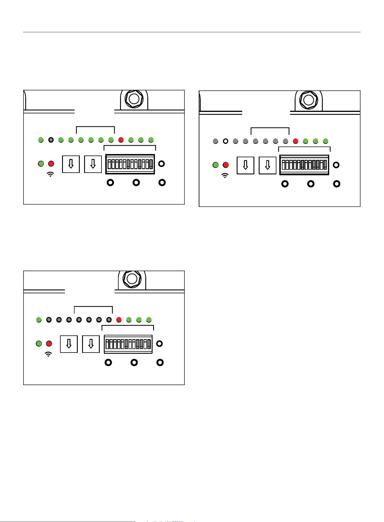
Primary ATS LEDs
1 - 5, 7, 8, 10 & 11 DIP switches are in “ON” position.
6, 9 and 12 DIP switches are in the “OFF” position.
The LEDs will illuminate after utility power is supplied.
TEST
PRUEBA
TEST
kW x10 kW x1
DEFAULT
POR DEFECTO
DÉFAUT
LEARN
APRENDER
APPRENDRE
RESET
RESTABLECER
RÉINITIALISER
PMTUTILGENAC1AC2GSTARTGSTOP
RUN
CORRER
MARCHE
WiFi
ATSPOS
1 2 3 4
LMM
ON / ENCENDIDO / MARCHE
OFF / APAGADO / ARRÊT
1 2 3 4 5 6 1211107 8 9
Primary
Primarios
Primaires
ON
1 2 3 4 5 6 7 8 9 10 11 12
Secondary ATS LEDs
1 -5, 7, 8 & 11 DIP switches are in “ON” position.
6, 9, 10 and 12 DIP switches are in the “OFF” position.
The LEDs will illuminate after utility power is supplied.
TEST
PRUEBA
TEST
kW x10 kW x1
DEFAULT
POR DEFECTO
DÉFAUT
LEARN
APRENDER
APPRENDRE
RESET
RESTABLECER
RÉINITIALISER
PMTUTILGENAC1AC2GSTARTGSTOP
RUN
CORRER
MARCHE
WiFi
ATSPOS
1 2 3 4
LMM
ON / ENCENDIDO / MARCHE
OFF / APAGADO / ARRÊT
1 2 3 4 5 6 1211107 8 9
Secondary
Secundarios
Secondaires
ON
1 2 3 4 5 6 7 8 9 10 11 12
The LEDs shown pertain only to fleX Controller
™
Load
Management Modules (LMM).
Both LMM 1 through 4 (LMM1-4), GSTOP/ GSTART, and AC1/AC2
are not illuminated. This is normal and will occur when DIP switch
10 is in the OFF (Secondary ATS) position.
ON
1 2 3 4 5 6 7 8 9 10 11 12
TEST
PRUEBA
TEST
kW x10 kW x1
DEFAULT
POR DEFECTO
DÉFAUT
LEARN
APRENDER
APPRENDRE
RESET
RESTABLECER
RÉINITIALISER
PMTUTILGENAC1AC2GSTARTGSTOP
RUN
CORRER
MARCHE
WiFi
ATSPOS
1 2 3 4
LMM
ON / ENCENDIDO / MARCHE
OFF / APAGADO / ARRÊT
1 2 3 4 5 6 1211107 8 9
Secondary
Secundarios
Secondaires
For support, see Settings on the fleX Controller
™
section.
LMM modules can be attached to either primary or secondary
distribution panel circuits but will be controlled only by primary
ATS. LMM priority is determined by primary ATS and loads will be
controlled as required per the settings input to primary ATS.
Primary ATS kW setting must match HSB rating. Primary ATS will
communicate with secondary ATS to determine total load usage
and determine need to activate LMM modules (if applicable).
When performing LEARN function for loads on LMMs; both
primary and secondary ATS need to be active, but only the primary
ATS is required to LEARN.
HSB is fully controlled by primary ATS. Starting and stopping along
with exercise requirement commands are sent by primary ATS.
Wi-Fi connection should be made at install time to both primary
and secondary ATS units to set day, date, time variables.
Secondary ATS does not need exercise day, date, time set
although it will not affect any operation if set.
HSB battery charge connection (120VAC) can come from either
primary or secondary ATS or primary or secondary distribution
panel. The connection should be fused with no greater than 15A
regardless of source.
Low voltage AC1/AC2 or LMM connections can be made from
either primary or secondary ATS. All secondary ATS AC1/AC2
or LMM connections are controlled by the primary ATS during
generator operation.
WHOLE HOUSE AUTOMATIC TRANSFER SWITCH - ALL fleX CONTROLLER™
MODELS
INSTALLATION
20
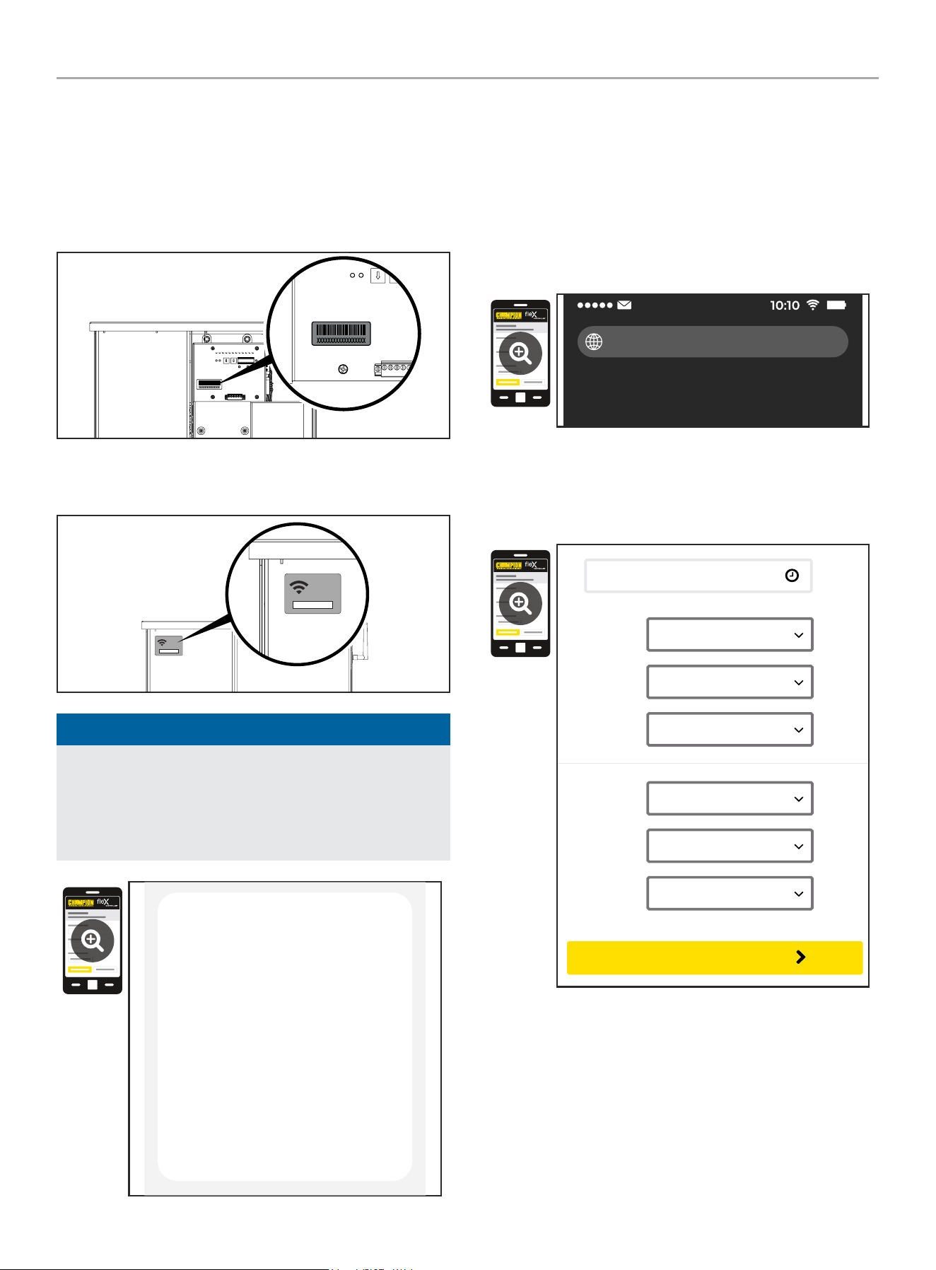
Wi-Fi Setup Method
1. Use a Wi-Fi enabled device (laptop, smart phone, tablet, etc.)
in near proximity to the ATS.
2. Search and connect to network name (SSID) “Champion
####” where #### will match the last four digits of the serial
number that is printed on the control board.
2a. The password for the network is located on a label on the
dead front of the ATS.
PASSWORD
CONTRASEÑA
MOT DE PASSE
12345678
PASSWORD
CONTRASEÑA
MOT DE PASSE
12345678
NOTICE
During the setup your device will disconnect from the internet.
The Champion Wi-Fi is a direct connection between your
device (laptop, smart phone, tablet, etc.) and the ATS, and it
does not connect to the internet. Some Android devices may
show the following screen – Choose “Connect only this time.”
Internet may not be available.
If you want to connect this network without
internet access, you can connect only this
time or you can set your phone to always
connect to it even if internet isn’t available.
You can change this in Settings >
Connections > Wi-fi > ADVANCED >
Switch to mobile data > Network
exceptions
Connect only this time
Allow switch
Stay connected
3. After connecting Wi-Fi, open your device’s web browser. In
the browser address change the address to 192.168.0.90 and
begin search. This will direct your browser to the Champion
fleX Controller
™
Home Standby Generator Settings page
located on the ATS. If your device’s web browser does not
load the Champion fleX Controller
™
Home Standby Generator
Settings Page but rather stays connected to the internet, turn
off mobile data on the device (if applicable) and make sure
the device is not connected to any other networks.
192.168.0.90
4. On the Champion fleX Controller
™
Home Standby Generator
Settings Page, set the date and time. Use either the dropdown
boxes or the “USE THIS DEVICE DATE & TIME” button to set
the time and date.
USE DEVICE DATE & TIME
Date:
Choose Month...
Choose Date...
Choose Year...
Time:
Choose Hour...
Choose Minute...
Choose AM/PM...
CONFIRM DATE & TIME
WHOLE HOUSE AUTOMATIC TRANSFER SWITCH - ALL fleX CONTROLLER™
MODELS
INSTALLATION
21
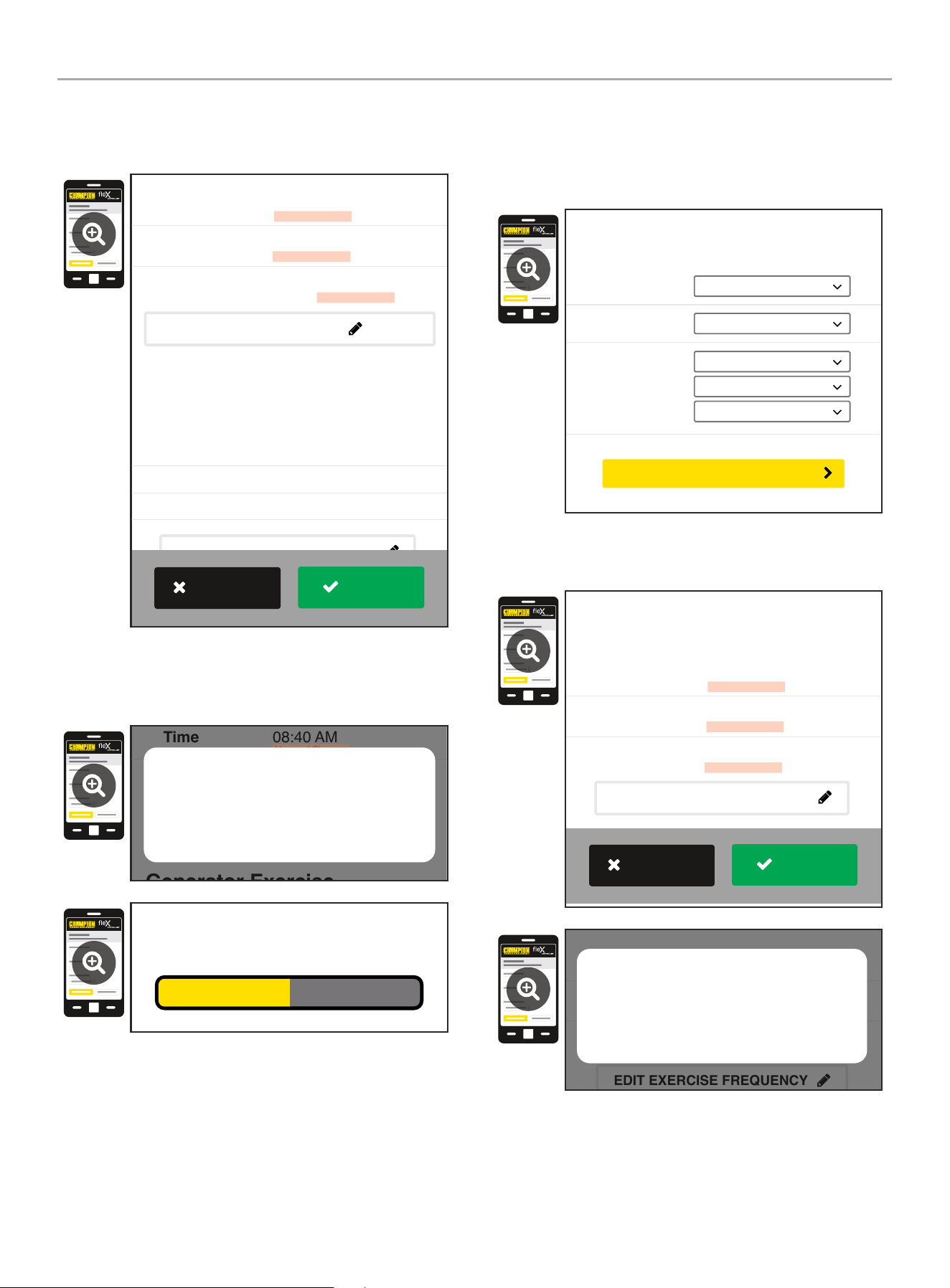
5. Confirm and apply the settings before continuing. If you do
not apply immediately, the clock will be later than actual.
Unsaved changes are highlighted.
Generator Exercise
Every Week
Friday
09:00 AM
Frequency:
Day:
Time:
March 22, 2022
08:40 AM
On
Date
Time
Day Light Saving
Generator Date and Time
EDIT DATE & TIME
(Automated Maintenance Running)
EDIT EXERCISE FREQUENCY
Unsaved Changes
Unsaved Changes
Unsaved Changes
APPLY
REVERT
6. Some operating systems will require additional steps to
confirm update, accept all pop-up windows until progress bar
is seen on screen.
Generator Exercise
Friday
09:00 AM
March 22, 2022
08:40 AM
On
Time
Day Light Saving
EDIT DATE & TIME
(Automated Maintenance Running)
Unsaved Changes
Unsaved Changes
Are your sure to save the changes?
Cancel OK
Saving...
7. Set the HSB exercise frequency and schedule.
OTE: N Exercise duration is system set at 15 minutes. The
duration is not adjustable. The fleX Controller
™
must be in
the AUTO mode in order to exercise.
Freq:
Day:
Time:
Choose Mode...
Choose Day...
Choose Hour...
Choose Minute...
Choose AM/PM...
Generator Exercise
(Automated Maintenance Running)
CONFIRM EXERCISE FREQUENCY
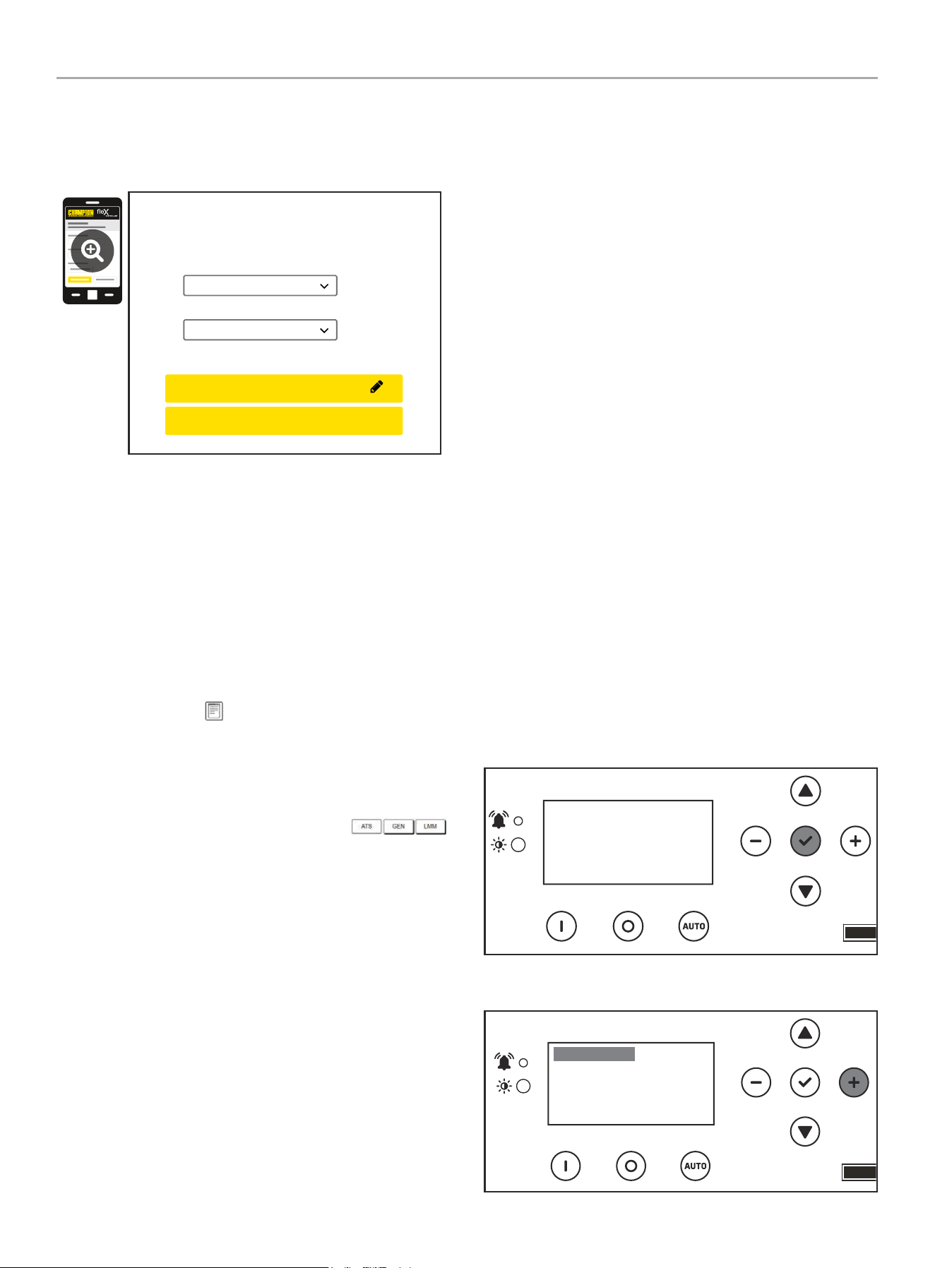
8. Confirm and apply the settings before continuing. Unsaved
changes are highlighted.
Every Week
Thursday
01:00 PM
Frequency
Day
Time
Unsaved Changes
Unsaved Changes
Unsaved Changes
Generator Exercise
(Automated Maintenance Running)
EDIT EXERCISE FREQUENCY
APPLY
REVERT
Every Week
Thursday
01:00 PM
Frequency
Day
Time
Unsaved Changes
Unsaved Changes
Unsaved Changes
(Automated Maintenance Running)
EDIT EXERCISE FREQUENCY
Are your sure to save the changes?
Cancel OK
WHOLE HOUSE AUTOMATIC TRANSFER SWITCH - ALL fleX CONTROLLER™
MODELS
INSTALLATION
22
9. Wireless network settings are not used at this time. The
default values (shown below) should not be adjusted.
Adjustment of this factory settings will require a certified
electrician to correct.
Wireless Network
Internet Service:
Web Page Mode:
Direct Connect
AP Mode
CONFIRM NETWORK SETTINGS
CANCEL SETTINGS
AP Mode IP : 192. 168. 0. 90
10. The time, date, and exercise information have now been
setup for the fleX ATS and HSB. You can close your browser
and disconnect from the ATS Wi-Fi, or skip to step 2 in the
next section “ATS and HSB STATUS USING WI-FI”.
ATS and HSB Status Using WIFI
1. Using a WIFI enabled device, connect to the “Champion HSB”
WIFI network following steps 1, 2, and 3 from WIFI Setup
Method.
2. After loading the Home Standby Generator Settings page,
locate and click the icon at the bottom right corner of the
page.
3. You are now viewing the ATS and HSB status page. Items
such as voltage, frequency, current, etc. can all be viewed for
both utility and HSB power. All of the information is live. There
are three tabs located at the top of the page.
ATS, GEN, and LMM. Each tab will display the status for
the Transfer Switch, Home Standby Generator, or Load
Management Module(s) respectively.
4. When finished viewing the status of the ATS, Generator, and
LMM, close your browser and disconnect from the WIFI.
Connecting the Load Management Systems
The following instructions pertain only to fleX Controller
™
Load
Management Modules (LMM) that use Power Line Carrier (PLC)
communication. If one or more LMM’s are being installed on the
home, install them per the installation instructions included with
the LMM before continuing.
BOND MODE (SYSTEM LEARNING MODE)
There are three methodologies for connecting the fleX generator
(HSB), fleX automatic transfer switch (ATS) and fleX load
management module (LMM). One includes connecting a non-fleX
HSB to fleX ATS and LMM. Please note the options and follow
those instructions. Most common is option A.
A. Complete Champion system (HSB, 1 ATS, LMMs) – use this
method if installing 1 ATS with the system. All 3 or more are
part of the fleX system.
B. Complete Champion system (HSB, 2 ATS, LMMs) – use this
method if installing 2 ATS with the system. All 3 or more are
part of the fleX system.
C. Partial Champion system (non-fleX HSB, 1 ATS, LMMs)
– use this method if installing a non-fleX HSB with two-wire
start - only the ATS or LMMs or more are part of the fleX
system.
A two-wire connection here refers to a signal circuit that runs
between the fleX Controller
™
ATS and the non-fleX HSB. When
installed in this configuration, the non-fleX HSB will turn on and
off based on the signal it is receiving from the fleX ATS. The two-
wire signal from the fleX Controller
™
ATS is connected to 2-wire
(START) and COM (Ground) to a non-fleX HSB. Refer to wiring
diagram of the non-fleX HSB on how to create the circuit.
A. Complete Champion system (HSB, 1 ATS, LMMs)
1. Confirm the generator (HSB), automatic transfer switch (ATS)
and load management module (LMM) are wired correctly.
2. To begin programming, disable AUTO by pressing OFF.
The screen should show OFF, then press and hold OK for 3
seconds to enter SETTINGS.
OFF
00-00
00:00
ARRET
3. Click + until you reach USER SETTINGS.
.USER SETTINGS
NEXT SERVICE
RESET SERVICE
BROWNOUT DELAY
100.0h
30s
OFF
WHOLE HOUSE AUTOMATIC TRANSFER SWITCH - ALL fleX CONTROLLER™
MODELS
INSTALLATION
23
4. Scroll down until you reach BOND MODE is highlighted. Then
+ to move to the right. Then use a combination of up/down to
adjust ON or OFF. Set to ON.
.USER SETTINGS
BRIGHTNESS
BOND MODE
100%
ON
5. After BOND MODE is adjusted, the fleX Controller
™
will exit
and change to “OFF”.
OFF
00-00
00:00
ARRET
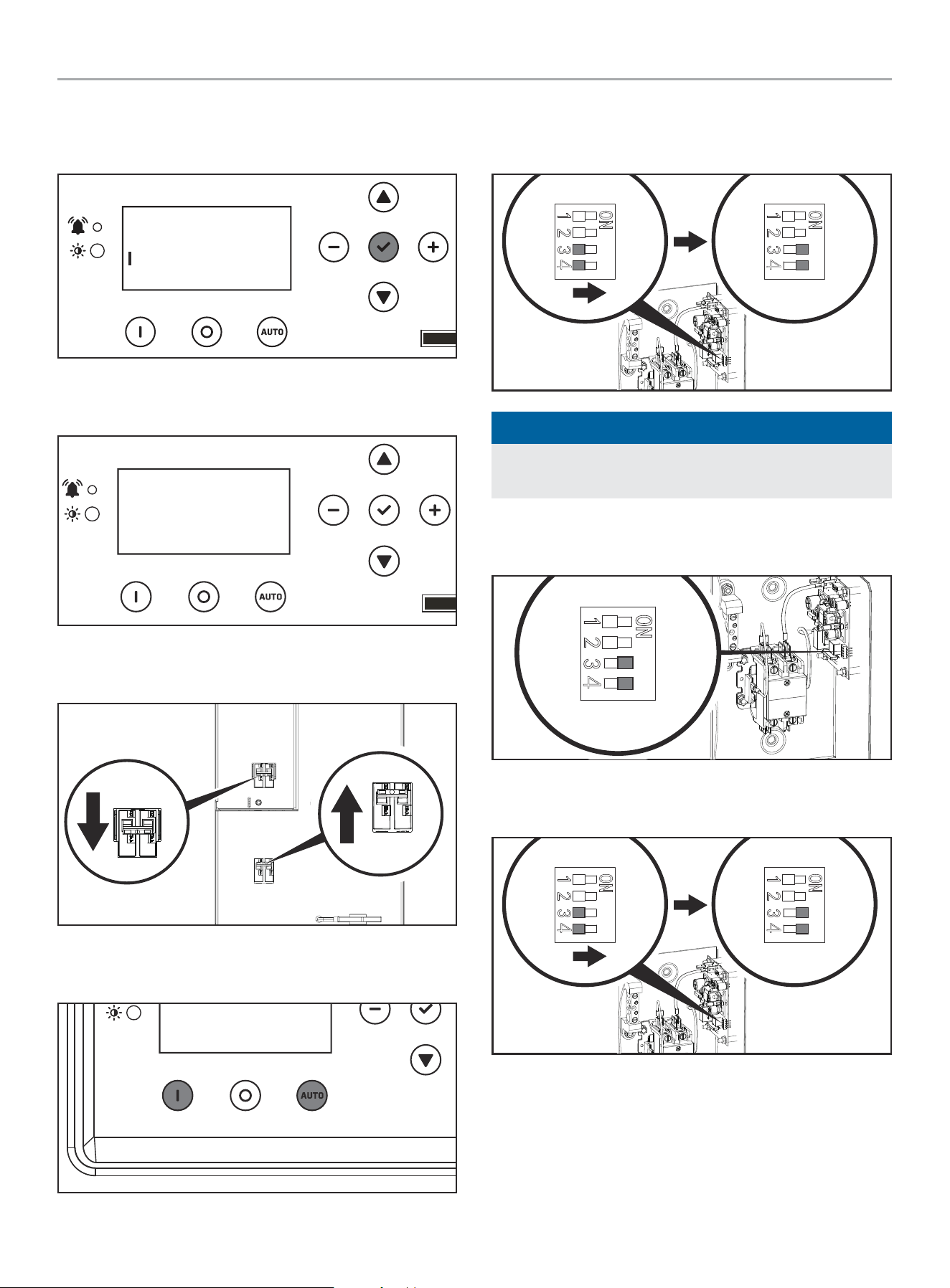
6. On the ATS, turn the utility breaker “OFF” and the generator
circuit breaker “ON”
Utility Service Disconnect
Desconexión del servicio publico
Déconnexion du service public
Generator
Generador
Génératrice
Generator
Generador
Génératrice
Utility Service Disconnect
Desconexión del servicio publico
Déconnexion du service public
7. Set the fleX Controller
™
in the MANUAL or AUTO mode. The
HSB will crank and start.
OFF
00-00
00:00
ARRET
8. After the ATS switches to generator power, and the LMMs are
powered by the generator, use a small flat head screwdriver
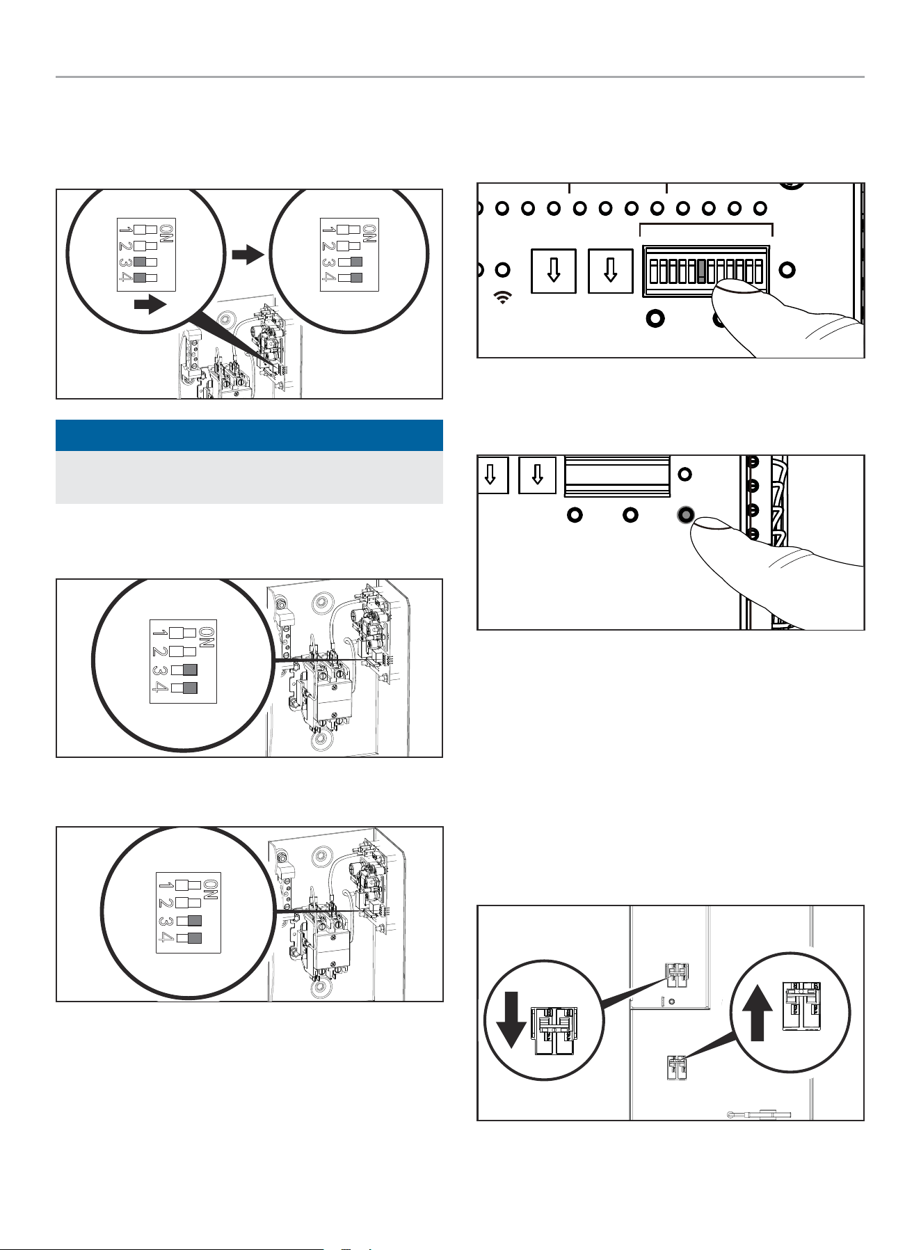
to adjust the LMM DIP switches 3 and 4 in “ON” position.
LINE / LIGNE
L2 L1
-PR
NOTICE
If the LMM DIP switches 3 and 4 are already in “ON” move the
to “OFF” for 1 second, then move back to “ON.”
9. At this point, the LMM is now in BOND MODE and ready to
bond to the ATS.
LINE / LIGNE
L2
T2 T1
L1
LOAD / CHARGE
5350-L-PR
10. If there are more than one LMM, move each DIP switch 3 and
4 to “ON.”
LINE / LIGNE
L2 L1
-PR
11. After the BOND MODE is activated, the Flex LMM will exit the
Bond Mode automatically, but the DIP switches 3 and 4 still
need to be moved to “OFF” manually.
WHOLE HOUSE AUTOMATIC TRANSFER SWITCH - ALL fleX CONTROLLER™
MODELS
INSTALLATION
24
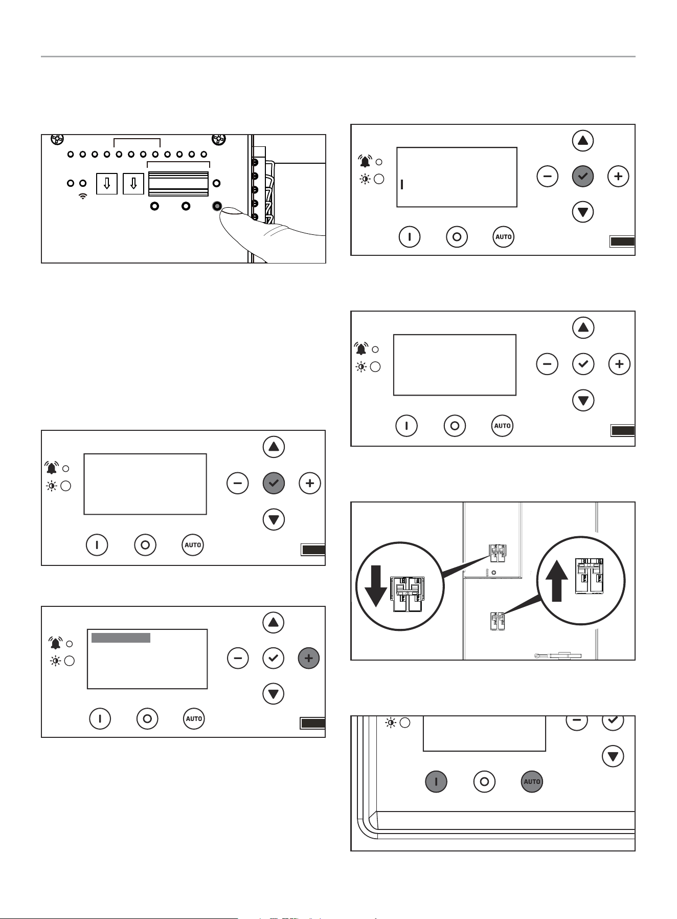
12. Press and hold “LEARN” button of ATS for about 8 seconds,
thereby entering SYSTEM LEARNING MODE. The ATS will
send its UUID code information to HSB and LMMs to bond
them together.
TEST
PRUEBA
TEST
kW x10 kW x1
DEFAULT
POR DEFECTO
DÉFAUT
LEARN
APRENDER
APPRENDRE
RESET
RESTABLECER
RÉINITIALISER
PMTUTILGENAC1AC2GSTAR TGSTOP
RUN
CORRER
MARCHE
WiFi
ATSPOS
1 2 3 4
LMM
ON / ENCENDIDO / MARCHE
OFF / APAGADO / ARRÊT
1 2 3 4 5 6 1211107 8 9
13. fleX Controller
™
LEDs will flash multiple times green red
indicated learn is complete. See CONFIRMING BOND MODE
section to verify.
B. Complete Champion system (HSB, 2 ATS, LMMs)
1. Confirm the generator (HSB), automatic transfer switch (ATS)
and load management module (LMM) are wired correctly.
2. To begin programming, disable AUTO by pressing OFF.
The screen should show OFF, then press and hold OK for 3
seconds to enter SETTINGS.
OFF
00-00
00:00
ARRET
3. Click + until you reach USER SETTINGS.
.USER SETTINGS
NEXT SERVICE
RESET SERVICE
BROWNOUT DELAY
100.0h
30s
OFF
4. Scroll down until you reach BOND MODE is highlighted. Then
+ to move to the right. Then use a combination of up/down to
adjust ON or OFF. Set to ON.
.USER SETTINGS
BRIGHTNESS
BOND MODE
100%
ON
5. After BOND MODE is adjusted, the fleX Controller
™
will exit
and change to “OFF”.
OFF
00-00
00:00
ARRET
6. On the ATS, turn the utility breaker “OFF” and the generator
circuit breaker “ON”
Utility Service Disconnect
Desconexión del servicio publico
Déconnexion du service public
Generator
Generador
Génératrice
Generator
Generador
Génératrice
Utility Service Disconnect
Desconexión del servicio publico
Déconnexion du service public
7. Set the fleX Controller
™
in the MANUAL or AUTO mode. The
HSB will crank and start.
OFF
00-00
00:00
ARRET
WHOLE HOUSE AUTOMATIC TRANSFER SWITCH - ALL fleX CONTROLLER™
MODELS
INSTALLATION
25
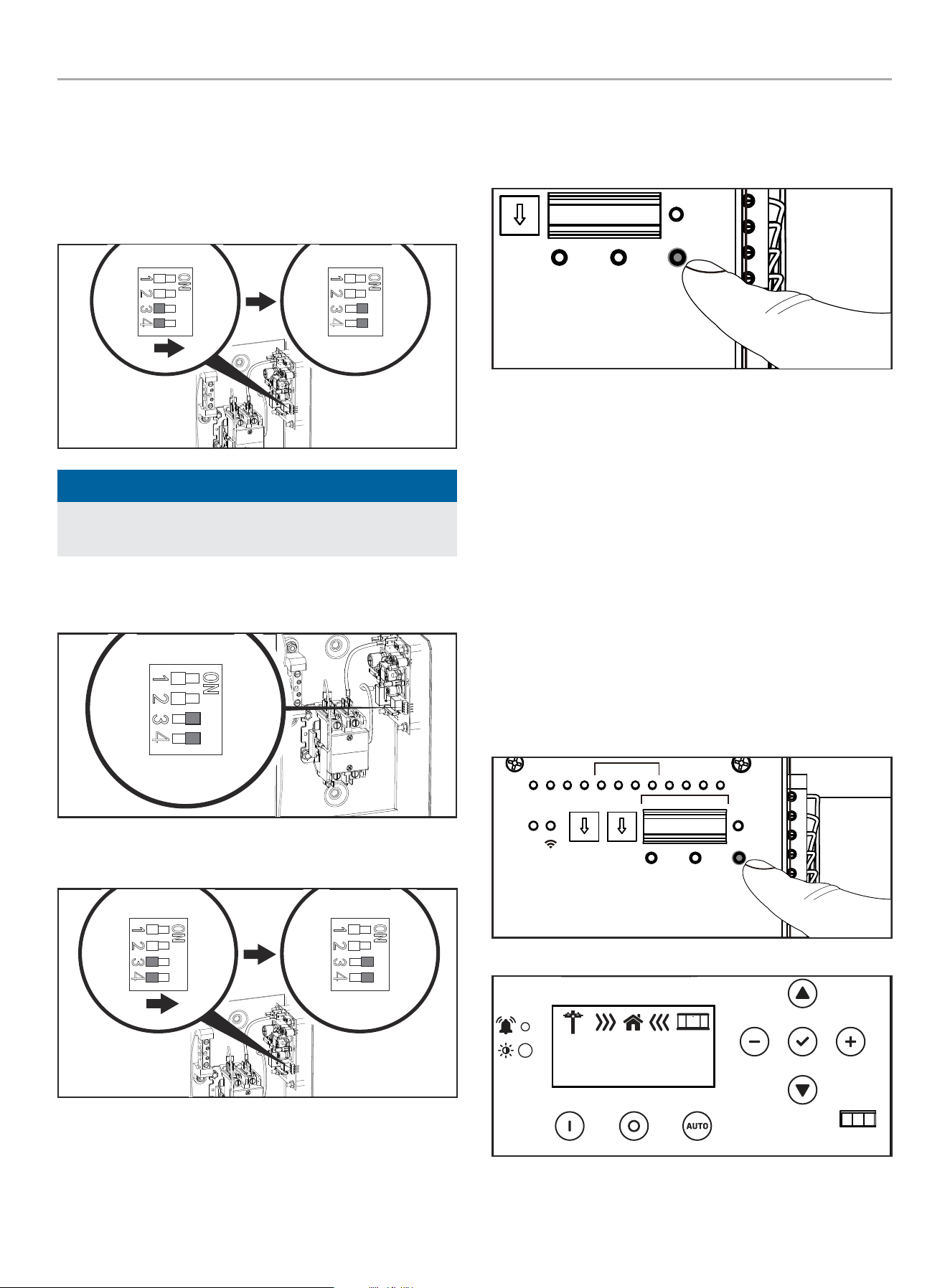
8. After BOTH (primary and secondary) ATS switch to generator
power, and the LMMs are powered by the generator, use a
small flat head screwdriver to adjust the LMM DIP switches 3
and 4 in “ON” position. Do this for all the LMMs in service.
LINE / LIGNE
L2 L1
-PR
NOTICE
If the LMM DIP switches 3 and 4 are already in “ON” move the
to “OFF” for 1 second, then move back to “ON.”
9. At this point, the LMM is now in BOND MODE and ready to
bond to the ATS.
LINE / LIGNE
L2
T2 T1
L1
LOAD / CHARGE
5350-L-PR
10. If there are more than one LMM, move each DIP switch 3 and
4 to “ON.”
LINE / LIGNE
L2
T2 T1
L1
LOAD / CHARGE
5350-L-PR
11. After the BOND MODE is activated, the Flex LMM will exit the
Bond Mode automatically, but the DIP switches 3 and 4 still
need to be moved to “OFF” manually.
12. Adjust the secondary ATS DIP switches 6 to “ON.” If DIP
switch 6 is already “ON,” move the to “OFF” for 1 second,
then move back to “ON.” The secondary ATS is now in BOND
MODE, and ready to be bonded to the primary ATS.
TEST
PRUEBA
kW x10 kW x1
DEFAULT
POR DEFECTO
LEARN
APRENDER
RESET
RESTABLECER
RÉINITIALISER
PMTUTILGENAC1AC2GSTARTTOP
RER
RCHE
WiFi
ATSPOS
1 2 3 4
ON / ENCENDIDO / MARCHE
OFF / APAGADO / ARRÊT
1 2 3 4 5 6 1211107 8 9
ON
1 2 3 4 5 6 7 8 9 10 11 12
13. Press and hold “LEARN” button of the primary ATS for about
8 seconds, thereby entering SYSTEM LEARNING MODE. The
ATS will send its UUID code information to HSB and LMMs to
bond them together.
TEST
PRUEBA
TEST
kW x10 kW x1
DEFAULT
POR DEFECTO
DÉFAUT
LEARN
APRENDER
APPRENDRE
RÉINITIALISER
14. fleX Controller
™
LEDs will flash multiple times green red
indicated learn is complete. See CONFIRMING BOND MODE
section to verify.
C. Partial Champion system (non-fleX HSB, 1 ATS, LMMs)
1. Confirm the non-fleX generator (HSB), automatic transfer
switch (ATS) and load management module (LMM) are wired
correctly.
2. Power on the non-fleX HSB controller and put in STOP mode.
See HSB instruction manual for more details.
3. On the fleX ATS, turn the utility breaker “OFF” and the
generator circuit breaker “ON”
Utility Service Disconnect
Desconexión del servicio publico
Déconnexion du service public
Generator
Generador
Génératrice
Generator
Generador
Génératrice
Utility Service Disconnect
Desconexión del servicio publico
Déconnexion du service public
WHOLE HOUSE AUTOMATIC TRANSFER SWITCH - ALL fleX CONTROLLER™
MODELS
INSTALLATION
26
4. Set the non-fleX HSB controller in the MANUAL or AUTO
mode. The HSB will crank and start. See HSB instruction
manual for more details.
5. Until the ATS switches to generator power, and the LMMs are
powered by the generator, use a small flat head screwdriver
to adjust the LMM DIP switches 3 and 4 in “ON” position.
LINE / LIGNE
L2 L1
LOAD / CHARGE
5350-L-PR
NOTICE
If the LMM DIP switches 3 and 4 are already in “ON” move the
to “OFF” for 1 second, then move back to “ON.”
6. At this point, the LMM is now in BOND MODE and ready to
bond to the ATS.
LINE / LIGNE
L2
T2 T1
L1
LOAD / CHARGE
5350-L-PR
7. If there are more than one LMM, move each DIP switch 3 and
4 to “ON.”
LINE / LIGNE
L2 L1
PR
8. After the BOND MODE is activated, the Flex LMM will exit the
Bond Mode automatically, but the DIP switches 3 and 4 still
need to be moved to “OFF” manually.
9. Press and hold “LEARN” button of ATS for about 8 seconds,
thereby entering SYSTEM LEARNING MODE. The ATS will
send its UUID code information to HSB and LMMs to bond
them together.
TEST
PRUEBA
TEST
kW x1
DEFAULT
POR DEFECTO
DÉFAUT
LEARN
APRENDER
APPRENDRE
RÉINITIALISER
10. fleX Controller
™
LEDs will flash multiple times green red
indicated learn is complete. See CONFIRMING BOND MODE
section to verify.
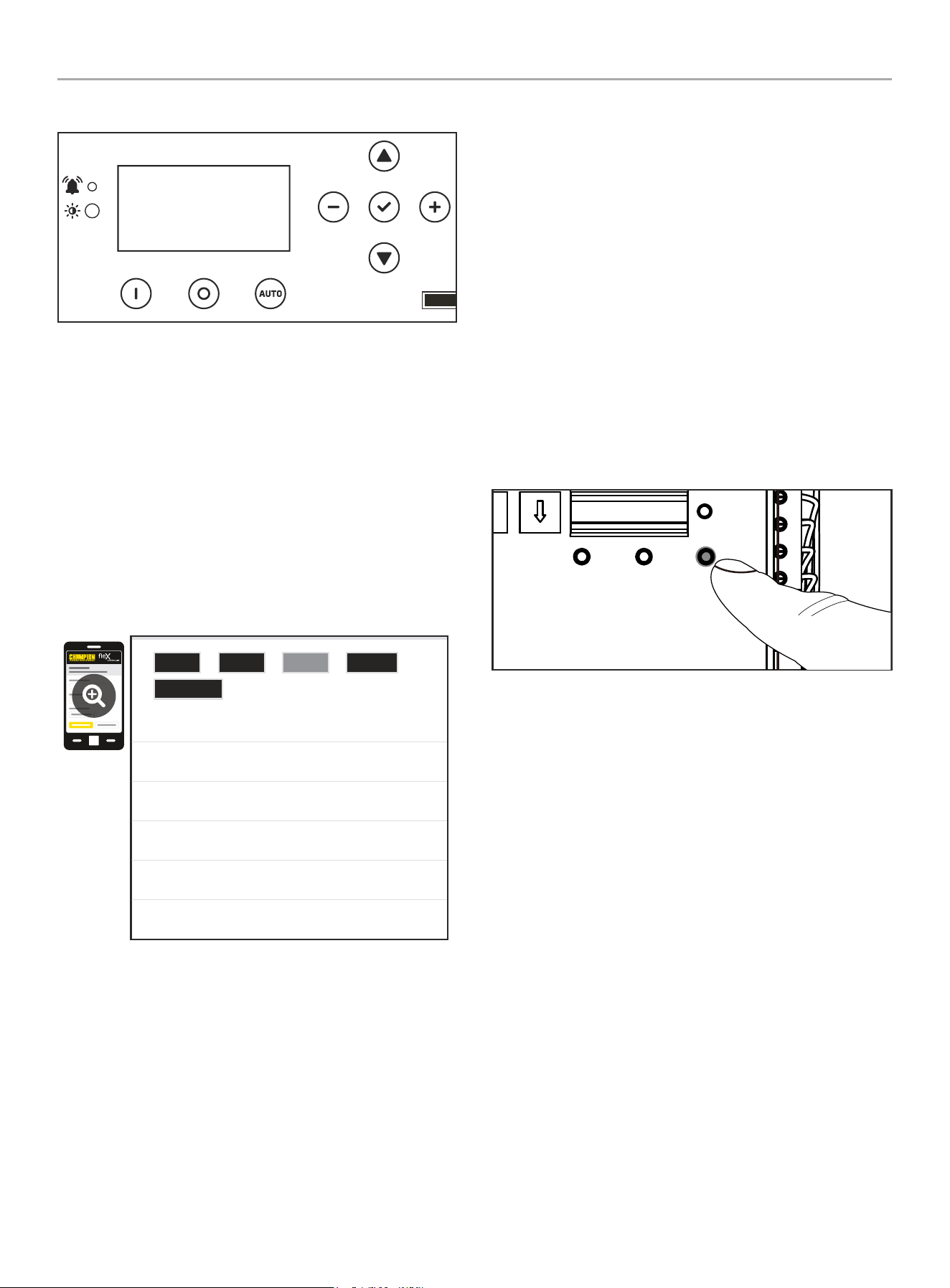
CONFIRMING BOND MODE
A. Complete Champion system (HSB, 1 ATS, LMMs) – check
BOND MODE per below.
B. Complete Champion system (HSB, 2 ATS, LMMs) – check
BOND MODE per below.
C. Partial Champion system (non-fleX HSB, 1 ATS, LMMs) –
unable to check BOND MODE.
1. As soon as you Press and hold “LEARN” button of ATS for
about 8 seconds, thereby entering SYSTEM LEARNING MODE,
the HSB fleX Controller will display power direction icons. If
BOND MODE was not successful, the HSB fleX Controller
™
will remain OFF.
TEST
PRUEBA
TEST
kW x10 kW x1
DEFAULT
POR DEFECTO
DÉFAUT
LEARN
APRENDER
APPRENDRE
RESET
RESTABLECER
RÉINITIALISER
PMTUTILGENAC1AC2GSTAR TGSTOP
RUN
CORRER
MARCHE
WiFi
ATSPOS
1 2 3 4
LMM
ON / ENCENDIDO / MARCHE
OFF / APAGADO / ARRÊT
1 2 3 4 5 6 1211107 8 9
Successful BOND
OFF
ARRET
240.0V
60.0HZ
WHOLE HOUSE AUTOMATIC TRANSFER SWITCH - ALL fleX CONTROLLER™
MODELS
INSTALLATION
27
Unsuccessful BOND
OFF
ARRET
2. Alternatively, you can confirm through Wi-Fi provided the
ATS is connected per “Wi-Fi Setup Method” in this manual.
Once you have confirmed the ATS is connected to Wi-Fi, and
you have successfully negotiated setup, search and connect
to network name (SSID) “Champion ####” where #### will
match the last four digits of the serial number that is printed
on the control board. After connecting to Wi-Fi, open your
device’s web browser. In the browser address change the
address to 192.168.0.90 and begin search. This will direct
your browser to the Champion fleX Controller
™
Home Standby
Generator Settings page located on the ATS.
Navigate to the LMM page and you will note each LMM registers 0
kW as shown
0.00kW
0.00kW
0.00kW
0.00kW
0.00kW
0.00kW
LMM Relay0 Demand:
LMM Relay1 Demand:
LMM Relay0 Demand:
LMM Relay3 Demand:
Load AC1 Demand:
Load AC2 Demand:
ATS
Revision
GEN LMM Event
LOAD TEACHING SYSTEM
After installation and wiring are complete teach the ATS which
loads are attached by the following procedure. Teaching the
system is only required if 1 or more LMM’s were installed OR if
AC1 OR if AC2 is being used to manage loads.
1. Turn fleX Controller
™
ATS UTILITY circuit breaker to the OFF
position. Generator will start and run automatically.
2. Confirm managed loads are all operating.
3. Press and hold the button marked “LEARN” for 8 seconds.
ATS will turn off all loads, and then turn on one load at a
time until all loads are turned on. Then, the ATS will shutoff
all managed loads one at a time until all are OFF. The ATS
will flash LEDs indicating function in process. LMM1-LMM4
LEDs are separated by about 15 seconds. A green flashing
light indicates learning was successful. A red flashing light
indicates an overload has occurred.
4. After ATS has learned all loads the LMM units will be returned
to normal operation.
5. Installation configuration is now held in memory and will not
be affected by power outage.
6. Return UTILITY circuit breaker to the ON position. ATS will
transfer load back to utility and generator will cool down and
shut off.
7. Repeat this process if LMM units are added or removed from
the system.
TEST
PRUEBA
TEST
x10 kW x1
DEFAULT
POR DEFECTO
DÉFAUT
LEARN
APRENDER
APPRENDRE
RÉINITIALISER
Full System Check
1. Please ensure BOND MODE has been completed before final
system check.
2. Open Utility breaker for full system test, close breaker after
confirming all systems working.
3. After Utility breaker opens engine will start automatically.
4. fleX ATS will reboot on Generator power and control switching
of latching relays.
5. Home is now powered by Generator. If Load Management
modules (LMM) have been installed, please allow 5 minutes
for LMM and AC1/AC2 to become active.
6. Perform Load Learning through ATS panel at this time. LMM
units will be dropped and reacquired in order.
7. Close Utility breaker. The ATS will transfer back to Utility and
Generator will begin shutdown cycle.
8. System is now fully functional.
9. Put the fleX Controller
™
to the previous position (either
MANUAL or AUTO for example). Confirm utility power is
active, utility side relay is closed, and home is receiving
power.

WHOLE HOUSE AUTOMATIC TRANSFER SWITCH - ALL fleX CONTROLLER™
MODELS
INSTALLATION
28
10. Return to HSB and verify the controller is in “AUTO” mode.
Confirm icons indicate Utility power is active, Utility side relay
is closed, and home is receiving power.
11. Close and lock HSB hoods return keys to customer.
NEMA 1 – This type of enclosed ATS is for indoor installations
only.
NEMA 3R – This type of enclosed ATS is similar to the indoor box,
except that it is a weatherproof enclosure and required for exterior
installations by code. The enclosure only has knockouts on the
bottom side for the enclosure, requires water tight fasteners/
grommets when installed outside per code. This enclosure can
also be used inside.
WHOLE HOUSE AUTOMATIC TRANSFER SWITCH - ALL fleX CONTROLLER™
MODELS
SPECIFICATIONS
29
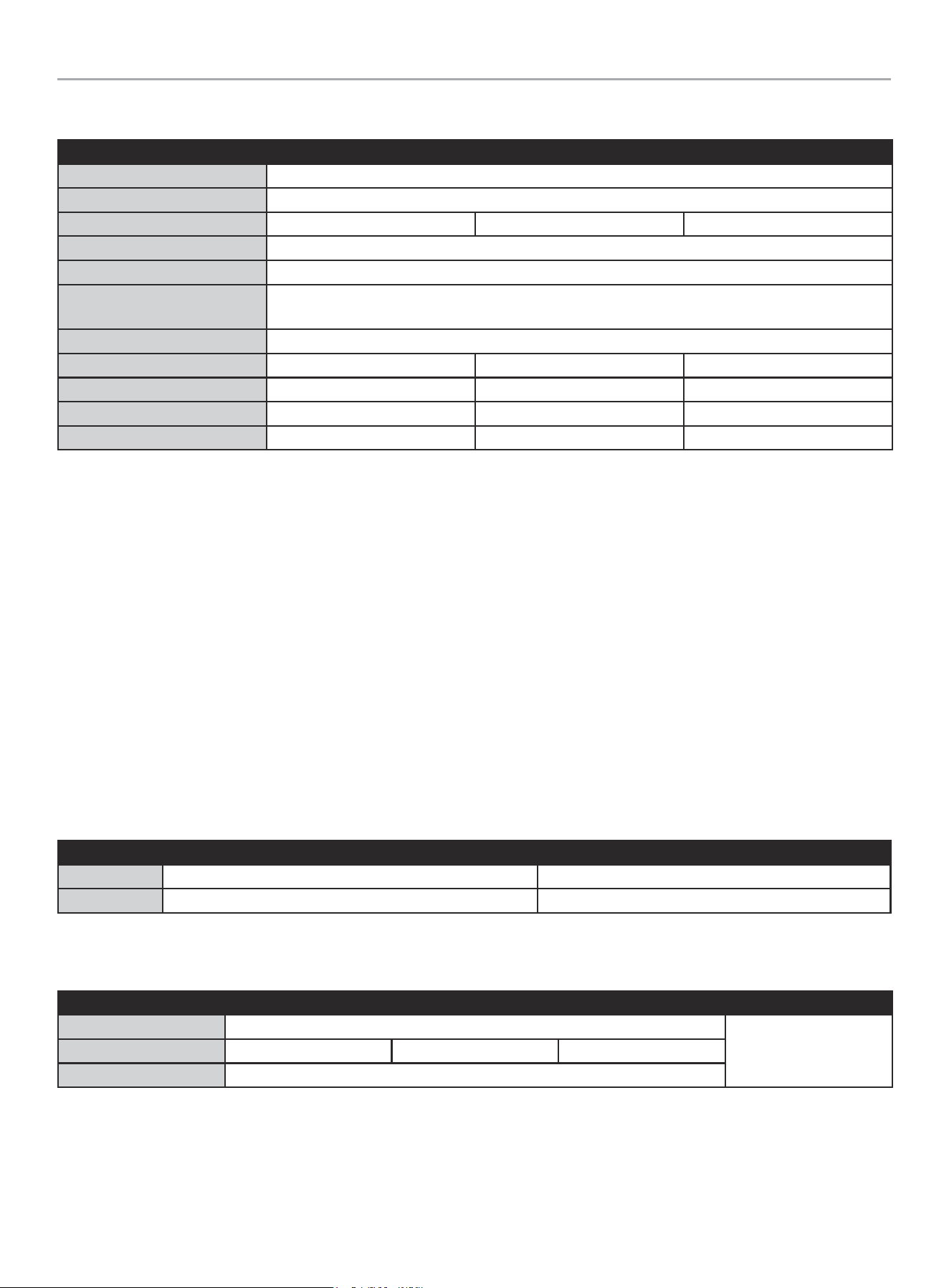
SPECIFICATIONS
Model 201020 201355 201039
Service Rating Service Entry Rating
Enclosure Style Type 3R Outdoor*
Maximum Amps 100 150 200
Nominal Volts 120/240
Transition Type Open transition, break before make
ETL Listed - Conforms to CSA Std. C22.2 NO. 100
UL Std. NO. 1008
Load Management Circuits 4
Length 28 in. (71.2 cm) 28 in. (71.2 cm) 28 in. (71.2 cm)
Width 18.7 in. (47.5 cm) 18.7 in. (47.5 cm) 18.7 in. (47.5 cm)
Height 7.9 in. (20 cm) 7.9 in. (20 cm) 7.9 in. (20 cm)
Weight 53 lb. (24 kg) 53 lb. (24.1 kg) 53 lb. (24.1 kg)
Technical Specifications
– 22kAIC, no short-time current rating.
– Suitable for use in accordance with Article 702 of the National Electric Code, NFPA 70.
– Suitable for use as service equipment NORMAL source only. Additional disconnect must be readily available for the alternate source
unless the alternate source is an accessible generator and can be readily shut down.
– Suitable for control of motors, electrical discharge lamps, tungsten filament lamps, and electrical heating equipment where the sum of
the motor full load ampere rating and the ampere rating of other loads does not exceed the ampere rating of the switch. Tungsten load
not to exceed 30% of the switch rating.
– Continuous load not to exceed 80% of switch rating.
– Wiring to generator must be enclosed in conduit.
Short-circuit withstand and closing ratings
– This transfer switch is suitable for use in a circuit capable of delivering the short circuit for the maximum voltage as marked below:
Short-Circuit current (RMS symmetrical amps X 1000) Volts (Volts AC maximum)
Utility 22 240
Generator 10 240
Wire - Lug Rating - Torque
Load Neutral Ground Utility
AWG (gauge) min 1 – max 000
See circuit breaker
markings.
Lug Rating 250-14 AL9CU 350-6 AL9CU 1/0-14 AL9CU
Torque (lbf-in/Nm) 275 / 31
NEMA 3R – This type of enclosed ATS is a weatherproof enclosure and required for exterior installations by code. The enclosure has
knockouts on the bottom and side, and requires water tight connections when installed outside per code. This enclosure can also be used
inside.
WHOLE HOUSE AUTOMATIC TRANSFER SWITCH - ALL fleX CONTROLLER™
MODELS
SPECIFICATIONS
30
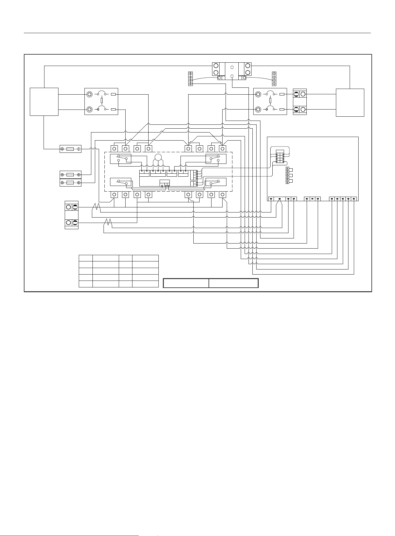
201020 ATS Wiring Diagram
Charger L
Generator
Supply
Utility
Supply
U-N
U-L1
U-L2
G-N
G-L1
G-L2
Generator Circuit Breaker Utility Circuit Breaker
Ground Bar Ground Bar
Neutral Bar
GN/YE
600Vac KTK-10
Fuse
Battery Charger
BN
600Vac KTK-10
Fuse
RD
BK
Utility Sense
Load
L2
L1
RD/BK RD
RD
BK
WH
RD
GN/YE
CT2-
CT2+
CT1-
CT1+
RD
RD/BK
RD
GN/YE
BU
OG
GND
L1
L2
U-L1
U-L2
N
G-L2
G-L1
RD
BK
WH
GY
YE
fleX Controller
2 Wire
AC1
AC2
RD Red
BK
Black
YE
Yellow
BN
Brown
BU
Blue
WH
White
GY
Grey OG Orange
GN/YE Green/Yellow
GN/YE
Red/Black
RD/BK
RD/BK
CT2+
M
NC_B
NO_B
C_B C_A
NC_A
NO_A
K3
C3 C4
K4
GY
BK
RD
L
VH1
N
G
V
R
J3
T
K4
VH5
C3&C4
K3
NC_A C_A
VH3
NO_B NO_A
VH7
C_B NC_B
VH4
CCW CW
VH2
N
L
G
R T
V
N
H1
RD
BK
BN
OG
GY
RD
YE
GY
GY
BU
BU
BK
BK
RD
YE
GY
BKRD
BK
GY
RD
YE
CT1- & CT2-
CT1+
GND
U-L1
U-L2
N
G-L2
G-L1
RD/BK
L1
L2
Open Transition Break Before Make

WHOLE HOUSE AUTOMATIC TRANSFER SWITCH - ALL fleX CONTROLLER™
MODELS
SPECIFICATIONS
31
201039 ATS Wiring Diagram
Charger L
Generator
Supply
Utility
Supply
U-N
U-L1
U-L2
G-N
G-L1
G-L2
Generator Circuit Breaker Utility Circuit Breaker
Ground Bar Ground Bar
Neutral Bar
GN/YE
600Vac KTK-10
Fuse
Battery Charger
BN
600Vac KTK-10
Fuse
RD
BK
Utility Sense
Load
L2
L1
RD/BK RD
RD RD/BK
WH
GN/YE
CT2-
CT2+
CT1-
CT1+
GND
L1
L2
U-L1
U-L2
N
G-L2
G-L1
fleX Controller
RD Red
BK
Black
YE
Yellow
BN
Brown
BU
Blue
WH
White
GY
Grey OG Orange
GN/YE Green/Yellow
GN/YE
Red/Black
RD/BK
M
NC_B
NO_B
C_B C_A
NC_A
NO_A
K3
C3 C4
K4
GY
BK
RD
L
VH1
N
G
V
R
J3
T
K4
VH5
C3&C4
K3
NC_A C_A
VH3
NO_B NO_A
VH7
C_B NC_B
VH4
CCW CW
VH2
N
L
G
R T
V
N
H1
RD
BK
BN
OG
GY
RD
YE
GY
GY
BU
BU
BK
BK
RD
YE
GY
BKRD
BK
GY
RD
YE
RD
RD/BK
RD
GN/YE
BU
OG
RD
BK
WH
GY
YE
2 Wire
AC1
AC2
CT2+
CT1- & CT2-
CT1+
GND
U-L1
U-L2
N
G-L2
G-L1
RD/BK
L1
L2
Open Transition Break Before Make
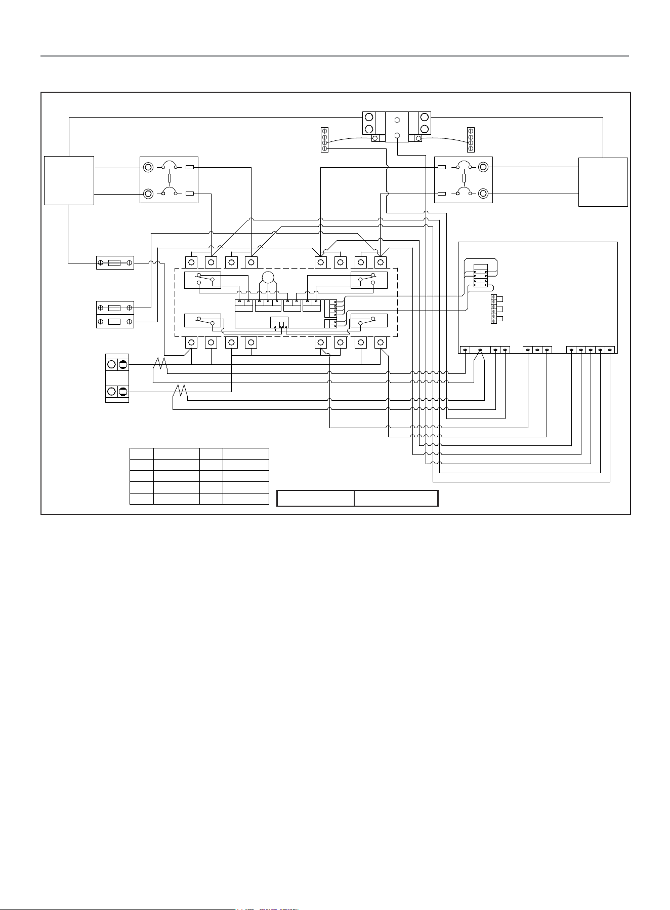
WHOLE HOUSE AUTOMATIC TRANSFER SWITCH - ALL fleX CONTROLLER™
MODELS
SPECIFICATIONS
32
201355 ATS Wiring Diagram
Charger L
Generator
Supply
Utility
Supply
U-N
U-L1
U-L2
G-N
G-L1
G-L2
Generator Circuit Breaker Utility Circuit Breaker
Ground Bar Ground Bar
Neutral Bar
GN/YE
600Vac KTK-10
Fuse
Battery Charger
BN
600Vac KTK-10
Fuse
RD
BK
Utility Sense
Load
L2
L1
RD/BK RD
RD RD/BK
WH
GN/YE
CT2-
CT2+
CT1-
CT1+
GND
L1
L2
U-L1
U-L2
N
G-L2
G-L1
fleX Controller
RD Red
BK
Black
YE
Yellow
BN
Brown
BU
Blue
WH
White
GY
Grey OG Orange
GN/YE Green/Yellow
GN/YE
Red/Black
RD/BK
M
NC_B
NO_B
C_B C_A
NC_A
NO_A
K3
C3 C4
K4
GY
BK
RD
L
VH1
N
G
V
R
J3
T
K4
VH5
C3&C4
K3
NC_A C_A
VH3
NO_B NO_A
VH7
C_B NC_B
VH4
CCW CW
VH2
N
L
G
R T
V
N
H1
RD
BK
BN
OG
GY
RD
YE
GY
GY
BU
BU
BK
BK
RD
YE
GY
BKRD
BK
GY
RD
YE
RD
RD/BK
RD
GN/YE
BU
OG
RD
BK
WH
GY
YE
2 Wire
AC1
AC2
CT2+
CT1- & CT2-
CT1+
GND
U-L1
U-L2
N
G-L2
G-L1
RD/BK
L1
L2
Open Transition Break Before Make

WHOLE HOUSE AUTOMATIC TRANSFER SWITCH - ALL fleX CONTROLLER™
MODELS
WARRANTY
33
WARRANTY
Each Champion transfer switch or accessory is guaranteed against mechanical or electrical failure due to manufacturing defects for a
period of 24 months following shipment from the factory. The manufacturer’s responsibility during this warranty period is limited to repair
or replacement, free of charge, of products proving defective under normal use or service when returned to the factory, transportation
charges prepaid. Guarantee is void on products that have been subjected to improper installation, misuse, alteration, abuse or unauthorized
repair. The manufacturer makes no warranty with respect to the fitness of any goods for a user’s particular application and assumes no
responsibility for proper selection and installation of its products. This warranty is in lieu of all other warranties, expressed or implied, and
limits the manufacturer’s liability for damages to the cost of the product. This warranty gives you specific legal rights, and you may have
other rights, which vary from state to state.

WARRANTY*
CHAMPION POWER EQUIPMENT
2 YEAR LIMITED WARRANTY
Warranty Qualifications
To register your product for warranty and FREE lifetime call center
technical support please visit:
https://www.championpowerequipment.com/register
To complete registration you will need to include a copy of the
purchase receipt as proof of original purchase. Proof of purchase
is required for warranty service. Please register within ten (10)
days from date of purchase.
Repair/Replacement Warranty
CPE warrants to the original purchaser that the mechanical and
electrical components will be free of defects in material and
workmanship for a period of two years (parts and labor) from
the original date of purchase and 180 days (parts and labor) for
commercial and industrial use. Transportation charges on product
submitted for repair or replacement under this warranty are the
sole responsibility of the purchaser. This warranty only applies to
the original purchaser and is not transferable.
Do Not Return The Unit To The Place Of
Purchase
Contact CPE’s Technical Service and CPE will troubleshoot any
issue via phone or e-mail. If the problem is not corrected by
this method, CPE will, at its option, authorize evaluation, repair
or replacement of the defective part or component at a CPE
Service Center. CPE will provide you with a case number for
warranty service. Please keep it for future reference. Repairs or
replacements without prior authorization, or at an unauthorized
repair facility, will not be covered by this warranty.
Warranty Exclusions
This warranty does not cover the following repairs and equipment:
Normal Wear
Products with mechanical and electrical components need
periodic parts and service to perform well. This warranty does not
cover repair when normal use has exhausted the life of a part or
the equipment as a whole.
Installation, Use and Maintenance
This warranty will not apply to parts and/or labor if the product is
deemed to have been misused, neglected, involved in an accident,
abused, loaded beyond the product’s limits, modified, installed
improperly or connected incorrectly to any electrical component.
Normal maintenance is not covered by this warranty and is not
required to be performed at a facility or by a person authorized by
CPE.
Other Exclusions
This warranty excludes:
– Cosmetic defects such as paint, decals, etc.
– Wear items such as filter elements, o-rings, etc.
– Accessory parts such as storage covers.
– Failures due to acts of God and other force majeure events
beyond the manufacturer’s control.
– Problems caused by parts that are not original Champion
Power Equipment parts.
Limits of Implied Warranty and
Consequential Damage
Champion Power Equipment disclaims any obligation to cover
any loss of time, use of this product, freight, or any incidental
or consequential claim by anyone from using this product. THIS
WARRANTY IS IN LIEU OF ALL OTHER WARRANTIES, EXPRESS
OR IMPLIED, INCLUDING WARRANTIES OF MERCHANTABILITY OR
FITNESS FOR A PARTICULAR PURPOSE.
A unit provided as an exchange will be subject to the warranty
of the original unit. The length of the warranty governing the
exchanged unit will remain calculated by reference to the purchase
date of the original unit.
This warranty gives you certain legal rights which may change
from state to state or province to province. Your state or province
may also have other rights you may be entitled to that are not
listed within this warranty.
Contact Information
Address
Champion Power Equipment, Inc.
6370 S Pioneer Way, Unit 101
Las Vegas, NV 89113 USA
www.championpowerequipment.com
Customer Service
Toll Free: 1-877-338-0999
info@championpowerequipment.com
Fax no.: 1-562-236-9429
Technical Service
Toll Free: 1-877-338-0999
tech@championpowerequipment.com
24/7 Tech Support: 1-562-204-1188