
INSTALLATION MANUAL
HOME STANDBY GENERATOR
Model 201202 (22 kW)
or visit championpowerequipment.com
SAVE THESE INSTRUCTIONS. This manual contains important safety precautions which should be read and understood before operating the product. Failure to do
so could result in serious injury. This manual should remain with the product.
Specifications, descriptions and illustrations in this manual are as accurate as known at the time of publication, but are subject to change without notice.
No part of this publication may be reproduced or used in any form by any means – graphic, electronic or mechanical, including photocopying, recording, taping or
information storage and retrieval systems – without the written permission of Champion Power Equipment (CPE).
Champion Power Equipment, Inc.
4655-M-OP REV 20250603
EN
ACTIVATE YOUR WARRANTY
by registering your product:
championpowerequipment.com

Have questions or need assistance?
Do not return this product to the store!
WE ARE HERE TO HELP!
Visit our website:
www.championpowerequipment.com
for more info:
Product Info & Updates
Frequently Asked Questions
– or –
Call our Customer Care Team Toll-Free at:
1-877-338-0999
Tech Bulletins
Product Registration
* We are always working to improve our products. Therefore, the enclosed product may differ slightly from the image on the cover.

HOME STANDBY GENERATOR- ALL fleX CONTROLLER™ MODELS
TABLE OF CONTENTS
3
TABLE OF CONTENTS
Introduction
................................................... 4
Home Standby Generator
...............................4
Parts Included ..................................................... 4
Tools Included ..................................................... 4
Safety ............................................................5
Safety Definitions ................................................. 5
Important Safety Instructions .......................6
Carbon Monoxide Hazards ........................................ 6
Installation Hazards ............................................... 7
Before Starting .................................................... 7
Operation Hazards ................................................ 7
Accidental Starting ................................................ 8
Electrical Shock Hazards ......................................... 8
Fuel Safety ........................................................ 8
Burn Hazards ...................................................... 9
Entanglement Hazards ............................................ 9
Battery Hazards ................................................... 9
Safety Symbols ................................................... 10
Safety Labels and Hang Tags ....................... 12
Safety label and Hang Tag locations ............................ 14
General Information ..................................... 15
Component Identification - Home Standby (HSB) Generator ... 15
Specifications .................................................... 16
Engine Torque Specifications .................................... 17
Master Mixing Assembly Jets (Carburetor System)............. 17
Alternator Overview .............................................. 18
Unpacking .................................................... 19
Installation
..................................................20
Placement & Installation Guidelines for Champion
Home Standby Generators to Reduce the Risk of Fire .......... 20
Intertek Group PLC Label ........................................ 21
Site Selection, Preparation and Placement ..................... 22
Installation Preparation .......................................... 25
Battery Charger .................................................. 33
Surge protection ................................................. 35
AVR / ASR = Automatic Voltage Regulator /
Speed Regulator (2 in 1)
.........................................36
Controls and Features
.................................37
AVR/ASR - Automatic Voltage Regulator / Electric Speed
Regulator (2 in 1) ................................................. 37
ATS Transfer Fuse ................................................ 37
Exterior Warning LED ............................................ 38
Generator ON/OFF Switch ....................................... 38
fleX Controller
™
................................................... 39
State .............................................................. 40
User Settings ..................................................... 41
Status Icons ...................................................... 43
Transfer Power Direction.........................................44
Information Icons ................................................. 44
Fault Icons ........................................................ 45
Fault Protection .................................................. 49
Fault Code Reset .................................................49
Wi-Fi Setup Method .............................................. 50
ATS and HSB Status Using WIFI ................................. 52
Programming fleX Controller
™
......................................
53
Setting System Time
............................................. 55
Setting Exercise Time ............................................55
Setting Brownout Delay ..........................................56
PIN Locations ..................................................... 56
Automatic Transfer Switch (ATS) ................................ 57
fleX Controller
™
Module .......................................... 57
ATS Installation ...........................................57
Bond Mode ....................................................... 57
Full System Check ............................................... 57
Commissioning the ATS .......................................... 58
HSB Test ..........................................................58
HSB Tests Under Load ........................................... 59
Checking Automatic Operation .................................. 60
Installing Standby Generator to non-fleX Controller
™
ATS ...... 60
Two-Wire Connection ............................................ 61
Customer Familiarization Summary ............................. 62
Maintenance ................................................62
201020 ATS Wiring Diagram
........................ 63
201039 ATS Wiring Diagram
........................ 64
201355 ATS Wiring Diagram
........................ 65
Troubleshooting HSB
...................................66
HSB, ATS Model & Serial Reference ATS Back-up Circuits .....68

HOME STANDBY GENERATOR- ALL fleX CONTROLLER™ MODELS
INTRODUCTION
4
HOME STANDBY GENERATOR
This home standby generator is intended exclusively for outdoor
installation. This generator will operate using either liquified
petroleum gas (LPG) or natural gas (NG).
This generator is designed to supply typical home load such as:
Induction motors – sump pumps, refrigerators, air conditioners,
furnaces
Electronic items – televisions, computers
Household lighting
Microwaves
This generator is not intended for use in critical life support
applications.
Proper sizing of the generator is required to ensure safe operation
of appliances. Some appliances require additional wattage to start
and must be considered in the sizing of the generator.
Parts Included
Your HSB ships with the following:
Operators Manual
Installation Manual
Flexible Fuel Line
HSB Enclosure Keys
Battery Series Cable
Master Mixer Assembly
Hurricane Pad Hardware
4 pieces - washer, Ø0.375-in USS
4 pieces - flange bolt, 0.375-16 x 2.00-in
Tools Included
Jet block tool for changing NG to LPG
4 mm allen wrench
Small back panel tool
5 mm allen wrench
INTRODUCTION
Congratulations on your purchase of a Champion Power Equipment
(CPE) product. CPE designs, builds, and supports all of our
products to strict specifications and guidelines. With proper
product knowledge, safe use, and regular maintenance, this
product should bring years of satisfying service.
Every effort has been made to ensure the accuracy and
completeness of the information in this manual at the time of
publication, and we reserve the right to change, alter and/or
improve the product and this document at any time without prior
notice.
CPE highly values how our products are designed, manufactured,
operated, and serviced as well as providing safety to the operator
and those around the generator. Therefore, it is IMPORTANT to
review this product manual and other product materials thoroughly
and be fully aware and knowledgeable of the assembly, operation,
dangers and maintenance of the product before use. Fully
familiarize yourself, and make sure others who plan on operating
the product fully familiarize themselves too, with the proper safety
and operation procedures before each use. Please always exercise
common sense and always err on the side of caution when
operating the product to ensure no accident, property damage,
or injury occurs. We want you to continue to use and be satisfied
with your CPE product for years to come.
When contacting CPE about parts and/or service, you will need to
supply the complete model and serial numbers of your product.
Transcribe the information found on your product’s nameplate
label to the table below
CPE TECHNICAL SUPPORT TEAM
1-877-338-0999
MODEL NUMBER
SERIAL NUMBER
DATE OF PURCHASE
PURCHASE LOCATION

HOME STANDBY GENERATOR- ALL fleX CONTROLLER™ MODELS
SAFETY
5
SAFETY
Safety Definitions
The purpose of safety symbols is to attract your attention to
possible dangers. The safety symbols, and their explanations,
deserve your careful attention and understanding. The safety
warnings do not by themselves eliminate any danger. The
instructions or warnings they give are not substitutes for proper
accident prevention measures.
DANGER
DANGER indicates a hazardous situation which, if not avoided,
will result in death or serious injury.
WARNING
WARNING indicates a hazardous situation which, if not
avoided, could result in death or serious injury.
CAUTION
CAUTION indicates a hazardous situation which, if not avoided,
could result in minor or moderate injury.
NOTICE
NOTICE indicates information considered important, but not
hazard-related (e.g., messages relating to property damage).
HOME STANDBY GENERATOR- ALL fleX CONTROLLER™ MODELS
IMPORTANT SAFETY INSTRUCTIONS
6
IMPORTANT SAFETY INSTRUCTIONS
WARNING
Cancer and Reproductive Harm – www.P65Warnings.ca.gov
Carbon Monoxide Hazards
DANGER
Generator exhaust contains carbon monoxide (CO), a colorless,
odorless, poisonous gas. Breathing carbon monoxide (CO) will
cause nausea, dizziness, fainting or death. If you start to feel
dizzy or weak, get to fresh air immediately.
GENERATOR MUST BE INSTALLED AND OPERATED
OUTDOORS ONLY.
Carbon monoxide (CO) poisoning symptoms include but are not
limited to the following:
– Lightheadedness, dizziness, blurred vision
– Physical fatigue, weakness in joints and muscles
– Mental fatigue, sleepiness, inability to concentrate or
speak clearly,
– Stomachache, vomiting, nausea
In the event of carbon monoxide (CO) poisoning:
– Seek fresh air immediately
– DO NOT sit, lie down or fall asleep.
– Alert others to the possibility of carbon monoxide (CO)
poisoning.
– If the affected person does not improve within minutes
of breathing fresh air, call 911 immediately for medical
assistance.
DANGER
Carbon Monoxide (CO) is a colorless, odorless, poisonous
gas. Breathing carbon monoxide will cause nausea, dizziness,
fainting or death.
Generator must be installed and operated outdoors only.
NEVER allow exhaust fumes to enter a confined area through
windows, doors, air intake vents or other openings of the
building.
ALWAYS avoid breathing exhaust fumes when near an
operating generator.
NEVER alter the generator or modify the exhaust system
thereby creating noncompliance with Federal and State
emissions regulations, local applicable codes, standards and
laws.
NEVER allow blockage of the engine’s air intake cooling
ventilation system. Doing so can seriously affect performance
and safe operation of the generator.
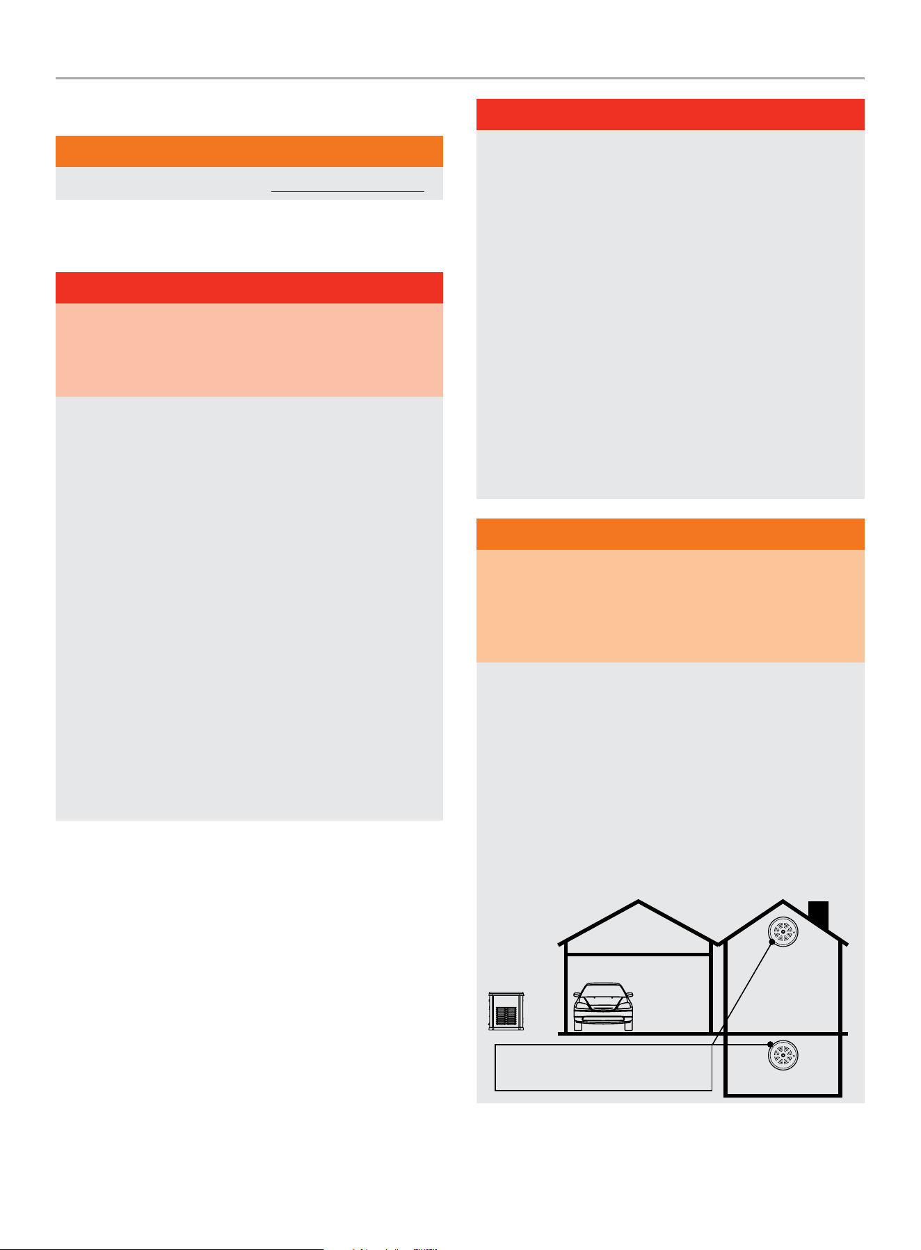
WARNING
Always install a battery-operated Carbon Monoxide (CO)
detector on each level of any building or home dwelling
adjacent to the generator location following the Carbon
Monoxide (CO) detector manufacturer’s installation
instructions.
In many U.S. States and Canadian Provinces, it is required by
law to have a Carbon Monoxide (CO) detector installed on each
level of an occupied building or home dwelling.
The Carbon Monoxide (CO) detector is a device that detects
elevated levels of poisonous Carbon Monoxide (CO) gas and
will alert the occupants by flashing a visual light indicator and
an audible alarm.
The Carbon Monoxide (CO) detector alarm will not sense
smoke, fire, or any other poisonous gas other than carbon
monoxide.
Carbon Monoxide (CO) detectors
located only in living spaces.

HOME STANDBY GENERATOR- ALL fleX CONTROLLER™ MODELS
IMPORTANT SAFETY INSTRUCTIONS
7
WARNING
Smoke alarms cannot detect Carbon Monoxide (CO) gas.
To better educate yourself about all carbon monoxide risks, go
to www.takeyourgeneratoroutside.com
WARNING
Do not use generator for medical life support uses.
In case of emergency, call 911 immediately.
NEVER use this product to power life support devices or life
support appliances.
Inform your electricity provider immediately if you or anyone in
your household depends on electrical equipment to live.
Inform your electrical provider immediately if a loss of power
would cause you or anyone in your household to experience a
medical emergency.
Installation Hazards
WARNING
Always have a qualified electrician or installation technician
who are familiar with applicable safety codes, standards and
regulations to install and service the generator.
ALWAYS comply with local, state and national electrical and
building codes when installing the generator.
NEVER alter the recommended installation in a way that would
render the unit non compliant with these codes.
ALWAYS comply with regulations that Occupational Safety and
Health Administration (OSHA) has established.
ALWAYS follow the generator manufacturer’s instructions.
Before Starting
WARNING
Before operation, read and understand the features and
controls of the generator, including the safety and maintenance
sections of this manual.
The owner/operator is responsible for all periodic maintenance.
Complete all scheduled maintenance in a timely manner.
Correct any issue before operating the generator.
The owner/operator is responsible for the safe operation of this
generator.
If any portion of this manual is not understood, contact
your Champion dealer for assistance before operating the
generator.
For service or parts assistance, contact your Champion dealer
if repairs are needed.
Operation Hazards
WARNING
ALWAYS operate the generator following the manufacturer’s
instructions. Operating the generator improperly or neglecting
maintenance can result in serious injury or possible death.
DO NOT allow children or unqualified persons to operate or
service the generator.
NEVER operate the generator with the covers open. Only
operate the generator with the covers closed and secured in
place.
NEVER leave the generator covers unlocked.
NEVER work on the generator when physically or mentally
fatigued. Remain alert at all times when working on the
generator.
NEVER operate the generator while under the influence of
alcohol or drugs.
NEVER climb or step on any part or components of the
generator. Doing so may result in personal injury and cause
damage to the exhaust system and/or create leakage to the
fuel system.

HOME STANDBY GENERATOR- ALL fleX CONTROLLER™ MODELS
IMPORTANT SAFETY INSTRUCTIONS
8
Accidental Starting
WARNING
ALWAYS prevent the generator from starting while the covers
are open. The generator may crank and start at any time
without notice. Follow these steps in order:
1. Pull fuse from fleX Controller
™
panel and secure with tape
to the panel.
2. Disconnect the NEGATIVE, NEG or (-) battery cable first,
and then remove the POSITIVE, POS or (+) battery cable.
To return the generator to service, follow these steps in order:
1. Connect the POSITIVE, POS or (+) battery cable first, and
then connect the NEGATIVE, NEG or (-) battery cable.
2. Remove taped fuse from the panel and reinstall into the
fleX Controller
™
.
Electrical Shock Hazards
WARNING
The generator produces dangerous voltage. Use extreme
caution when near the generator while it is operating.
Avoid contact with bare wires, terminals and connections while
the generator is operating.
ALWAYS stand on an insulated dry surface to reduce shock
hazard if work must be done on an operating generator.
NEVER wear jewelry that can conduct electricity when working
on the generator.
NEVER handle any kind of electrical device while hands or feet
are wet, while standing in water or while barefoot.
Proper earth grounding of the frame and external electrical
conductive components is required by the National Electrical
Code (NEC). State and local codes for proper grounding may
also apply.
Avoid direct contact with an electric shock victim. Immediately
shut down the source of electrical power. If this is not possible,
attempt to free the victim from the live conductor using a
nonconducting item such as a dry board or rope. If the victim
is unconscious, apply first aid and call 911 immediately.
Fuel Safety
DANGER
PROPANE AND NATURAL GAS ARE HIGHLY FLAMMABLE
AND EXPLOSIVE.
Fire or explosion can cause severe burns or death.
Propane/LPG (liquified petroleum gas) and LPG Vapors:
– LPG is a hydrocarbon gas that exists in a liquified form
and it’s vapors are highly flammable and explosive.
– LPG and it’s vapors are under pressure and can cause a
fire or explosion if ignited.
– LPG vapors are heavier than air and will settle in low
places while dissipating.
– LPG itself is odorless and tasteless. For safety, a chemical
is added to give it an odor to help detect leaks quickly.
– If a leak is detected, IMMEDIATELY turn OFF the gas
supply.
– In the event of an LPG fire and only when safe to do so,
first close the regulator valve OFF and then use a dry
powder extinguisher to put out the fire. This is because if
a fire is extinguished before the regulator valve is closed
OFF, then an explosion hazard condition could be created.
– Always keep the LPG cylinder in an upright position.
– LPG is a skin irritant and can cause severe cold burns
similar to frostbite.
– Always wear proper protective gloves when connecting to
and disconnecting from a propane bottle.
– Always keep LPG away from sparks, open flames, pilot
lights, heat and other sources of ignition.
DANGER
NG (natural gas) and NG Vapors:
– NG vapors are highly flammable and explosive.
– NG vapors can cause a fire or explosion if ignited.
– NG itself is odorless and tasteless. For safety, a chemical
is added to give it an odor to help detect leaks quickly.
– NG is lighter than air and will collect in higher areas.
– If a leak is detected, IMMEDIATELY turn OFF the gas
supply.
HOME STANDBY GENERATOR- ALL fleX CONTROLLER™ MODELS
IMPORTANT SAFETY INSTRUCTIONS
9
DANGER
NEVER allow any flames or smoke near the fuel system.
Wipe up any oil spills immediately.
NEVER allow any combustible materials to be near the
generator or to be left in the generator compartment.
ALWAYS keep the surrounding area near the generator clean
and free of debris.
Be sure to properly purge the fuel lines and leak-test according
to applicable codes before placing the generator in service.
Be sure to regularly inspect the fuel system for leaks. For
safety, a chemical is added to Propane/LPG/NG to give it an
odor to help detect leaks quickly. Never operate the generator
if a fuel leak is present.
Install a fire extinguisher near the generator. Keep it properly
charged and be familiar with its use. An ABC rated National
Fire Protection extinguisher is appropriate for use on standby
electric systems. Contact your local fire department with any
questions concerning the fire extinguisher.
DANGER
NEVER place a gasoline container, gasoline tank, LPG cylinder
or any combustible material in the path of the exhaust stream
during operation of the generator.
WARNING
Never use a remote or external fuel supply tank or flexible fuel
hose, or any other fuel component that is broken, cut, torn or
damaged.
Burn Hazards
WARNING
DO NOT touch hot surfaces.
ALWAYS avoid contact with hot exhaust components and
gases. Running engines produce heat. Severe burns can occur
on contact.
ALWAYS allow hot surfaces to cool to the touch.
Entanglement Hazards
WARNING
Use extreme caution when near rotating parts. Rotating parts
can entangle hands, feet, hair, clothing and/or accessories.
Traumatic amputation or severe laceration can result.
Keep hands and feet away from rotating parts.
Tie up long hair and remove jewelry.
Operate equipment with guards in place.
DO NOT wear loose-fitting clothing, dangling drawstrings or
items that could become caught.
Battery Hazards
WARNING
Always read and comply with the battery
manufacturer’s recommendations for
procedures concerning proper battery use
and maintenance.
Batteries contain sulfuric acid and generate
explosive mixtures of hydrogen and oxygen
gases. Keep any device that may cause
sparks or flames away from the battery to
prevent explosion.
Always wear protective glasses or goggles
and protective clothing when working
with batteries. Always follow the battery
manufacturer’s instructions on safety,
maintenance and installation procedures.
HOME STANDBY GENERATOR- ALL fleX CONTROLLER™ MODELS
IMPORTANT SAFETY INSTRUCTIONS
10
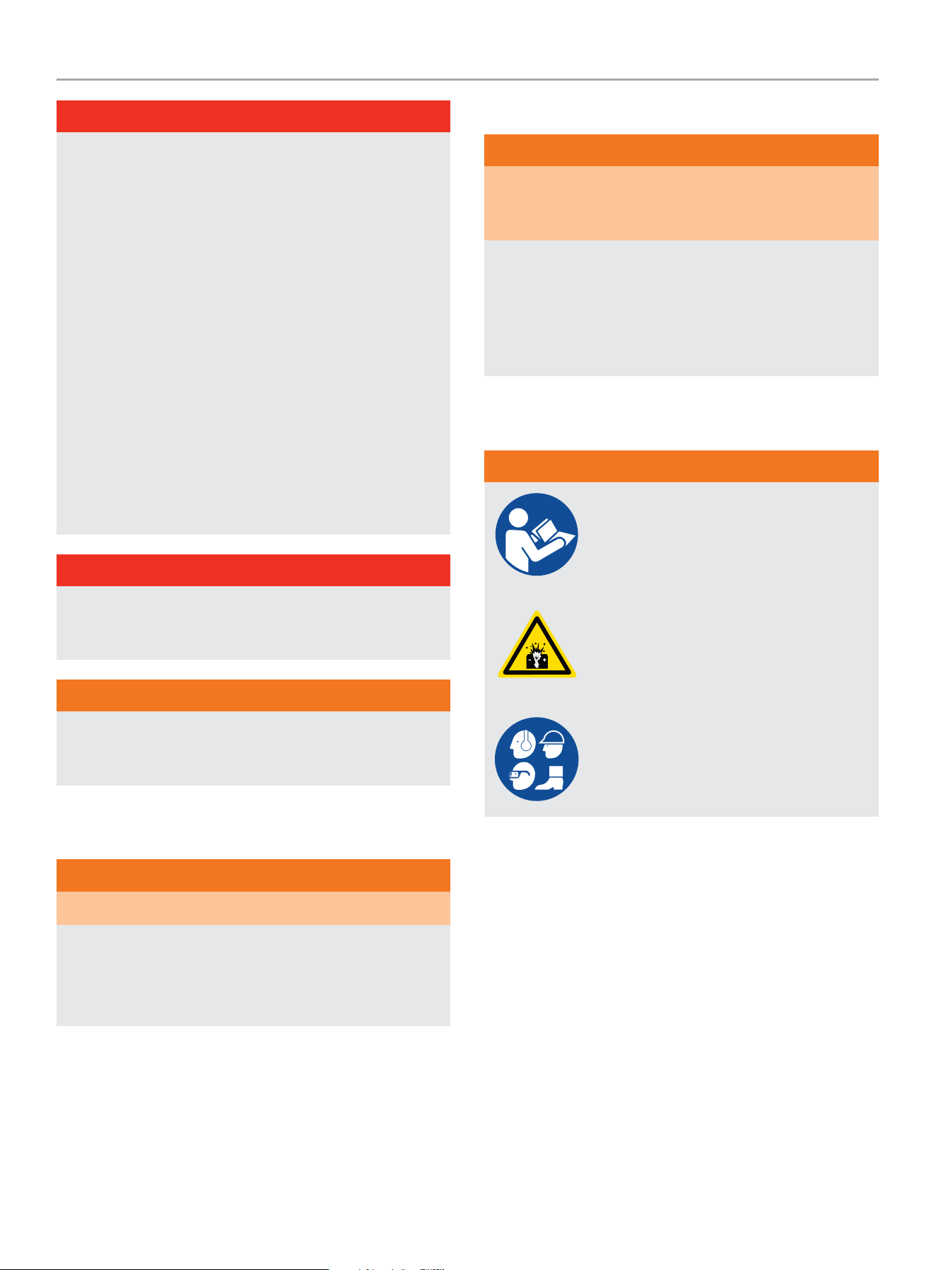
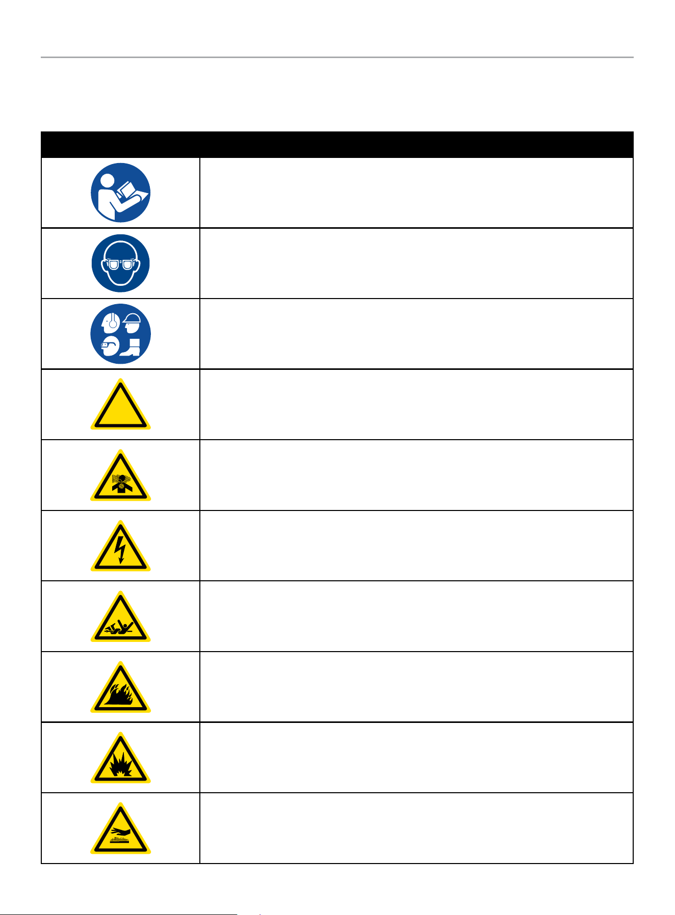
Safety Symbols
Some of the following symbols may be used on this product. Please study them and learn their meaning. Proper interpretation of these
symbols will allow you to more safely operate the product.
SYMBOL MEANING
Read Operator’s Manual. To reduce the risk of injury, user must read and understand operator’s
manual before using this product.
Eye protection. Always wear eye protection with side shields marked to comply with ANSI Z87.1
Wear personal protective equipment
!
Safety alert symbol
Asphyxiation hazard
Electrical shock hazard
Entanglement hazard
Fire hazard
Fire/Explosion. Fuel and its vapors are extremely flammable and explosive. Fire or explosion can
cause severe burns or death.
Hot Surface. To reduce the risk of injury or damage, avoid contact with any hot surface.
HOME STANDBY GENERATOR- ALL fleX CONTROLLER™ MODELS
IMPORTANT SAFETY INSTRUCTIONS
11
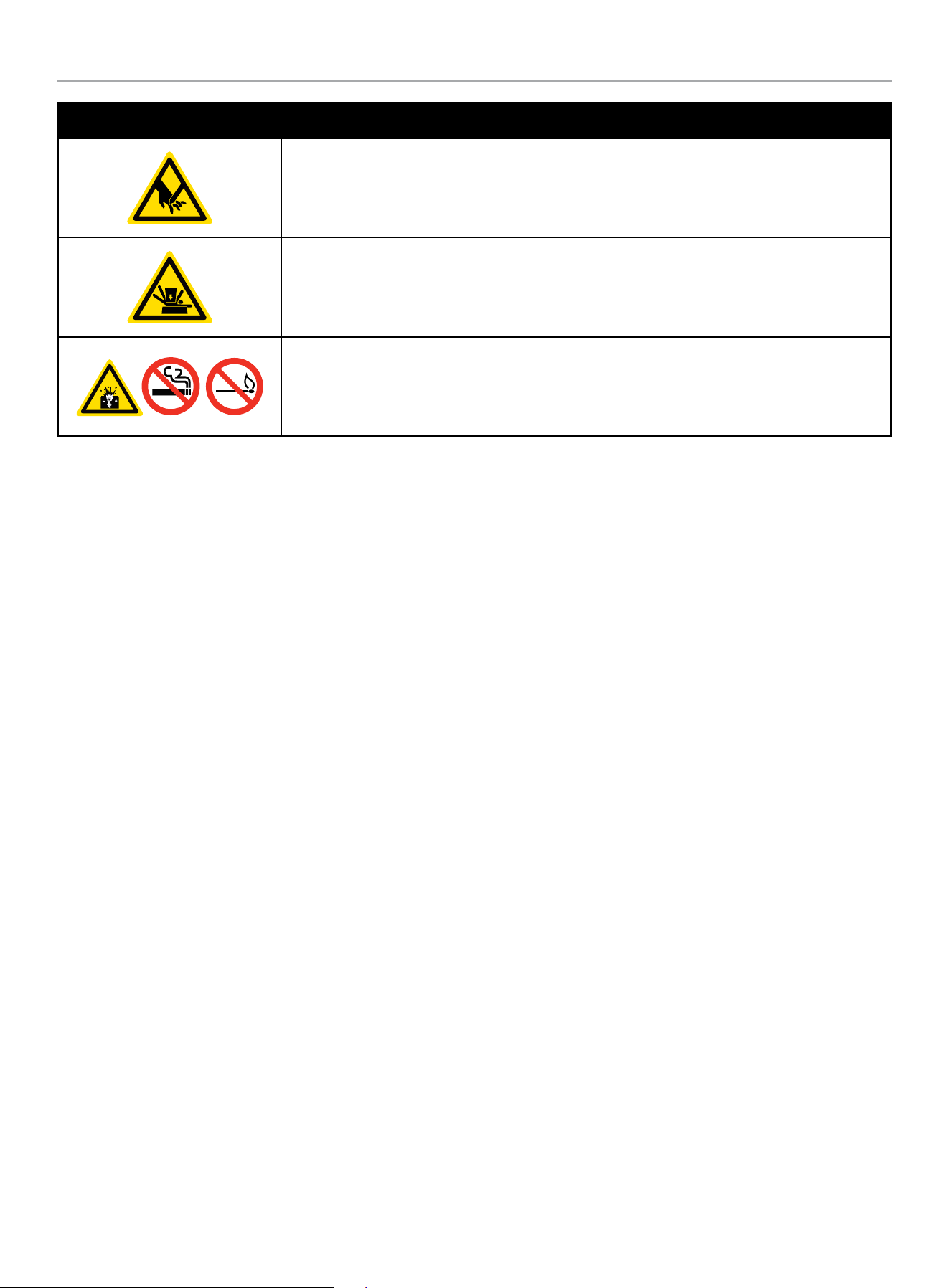
SYMBOL MEANING
Sever hazard (rotating blade)
Crush hazard (top)
Explosion Hazard. Battery gases are explosive. Keep sparks and flames away from the battery
compartment.
HOME STANDBY GENERATOR- ALL fleX CONTROLLER™ MODELS
SAFETY LABELS AND HANG TAGS
12
SAFETY LABELS AND HANG TAGS
WARNING
DO NOT operate the generator if there are missing or badly worn safety labels. Safety labels must be legible to alert personnel of safety
hazards.
Replace any illegible or missing label immediately. Missing safety labels must be replaced in their original position before the generator
is operated.
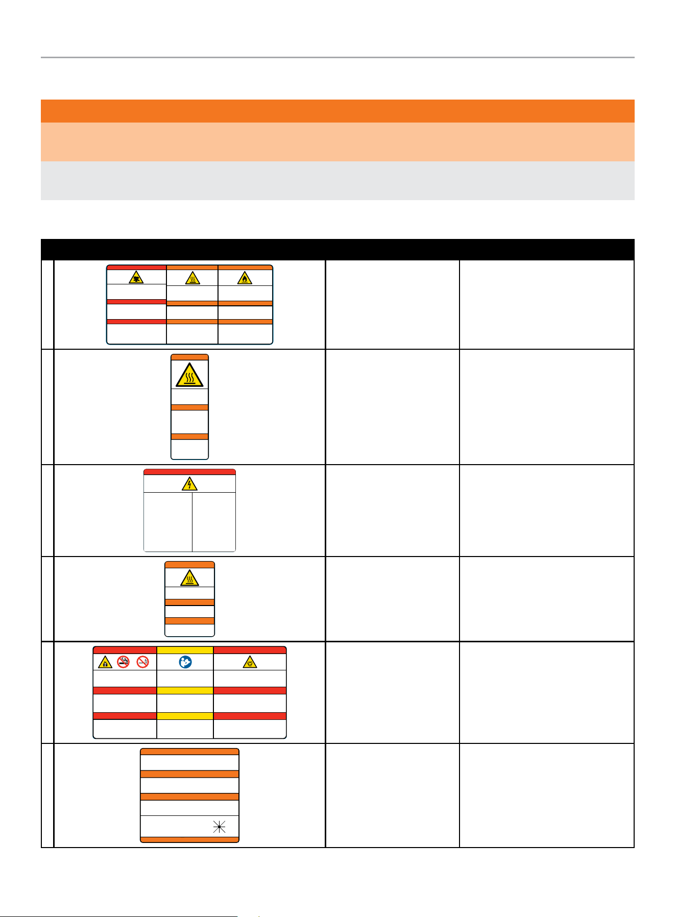
Labels
LABEL DESCRIPTION PART NO.
A
Poisonous Gas Hazard - Generator exh aust contain s carbon
monoxide, a colorless, odorless, poisonous gas. Breathing
carbon m onoxide will cau se nausea, dizz iness, fainti ng or
death. I f you start to fe el dizzy or weak, g et to fresh air
immediately.
Risque d’empoisonnement par le gaz - Les gaz
d'échappement de la génératrice contiennent du monoxyde de
carbon e, un gaz toxique i ncolore et inod ore. L'inhal ation de
monoxy de de carbone pro voque des nausée s, des
étourdissements, des évanouissements ou la mort. Si vous
commenc ez à vous sentir ét ourdi ou faible, r endez-vous
immédiatement à l'air frais.
Riesgo d e gas venen oso - Los gases de es cape del
generador contienen monóxido de carbono, un gas incoloro,
inodoro y venenoso. Respirar monóxido de carbono provoca
náusea s, mareos, desm ayos o la muerte. S i empieza a
sentir se mareado o débi l, busque aire fr esco inmediat amente.
DANGER
PELIGRO
2510-L-SF-E
Fire Haz ard - ALWAYS keep the sur rounding area
near gene rator clean and f ree of debr is and/or dry
vegeta tion. Th e generator may create sparks while
operating.
Risque d’incendie - Nettoyez TO UJOURS la sur face
à proximi té du grou pe électr ogène et enlevez le s
débris e t/ou la veg étation sèche. L e groupe
électrogène peut générer des étincelles pendant
son fonctionnement.
Riesgo d e incendi o - SIEMPRE mant enga el área
circund ante cerca del gen erador limpia y libre de
escombros y/o veget ación seca. El ge nerador p uede
crear chispas mientras está en funcionamiento.
WARNING
ADVERTENCIA
Burn Haz ard - DO NOT t ouch hot surfac es.
Avoid con tact with exhaust compon ents
and gases.
Risque de brûlure - NE touchez PAS le s
surfa ces chaudes. Evitez le cont at avec les
composants et les gaz d’échappement.
Riesgo de quemaduras - NO toque las
super ficies cal ientes. Evite el c ontacto con
los compo nentes de escape y g ases.
WARNING
ADVERTENCIA
DANGER
AVERTISSEMENT
AVERTISSEMENT
Poison, Burn and Fire
Warning
2510 -L-S F
B
2483-L-SF-C
Burn Hazard - DO NOT touch
hot surfaces. Allow the
engine and alternator to cool
to the touch before servicing.
Riesgo de quemaduras -
NO toque las superficies
calientes. Deje que el motor
y el alternador se enfríen
para tocarlos antes de
realizarles el mantenimiento.
WARNING
ADVERTENCIA
Danger de brulure - NE
TOUCHEZ PAZ les surfaces
chaudes. Laissez le moteur
et l’alternateur devenir froid
au toucher avant d’intervenir.
AVERTISSEMENT
Burn Warning 24 83- L-SF
C
Electrical Shock - ALWAYS close
and lock the generator covers
before operating. The generator
produces dangerous voltage.
Riesgo de descarga eléctrica -
SIEMPRE cierre y trabe las tapas del
generador antes de ponerlo en
funcionamiento. El generador
produce un voltaje peligroso.
Risque de choc électrique -
Fermez et verrouillez TOUJOURS les
capots de groupe électrogène avant
d’utiliser le groupe. Le groupe
électrogène génère des tensions
dangereuses.
PELIGRO DANGER DANGER
Electrical Shock Hazard - Do not
remove this access panel. The panel
should only be removed by an authorized
Service Dealer or a qualified electrician;
high voltage inside.
Riesgo de descarga eléctrica - No
remueva este tablero de acceso. El
tablero sólo deberá ser removido por un
distribuidor de servicio autorizado o un
electricista calificado; alto voltaje al
interior.
Risque de choc électrique - N’enlevez
pas ce panneau d’accès. Le panneau ne
devrait être enlevé que par un
concessionnaire d’entretien agréé ou un
électricien qualifié; haute tension à
l´’intérieur.
4647-L-SF-B
Electrocution Warning 4 647- L-S F
D
2473-L-SF-C
Burn Hazard - DO NOT touch hot surfaces.
Avoid contact with exhaust components
and gases.
Risque de brûlure - NE touchez PAS les
surfaces chaudes. Evitez le cont at avec les
composants et les gaz d’échappement.
Riesgo de quemaduras - NO toque las
superficies calientes. Evite el contacto con
los componentes de escape y gases.
WARNING
ADVERTENCIA
AVERTISSEMENT
Burn Warning 247 3-L-S F
E
Explosion Hazard - Batter y gases are
explosive. Keep sparks and flames away from
the battery compar tment.
Risque d’explosion - Les gaz dégagés par la
batterie peuvent exploser. Ecar tez les
étincelles et les flammes du compar timent
batterie.
Riesgo de explosión - Los gases de las
baterías son explosivos. Mantenga las
chispas y llamas alejadas del compartimento
de las baterías.
PELIGRO
Read Operator’s Manual - Read,
understand and follow all safety messages
in Intallation and Operator’s manuals.
Lisez le manuel d’utilisation - Lisez
comprenez bien et respectez tous les
messages de sécurité dans les manuels
d’installation et d’utilisation.
Lea el manual del operador - Lea,
comprenda y siga todos los mensajes de
seguridad en los manuales de instalación
y del operador.
CAUTION
PRECAUCIÓN
4413-L-SF-E
Starting Hazard - The generator may crank and start
without notice. Prevent the generator from accidental
star ting while the covers are open. See the safety
section of the operator’s manual for fur ther detail.
Riesgo de inicio - El generador puede encenderse y
ponerse en marcha sin previo aviso. Evite que el
generador se ponga en marcha accidentalmente
mientras las tapas están abiertas. Vea la sección de
seguridad en el manual del operador para más detalles.
PELIGRO
DANGER
MISE EN GARDE
DANGER
Risque au démarrage - Le groupe électrogène peut
tourner et démarrer sans préavis. Empêcher le
démarrage accidentel du génératrice lorsque le
couvercle est ouvert. Consultez la section sécurité du
manuel d’utilisation pour plus de détail.
DANGER DANGER
Explosion Warning, Read
OM, Starting Warning
4 413 -L-S F
F
4642-L-SF-B
ALTERNATE POWER SOURCE AVAILABLE -
STANDBY GENERATOR ON PREMISES.
AUTRE SOURCE DE COURANT DISPONIBLE -
GENERATEUR SUR SITE.
FUENTE DE CORRIENTE ALTERNA DISPONIBLE -
GENERADOR DE RESERVA EN EL SITIO.
GENERATOR LOCATION:
UBICACIÓN DEL GENERADOR:
EMPLACEMENT DU GENERATEUR:
NW
W E
N NE
SW S SE
ATTENTION
ATENCIÓN
ATTENTION
DO NOT REMOVE \ NO REMUEVA \ NE PAS ENLEVER
Alternate Power Source 4 642-L-S F

HOME STANDBY GENERATOR- ALL fleX CONTROLLER™ MODELS
SAFETY LABELS AND HANG TAGS
13
Hang Tags
HANG TAG DESCRIPTION PART NO.
1681-T-SF-B
ATTENTION
ALTERNATE POWER SOURCE AVAILABLE -
STANDBY GENERATOR ON PREMISES.
ATTENTION
AUTRE SOURCE DE COURANT DISPONIBLE -
GENERATEUR SUR SITE.
ATENCIÓN
FUENTE DE CORRIENTE ALTERNA DISPONIBLE -
GENERADOR DE RESERVA EN EL SITIO.
GENERATOR LOCATION:
UBICACIÓN DEL GENERADOR:
EMPLACEMENT DU GENERATEUR:
DO NOT REMOVE \ NO REMUEVA \ NE PAS ENLEVER
NW
W E
N NE
SW S SE
Alternate Power Source 1681-T-SF
HOME STANDBY GENERATOR- ALL fleX CONTROLLER™ MODELS
SAFETY LABELS AND HANG TAGS
14
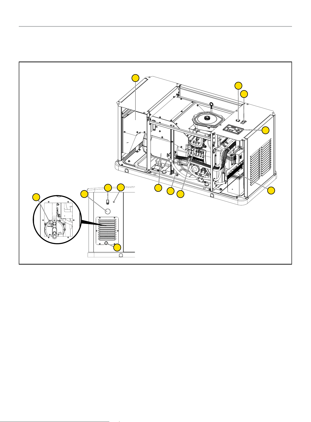
A. Serial number location
B. Dataplate
C. NFPA 37 Compliance
D. Oil hang tag
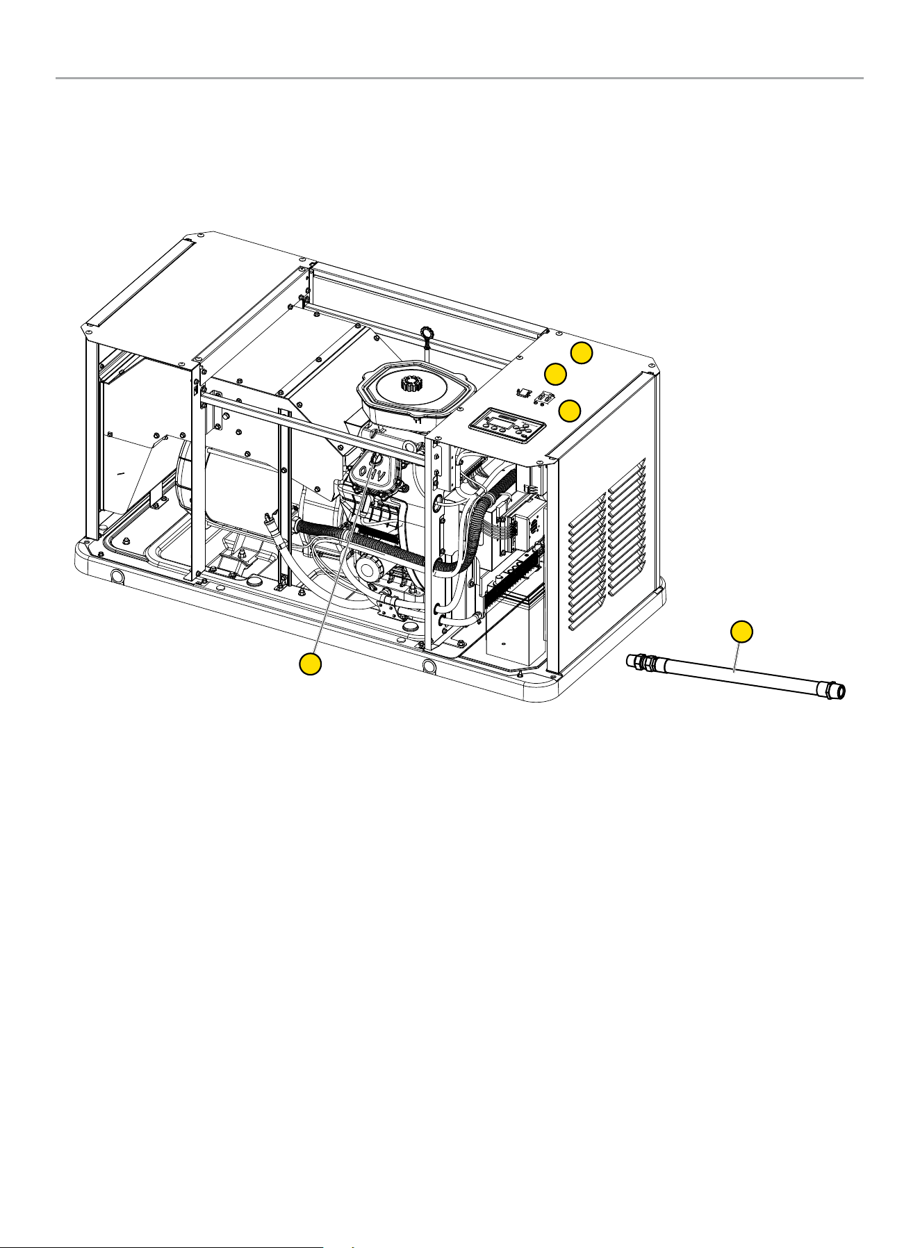
E. Alternate Power Source Hang tag and Label (not shown – in
the Operator’s Manual bag)
F. Flexible Fuel Line Hang tag
Safety label and Hang Tag locations
The safety labels have specific placement and must be replaced if they are unreadable, damaged or missing.
If a label comes off or becomes hard to read, contact Technical Support Team for possible replacement.
C
A
B
D
F
HOME STANDBY GENERATOR- ALL fleX CONTROLLER™ MODELS
GENERAL INFORMATION
15
GENERAL INFORMATION
Component Identification - Home Standby (HSB) Generator
12
1
2
3
5
2
4
11
7
6
8
10
9
1. Exhaust System
2. Generator ON/OFF
3. Main Circuit Breaker
4. fleX Controller
™
5. Batteries (not included, side cover)
6. Oil Drain Hose
7. Engine
8. Alternator
9. Electric Conduit Caps
10. Exterior Warning LED
11. Fuel Inlet
12. Fuel Pressure Reducing Valve/Fuel Shut Off
HOME STANDBY GENERATOR- ALL fleX CONTROLLER™ MODELS
GENERAL INFORMATION
16
Specifications
Home Standby Generator
Maximum continuous power, LPG 22 kW
Maximum continuous power, NG 19.8 kW
Rated voltage 120/240
Amps 183.4/91.7 LPG (propane), 165/82.5 NG (natural gas)
Harmonic distortion Less than 5%
Main line circuit breaker 100 amp
Phase Single
Frequency 60 Hz
Unit weight 557 lbs. (253 kg) (no battery)
Size (L x W x H) 56.3 x 28 x 28.5 in. (143 x 71 x 72.5 cm)
Engine
Type OHV Commercial V-Twin
No. of cylinders 2
Displacement 999 cc
Cylinder block Aluminum with cast iron sleeves
Ignition system TCI (Transistorised Coil Ignition)
Spark plug Champion RC12YC( NGK-BKR7ES-11)
Governor Electronic
Starter Electric 24V DC
Oil capacity- Dry 3.4 US qt (3.2 L)
Oil capacity- With oil filter change 2.5 US qt (2.4 L)
Oil Type 0W-40 Full Synthetic*
RPM 3600
Controls
Mode switch auto Auto start on utility failure
Mode switch manual Starts on demand
Mode switch off Stops unit/control and charger active
Ready to run/maintenance messages Standard
Programmable start delay Standard
Engine start sequence Standard
Starter lockout Standard
Battery charger/low battery indicator Standard
Charger fault Standard
AVR over voltage protection Standard
Low oil protection Standard
Safety fused Standard
Overcrank/overspeed/underspeed protection Standard
* After 25 hours, change oil per maintenance schedule. The recommended oil type for typical use is 0W-40 full synthetic oil. However, using the listed conventional oils
shown in the “Recommended Engine Oil Type” chart may be used for typical use. If running generator in extreme temperatures, refer to the “Recommended Engine Oil
Type” chart.

HOME STANDBY GENERATOR- ALL fleX CONTROLLER™ MODELS
GENERAL INFORMATION
17
Engine Torque Specifications
Crankcase Cover Bolts
..........................18.4 lbf-ft (25 Nm)
Connecting Rod Bolts ...........................18.4 lbf-ft (25 Nm)
Rocker Cover Screws .............................. 7 lbf-ft (10 Nm)
Cylinder Head Bolts ............................ 33.2 lbf-ft (45 Nm)
Intake Manifold Screws .........................16.2 lbf-ft (22 Nm)
Carburetor to Intake Manifold ..................... 7 lbf-ft (10 Nm)
Blower Housing ..................................... 7 lbf-ft (10 Nm)
Flywheel Nut ................................... 118 lbf-ft (160 Nm)
Ignition Coil Bolts ................................... 7 lbf-ft (10 Nm)
Starter Motor Bolts ..............................16.2 lbf-ft (22 Nm)
Spark Plug .......................................14.8 lbf-ft (20 Nm)
Air Cleaner box to Carb ............................ 7 lbf-ft (10 Nm)
Exhaust pipe nuts .............................. 25.8 lbf-ft (35 Nm)
Master Mixing Assembly Jets (Carburetor System)
Idle/low-speed Jet ...............................................NA
Main Jet ..........................................1.1 lbf-ft (1.5 Nm)
Fuel Inlet Chamber Screws ...................... 0.7 lbf-ft (1 Nm)
HOME STANDBY GENERATOR- ALL fleX CONTROLLER™ MODELS
GENERAL INFORMATION
18
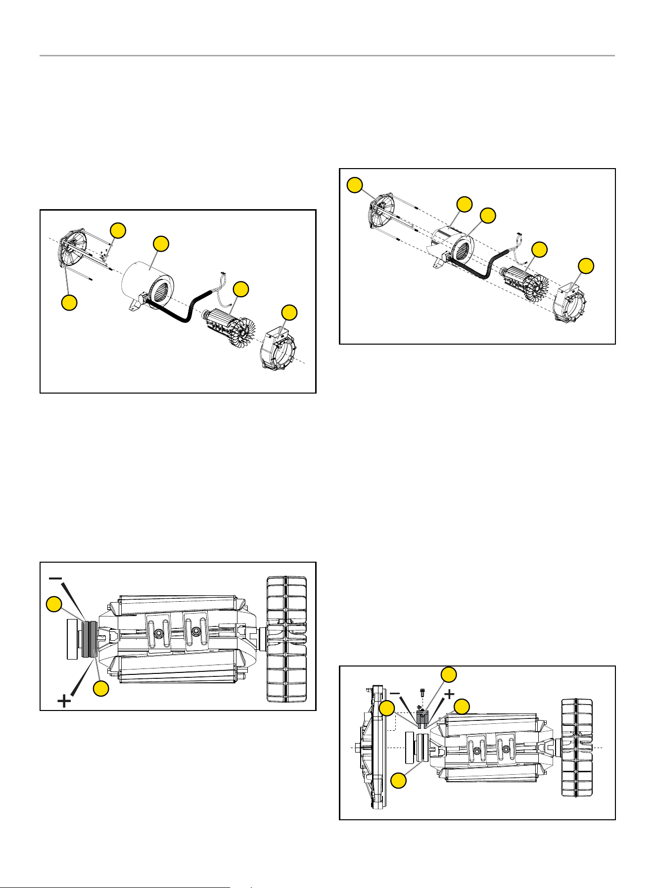
Alternator Overview
The alternator is made up with the following major components;
1. Rear bearing carrier
2. Brush holder assembly
3. Stator assembly (all copper wire)
4. 2 pole rotor (all copper wire)
5. Engine adapter
3
2
4
5
1
ROTOR ASSEMBLY
The alternator has a 2-pole rotor, which means the rotor has a
single south magnetic pole and a single north magnetic pole.
As the rotor spins, its magnetic field passes through the stator
assembly windings and voltage is induced into the stator windings.
This is known as induction. The rotor shaft has a negative (-) slip
ring (1) and a positive (+) slip ring (2), with the negative (-) nearest
the bearing carrier. The rotor shaft is held in place with single
through bolt.
1
2
STATOR ASSEMBLY
The stator houses AC power windings (1) and excitation windings
(2). It is held in place with 4 bolts that pass through the bearing
carrier (3) and engine adapter (5), then attached to the engine
mounting flange. In combination with the rotor assembly (4), they
generate the electrical output of the HSB.
3
1
2
5
4
BRUSH HOLDER AND BRUSHES
The brush holder is a component that holds the brushes in a
stationary position enabling them to maintain contact with the
rotating surface commutator rings on the rotor. The brush holder
(4) is attached to the rear bearing carrier by means of two M6 x
12 bolts. A negative (-) brush (1) and a positive (+) brush (2) are
retained in the brush holder (4). The negative (-) brush rides on the
slip ring nearest the bearing carrier. The brushes are spring loaded
to maintain contact.
A RED wire connects to the positive (+) brush and a BLACK wire to
the negative (-) brush. Rectified and regulated excitation current,
as well as current from the field boost circuit, are delivered to the
rotor windings via the RED wire, and the positive (+) brush and
slip ring. The excitation and field boost current passes through the
windings and to the frame ground via the negative (-) slip ring and
brush, and the BLACK wire.
The current flow creates a magnetic field around the rotor having
a flux concentration that is proportional to the amount of current
flow.
1
3
2
4

HOME STANDBY GENERATOR- ALL fleX CONTROLLER™ MODELS
UNPACKING
19
UNPACKING
WARNING
The HSB weighs more than 500 lbs. (227 kg).
Use the aid of additional assistants and exercise caution during
installation.
Inspect the generator for damaged or loose parts. DO NOT operate
the generator if any components are damaged or loose. Contact
your dealer for assistance.
1. Cut banding straps.
2. Remove top lid.
3. Remove center cardboard supporting rib.
4. Lift cardboard housing and set aside.
5. Remove plastic covering and set aside.
6. Remove 4 securing clamps. Save if going to use anchor bolts
to secure to concrete pad (not supplied).
7. Insert 2 lifting rods (not supplied) into lifting holes at each end
of the base.
8. Discard all shipping materials and recycle if possible.
NOTICE
If you know the length of run for wires you may want to install
the ATS voltage wires now before setting unit to industry
17.7 in. from fire rated wall and when code permits. Also,
install the wires, some of the gas delivery pipes and flex hose
now while you have ample room at tailgate height before the
generator is put in its permanent location. Use cardboard
when kneeling.
HOME STANDBY GENERATOR- ALL fleX CONTROLLER™ MODELS
INSTALLATION
20
INSTALLATION
Placement & Installation Guidelines for Champion Home Standby Generators to Reduce the
Risk of Fire
NATIONAL FIRE PROTECTION ASSOCIATION (NFPA)
STANDARD NFPA 37 REQUIREMENTS AND TESTING
Requirements:
NFPA 37 2010, section 4.1.4, Engines Located Outdoors.
Engines, and their weatherproof housings if provided, that are
installed outdoors shall be located at least 1.5 m (5 ft.) from
openings in walls and at least 1.5 m (5 ft.) from structures having
combustible walls. A minimum separation shall not be required
where either of the following conditions exist:
1. The adjacent wall of the structure has a fire resistance rating
of at least 1 hour.
2. The weatherproof enclosure is constructed of noncombustible
materials and has been demonstrated that a fire within the
enclosure will not ignite combustible materials outside the
enclosure.
Annex A Explanatory Material
A.4.1.2 (2) Means of demonstrating compliance are by means of
full-scale fire tests or by calculating procedures, such as those
given in NFPA 555, Guide on Methods for Evaluating Potential for
Room Flashover.
To comply with condition 2 the weatherproof enclosure has
been constructed of non-combustible materials and full-scale
fire tests have been performed to demonstrate that a fire within
the enclosure will not ignite combustible materials outside the
enclosure.
Based on this testing and the requirements of NFPA 37, Sec.
4.1.4, the guidelines for installation of the Champion home
standby generator are changed to 17.7 inches (45 cm) from the
backside of the generator to a combustible wall. All other location
and distances remain the same as noted in the Operators and
Installation manuals.
These guidelines are based upon fire testing of the generator
enclosure and Champion’s requirement for air flow for proper
operation. Local codes may be different and more restrictive.
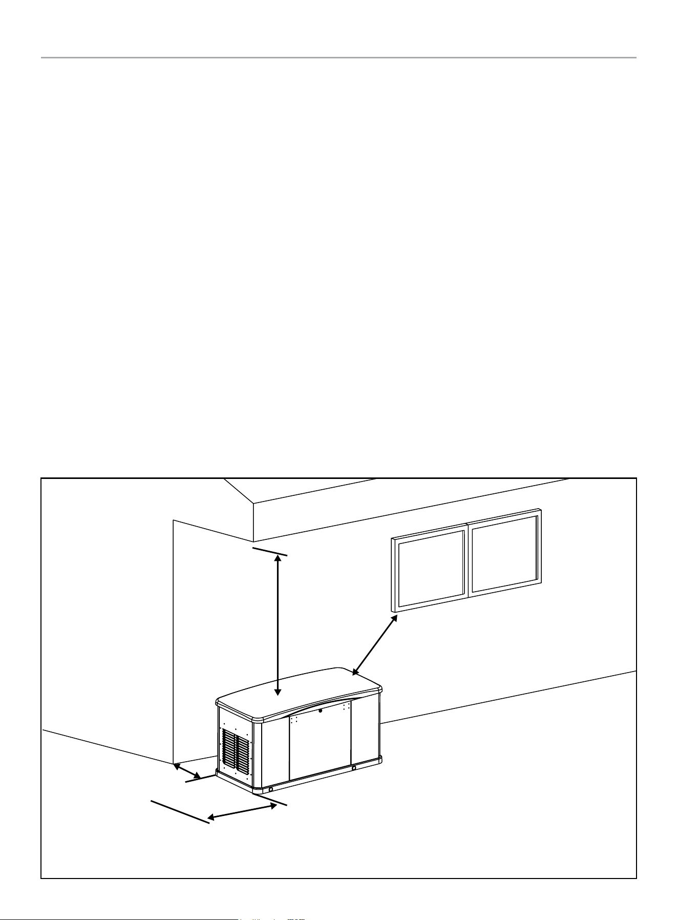
Minimum 17.7 in.
from any buildings
Minimum 5 ft. clearance
beyond exhaust end
Minimum 5 ft.
from any windows
Minimum 5 ft.
vertical clearance

HOME STANDBY GENERATOR- ALL fleX CONTROLLER™ MODELS
INSTALLATION
21
Intertek Group PLC Label
Located inside the generator, near the serial number or nameplate label.
NFPA® 37 Standard for the Installation and Use of Stationary Combustion Engines and Gas Turbine
The National Fire Protection Association (NFPA) standard NFPA 37 establishes criteria for minimizing the hazard of fire during the
installation and operation of stationary combustion engines. NFPA 37 limits the spacing of an enclosed generator from openings in walls,
structures and combustible materials outside the enclosure.
NFPA 37 (2015): Section 4.1.4 stipulates that engines installed outdoors shall be located at least 5 ft. (1.5 m) from structures having
combustible walls. Further, a minimum separation shall not be required where the following conditions exist:
– All walls of the structure that are closer than 5 ft. from the engine enclosure have a fire resistance rating of at least 1 hr., or
– The weatherproof engine enclosure is constructed of noncombustible materials, and it has been demonstrated that a fire within the
enclosure will not ignite combustible materials outside the enclosure.
Intertek Group PLC performed a full-scale fire test under a worst-case fire scenario within the stationary generator enclosure to determine
the ignitability of combustible material near the stationary generator. The enclosure is made of non-combustible materials and the results
and conclusions of the test indicate that a fire within the enclosure would not pose any risk of ignition to nearby combustible materials
or structures. Intertek Group PLC is certifying that this model complies with clause (2) of Section 4.1.4 of NFPA 37 when installed at a
minimum distance of 450 mm (17.7 in.) from a combustible wall.
Champion HSB units have been run and tested at the factory prior to shipment. They do not require any type of break-in period.
ID: 230700789HZH-001
Conforms to / Conforme à:
NFPA 37 4.1.4 CL. 2

HOME STANDBY GENERATOR- ALL fleX CONTROLLER™ MODELS
INSTALLATION
22
Site Selection, Preparation and Placement
These items are important to the overall performance of the HSB
generator. Many items covered in this section are not optional and
are requirements under Federal, State and Local codes. As with
all generators, your generator must be installed in accordance
with current NFPA-37, NFPA 54, NFPA 58 and NFPA-70 standards.
Contact your local electrical inspector or city hall to insure you
are aware of all codes and regulations. Install the equipment in
compliance with the National Electric Code (NEC). For Canada
installations, refer to Canadian Electrical Code (CEC). Contact your
natural gas supplier to verify that increased BTU gas demand can
be handled with the existing NG meter. The same should done for
LPG fueled generators. This generator in the enclosure is designed
to be installed outdoors only.
Champion HSB units are run and tested at the factory prior to
being shipped. They do not require any type of break-in period.
SUGGESTED SITE SELECTION
The installation of the HSB must comply strictly with NFPA 37,
NFPA 54, NFPA 58 and NFPA 70 standards.
Always install your generator within 20 feet of the NG meter, the
closer the better. This will reduce expensive costs of running fuel
line. In some cases longer runs of fuel line, when not properly
sized may cause inadequate fuel delivery. This could result in
poor starting, lower outputs and diminished overall performance
of the unit. The Champion HSB is shipped from the factory set
up for natural gas (NG) fuel. The HSB can be converted to LPG
if required. Orifices in the master mixer assembly (carburetor)
MUST be changed. The LPG orifices are shipped with the unit and
include installation instructions.
Install the unit in a location where the sump pump discharge,
rain gutter downspouts, roof run off, landscape irrigation, natural
ponding or water sprinklers will not flood the unit or spray the
enclosure entering any inlet or outlet opens.
Position the unit in an area where prevailing winds will carry
the exhaust gas away from any potentially occupied building or
structure.
Install the unit where leaves, grass, snow, ect., will not obstruct
air inlet and outlet openings. If prevailing winds cause blowing or
drifting, you may consider building a windbreak, planting trees or
shrubs within the guidelines and codes applicable.
Watch out for roof overhangs. Snow, ice or rain shouldn’t be
permitted to accumulate on the roof and then cascade onto the
unit.
DANGER
Engine exhaust from the unit is hot, poisonous and dangerous.
Exhaust must be allowed to dissipate into a free air zone as
listed in the applicable codes with no obstructions.
Direct the HSB exhaust away from or parallel to the building or
structure. DO NOT direct the HSB exhaust toward a potentially
occupied building, structure, windows, doors, ventilation intakes,
soffit vents, crawl spaces, open garage doors or other openings
where exhaust gas could accumulate and enter inside or be drawn
into potentially occupied buildings or structures.
Install the unit on higher ground where water levels will not rise
and endanger it. This unit shouldn’t be operated in standing water.
DO NOT place HSB waterproof enclosure under a deck or other
type of structure that may confine or restrict airflow. Operate
HSB only outdoors, where adequate ventilation and air movement
is available. Avoid installations under decks, inside garages or
carports, in basements, along home exterior within 5 feet (1.5m)
of home vent, roof overhang vents, a window that can be opened,
or other such home invasion points. Use the same precautions
when installing HSB at property line, close to a neighbor’s home,
or any building or structure that houses animals.
DANGER
Running engines give off carbon monoxide (CO), an odorless,
colorless, invisible, poisonous gas.
Breathing carbon monoxide (CO) will cause fatigue, headache,
dizziness, vomiting and in prolonged conditions, even
death. Carbon monoxide (CO) detectors MUST be installed
and maintained indoors according to the manufacturer’s
instructions/recommendations. Smoke alarms cannot detect
carbon monoxide (CO) gas.
The back of the HSB locates the fuel and wire entry points. When
placement/mounting is done this side generally faces the closest
point to each of those sources.
It is always recommended to prepare a drawing showing location
of HSB, typical gas utility approach, circuit connections and full
load connections.
Similar considerations should be given to the location of the ATS
(automatic transfer switch) in relationship to the HSB generator.
The closer to both the fuel meter and the main utility panel
the better. The key point here is, the closer to fuel meter is the
suggested direction to go, wire is cheaper to run and more flexible.
SUGGESTED PREPARATION
A concrete pad can be poured or purchased through Champion
and the HSB secured to it. In some areas a concrete pad is
required due to high wind potential. Check local codes to see what
type of mounting base is required. If a concrete pad is required,
all federal, state and local codes should be followed. Unless
mandated by federal, state or local code, a concrete pad is not
required.
HOME STANDBY GENERATOR- ALL fleX CONTROLLER™ MODELS
INSTALLATION
23
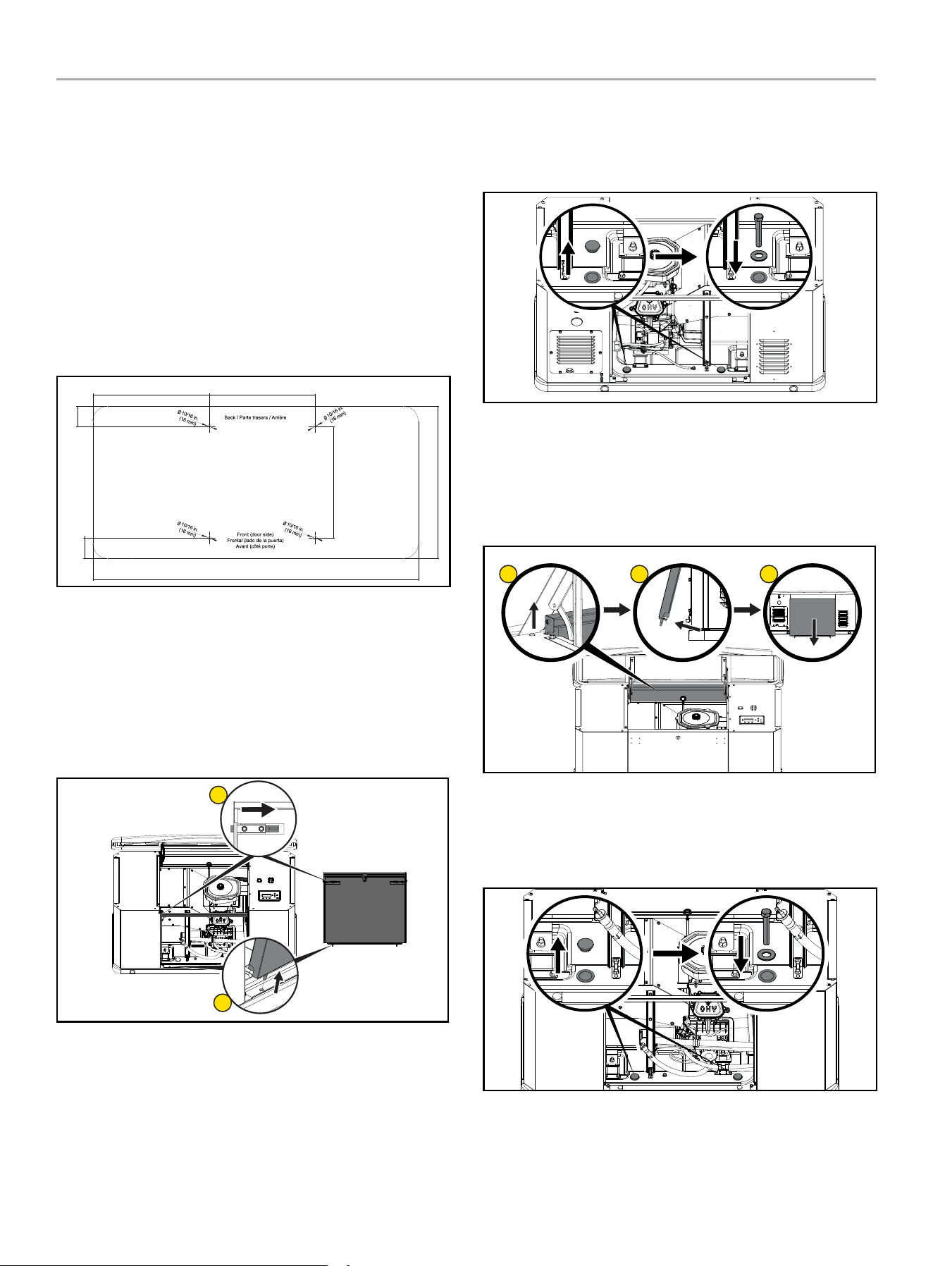
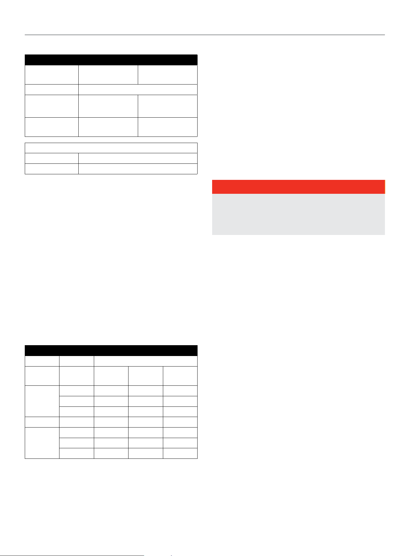
22-KW (MODEL 201202)
1. Below template may be found on the inside top cover of your
home standby packaging or as a loose folded paper insert
to help assist you in 1:1 drilling your own holes into your
concrete pad if you are not choosing the approved pad.
2. This template shows the outline of the plastic base on
your home standby.
3. The bolts and washers which tie your home standby to the
concrete pad are included for the approved pad only. If you
choose your own hardware, they must meet hurricane ratings
and fit into the home standby properly. Pay attention to
proper torque values noted.
18.9 in( )480 mm
19.8 in( )502 mm
17.9 in( )455 mm
3.5 in(88 mm)
55.2 in( )1402 mm
25.8 in( )656 mm
3.5 in(88 mm)
Front
See Enclosure and Access section in the Operator’s Manual for
more details on access and panel removal.
1. Open the top cover and remove the front panel. This front
panel is held position with 2 spring loaded pins on the inside.
Press inward on each side. Tilt back from the top and lift from
the base.
1
2
2. Remove bushing cap, and install washer and bolt as shown.
Bolt and washer will tighten inside the hurricane bushing
below the home standby pan. Torque to 3.2 Nm (2.4 lbf-ft) or
hand tight and ⅛ turn more.
Back
3. With top cover open, from the front, lift up on the back panel,
then kick out the bottom edge towards the back once the
panel pins clear. From the back, pull the panel down and out
from under the top cover.
1
2 3
4. Remove bushing cap, and install washer and bolt as shown.
Bolt and washer will tighten inside the hurricane bushing
below the home standby pan. Torque to 3.2 Nm (2.4 lbf-ft) or
hand tight and ⅛ turn more.
If no concrete pad is being used, Champion recommends using a
mixture of pea gravel and sand or crushed stone for placement of
the mounting pad. The mounting pad MUST be level. The gravel
mixture or crushed stone is to permit water runoff, drainage and
reduce ponding of water around the HSB.
HOME STANDBY GENERATOR- ALL fleX CONTROLLER™ MODELS
INSTALLATION
24
Dig an area 5 inches (12.7 cm) deep that is 6 inches (15.2 cm)
longer and wider than the foot print of the HSB. See Specifications
section for L x W dimensions.
Cover the dugout area with a weed barrier or landscape cloth if
desired.
Fill the area with pea gravel and sand mixture or crushed stone.
Final stone level must be 2 or 3 inches (5.1 or 7.6 cm) higher than
the original ground level to ensure water run-off and drainage.
Compact the fill, this is to provide a firm base for the HSB.
Remember the final stone level must be 2 or 3 inches (5.1 or
7.6 cm) higher than the original ground level to ensure water run-
off and drainage.
Tools required
1. General SAE and Metric hand tools, wrenches, sockets and
screwdrivers.
2. Standard electrician’s hand tools, drill and bits.
3. Monometer (for checking fuel pressures).
4. Meter capable of measuring AC/DC Voltage and Frequency
5. Safety apparel
Inspect the unit. Carefully inspect the HSB for any damage
that may have occurred during shipment and delivery. If loss
or damage is noted at the time of delivery, have the person(s)
making delivery note all damage on the freight bill and affix their
signature under the consignor’s memo of loss or damage. If loss
or damage is noted after delivery, separate the damaged materials
and contact the carrier for claims procedures. Parts damaged in
shipping are not covered under Champion warranty.
Unbox the unit, by removing the exterior shipping carton. If ATS
is included, remove the packaging and lift it out. Remove the 4
shipping brackets, 2 on each end that hold the HSB to the wood
shipping pallet. This pallet is for shipping/transportation only and
cannot be used as a mounting pad in any form. Exercise caution
when removing the HSB from the wood pallet, dragging it off the
wood pallet will damage the HSB base. The HSB must be lifted
from the wood pallet to separate.
Contact your natural gas (NG) supplier about the meter size. Most
meters must be replaced with a larger BTU size, due to a larger
demand of BTU’s from the HSB and appliances during operation
(utility outage). This also applies to HSB utilizing LPG.
SUGGESTED PLACEMENT
WARNING
HSBs weigh approximately 300-600 lbs (136-272 kg)
depending on the model. Proper tools, equipment and qualified
personnel should be used in all phases of handling and moving
the HSB. Do not lift or move the HSB without assistance. Do
not lift the unit by the roof structure or any other enclosure
component as damage to the HSB may occur, including
possible injury of persons when handling and or moving the
HSB in this manner.
The Site Selection has been completed, all federal, state and local
codes have been reviewed and applied as mandated by the NFPA
standards and all other related codes/standards.
Preparation has been completed and everything has been properly
prepared to place the HSB.
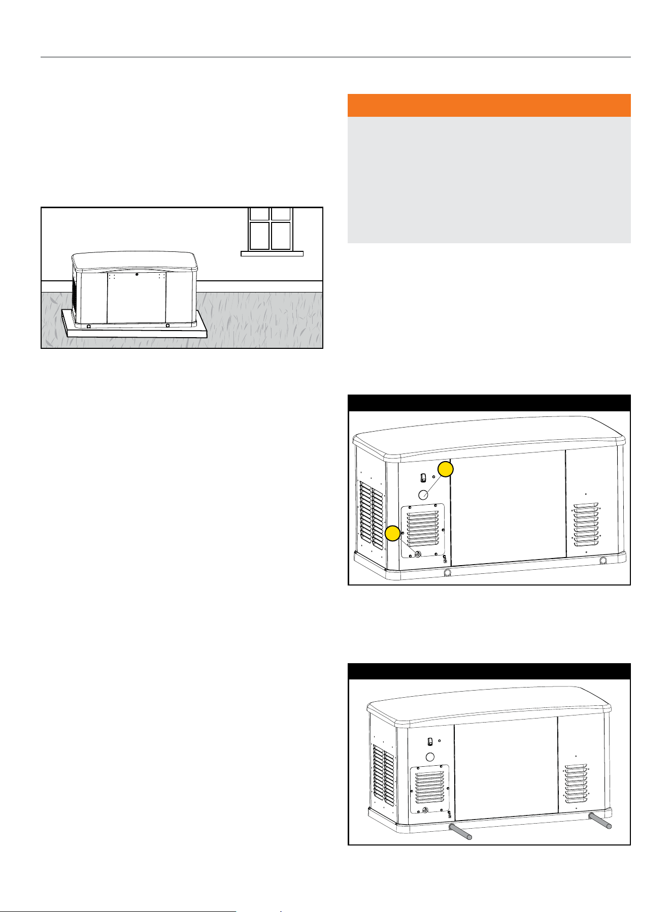
The rear right side of the HSB locates the fuel (A) and electrical (B)
entry points. When placement is done this side generally faces the
closest point to each of those sources for fuel and electrical entry.
22-kW (Model 201202)
A
B
Two (2) 5 feet (1.5 m) lengths of 1 inch (2.5 cm) steel pipe
(supplied by the installer), are required to lift the HSB. Insert the
steel pipes through the lifting holes located near the HSB base in
the composite pad, on each end.
22-kW (Model 201202)

HOME STANDBY GENERATOR- ALL fleX CONTROLLER™ MODELS
INSTALLATION
25
You may also lift the HSB using a properly rated strap, lift, hook
and hoist procedure attached to both steel lifting pipes, provided
that you use spreader bars to ensure that the belts, chains or
cables DO NOT touch/contact the HSB.
Once the HSB has been placed, check to make sure it is level. If it
isn’t, make adjustments prior to installation procedures start.
Installation Preparation
WARNING
Improper installation can result in personal injury and damage
to the generator. It may also result in the warranty being
suspended or voided. All the instructions must be followed
including location clearances and pipe size.
Once Site Selection, Preparation and Placement has been
completed, you can proceed to Installation Preparation. Without
these in place you may encounter problems moving forward.
There are a number of key items that MUST be addressed prior
to the physical installation of the HSB. The installation of the HSB
must comply strictly with all applicable codes, standards and
regulations (NFPA 37, NFPA 54, NFPA 58, and NFPA 70).
Check and confirm that the fleX Controller
™
is in the “OFF”
position. It is recommended to pull the control module fuse located
on the front panel and turn the circuit breaker to the OFF position.
Champion HSB units have been run and tested at the factory prior
to being shipped. They do not require any type of break-in period.
CAUTION
Check oil level, add oil if required. Add oil to full capacity as
stated in the specification section before starting the HSB.
Never operate the HSB with the engine oil level below the
“ADD” mark on the dipstick, doing so could damage the
engine. Check the oil level and add the appropriate viscosity
and amount indicated on the oil dipstick full line. The
recommended oil type for typical use is 0W-40 full synthetic
oil.
The following will be covered;
1. Fuel Requirements and Recommendations
2. Fuel Consumption
3. NG Pipe Sizing, flexible fuel line
4. LPG Vapor Pipe Sizing, flexible fuel line
5. Converting to LPG
6. Full Flow Shut Off Valve
7. Sediment Trap
8. Checking Pressure with a Manometer
9. Battery Requirements, Installation & Service
10. Wiring of the HSB
1. FUEL REQUIREMENTS AND RECOMMENDATIONS
The following NG and LPG fuel information is provided to assist
the fuel installer. This information should not be deemed to be
all inclusive or to conflict with local dry fuel codes. Consult your
local fuel supplier or Fire Marshall for guidance on proper local
codes and installations. Local codes will mandate correct routing
of gaseous fuel line piping around gardens, shrubs and other
landscaping to prevent any damage.
Special considerations should be given when installing the
HSB where local conditions include might flooding, tornadoes,
hurricanes, earthquakes and unstable ground. These are
considerations for the flexibility and strength of piping and their
connections.
NG is lighter than air and will collect in high areas. LPG is heavier
than air and will settle in low areas.
DANGER
Gaseous fuels such as NG and LPG are highly explosive.
Even the slightest spark can ignite such fuels and cause an
explosion, which could cause burns, fire or explosion resulting
in serious injury, property damage or even death. NO leakage
is permitted.
Recommended fuels should have a BTU content of at least 1,000
BTU’s per cubic foot for NG, or at least 2,500 BTU per cubic foot
for LPG. Ask the fuel supplier for the BTU content of the fuel.
Before NG fuel lines plans are made, call your NG supplier, provide
them information on the amount cubic feet/hour and the BTU’s/
hour that the HSB will use, and ask if the NG meter and primary
regulator can accommodate the addition of the NG generator. NG
companies have different meters for increased BTU demands.
Utilize the “Fuel Consumption (BTU) Chart” contained in this
manual or the Installation Manual for your specific HSB model.
Verify that the current gas meter is capable of providing enough
fuel flow to include household appliances and other loads
including the addition of the HSB. Check the NG primary regulator,
connected at the NG meter output. The correct primary regulator
is set at 5 to 7 inches water column. The existing primary
regulator may be undersized once the HSB is added.
The HSB engine can run on either NG or LPG. The HSB comes
equipped from the factory to run on NG. If your installation
requires the engine to run on LPG, orifices in the master mixer
assembly (carburetor) MUST be changed. The LPG orifices are
shipped with HSB. Refer to “Converting to LPG” in this manual or
the “Operator’s Manual” for your specific HSB model.
HOME STANDBY GENERATOR- ALL fleX CONTROLLER™ MODELS
INSTALLATION
26
Fuel System Requirements
22-kW (Model 201202)
Fuel System
Requirements
LPG NG
Fuel Supply Inlet 3/4 in. NPT
Fuel Supply
Pressure
10 – 12 inch-H20.
(2.5 – 3.0 kPa W.C.)
5 – 7 inch-H2O
(1.2 – 1.7 kPa W.C.)
Maximum flow
rate
14.23 l/hr
@22 kW
8.29 m
3
/hr
@19.8 kW
Nominal Fuel Rating
LPG 2500 BTU/ft
3
NG 1000 BTU/ft
3
Install the fuel system in accordance with NEC and local codes.
The HSB is EPA Phase 3 certified for LPG and NG fuels.
2. FUEL CONSUMPTION
Air density is less at high altitudes, resulting in less available
engine power. Engine power will decrease 3.5% for each 1,000
feet (300 m) above sea level and 1% for each 10° F (5.5° C) above
77° F (25° C). Make sure these factors are considered when
determining total HSB load.
The gas supply and pipe MUST be sized at 100% load BTU rating.
Understand that as a specific fuel supply line pipe diameter is
extended in length, its ability to carry the volume of gas diminishes
in direct proportion. Improper fuel pipe sizing is the number one
reason for poor operating performance (hard starting, output).
Required fuel pressure for NG is 5 – 7 inches water column.
Required fuel pressure for LPG vapor is 10 – 12 inches water
column. These are estimated fuel supply requirements listed.
22-kW (Model 201202)
Consumption
Fuel
Type
Percent
Load
L/hr gal/hr BTU/hr
LPG
0% 3.87 1.02 93,472
50% 8.86 2.34 214,151
100% 14.23 3.76 344,020
m
3
/hr ft
3
/hr BTU/hr
NG
0% 2.59 91.4 91,359
50% 5.88 207.7 207,721
100% 8.29 292.6 292,617
3. NG PIPE SIZING
The HSB leaves the factory set up for NG, no changes or alteration
need to be made if NG is the fuel source you are going to use
The following NG fuel information is provided to assist the fuel
installer. This information should not be deemed to be all inclusive
or to conflict with local dry fuel codes. Consult your local fuel
supplier or Fire Marshall for guidance on proper local codes and
installations. All piping must comply with NFPA 54 and related
codes. Gas line connections should be made by a certified
plumber familiar with local codes.
Always use AGA approved gas pipe and a quality pipe sealant or
joint compound. The piping should conform to federal and local
codes, rigidly mounted and protected from vibration. Piping should
be black iron or steel to avoid reacting with the sulfur in the fuel.
DANGER
NG is highly explosive. Even the slightest spark can ignite and
cause an explosion, which could cause burns, fire or explosion
resulting in serious injury, property damage or even death. NO
leakage is permitted. Safety is important.
Gas pipe sizing is critical to the proper operation of the HSB. The
HSB fuel inlet size has no bearing on the proper gas pipe size
running to the HSB. Gas supply and pipe MUST be sized at 100%
load BTU rating. Understand that as a specific fuel supply line pipe
diameter is extended in length, its ability to carry the volume of
gas is diminished in direct proportion.
Pipe sizes are measured by inside diameter (ID) to include any
fittings, valves, elbows, tees or angles. Add 2.5 feet (.76 m) per
bend, tee or angle in the pipe line to the overall distance, for each
90 degree elbow, add 8 feet (2.4 m) to the measurement. Use a
pipe sealant or joint compound approved for use with LPG/NG on
all threaded fittings to assure zero leakage.
A dedicated NG fuel supply line pipe and primary gas regulator is
mandatory for proper operation. A minimum of one (1) approved,
external manual full flow shutoff gas valve must be installed in the
fuel supply line pipe leading to the HSB. This line must be easily
accessible.
HOME STANDBY GENERATOR- ALL fleX CONTROLLER™ MODELS
INSTALLATION
27
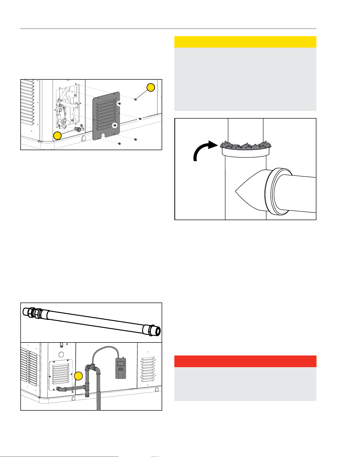
FUEL LINE
Remove access panel by removing six [6] M6 inside hex bolts (1)
with 5 mm (included) or 3/16” allen wrench. Pull off or unscrew
protection cap (2) from fuel line before continuing with further
connections.
2
1
FLEXIBLE FUEL LINE
A flexible fuel line (1) is to be installed between the stationary fuel
supply line pipe and the fuel inlet pipe to the HSB. This flexible
fuel line is included with the HSB. The purpose of the flexible fuel
line is to ensure that vibration from the HSB does not cause a gas
leak at one of the connection points. The flexible fuel line is not
to be installed underground, in contact with any enclosure parts
or contact with the ground. The entire flexible fuel line must be
visible for periodic inspection and must not be concealed within
nor contact nor run through any wall, floor, partition or fence.
Never bend flexible fuel line to avoid using an elbow. Bending
the flexible fuel line decreases its ability to absorb vibrations
and could restrict the actual fuel flow. Because a HSB engine is
prone to vibration, a flexible piping connection to the gas supply
is required. Connect the HSB to the gas supply piping with an
approved flexible gas line according to local codes. The flexible
gas line also protects against settlement between the HSB pad
and the ridged gas supply piping.
1
CAUTION
Check for leaks by spraying all connection points with a soap
solution made of dishwashing liquid and water. If you see
bubbles, this indicates a leak and the connection should be
corrected. Check each connection point, there should not be
a visible bubbling when soap solution applied. Installed piping
must be properly purged and leak tested, in accordance with
applicable codes and standards. A sediment trap should be
placed in the fuel supply pipe line to drain any condensation.
Bubble
indicates leak
Bubbles
indicate leak
Refer to the “Fuel Pipe Sizing Chart” contained in this manual.
Champion HSB units have been run and tested at the factory prior
to shipment. They do not require any type of break-in period.
4. LPG VAPOR PIPE SIZING
The HSB leaves the factory set up for NG. If your installation
requires the engine to run on LPG, simply rotate the Fuel Select
Dial on top of the mixture assembly. The jet block is enclosed
(shipped) with the HSB.
The following LPG information is provided to assist the fuel
installer. This information should not be deemed to be all inclusive
or to conflict with local dry fuel codes. Consult your local fuel
supplier or Fire Marshall for final answers on proper local codes
and installation. All piping must comply with NFPA 54 and related
codes. Gas line connections should be made by a certified
plumber familiar with local codes.
DANGER
LPG is highly explosive. Even the slightest spark can ignite and
cause an explosion, which could cause burns or fire resulting
in serious injury, property damage or even death. No leakage
is permitted. Safety is important.
Gas pipe sizing is critical to the proper operation of the HSB. The
HSB fuel inlet size has no bearing on the proper gas pipe size
running to the HSB. Gas supply and pipe MUST be sized at 100%
load Btu rating.
HOME STANDBY GENERATOR- ALL fleX CONTROLLER™ MODELS
INSTALLATION
28
Pipe sizes are measured by inside diameter (ID) to include any
fittings, valves, elbows, tees or angles. Add 2.5 ft. (.76 m) per any
bend, tee or angle in the pipe to the overall distance. For each 90
degree elbow, add 8 ft. (2.4m) to the measurement. Use a pipe
sealant or joint compound for use with LPG/NG on all threaded
fitting to assure zero leakage.
The LPG must be a vapor withdrawal system. The HSB will not
work on a liquid withdrawal system. Gas line connections should
be made by a certified plumber familiar with local codes.
New LPG tanks and existing LPG tanks already located at the
installation site, have a primary fuel regulator set and intended for
home heating and cooking. This regulator might not be properly
sized to accommodate the addition of the HSB. Contact the local
LPG supplier to properly size the fuel regulator.
Make sure the tank is sized large enough to provide the required
Btu’s for the HSB and all connected appliances.
The LPG fuel tank must have a dedicated primary fuel regulator
mounted at the tank fuel outlet point and set for 6 ounce pressure,
10 -12 inch water column. A direct, dedicated fuel line connected
directly to the HSB mounted secondary regulator, also set at
6 ounce pressure, 10 -12 inch water column. When sizing the
secondary regulator for LP applications be sure to note the
maximum individual load capabilities. This could impact HSB
starting performance if sized to small. It is not recommended to
reduce the fuel supply line pipe exiting the secondary regulator
unless to accommodate the flexible fuel line required to install and
shipped with the unit. The may result in starting or performance
issues with the HSB.
Make sure fuel supply line pipe includes an on/off external manual
full flow shut off gas valve at both the LPG tank and at the point of
connection to the HSB.
A sediment trap should be installed into the fuel supply pipe line to
drain any condensation.
FUEL PIPE SIZING CHART
NOTICE
Reduced pipe size will affect fuel delivery and performance.
Measure the pipe length from the generator fuel inlet to the
primary gas pressure regulator.
Pipe Length* NG LPG
25 ft (8 m) 3/4 in. NPT 3/4 in. NPT
50 ft (15 m) 1 in. NPT 3/4 in. NPT
100 ft (30 m) 1 in. NPT 1 in. NPT
150 ft (46 m) 1-1/4 in. NPT 1 in. NPT
200 ft (61 m) 1-1/4 in. NPT 1 in. NPT
* Add 2.5 ft (0.76 m) per bend, tee or angle in the pipe line to overall distance, for
each 90 degree elbow, add 8 feet (2.4 m) to the overall measurement.
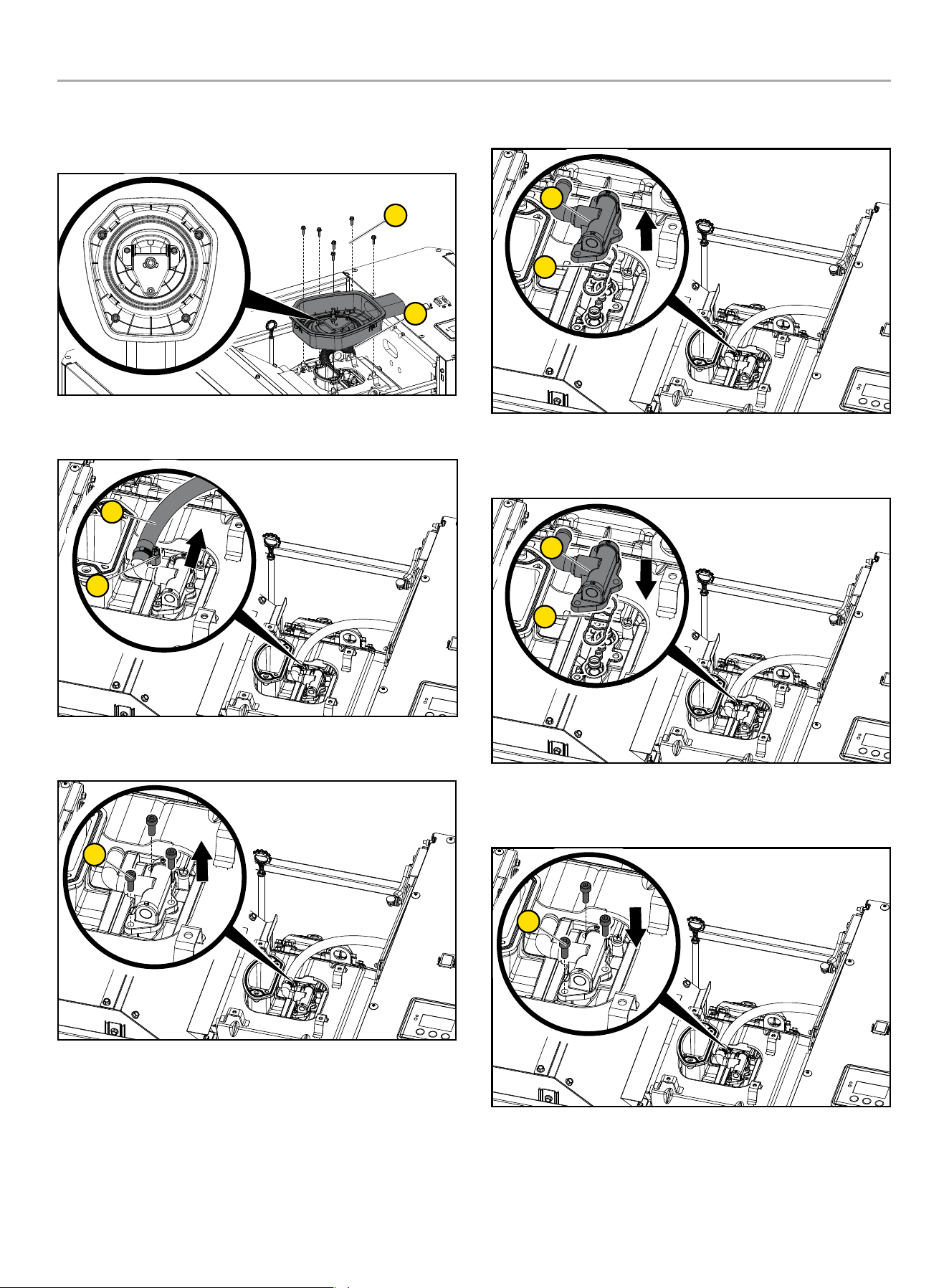
5. CONVERTING TO LPG
Jet Change Procedures - 22-kW (Model 201202)
The engine is fitted with a dual Master Mixer Assembly (carburetor
system), which allows the HSB to run on either NG or LPG. It has
been configured at the factory to run on NG. If your installation
requires to run on LPG, you need to exchange the Master Mixer
Assembly (carburetor system). This Master Mixer Assembly is
included for LPG conversion. Place a rag in the valley of the engine
to prevent damaging other components from any dropped parts.
After removing the air cleaner base, place a rag around the base
of the mixer assembly in case an o-ring, gasket or screw drops.
Tools Required:
– 4 mm hex bit socket or 4 mm T-Handle hex key - 4 mm allen
wrench is included.
– Ratchet Wrench for bit socket
– 10mm wrench or ratchet
– Torque wrench
1. Press the OFF button on the fleX Controller™.
2. Put the generator ON/OFF switch in the OFF position.
3. Remove the fuse from the front of the fleX Controller™. This
will disable automatic starting in the event of a power outage.
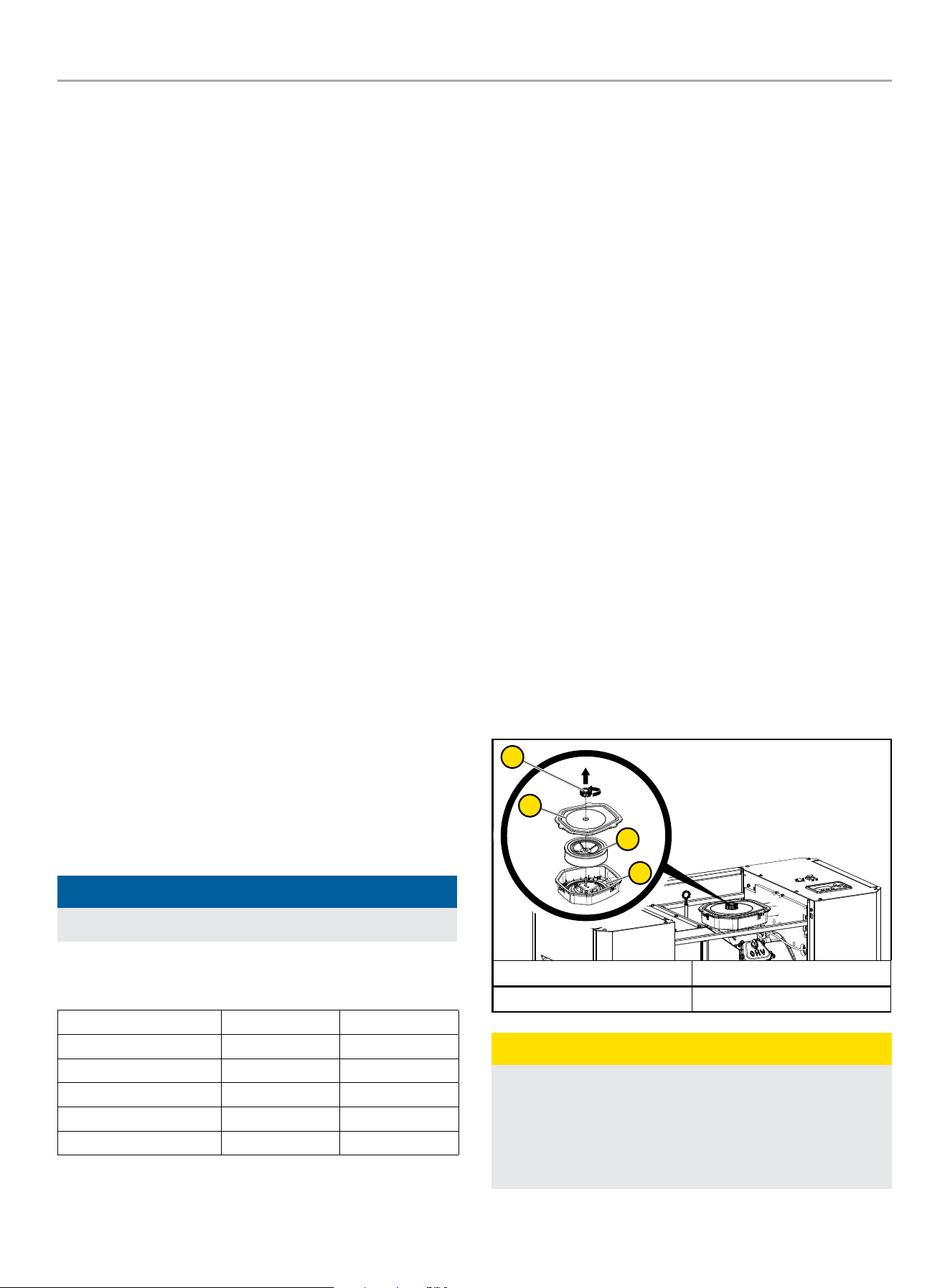
4. Open the top cover to gain access to the air filter.
5. Unscrew the air filter screw cap holding the air cleaner cover
in place and remove the air cleaner cover. Check the air
cleaner gasket is in good shape, if not replace the gasket.
6. Remove the air cleaner paper element and set aside.
1
2
4
3
A. Air filter screw cap B. Air cleaner cover
C. Paper element/foam filter D. Air Cleaner Base
CAUTION
Before removing the air filter base, place a rag in the intake to
prevent any parts from falling inside the engine.
After removing the air cleaner base, place a rag around the
base of the mixer assembly in case an o-ring, gasket or screw
drops.
HOME STANDBY GENERATOR- ALL fleX CONTROLLER™ MODELS
INSTALLATION
29
7. Remove (5) six [6] M6 bolts with 10mm socket to remove air
filter base (6).
* Do not remove highlighted nut.
5
6
8. Remove fuel line (7) by loosening fuel line clamp (8) with 7
mm or 9/32” socket.
7
8
9. Remove three [3] fuel inlet chamber cap head bolts (9) with
4mm or 5/32” allen wrench.
9
10. Remove Master Mixer Assembly (10) along with the gasket
(11).
10
11
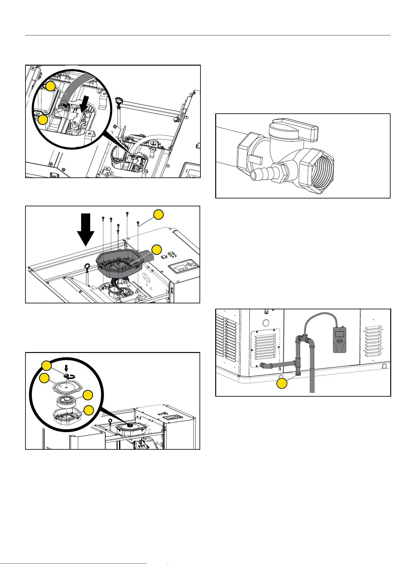
11. Install Master Mixer Assembly (10) with the green dot (this
indicates LPG) to mixer body. Make sure the gasket (11) is
installed on the fuel inlet chamber side.
10
11
12. Tighten Master Mixer Assembly three [3] cap head bolts
(9) with 4mm or 5/32” allen wrench. Torque: 26.0 lb.-in
(2.94Nm)
9
HOME STANDBY GENERATOR- ALL fleX CONTROLLER™ MODELS
INSTALLATION
30
13. Connect the fuel hose (7) to master mixer assembly and put
clamp (8) on fuel hose.
7
8
14. Reinstall (5) six [6] M6 bolts with 10mm socket to reinstall air
filter base (6).
5
6
15. Install paper element plus air cleaner foam element as one
piece back in the air cleaner base.
16. Replace air filter cover and screw the air filter screw cap
holding the air cleaner cover on.
1
2
4
3
17. Reinstall fuse removed in the earlier step back into the fleX
Controller™.
18. Put the generator ON/OFF switches in the ON position.
19. Put the fleX Controller™ to the previous position (either
Manual/ON, OFF or AUTO for example).
6. FULL FUEL SHUT OFF
A minimum of one accessible, approved manual full fuel shutoff
valve shall be installed in the fuel supply line of the HSB. A manual
full fuel shut off valve should be installed inside the building, for
those locations with inside gas meters. The full flow shut off valve
should be installed in accordance with all applicable codes and
standards.
7. SEDIMENT TRAP
A sediment trap should be installed into the fuel supply line
pipe when using either NG or LPG to drain any condensation.
Always make sure the HSB is completely in the OFF position and
the full flow fuel shut off valve is closed before removing the
sediment trap for drainage. Use a pipe sealant or joint compound
approved for use with LPG/NG on all threaded fittings to reduce
the possibility of leakage. Install a sediment trap (1) downstream
of the HSB shut-off valve as close to the inlet as possible in
accordance with local codes.
1
8. CHECKING PRESSURE WITH A MANOMETER
This check should only be done when the HSB and ATS have been
installed, properly inspected and ready for testing.
A Manometer is a general term for any device that measures
pressure. A gas manometer (1) measures gas pressure. It’s
important to make sure the correct amount of fuel is being
delivered to the HSB when it starts and at full load usage, the
Manometer provides the ability to check the fuel pressure
throughout the operation of the HSB. A Manometer port should be
placed in the fuel supply pipe line.
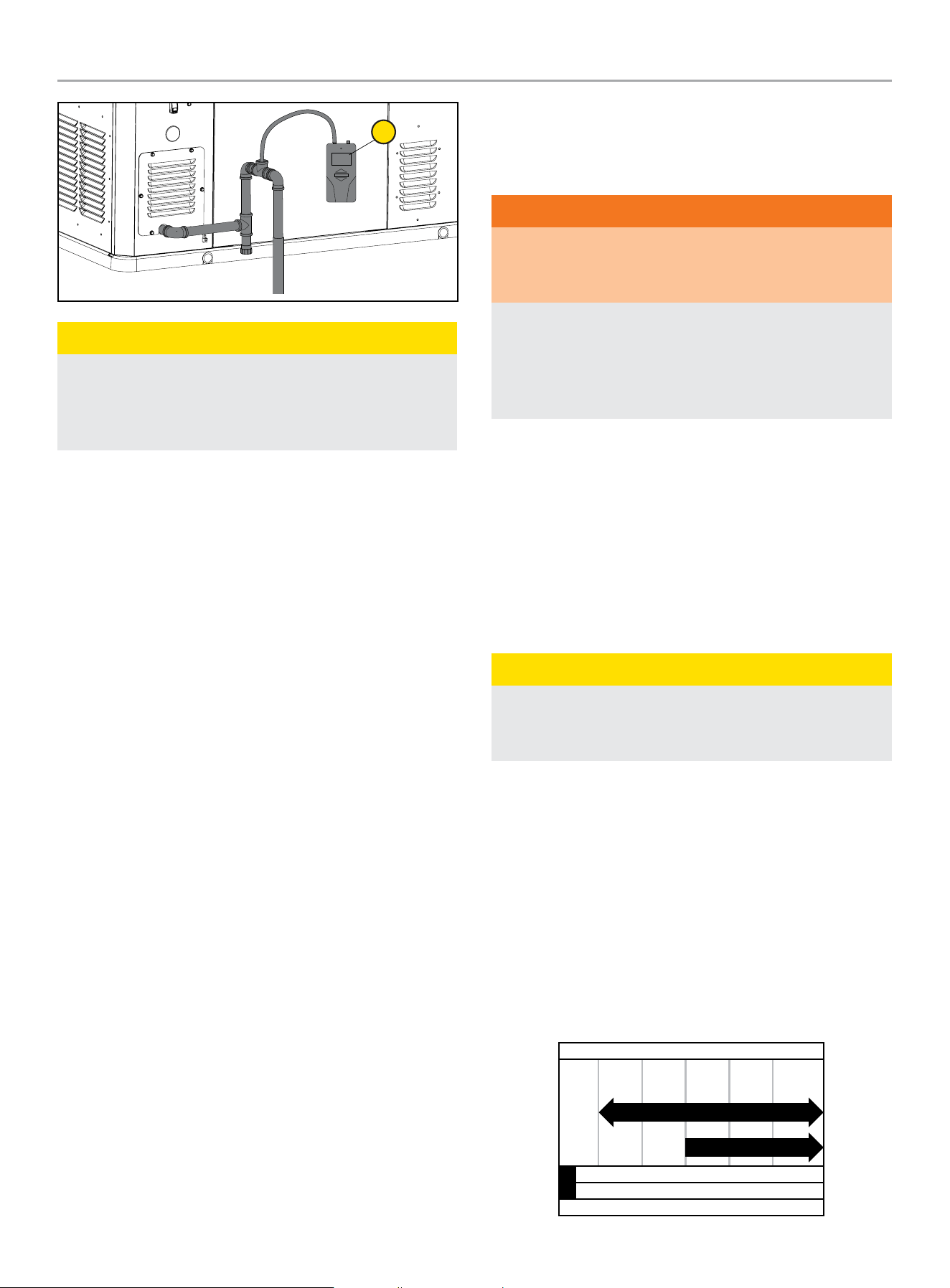
HOME STANDBY GENERATOR- ALL fleX CONTROLLER™ MODELS
INSTALLATION
31
1
CAUTION
Remove the plug, install the Manometer. Open the gas
supply valve check to make sure the pressures are within the
specified values for NG or LPG. This is always a good starting
point for evaluations related to poor performance.
After all appliances have been turn on, start the HSB. If the
Manometer stays within 5 -7 inches of water column for NG,
10 -12 inches of water column for LP, with full load applied to a
proper running HSB, the installation is good.
If the Manometer reading falls below the listed inches of water
column for either specific gas rating while the HSB engine is
starting or running. It may be an indication that the gas meter or
primary regulator is undersized.
If the Manometer reading stays within the specific gas rated
inches water column, but the HSB engine will not start, run erratic,
it may indicate insufficient fuel volume due to long fuel supply pipe
line, incorrect full pipe diameter. Recheck you initial calculations to
ensure where the problem might exist. Champion HSB units have
been run and tested at the factory. They do not require any type of
break-in period.
9. BATTERY REQUIREMENTS, INSTALLATION & SERVICE
Battery sizing is a topic that is discussed and debated for a
number of reasons. The battery size, cold cranking amps (CCA),
starting cycle or deep cycle are all items for consideration. The
following will assist you to better understand the battery, the
codes and the purpose of the battery. It is extremely important
to follow all cautions and warnings per the battery manufacturer
concerning installation, service, maintenance and replacement
procedures.
Battery Council International (BCI) is an association of battery
industry companies whose members establish policy and
standards for the industry.
Battery Size is the physical dimensions of a battery. BCI assigns
letters and numbers for North American battery size types.
Cold Cranking Amps (CCA) is a rating that is used to define
the batteries ability to start an engine under low-temperature
conditions. BCI defines it as “the number of amps a lead-acid
battery at 0 degrees F can deliver for 30 seconds”.
Starting (cranking) Cycle Battery is designed to deliver large
bursts of power for a short time, as needed to start an engine.
Starting batteries are intended to have a low depth of discharge on
each use.
WARNING
The starting system is a 24-volt DC system. The two 12-volt
batteries MUST be wired in series to achieve the correct
voltage.
Damage will result if the battery connections are made in
reverse, refer to owner manual or installation manual for
typical installation. Dielectric grease should be applied on
battery posts to aid in prevention of corrosion. Cables supplied
with the HSB.
This HSB is equipped with an automatic float type battery trickle
charger powered by utility power, to maintain full battery power
while in standby (non-running) mode. This trickle charger will not
recharge a fully discharged or defective battery.
When doing any work on the batteries always make sure the HSB,
ATS and transfer switch from utility are in the “OFF” position
or sparking may occur at the battery posts as the cables are
attached and cause an explosion.
Battery Requirements
CAUTION
For battery installation, maintenance, and safety requirements
refer to battery manufacturer’s battery installation and safety
manual.
22-kW (Model 201202)
Install two (2) 12 volt Group 51 batteries with maximum overall
dimension of 9 3/8 x 5 1/16 x 8 ¾ in. (238 x 129 x 223 mm)
L x W x H with an Automotive (A) post or terminal configuration.
Purchase batteries locally.
The recommended battery type for typical use is 500 CCA (Cold
Cranking Amps). However, a 435 CCA battery shown in the
Recommended Battery Type chart may be used for typical use, if
in a regularly warmer climates.
Alternatively, you may also use two (2) 12 volt Group 51R, but both
batteries must be 51R.
-40 -4 32 68 104+
Ambient temperature
Recommended Battery Type
-40
°F
°C -20 0 20 40+
435 CCA min
500 CCA min
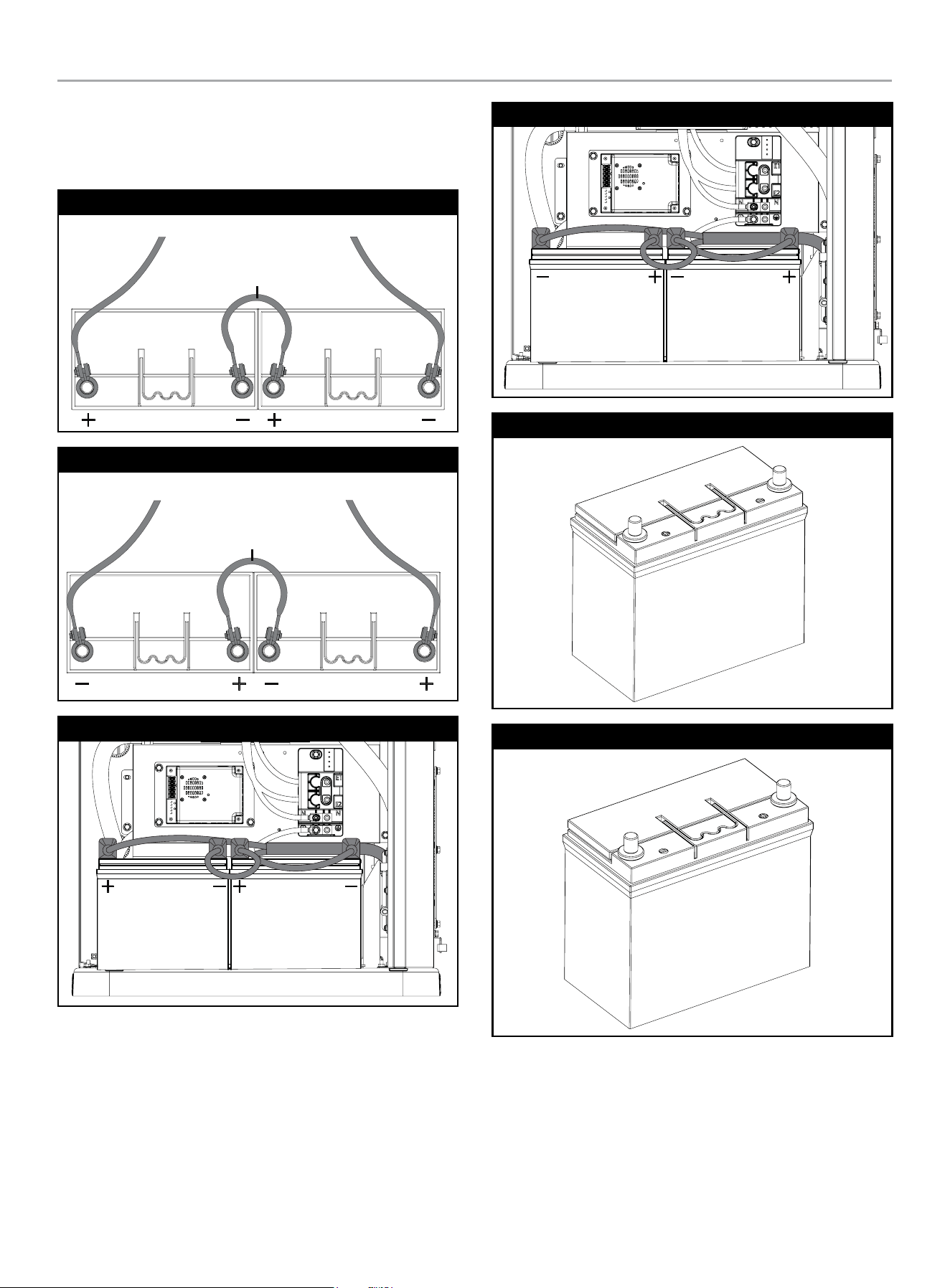
HOME STANDBY GENERATOR- ALL fleX CONTROLLER™ MODELS
INSTALLATION
32
Install positive cable first. Install a battery series cable from the
positive (+) terminal of one battery to the negative (–) terminal of
the other battery. Always connect the positive (+) battery cable to
the generator first.
Group 51 Automotive Post Style
TO STARTER TO GROUND
BATTERY SERIES CABLE
Group 51R Automotive Post Style
TO STARTERTO GROUND
BATTERY SERIES CABLE
Group 51
Group 51R
Group 51
Group 51R

HOME STANDBY GENERATOR- ALL fleX CONTROLLER™ MODELS
INSTALLATION
33
CAUTION
A battery presents a risk of electrical shock and high short
circuit current.
The following precautions are to be observed when working on
batteries:
1. Remove watches, rings, or other metal objects.
2. Use tools with insulated handles.
3. Wear rubber gloves and boots.
4. Do not lay tools or metal parts on top of the battery.
5. Disconnect charging source prior to connecting or
disconnecting battery terminals.
6. Determine the battery is inadvertently grounded. When
inadvertently grounded, remove source of ground. Contact
with any part of a grounded battery is capable of resulting
in electrical shock. The risk of such a shock is reduced
when such grounds are removed during installation and
maintenance (applicable to a generator not having a
grounded supply circuit.
WARNING
Do not dispose of battery or batteries in a fire. The battery is
capable of exploding.
WARNING
Do not open or mutilate the battery or batteries. Released
electrolyte has been known to be harmful to the skin and eyes
and can be toxic.
Vented Batteries
The installation of the engine generator shall provide enough
ventilation to ensure that all gases generated by vented batteries
during charging, or caused by equipment malfunction are
removed.
Battery Charger
CAUTION
For battery installation, maintenance, and safety requirements
refer to battery manufacturer’s battery installation and safety
manual.
This automatic battery charger is an intelligent module which
maintains lead acid batteries at a full charge, when the HSB has
been properly installed. Continual monitoring and maintenance
will promote long battery life. In accordance with the principle of
high efficiency, at Full Load, >85% of efficiency is achieved. This
charger is a maintenance battery charger. If the battery voltage
falls below 6V, the charger will not re-change the batteries.
To properly maintain battery efficiency, you must follow the
battery manufacturers; safety instructions, warnings and proper
maintenance procedures.
The battery(s) might be discharged to a level that is too low to
recharged with this charger (battery voltage below 6V). If this
is the case, the batteries will need to be charged individually.
Remove all battery cables from the batteries and follow the
battery manufacturers’ instructions on properly servicing/charging
the batteries.
Be careful to avoid corrosion on the battery post(s). Corrosion
can have the effect of creating an insulation between the post(s)
and the cable(s), this will severely affect the performance of the
battery.
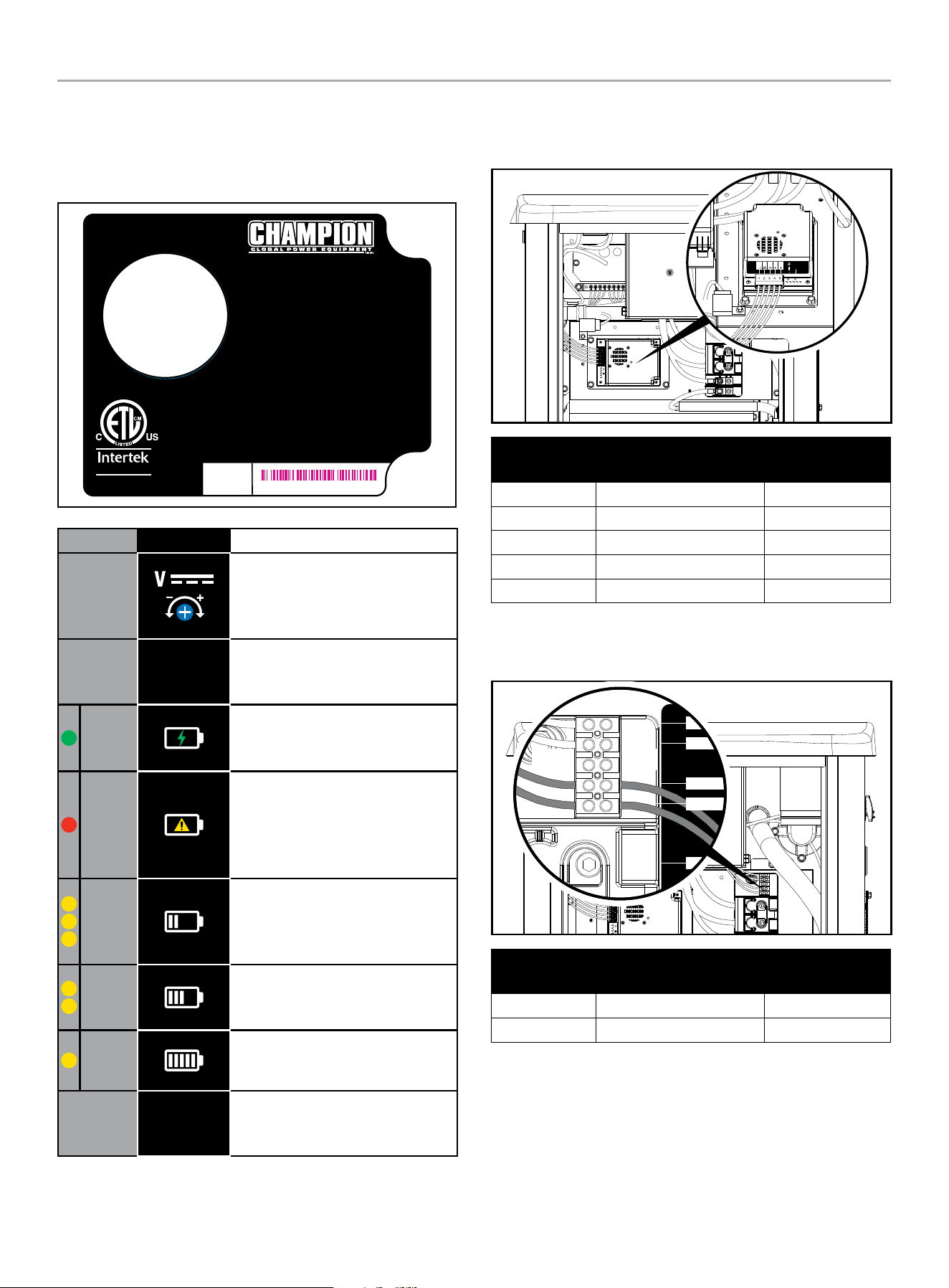
HOME STANDBY GENERATOR- ALL fleX CONTROLLER™ MODELS
INSTALLATION
34
22-KW (MODEL 201202)
The LEDs on the battery charger indicate whether the charger has
120VAC power, if there is a battery fault and the charger state.
Battery charger rating 24 VDC 7 A.
RECOGNIZED
COMPONENT
5027556
Certified to CSA Std. C22.2 NO.107.2
Conforms to UL Std.1236
4324-L-PR-B
AUTOMATIC BATTERY CHARGER
CHARGE AUTOMATIQUE DE BATTERIE
CARGADOR DE BATERÍA AUTOMÁTICO
For use with lead acid (LA/SL A), AGM, or Gel batteries.
Not for use with Lithium-ion batteries.
Pour une utilisation avec des batteries au
plomb-acide (LA / SLA), AGM ou gel.
Ne pas utiliser avec des batteries au lithium-ion.
Para uso con baterías de plomo ácido (LA/SLA), AGM o gel.
No para uso con las baterías de iones de litio.
INPUT: 80 - 125 VAC MAX 4.4 A 50/60 Hz
ENTRÉE : 80 - 125 VCA MAX 4,4 A 50 / 60 Hz
ENTRADA: 80 - 125 VCA MAX 4.4 A 50/60 Hz
OUTPUT: 24 VDC 7 A
SORTIE : 24 VCC 7 A
SALIDA: 24 VCC 7 A
SERIAL NO.
NO. DE SERIE
N° DE SÉRIE
MODEL / MODÈLE / MODELO #102652
XXXXXXXXXXXX
LED SYMBOL DESCRIPTION
DC Voltage Adjustment - Preset
from the factory for proper DC
charger output. No adjustments
necessary.
E. O.
Enforced Output - Press to charge
battery at maximum amperage for
a short period.
Green
Power - Lit to indicate the charger
is receiving 120 VAC and is ready
to charge.
Red
Fault or No Charge - Lit to indicate
a battery charging problem. If
this LED is lit, the LED on the fleX
Controller
™
, “LOW BATTERY” will
also be lit.
Yellow
High Charge - Lit to indicate the
charger is operating above 50%
capacity. Trickle charge and mid
charge LED will also be lit.
Yellow
Mid Charge - Lit to indicate the
charger is near 50% capacity.
Trickle charge LED will also be lit.
Yellow
Trickle Charge - Lit to indicate the
battery is receiving a trickle charge.
No Yellow
Low Trickle Charge - When no
yellow LEDs are lit, the charger is in
low trickle charge state.
A 120 VAC circuit must be installed for battery charging. From ATS
fuse block or distribution panel install 120V circuit to the terminal
block L and N.
4
5
1
2
3
4401-L-PR-A
V
– +
E.O.
Wire Land
Points
Function Wire Color
Wire land #1 L R (Red)
Wire land #2 N W (white)
Wire land #3 Ground G/Y (Green/Yellow)
Wire land #4 + R (Red)
Wire land #5 - B (black)
The terminal block is prewired by the factory to the charger L and
N. A 120 VAC circuit must be installed for battery charging from
the ATS or another 120VAC circuit.
2-Wire
COM
N
L1
L
INPUT
120V- N/L
OUTPUT-
CHARGER
Wire Land
Points
Function Wire Color
Wire land #1 L R (Red)
Wire land #2 N W (white)
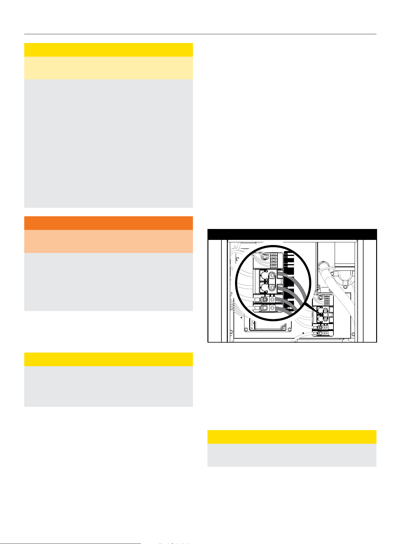
HOME STANDBY GENERATOR- ALL fleX CONTROLLER™ MODELS
INSTALLATION
35
CAUTION
The electrolyte is a diluted sulfuric acid that is harmful to the
skin and eyes. It is electrically conductive and corrosive.
The following procedures are to be observed:
1. Wear full eye protection and protective clothing.
2. Where electrolyte contacts the skin, wash it immediately
with water.
3. Where electrolyte contacts the eyes, flush thoroughly
and immediately with water and seek medical attention,
and spilled electrolyte is to be washed down with an acid
neutralizing agent. A common practice is to use a solution
of one pound (500 grams) bicarbonate of soda to one
gallon (4 liters) of water. The bicarbonate of soda is to be
added until the evidence of reaction (foaming) has ceased.
The resulting liquid is to be flushed with water and the
area dried.
WARNING
Lead-acid batteries present a risk of fire because they
generate hydrogen gas.
The following procedures are to be followed:
1. DO NOT SMOKE when near batteries.
2. DO NOT cause flame or spark in battery area, and
3. Discharge static electricity from body before touching
batteries by first touching a grounded metal surface.
10. WIRING OF THE HSB
Wire Sizing
CAUTION
Use a torque wrench to tighten conductors, being sure not to
overtighten, or damage to the switch base could occur. If not
tightened properly, a loose connection would result, causing
excess heat which could damage the switch base.
All installations must comply with National, State and Local codes.
It is the responsibility of the installer to perform an installation that
will pass the final electrical inspection. Conductor wire sizes must
be adequate to handle the maximum current to which they will be
subjected. The installation must comply fully with all applicable
codes, standards, and regulations.
All power cables must enter the enclosure through the knockouts
provided. If not using knockouts, conduit entry into the enclosure
must be at or below knockouts to maintain the Type 3R rating.
NEMA 3R enclosures are rated and tested for outside installation,
they are waterproof enclosures and only come with knockouts on
the bottom side of the enclosure. If a NEMA 3R enclosure in used
for an inside installation, a greenlee type punch will be required to
make a knockout(s) on the side or top of the enclosure.
Conduits should be arranged to provide separation between
the Utility Source and HSB Source supply conduits inside the
enclosure. Conductor wires must be properly supported, of
approved insulated qualities, protected by approved conduit and
of the correct wire gauge size in accordance with all applicable
codes.
Final inspection may require the installation of an emergency
shut down switch, installed and located where Home Standby
Generator Engine (prime mover) can be shut down instantly.
Verify that the (4) pre-installed 14-2 conductor lugs are free of
corrosion and are fully fastened and spaced properly. Make sure
conductor wires are labeled and/or marked accordingly.
22-kW (Model 201202)
4426-L-PR-A
2-Wire
COM
N
L2
L
N
L1
Utility Circuit and Generator Power Connections
Conductor sizes must be adequate to handle the maximum current
to which they will be subjected to, based on the 75 degrees
C column of tables, charts, etc. used to size conductors. The
installation must comply fully with all applicable codes standards
and regulations.
Surge protection
CAUTION
Voltage fluctuation may impair the proper functioning of
sensitive electronic equipment.
Electronic devices, including computers and many programmable
appliances use components that are designed to operate within a
narrow voltage range and may be affected by momentary voltage
fluctuations. While there is no way to prevent voltage fluctuations,
you can take steps to protect sensitive electronic equipment.

HOME STANDBY GENERATOR- ALL fleX CONTROLLER™ MODELS
INSTALLATION
36
Install UL1449, CSA-listed, plug-in surge suppressors on the
outlets feeding your sensitive equipment. Surge suppressors come
in single or multi-outlet styles. They’re designed to protect against
virtually all short-duration voltage fluctuations.
AVR / ASR = Automatic Voltage Regulator /
Speed Regulator (2 in 1)
AVR is a voltage regulator, which can automatically keep the
voltage within the specified range required by electrical equipment
powered by HSB. AVR uses solid-state semiconductor devices
to smooth the change of current; AVR monitors the output
voltage and controls the input voltage of the generator exciter. By
increasing or decreasing the generator control voltage, the output
voltage of the generator increases or decreases accordingly. AVR
will calculate how much voltage needs to be sent to the exciter
for countless times every second, to stabilize the output voltage
at a predetermined set point; ARV has the functions of off-line
protection, excitation short-circuit protection and overvoltage
flameout protection.
ASR is an electronic governor or speed regulator, which
automatically maintains the engine speed within a predetermined
range. ASR uses NTC for temperature monitoring to solve the
control problem that it is not easy to start because of low ambient
temperature. ASR is to monitor and control the engine speed,
and there are two startup modes, namely, idle mode and normal
startup mode. ASR has four functions, namely, idle function
in idle mode, cold start function in normal start mode, normal
temperature start function, and overspeed flameout protection
function. Idle function: when idle mode is selected, control the
engine to run at 40Hz (2400 RPM); Cold start function: when
the temperature is detected to be lower than -18°C, it will
automatically enter this mode. After entering this mode, the
engine will run at the frequency of 40Hz for 60 seconds, then
at the frequency of 50Hz for 20 seconds, and finally enter the
rated operating frequency of 60Hz; Normal temperature starting
function: when the temperature is detected to be greater than
-18°C, it will automatically enter this mode, and after entering this
mode, it will control the engine to directly enter the rated operating
frequency of 60Hz; Overspeed flameout function: when the engine
overspeed is monitored, the engine is controlled to flameout; After
the overspeed protection frequency is greater than or equal to
72Hz and lasts for 2 seconds, control the engine to turn off.
The AVR/ASR 2-in-1 control module has a total of 5 connections:
A. Sampling and excitation winding - 4 wires – 4 pins – top
left. The two wires on the left side of the connector are gray
(top) and white (bottom), which are connected to the sampling
winding on the stator. The two wires (top and bottom) on the
right side of the connector are blue, and they are connected
to the excitation winding on the stator.
B. Stepper motor - 4 wires - 4 pins – middle left. The four
wires from top to bottom of the connector are blue, yellow,
orange, and pink, which are directly connected to the
stepping motor on the carburetor, and the throttle opening is
controlled by the stepping motor.
C. Multiple power supplies and signal controls – 4 wires
– 6 pins – bottom left. The two wires on the left side of the
connector are black (top) connected to the negative pole of
24V power supply and red (bottom) connected to the AVR
power supply control port of HSB controller; Two wires in the
middle of the connector are blue (top) connected to the trigger
pole of the ignition coil and green (bottom) connected to the
flameout control port of the ignition coil; The two wires on the
right side of the connector are gray (top) idle signal control
(standby) and empty.
D. Current transformer – 3 wires – 3 pins. The three wires of
the connector are red (left), empty (middle) and black (right).
They are directly connected to the current transformer, and
the voltage curve under load is adjusted through the current
transformer.
E. Current transformer - 2 wires – 2 pins. The two wires of
the connector from top to bottom are red (top) and black
(bottom) respectively connected to the positive pole of the
brush assembly, and the brush assembly provides excitation
current to the rotating rotor. The brush is made of durable
materials and rarely wears or fails. The contact points of the
brush assembly are two slip rings attached to the rotor, which
may lose luster, thus causing resistance to the current, which
may be caused by the fact that HSB is not running or stored
for a long time.
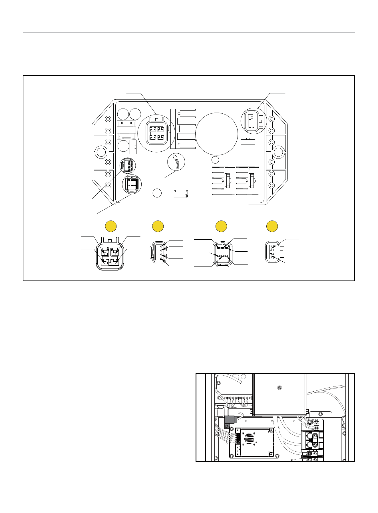
HOME STANDBY GENERATOR- ALL fleX CONTROLLER™ MODELS
CONTROLS AND FEATURES
37
CONTROLS AND FEATURES
AVR/ASR - Automatic Voltage Regulator / Electric Speed Regulator (2 in 1)
A
B C D
A
D
NTC
B
C
SMPL WDG
SMPL WDG
(Grey)
(White)
EXC WDG
Blue
DC-
(Black)
SPEED
(Blue)
DC+
Blanking
(Red/White)
NC
NC
EXC +
(Red)
EXC +
(Black)
(Green)
Yellow
Orange
Pink
EXC WDG
(Blue)
(Blue)
A. Sampling and excitation winding
B. Stepper motor
C. Multiple power supplies and signal controls
D. Brush and excitation
ATS Transfer Fuse
The system is protected by a 35A automotive style fuse. This
fuse, which can be blue-green or green, comes into play when
the Automatic Transfer Switch (ATS) transfers between utility
and generator or vice versa. Conveniently located just above the
battery charger, it’s easy to access by removing the fuse cover.
In case of a fuse failure, replace the fuse with one of identical
amperage and type.
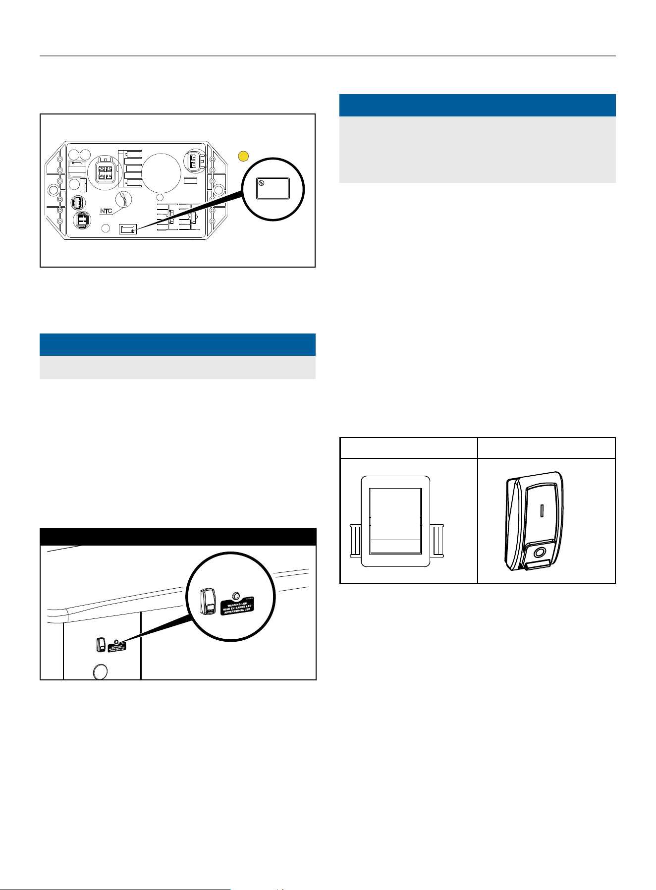
HOME STANDBY GENERATOR- ALL fleX CONTROLLER™ MODELS
CONTROLS AND FEATURES
38
Potentiometer
There is one potentiometer - voltage regulator.
W 202
WK 4 1
A
A. Voltage regulator - adjust the voltage to the rated voltage
(240V, which can also be adjusted according to the actual
situation of customers), and the voltage jump value is ≤±1V.
NOTICE
The voltage regulator potentiometer is set at the factory.
Exterior Warning LED
The exterior of the generator enclosure includes a Warning LED
that illuminates RED when a fault has occurred.
The Warning LED provides a visual indicator to homeowners
and service technicians that a fault has occurred, and service is
needed.
The warning LED is located on the back-exterior of the HSB.
22-kW (Model 201202)
Generator ON/OFF Switch
NOTICE
When maintenance or service work is performed on the
generator or the home’s electrical system, to prevent
accidental startup pull out the fuse from the fleX Controller
™
panel and disconnect the batteries.
22-KW (MODEL 201202)
This generator has ON/OFF switches that when turned off, will
shut down the HSB (if running) and deactivate the fleX Controller
™
preventing future starts. These switches should be used in
instances where the HSB needs to stay off regardless of utility
power presence. When either switch is in the OFF position, the
HSB will not exercise or start for any reason.
When both of the switches are in the ON position, the fleX
Controller
™
will be energized and the HSB will be controlled by the
programming of the fleX Controller
™
. Both switches need to be in
the ON position in order for the HSB to operate in AUTO mode.
OTE: N Both switches need to be in the ON position to place the
fleX Controller
™
in the AUTO mode and in order to exercise
the HSB.
Inside Back
ON
OFF
ON
OFF
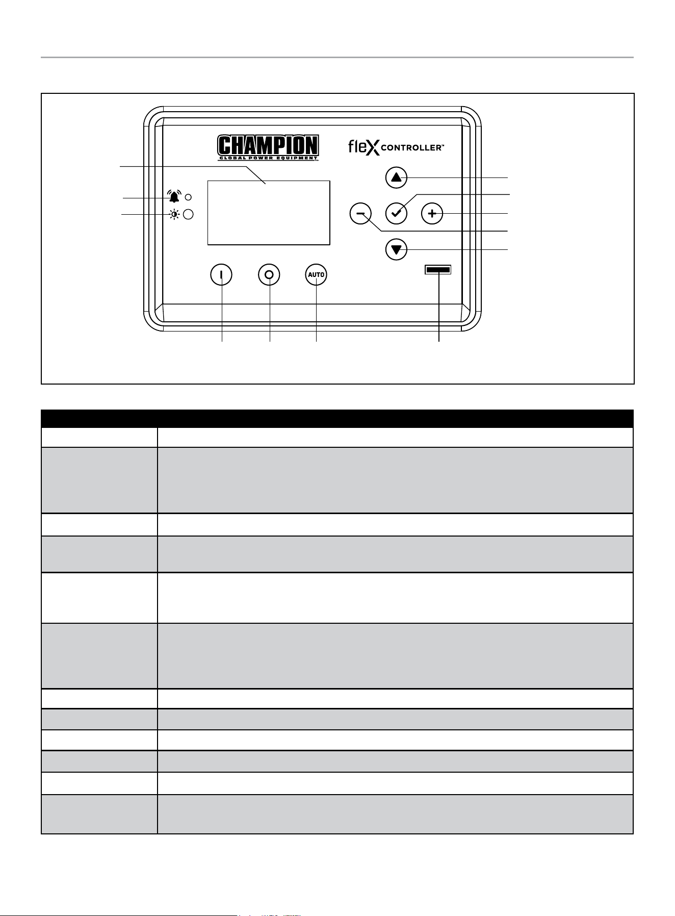
HOME STANDBY GENERATOR- ALL fleX CONTROLLER™ MODELS
CONTROLS AND FEATURES
39
fleX Controller
™
Display
Warning
PV
Manual /
ON
OFF Auto
Fuse
Up/Increase
Down/Decrease
Ok
Right
Left
The fleX Controller
™
provides real time monitoring, protection, information on the status and settings of the HSB.
Description
Display Shows settings and status of the HSB.
Warning
In all cases when the icon is RED, this is an indicator that the HSB has registered a fault and must be
corrected. Only the “LOW BATTERY” and “MAINTENANCE” icons will not latch out or shut down the HSB.
ALL other RED icon faults will latch out, shut down, disable starting and light the RED icon on the fleX
Controller
™
and the exterior warning LED on the backside of the HSB.
PV Photovoltaic (PV) sensor that detects environment light level and adjusts the screen brightness automatically.
Manual/ON
Press to start the HSB in Manual mode. Allows verification that the HSB power delivery circuit is functional.
The engine will start in manual mode. Safety procedures should be followed.
OFF
Press to stop the HSB in Manual or Auto mode. Closes and shuts down the engine signals. It prevents the
automatic operation of the generator. OFF is required when all maintenance or service is being performed on
or around the unit.
Auto
Press to put the HSB in Auto mode. When in Auto, this allows automatic delivery of power from the HSB
when there is a utility power outage. With the controller in the Auto and the HSB not running (standby mode),
this indicates the household is using utility power. Auto position is the standby ready position. The fleX
Controller
™
must be in the Auto mode in order to exercise.
Up/Increase Moves up in the lists of the various settings or increases variables.
Down/Decrease Moves down in the lists of the various settings or decreases variables.
Right Moves right in the lists of the various settings.
Left Moves left in the lists of the various settings.
Ok Confirms programming the fleX Controller
™
. Press and hold to enter settings pages.
Fuse
Protects the fleX Controller
™
and allow direct removal to keep the controller from engaging. Remove the fuse
while all maintenance or service is being performed on or around the unit.
HOME STANDBY GENERATOR- ALL fleX CONTROLLER™ MODELS
CONTROLS AND FEATURES
40
STATE
STATE variables in fleX Controller
™
. These are view-only, monitor variables.
Highlighted variables show up after the ATS is connected and powered.
TOP MENU
DESCRIPTION ON SCREEN
STATE
BATTERY VOLTAGE BATTERY VOLTS
CURRENT EVENT RUN TIME EVENT TIME
GENERATOR TOTAL HOURS TOTAL RUN TIME
VERSION VERSION
SERIAL NUMBER S/N
SYSTEM OUTPUT L1 AMPS AMPERAGE L1
SYSTEM OUTPUT L2 AMPS AMPERAGE L2
PHASE VOLTAGE (UTILITY, L1-N) UTILITY L1-N
PHASE VOLTAGE (UTILITY, L2-N) UTILITY L2-N
LINE VOLTAGE (UTILITY, L1-L2) UTILITY L1-L2
UTILITY FREQUENCY UTILITY Hz
PHASE VOLTAGE (GEN, L1-N) GENERATOR L1-N
PHASE VOLTAGE (GEN, L2-N) GENERATOR L2-N
LINE VOLTAGE (GEN, L1-L2) GENERATOR L1-L2
GENERATOR FREQUENCY GENERATOR Hz
LOAD VOLTAGE (LOAD, L1-N) LOAD L1-N
LOAD VOLTAGE (LOAD, L2-N) LOAD L2-N
LOAD VOLTAGE (LOAD, L1-L2) LOAD L1-L2
LOAD POWER (LOAD, L1-N) LOAD Power L1-N
LOAD POWER (LOAD, L2-N) LOAD Power L2-N
LOAD POWER (LOAD, L1-L2) LOAD Power L1L2
LOAD1 POWER LOAD1 Power
LOAD2 POWER LOAD2 Power
LOAD3 POWER LOAD3 Power
LOAD4 POWER LOAD4 Power
AC1 POWER AC1 Power
AC2 POWER AC2 Power
HOME STANDBY GENERATOR- ALL fleX CONTROLLER™ MODELS
CONTROLS AND FEATURES
41
User Settings
USER variables in fleX Controller
™
.
Highlighted variables show up after the ATS is connected and powered. See Programming fleX Controller™ for more information on initial
setup. Abbreviations may not match exact as shown on screen for units of measure. Follow the setting defaults for guidance.
For example, 60 seconds, would be shown as 60 sec. or 60s.
TOP MENU
DESCRIPTION ON SCREEN DEFAULT
USER SETTINGS
HOURS UNTIL MAINTENANCE IS REQUIRED NEXT SERVICE 100.0h
RESET SERVICE RESET SERVICE OFF
ENGINE START DELAY AFTER UTILITY LOSS BROWNOUT DELAY 30s
ENGINE COOLING TIME ENG COOL TIME 60s
LANGUAGE LANGUAGE english
SCREEN SLEEP TIME SLEEP DELAY 600s
SCREEN BRIGHTNESS BRIGHTNESS 100%
BOND MODE BOND MODE OFF
OVER THE AIR OTA
SYSTEM TIME (year) SYS year 2023
SYSTEM TIME (month) SYS month 12
SYSTEM TIME (day) SYS date 31
SYSTEM TIME (hour) SYS hour 0
SYSTEM TIME (minute) SYS minutes 0
SYSTEM TIME (second) SYS second 0
SYSTEM TIME (week) SYS week 6
DAYLIGHT SAVINGS TIME DST OFF
EXERCISE FREQUENCY EXERCISE FREQ None
EXERCISE DAY OF WEEK EXERCISE DAY 1
EXERCISE START (hour) EXER START H 0
EXERCISE START (minute) EXER START M 0
EXERCISE RUN TIME EXERCISE TIME 15min
HOME STANDBY GENERATOR- ALL fleX CONTROLLER™ MODELS
CONTROLS AND FEATURES
42
TOP MENU
DESCRIPTION ON SCREEN DEFAULT
ATS PARAM
ATS WAITING TIME
(UTILITY TO GENERATOR TO GENERATOR)
ATS SWITCH T UG 10s
ATS WAITING TIME (GENERATOR TO UTILITY) ATS SWITCH T GU 10s
UTILITY OVER VOLTAGE UTIL OVER VOLT 258V
UTILITY UNDER VOLTAGE UTIL UNDER VOLT 190V
UTILITY OVER FREQUENCY TIME UTIL OVER FREQ 66Hz
UTILITY UNDER FREQUENCY TIME UTIL UNDER FREQ 56Hz
UTILITY OVER VOLTAGE TIME UTIL OVER VOL T 500ms
UTILITY UNDER VOLTAGE TIME UTIL UND VOL T 10s
UTILITY OVER FREQUENCY TIME UTIL O FREQ T 1s
UTILITY UNDER FREQUENCY TIME UTIL U FREQ T 10s
UTILITY LINE VOLTAGE UTIL LINE VOLT 15V
GENERATOR OVER VOLTAGE GEN OVER VOLT 258V
GENERATOR UNDER VOLTAGE GEN UND VOLT 190V
GENERATOR OVER FREQUENCY GEN OVER FREQ 66Hz
GENERATOR UNDER FREQUENCY GEN UNDER FREQ 56Hz
GENERATOR OVER VOLTAGE TIME GEN OVER VOLT T 500ms
GENERATOR UNDER VOLTAGE TIME GEN UND VOLT T 10s
GENERATOR OVER FREQ TIME GEN O FREQ T 1s
GENERATOR UNDER FREQ TIME GEN U FREQ T 10s
GENERATOR LINE VOLTAGE GEN LINE VOLT 15V
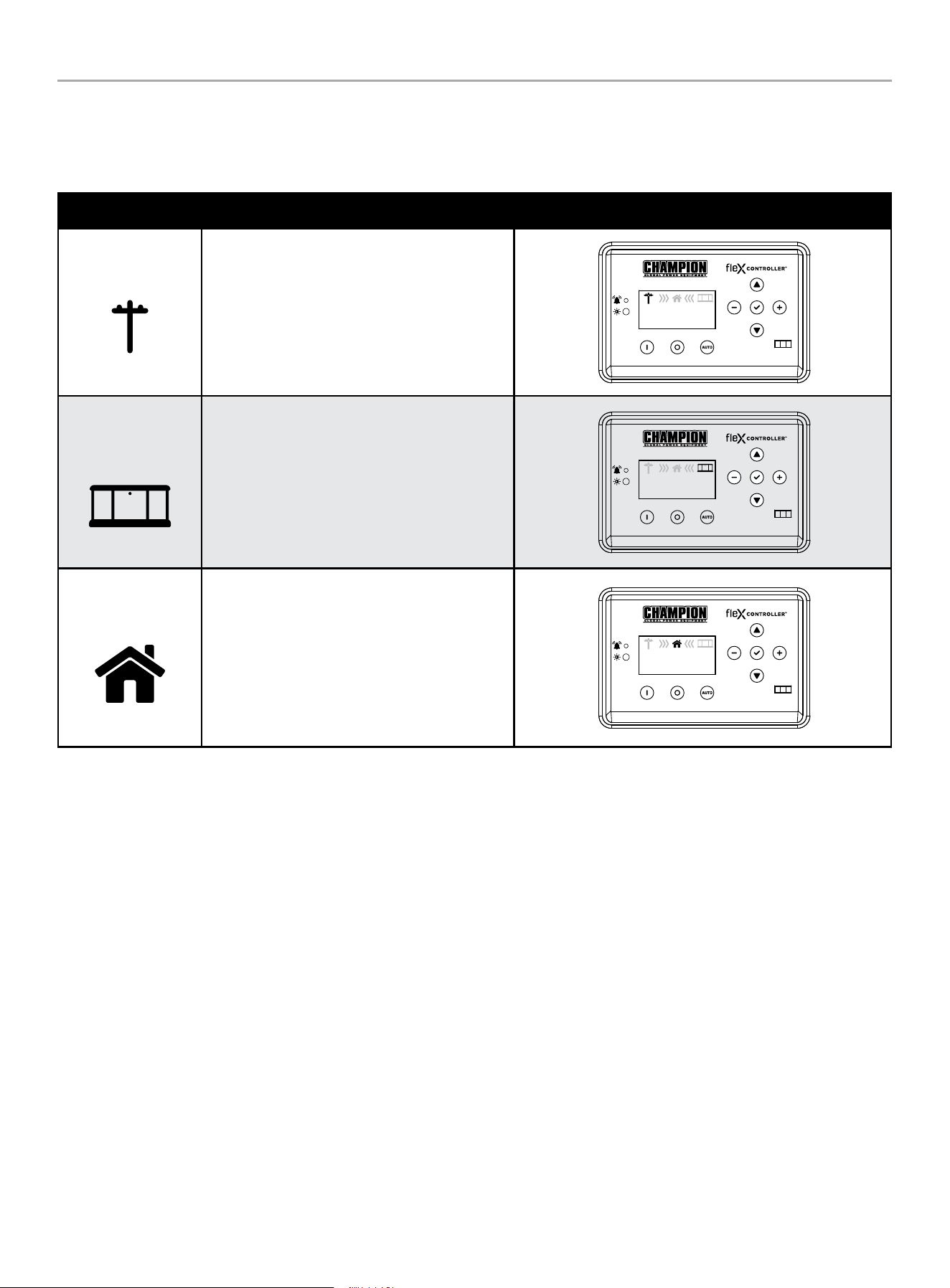
HOME STANDBY GENERATOR- ALL fleX CONTROLLER™ MODELS
CONTROLS AND FEATURES
43
Status Icons
The fleX Controller
™
displays status icons.
Utility, HSB, House Power
MODE DESCRIPTION
Utility
The utility pole icon indicates utility power.
AUTO
240.0V
60.0HZ
240.0V
60.0HZ
00-00
00:00
HSB
The HSB icon indicates the generator is running.
AUTO
240.0V
60.0HZ
240.0V
60.0HZ
00-00
00:00
Home
The home indicates your home is receiving power.
AUTO
240.0V
60.0HZ
240.0V
60.0HZ
00-00
00:00
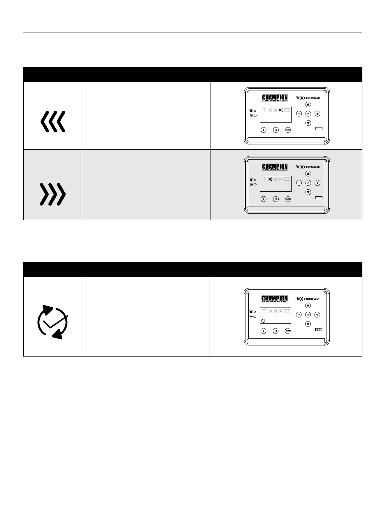
HOME STANDBY GENERATOR- ALL fleX CONTROLLER™ MODELS
CONTROLS AND FEATURES
44
Transfer Power Direction
Show the direction of power from HSB or from utility.
MODE DESCRIPTION
HSB Supplying Power
HSB is supplying power to the home.
AUTO
240.0V
60.0HZ
240.0V
60.0HZ
00-00
00:00
Utility Supplying
Power
Utility is supplying power to the home.
AUTO
240.0V
60.0HZ
240.0V
60.0HZ
00-00
00:00
Information Icons
The fleX Controller
™
displays information icons.
MODE DESCRIPTION
Exercise
The icon indicates when the HSB is performing
the exercise period. Refer to “Setting Exercise
Time” to establish the weekly exercise period.
When the exercise period is complete the icon
will turn off and the HSB will resume its standby
monitoring. The fleX Controller
™
must be in the
AUTO mode in order to exercise.
AUTO
240.0V
60.0HZ
240.0V
60.0HZ
00-00
00:00
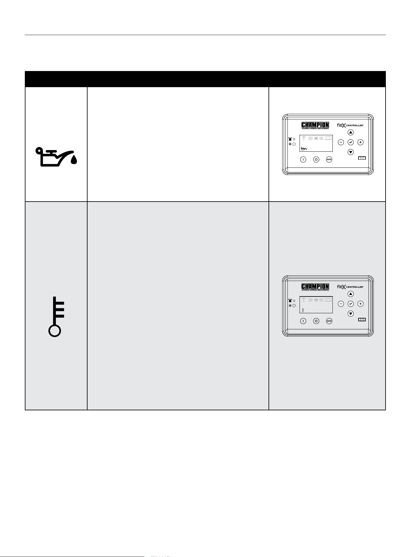
HOME STANDBY GENERATOR- ALL fleX CONTROLLER™ MODELS
CONTROLS AND FEATURES
45
Fault Icons
The fleX Controller
™
displays fault icons.
MODE DESCRIPTION
Low Oil Pressure
Shutdown
The icon will be lit when the engine oil pressure drops below a safe
operating level. When this fault is detected, the HSB will shut down
and re-start will be disabled. The warning LED on the controller and
exterior will be lit.
Check the oil level. The oil level should be at the FULL mark, if
necessary, add oil. DO NOT overfill. Inspect the unit for a possible
oil leak, if a leak is discovered, contact Champion or your nearest
Authorized Champion Dealer. Follow the FAULT CODE RESET
instructions to clear the fault after service.
AUTO
240.0V
60.0HZ
240.0V
60.0HZ
00-00
00:00
High Engine
Temperature
The icon will be lit if the engine operating temperature exceeds
the factory preset limits. If excessive operating temperature is
detected, the HSB will shut down and re-start will be disabled. The
warning LED on the controller and exterior will be lit.
This failure could be the result of an excessive load or high ambient
temperatures. Should this fault occur do the following:
1. Open the enclosure doors to increase air flow through the HSB.
2. Check oil level and add oil if required.
3. Inspect the interior and exterior of the enclosure for debris,
leaves, etc., and remove them to increase air flow around and
inside the unit.
4. Once the engine temperature falls into the normal operating
range, generally 30 minutes, follow the FAULT CODE RESET
instructions to clear the fault after service. Then, put the fleX
Controller
™
in AUTO mode.
5. Close the enclosure doors and the unit is ready to run.
AUTO
240.0V
60.0HZ
240.0V
60.0HZ
00-00
00:00
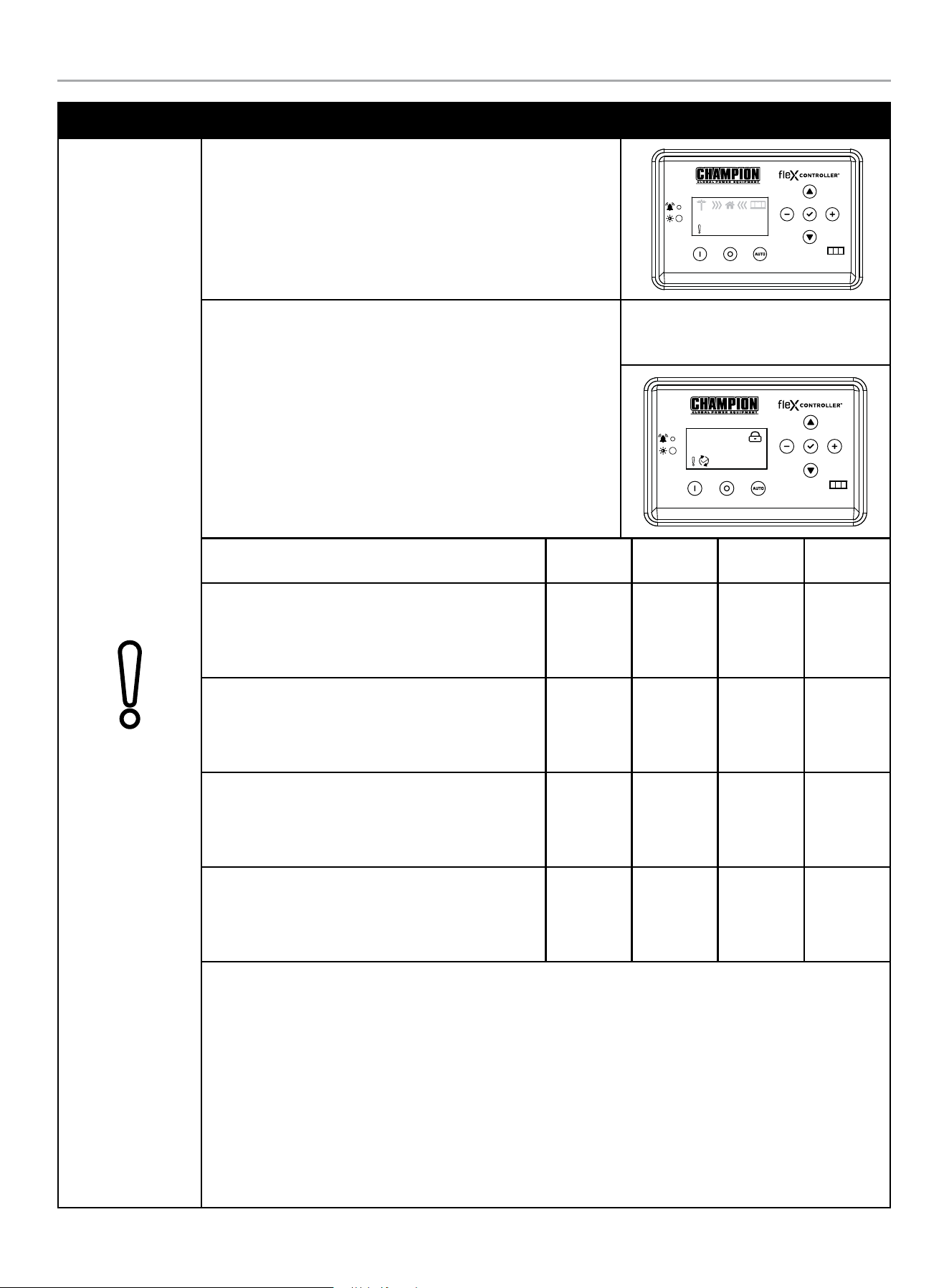
HOME STANDBY GENERATOR- ALL fleX CONTROLLER™ MODELS
CONTROLS AND FEATURES
46
MODE DESCRIPTION
Over Crank
The icon will be lit if the HSB does not start. This prevents the HSB
from damaging itself or other related components. When the fault is
detected, the HSB will shut down and re-start will be disabled. The
warning LED on the controller and exterior will be lit.
AUTO
240.0V
60.0HZ
240.0V
60.0HZ
00-00
00:00
STARTER CRANK CYCLE TIMES - If the HSB fails to start, the
“OVER CRANK” icon will flash on the fleX Controller
™
and a steady
lit exterior warning LED on the backside of the HSB. Below outlines
the crank cycle differences depending on the mode selected. Please
note there is a 120 second lockout or rest period after the cycles for
each mode listed to allow the starter to properly cool.
Follow the FAULT CODE RESET instructions by pushing the OFF
button to reset and clear the fault. Regardless of when you press
OFF, you will need to allow the timer to count down to zero (0)
before proceeding with another start procedure. The lockout time
remaining is shown on the display below the lock icon.
Example: AUTO mode, during exercise
with OVER CRANK fault. The timer upper
right is counting down 94 seconds.
AUTO
094s
Mode
ON
(seconds)
OFF
(seconds)
Cycles
Lockout
(seconds)
AUTO
The HSB is in the ready position. The fleX Controller
™
must be in the AUTO mode in order to exercise.
9 10 5 120
MAN
The HSB will start in MANUAL mode.
10 10 2 120
EXERCISE (PLC)
The HSB is connected to a Champion Automatic
Transfer Switch.
8 30 3 120
EXERCISE (2-wire)
The HSB is connected to a non-Champion Automatic
Transfer Switch.
9 10 5 120
This failure could also be the result of insufficient fuel supply. Check the in-line fuel shut off valves and make
sure they are in the ON/ OPEN position. Position them in the correct position, follow the FAULT CODE RESET
instructions to clear the fault after service.
If they are in the correct position and the HSB shows a fault light again, it’s recommended to perform a
Manometer pressure check by an Authorized Champion Dealer or installer. This will make sure the correct
amount of fuel is being delivered to the HSB when it starts.
Insufficient battery output could result in poor cranking cycles, not permitting the engine starter to reach
optimum starting RPM to start the engine. This can be verified by checking the Battery Charger icon, NO
CHARGE. If this occurs, the individual battery voltages must be checked to determine if the batteries are properly
charged or if they have failed. It is extremely important to follow all the cautions and warnings per the battery
manufacturer concerning installation, service, maintenance and replacement procedures.
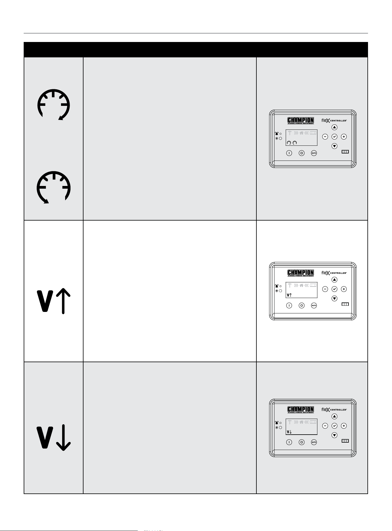
HOME STANDBY GENERATOR- ALL fleX CONTROLLER™ MODELS
CONTROLS AND FEATURES
47
MODE DESCRIPTION
Hz Over Speed
Under Speed
The icon will be lit if the engine was operating above or below its
preset speed limits. These limits are factory set to protect the HSB
and the circuits connected to the generator output circuits. When
this fault occurs, the HSB will shut down, light the warning icon,
shut down and re-start will be disabled. The warning LED on the
controller and exterior will be lit.
When this fault occurs, the HSB will shut down, light the warning
icon, shut down and re-start will be disabled. The warning LED on
the controller and exterior will be lit.
If this failure occurs, contact Champion or your Authorized
Champion Dealer. The icon will remain lit until the failure has been
corrected, the HSB will not attempt to transfer or run. Follow the
FAULT CODE RESET instructions to clear the fault after service.
AUTO
240.0V
60.0HZ
240.0V
60.0HZ
00-00
00:00
Line Over Voltage
This icon will be lit if the HSB generator output power exceeds
preset limits of 258-290 VAC and lasts 0.5 seconds. Alternatively, if
the greater than 290 VAC and lasts 0.03 seconds. Both cases occur
if running for 6 seconds the condition occurs.
When this fault occurs, the HSB will shut down, light the warning
icon, shut down and re-start will be disabled. The warning LED on
the controller and exterior will be lit. Check and adjust AVR. Set
voltage to 240 VAC.
If this failure occurs, contact Champion or your Authorized
Champion Dealer. The icon will remain lit until the failure has been
corrected, the HSB will not attempt to transfer or run. Follow the
FAULT CODE RESET instructions to clear the fault after service.
AUTO
240.0V
60.0HZ
240.0V
60.0HZ
00-00
00:00
Line Under Voltage
This icon will be lit if the HSB generator output power is below
preset limits of 190 VAC and lasts 0.5 seconds. This will occur if
running for 5 seconds the condition occurs.
When this fault occurs, the HSB will shut down, light the warning
icon, shut down and re-start will be disabled. The warning LED on
the controller and exterior will be lit. Check and adjust AVR. Set
voltage to 240 VAC.
If this failure occurs, contact Champion or your Authorized
Champion Dealer. The icon will remain lit until the failure has been
corrected, the HSB will not attempt to transfer or run. Follow the
FAULT CODE RESET instructions to clear the fault after service.
AUTO
240.0V
60.0HZ
240.0V
60.0HZ
00-00
00:00
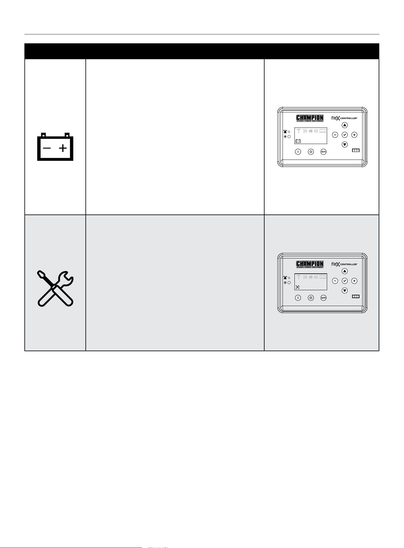
HOME STANDBY GENERATOR- ALL fleX CONTROLLER™ MODELS
CONTROLS AND FEATURES
48
MODE DESCRIPTION
Low Battery
This icon will be lit if the battery voltage falls below 21.0 volts for at
least 2 seconds while the engine is running. If the battery voltage
rises above 22 volts, the icon will turn off. Battery voltage is NOT
monitored when the engine is cranking, just when the engine is
running. If the icon comes on it will not shut the HSB off, it will
remain lit until the battery condition meets the required output.
When this fault occurs, the HSB will not shut down, light the
warning icon, the battery charging should be checked. The warning
LED on the controller and exterior will be lit.
The icon will remain lit until the failure has been corrected, the HSB
will continue to transfer or run until voltage drop causes fuel cut
solenoid to close. Follow the FAULT CODE RESET instructions to
clear the fault after service.
AUTO
240.0V
60.0HZ
240.0V
60.0HZ
00-00
00:00
Maintenance
This icon will be lit if the HSB requires maintenance.
The maintenance hour NEXT SERVICE meter counts from 100 hours
to 0. You need to reset when the hour meter reaches 0. Refer to the
scheduled maintenance chart.
The icon will remain lit until the failure has been corrected, the
HSB will continue to transfer or run. Follow the RESETTING THE
MAINTENANCE HOUR METER to clear the fault after service.
AUTO
240.0V
60.0HZ
240.0V
60.0HZ
00-00
00:00
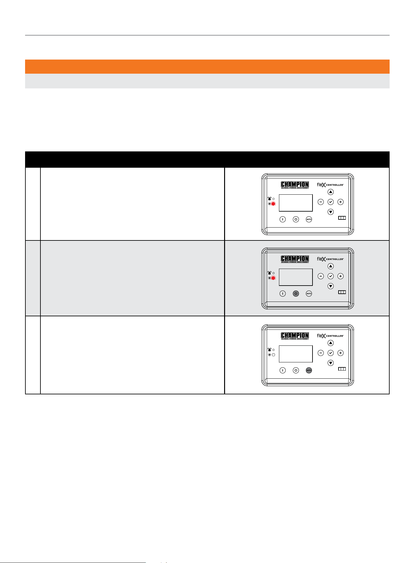
HOME STANDBY GENERATOR- ALL fleX CONTROLLER™ MODELS
CONTROLS AND FEATURES
49
Fault Protection
WARNING
All faults should be taken seriously and corrected before reset process is performed.
In all cases when the icon is lit, this is an indicator that the HSB has registered a fault and must be corrected. Only the “LOW BATTERY”
and “MAINTENANCE” icons will not latch out or shut down the HSB. ALL other icon faults will latch out, shut down, disable starting and
light the icon on the fleX Controller
™
and the exterior warning LED on the backside of the HSB.
Fault Code Reset
DESCRIPTION
1 In the event a fault has occurred
OFF
ARRET
2 Push OFF button to reset
OFF
ARRET
3 Then AUTO
MAN
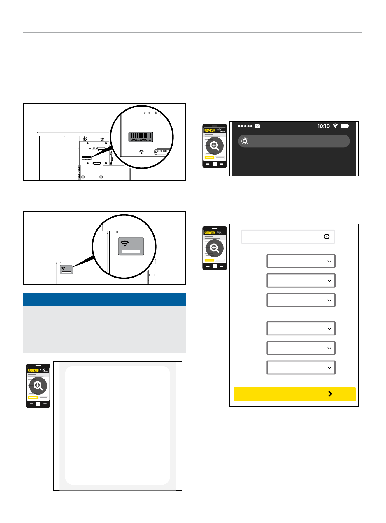
HOME STANDBY GENERATOR- ALL fleX CONTROLLER™ MODELS
CONTROLS AND FEATURES
50
Wi-Fi Setup Method
1. Use a Wi-Fi enabled device (laptop, smart phone, tablet, etc.)
in near proximity to the ATS.
2. Search and connect to network name (SSID) “Champion
####” where #### will match the last four digits of the serial
number that is printed on the control board.
2a. The password for the network is located on a label on the
dead front of the ATS.
PASSWORD
CONTRASEÑA
MOT DE PASSE
12345678
PASSWORD
CONTRASEÑA
MOT DE PASSE
12345678
NOTICE
During the setup your device will disconnect from the internet.
The Champion Wi-Fi is a direct connection between your
device (laptop, smart phone, tablet, etc.) and the ATS, and it
does not connect to the internet. Some Android devices may
show the following screen – Choose “Connect only this time.”
Internet may not be available.
If you want to connect this network without
internet access, you can connect only this
time or you can set your phone to always
connect to it even if internet isn’t available.
You can change this in Settings >
Connections > Wi-fi > ADVANCED >
Switch to mobile data > Network
exceptions
Connect only this time
Allow switch
Stay connected
3. After connecting Wi-Fi, open your device’s web browser. In
the browser address change the address to 192.168.0.90 and
begin search. This will direct your browser to the Champion
fleX Controller
™
Home Standby Generator Settings page
located on the ATS. If your device’s web browser does not
load the Champion fleX Controller
™
Home Standby Generator
Settings Page but rather stays connected to the internet, turn
off mobile data on the device (if applicable) and make sure
the device is not connected to any other networks.
192.168.0.90
4. On the Champion fleX Controller
™
Home Standby Generator
Settings Page, set the date and time. Use either the dropdown
boxes or the “USE THIS DEVICE DATE & TIME” button to set
the time and date.
USE DEVICE DATE & TIME
Date:
Choose Month...
Choose Date...
Choose Year...
Time:
Choose Hour...
Choose Minute...
Choose AM/PM...
CONFIRM DATE & TIME
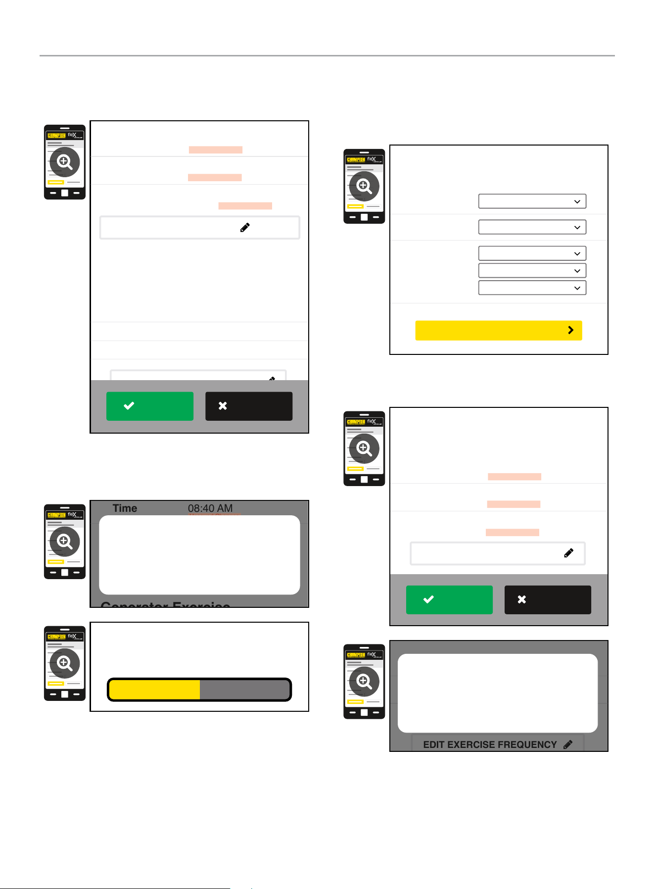
HOME STANDBY GENERATOR- ALL fleX CONTROLLER™ MODELS
CONTROLS AND FEATURES
51
5. Confirm and apply the settings before continuing. If you do
not apply immediately, the clock will be later than actual.
Unsaved changes are highlighted.
Generator Exercise
Every Week
Friday
09:00 AM
Frequency:
Day:
Time:
March 22, 2022
08:40 AM
On
Date
Time
Day Light Saving
Generator Date and Time
EDIT DATE & TIME
(Automated Maintenance Running)
EDIT EXERCISE FREQUENCY
Unsaved Changes
Unsaved Changes
Unsaved Changes
APPLY
REVERT
6. Some operating systems will require additional steps to
confirm update, accept all pop-up windows until progress bar
is seen on screen.
Generator Exercise
Friday
09:00 AM
March 22, 2022
08:40 AM
On
Time
Day Light Saving
EDIT DATE & TIME
(Automated Maintenance Running)
Unsaved Changes
Unsaved Changes
Are your sure to save the changes?
Cancel OK
Saving...
7. Set the HSB exercise frequency and schedule.
OTE: N Exercise duration is system set at 15 minutes. The duration
is not adjustable. The fleX Controller
™
must be in the AUTO
mode in order to exercise.
Freq:
Day:
Time:
Choose Mode...
Choose Day...
Choose Hour...
Choose Minute...
Choose AM/PM...
Generator Exercise
(Automated Maintenance Running)
CONFIRM EXERCISE FREQUENCY
8. Confirm and apply the settings before continuing. Unsaved
changes are highlighted.
Every Week
Thursday
01:00 PM
Frequency
Day
Time
Unsaved Changes
Unsaved Changes
Unsaved Changes
Generator Exercise
(Automated Maintenance Running)
EDIT EXERCISE FREQUENCY
APPLY
REVERT
Every Week
Thursday
01:00 PM
Frequency
Day
Time
Unsaved Changes
Unsaved Changes
Unsaved Changes
(Automated Maintenance Running)
EDIT EXERCISE FREQUENCY
Are your sure to save the changes?
Cancel OK
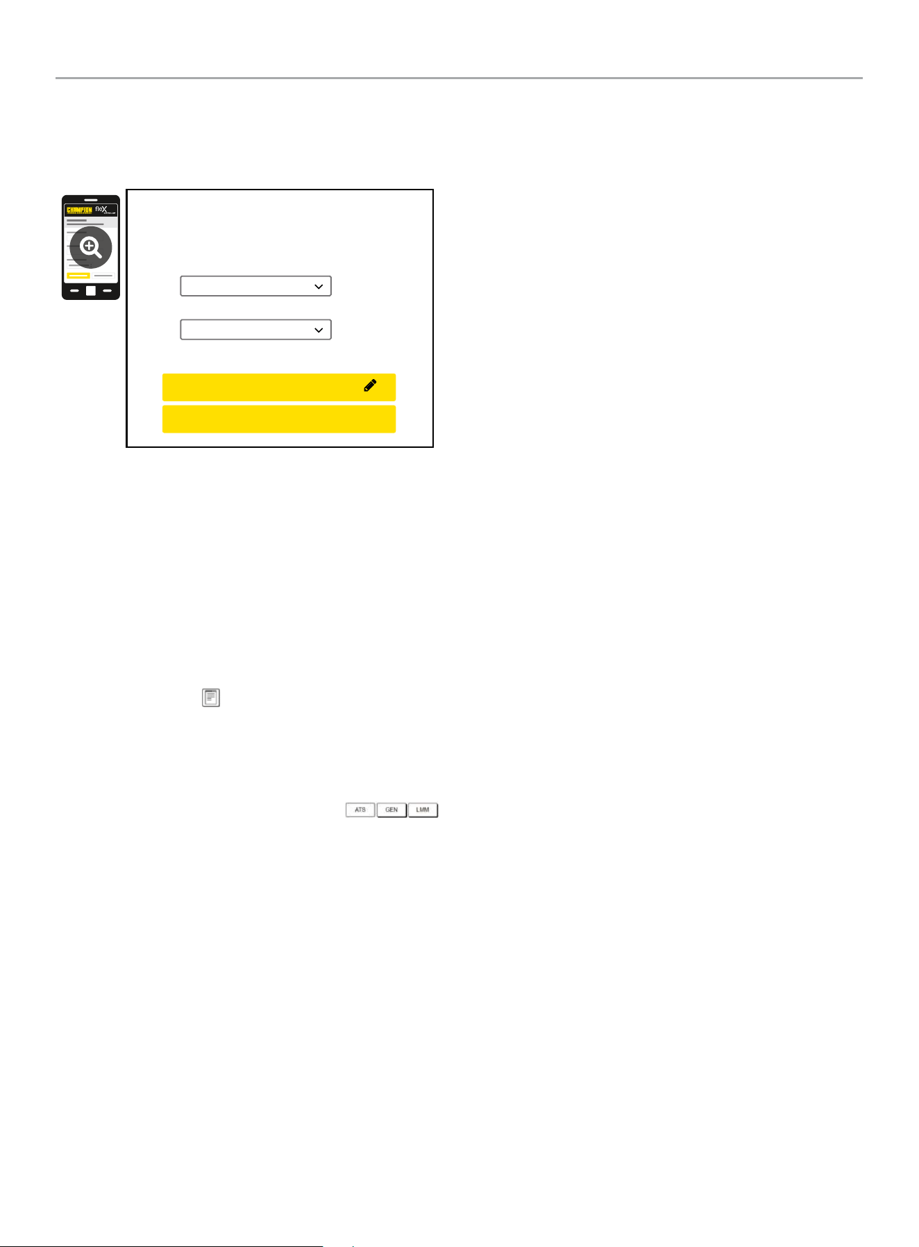
HOME STANDBY GENERATOR- ALL fleX CONTROLLER™ MODELS
CONTROLS AND FEATURES
52
9. Wireless network settings are not used at this time. The
default values (shown below) should not be adjusted.
Adjustment of this factory settings will require a certified
electrician to correct.
Wireless Network
Internet Service:
Web Page Mode:
Direct Connect
AP Mode
CONFIRM NETWORK SETTINGS
CANCEL SETTINGS
AP Mode IP : 192. 168. 0. 90
10. The time, date, and exercise information have now been
setup for the fleX ATS and HSB. You can close your browser
and disconnect from the ATS Wi-Fi, or skip to step 2 in the
next section “ATS and HSB STATUS USING WI-FI”.
ATS and HSB Status Using WIFI
1. Using a WIFI enabled device, connect to the “Champion HSB”
WIFI network following steps 1, 2, and 3 from WIFI Setup
Method.
2. After loading the Home Standby Generator Settings page,
locate and click the icon at the bottom right corner of the
page.
3. You are now viewing the ATS and HSB status page. Items
such as voltage, frequency, current, etc. can all be viewed for
both utility and HSB power. All of the information is live. There
are three tabs located at the top of the page.
ATS, GEN, and LMM. Each tab will display the status for
the Transfer Switch, Home Standby Generator, or Load
Management Module(s) respectively.
4. When finished viewing the status of the ATS, Generator, and
LMM, close your browser and disconnect from the WIFI.
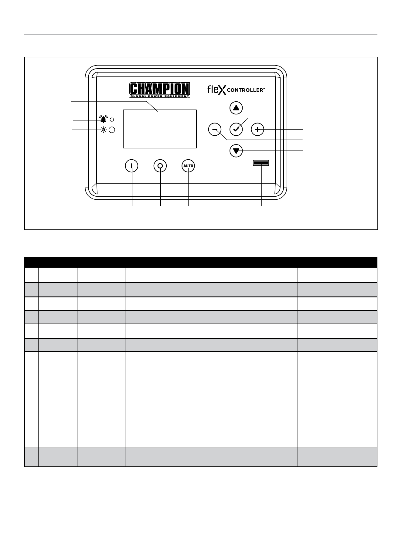
HOME STANDBY GENERATOR- ALL fleX CONTROLLER™ MODELS
PROGRAMMING FLEX CONTROLLER™
53
PROGRAMMING FLEX CONTROLLER
™
Display
Warning
PV
Manual /
ON
OFF Auto
Fuse
Up/Increase
Down/Decrease
Ok
Right
Left
Explanation of USER SETTINGS for setting system and exercise time.
These variables show up after the ATS is connected and powered.
ON SCREEN DESCRIPTION DEFAULT VALUE
1 Year SYS year Year – each digit can be adjusted (example 2023 would be 2023) 2023
2 Month SYS month January to December with 01-12 12
3 Date SYS date Day from 1 to 31 31
4 Hour SYS hour Hours in military time 0 - 23 0
5 Minutes SYS minutes Minutes from 0-59 0
6 Second SYS second Second from 0-59 0
7 Week SYS week
Week day from 1 to 7
1= Monday
2= Tuesday
3= Wednesday
4= Thursday
5= Friday
6= Saturday
7= Sunday
6
8
Daylight
Saving Time
DST DST on “ON” or “OFF” OFF
HOME STANDBY GENERATOR- ALL fleX CONTROLLER™ MODELS
PROGRAMMING FLEX CONTROLLER™
54
ON SCREEN DESCRIPTION DEFAULT VALUE
9
Exercise
Frequency
EXERCISE
FREQ.
Exercise frequency options include:
None = no exercise
1x/MO = 1 time per month (12 times annually)
2x/MO = 2 times per month (24 times annually)
4x/MO = 4 times per month (48 times annually)
1x/WK = weekly (52 times annually)
None
10 Exercise Day EXERCISE DAY
Choose exercise day from 1 to 7
1= Monday
2= Tuesday
3= Wednesday
4= Thursday
5= Friday
6= Saturday
7= Sunday
1
11
Exercise
Start Hour
EXER START H Hours in military time 0 - 23 0
12
Exercise
Start
Minutes
EXER START M Minutes from 0-59 0
13
Exercise
Time
Duration
EXERCISE TIME Exercise duration from 1-100 minutes 15min
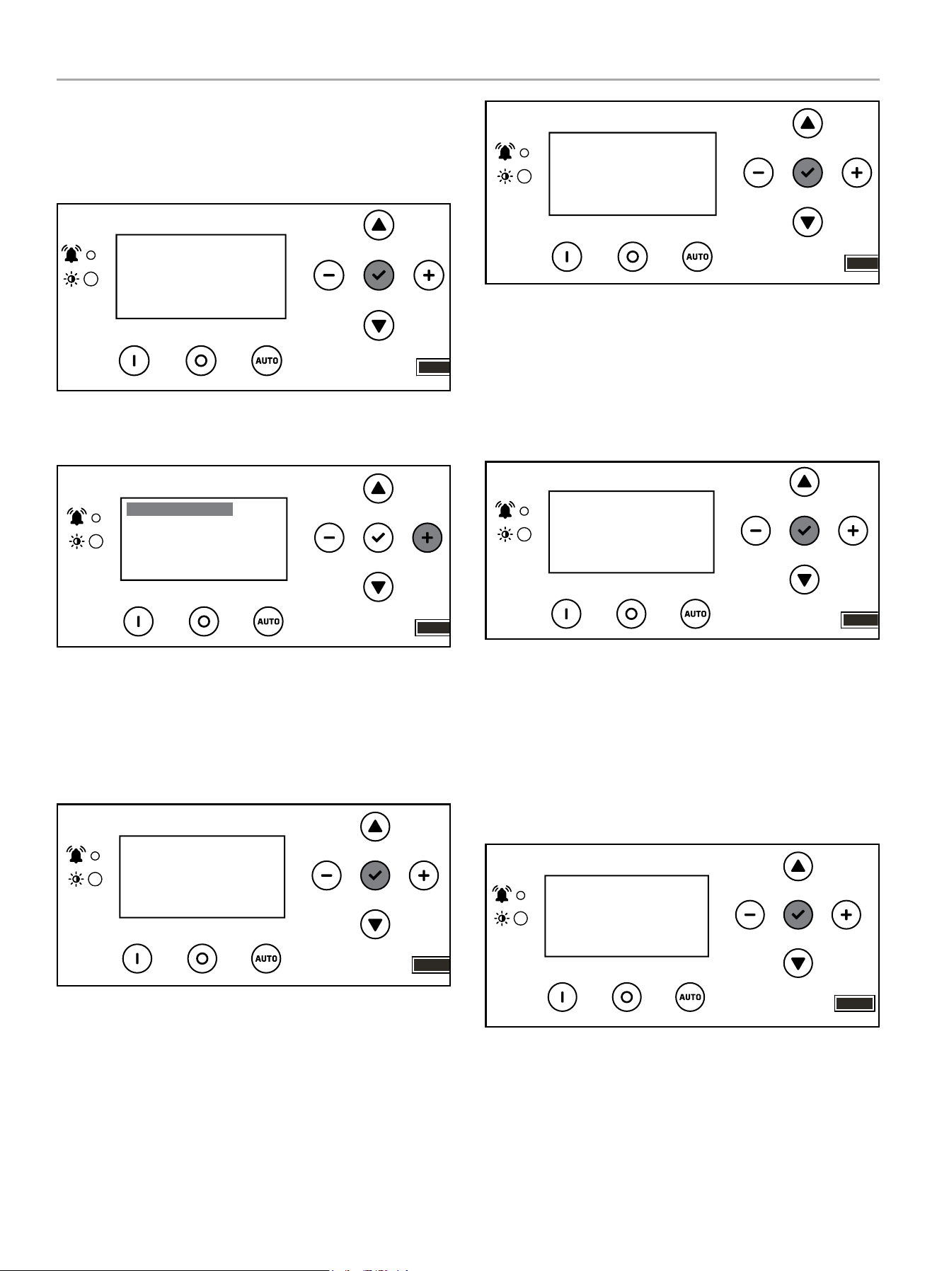
HOME STANDBY GENERATOR- ALL fleX CONTROLLER™ MODELS
PROGRAMMING FLEX CONTROLLER™
55
Setting System Time
1. To begin programming, disable AUTO by pressing OFF. The
screen should show OFF, then press and hold
OK (checkmark icon) for 3 seconds.
OFF
00-00
00:00
ARRÊT
2. Click + until you reach USER SETTINGS. Click down once
until the first menu item is highlighted.
.USER SETTINGS
NEXT SERVICE
RESET SERVICE
BROWNOUT DELAY
100.0h
30s
OFF
3. Scroll down until you reach date settings. Press OK, on the
first setting to adjust year, then month – SYS year and SYS
month. Then use a combination of up/down to adjust each
digit of the year, then - /+ to move to the right or left and
adjust the next digit. Press OK to return and scroll down to
adjust month – SYS month - the same way.
.USER SETTINGS
BRIGHTNESS
BOND MODE
SYS year
100%
2023
OFF
4. Scroll down until you reach date settings. Press OK, on the
next setting to adjust date, hour, and minutes – SYS date,
hour, minutes. Then use a combination of up/down to adjust
each digit on the date, hour, minutes. Then - /+ to move to
the right or left and adjust each digit. Press OK to return and
scroll down to adjust second, week and DST the same way.
.USER SETTINGS
SYS month
SYS date
SYS hour
12
0
31
5. Scroll down until you reach date settings. Press OK, on the
next setting to adjust second, week, and daylight saving time
– SYS second, SYS week, DSI. Then use a combination of up/
down to adjust each digit on the adjust second, week, and
daylight saving time. Then - /+ to move to the right or left and
adjust each digit. DST is just ON or OFF. Press OK to return
and scroll down to adjust exercise information.
.USER SETTINGS
SYS second
SYS week
DST
0
OFF
6
Setting Exercise Time
1. Scroll down until you reach exercise settings. Press OK, on
the next setting to adjust exercise frequency, day and start
time. Then use a combination of up/down to adjust each digit,
then - /+ to move to the right or left and adjust each digit.
Press OK to return and scroll down to adjust hour, minutes
the same way.
EXERCISE FREQ
EXERCISE DAY
EXER START H
None
0
1
.USER SETTINGS
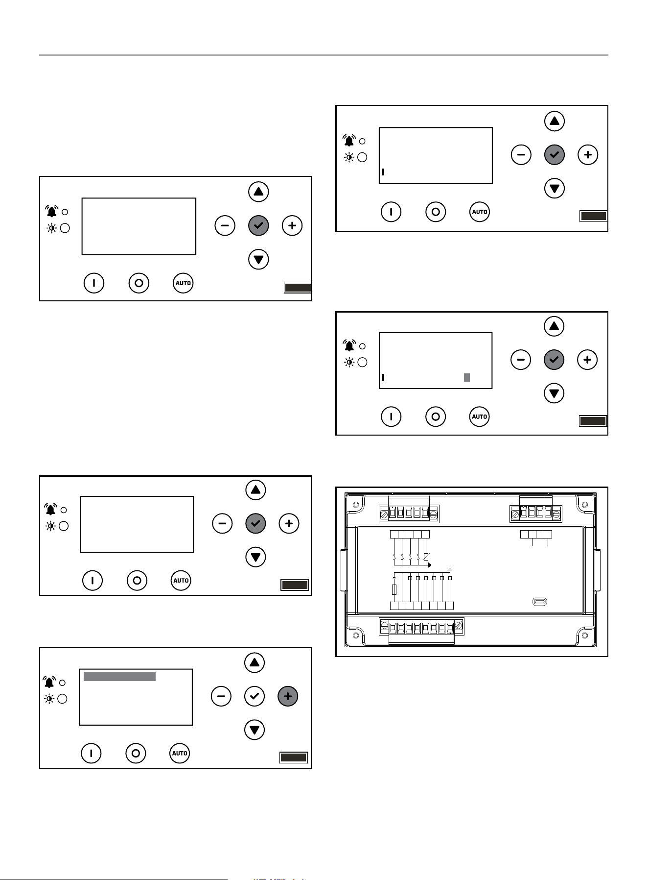
HOME STANDBY GENERATOR- ALL fleX CONTROLLER™ MODELS
PROGRAMMING FLEX CONTROLLER™
56
2. Scroll down until you reach exercise settings. Press OK, on
the next setting to adjust exercise start time (the minutes
portion of the time) and length of exercise (how long the
exercise should run in minutes). Then use a combination of
up/down to adjust each digit on the adjust each digit.
Then - /+ to move to the right or left and adjust each digit.
Press OK to return.
.USER SETTINGS
EXER START M
EXERCISE TIME
0
15min
Setting Brownout Delay
Brownout allows you to adjust the settings of the fleX Controller
™
to delay start up of the HSB during a brownout or partial,
temporary reduction in system voltage or total system capacity
from your utility. Default is 30 seconds. Choose in second
increments (0-600 seconds).
1. To begin programming, disable AUTO by pressing OFF. The
screen should show OFF. Then press and hold OK for 3
seconds.
00-00
00:00
OFF
ARRÊT
2. Click + until you reach USER SETTINGS. Click down once
until the first menu item is highlighted.
.USER SETTINGS
NEXT SERVICE
RESET SERVICE
BROWNOUT DELAY
100.0h
30s
OFF
3. Scroll down until you reach BROWNOUT DELAY, and
press OK.
.USER SETTINGS
NEXT SERVICE
RESET SERVICE
BROWNOUT DELAY
100.0h
30s
OFF
4. Use a combination of up/down to adjust. Then -/+ to move to
right or left each digit brown out delay. Default is 30 seconds.
Choose in second increments (0-600 seconds). Press OK to
return.
.USER SETTINGS
NEXT SERVICE
RESET SERVICE
BROWNOUT DELAY
100.0h
OFF
030
PIN Locations
USB
L2
L1
Reserved
Reserved
ALARM(7A)
IG(7A)
AVR(7A)
GAS(7A)
CRANK(30A)
B-
B+
I-HWT
I-LOP
START
Reserved
9 5
6
78 4
1
23
17 10111213141516
The pins relate to a function of the fleX Controller
™
. These
functions control the operation of the HSB fleX Controller
™
module.
There are 17 pin locations. These are the designated pin locations,
function and wire colors for reference:

HOME STANDBY GENERATOR- ALL fleX CONTROLLER™ MODELS
ATS INSTALLATION
57
Pin Location Function Wire Color
Pin 1 Frequency Over/Under R (Red)
Pin 2 Not Connected
Pin 3 Frequency Over/Under B (Black)
Pin 4 Not Connected
Pin 5 Not Connected
Pin 6 Engine High Temp L (Blue)
Pin 7 Low Oil Pressure Gr (Grey)
Pin 8 Used for two-wire start Br (Brown)
Pin 9 Not Connected
Pin 10 Not Connected
Pin 11 Alarm Br (Brown)
Pin 12 Stop P (Pink)
Pin 13 AVR R/W (Red/White)
Pin 14 Fuel Valve Y (Yellow)
Pin 15 Motor Start Signal Pu (Purple)
Pin 16
B-
B (Black)
Used for two-wire start
Pin 17 B+ R (Red)
Automatic Transfer Switch (ATS)
The most reliable and convenient method to transfer power is with
an automatic transfer switch (ATS). The ATS will automatically
disconnect the home from the utility power prior to the HSB
functioning (see NEC 700, 701 and 702). Failure to disconnect the
home from the utility with an approved UL listed ATS can result
in damage to the HSB and can also cause injury or death to utility
power workers who may receive electrical back-feed from the
HSB.
ATS includes sensors to detect when a power failure (utility lost)
occurs. These sensors trigger the ATS to disengage the home from
the utility power. When the HSB reaches the proper voltage and
frequency, the ATS will automatically transfer generator power to
the home.
The ATS module continues to monitor the utility source for the
return of utility power. When the utility power returns, the ATS
disengages the home from generator power and re-transfers the
home to utility power. The HSB is now off line and will shut down-
returning to the standby mode.
NEMA 3R – This type of enclosed ATS is similar to the indoor box,
except that it is a weatherproof enclosure and required for exterior
installations by code. The enclosure has knockouts on the bottom
and side, and requires water tight connections when installed
outside per code. This enclosure can also be used inside.
fleX Controller
™
Module
This standby generator is designed to communicate with the ATS
using the integrated fleX Controller
™
. In order to utilize features
such as load management, wifi programming, wireless exercise
programming, etc., it is necessary that the ATS contains fleX
Controller
™
electronics.
While it is possible to connect this standby generator to a
non-fleX Controller
™
ATS using the two-wire connection shown
in this manual, it will reduce the functionality of the standby
generator significantly. If the standby generator is being controlled
with the two-wire connection, the standby generator will turn
on and off based on the two-wire signal. Full power will still be
provided through the circuit breaker however will lose functionality
of the ATS (like day, date, time, excercise settings).
ATS INSTALLATION
Refer to the ATS manual enclosed with each ATS for information
related to the installation, operation, service, troubleshooting, and
warranty.
After performing installation of Champion ATS with fleX
Controller
™
, complete the following steps to finish the installation
of this standby generator.
OTE: N If a non-fleX Controller
™
ATS was installed, please skip
to section “Installing Standby Generator to non-fleX
Controller
™
ATS” to finish installation.
Bond Mode
If LMM are installed, please complete the BOND MODE
instructions found in the ATS manual.
Full System Check
1. Please ensure BOND MODE has been completed before final
system check. See ATS manual.
2. Open Utility breaker for full system test, close breaker after
confirming all systems working.
3. After Utility breaker opens engine will start automatically.
4. fleX ATS will reboot on Generator power and control switching
of latching relays.
5. Home is now powered by Generator. If Load Management
modules (LMM) have been installed, please allow 5 minutes
for LMM and AC1/AC2 to become active.
6. Perform Load Learning through ATS panel at this time. LMM
units will be dropped and reacquired in order.
7. Close Utility breaker.
8. System is now fully functional.
9. Put the fleX Controller
™
to the previous position (either
MANUAL or AUTO for example). Confirm utility power is
active, utility side relay is closed, and home is receiving
power.
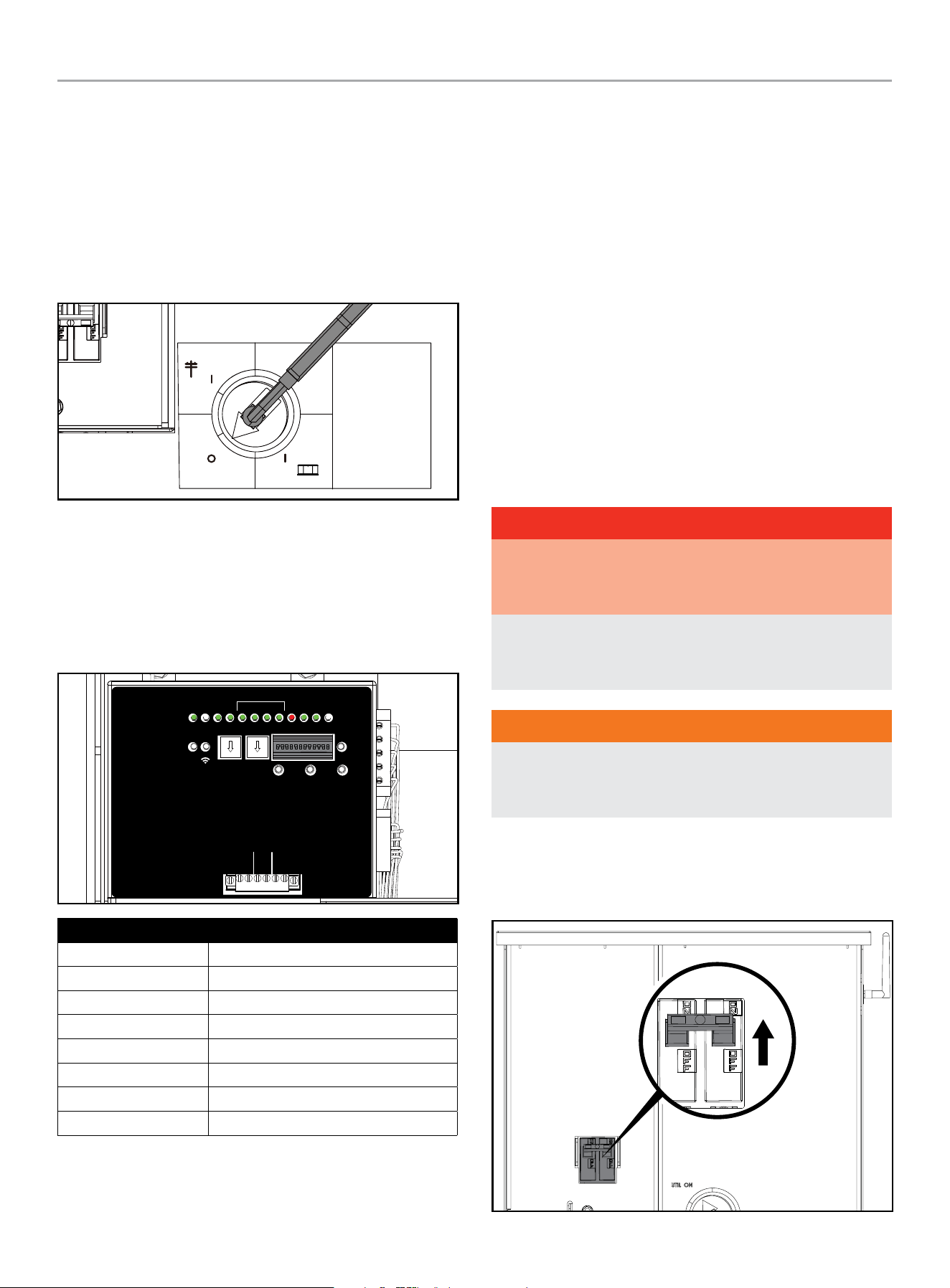
HOME STANDBY GENERATOR- ALL fleX CONTROLLER™ MODELS
ATS INSTALLATION
58
Commissioning the ATS
1. Put the fleX Controller
™
in the OFF position.
2. With door and deadfront removed from the ATS cabinet,
confirm Generator and Utility circuit breakers are in the “OFF”
position.
3. Confirm Manual Operation Switch indicator is in “OFF”
position. If not, place handle on the manual operation switch,
and set the ATS in the OFF position.
Manual
Operation
Switch
Interruptor de
operación manual
Interrupteur de
fonctionnement
manuel
UTILITY
UTILIDAD
UTILITÉ
GENERATOR
GENERADOR
GÉNÉRATRICE
OFF
APAGADO
ARRÊT
4. Re-enable the Utility power to ATS.
5. At ATS panel switch Utility circuit breaker to the “ON”
position. Allow at least 6 minutes for all ATS functions to
resume on controller.
6. Confirm ATS controller in ATS panel has fully booted and
LEDs indicate proper operating condition.
RUN
GSTOP
GS TAR T AC 1 AC2 LM1 LM2 LM3 LM4
ON
1 2 3 4 5 6 7 8 9 10 11 12
GEN UTAL ATSPOS PMT
TEXT
FUNCTION
LEARN
RESET
TEST
PRUEBA
TEST
kW x10 kW x1
DE FAULT
POR DEFECTO
DÉFAUT
LEARN
APRENDER
APPRENDRE
RESET
RESTABLECER
RÉINITIALISER
PMTUTILGENAC1AC2GSTARTGSTOP
RUN
CORRER
MARCHE
WiFi
AC1 AC2
2 WIRE
2 CABLES
2 FILS
ATSPOS
1 2 3 4
LMM
LED Function
GSTOP Green
GSTART Off
AC2 to LM4 Green
GEN Red
UTIL Green
ATSPOS Green
PMT Green
RUN Off
7. Switch Generator circuit breaker to the “ON” position.
8. Replace the dead front by sliding it from the bottom up
into the cabinet; panel should index into the door latch
protrusions. Secure it to the dead front bracket with included
nut and stud.
9. Replace the door and secure with included hardware. It is
recommended to secure the door with a lock.
10. Return to HSB and press the controller to the “AUTO”
position. Confirm icons indicate Utility power is active, Utility
side relay is closed, and home is receiving power.
11. Close and lock HSB cover and return keys to customer.
HSB Test
SPEED SETTING NO LOAD - 22-kW (MODEL 201202)
No speed adjustments are necessary as it’s governed by an
electronic speed controller. ATS door opened, and dead front
removed as well as the HSB hood and various access panels
removed for the following sections.
DANGER
Proceed with caution. Once the Utility Power is turned ON, the
ATS is now electrically hot. The feeder lines and terminals are
now live.
Contact with these connections will result in extremely
hazardous and possibly fatal electrical shock. Use the correct
procedures as described in national electrical codes.
WARNING
The manufacturer recommends that a licensed electrician or
an individual with complete knowledge of electricity perform
these procedures.
1. Place fleX Controller
™
in the OFF position and remove fleX
Controller
™
fuse.
2. Turn ON the utility power supply to the ATS.
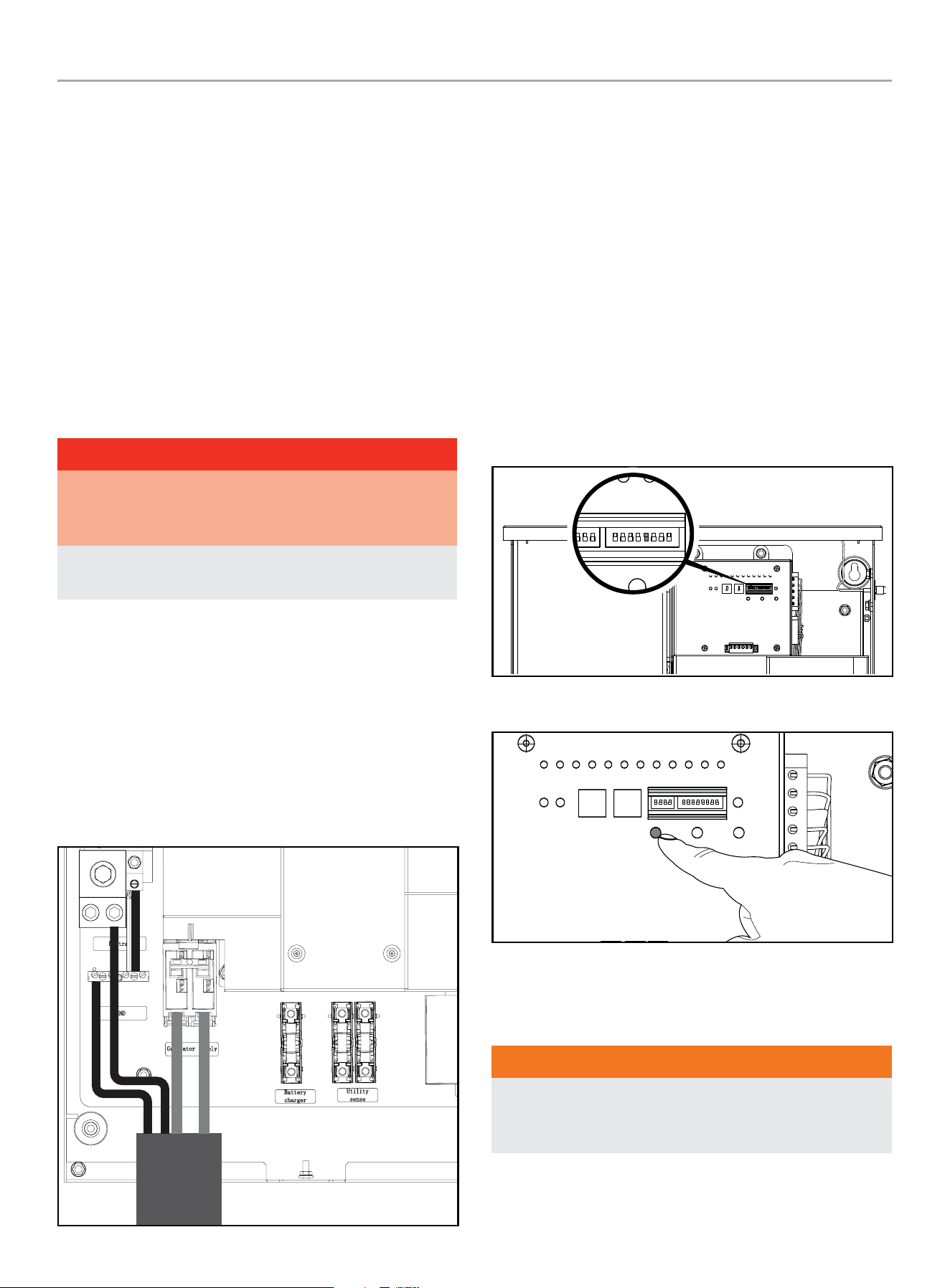
HOME STANDBY GENERATOR- ALL fleX CONTROLLER™ MODELS
ATS INSTALLATION
59
3. With an AC voltmeter, check for the correct voltage. Single-
phase utility power supply. Measure across the UTILITY
SUPPLY ATS terminal lugs L1 and L2. Also check L1 to
NEUTRAL and L2 to NEUTRAL.
4. The utility supply voltage should be correct and compatible
with the ATS ratings.
5. Turn OFF the utility power supply to the ATS.
6. The Control Panel MAIN CIRCUIT BREAKER must be in the
OFF position.
7. Set the fleX Controller
™
in the MANUAL mode. The HSB
will crank and start. Let the HSB warm up at no load for 5
minutes to stabilize performance.
8. Set the Control Panel MAIN CIRCUIT BREAKER in the ON
position.
DANGER
Proceed with caution. HSB generator output voltage is now
being delivered to the ATS and is electrically hot. The feeder
lines and terminals are now live.
Contact with these connections will result in extremely
hazardous and possibly fatal electrical shock.
9. With an AC voltmeter, check the correct voltage. Single-phase
generator supply.
10. Measure across GENERATOR SUPPLY ATS lugs L1 and L2.
Also check L1 to NEUTRAL. These are factory, no load,
pre-set limits.
Frequency
............................................... 62.5 Hertz
Terminals L1 to L2 .........................................240 VAC
Terminals L1 to NEUTRAL .................................120 VAC
Terminals L2 to NEUTRAL .................................120 VAC
11. Set the HSB generator MAIN CIRCUIT BREAKER to its OFF
position.
12. Set the fleX Controller
™
to the OFF position. This will shut off
the HSB.
HSB Tests Under Load
During this test you DO NOT need to turn off any circuit
breakers in the Utility Main Distribution Panel, HSB Control
Panel or the ATS.
This procedure will verify load Voltage and frequency output. Prior
to starting the test, you can place a Manometer in line to check
fuel flow when the HSB is near rated load.
1. Remove ATS dead front.
2. Assure DIP switch #9 (TEST WITH LOAD) is in the ON
position.
RUN
GSTOP
GSTAR T AC1 AC2 LM1 LM2 LM3 LM4
ON
1 2 3 4 5 6 7 8 9 10 11 12
GEN UTAL ATSPOS PMT
WIFI
KW X 10 KW X 1
TEST DEFAULT
FUNCTION
LEARN
RESET
ON
2 3 4 5 6 7 8 9 10 11 12
FUNCTION
ON
3. Press TEST button.
RUN
GSTOP
GS TAR T AC1 AC2 LM1 LM2 LM3 LM4
ON
1 2 3 4 5 6 7 8 9 10 11 12
GEN UTAL ATSPOS PMT
WIFI
KW X 10 KW X 1
TEST DEFAULT
FUNCTION
LEARN
RESET
ON
4. The engine will start and the ATS will transfer.
5. The fleX Controller
™
screen will indicate that the generator is
now suppling power to the home.
WARNING
The manufacturer recommends that a licensed electrician or
an individual with complete knowledge of electricity perform
these procedures.
6. With rated load applied, check voltage and frequency across
ATS GENERATOR SUPPLY terminals L1 and L2. Voltage must
be greater than 216 Volts.

HOME STANDBY GENERATOR- ALL fleX CONTROLLER™ MODELS
ATS INSTALLATION
60
7. Frequency should be greater than 58 Hertz.
8. Verify that the gas pressure remains within the acceptable
parameters as listed in the manual, if you placed a
Manometer in line prior to starting this test.
9. In test mode, the HSB will run under load for 15 minutes at
which time it will conclude the test and shut off automatically.
With the unit running listen for unusual noises, inspect for
vibrations or other unusual items that might reflect a problem.
10. To stop the test prior to automatic shut off, press the Test
Button in the ATS a second time.
11. The HSB will run through a cool down cycle, shut down and
return to standby mode.
12. The test is now complete, and the system is in standby mode.
Checking Automatic Operation
To check the HSB system for proper automatic operation, proceed
as follows:
1. Turn the ATS utility side breaker OFF.
2. Engine will start and the ATS will transfer.
3. Allow the system to go through a complete cycle.
(Approximately 7 minutes)
4. To conclude Automatic Operation Check, turn the ATS utility
breaker ON.
5. The HSB will run through a cool down cycle, shut off, and
return to standby mode.
6. Replace covers on ATS and HSB that were removed for HSB
Test and Checking Automatic Operation. This check is now
complete.
Installing Standby Generator to non-fleX
Controller
™
ATS
OTE: N This section is only for those looking to install their
fleX Controller
™
HSB to a non-fleX Controller
™
ATS that
supports a two-wire HSB start/stop signal. Please refer to
the ATS installation manual for instructions on how to wire
the ATS.
If the fleX Controller
™
HSB is being connected to a
non-fleX Controller
™
ATS, it will be necessary to use a two-wire
connection shown below to control the on/off operation of this
HSB. Note that this will disable some of the fleX Controller
™
features such as load management, WiFi connectivity, and
wireless exercise programming.
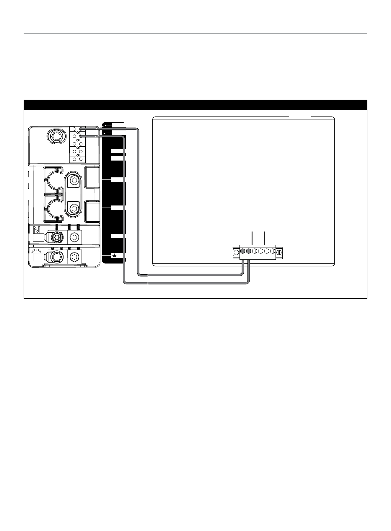
HOME STANDBY GENERATOR- ALL fleX CONTROLLER™ MODELS
ATS INSTALLATION
61
Two-Wire Connection
A two-wire connection refers to a signal circuit that runs between the non-fleX Controller ATS and the HSB. When installed in this
configuration, the HSB will turn on and off based on the signal it is receiving from the ATS. The two-wire signal from the non-fleX
Controller ATS is connected to 2-wire (START) and COM (Ground) Terminal Block 2. Refer to the non-fleX Controller ATS operator’s manual
for the wiring diagram on how to create the circuit.
Champion HSB- Terminal Block 2 Non-fleX Controller ATS
442 6-L-PR -A
N
L1
L2
L
N
2-Wire
COM
AC1 AC2
2 WIRE
2 CABLES
2 FILS

HOME STANDBY GENERATOR- ALL fleX CONTROLLER™ MODELS
MAINTENANCE
62
Customer Familiarization Summary
It’s important to educate the home owner on proper maintenance,
operation and service call procedures. A properly educated home
owner can reduce unnecessary service trips and phone calls.
Ensure that the installation of the HSB and ATS has been correctly
performed as outlined by the manufacturer and that it meets all
applicable codes.
Test and confirm proper operation of the HSB and ATS system as
outlined in the appropriate installation and owner’s manuals.
Educate the home owner on the location and operation of;
– Full flow shutoff valve
– Automatic operation of the HSB system
– Battery Charger and LED indicators
– Exterior warning LED on the backside of the HSB
– ATS operation
– Exercise scheduled time of operation
– Scheduled Maintenance
– Fill out and provide the customer a copy of the HSB,
ATS model & serial number reference. This information
is extremely important for part purchases and service
information, these numbers are specific to each HSB and
ATS.
MAINTENANCE
Before performing maintenance procedures, review SAFETY
section of your operator’s manual.
Ensure that the ATS and generator ON/OFF switches (depending
on model) are in the OFF position before performing any
maintenance or cleaning.
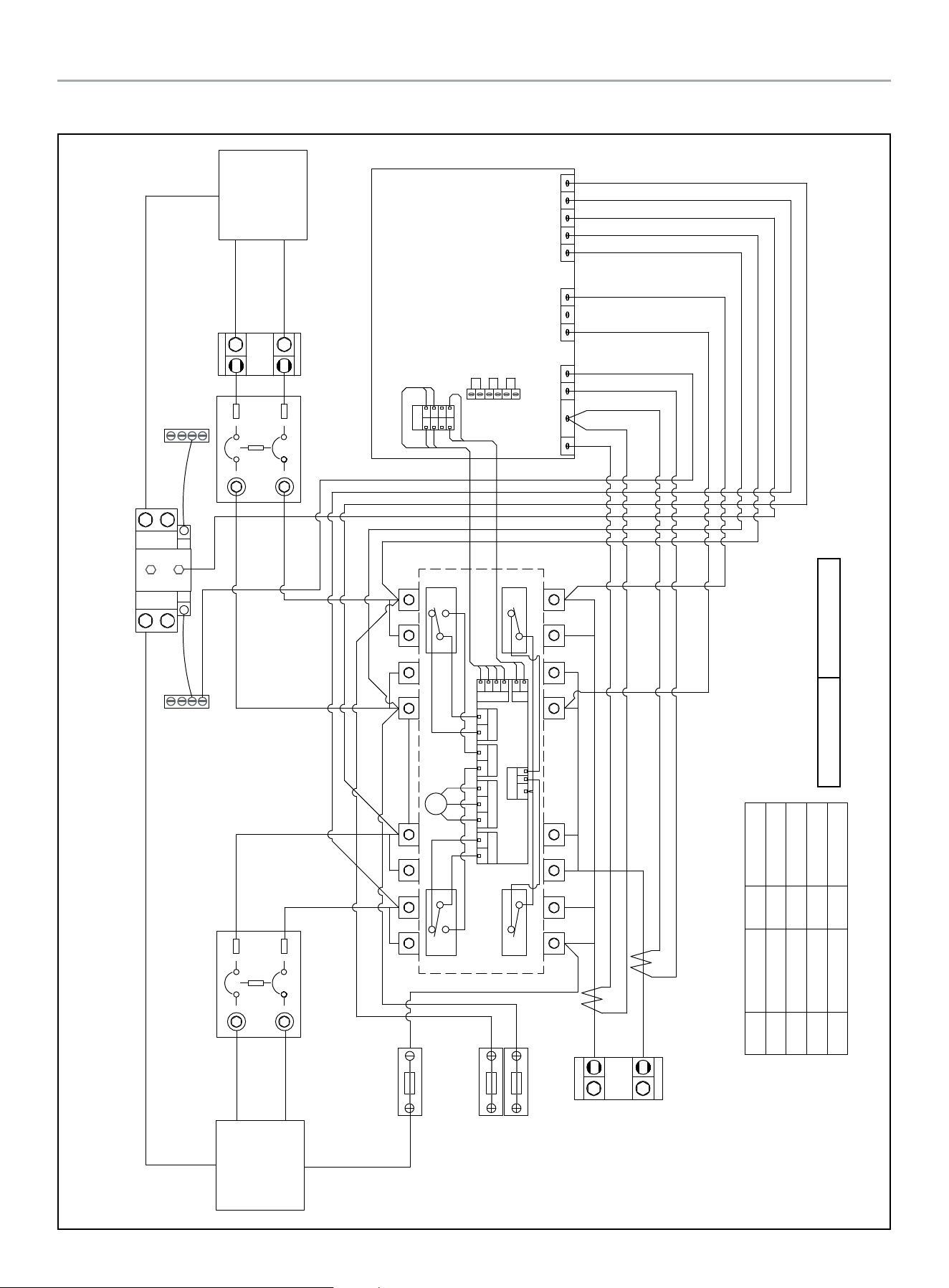
HOME STANDBY GENERATOR- ALL fleX CONTROLLER™ MODELS
201020 ATS WIRING DIAGRAM
63
201020 ATS WIRING DIAGRAM
Charger L
Generator
Supply
Utility
Supply
U-N
U-L1
U-L2
G-N
G-L1
G-L2
Generator Circuit Breaker Utility Circuit Breaker
Ground Bar Ground Bar
Neutral Bar
GN/YE
600Vac KTK-10
Fuse
Battery Charger
BN
600Vac KTK-10
Fuse
RD
BK
Utility Sense
Load
L2
L1
RD/BK RD
RD
BK
WH
RD
GN/YE
CT2-
CT2+
CT1-
CT1+
RD
RD/BK
RD
GN/YE
BU
OG
GND
L1
L2
U-L1
U-L2
N
G-L2
G-L1
RD
BK
WH
GY
YE
fleX Controller
2 Wire
AC1
AC2
RD Red
BK
Black
YE
Yellow
BN
Brown
BU
Blue
WH
White
GY
Grey OG Orange
GN/YE Green/Yellow
GN/YE
Red/Black
RD/BK
RD/BK
CT2+
M
NC_B
NO_B
C_B C_A
NC_A
NO_A
K3
C3 C4
K4
GY
BK
RD
L
VH1
N
G
V
R
J3
T
K4
VH5
C3&C4
K3
NC_A C_A
VH3
NO_B NO_A
VH7
C_B NC_B
VH4
CCW CW
VH2
N
L
G
R T
V
N
H1
RD
BK
BN
OG
GY
RD
YE
GY
GY
BU
BU
BK
BK
RD
YE
GY
BKRD
BK
GY
RD
YE
CT1- & CT2-
CT1+
GND
U-L1
U-L2
N
G-L2
G-L1
RD/BK
L1
L2
Open Transition Break Before Make
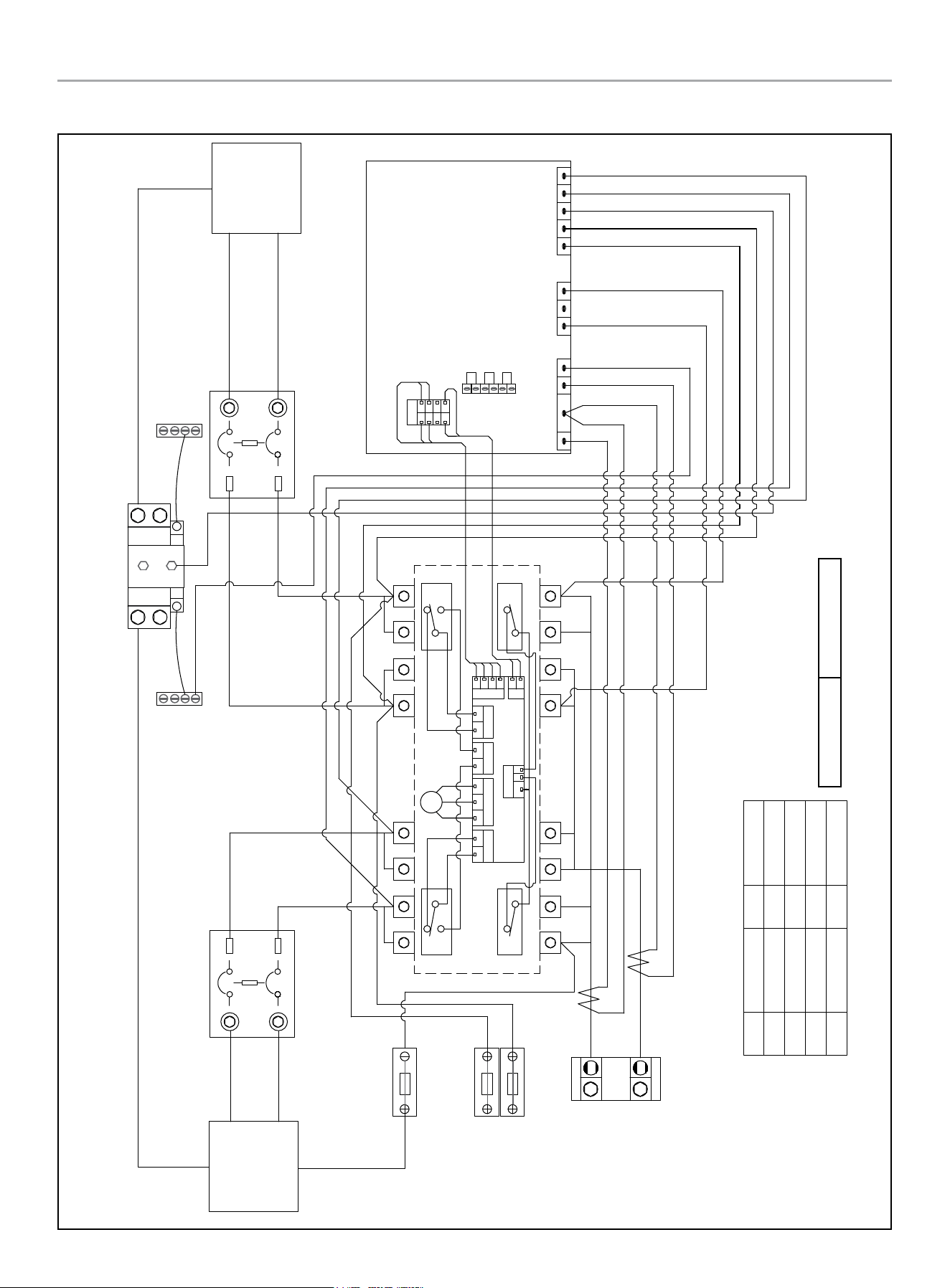
HOME STANDBY GENERATOR- ALL fleX CONTROLLER™ MODELS
201039 ATS WIRING DIAGRAM
64
201039 ATS WIRING DIAGRAM
Charger L
Generator
Supply
Utility
Supply
U-N
U-L1
U-L2
G-N
G-L1
G-L2
Generator Circuit Breaker Utility Circuit Breaker
Ground Bar Ground Bar
Neutral Bar
GN/YE
600Vac KTK-10
Fuse
Battery Charger
BN
600Vac KTK-10
Fuse
RD
BK
Utility Sense
Load
L2
L1
RD/BK RD
RD RD/BK
WH
GN/YE
CT2-
CT2+
CT1-
CT1+
GND
L1
L2
U-L1
U-L2
N
G-L2
G-L1
fleX Controller
RD Red
BK
Black
YE
Yellow
BN
Brown
BU
Blue
WH
White
GY
Grey OG Orange
GN/YE Green/Yellow
GN/YE
Red/Black
RD/BK
M
NC_B
NO_B
C_B C_A
NC_A
NO_A
K3
C3 C4
K4
GY
BK
RD
L
VH1
N
G
V
R
J3
T
K4
VH5
C3&C4
K3
NC_A C_A
VH3
NO_B NO_A
VH7
C_B NC_B
VH4
CCW CW
VH2
N
L
G
R T
V
N
H1
RD
BK
BN
OG
GY
RD
YE
GY
GY
BU
BU
BK
BK
RD
YE
GY
BKRD
BK
GY
RD
YE
RD
RD/BK
RD
GN/YE
BU
OG
RD
BK
WH
GY
YE
2 Wire
AC1
AC2
CT2+
CT1- & CT2-
CT1+
GND
U-L1
U-L2
N
G-L2
G-L1
RD/BK
L1
L2
Open Transition Break Before Make
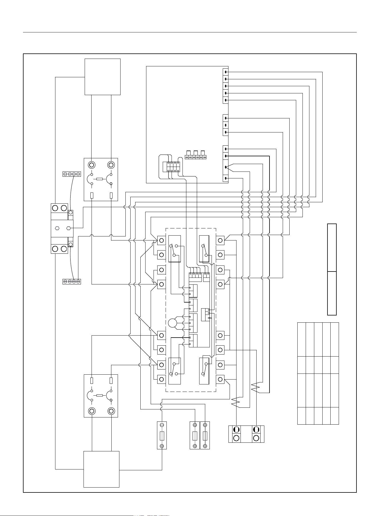
HOME STANDBY GENERATOR- ALL fleX CONTROLLER™ MODELS
201355 ATS WIRING DIAGRAM
65
201355 ATS WIRING DIAGRAM
Charger L
Generator
Supply
Utility
Supply
U-N
U-L1
U-L2
G-N
G-L1
G-L2
Generator Circuit Breaker Utility Circuit Breaker
Ground Bar Ground Bar
Neutral Bar
GN/YE
600Vac KTK-10
Fuse
Battery Charger
BN
600Vac KTK-10
Fuse
RD
BK
Utility Sense
Load
L2
L1
RD/BK RD
RD RD/BK
WH
GN/YE
CT2-
CT2+
CT1-
CT1+
GND
L1
L2
U-L1
U-L2
N
G-L2
G-L1
fleX Controller
RD Red
BK
Black
YE
Yellow
BN
Brown
BU
Blue
WH
White
GY
Grey OG Orange
GN/YE Green/Yellow
GN/YE
Red/Black
RD/BK
M
NC_B
NO_B
C_B C_A
NC_A
NO_A
K3
C3 C4
K4
GY
BK
RD
L
VH1
N
G
V
R
J3
T
K4
VH5
C3&C4
K3
NC_A C_A
VH3
NO_B NO_A
VH7
C_B NC_B
VH4
CCW CW
VH2
N
L
G
R T
V
N
H1
RD
BK
BN
OG
GY
RD
YE
GY
GY
BU
BU
BK
BK
RD
YE
GY
BKRD
BK
GY
RD
YE
RD
RD/BK
RD
GN/YE
BU
OG
RD
BK
WH
GY
YE
2 Wire
AC1
AC2
CT2+
CT1- & CT2-
CT1+
GND
U-L1
U-L2
N
G-L2
G-L1
RD/BK
L1
L2
Open Transition Break Before Make
HOME STANDBY GENERATOR- ALL fleX CONTROLLER™ MODELS
TROUBLESHOOTING HSB
66
TROUBLESHOOTING HSB
Engine will not crank/turn over
1 HSB set in “OFF” mode. Place the fleX Controller in the AUTO position.
2 Battery not connected or loose, corroded posts or wires
Connect the batteries according to owner’s manual, clean and tighten
the battery connections
3 Battery(s) not charged or low charge. Recharge or replace battery(s).
4 Check for active fault code. Identify fault code, correct and reset.
5 Defective starter solenoid *
6 Defective starter *
7 Generator ON/OFF switch is in the OFF position. Check the generator ON/OFF switches are in the ON position.
Generator will crank/turn over but will not start
1 Check for active fault code. Identify fault code, correct and reset.
2 Fuel valve(s) turned off. Turn on fuel supply.
3 Fuel pressure insufficient*. Manometer check, confirm fuel pressure to fuel regulator*.
4 Weak battery(s). Recharge or replace battery(s)
5 Low oil level. Check for oil leaks. Check the oil level and add oil if necessary.
6 Spark plug wire is disconnected. Connect spark plug wire.
7 Defective fuel solenoid/regulator. *
Engine starts, runs rough
1 Fuel pressure insufficient*. Manometer check, confirm fuel pressure to fuel regulator*.
2 Wrong fuel. Check Fuel Selector Dial is in the correct position.
3 Faulty spark plug, loose spark plug wire. Change spark plug, set gap, connect wire.
4 Plugged air cleaner Clean or replace air cleaner.
5 Generator overloaded*. Remove one or more loads*.
6 Shorted circuit *
HSB starts, then suddenly stops
1 Check for active fault code. Identify fault code, correct and reset.
2 Fuel supply insufficient* Manometer check, confirm fuel pressure to fuel regulator*.
3 Low oil, pressure shut down Check for oil leaks. Check the oil level and add oil if necessary.
4 Generator over loaded
Turn off standby circuits for house, reset fault, place unit back into
AUTO and ATS mode. Turn on standby circuits for house. If problem
returns contact Champion or Champion service dealer*.
5 Engine high/over temperature shut down
Check all intake and exhaust ventilation around the HSB, remove all
debris. Let HSB sit for 30 minutes to cool down.

HOME STANDBY GENERATOR- ALL fleX CONTROLLER™ MODELS
TROUBLESHOOTING HSB
67
No AC output
1 Circuit breaker in “OFF” position Turn on breaker.
2 Main circuit breaker in “OFF” position. Turn on breaker.
3 Transfer switch breaker in “OFF” position. Turn on breaker.
4 Generator or HSB breaker is set in “OFF” position. Turn on breaker.
5 Line circuit tripping breaker because of short circuit *
6 Line circuit tripping breaker because of overload *
7 Poor wiring connections*
8 ATS problems*
Reset fault code(s)
There is an exterior warning LED located on the back of the enclosure. This should be checked weekly to make sure there are no active
fault codes.
The fault code(s) can be reset by placing the fleX Controller
™
in the OFF position for 10 seconds and then placed into ATS mode. This will
reset fault icon, however if a fault code(s) re-occurs it must be addressed.
BATTERY(S) NO OR LOW LEVEL CHARGED, BATTERY(S) DEAD, NEEDS REPLACEMENT, THE EXERCISE TIME MUST BE RESET ONCE
THE BATTERY(S) HAVE BEEN DISCONNECTED.
* Contact Champion Power Equipment, Technical Service toll free 1-877-338-0999, tech@championpowerequipment.com or your nearest Champion dealer.
www.championpowerequipment.com

HOME STANDBY GENERATOR- ALL fleX CONTROLLER™ MODELS
TROUBLESHOOTING HSB
68
HSB, ATS Model & Serial Reference ATS Back-up Circuits
HSB Model Number
HSB Serial Number
Fuel Type LPG NG
ATS Model Number
ATS Serial Number
ATS circuits powered
Date Installed
Dealer/Installer
Address
Phone
Cell
Purchased from