
DANGER: Not intended for use in critical life support application.
DANGER: Generator must be installed and operated outdoors only.
REV 20250311

Have questions or need assistance?
DO NOT return this product to the store!
WE ARE HERE TO HELP!
Visit our website:
www.championpowerequipment.com
for more info:
• Product Info & Updates
• Frequently Asked Questions
• Tech Bulletins
• Product Registration
– or –
Call our Customer Care Team Toll-Free at:
1-877-338-0999
*We are always working to improve our products. Therefore, the enclosed product may differ slightly from the image on the cover.
CALIFORNIA PROPOSITION 65 WARNING
Cancer and Reproductive Harm – www.P65Warnings.ca.gov
DISCLAIMERS
All information, illustrations and specifications in this manual are based on the latest information available at the time
of publishing. The illustrations used in this manual are intended as representative reference views only. Products
are under a continuous improvement policy. Thus, information, illustrations and/or specifications to explain and/or
exemplify a product, service or maintenance improvement may be changed at any time without notice.
ALL RIGHTS RESERVED
No part of this publication may be reproduced or used in any form by any means – graphic, electronic or
mechanical, including photocopying, recording, taping or information storage and retrieval systems – without the
written permission of Champion Power Equipment (CPE).

3
CONTENTS
Part No. 101049
CONTENTS
Home Standby Generator ................................................5
Parts Included .................................................................5
INTRODUCTION ....................................................6
HSB Models .....................................................................6
Standard Features, Tailor-Made Solutions .....................6
General Information,
Standards and Codes ......................................................7
SAFETY ................................................................8
Safety Symbol Definitions ............................................... 8
Warnings .................................................................8
Mandatory Actions ...................................................9
Installation Hazards ........................................................9
Before Starting ..............................................................10
Operating Hazards .........................................................10
Accidental Starting .......................................................11
Carbon Monoxide Hazards ............................................11
Electrical Shock Hazards ..............................................12
Fire/Explosion Hazards .................................................12
Burn Hazards ................................................................. 12
Entanglement Hazards ..................................................13
Battery Hazards .............................................................13
Safety Labels .................................................................13
Safety Labels On Unit .............................................14
Safety, Serial/Model, Nameplate Label Locations .... 15
8.5 KW SPECIFICATIONS - MODEL 100199 ....................16
Champion 439cc Engine ................................................17
Champion 439cc Engine Torque Specifications ...........17
Master Mixing Assembly Jets (Carburetor System) ....17
11-12.5 kW Specifications ............................................18
Champion 717cc Engine ................................................19
Champion 717cc Engine Torque Specifications ...........19
Master Mixing Assembly Jets (Carburetor System) ....19
14 KW SPECIFICATIONS - MODEL 100237 .....................20
Champion 754cc Engine ................................................21
Champion 754cc Engine Torque Specifications ...........21
Master Mixing Assembly Jets (Carburetor System) ....21
Alternator Overview ......................................................22
Rotor Assembly ...................................................... 22
Stator Assembly ..................................................... 22
Brush Holder And Brushes .....................................22
UNPACKING ........................................................23
INSTALLATION ...................................................24
Generator Sizing ............................................................ 24
Placement & Installation Guidelines for Champion Home
Standby Generators to Reduce the Risk of Fire ...........25
National Fire Protection Association (NFPA) Standard
NFPA 37
Requirements And Testing ............................................25
Intertek Group PLC Label ..............................................26
Site Selection, Preparation and Placement ..................27
Suggested Site Selection .......................................27
Suggested Preparation ........................................... 28
Suggested Placement ............................................28
Installation Preparation ................................................29
1. Fuel Requirements and
Recommendations ....................................................... 30
2. Fuel Consumption ..............................................31
3. NG Pipe Sizing ...................................................31
4. LPG Vapor Pipe Sizing ........................................32
5. Converting to LPG ..............................................33
6. Full Fuel Shut Off ...............................................36
7. Sediment Trap ....................................................36
8. Checking Pressure with a Manometer ................36
9. Battery Requirements,
Installation & Service ...................................................37
Wire Sizing ....................................................................39
Installing Communication Wires .............................40

4
CONTENTS
Part No. 101049
Identify/Select Standby
Circuits ..........................................................................40
Surge protection ............................................................41
Hour Meter & Over Voltage Protection ..........................41
Hour Meter ............................................................41
Over Voltage Protection (OVP) ................................ 41
Exercise LED .................................................................. 41
Set Exercise Time ..........................................................41
AVR = Automatic Voltage Regulator ............................42
Engine Relay Module ..................................................... 43
Top Row ................................................................43
Bottom Row ........................................................... 44
Engine Controller ........................................................... 44
Mode Switch ..........................................................44
Pin Locations .........................................................47
Exterior Warning LED ....................................................49
ATS Control Module ....................................................... 49
Test/Auto/Off Switch ..............................................49
Pin Locations .........................................................50
ATS Select Switch
(does not apply to model 100199.) ....................................50
Battery Charger .............................................................50
HSB Test ........................................................................51
Voltage Checks – No Load......................................51
Twin Cylinder Frequency Adjustment ...........................53
HSB Tests Under Load ............................................ 53
Checking Automatic Operation .....................................54
Customer Familiarization Summary .............................54
Automatic Transfer Switch (ATS) .................................. 55
Unpacking .............................................................55
Location And Mounting ..........................................55
Circuit Breakers For Utility Main Control
Panel and ATS ..............................................................56
Electrical Grommet(S) ............................................56
Installation Wiring For Ats To Utility Main
Control Panel ...............................................................56
Installing Communication Wires .............................57
Power / Conductor Wire Sizing ...............................58
Commissioning The ATS ......................................... 58
ATS Circuit Board Fuse Information .............................59
ATS Fuse Troubleshooting and Testing ......................... 59
Fuses F2 and F3 ....................................................59
Fuses F4 and F5 ....................................................59
Fuse F1 .................................................................59
Fuse F6 .................................................................60
Manual Transfer Switch ................................................60
Troubleshooting HSB .....................................................61
HSB and ATS Model & Serial Reference, ATS Back-Up
Circuits ..........................................................................63

5
CONTENTS
Part No. 101049
Congratulations on your purchase of a Champion Power
Equipment (CPE) home standby generator. This generator is
designed and engineered in the USA to exacting standards of the
North American market. This engine-powered generator meets
all Environmental Protection Agency (EPA) Phase 3 requirements
and is approved by CETLUS as tested to UL2200 and CSA22.2
No. 100 in both the USA and Canada.
With proper use and maintenance, this generator will provide
years of satisfying service.
The Champion Staff,
Champion Power Equipment
6370 S Pioneer Way, Unit 101
Las Vegas, NV 89113
Toll-free: 1-877-338-0999
Mon-Fri 8:30 AM – 5:00 PM (PST/PDT)
www.championpowerequipment.com
HOME STANDBY GENERATOR
This home standby generator is intended exclusively for outdoor
installation. This generator will operate using either liquefied
petroleum gas (LPG, Propane) or natural gas (NG).
This generator is designed to supply typical home load such as:
• Induction motors – sump pumps, refrigerators, air
conditioners, furnaces
• Electronic items – televisions, computers
• Household lighting
• Microwaves
• This generator is not intended for use in critical life support
applications.
Proper sizing of the generator is required to ensure proper
operation of appliances. Some appliances require additional
wattage to start and must be considered.
PARTS INCLUDED
Your HSB ships with the following:
• Operators Manual
• Installation Manual
• Oil Drain Pan
• Flexible Fuel Line
• HSB Enclosure Keys
• Battery Cable Connection
• LPG Low-speed and Main Converting Jets
• Jet Change Tool
• Lock Nut M6
• Washer, Ø6
• Flange bolt, M6 × 15
6
Part No. 101049
INTRODUCTION
HSB MODELS
Wattage Model Number Description Section
8.5kW
100199 HSB Generator Only
Page 16-17
100947 ATS Only 50A NEMA 1 (non-pre-wired switch)
100950 ATS Only 50A NEMA 3R (non-pre-wired switch)
100174 HSB & 50A ATS NEMA 1 (non-pre-wired switch)
100177 HSB & 50A ATS NEMA 3R (non-pre-wired switch)
11kW
100152 HSB Generator Only
Page 18-19100175 HSB & 99A ATS NEMA 1 (non-pre-wired switch)
100171 HSB & 99A ATS NEMA 3R (non-pre-wired switch)
12.5kW
100136 HSB Generator Only
Page 18-19100176 HSB & 99A ATS NEMA 1 (non-pre-wired switch)
100179 HSB & 99A ATS NEMA 3R (non-pre-wired switch)
14kW
100237 HSB Generator Only
Page 20-21100295 HSB & 100A ATS NEMA 1 (non-pre-wired switch)
100292 14kW HSB & 100A ATS NEMA 3R (non-pre-wired switch)
STANDARD FEATURES, TAILOR-MADE SOLUTIONS
: Tested and approved by CARB, EPA and UL in both USA and Canada
: HSB Designed and Engineered in the USA by Champion
: Milwaukee Series Engine, Designed and Engineered in USA by Champion
: 10 year, 2000 hour limited warranty
: Easy access, all weather steel, sound attenuated enclosure, Gull Wing door design, quite operation
: Composite Mounting Pad, eliminates the need of concrete pad unless required by code
: Natural Gas (NG) or LP gas (propane) operation
: Exterior LED fault light (turns on if unit controller detects a fault code)
: Automatic weekly exercise, operates engine and generator between outage events, system check
: On board battery charging and monitoring, digital LED controller
: Engine and Generator monitoring, digital LED controller
: Fast/Tran ATS (automatic transfer switch), safe and simple, extremely high speed switching system
: Flexible fuel line connector, absorbs vibration when connected to rigid piping
Champion Power Equipment is a market leader in power generation equipment. Champion has years of experience designing and
manufacturing dependable and durable power products designed and engineered in the US to the exacting standards of the North
American market. All our residential standby products are designed in conformance with Environmental Protection Agency (EPA)
requirements, California Air Resource Board (CARB) regulations and are approved by Underwriters Laboratory (UL) in both the USA and
Canada. When the power goes out you’ll want a Champion by your side.

7
INTRODUCTION
Part No. 101049
GENERAL INFORMATION,
STANDARDS AND CODES
The following information related to General Information and
Standards was gathered from the list of publications related
to installing the HSB generator. A multitude of other materials
related to generators were also used concerning common
practice, knowledgeable installation practices, certified
electrical experience and work related experiences. This
information is not all inclusive and the manufacturer strongly
recommends the owner and installer become familiar with all
pertinent codes, standards and regulations. Always check for
the latest publications date to ensure you are current. Have
only a qualified/certified electrician or installation technician
who is knowledgeable about applicable codes, standards and
regulations install and service the generator.
NFPA NO. 30, FLAMMABLE AND COMBUSTIBLE LIQUID
CODE
National Fire Protection Association
470 Atlantic Avenue, Boston, MA. 02210
NFPA NO. 37, STATIONARY COMBUSTION ENGINES AND
GAS TURBINES
National Fire Protection Association
470 Atlantic Avenue, Boston, Ma. 02210
NFPA NO. 76A, ESSENTIAL ELECTRICAL SYSTEMS FOR
HEALTH CARE FACILITIES
National Fire Protection Association
470 Atlantic Avenue, Boston, Ma. 02210
NFPA NO. 54, NATIONAL FUEL GAS CODE
National Fire Protection Association
470 Atlantic Avenue, Boston, Ma. 02210
NFPA NO. 58, AMERICAN NATIONAL STANDARD FOR
STORAGE AND HANDLING OF LIQUID PETROLEUM GAS
National Fire Protection Association
470 Atlantic Avenue, Boston, Ma. 02210
NFPA NO. 70, NFPA HANDBOOK OF ELECTRIC CODE
National Fire Protection Association
470 Atlantic Avenue, Boston, Ma. 02210
ARTICLE X, NATIONAL BUILDING CODE
American Insurance Association
85 John Street, New York, N.Y. 10038
AGRICULTURAL WIRING HANDBOOK
Food and Energy Council
909 University Avenue, Columbia, Mo. 65201
ASAE EP-3634, INSTALLATION AND MAINTENANCE OF
FARM STANDBY ELECTRICAL SYSTEMS
American Society of Agricultural Engineers
2950 Niles Road, St. Joseph, Mi. 49085
8
Part No. 101049
SAFETY
!
This is the safety alert symbol. It is used to alert
you to potential physical injury hazards. Obey all
safety messages that follow this symbol to avoid
possible injury or death.
The words DANGER, WARNING, CAUTION and NOTICE are used
throughout this manual to highlight important information.
!
DANGER
Indicates a hazardous situation that, if not avoided, will
result in death or serious injury.
!
WARNING
Indicates a hazardous situation that, if not avoided,
could result in death or serious injury.
!
CAUTION
Indicates a hazardous situation that, if not avoided,
could result in minor or moderate injury.
NOTICE
Indicates a situation that can cause damage to the
equipment, personal property and/or the environment, or
cause the equipment to operate improperly.
OTE: N Indicates a procedure, practice or condition that
should be followed in order for the generator to
function in the manner intended.
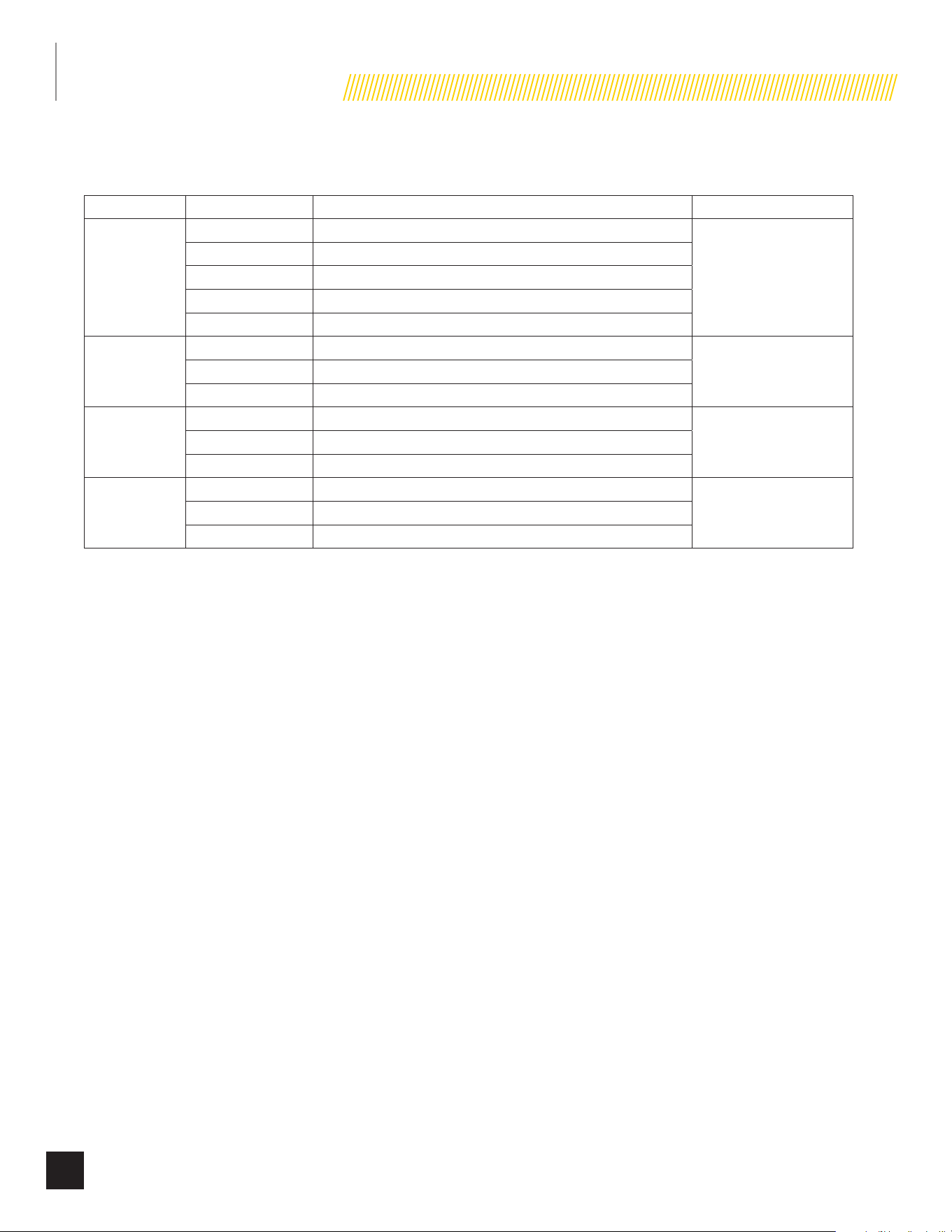
SAFETY SYMBOL DEFINITIONS
Black hazard pictorial on yellow
equilateral triangle enclosed by black
triangular band
Warns that hazard exists and describes
its nature and/or consequences
Black hazard pictorial on white circle
enclosed by red circular band with red
diagonal bar
Depicts action NOT to be taken or
action to be stopped in order to avoid
hazard
White hazard pictorial on blue circle
Depicts action to be taken in order to
avoid hazard
WARNINGS
!
Safety alert symbol
Asphyxiation hazard
Electrical shock hazard
Entanglement hazard
Fire hazard
9
SAFETY
Part No. 101049
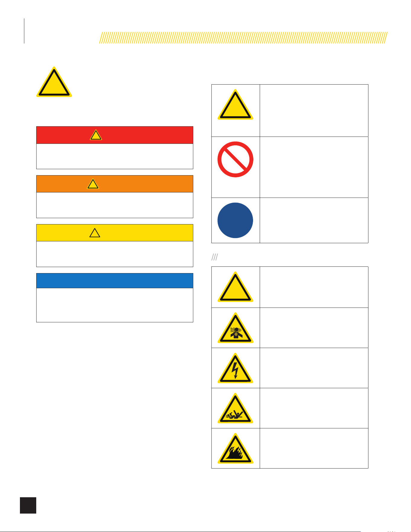
Explosion hazard
Burn hazard
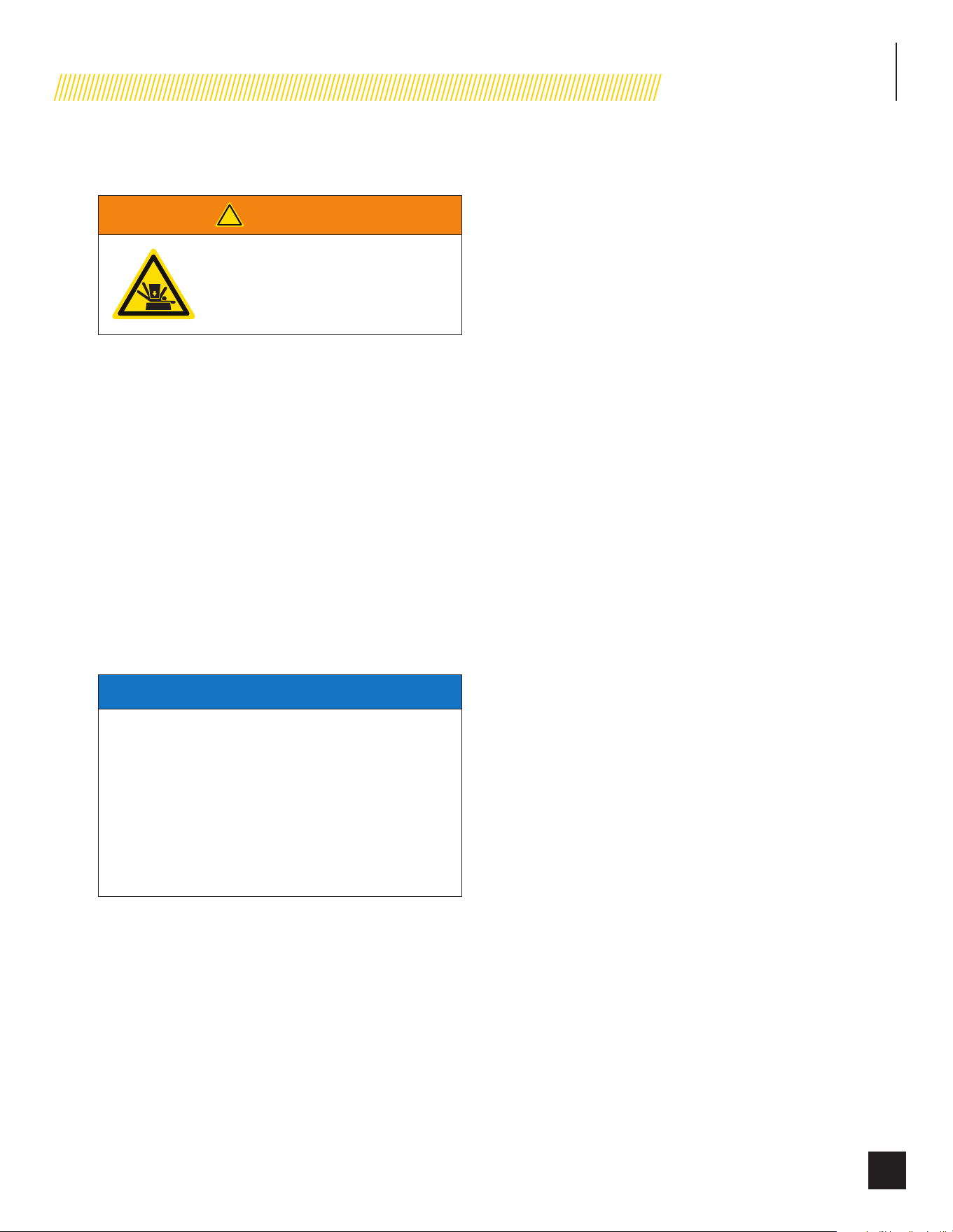
Sever hazard (rotating blade)
Crush hazard (top)
MANDATORY ACTIONS
Read manufacturer’s instructions
Wear eye protection
Wear personal protective equipment
Do not leave tools in the area
INSTALLATION HAZARDS
!
WARNING
!
Have only a qualified electrician
or installation technician who is
familiar with applicable codes,
standards and regulations install
and service the generator.
ALWAYS comply with local, state and national electrical
and building codes when installing the generator.
NEVER alter the recommended installation in a way
that would render the unit noncompliant with these
codes.
ALWAYS comply with regulations that Occupational
Safety and Health Administration (OSHA) has
established.
ENSURE the generator is installed following the
manufacturer’s instructions.
NOTICE
Before welding components on the generator, contact CPE
for recommended welding instructions.
!
WARNING
!
Not intended for use in critical life
support applications.
10
SAFETY
Part No. 101049
BEFORE STARTING
!
CAUTION
Before starting, operating and
maintaining this generator, be sure
to read and understand the content
and safety messages in this manual.
The operator is responsible for safe operation and
maintenance of the generator. Be sure all potential
users of the generator also understand these
instructions. If any portion of this manual is not
understood, contact your dealer for assistance before
operating the generator.
The operator is responsible for performing all safety
checks, making sure all maintenance is properly
performed and making sure the generator is
periodically checked by the dealer.
Inspect the generator regularly. Contact your dealer if
repairs are needed.
NEVER climb or step on any part or components of
the generator. Doing so may result in injury and cause
leaking fuel and exhaust.
OPERATING HAZARDS
!
WARNING
!
ALWAYS operate the generator
following the manufacturer’s
instructions. Operating the generator
imprudently, neglecting maintenance
or being careless can result in injury
or possible death.
DO NOT allow children or unqualified persons to
operate or service the generator.
NEVER operate the generator with the covers open.
Operate the generator only with the covers closed and
secured in place. NEVER leave the covers unlocked.
Remain alert at all times when working on the
generator. NEVER work on the generator when
physically or mentally fatigued.
Never operate the generator while under the influence
of alcohol or drugs. Their effects on vision and
judgment make operating a generator dangerous.
11
SAFETY
Part No. 101049
ACCIDENTAL STARTING
!
WARNING
ALWAYS prevent the generator from starting while the
covers are open. The generator may crank and start at
any time without notice. Follow these steps in order:
1. Turn the exercise switch to the OFF position.
2. Switch the main circuit breaker to the OFF
position.
3. Turn the ATS control module to the OFF position.
4. Turn the engine control module switch to the
OFF position.
5. Disconnect the NEGATIVE, NEG or (-) battery
cable first, and then remove the POSITIVE, POS
or (+) battery cable.
To return the generator to service, follow these steps
in order:
1. Connect the POSITIVE, POS or (+) battery cable
first, and then connect the NEGATIVE, NEG or (-)
battery cable.
2. Turn the engine control module switch to the ATS
position.
3. Turn the ATS control module switch to the AUTO
position.
4. Switch the main circuit breaker to the ON
position.
5. Turn the exercise switch to the ON position at
desired exercise time.
CARBON MONOXIDE HAZARDS
!
DANGER
Generator exhaust contains carbon
monoxide, a colorless, odorless,
poisonous gas. Breathing carbon
monoxide will cause nausea,
dizziness, fainting or death. If you
start to feel dizzy or weak, get to
fresh air immediately.
• The generator must be installed and operated
outdoors only. NEVER install the generator where
exhaust fumes could seep inside or be drawn into a
potentially occupied building through windows, air
intake vents or other openings.
• Avoid breathing exhaust fumes when near an
operating generator.
• NEVER alter or add to the exhaust system or do
anything that might render the system unsafe or in
noncompliance with applicable codes, standards,
laws and regulations.
• Install a battery-operated carbon monoxide detector
on each level of any building adjacent to the
generator following the manufacturer’s instructions.
• NEVER permit even partial blockage of engine
cooling ventilation air. Doing so can seriously affect
safe operation of the generator.
Carbon monoxide poisoning symptoms include but are not
limited to the following:
• Light-headedness, dizziness
• Physical fatigue, weakness in joints and muscles
• Sleepiness, mental fatigue, inability to concentrate or speak
clearly, blurred vision
• Stomachache, vomiting, nausea
Carbon monoxide poisoning is possible if someone is
experiencing any of these symptoms. Seek fresh air immediately.
DO NOT sit, lie down or fall asleep. Alert others to the possibility
of carbon monoxide poisoning. If the affected person does
not improve within minutes of breathing fresh air, call 911
immediately.
12
SAFETY
Part No. 101049
ELECTRICAL SHOCK HAZARDS
!
WARNING
Use extreme caution when near
the generator while it is operating.
The generator produces dangerous
voltage.
• Avoid contact with bare wires, terminals and
connections while the generator is operating.
• ALWAYS stand on an insulated dry surface to reduce
shock hazard if work must be done on an operating
generator.
• NEVER wear jewelry that can conduct electricity
when working on the generator.
• NEVER handle any kind of electrical device while
hands or feet are wet, while standing in water or
while barefoot.
• Proper earth grounding of the frame and external
electrical conductive components is required by the
National Electrical Code (NEC). State and local codes
for proper grounding may also apply.
• Avoid direct contact with an electric shock
victim. Immediately shut down the source of
electrical power. If this is not possible, attempt
to free the victim from the live conductor using a
nonconducting item such as a dry board or rope.
If the victim is unconscious, apply first aid and call
911 immediately.
FIRE/EXPLOSION HAZARDS
!
WARNING
NG and LPG are extremely explosive.
• NEVER allow any flames or smoke near the fuel
system.
• Wipe up any oil spills immediately.
• NEVER allow any combustible materials to be
near the generator or to be left in the generator
compartment.
• ALWAYS keep the surrounding area near the
generator clean and free of debris.
• Be sure to properly purge the fuel lines and leak-
test according to applicable codes before placing
the generator in service.
• Be sure to regularly inspect the fuel system for
leaks. NEVER operate the generator if a fuel leak is
present.
• Install a fire extinguisher near the generator. Keep
it properly charged and be familiar with its use. An
ABC rated National Fire Protection extinguisher is
appropriate for use on standby electric systems.
Contact your local fire department with any
questions concerning the fire extinguisher.
BURN HAZARDS
!
WARNING
ALWAYS allow hot surfaces to cool to
the touch. Running engines produce
heat. Severe burns can occur on
contact.
• DO NOT touch hot surfaces.
• Avoid contact with hot exhaust components and
gases.
13
SAFETY
Part No. 101049
ENTANGLEMENT HAZARDS
!
WARNING
Use extreme caution when near
rotating parts. Rotating parts can
entangle hands, feet, hair, clothing
and/or accessories. Traumatic
amputation or severe laceration can
result.
• Keep hands and feet away from rotating parts.
• Tie up long hair and remove jewelry.
• Operate equipment with guards in place.
• DO NOT wear loose-fitting clothing, dangling
drawstrings or items that could become caught.
BATTERY HAZARDS
!
WARNING
Always read and comply with
the battery manufacturer’s
recommendations for procedures
concerning proper battery use and
maintenance.
Batteries contain sulfuric acid and
generate explosive mixtures of
hydrogen and oxygen gases. Keep
any device that may cause sparks
or flames away from the battery to
prevent explosion.
Always wear protective glasses
or goggles and protective clothing
when working with batteries.
You must follow the battery
manufacturer’s instructions on
safety, maintenance and installation
procedures.
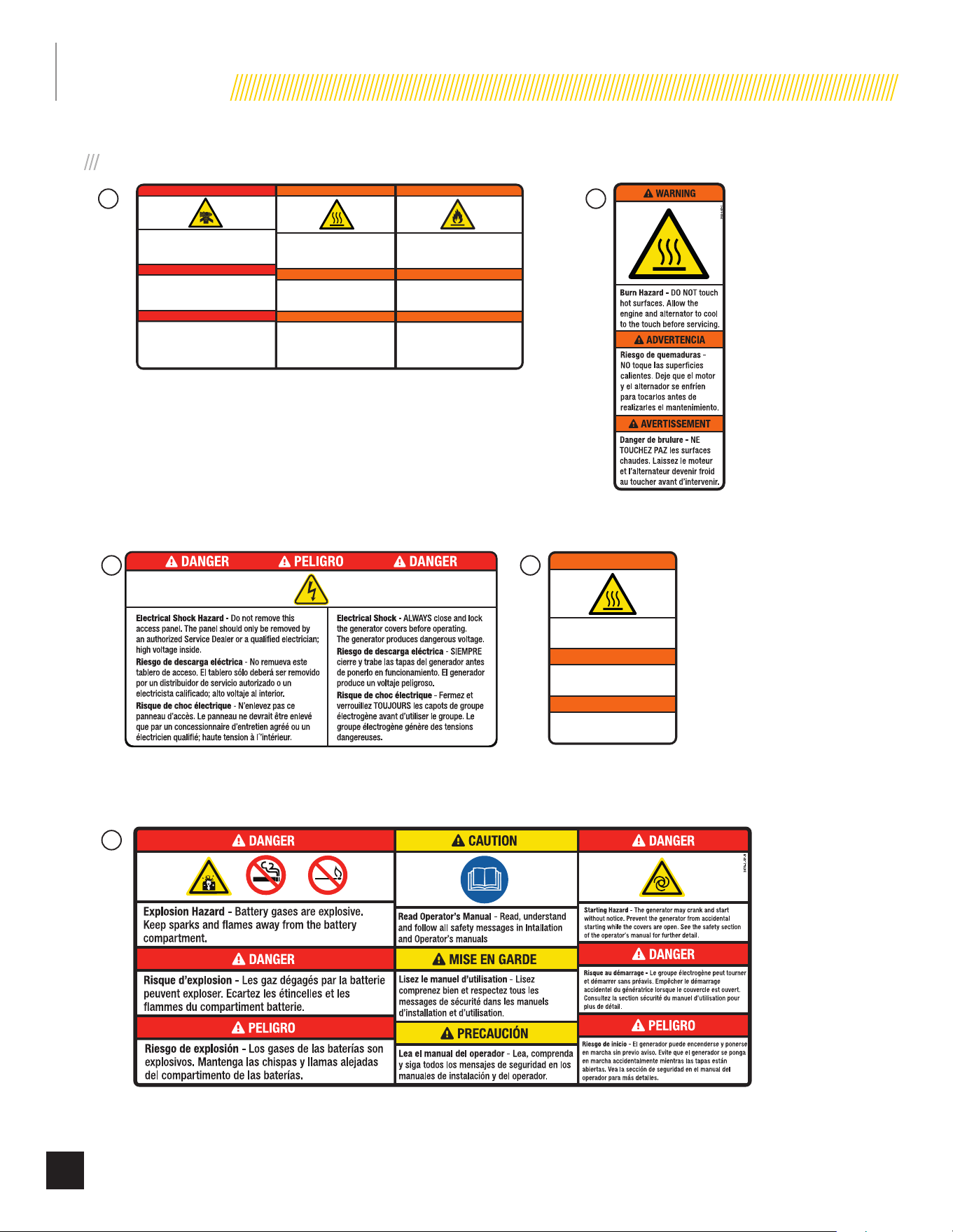
SAFETY LABELS
!
WARNING
!
All safety labels must be legible to
alert personnel of safety hazards.
• Replace any illegible or missing label immediately.
Missing safety labels must be replaced in their
original position before the generator is operated.
• DO NOT operate the generator if there are missing
or badly worn safety labels.
14
SAFETY
Part No. 101049
1
2510-L-SF
2483-L-SF
4622-L-SF 2473-L-SF
2470-L-SF
2
3
5
4
Poisonous Gas Hazard - Generator exhaust contains carbon
monoxide, a colorless, odorless, poisonous gas. Breathing
carbon monoxide will cause nausea, dizziness, fainting or
death. If you start to feel dizzy or weak, get to fresh air
immediately.
Risque d’empoisonnement par le gaz - Les gaz
d'échappement de la génératrice contiennent du monoxyde de
carbone, un gaz toxique incolore et inodore. L'inhalation de
monoxyde de carbone provoque des nausées, des
étourdissements, des évanouissements ou la mort. Si vous
commencez à vous sentir étourdi ou faible, rendez-vous
immédiatement à l'air frais.
Riesgo de gas venenoso - Los gases de escape del
generador contienen monóxido de carbono, un gas incoloro,
inodoro y venenoso. Respirar monóxido de carbono provoca
náuseas, mareos, desmayos o la muerte. Si empieza a
sentirse mareado o débil, busque aire fresco inmediatamente.
DANGER
PELIGRO
2510-L-SF-E
Fire Hazard - ALWAYS keep the surrounding area
near generator clean and free of debris and/or dry
vegetation. The generator may create sparks while
operating.
Risque d’incendie - Nettoyez TOUJOURS la surface
à proximité du groupe électrogène et enlevez les
débris et/ou la vegétation sèche. Le groupe
électrogène peut générer des étincelles pendant
son fonctionnement.
Riesgo de incendio - SIEMPRE mantenga el área
circundante cerca del generador limpia y libre de
escombros y/o vegetación seca. El generador puede
crear chispas mientras está en funcionamiento.
WARNING
ADVERTENCIA
Burn Hazard - DO NOT touch hot surfaces.
Avoid contact with exhaust components
and gases.
Risque de brûlure - NE touchez PAS les
surfaces chaudes. Evitez le contat avec les
composants et les gaz d’échappement.
Riesgo de quemaduras - NO toque las
superficies calientes. Evite el contacto con
los componentes de escape y gases.
WARNING
ADVERTENCIA
DANGER
AVERTISSEMENT
AVERTISSEMENT
2473-L-SF-C
Burn Hazard - DO NOT touch hot surfaces.
Avoid contact with exhaust components
and gases.
Risque de brûlure - NE touchez PAS les
surfaces chaudes. Evitez le contat avec les
composants et les gaz d’échappement.
Riesgo de quemaduras - NO toque las
superficies calientes. Evite el contacto con
los componentes de escape y gases.
WARNING
ADVERTENCIA
AVERTISSEMENT
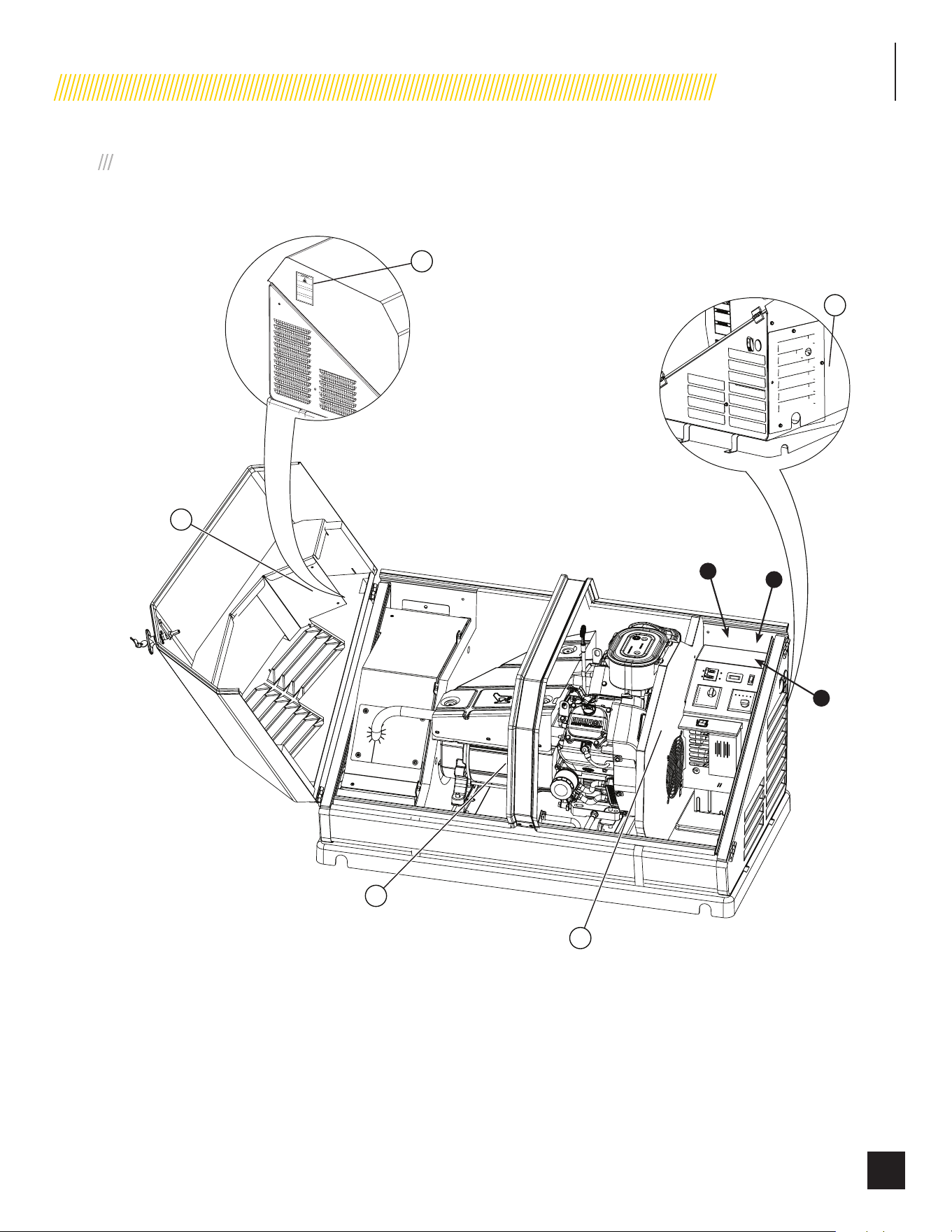
SAFETY LABELS ON UNIT
15
SAFETY
Part No. 101049
!!
5
2
1
4
3
!
A) Serial number location
B) Nameplate
C) NFPA 37 Compliance
C
A
B
SAFETY, SERIAL/MODEL, NAMEPLATE LABEL LOCATIONS
The safety labels have specific placement and must be replaced if they are unreadable, damaged or missing.

SPECIFICATIONS
16
Part No. 101049
8.5 KW SPECIFICATIONS - MODEL 100199
Home Standby Generator
Maximum continuous power, LPG (Propane) 8.5 kW
Maximum continuous power, NG (Natural Gas) 7.5 kW
Rated voltage 120/240
Amps 70.8/35.4 LPG, 62.5/31.25 NG
Harmonic distortion Less than 5%
Main line circuit breaker 35.5 amp
Phase Single
Frequency 60 Hz
Unit weight 365.1 lb. (165.6 kg)
Size (L × W × H) 49.1 × 28 × 28.3 in. (124.7 × 71 × 72 cm)
Engine
Type Champion OHV
No. of cylinders 1
Displacement 439cc
Cylinder block Aluminum with cast-iron sleeve
Ignition system Solid state – magneto
Spark plug F7RTC (NGK BPR7ES)
Governor Mechanical
Starter Electric 24V DC
Oil capacity - At manufacturing 1.2 qt. (1.1 L)
Oil capacity - When draining oil and replacing oil filter 1.0 qt. (0.9 L)
Oil Type 0W-40 Full Synthetic*
RPM 3600
Controls
Mode switch auto Auto start on utility failure
Mode switch manual Starts on demand
Mode switch off Stops unit/control and charger active
Ready to run/maintenance messages Standard
Programmable start delay Standard
Engine start sequence Standard
Starter lockout Standard
Battery charger/low battery indicator Standard
Charger fault Standard
AVR over voltage protection Standard
Low oil protection Standard
Safety fused Standard
Overcrank/overspeed/underspeed protection Standard
* Serial Number Y2212230069+: Unit comes with oil pre-filled in unit.
Serial Number < Y2212230069: Unit does not come with oil. You must ADD OIL before starting the unit.
**After 5 hours, change oil per maintenance schedule. The recommended oil type for typical use is 0W-40 full synthetic oil. However, using the listed conventional oils shown in the “Recommended
Engine Oil Type” chart may be used for typical use. If running generator in extreme temperatures, refer to the “Recommended Engine Oil Type” chart.

SPECIFICATIONS
17
Part No. 101049
CHAMPION 439CC ENGINE
The 439cc engine was initially developed by Champion for use in Champion portable generators. The single cylinder, overhead design
provides high output, efficient operation, low maintenance and demonstrated long life.
Based on the engine’s power, performance and reliability, it was selected to power the 8.5kW Champion Home Stand by generator. This
engine design has been used in production since 2008.
The following are the engine specifications:
Type ................................................. Champion OHV (Over head valve)
No. of Cylinders ................................ 1
Displacement ................................... 439cc
Cylinder Block .................................. Aluminum with cast-iron sleeve
Cylinder Head ................................... Automotive harden valves and seats
Ignition System ................................ Solid state – magneto
Governor .......................................... Mechanical
Starter .............................................. Electric 24V DC
RPM ................................................. 3,600
Oil Capacity ...................................... 1.2 qt. (1.1 L)
CHAMPION 439CC ENGINE TORQUE SPECIFICATIONS
Crankcase Cover Bolts .................... 24.4 Nm (216 in.-lbs)
Connecting Rod Bolts ...................... 18 Nm (156 in.-lbs)
Rocker Cover Screws ...................... 5.4 Nm (48 in.-lbs)
Cylinder Head Bolts ......................... 39 Nm (29 ft-lbs) (348 in.lbs)
Intake Manifold Screws .................. 9.5 Nm (84 in.-lbs)
Carburetor to Intake Manifold ......... 9.5 Nm (84 in.-lbs)
Blower Housing ............................... 12.2 Nm (108 in.lbs)
Flywheel Nut ................................... 115 Nm (85 ft-lbs)
Ignition Coil Bolts ............................ 9.5 Nm (84 in.-lbs)
Starter Motor Bolts ......................... 24.4 Nm (216 in.-lbs)
Spark Plug ...................................... 20 – 30 Nm (14.8 – 22.1 ft-lbs) (178 in.lbs – 265 in.lbs)
Air Cleaner box to Carb ................... 9 Nm (84 in.-lbs)
Exhaust pipe nuts ........................... 18 Nm (13 ft.-lbs) (156 in.lbs)
MASTER MIXING ASSEMBLY JETS (CARBURETOR SYSTEM)
Idle/low-speed Jet .......................... 1.8-2.5 Nm (15.9-22.1 in. lbs)
Main Jet .......................................... 1.2-1.5 Nm (10.6-13.2 in. lbs)
SPECIFICATIONS
18
Part No. 101049
11-12.5 KW SPECIFICATIONS
Model 100152 100136
Home Standby Generator 11 kW 12.5 kW
Maximum continuous power, LPG (Propane) 11 kW 12.5 kW
Maximum continuous power, NG (Natural Gas) 10 kW 11 kW
Rated voltage 120/240
Amps 91.6/45.8 LPG, NG 104/52 LPG, 91.6/45.8 NG
Harmonic distortion Less than 5%
Main line circuit breaker 46 amp 52 amp
Phase Single
Frequency 60 Hz
Unit weight 425.5 lb. (193 kg)
Size (L × W × H) 49 × 28 × 28 in. (124.5 × 71 × 71 cm)
Engine
Type Milwaukee Series OHV Commercial V-Twin
No. of cylinders 2
Displacement 717 cc
Cylinder block Aluminum with cast iron sleeves
Ignition system Solid state – magneto
Spark plug F7RTC (NGK BPR7ES)
Governor Mechanical
Starter Electric 24V DC
Oil capacity- At manufacturing 1.6 US qt (1.5 L)
Oil capacity- When draining oil and replacing oil filter 1.0 US qt (0.9 L)
Oil Type 0W-40 Full Synthetic*
RPM 3600
Controls
Mode switch auto Auto start on utility failure
Mode switch manual Starts on demand
Mode switch off Stops unit/control and charger active
Ready to run/maintenance messages Standard
Programmable start delay Standard
Engine start sequence Standard
Starter lockout Standard
Battery charger/low battery indicator Standard
Charger fault Standard
AVR over voltage protection Standard
Low oil protection Standard
Safety fused Standard
Overcrank/overspeed/underspeed protection Standard
* 100152 - Unit ships without oil.
100136 Serial Number Y2212200069+: Unit comes with oil pre-filled in unit.
Serial Number < Y2212200069: Unit does not come with oil. You must ADD OIL before starting the unit.
After 5 hours, change oil per maintenance schedule. The recommended oil type for typical use is 0W-40 full synthetic oil. However, using the listed conventional oils shown in the “Recommended
Engine Oil Type” chart may be used for typical use. If running generator in extreme temperatures, refer to the “Recommended Engine Oil Type” chart.

SPECIFICATIONS
19
Part No. 101049
CHAMPION 717CC ENGINE
The 717cc engine was developed by Champion Engine Technology for use in Champion home standby generators. The V-Twin cylinder
design provides high output, efficient operation, low maintenance and demonstrated long life.
Based on the engine’s power, performance and reliability, it was selected to power the 12.5kW Champion Home Standby Generator. This
engine design has been used in production since 2015.
The following are the engine specifications:
Type ................................................. Milwaukee Series OHV Commercial V-Twin
No. of Cylinders ................................ 2
Displacement ................................... 717cc
Cylinder Block .................................. Aluminum with cast-iron sleeve
Cylinder Head ................................... Automotive harden valves and seats
Ignition System ................................ Solid state – magneto
Governor .......................................... Mechanical
Starter .............................................. Electric 24V DC
RPM ................................................. 3,600
Oil Capacity ...................................... 1.6 qt. (1.5 L)
CHAMPION 717CC ENGINE TORQUE SPECIFICATIONS
Crankcase Cover Bolts .................... 27 Nm (20 lbf-ft)
Connecting Rod Bolts ...................... 12 Nm (9 lbf-ft)
Rocker Cover Screws ...................... 10 Nm (7 lbf-ft)
Cylinder Head Bolts ......................... 40 Nm (29.5 lbf-ft)
Intake Manifold Screws .................. 9.5 Nm (7 lbf-ft)
Carburetor to Intake Manifold ......... 9.5 Nm (7 lbf-ft)
Blower Housing ............................... 9 Nm (6.6 lbf-ft)
Flywheel Nut ................................... 196 Nm (145 lbf-ft)
Ignition Coil Bolts ............................ 9.5 Nm (7 lbf-ft)
Starter Motor Bolts ......................... 24.4 Nm (18 lbf-ft)
Spark Plug ...................................... 18 Nm (13.3 lbf-ft)
Air Cleaner box to Carb ................... 9 Nm (6.6 lbf-ft)
Exhaust pipe nuts ........................... 18 Nm (13.3 lbf-ft)
MASTER MIXING ASSEMBLY JETS (CARBURETOR SYSTEM)
Idle/low-speed Jet .......................... 1.9 Nm (1.4 lbf-ft)
Main Jet .......................................... 3.9 Nm (2.9 lbf-ft)
Fuel Inlet Chamber Screws ............. 2.9 Nm (2.1 lbf-ft)

SPECIFICATIONS
20
Part No. 101049
14 KW SPECIFICATIONS - MODEL 100237
Home Standby Generator
Maximum continuous power, LPG (Propane) 14 kW
Maximum continuous power, NG (Natural Gas) 12.5 kW
Rated voltage 120/240
Amps 116.6/58.3 LPG, 104/52 NG
Harmonic distortion Less than 5%
Main line circuit breaker 65 amp
Phase Single
Frequency 60 Hz
Unit weight 446.4 lb. (202.5 kg)
Size (L × W × H) 49 x 28 x 28 in. (124.5 x 71 x 71 cm)
Engine
Type Milwaukee Series OHV Commercial V-Twin
No. of cylinders 2
Displacement 754 cc
Cylinder block Aluminum with cast iron sleeves
Ignition system Solid state – magneto
Spark plug F7RTC (NGK BPR7ES)
Governor Mechanical
Starter Electric 24V DC
Oil capacity- At manufacturing 1.6 US qt (1.5 L)
Oil capacity- When draining oil and replacing oil filter 1.0 US qt (0.9 L)
Oil Type 0W-40 Full Synthetic*
RPM 3600
Controls
Mode switch auto Auto start on utility failure
Mode switch manual Starts on demand
Mode switch off Stops unit/control and charger active
Ready to run/maintenance messages Standard
Programmable start delay Standard
Engine start sequence Standard
Starter lockout Standard
Battery charger/low battery indicator Standard
Charger fault Standard
AVR over voltage protection Standard
Low oil protection Standard
Safety fused Standard
Overcrank/overspeed/underspeed protection Standard
*Unit ships without oil. Add oil before starting the HSB.

SPECIFICATIONS
21
Part No. 101049
CHAMPION 754CC ENGINE
The 754cc engine was developed by Champion Engine Technology for use in Champion home standby generators. The V-Twin cylinder
design provides high output, efficient operation, low maintenance and demonstrated long life.
Based on the engine’s power, performance and reliability, it was selected to power the 14kW Champion Home Standby Generator. This
engine design has been used in production since 2015.
The following are the engine specifications:
Type ................................................. Milwaukee Series OHV Commercial V-Twin
No. of Cylinders ................................ 2
Displacement ................................... 754cc
Cylinder Block .................................. Aluminum with cast-iron sleeve
Cylinder Head ................................... Automotive harden valves and seats
Ignition System ................................ Solid state – magneto
Governor .......................................... Mechanical
Starter .............................................. Electric 24V DC
RPM ................................................. 3,600
Oil Capacity ...................................... 1.6 qt. (1.5 L)
CHAMPION 754CC ENGINE TORQUE SPECIFICATIONS
Crankcase Cover Bolts .................... 27 Nm (20 lbf-ft)
Connecting Rod Bolts ...................... 12 Nm (9 lbf-ft)
Rocker Cover Screws ...................... 10 Nm (7 lbf-ft)
Cylinder Head Bolts ......................... 40 Nm (29.5 lbf-ft)
Intake Manifold Screws .................. 9.5 Nm (7 lbf-ft)
Carburetor to Intake Manifold ......... 9.5 Nm (7 lbf-ft)
Blower Housing ............................... 9 Nm (6.6 lbf-ft)
Flywheel Nut ................................... 196 Nm (145 lbf-ft)
Ignition Coil Bolts ............................ 9.5 Nm (7 lbf-ft)
Starter Motor Bolts ......................... 24.4 Nm (18 lbf-ft)
Spark Plug ...................................... 18 Nm (13.3 lbf-ft)
Air Cleaner box to Carb ................... 9 Nm (6.6 lbf-ft)
Exhaust pipe nuts ........................... 18 Nm (13.3 lbf-ft)
MASTER MIXING ASSEMBLY JETS (CARBURETOR SYSTEM)
Idle/low-speed Jet .......................... 1.9 Nm (1.4 lbf-ft)
Main Jet .......................................... 3.9 Nm (2.9 lbf-ft)
Fuel Inlet Chamber Screws ............. 2.9 Nm (2.1 lbf-ft)

SPECIFICATIONS
22
Part No. 101049
ALTERNATOR OVERVIEW
The alternator is made up with the following major components;
1. Brush holder assembly
2. Rear bearing carrier
3. 2 pole rotor (all copper wire)
4. Stator assembly (all copper wire)
5. Engine adapter
ROTOR ASSEMBLY
The alternator has a 2-pole rotor, which means the rotor has
a single south magnetic pole and a single north magnetic
pole. As the rotor spins, its magnetic field passes through the
stator assembly windings and voltage is induced into the stator
windings. This is known as induction. The rotor shaft has a
negative (-) slip ring and a positive (+) slip ring, with the negative
(-) nearest the bearing carrier. The rotor shaft is held in place
with single through bolt.
STATOR ASSEMBLY
The stator houses, AC power windings and excitation windings.
It is held in place with 4 bolts that pass through the bearing
carrier and engine adapter, then attached to the engine mounting
flange. In combination with the rotor assembly, they generate the
electrical out-put of the HSB.
BRUSH HOLDER AND BRUSHES
The brush holder is a component that holds the brushes in a
stationary position enabling them to maintain contact with the
rotating surface commutator rings on the rotor. The brush holder
is attached to the rear bearing carrier by means of a M5 x 20
bolt and a location tab. A negative (-) brush and a positive (+)
brush are retained in the brush holder. The negative (-) brush
rides on the slip ring nearest the bearing carrier. The brushes are
spring loaded to maintain contact.
A RED wire connects to the positive (+) brush and a BLACK
wire to the negative (-) brush. Rectified and regulated excitation
current, as well as current from the field boost circuit, are
delivered to the rotor windings via the RED wire, and the positive
(+) brush and slip ring. The excitation and field boost current
passes through the windings and to the frame ground via the
negative (-) slip ring and brush, and the BLACK wire.
The current flow creates a magnetic field around the rotor having
a flux concentration that is proportional to the amount of current
flow.
23
Part No. 101049
UNPACKING
UNPACKING
!
WARNING
The HSB weighs more than 300 lbs.
(136 kg). Use the aid of additional
assistants and exercise caution during
installation.
Inspect the generator for damaged or loose parts. DO NOT
operate the generator if any components are damaged or loose.
Contact your dealer for assistance.
1. Cut banding straps.
2. Remove top lid.
3. Remove center cardboard supporting rib.
4. Lift cardboard housing and set aside with all other trash.
5. Remove plastic covering and discard.
6. Remove 4 securing clamps. Save if going to use anchor
bolts to secure to concrete pad.
7. Insert 2 lifting rods (not supplied) into lifting notches at
each end of the base.
8. Discard all shipping materials and recycle if possible.
NOTICE
• If you know length of run for wires you may want to install
the ATS communication wires and voltage wires now
before setting unit to industry 1st 17.7 in. from fire rated
wall and when code permits. Install the wires, some of
the gas delivery pipes and flex hose now while you have
ample room and at tailgate height is much easier than
when in place
• Cardboard can be used for kneeling

24
Part No. 101049
INSTALLATION
Champion HSB units have been run and tested at the
factory prior to shipment. They do not require any type of
break-in period.
GENERATOR SIZING
Proper sizing is crucial to ensure that you purchase a model that
will supply enough power to your home during a power outage.
You need to determine the extent of the devices and appliances
you need to power. Remember that when you have lost power
(utility) at your home, you probably will not run every device or
appliance. Understanding that each device or appliance has an
electric consumption value generally referenced to as wattage or
kilowatts. There are a number of other factors to include of which
these two are important; continuous (running) watts and peak
(start-up) watts.
Continuous (running) watts is the amount of watts utilized
by the device or appliance while it is running and providing you
service.
Peak (start-up) watts is the requirement of the device or
appliance to start or kick-in. In others words, the amount of
power (watts) needed to start a device or appliance to initially get
the motors driving, requires additional power. Like your car, when
you accelerate to a specific speed the engine requires more
power to move your vehicle, once you have achieved the desired
speed your car is now in the running mode and can cruise along
at a maintained level at a lower RPM. The system doesn’t require
as much power for steady performance just getting there.
Most calculators or sizing guides add 20% and provide you with
an average usage to cover Continuous (running) and Peak (start-
up) wattage. This additional compensation is also for differing
wattage ratings among devices or appliances. Most devices or
appliances carry tags that reflect wattage usage and you could
find each label/tag and add them together to find a starting point
to the size of generator you would like to have.
Generators have built in limitations of output power (available
wattage or kilowatts). The rating output of the generator is listed
as Watts or kW (kilowatts). One thousand (1,000) watts is equal
to 1kW (kilowatt). Portable generators are generally smaller in
output and are mobile. HSB (home stand by) generators are
stationary or permanently mounted. The larger the unit the larger
the unit cost and installation costs. Example, most portable
generators are rated in WATTS and HSB (home stand by) are
rated in kW (kilowatts). 8000 watts is not more than 8kW, it’s
the same output. The larger the RATING the more output wattage
or kW you have available to power your home. The more output
equals move devices or appliances you may power.
There is a HSB sizing guide on Champion web,
www.championpowerequipment.com.
Before installing the generator, review SAFETY section starting
on page 8.
Have the generator installed by an authorized CPE dealer. Install
the equipment in compliance with the National Electrical Code
(NEC) and local codes. This could include electrical and fuel
supply permits and certified installers. For Canadian installations,
refer to Canadian Electrical Code (CEC).
This generator is designed to be installed outdoors only.
Before installing the generator, obtain a building permit and
contact your local utility companies to mark the locations of
underground cables and pipes.
INSTALLATION
25
Part No. 101049
PLACEMENT & INSTALLATION GUIDELINES FOR CHAMPION HOME
STANDBY GENERATORS TO REDUCE THE RISK OF FIRE
NATIONAL FIRE PROTECTION ASSOCIATION (NFPA) STANDARD NFPA 37
REQUIREMENTS AND TESTING
REQUIREMENTS:
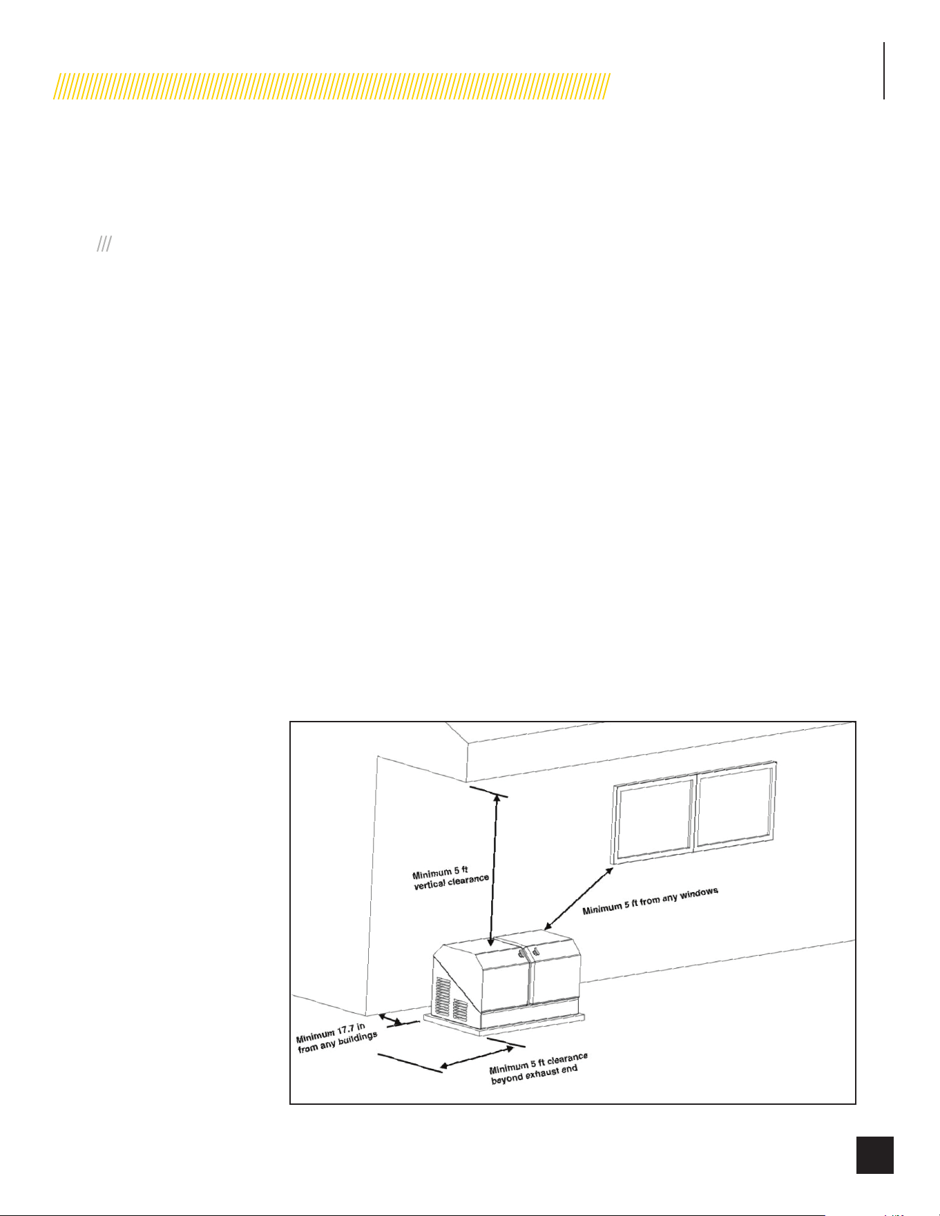
NFPA 37 2010, section 4.1.4, Engines Located Outdoors.
Engines, and their weatherproof housings if provided, that are
installed outdoors shall be located at least 1.5 m (5 ft.) from
openings in walls and at least 1.5 m (5 ft.) from structures
having combustible walls. A minimum separation shall not be
required where either of the following conditions exist:
1. The adjacent wall of the structure has a fire resistance
rating of at least 1 hour.
2. The weatherproof enclosure is constructed of
noncombustible materials and has been demonstrated
that a fire within the enclosure will not ignite combustible
materials outside the enclosure.
ANNEX A EXPLANATORY MATERIAL
A.4.1.2 (2) Means of demonstrating compliance are by means of
full-scale fire tests or by calculating procedures, such as those
given in NFPA 555, Guide on Methods for Evaluating Potential for
Room Flashover.
To comply with condition 2 the weatherproof enclosure has
been constructed of non-combustible materials and full-scale
fire tests have been performed to demonstrate that a fire within
the enclosure will not ignite combustible materials outside the
enclosure.
Based on this testing and the requirements of NFPA 37, Sec.
4.1.4, the guidelines for installation of the Champion home
standby generator are changed to 17.7 inches (45 cm) from
the backside of the generator to a combustible wall. All
other location and distances remain the same as noted in the
Operators and Installation manuals.
These guidelines are based upon fire testing of the generator
enclosure and Champion’s requirement for air flow for proper
operation. Local codes may be different and more restrictive.

INSTALLATION
26
Part No. 101049
INTERTEK GROUP PLC LABEL
LOCATED INSIDE THE GENERATOR, NEXT TO THE GENERATOR’S DATA LABEL
1193-L-PR-A
ID: 170800364HZH-001
Conforms to / Conforme à:
NFPA 37 4.1.4 CL. 2
K 2945 135 --- ---
ColorsAPN 1193-L-PR-A
REV B
Size 60 x 24 mm
Artwork Notes
3mm corner radius; 2mm safe margin;
white to be
printed shown in 50% process magenta
Revision Changes
B: delete “102358”
This artwork belongs to Champion Power Equipment. The contents are confidential and privileged and shall not be disclosed to or used by or for
outside parties without the explicit consent of Champion Power Equipment.
NFPA® 37 STANDARD FOR THE INSTALLATION AND USE OF STATIONARY COMBUSTION ENGINES AND GAS TURBINE
The National Fire Protection Association (NFPA) standard NFPA 37 establishes criteria for minimizing the hazard of fire during the
installation and operation of stationary combustion engines. NFPA 37 limits the spacing of an enclosed generator from openings in walls,
structures and combustible materials outside the enclosure.
NFPA 37 (2015): Section 4.1.4 stipulates that engines installed outdoors shall be located at least 5 ft. (1.5 m) from structures having
combustible walls. Further, a minimum separation shall not be required where the following conditions exist:
1. All walls of the structure that are closer than 5 ft. from the engine enclosure have a fire resistance rating of at least 1 hr., or
2. The weatherproof engine enclosure is constructed of noncombustible materials, and it has been demonstrated that a fire within the
enclosure will not ignite combustible materials outside the enclosure.
Intertek Group PLC performed a full-scale fire test under a worst-case fire scenario within the stationary generator enclosure to determine
the ignitability of combustible material near the stationary generator. The enclosure is made of non-combustible materials and the results
and conclusions of the test indicate that a fire within the enclosure would not pose any risk of ignition to nearby combustible materials
or structures. Intertek Group PLC is certifying that this model complies with clause (2) of Section 4.1.4 of NFPA 37 when installed at a
minimum distance of 450 mm (17.7 in.) from a combustible wall.
INSTALLATION
27
Part No. 101049
SITE SELECTION, PREPARATION
AND PLACEMENT
These items are important to the overall performance of the
HSB generator. Many items covered in this section are not
optional and are requirements under Federal, State and Local
codes. As with all generators, your generator must be installed
in accordance with current NFPA-37, NFPA 54, NFPA 58 and
NFPA-70 standards. Contact your local electrical inspector or city
hall to insure you are aware of all codes and regulations. Install
the equipment in compliance with the National Electric Code
(NEC). For Canada installations, refer to Canadian Electrical Code
(CEC). Contact your natural gas supplier to verify that increased
BTU gas demand can be handled with the existing NG meter. The
same should done for LPG fueled generators. This generator in
the enclosure is designed to be installed outdoors only.
Champion HSB units are run and tested at the factory prior to
being shipped. They do not require any type of break-in period.
SUGGESTED SITE SELECTION
The installation of the HSB must comply strictly with NFPA 37,
NFPA 54, NFPA 58 and NFPA 70 standards.
The Champion HSB is shipped from the factory set up for natural
gas (NG) fuel. The HSB can be converted to LPG if required.
Orifices in the master mixer assembly (carburetor) MUST be
changed. The LPG orifices are shipped with the unit and include
installation instructions.
Install the unit in a location where the sump pump discharge,
rain gutter downspouts, roof run off, landscape irrigation, natural
ponding or water sprinklers will not flood the unit or spray the
enclosure entering any inlet or outlet opens.
Position the unit in an area where prevailing winds will carry
the exhaust gas away from any potentially occupied building or
structure.
Install the unit where leaves, grass, snow, ect., will not obstruct
air inlet and outlet openings. If prevailing winds cause blowing or
drifting, you may consider building a windbreak, planting trees or
shrubs within the guidelines and codes applicable.
Watch out for roof overhangs. Snow, ice or rain shouldn’t be
permitted to accumulate on the roof and then cascade onto the
unit.
!
DANGER
Engine exhaust from the unit is hot
and dangerous.
Exhaust must be allowed to dissipate into a free
air zone as listed in the applicable codes with no
obstructions.
Direct the HSB exhaust away from or parallel to the building or
structure. DO NOT direct the HSB exhaust toward a potentially
occupied building, structure, windows, doors, ventilation intakes,
soffit vents, crawl spaces, open garage doors or other openings
where exhaust gas could accumulate and enter inside or be
drawn into potentially occupied buildings or structures.
Install the unit on higher ground where water levels will not rise
and endanger it. This unit shouldn’t be operated in standing
water.
DO NOT place HSB waterproof enclosure under a deck or other
type of structure that may confine or restrict airflow. Operate
HSB only outdoors, where adequate ventilation and air movement
is available. Avoid installations under decks, inside garages or
carports, in basements, along home exterior within 5 feet (1.5m)
of home vent, roof overhang vents, a window that can be opened,
or other such home invasion points. Use the same precautions
when installing HSB at property line, close to a neighbor’s home,
or any building or structure that houses animals.
!
DANGER
Running engines give off carbon
monoxide, an odorless, colorless,
invisible, poison gas.
Breathing carbon monoxide will cause fatigue,
headache, dizziness, vomiting and in prolonged
conditions, even death. Carbon monoxide detectors
MUST be installed and maintained indoors according
to the manufacturer’s instructions/recommendations.
Smoke alarms cannot detect carbon monoxide gas.
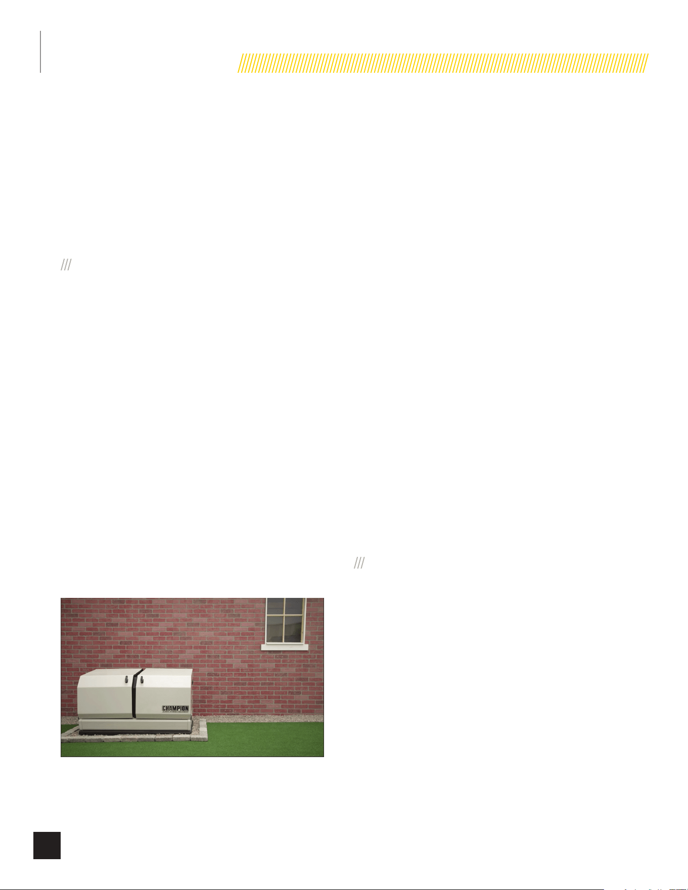
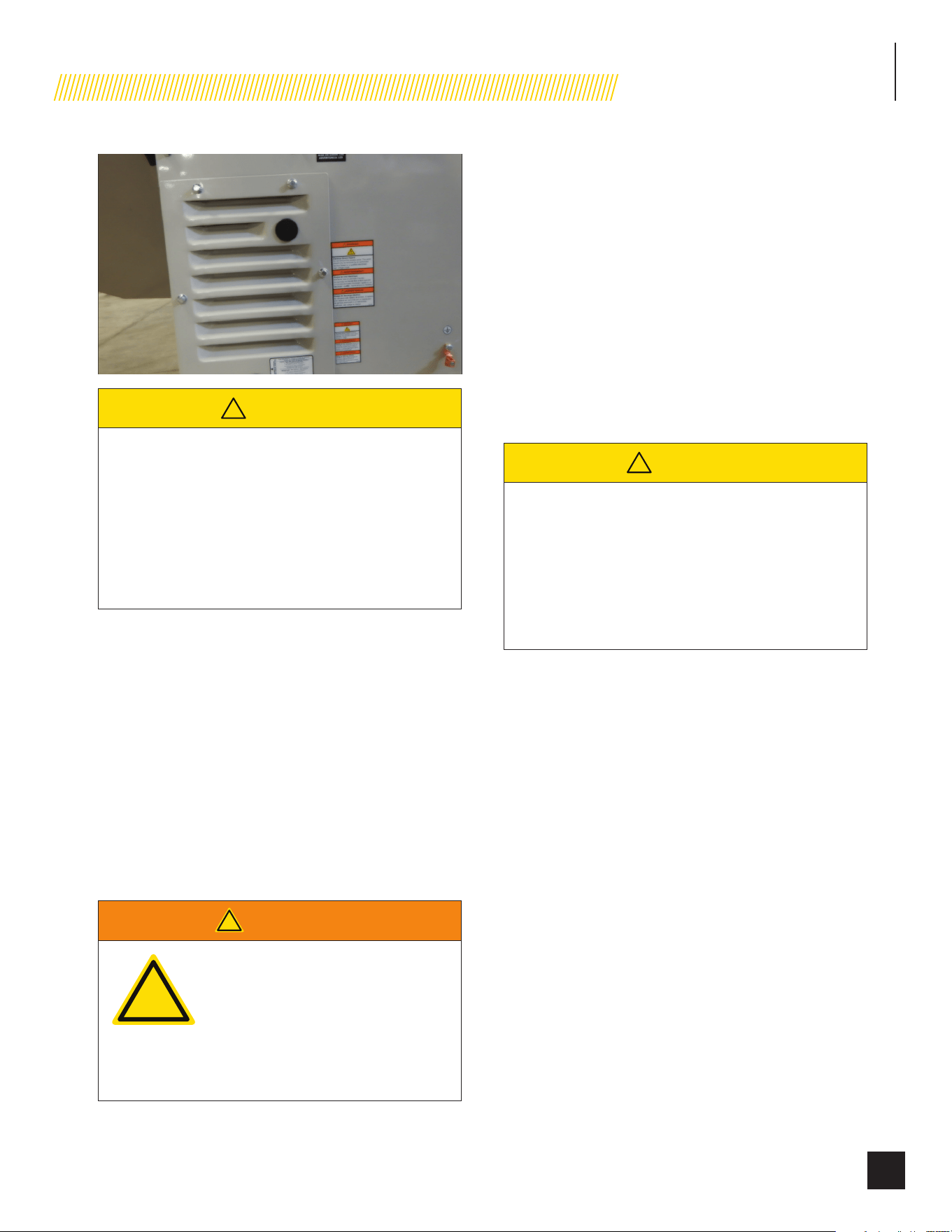
The back of the HSB locates the fuel and wire entry points. When
placement/mounting is done this side generally faces the closest
point to each of those sources.
INSTALLATION
28
Part No. 101049
It is always recommended to prepare a drawing showing location
of HSB, typical gas utility approach, circuit connections and full
load connections.
Similar considerations should be given to the location of the ATS
(automatic transfer switch) in relationship to the HSB generator.
The closer to both the fuel meter and the main utility panel
the better. The key point here is, the closer to fuel meter is the
suggested direction to go, wire is cheaper to run and more
flexible.
SUGGESTED PREPARATION
A concrete pad can be poured or purchased through Champion
(model 100616) and the HSB secured to it. In some areas a
concrete pad is required due to high wind potential. Check
local codes to see what type of mounting base is required. If a
concrete pad is required, all federal, state and local codes should
be followed. Unless mandated by federal, state or local code, a
concrete pad is not required.
If no concrete pad is being used, Champion recommends using
a mixture of pea gravel and sand or crushed stone for placement
of the mounting pad. The mounting pad MUST be level. The
gravel mixture or crushed stone is to permit water runoff,
drainage and reduce ponding of water around the HSB.
Dig an area 5 inches (12.7 cm) deep that is 6 inches (15.2 cm)
longer and wider than the foot print of the HSB. The HSB is 49
inches long × 28 inches wide (124.5 cm long × 71 cm wide).
Cover the dugout area with a weed barrier or landscape cloth if
desired.
Fill the area with pea gravel and sand mixture or crushed stone.
Final stone level must be 2 or 3 inches higher than the original
ground level to ensure water run-off and drainage.
Compact the fill, this is to provide a firm base for the HSB.
Remember the final stone level must be 2 or 3 inches higher
than the original ground level to ensure water run-off and
drainage.
TOOLS REQUIRED
1. General SAE and Metric hand tools, wrenches, sockets
and screwdrivers.
2. Standard electrician’s hand tools, drill and bits.
3. Monometer (for checking fuel pressures).
4. Meter capable of measuring AC/DC Voltage and Frequency
5. Safety apparel
Inspect the unit. Carefully inspect the HSB for any damage
that may have occurred during shipment and delivery. If loss
or damage is noted at the time of delivery, have the person(s)
making delivery note all damage on the freight bill and affix
their signature under the consignor’s memo of loss or damage.
If loss or damage is noted after delivery, separate the damaged
materials and contact the carrier for claims procedures. Parts
damaged in shipping are not covered under Champion warranty.
Unbox the unit, by removing the exterior shipping carton. The ATS
is included, remove the packaging and lift it out. Remove the 4
shipping brackets, 2 on each end that hold the HSB to the wood
shipping pallet. This pallet is for shipping/transportation only and
cannot be used as a mounting pad in any form. Exercise caution
when removing the HSB from the wood pallet, dragging it off the
wood pallet will damage the HSB base. The HSB must be lifted
from the wood pallet to separate.
Contact your natural gas (NG) supplier about the meter size. Most
meters must be replaced with a larger BTU size, due to a larger
demand of BTU’s from the HSB and appliances during operation
(utility outage). This also applies to HSB utilizing LPG.
SUGGESTED PLACEMENT
The Site Selection has been completed, all federal, state and
local codes have been reviewed and applied as mandated by the
NFPA standards and all other related codes/standards.
Preparation has been completed and everything has been
properly prepared to place the HSB.
The rear right side of the HSB locates the fuel and wire entry
points. When placement is done this side generally faces the
closest point to each of those sources for fuel and wire entry.
INSTALLATION
29
Part No. 101049
!
CAUTION
The HSB weighs approximately 300-400 lbs
(136kg - 181kg) depending on the model. Proper tools,
equipment and qualified personnel should be used in
all phases of handling and moving the HSB. Do not lift
or move the HSB without assistance. Do not lift the
unit by the roof or any other enclosure component as
damage to the HSB and possible injury of handling/
moving staff may occur.
Two (2) 5 foot (1.5 m) lengths of ¾ “steel pipe (supplied by
the installer), are required to lift the HSB. Insert the steel pipes
through the lifting holes located near the HSB base in the
composite pad, on each end.
You may also lift the HSB using a properly rated strap, lift, hook
and hoist procedure attached to both steel lifting pipes, provided
that you use spreader bars to ensure that the belts, chains or
cables DO NOT touch/contact the HSB.
Once the HSB has been placed, check to make sure it is level. If
it isn’t, make adjustments prior to installation procedures start.
INSTALLATION PREPARATION
!
WARNING
!
Improper installation can result in
personal injury and damage to the
generator. It may also result in the
warranty being suspended or voided.
All the instructions must be followed
including location clearances and
pipe size.
Once Site Selection, Preparation and Placement has been
completed, you can proceed to Installation Preparation. Without
these in place you may encounter problems moving forward.
There are a number of key items that MUST be addressed prior
to the physical installation of the HSB. The installation of the HSB
must comply strictly with all applicable codes, standards and
regulations (NFPA 37, NFPA 54, NFPA 58, and NFPA 70).
Check and confirm that the HSB on board controls are “ALL” in
the “OFF” position. This includes; Control panel circuit breaker,
exercise control and both LED controllers.
Champion HSB units have been run and tested at the factory
prior to being shipped. They do not require any type of break-in
period.
!
CAUTION
The HSB is shipped with oil in the engine.
Never operate the HSB with the engine oil level below
the “ADD” mark on the dipstick, doing so could damage
the engine. Check the oil level and add the appropriate
viscosity and amount indicated on the oil dipstick full
line. Oil viscosity 0W-40 full synthetic. Refer to Owner’s
manual.
IN THE THIS SEGMENT, “INSTALLATION PREPARATION, THE
FOLLOWING WILL BE COVERED;
1. Fuel Requirements and Recommendations
2. Fuel Consumption
3. NG Pipe Sizing, flexible fuel line
4. LPG Vapor Pipe Sizing, flexible fuel line
5. Converting to LPG
6. Full Flow Shut Off Valve
7. Sediment Trap
8. Checking Pressure with a Manometer
9. Battery Requirements, Installation & Service
INSTALLATION
30
Part No. 101049
1. FUEL REQUIREMENTS AND
RECOMMENDATIONS
The following NG and LPG fuel information is provided to assist
the fuel installer. This information should not be deemed to be
all inclusive or to conflict with local dry fuel codes. Consult your
local fuel supplier or Fire Marshall for guidance on proper local
codes and installations. Local codes will mandate correct routing
of gaseous fuel line piping around gardens, shrubs and other
landscaping to prevent any damage.
Special considerations should be given when installing the
HSB where local conditions include might flooding, tornadoes,
hurricanes, earthquakes and unstable ground. These are
considerations for the flexibility and strength of piping and their
connections.
NG is lighter than air and will collect in high areas. LPG is heavier
than air and will settle in low areas.
!
DANGER
Gaseous fuels such as NG and
LPG are highly explosive. Even the
slightest spark can ignite such fuels
and cause an explosion, which
could cause burns, fire or explosion
resulting in serious injury, property
damage or even death. NO leakage is
permitted.
Recommended fuels should have a BTU content of at least 1,000
BTU’s per cubic foot for NG, or at least 2,500 Btu’s per cubic foot
for LPG. Ask the fuel supplier for the Btu content of the fuel.
Before NG fuel lines plans are made, call your NG supplier,
provide them information on the amount cubic feet/hour and
the BTU’s/hour that the HSB will use, and ask if the NG meter
and primary regulator can accommodate the addition of the NG
generator. NG companies have different meters for increased
BTU demands. Utilize the “Fuel Consumption (BTU) Chart”
contained in this manual or the Installation Manual for your
specific HSB model.
Verify that the current gas meter is capable of providing
enough fuel flow to include household appliances and other
loads including the addition of the HSB. Check the NG primary
regulator, connected at the NG meter output. The correct primary
regulator is set at 6 to 8 inches water column. The existing
primary regulator may be undersized once the HSB is added.
The HSB engine can run on either NG or LPG. The HSB comes
equipped from the factory to run on NG. If your installation
requires the engine to run on LPG, orifices in the master mixer
assembly (carburetor) MUST be changed. The LPG orifices are
shipped with HSB. Refer to “Converting to LPG” in this manual or
the “Installation Manual” for your specific HSB model.
8.5 KW FUEL SYSTEM REQUIREMENTS
Fuel System
Requirements
LPG NG
Fuel supply inlet 3/4 in. NPT
Fuel supply
pressure
10 – 12 inch-H20.
(2.5 – 3.0 kPa
W.C.)
5 – 7 inch-H2O
(1.2 – 1.7 kPa
W.C.)
Maximum flow rate
@ 8.5 kW
146,667 Btu/hr 135,760 Btu/hr
11-12.5 KW FUEL SYSTEM REQUIREMENTS
Fuel System
Requirements
LPG NG
Fuel supply inlet 3/4 in. NPT
Fuel supply
pressure
10 – 12 inch-H20.
(2.5 – 3.0 kPa
W.C.)
5 – 7 inch-H2O
(1.2 – 1.7 kPa
W.C.)
Maximum flow rate
@ 11 kW
8.53 l/hr 5.208 m
3
/hr
14 KW FUEL SYSTEM REQUIREMENTS
Fuel System
Requirements
LPG NG
Fuel supply inlet 3/4 in. NPT
Fuel supply
pressure
10 – 12 inch-H20.
(2.5 – 3.0 kPa
W.C.)
5 – 7 inch-H2O
(1.2 – 1.7 kPa
W.C.)
Maximum flow rate
@ 14 kW
10.1 l/hr 5.3 m
3
/hr
Nominal Fuel Rating
LPG 2500 Btu/ft
3
NG 1000 Btu/ft
3
Install the fuel system in accordance with NEC and local codes.
The HSB is EPA Phase 3 certified for LPG and NG fuels.
INSTALLATION
31
Part No. 101049
2. FUEL CONSUMPTION
Air density is less at high altitudes, resulting in less available
engine power. Engine power will decrease 3.5% for each 1,000
feet (300 m) above sea level and 1% for each 10 degrees F
above 77 degrees F. Make sure these factors are considered
when determining total HSB load.
The gas supply and pipe MUST be sized at 100% load Btu
rating. Understand that as a specific fuel supply line pipe
diameter is extended in length, its ability to carry the volume of
gas diminishes in direct proportion. Improper fuel pipe sizing is
the number one reason for poor operating performance (hard
starting, output).
Required fuel pressure for NG is 5 – 7 inches water column.
Required fuel pressure for LPG vapor is 10 – 12 inches water
column. These are estimated fuel supply requirements listed.
Refer to “Fuel Consumption Chart” contained in this manual or
Installation Manual for your specific HSB model.
8.5 KW FUEL CONSUMPTION
Fuel Type Percent of Load Btu/hr
LPG
25% 74,121
50% 100,783
75% 126,563
100% 146,667
NG
25% 94,673
50% 108,369
75% 122,989
100% 135,760
11-12.5 KW FUEL CONSUMPTION
Fuel Type Percent of Load l/hr – m
3
/hr
LPG
0% 2.72 l/hr
50% 5.49 l/hr
100% 9.78 l/hr
NG
0% 1.82 m
3
/hr
50% 3.46 m
3
/hr
100% 5.61 m
3
/hr
14 KW FUEL CONSUMPTION
Fuel Type Percent of Load l/hr – m
3
/hr
LPG
0% 3.09 l/hr
50% 5.93 l/hr
100% 9.91 l/hr
Fuel Type Percent of Load l/hr – m
3
/hr
NG
0% 1.8 m
3
/hr
50% 3.3 m
3
/hr
100% 5.1 m
3
/hr
3. NG PIPE SIZING
The HSB leaves the factory set up for NG, no changes or
alteration need to be made if NG is the fuel source you are going
to use The following NG fuel information is provided to assist
the fuel installer. This information should not be deemed to be
all inclusive or to conflict with local dry fuel codes. Consult your
local fuel supplier or Fire Marshall for guidance on proper local
codes and installations. All piping must comply with NFPA 54
and related codes. Gas line connections should be made by a
certified plumber familiar with local codes.
Always use AGA approved gas pipe and a quality pipe sealant
or joint compound. The piping should conform to federal and
local codes, rigidly mounted and protected from vibration. Piping
should be black iron or steel to avoid reacting with the sulfur in
the fuel.
!
DANGER
NG is highly explosive. Even the
slightest spark can ignite and cause
an explosion, which could cause
burns, fire or explosion resulting in
serious injury, property damage or
even death. NO leakage is permitted.
Safety is important.
Gas pipe sizing is critical to the proper operation of the HSB. The
HSB fuel inlet size has no bearing on the proper gas pipe size
running to the HSB. Gas supply and pipe MUST be sized at 100%
load BTU rating. Understand that as a specific fuel supply line
pipe diameter is extended in length, its ability to carry the volume
of gas is diminished in direct proportion.
Pipe sizes are measured by inside diameter (ID) to include any
fittings, valves, elbows, tees or angles. Add 2.5 feet (.76 m) per
bend, tee or angle in the pipe line to the overall distance, for
each 90 degree elbow, add 8 feet (2.4 m) to the measurement.
Use a pipe sealant or joint compound approved for use with LPG/
NG on all threaded fittings to assure zero leakage.
A dedicated NG fuel supply line pipe and primary gas regulator is
mandatory for proper operation. A minimum of one (1) approved,
external manual full flow shutoff gas valve must be installed in
the fuel supply line pipe leading to the HSB. This line must be
easily accessible.
INSTALLATION
32
Part No. 101049
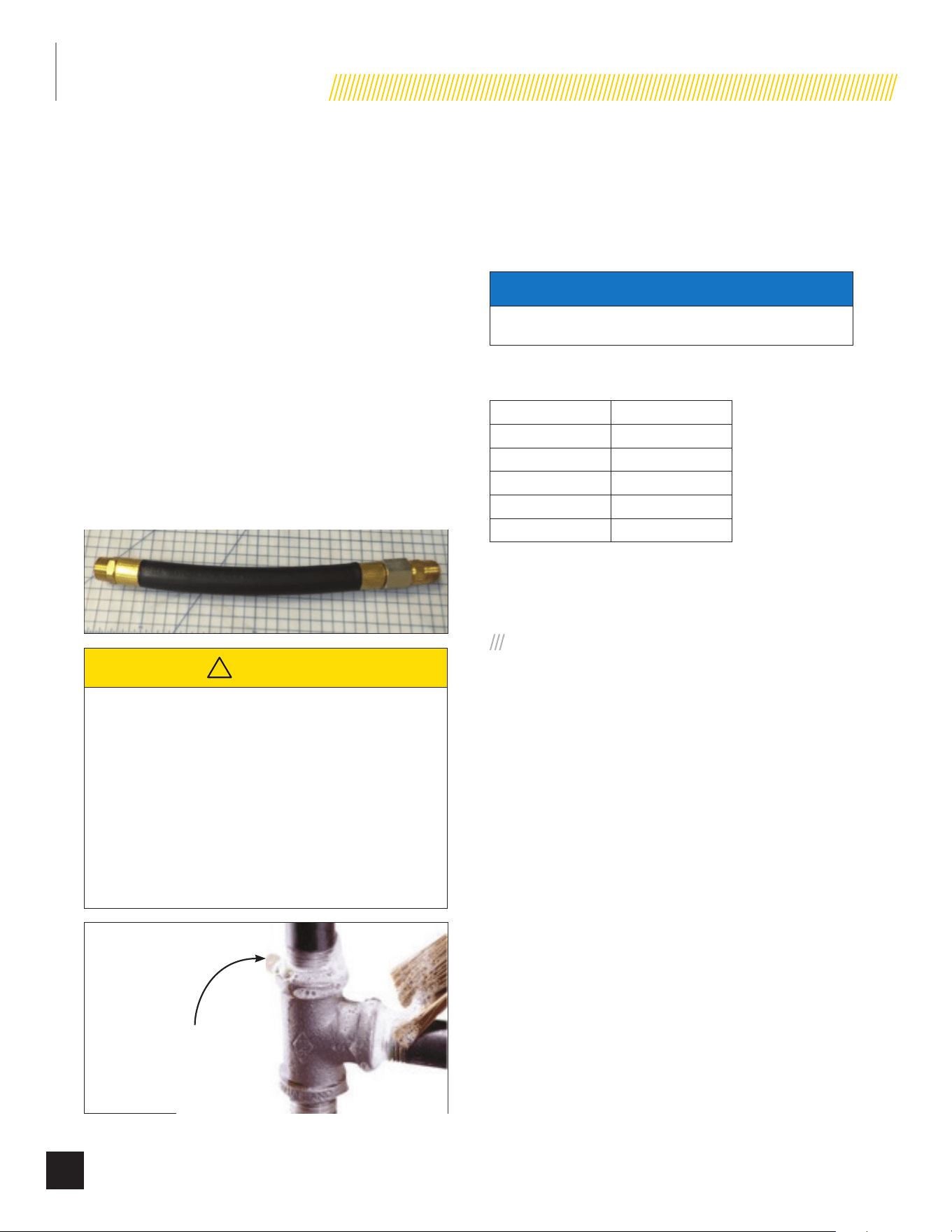
FLEXIBLE FUEL LINE
A flexible fuel line (enclosed with the HSB) is to be installed
between the stationary fuel supply line pipe and the fuel inlet
pipe to the HSB. The purpose of the flexible fuel line is to ensure
that vibration from the HSB does not cause a gas leak at one of
the connection points. The flexible fuel line is not to be installed
underground, in contact with any enclosure parts or contact
with the ground. The entire flexible fuel line must be visible for
periodic inspection and must not be concealed within nor contact
nor run through any wall, floor, partition or fence. Never bend
flexible fuel line to avoid using an elbow. Bending the flexible fuel
line decreases its ability to absorb vibrations and could restrict
the actual fuel flow. Because a HSB engine is prone to vibration,
a flexible piping connection to the gas supply is required.
Connect the HSB to the gas supply piping with an approved
flexible gas line according to local codes. The flexible gas line
also protects against settlement between the HSB pad and the
ridged gas supply piping.
!
CAUTION
Check for leaks by spraying all connection points
with a soap solution made of dishwashing liquid
and water. If you see bubbles, this indicates a leak
and the connection should be corrected. Check each
connection point, there should not be a visible bubbling
when soap solution applied. Installed piping must be
properly purged and leak tested, in accordance with
applicable codes and standards. A sediment trap
should be placed in the fuel supply pipe line to drain
any condensation.
Bubble indicates leak
Refer to the “Fuel Pipe Sizing Chart” contained in this manual or
the Installation manual for your specific HSB model. Champion
HSB units have been run and tested at the factory prior to
shipment. They do not require any type of break-in period.
FUEL PIPE SIZING CHART
NOTICE
Reduced pipe size will affect fuel delivery and performance.
Measure the pipe length from the generator fuel inlet to the
primary gas pressure regulator.
Pipe Length* NG
25 ft (8 m) 3/4 in. NPT
50 ft (15 m) 1 in. NPT
100 ft (30 m) 1 in. NPT
150 ft (46 m) 1-1/4 in. NPT
200 ft (61 m) 1-1/4 in. NPT
*Add 2.5 ft (0.76 m) per bend, tee or angle in the pipe line to
overall distance, for each 90 degree elbow, add 8 feet (2.4 m) to
the overall measurement.
4. LPG VAPOR PIPE SIZING
The HSB leaves the factory set up for NG. If you are going to fuel
the HSB with LPG you MUST change the Master Mixer Assembly
(carburetor system) for LPG usage. The HSB will not perform on
LPG if the carburetor system is not changed from NG to LPG.
Refer to “Converting to LPG” in this manual or the Installation
Manual of your specific HSB model. If your installation requires
the engine to run on LPG, a set of orifices in the Master Mixer
Assembly (carburetor system) MUST be changed. The LPG set of
orifices are enclosed (shipped) with the HSB.
The following LPG information is provided to assist the fuel
installer. This information should not be deemed to be all
inclusive or to conflict with local dry fuel codes. Consult your
local fuel supplier or Fire Marshall for final answers on proper
local codes and installation. All piping must comply with NFPA
54 and related codes. Gas line connections should be made by a
certified plumber familiar with local codes.
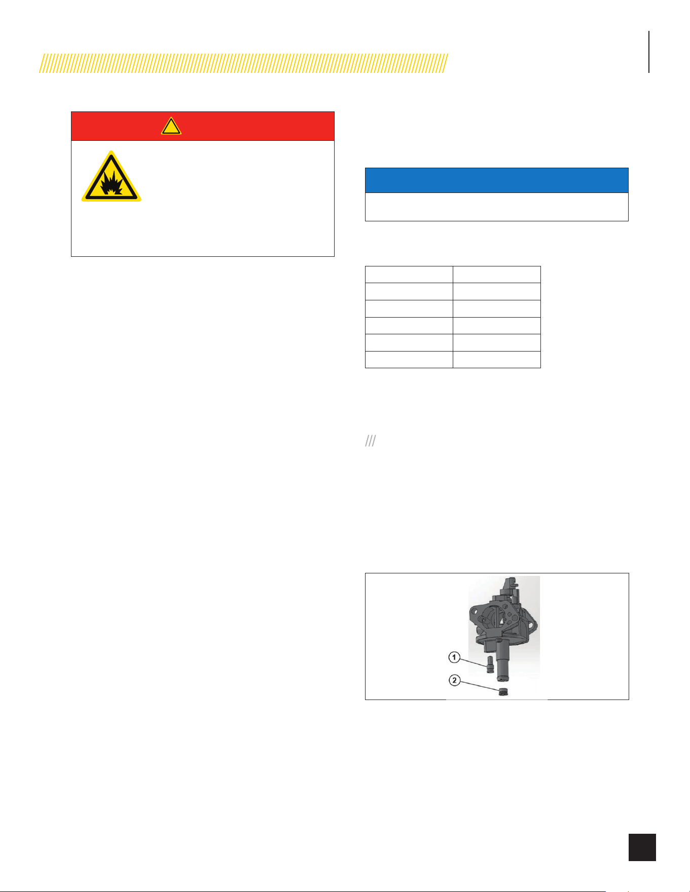
INSTALLATION
33
Part No. 101049
!
DANGER
LPG is highly explosive. Even the
slightest spark can ignite and cause
an explosion, which could cause
burns or fire resulting in serious
injury, property damage or even
death. No leakage is permitted.
Safety is important.
Gas pipe sizing is critical to the proper operation of the HSB. The
HSB fuel inlet size has no bearing on the proper gas pipe size
running to the HSB. Gas supply and pipe MUST be sized at 100%
load Btu rating.
Pipe sizes are measured by inside diameter (ID) to include any
fittings, valves, elbows, tees or angles. Add 2.5 feet (.76 m) per
any bend, tee or angle in the pipe to the overall distance. For
each 90 degree elbow, add 8 ft. (2.4m) to the measurement.
Use a pipe sealant or joint compound for use with LPG/NG on all
threaded fitting to assure zero leakage.
The LPG must be a vapor withdrawal system. The HSB will not
work on a liquid withdrawal system. Gas line connections should
be made by a certified plumber familiar with local codes.
New LPG tanks and existing LPG tanks already located at the
installation site, have a primary fuel regulator set and intended
for home heating and cooking. This regulator might not be
properly sized to accommodate the addition of the HSB. Contact
the local LPG supplier to properly size the fuel regulator.
Make sure the tank is sized large enough to provide the required
Btu’s for the HSB and all connected appliances.
The LPG fuel tank must have a dedicated primary fuel regulator
mounted at the tank fuel outlet point and set for 6 ounce
pressure, 10 -12 inch water column. A direct, dedicated fuel
line connected directly to the HSB mounted secondary regulator,
also set at 6 ounce pressure, 10 -12 inch water column. When
sizing the secondary regulator for LP applications be sure to note
the maximum individual load capabilities. This could impact HSB
starting performance if sized to small. It is not recommended
to reduce the fuel supply line pipe exiting the secondary
regulator unless to accommodate the flexible fuel line required
to install and shipped with the unit. The may result in starting or
performance issues with the HSB.
Make sure fuel supply line pipe includes an on/off external
manual full flow shut off gas valve at both the LPG tank and at
the point of connection to the HSB.
A sediment trap should be installed into the fuel supply pipe line
to drain any condensation.
FUEL PIPE SIZING CHART
NOTICE
Reduced pipe size will affect fuel delivery and performance.
Measure the pipe length from the generator fuel inlet to the
primary gas pressure regulator.
Pipe Length* LPG
25 ft (8 m) 3/4 in. NPT
50 ft (15 m) 3/4 in. NPT
100 ft (30 m) 1 in. NPT
150 ft (46 m) 1 in. NPT
200 ft (61 m) 1 in. NPT
*Add 2.5 ft (0.76 m) per bend, tee or angle in the pipe line to
overall distance, for each 90 degree elbow, add 8 feet (2.4 m) to
the overall measurement.
5. CONVERTING TO LPG
The engine is fitted with a dual Master Mixer Assembly
(carburetor system), which allows the HSB to run on either NG or
LPG. It has been configured at the factory to run on NG. If your
installation requires to run on LPG, an orifice in the Master Mixer
Assembly (carburetor system) must be changed. The LPG orifices
are shipped with the HSB.
8.5 KW MODELS
1. Loosen the clamp, disconnect the fuel delivery hose from
the bottom of the mixing valve.
2. Use a flat-head screwdriver to remove the idle/low speed
orifice (jet) counter clockwise and main orifice (jet) from
the mixing valve counter clockwise.
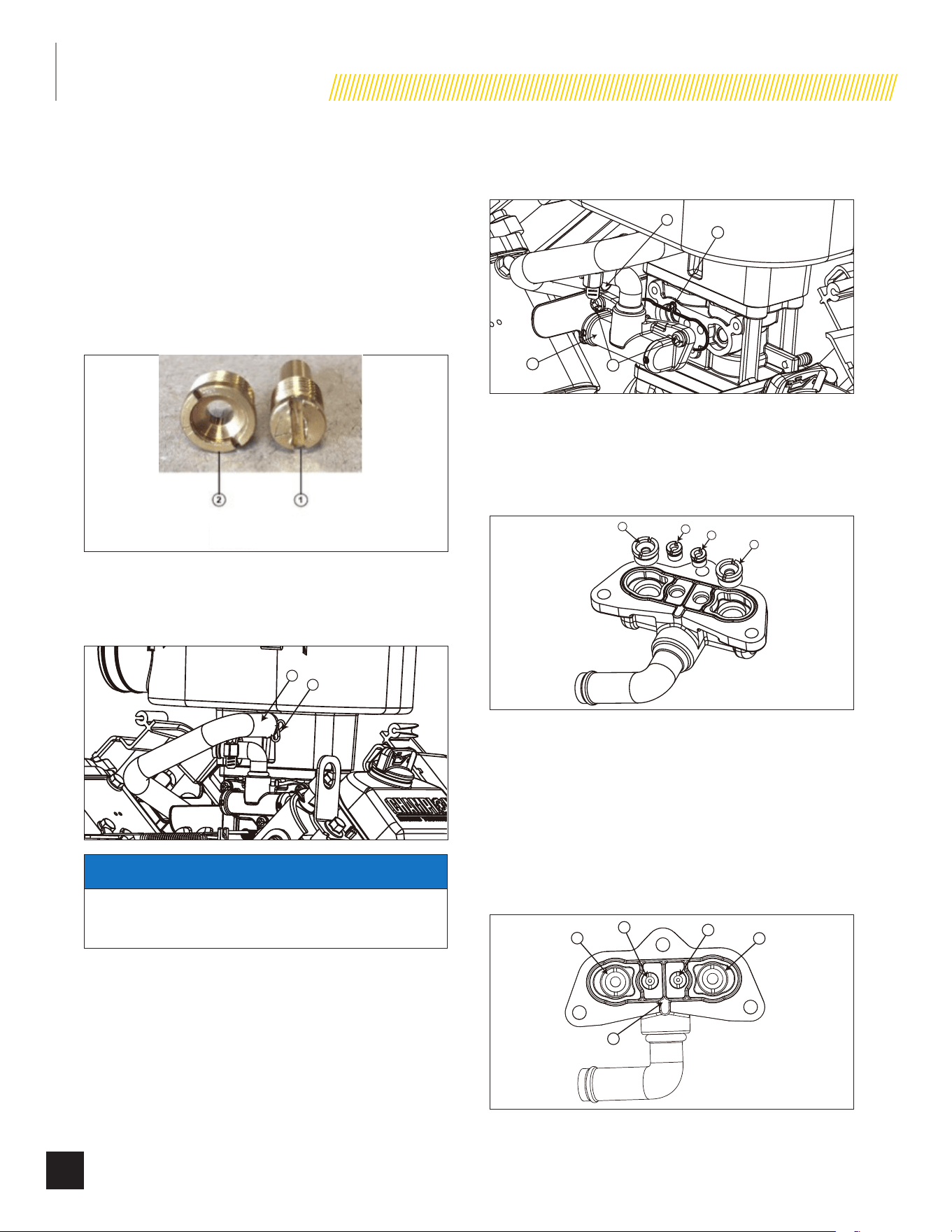
INSTALLATION
34
Part No. 101049
3. Install the LPG orifices (jets) in the mixing valve clockwise.
Tighten the low speed orifice (jet) to 15.9 – 22.1 lb.-in.
(1.8 – 2.5 N m). The main orifice (jet) to 10.6 – 13.2 lb.-
in. (1.2 – 1.5 Nm).
4. Re-install the fuel delivery hose and tighten the clap
securely. Check the connection for fuel leaks after
installing fuel supply.
5. LPG jet markings on face of jet; LPG main jet L41, LPG
idle jet L0
1. LOW SPEED JET
2. MAIN JET
11-12.5 KW MODELS
1. Remove breather tube (1) by loosening breather tube
clamp (2).
1
2
NOTICE
Cover gap in engine valley with cloth or rag to prevent jets
or fasteners from falling into the engine.
2. Remove fuel inlet chamber screws (3). Remove fuel inlet
chamber (4) along with fuel hose (5) and gasket (6).
4
5
6
3
3. Remove left side main jet (7), right side main jet (8), left
side slow jet (9) and right side slow jet (10). Recommend
tool for removing main jet: Special Tool (Part number
100908). Recommend tool for removing slow jet: Driver
Bit, 7/32 Slot - Flat Head
7
9
10
8
4. Install LPG jets and gasket (6) to fuel inlet chamber.
Left side main jet: Size #390 (11)
Right side main jet: #410 (12)
Left side slow jet: Size #130 (13)
Right side slow jet: #120 (14)
Main Jet Tightening Torque: 34.7 lb.-in (3.92Nm)
Slow Jet Tightening Torque: 17.3 lb.-in (1.96Nm)
6
11
13
14
12
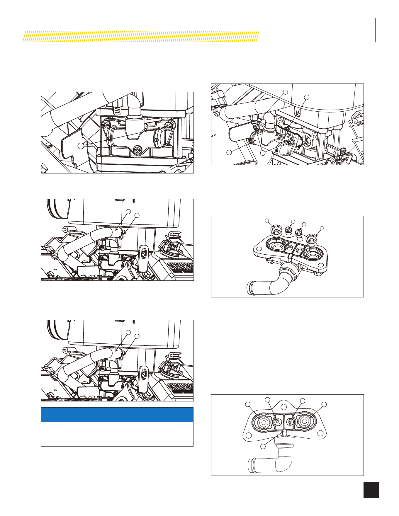
INSTALLATION
35
Part No. 101049
5. Install fuel inlet chamber to mixer body. Tighten fuel inlet
chamber screws (3). Screw Tightening Torque: 26.0 lb.-in
(2.94Nm).
3
6. Connect breather tube (1) to breather port and put clamp
(2) on breather tube.
1
2
14 KW MODELS
1. Remove breather tube (1) by loosening breather tube
clamp (2).
1
2
NOTICE
Cover gap in engine valley with cloth or rag to prevent jets
or fasteners from falling into the engine.
2. Remove fuel inlet chamber screws (3). Remove fuel inlet
chamber (4) along with fuel hose (5) and gasket (6).
4
5
6
3
3. Remove left side main jet (7), right side main jet (8), left
side slow jet (9) and right side slow jet (10). Recommend
tool for removing main jet: Special Tool (Part number
100908). Recommend tool for removing slow jet: Driver
Bit, 7/32 Slot - Flat Head
7
9
10
8
4. Install LPG jets and gasket (6) to fuel inlet chamber.
Left side main jet: Size #410 (11)
Right side main jet: #430 (12)
Left side slow jet: Size #130* (13)
Right side slow jet: #120* (14)
Main Jet Tightening Torque: 34.7 lb.-in (3.92Nm)
Slow Jet Tightening Torque: 17.3 lb.-in (1.96Nm)
*No slow jet required for NG.
6
11
13
14
12
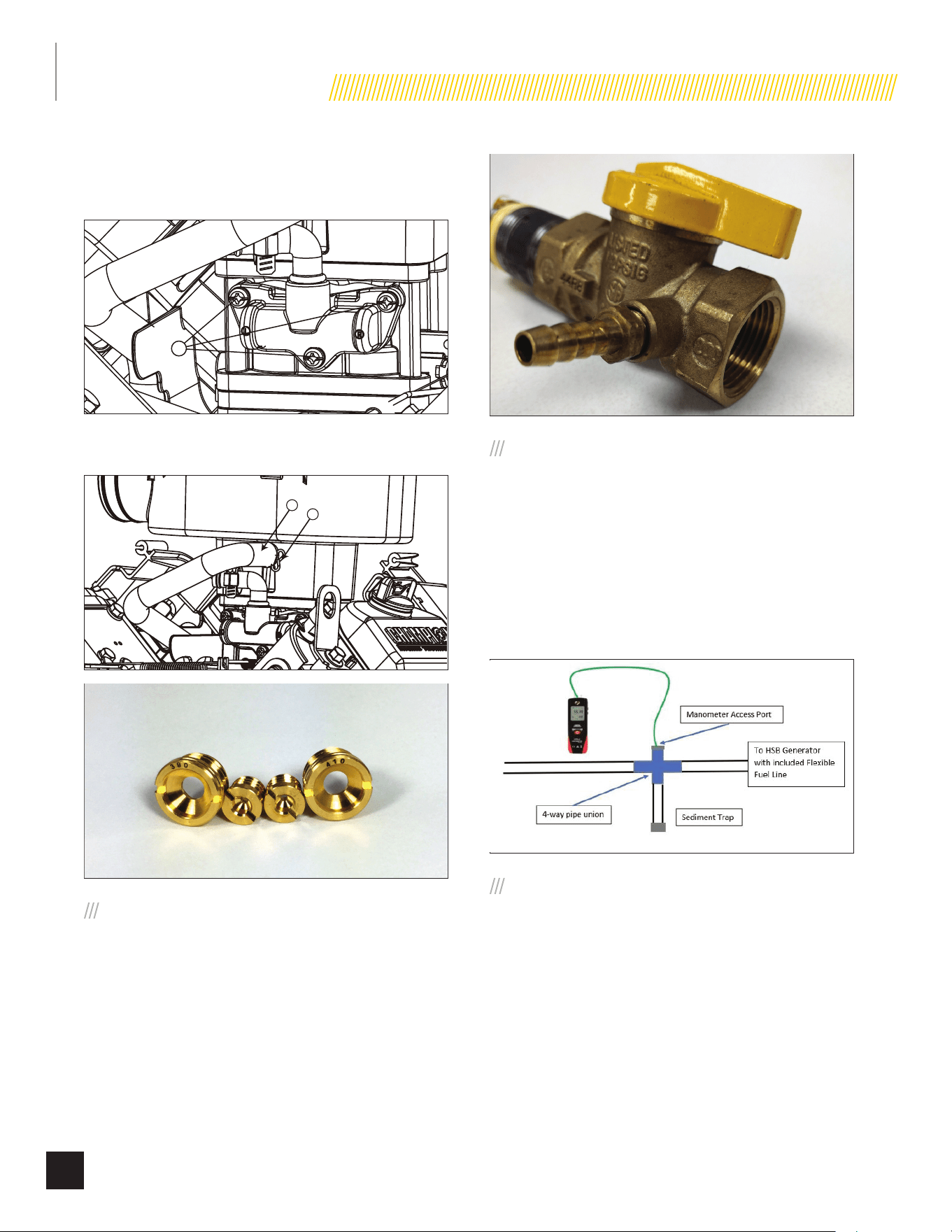
INSTALLATION
36
Part No. 101049
5. Install fuel inlet chamber to mixer body. Tighten fuel inlet
chamber screws (3). Screw Tightening Torque: 26.0 lb.-in
(2.94Nm).
3
6. Connect breather tube (1) to breather port and put clamp
(2) on breather tube.
1
2
6. FULL FUEL SHUT OFF
A minimum of one accessible, approved manual full fuel shutoff
valve shall be installed in the fuel supply line of the HSB.
A manual full fuel shut off valve should be installed inside the
building, for those locations with inside gas meters.
The full flow shut off valve should be installed in accordance with
all applicable codes and standards.
7. SEDIMENT TRAP
A sediment trap should be installed into the fuel supply line pipe
when using either NG or LPG to drain any condensation. Always
make sure the HSB is completely in the OFF position and the full
flow fuel shut off valve is closed before removing the sediment
trap for drainage. Use a pipe sealant or joint compound approved
for use with LPG/NG on all threaded fittings to reduce the
possibility of leakage. Install a sediment trap downstream of the
HSB shut-off valve as close to the inlet as possible in accordance
with local codes.
8. CHECKING PRESSURE WITH A
MANOMETER
This check should only be done when the HSB and ATS have
been installed, properly inspected and ready for testing.
A Manometer is a general term for any device that measures
pressure. A gas Manometer measures gas pressure. It’s
important to make sure the correct amount of fuel is being
delivered to the HSB when it starts and at full load usage, the
Manometer provides the ability to check the fuel pressure
throughout the operation of the HSB. A Manometer port should
be placed in the fuel supply pipe line.
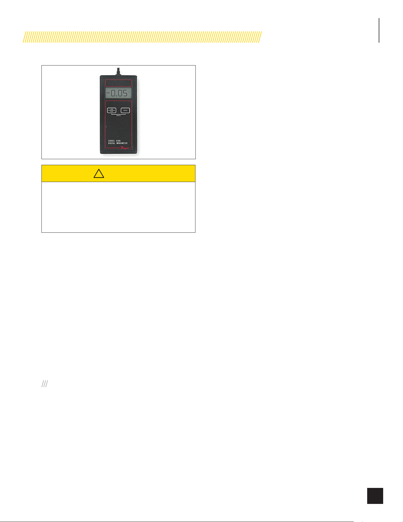
INSTALLATION
37
Part No. 101049
!
CAUTION
Remove the plug, install the Manometer. Open the
gas supply valve check to make sure the pressures
are within the specified values for NG or LPG. This is
always a good starting point for evaluations related to
poor performance.
After all appliances have been turn on, start the HSB. If the
Manometer stays within 5 -7 inches of water column for NG,
10 -12 inches of water column for LP, with full load applied to a
proper running HSB, the installation is good.
If the Manometer reading falls below the listed inches of water
column for either specific gas rating while the HSB engine is
starting or running. It may be an indication that the gas meter or
primary regulator is undersized.
If the Manometer reading stays within the specific gas rated
inches water column, but the HSB engine will not start, run
erratic, it may indicate insufficient fuel volume due to long fuel
supply pipe line, incorrect full pipe diameter. Recheck you initial
calculations to ensure where the problem might exist.
Champion HSB units have been run and tested at the factory.
They do not require any type of break-in period.
9. BATTERY REQUIREMENTS,
INSTALLATION & SERVICE
Battery sizing is a topic that is discussed and debated for a
number of reasons. The battery size, cold cranking amps (CCA),
starting cycle or deep cycle are all items for consideration. The
following will assist you to better understand the battery, the
codes and the purpose of the battery. It is extremely important
to follow all cautions and warnings per the battery manufacturer
concerning installation, service, maintenance and replacement
procedures.
Battery Council International (BCI) is an association of
battery industry companies whose members establish policy and
standards for the industry.
Battery Size is the physical dimensions of a battery. BCI assigns
letters and numbers for North American battery size types.
Cold Cranking Amps (CCA) is a rating that is used to define
the batteries ability to start an engine under low-temperature
conditions. BCI defines it as “the number of amps a lead-acid
battery at 0 degrees F can deliver for 30 seconds”.
Starting (cranking) Cycle Battery is designed to deliver large
bursts of power for a short time, as needed to start an engine.
Starting batteries are intended to have a low depth of discharge
on each use.
Deep Cycle Battery is designed to continuously provide power
for long periods of time (for example in a trolling motor, auxiliary
power for a RV or traction power for a golf cart or other battery
electric vehicle).
Two (2) 12 volt Group U1 batteries with a minimum of
350 CCA each. Battery size: 7
3/4
L × 5
3/16
W × 7
5/16
H inches
(196mm L × 131mm W × 185mm H). This is based on testing
in extreme cold and heat -22° F (-30° C) to 104 ° F (40° C).
Purchase batteries locally. Install positive cable first.
This is a 24 volt system. Most large trucks, buses and even some
RV’s use 24 Volt systems. While it is true that two batteries,
whether parallel (12 Volts), or in series (24 Volts) wired will
produce the same power, our 24 volt system makes it easier to
transfer power through higher voltages. With 24 Volts the engine
starter turns almost twice as fast as a 12 volt. This increased
starting speed enhances fuel delivery and combustion chamber
ignition in all weather conditions, especially in cold climate areas.
All 12 VDC batteries will lose a certain percentage of their charge
while in storage. It is important to test the battery voltage before
it is installed in the generator and taken to the job site. A fully
charged battery must test at 12.5 – 13.0 volts DC at 70 degrees F.
Also the correct batteries must have lug terminals to match
lug battery cables, for a bolt-together connection. All cautions
must be taken in accordance with the battery manufacturers
recommendations.
Check and confirm that the HSB on board controls are “ALL” in
the “OFF” position. This includes; circuit panel breaker, exercise
control and both LED controllers. Turn off utility power supply to
the ATS (automatic transfer switch), place ATS in “OFF” mode.
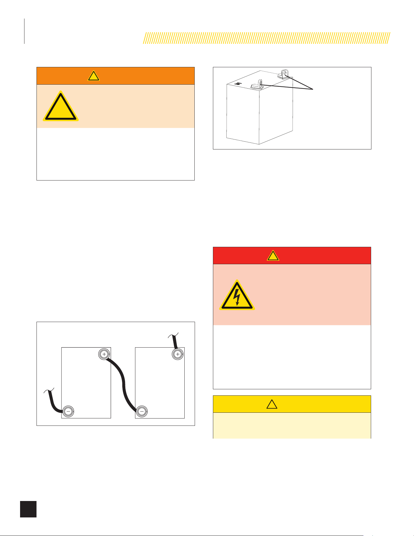
INSTALLATION
38
Part No. 101049
!
WARNING
!
The starting system is a 24-volt DC
system. The two 12-volt batteries
MUST be wired in series to achieve
the correct voltage.
Damage will result if the battery connections are
made in reverse, refer to owner manual or installation
manual for typical installation. Dielectric grease should
be applied on battery posts to aid in prevention of
corrosion. Cables supplied with the HSB.
1. Place the batteries into the built in battery tray.
2. Connect one of the black cables (included) from negative
(-) terminal of battery 1 to the positive (+) terminal of
battery 2.
3. Connect the red cable (included) from the positive (+)
terminal of battery 1 to the engine starter.
4. Connect the black cable (included) from negative (-)
terminal of battery 2 to the engine ground.
5. Install red battery post covers.
6. Dielectric grease should be applied on the battery posts to
aid in the prevention of corrosion.
7. Inspect, clean or re-grease battery connections every one
to two months.
To starter
To
ground
12
U1 Battery Post Style
This HSB is equipped with an automatic float type battery trickle
charger powered by utility power, to maintain full battery power
while in standby (non-running) mode. This trickle charger will not
recharge a fully discharged or defective battery. When the HSB
is running (during use), the engine provides power to the battery
charger, charging the batteries to maintain full battery power.
When doing any work on the batteries always make sure the
HSB, ATS and transfer switch from utility are in the “OFF” position
or sparking may occur at the battery posts as the cables are
attached and cause an explosion.
!
DANGER
Servicing of batteries are to
be performed or supervised
by personnel knowledgeable
of batteries and the required
precautions. Keep unauthorized
personnel away from batteries.
a. Always follow the battery manufacturer’s
directions.
b. When replacing batteries, use the same number
and the following type batteries: Two (2) 12 volt
Group U1 batteries with a minimum of 350 CCA
each (cold cranking amps).
!
CAUTION
A battery presents a rick of electrical shock and high
short circuit current.
INSTALLATION
39
Part No. 101049
!
CAUTION
The following precautions are to be observed when
working on batteries:
1. Remove watches, rings, or other metal objects,
2. Use tools with insulated handles,
3. Wear rubber gloves and boots,
4. Do not lay tools or metal parts on top of the
battery
5. Disconnect charging source prior to connecting
or disconnecting battery terminals,
6. Determine the battery is inadvertently grounded.
When inadvertently grounded, remove source
of ground. Contact with any part of a grounded
battery is capable of resulting in electrical
shock. The risk of such a shock is reduced when
such grounds are removed during installation
and maintenance (applicable to a generator not
having a grounded supply circuit.
!
CAUTION
Do not dispose of battery or batteries in a fire. The
battery is capable of exploding.
!
CAUTION
Do not open or mutilate the battery or batteries.
Released electrolyte has been known to be harmful to
the skin and eyes and can be toxic.
VENTED BATTERIES
The installation of the engine generator shall provide enough
ventilation to ensure that all gases generated by vented batteries
during charging, or caused by equipment malfunction are
removed.
!
CAUTION
The electrolyte is a diluted sulfuric acid that is harmful
to the skin and eyes. It is electrically conductive and
corrosive.
!
CAUTION
The following procedures are to be observed:
1. Wear full eye protection and protective clothing,
2. Where electrolyte contacts the skin, wash it
immediately with water,
3. Where electrolyte contacts the eyes, flush
thoroughly and immediately with water and seek
medical attention, and 40 Spilled electrolyte is to
be washed down with an acid neutralizing agent.
A common practice is to use a solution of one
pound (500 grams) bicarbonate of soda to one
gallon (4 liters) of water. The bicarbonate of soda
is to be added until the evidence of reaction
(foaming) has ceased. The resulting liquid is to
be flushed with water and the area dried.
!
CAUTION
Lead-acid batteries present a risk of fire because they
generate hydrogen gas.
The following procedures are to be followed:
1. DO NOT SMOKE when near batteries.
2. DO NOT cause flame or spark in battery area,
and
3. Discharge static electricity from body before
touching batteries by first touching a grounded
metal surface.
WIRE SIZING
All installations must comply with National, State and Local
codes. It is the responsibility of the installer to perform an
installation that will pass the final electrical inspection. Conductor
wire sizes must be adequate to handle the maximum current to
which they will be subjected. The installation must comply fully
with all applicable codes, standards and regulations.
All power cables must enter the enclosure through the knockouts
provided. If not using knockouts, conduit entry into the enclosure
must be at or below knockouts to maintain the Type 3R rating.
NEMA 3R enclosures are rated and tested for outside installation,
they are water proof enclosures and only come with knockouts
on the bottom side of the enclosure. If a NEMA 3R enclosure
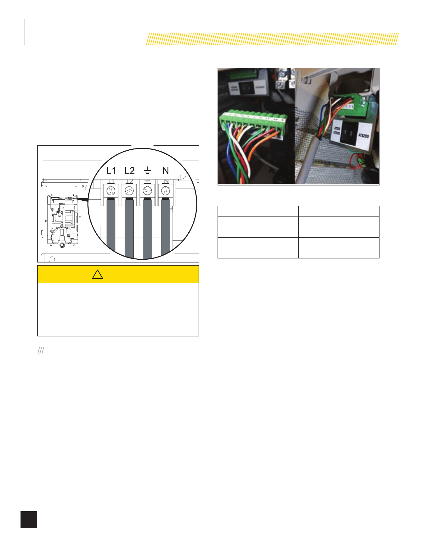
INSTALLATION
40
Part No. 101049
in used for an inside installation, a greenlee type punch will
be required to make a knockout(s) on the side or top of the
enclosure. Conduits should be arranged to provide separation
between the Utility Source and HSB Source supply conduits
inside the enclosure.
Conductor wires must be properly supported, of approved
insulated qualities, protected by approved conduit and of the
correct wire gauge size in accordance with all applicable codes.
!
CAUTION
Use a torque wrench to tighten conductors, being sure
not to overtighten, or damage to the switch base could
occur. If not tightened properly, a loose connection
would result, causing excess heat which could damage
the switch base.
INSTALLING COMMUNICATION WIRES
1. All communication circuit wires are color coded for easy
identification.
2. Route the multi-conductor wires (cable) from the HSB
generator (10 position connector) to the 12 position center
terminal block in the ATS. Strip the wires1/4 inch and
connect each wire to the terminal block in sequence. Note
that some of the terminal block positions are deliberately
left unused (TB2-4 and TBS-8).
TRANSFER SWITCH COMMUNICATION WIRE
Maximum Wire Length Recommended Wire Size
1 – 115 ft. (1 – 35m) No. 18 AWG
116 – 185 ft. (36 – 56m) No. 16 AWG
186 – 295 ft. (57 – 89m) No. 14 AWG
296 – 460 ft. (90 – 140m) No. 12 AWG
Utility Circuit and Generator Power Connections
Conductor sizes must be adequate to handle the maximum
current to which they will be subjected to, based on the 75
degrees C column of tables, charts, ect. used to size conductors.
The installation must comply fully with all applicable codes
standards and regulations.
IDENTIFY/SELECT STANDBY
CIRCUITS
IDENTIFY THE BASIC NEEDS
It is very important to understand what items the home owner
wants powered by the HSB during a utility failure. The selection
of these items will indicate which circuits will be selected for
connection to the ATS so that they are powered by the HSB.
Unforeseen power outages can last from minutes to days, so
it is important to focus circuit selections on those that power
household items that are deemed essential and within the output
capability of the HSB
An authorized or certified dealer or electrician can come to your
home and measure the loads with a clamp-on AMP meter which
would provide accurate load demands for each circuit tested.
INSTALLATION
41
Part No. 101049
Once you have identified the customer needs, you can
properly size the HSB by referring to the sizing guide provided
by Champion, www.championpowerequipment.com or call
Champion 1-877-338-0999.
Circuits must be protected by the same size breaker. For
example, a 15 amp 120 volt circuit in the ATS will replace a
15 amp 120 volt circuit in the main utility distribution panel.
When tied together or backed up, the breakers must be the same
size.
SURGE PROTECTION
!
CAUTION
Voltage fluctuation may impair the proper functioning
of sensitive electronic equipment.
Electronic devices, including computers and many programmable
appliances use components that are designed to operate within a
narrow voltage range and may be affected by momentary voltage
fluctuations. While there is no way to prevent voltage fluctuations,
you can take steps to protect sensitive electronic equipment.
1. Install UL1449, CSA-listed, plug-in surge suppressors
on the outlets feeding your sensitive equipment. Surge
suppressors come in single or multi-outlet styles. They’re
designed to protect against virtually all short-duration
voltage fluctuations.
HOUR METER & OVER VOLTAGE
PROTECTION
HOUR METER
The hour meter keeps track of all running time of the HSB. This
includes run time during a utility power outage and during the
weekly exercise cycle. This provides the owner with a record
of operating time which is useful in keeping track of scheduled
maintenance intervals. Refer to the scheduled maintenance chart
in your Owner’s Manual for specific maintenance.
The hour meter can’t be reset. The initial time registered on the
meter when first started up (installed) will reflect the factory test
time, this is a normal industry standard. The hour meter only
reflects hours, it does not reflect RPMs or any other function.
There are 2 pin connectors, both have positive locking
connections for correct orientation. Refer to wiring diagram in the
owner’s or installation manual of your specific model.
1 has a 3 point connector, top is B = Black wire (Gen-AC, L1),
center is not used, bottom connector is R = Red wire (L2).
The other is a 2 point connector, top is W = White (B+ on Engine
Relay Module), bottom is G = Green (B- on Engine Relay Module).
OVER VOLTAGE PROTECTION (OVP)
The OVP is a relay that protects the controls of the HSB from an
over voltage situation. By monitoring the voltage output from the
generator within pre-determined, factory set parameters, the
OVP can close off the path of voltage, should the voltage exceed
the limit. Should this occur the HSB system is protected from a
potential overload situation, turns off and shuts down the HSB.
There are 2 pin connectors, both have positive locking
connections for correct orientation. Refer to wiring diagram in the
owner’s or installation manual of your specific unit.
The square 4 pin connector, top left position, G = Green wire
(Ground), bottom left L/B = Blue/Black (Ignition coil), bottom right
is not used, top right R = Red wire (Battery).
The rectangle 3 pin connector, top position, R = RED wire (L2),
middle is not used, bottom is W = WHITE (Neutral).
EXERCISE LED
The GREEN LED will be flashing when the HSB is performing the
weekly exercise cycle. When the exercise period has completed,
the LED will stay lit and the HSB will resume standby monitoring.
SET EXERCISE TIME
To set the exercise time,
1. The Engine Control Module switch must be in the ATS
mode.
2. Decide on the desired day and time to exercise the HSB
generator.
3. Press the exercise switch to ON.
4. The HSB generator will start and run for 15 minutes and
then shut off.
5. The exercise time is now set.
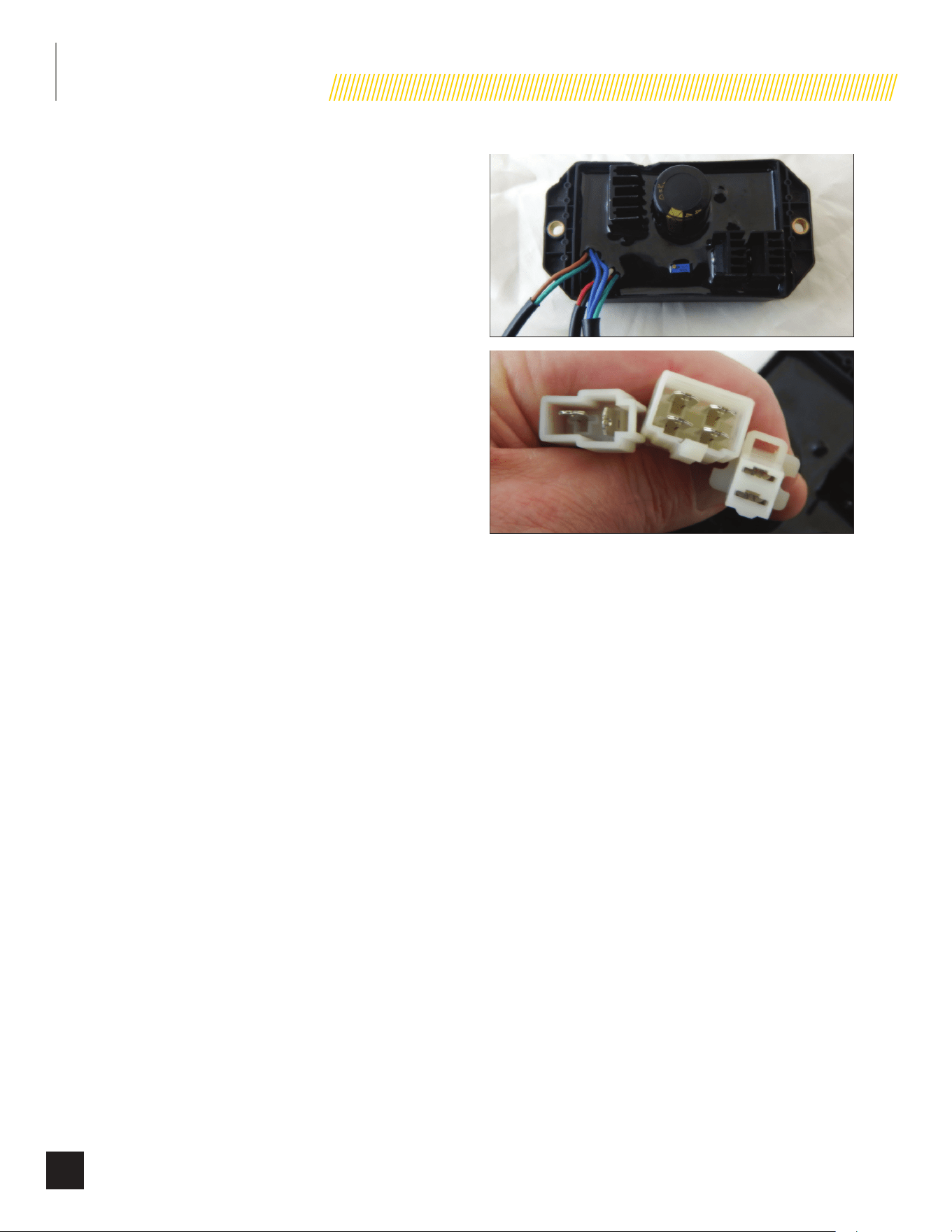
INSTALLATION
42
Part No. 101049
6. The HSB generator will begin the next exercise period
exactly 168 hours from when the exercise switch
was pressed to the ON position. The exercise switch
incorporates a built-in timer.
7. Load transfer from the HSB generator output will not occur
unless the utility power is lost.
The exercise time setting is specific to the day and time you set
it on site.
When the exerciser switch is in the OFF position, the exercise
function is disabled.
RESET OR CHANGE EXERCISE TIME
If you chose to change the current exercise time setting or
reset the time setting, choose the new day and time. Switch the
exercise switch to OFF and then to ON and it will begin the cycle
again.
EXERCISE TIME WILL HAVE TO BE RESET IF;
1. The battery was disconnected from the HSB generator.
2. The exercise switch was moved to the OFF position for
maintenance.
AVR = AUTOMATIC VOLTAGE
REGULATOR
The AVR is an electrical or electronic device that maintains the
voltage of a power source within predetermined limits. AVR is a
regulator that automatically keeps voltage within the prescribed
range required by the electrical equipment that will be provided
power by the HSB. The AVR uses solid-state semiconductor
devices to smooth out variations in the flow of current.
The AVR monitors the output voltage and controls the input
voltage to the exciter of the generator. By increasing or
decreasing the generator control voltage, the output voltage
of the generator increases or decreases accordingly. The AVR
calculates how much voltage has to be sent to exciter numerous
times a second, therefore stabilizing the output voltage to a
predetermined set point.
There are 3 connectors that come from the AVR. For reference
we have numbered them 1, 2, and 3 when viewed right to left.
Connector #1 (far left connector), has 2 leads. A RED lead (right)
that runs to the positive side of the brush assembly, and a BLACK
lead (left) that runs to the negative side of the brush assembly.
The brush assembly provides flow through of excitation current
to the rotating rotor. Brushes are made of long lasting material
that seldom wear out or fail. The contact points of the brush
assembly are with two slip rings attached to the rotor. These slip
rings can become tarnished or exhibit a glaze, which can create
a resistance to the flow of electricity. This can occur when the
HSB is not exercised or ran over long periods of storage.
Connector #2 (center), has 4 leads. The 2 leads on the right
side of the connector (top & bottom) are BLUE. They run to the
excitation windings on the stator. The 2 leads on the left side
of the connector (top & bottom) are GREEN (top) and WHITE
(bottom), they run to the sampling windings of the stator.
Connector #3 (far right), has 2 leads. The top lead is BROWN,
when connected it runs to pre-boost/magnetized pin #7 on the
Engine Controller Module. The bottom lead is GREEN and runs to
ground.
Slotted potentiometer is factory set to the correct voltage and
should not require adjustment.
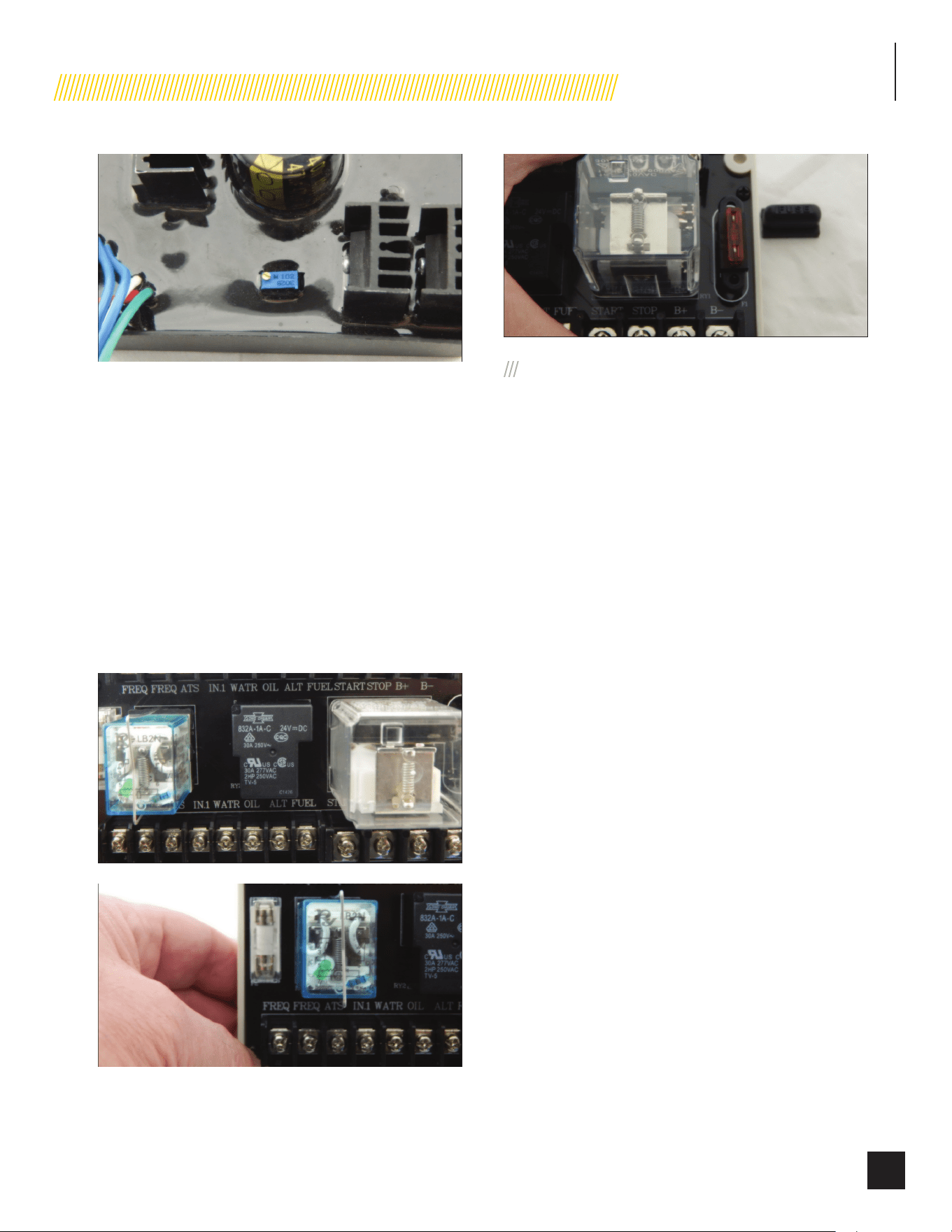
INSTALLATION
43
Part No. 101049
ENGINE RELAY MODULE
This module is the interface between the Engine Controller, ATS
Controller, alternator, hour meter and battery charger. It is the
interface for all on board communications in the HSB.
The module has two (2) fuses built into the board. On the left
side of the module there is a 250VAC 5A mini fuse protecting
the system from an over voltage between the alternator and the
relays.
The second fuse, is an automotive style fuse, 40A (Orange),
which protects the system from an excessive transfer voltage
output when the ATS relays transfer between Utility to Genset
and Genset to Utility modes.
TOP ROW
There are 12 wire land points in the top row, the connection
points are all the same size. The following are the wire land
points, function and wire color, this is viewed left to right.
1. Position #1 Frequency R (RED)
2. Position #2 Frequency B (BLACK)
3. Position #3 ATS O (ORANGE)
4. Position #4 Exercise O/B (ORANGE/BLACK)
5. Position #5 High Engine Br (BROWN)
Temp
6. Position #6 Low oil level/ Y (YELLOW)
pressure
7. Position #7 NOT CONNECTED EMPTY
8. Position #8 Fuel supply G/B (GREEN/BLACK)
valve
9. Position #9 Starter B/W (BLACK/WHITE)
10. Position #10 Stop L/B (BLUE/BLACK)
11. Position #11 B+ W (WHITE)
12. Position #12 B- G (GREEN)
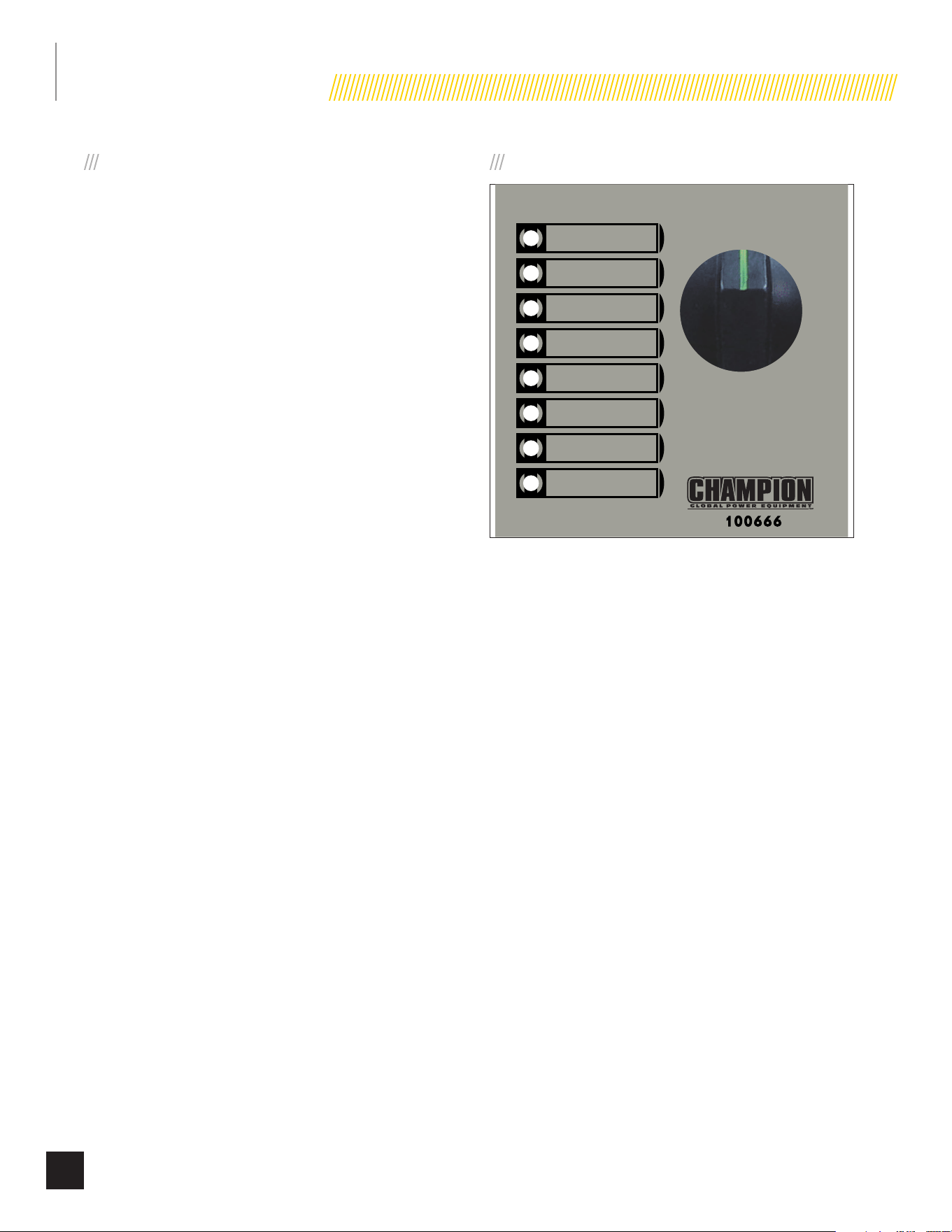
INSTALLATION
44
Part No. 101049
BOTTOM ROW
There are 12 wire land points in the bottom row, 8 are the same
size, the remaining 4 points are larger, viewed left to right. The
following are the wire land points, function and wire color, this is
viewed left to right.
1. Position #1 Frequency R (RED)
2. Position #2 Frequency B (BLACK)
3. Position #3 ATS O (ORANGE)
4. Position #4 Exercise O/B (ORANGE/BLACK)
5. Position #5 High Engine Br (BROWN)
Temp
6. Position #6 Low oil level/ Y (YELLOW)
pressure
7. Position #7 NOT CONNECTED EMPTY
8. Position #8 Fuel supply
valve G/B (GREEN/BLACK)
9. Position #9 Starter B/W (BLACK/WHITE)
10. Position #10 Stop L/B (BLUE/BLACK)
11. Position #11 B+ W (WHITE)
12. Position #12 B- G (GREEN)
ENGINE CONTROLLER
The Engine Controller Module is equipped to provide monitoring
and protection for the HSB. It applies a knob mode switch and
provides 3 operation modes; ATS (automatic), OFF and MANUAL.
Fault protection includes; over/under speed, high oil temperature,
low oil pressure, and over crank. It also displays low battery
voltage warning and indicates running and power status. The
output functions are executed by a set of traditional relays which
make it possible to support the HSB throughout standby mode
and operation.
MODE SWITCH
APAGADO
ARRÊT
OFF
Manual
Manuel
Manual
ATS
ATS
ATS
Hz over/under / Hz plus / sous
Hz Más / Menos
Run / Marche
Funcionar
Power / Alimentation
Potencia
High engine temperature
Surchauffe moteur
Alta temperatura del motor
Low oil / Huile basse
Baja de aceite
Over crank
Surdémarrage
Sobre manivela
Exercise / Exercice /
Ejercicio
Low battery /
Batterie faible
Batería baja
ATS POSITION
In this position the system is ready for full automatic operation.
1. Monitors constant utility power source voltage, if the
voltage is lost or is not consistent it will automatically start
and transfer to HSB.
2. When utility power is lost the Engine Control Module will
automatically disconnect the utility power from the home.
3. Command the HSB to start—allowing time for engine
warm-up and to bring generator up to maximum capacity.
4. Transfer load to HSB.
5. In this position the HSB will also perform its weekly
exercise cycle at the predetermined set time.
6. The HSB will attempt up to 5 starting sequences to
successfully start the HSB. If the HSB fails to start after
the 5th attempt the RED LED light, “Over Crank” will be
lit. The exterior fault code indicator LED on the backside
of the HSB will be activated and lit. Should this LED be lit,
the unit will not attempt to start or re-start. Follow reset
procedures contained in the manuals specific to your
model to clear or correct.
7. When the HSB is installed with an Automatic Transfer
Switch (ATS), and the ATS and Engine Control Module are
in the AUTO positions, the engine can crank and start at
any time. To prevent an automatic start of the HSB, both
the ATS Control Module and the Engine Control Module
must be placed in the OFF positions when all maintenance
or service are being performed on or around the unit.

INSTALLATION
45
Part No. 101049
OFF POSITION
This position closes and shuts down the engine signals. It
prevents the automatic operation of the generator. This position
is required when all maintenance or service are being performed
on or around the unit.
MANUAL POSITION
This position allows manual starting of the engine. Load transfer
from the HSB output does NOT occur unless the utility power
voltage is lost. NOTE: You cannot perform a load test of the
generator in the manual position.
EXERCISE LED
The GREEN LED will be flashing when the HSB is performing
the weekly exercise cycle. Refer to “Setting Exercise Time” to
establish the weekly exercise period. When the exercise period
is complete (15 minutes) the LED will stay lit and the HSB will
resume standby monitoring.
LOW BATTERY LED
The YELLOW LED will be lit if the battery voltage fell below 21.0
volts for at least one minute while the engine was running. If
the battery voltage rises above 21.1 volts, the LED will turn off.
Battery voltage is NOT monitored when the engine is cranking,
just when the engine is running. If the YELLOW LED comes on
it will not shut the HSB off, it will remain lit until the battery
condition meets the required output.
When the LED remains lit, the battery charging should be
checked and the condition of the batteries. Follow reset
procedures contained in the manuals specific to your model to
clear or correct.
HIGH ENGINE TEMP. LED
The RED LED will be lit if the engine operating temperature
exceeds the factory preset limits. If excessive operating
temperature is detected, the HSB will shut down and re-start will
be disabled. The RED LEDs on the module and enclosure exterior
are lit.
This failure could be the result of an excessive load or high
ambient temperatures. Should this fault occur do the following;
1. Open the enclosure doors to increase air flow throughout
the unit.
2. Check oil level, add oil if required.
3. Inspect the interior and exterior of the enclosure for debris,
leaves, ect., and remove them to increase air flow around
and inside the unit.
4. Once the engine temperature falls into the normal
operating range, generally 30 minutes, follow the reset
procedures in the manuals specific to your model to clear
and correct fault.
5. Close the enclosure doors and the unit is ready to run.
HZ OVER/UNDER SPEED LED
The RED LED will be lit if the engine was operating above or
below its preset speed limits. These limits are factory set to
protect the HSB and the circuits connected to the generator
output circuits. When this fault occurs, the HSB will shut down,
light the RED LED, shut down and re-start will be disabled. The
exterior fault code LED on the back of the HSB enclosure will be
activated and lit.
Appliances connected to the generator circuit could be damaged
from high generator output if the engine is allowed to operate
above the factory preset limits. If this failure occurs contact
Champion or your Authorized Champion Dealer. The RED LED will
remain lit until the failure has been corrected, the HSB will not
attempt to transfer or run.
LOW OIL LED
The RED LED will be lit when the engine oil level drops below
the safe operating level. When this fault is detected, the HSB
will shut down and re-start will be disabled. RED LEDs on the
module and enclosure exterior are lit.
Check the oil level. The oil level should be at the FULL mark, if
necessary, add oil. DO NOT overfill. Inspect the unit for a possible
oil leak, if a leak is discovered, contact Champion or your nearest
Authorized Champion Dealer. Follow the reset procedures
contained in the manuals specific to your model to clear and
correct.
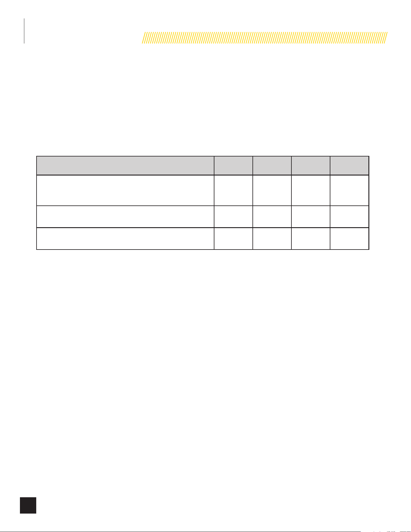
INSTALLATION
46
Part No. 101049
OVER CRANK LED
The RED LED will be lit if the engine does not start. This prevents the HSB from damaging itself or other related components. When the
fault is detected, the HSB will shut down and re-start will be disabled. RED icon on the controller module and exterior LED will be lit.
STARTER CRANK CYCLE TIMES - If the HSB fails to start, the “OVER CRANK” LED will flash on the Engine Control Module and a steady lit
exterior warning LED on the backside of the HSB. Below outlines the crank cycle differences depending on the mode selected. Please note
there is a 120 second lockout or rest period after the cycles for each mode listed to allow the starter to properly cool.
Follow the RESET FAULT CODE(S) instructions by placing the Engine Control Module in the OFF position to clear the fault. Regardless
of when you turn the control to OFF, you will need to allow the timer to count down to zero (0) before proceeding with another start
procedure. The lockout time remaining is not shown as there is no screen.
MODE
ON
(seconds)
OFF
(seconds)
CYCLES
LOCKOUT
(seconds)
ATS
The HSB is in the ready position. The Engine Control Module must be in
the ATS mode (AUTO mode) in order to exercise.
9 10 5 120
MANUAL
The HSB will start in MANUAL mode.
10 10 2 120
EXERCISE
The HSB is connected to a Champion Automatic Transfer Switch.
9 10 5 120
This failure could be the result of insufficient fuel supply. Check the in-line fuel shut off valves and make sure they are in the ON/OPEN
position. Position them in the correct position, follow the RESET FAULT CODE(S) instructions to clear the fault after service. If they are in
the correct position and the HSB shows a fault light again, it’s recommended to perform a Manometer pressure check by an Authorized
Champion Dealer or installer. This will make sure the correct amount of fuel is being delivered to the HSB when it starts.
Insufficient battery output could result in poor cranking cycles, not permitting the engine starter to reach optimum starting RPM to start
the engine. If this occurs, the individual battery voltages must be checked to determine if the batteries are properly charged or if they
have failed. It is extremely important to follow all the cautions and warnings per the battery manufacturer concerning installation, service,
maintenance and replacement procedures.
RUN LED
The GREEN LED will be lit if the engine is running and is only lit when the engine is running.
POWER LED
The GREEN LED will be lit, indicating the batteries are installed correctly in series providing the necessary 24VDC power and that loads
can be applied or transferred. If the battery charger is wired correctly, this LED will also be lit even without batteries installed.
LED INDICATORS
In all cases when the LED is GREEN, this is an indicator that the HSB is performing properly.
In all cases when the LED is RED, this is an indicator that the HSB has registered a fault and must be corrected. Only the “LOW BATTERY
LED” will not latch out or shut down the HSB. ALL other RED LED faults will latch out, shut down, disable starting and light the RED LEDs
on the Engine Control Module and the exterior fault code LED on the backside of the HSB.
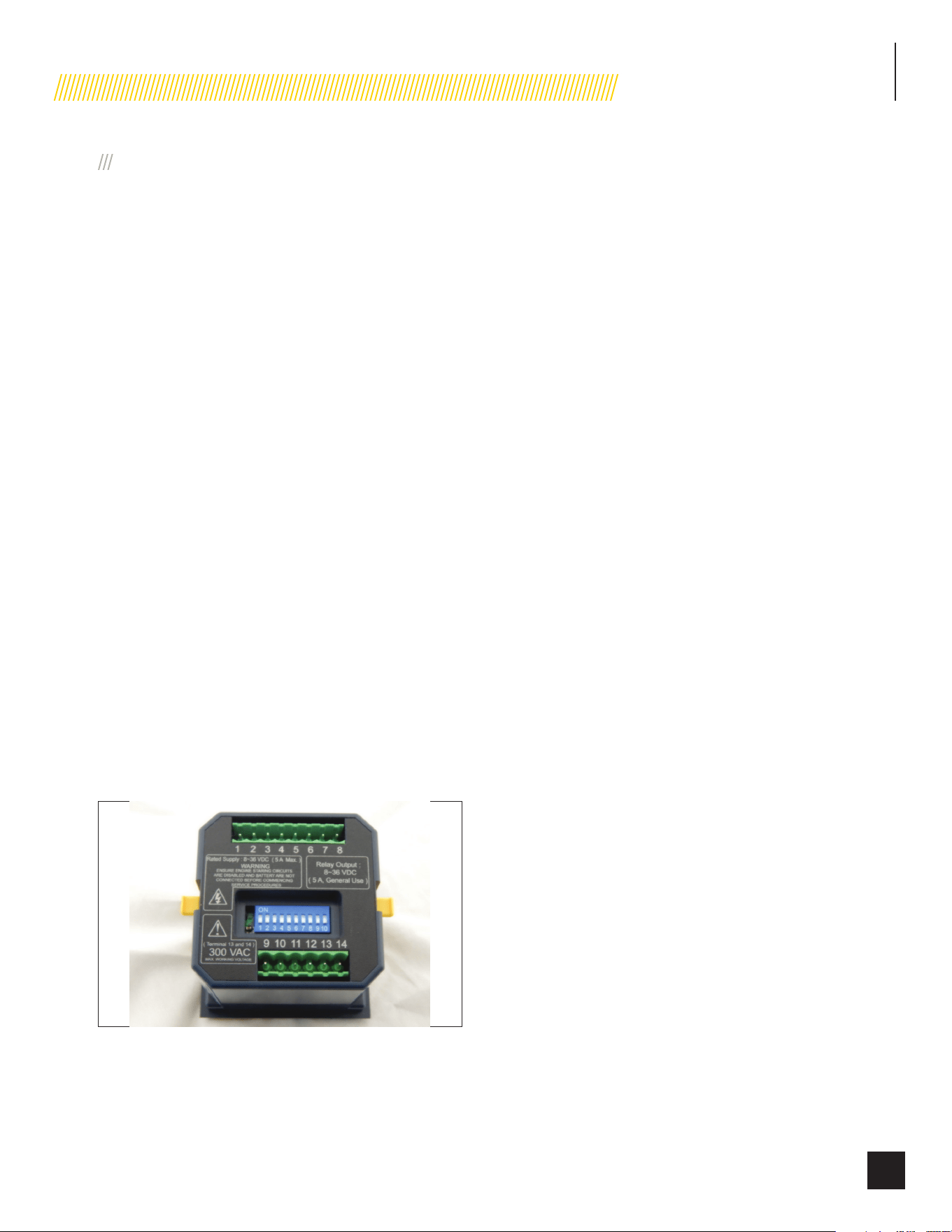
INSTALLATION
47
Part No. 101049
PIN LOCATIONS
(On backside of the controller)
The pins relate to a function of the Engine Controller module.
These functions control the operation of the HSB and ATS. The
ECM continually monitors the Utility source power 24/7. There
only 14 pin locations. Remember the LEDs on the front side of
the module are only indicators of a run (GREEN) or fault (Red).
These are the designated pin locations, function and wire colors
for reference;
1. Pin 1 B+ W(White)
2. Pin 2 B- G (Green)
3. Pin 3 Motor start signal B/W (Black/White)
4. Pin 4 Fuel valve G/B (Green/Black)
5. Pin 5 Drives all fault lights L (Blue)
6. Pin 6 Ground/stop L/B (Blue/Black)
7. Pin 7 Signal to alternator R/B (Red/Black)
8. Pin 8 Not Connected
9. Pin 9 Low Oil Level/ Y (Yellow)
Pressure
10. Pin 10 Engine High Temp Br (Brown)
11. Pin 11 Exercise O/B (Orange/Black)
12. Pin 12 Signal to ATS O (Orange)
13. Pin 13 Frequency Over/ B (Black)
Under
14. Pin 14 Frequency Over/ R (Red)
Under
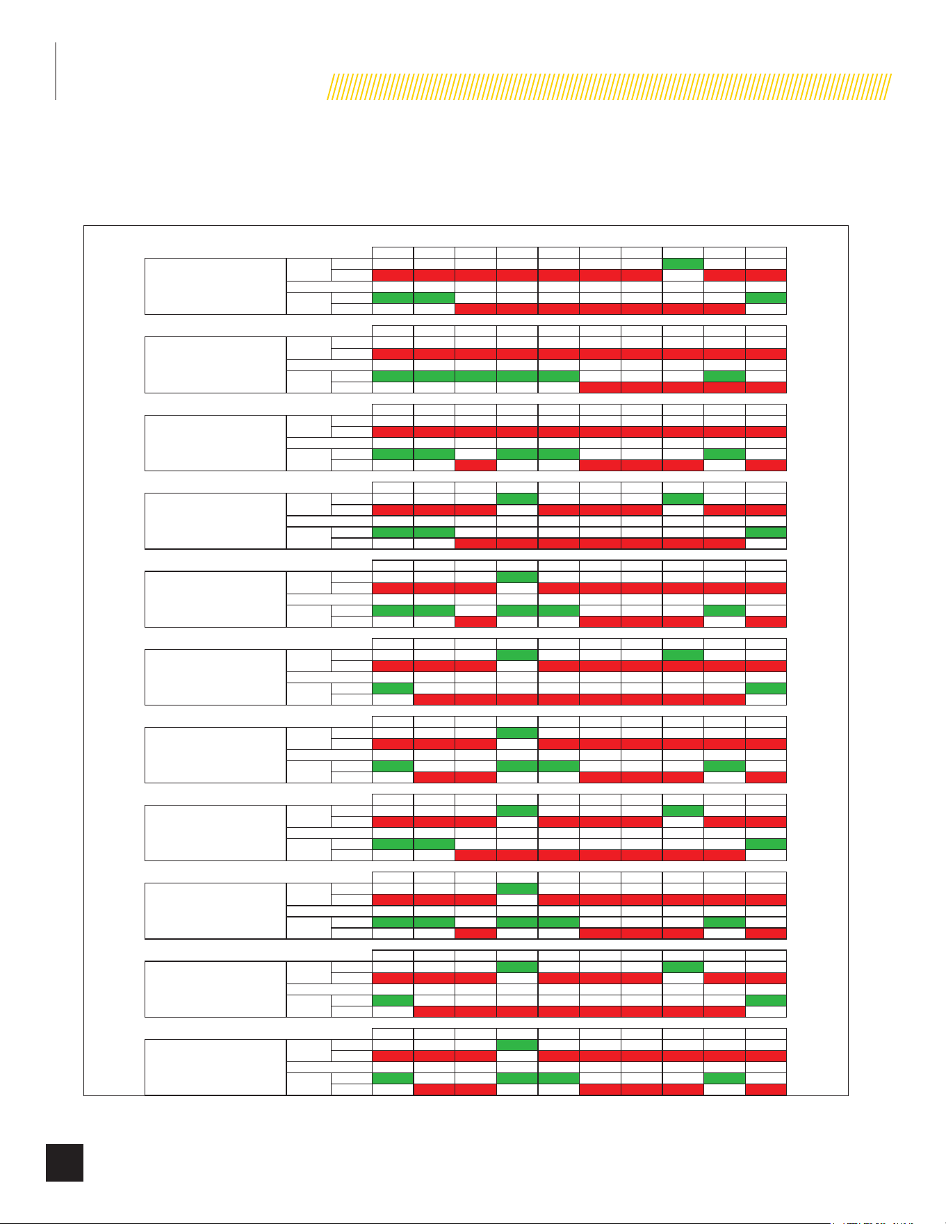
INSTALLATION
48
Part No. 101049
DIP SWITCHES ON THE BACK SIDE OF THE CONTROL MODULES IN BETWEEN THE 2 ROWS OF PIN CONNECTORS
The DIP Switches assist the ECM and ATS Control Module by setting parameters of control such as delays of time or intervals for signals.
There are only 10 DIP switches. These are the designated “ON” or “OFF” position settings for the DIP switches (factory pre-set);
DIP SWITCH
1 2 3 4 5 6 7 8 9 10
ON
OFF
1 2 3 4 5 6 7 8 9 10
ON
OFF
1 2 3 4 5 6 7 8 9 10
ON
OFF
1 2 3 4 5 6 7 8 9 10
ON
OFF
1 2 3 4 5 6 7 8 9 10
ON
OFF
1 2 3 4 5 6 7 8 9 10
ON
OFF
1 2 3 4 5 6 7 8 9 10
ON
OFF
1 2 3 4 5 6 7 8 9 10
ON
OFF
1 2 3 4 5 6 7 8 9 10
ON
OFF
1 2 3 4 5 6 7 8 9 10
ON
OFF
1 2 3 4 5 6 7 8 9 10
ON
OFF
1 2 3 4 5 6 7 8 9 10
ON
OFF
1 2 3 4 5 6 7 8 9 10
ON
OFF
1 2 3 4 5 6 7 8 9 10
ON
OFF
1 2 3 4 5 6 7 8 9 10
ON
OFF
1 2 3 4 5 6 7 8 9 10
ON
OFF
1 2 3 4 5 6 7 8 9 10
ON
OFF
1 2 3 4 5 6 7 8 9 10
ON
OFF
1 2 3 4 5 6 7 8 9 10
ON
OFF
1 2 3 4 5 6 7 8 9 10
ON
OFF
1 2 3 4 5 6 7 8 9 10
ON
OFF
1 2 3 4 5 6 7 8 9 10
ON
OFF
1
1
0
0
0
0
1
1
9
9
9
9
50A/100A
S
S
e
e
r
r
i
i
a
a
l
l
N
N
u
u
m
m
b
b
e
e
r
r
<18DEC2201761
1
1
0
0
0
0
6
6
6
6
6
6
1
1
0
0
0
0
6
6
6
6
7
7
1
1
0
0
0
0
2
2
3
3
7
7
200A
Serial Number <
18NOV2301385
1
1
0
0
0
0
6
6
6
6
6
6
1
1
0
0
0
0
6
6
6
6
7
7
1
1
0
0
0
0
1
1
3
3
6
6
200A
Serial Number <18DEC1900001
1
1
0
0
0
0
6
6
6
6
6
6
1
1
0
0
0
0
6
6
6
6
7
7
1
1
0
0
0
0
1
1
3
3
6
6
200A
Serial Number 18DEC1900001 +
1
1
0
0
0
0
6
6
6
6
6
6
1
1
0
0
0
0
6
6
6
6
7
7
1
1
0
0
0
0
1
1
3
3
6
6
50A/100A
Serial Number <18DEC1900001
1
1
0
0
0
0
6
6
6
6
6
6
1
1
0
0
0
0
6
6
6
6
7
7
1
1
0
0
0
0
1
1
3
3
6
6
50A/100A
Serial Number 18DEC1900001 +
1
1
0
0
0
0
2
2
3
3
7
7
200A
Serial Number 18NOV2301385+
1
1
0
0
0
0
6
6
6
6
6
6
1
1
0
0
0
0
6
6
6
6
7
7
1
1
0
0
0
0
2
2
3
3
7
7
50A/100A
Serial Number <
18NOV2301385
1
1
0
0
0
0
6
6
6
6
6
6
1
1
0
0
0
0
6
6
6
6
7
7
1
1
0
0
0
0
2
2
3
3
7
7
50A/100A
Serial Number 18NOV2301385 +
1
1
0
0
0
0
6
6
6
6
6
6
1
1
0
0
0
0
6
6
6
6
7
7
1
1
0
0
0
0
6
6
6
6
6
6
1
1
0
0
0
0
6
6
6
6
7
7
1
1
0
0
0
0
6
6
6
6
6
6
1
1
0
0
0
0
6
6
6
6
7
7
1
1
0
0
0
0
1
1
9
9
9
9
50A/100A
Serial Number 18DEC2201761 +
1
1
0
0
0
0
1
1
9
9
9
9
50A/100A
Serial Number Future TBD
1
1
0
0
0
0
6
6
6
6
6
6
1
1
0
0
0
0
6
6
6
6
7
7
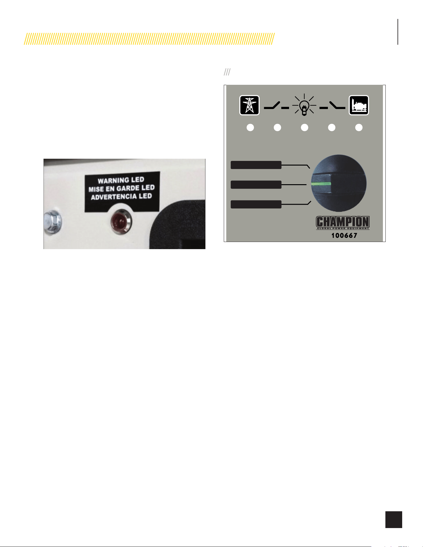
INSTALLATION
49
Part No. 101049
EXTERIOR WARNING LED
The exterior of the generator enclosure includes a Warning LED
that illuminates RED when a fault has occurred
The Warning LED provides a visual indicator to homeowners
and service technicians that a fault has occurred, and service is
needed.
The Warning LED is located on the back-exterior panel mounted
next to the air intake louver.
ATS CONTROL MODULE
The ATS Control Module contains the TEST/AUTO/OFF switch
and LEDs that indicate the type/source of power delivery into
the home. The module will reflect Utility power source when the
utility power source is coming into the home. The 3 LEDs on the
left will be lit (UTILITY, ATS active, LOAD, view left to right).
The module will reflect GENSET power when the Generator is
the source of power being delivered into the home. The 3 LEDs
on the right will be lit (LOAD, ATS active, GENSET, view center to
right).
This is a two (2) wire start system. The control of HSB operation
and ATS operation are done through the controls in the HSB.
This is done by a wire connection to the HSB and then a wire
correction from the HSB to the ATS. All system communications,
monitoring of the Utility power source and control of the HSB are
coordinated through the control modules on the HSB. A one (1)
wire start is a system in which the communications, monitoring
and control of power source is done through the ATS.
TEST/AUTO/OFF SWITCH
AUTO / AUTO / AUTOMÁTICO
OFF / ARRÊT / APAGADO
TEST / ESSAI / PRUEBA
UTILIDAD
UTILITÉ
UTILITY
CARGA
CHARGER
LOAD
GENSET
GENSET
GENSET
TEST
This position allows verification that the HSB power delivery
circuit is functional. With the switch in the TEST position, the
engine will start and the ATS will transfer from Utility power to the
HSB power. Safety procedures should be followed.
Prior to placing the ATS Control Module in the “TEST” position,
the UTILITY, ATS active and LOAD LEDs will be lit.
Placing the ATS Control Module in the “TEST” position will
command the HSB to start and to transfer the power source
from utility power to the HSB power. The LOAD, ATS active and
GENSET LEDs will be lit (view center to right).
AUTO
This position allows automatic delivery of power from the HSB
when there is a Utility power source outage. With the switch in
the AUTO position and the HSB not running (in standby mode),
the UTILITY, ATS active and LOAD LEDs will be lit (view left to
right), this indicates the household is using Utility power source.
This position is the standby ready position.
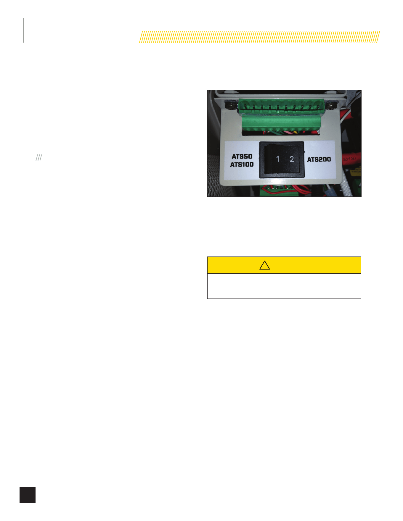
INSTALLATION
50
Part No. 101049
OFF
This position will not allow any power to be delivered or
transferred to the ATS or the household when the engine (HSB)
is running.
The UTILITY, ATS active and LOAD LEDs will remain lit, indicating
the Utility power source is providing power to the household. If
the Utility power source is turned off (main line breaker is turned
“OFF”) or if a Utility power source failure occurs, NO LEDs will be
lit if the ATS Control Module is in the “OFF” position.
PIN LOCATIONS
(On the backside of ATS Control Module)
The pin locations are relate to the interaction/communication
between the Engine Controller, the ATS Control Module and
the ATS. There are only 16 pin locations, two rows of 8. When
installing the pin connection plugs, the top plug is wired RED,
GREEN, RED, viewed left to right. This will eliminate incorrect
installation. These are the designated pin locations, function and
wire colors for reference;
1. Pin 1 B+ R (Red) top row (viewed
left to right)
2. Pin 2 B- G (Green) top row
3. Pin 3 Utility close R (Red) top row
4. Pin 4 Utility close B/W (Black/White)
top row
5. Pin 5 Gen-set close L (Blue) top row
6. Pin 6 Gen-set close R (Red) top row
7. Pin 7 B- G (Green) top row
8. Pin 8 Start ATS O (Orange) top row
9. Pin 9 Gen-set C.B. G/B (Green/Black)
10. Pin 10 Utility C.B. Y (Yellow)
11. Pin 11 Utility AC Detect Pu (Purple)
12. Pin 12 Utility AC Detect O (Orange)
13. Pin 13 Load AC Detect P (Pink)
14. Pin 14 Load AC Detect Br (Brown)
15. Pin 15 Gen AC Detect B (Black)
16. Pin 16 Gen AC Detect R (Red)
ATS SELECT SWITCH
(does not apply to model 100199.)
This unit may be wired to several models of ATS (automatic
transfer switch). The selector switch is located onboard the
generator near the ATS signal wire connector. Select position “1”
if you are connecting to an ATS50 or ATS100 and select position
“2” if you are connecting to a service entry demand control ATS
(up to 200A).
!
CAUTION
Failure to set this switch to the matching ATS installed
can result in damage to both ATS and HSB.
BATTERY CHARGER
This automatic battery charger is an intelligent module which
maintains lead acid batteries at a full charge, when the HSB has
been properly installed. Continual monitoring and maintenance
will promote long battery life. In accordance with the principle of
high efficiency, at Full Load, >85% of efficiency is achieved. This
charger is a maintenance battery charger. If the battery voltage
falls below 6V, the charger will not re-change the batteries.
To properly maintain battery efficiency you must follow the
battery manufacturers; safety instructions, warnings and proper
maintenance procedures.
Feature benefits include; reverse polarity protection, short
circuit protection, overload protection, over voltage, over current,
floating charging system, constant voltage output and a rugged
design for industrial environments. The charger is also equipped
with a manual reset which is located on the far right side of the
wire land points. This charger is for lead acid batteries only. All
adjustments are preset at the factory.
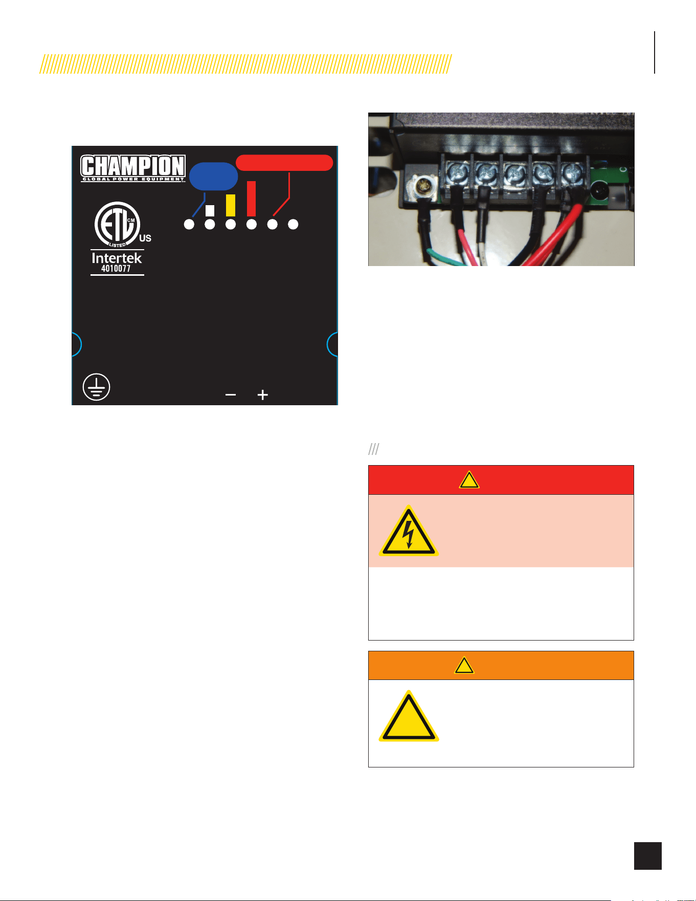
INSTALLATION
51
Part No. 101049
The automatic battery charger has five (5) built in LEDs that
display the following, view left to right;
NO CHARGE / PAS DE CHARGE /
SIN CARGA
AUTOMATIC BATTERY CHARGER /
CHARGE AUTOMATIQUE DE BATTERIE /
CARGADOR DE BATERÍA AUTOMÁTICO
Output: 24 Vdc 1.6 A
Producción: 24 V C.C. 1,6 A
Sortie : 24 V c.c. 1,6 A
Power: 80-125 Vac 1.0 A 50 / 60 Hz
Potencia: 80 - 125 V C.A. 1,0 A 50 / 60 Hz
Alimentation : 80-125 V c.a. 1,0 A 50 / 60 Hz
L N ADJ
E. O.
V
POWER / ALIMENTATION /
POTENCIA
OUTPUT / SORTIE /
PRODUCCIÓN
POWER
ALIMENTATION
POTENCIA
Conforms to UL
Std. 1236
RECOGNIZED
COMPONENT
For use with lead acid (LA/SLA), AGM, or Gel batteries. Not for use with Lithium-ion batteries.
Pour une utilisation avec des batteries au plomb-acide (LA/SLA), AGM ou gel. Ne pas utiliser
avec des batteries au lithium-ion.
Para uso con baterías de plomo ácido (LA/SLA), AGM o gel. No para uso con las baterías de iones de litio.
K 109 485 REFLEX BLUE
ColorsAPN 2484-L-PR
Rev C
Size 76 x 75 mm
Artwork Notes
2mm safe margin;
to be printed on
White
substrate.
Revision Changes
B: Deleted the model and added the chemistry notes
C: Added the hole for E.O. --20250311
This artwork belongs to Champion Power Equipment. The contents are confidential and privileged and shall not be disclosed to or used by or for
outside parties without the explicit consent of Champion Power Equipment.
1. Power – Lit to indicate the battery is fully charged.
2. Small Bar – Lit to indicate the battery is receiving a trickle
charge.
3. Middle Bar – Lit to indicate current output is near 50%.
4. Large Bar – Lit to indicate the charger is operating above
50% capacity.
5. NO CHARGE – Lit to indicate a battery charging problem.
If this LED is lit, the LED on the Engine Controller module,
“LOW BATTERY” will also be lit.
The battery(s) might be discharged to a level that is too low to re-
charged with this charger (battery voltage below 6V). If this is the
case, the batteries will need to be charged individually. Remove
all battery cables from the batteries and follow the battery
manufacturers’ instructions on properly servicing/charging the
batteries.
Be careful to avoid corrosion on the battery post(s). Corrosion
can have the effect of creating an insulation between the post(s)
and the cable(s), this will severely affect the performance of the
battery. Follow battery manufacturers’ instructions on proper
maintenance, service or replacement. The correct wire lands are
read left to right, 6 land points;
1. Wire land #1 Ground G (GREEN)
2. Wire land #2 L1 P (PINK)
3. Wire land #3 N W (WHITE)
4. Wire land #4 NOT CONNECTED EMPTY
5. Wire land #5 B- B (BLACK)
6. Wire land #6 B+ R (RED)
HSB TEST
VOLTAGE CHECKS – NO LOAD
!
DANGER
Proceed with caution. Once the
Utility Power is turned ON, the ATS is
now electrically hot. The feeder lines
and terminals are now live.
Contact with these connections will result in extremely
hazardous and possibly fatal electrical shock. Use the
correct procedures as described in national electrical
codes.
!
WARNING
!
The manufacturer recommends
that a licensed electrician or an
individual with complete knowledge
of electricity perform these
procedures.
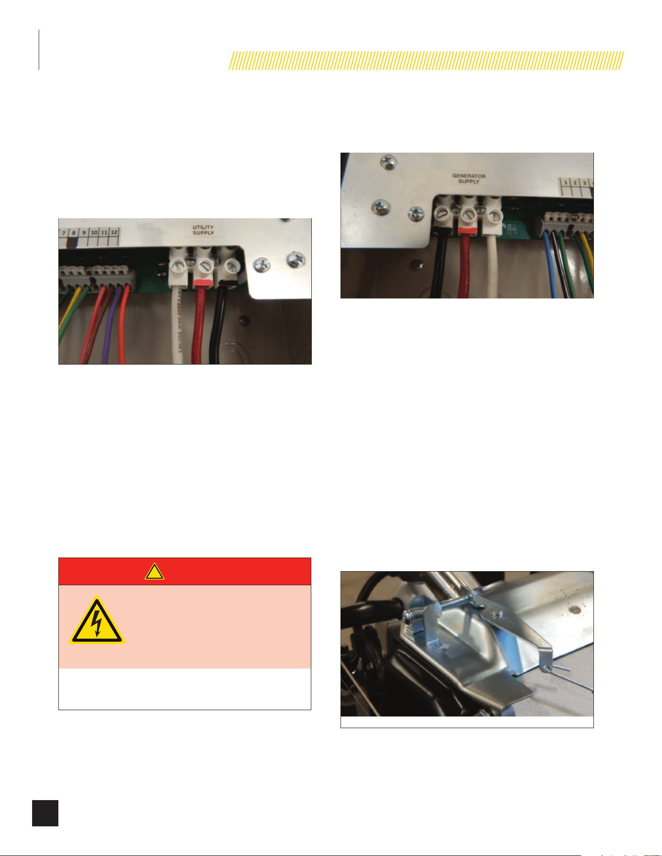
INSTALLATION
52
Part No. 101049
1. With the Engine Control Module and ATS Module both in
the OFF position.
2. Turn ON the utility power supply to the ATS.
3. With an AC voltmeter, check for the correct voltage.
Single-phase utility power supply. Measure across the
UTILITY SUPPLY ATS terminal lugs L1 and L2. Also check
L1 to NEUTRAL and L2 to NEUTRAL.
4. The utility supply voltage should be correct and compatible
with the ATS ratings.
5. Turn OFF the utility power supply to the ATS.
6. The Control Panel MAIN CIRCUIT BREAKER must be in the
OFF position.
7. Set the ATS module in the test mode.
8. Set the Engine Control Module in the MANUAL mode. The
HSB will crank and start. Let the HSB warm up at no load
for 5 minutes to stabilize performance.
9. Set the Control Panel MAIN CIRCUIT BREAKER in the ON
position.
!
DANGER
Proceed with caution. HSB generator
output voltage is now being delivered
to the ATS and is electrically hot. The
feeder lines and terminals are now
live.
Contact with these connections will result in extremely
hazardous and possibly fatal electrical shock
10. With an AC voltmeter, check the correct voltage. Single-
phase generator supply.
11. Measure across GENERATOR SUPPLY ATS lugs L1 and L2.
Also check L1 to NEUTRAL and L2 to NEUTRAL. These are
factory pre-set limits.
Frequency 63 Hertz
Terminals L1 to L2 230 VAC
Terminals L1 to NEUTRAL 115 VAC
Terminals L2 to NEUTRAL 115 VAC
12. Set the HSB generator MAIN CIRCUIT BREAKER to its OFF
position.
13. Set the Engine Control Module and ATS Module to the OFF
position. This will shut off the HSB
Do NOT move forward until the HSB generator AC output voltage
and frequency are correct and within the stated limits.
1. If the no-load voltage is correct but no-load frequency is
incorrect, the engine governed speed requires adjustment.
Locate the governor arm bolt, turn the bolt clockwise to
increase RPM, counter clockwise to decrease RPM. No-
load RPM should be set at 3,780 RPM. The adjustments
should be made in ¼ turn increments. No-load Hertz
should read 63 Hertz.
Single Cylinder Frequency Adjustment
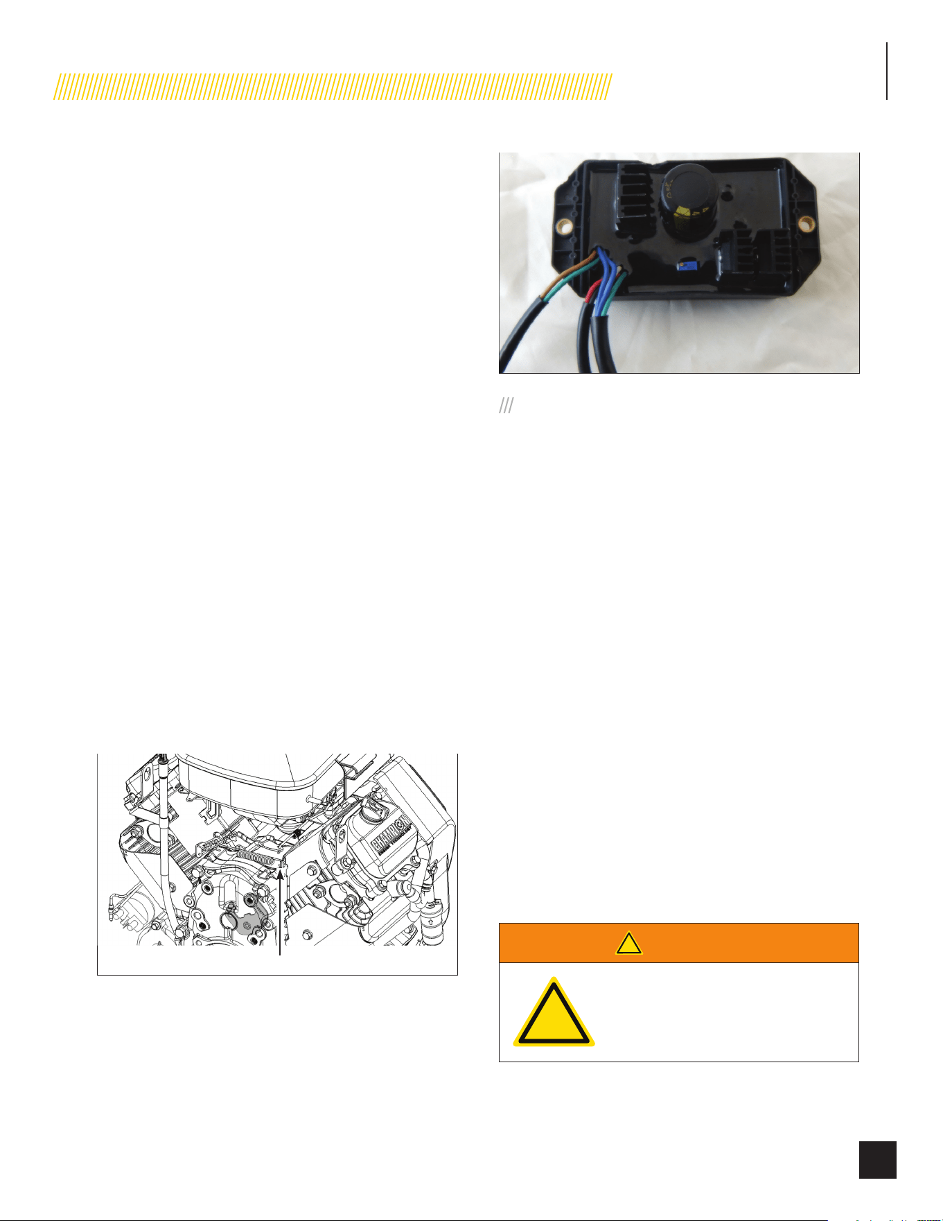
INSTALLATION
53
Part No. 101049
2. If no-load frequency is correct but voltage is not, the
voltage regulator (AVR) may require adjustment. Remove
the back electrical/fuel access panel. Locate the voltage
regulator (AVR) on the right inside wall. The AVR has a
slotted potentiometer for adjustment. With the frequency
set at 63 Hertz, slowly turn the slotted potentiometer clock
wise until voltage reads 230.
TWIN CYLINDER FREQUENCY
ADJUSTMENT
Do NOT move forward until the HSB generator AC output voltage
and frequency are correct and within the stated limits.
1. If the no-load voltage is correct but no-load frequency is
incorrect, the engine governed speed requires adjustment.
a. Engine speed is normally set to 3750 RPM (62.5 HZ)
high speed no load (HSNL)
b. Set engine speed with no electrical load on the
generator
c. Use long needle nose pliers, or a long screw driver, to
bend the spring anchor on the fixed speed controls.
i. To increase engine speed HSNL bend the spring
anchor tang on the fixed speed controls away from
the governor lever to increase spring tension.
ii. To decrease engine speed HSNL bend the spring
anchor tang on the fixed speed controls toward the
governor lever to decrease spring tension.
Bend spring anchor tang to adjust engine speed
HSB TESTS UNDER LOAD
During this test you DO NOT need to turn off any circuit
breakers in the Utility Main Distribution Panel, HSB Control
Panel or the ATS.
This procedure will verify load Voltage and frequency output.
Prior to starting the test you can place a Manometer in line to
check fuel flow when the HSB is under complete load.
1. Set the Engine Control Module in the ATS position.
2. Set the ATS Control Module in the TEST position.
3. With the switch in the TEST position, the engine will start
and the ATS will transfer.
4. The GENSET LED, ATS LED (middle LED) and the LOAD
LED will be lit, indicating the HSB generator power delivery
circuit is functional. The standby circuits from the ATS to
the Utility Main Distribution Panel are now powered by the
HSB and not the Utility.
All other electrical circuits in the home are powered by Utility
power and remain active during this test procedure. This test
provides HSB power to the designated standby circuits as it
would during a Utility power outage.
5. During this simulation test, all standby circuits will provide
full rated wattage/amperage capacity demands to the
HSB. DO NOT OVERLOAD.
!
WARNING
!
The manufacturer recommends
that a licensed electrician or an
individual with complete knowledge
of electricity perform these tests.

INSTALLATION
54
Part No. 101049
6. With rated load applied, check voltage and frequency
across ATS GENERATOR SUPPLY terminals L1 and L2.
Voltage should be greater than 216 Volts.
7. Frequency should be greater than 57 Hertz.
8. Verify that the gas pressure remains within the acceptable
parameters as listed in the manual, provided that you
placed a Manometer in line prior to starting this test.
9. Let the HSB run under load for at least 30 minutes. With
the unit running listen for unusual noises, inspect for
vibrations or other unusual items that might reflect a
problem.
10. When the test process is completed, switch the ATS
Control Module to the ATS position. The ATS will transfer
back to UTILITY SUPPLY, this will power all circuits of the
home.
11. The HSB will run through a cool down cycle, shut down
and return to standby mode.
The test is now complete and the system is in standby mode.
CHECKING AUTOMATIC
OPERATION
To check the HSB system for proper automatic operation,
proceed as follows:
1. Ensure the HSB is set in the OFF positions on both the
Engine Control Module and the ATS Module.
2. Install front cover of the ATS.
3. Return the Engine Control Module and the ATS Module
to their ATS positions. The HSB system is now ready for
automatic operation.
4. Turn OFF the Utility Main Circuit Breaker.
5. The engine should crank and start when the utility power
source is turned OFF.
6. After starting, the ATS should connect load circuits to the
GENERATOR SUPPLY. Let the HSB system operate through
its entire automatic sequence of operation.
7. Once the HSB system has run through its automatic
sequence of operation. Turn on the Utility Main Circuit
Breaker. The ATS should automatically transfer from
GENERATOR SUPPLY to UTILITY SUPPLY.
8. The HSB will run through a cool down cycle, shut off and
be in standby ready mode.
9. This check is now complete.
CUSTOMER FAMILIARIZATION
SUMMARY
It’s important to educate the home owner on proper
maintenance, operation and service call procedures. A properly
educated home owner can reduce unnecessary service trips and
phone calls.
Ensure that the installation of the HSB and ATS has been
correctly performed as outlined by the manufacturer and that it
meets all applicable codes.
Test and confirm proper operation of the HSB and ATS system as
outlined in the appropriate installation and owner’s manuals.
Educate the home owner on the location and operation of;
1. Full flow shutoff valve
2. Automatic operation of the HSB system
3. Engine Control Module and LED indicators
4. ATS Module and LED indicators
5. Battery Charger and LED indicators
6. Exterior fault code indicator LED on the backside of the
HSB
7. ATS operation
8. Exercise scheduled time of operation
9. Scheduled Maintenance
10. Fill out and provide the customer a copy of the HSB,
ATS model & serial number reference. This information
is extremely important for part purchases and service
information, these numbers are specific to each HSB and
ATS.
11. Fill out and provide the customer a copy of the ATS back-
up circuits.
12. Fill out the Circuit Label inside the ATS.
It’s always a good business practice to place business cards in
the Owner’s and Installation manuals and place dealer stickers
on the HSB and ATS for the customer’s reference.

INSTALLATION
55
Part No. 101049
NOTICE
By law it is required in many states to have a Carbon
Monoxide (CO) detector in operating condition in your
home. Carbon Monoxide detector(s) must be installed
and maintained indoors according to the manufacturer’s
instructions. A CO monitor is an electric device that detects
hazardous levels of CO. When there is a buildup of CO, the
monitor will alert the occupants by flashing a visual light
indicator and an audible alarm. Smoke alarms cannot detect
CO gas.
CO gas is odorless, colorless and tasteless and is unlikely to
be noticed until a person is overcome. Standby generators emit
carbon monoxide (CO) gas in the engine exhaust.
AUTOMATIC TRANSFER SWITCH
(ATS)
Refer to the Reliance instruction guide enclosed with each unit
for information related to installation, operation, service, trouble
shooting and warranty (Champion part number 101271).
The most reliable and convenient method to transfer power
is with an automatic transfer switch (ATS). The ATS will
automatically disconnect the home from the utility power prior
to the HSB functioning (see NEC 700, 701 and 702). Failure to
disconnect the home from the utility with an approved UL listed
ATS can result in damage to the HSB and can also cause injury
or death to utility power workers who may receive electrical
back-feed from the HSB.
ATS module switch (located in the HSB control panel) includes
sensors to detect when a power failure (utility lost) occurs. These
sensors trigger the ATS to disengage the home from the utility
power. After the home disconnected from the utility, the HSB
engine will start. When the unit reaches the proper voltage and
frequency, the ATS will automatically transfer generator power
to the pre-determined load circuits that have been selected and
connected to the transfer switch.
The ATS module continues to monitor the utility source for the
return of utility power. When the utility power returns, the ATS
disengages the home from generator power and re-transfers
the home to utility power. The HSB is now off line and will shut
down--returning to the standby mode.
The Champion Fast/Tran is an automatic transfer switch (ATS)
designed to provide a safe and simple method of powering
designated branch circuits from a permanently installed back-
up AC power source. The electrical-over-mechanical transfer
switching and interlocking system prevents accidental feedback
of backup power to the utility lines. The extremely high speed
switching system avoids the electrical appliance shutdowns that
can occur with other transfer switches when transitioning from
back-up power to utility power.
NEMA 1 – This type of enclosed ATS is for indoor installations
only.
NEMA 3R – This type of enclosed ATS is similar to the indoor
box, except that it is a weatherproof enclosure and required
for exterior installations by code. The enclosure only has
knockouts on the bottom side for the enclosure, requires water
tight fasteners/grommets when installed outside per code. This
enclosure can also be used inside.
The ATS is also equipped with manual transfer switch operation
which is generally utilized for system checks and function tests
of the system, refer to manual.
The HSB is also equipped with a standard weekly test that starts
the unit automatically at a specific set time, once every 7 days
(set by installer or owner) and exercises the HSB unit. It does not
transfer loads to the generator, this exercise is a systems check,
refer to manual
UNPACKING
Allow the ATS to warm to room temperature for at least 24 hours
before unpacking to prevent condensation on the electrical
apparatus. Use care when unpacking to avoid damaging transfer
switch components. Use a vacuum cleaner or a dry cloth to
remove dirt and packing material that may have accumulated in
the transfer switch or any of its components.
Do not use compressed air to clean the switch. Cleaning with
compressed air can cause debris to lodge in the components
and damage the switch per the ATS manufacturer.
Retain the ATS manual with or near the ATS for future reference.
LOCATION AND MOUNTING
Install the ATS as close as possible to main utility distribution
panel. Wires will run between the utility main distribution panel
and the ATS, proper installation and conduit is required by
code. Mount the ATS vertically to a rigid supporting structure.
To prevent the ATS or enclosure box from distortion, level all
mounting points, use washers behind the mounting holes
(outside the enclosure, between enclosure and supporting
structure).
INSTALLATION
56
Part No. 101049
CIRCUIT BREAKERS FOR UTILITY MAIN
CONTROL PANEL AND ATS
The Utility Main Control Panel requires a 35.5 ampere double-
pole circuit breaker as a feeder for the ATS. Refer to inside label/
decal on the ATS enclosure front panel for recommendations.
ATS branch circuit breakers must match the Utility Main Control
breakers amp rating to which they will provide power outage.
Refer to the inside label/decal on the ATS front panel for
recommendations.
ELECTRICAL GROMMET(S)
Grommets can be used in any enclosure knockout for NEMA 1
installations. Grommets can only be used in the bottom enclosure
knockouts for NEMA 3R installations, when installed outside.
INSTALLATION WIRING FOR ATS TO
UTILITY MAIN CONTROL PANEL
!
WARNING
!
The manufacturer recommends
that a licensed electrician or an
individual with complete knowledge
of electricity perform these
procedures.
Be certain that the power from the main panel is
turned “OFF” and all backup sources are locked
out prior to removal of the cover or removal of any
wiring of the utility main electrical distribution panel.
Failure to do so could result in serious injury or death.
Automatic start generators will start upon loss of utility
main power unless locked in the “OFF” position.
!
WARNING
The wires connected to the service
main circuit breaker remain LIVE and
HOT. Avoid contact with these wires
and the service main circuit breaker
connection lugs.
!
CAUTION
Consult all local and National electric codes for proper
wiring methods for all wiring.
1. Conductor sizes must be adequate to handle the
maximum current to which they will be subjected. The
installation must comply fully with all applicable codes,
standards and regulations. Conductors must be properly
supported, of approved insulation materials, protected by
approved conduit and with the correct wire gauge size in
accordance with all applicable codes. Before connecting
wire cables to terminals, remove any surface oxides from
the cable ends with a wire brush. All power cables must
enter the enclosure through the enclosure knockouts.
2. Determine where the flexible, liquid tight conduit will pass
through the building from the inside to outside. When you
are certain that there is adequate clearance on each side
of the wall, drill a small pilot hole through the wall to mark
the location. Drill an appropriate sized hole through the
sheathing and siding.
3. In compliance with all local electrical codes, route the
conduit along ceiling/floor joists and wall studs to the
location where the conduit will pass through the wall
to the exterior of the house. Once the conduit is pulled
through the wall and in proper position to attach to the
HSB generator, place silicone caulk around the conduit on
both side of the hole, inside and outside.
4. Mount the ATS next to the Utility main circuit control panel
board (circuit breaker or fuse box). Install a large diameter
conduit (1 or 1 ¼ inch, trade size recommended, liquid
tight, (1 foot suggested distance) between the two panels.
Install a 50 ampere double-pole circuit breaker in the
Utility main circuit control panel.
5. Strip wires ½ inch and install a Black L1, and Red L2
wire suitable for 50 amperes between the double-pole
feeder breaker in the main panel and the similarly-colored
terminals on the Utility Supply terminal block in the ATS.
Install an insulated White wire of the same AWG between
the neutral bar in the main panel and the White terminal
on the Utility Supply terminal in the ATS. The Neutral wire
must be the ampacity as the L1 and L2 power wire. Install
a suitable Ground wire between the ground busses in the
two panels.
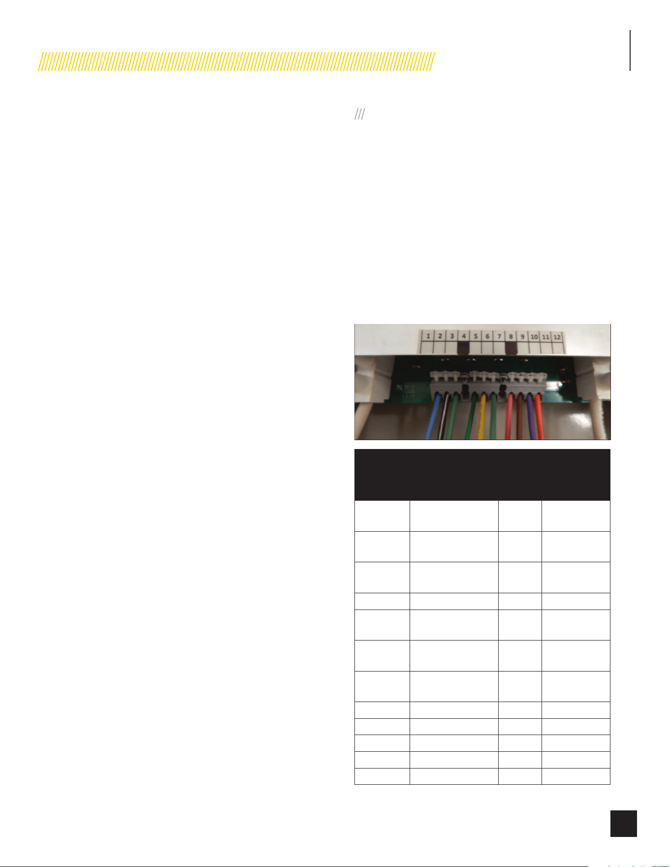
INSTALLATION
57
Part No. 101049
6. Select the circuits to be powered by the HSB backup
generator. If the branch circuit conductor is long enough,
you may want to pull it from the main panel board and
reinstall it in the ATS. It is possible to use an additional
wire and wire connector to extend the branch conductor
in the main panel board through the conduit into the ATS.
Install the branch circuit breakers in the ATS panel for
those branch circuits to be powered by the generator. The
ATS is UL listed for a number of 1 inch interchangeable
breakers (see label on the inside cover of the ATS). If the
breakers are moved from the Utility main panel board
to the ATS, make certain the openings in the dead front
created by removing those breakers from the main panel
board are fitted with the appropriate filler plugs. Connect
each branch circuit conductor to its appropriate branch
circuit breaker. Repeat for each of the selected circuits.
The branch conductors must be connected to the same
ampacity (size) breakers as they were when they were in
the main panel. Make sure that the total ampacity of the
selected circuits does not exceed the maximum capacity
of the generator.
7. Circuits to be moved must be protected by the same size
breaker. For example, a 15 amp 120 volt circuit in the
ATS will replace a 15 amp 120 volt circuit in the main
utility control panel. 15 amp breakers utilize 12 gauge
wire to allow for easy replacement with 20 amp breakers
is required by the installation without the need to replace/
upgrade the wire size.
8. Balance must be maintained when moving circuit
locations from utility main distribution panel to standby
ATS. Circuit breaker positions alternate buss bars
vertically. Circuits sharing a neutral wire should be moved
together in adjacent positions in the ATS or not moved. If
unsure of the proper procedure or if the installation differs
from that described, consult a licensed professional at this
time.
9. Strip wire ½ inch and install a Black L1, Red L2, and
White neutral wire suitable for 50 amperes between the
power output connector on the generator(terminal block
#3) and the similarly-colored terminals on the Generator
Supply terminal block in the ATS. If the generator has
a ground connector, install a ground wire between the
generator and the ground bus in the TS.
INSTALLING COMMUNICATION WIRES
1. All Communication circuit wires are color coded for easy
identification.
2. Route the multi-conductor wires (cable) from the HSB
generator (terminal block #3) to the 12 position center
terminal block in the ATS. Strip the wires ¼ inch and
connect each wire to the terminal block in the sequence
from left to right starting with 1 in the left-most position.
Each wire is connected by pushing the nylon release
lever backward to open the terminal clamp. Inserting the
stripped wire into the terminal opening, releasing the
terminal clamp. Care should be taken not to overstress the
nylon release levers. Note that some of the terminal block
positions are deliberately left unused (TB2-4 and TB2-8).
Terminal
Block
Position
Function Voltage Wire Color
TB2-1
Switch to generator
signal
+24
VDC
L (Blue)
TB2-2
Switch to utility
signal
+24
VDC
B/W (Black/
White)
TB2-3
Switch to –
common return
0 VDC G (Green)
TB2-4 UNUSED
TB2-5
Generator position
micro switch
Switch
closure
G/B (Green/
Black)
TB2-6
Utility position micro
switch
Switch
closure
Y (Yellow)
TB2-7
Position micro
switch common
Switch
closure
G (Green)
TB2-8 UNUSED
TB2-9 Load bus line 1 out 120 VAC P (Pink)
TB2-10 Load bus line 2 out 120 VAC Br (Brown)
TB2-11 Utility line 1 out 120 VAC Pu (Purple)
TB2-12 Utility line 2 out 120 VAC O (Orange)
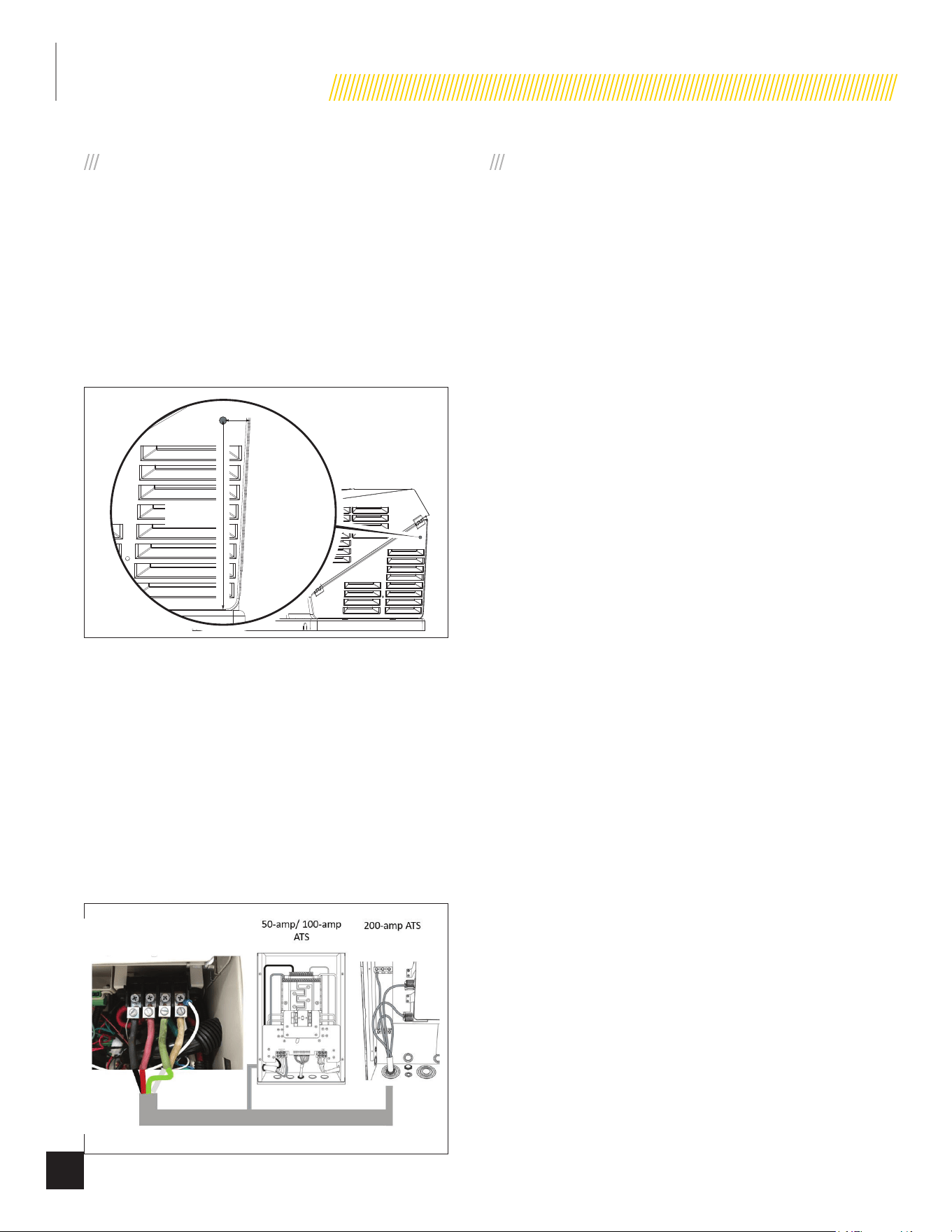
INSTALLATION
58
Part No. 101049
POWER / CONDUCTOR WIRE SIZING
Must comply with National, State, and Local Codes.
It is the responsibility of the installer to perform an installation
that will pass the final electrical inspection. Final inspection
may require the installation of an emergency shut down switch,
installed and located where Home Standby Generator Engine
(prime mover) can be shut down instantly.
If required, the emergency shut down switch should be installed
on the right exterior side panel, mounted near the top door hinge.
See Technical Bulletin 1804-100-30-01 for installation details.
1.5 in. (3.81 cm)
16.25 in.
(41.28 cm)
Conductor wire sizes must be adequate to handle the maximum
current to which they will be subjected to. Conductor sizes are
based on the 75-degree C column of tables, or charts, used to
size conductors.
240-volt Conductor Wires
All HSB Generators provide:
• L1, Black
• L2, Red
• Ground, Green
• Neutral, White
COMMISSIONING THE ATS
1. Turn “OFF” all of the distribution breakers in the ATS.
2. Manually switch the ATS to utility position by moving the
manual lever to the position marked “UTILITY”.
3. Turn “ON” the feeder breaker in the utility distribution
panel.
4. Turn “ON” all distribution breakers and verify that all
connected circuits are functioning properly.
5. Remove the lock-out apparatus if installed or equipped,
and arm the HSB.
6. Your ATS is now fully functional.
7. To test the ATS performance, simply disable utility mains
power. Your HSB generator should start, and your ATS will
automatically switch to the “GENERATOT SUPPLY” source.
When utility mains power is re-established, your ATS will
automatically switch back to the “UTILITY SUPPLY” source,
your HSB generator will cool down, turn off and then be
placed into standby ready position.
8. Refer to the Owner’s and Installation manuals provided
with the HSB and ATS for additional testing information.
9. The installer must label the circuits in the ATS for
reference with the label enclosed with ATS. The customer
information/reference list should also be listed with this
information.
10. All manuals, labels and lists should be kept in or close to
the ATS.
INSTALLATION
59
Part No. 101049
ATS CIRCUIT BOARD FUSE
INFORMATION
!
WARNING
The power from “BOTH” the UTILITY
power source and the HSB “MUST”
be turned “OFF” before attempting
to identified or replace any fuses.
Failure to do so could result in
serious injury or death.
On the backside of the ATS circuit board there are six (6), BUSS
AGC 6 amp fuses. Should any of these fuses blow, the generator
controller will need to be inspected and serviced by a qualified
technician. Once the cause of the blown fuse is resolved, the
fuse will need to be replaced.
To access the fuses on the rear of the circuit board, remove the
4 screws (parts 5 and 6, refer to ATS manual) from the mounting
bracket, and remove the 2 screws from the buss bar(parts 1 and
2, (refer to ATS manual). To access these screws, the branch
circuit breakers will need to be pulled off (removed) from the
buss bar first. The entire buss bar and mechanism assembly
now can be tilted away from the cabinet (toward you), providing
access to the rear of the circuit board and fuses.
Fuse identification, left to right (refer to ATS manual)
1. F1 Utility Solenoid
2. F2 Utility L2 out
3. F3 Utility L1 out
4. F4 Load Buss L2 out
5. F5 Load Buss L1 out
6. F6 Generator solenoid
ATS FUSE TROUBLESHOOTING
AND TESTING
FUSES F2 AND F3
1. If the systems controller shows that load voltage is
available. Fuses F2 and F3 are functional.
2. If not, disconnect the wires that are connected to
terminals 9 and 10 on the 12- position terminal block.
3. With the Utility power on, verify the fact that all circuits
connected to the ATS are energized. Connect an AC
voltmeter between terminals 9 and 10.
4. If the voltmeter reads approximately 240 VAC, fuses F2
and F3 are functional.
5. Remove the voltmeter and reconnect the wires that were
installed in terminals 9 and 10, in the correct order.
FUSES F4 AND F5
1. If the system controller shows that the utility voltage is
available, fuses F4 and F5 are functional.
2. If not, disconnect the wires that are connected to
terminals 11 and 12 on the 12-position terminal block.
3. With utility power on, verify the fact that all circuits
connected to the ATS are energized. Connect and AC
voltmeter between terminals 11 and 12.
4. If the voltmeter reads approximately 240 VAC, fuses F11
and F12, are functional.
5. Remove the voltmeter and reconnect the wires that were
installed in the terminals 11 and 12, in the correct order.
FUSE F1
1. If the system controller will switch the transfer switch from
utility to generator and back, fuse F1 is functional.
2. If not, disconnect the wires that are connected to
terminals 1, 2, and 3 on the 12-position terminal block.
3. With utility power on, verify the fact that all circuits
connected to the ATS are energized. Connect the negative
lead of the 24 VDC power supply to terminal 3.
4. FOR NO MORE THAN 1 SECOND, press the positive lead
of the 24 VDC power supply to terminal 1. If the solenoid
clicks and the mechanism transfers, fuse F1 is functional.
5. Disconnect the 24 VDC power supply and reconnect the
wires that were installed in terminals 1, 2 and 3, in the
correct order.
INSTALLATION
60
Part No. 101049
FUSE F6
1. If the system controller will switch the transfer switch from
utility to HSB generator and back, fuse F6 is functional.
2. If not, disconnect the wires that are connected to
terminals 1, 2 and 3 on 12-position terminal block.
3. With utility power on, verify the fact that all circuits
connected to the ATS are energized.
4. Connect the negative lead of a 24 VDC power supply to
terminal 3.
5. FOR NO MORE THAN 1 SECOND, press the positive lead
of the 24 VDC power supply to terminal 2.
6. If the solenoid clicks and the mechanism transfers, fuse
F2 is functional.
7. Disconnect the 24 VDC power supply and reconnect the
wires that were installed in terminals 1, 2 and 3, in the
correct order.
MANUAL TRANSFER SWITCH
!
WARNING
!
A manual switch is NOT approved by
code when used with a stationary
or permanently installed HSB
generator.
You MUST install an ATS when used with a stationary
or permanently mounted HSB generator by code.
All applicable codes must be followed. The
manufacturer of the switch provides detailed
instructions that must be followed (Champion manual
part number 101271). The Champion HSB requires the
installation of a Champion approved ATS.
!
CAUTION
For standby service, connect output of generator to a
suitably rated transfer switch in accordance with the
Canadian Electrical Code, Part 1.

TROUBLESHOOTING
61
Part No. 101049
TROUBLESHOOTING HSB
The number one problem which relates to starting, output and performance is “Fuel Pressure Insufficient”. Utility fuel regulator and pipe
sized to small which can be compounded by pipe run distance to long for the size of pipe installed. Confirm fuel pressure to the fuel
regulator during No-load and Load operation.
ENGINE WILL NOT CRANK/TURN OVER
1. HSB set in “OFF” mode. Place the HSB controllers in the proper AUTO and ATS start positions.
2. Battery not connected or loose, Connect the batteries according to owner’s manual, clean and tighten the
corroded posts or wires battery connections
3. Battery(s) not charged or low charge. Recharge or replace battery(s).
4. Check for active fault code. Identify fault code, correct and reset.
5. Defective starter solenoid *
6. Defective starter *
GENERATOR WILL CRANK/TURN OVER BUT WILL NOT START
1. Check for active fault code. Identify fault code, correct and reset.
2. Fuel valve(s) turned off. Turn on fuel supply.
3. Fuel pressure insufficient*. Manometer check, confirm fuel pressure to fuel regulator*.
4. Weak battery(s). Recharge or replace battery(s)
5. Low oil level. Check for oil leaks. Check the oil level and add oil if necessary.
6. Spark plug wire is disconnected. Connect spark plug wire.
7. Defective fuel solenoid/regulator. *
ENGINE STARTS, RUNS ROUGH
1. Fuel pressure insufficient*. Manometer check, confirm fuel pressure to fuel regulator*.
2. Wrong fuel jets. Check jets for NG or LPG, change to correct Master Mixer fuel jets.
3. Faulty spark plug, loose spark plug wire. Change spark plug, set gap, connect wire.
4. Plugged air cleaner Clean or replace air cleaner.
5. Generator overloaded*. Remove one or more loads*.
6. Shorted circuit *
HSB STARTS, THEN SUDDENLY STOPS
1. Check for active fault code. Identify fault code, correct and reset.
2. Fuel supply insufficient* Manometer check, confirm fuel pressure to fuel regulator*.
3. Low oil, pressure shut down Check for oil leaks. Check the oil level and add oil if necessary.
4. Generator over loaded Turn off standby circuits for house, reset fault, place unit back into AUTO and
ATS mode. Turn on standby circuits for house. If problem returns contact
Champion or Champion service dealer*.
5. Engine high/over temperature shut down Check all intake and exhaust ventilation around the HSB, remove all debris.
Let HSB sit for 30 minutes to cool down.

TROUBLESHOOTING
62
Part No. 101049
NO AC OUTPUT
1. HSB set in “TEST” mode Place HSB in AUTO and ATS mode.
2. Circuit breaker in “OFF” position Turn on breaker.
3. ATS control in “OFF” mode Place ATS module in ATS mode.
4. Main circuit breaker in “OFF” position. Turn on breaker.
5. Transfer switch breaker in “OFF” position. Turn on breaker.
6. Standby breakers set in “OFF” position. Turn on breaker.
7. Line circuit tripping breaker because of short circuit *
8. Line circuit tripping breaker because of overload *
9. Poor wiring connections*
10. ATS problems*
LED INDICATORS
In all cases when the LED is GREEN, this is an indicator that the HSB is performing properly.
In all cases when the LED is RED, this is an indicator that the HSB has registered a fault and must be corrected. Only the “LOW BATTERY
LED” will not latch out or shut down the HSB. All other RED LED faults will latch out, shut down, disable starting and light the RED LEDS on
the Engine Control Module and the exterior fault code light on the backside of the HSB.
RESET FAULT CODE(S)
There is an exterior fault code indicator light located on the back of the enclosure. This should be checked weekly to make sure there are
no active fault codes.
The fault code(s) can be reset by placing the Engine Control Module in the OFF position for 10 seconds and then placed into ATS mode.
This will reset fault LED, however if a fault code(s) re-occurs it must be addressed.
BATTERY(S) NO OR LOW LEVEL CHARGED, BATTERY(S) DEAD, NEEDS REPLACEMENT, THE EXERCISE TIME MUST BE RESET ONCE
THE BATTERY(S) HAVE BEEN DISCONNECTED.
*Contact Champion Power Equipment, Technical Service toll free 1-877-338-0999,
[email protected] or your nearest Champion dealer.
www.championpowerequipment.com

TROUBLESHOOTING
63
Part No. 101049
HSB AND ATS MODEL & SERIAL REFERENCE, ATS BACK-UP CIRCUITS
HSB Model Number _____________________________________
HSB Serial Number _____________________________________
Fuel Type LPG______________ NG_________________
ATS Model Number ______________________________________
ATS Serial Number ______________________________________
ATS circuits powered ______________________________________
____________________________ ____________________________
____________________________ ____________________________
____________________________ ____________________________
____________________________ ____________________________
____________________________ ____________________________
____________________________ ____________________________
____________________________ ____________________________
Date Installed _____________________________________
Dealer/Installer _____________________________________________________
Address _____________________________________________________
_____________________________________________________
Phone _____________________________________________________
Cell _____________________________________________________
Purchased from _____________________________________________________

Champion Power Equipment
6370 S Pioneer Way, Unit 101
Las Vegas, NV 89113 USA
Made in China

10 YEAR LIMITED WARRANTY*
Basic Warranty Provisions
Champion Air-Cooled 8.5kW – 22kW Home
Standby Units USA and Canadian Models
For a period of 10 years or 2000 hours (whichever occurs first)
from successful activation by an Authorized Champion Home
Standby Dealer, Champion Power Equipment will, at its option,
repair or replace any part(s) which upon examination, inspection
and testing by Champion Power Equipment or an Authorized
Champion Home Standby Dealer is found to be defective under
normal use and service, in accordance with the Warranty
Schedule set forth below.
Any equipment that the purchaser/owner claims to be defective
must be examined by the nearest Authorized/Certified Champion
Home Standby Service Dealer. This warranty applies only to
Champion Power Equipment automatic standby generators used
in “Standby” applications as Champion has defined Standby.
Scheduled Maintenance, as outlined by the generator owner’s
manual is required. This Scheduled Maintenance should be
performed by a knowledgeable, experience operator or an
Authorized/Certified Champion Home Standby Service Dealer.
WARRANTY SCHEDULE
Years 1 and 2 – Limited comprehensive coverage on mileage,
labor and parts
Years 3 through 10 – Limited comprehensive coverage on
parts only
GUIDELINES:
– Warranty begins upon the successful activation of the unit.
– Unit should be Registered and Proof of Purchase and
Maintenance must be available.
– Warranty is transferable between ownership of original
installation site.
– Warranty only applies to permanently wired and mounted
units.
– Any and all warranty repairs and/or concerns must be
performed and/or addressed by an Authorized/Certified
Champion Home Standby Service Dealer. Repairs or
diagnostics performed by individuals other than Authorized/
Certified Champion Home Standby Service Dealers not
authorized in writing by Champion Power Equipment will not be
covered.
– A Champion approved Transfer Switch is highly recommended
to be used in conjunction with the generator set. The
Champion Transfer Switch is covered under its own, separate
warranty listed in the Transfer Switch Instruction Manual and
is not covered under this warranty schedule.
– If a Non-Champion approved Transfer Switch is substituted
for use and directly causes damage to the generator set, no
warranty coverage shall apply.
– Steel enclosures are warranted against rusting for the first
year of ownership only. Damage caused after receipt of
generator is the responsibility of the owner and is not covered
by this warranty. Nicks, scrapes, dents or scratches to the
painted enclosure should be repaired promptly by the owner.
– All warranty expense allowances are subject to the conditions
defined in Champion Power Equipment “Home Standby”
Warranty Policy and Procedures Manual.
THIS WARRANTY SHALL NOT APPLY TO THE
FOLLOWING:
– Original installation or start-up costs
– Champion Home Standby generators that utilize non-Champion
Power Equipment replacement parts
– Costs of normal maintenance (i.e. tune-ups, associated part(s),
adjustments, loose/leaking clamps, installation and start-up)
– Units sold, rated or used for “Prime Power”, “Trailer Mounted”
or “Rental Unit” applications
– Damage to generator system (including transfer switch)
caused by improper installation or costs necessary to correct
installation
– Units used for Prime Power in place of existing utility power
(where utility power is present) or in place of utility power
where utility power service does not normally exist. Prime
power includes any application that does not use the utility
grid for electric power (example: Solar power)
– Fuel connections other than conventional utility company
supplied natural gas systems or conventional LP vapor
withdrawal systems
– Any failure caused by contaminated fuels, oils or lack of proper
fuels, oils or failure to perform scheduled maintenance and
service the air filter
– Steel enclosures that are rusting due to the improper
installation, location in a harsh or saltwater environment or
scratched where integrity of paint applied is compromised
– Failures due, but not limited, to normal wear and tear,
accident, misuse, abuse, negligence or improper installation.
As with all mechanical devices, the Champion engines need
periodic part(s) service and fluid replacement to perform as
designed.
– Failures caused by any external cause or act of God, such as
collision, theft, vandalism, riot or wars, nuclear holocaust,
fire, freezing, lightning, earthquake, windstorm, hail, volcanic
eruption, water or flood, tornado or hurricane
– Damage related to rodent and/or insect infestation
– Covered warranty labor rates are based on normal working
hours. Overtime, holiday, or emergency labor costs for repairs
outside of normal business hours will be the responsibility of
the customer

– Any incidental, consequential or indirect damages caused by
defects in materials or workmanship, or any delay in repair or
replacement of the defective part(s)
– Failure due to misapplication to provide sufficient cooling air
and to regularly exercise the generator under load
– Telephone, cellular phone, facsimile, internet access or other
communication expenses
– Living or travel expenses of person(s) performing service,
except as specifically included within the terms of a specific
unit warranty period
– Expenses related to “customer instruction” or troubleshooting
where no manufacturing defect is found
– Rental equipment used while warranty repairs are being
performed and/or overnight freight costs for replacement
part(s)
– Costs incurred for equipment used for removal and/or
reinstallation of generator, (i.e.: cranes, hoists, lifts, etc.)
– Planes, ferries, railroad, buses, helicopters, snowmobiles,
snow-cats, off-road vehicles or any other mode of transport
deemed abnormal
– Starting batteries, fuses, light bulbs, engine fluids, and spark
plugs
THIS WARRANTY AND THE ATTACHED U.S. EPA WARRANTY
ARE IN LIEU OF ALL OTHER WARRANTIES, EXPRESS OR
IMPLIED, INCLUDING WARRANTIES OF MERCHANTABILITY OR
FITNESS FOR A PARTICULAR PURPOSE.
Any implied warranties which are allowed by law, shall be limited
in duration to the terms of the express warranty provided herein.
Some states do not allow limitations on how long an implied
warranty lasts, so the above limitation may not apply to purchaser/
owner.
CHAMPION POWER EQUIPMENT’S ONLY LIABILITY SHALL BE
THE REPAIR OR REPLACEMENT OF PART(S) AS STATED ABOVE.
IN NO EVENT SHALL CHAMPION POWER EQUIPMENT BE
LIABLE FOR ANY INCIDENTAL, OR CONSEQUENTIAL DAMAGES,
EVEN IF SUCH DAMAGES ARE A DIRECT RESULT OF CHAMPION
POWER EQUIPMENT’S NEGLIGENCE.
Some states do not allow the exclusion or limitation of incidental
or consequential damages, so the above limitations may not apply
to purchaser/owner. Purchaser/owner agrees to make no claims
against Champion Power Equipment based on negligence. This
warranty gives purchaser/owner specific legal rights. Purchaser/
owner also may have other rights that vary from state to state.
To obtain warranty service or your nearest Champion Home
Standby Dealer call Champion Power Equipment Customer Service
toll free 1-877-338-0999.
Contact Information
Address
Champion Power Equipment, Inc.
Customer Service
6370 S Pioneer Way, Unit 101
Las Vegas, NV 89113 USA
www.championpowerequipment.com
Customer Service and Techinical Support
Toll Free: 1-877-338-0999
hsb@cpeauto.com
Fax no.: 1-562-236-9429
*Except as otherwise stipulated in any of the following enclosed Emission Control System Warranties (when applicable) for the Emission Control System: U.S. Environmental Protection Agency
(EPA) and/or California Air Resources Board (CARB).