
FORCE
®
KRAKEN TROLLING MOTOR
INSTALLATION INSTRUCTIONS
Getting Started
WARNING
See the Important Safety and Product Information guide in the product box for product warnings and other
important information.
Failure to install this device according to these instructions could result in personal injury, damage to the vessel
or device, or poor product performance.
Do not run the motor when the propeller is out of the water. Contact with the rotating propeller may result in
severe injury.
Do not use the motor in areas where you or other people in the water may come into contact with the rotating
propeller, which could result in severe injury.
Always disconnect the motor from the battery before handling or working with the propeller, propeller drive
motor, electrical connections, or electronics enclosures to avoid serious injury or death.
CAUTION
For the best possible performance and to avoid potential injury, damage to the device, or damage to your vessel,
installation by a qualified marine installer is recommended.
To avoid possible personal injury, always wear safety goggles, ear protection, and a dust mask when drilling,
cutting, or sanding.
When stowing or deploying the motor, be aware of the risk of entrapment or pinching from moving parts, which
can result in personal injury.
When stowing or deploying the motor, maintain stable footing and be aware of slick surfaces around the motor.
Losing your footing while stowing or deploying the motor may result in injury.
NOTICE
When drilling or cutting, always check what is on the opposite side of the surface to avoid damaging the vessel.
Tools and Supplies Needed
• Drill and a
11
/
32
in. (9mm) drill bit
• #2 Phillips screwdriver
• 4mm hex bit or wrench
•
1
/
2
in. (13mm) socket
• Torque wrench
• Circuit breaker rated for continuous 60A
• Trolling motor plug and receptacle rated for 60A or greater (optional)
• 6, 4, or 2AWG (16, 25, or 35mm
2
) wire for extended runs of the power cable
• Solder and heat-shrink tubing, if extending the power cable
• Stainless steel pan head
5
/
16
-20 (M8x1) bolts (if the included bolts are not long enough to mount the motor
to the deck)
GUID-09FCEEF1-A8CD-4B9C-8A62-161A75852017 v6
April 2025
Installation Preparation
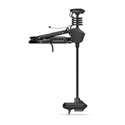
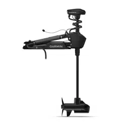
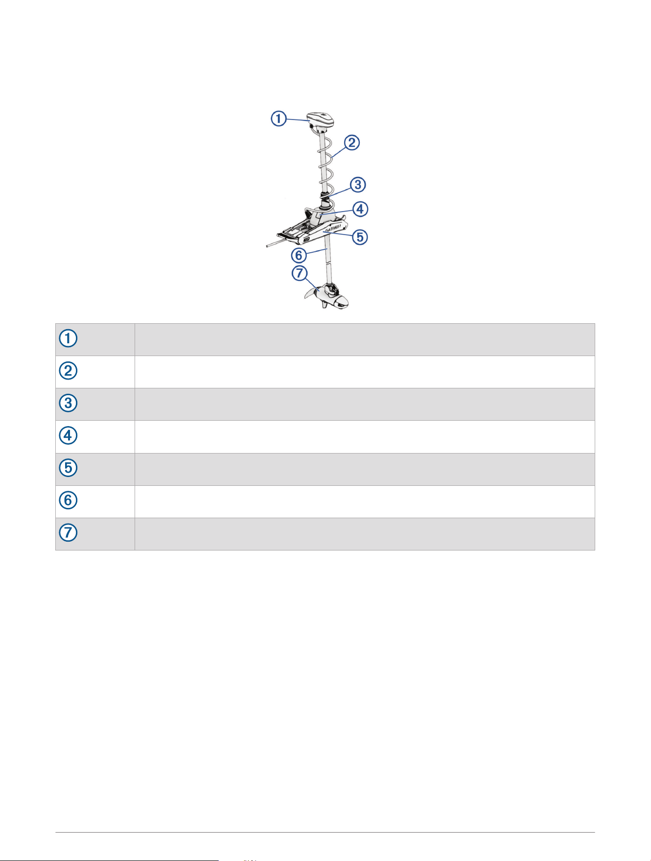
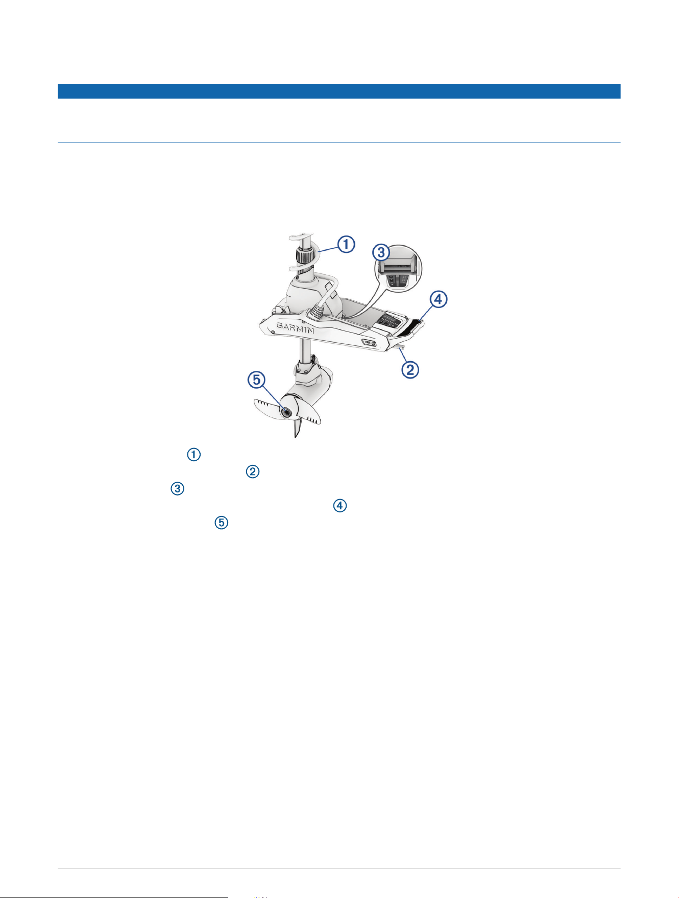
Device Overview
Shaft cap
Power and transducer cables
Depth-adjustment collar
Steering system
Mount
Shaft
Propeller drive motor
2
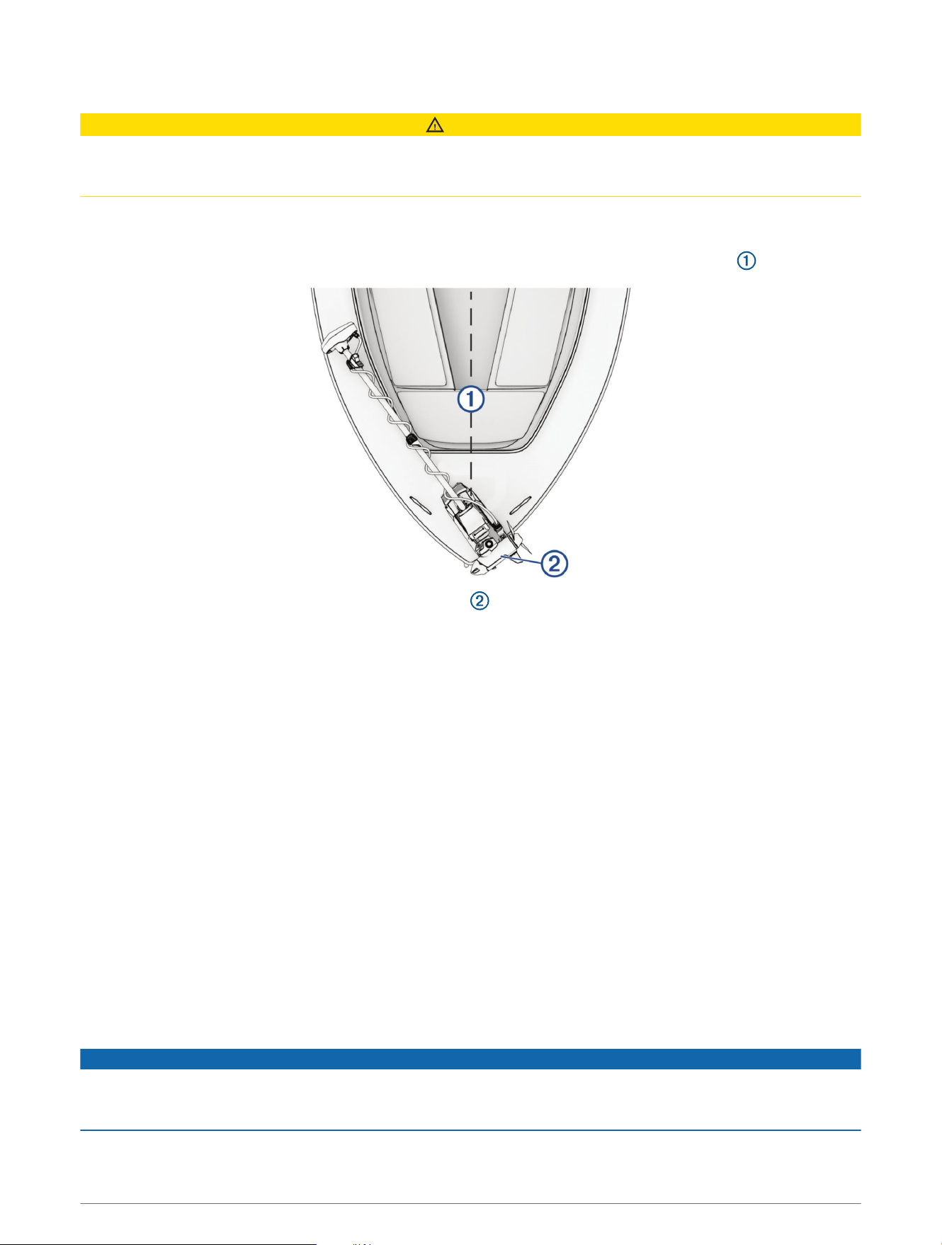
Mounting Considerations
CAUTION
You must install the motor in a location where no large metallic objects, such as a tool box, are near the display
panel when it is deployed. Large metallic objects can interfere with the magnetic compass, affecting the built-in
autopilot performance and potentially leading to personal injury or property damage.
When selecting a mounting location, observe these considerations.
• You must install the motor on the bow of your boat.
• You should install the mount so the deployed motor is as close to the centerline of the boat as possible.
• You must install the mount with the top of the cutout overhanging the gunwale of the boat. The U shape
should extend over the side of the boat.
NOTE: If there is not enough room on the gunwale to install all six bolts, a minimum of four bolts must be
used.
• The motor secures to the deck of the boat using bolts, so you must have room to secure the mount from the
underside using washers and nuts.
• The motor must have clearance to move from the deployed to the stowed position and back again, so the
installation location must be clear of obstacles.
• Verify that the deck is strong enough for the weight and force of the trolling motor. Use a backing plate or
reinforce the boat if needed.
Connection Considerations
When making the wiring connections, observe the following considerations.
• You must connect the trolling motor to a 24or 36Vdc battery bank capable of supplying 60A continuously.
• You must connect to the power source through a circuit breaker rated for continuous 60A (not included).
• If necessary, you can extend the power cable using the appropriate wire gauge based on the length of the
extension (Power Cable Extensions, page7).
• For convenience, you can install a trolling motor plug and receptacle rated for 60A or greater (not included)
in the bulkhead to make it easier to disconnect the motor from the power source.
Installation Procedures
NOTICE
When assembling the motor, you must use hand tools to install all of the parts, observing the torque
specifications when provided. Using power tools to assemble the motor may damage the components, and
voids the warranty.
3
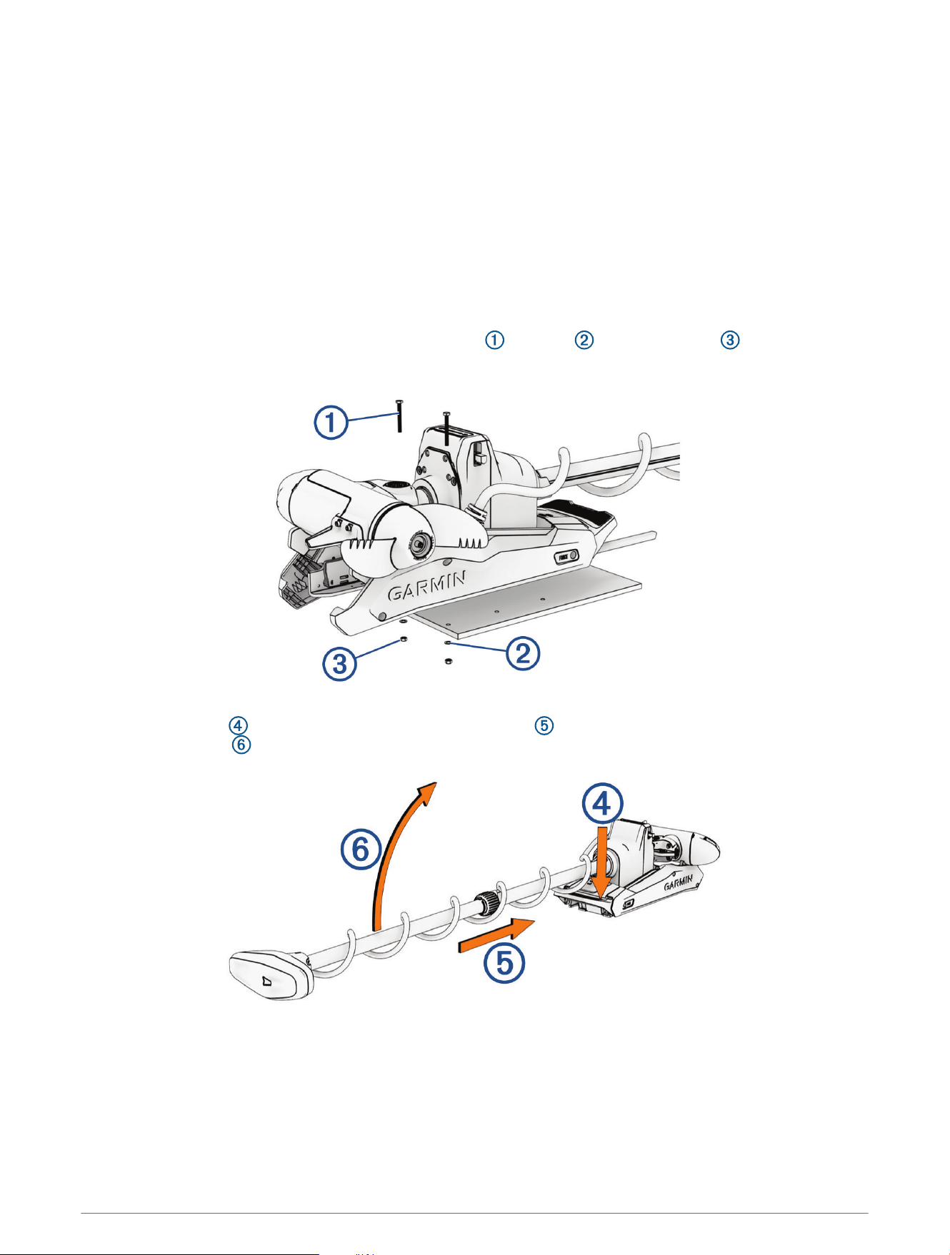
Installing the Motor on the Deck
NOTE: If the supplied bolts are not long enough for the mounting surface, you must obtain the appropriate
length stainless steel pan head
5
/
16
in. -20 (M8x1) bolts.
1 Select a mounting location on the bow of your boat, according to the mounting considerations.
2 Place the included mounting template on the mounting location with the mount on the template overhanging
the gunwale or the edge of the boat deck.
3 Mark the mounting hole locations on the boat deck.
NOTE: Use the six symmetrical holes in the mount for standard installation. The seventh hole is not needed
for most installations.
4 Using a
11
/
32
in. (9mm) drill bit, drill the mounting holes.
5 Place the motor on the boat deck, aligning the holes on the mount with the mounting holes.
6 Secure the mount to the deck using the included bolts , washers , and locking nuts in the two holes
closest to the gunwale or edge of the boat deck.
7 Adjust the depth stop so that the motor can deploy without hitting the ground.
8 Press the release , slide the propeller drive motor head out , and gently pivot the trolling motor into the
deployed position .
4
9 Secure the mount to the deck using the included bolts , washers , and locking nuts in the remaining
holes.
10 Tighten the nuts to a torque of 14.9N-m (11lbf-ft.).
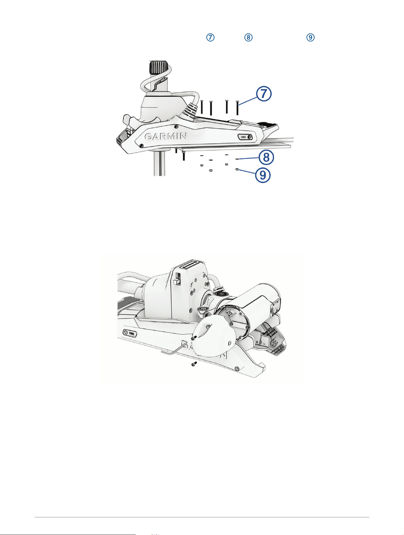
Installing the Nose Cone
NOTE: Most models come fully assembled. This procedure is only required for the 90-inch Force Kraken Trolling
Motor.
Using a 4mm hex bit or wrench, secure the nose cone to the front of the propeller drive motor using the two
included screws, ensuring the tab is on the bottom.
5
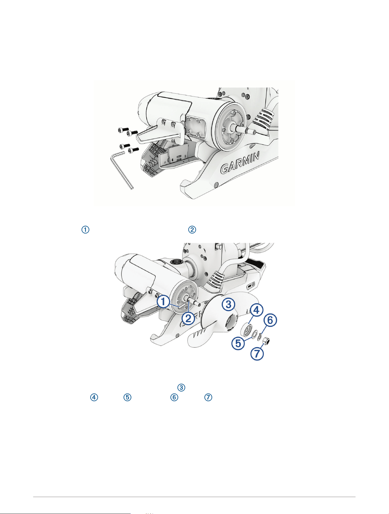
Installing the Skeg
NOTE: Most models come fully assembled. This procedure is only required for the 90-inch Force Kraken Trolling
Motor.
Using a 4mm hex bit or wrench, secure the skeg to the propeller drive motor using the four included screws,
ensuring the longer end of the skeg faces the propeller side.
Installing the Propeller
1 Insert the pin through the propeller motor shaft .
2 If necessary, rotate the motor shaft to orient the pin horizontally so it is less likely to fall out during
installation.
3 Align the channel on the inside of the propeller with the pin, and slide the propeller onto the motor shaft.
4 Place the anode , washer , lock washer , and nut onto the end of the motor shaft.
5 Using a
9
/
16
in. (14mm) socket, tighten the lock nut to 16.27N-m (12 lbf-ft) to secure the propeller.
6

Connecting to Power
WARNING
To avoid possible serious personal injury or property damage, the circuit breaker must be in the off position
before you connect the power cables from the trolling motor.
1 Route the power cable to the breaker panel or the location where you plan to install the breaker.
2 If necessary, extend the power cable using the appropriate wire gauge based on the length of the extension
(Power Cable Extensions, page7) using solder and heat-shrink tubing.
3 Install a trolling motor plug and receptacle rated for 60A or greater where the power cable enters a bulkhead
(optional).
4 Connect the power cable to a circuit breaker rated for 60A (continuous).
5 If necessary, connect the circuit breaker to a 60A, 24 or 36Vdc power source.
Power Cable Extensions
CAUTION
You must follow these requirements when extending the power cables for this product. Improperly extended
power cables will cause excess electrical current, potentially leading to personal injury or property damage.
• You must use single-conductor stranded wire with insulation rated for at least 75°C (167°F) that is not
bundled, not sheathed, and not run through conduit.
NOTE: If you are using wire with insulation rated for at least 105°C (221°F), and it is run outside of engine
spaces, you can bundle up to three wires inside a sheath or conduit.
• When installing the extension, you must follow all industry standards and best practices.
• You must use the appropriate wire gauge based on the length of the extension.
Extension length Minimum wire gauge Optimal wire gauge
0 to 3m (0 to 10ft. ) 6AWG (16mm
2
) 6AWG (16mm
2
)
3 to 4.6m (10 to 20ft.) 6AWG (16mm
2
) 4AWG (25mm
2
)
4.6 to 9.1m (20 to 30ft.) 6AWG (16mm
2
) 2AWG (35mm
2
)
Connecting the Transducer to a Chartplotter
Select Force Kraken Trolling Motor models include a built-in transducer. If your model does not include a
transducer, you must install one before you can connect it to a compatible chartplotter.The built-in 12-pin
transducer is compatible with select Garmin
®
chartplotter models. Go to garmin.com or contact your Garmin
dealer for more information.
1 Route the transducer cable to the installed chartplotter. If necessary, connect the included extension cable or
a longer extension cable.
2 Install the locking collar on the end of the transducer cable.
3 Connect the transducer cable to the transducer port on the back of the chartplotter.
You can refer to the instructions provided with your chartplotter to identify the transducer port.
Stabilizer Installation
The stabilizer is an optional accessory that can provide additional support for the trolling motor when it is in the
stowed position.
NOTE: The stabilizer is only included with the Force Kraken 90” Trolling Motor.
Installation instructions for the stabilizer are provided in the stabilizer box.
7
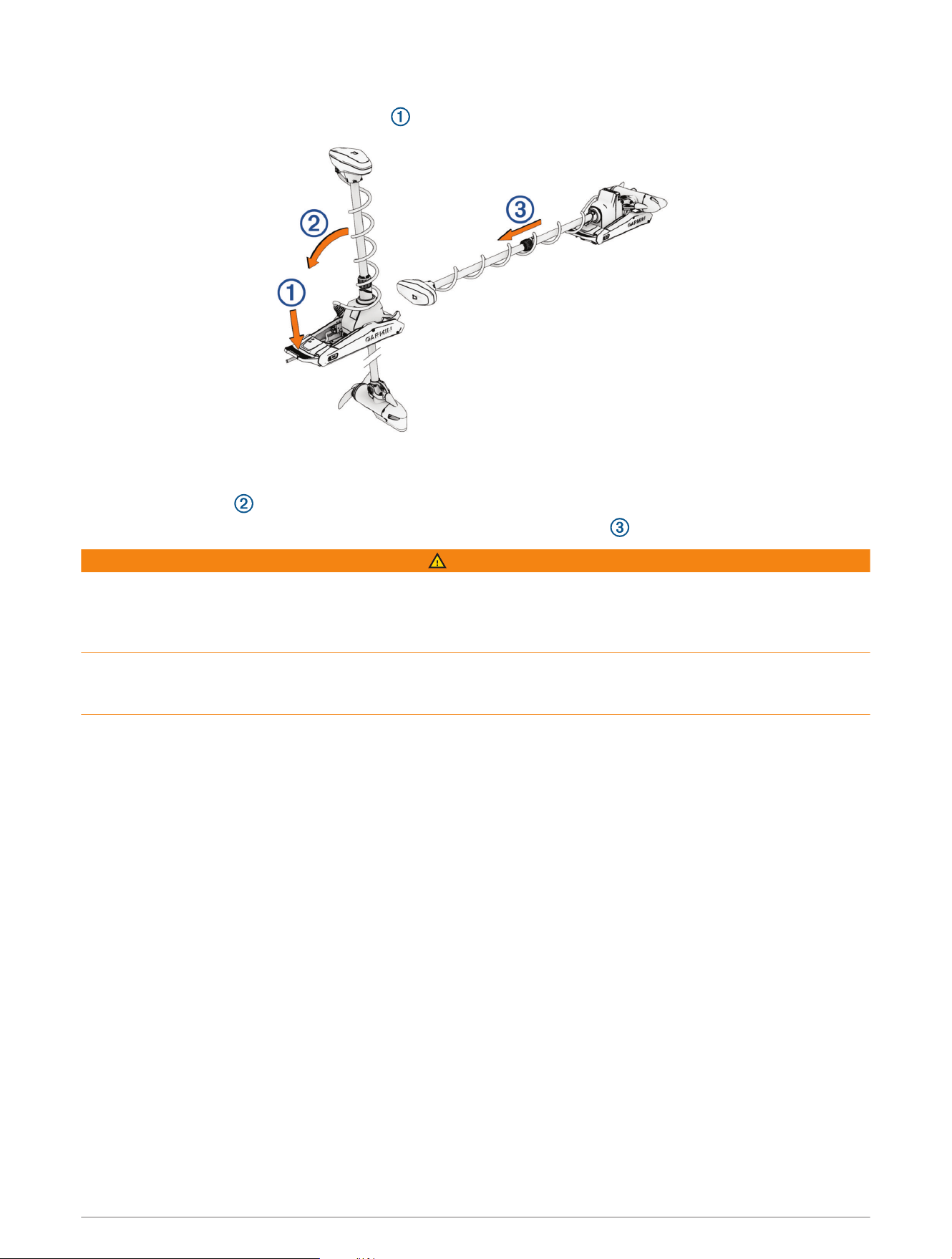
Stowing the Motor from the Deployed Position
1 Hold down the pedal to release the latch .
NOTE: The motor should automatically steer to 90° for stowing. The propeller stow side can be configured in
the settings menu.
2 Tilt the shaft back , and then raise the motor slowly while tilting the shaft to the horizontal position.
3 Slide the motor into the motor catch until it locks in the stowed position .
WARNING
Push forward along the length of the shaft, and then pull backward along the length of the shaft to ensure that
the motor is firmly locked in place. If the motor is not firmly locked in the stowed position, the motor may deploy
unexpectedly while in rough waters or trailering, which could result in possible property damage or serious
personal injury.
The depth adjustment collar must be moved as close to the base of the motor as possible. Failure to do so
could cause unexpected trolling motor deployment, leading to potential property damage or serious personal
injury.
4 If installed, clamp the motor shaft in the stabilizer.
Remote Control Installation
The remote control connects to the trolling motor wirelessly and is paired at the factory.
Operation instructions are included in the Force Kraken Trolling Motor Quick Start Manual.
8
Maintenance Needs and Schedule
NOTICE
After using the motor in salt water or brackish water, you must rinse off the entire motor with fresh water, and
apply a water-based silicone spray using a soft cloth. You must avoid spraying jets of water at the shaft cap, to
prevent water ingress that could lead to product damage.
To maintain your warranty, you must perform a series of routine maintenance tasks as you prepare your motor
for the season. If you use or transport the motor in salt water or dry, dusty environments (traveling on gravel
roads, for example) you should perform these tasks more often during the season.
For detailed procedures and information on service and replacement parts, go to garmin.com/manuals/kraken
_trolling_motor to download the Force Kraken Trolling Motor Maintenance Manual.
• Examine the coil cable for wear, and replace it as necessary.
• Check and clean the power cables .
• Lubricate the hinge with marine grade grease.
• Clean and lubricate the stow and deploy latch pedal and latch bar.
• Clean or replace the anodes in the propeller drive motor.
• Remove entangled fishing line and other obstructions from the propeller.
9
Motor Information
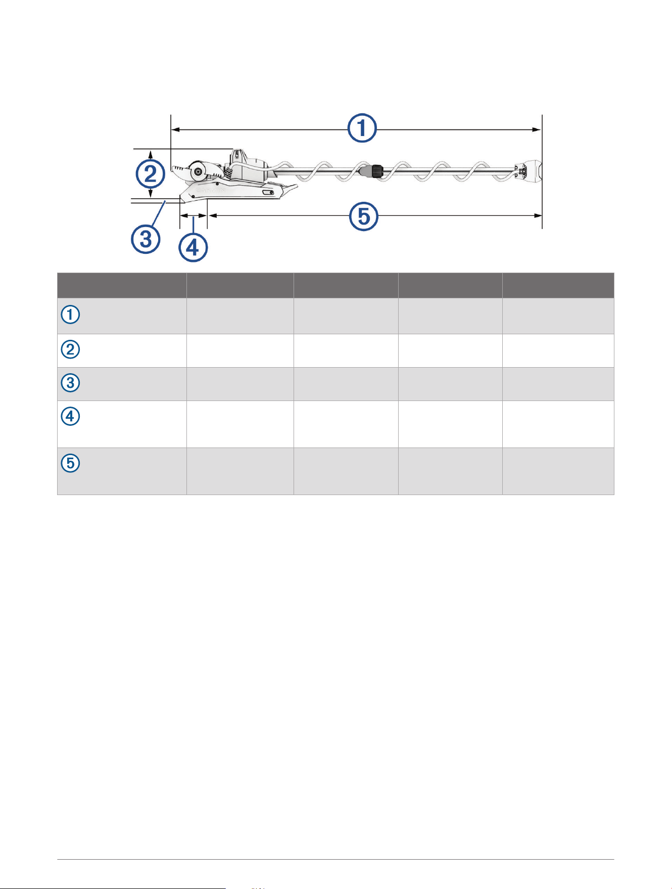
Stowed Dimensions
Item 48 in. Model 63in. Model 75in. Model 90in. Model
overall length
156cm (61
7
/
16
in.)
194.1cm
(76
7
/
16
in.)
224.8cm
(88
1
/
2
in.)
262.68 cm
(103
3
/
8
in.)
mount height
26.2cm (10
5
/
16
in.) 26.2cm (10
5
/
16
in.) 26.2cm (10
5
/
16
in.) 26.2cm (10
5
/
16
in.)
overhang height
1.7cm (
11
/
16
in.) 1.7cm (
11
/
16
in.) 1.7cm (
11
/
16
in.) 1.7cm (
11
/
16
in.)
minimum overhang
length
20.7 cm (8
1
/
8
in.) 20.7 cm (8
1
/
8
in.) 20.7 cm (8
1
/
8
in.) 20.7 cm (8
1
/
8
in.)
maximum length on
boat
130.2cm
(51
5
/
16
in.)
168.3cm
(66
1
/
4
in.)
206.4cm
(81
1
/
4
in.)
236.88 cm
(93
1
/
4
in.)
10
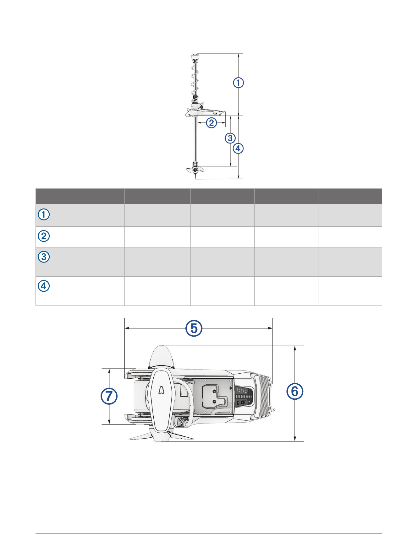
Deployed Dimensions
Item 48 in. Model 63in. Model 75in. Model 90in. Model
minimum height
48.6cm (19
1
/
8
in.).
48.6cm
(19
1
/
8
in.).
48.6cm
(19
1
/
8
in.).
48.6cm
(19
1
/
8
in.).
mount length on deck
46cm (18
1
/
8
in.) 46cm (18
1
/
8
in.) 46cm (18
1
/
8
in.) 46cm (18
1
/
8
in.)
maximum propeller
depth
87.95cm (34
5
/
8
in.)
126cm (49
5
/
8
in.)
156.5cm (61
5
/
8
in.)
194.6cm (76
5
/
8
in.)
maximum distance to
from mount to skeg tip
107.32cm
(42
1
/
4
in.)
145cm (57
1
/
4
in.)
175.9cm
(69
1
/
8
in.)
213.7cm
(84
1
/
8
in.)
11

Item All Models
mount length
61.2 cm (24
1
/
8
in.)
motor head length
With transducer: 42.7 cm(16
13
/
16
in.)
Without transducer: 41.2 cm (16
1
/
4
in.)
mount width
24.6cm (9
11
/
16
in.)
Specifications
Trolling Motor
Weight (motor, mount,
and cables)
48in. white model:22.6kg (50lb.)
48in. black model:23.2kg (51lb.)
63in. white model:24kg (53lb.)
63in. black model:24.5kg (54lb.)
75in. white model: 24.5 kg (54lb.)
75in. black model: 25.4 kg (56lb.)
90in. white model: 25kg (55lb.)
Weight (stabilizer) 0.66kg (1.45lb.)
Operating temperature From -5° to 40°C (from 32° to 104°F)
Storage temperature From -40° to 85°C (-40° to 185°F)
Material
Mount and motor housing: aluminum
Shaft cap, display panel, and side panels: plastic
Motor shaft: fiberglass
Water rating
Shaft cap: IEC 60529 IPX5
1
Steering motor housing: IEC 60529 IPX7
2
Display panel housing: IEC 60529 IPX7
2
Propeller drive motor housing: IEC 60529 IPX8
3
Compass safe distance 61cm (2ft.)
Power cable length 1.2m (4ft.)
Input voltage From 20 to 45Vdc
Input amperage 60A continuous
Breaker (not included)
42VDC or greater, suitable for 60A continuous
NOTE: You can protect the system by using a larger circuit breaker, not to exceed
90A, if you are operating under high temperatures or if you are sharing the circuit
with other devices. You should verify that your boat wiring meets marine wiring
standards using a larger breaker before changing it.
Main power usage at
36Vdc 60A
Off: 72mW
Full power: 2160W
Radio frequency 2.4GHz @ 17.4dBm Max
1
The part withstands projected water exposure from any direction (such as rain).
2
The part withstands incidental immersion in water up to 1m deep for up to 30min.
3
The part withstands continuous immersion in water up to 3m deep.
12

Remote Control
Dimensions (W×H×D) 152 x 52 x 32mm (6 x 2 x 1
1
/
4
in.)
Weight 109g (3.8oz.) without batteries
Material Glass-filled nylon
Display type Sunlight-visible, transflective memory-in-pixel (MIP)
Display resolution R240 x 240 pixels
Display size (diameter) 30.2mm (1
3
/
16
in.)
Operating temperature From -15° to 55°C (5° to 131°F)
Storage temperature From -40° to 85°C (-40° to 185°F)
Battery type 2 AA (not included)
Battery life 240 hr., typical use
Radio frequency 2.4GHz @ 3.4dBm nominal
Water rating IEC 60529 IPX7
4
Compass-safe distance 15cm (6in.)
联系信息
制造厂商 : 台湾国际航电股份有限公司
销售厂商 : 上海佳明航电企业管理有限公司
联络地址 : 上海市徐汇区桂平路 391 号 ( 新漕河泾国际商务中心 A 座 37 层 )
电 话 : 021-60737675
客服专线 : 400-819-1899
聯絡地址
製造銷售: 台灣國際航電股份有限公司
聯絡地址: 新北市汐止區樟樹二路 68 號
電 話:(02)2642-8999
客服專線:(02)2642-9199
4
Withstands incidental exposure of water up to 1m for up to 30min.
13
物質宣言
部件名称
有毒有害物质或元素
铅 汞 镉 六价铬 多溴联苯
多溴二苯
醚
邻苯二甲酸
二(2-乙基
己)酯
邻苯二甲
酸丁苄酯
邻苯二甲
酸二丁酯
邻苯二甲
酸二异丁
酯
印刷电路板组
件
金属零件
电缆 电缆组件
连接器
塑料和橡胶零
件
本表格依据 SJ/T11364 的规定编制。
: 代表此种部件的所有均质材料中所含的该种有害物质均低于
(GB/T26572) 规定的限量
: 代表此种部件所用的均质材料中, 至少有一类材料其所含的有害物质高于
(GB/T26572) 规定的限量
* 该产品说明书应提供在环保使用期限和特殊标记的部分详细讲解产品的担保使用条件。
产品
이기기는업무용환경에서사용할목적으로
적합성평가를받은기기로서가정용환경에서
사용하는경우전파간섭의우려가있습니다
© 2023 Garmin Ltd. or its subsidiaries
Garmin
®
, the Garmin logo, ActiveCaptain
®
, and Force
®
are trademarks of Garmin Ltd. or its subsidiaries, registered in the USA and other countries. These trademarks may
not be used without the express permission of Garmin.
You should reference United States Code of Federal Regulations: 33 CFR 183 - Boats and Associated Equipment and ABYC E-11: AC and DC Electrical Systems on
Boats when installing this trolling motor.
MN: A04109 / B04109 / C04109 / D04109 / E04109
拖釣推進器
© 2023 Garmin Ltd. or its subsidiaries
support.garmin.com