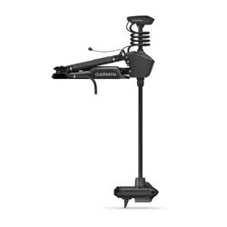

FORCE
®
PRO TROLLING MOTOR
Field Service Manual

© 2025 Garmin Ltd. or its subsidiaries
All rights reserved. Under the copyright laws, this manual may not be copied, in whole or in part, without the written consent of Garmin. Garmin reserves the right to change
or improve its products and to make changes in the content of this manual without obligation to notify any person or organization of such changes or improvements. Go to
www.garmin.com for current updates and supplemental information concerning the use of this product.
Garmin
®
, the Garmin logo, ActiveCaptain
®
, and Force
®
are trademarks of Garmin Ltd. or its subsidiaries, registered in the USA and other countries. These trademarks may not be used
without the express permission of Garmin.
TORX
®
is a registered trademark of Acument Intellectual Properties, LLC in the United States or other countries.

Table of Contents
Important Information...................... 1
Tools, Supplies, and Equipment
Needed..................................................... 1
Service Kits...................................... 1
Drive System............................................ 2
Mount....................................................... 5
Other Service Kits.................................... 7
Service Procedures.......................... 8
Replacing the Propeller........................... 8
Replacing the Pull Cable......................... 9
Removing the Power and Transducer
Cables From the Mount........................ 12
Removing the Steering System from the
Mount..................................................... 14
Removing the Shaft from the Steering
System................................................... 18
Removing the Depth-Adjustment
Collar...................................................... 23
Removing the Propeller Drive Motor from
the Shaft................................................ 23
Removing the Transducer Cable from
the Shaft................................................ 26
Removing the Transducer from the Nose
Cone....................................................... 28
Replacing the Nose Cone..................... 28
Installing the Propeller Drive Motor on
the Shaft................................................ 29
Installing the Shaft in the Steering
System................................................... 32
Connecting the Steering System to the
Mount..................................................... 37
Replacing the Lower Gas Spring.......... 44
Replacing the Upper Gas Spring.......... 45
Removing the Power Cable from the
Steering System.................................... 46
Removing the Coil Cable from the
Steering System.................................... 48
Removing the Coil Cable from the Shaft
Cap......................................................... 49
Replacing the Display Panel................. 50
Removing the Upper Link from the
Mount Base........................................... 51
Removing the Lower Link from the
Mount Base........................................... 52
Replacing the Latch Mechanism in the
Lower Link............................................. 54
Replacing the Mount Base....................55
Replacing the Mount Shrouds.............. 56
Replacing the Mount Rails.................... 56
Replacing the Mount Bumper............... 57
Replacing the Stow Support................. 57
Removing the Electronics Cover.......... 58
Replacing the PCB.................................59
Opening the Steering System
Housing..................................................60
Removing the Steering Servo Motor and
Shaft Carrier.......................................... 62
Replacing the Steering Position
Sensor.................................................... 65
Table of Contents i


Important Information
WARNING
See the Important Safety and Product Information guide in the product box for product warnings and other
important information.
Failure to follow these warnings, cautions, and notices could result in personal injury, damage to the vessel or
device, or poor product performance.
You must perform the services and repairs described in this document according to the instructions provided.
Failure to do so could result in damage to the trolling motor or its components or could result in serious
personal injury.
Repairing and performing maintenance on Garmin
®
electronics is complex work that can result in serious
personal injury or product damage if not done correctly.
Always disconnect the motor from the battery before handling or working with the propeller, propeller drive
motor, electrical connections, or electronics enclosures to avoid serious injury or death.
CAUTION
When stowing or deploying the motor, be aware of the risk of entrapment or pinching from moving parts, which
can result in personal injury.
When stowing or deploying the motor, maintain stable footing and be aware of slick surfaces around the motor.
Losing your footing while stowing or deploying the motor may result in injury.
NOTICE
Garmin is not responsible for, and does not warrant, the work that you or a non-authorized repair provider
perform on your product.
Tools, Supplies, and Equipment Needed
• Suitable workbench or table
◦ Must be at least 8ft. (2.5m) long for working on the 50in. models
◦ Must be at least 10ft. (3m) long for working on the 57in. models
• #0, #1, #2, and #3 Phillips screwdrivers
•
3
/
32
in., 3 mm, 4mm, and 8mm hex bits or wrenches
• 10 and 15 mm socket
• T-10 TORX
®
screwdriver (for removing the electronics cover)
• 29mm socket or wrench (for replacing the PCB)
•
9
/
16
in. (15mm) socket (for removing the propeller)
• 36mm or adjustable wrench (for replacing the coil cable)
• Torque wrench
◦ With 4mm, 6mm, and 8mm hex bits
◦ Capable of measuring torque from 0.5N-m (4.5lbf-in) to 17N-m (150lbf-in)
• Synthetic or marine grade general-purpose grease
• Needle-nose pliers
• Dielectric grease (for replacing the power cable or coil cable)
Service Kits
You can order the most common replacement parts and accessories at garmin.com/accessories/force_pro
_trolling_motor.
To order the service parts listed in this manual, you can contact Garmin Support at 1-800-800-1020 or go to
support.garmin.com.
If you are a Garmin dealer, you should contact your Garmin representative to order service parts.
Important Information 1
Drive System
Description Service Kit Number Notes
Drive System
50 in. model: S10-U3011-00
57 in. model: S10-U3011-10
Assembled drive system including steering system, shaft, propeller
drive and shaft cap.
Removing the Steering System from the Mount, page14
Drive System Service Kits
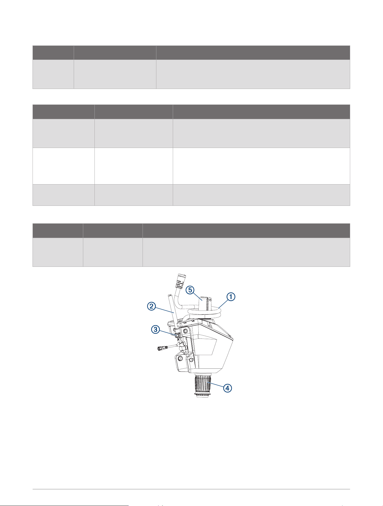
Description Service Kit Number Notes
Steering System S00-01000-80
Assembled steering system with power cable, coil cable,
depth limiter and depth-adjustment collar.
Removing the Steering System from the Mount, page14
Propeller Drive and
Shaft
50 in. model:
S11-06583-30
57 in. model:
S11-06583-31
Assembled shaft with propeller drive and GT56UHD trans
ducer. Does not include shaft cap.
Removing the Shaft, page23
Shaft Cap S00-01000-83
Complete shaft cap, including GPS module and hardware.
Removing the Shaft Cap, page22
Steering System Service Kits
Description Service Kit Number Notes
Steering System S00-01000-80
Assembled steering system with power cable, coil cable, depth limiter
and depth-adjustment collar.
Removing the Steering System from the Mount, page14
2 Service Kits
Description Service Kit Number
Coil Cable S00-01000-76
Power Cable S00-01000-22
Power Cable Clamp S00-01100-46
Depth Adjustment Collar S00-01000-75
Depth Limiter S00-01000-77
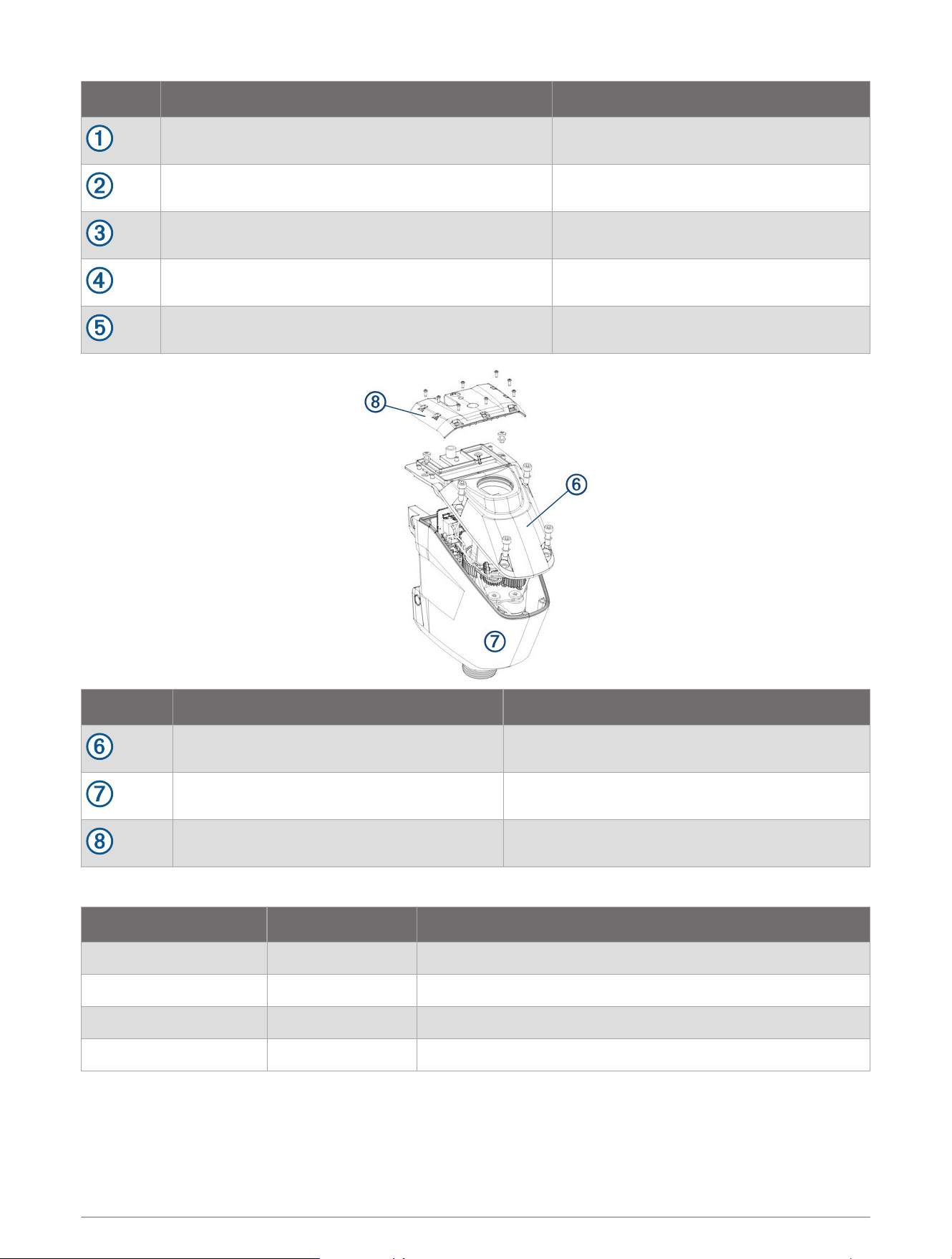
Description Service Kit Number
Top Housing S00-01000-15
Bottom Housing S00-01000-16
Electronics Cover S00-01000-78
Internal Components
Description Service Kit Number Notes
PCB S12-04968-00 Replacing the PCB, page59
Steering Position Sensor S00-01000-79 Replacing the Steering Position Sensor, page65
Shaft Carrier S00-01000-49 Removing the Steering Servo Motor and Shaft Carrier, page62
Steering Motor S00-01000-50 Removing the Steering Servo Motor and Shaft Carrier, page62
Service Kits 3

Propeller Drive and Shaft Service Kits
Description Service Kit Number Notes
Propeller Drive and
Shaft
50 in. model: S11-06583-30
57 in. model: S11-06583-31
Assembled shaft with propeller drive and GT56UHD
transducer. Does not include shaft cap.
Removing the Shaft, page23
Propeller Drive and Shaft Parts
Description Service Kit Number Notes
Propeller Drive
Motor
50 in. model: S00-01000-70
57 in. model: S00-01000-71
Includes o-rings, screws, washers and cable ties for the
propeller drive motor.
Removing the Propeller Drive Motor, page25
Shaft
50 in. model: S00-01000-72
57 in. model: S00-01000-73
Includes o-rings, screws, washers and cable ties for the
propeller drive motor.
Removing the Shaft, page23
Shaft Hardware S00-01000-35
Includes propeller drive motor mounting hardware, trans
ducer cable compression gland, spanner nut and wrench.
Shaft Cap
Description Service Kit Number Notes
Shaft Cap S00-01000-83
Complete shaft cap, including GPS module and hardware.
Removing the Shaft Cap, page22
Shaft Cap Parts
Description Service Kit Number Notes
Shaft Cap Top S11-06583-90
Includes GPS module.
Opening the Shaft Cap, page19
Shaft Cap Screws S00-01100-41 Opening the Shaft Cap, page19
Transducer Cable Grommet S00-01000-69 Removing the Transducer Cable, page21
4 Service Kits
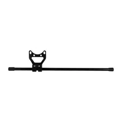
Mount
Description Service Kit Number Notes
Mount
50 in. model: S11-04653-20
57 in. model: S11-04653-21
Assembled mount with lower link, upper link, gas springs, display
panel and pull cable.
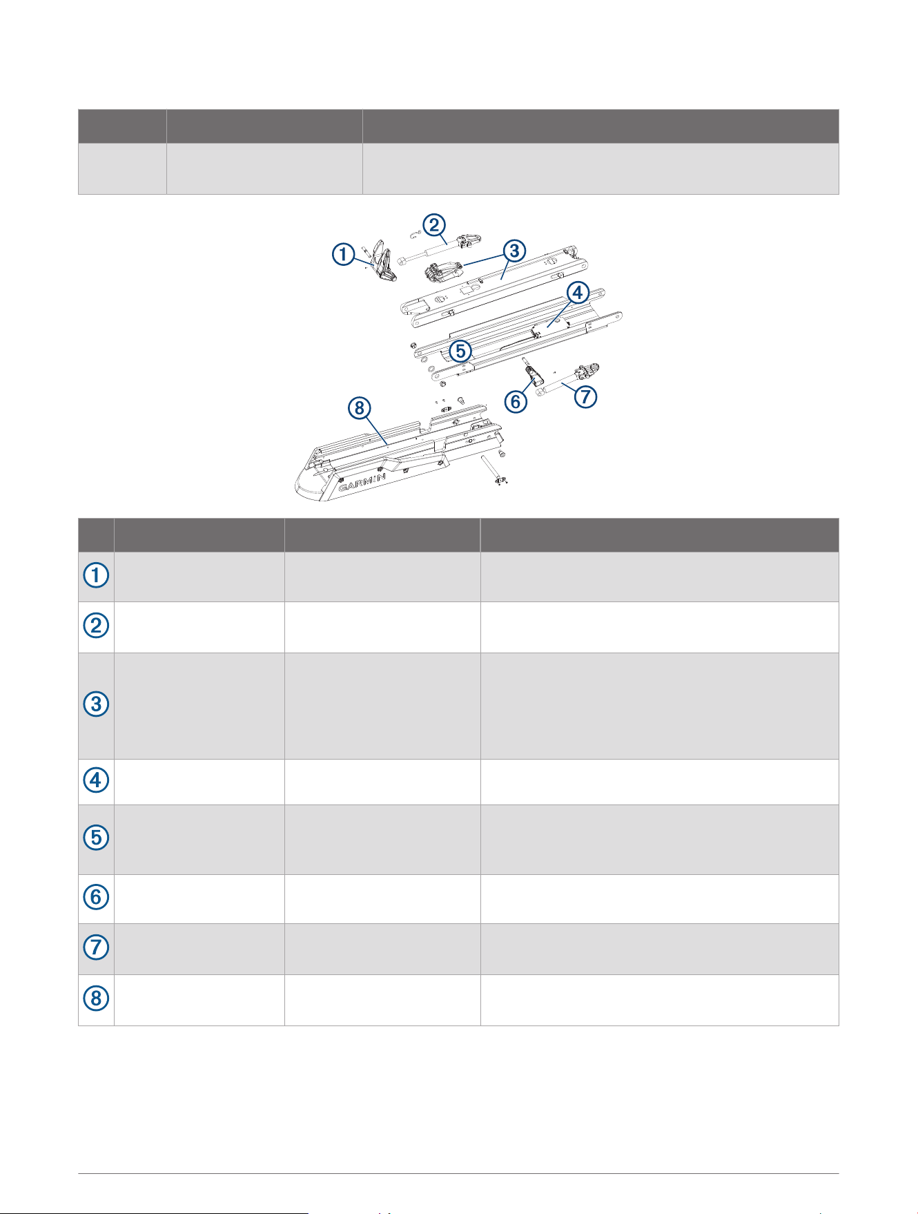
Description Service Kit Number Notes
Lower Gas Spring
Control Arm
S00-01000-18 Includes retaining screw.
Lower Gas Spring S00-01000-37
Includes pivot pin and screws.
Replacing the Lower Gas Spring, page44
Lower Link
50 in. model: S00-01000-81
57 in. model: S00-01000-82
Assembled lower link with pull cable and latch
mechanism. Does not include latch tension spring
and hook.
Removing the Lower Link from the Mount Base,
page52
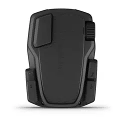
Display Panel S00-01000-74 Replacing the Display Panel, page50
Upper Link
50 in. model: S00-01000-03
57 in. model: S00-01000-08
Does not include display panel.
Removing the Upper Link from the Mount Base,
page51
Upper Gas Spring
Control Arm
S00-01000-17 Includes retaining screw.
Upper Gas Spring
50 in. model: S00-01000-38
57 in. model: S00-01000-40
Includes pivot pin and screws.
Replacing the Upper Gas Spring, page45
Mount Base
50 in. model: S00-01000-05
57 in. model: S00-01000-10
Includes mount shrouds, rails, bumper and stow
support.
Service Kits 5

Mount Hardware
Description Service Kit Number Notes
Gas Spring Screws S00-01000-25
Screws for securing the upper and lower gas springs to the
lower link.
Power Cable Brackets S00-01000-27
Brackets for securing the power and transducer cables to the
mount.
Deck Mounting Hardware S00-01000-24
1
/
4
–20 screws, nuts and washers for mounting the trolling
motor.
Latch Mechanism Parts
Description Service Kit Number Notes
Lower Link Internal
Components
50 in. model:
S00-01000-45
57 in. model:
S00-01000-11
Complete latch mechanism and pull cable guide.
Includes two sets of cotter pins. For the Force Pro trolling
motor, you should use the pins in bag A.
Replacing the Latch Mechanism in the Lower Link, page54
Cotter Pins S00-01000-58
Cotter pins for securing the latches and the pull cable to the
latch release rod.
Includes two sets of cotter pins. For the Force Pro trolling
motor, you should use the pins in bag A.
Tension Spring and
Spring Hook
S00-01658-00 Latch mechanism tension spring and S-hook.
Mount Base Parts
Description Service Kit Number Notes
Mount Rails
50 in. model: S00-01000-33
57 in. model: S00-01000-34
Replacing the Mount Rails, page56
Mount Shrouds S00-01000-14 Replacing the Mount Shrouds, page56
Mount Bumper S00-01000-19 Replacing the Mount Bumper, page57
Stow Support S00-01000-47 Replacing the Stow Support, page57
6 Service Kits

Other Service Kits
Description
Service Kit
Number
Notes
Hinge Pins S00-01000-20 Includes all hinge pins for the mount and steering system.
Hinge Pins and
Bushings
S00-01000-46
Includes all hinge pins and bushings for the mount and steering
system.
Steering System
Bushings
S00-01000-30
Bushings for the upper and lower link hinge pins on the steering
system.
Includes three sets of bushings. For the Force Pro trolling motor,
you should use the bushings marked 12-3 and 15-3.
Pull Handle and
Hardware
S00-01000-26 Installing the Handle on the Pull Cable, page11
Stabilizer Bumpers S00-01000-62
See the Stabilizer Installation Instructions at garmin.com
/manuals/force_pro_trolling_motor.
Propeller Hardware S00-01000-28
Includes propeller nut, washers, propeller shaft pin and sacrificial
anode.
Replacing the Propeller, page8
Spanner Wrench S00-01000-44
Required for removing and installing the transducer cable
compression nut on the bottom of the shaft.
Removing the Transducer Cable from the Shaft, page26
Propeller Drive Motor
Power Connector Set
Screws
S00-01100-31 Disconnecting the Cables, page20
Service Kits 7
Service Procedures
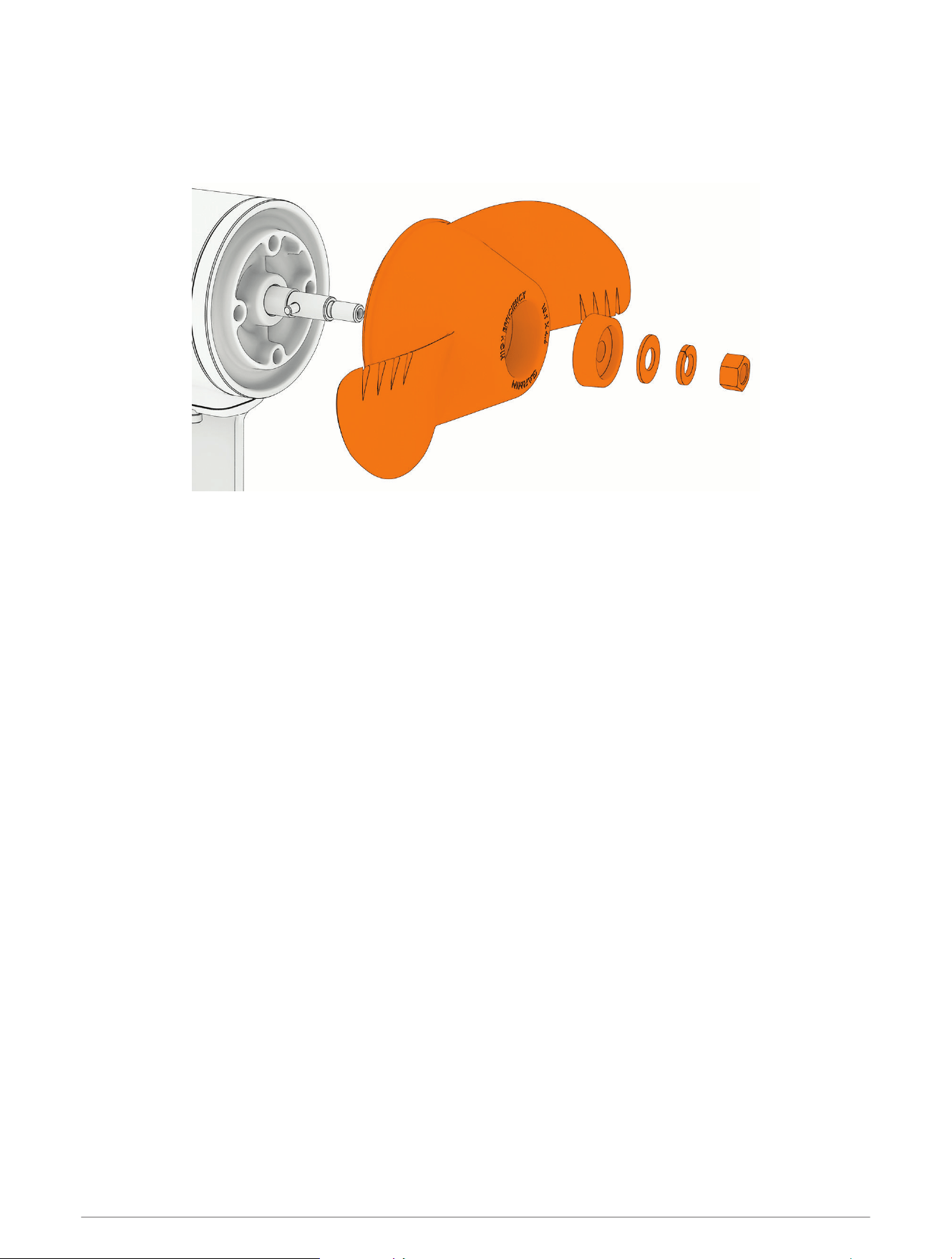
Replacing the Propeller
1 Using a
9
/
16
in (15mm) socket, remove the nut that secures the propeller.
2 Remove the propeller and set aside the lock washer, flat washer and sacrificial anode.
3 Make sure the pin in the propeller motor shaft is in place, and replace it if necessary.
4 Install the new propeller.
5 Place the anode, flat washer, lock washer, and nut back on the propeller drive shaft.
6 Using a
9
/
16
in (15mm) socket, tighten the nut to 16.27N-m (12lbf-ft) to secure the propeller.
8 Service Procedures
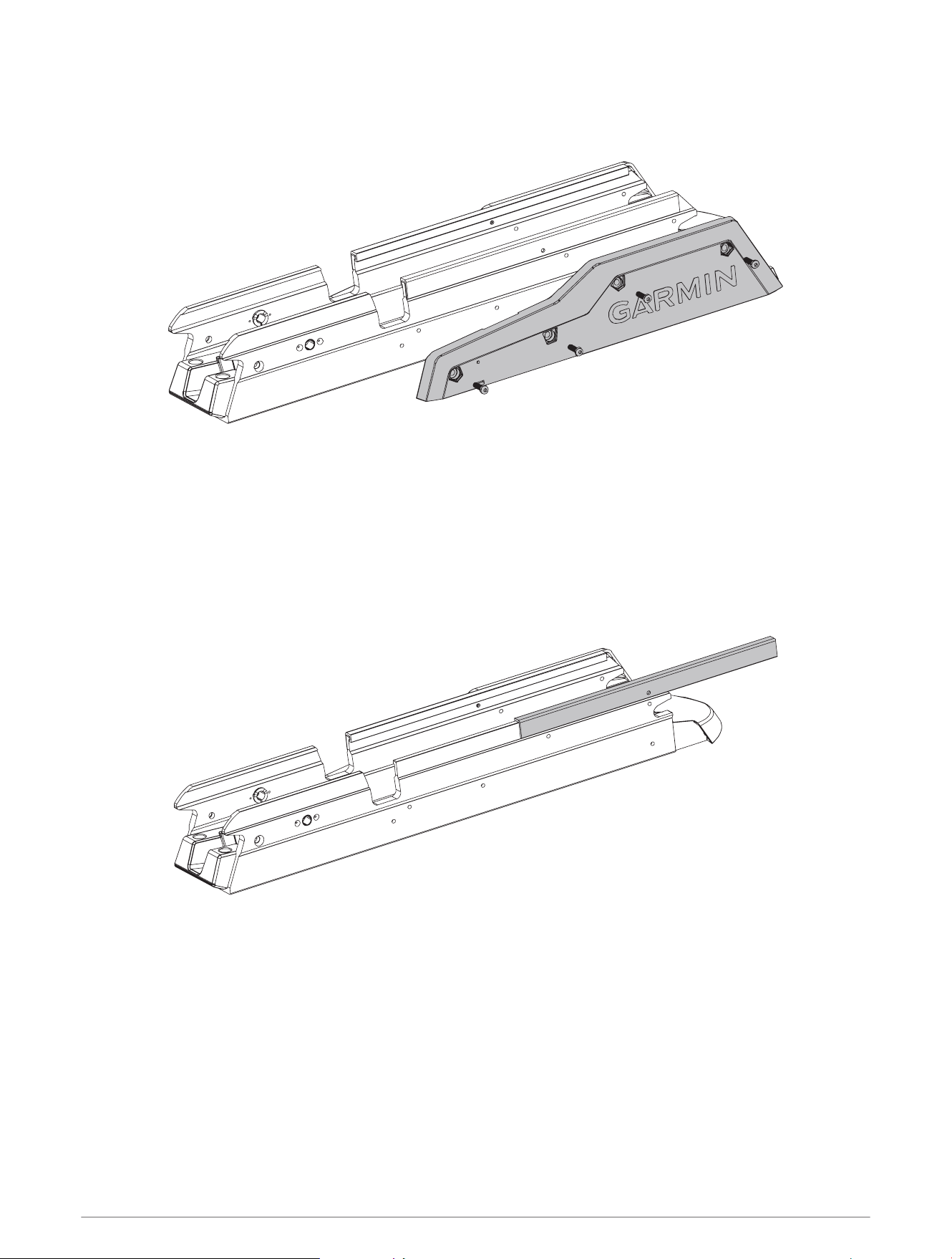
Replacing the Pull Cable
Removing the Pull Cable Handle
1 Transition the motor to the stowed position, and secure the safety strap.
CAUTION
You must keep the motor in the stowed position with the safety strap secured until you have finished servicing
your motor. If the mount is not securely locked in the stowed position while you work, it may shift and crush
your hands or fingers.
2 Using a #1 Phillips screwdriver, loosen the two screws that secure the top of the handle.
3 Push the pull cable up from the bottom of the handle, and remove the R-pin .
4 Pull the cable out through the washer and the bottom of the handle.
Removing the Pull Cable
Before you can remove the pull cable, you must remove the pull cable handle (Removing the Pull Cable Handle,
page9).
1 Locate the access hole on the lower link, near the depth adjustment collar.
2 Using needle-nose pliers, remove the R-pin that secures the pull cable to the locking mechanism.
3 Remove the end of the pull cable through the access hole, and pull to remove the rest of the cable from the
steering system housing.
Service Procedures 9
Installing a New Pull Cable
Before you can install a new pull cable, you must remove the existing pull cable (Removing the Pull Cable,
page9).
CAUTION
You must keep the motor in the stowed position with the safety strap secured until you have finished servicing
your motor. If the mount is not securely locked in the stowed position while you work, it may shift and crush
your hands or fingers.
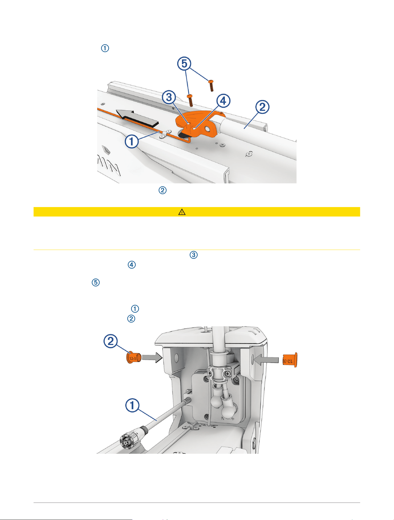
1 Feed the smaller end of the new pull cable into the access hole on the mount base and up through the
steering system.
2 Using your hand through the underside of the motor, guide the small end of the pull cable under the pivot pin
and out through the hole on the top of the steering system .
3 Pull the cable through until the larger end passes through the access hole.
4 Place the larger end of the cable over the stud in the access hole.
5 If necessary, rotate the cable to align the hole on the end of the cable with the hole on the stud, and push the
R-pin through.
TIP: You can use needle-nose pliers to push the R-pin, if necessary.
10 Service Procedures
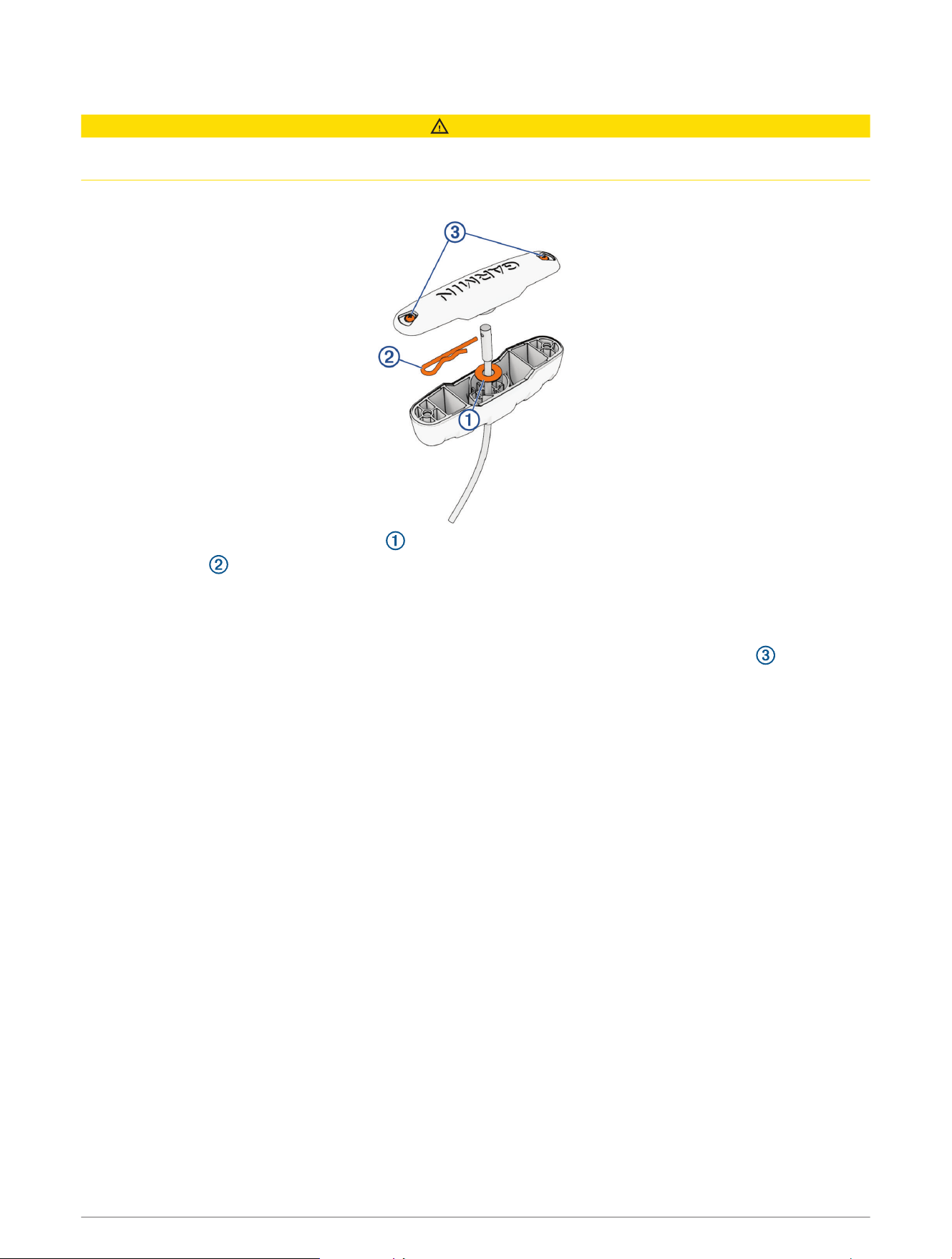
Installing the Handle on the Pull Cable
CAUTION
You must install the included R-pin in the handle. Using an inadequate R-pin in the handle may cause a failure of
the handle potentially leading to personal injury.
1 Insert the pull cable through the handle.
2 Insert the pull cable through the washer .
3 Push the R-pin through the hole on the end of the pull cable.
4 Pull the cable down so that the washer and R-pin rest fully in the handle.
NOTE: If the washer and the R-pin are not fully seated in the handle, you will not be able to install the handle
cover.
5 Place the handle cover on the handle and, using a #1 Phillips screwdriver, tighten the screws .
Service Procedures 11
Removing the Power and Transducer Cables From the Mount
1 Disconnect the motor from the power source.
2 Remove the power-cable plug, if necessary.
NOTE: If you installed the power-cable accessory plug sold by Garmin, you should use a
3
/
32
in. hex bit or
wrench and a #1 Phillips screwdriver to remove it.
3 Using a #1 Phillips screwdriver, remove the single screw that secures the cable clamp to the shroud.
4 Using a 3mm hex bit or wrench, remove the screws that secure the two cable clamps to the upper link.
5 Pull the power cable out of the channel along the side of the mount.
6 Pull the transducer cable out of the channel along the side of the mount.
12 Service Procedures
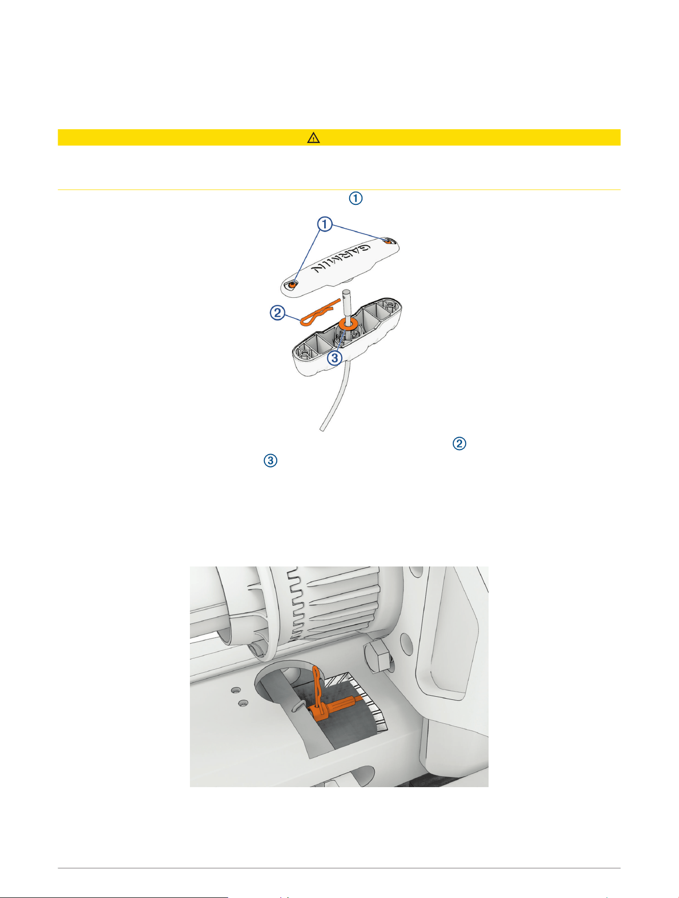
Routing the Power and Transducer Cables Through the Mount
After you have installed a replacement power cable, transducer, shaft, or propeller drive motor, you should route
the power and transducer cables through the mount.
NOTICE
To avoid damaging the power and transducer cables when deploying and stowing the trolling motor and to
avoid interference with the GPS and heading sensors in the motor, you must route the cables through the right
(starboard) side of the mount and secure them using the included hardware. You must not route the power
cable through the left (port) side of the mount, and it is not possible to install the included brackets on the left
(port) side. The left (port) side is reserved for additional accessories or transducer cables that you may install in
the future.
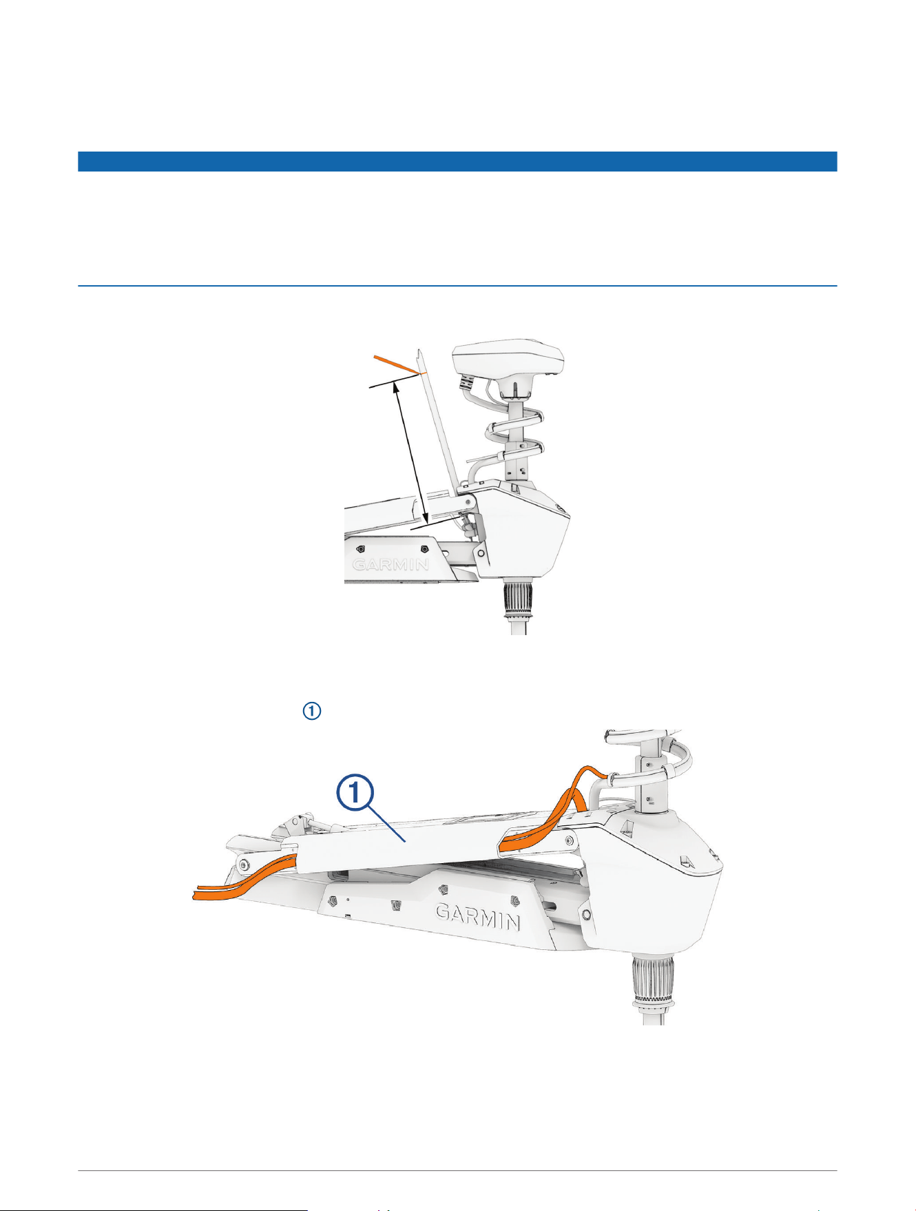
1 Measure approximately 40cm (16in.) on the power cable from where it connects to the steering system, and
look for the mark on the cable applied at the factory.
2 If you do not see a mark on the cable, or if the mark is not approximately 40cm (16in.) from the connection,
make a mark with a marker or tape.
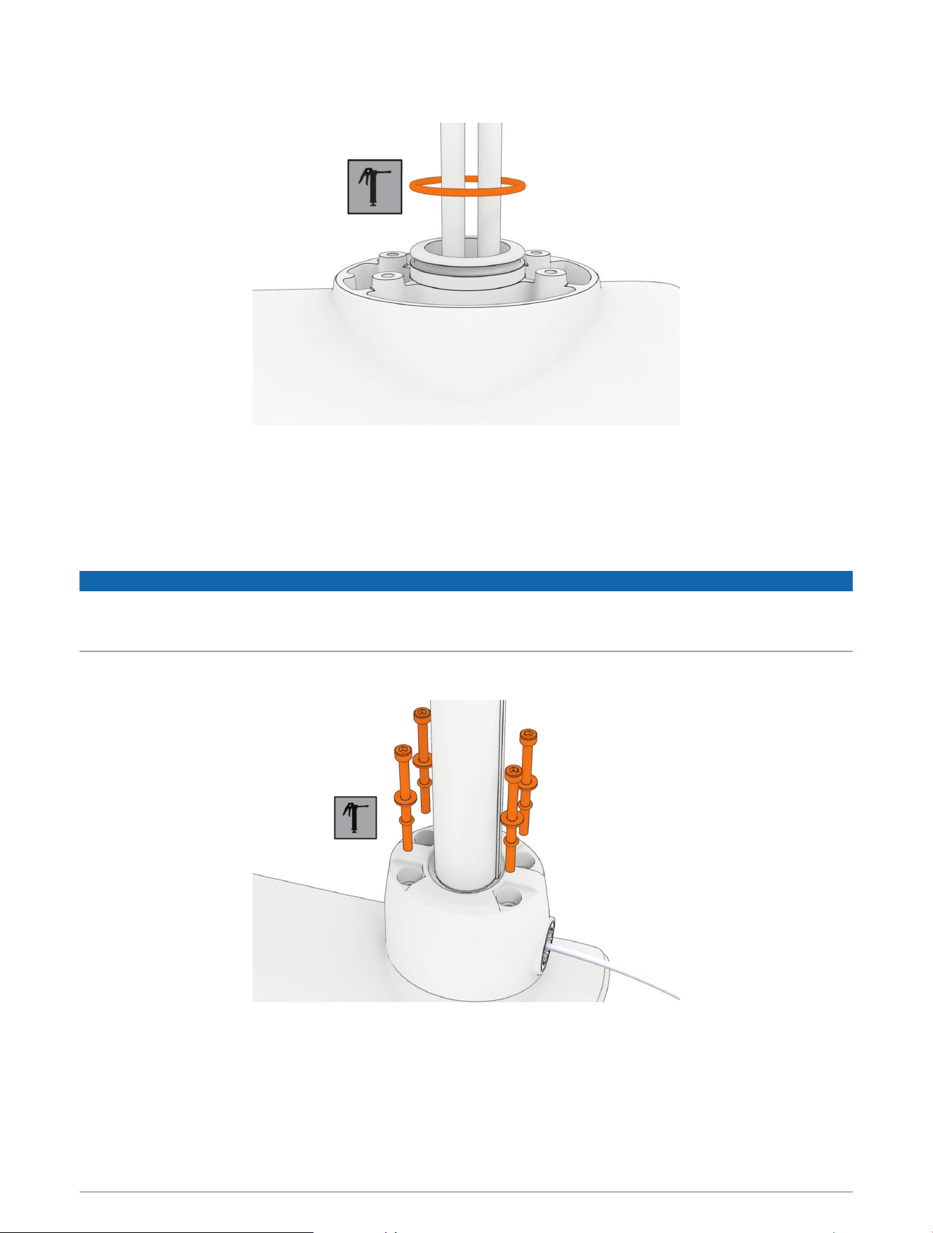
3 With the motor in the deployed position, route the transducer cable through the channel along the right
(starboard) side of the mount .
TIP: To determine the right (starboard) side of the mount, stand in a location where you can read the
information on the display panel.
4 Route the power cable through the channel above the transducer cable.
Service Procedures 13
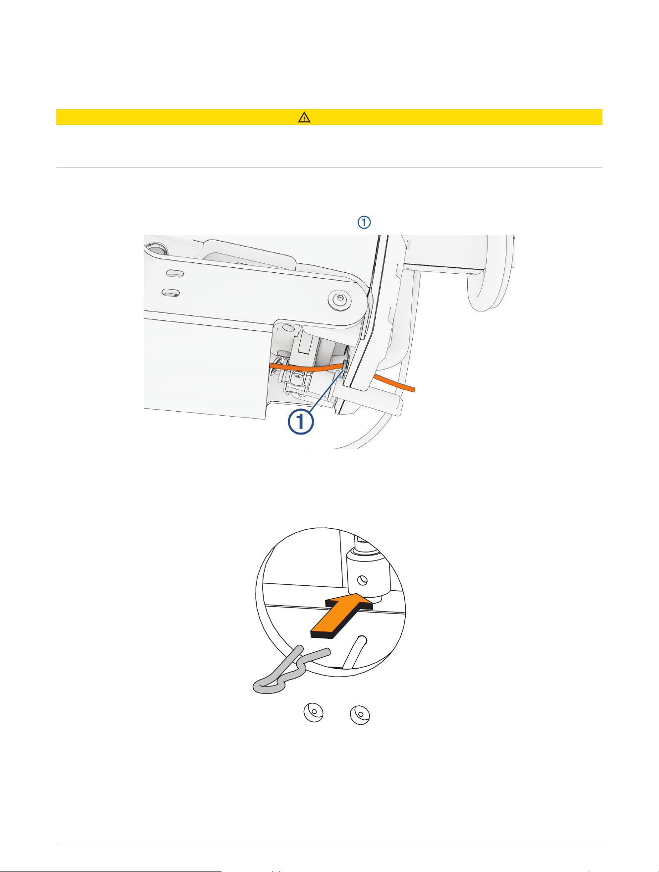
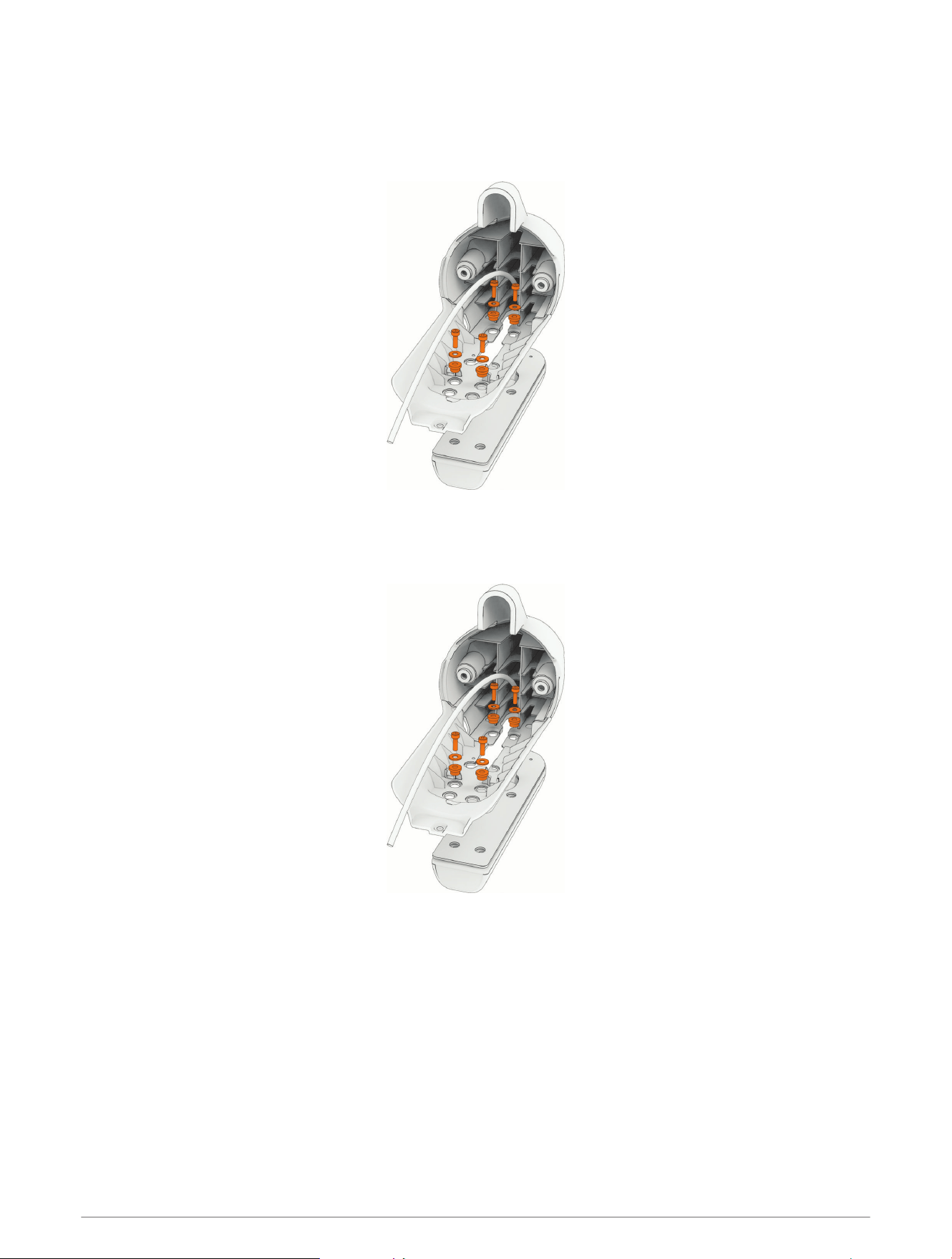
5 Using the pull cable, carefully lift the motor from the deployed position to the stowed position.
NOTICE
You must secure the cables to the mount with the motor in the stowed position. If you complete this procedure
with the motor in the deployed position, the cables are not at their fully extended length, and the added stress
may damage the cables during use.
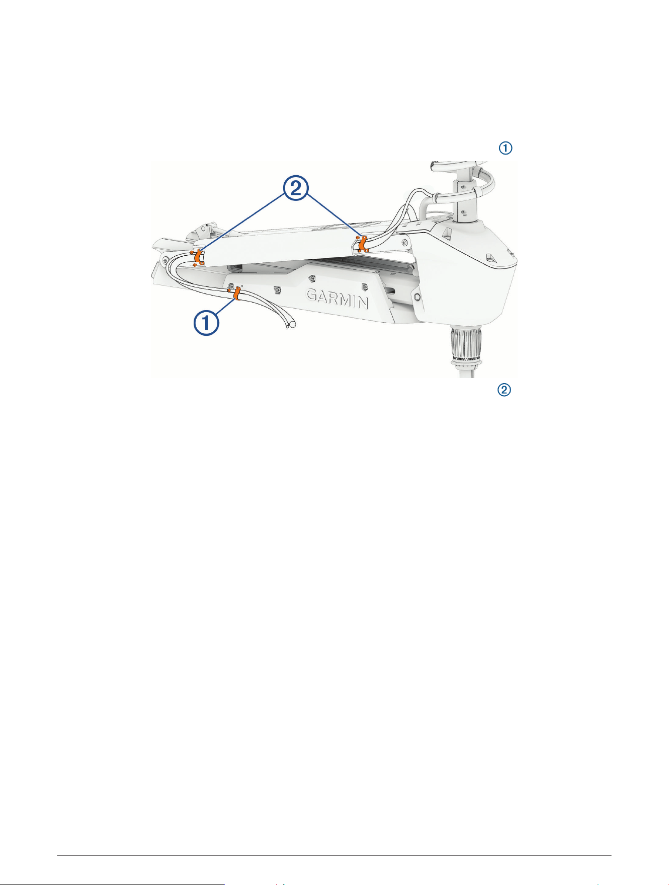
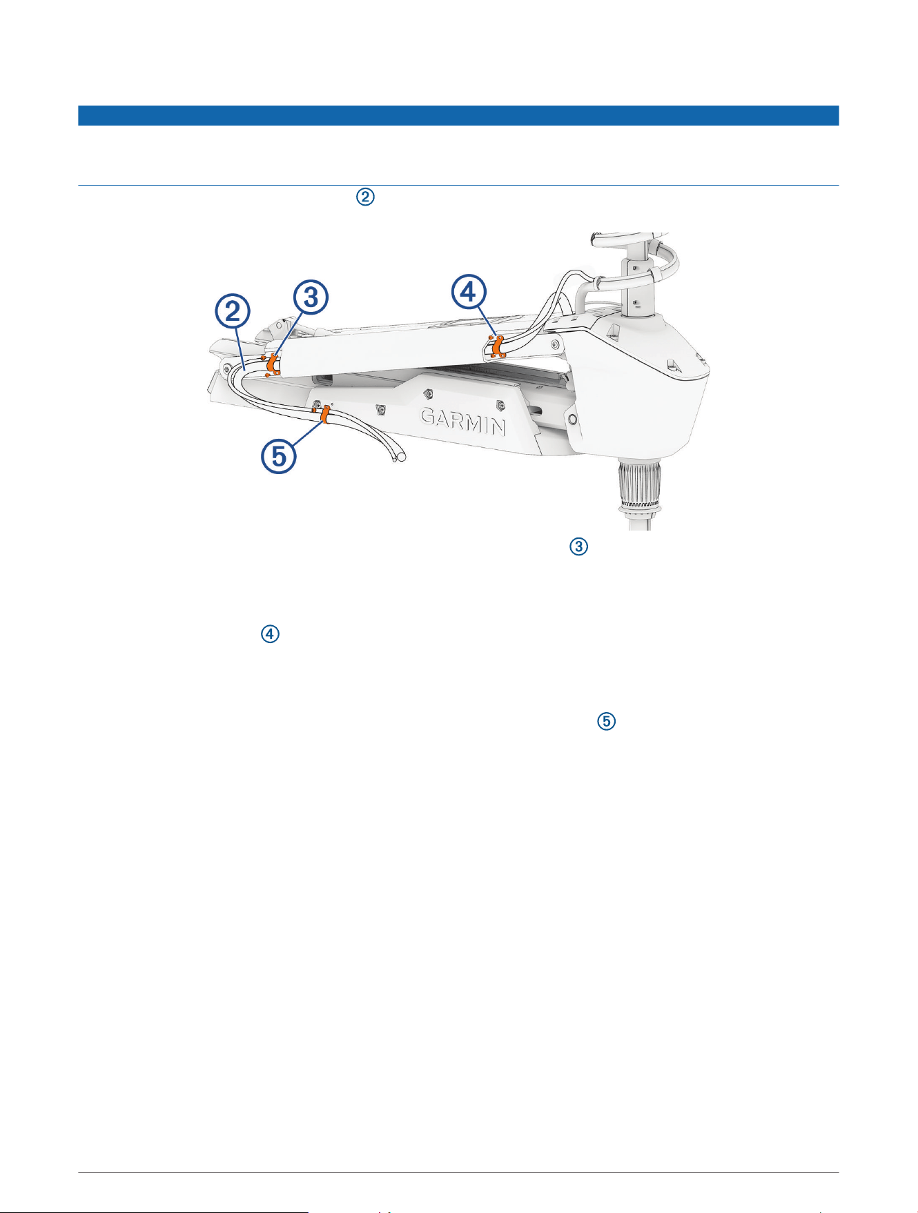
6 Leaving a rounded bend in the cables , hold them against the side of the mount where they enter the
channel.
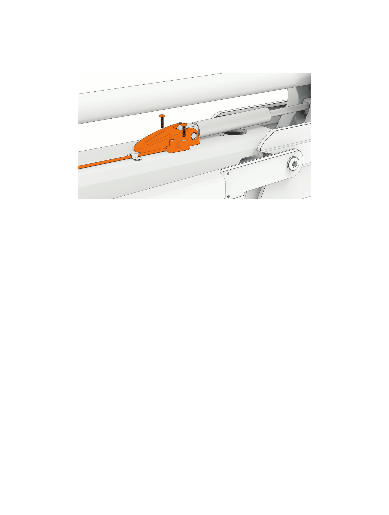
7 At the marked location on the power cable, place one of the brackets that have two screw holes over the
cables and against the mount, aligning the holes on the bracket with the holes on the mount.
8 Using a 3mm hex bit or wrench, secure the bracket to the mount using two screws.
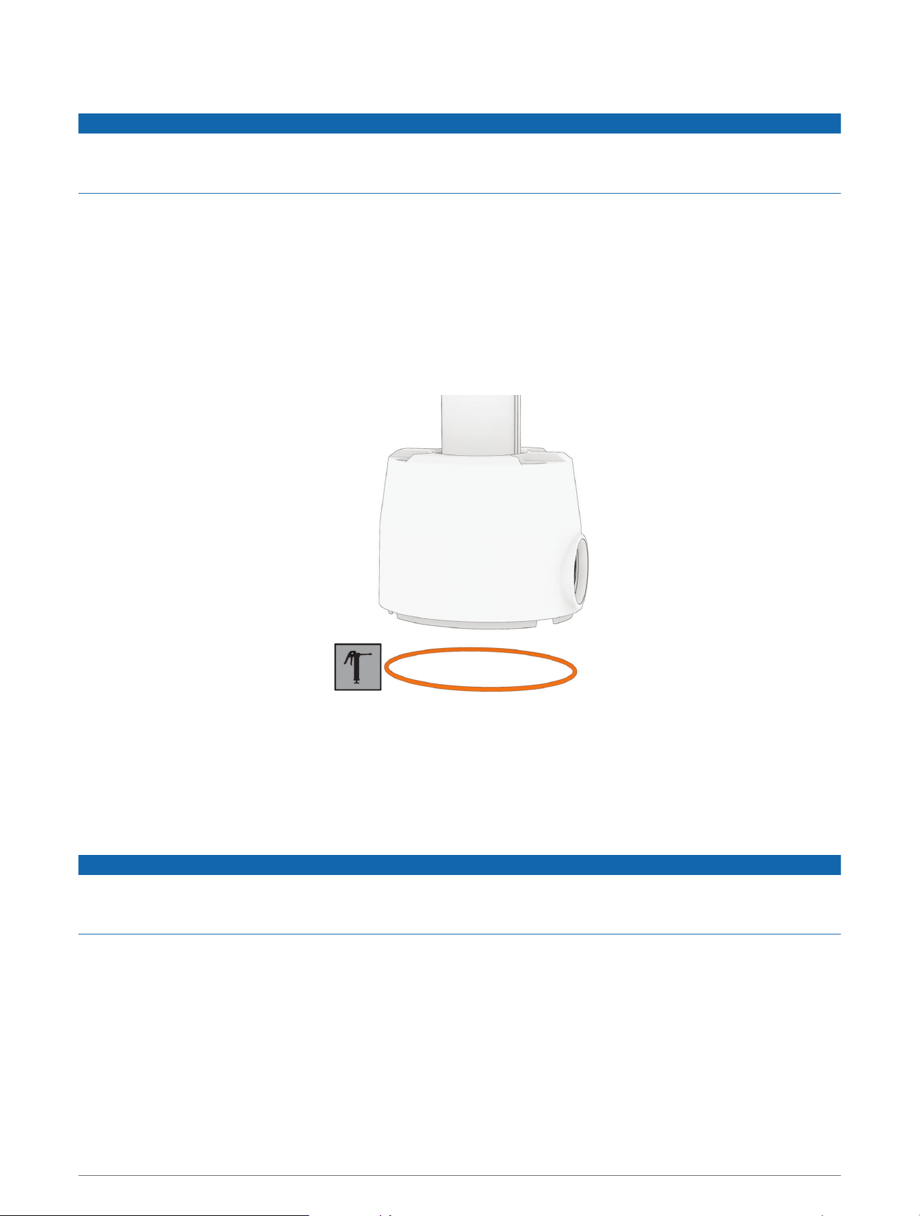
9 Hold the cables against the bottom of the mount where they exit the channel.
10 Place the other bracket that has two screw holes over the cables and against the mount, aligning the
holes on the bracket with the holes on the mount.
11 Using a 3mm hex bit or wrench, secure the bracket to the mount using two screws.
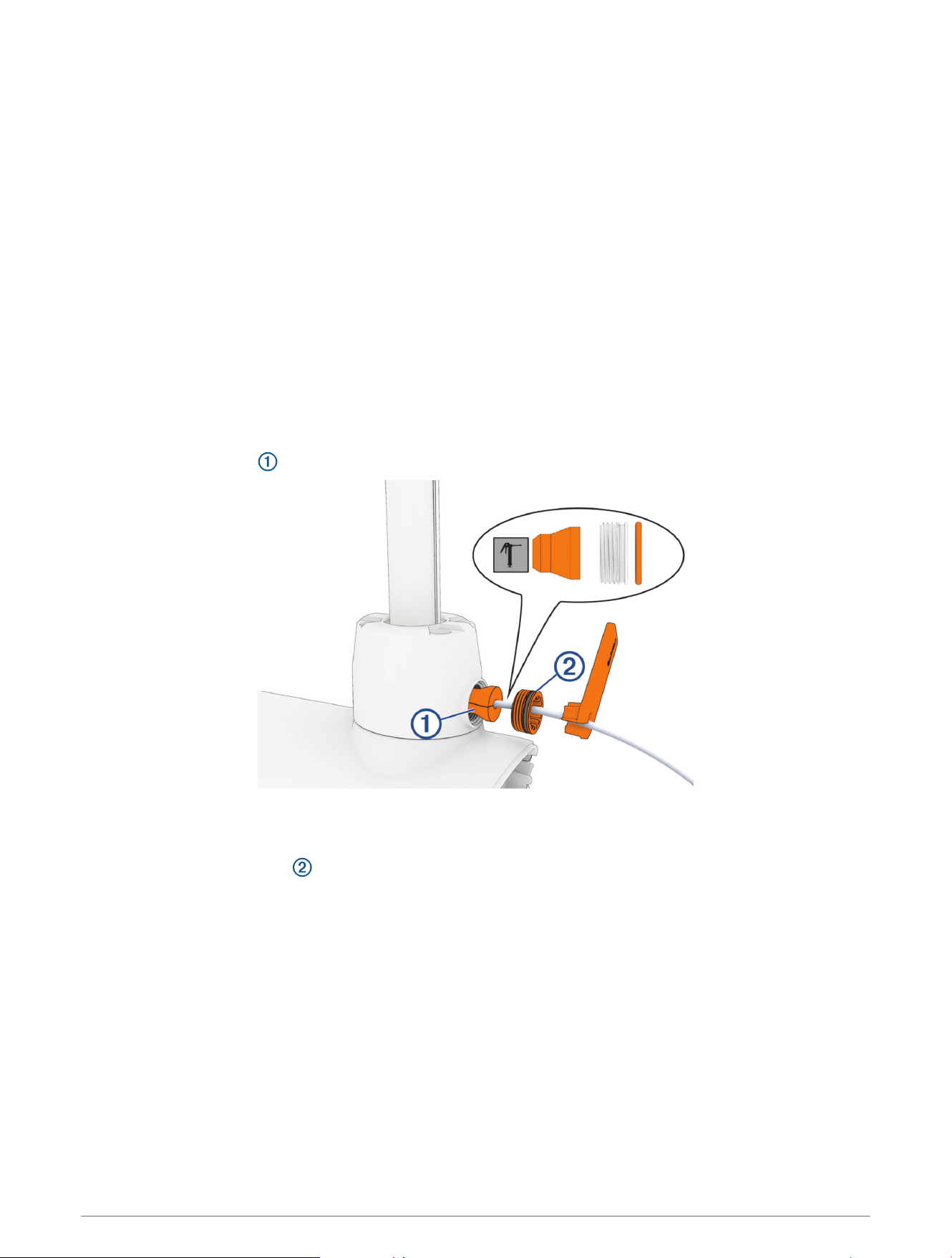
12 Hold the cables against the plastic portion of the mount base, close to the boat deck.
13 Insert the lower tab on the remaining bracket into a slot below the cables , and rotate the bracket toward
the mount base to hold the cables.
14 Using a #1 Phillips screwdriver, secure the upper tab of the bracket to the mount base using a single screw.
Removing the Steering System from the Mount
Before you can remove the steering system from the mount, you must remove the power and transducer cables
from the mount (Removing the Power and Transducer Cables From the Mount, page12).
1 Disconnect the lower gas spring (Disconnecting the Lower Gas Spring, page15).
2 Disconnect the upper link of the mount (Disconnecting the Upper Link from the Steering System, page16).
3 Disconnect the upper gas spring (Disconnecting the Upper Gas Spring, page17).
4 Disconnect the lower link of the mount (Disconnecting the Lower Link from the Steering System, page18).
14 Service Procedures
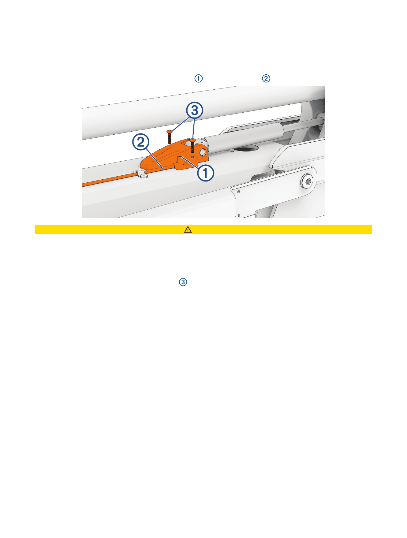
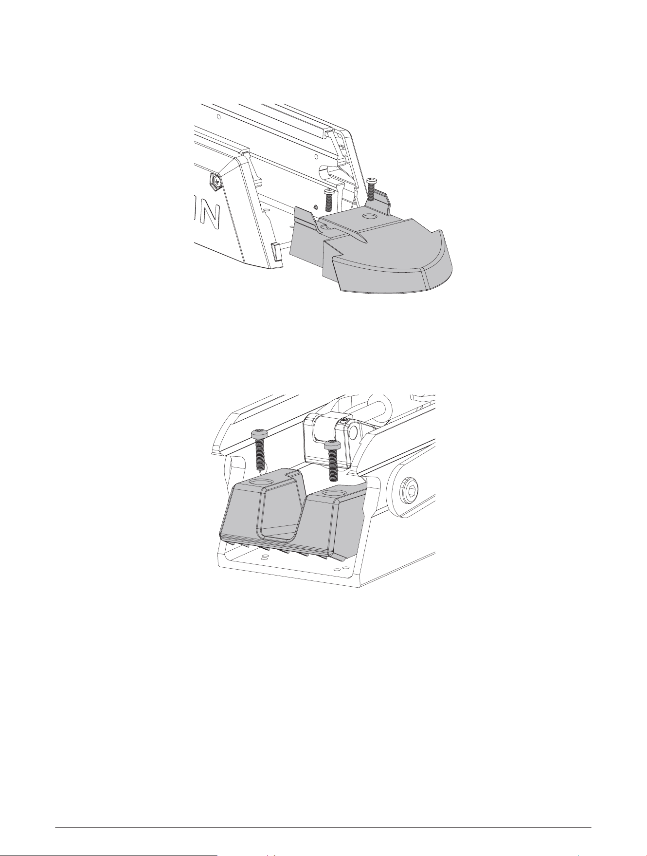
Disconnecting the Lower Gas Spring
1 Place the trolling motor in the stowed position.
2 Using a #2 Phillips screwdriver, remove the screws that secure the lower gas spring clevis to the lower link of
the mount.
3 Lift the lower gas spring clevis off of the safety rod.
Service Procedures 15
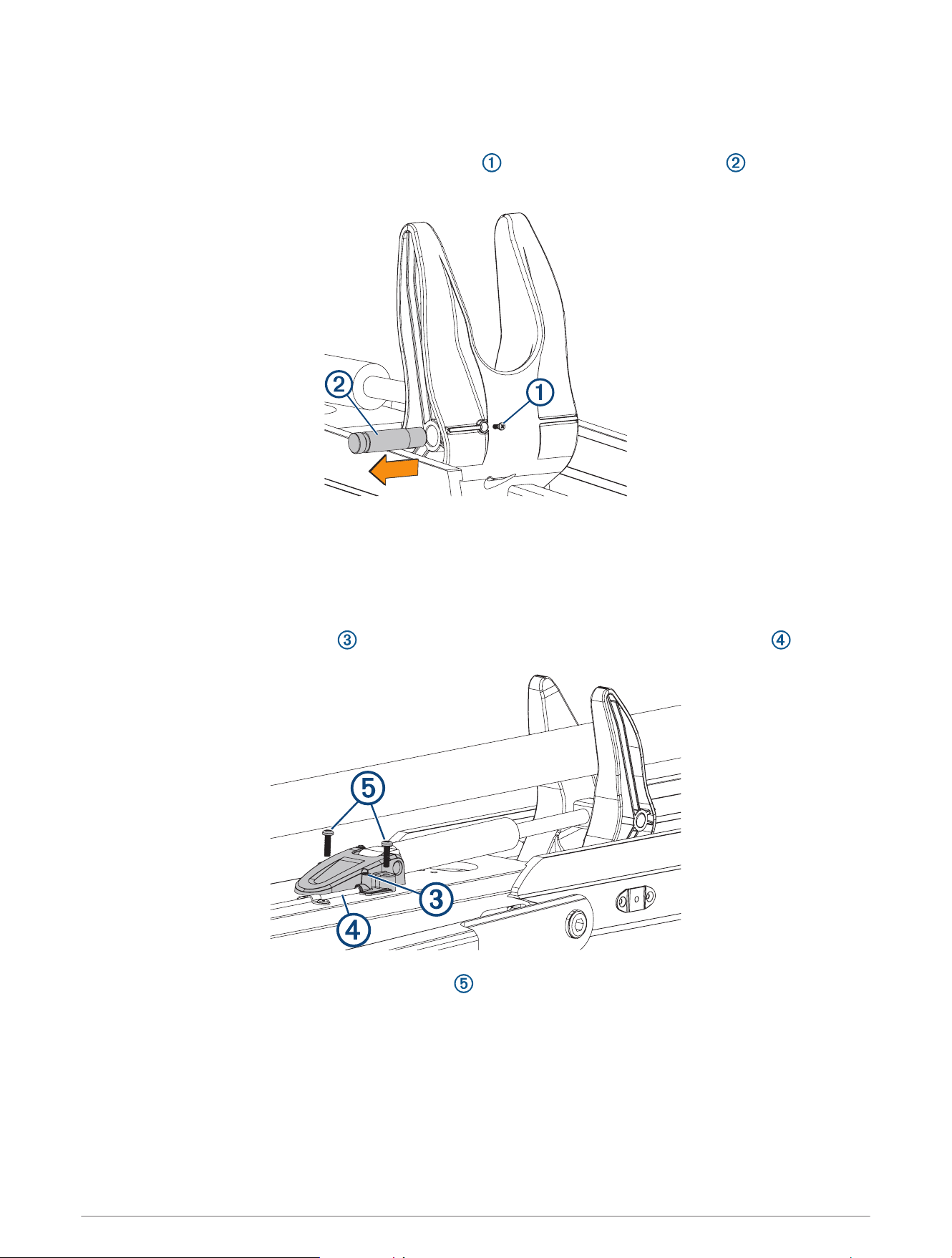
Disconnecting the Upper Link from the Steering System
Before you can disconnect the upper link of the mount, you must remove the power and transducer cables from
the mount (Removing the Power and Transducer Cables From the Mount, page12).
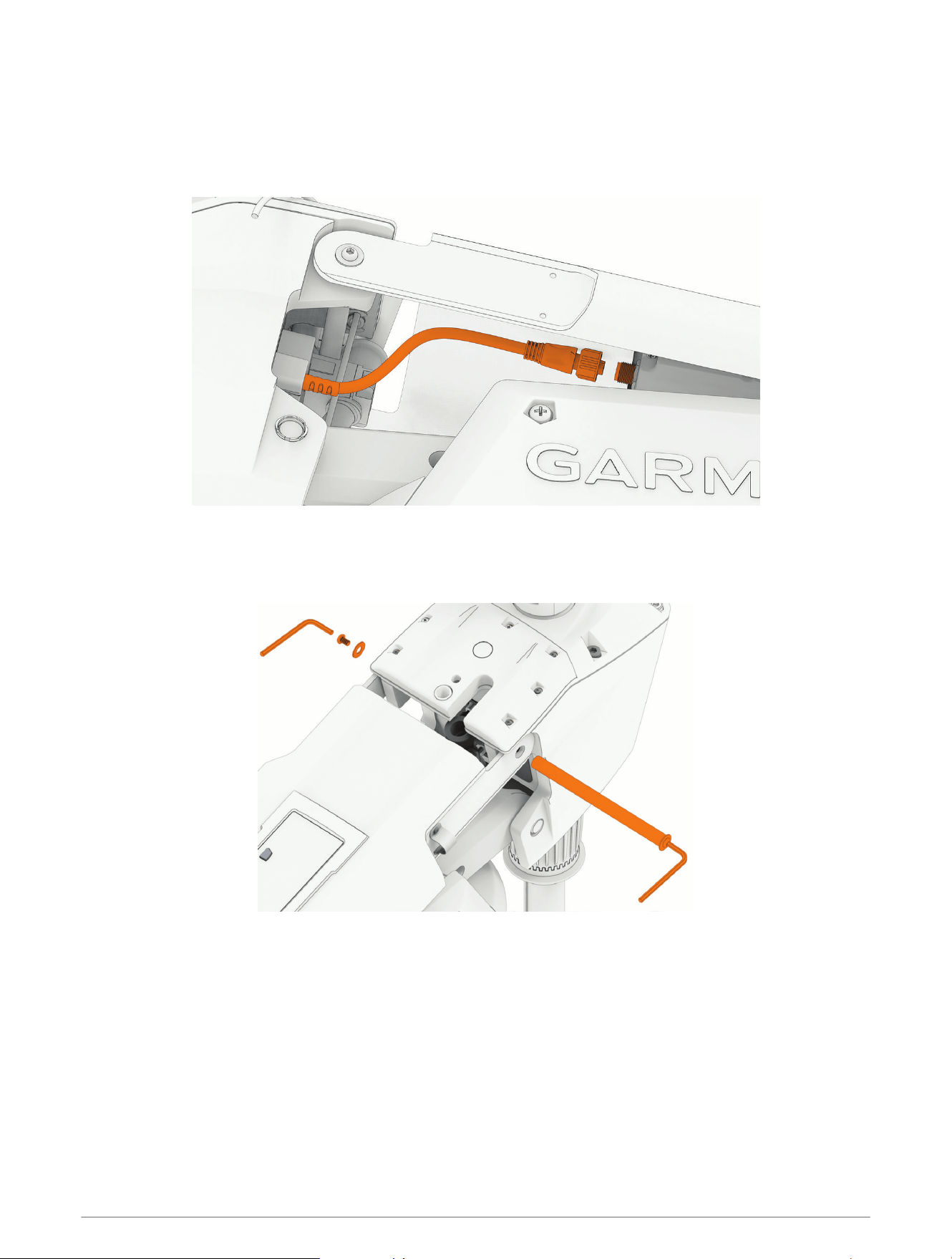
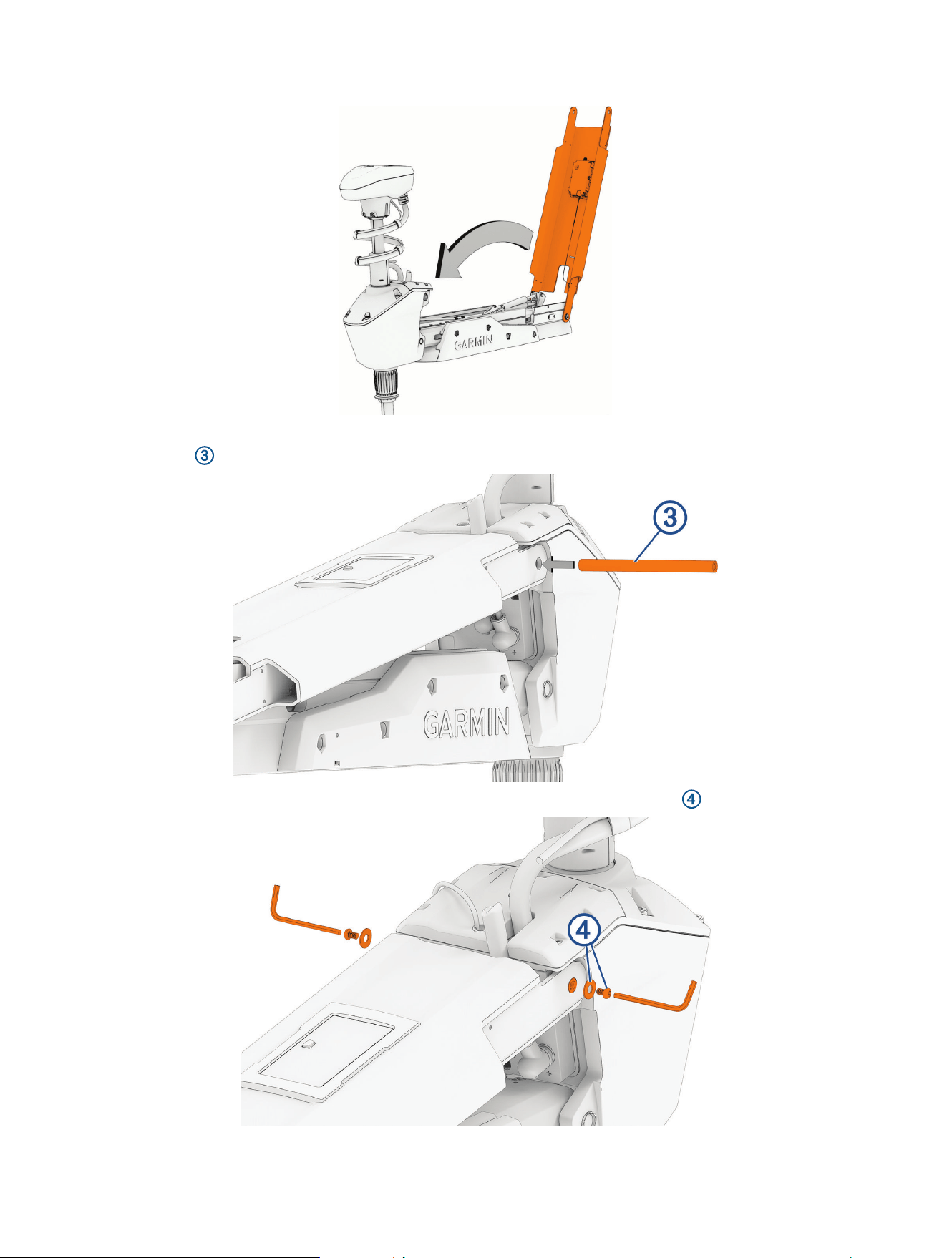
1 With the motor in the deployed position, disconnect the cable from the display panel on the upper link of the
mount.
2 Using a 4mm hex bit or wrench, remove a screw and washer from one side of the upper pin on the steering
system.
TIP: You should use another 4mm hex wrench on the other end of the pin to prevent it rotating while you
remove the screw.
3 Remove the upper pin from the steering system.
4 Pivot the upper link away from the steering system.
16 Service Procedures
Disconnecting the Upper Gas Spring
Before you can disconnect the upper gas spring, you must disconnect the upper link of the mount
(Disconnecting the Upper Link from the Steering System, page16) and disconnect the lower gas spring
(Disconnecting the Lower Gas Spring, page15).
1 Using a #2 Phillips screwdriver, remove the two screws that secure the lower gas spring clevis to the lower
link of the mount.
2 Lift the upper gas spring clevis off of the safety rod.
Service Procedures 17
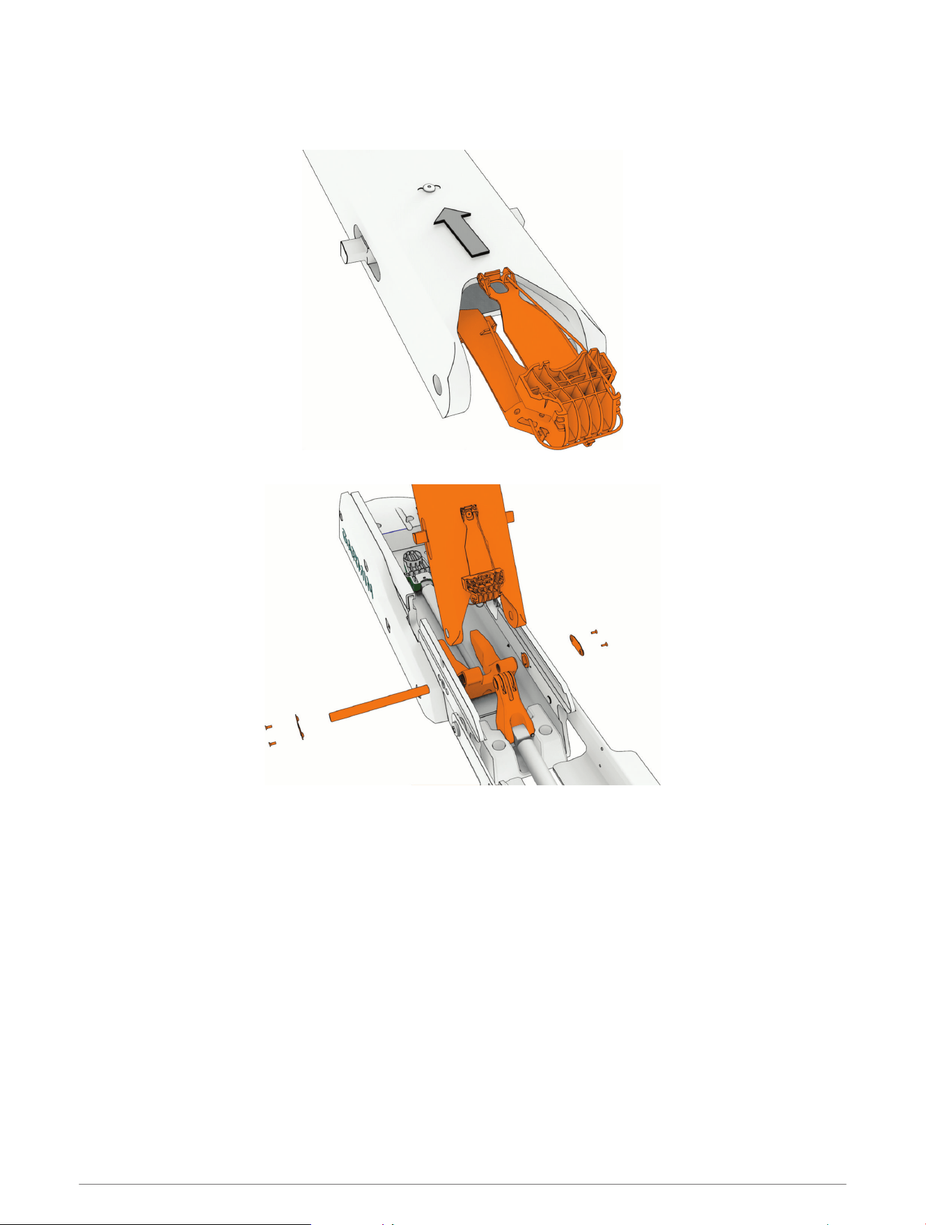
Disconnecting the Lower Link from the Steering System
WARNING
You must disconnect the lower gas spring (Disconnecting the Lower Gas Spring, page15) and the upper gas
spring (Disconnecting the Upper Gas Spring, page17) before disconnecting the steering system from the lower
link of the mount. Removing the steering system without disconnecting the gas springs creates a situation in
which, if the latch is accidentally released, the lower link of the mount will move suddenly with great force,
potentially leading to severe injury.
CAUTION
The lower pin is the final piece connecting the steering system to the mount. When you remove the pin, the
steering system and the drive motor and shaft, if they are still installed, may fall causing personal injury or
damage to the motor. Make sure that you support the weight of the steering system before you remove the pin.
To avoid personal injury or damage to the motor, this procedure should be performed with two people.
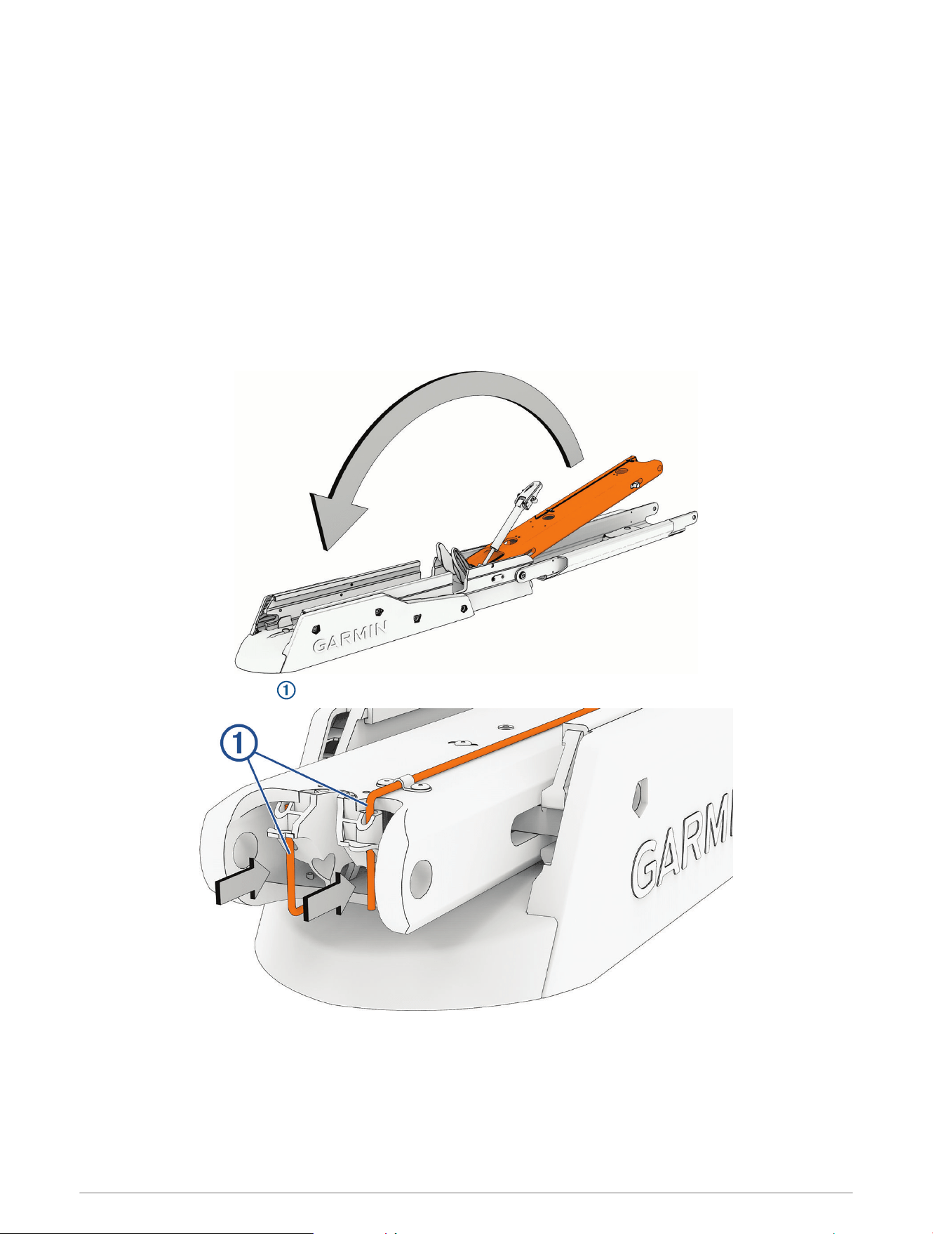
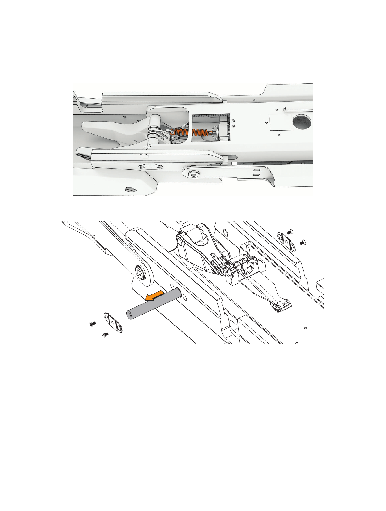
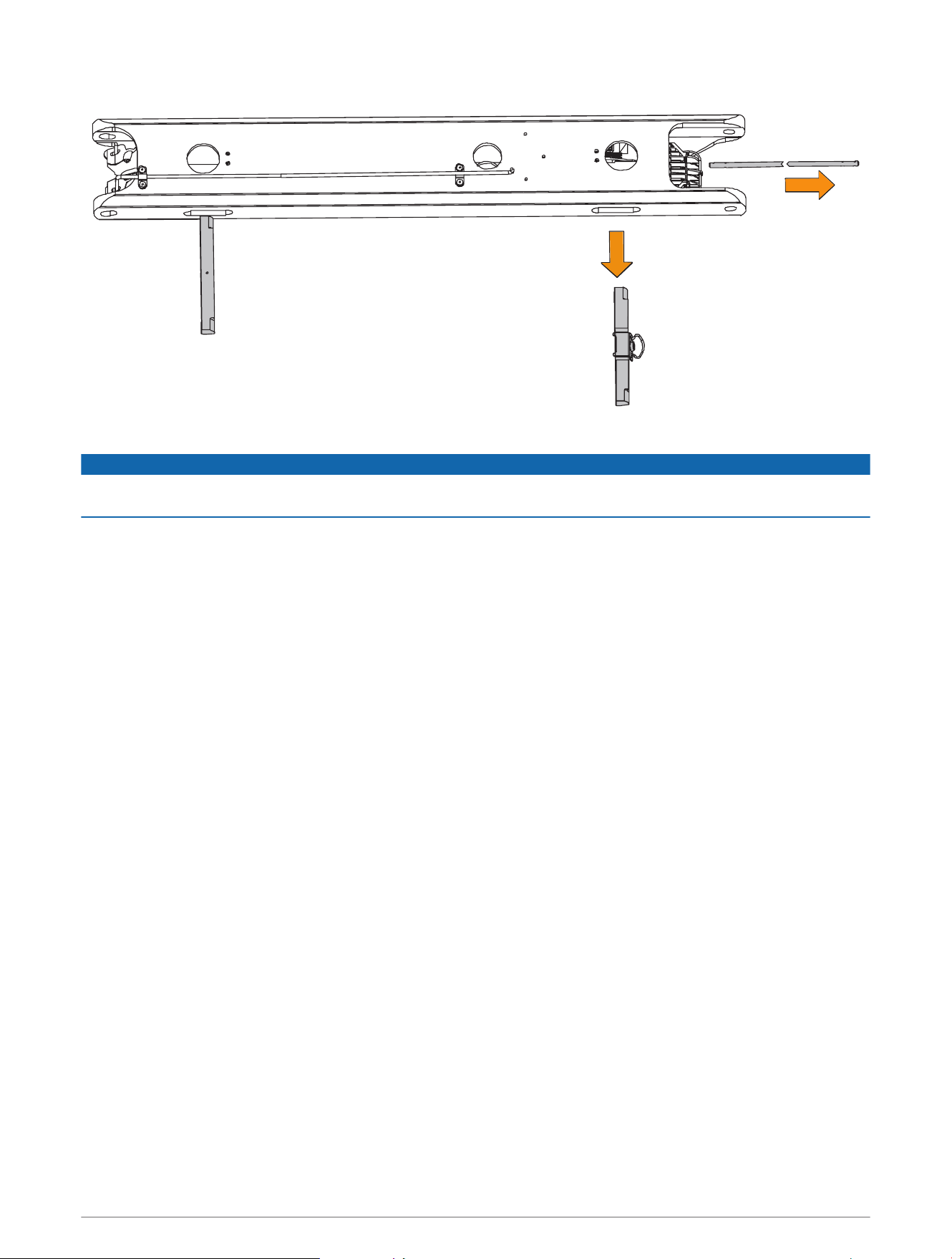
1 Remove the pull handle from the cable (Removing the Pull Cable Handle, page9).
2 Pull the on the other end of the cable until it comes completely through the hole in the steering system
housing.
TIP: You should tape the end of the cable to keep it from interfering when you remove the steering system
from the mount.
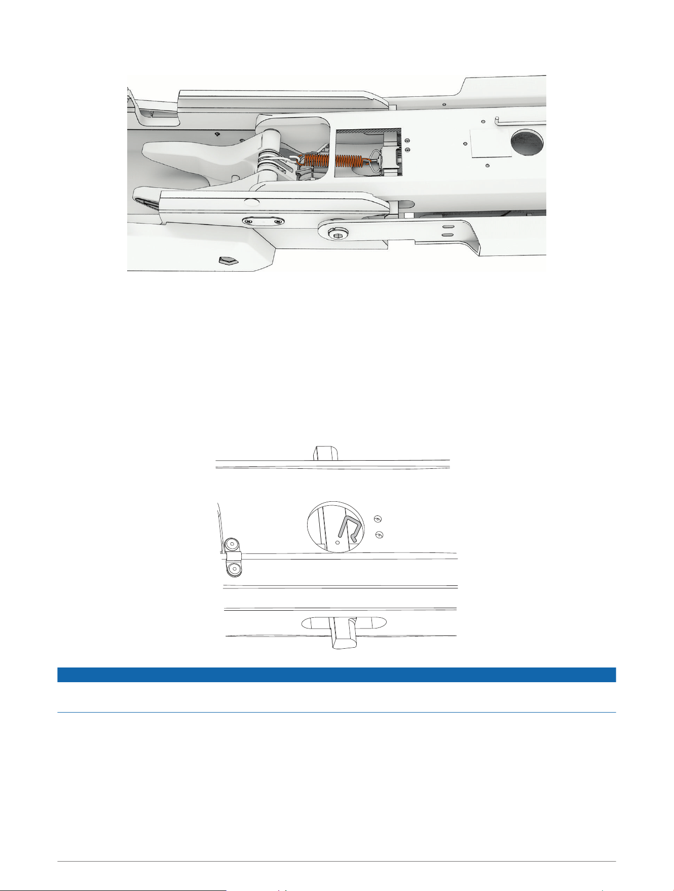
3 Slide the safety rods away from the steering system to release the lower pivot pin.
NOTE: The two safety rods don't need to move very far to release the lower pivot pin. If either gas spring is
still connected to the lower link, however, the safety rods lock the lower pivot pin in place, and it cannot be
removed.
4 While supporting the weight of the steering system, push the lower pin out from one side, and pull in from the
other side to remove it completely.
Removing the Shaft from the Steering System
Before you can remove the shaft from the steering system, you must remove the transducer cable from the
mount, if applicable (Removing the Power and Transducer Cables From the Mount, page12).
1 Disconnect the motor from the power source.
2 Open the shaft cap (Opening the Shaft Cap, page19).
3 Disconnect the cables in the shaft cap (Disconnecting the Cables, page20).
4 Remove the transducer cable from the shaft cap (Removing the Transducer Cable, page21).
5 Remove the shaft cap (Removing the Shaft Cap, page22).
6 Remove the depth limiter (Removing the Depth Limiter, page22).
7 Remove the shaft from the steering system (Removing the Shaft, page23).
18 Service Procedures
Opening the Shaft Cap
WARNING
Always disconnect the motor from the battery before opening the shaft cap. The power cables in the shaft cap
may carry high current, and accidental discharge may cause serious injury or death.
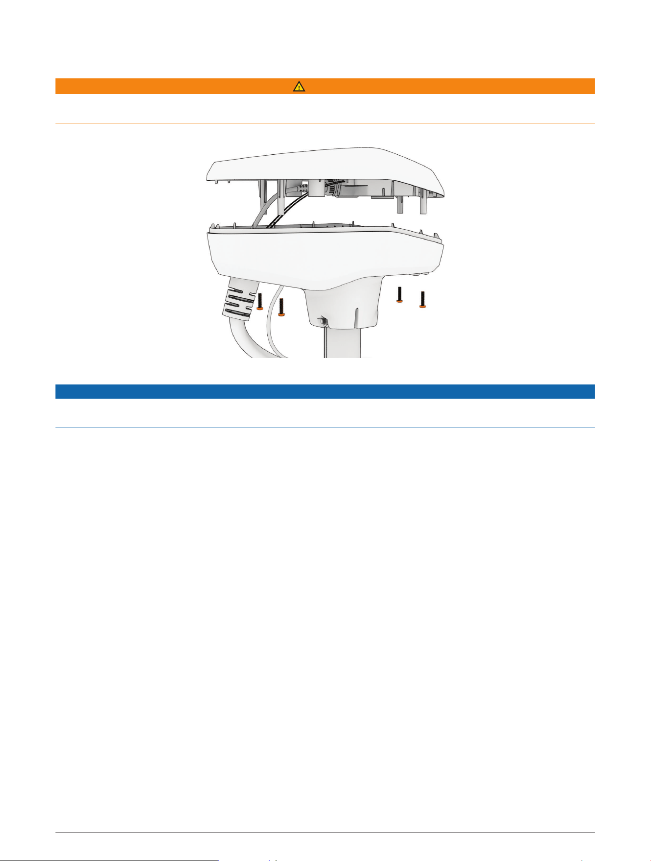
1 Using a #2 Phillips screwdriver, remove the four screws that secure the lid of the shaft cap.
2 Carefully lift up the lid of the shaft cap to access the cable connectors inside.
NOTICE
There are two cables connected to the top of the shaft cap. Take care when opening the shaft cap to avoid
damaging the cables or connectors.
Service Procedures 19
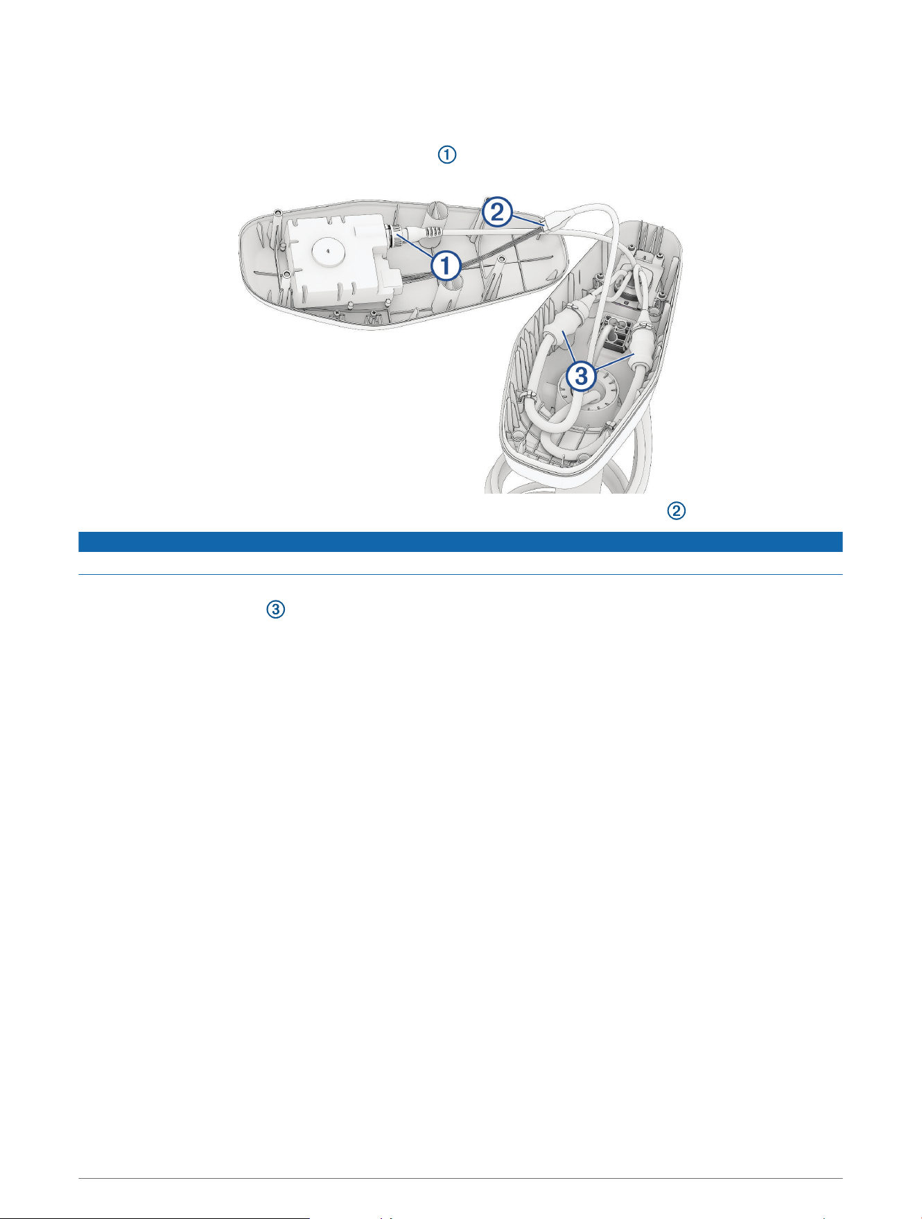
Disconnecting the Cables
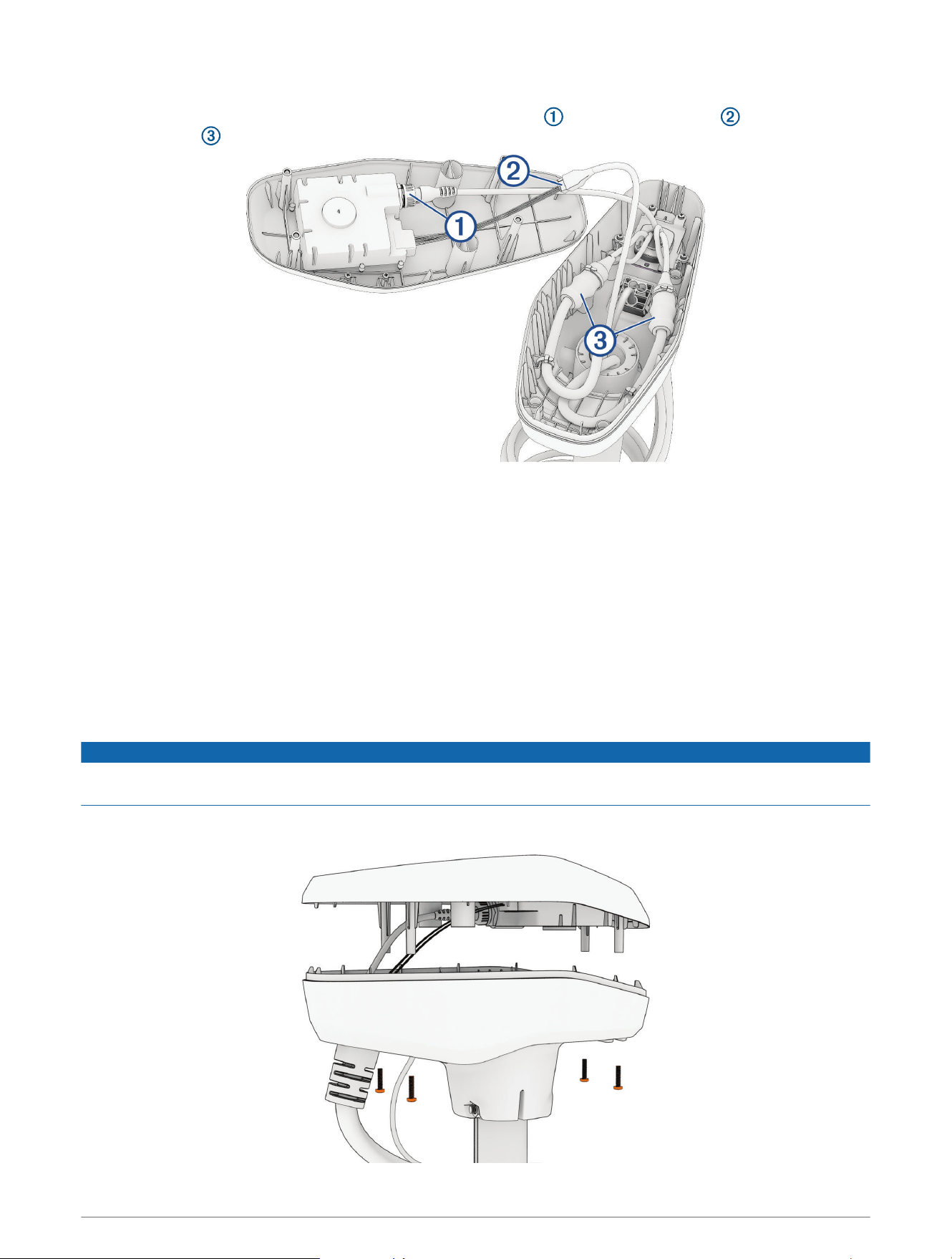
1 Take a picture or note the arrangement of the cables in the shaft cap, so you can reproduce it correctly when
you reconnect the cables and close the shaft cap.
2 Unscrew and disconnect the GPS data connector .
Ensure the o-ring remains in place inside the connector.
3 Release the latch and pull the connectors apart to disconnect the motor data cable .
NOTICE
To avoid damaging the cable, pull only on the connector body. Do not pull on the wire itself.
4 Carefully cut off the zip ties that secure the cables to the sides of the shaft cap.
5 Slide the rubber sleeves away from the connection points on the power cables.
6 Using a 2.5 mm hex bit or wrench, loosen the set screws that secure each power cable connection.
7 Disconnect the power cables.
8 Remove the rubber sleeves from the power cables and set them aside.
20 Service Procedures
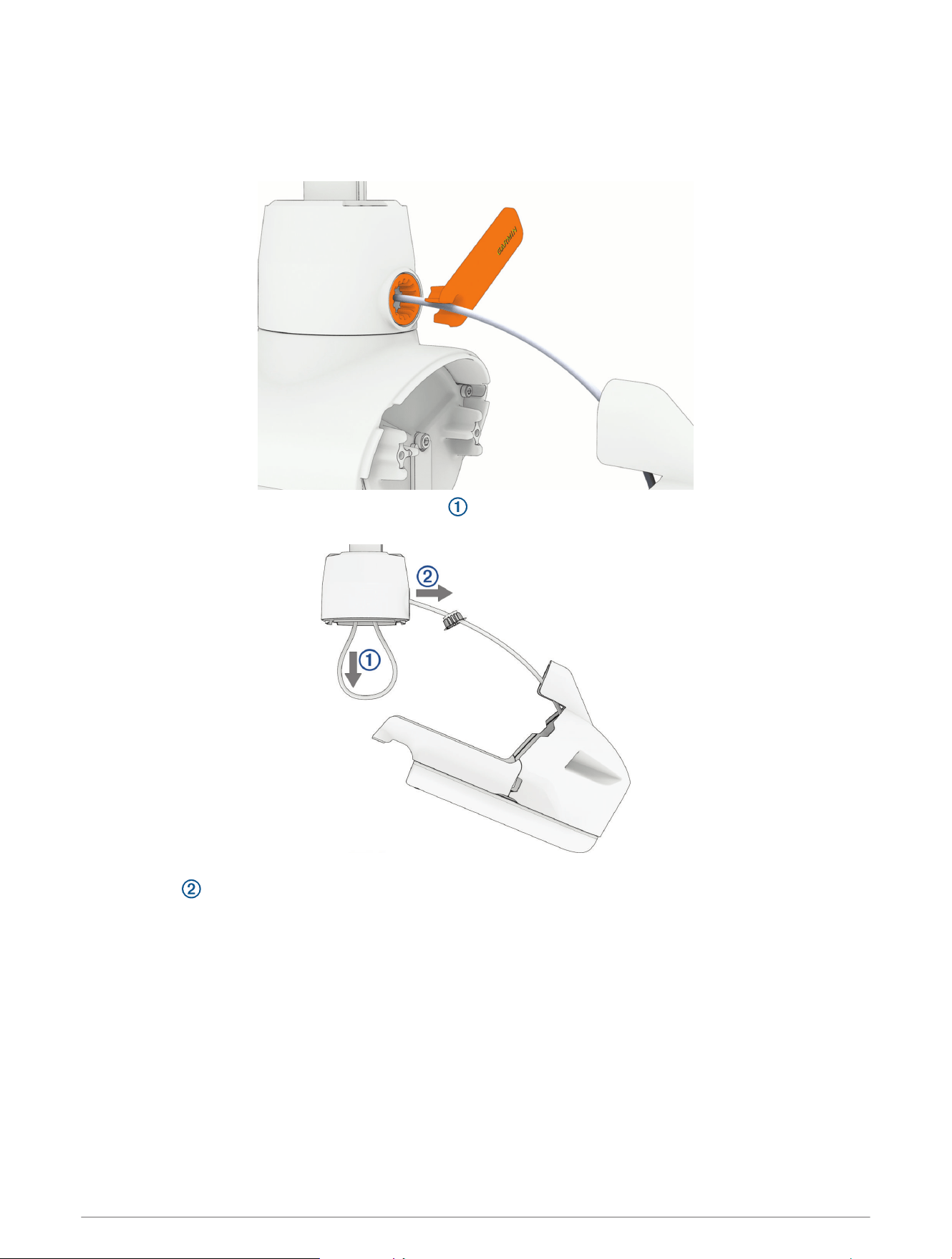
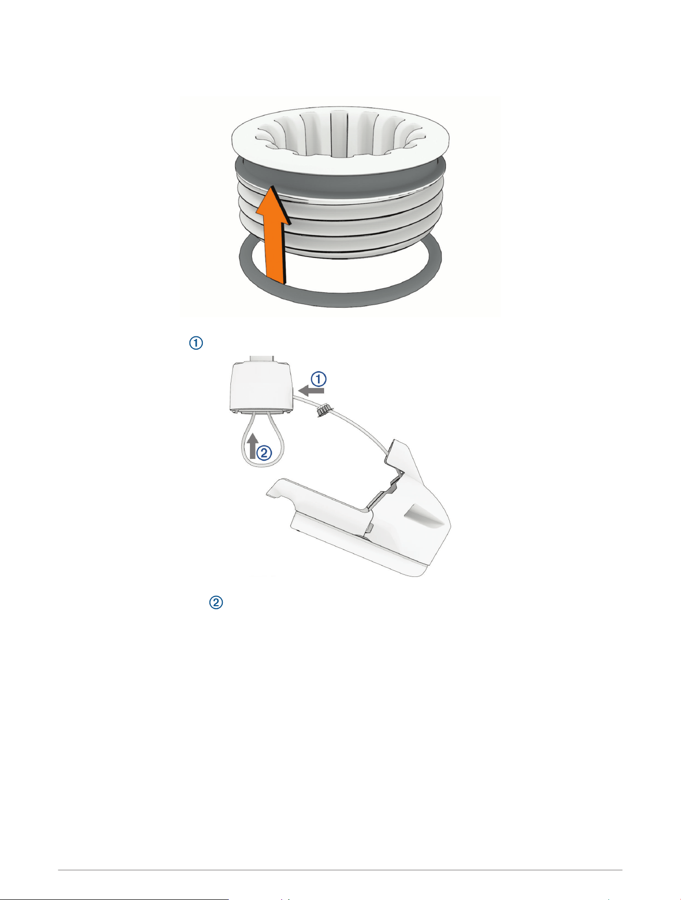
Removing the Transducer Cable
1 Remove the power and transducer cables from the mount (Removing the Power and Transducer Cables From
the Mount, page12).
2 Remove the plastic cable clamps that secure the transducer cable to the coiled power cable.
You should keep these cable clamps in a safe place, because you must reinstall them later.
3 Push from the inside out to remove the square grommet that holds the transducer cable in the shaft
cap.
4 Remove the grommet from the transducer cable.
The grommet is split on one side to make it easy to remove from the cable.
You should keep the grommet in a safe place, because you must reinstall it later.
5 Feed the transducer cable through the shaft cap from the outside in until it is no longer routed through the
square hole.
Service Procedures 21
Removing the Shaft Cap
1 Take a picture or write down the number of times the coil cable wraps around the shaft.
When reinstalling the shaft cap, you will need to make sure the cable wraps around the shaft the same
number of times.
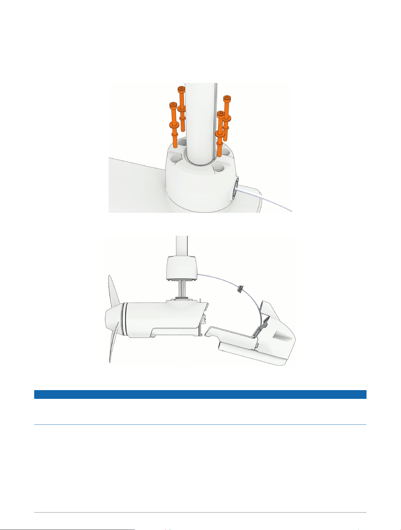
2 Using a #3 Phillips screwdriver, remove the
1
/
4
–20 bolts , lock washers, and nuts that secure the shaft
cap to the shaft.
You should keep these bolts and nuts in a safe place, because you must use them when reinstalling the shaft
cap.
3 Lift up the shaft cap to disconnect it from the shaft.
4 Pull the cables completely through the shaft cap, taking care to avoid damaging the cable connectors when
you pull them through.
Removing the Depth Limiter
1 Remove the screws from each half of the depth limiter, and pull the pieces away from the shaft.
2 Lift up to remove the bushings from inside the steering system housing.
22 Service Procedures
Removing the Shaft
CAUTION
You must make sure the motor is securely latched in the deployed position before you proceed with this service.
Working on the motor while the latch is not securely engaged may cause the motor to shift, potentially leading
to entrapment or pinching, which can result in personal injury.
We recommend having a second installer support the propeller drive motor while you loosen the depth
adjustment collar. The shaft may suddenly slide down and out of the steering system, potentially causing
personal injury or property damage.
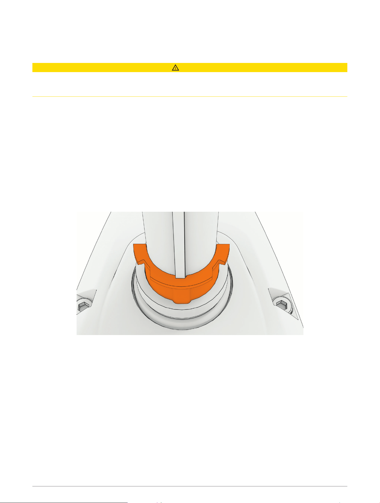
1 While making sure the weight of the propeller drive motor is supported, loosen the depth adjustment collar
on the base of the steering system.
2 Slide the shaft down and out of the steering system, taking care not to damage the skeg and transducer or
snag the cables or connectors as you pull it through.
Removing the Depth-Adjustment Collar
Before you can remove the depth-adjustment collar, you must remove the shaft from the steering system
(Removing the Shaft, page23).
Turn the depth-adjustment collar counter-clockwise until it comes off the steering system.
Removing the Propeller Drive Motor from the Shaft
Before you can remove the propeller drive motor and transducer from the shaft, you must remove the shaft from
the steering system (Removing the Shaft from the Steering System, page18).
1 Remove the skeg and nose cone from the propeller drive motor (Removing the Skeg and Nose Cone,
page24).
2 Remove the propeller drive motor from the shaft (Removing the Propeller Drive Motor, page25).
Service Procedures 23
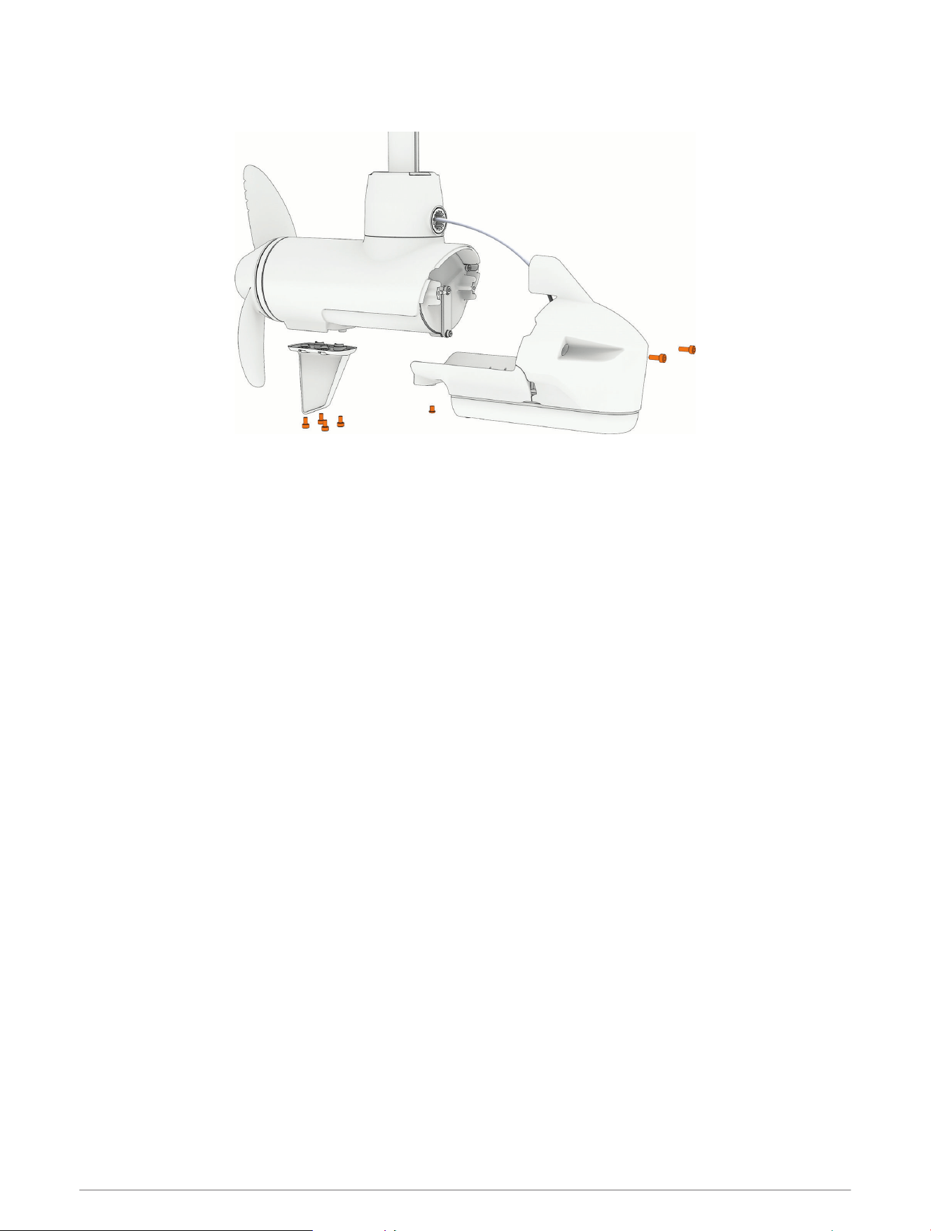
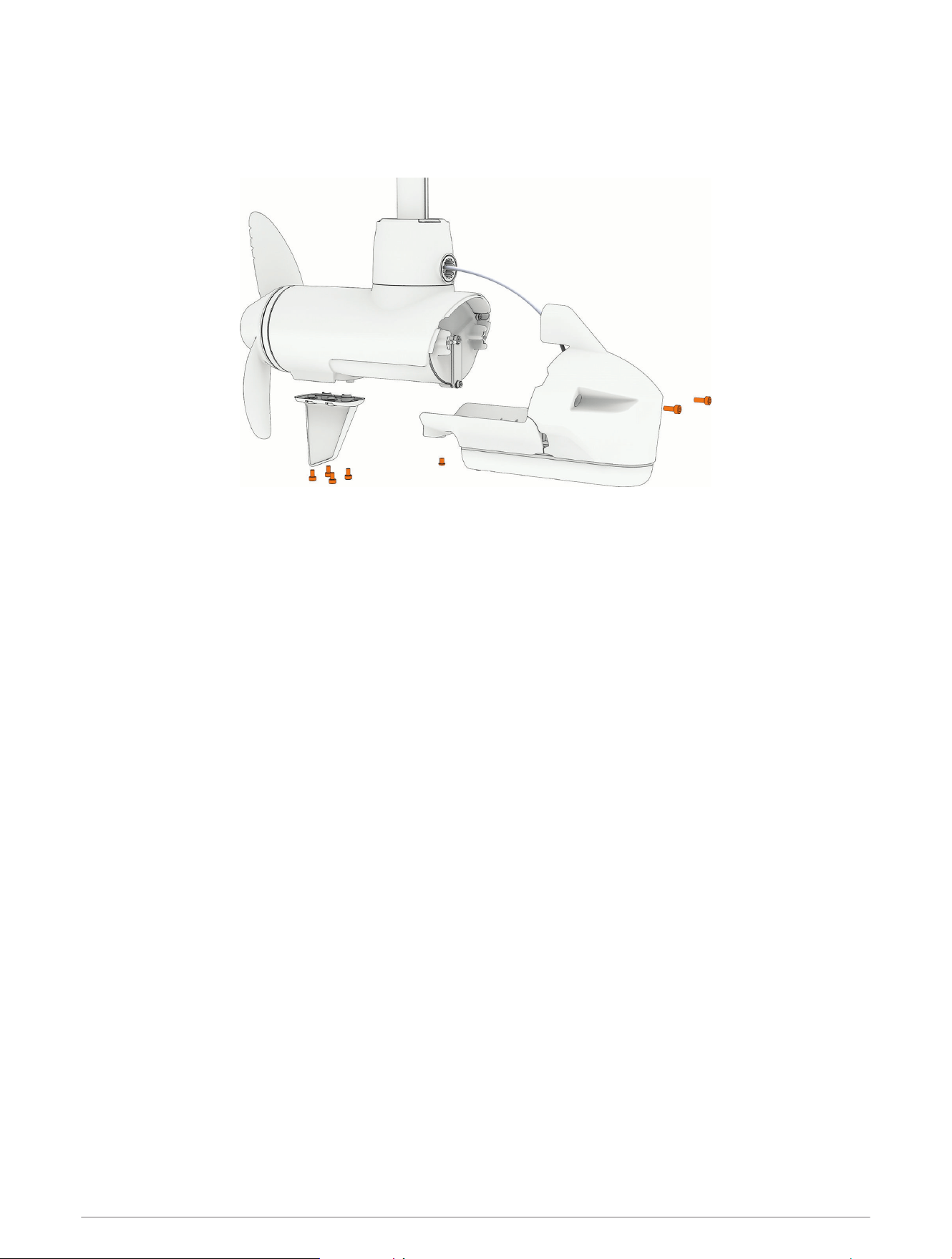
Removing the Skeg and Nose Cone
1 Using a 4mm hex bit or wrench, remove the four screws that secure the skeg to the propeller drive motor.
2 Remove the skeg.
3 Using a 4mm hex bit or wrench, remove the two screws that secure the front of the nose cone to the
propeller drive motor.
4 Using a 3mm hex bit or wrench, remove the single screw that secures the bottom of the nose cone to the
propeller drive motor.
NOTE: You should keep all of these screws and parts in a safe place, because you will reuse them when
reassembling the skeg and nose cone.
24 Service Procedures
Removing the Propeller Drive Motor
NOTE: When removing the propeller drive motor, we recommend using a ball-head hex bit or wrench because of
the angle needed to reach the head of the screws.
1 Using a ball-head 4mm hex bit or wrench, remove the screws that secure the shaft base to the propeller
drive motor.
2 Straighten the cables at the top of the shaft, and slowly pull the propeller drive motor away from the shaft
base until you can see the power and data cables connected to the propeller drive motor.
3 Holding the cables only, slowly pull them out of the shaft, taking care that the cable connectors do not get
caught on the top of the shaft.
NOTICE
When removing the propeller drive motor and pulling its cables out of the shaft, pull only on the cables
themselves and do not let the cables to support the weight of the motor. Pulling on the propeller drive motor or
letting the cables support the weight of the motor may damage the cable connections inside the motor.
4 Pull the propeller drive motor cables completely out of the shaft and set the propeller drive motor aside.
Service Procedures 25
Removing the Transducer Cable from the Shaft
Removing the recessed nut to release the transducer cable requires a custom spanner wrench. The spanner
wrench is included in the transducer replacement kit and in the shaft hardware service kit.
1 Using the custom spanner wrench, remove the recessed nut that secures the transducer cable to the shaft.
2 Carefully pull the transducer cable straight down through the bottom of the shaft until it is completely
removed from the shaft.
3 After you pull the transducer cable through the shaft completely, pull it through the hole in the front of the
shaft base , along with the cable gland.
26 Service Procedures
Installing the Transducer Cable in the Shaft
1 If necessary, place the 25mm (1in.) O-ring on the recessed nut.
2 With the O-ring facing the transducer, feed the transducer cable through the recessed nut and the hole in the
front of the shaft base , but do not feed the cable up through the shaft.
3 Leaving about 60cm (2ft.) of the transducer cable out of the front of the shaft base, feed the transducer
cable up through the shaft .
Service Procedures 27
Removing the Transducer from the Nose Cone
Before you can remove the transducer from the nose cone, you must remove the skeg and nose cone from the
propeller drive motor (Removing the Skeg and Nose Cone, page24).
Using a 3mm hex bit or driver, remove the screws that secure the transducer to the nose cone parts.
Installing the Transducer on the Nose Cone
Align the two pieces of the nose cone with the transducer and, using a 3mm hex bit or wrench, secure them
to the transducer using the screws and bushings.
Replacing the Nose Cone
1 Remove the skeg and nose cone from the propeller drive motor (Removing the Skeg and Nose Cone,
page24).
2 Remove the transducer from the existing nose cone (Removing the Transducer from the Nose Cone,
page28).
3 Install the transducer on the new nose cone (Installing the Transducer on the Nose Cone, page28).
4 Install the nose cone and skeg on the propeller drive motor (Installing the Nose Cone and Skeg, page32).
28 Service Procedures
Installing the Propeller Drive Motor on the Shaft
NOTICE
You must use new hardware and seals when reinstalling the propeller drive motor. Reusing old hardware and
seals can lead to water ingress and damage to the motor. Replacement screws, seals, and a grease packet are
included in the propeller drive motor hardware service kit (S00-01000-35).
1 Install the propeller drive motor on the shaft (Installing the Propeller Drive Motor, page29).
2 If necessary, install the cable gland and recessed nut (Installing the Cable Gland and Recessed Nut,
page31).
3 Install the nose cone and skeg on the propeller drive motor (Installing the Nose Cone and Skeg, page32).
Installing the Propeller Drive Motor
Before you can install the propeller drive motor in the shaft, you must route the transducer cable through the
shaft (if applicable) (Installing the Transducer Cable in the Shaft, page27).
1 Remove the large 78mm (3in.) O-ring on the shaft base, and discard it.
2 Using the packet included in the shaft and motor hardware service kit, apply grease to the new 78mm (3in.)
O-ring in the shaft and motor hardware service kit.
3 Place the new 78mm (3in.) O-ring in the groove on the shaft base.
4 Using canned compressed air or an air compressor, blow out any dirt or debris in the four threaded holes on
the top of the propeller drive motor.
5 Apply a medium-strength thread-locking compound such as LOCTITE
®
243
™
to the threads in the four
threaded holes on the top of the propeller drive motor.
NOTICE
Thread-locking compound is required in these holes to maintain a tight connection between the shaft base and
the propeller drive motor. Failure to use thread-locking compound can lead to water ingress and damage to the
motor.
6 Remove the 36mm (1
7
/
16
in.) O-ring from the top of the propeller drive motor, and discard it.
7 Thread the cables from the propeller drive motor through the new 36mm (1
7
/
16
in.) O-ring in the shaft and
motor hardware service kit.
Service Procedures 29
8 Using the packet included in the shaft and motor hardware service kit, apply grease to the new 36mm
(1
7
/
16
in.) O-ring.
9 Place the new 36mm (1
7
/
16
in.) O-ring in the groove on the top of the propeller drive motor.
10 If the power and data cables from the propeller drive motor are not already aligned and bundled, straighten,
align, and bundle them with tape.
If the power and data cables are not straight and aligned, they may not feed through the shaft smoothly.
11 Feed the power and data cables from the propeller drive motor up through the shaft until they emerge from
the top.
NOTICE
When the cables emerge into the shaft cap, you must avoid pulling on connectors. The connectors on the
propeller drive motor cables are fragile and may be damaged by pulling. If necessary, pull only on the cables
themselves and avoid putting any strain on the connectors.
12 Prepare the four bolts in the shaft and motor hardware service kit by placing a washer and a 4.75mm
(
3
/
16
in.) O-ring on each one.
13 Using the grease packet included in the shaft and motor hardware service kit, apply grease to the 4.75mm
(
3
/
16
in.) O-ring on each bolt.
Avoid getting grease on the bolt threads.
REMEMBER: If you did not previously apply thread-locking compound in the four mounting holes for these
bolts, you must apply it before installing these bolts.
30 Service Procedures
14 Using a ball-head 4mm hex bit or wrench, thread all four of the prepared bolts approximately halfway to
make sure that the shaft base and the propeller drive motor are properly aligned.
15 With the shaft base and the propeller drive motor properly aligned, lightly tighten all four bolts by hand.
16 Using a torque wrench, tighten all four bolts to 4N-m (35lbf-in).
Installing the Cable Gland and Recessed Nut
Before you can install the cable gland and recessed nut, you must install the propeller drive motor on the shaft
base (Installing the Propeller Drive Motor, page29).
1 From the shaft and motor hardware service kit, select a new cable gland that fits your transducer cable:
• For a 4-pin transducer, select the cable gland with the smaller hole.
• For an 8- or 12-pin transducer, select the cable gland with the larger hole.
NOTE: A cable gland without a hole is provided if you are not installing a transducer or not routing the
transducer cable through the shaft.
2 Measure 20cm (8in.) from the point the transducer cable enters the transducer, and mark the transducer
cable using a permanent marker.
3 Using the packet included in the shaft and motor hardware service kit, apply grease completely to all
surfaces of the cable gland you selected to fit your transducer cable.
4 Place the cable gland at the marked location on the transducer cable.
5 While keeping the cable gland aligned with the mark on the transducer cable, gently pull the excess cable
through the top of the shaft until the cable gland fits into the hole on the shaft base.
6 Using the packet included in the shaft and motor hardware service kit, apply grease to the 25mm (1in.)
O-ring on the recessed nut on the transducer cable.
7 Place the recessed nut into the hole on the shaft base.
8 Using the spanner wrench, tighten the recessed nut until it stops.
Service Procedures 31
Installing the Nose Cone and Skeg
1 Place the nose cone onto the propeller drive motor.
2 Using a 4mm hex bit or wrench, secure the front of the nose cone to the propeller drive motor using the two
existing screws.
3 Using a 3mm hex bit or wrench, secure the bottom of the nose cone to the propeller drive motor using the
existing screw.
4 Using a 4mm hex bit or wrench, secure the skeg to the bottom of the propeller drive motor using the four
existing screws.
Installing the Shaft in the Steering System
1 Install the shaft in the steering system (Reinstalling the Shaft, page33).
2 Install the shaft cap on the shaft (Installing the Shaft Cap, page34).
3 Install the transducer cable in the shaft cap (Reinstalling the Transducer Cable, page35).
4 Connect the cables in the shaft cap (Reconnecting the Cables, page36).
5 Close the shaft cap (Closing the Shaft Cap, page36).
6 Route the power and transducer cables through the mount (Routing the Power and Transducer Cables
Through the Mount, page13).
32 Service Procedures
Reinstalling the Shaft
If you removed the depth-adjustment collar (Removing the Depth-Adjustment Collar, page23), you must reinstall
it before you install the shaft in the steering system.
CAUTION
We recommend having a second installer support the propeller drive motor while you feed the shaft through the
steering system and tighten the depth adjustment collar. If the shaft slides down and out of the steering system,
it may cause personal injury or property damage.
1 Feed the transducer cable up through the steering system.
2 Insert the shaft into the bottom of the steering system, guiding the power and data connectors into the
steering system to prevent snagging the cables or connectors.
NOTE: The shaft fits in the steering system only in a certain orientation. If you encounter any resistance,
remove the shaft, rotate it a few degrees, and try again. When it is in the correct orientation, the shaft will
slide into the steering system easily.
3 Push the shaft up the steering system to a comfortable height for you to access the top of the shaft, and
tighten the depth adjustment collar on the base of the steering system.
4 Place the keyed bushing over the keyed side of the shaft, and slide it down until its lip rests on the steering
system housing.
NOTE: The keyed bushing fits in the steering system only in a certain orientation. While someone supports
the weight of the propeller drive motor on the bottom of the shaft, you can loosen the depth adjustment
collar and rotate the shaft and bushing to match the position of the notch in the steering system.
5 Install the smooth bushing over the other side of the shaft and slide it down until its lip rests on the steering
system housing.
Service Procedures 33
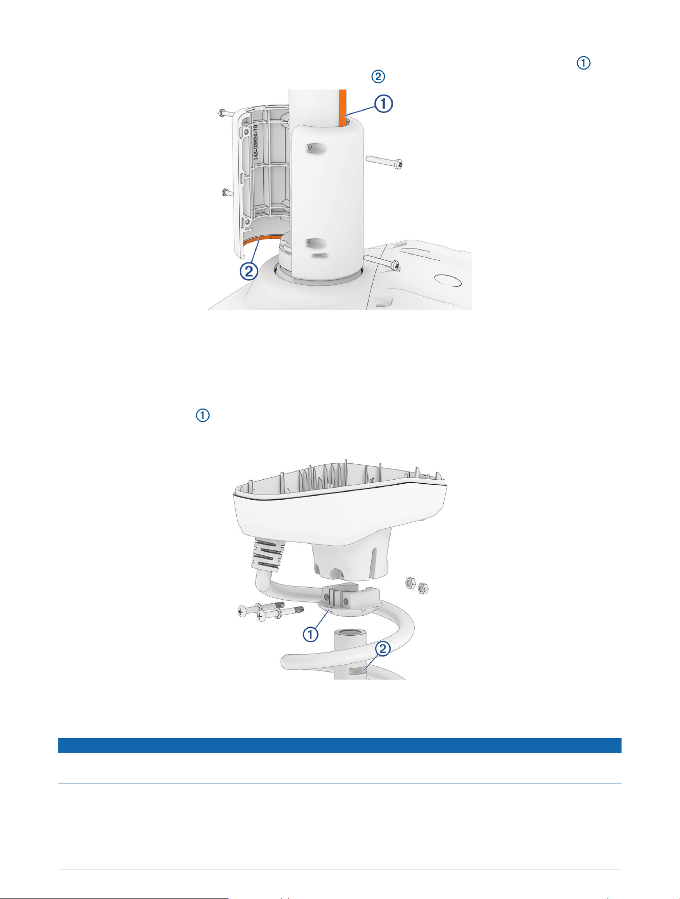
6 Place both halves of the depth limiter around the shaft so that one half fits over the key on the shaft , and
both halves overlap the top of the steering system housing .
7 Using a #2 Phillips screwdriver, install the 3mm pan head screws to secure both halves of depth limiter
together.
When the depth limiter is installed properly, it rotates with the shaft and cannot slide up the shaft.
8 Reinstall the shaft cap (Installing the Shaft Cap, page34).
Installing the Shaft Cap
1 Insert the rubber wedge into the bottom of the shaft cap.
NOTE: The rubber wedge fits in the shaft cap in one orientation only. You should examine the shape of the
inside of the shaft cap and the shape of the rubber wedge to determine the correct fit.
2 Pull the cables from the shaft completely through the shaft cap.
3 Place the shaft cap on the shaft, making sure the coil cable wraps around the shaft the same number of
times it did before you removed the shaft cap.
NOTICE
You must make sure the coil cable wraps around the shaft the same number of times it did before you removed
the shaft cap, to prevent unnecessary wear that may lead to a premature failure of the coil cable.
NOTE: Check the orientation of the shaft cap relative to the orientation of the propeller drive motor. The
cables exiting the shaft cap must be on the same side as the propeller, so that the arrow on the shaft cap
cover will point forward, relative to the propeller thrust.
34 Service Procedures
4 Push the shaft cap down until the bolt holes on the shaft cap align with the grooves on the shaft.
5 Apply a medium-strength thread-locking compound such as LOCTITE 243 to the ends of the
1
/
4
–20 bolts.
6 Install the
1
/
4
–20 bolts and split washers into the bottom of the shaft cap.
NOTE: The bolts should slide all the way through the bottom of the shaft cap easily. If you encounter any
resistance, you should rotate the shaft cap from side to side while pushing down on it until it is seated
correctly and you can easily insert the bolts all the way through.
7 Using a #3 Phillips bit or screwdriver, secure the bolts to the nuts and lock the shaft cap in place.
NOTE: The holes on one side of the shaft cap are shaped to hold the nut in place while you drive the screws
from the other side.
Reinstalling the Transducer Cable
1 Feed the transducer cable completely through the square hole in the shaft cap.
2 Install the grommet on the transducer cable.
The grommet is split on one side to make it easy to install on the cable.
3 Push from the outside to secure the square grommet in the shaft cap.
4 Route the transducer cable alongside the coil cable, using the cable clamps to hold the cables together.
5 Route the transducer cable through the mount base alongside the coil cable, using the cable clamps to
secure the cables to the base.
6 Route the transducer cable to the chartplotter and connect it.
Service Procedures 35
Reconnecting the Cables
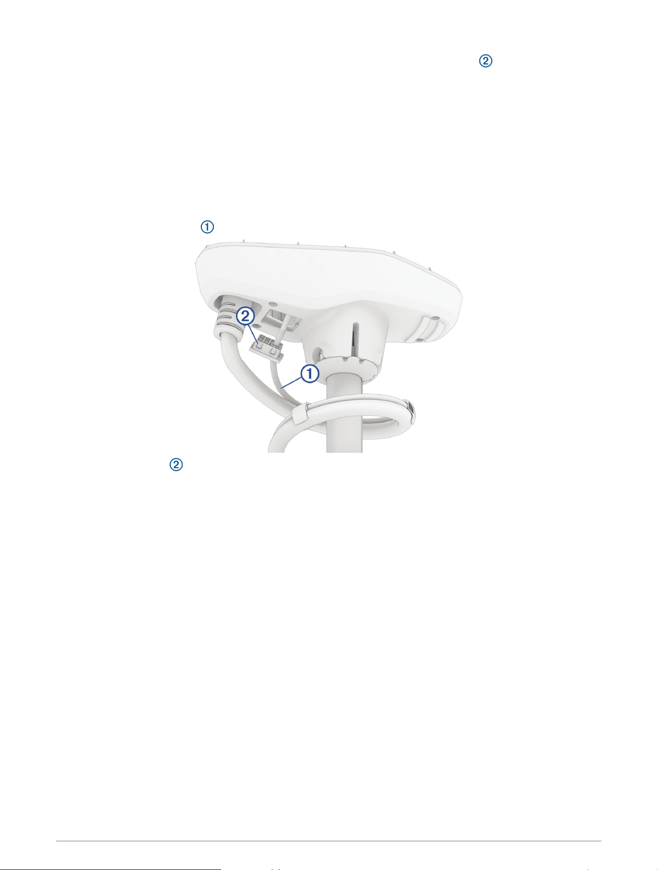
1 Add dielectric grease to the connectors on the GPS data cable , the motor data cable , and the motor
power cables .
2 Place the rubber sleeves on the power cables from the shaft, so that you can later slip them over the power
cable connections.
3 Reconnect the power cables and, using a 2.5 mm hex bit or wrench, tighten the set screws.
4 Slip the rubber sleeves over the power cable connections.
5 Secure the power cables to the sides of the shaft cap using cable ties, following the arrangement you noted
before cutting the original cable ties.
6 Reconnect the GPS data cable to the connector on the shaft cap cover, and tighten the collar.
7 Reconnect the motor data cable, aligning the connectors so that the latch is engaged and the connection is
secure.
Closing the Shaft Cap
1 Place the lid on the shaft cap.
NOTICE
Ensure the cables are routed away from pinch points before securing the shaft cap lid to avoid damaging the
cables.
2 Using a #2 Phillips bit or screwdriver, install the four screws you removed previously to secure the lid of the
shaft cap.
36 Service Procedures
Connecting the Steering System to the Mount
1 Connect the steering system to the lower link of the mount (Installing the Steering System on the Lower Link
of the Mount, page37).
2 Secure the upper gas spring (Securing the Upper Gas Spring, page40).
3 Connect the upper link of the mount to the steering system (Connecting the Upper Link of the Mount to the
Steering System, page40).
4 Connect the motor to the display panel (Connecting the Motor to the Display Panel, page42).
5 Secure the lower gas spring (Securing the Lower Gas Spring, page43).
6 Route the power and transducer cables through the mount (Routing the Power and Transducer Cables
Through the Mount, page13).
Installing the Steering System on the Lower Link of the Mount
1 Pivot the lower link of the mount forward until it locks into the base.
2 Push the two safety rods into the lower link as far as possible.
Service Procedures 37
3 Make sure that the bushings are installed in the lower holes on the steering system housing.
If the bushings were removed, you can re-insert them from the inside out.
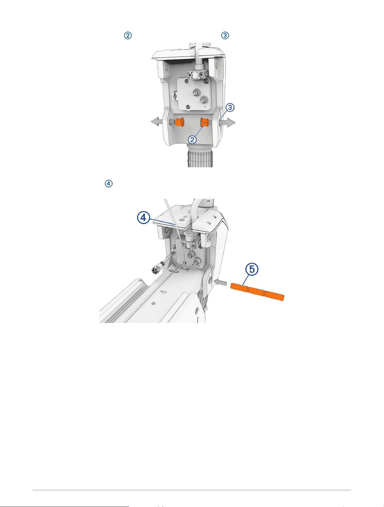
4 Holding the pull cable up, place the steering system onto the lower link of the mount, aligning the lower
holes on the housing with the holes on the link.
38 Service Procedures
5 While lifting up on the steering system, push the pivot pin through the housing and the link to hold it in
place.
NOTICE
Do not hit the pin with a hammer or other object. Do not drill or modify the holes. Although it is a snug fit, the pin
slides in completely when pushed by hand. Damage caused by hammering the pin or modifying the holes is not
covered under warranty.
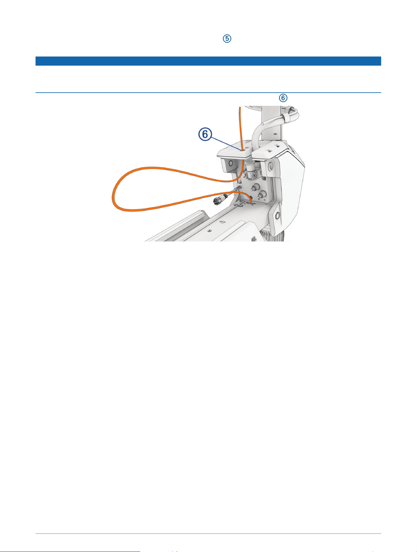
6 Route the pull cable upward through the top of the steering system housing .
Service Procedures 39
Securing the Upper Gas Spring
1 Push the safety rod toward the steering system as far as possible to lock the lower pivot pin in place.
2 If necessary, pivot the upper gas spring toward the lower link of the mount so the base of the gas spring
aligns with the safety rod and mounting holes.
CAUTION
If you must rotate the gas spring so the base aligns with the mount, rotate the spring in a clockwise direction
only. Rotating the gas spring in a counter-clockwise direction may loosen the fittings, potentially leading to a
premature failure of the gas spring, which could lead to personal injury or property damage while stowing or
deploying the motor.
3 Align the single hole on the base of the gas spring with the safety rod, and press down.
The screw holes on the base should align with the holes on the bottom of the mount.
4 Using a #2 Phillips screwdriver, secure the base of the gas spring to the lower link of the mount using the
included screws .
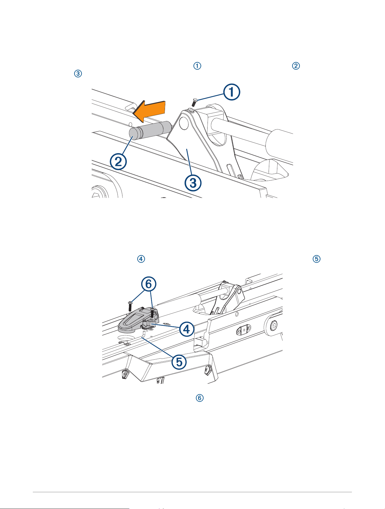
Connecting the Upper Link of the Mount to the Steering System
1 Make sure that the data cable is accessible, and not trapped by any part of the mount.
2 Make sure that the bushings are installed in the upper holes on the steering system housing.
If the bushings were removed, you can re-insert them from the outside in.
40 Service Procedures
3 Pivot the upper link of the mount forward.
4 Tip the top of the steering system inward so the holes on the upper link and the housing align.
5 Push the pin through the holes on the upper link of the mount and the steering system housing.
6 Using a 4mm hex bit or hex wrench, secure the pin using the screws and washers on both sides.
NOTE: To properly secure the pin, you should use two hex bits or wrenches so the pin does not rotate as you
tighten the screws.
Service Procedures 41
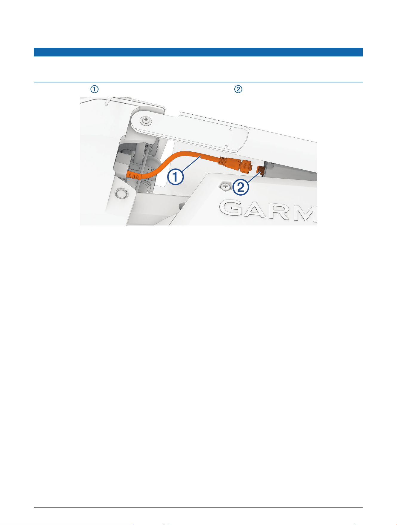
Connecting the Motor to the Display Panel
NOTICE
You must connect the cable from the steering system to the display panel before proceeding further with
assembly. If you do not make this connection now, the unsecured cable may damage the display panel when
moving the mount.
1 Route the cable from the steering system to the display panel on the upper link of the mount.
2 Push the connector onto the port on the display panel, and rotate the locking ring clockwise to secure it.
NOTE: The connector is keyed to fit into the port one way only, and will fit easily when aligned correctly. Do
not force the connector into the port.
42 Service Procedures
Securing the Lower Gas Spring
1 If necessary, transition the trolling motor from the deployed to the stowed position.
If the gas spring is positioned on the other side of the mount after you stowed the motor, you may need to lift
up the mount and flip over the gas spring so you can secure it to the mount.
2 Align the hole on the base of the lower gas spring with the safety rod , and press down.
CAUTION
If you must rotate the gas spring so the base aligns with the mount, rotate the spring in a clockwise direction
only. Rotating the gas spring in a counter-clockwise direction may loosen the fittings, potentially leading to a
premature failure of the gas spring, which could lead to personal injury or property damage while stowing or
deploying the motor.
3 Using a #2 Phillips screwdriver, secure the base of the lower gas spring to the mount using the screws you
removed when disconnecting the gas spring .
Service Procedures 43
Replacing the Lower Gas Spring
Before you can replace the lower gas spring, you must disconnect it from the mount (Disconnecting the Lower
Gas Spring, page15).
1 Using a #0 Phillips screwdriver, remove the set screw that secures the gas spring pin to the shaft
stabilizer on the mount.
2 Slide out the gas spring pin and lift up on the gas spring to remove it.
3 Place the end of the replacement gas spring into the shaft stabilizer on the mount.
4 Slide the gas spring pin into the shaft stabilizer, through the end of the gas spring, until it is flush with the
edge of the shaft stabilizer.
5 Install the set screw in the shaft stabilizer to secure the gas spring pin.
6 Place the lower gas spring clevis on the lower link of the mount, fitting it over the safety rod .
7 Using a #2 Phillips screwdriver, install the screws that secure the lower gas spring clevis to the lower link
of the mount.
44 Service Procedures
Replacing the Upper Gas Spring
Before you can replace the upper gas spring, you must disconnect it from the mount (Disconnecting the Upper
Gas Spring, page17).
1 Using a #0 Phillips screwdriver, remove the set screw that secures the gas spring pin to the upper gas
spring arm .
2 Slide out the gas spring pin and lift up on the gas spring to remove it.
3 Place the end of the replacement gas spring into the upper gas spring arm.
4 Slide the gas spring pin into the upper gas spring arm, through the end of the gas spring, until it is flush with
the edge of the upper gas spring arm.
5 Install the set screw in the upper gas spring arm to secure the gas spring pin.
6 Place the upper gas spring clevis on the lower link of the mount, fitting it over the safety rod .
7 Using a #2 Phillips screwdriver, install the two screws that secure the lower gas spring clevis to the lower
link of the mount.
Service Procedures 45
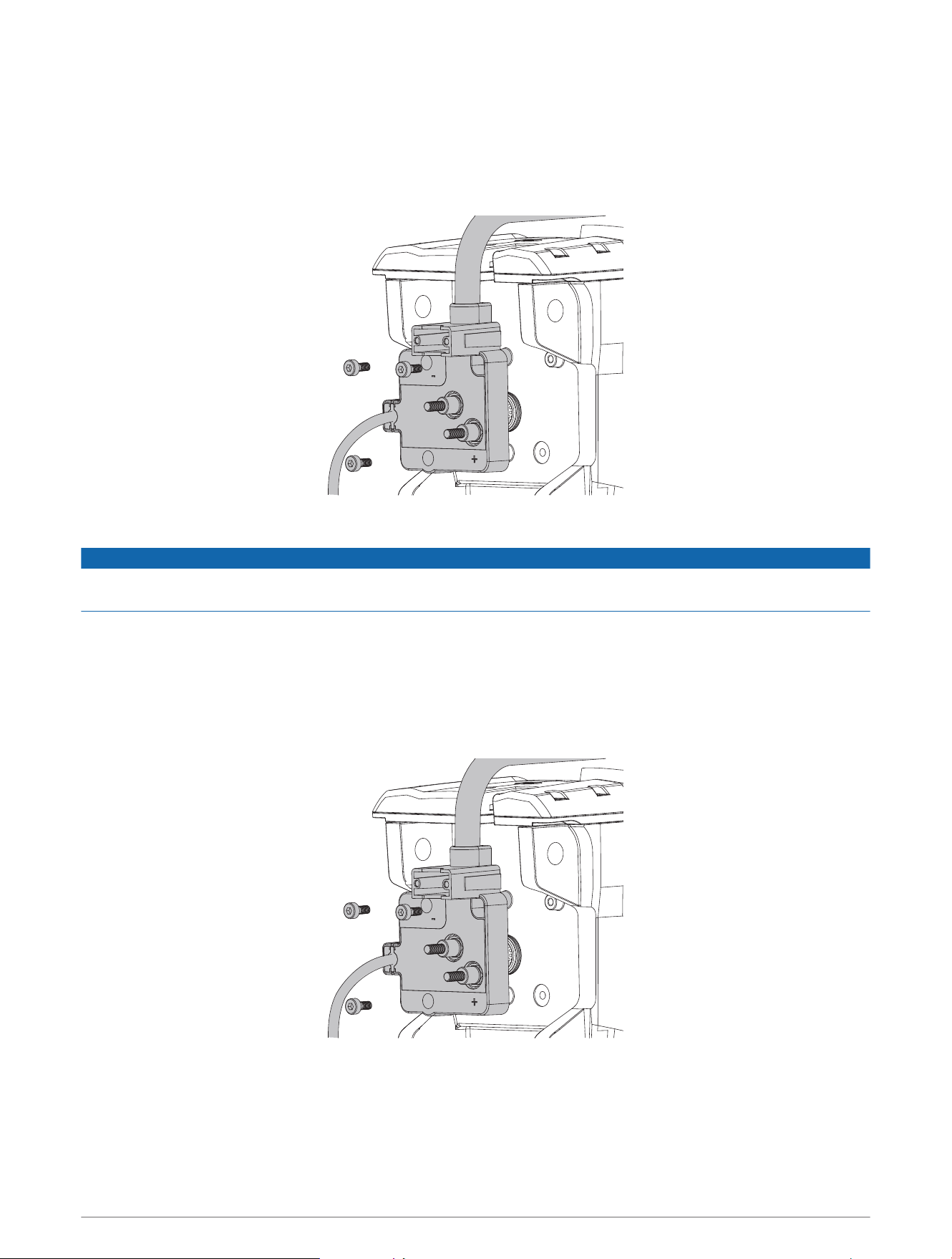
Removing the Power Cable from the Steering System
Before you can remove the power cable from the steering system, you must remove the power and transducer
cables from the mount (Removing the Power and Transducer Cables From the Mount, page12).
1 Disconnect the upper link of the mount from the steering system (Disconnecting the Upper Link from the
Steering System, page16).
2 Pivot the upper link away from the steering system.
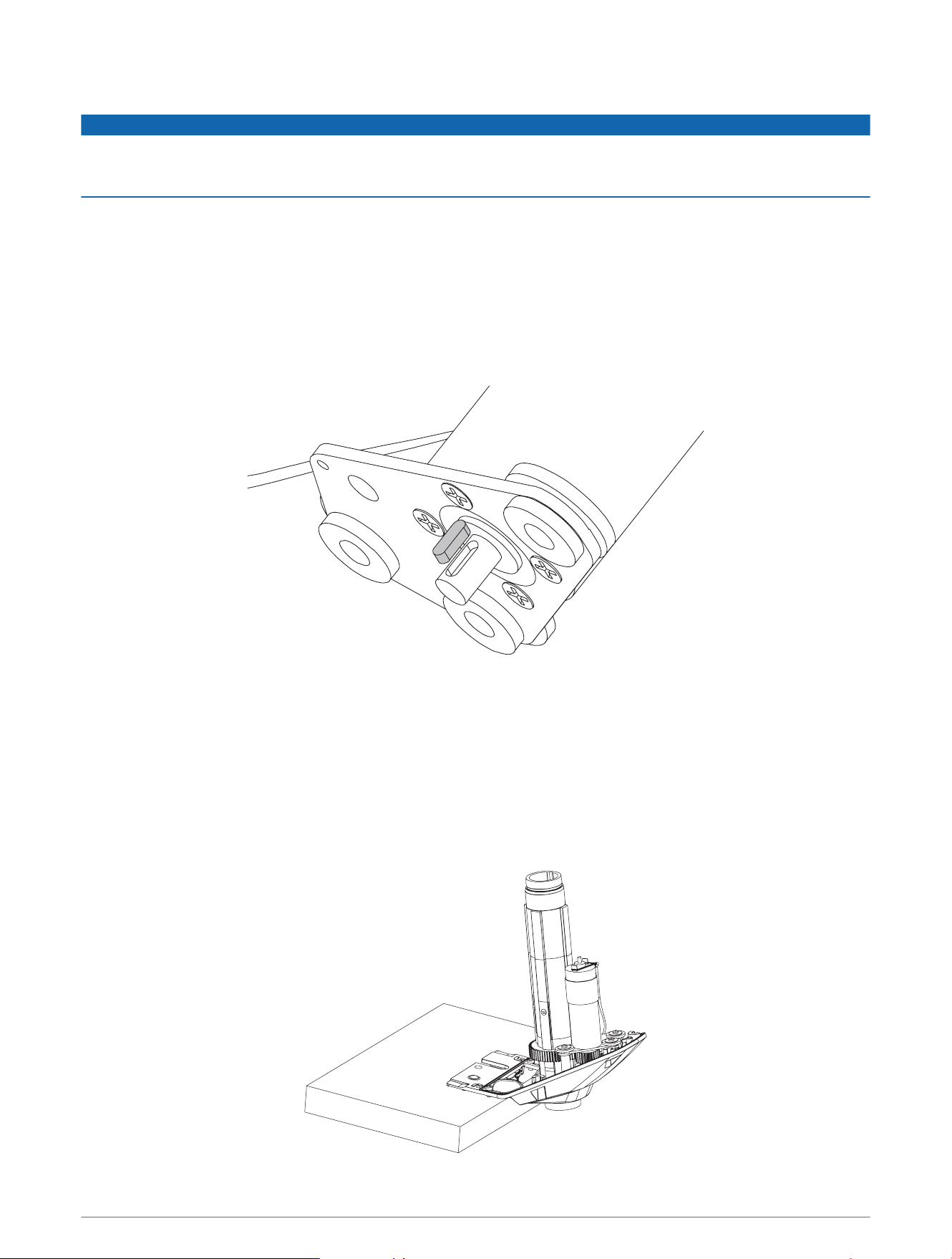
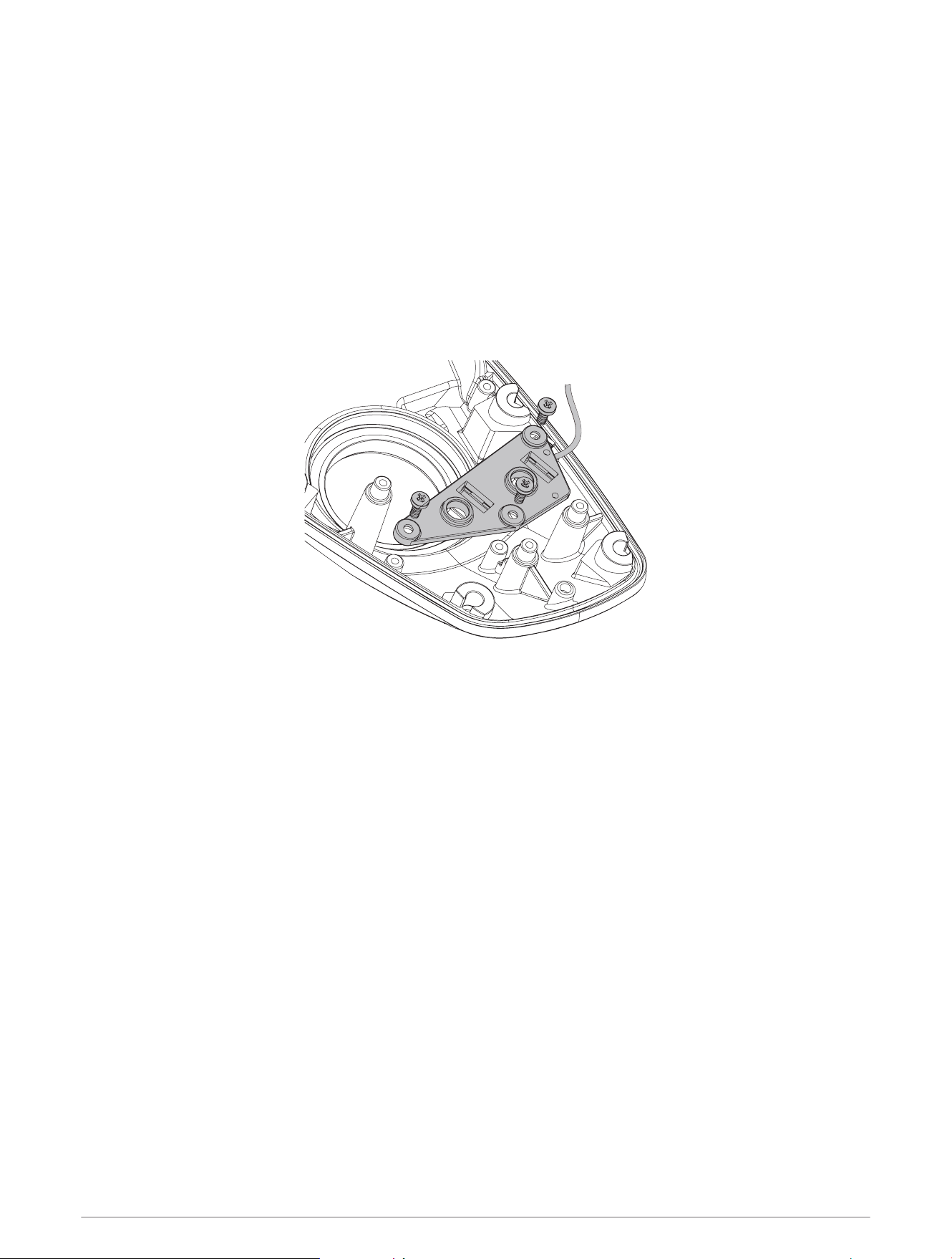
3 Using a #2 Phillips screwdriver, remove the bracket that secures the power cable to the steering system.
4 Pull the rubber shields away from the power cable terminals.
5 Using a 10mm socket, remove the nuts that secure the power cable terminals.
46 Service Procedures
Reconnecting the Power Cable
1 Pull the rubber shields away from the power cable terminals.
2 Apply dielectric grease to the ring terminals on the power cable and to the bolts on the steering system.
3 Connect the power cable terminals to the bolts on the steering system, with the red cable on the positive (+)
terminal, and the black cable on the negative (−) terminal.
4 Using a 10mm socket, install the nuts that secure the power cable connectors.
5 Tighten the nuts to at 4N-m (36lbf-in).
6 Pull the rubber shields down to cover the power cable connectors.
7 Using a #2 Phillips screwdriver, install the bracket that secures the power cable to the steering system.
8 Tighten the screws to 0.5N-m (4.3 lbf-in).
Service Procedures 47
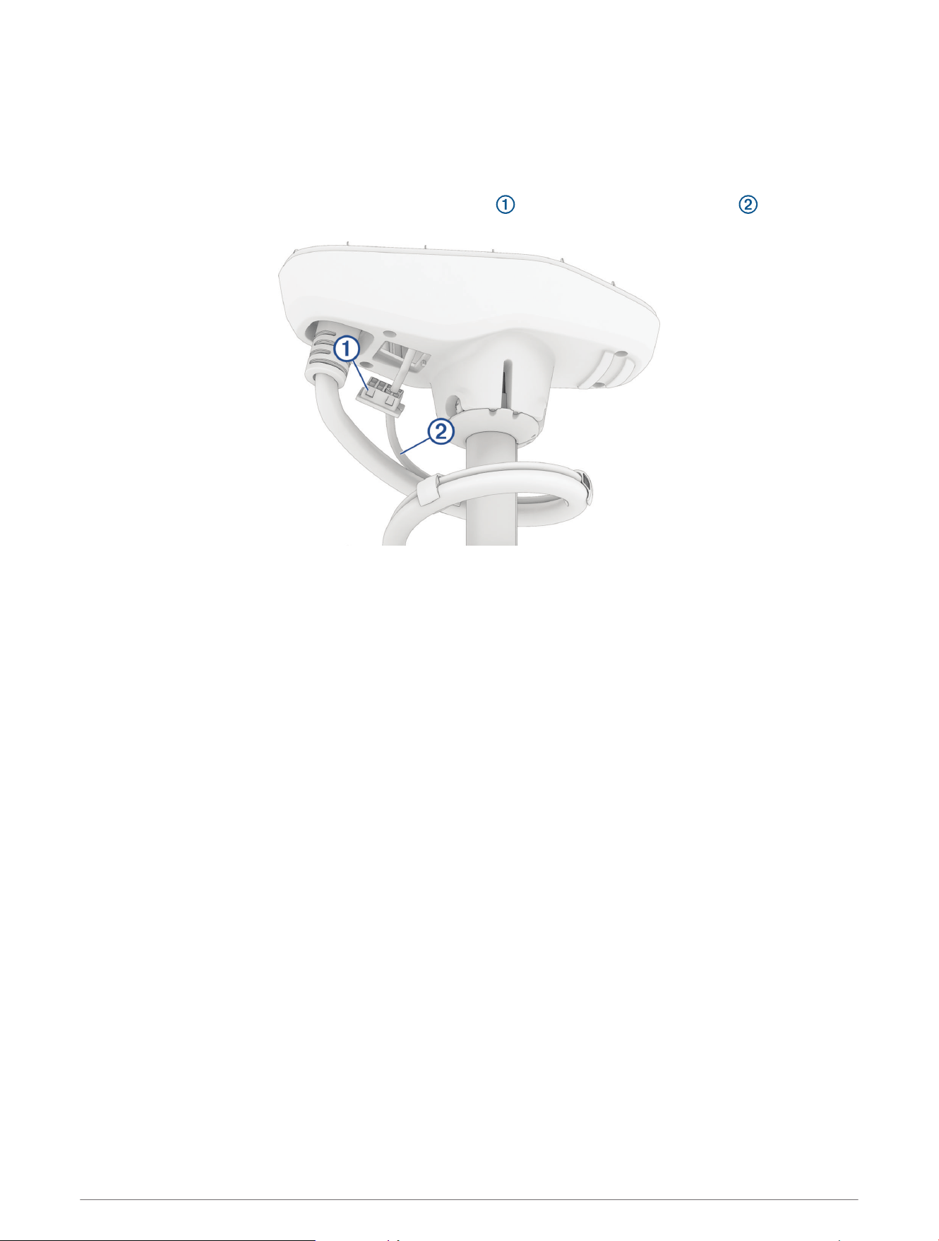
Removing the Coil Cable from the Steering System
Before you can remove the coil cable, you must disconnect the power cable from the steering system
(Removing the Power Cable from the Steering System, page46).
1 Using a 4mm hex bit or screwdriver, remove the three screws that secure the coil cable block to the steering
system.
2 Pull the coil cable block away from the steering system to remove it.
NOTICE
The coil cable block connects to the PCB in the steering system. When removing the block take care to avoid
damaging the connector on the PCB.
Installing the Coil Cable Block on the Steering System
If you are installing a replacement coil cable, we recommend installing it in the shaft first (Installing the Coil
Cable in the Shaft Cap, page49).
1 Place the coil cable block over the connector on the steering system, and push it into place, taking care to
avoid damaging the connector.
2 Using a 4 mm hex bit or screwdriver, insert and tighten the three screws to secure the coil cable block to the
steering system.
3 Tighten the three screws to 2N-m (18lbf-in)
48 Service Procedures
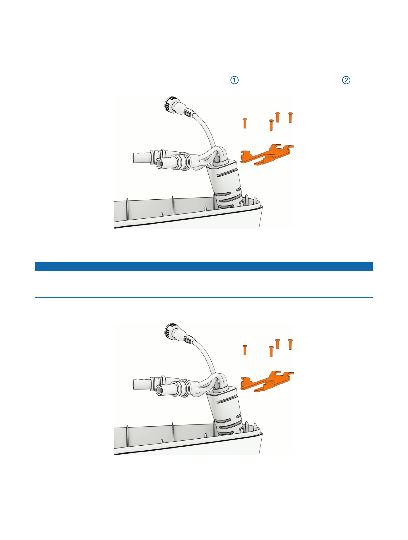
Removing the Coil Cable from the Shaft Cap
Before you can remove the coil cable from the shaft cap, you must disconnect the cables in the shaft cap
(Disconnecting the Cables, page20).
TIP: Count and record the number of coils in the coil cable before removing it to simplify reinstallation.
1 Using a #1 Phillips bit or screwdriver, remove the four screws that secure the coil cable bracket , and
slide the bracket off of the cable boot.
2 Pull the coil cable out of the shaft cap to remove it.
Installing the Coil Cable in the Shaft Cap
NOTICE
Before feeding the coil cable, ensure the coil cable has the same number of coils around the shaft as you
recorded during removal. If the cable is wound too tight or too loose, the cable may bind and restrict the motion
of the motor.
1 Feed the cables from the existing or replacement coil cable into the hole in the shaft cap.
2 Slide the coil cable bracket over the cable boot.
3 Secure the coil cable bracket to the shaft cap with the screws you removed earlier.
Service Procedures 49
Replacing the Display Panel
Before you can remove the display panel from the upper link of the mount, you must disconnect the upper link of
the mount from the steering system (Disconnecting the Upper Link from the Steering System, page16).
1 Using a #0 Phillips screwdriver, remove the position sensor from the upper link of the mount.
2 Using needle-note pliers, open the cable clips to remove the position-sensor cable.
3 Pinch the tabs on the side of the display panel, and push it out of the upper link from the back.
4 Feed the cable from the replacement display panel through the upper link, taking care to feed the cable
completely through the upper link.
NOTICE
Use caution when installing the replacement display panel to avoid pinching the cable between the display panel
and the upper link. A damaged position sensor cable may cause damage to the drive system when stowing the
motor.
5 Secure the replacement display panel by placing it in the upper link and pushing until it snaps into place.
6 Using a #0 Phillips screwdriver, secure the position sensor to the mount.
7 If necessary, install new cable clips to secure the position sensor cable along its route.
TIP: When installing new cable clips, you should avoid the areas where cable clips were affixed before, to
ensure the new cable clips will adhere well to the inside surface of the upper link.
8 Place the cable in the cable clips and close the cable clips to secure the cable.
50 Service Procedures
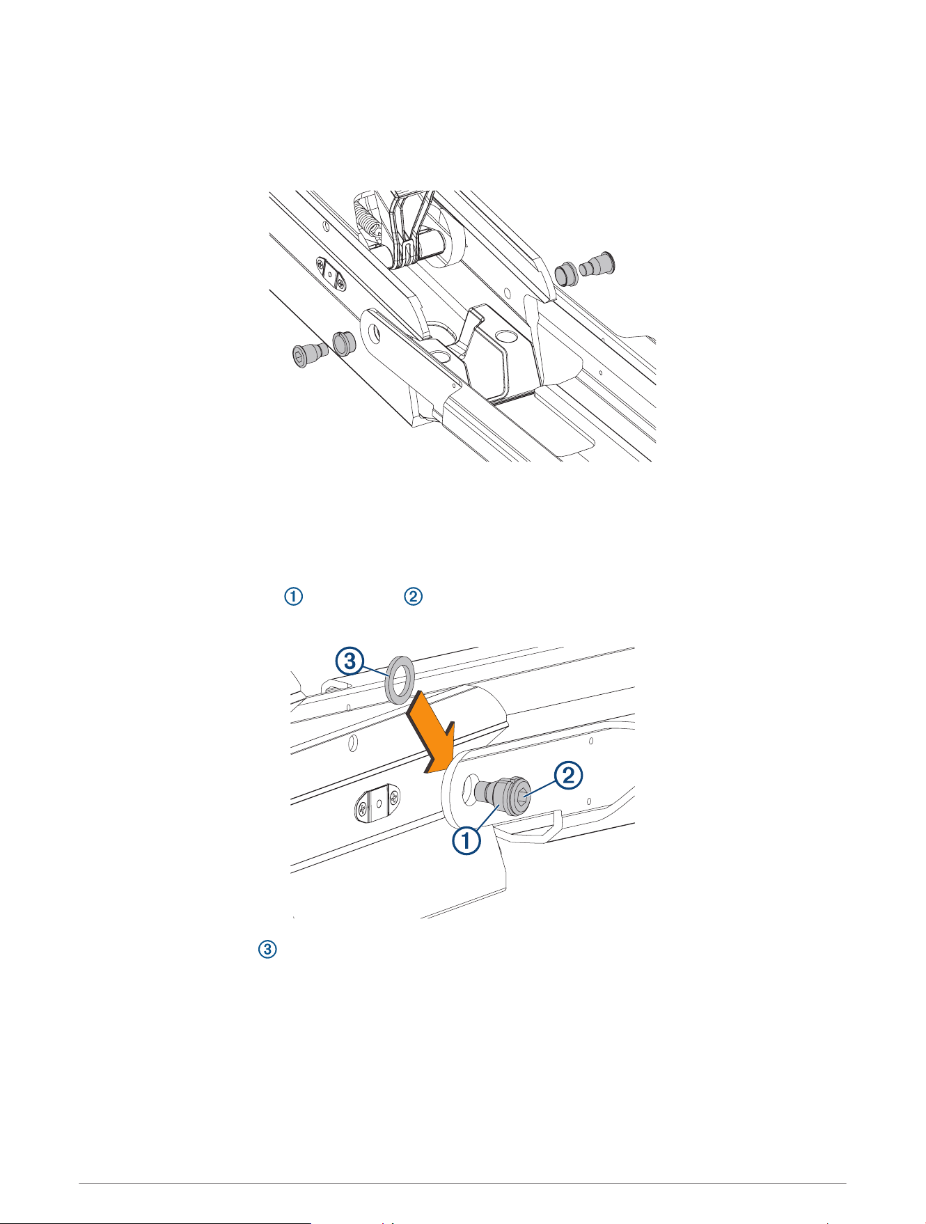
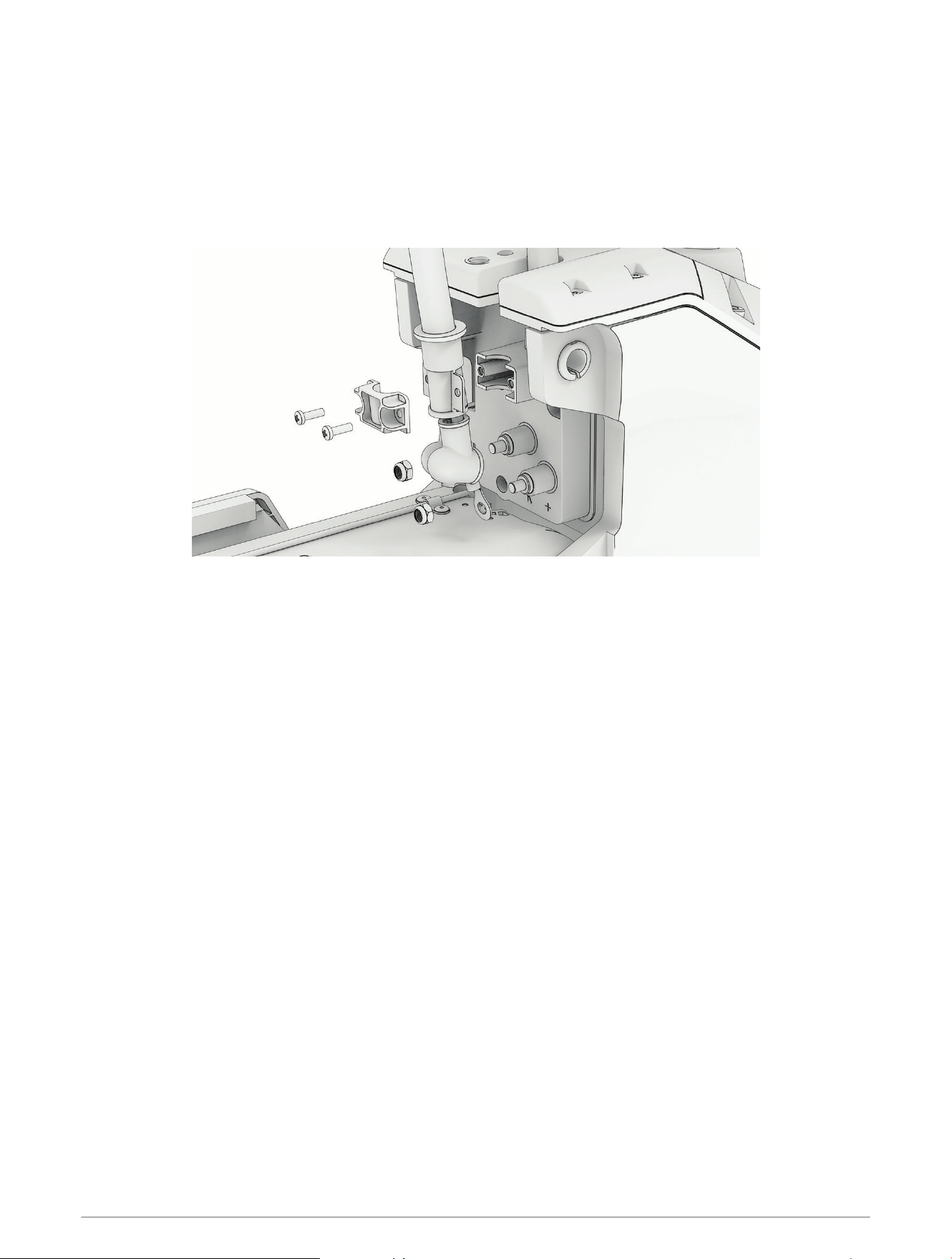
Removing the Upper Link from the Mount Base
Before you can remove the upper link from the mount base, you must disconnect the upper link from the
steering system (Disconnecting the Upper Link from the Steering System, page16).
1 Using an 8mm hex bit or wrench, loosen the two bolts that secure the upper link to the mount base.
TIP: The bolts that secure the upper link to the mount base are fastened very securely at the factory. You
may need to use a ratchet to hold the 8mm hex bit to provide the leverage needed to loosen these bolts.
2 Remove the bolts, bushings, and washers from both sides of the upper link.
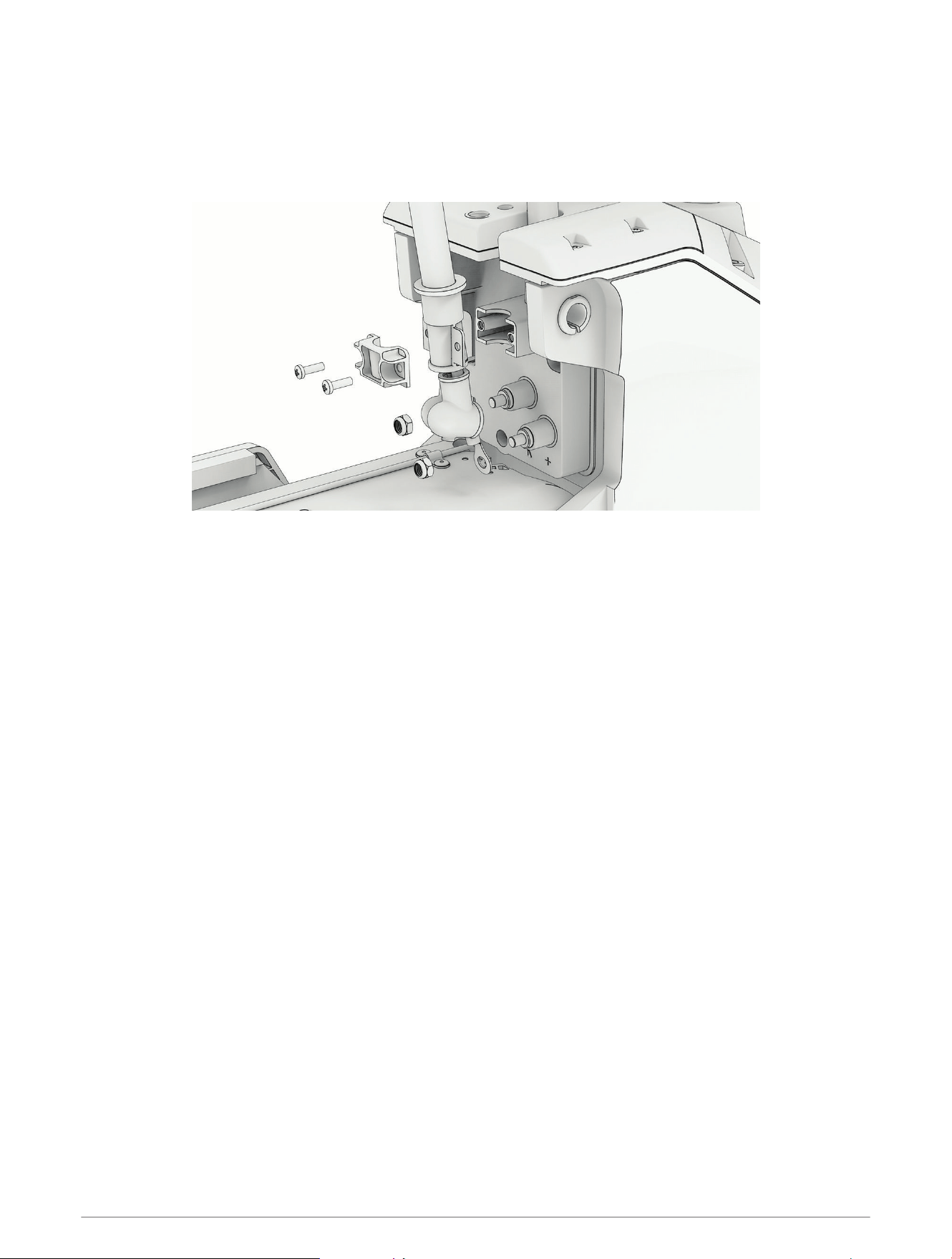
Reconnecting the Upper Link to the Mount Base
1 Place the plastic bushings over the bolts you removed with the original upper link, or over the two
bolts supplied with the replacement upper link.
2 Place a plastic washer that you removed with the original upper link or a washer supplied with the
replacement upper link between the upper link and the mount base.
NOTE: Replacement plastic washers may have adhesive on one side. If your washers have adhesive, you can
stick them to the mount base to make installing the bolts easier.
3 Push one of the bolts with a plastic bushing through the upper link and washer, and using an 8mm hex bit or
wrench, screw it into the mount base.
4 Repeat the previous step on the other side of the mount.
5 Tighten the bolts to 55Nm (40.5lbf-ft.).
Service Procedures 51
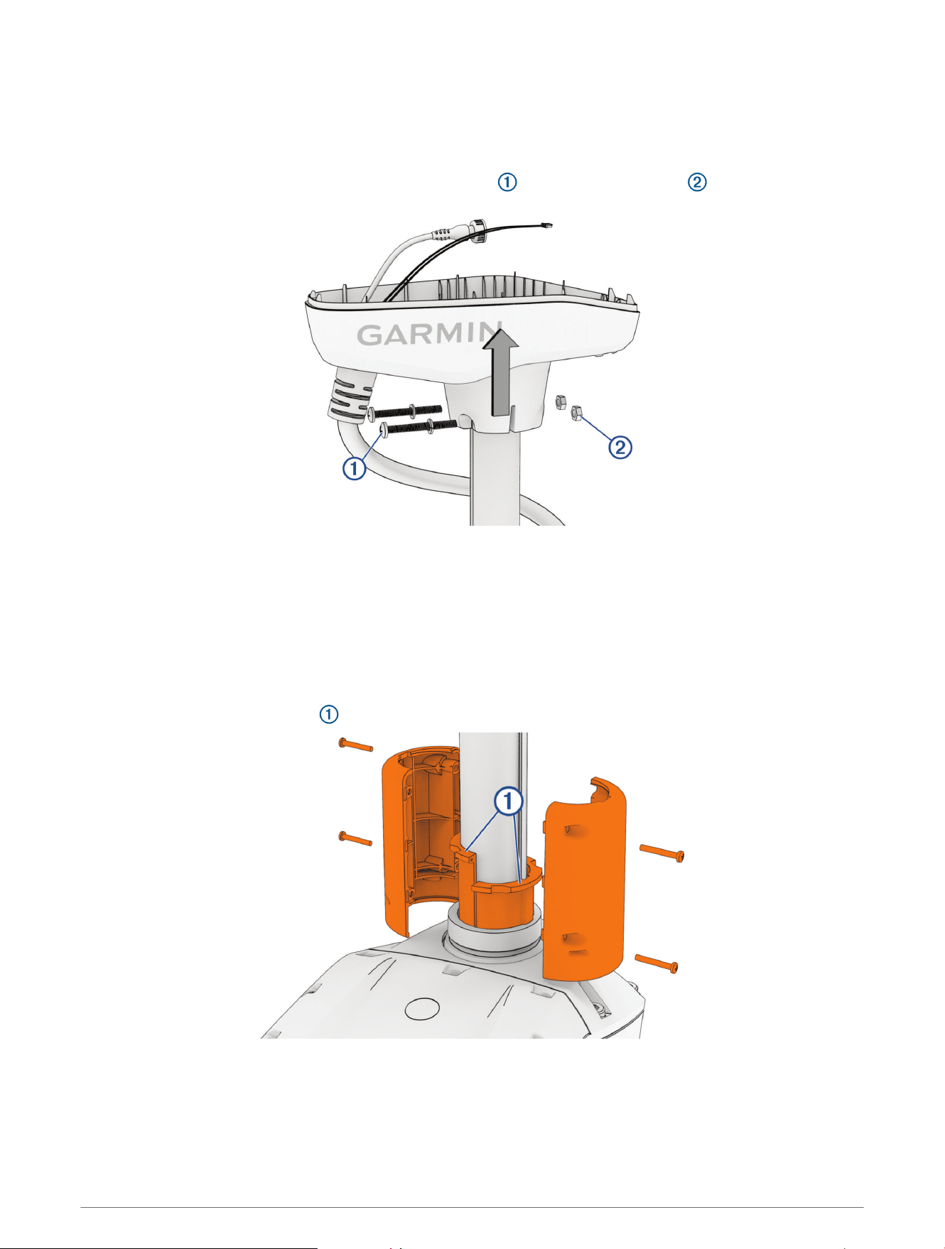
Removing the Lower Link from the Mount Base
Before you can remove the lower link from the mount base, you must remove the steering system from the
mount (Removing the Steering System from the Mount, page14).
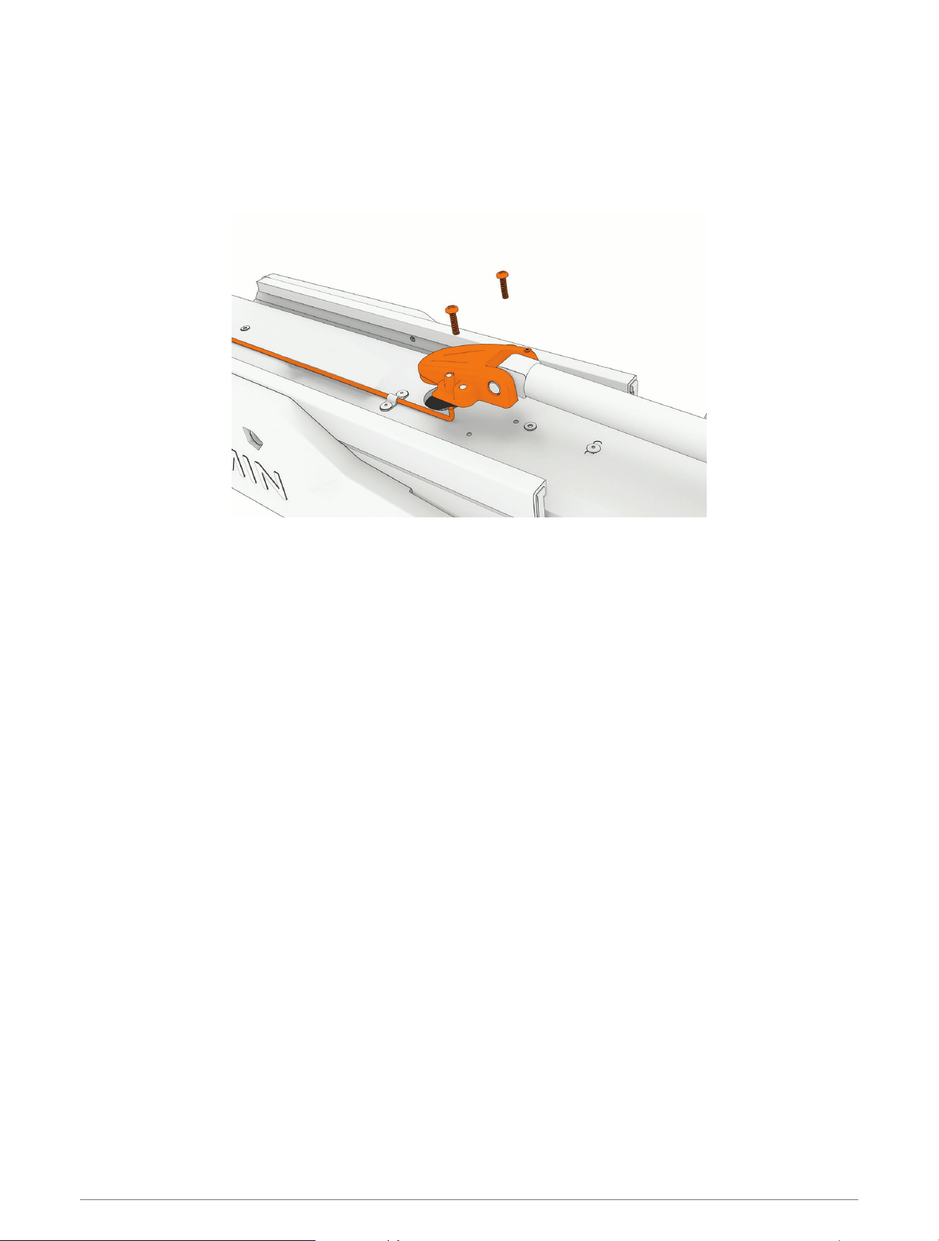
1 Pivot the lower link away from the mount base so you can access the latch spring.
2 Using needle-nose pliers, pull the spring to release it from the S-hook on the upper gas spring arm.
3 Release the latch spring from the latch mechanism inside the lower link, and set it aside.
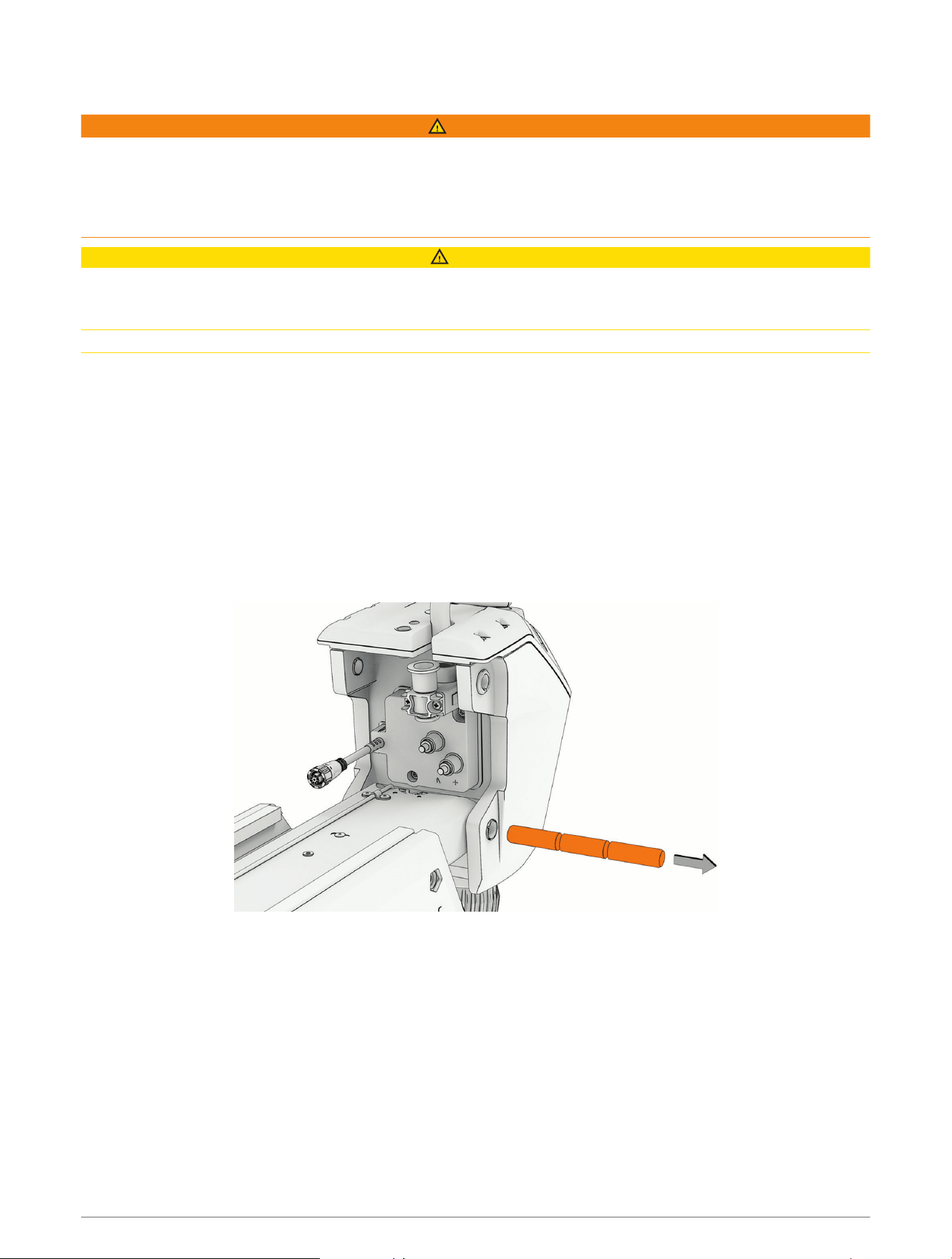
4 Using a #2 Phillips screwdriver, remove the covers from the sides of the mount base.
5 Push the pin out from one side and pull to remove it from the mount base.
6 Lift up to remove the lower link from the mount base.
52 Service Procedures
Installing the Lower Link to the Mount Base
1 If you are installing a new lower link, insert the latch release mechanism into the lower link and press until it
catches the screw head to hold it in place.
2 Make sure the bushings in the mount base are present. If necessary, insert them from the inside.
3 Line up the gas spring arms and the lower link with the hole in the mount base, and insert the hinge pin
securing all three components to the mount base.
You can insert the hinge pin through the mount base and the lower link, and align the gas spring arms one at
a time until the hinge pin is fully inserted.
4 Using a #2 Phillips screwdriver, reinstall the metallic covers over the ends of the hinge pin.
5 Pivot the lower link away from the mount base so you can access the latch mechanism.
Service Procedures 53
6 Place the S-hook on the upper gas spring arm.
7 Hook one end of the latch spring onto the link attached to the latch inside the lower link.
8 Using needle-nose pliers, pull the other end of the latch spring away from the lower link and hook it onto the
S-hook.
The latch spring pulls the latch mechanism and locks the lower link into the stowed position.
Replacing the Latch Mechanism in the Lower Link
Before you can replace the locking mechanism in the lower link, you must remove the lower link from the mount
base (Removing the Lower Link from the Mount Base, page52).
1 If necessary, remove the pull cable from the lower link (Removing the Pull Cable, page9).
2 Using needle-nose pliers, remove the cotter pins that secure the latch bars to the latch release rod.
NOTICE
Take note of the orientation of each cotter pin before you remove them. Reinstalling the cotter pins incorrectly
may cause damage to the latch mechanism.
54 Service Procedures
3 Slide the latch release rod out of either end of the lower link.
4 Slide the two latch bars out of the lower link.
NOTICE
Take note of the orientation of the latch bars before removing them. Installing the latch bars in the wrong
orientation interferes with the latch operation and may cause damage to the motor.
5 Apply a synthetic or marine grade, general-purpose grease to the replacement latch bars.
6 Insert the replacement latch bars into the lower link, following the correct orientation for the latches to lock
onto the mount base correctly.
7 Insert the replacement rod into either end of the lower link, feeding it in between the two sets of needle
rollers inside the lower link, and through the holes in the two latch bars.
8 Reinstall the cotter pins to secure the latch bars to the latch release rod.
NOTE: If you are installing new cotter pins from a service kit, you must use the cotter pins from bag A. The
pins in bag B are not used in theForce Pro trolling motor.
Replacing the Mount Base
1 Remove the steering system from the mount (Removing the Steering System from the Mount, page14).
2 Remove the upper link from the mount base (Removing the Upper Link from the Mount Base, page51).
3 Remove the lower link from the mount base (Removing the Lower Link from the Mount Base, page52).
4 Uninstall the fasteners that secure the mount base to the boat.
5 Secure the replacement mount base to the deck of the boat, replacing the existing mounting hardware if
necessary.
6 Install the lower link on the mount base (Installing the Lower Link to the Mount Base, page53).
7 Install the upper link on the mount base (Reconnecting the Upper Link to the Mount Base, page51).
8 Install the steering system on the mount (Connecting the Steering System to the Mount, page37).
Service Procedures 55
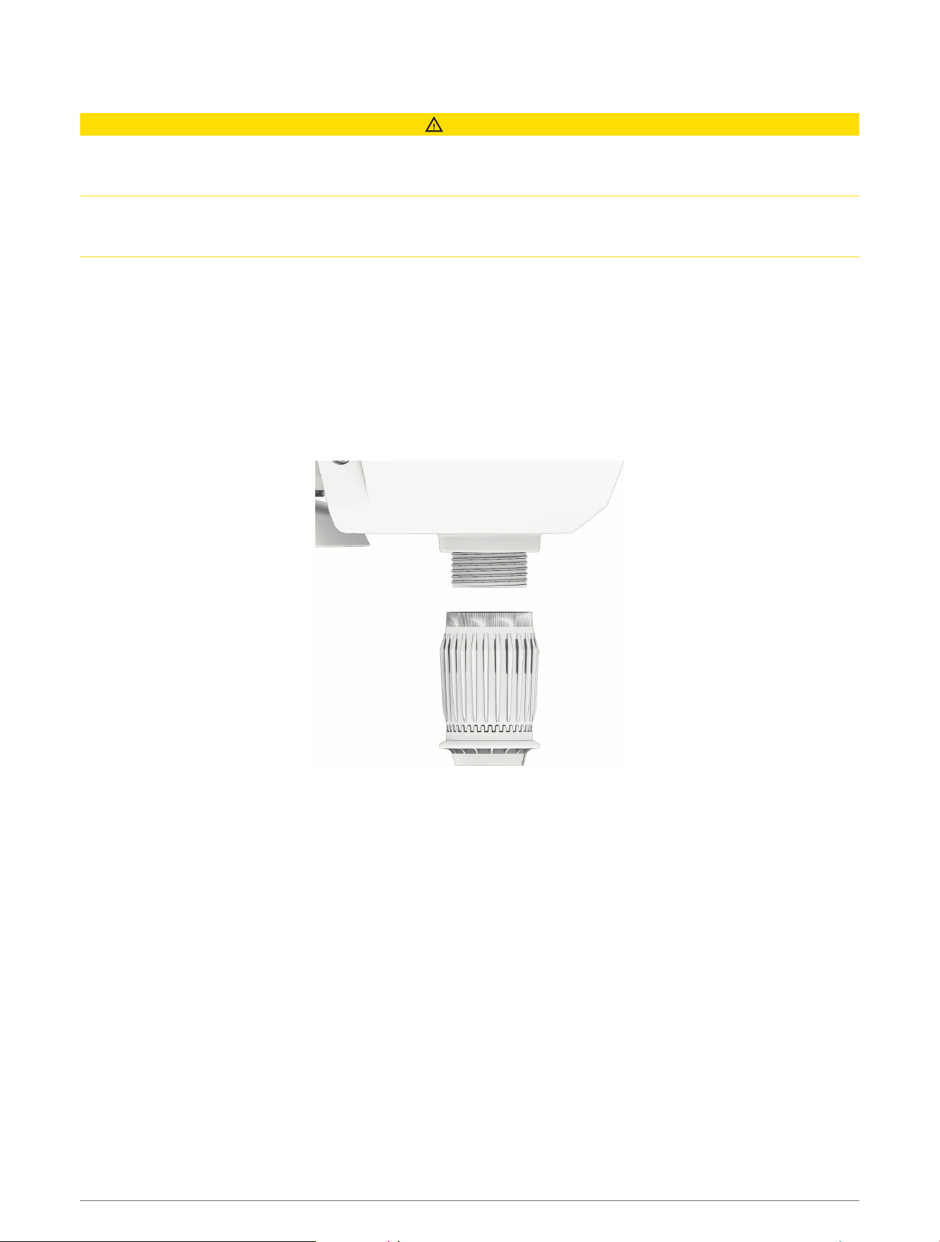
Replacing the Mount Shrouds
1 Using a 4 mm hex bit or wrench, remove the screws that secure the mount shrouds to the mount base.
2 Secure the replacement shrouds to the mount base using the screws provided with the replacement
shrouds.
Replacing the Mount Rails
Before you can replace the mount rails, you must remove the shrouds from the mount base (Replacing the
Mount Shrouds, page56).
1 Slide the two mount rails off of the mount base.
2 Slide the replacement rails onto the mount base.
3 Reinstall the shrouds.
56 Service Procedures
Replacing the Mount Bumper
1 Using a 4mm hex bit or wrench, remove the two screws that secure the mount bumper to the mount base.
2 Install the replacement mount bumper, and secure it to the mount base using the screws provided with the
replacement part.
Replacing the Stow Support
1 Using a 4mm hex bit or wrench, remove the screws securing the stow support to the mount base.
2 Install the replacement stow support using the screws provided with the replacement part.
Service Procedures 57
Removing the Electronics Cover
1 Using a T-10 TORX screwdriver, remove the eight screws that secure the electronics cover to the steering
system housing.
2 Lift up and remove the electronics cover.
Reinstalling the Electronics Cover
1 If necessary, replace the rubber seal on the bottom of the electronics cover.
2 Place the electronics cover on the steering system housing.
3 Using a T-10 TORX screwdriver, install the eight screws that secure the electronics cover to the steering
system housing.
4 Tighten the screws to 0.7 N-m (6 lbf-in).
58 Service Procedures
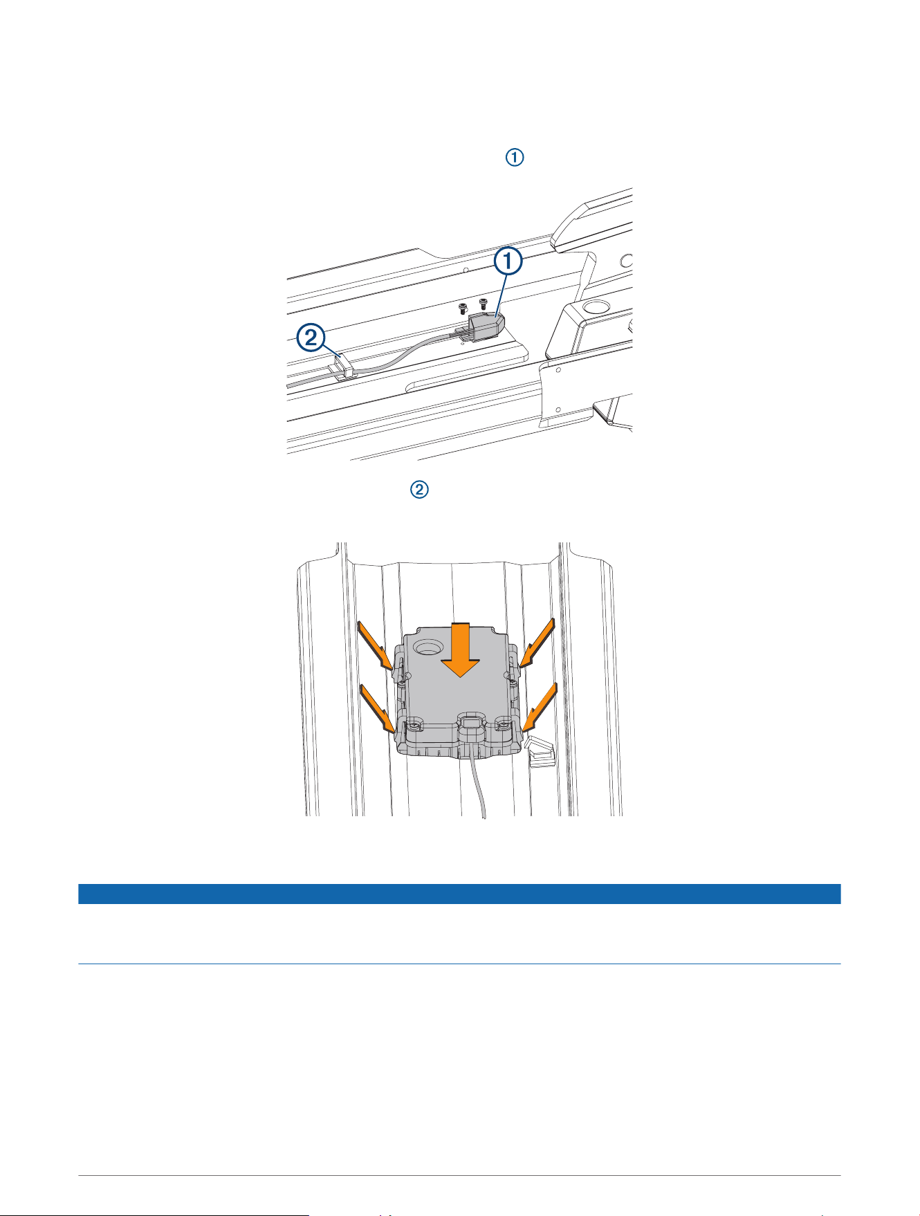
Replacing the PCB
1 Remove the coil cable from the steering system housing (Removing the Coil Cable from the Steering System,
page48).
2 Open the electronics cover (Removing the Electronics Cover, page58).
3 Carefully remove the tape covering the connectors.
This tape is required during reassembly.
4 Disconnect the three wire harnesses from the PCB.
NOTICE
Use extreme care when disconnecting and reconnecting the wire harnesses to the PCB to avoid damage to the
cables and connectors.
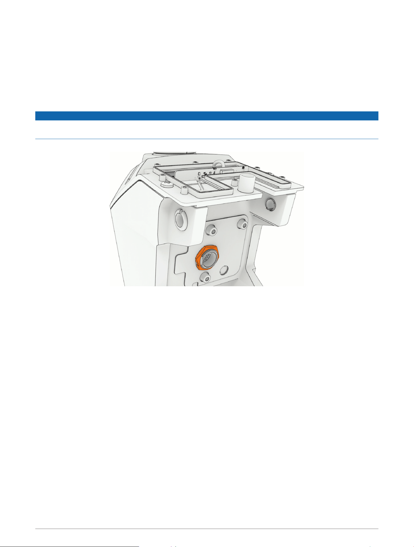
5 Using a 29mm wrench or socket, remove the nut on the electronics connector.
6 Remove the PCB by lifting it up and out of the steering system housing.
7 Install the circular gasket on the connector that feeds through the steering system housing.
8 Place the replacement PCB into the steering system housing, feeding the electronics connector through the
hole.
9 Secure the replacement PCB to the steering system housing using the nut you removed in the previous step.
10 Reconnect the three wire harnesses to the PCB.
11 Place the tape you removed from the original PCB over the connectors on the replacement PCB.
12 Reinstall the electronics cover (Reinstalling the Electronics Cover, page58).
Service Procedures 59
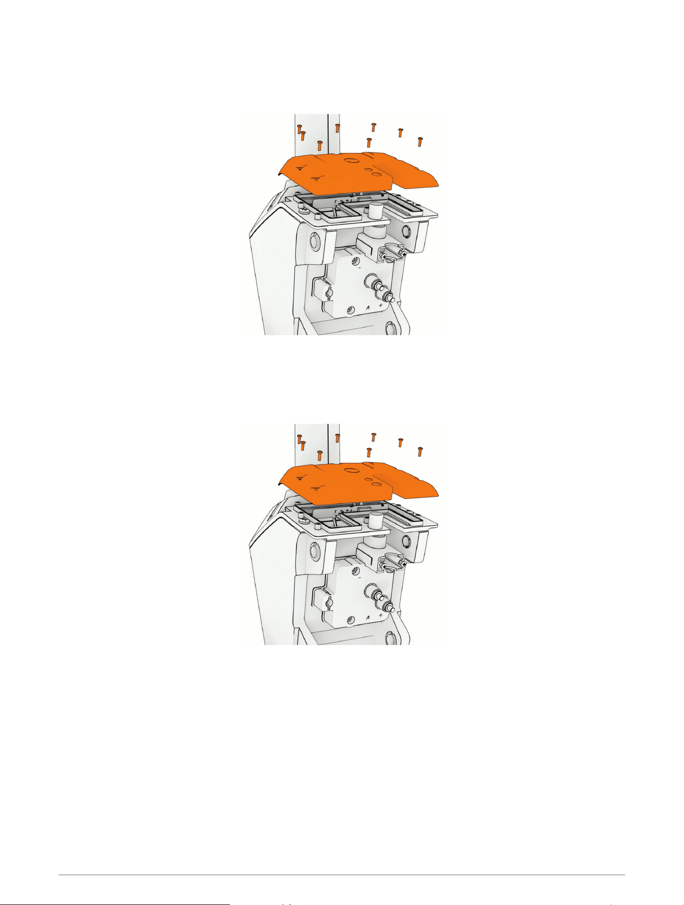
Opening the Steering System Housing
1 Remove the shaft from the steering system (Removing the Shaft, page23).
2 Remove the steering system from the mount (Removing the Steering System from the Mount, page14).
3 Remove the depth-adjustment collar (Removing the Depth-Adjustment Collar, page23).
4 Remove the electronics cover (Removing the Electronics Cover, page58).
5 Remove the PCB (Replacing the PCB, page59).
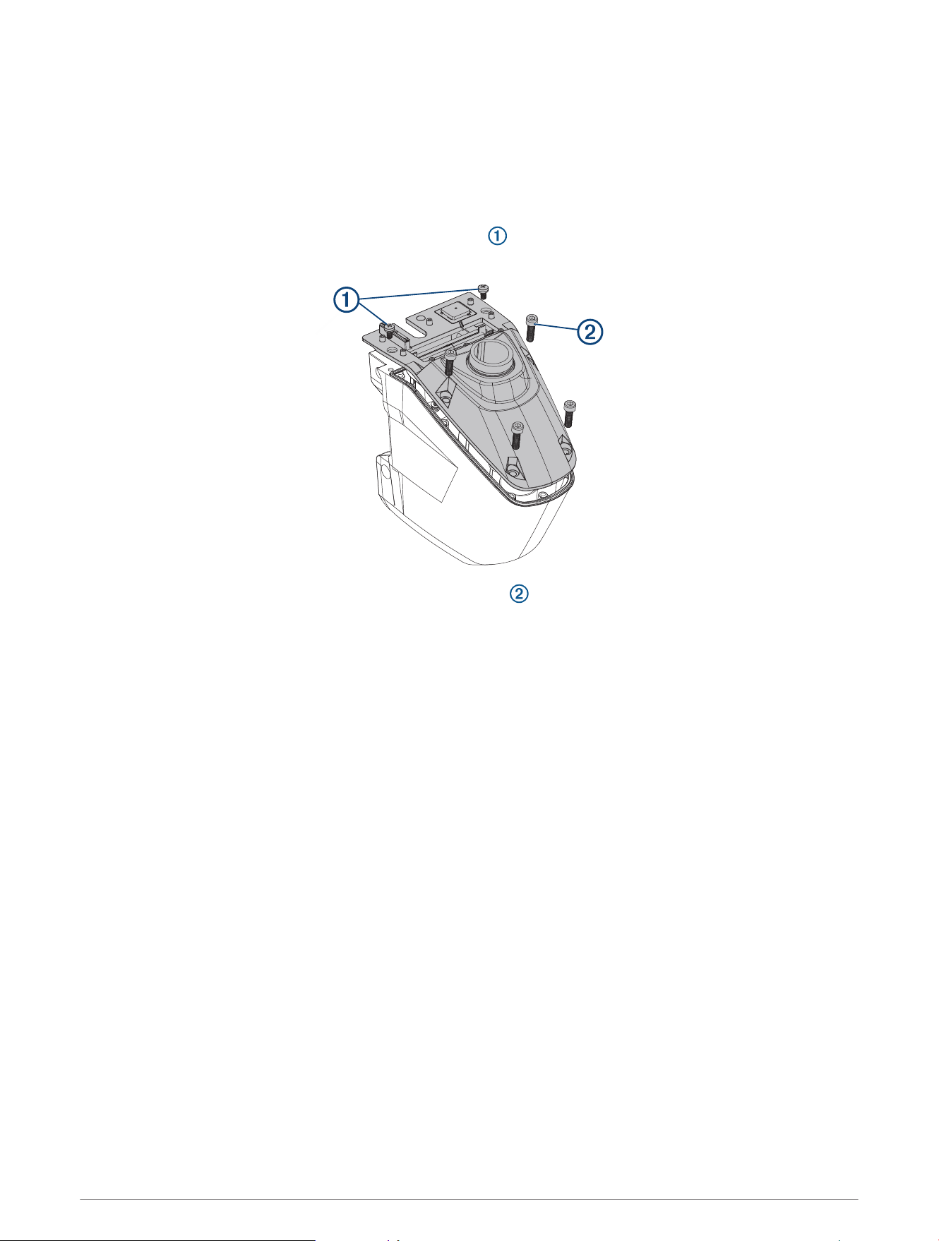
6 Using a #3 Phillips screwdriver, remove the two screws and washers on the top of the steering system
housing.
7 Using a 6mm hex bit or wrench, remove the four hex bolts and nylon washers on the top of the steering
system housing.
8 Turn over the steering system housing.
9 Lift up carefully and evenly on the base of the steering system housing to separate the two parts.
60 Service Procedures
Closing the Steering System Housing
1 Apply a light layer of synthetic or marine grade, general-purpose grease to the black rubber seal around
the shaft-carrier opening in the steering system housing.
2 Set the top of the steering system on a table or workbench with the shaft carrier and servo motor pointing
up.
3 Make sure the gasket is installed in the groove around the perimeter of the upper steering system
housing.
4 Place the bottom of the steering system housing over the shaft carrier, and lower it onto the top of the
steering system housing.
NOTE: You may need to start by connecting the back parts of the housing first, and rotate the front of the
housing into place.
5 Keeping the steering system upside down, install one or two of the screws to hold the parts together.
6 Turn the steering system over, and install the rest of the screws.
7 Tighten all of the screws to 5N-m (43lbf-in).
Service Procedures 61
Removing the Steering Servo Motor and Shaft Carrier
Before you can remove the steering servo motor, you must open the steering system housing (Opening the
Steering System Housing, page60).
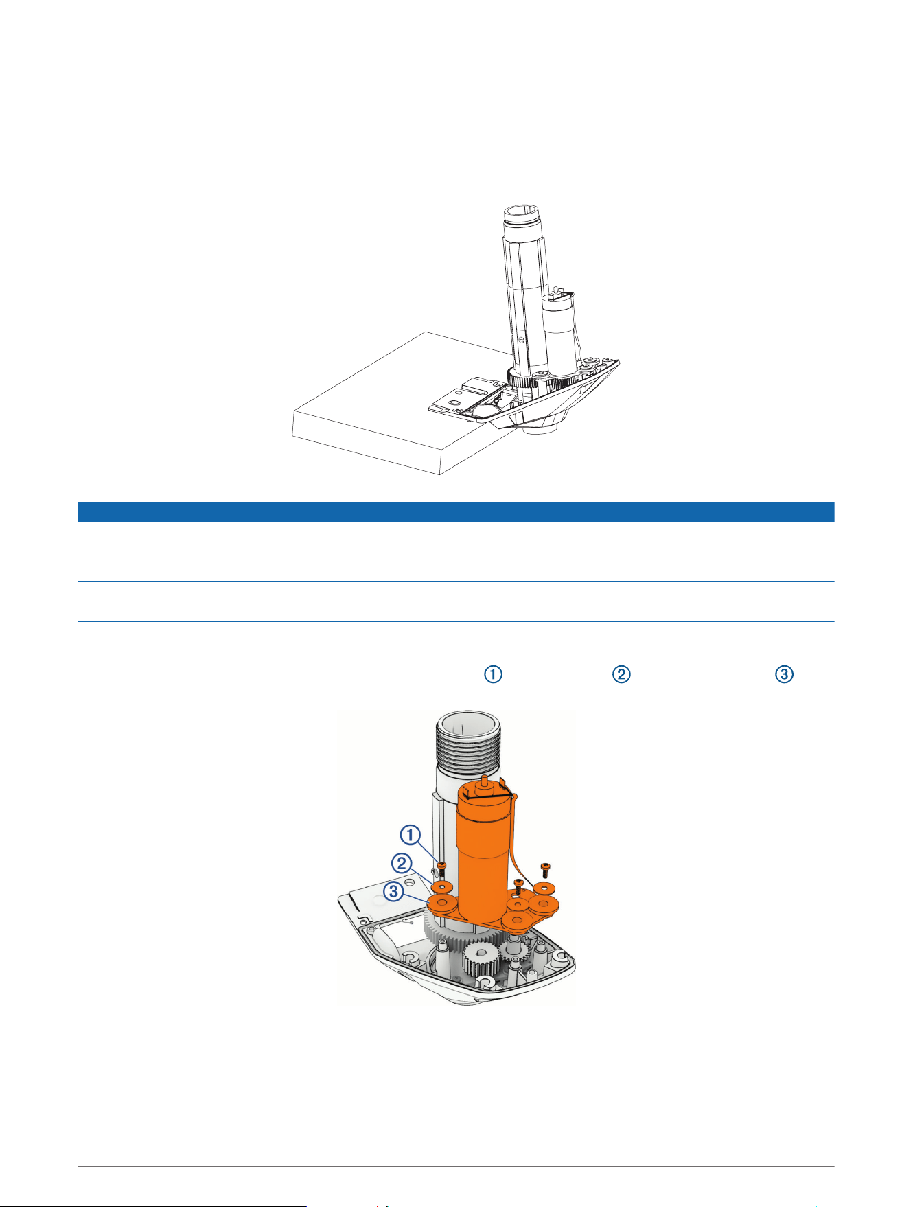
1 Support the top of the steering system housing on the edge of a bench or a table and not on the top of the
shaft carrier.
NOTICE
The steering servo motor bracket is the main component holding the steering assembly together. If you set the
assembly on a table so that the shaft carrier bears the weight of the assembly, the top of the steering system
housing may suddenly fall down, shifting the assembly components and potentially causing product damage.
Do not clamp the edge of the housing to a bench or table to support it. Clamping may damage the coating or
bend the housing.
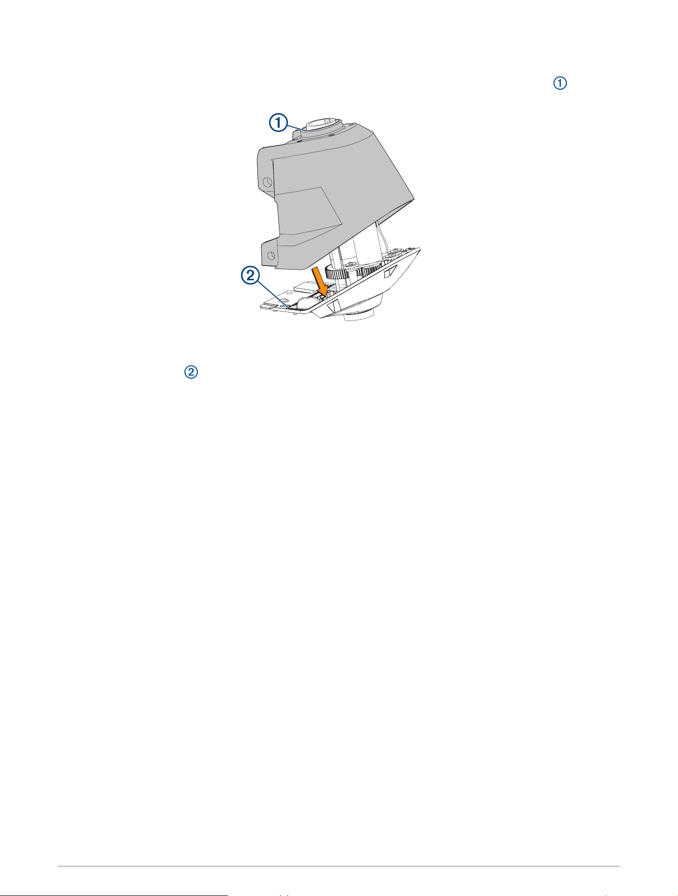
2 Using a #2 Phillips screwdriver, remove the clip that secures the motor and steering position sensor cables
to the housing.
3 Using a #2 Phillips screwdriver, remove the three screws , metal washers , and rubber washers that
secure the steering servo motor to the housing.
62 Service Procedures
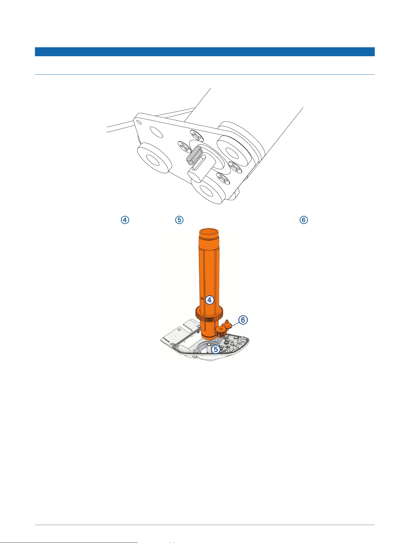
4 Lift up and remove the steering servo motor from the housing.
NOTICE
The key in the steering servo motor shaft may fall out of its keyseat when you lift the motor or pull the drive gear
off the motor shaft. Take care to save this key.
5 Remove the shaft carrier , the drive gear and the steering position sensor gear and set them aside.
NOTE: The metal drive gear may have adhered to the motor shaft when you removed the motor. If necessary,
you can pull the drive gear off the motor shaft to remove it.
Service Procedures 63
Reinstalling the Steering Servo Motor and Shaft Carrier
NOTICE
If you are installing the steering servo motor with a new shaft carrier and new steering system gears, you must
apply lubrication according to the instructions below. Installing a new shaft carrier and steering system gears
without the proper lubrication will lead to product damage.
1 If necessary, apply a light layer of silicone grease to the black rubber seal around the shaft-carrier opening in
the steering system housing.
2 Place the shaft carrier into the upper steering system housing.
3 Place the plastic gear into the hole on the steering position sensor bracket near the edge of the steering
system housing.
4 If necessary, apply a generous amount of silicone grease to the shaft carrier gear.
5 Make sure the key is fully seated in the keyseat in the steering servo motor shaft.
6 If necessary, apply synthetic or marine grade, general-purpose grease to the metal drive gear.
7 Install the drive gear onto the steering servo motor shaft, lining up the key in the shaft with the keyway in the
drive gear.
8 Place the steering servo motor in the steering system housing, lining it up with the shaft carrier gear.
NOTE: You must support the steering system housing on the edge of a bench or table so that the shaft
carrier can be fully seated when you reinstall the steering servo motor. If the shaft carrier is not fully seated
in the housing, the drive gear and servo motor cannot line up correctly with the shaft carrier gear, and you will
not be able to install the servo motor.
64 Service Procedures
9 Secure the steering servo motor to the top of the steering system housing using the three screws, metal, and
rubber washers.
10 Tighten the three screws to 1N-m (8.7lbf-in).
11 Using a #2 Phillips screwdriver, install the clip that secures the motor and steering position sensor cables to
the housing.
12 Close the steering system housing (Closing the Steering System Housing, page61).
Replacing the Steering Position Sensor
Before you can replace the steering position sensor, you must remove the steering servo motor, shaft carrier
and gears (Removing the Steering Servo Motor and Shaft Carrier, page62).
1 Using a #2 Phillips screwdriver, remove the three screws that secure the steering position sensor to the
steering system housing.
2 Lift up and remove the steering position sensor.
3 Install the replacement steering position sensor using the screws provided with the replacement sensor.
4 Tighten the screws to 1N-m (8.7lbf-in)
Service Procedures 65

support.garmin.com
GUID-4961C943-E6C7-423B-AC7D-40EC5C713247 v1March 2025