FORCE
®
AND FORCE PRO TROLLINGMOTOR STABILIZER
INSTALLATION INSTRUCTIONS
Getting Started
WARNING
See the Important Safety and Product Information guide in the product box for product warnings and other
important information.
CAUTION
To avoid possible personal injury, always wear safety goggles, ear protection, and a dust mask when drilling,
cutting, or sanding.
NOTICE
When drilling or cutting, always check what is on the opposite side of the surface to avoid damaging the vessel.
You must install the stabilizer to reduce the risk of damage to the trolling motor mount and to the vessel while
driving in rough conditions or trailering.
Tools Needed
• 9/16in. (14mm) wrench or socket
• 3/16in. hex bit or wrench
• Torque wrench
• Hacksaw or similar cutting tool to trim the length of the stabilizer (optional)
Installation Procedures
NOTICE
When assembling the motor, you must use hand tools to install all of the parts, observing the torque
specifications when provided. Using power tools to assemble the motor may damage the components, and
voids the warranty.
GUID-051D8638-DDC1-49A4-B3D4-01965932DFB4 v3March 2025
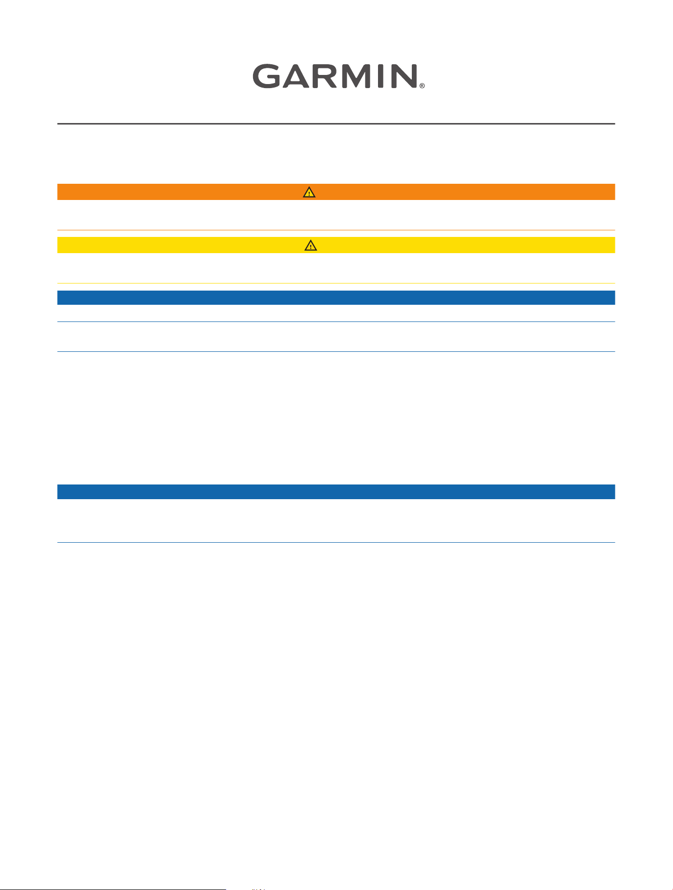
Attaching the Bracket
1 Transition the motor into the stowed position.
2 With the folded portion of the bracket facing the steering system housing , place the bracket on either
the port or the starboard side of the motor steering housing.
NOTE: If you install the bracket with the folded portion facing away from the steering system housing, the
stabilizer rod will contact the gunwale and prevent the motor from locking in the deployed position.
3 Loosely attach the bracket to the motor steering housing using the included bolts and washers.
4 Push the bracket up to rotate it until the bolts contact the outer edge of the top mounting hole and the
inner edge of the bottom mounting hole , and tighten the bolts to 20lbf-ft. (27N-m).
NOTE: If you secure the bracket without first pushing it up to rotate it, you may be unable to install the
stabilizer rod in the appropriate angle for it to contact the surface under the motor and to allow for the proper
clearance when stowing the motor.
2
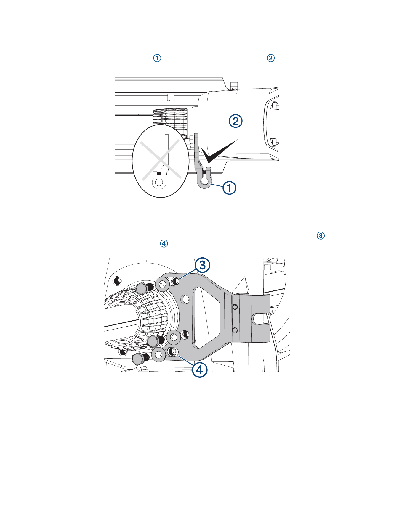
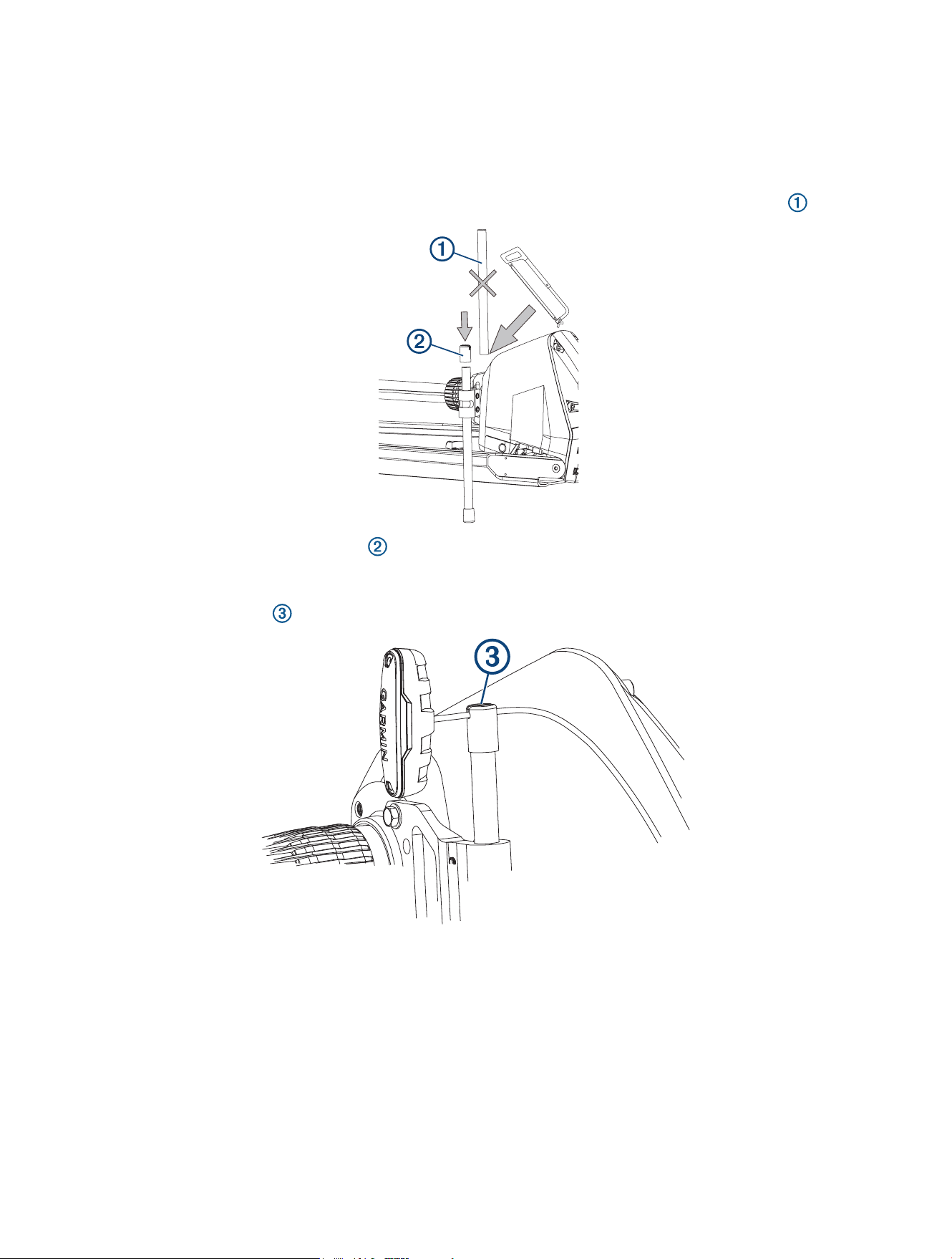
Installing the Stabilizer Rod
1 Place the stabilizer rod into the bracket.
2 Place the bumper cap onto the lower end of the rod.
NOTE: Two caps are included with the stabilizer. The notched cap fits over the top of the rod and allows you
to store the pull handle when it is not in use. You should install the notched cap on the top after you have
trimmed the rod in a later step.
3 Apply light pressure to the top of the rod, and use a
3
/
16
in. hex bit or wrench to tighten the bolts and
secure the rod in the bracket.
CAUTION
You must apply only light downward pressure while installing the stabilizer rod. If you install the rod with too
much pressure, it will be difficult to engage the motor latch properly in the stowed position, which could cause
an accidental deployment leading to possible personal injury or property damage.
4 Move the motor between the stowed and deployed position to test for stabilizer-rod clearance and proper
support.
5 Repeat steps 3 and 4 until the motor transitions smoothly between the stowed and deployed positions, and
the stabilizer provides proper support when in the stowed position.
3
Trimming the Stabilizer Rod
Before you trim the stabilizer rod, you must install the rod and test the installation for clearance and proper
support.
Trimming the height of the stabilizer rod is optional. If you decide to use the rod at its full length, proceed to the
final step to install the upper cap.
1 Using a hacksaw or similar cutting tool, remove the desired excess length from the top of the rod .
2 Place one of the included upper caps on top of the rod to complete the installation.
NOTE: You should test the included upper caps on your pull cable and select the one with the groove that
best fits the thickness of the pull cable on your trolling motor.
You can use the groove in the upper cap on the stabilizer rod to hold the pull cable when it is not in use.
© 2024 Garmin Ltd. or its subsidiaries
Garmin
®
, the Garmin logo, and Force
®
are trademarks of Garmin Ltd. or its subsidiaries, registered in the USA and other countries. These trademarks may not be used
without the express permission of Garmin.
© 2024 Garmin Ltd. or its subsidiaries
support.garmin.com
