
FORCE
®
KRAKEN TROLLING MOTOR STABILIZER
INSTALLATION INSTRUCTIONS
Getting Started
WARNING
Always disconnect the trolling motor from the battery before performing service.
CAUTION
To avoid possible personal injury, always wear safety goggles, ear protection, and a dust mask when drilling,
cutting, or sanding.
NOTICE
When drilling or cutting, always check what is on the opposite side of the surface to avoid damaging the vessel.
This is an optional accessory that can help stabilize and provide additional support for the trolling motor when it
is in the stowed position.
Tools Needed
• #2 Phillips screwdriver
• Hacksaw or similar cutting tool to trim the length of the stabilizer
• 6 mm (
7
/
32
in.) hex bit or wrench
• 5 mm (
3
/
16
in.) hex bit or wrench
• 4 mm (
5
/
32
in.) hex bit or wrench
• Power drill
• 6.25mm (
1
/
4
in.) drill bit
• 3mm (
1
/
8
in.) drill bit
GUID-4CC767E4-9B69-4A32-B774-CE033285B670 v1July 2023
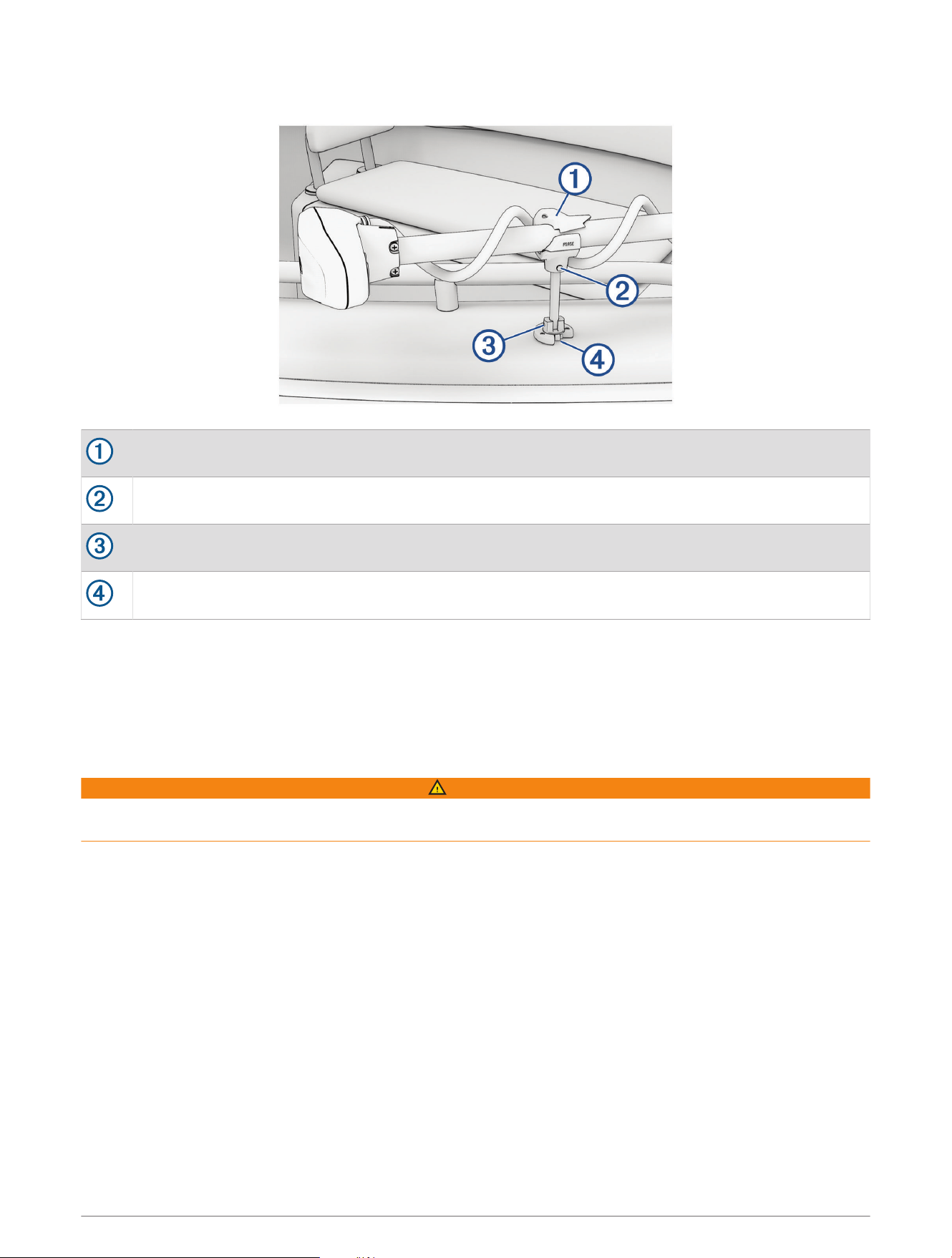
Device Overview
Shaft clamp. Rotate to lock the shaft in place.
Shaft clamp bolt.
Swivel mount base 6 mm swing tension bolt. Adjust to set swing tension.
Swivel mount base 4 mm swivel tension bolt. Adjust to set swivel tension.
Installation Procedures
Trimming the Stabilizer Rod
Before you trim the stabilizer rod, you must test the installation location for object clearance and proper support
of the trolling motor shaft.
NOTE: Some users may not need to trim the stabilizer.
WARNING
To avoid possible serious personal injury while cutting with a saw or similar tool, wear protective gloves, use
care, and keep all hands and other body parts away from the blade and cutting area.
1 With the motor in the stowed position, place the stabilizer swivel mount base adjacent to the mounting
location, and observe where the rod contacts the downshaft of the motor.
2 Measure
1
/
2
in. (12.7 mm) below the point where the stabilizer rod contacts the downshaft of the motor, and
mark the location on the rod.
3 Deploy the motor to move it out of the way.
4 Using a hacksaw or similar cutting tool, cut the rod at the marked location to remove the excess length from
the top of the rod.
5 Place the clamp on the end of the rod you cut in the previous step and mark the location for the bolt
passthrough hole.
2
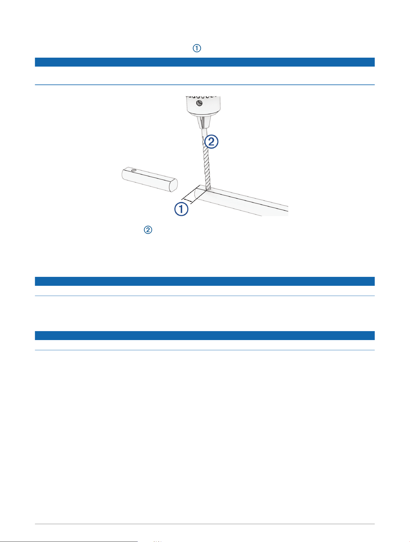
6 Remove the clamp from the rod.
The marked location should be 15 mm (
19
/
32
in.) from the cut.
NOTICE
Drilling the passthrough hole through the clamp may damage the clamp. You can use the cut-off portion of the
stabilizer rod as a drill guide or template.
7 Using a 6.25mm (
1
/
4
in.) drill bit , drill a hole in the rod to secure the shaft clamp.
8 Install the shaft clamp, bolt, and nut.
Installing the Swivel Mount Base
1 Place the swivel mount base in the mounting location with the trolling motor stowed.
NOTICE
The swivel mount base must be installed centered directly below the motor shaft.
2 Ensure the location is suitable for moving the motor and does not interfere with motor or vessel operation.
3 Deploy the motor to move it out of the way.
4 Mark the mounting holes for the swivel mount base and remove the swivel mount base.
NOTICE
To avoid damaging the swivel mount base, do not drill though the base.
5 Using a 3 mm (
1
/
8
in.) drill bit, drill one pilot hole.
6 Loosely fit the swivel mount base using one screw to ensure the other two marks are properly located, and
make new marks if necessary.
7 Drill the remaining two pilot holes.
8 Secure all of the screws to install the swivel mount base.
9 Adjust the swivel and swing tension bolts to the preferred tension settings.
3
Securing the Stabilizer
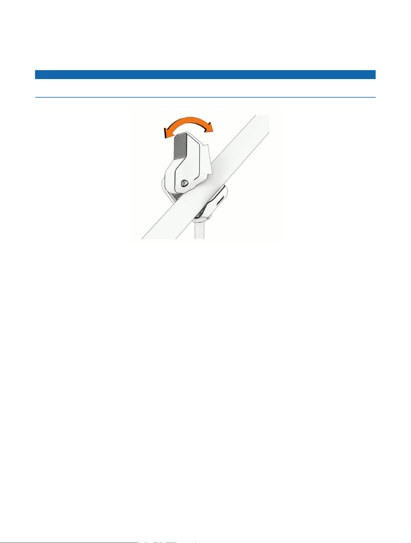
1 Place the trolling motor into the stowed position.
2 Lift the stabilizer up to meet the trolling motor shaft.
NOTICE
To prevent possible damage to the cabling, avoid clamping the power or transducer cable in the clamp with the
motor shaft.
3 Cradle the trolling motor shaft in the stabilizer and rotate the clamp over the shaft to hold it in place.
© 2023 Garmin Ltd. or its subsidiaries
Garmin
®
, the Garmin logo, and Force
®
are trademarks of Garmin Ltd. or its subsidiaries, registered in the USA and other countries. These trademarks may not be used
without the express permission of Garmin.
LOCTITE
®
is a trademark of Henkel Corporation in the U.S. and elsewhere.
© 2023 Garmin Ltd. or its subsidiaries
support.garmin.com