
FORCE
®
KRAKEN TROLLING MOTOR LIVESCOPE
™
BRACKET
INSTALLATION INSTRUCTIONS
Important Safety Information
WARNING
See the Important Safety and Product Information guide in the product box for product warnings and other
important information.
Always disconnect the trolling motor from the battery before performing any service.
You are responsible for the safe and prudent operation of your vessel. Sonar is a tool that enhances your
awareness of the water beneath your boat. It does not relieve you of the responsibility of observing the water
around your boat as you navigate.
CAUTION
Failure to install and maintain this equipment in accordance with these instructions could result in injury,
damage to the product and/or vessel, or poor product performance.
Read all installation instructions before proceeding with the installation. If you experience difficulty during the
installation, go to support.garmin.com for more information.
Tools Needed
• #2 Phillips screwdriver
• 2.5 mm allen wrench (included)
• 5 mm allen wrench (included)
• 6 mm allen wrench (included)
• Diagonal pliers
• Electrical tape
• Zip ties
• Grommet wrench (included)
• Marine grease (included)
• Torque wrench
GUID-9EAA0430-70F9-4795-82EB-AB34895E5623
v3
August 2024
Mounting Considerations
NOTICE
To avoid possible damage to the trolling motor and transducer, and to ensure proper functionality, you must use
only the hardware included in this kit. The included bolts may not be the same as bolts that came with your
LiveScope transducer, and using the incorrect bolts may result in product damage and failure.
• You should mount the LiveScope transducer where it will not interfere while stowing the trolling motor.
• You may mount your LiveScope transducer on either the starboard side or the port side of your trolling motor
shaft.
• Once the LiveScope transducer is mounted, the motor can only stow in one direction. Choose which side you
want the propeller to face when stowed, because it cannot be changed after installation.
NOTE: You may need to adjust the trolling motor stow side. See the Force Kraken Trolling Motor Owner's
Manual for instructions.
• After installation, you can set the LiveScope transducer to the preferred viewing mode.
• Firmly tighten all LiveScope transducer bracket adjustment knobs before each use.
Refer to the LiveScope transducer instructions for more information about connecting, mounting and securing
the LiveScope transducer cable after installation.
Installing the Transducer on a Trolling Motor
Opening the Shaft Cap
WARNING
Before you open the shaft cap, you must disconnect the motor from the power source. Failure to disconnect the
power source can lead to electrical shock or damage to the motor.
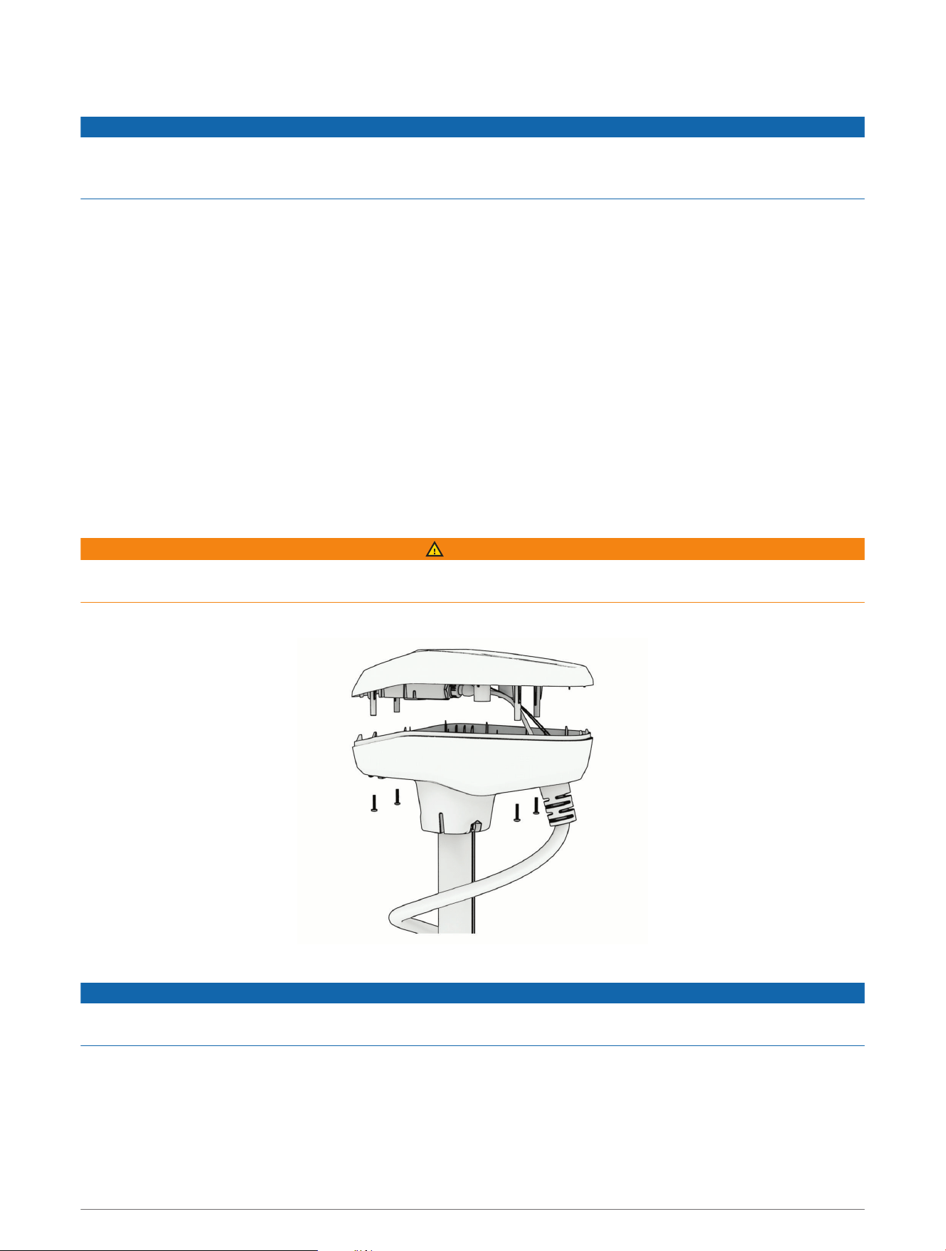
1 Using a #2 Phillips screwdriver, remove the four screws that secure the lid of the shaft cap.
2 Carefully lift up the lid of the shaft cap to access the cable connectors inside.
NOTICE
There are two cables connected to the top of the shaft cap. Take care when opening the shaft cap to avoid
damaging the cables or connectors.
2
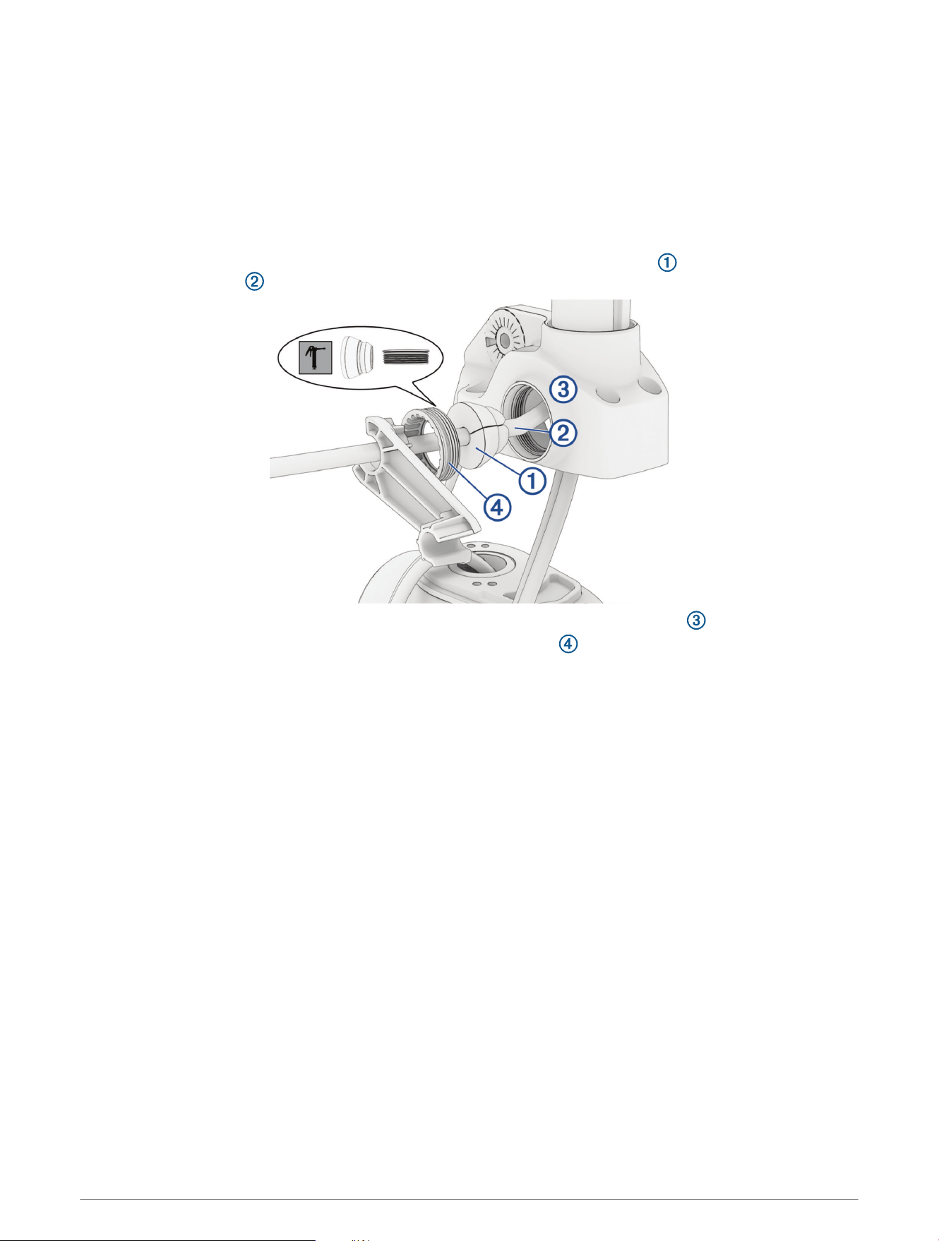
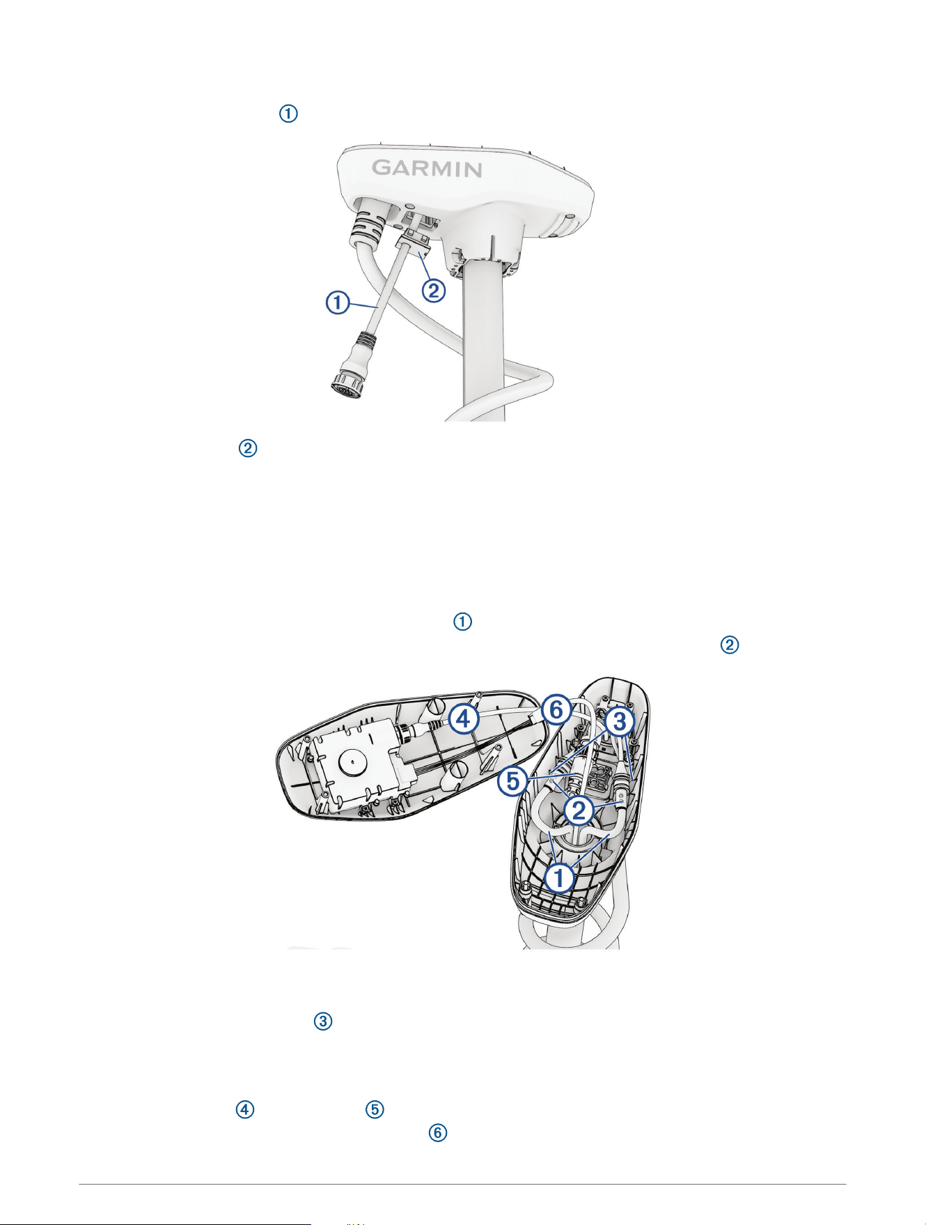
Disconnecting the Cables in the Shaft Cap
Before you can disconnect the cables in the shaft cap, you must open the shaft cap (Opening the Shaft Cap,
page2).
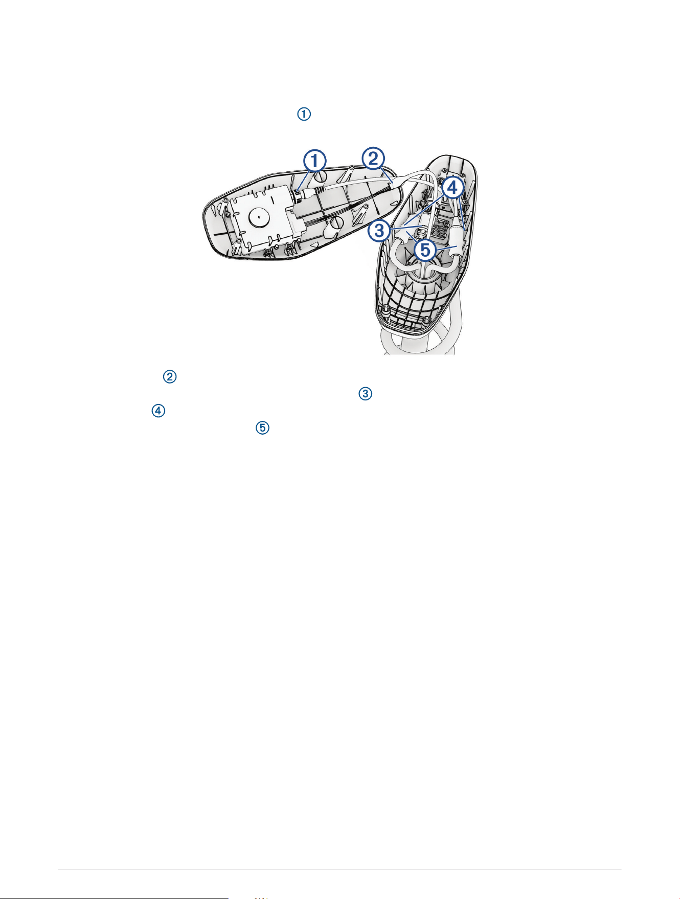
1 Unscrew and disconnect the USB connector .
Ensure the o-ring remains in place inside the connector.
2 Release the latch and pull the connectors apart to disconnect the data cable.
3 If present, unscrew and disconnect the transducer cable , and cut off the locking ring.
4 Cut the zip ties .
5 Slide down the protective coverings on the power cables.
6 Using a 2.5 mm allen wrench, loosen the four set screws on the two power cables.
7 Disconnect the power cables.
8 Remove the protective coverings from the power cables.
3
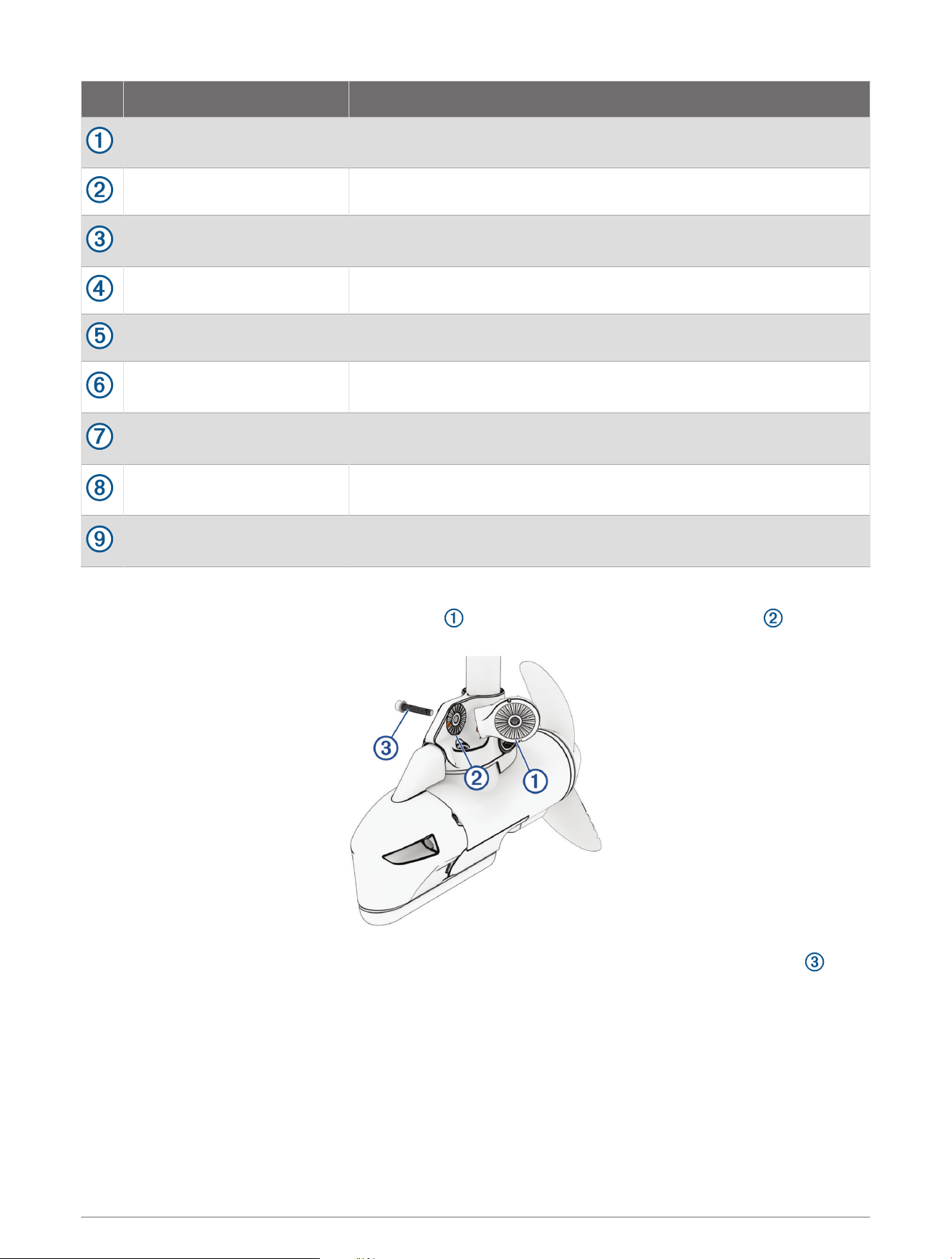
Removing the Skeg and Nose Cone
1 Using a 4mm hex bit or wrench, remove the four screws that secure the skeg to the propeller drive
motor.
2 Remove the skeg.
3 Using a 4mm hex bit or wrench, remove the two screws that secure the front of the nose cone to the
propeller drive motor.
4 Using a 3mm hex bit or wrench, remove the single screw that secures the bottom of the nose cone to the
propeller drive motor.
NOTE: You should keep all of these screws and parts in a safe place, because you must reinstall them when
reassembling the skeg and nose cone.
4
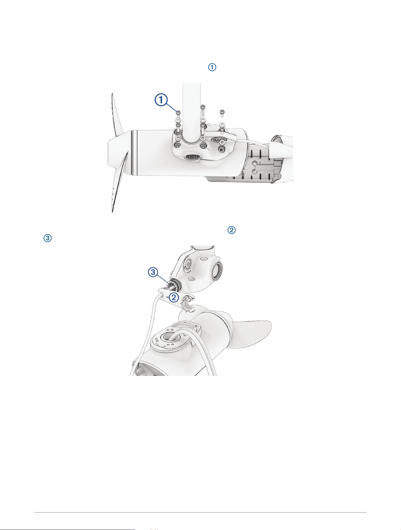
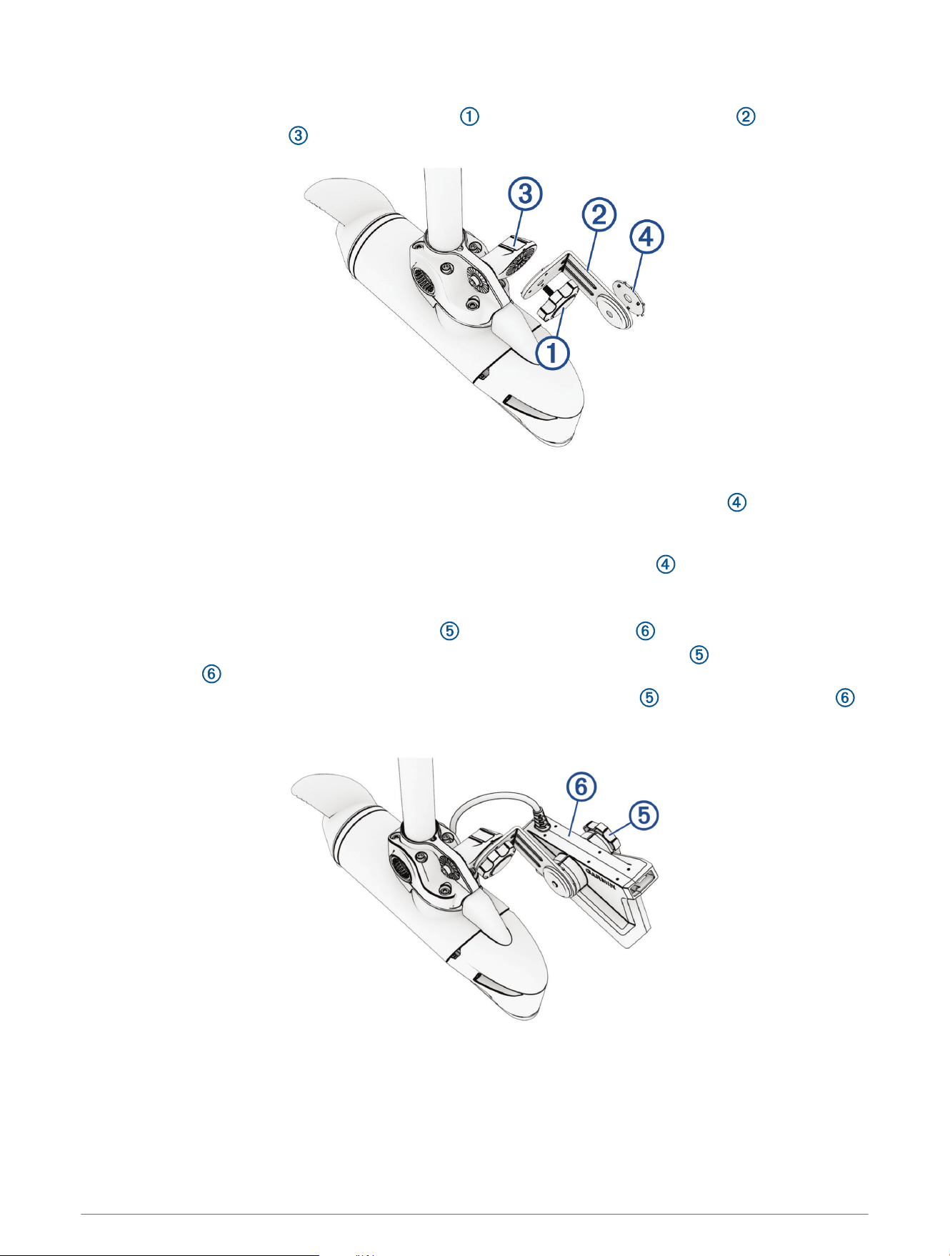
Removing the Propeller Drive Motor
NOTE: Removing and reinstalling the motor is much easier with a second person or an adjustable stand to
support the motor.
1 Using a 5mm hex bit or wrench, remove the six screws that secure the shaft base to the propeller drive
motor.
You should dispose of these six screws. New screws, washers, and O-rings are provided in the kit.
2 If your trolling motor has a transducer installed, using the tool included in the kit, remove the recessed nut
that secures the transducer cable to the shaft.
5
3 Straighten the cables at the top of the shaft, and slowly pull the propeller drive motor away from the shaft
base until you can see the power and data cables connected to the propeller drive motor.
4 Holding the cables only, slowly pull them through the shaft, taking care that the connectors do not get caught
on the top of the shaft.
NOTICE
When removing the propeller drive motor from the shaft, you must pull the cables themselves, and not the
motor. Pulling on the propeller drive motor may damage the cable connections inside the motor. The motor
should not be supported by the cables alone. Supporting the motor only with the cables may damage the motor.
The power cables and transducer cable (if present) should pull through the shaft completely.
Removing the Cable Grommets
1 Using the tool included in the kit, remove the recessed grommet nuts from both sides.
2 Push out the grommets from the inside of the downshaft adapter.
6
Replacing the Motor Gaskets
Before you can replace the motor gaskets, you must remove the propellor drive motor and pull all cables
completely through the shaft.
1 Remove and discard the blue motor gasket and black motor gasket .
2 Using the grease packet included in the kit, apply grease to the new blue and black motor gaskets included in
the kit and install them in place of the gaskets you removed.
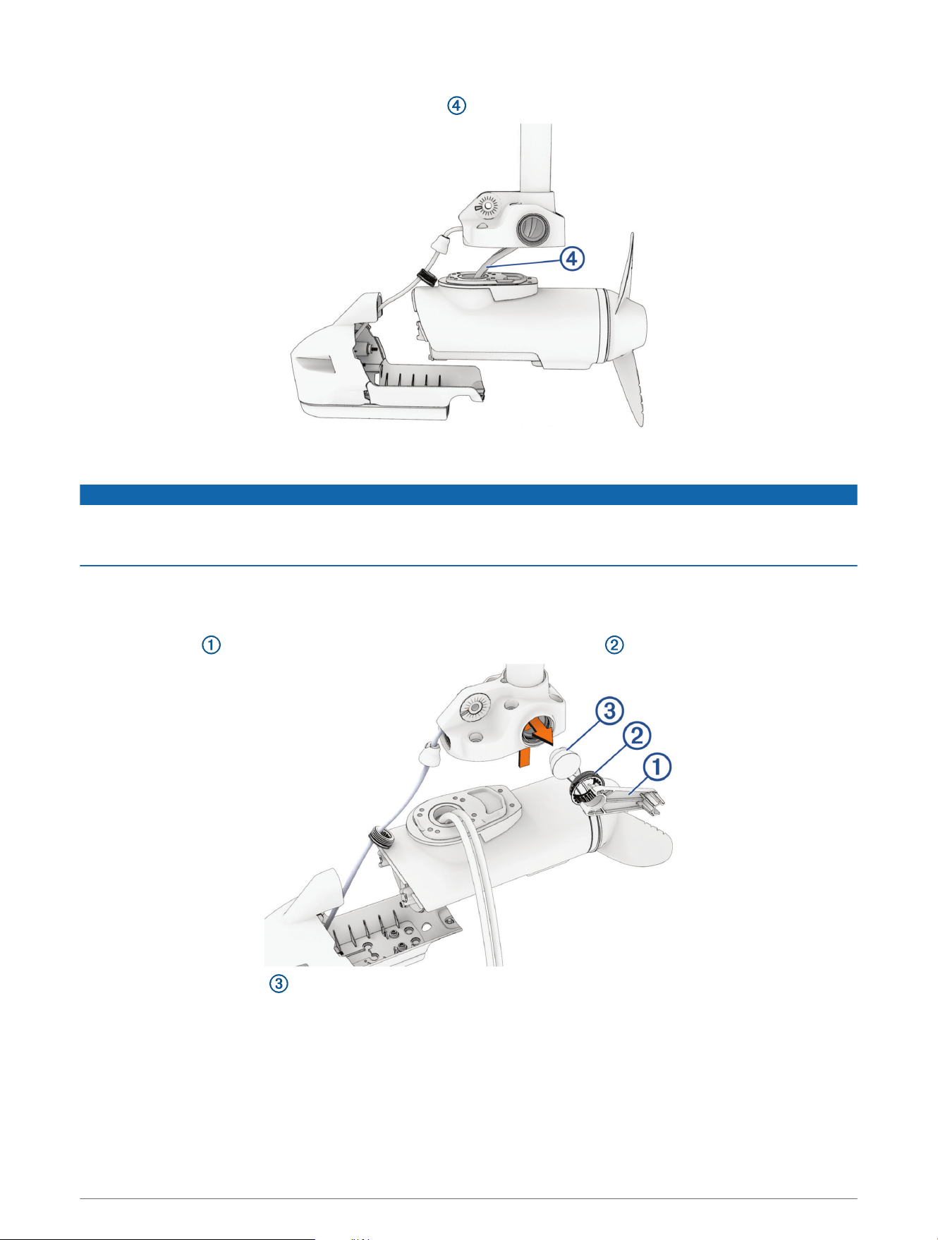
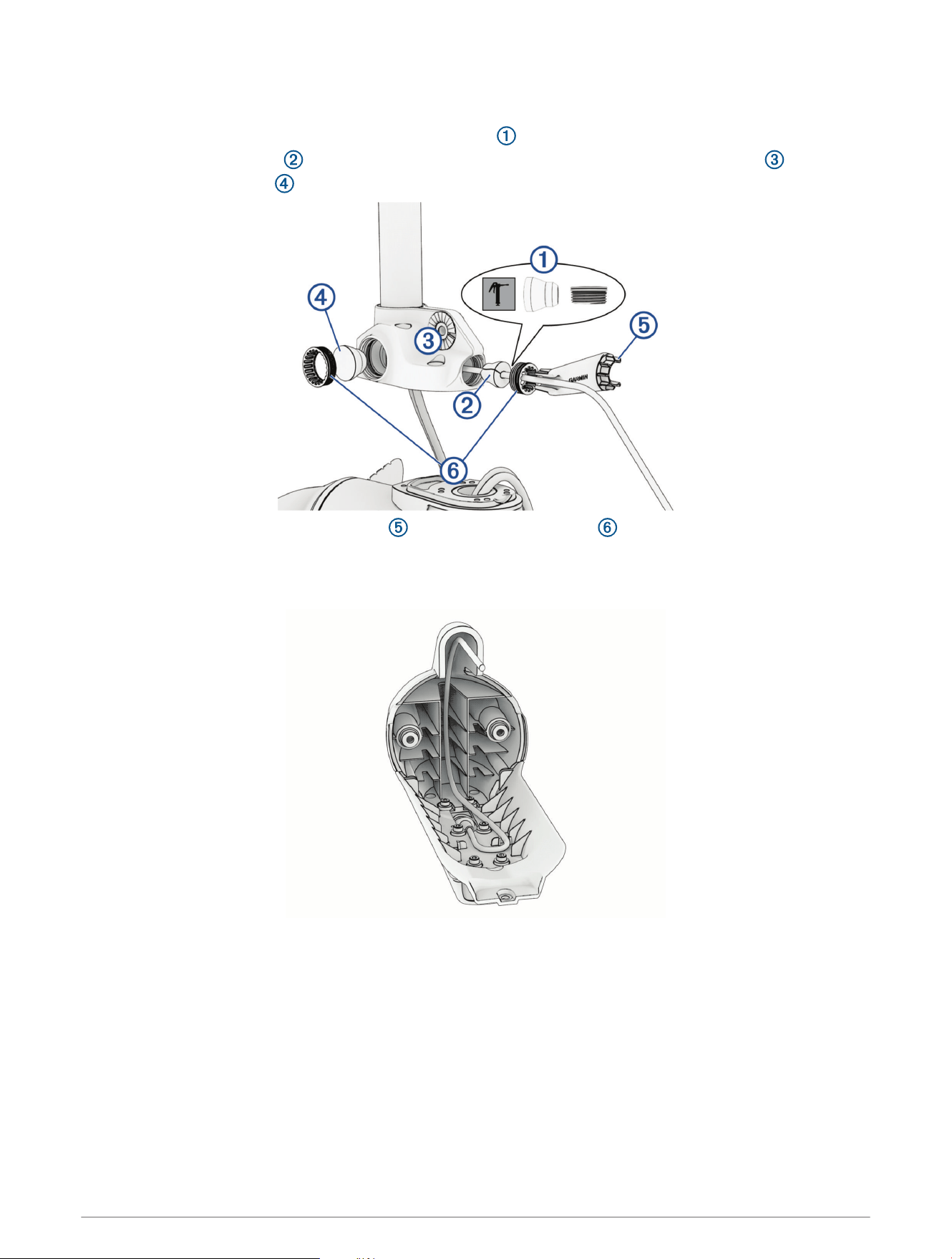
Feeding the Cables Through the Shaft
NOTE: It is strongly suggested to have a second person or a support hold the motor while feeding the cables
through the shaft to ease installation.
1 Using diagonal pliers, carefully cut off the locking ring from the connector at the end of the LiveScope
transducer cable.
2 Place the grommet nut over the LiveScope cable with the threaded side facing the downshaft adapter.
3 Feed the LiveScope cable a few feet into the shaft through the side hole of the downshaft adapter.
4 Using electrical tape, bundle the power cables and any existing transducer cable in a triangular pattern
with the transducer cable leading about 7.5 cm (3 in.). Bundle the cables every 15 cm (6 in.).
NOTE: You should only bundle the existing power and transducer cables, and should not include the
LiveScope cable in the bundle.
7
5 Feed the LiveScope cable completely through the shaft.
NOTE: You should leave approximately 15 to 20 cm (6 to 8in.) of LiveScope cable between the downshaft
adapter and transducer to allow for repositioning and changing modes after installation.
6 Feed the bundled cables completely through the shaft.
TIP: If there is too much resistance while running the cables, back the cables out 2.5 cm (1 in.) and try again.
7 Remove any accessible electrical tape after running the cables through.
Installing the LiveScope Cable Grommet
1 Apply a thin film of the included marine grease to the LiveScope cable grommet and along the section of
the LiveScope cable that feeds through the grommet.
2 Place the grommet over the LiveScope cable and slide it into the downshaft adapter .
3 Using the included grommet nut wrench, tighten the grommet nut .
8
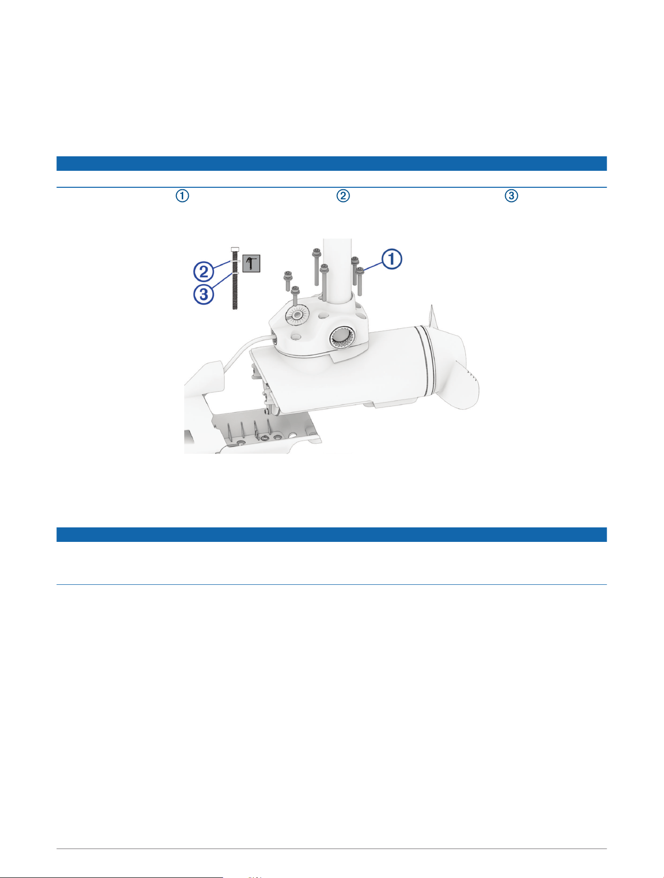
Installing the Propeller Drive Motor
Before you can install the propeller drive motor in the shaft, you must route the LiveScope transducer cable
through the shaft (Feeding the Cables Through the Shaft, page7).
1 Using canned compressed air or an air compressor, blow out any dirt or debris in the six threaded holes on
the top of the propeller drive motor.
2 Gently pull the ends of the power cables as you feed them the rest of the way through the shaft.
NOTICE
When feeding the cables, you must pull on the cable and not on the cable connectors.
3 Prepare the six bolts in the kit by placing a washer and a 4.75mm (
3
/
16
in.) O-ring on each one.
NOTE: There are three different bolt lengths. Make sure the bolts are in the positions shown in the illustration
before tightening.
4 Using the grease packet included in the kit, apply grease to the 4.75mm (
3
/
16
in.) O-ring on each bolt.
Avoid getting grease on the bolt threads.
5 Apply a medium-strength thread-locking compound (not included) such as LOCTITE
®
243
™
to the threads in
the six threaded holes on the top of the propeller drive motor.
NOTICE
You must apply thread-locking compound in these holes to maintain a tight connection between the shaft base
and the propeller drive motor. Failure to use thread-locking compound can lead to water ingress and damage to
the motor.
6 Using a 5mm hex bit or wrench, thread all six of the prepared bolts approximately halfway to make sure that
the shaft base and the propeller drive motor are properly aligned and the gasket is in place.
7 With the shaft base and the propeller drive motor properly aligned, lightly tighten all six bolts by hand.
8 Using a torque wrench, tighten all six bolts to 4N-m (35lbf-in).
9
Installing the Grommets
1 Using the grease packet included in the kit, apply a thin film of grease to the grommets and the section of the
transducer cable that feeds through the cable grommet .
2 Place the cable grommet over the transducer cable and slide it into the downshaft adapter .
3 Slide the solid grommet into the downshaft adapter.
4 Using the included grommet nut wrench , tighten the grommet nuts .
Installing the Nose Cone and Skeg
1 Route the transducer cable through the nose cone so it will fit correctly onto the propeller drive motor.
2 Place the nose cone onto the propeller drive motor.
10
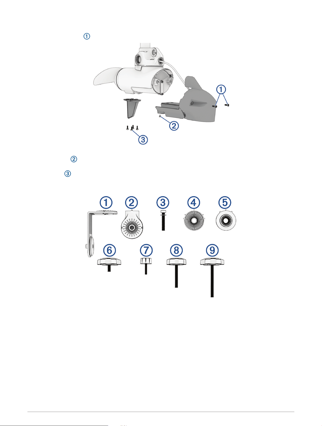
3 Using a 4mm hex bit or wrench, secure the front of the nose cone to the propeller drive motor using the
existing two screws .
4 Using a 3mm hex bit or wrench, secure the bottom of the nose cone to the propeller drive motor using the
existing screw .
5 Using a 4mm hex bit or wrench, secure the skeg to the bottom of the propeller drive motor using the existing
four screws .
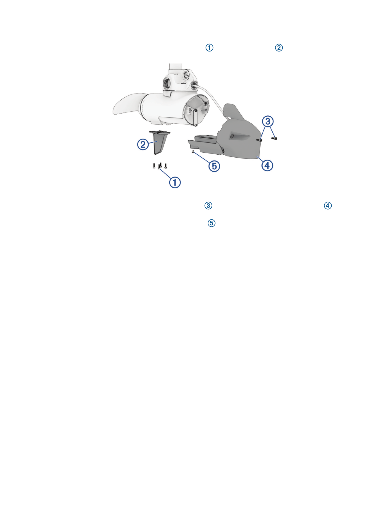
Adapter Kit Overview
11
Item Name Description
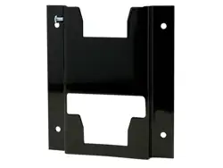
Transducer bracket
Holds the LVS32, LVS34, or LVS62 transducer (sold separately) on the
trolling motor
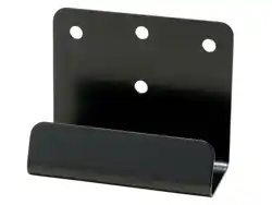
Mounting puck Provides a mounting location for the transducer bracket.
M8 socket head cap screw
and washer
Secures the mounting puck to the motor
LVS34/LVS62 adapter disc Smaller disc profile with wider ridged section
LVS32 adapter disc Thicker disc profile with narrow ridged section
Bracket attachment knob
Large knob with short threaded section that secures the transducer
bracket to the mounting puck
LVS32 attachment knob
Small knob with short threaded section that secures an LVS32 trans
ducer to the transducer bracket
LVS34 attachment knob
Medium knob with medium threaded section that secures an LVS34
transducer to the transducer bracket
LVS 62 attachment knob
Large knob with long threaded section that secures an LVS62 trans
ducer to the transducer bracket
Attaching the LiveScope Mounting Puck
1 Align the prominent tooth on the mounting puck with the recess on the downshaft adapter .
2 Fasten the mounting puck to the downshaft adapter using the included hex head screw and washer .
3 Using a torque wrench, tighten the hex head screw to 7 N-m (62 lbf-in).
12
Assembling the LiveScope Mounting Bracket and Transducer
1 Using the large knob with a short threaded section , attach the short side of the bracket to the
LiveScope mounting puck .
2 Select an action:
• For LVS34 and LVS62 transducers, peel the backing off of the smaller transducer disc , align the pins
with the pinholes on the mounting bracket, and press the sticky side on the outside of the mounting
bracket.
• For an LVS32 transducer, peel the backing off of the thicker transducer disc , align the pins with the
pinholes on the mounting bracket, and press the sticky side on the outside of the mounting bracket.
3 Select an action:
• For an LVS32 transducer, use the small knob to attach the transducer to the bracket.
• For an LVS34 transducer, use the medium knob with a medium threaded section to attach the
transducer to the bracket.
• For an LVS62 transducer, use the large knob with a long threaded section to attach the transducer
to the bracket.
13
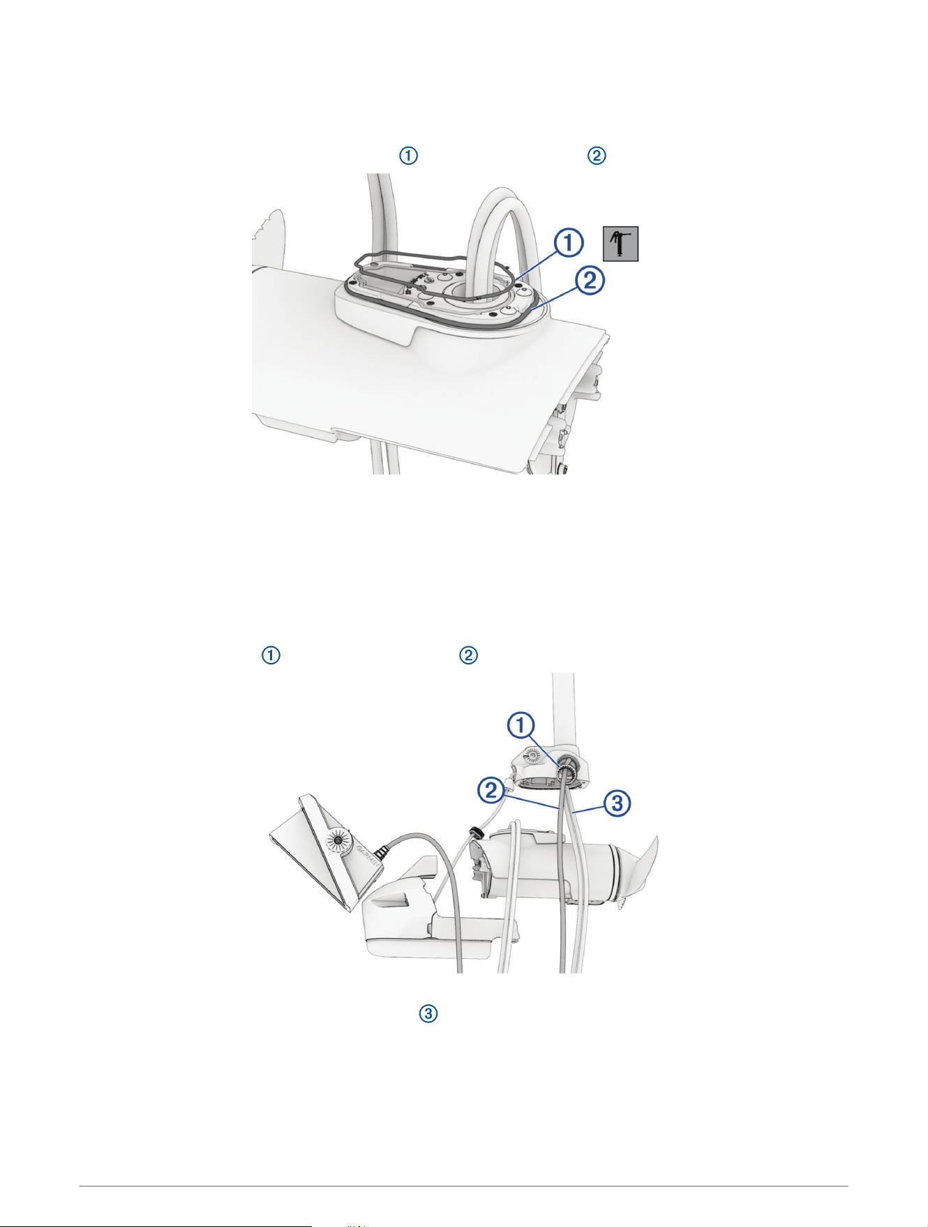
Routing the LiveScope Cable through the Shaft Cap
1 Feed the LiveScope cable completely through the square hole in the shaft cap.
2 Install the grommet on the LiveScope cable.
The grommet is split on one side to make it easy to install on the cable.
3 Push from the outside to secure the square grommet in the shaft cap.
4 Route the LiveScope cable alongside the coil cable to the GLS
™
10, using electrical tape to hold the cables
together.
5 Route the LiveScope cable to the GLS10 and connect it.
Connecting the Cables in the Shaft Cap
1 Place the protective coverings on the power cables .
2 Reconnect the power cables and, using a 2.5 mm hex bit or wrench, tighten the set screws .
3 Slide the protective coverings over the power cable connections.
4 Secure the power cables to the shaft cap using zip ties at the locations you removed them when
disconnecting the power wires .
5 Install the included split collar on the LiveScope transducer cable (Installing Locking Rings on the Cables,
page15).
6 If present, install the included split collar on the GT56 transducer cable.
7 Reconnect the USB and transducer cable (if present), and tighten the collars.
8 Align both sections of the data cable connector and press together to connect them.
14
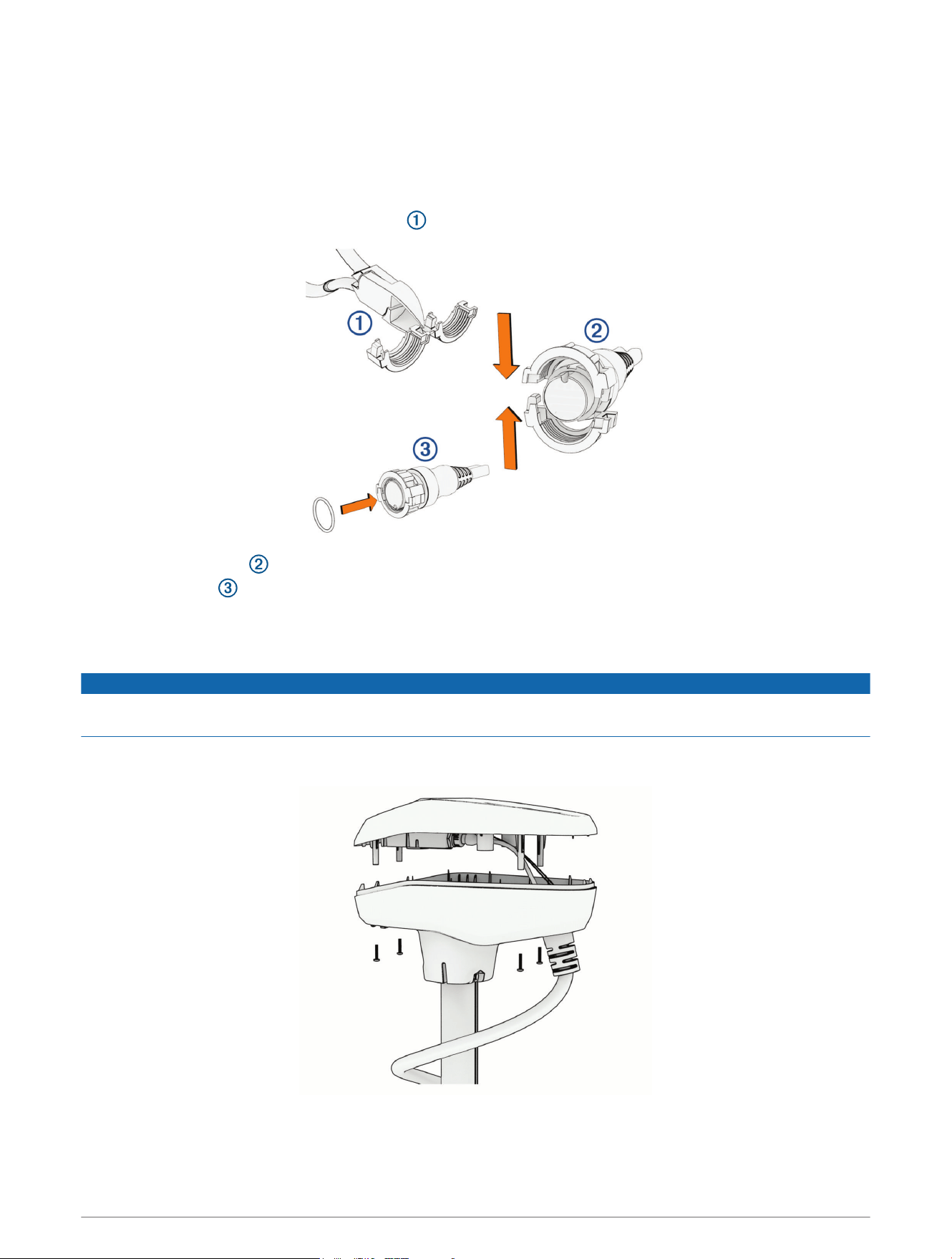
Installing Locking Rings on the Cables
Before you install locking rings on the cables, you must route the cables through the shaft and into the shaft
cap.
To make the cable-routing process possible, you removed the locking rings from the transducer cables
previously during the LiveScope transducer bracket installation process. Replacement locking rings are provided
for the LiveScope transducer cable and the GT56 transducer cable (if equipped).
1 Separate the two halves of the locking ring .
2 Align the two halves of the locking ring over the cable and snap them together.
3 Insert the o-ring into the end of the connector.
Closing the Shaft Cap
1 Place the lid on the shaft cap.
NOTICE
Ensure the cables are routed away from pinch points before securing the shaft cap lid to avoid damaging the
cables.
2 Using a #2 Phillips bit or screwdriver, install the four screws you removed previously to secure the lid of the
shaft cap.
© 2022 Garmin Ltd. or its subsidiaries
Garmin
®
, the Garmin logo, Force
®
, and LiveScope
™
are trademarks of Garmin Ltd. or its subsidiaries, registered in the USA and other countries. These trademarks may not
be used without the express permission of Garmin.
LOCTITE
®
is a trademark of Henkel Corporation in the U.S. and elsewhere.
15

© 2022 Garmin Ltd. or its subsidiaries
support.garmin.com