Quick Start Guide
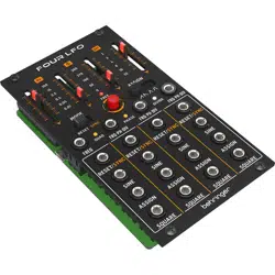
FOUR LFO
Quad LFO with Assignable Waveforms for Eurorack
V 2.0
2 3Quick Start Guide
FOUR LFO
9. No colocar cerca de
fuentes de llama desnuda,
como velas encendidas.
10. Rango de temperatura
de funcionamiento de 5° a
45°C (41° a 113° F).
NEGACIÓN LEGAL
Music Tribe no admite ningún
tipo de responsabilidad por
cualquier daño o pérdida
que pudiera sufrir cualquier
persona por conar total
o parcialmente en la
descripciones, fotografías
o armaciones contenidas
en este documento.
Las especicaciones
técnicas, imágenes y otras
informaciones contenidas
en este documento están
sujetas a modicaciones sin
previo aviso. Todas las marcas
comerciales que aparecen
aquí son propiedad de sus
respectivos dueños. Midas,
Klark Teknik, Lab Gruppen,
Lake, Tannoy, Turbosound,
TC Electronic, TC Helicon,
Behringer, Bugera, Aston
Microphones y Coolaudio son
marcas comerciales o marcas
registradas de Music Tribe
Global Brands Ltd. © Music
Tribe Global Brands Ltd.
2024 Reservados todos los
derechos.
GARANTÍA LIMITADA
Si quiere conocer los detalles
y condiciones aplicables
de la garantía así como
información adicional sobre
la Garantía limitada de Music
Tribe, consulte online toda
la información en la web
community.musictribe.
com/support.
(FR)
Consignes de
sécurité
1. Veuillez lire et suivre
toutes les instructions.
2. Gardez l'appareil
éloigné de l'eau, sauf pour
les produits destinés à une
utilisation en extérieur.
3. Nettoyez uniquement
avec un chion sec.
4. Ne bloquez aucune
ouverture de ventilation.
Installez conformément aux
instructions du fabricant.
5. N'installez pas près de
sources de chaleur telles
que radiateurs, grilles de
chaleur, cuisinières ou
autres appareils (y compris
les amplicateurs) qui
produisent de la chaleur.
6. Utilisez uniquement
les accessoires spéciés par
le fabricant.
7. Utilisez
uniquement
des chariots,
des supports,
des trépieds, des supports ou
des tables spéciés. Faites
attention pour éviter le
renversement lors du
déplacement de la
combinaison chariot/
appareil.
8.
Évitez l'installation dans
des espaces connés comme
les bibliothèques.
9. Ne pas placer près de
sources de amme nue, telles
que des bougies allumées.
10.
Plage de température de
fonctionnement de 5° à 45°C
(41° à 113)
DÉNI LÉGAL
Music Tribe ne peut être
tenu pour responsable pour
toute perte pouvant être
subie par toute personne
se ant en partie ou en
totalité à toute description,
photographie ou armation
contenue dans ce document.
Les caractéristiques,
l’apparence et d’autres
informations peuvent faire
l’objet de modications
sans notication. Toutes les
marques appartiennent à
(EN)
Safety Instruction
1. Please read and follow
all instructions.
2. Keep the apparatus
away from water, except for
outdoor products.
3. Clean only with a
dry cloth.
4. Do not block any
ventilation openings. Install
in accordance with the
manufacturer’s instructions.
5. Do not install near
any heat sources such as
radiators, heat registers,
stoves or other apparatus
(including ampliers) that
produce heat.
6. Use only attachments/
accessories specied by the
manufacturer.
7. Use only
specied carts,
stands, tripods,
brackets, or
tables. Use caution to prevent
tip-over when moving the
cart/apparatus combination.
8. Avoid installing
in conned spaces like
bookcases.
9. Do not place near
naked ame sources, such as
lighted candles.
10. Operating temperature
range 5° to 45°C (41° to
113°F).
LEGAL DISCLAIMER
Music Tribe accepts no liability
for any loss which may be
suered by any person who
relies either wholly or in
part upon any description,
photograph, or statement
contained herein. Technical
specications, appearances
and other information are
subject to change without
notice. All trademarks are the
property of their respective
owners. Midas, Klark Teknik,
Lab Gruppen, Lake, Tannoy,
Turbosound, TC Electronic,
TC Helicon, Behringer, Bugera,
Aston Microphones and
Coolaudio are trademarks
or registered trademarks of
Music Tribe Global Brands Ltd.
© Music Tribe Global Brands
Ltd. 2024 All rights reserved.
LIMITED WARRANTY
For the applicable warranty
terms and conditions and
additional information
regarding Music Tribe’s
Limited Warranty, please
see complete details online
at community.musictribe.
com/support.
(ES)
Instrucción de
seguridad
1. Por favor, lea y siga
todas las instrucciones.
2. Mantenga el aparato
alejado del agua, excepto
para productos destinados al
uso en exteriores.
3. Limpie solo con un
paño seco.
4. No bloquee ninguna
abertura de ventilación.
Instale de acuerdo con las
instrucciones del fabricante.
5. No instale cerca de
fuentes de calor como
radiadores, registros de calor,
estufas u otros aparatos
(incluyendo amplicadores)
que generen calor.
6. Utilice solo accesorios
especicados por el
fabricante.
7. Use solo
carros,
soportes,
trípodes,
soportes o mesas
especicados. Tenga
precaución para evitar el
vuelco al mover la
combinación carro/aparato.
8. Evite la instalación en
espacios connados como
estanterías.
4 5Quick Start Guide
FOUR LFO
(PT)
Instruções
de Seguranç
Importantes
1. Por favor, leia e siga
todas as instruções.
2. Mantenha o aparelho
longe da água, exceto para
produtos destinados ao
uso externo.
3. Limpe apenas com um
pano seco.
4. Não bloqueie nenhuma
abertura de ventilação.
Instale de acordo com as
instruções do fabricante.
5. Não instale próximo
a fontes de calor, como
radiadores, grelhas de calor,
fogões ou outros aparelhos
(incluindo amplicadores)
que gerem calor.
6. Use apenas acessórios
especicados pelo fabricante.
7. Use
apenas
carrinhos,
suportes,
tripés, suportes ou mesas
especicados. Tenha cuidado
para evitar tombamentos ao
mover a combinação
carrinho/aparelho.
8. Evite instalar em espaços
connados, como estantes.
9. Não coloque perto de
fontes de chama nua, como
velas acesas.
10. Intervalo de
temperatura de operação de
5° a 45°C (41° a 113° F).
LEGAL RENUNCIANTE
O Music Tribe não se
responsabiliza por perda
alguma que possa ser sofrida
por qualquer pessoa que
dependa, seja de maneira
completa ou parcial, de
qualquer descrição, fotograa,
ou declaração aqui contidas.
Dados técnicos, aparências
e outras informações estão
sujeitas a modicações sem
aviso prévio. Todas as marcas
são propriedade de seus
respectivos donos. Midas,
Klark Teknik, Lab Gruppen,
Lake, Tannoy, Turbosound,
TC Electronic, TC Helicon,
Behringer, Bugera, Aston
Microphones e Coolaudio são
marcas ou marcas registradas
do Music Tribe Global Brands
Ltd. © Music Tribe Global
Brands Ltd. 2024 Todos
direitos reservados.
GARANTIA LIMITADA
Para obter os termos
de garantia aplicáveis e
condições e informações
adicionais a respeito da
garantia limitada do Music
Tribe, favor vericar detalhes
na íntegra através do website
community.musictribe.
com/support.
(IT)
Istruzioni di
sicurezza importanti
1. Per favore, leggere e
seguire tutte le istruzioni.
2.
Mantenere l'apparecchio
lontano dall'acqua, tranne
per i prodotti destinati all'uso
all'aperto.
3. Pulire solo con un
panno asciutto.
4. Non ostruire alcuna
apertura di ventilazione.
Installare in conformità alle
istruzioni del produttore.
5. Non installare vicino
a fonti di calore come
termosifoni, bocchette
di calore, fornelli o altri
apparecchi (compresi
gli amplicatori) che
producono calore.
6. Utilizzare solo accessori
specicati dal produttore.
7.
Usare solo
carrelli,
supporti,
treppiedi, stae
o tavoli specicati. Prestare
attenzione per evitare il
ribaltamento durante lo
spostamento della
leurs propriétaires respectifs.
Midas, Klark Teknik, Lab
Gruppen, Lake, Tannoy,
Turbosound, TC Electronic,
TC Helicon, Behringer,
Bugera, Aston Microphones et
Coolaudio sont des marques
ou marques déposées de
Music Tribe Global Brands Ltd.
© Music Tribe Global Brands
Ltd. 2024 Tous droits réservés.
GARANTIE LIMITÉE
Pour connaître les
termes et conditions de
garantie applicables,
ainsi que les informations
supplémentaires et détaillées
sur la Garantie Limitée de
Music Tribe, consultez le
site Internet community.
musictribe.com/support.
(DE)
Wichtige
Sicherheitshinweise
1. Bitte lesen Sie alle
Anweisungen sorgfältig
durch und befolgen Sie diese.
2. Halten Sie das Gerät
von Wasser fern, außer
für Produkte, die für den
Außeneinsatz vorgesehen
sind.
3. Reinigen Sie es nur mit
einem trockenen Tuch.
4. Blockieren Sie keine
Belüftungsönungen.
Installieren Sie gemäß den
Anweisungen des Herstellers.
5. Installieren Sie
nicht in der Nähe von
Wärmequellen wie
Heizkörpern, Heizregistern,
Öfen oder anderen Geräten
(einschließlich Verstärkern),
die Wärme erzeugen.
6. Verwenden Sie nur
Zubehörteile, die vom
Hersteller angegeben sind.
7. Verwenden
Sie nur
spezizierte
Wagen,
Ständer, Stative, Halterungen
oder Tische. Achten Sie
darauf, beim Bewegen der
Wagen-Geräte-Kombination
ein Umkippen zu vermeiden.
8. Vermeiden Sie die
Installation in beengten
Räumen wie Bücherregalen.
9. Nicht in der Nähe von
oenen Flammenquellen
platzieren, wie
brennende Kerzen.
10. Betriebstem-
peraturbereich von 5° bis
45°C (41° bis 113°F).
HAFTUNGSAUSSCHLUSS
Music Tribe übernimmt
keine Haftung für Verluste,
die Personen entstanden
sind, die sich ganz oder
teilweise auf hier enthaltene
Beschreibungen, Fotos
oder Aussagen verlassen
haben. Technische Daten,
Erscheinungsbild und andere
Informationen können ohne
vorherige Ankündigung
geändert werden. Alle
Warenzeichen sind Eigentum
der jeweiligen Inhaber. Midas,
Klark Teknik, Lab Gruppen,
Lake, Tannoy, Turbosound,
TC Electronic, TC Helicon,
Behringer, Bugera, Aston
Microphones und Coolaudio
sind Warenzeichen oder
eingetragene Warenzeichen
der Music Tribe Global
Brands Ltd. © Music Tribe
Global Brands Ltd. 2024 Alle
Rechte vorbehalten.
BESCHRÄNKTE GARANTIE
Die geltenden
Garantiebedingungen und
zusätzliche Informationen
bezüglich der von Music Tribe
gewährten beschränkten
Garantie nden Sie online
unter community.musictribe.
com/support.
6 7Quick Start Guide
FOUR LFO
Midas, Klark Teknik, Lab
Gruppen, Lake, Tannoy,
Turbosound, TC Electronic, TC
Helicon, Behringer, Bugera,
Aston Microphones en
Coolaudio zijn handelsmerken
of gedeponeerde
handelsmerken van Music
Tribe Global Brands Ltd.
© Music Tribe Global Brands
Ltd. 2024 Alle rechten
voorbehouden.
BEPERKTE GARANTIE
Voor de toepasselijke
garantievoorwaarden en
aanvullende informatie met
betrekking tot de beperkte
garantie van Music Tribe, zie
de volledige details online
op community.musictribe.
com/support.
(SE)
Viktiga
säkerhetsanvisningar
1. Vänligen läs och följ alla
instruktioner noggrant.
2. Håll apparaten borta
från vatten, förutom för
utomhusprodukter.
3. Rengör endast med en
torr trasa.
4. Blockera inte några
ventilationsöppningar.
Installera enligt tillverkarens
anvisningar.
5. Installera inte nära
några värmekällor som
element, värmeregistrar,
spisar eller andra apparater
(inklusive förstärkare) som
genererar värme.
6. Använd endast tillbehör
som anges av tillverkaren.
7. Använd
endast
specicerade
vagnar, ställ,
stativ, fästen eller bord. Var
försiktig för att undvika att
vagnen/
apparatkombinationen
tippar när den yttas.
8. Undvik installation i trånga
utrymmen som bokhyllor.
9. Placera inte nära öppen
låga, såsom tända ljus.
10. Driftstem-
peraturområde 5° till 45°C
(41° till 113°F).
FRISKRIVNINGSKLAUSUL
Music Tribe tar inget ansvar
för någon förlust som kan
drabbas av någon person som
helt eller delvis förlitar sig på
någon beskrivning, fotogra
eller uttalande som nns
här. Tekniska specikationer,
utseenden och annan
information kan ändras utan
föregående meddelande. Alla
varumärken tillhör respektive
ägare. Midas, Klark Teknik,
Lab Gruppen, Lake, Tannoy,
Turbosound, TC Electronic,
TC Helicon, Behringer, Bugera,
Aston Microphones och
Coolaudio är varumärken
eller registrerade varumärken
som tillhör Music Tribe Global
Brands Ltd. © Music Tribe
Global Brands Ltd. 2024 Alla
Rättigheter reserverade.
BEGRÄNSAD GARANTI
För tillämpliga garantivillkor
och ytterligare information
om Music Tribes begränsade
garanti, se fullständig
information online på
community.musictribe.
com/support.
(PL)
Ważne informacje
o bezpieczeństwie
1.
Proszę przeczytać i ścisłe
przestrzegać wszystkich
instrukcji.
2. Trzymaj urządzenie z
dala od wody, z wyjątkiem
produktów przeznaczonych
do użytku na zewnątrz.
3. Czyść tylko suchą
szmatką.
4. Nie blokuj żadnych
otworów wentylacyjnych.
Instaluj zgodnie z
instrukcjami producenta.
combinazione carrello/
apparecchio.
8. Evitare l'installazione in
spazi connati come librerie.
9. Non posizionare vicino
a fonti di amma nude,
come candele accese.
10. Intervallo di
temperatura di
funzionamento da 5° a 45°C
(41° a 113°F)
DISCLAIMER LEGALE
Music Tribe non si assume
alcuna responsabilità per
eventuali danni che possono
essere subiti da chiunque
si adi in tutto o in parte
a qualsiasi descrizione,
fotograa o dichiarazione
contenuta qui. Speciche
tecniche, aspetti e altre
informazioni sono soggette
a modiche senza preavviso.
Tutti i marchi sono di proprietà
dei rispettivi titolari. Midas,
Klark Teknik, Lab Gruppen,
Lake, Tannoy, Turbosound,
TC Electronic, TC Helicon,
Behringer, Bugera, Aston
Microphones e Coolaudio sono
marchi o marchi registrati
di Music Tribe Global Brands
Ltd. © Music Tribe Global
Brands Ltd. 2024 Tutti i
diritti riservati .
GARANZIA LIMITATA
Per i termini e le condizioni
di garanzia applicabili e le
informazioni aggiuntive
relative alla garanzia limitata
di Music Tribe, consultare
online i dettagli completi
su community.musictribe.
com/support.
(NL)
Belangrijke
veiligheidsvoorschriften
1. Lees alsjeblieft alle
instructies en volg deze op.
2. Houd het apparaat uit
de buurt van water, behalve
voor producten die bedoeld
zijn voor buitengebruik.
3. Reinig alleen met een
droge doek.
4. Blokker geen
ventilatieopeningen.
Installeer volgens de
instructies van de fabrikant.
5. Installeer niet in de
buurt van warmtebronnen
zoals radiatoren, warmte
registers, fornuizen of
andere apparaten (inclusief
versterkers) die warmte
produceren.
6. Gebruik alleen
accessoires die door de
fabrikant zijn gespeciceerd.
7. Gebruik
alleen
gespeciceerde
karren,
standaards, statieven,
beugels of tafels. Wees
voorzichtig om kantelen te
voorkomen bij het
verplaatsen van de kar/
apparaatcombinatie.
8. Vermijd installatie in
afgesloten ruimtes zoals
boekenkasten.
9. Plaats niet in de buurt
van naakte vlambronnen,
zoals brandende kaarsen.
10. Bedrijfstem-
peratuurbereik van 5° tot
45°C (41° tot 113°F).
WETTELIJKE ONTKENNING
Music Tribe aanvaardt
geen aansprakelijkheid
voor enig verlies dat kan
worden geleden door
een persoon die geheel
of gedeeltelijk vertrouwt
op enige beschrijving,
foto of verklaring hierin.
Technische specicaties,
verschijningen en andere
informatie kunnen zonder
voorafgaande kennisgeving
worden gewijzigd. Alle
handelsmerken zijn
eigendom van hun
respectievelijke eigenaren.
8 9Quick Start Guide
FOUR LFO
9. 裸火のような火の
元の近くに置 かないで
ください。
10. 動作温度範囲は摂
氏 5 度から 45 度 (華氏
41 度から 113 度) です。
法的放棄
ここに含まれる記述、写
真、 意見の全体または一
部に依拠して、いかなる
人が損害を生じさせた
場合にも、
Music Tribe は一
切の賠償責任を負いま
せん。技術仕様、外観お
よびその他の情報は予
告なく変更になる場合
があります。商標はす
べて、それぞれの所有者
に帰属します。Midas、Klark
Teknik
、 Lab Gruppen、Lake、
Tannoy
、 Turbosound、 TC
Electronic
、 TC Helicon、
Behringer
、Bugera、Aston
Microphones
および Coolaudio
は Music Tribe Global Brands
Ltd.
の商標または‑登録
商標です。 © Music Tribe
Global Brands Ltd. 2024
無断
転用禁止。
限定保証
適用される保証条件と
Music Tribe
の限定保証に
関する概要については、
オンライン上 community.
musictribe.com/support
にて詳細をご確認くだ
さい。
(CN) 安全须知
1.
请阅读, 保存, 遵守
所有的说明, 注意所有
的警示。
2. 请勿在靠近水的地方
使用本产品。
3. 请用干布清洁本
产品。
4. 请只使用厂家指定的
附属设备和配件。 不要堵
塞任何通风口。按照制造商
的说明进行安装。
5. 请只使用
厂家指定的或
随货销售的手
推车, 架子, 三
角架, 支架和桌子等。 若使
用手推车来搬运设备, 请
注意安全放置设备, 以避
免手推车和设备倾倒而
受伤。
6. 请勿安装在密闭空间,
如书柜或类似装置。
7. 请勿将本产品安装在
热源附近, 如暖气片, 炉子
或其它产生热量的设备
(包括功放器)。 产品上不
要放置裸露的火焰源, 如
点燃的蜡烛。
8.
如果液体流入或异物
落入设备内, 设备遭雨淋
或受潮, 设备不 能正常运
作或被摔坏等, 设备受损
需进行维修时, 所有维修
均须由 合格的维修人员
进行维修。
法律声明
对于任何因在此说明书
提到的全部或部份描述、
图片或声明而造成的损
失,
Music Tribe 不负任何责
任。 技术参数和外观若有
更改, 恕不另行通知。 所有
的商标均为其各自所有者
的财产。 Midas, Klark Teknik,
Lab Gruppen, Lake, Tannoy,
Turbosound, TC Electronic,
TC Helicon, Behringer,
Bugera, Aston Microphones
和 Coolaudio 是 Music Tribe
Global Brands Ltd.
公司的商
标或注册商标。 © Music
Tribe Global Brands Ltd. 2024
版权所有。
保修条款
有关音乐集团保修的适用
条款及其它相关信息, 请
登陆
community.musictribe.
com/support
网站查看完整
的详细信息。
5. Nie instaluj w pobliżu
źródeł ciepła, takich jak
grzejniki, rejestratory ciepła,
kuchenki lub inne urządzenia
(w tym wzmacniacze), które
generują ciepło.
6. Używaj tylko akcesoriów
określonych przez
producenta.
7. Używaj
tylko
określonych
wózków,
stojaków, statywów,
uchwytów lub stołów.
Uważaj, aby zapobiec
przewróceniu się wózka/
aparatu podczas
przemieszczania.
8. Unikaj instalacji w
ciasnych miejscach, takich jak
regały na książki.
9. Nie umieszczaj w
pobliżu źródeł otwartego
ognia, takich jak
zapalone świeczki.
10. Zakres temperatury
pracy od 5° do 45°C
(41° do 113°F).
ZASTRZEŻENIA PRAWNE
Music Tribe nie ponosi
odpowiedzialności za
jakiekolwiek straty, które
mogą ponieść osoby, które
polegają w całości lub w
części na jakimkolwiek opisie,
fotograi lub oświadczeniu
zawartym w niniejszym
dokumencie. Specykacje
techniczne, wygląd i inne
informacje mogą ulec
zmianie bez powiadomienia.
Wszystkie znaki towarowe są
własnością ich odpowiednich
właścicieli. Midas, Klark
Teknik, Lab Gruppen, Lake,
Tannoy, Turbosound, TC
Electronic, TC Helicon,
Behringer, Bugera, Aston
Microphones i Coolaudio
są znakami towarowymi
lub zastrzeżonymi znakami
towarowymi rmy Music
Tribe Global Brands Ltd. ©
Music Tribe Global Brands
Ltd. 2024 Wszystkie prawa
zastrzeżone.
OGRANICZONA
GWARANCJA
Aby zapoznać się z
obowiązującymi warunkami
gwarancji i dodatkowymi
informacjami dotyczącymi
ograniczonej gwarancji
Music Tribe, zapoznaj się ze
wszystkimi szczegółami w
trybie online pod adresem
community.musictribe.
com/support.
(JP) 安全指示
1. すべての 指示を読ん
で 、従 っ て く だ さ い 。
2. 屋外 の製品を除き、
機 器を水 か ら遠ざけ てく
ださい。
3. 乾いた布でのみ清掃
してくださ い 。
4. 通気口を塞がないで
く だ さ い 。メ ー カ ー の 指
示に従ってインストールし
てください 。
5. 暖 房 器 、ヒ ー ト レ ジ ス
タ ー 、ス ト ー ブ な ど の 発
熱 機 器( ア ン プ を 含 む )
の近くには 取り付 けな い
でください 。
6. メーカーが 指定した
アタッチメント/アクセ
サリー の み 使 用してく
ださい。
7. 指定され
た カ ー ト 、ス
タ ン ド 、三
脚 、ブ ラ ケ ッ
ト 、ま た は テ ー ブ ル の み
使用してください。カー
ト/機器 の組み合わせを
移 動 す る 際 に は 、転 倒 を
防ぐよう注 意 してく
ださい。
8. 書 棚などの密閉され
た空間には設置しないで
ください。
10 11Quick Start Guide
FOUR LFO
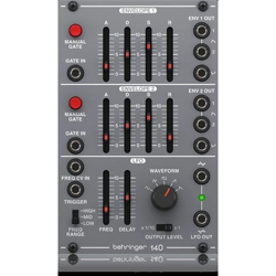
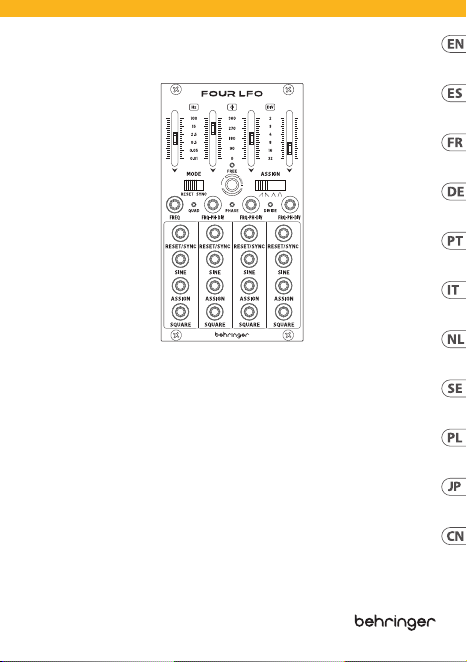
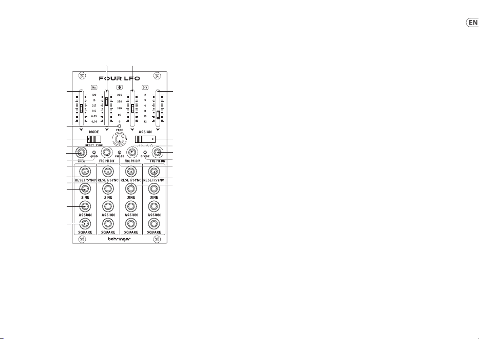
(EN) Controls
(1) FADER 1 – this fader has two
functions: in free-running mode
it sets the frequency for LFO 1;
otherwise it acts as a master
fader for the other three faders to
reference.
(2) FADER 2 – in free-running mode
this acts as frequency control for
LFO 2; otherwise it acts as an oset
against the master for LFO 2.
(3) FADER 3 – as fader 2 but for LFO 3.
(4) FADER 4 – as fader 2 but for LFO 4.
(5) FREE LED – when this LED
is lit the FOUR LFO is in
free-running mode.
(6) MODE – use this switch to
select the action for sockets 16.
In RESET mode a gate applied
to the socket(s) will cause the
waveform(s) of the LFO(s) to reset;
in SYNC mode the LFO(s) will sync
to a clock sent to the socket(s).
(7) TOGGLE – use this button to
switch between:
• Free-running, where the four
LFOs work independently.
• Quad, where LFOs 2 – 4 are
slaved to LFO 1 but are 90°,
180°and 270° out of phase
respectively. Faders 2-4 and
sockets 10-12 control the
amplitude of LFOs 2-4.
• Phase, where faders 2-4 set
the phase of LFOs 2-4 against
LFO 1. Sockets 10-12 allow
further control of shift from
external CVs.
• Divide, where faders 2-4 set
divisions of LFO 1’s frequency
for LFOs 2-4. Sockets 10-12
allow further CV control.
(8) ASSIGN – sets the waveform that
will be output from sockets 18.
Choose between sawtooth, ramp,
triangle and trapezoid. This is a
global setting which will aect all
four LFOs.
(9) FREQ – use this socket to control
the frequency of LFO 1 from an
external CV source, in the range
-5V to +5V.
(10) (11), (12) – FRQ/PH/DIV – use these
sockets to allow external CV control
of LFOs 2-4 according to whichever
mode the FOUR LFO is in. range in
all modes is -5V to +5V.
(13) QUAD LED – this LED is lit when
the FOUR LFO is in Quad mode.
(14) PHASE LED – this LED is lit when
the FOUR LFO is in Phase mode.
FOUR LFO Controls
(4)
(8)
(14
)
(19
)
(18
)
(11
)
(15
)
(12
)
(1)
(7)
(9)
(
16)
(
17)
(
20)
(
21)
(
22)
(2) (3)
(
10)
(
13)
(6)
(5)

12 13Quick Start Guide
FOUR LFO
(21) ASSIGN – assignable waveform
outputs for each LFO, according to
where switch 8 is set.
(22) SQUARE – square wave outputs
for each LFO.
PRECISION
Pressing and holding button 7 puts the
FOUR LFO into precision mode to allow
precise adjustment. The LED for the
current mode will ash, and the faders
will make ne adjustments around the
centre point. When exiting precision
mode the faders will not necessarily
indicate the current setting, so the
relevant LED will continue to ash to
show this.
FIRMWARE UPDATE
On the edge of the circuit board next
to the mode switch (6) there is a micro
USB socket for updating the FOUR
LED’s rmware, using the SynthTribe
application.
HINTS AND TIPS
• Use the output of one LFO
to modulate the selected
parameter of another. Or
cascade your modulation.
• In free-running mode use a
square wave from one LFO to
reset another.
(ES) Controles
(1) FADER 1 – este fader tiene dos
funciones: en el modo autónomo
o “free-running” ajusta la
frecuencia para el LFO 1; en
caso contrario actúa como fader
master de los otros tres faders
para servir como referencia.
(2) FADER 2 – en el modo autónomo
o “free-running” actúa como un
control de frecuencia para LFO 2;
en caso contrario actúa como un
ajuste de desfase con respecto al
master para el LFO 2.
(3) FADER 3 – como el fader 2 pero
para el LFO 3.
(4) FADER 4 – como el fader 2 pero
para el LFO 4.
(5) FREE LED – cuando este piloto
esté encendido, los CUATRO LFO
actuarán en el modo autónomo o
“free-running”.
(6) MODE – use este interruptor para
elegir el funcionamiento de las
tomas 16 a 19. En el modo RESET
un efecto de puerta aplicado a
esas tomas hará que las formas de
onda de los LFO sean reiniciadas;
en el modo SYNC, los LFO se
sincronizarán a una señal de reloj
enviada a esas tomas.
FOUR LFO Controls
(15) DIVIDE LED – this LED is lit when
the FOUR LFO is in Divide mode.
(16) RESET/SYNC 1 – a gate or clock
applied to this socket causes
dierent actions according to mode:
• In SYNC mode it will
synchronize LFO 1 to the
external clock.
• In RESET mode when the LFOs
are free-running it will reset
the waveform cycle of LFO 1.
• In RESET mode when the LFOs
are in QUAD, PHASE or DIVIDE it
will reset the waveform cycles
of all four LFOs.
(17) RESET/SYNC 2 – a gate or clock
applied to this socket causes
dierent actions according to mode:
• In SYNC mode it will
synchronize LFO 2 to the
external clock.
• In RESET mode when the LFOs
are free-running it will reset
the waveform cycle of LFO 2.
• In RESET mode when the LFOs
are in QUAD, PHASE or DIVIDE it
will pause all four LFOs.
(18) RESET/SYNC 3 – a gate or clock
applied to this socket causes
dierent actions according to mode:
• In SYNC mode it will
synchronize LFO 3 to the
external clock.
• In RESET mode when the LFOs
are free-running it will reset
the waveform cycle of LFO 3.
• In RESET mode when the LFOs
are in QUAD, PHASE or DIVIDE it
will reverse all four LFOs.
(19) RESET/SYNC 4 – a gate or clock
applied to this socket causes
dierent actions according
to mode:
• In SYNC mode it will
synchronize LFO 4 to the
external clock.
• In RESET mode when the LFOs
are free-running it will reset
the waveform cycle of LFO 4.
• In RESET mode when the LFOs
are in QUAD, PHASE or DIVIDE
it will shift the assignable
waveform to the next option
on all four LFOs, regardless of
the setting of switch 8. The
waveform selected by switch
8 will be selected again if the
mode is changed.
(20) SINE – sine wave outputs for
each LFO.

14 15Quick Start Guide
FOUR LFO
• En el modo RESET, cuando los
LFO estén en los modos QUAD,
PHASE o DIVIDE, esto reiniciará
el ciclo de las formas de onda
de los cuatro LFO.
(17) RESET/SYNC 2 – una señal
de puerta o reloj aplicada a
esta toma producirá acciones
diferentes de acuerdo al modo:
• En el modo SYNC sincronizará
el LFO 2 a una señal de
reloj externa.
• En el modo RESET, cuando
los LFO estén en el modo
autónomo, reiniciará el ciclo de
la forma de onda del LFO 2.
• En el modo RESET, cuando los
LFO estén en los modos QUAD,
PHASE o DIVIDE, esto dejará en
pausa los cuatro LFO.
(18) RESET/SYNC 3 – una señal
de puerta o reloj aplicada a
esta toma producirá acciones
diferentes de acuerdo al modo:
• En el modo SYNC sincronizará
el LFO 3 a una señal de reloj
externa.
• En el modo RESET, cuando
los LFO estén en el modo
autónomo, reiniciará el ciclo de
la forma de onda del LFO 3.
• En el modo RESET, cuando los
LFO estén en los modos QUAD,
PHASE o DIVIDE, esto invertirá
los cuatro LFO.
(19) RESET/SYNC 4 – una señal
de puerta o reloj aplicada a
esta toma producirá acciones
diferentes de acuerdo al modo:
• En el modo SYNC sincronizará
el LFO 4 a una señal de
reloj externa.
• En el modo RESET, cuando
los LFO estén en el modo
autónomo, reiniciará el ciclo de
la forma de onda del LFO 4.
• En el modo RESET, cuando los
LFO estén en los modos QUAD,
PHASE o DIVIDE, esto cambiará
la forma de onda asignable a la
siguiente opción de los cuatro
LFO, independientemente del
ajuste del interruptor 8. La
forma de onda elegida con el
interruptor 8 será seleccionada
de nuevo si cambia el modo.
(20) SINE – salidas de ondas
sinusoidales para cada LFO.
(21) ASSIGN – salidas de formas de
onda asignables para cada LFO,
de acuerdo a la posición en la que
esté el interruptor 8.
(7) TOGGLE – use este botón para
cambiar entre:
• El modo autónomo o
“free-running”, en el que los
cuatro LFO actuarán de forma
independiente.
• Quad, en el que los LFO 2 – 4
serán esclavos del LFO 1 pero
estarán desfasados en 90°,
180° y 270° respectivamente.
Los faders 2-4 y las tomas 10-12
controlarán la amplitud de los
LFO 2-4.
• Phase, en el que los faders 2-4
ajustarán la fase de los LFO 2-4
con respecto a LFO 1. Las tomas
10-12 permiten un ajuste
mayor de ese cambio desde CV
externos.
• Divide, en el que los faders
2-4 ajustarán las divisiones de
la frecuencia del LFO 1 para
los LFO 2-4. Las tomas 10-12
permiten un mayor control
vía CV.
(8) ASSIGN – este interruptor
ajusta la forma de onda que será
emitida desde las tomas 21. Elija
entre diente de sierra, rampa,
triangular y trapezoidal. Esto es
un ajuste global que afectará a los
cuatro LFO.
(9) FREQ – use esta toma para
controlar la frecuencia del LFO 1
desde una fuente de CV (control
por voltaje) externa, en el rango
de -5 a +5V.
(10) (11), (12) - FRQ/PH/DIV – use estas
tomas para permitir el control
por CV externo de los LFO 2-4
dependiendo del modo en el que
esté el FOUR LFO. El rango en
todos los modos es de -5 a +5V.
(13) QUAD LED – este piloto se
iluminará cuando el FOUR LFO
esté en el modo Quad.
(14) PHASE LED – este piloto se
iluminará cuando el FOUR LFO
esté en el modo Phase.
(15) DIVIDE LED – este piloto se
iluminará cuando el FOUR LFO
esté en el modo Divide.
(16) RESET/SYNC 1 – una señal
de puerta o reloj aplicada a
esta toma producirá acciones
diferentes de acuerdo al modo:
• En el modo SYNC sincronizará
el LFO 1 a una señal de
reloj externa.
• En el modo RESET, cuando
los LFO estén en el modo
autónomo, reiniciará el ciclo de
la forma de onda del LFO 1.
FOUR LFO Controls

16 17Quick Start Guide
FOUR LFO
(22) SQUARE – salidas de ondas
cuadradas para cada LFO.
PRECISION
El mantener pulsado el botón 7 hace
que el FOUR LFO active el modo de
precisión que le ofrece un ajuste más
preciso. El piloto del modo activo
parpadeará y los faders permitirán
unos ajustes más precisos alrededor
del punto central. Cuando salga de
este modo de precisión, los faders
no indicarán necesariamente el
ajuste activo, por lo que el piloto
correspondiente seguirá parpadeando
para indicarle esa situación.
ACTUALIZACIÓN DE FIRMWARE
En el extremo de la placa de
circuitos al lado del interruptor de
modo (6) hay una toma USB mini
para la actualización del rmware
del FOUR LFO por medio de la
aplicación SynthTribe.
CONSEJOS Y AVISOS
• Use la salida de un LFO para
modular el parámetro elegido
de otro. O coloque en cascada
su modulación.
• En el modo autónomo o
“free-running” utilice una
onda cuadrada de un LFO para
reiniciar otro.
(FR) Réglages
(1) FADER 1 – ce fader a 2 fonctions :
en mode FREE, il permet de régler
la fréquence du LFO 1 ; il sert
sinon de fader maître pour les 3
autres faders.
(2) FADER 2 – en mode FREE, il
permet de régler la fréquence du
LFO 2 ; il permet sinon de modier
le LFO 2 par rapport au maître.
(3) FADER 3 – mêmes fonctions que
le fader 2 mais pour le LFO 3.
(4) FADER 4 – mêmes fonctions que
le fader 2 mais pour le LFO 4.
(5) FREE LED – cette LED s’allume
pour indiquer que le FOUR LFO
fonctionne en mode FREE.
(6) MODE – permet de sélectionner
le fonctionnement des
connecteurs 16-19. En mode
RESET, si un signal gate est
transmis à l’entrée (aux entrées),
la(les) forme(s) d’onde(s) du(des)
LFO est(sont) réinitialisée(s) ; en
mode SYNC, le(s) LFO est(sont)
synchronisé(s) avec un signal
d’horloge transmis à l’entrée
(aux entrées).
(7) TOGGLE – ce bouton permet
d’alterner entre les diérents
modes de fonctionnement :
• Free: les 4 LFO fonctionnent de
manière indépendante.
• Quad: les LFO 2 à 4 agissent
comme esclaves du LFO 1
mais leur phase est décalée
respectivement de 90°, 180°
et 270°. Les faders 2 à 4 et les
entrées 10 à 12 contrôlent
l’amplitude des LFO 2 à 4.
• Phase: les faders 2 à 4
permettent de régler la phase
des LFO 2 à 4 par rapport au LFO
1. Les entrées 10 à 12 permettent
d’eectuer des réglages avec
une tension externe.
• Divide: les faders 2 à 4
permettent de régler la
fréquence des LFO 2 à 4 comme
une division de la fréquence
du LFO 1. Les entrées 10 à 12
permettent d’eectuer des
réglages avec une tension
de contrôle.
(8) ASSIGN – sélection de la forme
d’onde portée par la sortie 18 :
dent de scie, rampe, triangle et
trapèze. Ce réglage est général et
aecte les 4 LFO.
(9) FREQ – ce connecteur permet
de contrôler la fréquence du LFO
1 avec une tension de contrôle
externe de -5V à +5V.
(10) (11), (12) – FRQ/PH/DIV – ces
connecteurs permettent de
contrôler les LFO 2 à 4 avec une
tension externe, pour tous les
modes de fonctionnement du
FOUR LFO. La plage de tension est
de -5V à +5V.
(13) QUAD LED – cette LED s’allume si
le FOUR LFO est en mode Quad.
(14) PHASE LED– cette LED s’allume si
le FOUR LFO est en mode Phase.
(15) DIVIDE LED– cette LED s’allume
si le FOUR LFO est en mode Divide.
(16) RESET/SYNC 1 – un signal de
gate ou d’horloge transmis à ce
connecteur aura diérents eets
en fonction du mode sélectionné :
• En mode SYNC, il permet de
synchroniser le LFO 1 avec un
signal d’horloge externe.
• En mode RESET, si les LFO
fonctionnent en mode FREE,
il réinitialise le cycle de l’onde
du LFO 1.
FOUR LFO Controls

18 19Quick Start Guide
FOUR LFO
MODE PRECISION
Maintenez le bouton 7 pour placer
le FOUR LFO en mode PRECISION qui
permet des réglages plus précis.
La LED d’indication du mode de
fonctionnement clignote et les faders
eectuent un réglage précis au
niveau du point central. Lorsque vous
quittez ce mode, le réglage des faders
n’indiquent donc pas forcément la
véritable valeur sélectionnée et la LED
continue de clignoter pour l’indiquer.
MISE À JOUR DU FIRMWARE
Vous trouverez sur le côté du circuit
imprimé, à proximité du sélecteur de
mode (6), un connecteur micro USB qui
permet de mettre à jour le rmware
du FOUR LFO et d’utiliser l’application
SynthTribe.
TRUCS ET ASTUCES
• Utilisez la sortie d’un des
LFO pour moduler le réglage
sélectionné d’un autre LFO
ou eectuer une modulation
en cascade.
• En mode FREE, utilisez
l’onde carrée d’un LFO pour
réinitialiser l’onde d’un
autre LFO.
(DE) Bedienelemente
(1) FADER 1 – Dieser Fader hat zwei
Funktionen: Im freilaufenden
Modus stellt er die Frequenz für
LFO 1 ein. Ansonsten dient er als
Master-Fader, auf den sich die
anderen drei Fader beziehen.
(2) FADER 2 – Im freilaufenden
Modus dient er als Frequenzregler
für LFO 2. Ansonsten bewirkt
er einen Versatz von LFO 2
gegenüber dem Master.
(3) FADER 3 – wie Fader 2, aber
für LFO 3.
(4) FADER 4 – wie Fader 2, aber
für LFO 4.
(5) FREE LED – Wenn diese
LED leuchtet, ist der FOUR
LFO im Freilaufmodus
(free-running mode).
(6) MODE – Verwenden Sie diesen
Schalter, um die Funktion für die
Buchsen 16 etc. auszuwählen.
Im RESET-Modus führt ein an
die Buchsen angelegtes Gate
dazu, dass die Wellenformen der
LFOs zurückgesetzt werden. Im
SYNC-Modus synchronisieren sich
die LFOs mit einer an die Buchsen
gesendeten Clock.
• En mode RESET, si les LFO
fonctionnent en mode QUAD,
PHASE ou DIVIDE, il réinitialise
le cycle de l’onde des 4 LFO.
(17) RESET/SYNC 2 - un signal de
gate ou d’horloge transmis à ce
connecteur aura diérents eets
en fonction du mode sélectionné :
• En mode SYNC, il permet de
synchroniser le LFO 2 avec le
signal d’horloge externe.
• En mode RESET, si les LFO
fonctionnent en mode FREE,
il réinitialise le cycle de l’onde
du LFO 2.
• En mode RESET, si les LFO
fonctionnent en mode QUAD,
PHASE ou DIVIDE, il met en
pause les 4 LFO.
(18) RESET/SYNC 3 - un signal de
gate ou d’horloge transmis à ce
connecteur aura diérents eets
en fonction du mode sélectionné :
• En mode SYNC, il permet de
synchroniser le LFO 3 avec le
signal d’horloge externe.
• En mode RESET, si les LFO
fonctionnent en mode FREE,
il réinitialise le cycle de l’onde
du LFO 3.
• En mode RESET, si les LFO
fonctionnent en mode QUAD,
PHASE ou DIVIDE, il inverse
les 4 LFO.
(19) RESET/SYNC 4 - un signal de
gate ou d’horloge transmis à ce
connecteur aura diérents eets
en fonction du mode sélectionné :
• En mode SYNC, il permet de
synchroniser le LFO 4 avec le
signal d’horloge externe.
• En mode RESET, si les LFO
fonctionnent en mode FREE,
il réinitialise le cycle de l’onde
du LFO 4.
• En mode RESET, si les LFO
fonctionnent en mode QUAD,
PHASE ou DIVIDE, la forme
d’onde sélectionnable suivante
est activée pour les 4 LFO. La
forme d’onde correspondant
au sélecteur est réactivée si
le mode de fonctionnement
est modié.
(20) SINE – sortie de l’onde
sinusoïdale pour chaque LFO.
(21) ASSIGN – sortie de l’onde
sélectionnée par le sélecteur 8
pour chaque LFO.
(22) SQUARE – sortie de l’onde carrée
pour chaque LFO.
FOUR LFO Controls

20 21Quick Start Guide
FOUR LFO
• Im RESET-Modus, wenn sich die
LFOs im QUAD-, PHASE- oder
DIVIDE-Modus benden,
werden die Wellenformzyklen
aller vier LFOs zurückgesetzt.
(17) RESET/SYNC 2 – Ein an diese
Buchse angelegtes Gate oder
eine Clock löst je nach Modus
unterschiedliche Aktionen aus:
• Im SYNC-Modus wird LFO 2 zur
externen Clock synchronisiert.
• Im RESET-Modus bei freilaufenden
LFOs wird der Wellenformzyklus
von LFO 2 zurückgesetzt.
• Im RESET-Modus, wenn sich die
LFOs im QUAD-, PHASE- oder
DIVIDE-Modus benden,
werden alle vier LFOs auf
Pause geschaltet.
(18) RESET/SYNC 3 – Ein an diese
Buchse angelegtes Gate oder
eine Clock löst je nach Modus
unterschiedliche Aktionen aus:
• Im SYNC-Modus wird LFO 3 zur
externen Clock synchronisiert.
• Im RESET-Modus bei freilaufenden
LFOs wird der Wellenformzyklus
von LFO 3 zurückgesetzt.
• Im RESET-Modus, wenn sich die
LFOs im QUAD-, PHASE- oder
DIVIDE-Modus benden, werden
alle vier LFOs umgekehrt.
(19) RESET/SYNC 4 – Ein an diese
Buchse angelegtes Gate oder
eine Clock löst je nach Modus
unterschiedliche Aktionen aus:
• Im SYNC-Modus wird LFO 4 zur
externen Clock synchronisiert.
• Im RESET-Modus bei
freilaufenden LFOs wird der
Wellenformzyklus von LFO 4
zurückgesetzt.
• Im RESET-Modus, wenn
sich die LFOs im QUAD-,
PHASE- oder DIVIDE-Modus
benden, wird die zuweisbare
Wellenform bei allen vier
LFOs zur nächsten Option
verschoben, unabhängig von
der Einstellung von Schalter
8. Die mit Schalter 8 gewählte
Wellenform wird wieder
gewählt, wenn der Modus
geändert wird.
(20) SINE – Sinuswellenausgänge für
jeden LFO.
(21) ASSIGN – Zuweisbare
Wellenformausgänge für jeden
LFO, je nachdem wie Schalter 8
eingestellt ist.
(22) SQUARE – Rechteckwellenausgänge
für jeden LFO.
(7) TOGGLE – Mit dieser Taste
können Sie umschalten zwischen:
• Freilauf/Free-Running, bei
dem die vier LFOs unabhängig
voneinander arbeiten.
• Quad, wobei die LFOs 2 - 4 dem
LFO 1 untergeordnet sind (Slave-
Betrieb), aber jeweils um 90°,
180° und 270° phasenverschoben
sind. Die Fader 2 - 4 und die
Buchsen 10 - 12 steuern die
Amplitude der LFOs 2 - 4.
• Phase, wobei die Fader
2 - 4 die Phase der LFOs 2 - 4
gegenüber LFO 1 regeln. Die
Buchsen 10 - 12 ermöglichen
eine weitere Steuerung
der Phasenverschiebung
durch externe
Steuerspannungen (CVs).
• Divide, wobei die Fader 2 - 4
die Unterteilung der Frequenz
von LFO 1 für die LFOs 2 - 4
einstellen. Die Buchsen 10 - 12
ermöglichen eine weitere
CV-Steuerung.
(8) ASSIGN – bestimmt die
Wellenform, die an den Buchsen
18 ausgegeben wird. Wählen
Sie zwischen Sägezahn, Rampe,
Dreieck und Trapez. Dies ist eine
globale Einstellung, die sich auf
alle vier LFOs auswirkt.
(9) FREQ – Verwenden Sie diese
Buchse, um die Frequenz von LFO
1 mit einer externen CV-Quelle
im Bereich von -5V bis +5V
zu steuern.
(10) (11), (12) – FRQ/PH/DIV –
Verwenden Sie diese Buchsen,
um eine externe CV-Steuerung
der LFOs 2 - 4 zu ermöglichen,
je nachdem in welchem Modus
sich der FOUR-LFO bendet. Der
Bereich beträgt in allen Modi -5V
bis +5V.
(13) QUAD LED – Diese LED leuchtet,
wenn sich der FOUR LFO im Quad-
Modus bendet.
(14) PHASE LED – Diese LED leuchtet,
wenn sich der FOUR LFO im
Phase-Modus bendet.
(15) DIVIDE LED – Diese LED leuchtet,
wenn sich der FOUR LFO im
Divide-Modus bendet.
(16) RESET/SYNC 1 – Ein an diese
Buchse angelegtes Gate oder
eine Clock löst je nach Modus
unterschiedliche Aktionen aus:
• Im SYNC-Modus wird LFO 1 zur
externen Clock synchronisiert.
• Im RESET-Modus bei
freilaufenden LFOs wird der
Wellenformzyklus von LFO 1
zurückgesetzt.
FOUR LFO Controls

22 23Quick Start Guide
FOUR LFO
PRECISION/PRÄZISION
Wenn Sie Taste 7 gedrückt halten, wird
der FOUR LFO in den Präzisionsmodus
geschaltet, um genaue Einstellungen
zu ermöglichen. Die LED des aktuellen
Modus blinkt und mit den Fadern
lassen sich Feineinstellungen um
den Mittelpunkt herum vornehmen.
Da die Fader beim Verlassen des
Präzisionsmodus nicht unbedingt die
aktuellen Einstellungen anzeigen,
blinken die entsprechenden
LEDs weiterhin.
FIRMWARE UPDATE
Am Rand der Platine neben dem
Modus-Schalter (6) bendet sich
eine Micro USB-Buchse für die
Aktualisierung der Firmware des FOUR
LFO mit der SynthTribe App.
HINWEISE UND TIPPS
• Verwenden Sie den
Ausgang eines LFOs, um den
ausgewählten Parameter eines
anderen LFOs zu modulieren.
Oder kaskadieren Sie Ihre
Modulation.
• Verwenden Sie im
freilaufenden Modus die
Rechteckwelle von einem
LFO, um einen anderen LFO
zurückzusetzen.
(PT) Controles
(1) FADER 1 – este fader tem duas
funções: No modo free-running
(operação livre) ele ajusta
a frequência do LFO 1; caso
contrário, ele atua como o fader
mestre dos outros três faders
como referência.
(2) FADER 2 – no modo free-
running ele atua como o
controle de frequência do LFO
2; caso contrário, ele atua como
compensador do mestre do LFO 2.
(3) FADER 3 – como fader 2 mas para
o LFO 3.
(4) FADER 4 – como fader 2 mas para
o LFO 4.
(5) FREE LED – quando este LED está
aceso, o modo free-running do
FOUR LFO é habilitado.
(6) MODE – use este interruptor para
selecionar a ação das tomadas 16.
No modo RESET um gate aplicado
à(s) tomada(s) recongurará
a(s) forma(s) de onda do(s)
LFO(s); no modo SYNC os LFO(s)
sincronizarão com um relógio
enviado às tomada(s).
(7) TOGGLE – use este botão para
comutar entre:
• Free-running, onde os
quatro LFOs funcionam
independentemente.
• Quad, onde os LFOs 2 – 4 se
tornam escravos do LFO 1 mas
cam 90°, 180°e 270° fora de
fase, respectivamente. Faders
2-4 e tomadas 10-12 controlam
a amplitude dos LFOs 2-4.
• Phase, onde os faders 2-4
ajustam a fase dos LFOs 2-4
contra o LFO 1. As tomadas
10-12 permitem mais controle
de mudança de CVs externos.
• Divide, onde os faders 2-4
estabelecem divisões da
frequência do LFO 1 para os
LFOs 2-4. As tomadas 10-12
possibilitam controle CV futuro.
(8) ASSIGN – ajusta a forma de onda
que será a saída das tomadas 18.
Escolha dentre sawtooth (dente
de serra), ramp (rampa), triangle
(triangular) e trapezoid (trapezoide).
Esta é a conguração geral que
afetará todos os quatro LFOs.
(9) FREQ – use esta tomada para
controlar a frequência do LFO 1 a
partir de uma fonte CV externa,
na gama de -5V a +5V.
(10) (11), (12) – FRQ/PH/DIV – use
essas tomadas para permitir
controle CV externo dos LFOs 2-4
de acordo com o modo do FOUR
LFO. A gama de todos os modos é
de -5V a +5V.
(13) QUAD LED – este LED acende
quando o FOUR LFO está no modo
Quad.
(14) PHASE LED – quando este LED
acende quando o modo Phase do
FOUR LFO é habilitado.
(15) DIVIDE LED– quando este LED
está aceso o modo Divide do FOUR
LFO é habilitado.
(16) RESET/SYNC 1 – um gate ou
relógio aplicado a esta tomada
causa ações diferentes de acordo
com o modo.
• No modo SYNC ele sincronizará
o LFO 1 ao relógio externo.
• No modo RESET, quando os
LFOs estão em free-running,
ele recongurará o ciclo da
forma de onda do LFO 1.
• No modo RESET, quando os
LFOs estão em QUAD, PHASE
ou DIVIDE, ele recongurará
o ciclo da forma de onda dos
quatro LFOs.
FOUR LFO Controls

24 25Quick Start Guide
FOUR LFO
PRECISON
Apertar e manter o botão 7
pressionado habilita o modo
precision (precisão) do FOUR LFO
proporcionando ajuste preciso. O
LED do modo atual piscará e os faders
realizarão ajustes renados ao redor
do ponto central. Ao sair do modo
precision, os faders não indicarão
necessariamente a conguração atual,
então o LED relevante continuará a
piscar para indicar isso.
ATUALIZAÇÃO DE FIRMWARE
Na borda da placa de circuito ao lado
do interruptor de modo (6) há uma
tomada micro USB para atualizar o
rmware do FOUR LED, utilizando o
aplicativo SynthTribe.
DICAS E SUGESTÕES
• Use a saída de um LFO
para modular o parâmetro
selecionado de outro. Ou
cascatear sua modulação.
• No modo free-running,
use uma forma de onda
quadrada de um LFO para
recongurar outro.
(IT) Controlli
(1) FADER 1 – questo fader ha due
funzioni: nel modo free-running
imposta la frequenza dell’LFO
1; altrimenti funge da master
fader di riferimento per gli altri
tre fader.
(2) FADER 2 – nel modo free-running
imposta la frequenza dell’LFO 2;
altrimenti funge da oset per
l’LFO 2 rispetto al master.
(3) FADER 3 – come il fader 2 ma
per l’LFO 3.
(4) FADER 4 – come il fader 2 ma
per l’LFO 4.
(5) FREE LED – quando questo LED
è acceso, il FOUR LFO è nel modo
free-running.
(6) MODE – usate questo interruttore
per selezionare l'azione per le
prese 16. Nel modo RESET un gate
applicato alla presa (o alle prese)
causerà il reset delle forme d'onda
del/degli LFO; nel modo SYNC il/
gli LFO sarà/saranno sincronizzati
con il clock inviato alla presa
(o alle prese).
FOUR LFO Controls
(17) RESET/SYNC 2 - um gate ou
relógio aplicado a esta tomada
causa ações diferentes, de acordo
com o modo.
• No modo SYNC ele sincronizará
o LFO 2 ao relógio externo.
• No modo RESET, quando os
LFOs estão em free-running,
ele recongurará o ciclo da
forma de onda do LFO 2.
• No modo RESET, quando os
LFOs estão em QUAD, PHASE ou
DIVIDE, ele colocará os quatro
LFOs em pausa.
(18) RESET/SYNC 3 - um gate ou
relógio aplicado a esta tomada
causa ações diferentes, de acordo
com o modo:
• No modo SYNC ele sincronizará
o LFO 3 ao relógio externo.
• No modo RESET, quando os
LFOs estão em free-running,
ele recongurará o ciclo da
forma de onda do LFO 3.
• No modo RESET, quando os
LFOs estão em QUAD, PHASE
ou DIVIDE, ele reverterá os
quatro LFOs.
(19) RESET/SYNC 4 - um gate ou
relógio aplicado a esta tomada
causa ações diferentes, de acordo
com o modo:
• No modo SYNC ele sincronizará
o LFO 4 ao relógio externo.
• No modo RESET, quando os
LFOs estão em free-running,
ele recongurará o ciclo da
forma de onda do LFO 4.
• No modo RESET, quando os
LFOs estão em QUAD, PHASE
ou DIVIDE, ele mudará a forma
de onda atribuível à próxima
opção em todos os quatro LFOs,
independente da conguração
do interruptor 8. A forma
de onda selecionada pelo
interruptor 8 será selecionada
novamente se o modo
for modicado.
(20) SINE – saídas de onda senoidal
para cada LFO.
(21) ASSIGN – saídas de forma de
onda atribuíveis para cada LFO,
de acordo com a conguração do
interruptor 8.
(22) SQUARE – saídas de onda
quadradas para cada LFO.

26 27Quick Start Guide
FOUR LFO
(7) TOGGLE – usate questo pulsante
per passare da:
• FREE(-running), nel quale i
quattro LFO lavorano in modo
indipendente.
• QUAD, nel quale gli LFO 2–4
sono asserviti all'LFO 1 ma
sono rispettivamente sfasati
di 90°, 180° e 270°. I fader 2-4
e le prese 10-12 controllano
l'ampiezza degli LFO 2-4.
• PHASE, nel quale i fader 2-4
impostano la fase degli LFO
2-4 rispetto all'LFO 1. Le prese
10-12 consentono un ulteriore
controllo dello spostamento dai
CV esterni.
• DIVIDE, nel quale i fader 2-4
impostano le divisioni della
frequenza dell'LFO 1 per gli LFO
2-4. Le prese 10-12 consentono
un ulteriore controllo CV.
(8) ASSIGN – imposta la forma
d'onda emessa dalle prese 18.
Scelta tra dente di sega, rampa,
triangolare e trapezoidale. Questa
è un'impostazione globale che
inuenza tutti e quattro gli LFO.
(9) FREQ – usate questa presa per
controllare la frequenza dell'LFO
1 da una sorgente CV esterna,
nell'intervallo da -5V a +5V.
(10) (11), (12) – FRQ/PH/DIV – usate
queste prese per consentire il
controllo CV esterno degli LFO
2-4 secondo il modo in cui si
trova il FOUR LFO. In tutti i modi la
gamma è da -5V a +5V.
(13) QUAD LED – questo LED è
acceso quando il FOUR LFO è nel
modo QUAD.
(14) PHASE LED – questo LED è
acceso quando il FOUR LFO è nel
modo PHASE.
(15) DIVIDE LED – questo LED è
acceso quando il FOUR LFO è nel
modo DIVIDE.
(16) RESET/SYNC 1 – un gate o un
clock applicato a questa presa
provoca azioni diverse secondo il
modo scelto:
• Nel modo SYNC sincronizza
l’LFO 1 al clock esterno.
• Nel modo RESET, quando gli
LFO sono in free-running,
resetta il ciclo della forma
d'onda dell'LFO 1.
• Nel modo RESET, quando gli
LFO sono in QUAD, PHASE o
DIVIDE, resetta i cicli della
forma d'onda di tutti e
quattro gli LFO.
(17) RESET/SYNC 2 - un gate o un
clock applicato a questa presa
provoca azioni diverse secondo il
modo scelto:
• Nel modo SYNC sincronizza
l’LFO 2 al clock esterno.
• Nel modo RESET, quando gli
LFO sono in free-running,
resetta il ciclo della forma
d'onda dell'LFO 2.
• Nel modo RESET, quando gli
LFO sono in QUAD, PHASE o
DIVIDE, mette in pausa tutti e
quattro gli LFO.
(18) RESET/SYNC 3 - un gate o un
clock applicato a questa presa
provoca azioni diverse secondo il
modo scelto:
• Nel modo SYNC sincronizza
l’LFO 3 al clock esterno.
• Nel modo RESET, quando gli
LFO sono in free-running,
resetta il ciclo della forma
d'onda dell'LFO 3.
• Nel modo RESET, quando gli
LFO sono in QUAD, PHASE o
DIVIDE, inverte tutti e quattro
gli LFO.
(19) RESET/SYNC 4 - un gate o un
clock applicato a questa presa
provoca azioni diverse secondo il
modo scelto:
• Nel modo SYNC sincronizza
l’LFO 4 al clock esterno.
• Nel modo RESET, quando gli
LFO sono in free-running,
resetta il ciclo della forma
d'onda dell'LFO 3.
• Nel modo RESET, quando gli
LFO sono in QUAD, PHASE
o DIVIDE, sposta la forma
d'onda assegnabile all'opzione
successiva su tutti e quattro
gli LFO, indipendentemente
dall'impostazione del selettore
8. Cambiando il modo, sarà
nuovamente attiva la forma
d'onda selezionata dal
selettore 8.
(20) SINE – uscite di forma d’onda
sinusoidale per ogni LFO.
(21) ASSIGN – uscite di forma
d’onda assegnabili per ciascun
LFO, secondo l’impostazione
del selettore 8.
(22) SQUARE – uscite di forma d’onda
quadra per ogni LFO.
FOUR LFO Controls

28 29Quick Start Guide
FOUR LFO
PRECISION
Premendo e tenendo premuto il
pulsante 7 il FOUR LFO passa in
modo PRECISION per consentire
una regolazione precisa. Il LED del
modo attuale lampeggia e i fader
eettuano regolazioni ni intorno
al punto centrale. Uscendo dal modo
PRECISION i fader non indicheranno
necessariamente l'impostazione
corrente, quindi il relativo LED
continuerà a lampeggiare per
mostrarlo.
AGGIORNAMENTO DEL FIRMWARE
Sul bordo della scheda a anco del
selettore MODE (6) è presente una
presa micro-USB per l'aggiornamento
del rmware del FOUR LED, tramite
l'applicazione SynthTribe.
CONSIGLI E SUGGERIMENTI
• Usate l'uscita di un LFO
per modulare il parametro
selezionato di un altro.
O mettere in cascata la
modulazione.
• Nel modo free-running usate
l'onda quadra di un LFO per
resettarne un altro.
(NL) Bediening
(1) FADER 1 – deze fader heeft twee
functies: in free-runningmodus
stelt hij de frequentie voor LFO
1 in; en anders fungeert hij als
masterfader voor de andere drie
faders.
(2) FADER 2 – in free-runningmodus
fungeert deze als frequentieregelaar
voor LFO 2; anders werkt hij als een
oset ten opzichte van de master
voor LFO 2.
(3) FADER 3 – als fader 2, maar
voor LFO 3.
(4) FADER 4 – als fader 2, maar
voor LFO 4.
(5) FREE LED – als deze LED
oplicht, staat de FOUR LFO in
free-runningmodus.
(6) MODE – gebruik deze schakelaar
om de actie voor aansluitingen
16 - 19 te selecteren. In RESET-
modus wordt een gate op de
aansluiting(en) toegepast,
waardoor de golfvorm(en) van
de LFO('s) worden gereset; in
SYNC-modus worden de LFO('s)
gesynchroniseerd met een klok
die naar de aansluiting(en) wordt
verzonden.
(7) TOGGLE – gebruik deze knop om
over te schakelen tussen:
• Free-running, waarbij de vier
LFO's onafhankelijk werken.
• Quad, waarbij LFO's 2 t/m
4 slave zijn van LFO 1, maar
respectievelijk 90°, 180°en
270° uit fase zijn. Faders 2-4 en
aansluitingen 10-12 besturen
de amplitude van LFO's 2-4.
• Phase, waarbij faders 2-4 de
fase van LFO's 2-4 ten opzichte
van LFO 1 instellen. Met
aansluitingen 10-12 kunnen
externe CV's verder worden
verschoven.
• Divide, waarbij faders 2-4 de
LFO 1-frequentie delen voor
LFO's 2-4. Aansluitingen 10-12
maken verdere CV-besturing
mogelijk.
(8) ASSIGN – stelt de golfvorm
in die wordt verzonden via
aansluitingen 18. Kies uit
zaagtand, ramp, driehoek en
trapezium. Dit is een globale
instelling die alle vier de LFO's
beïnvloedt.
(9) FREQ– gebruik deze aansluiting
om de frequentie van LFO 1 vanaf
een externe CV-bron te besturen,
binnen het bereik -5V tot +5V.
(10) (11), (12) – FRQ/PH/DIV – gebruik
deze aansluitingen om externe
CV-besturing van LFO's 2-4's
mogelijk te maken, afhankelijk
van de modus waarin de FOUR LFO
zich bevindt. Het bereik in alle
modi is -5V tot +5V.
(13) QUAD LED – deze LED licht op
als de FOUR LFO in Quad-modus
staat.
(14) PHASE LED – deze LED licht op
als de FOUR LFO in Phase-modus
staat.
(15) DIVIDE LED – deze LED licht op
als de FOUR LFO in Divide-modus
staat.
(16) RESET/SYNC 1 – afhankelijk van
de modus veroorzaakt een op
deze ingang toegepaste gate of
klok verschillende acties:
• In SYNC-modus wordt
LFO 1 met de externe klok
gesynchroniseerd.
• In RESET-modus wordt
bij free-running LFO's de
golfvormcyclus van LFO 1
gereset.
• In RESET-modus, wanneer de
LFO's op QUAD, PHASE of DIVIDE
staan, worden de golfvormcycli
van alle vier de LFO's gereset.
FOUR LFO Controls

30 31Quick Start Guide
FOUR LFO
(17) RESET/SYNC 2 – afhankelijk van
de modus veroorzaakt een op
deze ingang toegepaste gate of
klok verschillende acties:
• In SYNC-modus synchroniseert
het LFO 2 met de externe klok.
• In RESET-modus, wanneer
de LFO's vrij lopen, zal het
de golfvormcyclus van
LFO 2 resetten.
• In RESET-modus, wanneer
de LFO's in QUAD, PHASE of
DIVIDE staan, zullen alle vier de
LFO's gepauzeerd worden.
(18) RESET/SYNC 3 – afhankelijk van
de modus veroorzaakt een op
deze ingang toegepaste gate of
klok verschillende acties:
• In SYNC-modus wordt
LFO 3 met de externe klok
gesynchroniseerd.
• In RESET-modus wordt
bij free-running LFO's
de golfvormcyclus van
LFO 3 gereset.
• In RESET-modus, als de LFO's
op QUAD, PHASE of DIVIDE
staan, worden alle vier de
LFO's omgekeerd.
(19) RESET/SYNC 4– afhankelijk van
de modus veroorzaakt een op
deze ingang toegepaste gate of
klok verschillende acties:
• In SYNC-modus wordt
LFO 4 met de externe klok
gesynchroniseerd.
• In RESET-modus wordt
bij free-running LFO's
de golfvormcyclus van
LFO 4 gereset.
• In RESET-modus, wanneer
de LFO's op QUAD, PHASE of
DIVIDE staan, verschuift de
toewijsbare golfvorm naar
de volgende optie op alle
vier de LFO's, ongeacht de
instelling van schakelaar 8. De
golfvorm die met schakelaar 8
is geselecteerd wordt opnieuw
geselecteerd als de modus
wordt gewijzigd.
(20) SINE – sinusgolfuitgangen voor
elke LFO.
(21) ASSIGN – toewijsbare
golfvormuitgangen voor elke
LFO, afhankelijk van de stand van
schakelaar 8.
(22) SQUARE – blokgolfuitgangen
voor elke LFO.
PRECISIE
Als u op knop 7 drukt, schakelt de
FOUR LFO over naar precisiemodus
voor nauwkeurige aanpassingen. De
LED voor deze modus knippert en
met de faders zijn nu nauwkeurig
aanpassingen rond het actieve
middelpunt te maken. Bij het verlaten
van precisiemodus geven de faders
mogelijk niet de huidige instelling aan.
De betreende LED blijft knipperen om
dit aan te geven.
FIRMWARE-UPDATE
Aan de rand van de printplaat, naast
de modusschakelaar (6), bevindt
zich een micro-USB-aansluiting
voor het bijwerken van de rmware
van de FOUR LED, via de SynthTribe-
toepassing.
HINTS EN TIPS
• Gebruik de uitgang van één
LFO om de geselecteerde
parameter van een andere
LFO te moduleren. Of stapel
modulaties.
• Gebruik In free-running mode
een blokgolf van een LFO om
een andere te resetten.
(SE) Kontroller
(1) FADER 1 – Detta skjutreglage har
två funktioner: i fristående läge
ställer det in frekvensen för LFO
1; annars fungerar det som ett
master-skjutreglage för de andra
tre skjutreglagen att referera till.
(2) FADER 2 – I fristående
läge fungerar detta som
frekvenskontroll för LFO 2; annars
fungerar det som en förskjutning
mot mastern för LFO 2.
(3) FADER 3 – som skjutreglage 2
men för LFO 3.
(4) FADER 4 – som skjutreglage 2
men för LFO 4.
(5) FREE LED – När denna lysdiod
lyser är FOUR LFO i fristående läge.
(6)
MODE
– Använd den här
omkopplaren för att välja åtgärd
för uttag 16. I RESET-läget
kommer en gate som tillämpas
på uttaget/uttagen att orsaka
att vågformen/vågformerna för
LFO:n/LFO:erna återställs. I SYNC-
läget kommer LFO:n/LFO:erna att
synkroniseras med en klocka som
skickas till uttaget/uttagen.
FOUR LFO Controls

32 33Quick Start Guide
FOUR LFO
(7) TOGGLE – Använd den här
knappen för att växla mellan:
• Free-running, där de fyra
LFO:erna arbetar oberoende
av varandra.
• Quad, där LFO 2–4 är
slavkopplade till LFO 1 men är
90° respektive 180° och 270°
ur fas. Skjutreglage 2–4 och
uttag 10–12 styr amplituden
för LFO 2–4.
• Phase, där skjutreglage 2–4
ställer in fasen för LFO 2–4
mot LFO 1. Uttag 10–12 gör det
möjligt att ytterligare styra
skiftet från externa CV:er.
• Divide, där skjutreglage 2–4
ställer in divisioner av LFO 1:s
frekvens för LFO 2–4. Uttag
10–12 möjliggör ytterligare
CV-styrning.
(8) ASSIGN – Ställer in den vågform
som ska matas ut från uttag
18. Välj mellan sågtand, ramp,
triangel och trapetsoid. Detta
är en global inställning som
påverkar alla fyra LFO:er.
(9) FREQ – Använd detta uttag för
att styra frekvensen för LFO 1 från
en extern CV-källa, i intervallet
-5V till +5V.
(10) (11), (12) – FRQ/PH/DIV – Använd
dessa uttag för att möjliggöra
extern CV-styrning av LFO 2–4
beroende på vilket läge FOUR LFO
benner sig i. Intervallet i alla
lägen är -5V till +5V.
(13) QUAD LED – Denna lysdiod
tänds när FOUR LFO benner sig i
Quad-läge.
(14) PHASE LED – Denna lysdiod lyser
när FOUR LFO är i Phase-läge.
(15) DIVIDE LED – Denna lysdiod lyser
när FOUR LFO är i Divide-läge.
(16) RESET/SYNC 1 – En gate eller
klocka som tillämpas på detta
uttag orsakar olika åtgärder
beroende på läge:
• I SYNC-läget synkroniserar den
LFO 1 med den externa klockan.
• I RESET-läget när LFO:erna
är fristående återställer den
vågformscykeln för LFO 1.
• I RESET-läget när LFO:erna
är i QUAD, PHASE eller
DIVIDE återställer den
vågformscyklerna för alla fyra
LFO:erna.
(17) RESET/SYNC 2 – En gate eller klocka
som tillämpas på detta uttag orsakar
olika åtgärder beroende på läge:
• I SYNC-läget synkroniserar den
LFO 2 med den externa klockan.
• I RESET-läget när LFO:erna
är fristående återställer den
vågformscykeln för LFO 2.
• I RESET-läget när LFO:erna är
i QUAD, PHASE eller DIVIDE
pausar den alla fyra LFO:erna.
(18) RESET/SYNC 3 – En gate eller klocka
som tillämpas på detta uttag orsakar
olika åtgärder beroende på läge:
• I SYNC-läget synkroniserar den
LFO 3 med den externa klockan.
• I RESET-läget när LFO:erna
är fristående återställer den
vågformscykeln för LFO 3.
• I RESET-läget när LFO:erna är
i QUAD, PHASE eller DIVIDE
vänder den alla fyra LFO:erna.
(19) RESET/SYNC 4 – En gate eller klocka
som tillämpas på detta uttag orsakar
olika åtgärder beroende på läge:
• I SYNC-läget synkroniserar den
LFO 4 med den externa klockan.
• I RESET-läget när LFO:erna
är fristående återställer den
vågformscykeln för LFO 4.
• I RESET-läget när LFO:erna är
i QUAD, PHASE eller DIVIDE
kommer den att skifta den
tilldelningsbara vågformen
till nästa alternativ på alla fyra
LFO:erna, oavsett inställningen
av omkopplare 8. Den vågform
som valts med omkopplare
8 kommer att väljas igen om
läget ändras.
(20) SINE – sinusvågutgångar för
varje LFO.
(21) ASSIGN – tilldelningsbara
vågformsutgångar för varje LFO,
beroende på vad omkopplare 8 är
inställd på.
(22) SQUARE – utgångar för
fyrkantsvåg för varje LFO.
PRECISION
Om du håller in knapp 7 försätts
FOUR LFO i precisionsläge för att
möjliggöra noggrann justering.
Lysdioden för det aktuella läget
blinkar och skjutreglagen gör
njusteringar runt mittpunkten.
När du lämnar precisionsläget visar
inte nödvändigtvis skjutreglagen
den aktuella inställningen, så den
relevanta lysdioden fortsätter att
blinka för att visa detta.
FOUR LFO Controls

34 35Quick Start Guide
FOUR LFO
FIRMWARE-UPPDATERING
På kanten av kretskortet bredvid
lägesomkopplaren (6) nns ett
mikro-USB-uttag för uppdatering av
FOUR LED:s rmware med hjälp av
SynthTribe-programmet.
TIPS
• Använd utgången från en LFO
för att modulera den valda
parametern i en annan. Eller
kaskadkoppla din modulering.
• I fristående läge kan du
använda en fyrkantvåg från en
LFO för att återställa en annan.
(PL) Sterowanica
(1) FADER 1 – ten suwak posiada
dwie funkcje: w trybie wolnym
ustawia częstotliwość LFO 1;
w innym wypadku działa jako
główny tłumik odniesienia dla
pozostałych trzech.
(2) FADER 2 – w trybie wolnym
działa jako ustawienie
częstotliwości LFO 2; w
innym wypadku pozwala na
regulację LFO 2 w stosunku do
tłumika głównego.
(3) FADER 3 – jak FADER 2, ale dla LFO 3.
(4) FADER 4 – jak FADER 2, ale dla LFO 4.
(5) FREE LED – gdy jest zaświecona,
FOUR LFO znajduje się w trybie
wolnym.
(6) MODE – użyj tego przełącznika,
aby wybrać sposób działania
dla złącz od 16. W trybie
RESET sygnał gate przesłany
do złącz(a) spowoduje reset
fal(i) LFO. W trybie SYNC LFO
zsynchronizuj(e/ą) się wobec
zegara przesłanego do złącz.
(7) TOGGLE – służy do przełączania
między:
• Trybem wolnym, w którym
każdy z czterech LFO działa
niezależnie od siebie.
• Trybem quad, w którym LFO
2-4 podlegają LFO 1, ale z fazą
obróconą odpowiednio o 90°,
180° oraz 270°. Suwaki 2-4
oraz złącza 10-12 kontrolują
amplitudę LFO 2-4.
• Trybem fazy, gdzie suwaki
2-4 ustawiają fazę LFO 2-4 w
stosunku do LFO 1. Złącza 10-12
pozwalają na dalszą kontrolę
przesunięcia za pomocą
zewnętrznej kontroli napięciem.
• Trybem podziału, gdzie
suwaki 2-4 ustawiają podziały
częstotliwości LFO 1 dla LFO
2-4. Złącza 10-12 pozwalają na
dalszą kontrolę napięciem.
(8) ASSIGN – ustawia kształt fali
wychodzący ze złącz 18. Wybór
spośród fali piłokształtnej, ramp,
trójkątnej oraz trapezoidalnej.
Jest to ustawienie globalne,
mające wpływ na wszystkie
cztery LFO.
(9) FREQ – użyj tego złącza, aby
kontrolować częstotliwość LFO 1
z zewnętrznego źródła kontroli
napięciem, w przedziale od -5V
do +5V.
(10) (11), (12) – FRQ/PH/DIV – użyj
tych złącz, aby umożliwić
zewnętrzną kontrolę napięciem
LFO 2-4 w zależności od trybu, w
którym znajduje się FOUR LFO. We
wszystkich trybach zakres wynosi
od -5V do +5V.
(13) QUAD LED – zapala się, gdy FOUR
LFO znajduje się w trybie quad.
(14) PHASE LED – zapala się, gdy FOUR
LFO znajduje się w trybie fazy.
(15) DIVIDE LED – zapala się,
gdy FOUR LFO znajduje się w
trybie podziału.
(16) RESET/SYNC 1 – sygnał gate
lub zegar przesłany do tego
złącza powoduje różne efekty w
zależności od trybu:
• W trybie SYNC zsynchronizuje
LFO 1 z zegarem zewnętrznym.
• W trybie RESET, gdy LFO są
ustawione w tryb wolny,
zresetuje cykl fali LFO 1.
• W trybie RESET, gdy LFO są
ustawione w tryb quad, fazy
lub podziału, zresetuje cykl fal
wszystkich czterech LFO.
(17) RESET/SYNC 2 - sygnał gate
lub zegar przesłany do tego
złącza powoduje różne efekty w
zależności od trybu:
• W trybie SYNC zsynchronizuje
LFO 2 z zegarem zewnętrznym.
• W trybie RESET, gdy LFO są
ustawione w tryb wolny,
zresetuje cykl fali LFO 2.
• W trybie RESET, gdy LFO są
ustawione w tryb quad, fazy
lub podziału, spowoduje pauzę
wszystkich czterech LFO.
(18) RESET/SYNC 3 - sygnał gate
lub zegar przesłany do tego
złącza powoduje różne efekty w
zależności od trybu:
• W trybie SYNC zsynchronizuje
LFO 3 z zegarem zewnętrznym.
• W trybie RESET, gdy LFO są
ustawione w tryb wolny,
zresetuje cykl fali LFO 3.
FOUR LFO Controls

36 37Quick Start Guide
FOUR LFO
FOUR LFO Controls
• W trybie RESET, gdy LFO są
ustawione w tryb quad, fazy lub
podziału, spowoduje odwrócenie
wszystkich czterech LFO.
(19) RESET/SYNC 4 - sygnał gate
lub zegar przesłany do tego
złącza powoduje różne efekty w
zależności od trybu:
• W trybie SYNC zsynchronizuje
LFO 4 z zegarem zewnętrznym.
• W trybie RESET, gdy LFO są
ustawione w tryb wolny,
zresetuje cykl fali LFO 4.
• W trybie RESET, gdy LFO
są ustawione w tryb quad,
fazy lub podziału, przełączy
kształt fali na kolejną opcję
dla wszystkich czterech LFO,
niezależnie od ustawienia
przełącznika 8. Kształt fali
wybrany przełącznikiem 8
zostanie wybrany ponownie,
gdy tryb zostanie zmieniony.
(20) SINE – wyjścia fali sinusoidalnej
dla każdego LFO.
(21) ASSIGN – wyjścia kształtu fali
z możliwością przypisania dla
każdego LFO, w zależności od
ustawienia przełącznika 8.
(22) SQUARE – wyjścia fali
prostokątnej dla każdego LFO.
PRECYZJA
Wciśnięcie i przytrzymanie przycisku
7 ustawia FOUR LFO w tryb precyzji,
pozwalający na dokładną regulację.
Dioda aktualnie aktywnego trybu
zamiga, a suwaki pozwolą na
precyzyjną regulację blisko punktu
środkowego. Po wyjściu z trybu
precyzji suwaki niekoniecznie będą
wskazywać aktualne ustawienie,
więc odpowiednia dioda będzie nadal
migać, przypominając o tym.
AKTUALIZACJIA OPROGRAMOWANIA
FIRMOWEGO
Na brzegu panelu, blisko przełącznika
MODE (6), znajduje się złącze mikro USB
w celu aktualizacji oprogramowania
rmowego FOUR LED za pomocą
aplikacji SynthTribe.
PODPOWIEDZI I PORADY
• Użyj wyjścia jednego z LFO
do modulacji wybranego
parametru innego LFO. Lub
stwórz modulację kaskadową.
• W trybie wolnym użyj fali
prostokątnej z jednego LFO,
aby resetować inne.
(JP) コントロール
(1) FADER 1 – 2 つの機能を持つ
フェーダーです:フリーラン
ニング モードでは、LFO 1 の周
波数を設 定します; それ以外
で は 、他 の 3 つのフェー ダー
のマスターフェーダーとして
機 能します。
(2) FADER 2 – フリーランニング
モードでは、LFO 2 の周波数
を設 定 するコントロールとし
て機能します; それ以外では
LFO 2 のマスターへのオフセッ
トとして機 能します。
(3) FADER 3 – フェー ダー 2 と同
様の機能で、LFO 3 に 対して作
用します。
(4) FADER 4 – フェー ダー 2 と同
様の機能で、LFO 4 に 対して作
用します。
(5) FREE LED – FOUR LFO がフリー
ランニングモードの時に点灯
する LED です。
(6) MODE – ソケット 16 の動作
を 選 択 する スイッ チで す。
"RESET"(リセット) モードで
は 、ソ ケ ッ ト に ゲ ー ト を 適 用
するため、LFO の波形がリセ
ットされます; "SYNC" (シン
ク) モードでは、LFO はソケッ
トに送 信されてきたクロック
に同 期します。
(7) TOGGLE – 下記を切り替えるボ
タン で す:
• フリーランニング: 4 つの
LFO はそれぞれ独立で動作
しま す。
• アッド: LFO 2-4 は、LFO 1 の
スレーブとして 機 能しま す
が 、そ れ ぞ れ 90°、180° およ
び 270° 位 相 が ず れます。
フェーダー 2-4 およびソケ
ット 10-12 に よって、LFO 2-4
のアンプリチュードを制御
しま す。
• フェーズ : フェーダー 2-4
で、LFO 1 に対する LFO 2-4
の 位 相 を 設 定 し ま す 。ソ ケ
ット 10-12 に外部 CV を入力
す る こ と で 、さ ら に 位 相 の
シフトを 制 御 で きま す。
• ディバイド: フェーダー 2-4
で、LFO 2-4 に適 用する LFO
1 の除算周波数を設定しま
す 。ソ ケ ッ ト 10-12 を使用し
て 、さ ら な る CV 制御が可
能 で す。
(8) ASSIGN – ソケット 18 から出
力される波 形 を設 定します。
ノコギリ波、ランプ波、三角
波および台形のいずれかを
選択します。これはグローバ
ル設 定で、4 つすべての LFO
に作用しま す。

38 39Quick Start Guide
FOUR LFO
(9) FREQ – LFO 1 の周波数を、範
囲 -5V 〜 +5V の外部 CV ソー
スで制 御する際に使用するソ
ケットで す。
(10) (11), (12) – FRQ/PH/DIV – FOUR
LFO のモードに応じて、LFO 2-4
の外部 CV による制 御をおこ
な う た め の ソ ケ ットで す。範
囲は全てのモードで -5V 〜
+5V となりま す。
(13) QUAD LED – FOUR LFO が QUAD
モードの時に点灯します。
(14) PHASE LED – FOUR LFO が
PHASE モードの時に点灯
しま す。
(15) DIVIDE LED – FOUR LFO が
DIVIDE モードの時に点灯し
ます。
(16) RESET/SYNC 1 – このソケット
にゲートやクロックを割り当
てると、モードに応じて異な
った 作 用 をしま す:
• SYNC モードでは LFO 1 を外
部クロックに同期します。
• RESET モードで LFO がフリ
ーランニングの場 合、LFO 1
の 波 形 サ イクル をリセット
しま す。
• RESET モードで LFO が
QUAD、PHASE または DIVIDE
モードの場合、4 つの LFO
すべ ての 波 形 サ イクル をリ
セットしま す。
(17) RESET/SYNC 2 – このソケット
にゲートやクロックを割り当
てると、モードに応じて異な
った 作 用 をしま す:
• SYNC モードでは LFO 2 を
外部クロックに同期させ
ます。
• RESET モードで LFO がフリ
ーランニングの場 合、LFO 2
の 波 形 サ イクル をリセット
しま す。
• RESET モードで LFO が
QUAD、PHASE または DIVIDE
モードの場合、4 つの LFO
すべ てを 一旦停止します。
(18) RESET/SYNC 3 – このソケ ット
にゲートやクロックを割り当
てると、モードに応じて異な
った 作 用 をしま す:
• SYNC モードでは LFO 3 を
外部クロックに同期させ
ます。
• RESET モードで LFO がフリ
ーランニングの場 合、LFO 3
の 波 形 サ イクル をリセット
しま す。
• RESET モードで LFO が
QUAD、PHASE または DIVIDE
モードの場合、4 つの LFO
すべてをリバースします。
(19) RESET/SYNC 4 – このソケット
にゲートやクロックを割り当
てると、モードに応じて異な
った 動 作 をしま す:
• SYNC モードでは LFO 4 を
外部クロックに同期させ
ます。
• RESET モードで LFO がフリ
ーランニングの場 合、LFO 4
の 波 形 サ イクル をリセット
しま す。
• RESET モードで LFO が
QUAD、PHASEまたは DIVIDE
モードの場合、スイッチ 8
で の 設 定 に 関 わ ら ず 、適 用
波形を、4 つの LFO 全てで
次 の 波 形 に ず ら し ま す 。ス
イッチ 8 で選 択した波 形
は 、モ ー ド を 変 更 す る と 再
度 選 択されます。
(20) SINE – 各 LFO のサイン波出力。
(21) ASSIGN – スイッチ 8 の設定に
応 じ て 、各 LFO の適用波形を
出力します。
(22) SQUARE – 各 LFO のスクエア
波出力。
プレシジョンモ ード
ボタン 7 を長 押しすると、FOUR
LFO がプレシジョンモードになり、
精 細 な 調 節 が 可 能 に な り ま す。現
在のモードの LED が 点 滅 し 、フ ェ
ーダーはセンターポイント周 辺を
微 調 節 で き る よ う に な り ま す 。プ
レ シ ジ ョ ン モ ー ド の 終 了 時 、フ ェ
ーダーの位置は実際の設定と必
ずしも一 致しないので、LED が引
き続 き点 滅しま す。
ファームウェアアップデート
FOUR LED のファームウェアア
ップデートは、モードスイッチ
(6) 近く、回路基板の端にある
micro USB ソケットを 通 じ 、
SynthTribe アプリケーションを使
用しておこないます。
ヒントとポイント
• LFO の出 力のうち一方を、
もう一方の LFO の 、選 択 し
たパラメーター の 変 調に
使 用 し ま す 。ま た は 、モ ジ
ュレーションをカスケード
しま す。
• フリーランニングモード
で 、一 方 の LFO のスクエア
波 を 使 用 し て 、も う 一 方 の
LFO をリセットしま す。
FOUR LFO Controls

40 41Quick Start Guide
FOUR LFO
(CN) 控制
(1) FADER 1 – 此推子有两个功能:
在自由运行模式下, 它设置低
频振荡器 1 的频率; 否则, 它
充当其他三个推子要参考的
主推子。
(2) FADER 2 – 在自由运行模式下,
它充当低频振荡器 2 的频率
控制;否则,它将控制相对于低
频振荡器 2 主控的偏移量。
(3) FADER 3 – 同推子 2, 但作用于
低频振荡器 3。
(4) FADER 4 – 同推子 2, 但作用于
低频振荡器 4。
(5) FREE LED – 当此指示灯亮起时,
FOUR LFO 处于自由运行模式。
(6) MODE – 使用此开关选择插
座 16 的动作。 在复位 (RESET)
模式下, 施加到插座的门控将
导致低频振荡器的波形复位;
在同步 (SYNC) 模式下, 低频振
荡器将同步到发送到插座的
时钟。
(7) TOGGLE – 使用此按钮切换:
• 自由运行, 即四个低频振荡
器独立工作。
• 四通道, 其中低频振荡器
2–4 从属于低频振荡器 1, 但
相差分别为 90°、 180° 和 270°。
推子 2-4 和插座 10-12 控制低
频振荡器 2-4 的振幅。
• 相位, 其中推子 2-4 将设置
低频振荡器 2-4 相对于低
频振荡器 1 的相位。 插座
10-12 允许相对于外部控制
电压进一步控制偏移。
• 分频, 其中推子 2-4 为低频
振荡器 2-4 设置相对于低
频振荡器 1 频率的分频。 插
座 10-12 允许利用控制电压
进行进一步控制。
(8) ASSIGN – 设置将从插座 18 输
出的波形。 在锯齿波、反锯齿
波、三角波和梯形波之间进行
选择。 这是一个全局设置,
将影响所有四个低频振荡器。
(9) FREQ – 使用此插座从外部控
制电压源控制低频振荡器 1
的频率, 范围为 -5 伏至 +5 伏。
(10) (11), (12) – FRQ/PH/DIV – 使用这
些插座允许根据 FOUR LFO 所
处的模式对低频振荡器
2-4 进行外部控制电压控制。
所有模式下的范围均为
-5 伏至 +5 伏。
(13) QUAD – 当此指示灯亮起时,
FOUR LFO 处于四通道模式。
(14) PHASE LED – 当此指示灯亮起
时, FOUR LFO 处于相位模式。
(15) DIVIDE LED – 当此指示灯亮起
时, FOUR LFO 处于分频模式。
(16) RESET/SYNC 1 – 应用于此插座
的门控或时钟根据模式引发
不同的操作:
• 在同步模式下, 它将低频振
荡器 1 与外部时钟同步。
• 在复位模式下, 当低频振荡
器自由运行时, 它将复位低
频振荡器 1 的波形周期。
• 在复位模式下,当低频振荡
器处于四通道、相位或分频
状态时, 它将复位所有四个
低频振荡器的波形周期。
(17) RESET/SYNC 2 – 应用于此插座
的门控或时钟根据模式引发
不同的操作:
• 在同步模式下, 它将低频振
荡器 2 与外部时钟同步。
• 在复位模式下, 当低频振荡
器自由运行时, 它将复位低
频振荡器 2 的波形周期。
• 在复位模式下, 当低频振荡
器处于四通道、相位或分频
状态时, 它将暂停所有四个
低频振荡器。
(18) RESET/SYNC 3 – 应用于此插座
的门控或时钟根据模式引发
不同的操作:
• 在同步模式下, 它将低频振
荡器 3 与外部时钟同步。
• 在复位模式下, 当低频振荡
器自由运行时, 它将复位低
频振荡器 3 的波形周期。
• 在复位模式下, 当低频振荡
器处于四通道、 相位或分
频状态时, 它将反相所有四
个低频振荡器。
(19) RESET/SYNC 4 – 应用于此插座
的门控或时钟根据模式引发
不同的操作:
• 在同步模式下, 它将低频振
荡器 4 与外部时钟同步。
• 在复位模式下, 当低频振荡
器自由运行时, 它将复位低
频振荡器 4 的波形周期。
• 在复位模式下, 当低频振荡
器处于四通道、相位或分频
状态时, 无论开关 8 的设置
如何, 它都会将所有四个低
频振荡器上可分配的波形
切换到下一个选项。 如果
模式改变, 将再次选择开
关 8 选择的波形。
(20) SINE – 每个低频振荡器的正
弦波输出。
(21) ASSIGN – 根据开关 8 的设置,
每个低频振荡器可分配的波
形输出。
(22) SQAURE – 每个低频振荡器的
方波输出。
FOUR LFO Controls

42 43Quick Start Guide
FOUR LFO
精密
按住按钮 7 可将 FOUR LFO 置于精
密模式,以便进行精确调整。 当前
模式指示灯将闪烁, 推子将在中
心点周围进行微调。 当退出精密
模式时, 推子不一定指示当前设
置, 因此相关指示灯将继续闪烁以
显示这一点。
固件更新
在模式开关 (6 ) 旁边的电路板边
缘, 有一个 micro USB 插座, 用于使
用 SynthTribe 应用程序更新 FOUR
LFO 的固件。
提示和技巧
• 使用一个低频振荡器的输
出来调制另一个低频振荡
器的选定参数。 或者级联
您的调制。
• 在自由运行模式下,使用来
自一个低频振荡器的方波
来复位另一个低频振荡器。
FOUR LFO Controls
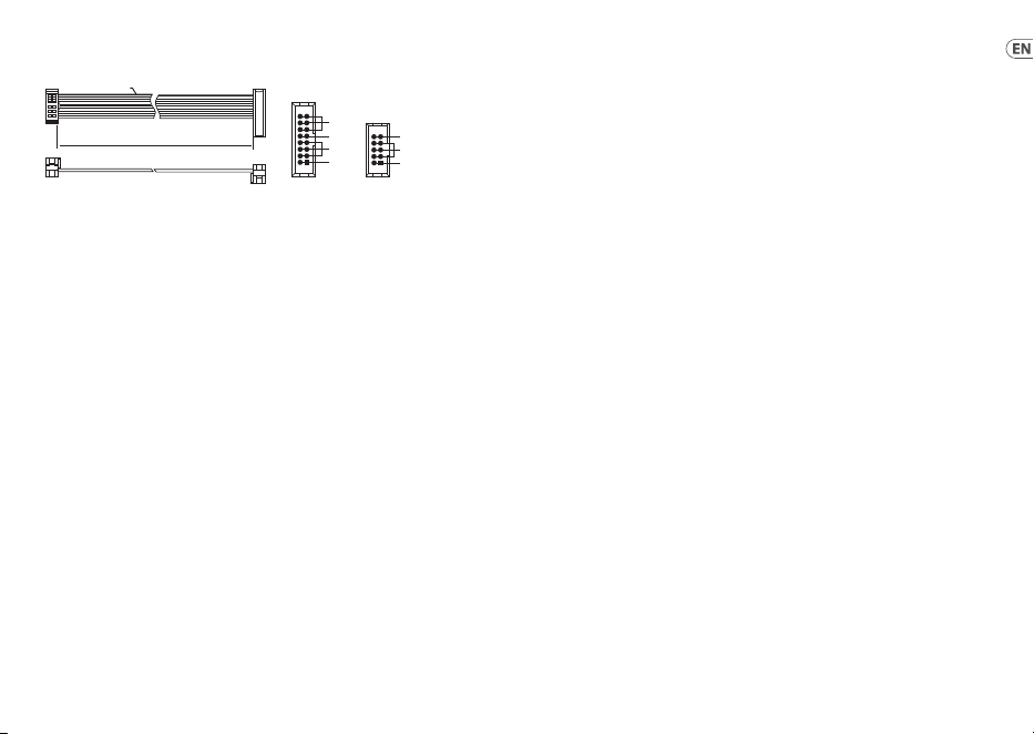
44 45Quick Start Guide
FOUR LFO
Power Connection
The module comes with the required power cable for connecting to a standard
Eurorack power supply system. Follow these steps to connect power to the
module. It is easier to make these connections before the module has been
mounted into a rack case.
1. Turn the power supply or rack case power o and disconnect the
power cable.
2. Insert the 16-pin connector on the power cable into the socket on the
power supply or rack case. The connector has a tab that will align with the
gap in the socket, so it cannot be inserted incorrectly. If the power supply
does not have a keyed socket, be sure to orient pin 1 (-12 V) with the red
stripe on the cable.
3. Insert the 10-pin connector into the socket on the back of the module. The
connector has a tab that will align with the socket for correct orientation.
4. After both ends of the power cable have been securely attached, you may
mount the module in a case and turn on the power supply.
Installation
The necessary screws are included with the module for mounting in a Eurorack
case. Connect the power cable before mounting.
Depending on the rack case, there may be a series of xed holes spaced 2 HP apart
along the length of the case, or a track that allows individual threaded plates to
slide along the length of the case. The free-moving threaded plates allow precise
positioning of the module, but each plate should be positioned in the approximate
relation to the mounting holes in your module before attaching the screws.
Hold the module against the Eurorack rails so that each of the mounting holes
are aligned with a threaded rail or threaded plate. Attach the screws part way to
start, which will allow small adjustments to the positioning while you get them all
aligned. After the nal position has been established, tighten the screws down.
HOT USED
Red Stripe
200 mm ± 10
15 16
21
P2P1
2
10 9
1
Connect end P1 to the module socket
Connect end P2 to the power supply
+ 12V
- 12V
GROUND
+ 12V
- 12V
GROUND
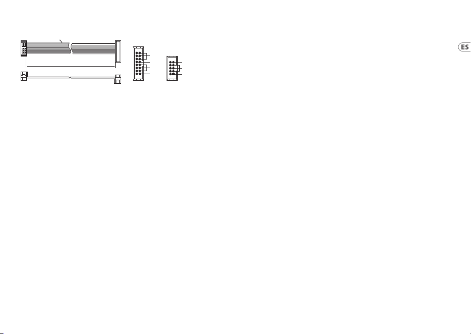
46 47Quick Start Guide
FOUR LFO
Conexión Eléctrica
El módulo viene con el cable de alimentación necesario para conectarse a un
sistema de suministro de energía Eurorack estándar. Siga estos pasos para
conectar la alimentación al módulo. Es más fácil realizar estas conexiones antes de
que el módulo se haya montado en una caja de rack.
1. Apague la fuente de alimentación o la caja del bastidor y desconecte el
cable de alimentación.
2. Inserte el conector de 16 clavijas del cable de alimentación en la toma de
la fuente de alimentación o en la caja del bastidor. El conector tiene una
pestaña que se alineará con el espacio en el zócalo, por lo que no se puede
insertar incorrectamente. Si la fuente de alimentación no tiene un enchufe
con llave, asegúrese de orientar el pin 1 (-12 V) con la raya roja en el cable.
3. Inserte el conector de 10 pines en el zócalo en la parte posterior del
módulo. El conector tiene una pestaña que se alineará con el enchufe para
una orientación correcta.
4. Una vez que ambos extremos del cable de alimentación se hayan
conectado de forma segura, puede montar el módulo en una caja y
encender la fuente de alimentación.
Instalación
Los tornillos necesarios se incluyen con el módulo para su montaje en una caja
Eurorack. Conecte el cable de alimentación antes del montaje.
Dependiendo de la caja del bastidor, puede haber una serie de oricios jos
separados 2 HP a lo largo de la caja, o una pista que permita que las placas
roscadas individuales se deslicen a lo largo de la caja. Las placas roscadas de
movimiento libre permiten un posicionamiento preciso del módulo, pero cada
placa debe colocarse en una relación aproximada con los oricios de montaje en su
módulo antes de colocar los tornillos.
Sostenga el módulo contra los rieles Eurorack de modo que cada uno de los
oricios de montaje esté alineado con un riel o placa roscada. Coloque los tornillos
parcialmente para comenzar, lo que permitirá pequeños ajustes en la posición
mientras los alinea todos. Una vez establecida la posición nal, apriete los tornillos.
HOT USED
Red Stripe
200 mm ± 10
15 16
21
P2P1
2
10 9
1
Connect end P1 to the module socket
Connect end P2 to the power supply
+ 12V
- 12V
GROUND
+ 12V
- 12V
GROUND

48 49Quick Start Guide
FOUR LFO
HOT USED
Red Stripe
200 mm ± 10
15 16
21
P2P1
2
10 9
1
Connect end P1 to the module socket
Connect end P2 to the power supply
+ 12V
- 12V
GROUND
+ 12V
- 12V
GROUND
Connexion Électrique
Le module est livré avec le câble d’alimentation requis pour la connexion à un
système d’alimentation standard Eurorack. Suivez ces étapes pour connecter
l’alimentation au module. Il est plus facile d’eectuer ces connexions avant que le
module n’ait été monté dans un boîtier de rack.
1. Mettez le bloc d’alimentation ou le boîtier de rack hors tension et
débranchez le câble d’alimentation.
2. Insérez le connecteur à 16 broches du câble d’alimentation dans la prise du
bloc d’alimentation ou du boîtier du rack. Le connecteur a une languette
qui s’alignera avec l’espace dans la prise, de sorte qu’il ne peut pas être
inséré de manière incorrecte. Si le bloc d’alimentation n’a pas de prise à
clé, veillez à orienter la broche 1 (-12 V) avec la bande rouge sur le câble.
3. Insérez le connecteur à 10 broches dans la prise à l’arrière du module.
Le connecteur a une languette qui s’alignera avec la prise pour une
orientation correcte.
4. Une fois que les deux extrémités du câble d’alimentation ont été
solidement xées, vous pouvez monter le module dans un boîtier et
allumer l’alimentation.
Installation
Les vis nécessaires sont incluses avec le module pour le montage dans un boîtier
Eurorack. Connectez le câble d’alimentation avant le montage.
Selon le cas de rack, il peut y avoir une série de trous xes espacés de 2 HP sur la
longueur du cas, ou une piste qui permet aux plaques letées individuelles de
glisser le long de la longueur du cas. Les plaques letées à déplacement libre
permettent un positionnement précis du module, mais chaque plaque doit être
positionnée approximativement par rapport aux trous de montage de votre
module avant de xer les vis.
Maintenez le module contre les rails Eurorack de sorte que chacun des trous
de montage soit aligné avec un rail leté ou une plaque letée. Fixez les vis
partiellement pour commencer, ce qui permettra de petits ajustements au
positionnement pendant que vous les alignerez tous. Une fois la position nale
établie, serrez les vis vers le bas.
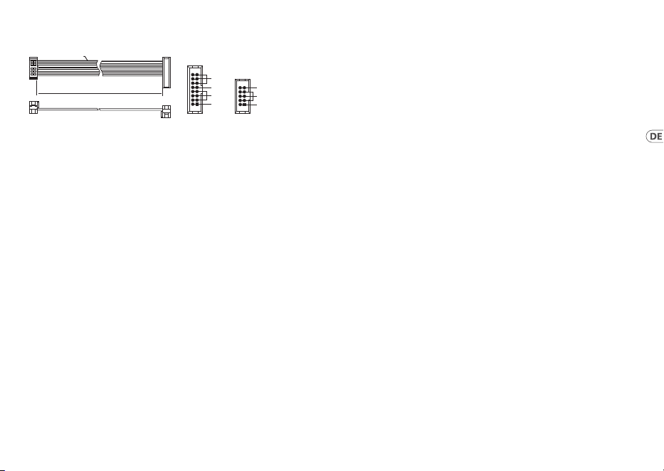
50 51Quick Start Guide
FOUR LFO
HOT USED
Red Stripe
200 mm ± 10
15 16
21
P2P1
2
10 9
1
Connect end P1 to the module socket
Connect end P2 to the power supply
+ 12V
- 12V
GROUND
+ 12V
- 12V
GROUND
Netzanschluss
Das Modul wird mit dem erforderlichen Stromkabel für den Anschluss an ein
Standard-Eurorack-Stromversorgungssystem geliefert. Befolgen Sie diese Schritte,
um das Modul mit Strom zu versorgen. Es ist einfacher, diese Verbindungen
herzustellen, bevor das Modul in ein Rackgehäuse eingebaut wurde.
1. Schalten Sie das Netzteil oder das Rackgehäuse aus und ziehen Sie das
Netzkabel ab.
2. Stecken Sie den 16-poligen Stecker am Netzkabel in die Buchse am Netzteil
oder im Rack-Gehäuse. Der Anschluss verfügt über eine Lasche, die an der
Lücke in der Buchse ausgerichtet ist, sodass sie nicht falsch eingesetzt
werden kann. Wenn das Netzteil keine Schlüsselbuchse hat, achten Sie
darauf, Pin 1 (-12 V) mit dem roten Streifen am Kabel auszurichten.
3. Stecken Sie den 10-poligen Stecker in die Buchse auf der Rückseite
des Moduls. Der Anschluss verfügt über eine Lasche, die zur korrekten
Ausrichtung an der Buchse ausgerichtet wird.
4. Nachdem beide Enden des Netzkabels fest angeschlossen wurden, können Sie
das Modul in einem Gehäuse montieren und die Stromversorgung einschalten.
Installation
Die erforderlichen Schrauben sind im Lieferumfang des Moduls für die Montage in
einem Eurorack-Gehäuse enthalten. Schließen Sie das Netzkabel vor der Montage an.
Abhängig vom Rack-Gehäuse kann es eine Reihe von festen Löchern geben, die
entlang der Länge des Gehäuses 2 PS voneinander entfernt sind, oder eine Schiene, mit
der einzelne Gewindeplatten entlang der Länge des Gehäuses gleiten können. Die frei
beweglichen Gewindeplatten ermöglichen eine präzise Positionierung des Moduls.
Jede Platte sollte jedoch in der ungefähren Beziehung zu den Befestigungslöchern in
Ihrem Modul positioniert werden, bevor Sie die Schrauben anbringen.
Halten Sie das Modul so gegen die Eurorack-Schienen, dass jedes der
Befestigungslöcher mit einer Gewindeschiene oder einer Gewindeplatte
ausgerichtet ist. Bringen Sie die Schrauben teilweise an, um zu beginnen. Dadurch
können Sie die Position geringfügig anpassen, während Sie alle ausrichten. Ziehen
Sie die Schrauben fest, nachdem die endgültige Position festgelegt wurde.

52 53Quick Start Guide
FOUR LFO
HOT USED
Red Stripe
200 mm ± 10
15 16
21
P2P1
2
10 9
1
Connect end P1 to the module socket
Connect end P2 to the power supply
+ 12V
- 12V
GROUND
+ 12V
- 12V
GROUND
Conexão de Força
O módulo vem com o cabo de alimentação necessário para conectar a um sistema de
fonte de alimentação Eurorack padrão. Siga estas etapas para conectar a alimentação
ao módulo. É mais fácil fazer essas conexões antes que o módulo seja montado em
um gabinete de rack.
1. Desligue a fonte de alimentação ou o gabinete do rack e desconecte o cabo
de alimentação.
2. Insira o conector de 16 pinos do cabo de alimentação no soquete da fonte
de alimentação ou no gabinete do rack. O conector possui uma aba que
se alinhará com a lacuna no soquete, portanto, não pode ser inserido
incorretamente. Se a fonte de alimentação não tiver um soquete chaveado,
certique-se de orientar o pino 1 (-12 V) com a faixa vermelha no cabo.
3. Insira o conector de 10 pinos no soquete na parte traseira do módulo. O
conector possui uma guia que se alinha ao soquete para orientação correta.
4. Depois que ambas as extremidades do cabo de alimentação forem
conectadas com segurança, você pode montar o módulo em uma caixa e
ligar a fonte de alimentação.
Instalação
Os parafusos necessários estão incluídos com o módulo para montagem em uma
caixa Eurorack. Conecte o cabo de alimentação antes da montagem.
Dependendo da caixa do rack, pode haver uma série de orifícios xos espaçados
de 2 HP ao longo do comprimento da caixa, ou um trilho que permite que placas
roscadas individuais deslizem ao longo do comprimento da caixa. As placas roscadas
de movimento livre permitem o posicionamento preciso do módulo, mas cada placa
deve ser posicionada em relação aproximada aos orifícios de montagem em seu
módulo antes de prender os parafusos.
Segure o módulo contra os trilhos Eurorack de forma que cada um dos orifícios
de montagem quem alinhados com um trilho ou placa rosqueada. Prenda os
parafusos parcialmente para começar, o que permitirá pequenos ajustes no
posicionamento enquanto você os alinha. Depois de estabelecida a posição nal,
aperte os parafusos.

54 55Quick Start Guide
FOUR LFO
HOT USED
Red Stripe
200 mm ± 10
15 16
21
P2P1
2
10 9
1
Connect end P1 to the module socket
Connect end P2 to the power supply
+ 12V
- 12V
GROUND
+ 12V
- 12V
GROUND
Connessione di Alimentazione
Il modulo viene fornito con il cavo di alimentazione necessario per il collegamento
a un sistema di alimentazione Eurorack standard. Seguire questi passaggi per
collegare l’alimentazione al modulo. È più facile eettuare questi collegamenti
prima che il modulo sia stato montato in un case rack.
1. Spegnere l’alimentatore o il case del rack e scollegare il cavo di alimentazione.
2. Inserire il connettore a 16 pin del cavo di alimentazione nella presa
sull’alimentatore o sulla custodia del rack. Il connettore ha una linguetta
che si allineerà con lo spazio nella presa, quindi non può essere inserito
in modo errato. Se l’alimentatore non dispone di una presa con chiave,
assicurarsi di orientare il pin 1 (-12 V) con la striscia rossa sul cavo.
3. Inserire il connettore a 10 pin nella presa sul retro del modulo.
Il connettore ha una linguetta che si allineerà con la presa per un corretto
orientamento.
4. Dopo che entrambe le estremità del cavo di alimentazione sono state
ssate saldamente, è possibile montare il modulo in una custodia e
accendere l’alimentatore.
Installazione
Le viti necessarie sono incluse con il modulo per il montaggio in una custodia
Eurorack. Collegare il cavo di alimentazione prima del montaggio.
A seconda del case del rack, potrebbero esserci una serie di fori ssi distanziati di
2 HP l’uno dall’altro lungo la lunghezza del case, o un binario che consente alle
singole piastre lettate di scorrere lungo la lunghezza del case. Le piastre lettate
a movimento libero consentono un posizionamento preciso del modulo, ma
ciascuna piastra deve essere posizionata in relazione approssimativa con i fori di
montaggio nel modulo prima di ssare le viti.
Tenere il modulo contro le guide Eurorack in modo che ciascuno dei fori di
montaggio sia allineato con una guida lettata o una piastra lettata. Attacca le
viti in parte per iniziare, il che consentirà piccoli aggiustamenti al posizionamento
mentre le fai allineare tutte. Dopo aver stabilito la posizione nale, serrare le viti.
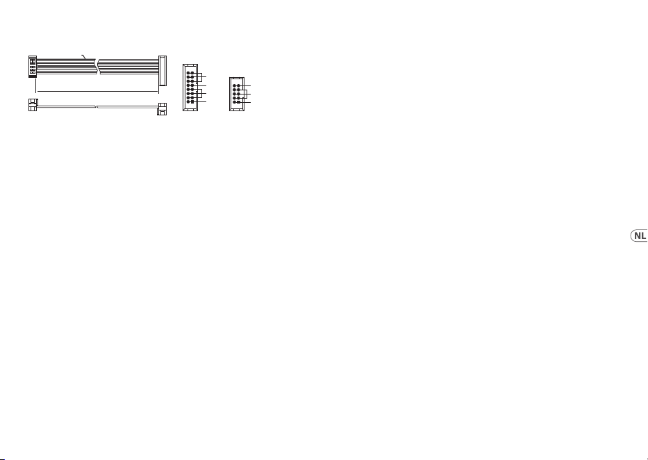
56 57Quick Start Guide
FOUR LFO
HOT USED
Red Stripe
200 mm ± 10
15 16
21
P2P1
2
10 9
1
Connect end P1 to the module socket
Connect end P2 to the power supply
+ 12V
- 12V
GROUND
+ 12V
- 12V
GROUND
Stroomaansluiting
De module wordt geleverd met de benodigde voedingskabel voor aansluiting op
een standaard Eurorack-voedingssysteem. Volg deze stappen om de module van
stroom te voorzien. Het is gemakkelijker om deze aansluitingen te maken voordat
de module in een rekbehuizing is gemonteerd.
1. Schakel de voeding of de rekbehuizing uit en koppel de voedingskabel los.
2. Steek de 16-pins connector van de voedingskabel in de aansluiting op
de voedingseenheid of rekbehuizing. De connector heeft een lipje dat
wordt uitgelijnd met de opening in de socket, zodat deze niet verkeerd
kan worden geplaatst. Als de voeding geen contactdoos met sleutel heeft,
zorg er dan voor dat pen 1 (-12 V) met de rode streep op de kabel wordt
georiënteerd.
3. Steek de 10-pins connector in de aansluiting aan de achterkant van de
module. De connector heeft een lipje dat uitgelijnd is met de aansluiting
voor de juiste oriëntatie.
4. Nadat beide uiteinden van de voedingskabel stevig zijn bevestigd, kunt u
de module in een hoesje monteren en de voeding inschakelen.
Installatie
De benodigde schroeven worden bij de module geleverd voor montage in een
Eurorack-koer. Sluit de voedingskabel aan voor montage.
Afhankelijk van de rackbehuizing kan er een reeks vaste gaten zijn die 2 HP uit
elkaar liggen over de lengte van de behuizing, of een rail waarmee afzonderlijke
platen met schroefdraad langs de lengte van de behuizing kunnen schuiven. De
vrij bewegende plaatjes met schroefdraad maken een nauwkeurige positionering
van de module mogelijk, maar elke plaat moet ongeveer in verhouding tot de
montagegaten in uw module worden geplaatst voordat u de schroeven bevestigt.
Houd de module tegen de Eurorack-rails zodat elk van de montagegaten is
uitgelijnd met een rail met schroefdraad of een plaat met schroefdraad. Bevestig
de schroeven halverwege om te beginnen, waardoor kleine aanpassingen aan
de positionering mogelijk zijn terwijl u ze allemaal op één lijn krijgt. Nadat de
denitieve positie is bepaald, draait u de schroeven vast.
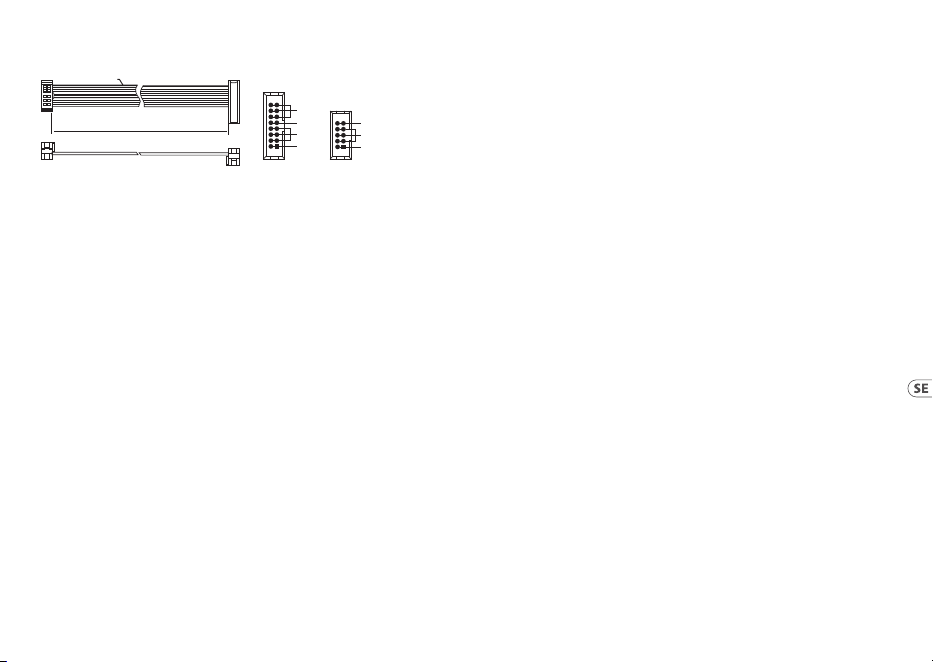
58 59Quick Start Guide
FOUR LFO
HOT USED
Red Stripe
200 mm ± 10
15 16
21
P2P1
2
10 9
1
Connect end P1 to the module socket
Connect end P2 to the power supply
+ 12V
- 12V
GROUND
+ 12V
- 12V
GROUND
Strömanslutning
Modulen levereras med den strömkabel som krävs för att ansluta till ett vanligt
Eurorack-nätaggregat. Följ dessa steg för att ansluta ström till modulen. Det är
lättare att göra dessa anslutningar innan modulen har monterats i ett rackfodral.
1. Stäng av strömmen eller rackhöljet och koppla bort strömkabeln.
2. Sätt i den 16-poliga kontakten på strömkabeln i uttaget på
nätaggregatet eller rackfodralet. Kontaktdonet har en ik som kommer
i linje med springan i uttaget så att den inte kan sättas in felaktigt.
Om strömförsörjningen inte har ett nyckeluttag, se till att orientera
stift 1 (-12 V) med den röda remsan på kabeln.
3. Sätt i 10-polig kontakt i uttaget på baksidan av modulen. Kontaktdonet
har en ik som kommer i linje med uttaget för korrekt orientering.
4. När båda ändarna av strömkabeln har anslutits ordentligt kan du montera
modulen i ett fodral och slå på strömförsörjningen.
Installation
De nödvändiga skruvarna ingår i modulen för montering i ett Eurorack-fodral.
Anslut strömkabeln före montering.
Beroende på stativhöljet kan det nnas en serie fasta hål som är åtskilda 2
hk längs höljets längd eller ett spår som gör att enskilda gängade plattor kan
glida längs höljets längd. De fritt rörliga gängade plattorna möjliggör exakt
positionering av modulen, men varje platta bör placeras i ungefärlig relation till
monteringshålen i din modul innan skruvarna fästs.
Håll modulen mot Eurorack-skenorna så att var och en av monteringshålen ligger i
linje med en gängad skena eller gängad platta. Fäst skruvarna delvis för att börja,
vilket gör det möjligt att justera små positioner medan du justerar dem alla. När
den slutliga positionen har fastställts drar du åt skruvarna.
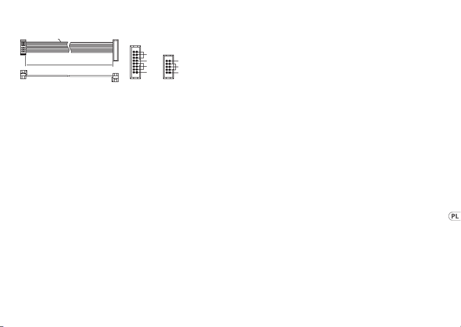
60 61Quick Start Guide
FOUR LFO
HOT USED
Red Stripe
200 mm ± 10
15 16
21
P2P1
2
10 9
1
Connect end P1 to the module socket
Connect end P2 to the power supply
+ 12V
- 12V
GROUND
+ 12V
- 12V
GROUND
Podłączenie Zasilania
Do modułu dołączony jest wymagany kabel zasilający do podłączenia do
standardowego systemu zasilania Eurorack. Wykonaj poniższe czynności,
aby podłączyć zasilanie do modułu. Łatwiej jest wykonać te połączenia przed
zamontowaniem modułu w obudowie rack.
1. Wyłącz zasilacz lub obudowę szafy i odłącz kabel zasilający.
2. Włóż 16-stykowe złącze przewodu zasilającego do gniazda w zasilaczu
lub w szae typu rack. Złącze ma wypustkę, która będzie wyrównana ze
szczeliną w gnieździe, więc nie można jej nieprawidłowo włożyć. Jeśli
zasilacz nie ma gniazda z kluczem, należy zorientować styk 1 (-12 V) z
czerwonym paskiem na kablu.
3. Włóż 10-pinowe złącze do gniazda z tyłu modułu. Złącze ma wypustkę,
która będzie wyrównana z gniazdem, aby zapewnić prawidłową orientację.
4. Po solidnym zamocowaniu obu końców kabla zasilającego można
zamontować moduł w obudowie i włączyć zasilacz.
Instalacja
Do modułu dołączone są niezbędne śruby do montażu w skrzynce Eurorack.
Podłącz kabel zasilający przed montażem.
W zależności od obudowy szafy może występować szereg stałych otworów
rozmieszczonych w odstępach 2 HP na całej długości obudowy lub prowadnica,
która umożliwia przesuwanie pojedynczych gwintowanych płyt wzdłuż całej
obudowy. Swobodnie poruszające się gwintowane płytki umożliwiają precyzyjne
ustawienie modułu, ale każda płyta powinna być ustawiona w przybliżeniu w
stosunku do otworów montażowych w module przed przykręceniem śrub.
Przytrzymaj moduł na szynach Eurorack, tak aby każdy z otworów montażowych
był wyrównany z szyną gwintowaną lub płytą gwintowaną. Wkręć śruby
częściowo, aby rozpocząć, co pozwoli na drobne korekty położenia, gdy wszystkie
zostaną wyrównane. Po ustaleniu ostatecznego położenia dokręcić śruby.

62 63Quick Start Guide
FOUR LFO
HOT USED
Red Stripe
200 mm ± 10
15 16
21
P2P1
2
10 9
1
Connect end P1 to the module socket
Connect end P2 to the power supply
+ 12V
- 12V
GROUND
+ 12V
- 12V
GROUND
電源接続
モ ジ ュ ー ル に は 、標 準 の Eurorack 電 源システムに接 続 するために 必 要
な 電 源 ケーブルが 付 属しています。以下の 手 順 に 従って、モ ジュール を
Eurorack ケースに 接 続します。
1. 電源またはラックケースの電源を切り、電源ケーブルを外します。
2. 電源 ケーブル の 16 ピンコネクタを電源装置またはラックケース
のソケ ットに 差し 込 み ます。コネクタには 、ソケットの ギ ャップ に
合わせて配置されるタブがあるため、正しく挿入することはでき
ません。電源装置にキー付きソケットがない場合は、ケーブルの
赤いストライプ をピン 1 (-12 V) に 向 け て 指 定してください 。
3. モジュール背面のソケットに 10 ピンコネクタを挿入します。コネ
ク タ に は 、正 し い 方 向 を 取 り 付 け る ソ ケ ット に 合 わ せ て 配 置 す る
タブが あります。
4. 電源ケーブルの両端がしっかりと接続されたら、モジュールをケ
ースに取り付けて 電 源 を 入 れ ま す。
インストール
必要なネジは、ユーロラックケースに取り付けるためのモジュールに付
属しています。取り付 ける前に電 源 ケーブルを接 続します。
ラックケースによって は 、ケースの 長さに 沿 って 2 HP 間隔をあけた一連
の 固 定 穴 や 、個 々 の ね じ 板 が ケ ー ス の 長 さ に 沿 っ て ス ラ イ ド で き る ト ラ
ックが存在する場合 があります。自由に動くねじ板はモジュールの正
確な位置を可能にするが、各版はねじを取り付ける前にモジュールの
取付け穴に近い関係で置かれるべきである。
取り付け穴のそれぞれがねじ付きレールまたはねじ板に合うように、
ユーロラックレールに対してモジュールを保持します。ねじを途中で取
り付けて開始し、位置を微調整しながら、すべての位置合わせを行い
ます。最終的な位置が決まってきた後、ネジを締め付けて下ろします。

64 65Quick Start Guide
FOUR LFO
HOT USED
Red Stripe
200 mm ± 10
15 16
21
P2P1
2
10 9
1
Connect end P1 to the module socket
Connect end P2 to the power supply
+ 12V
- 12V
GROUND
+ 12V
- 12V
GROUND
电源连接
该模块配备了连接到标准 Eurorack 电源系统所需的电源线。 按照这些步
骤将模块连接到您的 Eurorack 案例。
1. 关闭电源或机架外壳电源并断开电源电缆。
2. 将电源线上的 16 针连接器插入电源或机架盒上的插座中。 连
接器有一个选项卡, 该选项卡将与插座中 的间隙对齐, 因此不能
错误地插入该选项卡。 如果电源没有钥匙插座, 请务必将引脚
1 (-12 V) 定向到电缆上的红色条纹上。
3. 将 10 针连接器插入模块背面的插座中。 连接器有一个选项卡,
该选项卡将与插座对齐以获得正确的方向。
4. 电源线的两端牢固连接后, 您可以在情况下安装模块并打开电源。
安装
必要的螺丝包含在用于安装在欧洲拉克箱中的模块中。 安装前连接电源线。
根据机架外壳的不同, 可能会有一系列固定孔, 沿着机箱的长度间隔
2 HP, 或允许单个螺纹板沿外壳长度滑动的轨道。 自由移动的螺纹板允
许模块的精确定位, 但在连接螺丝之前, 每个板应定位在与模块安装
孔的大致关系中。
将模块与 Eurorack 导轨对立, 以便每个安装孔与螺纹导轨或螺纹板
对齐。 将螺丝部分连接以开始, 这将允许在调整它们时对定位进行小
调整。 确定最终位置后, 拧紧螺丝。
66 67Quick Start Guide
FOUR LFO
Inputs
CV in
Type 4 x 3.5 mm TS jacks, DC coupled
Impedance >1 MΩ, unbalanced
Max input level 10 V p-p
Reset/Sync In
Type 4 x 3.5 mm TS jack, DC coupled
Impedance >1 MΩ, unbalanced
Max input level 10 V p-p
Outputs
Sine Out
Type 4 x 3.5 mm TS jack, DC coupled
Impedance >1 MΩ, unbalanced
Max output level 10 V p-p
Assign Out
Type 4 x 3.5 mm TS jack, DC coupled
Impedance >1 MΩ, unbalanced
Max output level 10 V p-p
Square Out
Type 4 x 3.5 mm TS jack, DC coupled
Impedance >1 MΩ, unbalanced
Max output level 10 V p-p
Controls
Sliders 4 x function attenuator
Switches
Mode (Reset/Sync) / Assign
(ramp, saw, triangle, trapezoid)
Button Function (Free, Quad, Phase, Divide)
LED Function (Free, Quad, Phase, Divide)
Power
Power supply Eurorack
Current draw 95 mA (+12 V) and 69 mA (-12 V)
Physical
Dimensions
71.12 x 128.5 x 32.6 mm
(2.80 x 5.05 x 1.28")
Rack units 14 HP
Weight 0.14 kg (0.31 lbs)
Specications
68 69Quick Start Guide
FOUR LFO
技术参数
输入
简历
类型
4 个 3.5 mm TS 插孔, 直流耦合
阻抗
>1 MΩ, 不平衡
最大输入电平
10 V p-p
重置/同步
类型
4 x 3.5 mm TS 插孔, 直流耦合
阻抗
>1 MΩ, 不平衡
最大输入电平
10 V p-p
输出
正弦输出
类型
4 x 3.5 mm TS 插孔, 直流耦合
阻抗
>1 MΩ, 不平衡
最大输出电平
10 V p-p
分配出去
类型
4 x 3.5 mm TS 插孔, 直流耦合
阻抗
>1 MΩ, 不平衡
最大输出电平
10 V p-p
平方输出
类型
4 x 3.5 mm TS 插孔, 直流耦合
阻抗
>1 MΩ, 不平衡
最大输出电平
10 V p-p
控制
滑 块
4 x 功能衰减器
开关
模式 (复位/同步)/分配
(斜坡、 锯、 三角形、 梯形)
按钮
功能 (自由、 四通道、
相位、 分频)
发光二极管
功能 (自由、 四通道、
相位、 分频)
权力
电源 欧罗拉克
电流消耗
95 mA (+12 V) and 69 mA (-12 V)
物理的
尺寸
71.12 x 128.5 x 32.6 mm
(2.80 x 5.05 x 1.28")
机架单元
14 HP
重量
0.14 kg (0.31 lbs)
70 71Quick Start Guide
FOUR LFO
FEDERAL COMMUNICATIONS
COMMISSION COMPLIANCE INFORMATION
Responsible Party Name:
Music Tribe Commercial NV Inc.
Address:
122 E. 42nd St.1, 8th Floor NY,
NY 10168, United States
Email Address:
FOUR LFO
This equipment has been tested and found
to comply with the limits for a Class B
digital device, pursuant to part 15 of the FCC
Rules. These limits are designed to provide
reasonable protection against harmful
interference in a residential installation.
This equipment generates, uses and can
radiate radio frequency energy and, if not
installed and used in accordance with the
instructions, may cause harmful interference
to radio communications. However, there is
no guarantee that interference will not occur
in a particular installation. If this equipment
does cause harmful interference to radio or
television reception, which can be determined
by turning the equipment o and on, the user
is encouraged to try to correct the interference
by one or more of the following measures:
• •
Reorient or relocate the receiving antenna.
• •
Increase the separation between the
equipment and receiver.
• •
Connect the equipment into an outlet on
a circuit dierent from that to which the
receiver is connected.
• •
Consult the dealer or an experienced
radio/TV technician for help.
This equipment complies with Part 15 of the
FCC rules. Operation is subject to the following
two conditions:
(1) this device may not cause harmful
interference, and
(2) this device must accept any interference
received, including interference that may
cause undesired operation.
Important information:
Changes or modications to the equipment not
expressly approved by Music Tribe can void the
user’s authority to use the equipment.
Hereby, Music Tribe declares that this
product is in compliance with Directive
2014/30/EU, Directive 2011/65/EU and
Amendment 2015/863/EU, Directive
2012/19/EU, Regulation 519/2012 REACH SVHC
and Directive 1907/2006/EC.
Full text of EU DoC is available at
https://community.musictribe.com/
EU Representative: Music Tribe Brands DK A/S
Address: Gammel Strand 44, DK-1202
København K, Denmark
UK Representative: Music Tribe Brands UK Ltd.
Address: 8th Floor, 20 Farringdon Street
London EC4A 4AB, United Kingdom
Behringer
FOUR LFO
Correct disposal of this product:
This symbol indicates that this
product must notbe disposed of
with household waste, according
to the WEEE Directive
(2012/19/EU) and your national law.
Thisproduct should be taken to a collection
center licensed for the recycling of waste
electrical and electronic equipment (EEE).
Themishandling of this type of waste could
have a possible negative impact on the
environment and human health due to
potentially hazardous substances that are
generally associated with EEE. At the same
time, your cooperation in the correct disposal
of this product will contribute to the ecient
use of natural resources. For more information
about where you can take your waste
equipment for recycling, please contact your
local city oce, or your household waste
collection service.
型 号: FOUR LFO 合成器与采样器
制造商: Empower Tribe Commercial FZE –
Made in China 中国制造
CAN ICES–003 (B)/NMB–003 (B)

We Hear You