
Technical Support and E-Warranty Certificate www.vevor.com/support
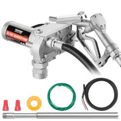
FUEL TRANSFER PUMP(Single)
OWNERS INSTALLATION,
OPERATION, AND SAFETY MANUAL
MODEL:KEX-20
We continue to be committed to provide you tools with competitive price.
"Save Half", "Half Price" or any other similar expressions used by us only represents an
estimate of savings you might benefit from buying certain tools with us compared to the major
top brands and does not necessarily mean to cover all categories of tools offered by us. You
are kindly reminded to verify carefully when you are placing an order with us if you are
actually saving half in comparison with the top major brands.

-
1
-
This is the original instruction, please read all manual instructions
carefully before operating. VEVOR reserves a clear interpretation of our
user manual. The appearance of the product shall be subject to the
product you received. Please forgive us that we won't inform you again if
there are any technology or software updates on our product.
FUEL TRANSFER PUMP
MODEL: KEX-20
Have product questions? Need technical support? Please feel free to
contact us:
Technical Support and E-Warranty Certificate
www.vevor.com/support
NEED HELP? CONTACT US!

-
2
-
SAFETY INFORMATION
WARNING! Electrical wiring should be performed ONLY by a
licensed electrician in compliance with local, state, and national
electrical code NEC/ANSI/ NFPA 70, NFPA 30, and NFPA 30A, as
appropriate to the intended use of the pump. Threaded rigid conduit,
sealed fittings, and conductor seal should be used where applicable.
The pump must be properly grounded. Improper installation or use of
this pump can result in serious bodily injury, or death!
WARNING! To ensure safe and proper operation of your equipment,
it is critical to read and adhere to all of the following safety warnings and
precautions. Improper installation or use of this product can cause
serious bodily injury or death!
NEVER smoke near the pump, or use the pump near open flames
when pumping a flammable liquid! Fire can result!
A filter should be used on the pump outlet to ensure no foreign
material is transferred to the fuel tank.
Threaded pipe joints and connections must be sealed with the
appropriate sealant or sealant tape to minimize the possibility of
leaks.
Storage tanks must be securely anchored to prevent shifting or
tipping when full or empty.
To minimize static electricity build up, use only static wire conductive
hose when pumping flammable fluids, and keep the fill nozzle in
contact with the container being filled during the filling process.
The pump motor is equipped with thermal overload protection; if
overheated, the motor will shut off to prevent damage to the
windings.

-
3
-
INSTALLATION
WARNING! This product shall not be used to transfer fluids into
any type of aircraft.
WARNING! This product is not suited for use with fluids intended
for human consumption or fluids containing water.
20GMP fuel transfer pump is designed to be mounted on a skid tank using
the threaded inlet flange supplied with the pump. Your pump features an
integral bypass valve to recirculate the fluid when the pump is operating
with the nozzle closed.
WARNING! This product is not suited for use with fluids intended
for human consumption or fluids containing water.
CAUTION! Do not use additional check valves or foot valves
unless they have a proper pressure relief valve built into them. Note that
additional check valves will reduce rate of flow.

-
4
-
CAUTION! A pressure retaining fill cap can be used to reduce fuel
loss through evaporation, but note that it will reduce the flow rate.
CAUTION! Threaded pipe joints and connections must be sealed
with the appropriate sealant or sealant tape to prevent the possibility of
leaks.
WARNING! 20GMP fuel transfer pumps are designed for use with
stationary and mobile tank applications. While DC powered units are
excellent choice for mobile applications, anchoring the tank to which the
pump is mounted is paramount to ensure no movement in transit.
Failure to secure the tank to the vehicle can cause uncontrolled
movement, resulting in damage, injury, and potential fire.

-
5
-
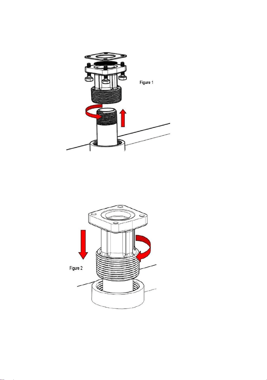
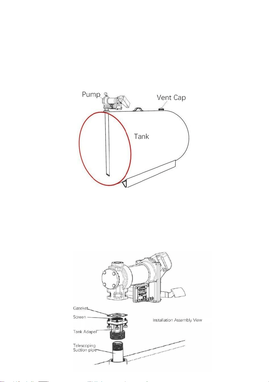
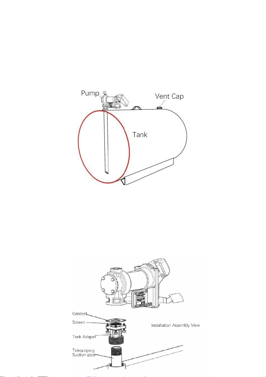
Typical Skid Tank Installation
The pump mounts to the bung of a skid tank by way of the inlet flange. The
suction tube threads into the bottom of the inlet flange, and must extend to
a length that positions it at least 3” from the bottom of the tank. The skid
tank should be equipped with a vent cap.
Materials:
1” telescoping suction pipe extended to a length that will extend to
within 3” of the bottom of the tank when screwed into the tank adapter
with the tank adapter screwed into the tank flange (see SKID TANK
INSTALLATION diagram).
Threaded pipe joint sealant appropriate for application.
-
6
-
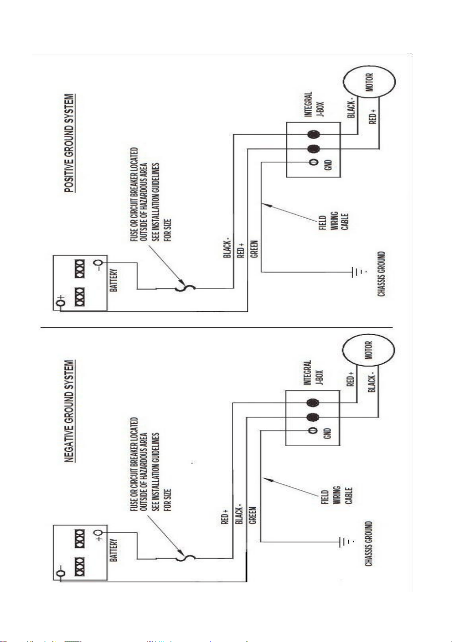
Installation Procedure:
1. Thread the 1” pipe into the tank adapter. Seal threads liquid tight with
appropriate sealant. (Figure 1)
Typical Skid Tank Installation (cont’d)
2. Screw the inlet flange (with suction pipe) into the tank bung; seal
threads liquid tight with appropriate thread sealant (Figure 2).

-
7
-
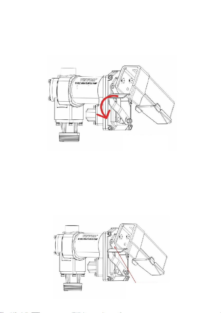
ELECTRICAL WIRING
3. Mount the pump on the adapter; making sure the seal and screen are
installed as shown. (Figure 3).
CAUTION! DC powered pumps are designed to operate on either
12 or 24 VDC (depending on model). Where applicable, use the
supplied battery cable to supply power to the pump from a 12 or 24
VDC battery. A 40 amp fuse (20 amp fuse on 24 VDC motors) should be
installed on the battery cable to protect the wire in case of electrical
short.

-
8
-
CAUTION! Voltage drop in wiring varies depending on the
distance from the battery to the pump and the gauge of the wire used. If
the distance is greater than 20’, refer to national, international, or local
electrical codes to ensure the wire is of the correct size for this
application.
Instructions Before Proceeding With DC Wiring
The pump needs to be electrically bonded to supply tank or vehicle frame.
To electrically bond pump, remove green bonding screw located next to
junction box cover. Insert this screw through eyelet of furnished green
bonding wire assembly and refasten it securely to the pump. The other end
of the wire is to be stripped of insulation and the bare wire securely bonded
to the vehicle / trailer frame or skid tank.
WARNING! Do not connect the positive or negative power to the
green screw or wire as this could cause a fire.
Wiring Instructions
1. Remove pump’s electrical junction box cover and straighten the 2
wires to make the stripped wire ends accessible outside of the
junction box.
2. Screw furnished cable connector into NPT* conduit opening in pump
junction box.
3. Strip 6 inches of the outer covering from one end of the furnished

-
9
-
electrical cable being careful not to damage the black and red wire
insulation.
4. Loosen cable connector nut and pass the stripped end of the furnished
cable through the cable connector. Tighten the cable connector nut.
5. Strip 1
⁄
2 inch of the insulation from the ends of the red and black cable
wires. Using the furnished wire nuts, connect these wires to the pump
wires matching the colors. Be sure no bare wire is exposed.
6. Fold wires into junction box and replace cover making sure the gasket
is in place. Make sure all screws are seated so there is no space
between the cover and the junction box.
Wiring To A Vehicle Electrical System
1. Pass the electrical wires to the source of the vehicle power system,
supporting the wires as necessary and protecting them from sharp
edges, heat, and anything that could damage the wires.
2. To determine if the vehicle electrical system is negative (-) or positive
(+) ground, check the battery marking of the terminal that is wired to
the vehicle frame or motor block. The red wire from the pump will
connect to positive battery post and the black wire from the pump will
connect to negative battery post.
3. Attach one end of the fuse holder to the end of the ungrounded wire.
Make a solid electrical connection with the other end of the fuse holder
to the ungrounded side of the battery, as close to the battery as
possible. Make a solid electrical connection to the grounded side of the
battery with the remaining wire. The battery terminal or the end of the
battery cable is recommended.
4. Check all connections to make sure they are connected per
instructions and all electrical codes. Install the 40 amp fuse (20 amp
fuse in 24 VDC installations) in the fuse holder. The installation is now
complete.

-
10
-
WARNING! Do not attempt to power the pump from vehicle wiring
smaller than 12 gage such as the cigarette lighter wire because these
thin wires could overheat and cause a fire.
DC Wiring (cont’d)
For Skid Mounted Tanks
1. Pass the electrical wires to the power source, supporting the wires as
necessary and protecting them from sharp edges, heat and anything
that could damage the wires.
2. Attach one end of the fuse holder to the red pump wire, as close to
the battery /power source as possible. Make a solid electrical
connection to the positive terminal of the power source with the other
end of the fuse holder. Make a solid connection with the black pump
wire to the negative terminal of the power source.
3. Check all connections to make sure they are connected per
instructions and all electrical codes. Install the 40 amp fuse (20 amp
fuse in 24 VDC installations) in the fuse holder. The installation is now
complete.

-
11
-
DC Wiring Diagram

-
12
-
WARNING! Always keep the nozzle in contact with the container
being filled during the filling process to minimize the possibility of static
electricity build up.
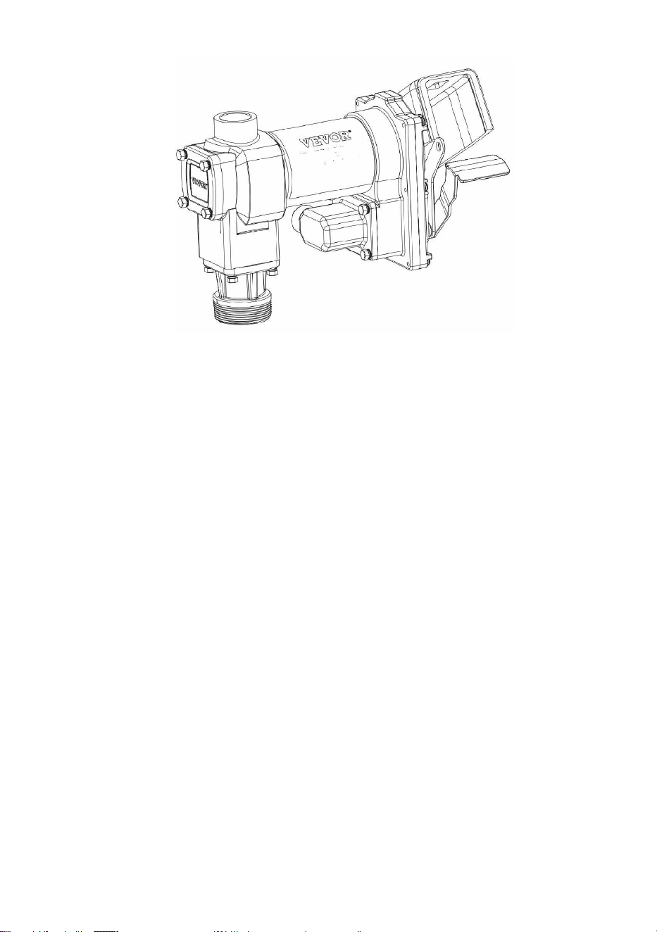
OPERATING INSTRUCTIONS
1.
If so equipped, reset meter to “0” (do not reset while in use as this will
cause damage to the meter).
2.Remove dispensing nozzle from nozzle boot.
3.Move the switch lever to the “ON” position to power the pump (figure 1).
4.Insert the dispensing nozzle into the container to be filled.
5.Operate the nozzle to dispense fluid; release nozzle when the desired
amount of fluid has been dispensed.
“ON”positiong
Figure 1

-
13
-
6.Move switch lever to the “OFF” position (Figure 2) to turn off the pump.
7.
Remove the dispensing nozzle from the container being filled and store it
in the nozzle boot.
Padlocking
Your pump nozzle can be padlocked to the pump for added security. With
the pump turned off, and the nozzle in the stored position, a padlock can be
inserted through the locking link and the nozzle handle.
The locking link is located on the nozzle side of the pump, and can be
pivoted into position to work with a variety of nozzles (Figure 3).
“OFF”positiong
Figure 2
locking Link
Figure 3

-
14
-
WARNING! DO NOT open or attempt to repair the motor on your
pump. Return it to the place of purchase for service. Opening the motor
case can compromise the integrity of the Explosion Proof construction
and will void any existing warranty and certification.
WARNING! Be certain all power to the pump is disconnected prior
to performing any service or maintenance.
TROUBLESHOOTING
The following troubleshooting guide is provided to offer basic diagnostic
assistance in the event you encounter abnormal service from your 20GMP
fuel transfer product.

-
15
-
Symptom
Cause
Cure
Pump won't
prime.
1. Suction line problem.
Check for leaks or obstructions in suction line.
2. Bypass valve open.
Remove and inspect valve; must move freely & be
free of debris.
3. Vanes sticking.
Check vanes and slots for nicks, burrs and wear.
4. Excessive rotor or vane
wear.
Inspect rotor & vanes for excessive wear or
damage; replace if necessary.
5. Vapor Lock.
Reduce vertical and horizontal distance from
pump to liquid; remove automatic nozzle.
Low capacity.
1. Excessive dirt in screen.
Remove and clean screen.
2. Suction line problem.
Check suction line for leaks or restrictions; it may
be too small, too long or not airtight.
3. Bypass valve sticking.
Remove and inspect valve; must move freely & be
free of debris.
4. Outlet blocked.
Check pump outlet, hose, nozzle & filter for
blockage.
5. Vanes sticking.
Check vanes and slots for wear.
6. Excessive rotor or vane
wear.
Inspect rotor & vanes for excessive wear or
damage; replace if necessary.
7. Hose or nozzle damage.
Replace hose or nozzle.
8. Plugged filter.
Replace filter.
9. Low fluid level.
Fill tank.
Pump runs
slowly.
1. Incorrect voltage.
Check incoming line voltage while pump is
running.
2. Vanes sticking.
Inspect vanes and slots for nicks, burrs and wear.
3. Wiring problem.
Check for loose connections.
4. Motor problem.
Return to place of purchase.

-
16
-
TROUBLESHOOTING (CONT’D)
Motor stalls / fuse
blows or thermal
protector trips
repeatedly.
1. Bypass valve sticking.
Remove and inspect valve; must move freely
& be free of debris.
2. Low voltage.
Check incoming line voltage while pump is
running.
3. Excessive rotor or vane wear.
Check rotor & vanes for excessive wear or
damage.
4. Debris in pump cavity.
Clean debris from pump cavity.
Motor
overheats.
1. Pumping high viscosity fluids.
These fluids can only be pumped for short
periods of time (less than 30 minutes duty
cycle).
2. Clogged screen.
Remove and clean screen.
3. Restricted suction pipe.
Remove and clean pipe.
4. Motor failure.
Return to place of purchase.
5. Pump rotor lock-up.
Clean and check pump rotor and vanes.
Motor
Inoperative.
1. No power.
Check incoming power.
2. Switch failure.
Replace switch .
3. Motor failure.
Return to place of purchase.
4. Thermal protector failure.
Return to place of purchase.
5. Incorrect/loose wiring.
Check wiring.
Fluid leakage.
1. Bad o-ring gasket.
Check all o-ring gaskets.
2. Dirty shaft seal.
Clean seal & seal cavity.
3. Bad shaft seal.
Replace seal.
4. Incompatible fluid.
Refer wetted parts list to fluid manufacturer.
5. Loose fasteners.
Tighten fasteners.
Pump hums but
will not operate.
1. Motor failure.
Return to place of purchase.
2. Broken rotor key.
Remove all debris & replace key.
-
17
-
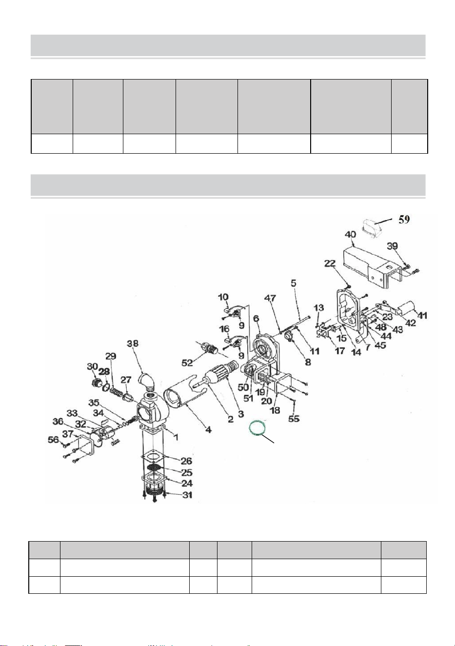
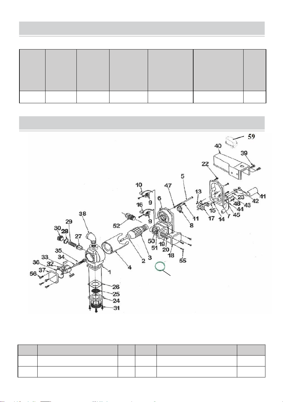
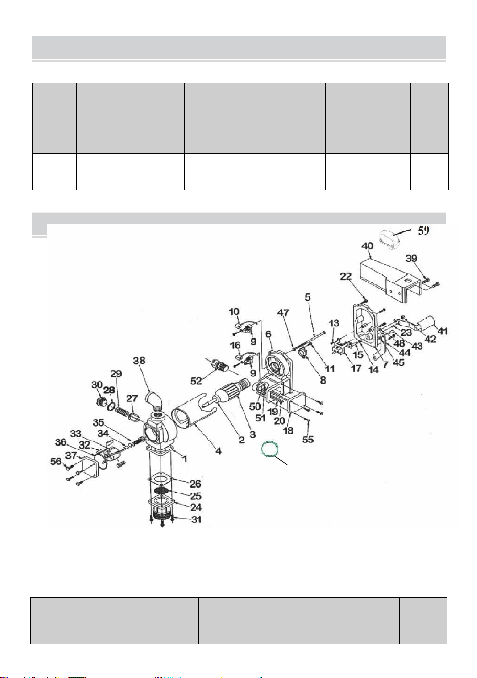
PARTS LIST
SECIFICATIONS
Model
Voltage
Input(W)
Flow Rate
(GPM)
Inlet pipe
specification
(inch)
Outlet pipe
specification
(inch)
G.W.
(kg)
KEX-20
DC12V
400
20
1
1
11.28
REF#
DESCRIPTION
OTY
REF#
DESCRIPTION
OTY
1
PUMPHOUSING
1
34
ROTOR KEY
1
2
BALL BEARING
2
35
ROTOR COVER
1
60

-
18
-
3
RMATUREASSEMBLY
1
36
ROTOR COVER GASKET
1
4
MOTOR
FRAME/MAGNETASSEMBLY
1
37
SEALASSEMBLY
1
5
1/4-2×5THRU-BOLT
2
38
STEEL ELBOW
1
6
MOTOR CASTING ASSEMBLY
1
39
5/16-18×3/4HHCS
1
7
SWITCH PLATE WITH BUS
HING
1
40
NOZZLE COVER
2
8
THERMAL PROTECTOR
1
41
SWITCH LEVER
1
9
BRUSH HOLDER ASSEMBLY
2
42
5/15×18LOVK NUT
1
10
NEGATIVE BRUSH
ASSEMBLY
1
43
#14×S/8DRVE SCREW
1
11
#8-32×1/2TORX
1
44
LOCKING LINK
1
12
-
45
1/4 SPRING WASHER
1
13
#8-32×3/8 TORX
2
46
ECT LOCK WASHER
1
14
5/16 SPRING WASHER
1
47
-
15
SWITCH SHAFTASSEMBLY
1
48
5/16 RETAINING RING
2
16
POSITIVEBRUSHASSEMBLY
1
49
GROUND WIRE
1
17
LINE SWITCH
1
50
-
18
JUNCTION BOX COVER
1
51
#832×3/8GROUND SCREW
1
19
NEGATIVE WIRE LEAD
1
52
CABLE CONNECTOR
1
20
POSITIVE WIRE LEAD
1
53
-
-
21
-
54
-
-
22
10-24×3/4 TORX
6
55
10-24×.50TORX
4
23
5/32×1/2PIN
1
56
1/4-20×.5HHCS
4
24
INLET FLANGE
1
57
-
-
25
SCREEN
1
58
-
-
26
INLET GASKET
1
59
OIL RECEIVING BOX
1
27
BYPASS VALVE
1
60
Ground Wire
1
28
BYASS VALVE GASKET
1
29
BYPASS SPRING
1
30
BYPASS CAP
1
31
1/4-20×3/4HHCS
1
32
VANE
4
33
ROTOR
5


-
20
-
Technique Soutien et Garantie électronique Certificat www.vevor.com/support
CARBURANT TRANSFERT POMPE
(
Simple
)
PROPRIÉTAIRES INSTALLATION,
OPÉRATION, ET SÉCURITÉ MANUEL
MODÈLE : KEX-20
Nous continuer à être engagé à fournir toi outils avec compétitif prix.
« Économisez la moitié », « Moitié prix » ou toute autre expression similaire utilisée par
nous ne représente qu'une estimation de économies toi pourrait avantage depuis achat
certain outils avec nous comparé à le majeurgrandes marques et ne vise pas
nécessairement à couvrir toutes les catégories d'outils que nous proposons. Vousnous vous
rappelons de bien vouloir vérifier attentivement lorsque vous passez une commande chez
nous si vous êtes en fait économiser la moitié en comparaison avec le haut majeur marques.

-
1
-
This is the original instruction, please read all manual instructions
carefully before operating. VEVOR reserves a clear interpretation of our
user manual. The appearance of the product shall be subject to the
product you received. Please forgive us that we won't inform you again if
there are any technology or software updates on our product.
FUEL TRANSFER PUMP
MODÈLE: KEX-20
Have product questions? Need technical support? Please feel free to
contact us:
Technical Support and E-Warranty Certificate
www.vevor.com/support
NEED HELP? CONTACT US!

-
2
-
SAFETY INFORMATION
WARNING! Electrical wiring should be performed ONLY by a
licensed electrician in compliance with local, state, and national
electrical code NEC/ANSI/ NFPA 70, NFPA 30, and NFPA 30A, as
appropriate to the intended use of the pump. Threaded rigid conduit,
sealed fittings, and conductor seal should be used where applicable.
The pump must be properly grounded. Improper installation or use of
this pump can result in serious bodily injury, or death!
AVERTISSEMENT! À assurer sûr et approprié opération de ton
équipement,il est essentiel de lire et de respecter tous les
avertissements de sécurité suivants et précautions. Une installation ou
une utilisation incorrecte de ce produit peut entraîner sérieux physique
blessure ou la mort!
NE JAMAIS fumer à proximité de la pompe, ni utiliser la pompe à
proximité de flammes nues quand pompage un liquide inflammable !
Feu peut résultat!
Un filtre doit être utilisé à la sortie de la pompe pour garantir
l'absence de corps étrangers. matériel est transféré à le carburant
réservoir.
Fileté tuyau articulations et relations doit être scellé avec le un
produit d'étanchéité ou un ruban d'étanchéité approprié pour
minimiser la possibilité de fuites.
Les réservoirs de stockage doivent être solidement ancré pour
éviter déplacement ou pourboire quand complet ou vide.
À minimiser statique électricité construire en haut, utiliser seulement
statique fil conducteur tuyau lors du pompage de liquides
inflammables et gardez la buse de remplissage en position contact
avec le récipient être rempli pendant le remplissage processus.
Le moteur de la pompe est équipé d'une protection contre les

-
3
-
surcharges thermiques ; sisurchauffé, le moteur s'arrêtera pour
éviter d'endommager le enroulements.

-
4
-
INSTALLATION
WARNING! This product shall not be used to transfer fluids into
any type of aircraft.
WARNING! This product is not suited for use with fluids intended
for human consumption or fluids containing water.
La pompe de transfert de carburant 20GMP est conçue pour être montée
sur un réservoir à patins à l'aide la bride d'entrée filetée fournie avec la
pompe. Votre pompe est équipée d'un vanne de dérivation intégrée pour
faire recirculer le fluide lorsque la pompe fonctionne avec le ajutage fermé.
WARNING! This product is not suited for use with fluids intended
for human consumption or fluids containing water.
CAUTION! Do not use additional check valves or foot valves
unless they have a proper pressure relief valve built into them. Note that
additional check valves will reduce rate of flow.

-
5
-
CAUTION! A pressure retaining fill cap can be used to reduce fuel
loss through evaporation, but note that it will reduce the flow rate.
CAUTION! Threaded pipe joints and connections must be sealed
with the appropriate sealant or sealant tape to prevent the possibility of
leaks.
WARNING! 20GMP fuel transfer pumps are designed for use with
stationary and mobile tank applications. While DC powered units are
excellent choice for mobile applications, anchoring the tank to which the
pump is mounted is paramount to ensure no movement in transit.
Failure to secure the tank to the vehicle can cause uncontrolled
movement, resulting in damage, injury, and potential fire.

-
6
-
Typique Déraper Réservoir Installation
Le pompe montures à le bonde de un déraper réservoir par chemin de le
entrée bride. Lele tube d'aspiration se visse dans le bas de la bride
d'admission et doit s'étendre jusqu'àune longueur qui le positionne à au
moins 3 pouces du fond du réservoir. Le patin réservoir devrait être équipé
avec un évent capuchon.
Matériels:
Tuyau d'aspiration télescopique de 1 po étendu sur une longueur qui
s'étendra jusqu'à à moins de 3 pouces du fond du réservoir lorsqu'il
est vissé dans l'adaptateur du réservoiravec l'adaptateur de réservoir
vissé dans la bride du réservoir (voir SKID TANK INSTALLATION
diagramme).
Fileté tuyau articulation scellant approprié pour application.

-
7
-
Installation Procédure:
4. Fil le 1” tuyau dans le réservoir adaptateur. Joint fils liquide serré
avecapproprié produit d'étanchéité. (Chiffre 1)
Typique Déraper Réservoir Installation (suite)
5. Visser la bride d'admission (avec tuyau d'aspiration) dans le
bouchon du réservoir ; scellerfils liquide serré avec approprié fil
scellant (Chiffre 2).

-
8
-
ELECTRICAL WIRING
6. Montez la pompe sur l'adaptateur en vous assurant que le joint et
l'écran sontinstallé comme montré. (Chiffre 3).
CAUTION! DC powered pumps are designed to operate on either
12 or 24 VDC (depending on model). Where applicable, use the
supplied battery cable to supply power to the pump from a 12 or 24
VDC battery. A 40 amp fuse (20 amp fuse on 24 VDC motors) should be
installed on the battery cable to protect the wire in case of electrical
short.

-
9
-
CAUTION! Voltage drop in wiring varies depending on the
distance from the battery to the pump and the gauge of the wire used. If
the distance is greater than 20’, refer to national, international, or local
electrical codes to ensure the wire is of the correct size for this
application.
Instructions Avant Procédure Avec Câblage CC
La pompe doit être reliée électriquement au réservoir d'alimentation ou au
châssis du véhicule. Pour relier électriquement la pompe, retirez la vis de
liaison verte située à côté couvercle de la boîte de jonction. Insérez cette
vis dans l'œillet du vert fourni collage fil assemblée et rattacher il en toute
sécurité à le pompe. Le autre finde le fil est à être dépouillé de isolation et
le nu fil en toute sécurité liéà le véhicule / bande-annonce cadre ou
déraper réservoir.
WARNING! Do not connect the positive or negative power to the
green screw or wire as this could cause a fire.
Câblage Instructions
7. Retirer pompes électrique jonction boîte couverture et redresser
le 2fils à rendre les extrémités des fils dénudés accessibles à
l'extérieur de la jonction boîte.
8. Vis meublé câble connecteur dans TNP* conduit ouverture dans
pompejonction boîte.
9. Bande 6 pouces de le extérieur revêtement depuis un fin de le

-
10
-
meublé

-
11
-
électrique câble être prudent pas à dommage le noir et rouge fil
isolation.
10. Desserrer câble connecteur noix et passer le dépouillé fin de le
meublécâble à travers le câble connecteur. Serrer le câble connecteur
noix.
11. Bande 1
⁄
2 pouce de le isolation
depuis le fin s de le rouge et noir
câbles . À l' aide des serre-fils fournis, connectez ces fils à la pompe
fils correspondant le couleurs. Être bien sûr Non nu fil est exposé.
12. Pliez les fils dans la boîte de jonction et remettez le couvercle en
place en vous assurant que le joint est en place. Assurez-vous que
toutes les vis sont bien en place afin qu'il n'y ait pas d'espace entre le
couverture et le jonction boîte.
Câblage À UN Véhicule Électrique Système
5. Faites passer les fils électriques à la source du système
d'alimentation du véhicule, soutenir les fils si nécessaire et les
protéger des objets tranchants bords, chaleur, et tout ce qui pourrait
dommage le fils.
6. Pour déterminer si le système électrique du véhicule est négatif (-) ou
positif (+) masse, vérifiez le marquage de la batterie du terminal qui
est câblé à le châssis du véhicule ou le bloc moteur. Le fil rouge de la
pompe connectez-vous à la borne positive de la batterie et le fil noir
de la pompe connecter à batterie négative poste.
7. Fixez une extrémité du porte-fusible à l’extrémité du fil non mis à la
terre. Faire un solide électrique connexion avec le autre fin de le
fusible titulairedu côté non mis à la terre de la batterie, aussi près que
possible de la batterie possible. Faire un solide électrique connexion à
le fondé côté de lebatterie avec le fil restant. La borne de la batterie
ou l'extrémité de la batterie câble est recommandé.
8. Vérifier tous relations à faire bien sûr ils sont connecté par
instructions et tous les codes électriques. Installez le fusible de 4 0
ampères (20 ampères fusible dans les installations 24 VDC) dans le
porte-fusible. L'installation est maintenantcomplet.

-
12
-
WARNING! Do not attempt to power the pump from vehicle wiring
smaller than 12 gage such as the cigarette lighter wire because these
thin wires could overheat and cause a fire.
DC Câblage (suite)
Pour Déraper Monté Chars
4. Faites passer les fils électriques à la source d'alimentation, en
soutenant les fils commenécessaires et les protéger des bords
tranchants, de la chaleur et de tout que pourrait dommage le fils.
5. Fixez une extrémité du porte-fusible au fil rouge de la pompe, le
plus près possible la batterie/source d'alimentation que possible.
Faites un circuit électrique solide connexion à la borne positive de la
source d'alimentation avec l'autreextrémité du porte-fusible.
Établissez une connexion solide avec la pompe noire fil à le négatif
Terminal de le pouvoir source.
6. Vérifiez toutes les connexions pour vous assurer qu'elles sont
connectées par instructions et tous les codes électriques. Installez le
fusible de 4 0 ampères (20 ampères fusible dans 24 VDC
installations) dans le fusible titulaire. Le installation est maintenant
complet.

-
13
-
DC Câblage Diagramme

-
14
-
WARNING! Always keep the nozzle in contact with the container
being filled during the filling process to minimize the possibility of static
electricity build up.
OPERATING INSTRUCTIONS
4.
Si donc équipé, réinitialiser mètre à « 0 » (faire pas réinitialiser alors
que dans utiliser comme ça volontécause dommage à le mètre).
5.Retirer distribution ajutage depuis ajutage botte.
6.Déplacez le levier de l’interrupteur sur la position « ON » pour alimenter
la pompe (figure 1).4.Insérer le distribution buse dans le récipient à être
rempli.
8.Actionnez la buse pour distribuer le liquide ; relâchez la buse lorsque
le liquide souhaité est distribué.montant de le fluide a a été dispensé.
“ON”positiong
Figure 1

-
15
-
-
16
-
9.Se déplacer changer levier à le "DÉSACTIVÉ" position (Chiffre 2) à tourner
désactivé le pompe.
10. Retirer le distribution ajutage depuis le récipient être rempli et
magasin ildans le soufflet de buse.
Cadenassage
Ton pompe ajutage peut être cadenassuré à le pompe pour ajouté sécurité.
Avecle pompe tourné désactivé, et le ajutage dans le stocké position, un
cadenas peut êtreinséré à travers le verrouillage lien et le poignée de buse.
Le lien de verrouillage est situé sur le côté buse de la pompe et peut
êtrepivoté dans position à travail avec un variété de buses ( Figure 3 ).
“OFF”positiong
Figure 2
locking Link
Figure 3

-
17
-

-
18
-
WARNING! DO NOT open or attempt to repair the motor on your
pump. Return it to the place of purchase for service. Opening the motor
case can compromise the integrity of the Explosion Proof construction
and will void any existing warranty and certification.
WARNING! Be certain all power to the pump is disconnected prior
to performing any service or maintenance.
TROUBLESHOOTING
Le guide de dépannage suivant est fourni pour offrir un diagnostic de base
assistance en cas de service anormal de votre 20GMPcarburant transfert
produit.

-
19
-
Symptôme
Cause
Guér
ir
La pompe
ne
fonctionne
pasprime.
1. Conduite d'aspiration
problème.
Vérifier pour fuites ou obstructions dans succion
doubler.
2. By-pass soupape ouvrir.
Retirer et inspecter soupape; doit se déplacer
librement & être
gratuit de débris.
3. Aubes collage.
Vérifier aubes et machines à sous pour entailles,
bavures et porter.
4. Excessif rotor ou
girouette
porter.
Inspecter rotor & aubes pour excessif porter ou
dommage; remplacer si nécessaire.
5. Vapeur Verrouillage.
Réduisez la distance verticale et horizontale
depompe à liquide; retirer automatique
ajutage.
Faible capacité.
1. Excessif saleté dans
écran.
Retirer et faire le ménage écran.
2. Conduite d'aspiration
problème.
Vérifiez la conduite d'aspiration pour détecter les
fuites ou les restrictions ; cela peutêtre aussi
petit, aussi long ou pas hermétique.
3. By-pass soupape collage.
Retirer et inspecter soupape; doit se déplacer
librement & être
gratuit de débris.
4. Sortie bloqué.
Vérifier pompe sortie, tuyau, buse et filtre pour
obstruction.
5. Aubes collage.
Vérifier aubes et machines à sous pour porter.
6. Excessif rotor ou
girouetteporter.
Inspecter rotor & aubes pour excessif
porter oudommage; remplacer si
nécessaire.
7. Tuyau ou ajutage
dommage.
Remplacer tuyau ou ajutage.
8. Branché filtre.
Remplacer filtre.
9. Faible teneur en liquide
niveau.
Remplir réservoir.
La pompe
1. Incorrect tension.
Vérifier entrant tension de ligne alors que la pompe
est
en cours d'exécution.
2. Aubes collage.
Inspecter aubes et machines à sous pour entailles,
bavures et porter.

-
20
-
fonctionne
lentement.
3. Câblage problème.
Vérifier pour lâche relations.
4. Moteur problème.
Retour à lieu de achat.

-
21
-
TROUBLESHOOTING (CONT’D)
Le moteur cale /
fusiblecoups ou
thermiques
voyages
protecteurs à
plusieurs
reprises.
1. By-pass soupape collage.
Retirer et inspecter soupape; doit se déplacer
librement
& être libre de débris.
2. Faible tension.
Vérifier entrant tension de ligne pendant que la
pompe est
en cours d'exécution.
3. Excessif rotor ou usure des
aubes.
Vérifier rotor & aubes pour excessif porter ou
dommage.
4. Débris dans pompe cavité.
Faire le ménage débris depuis pompe cavité.
Moteur
surchauffe
.
1. Pompage haut viscosité fluides.
Ces fluides peut seulement être pompé pour
court
périodes de temps (moins de 30 minutes
de servicefaire du vélo).
2. Bouché écran.
Retirer et faire le ménage écran.
3. Limité succion tuyau.
Retirer et faire le ménage tuyau.
4. Moteur échec.
Retour à lieu de achat.
5. Pompe blocage du rotor.
Faire le ménage et vérifier pompe rotor et
aubes.
Moteur
Inopérant.
1. Non pouvoir.
Vérifier entrant pouvoir.
2. Changer échec.
Remplacer changer .
3. Moteur échec.
Retour à lieu de achat.
4. Thermique protecteur échec.
Retour à lieu de achat.
5. Incorrect/lâche câblage.
Vérifier câblage.
Fluide fuite.
1. Joint torique défectueux joint.
Vérifier tous joint torique joints.
2. Sale arbre joint.
Faire le ménage joint & joint cavité.
3. Arbre défectueux joint.
Remplacer joint.
4. Incompatible fluide.
Référer mouillé parties liste à fluide fabricant.
5. Lâche attaches.
Serrer attaches.
Pompe bourdonne
mais
volonté pas
fonctionner.
1. Moteur échec.
Retour à lieu de achat.
2. Cassé rotor clé.
Retirer tous débris & remplacer clé.
-
22
-
PARTS LIST
SECIFICATIONS
Modèl
e
Tension
Entrée
(W)
Débit
(GPM)
Tuyau
d'admission
spécification
( pouce )
Tuyau de
sortie
spécification
( pouce )
GW
(kg)
KEX-20
12 V CC
400
20
1
1
11.28
RÉF#
DESCRIPTION
OTY
RÉF#
DESCRIPTION
OTY
1
BOÎTIER DE POMPE
1
34
ROTOR CLÉ
1
2
BALLE PALIER
2
35
ROTOR COUVERTURE
1
60

-
23
-
3
ASSEMBLAGE MATURE
1
36
ROTOR COUVERTURE JOINT
1
4
MOTEUR
ENSEMBLE CADRE/AIMANT
1
37
ENSEMBLE DE JOINTS
1
5
1/4-2×5 BOULON
TRAVERSANT
2
38
ACIER COUDE
1
6
MOTEUR FONDERIE
ASSEMBLÉE
1
39
5/16-18×3/4HHCS
1
7
CHANGER PLAQUE AVEC
BUS HING
1
40
AJUTAGE COUVERTURE
2
8
THERMIQUE PROTECTEUR
1
41
CHANGER LEVIER
1
9
BROSSE TITULAIRE
ASSEMBLÉE
2
42
5/15×18LOVK NOIX
1
10
NÉGATIF BROSSE
ASSEMBLÉE
1
43
#14×S/8DRVE VIS
1
11
Clé Torx n° 8-32×1/2
1
44
VERROUILLAGE LIEN
1
12
-
45
1/4 PRINTEMPS RONDELLE
1
13
#8-32×3/8 TORX
2
46
Électronique VERROUILLAGE
RONDELLE
1
14
5/16 PRINTEMPS RONDELLE
1
47
-
15
CHANGER ASSEMBLAGE DE
L'ARBRE
1
48
5/16 RETENIR ANNEAU
2
16
ASSEMBLAGE DE BROSSES
POSITIVES
1
49
SOL FIL
1
17
DOUBLER CHANGER
1
50
-
18
JONCTION BOÎTE
COUVERTURE
1
51
#832×3/8TERRAIN VIS
1
19
NÉGATIF FIL PLOMB
1
52
CÂBLE CONNECTEUR
1
20
POSITIF FIL PLOMB
1
53
-
-
21
-
54
-
-
22
10-24×3/4 TORX
6
55
Clé Torx 10-24×.50
4
23
5/32×1/2PIN
1
56
1/4-20×.5HHCS
4
24
Entrée BRIDE
1
57
-
-
25
ÉCRAN
1
58
-
-
26
Entrée JOINT
1
59
HUILE RÉCEPTION BOÎTE
1
27
BY-PASS SOUPAPE
1
60
Sol Fil
1
28
PARASS SOUPAPE JOINT
1
29
BY-PASS PRINTEMPS
1
30
BY-PASS CAPUCHON
1
31
1/4-20×3/4HHCS
1

-
24
-
32
GIROUETTE
4
33
ROTOR
5


-
26
-
Technisch Unterstützung Und E-Garantie Zertifikat www.vevor.com/support
KRAFTSTOFF ÜBERWEISEN PUMPE
( Einzeln )
Eigentümer INSTALLATION,
BETRIEB, UND SICHERHEIT HANDBUCH
MODELL: KEX-20
Wir weitermachen Zu Sei engagiert Zu bieten Du Werkzeuge mit wettbewerbsfähig Preis.
"Sparen Sie die Hälfte", "Halber Preis" oder andere ähnliche Ausdrücke, die wir verwenden,
stellen nur eine schätzen von Ersparnisse Du könnte Nutzen aus Kauf bestimmt Werkzeuge
mit uns verglichen Zu Die wesentlichTop-Marken und bedeutet nicht notwendigerweise, alle
von uns angebotenen Werkzeugkategorien abzudecken. SieWir möchten Sie bitten, bei der
Bestellung sorgfältig zu prüfen, ob Sie Genau genommen die Hälfte sparen im Vergleich mit
dem Spitze wesentlich Marken.

-
1
-
This is the original instruction, please read all manual instructions
carefully before operating. VEVOR reserves a clear interpretation of our
user manual. The appearance of the product shall be subject to the
product you received. Please forgive us that we won't inform you again if
there are any technology or software updates on our product.
FUEL TRANSFER PUMP
MODELL: KEX-20
Have product questions? Need technical support? Please feel free to
contact us:
Technical Support and E-Warranty Certificate
www.vevor.com/support
NEED HELP? CONTACT US!

-
2
-
SAFETY INFORMATION
WARNING! Electrical wiring should be performed ONLY by a
licensed electrician in compliance with local, state, and national
electrical code NEC/ANSI/ NFPA 70, NFPA 30, and NFPA 30A, as
appropriate to the intended use of the pump. Threaded rigid conduit,
sealed fittings, and conductor seal should be used where applicable.
The pump must be properly grounded. Improper installation or use of
this pump can result in serious bodily injury, or death!
WARNUNG! Zu sicherstellen sicher und richtig Betrieb von dein
Ausrüstung,Es ist wichtig, alle folgenden Sicherheitshinweise zu lesen
und zu befolgen und Vorsichtsmaßnahmen. Eine unsachgemäße
Installation oder Verwendung dieses Produkts kann zu ernst körperlich
Verletzung oder Tod!
Rauchen Sie NIEMALS in der Nähe der Pumpe und verwenden Sie
die Pumpe NIEMALS in der Nähe von offenem Feuer. Wann
Pumpen A brennbare Flüssigkeit! Feuer dürfen Ergebnis!
Am Pumpenauslass sollte ein Filter angebracht werden, um
sicherzustellen, dass keine Fremdkörper Material Ist übertragen Zu
Die Kraftstoff Tank.
Gewinde Rohr Gelenke Und Anschlüsse muss Sei versiegelt mit Die
geeignetes Dichtungsmittel oder Dichtungsband, um die Möglichkeit
von Lecks.
Lagertanks müssen sicher verankert sein, um zu verhindern
Verschiebung oder Kippen Wann voll oder leer.
Zu minimieren statisch Strom bauen hoch, verwenden nur statisch
Draht leitfähigSchlauch beim Pumpen von brennbaren Flüssigkeiten,
und halten Sie die Fülldüse in Kontakt mit Die Container Sein gefüllt
während Die Füllung Verfahren.
Der Pumpenmotor ist mit einem thermischen

-
3
-
Überlastungsschutz ausgestattet.überhitzt, schaltet der Motor
ab, um eine Beschädigung des Wicklungen.

-
4
-
INSTALLATION
WARNING! This product shall not be used to transfer fluids into
any type of aircraft.
WARNING! This product is not suited for use with fluids intended
for human consumption or fluids containing water.
Die Kraftstoffpumpe 20GMP ist für die Montage auf einem Skid-Tank
konzipiert.der mit der Pumpe gelieferte Gewindeflansch am Einlass. Ihre
Pumpe verfügt über einen integriertes Bypassventil zur Rückführung der
Flüssigkeit bei Pumpenbetrieb mit Die Düse geschlossen.
WARNING! This product is not suited for use with fluids intended
for human consumption or fluids containing water.
CAUTION! Do not use additional check valves or foot valves
unless they have a proper pressure relief valve built into them. Note that
additional check valves will reduce rate of flow.

-
5
-
CAUTION! A pressure retaining fill cap can be used to reduce fuel
loss through evaporation, but note that it will reduce the flow rate.
CAUTION! Threaded pipe joints and connections must be sealed
with the appropriate sealant or sealant tape to prevent the possibility of
leaks.
WARNING! 20GMP fuel transfer pumps are designed for use with
stationary and mobile tank applications. While DC powered units are
excellent choice for mobile applications, anchoring the tank to which the
pump is mounted is paramount to ensure no movement in transit.
Failure to secure the tank to the vehicle can cause uncontrolled
movement, resulting in damage, injury, and potential fire.
-
6
-
Typisch Schleudern Tank Installation
Der Pumpe Reittiere Zu Die Spund von A Schleudern Tank von Weg von
Die Einlass Flansch. DerDas Saugrohr wird in die Unterseite des
Einlassflansches eingeschraubt und muss bis zumeine Länge, die
mindestens 3 Zoll vom Boden des Tanks entfernt ist. Der Schlitten Tank
sollen ausgerüstet sein mit einem Entlüftung Kappe.
Materialien:
1" Teleskop-Saugrohr, ausgefahren auf eine Länge von bis zu
innerhalb von 3 Zoll vom Boden des Tanks, wenn in den Tankadapter
geschraubtmit dem in den Tankflansch eingeschraubten Tankadapter
(siehe SKID TANK INSTALLATION Diagramm).
Gewinde Rohr gemeinsam Dichtungsmittel geeignet für Anwendung.

-
7
-
Installation Verfahren:
7. Faden Die 1” Rohr hinein Die Tank Adapter. Siegel Fäden flüssig
eng mitgeeignet Dichtungsmittel. (Figur 1)
Typisch Schleudern Tank Installation (Fortsetzung)
8. Den Zulaufflansch (mit Saugrohr) in den Tankstopfen
einschrauben, abdichtenFäden flüssig eng mit geeignet Faden
Dichtungsmittel (Figur 2).

-
8
-
ELECTRICAL WIRING
9. Montieren Sie die Pumpe am Adapter. Stellen Sie sicher, dass
Dichtung und Siebinstalliert als gezeigt. (Figur 3).
CAUTION! DC powered pumps are designed to operate on either
12 or 24 VDC (depending on model). Where applicable, use the
supplied battery cable to supply power to the pump from a 12 or 24
VDC battery. A 40 amp fuse (20 amp fuse on 24 VDC motors) should be
installed on the battery cable to protect the wire in case of electrical
short.

-
9
-
CAUTION! Voltage drop in wiring varies depending on the
distance from the battery to the pump and the gauge of the wire used. If
the distance is greater than 20’, refer to national, international, or local
electrical codes to ensure the wire is of the correct size for this
application.
Anweisungen Vor Vorgehensweise Mit DC-Verkabelung
Die Pumpe muss elektrisch mit dem Vorratstank oder dem
Fahrzeugrahmen verbunden sein. Um die Pumpe elektrisch zu verbinden,
entfernen Sie die grüne Verbindungsschraube neben Abdeckung des
Anschlusskastens. Führen Sie diese Schraube durch die Öse des
mitgelieferten grünen Verklebung Draht Montage Und wieder befestigen
Es sicher Zu Die Pumpe. Der andere Endevon Die Draht Ist Zu Sei
abgestreift von Isolierung Und Die nackt Draht sicher gebundenZu Die
Fahrzeug / Anhänger rahmen oder Schleudern Tank.
WARNING! Do not connect the positive or negative power to the
green screw or wire as this could cause a fire.
Verdrahtung Anweisungen
13. Entfernen Pumps elektrisch Kreuzung Kasten Abdeckung Und
begradigen Die 2Drähte Zu die abisolierten Kabelenden
außerhalb des Kreuzung Kasten.
14. Schrauben möbliert Kabel Anschluss hinein NVV* Leitung Öffnung
In PumpeKreuzung Kasten.

-
10
-
15. Streifen 6 Zoll von Die äußere Abdeckung aus eins Ende von Die
möbliert

-
11
-
elektrisch Kabel Sein vorsichtig nicht Zu Schaden Die Schwarz Und
Rot DrahtIsolierung.
16. Lösen Kabel Anschluss Nuss Und passieren Die abgestreift Ende von
Die möbliert Kabel durch Die Kabel Anschluss. Anziehen Die Kabel
Anschluss Nuss.
17. Streifen 1
⁄
2 ich nc h von Die Isolierung
aus Die Ende von Die Rot Und
Schwarz Kabeldrähte . Verbinden Sie diese Drähte mit den
mitgelieferten Kabelverbindern mit der Pumpe Drähte passend Die
Farben. Sei Sicher NEIN nackt Draht Ist ausgesetzt.
18. Falten Sie die Drähte in die Anschlussdose und setzen Sie die
Abdeckung wieder auf. Stellen Sie sicher, dass die Dichtung ist
vorhanden. Stellen Sie sicher, dass alle Schrauben richtig sitzen, so
dass kein Zwischenraum vorhanden ist zwischen Die Abdeckung und
die Kreuzung Kasten.
Verdrahtung Zu A Fahrzeug Elektrisch System
9. Führen Sie die elektrischen Leitungen zur Quelle des
Fahrzeugstromversorgungssystems, Stützen Sie die Drähte bei
Bedarf und schützen Sie sie vor scharfen Kanten, Hitze, Und alles,
was könnte Schaden Die Drähte.
10. Um festzustellen, ob das elektrische System des Fahrzeugs negativ (-)
oder positiv ist (+) Masse, überprüfen Sie die Batteriemarkierung des
Anschlusses, der mit dem am Fahrzeugrahmen oder am Motorblock.
Das rote Kabel von der Pumpe wird an den Pluspol der Batterie
anschließen und das schwarze Kabel von der Pumpe verbinden Zu
negativer Batteriestand Post.
11. Befestigen Sie ein Ende des Sicherungshalters am Ende des nicht
geerdeten Kabels. Machen A solide elektrisch Verbindung mit Die
andere Ende von Die Sicherung Halteran die nicht geerdete Seite der
Batterie, so nah an der Batterie wie möglich. Machen A solide
elektrisch Verbindung Zu Die geerdet Seite von Die Batterie mit dem
restlichen Kabel. Der Batteriepol oder das Ende des Batterie Kabel Ist
empfohlen.
12. Überprüfen alle Anschlüsse Zu machen Sicher Sie Sind verbunden

-
12
-
pro Anweisungen und alle elektrischen Vorschriften. Installieren Sie
die 4 0 Ampere Sicherung (20 Ampere Sicherung in 24 VDC-
Installationen) im Sicherungshalter. Die Installation ist nunvollständig.

-
13
-
WARNING! Do not attempt to power the pump from vehicle wiring
smaller than 12 gage such as the cigarette lighter wire because these
thin wires could overheat and cause a fire.
Gleichstrom Verdrahtung (Fortsetzung)
Für Schleudern Montage Panzer
7. Führen Sie die elektrischen Leitungen zur Stromquelle und stützen
Sie sie dabei so ab,notwendig und schützt sie vor scharfen Kanten,
Hitze und allem Das könnte Schaden Die Drähte.
8. Befestigen Sie ein Ende des Sicherungshalters am roten
Pumpenkabel, so nah wie möglich von der Batterie/Stromquelle
wie möglich. Sorgen Sie für eine solide elektrische Anschluss an
den Pluspol der Stromquelle mit dem anderenEnde des
Sicherungshalters. Stellen Sie eine feste Verbindung mit dem
schwarzen Pumpenkopf her. Draht Zu Die Negativ Terminal von Die
Leistung Quelle.
9. Überprüfen Sie alle Verbindungen, um sicherzustellen, dass sie
ordnungsgemäß angeschlossen sind. Anweisungen und alle
elektrischen Vorschriften. Installieren Sie die 4 0 Ampere Sicherung
(20 Ampere Sicherung In 24 VDC Installationen) In Die Sicherung
Halter. Der Installation Ist Jetztvollständig.
-
14
-

-
15
-
Gleichstrom Verdrahtung Diagramm

-
16
-
WARNING! Always keep the nozzle in contact with the container
being filled during the filling process to minimize the possibility of static
electricity build up.
OPERATING INSTRUCTIONS
7.
Wenn Also ausgestattet, zurücksetzen Meter Zu „0“ (Tun nicht
zurücksetzen während In verwenden wie dies WilleUrsache Schaden
Zu Die Meter).
8.
Entfernen Dosierung Düse aus Düse Stiefel.
9.
Bewegen Sie den Schalterhebel in die Position „ON“, um die Pumpe
einzuschalten (Abbildung 1).4.Einfügen Die Dosierung Düse in Die
Container Zu Sei gefüllt.
11.
Betätigen Sie die Düse, um Flüssigkeit abzugeben; lassen Sie die
Düse los, wenn die gewünschteMenge von Flüssigkeit hat gewesen
abgegeben.
“ON”positiong
Figure 1

-
17
-

-
18
-
12. Bewegen schalten Hebel Zu Die "AUS" Position (Figur 2) Zu drehen
aus Die Pumpe.
13. Entfernen Die Dosierung Düse aus Die Container Sein gefüllt Und
speichern EsIn Die Düsenstiefel.
Vorhängeschloss
Dein Pumpe Düse dürfen Sei mit Vorhängeschloss Zu Die Pumpe für
hinzugefügt Sicherheit. Mit Die Pumpe gedreht aus, Und Die Düse In Die
gelagert Position, A Vorhängeschloss dürfen Sei eingefügt durch die
Verriegelung Link Und Die Düsengriff.
Der Verriegelungshebel befindet sich auf der Düsenseite der Pumpe
und kannschwenkbar hinein Position Zu arbeiten mit A Vielzahl von
Düsen ( Abbildung 3 ).
“OFF”positiong
Figure 2
locking Link
Figure 3

-
19
-

-
20
-
WARNING! DO NOT open or attempt to repair the motor on your
pump. Return it to the place of purchase for service. Opening the motor
case can compromise the integrity of the Explosion Proof construction
and will void any existing warranty and certification.
WARNING! Be certain all power to the pump is disconnected prior
to performing any service or maintenance.
TROUBLESHOOTING
Der folgende Leitfaden zur Fehlerbehebung bietet eine grundlegende
Diagnose Hilfe bei Störungen im Service Ihres 20GMPKraftstoff
überweisen Produkt.

-
21
-
Symptom
Ursac
he
Heilu
ng
Pumpe
funktioniert
nicht
Primzahl.
1. Saugleitung Problem.
Überprüfen für Lecks oder Hindernisse In
Absaugung Linie.
2. Bypass Ventil offen.
Entfernen Und überprüfen Ventil; muss bewegen
frei und Sei
frei von Trümmer.
3. Leitschaufeln kleben.
Überprüfen Schaufeln Und Spielautomaten für
Kerben, Grate Und tragen.
4. Übermäßig Rotor oder
Schaufel
tragen.
Überprüfen Rotor und Schaufeln für übermäßig
tragen oder
Schaden; ersetzen Wenn notwendig.
5. Dampf Sperren.
Reduzieren Sie den vertikalen und
horizontalen Abstand vonPumpe Zu flüssig;
entfernen automatisch Düse.
Niedrig
Kapazität.
1. Übermäßig Schmutz In
Bildschirm.
Entfernen Und sauber Bildschirm.
2. Saugleitung Problem.
Überprüfen Sie die Saugleitung auf
Undichtigkeiten oder Verstopfungen.Sei zu klein,
zu lang oder nicht luftdicht.
3. Bypass Ventil kleben.
Entfernen Und überprüfen Ventil; muss bewegen
frei und Sei
frei von Trümmer.
4. Auslauf blockiert.
Überprüfen Pumpe Steckdose, Schlauch, Düse &
Filter für
Blockierung.
5. Leitschaufeln kleben.
Überprüfen Schaufeln Und Spielautomaten für
tragen.
6. Übermäßig Rotor oder
Schaufeltragen.
Überprüfen Rotor und Schaufeln für
übermäßig tragen oderSchaden; ersetzen
Wenn notwendig.
7. Schlauch oder Düse
Schaden.
Ersetzen Schlauch oder Düse.
8. Eingesteckt Filter.
Ersetzen Filter.
9. Niedriger
Flüssigkeitsstand Ebene.
Füllen Tank.
Pumpe
1. Falsch Stromspannung.
Überprüfen eingehend Netzspannung während
Pumpe ist
läuft.
2. Leitschaufeln kleben.
Überprüfen Schaufeln Und Spielautomaten für
Kerben, Grate Und tragen.

-
22
-
läuft
langsam.
3. Verdrahtung Problem.
Überprüfen für lose Verbindungen.
4. Motor Problem.
Zurückkehren Zu Ort von kaufen.

-
23
-
TROUBLESHOOTING (CONT’D)
Motor blockiert /
Sicherung
Schläge oder
thermische
Beschützerreisen
wiederholt.
1. Bypass Ventil kleben.
Entfernen Und überprüfen Ventil; muss
bewegen frei
und Sei frei von Trümmer.
2. Niedrig Stromspannung.
Überprüfen eingehend Netzspannung während
der Pumpe Ist
läuft.
3. Übermäßig Rotor oder
Schaufelverschleiß.
Überprüfen Rotor und Schaufeln für
übermäßig tragen oder
Schaden.
4. Trümmer In Pumpe Hohlraum.
Sauber Trümmer aus Pumpe Hohlraum.
Motor
überhitzt.
1. Pumpen hoch Viskosität
Flüssigkeiten.
Diese Flüssigkeiten dürfen nur Sei gepumpt
für kurz
Zeiträume (weniger als 30 Minuten Dienst
Zyklus).
2. Verstopft Bildschirm.
Entfernen Und sauber Bildschirm.
3. Eingeschränkt Absaugung
Rohr.
Entfernen Und sauber Rohr.
4. Motor Versagen.
Zurückkehren Zu Ort von kaufen.
5. Pumpe Rotorblockierung.
Sauber Und überprüfen Pumpe Rotor und
Leitschaufeln.
Motor Nicht
funktionsfä
hig.
1. NEIN Leistung.
Überprüfen eingehend Leistung.
2. Schalten Versagen.
Ersetzen schalten .
3. Motor Versagen.
Zurückkehren Zu Ort von kaufen.
4. Thermal Schutz Versagen.
Zurückkehren Zu Ort von kaufen.
5. Falsch/locker Verdrahtung.
Überprüfen Verdrahtung.
Flüssigkeit
Leckage.
1. Schlechter O-Ring Dichtung.
Überprüfen alle O-Ring Dichtungen.
2. Schmutzig Welle Siegel.
Sauber Siegel und Siegel Hohlraum.
3. Schlechter Schaft Siegel.
Ersetzen Siegel.
4. Unvereinbar Flüssigkeit.
Verweisen benetzt Teile Liste Zu Flüssigkeit
Hersteller.
5. Lose Befestigungselemente.
Anziehen Befestigungselemente.
Pumpe summt
Aber
Wille nicht
arbeiten.
1. Motor Versagen.
Zurückkehren Zu Ort von kaufen.
2. Gebrochen Rotor Schlüssel.
Entfernen alle Trümmer und ersetzen
Schlüssel.
-
24
-
PARTS LIST
SECIFICATIONS
Modell
Stroms
pannun
g
Leistung
(W)
Durchflus
srate
(GPM)
Zulaufrohr
Spezifikation
( Zoll )
Auslassroh
r
Spezifikation
( Zoll )
GW
(kg)
KEX-20
Gleichst
rom 12
V
400
20
1
1
11.28
Refer
enzn
umm
er
BESCHREIBUNG
OTY
Refere
nznum
mer
BESCHREIBUNG
OTY
60

-
25
-
1
PUMPENGEHÄUSE
1
34
ROTOR SCHLÜSSEL
1
2
BALL LAGER
2
35
ROTOR ABDECKUNG
1

-
26
-
3
RMATUREASSEMBLY
1
36
ROTOR ABDECKUNG
DICHTUNG
1
4
MOTOR
RAHMEN/MAGNETMONTAGE
1
37
DICHTUNGSMONTAGE
1
5
1/4-2×5
DURCHGANGSSCHRAUBE
2
38
STAHL ELLBOGEN
1
6
MOTOR Besetzung MONTAGE
1
39
5/16-18×3/4HHCS
1
7
SCHALTEN PLATTE MIT BUS
HING
1
40
DÜSE ABDECKUNG
2
8
THERMAL SCHUTZ
1
41
SCHALTEN HEBEL
1
9
BÜRSTE HALTER MONTAGE
2
42
5/15×18LOVK NUSS
1
10
NEGATIV BÜRSTE MONTAGE
1
43
#14×S/8ANTRIEB
SCHRAUBEN
1
11
#8-32×1/2TORX
1
44
VERRIEGELUNG LINK
1
12
-
45
1/4 FRÜHLING
WASCHMASCHINE
1
13
#8-32×3/8 TORX
2
46
Elektrokrampftherapie
SPERREN WASCHMASCHINE
1
14
5/16 FRÜHLING
WASCHMASCHINE
1
47
-
15
SCHALTEN
WELLENMONTAGE
1
48
5/16 Beibehaltung RING
2
16
Positive Bürsteneinheit
1
49
BODEN DRAHT
1
17
LINIE SCHALTEN
1
50
-
18
KREUZUNG KASTEN
ABDECKUNG
1
51
#832×3/8BODEN
SCHRAUBEN
1
19
NEGATIV DRAHT FÜHREN
1
52
KABEL ANSCHLUSS
1
20
POSITIV DRAHT FÜHREN
1
53
-
-
21
-
54
-
-
22
10-24×3/4 TORX
6
55
10-24×.50TORX
4
23
5/32×1/2PIN
1
56
1/4-20×.5HHCS
4
24
EINLASS FLANSCH
1
57
-
-
25
BILDSCHIRM
1
58
-
-
26
EINLASS DICHTUNG
1
59
ÖL EMPFANG KASTEN
1
27
BYPASS VENTIL
1
60
Boden Draht
1
28
BYASS VENTIL DICHTUNG
1
29
BYPASS FRÜHLING
1
30
BYPASS KAPPE
1
31
1/4-20×3/4HHCS
1

-
27
-
32
SCHAUFEL
4
33
ROTOR
5


-
29
-
Tecnico Supporto E Garanzia elettronica Certificato www.vevor.com/support
CARBURANTE TRASFERIRE POMPA
( Singola )
PROPRIETARI INSTALLAZIONE,
OPERAZIONE, E SICUREZZA MANUALE
MODELLO: KEX-20
Noi continuare A Essere impegnato A fornire Voi utensili con competitivo prezzo.
"Risparmia la metà", "Metà prezzo" o qualsiasi altra espressione simile da noi utilizzata
rappresenta solo un stima Di risparmio Voi Potrebbe beneficio da acquisto certo utensili con
noi confrontato A IL maggioremarchi top e non significa necessariamente coprire tutte le
categorie di strumenti da noi offerti.ti ricordiamo cortesemente di verificare attentamente
quando effettui un ordine con noi se sei In realtà risparmiando la metà in confronto con il
superiore maggiore marchi.

-
1
-
This is the original instruction, please read all manual instructions
carefully before operating. VEVOR reserves a clear interpretation of our
user manual. The appearance of the product shall be subject to the
product you received. Please forgive us that we won't inform you again if
there are any technology or software updates on our product.
FUEL TRANSFER PUMP
MODELLO: Il KEX-20
Have product questions? Need technical support? Please feel free to
contact us:
Technical Support and E-Warranty Certificate
www.vevor.com/support
NEED HELP? CONTACT US!

-
2
-
SAFETY INFORMATION
WARNING! Electrical wiring should be performed ONLY by a
licensed electrician in compliance with local, state, and national
electrical code NEC/ANSI/ NFPA 70, NFPA 30, and NFPA 30A, as
appropriate to the intended use of the pump. Threaded rigid conduit,
sealed fittings, and conductor seal should be used where applicable.
The pump must be properly grounded. Improper installation or use of
this pump can result in serious bodily injury, or death!
AVVERTIMENTO! A garantire sicuro e proprio operazione Di tuo
attrezzatura,è fondamentale leggere e rispettare tutte le seguenti
avvertenze di sicurezza e precauzioni. L'installazione o l'uso improprio di
questo prodotto può causare serio corporale infortunio O morte!
NON fumare MAI vicino alla pompa o utilizzare la pompa vicino a
fiamme libere Quando pompaggio UN liquido infiammabile! Fuoco
Potere risultato!
Si consiglia di utilizzare un filtro sull'uscita della pompa per garantire
che non vi siano corpi estranei. materiale È trasferito A IL
carburante cisterna.
Filettato tubo giunti E connessioni dovere Essere sigillato con IL
sigillante o nastro sigillante appropriato per ridurre al minimo la
possibilità di perdite.
I serbatoi di stoccaggio devono essere saldamente ancorato per
prevenire spostamento O mancia Quando pieno o vuoto.
A minimizzare statico elettricità costruire su, utilizzo soltanto statico
filo conduttivotubo flessibile quando si pompano fluidi infiammabili e
tenere l'ugello di riempimento in contatto con IL contenitore essendo
riempito durante IL riempimento processo.
Il motore della pompa è dotato di protezione da sovraccarico
termico; sesurriscaldato, il motore si spegnerà per evitare danni

-
3
-
al avvolgimenti.

-
4
-
INSTALLATION
WARNING! This product shall not be used to transfer fluids into
any type of aircraft.
WARNING! This product is not suited for use with fluids intended
for human consumption or fluids containing water.
La pompa di trasferimento del carburante 20GMP è progettata per essere
montata su un serbatoio skid utilizzando la flangia di ingresso filettata
fornita con la pompa. La pompa è dotata di un valvola di bypass integrale
per ricircolare il fluido quando la pompa è in funzione con IL ugello Chiuso.
WARNING! This product is not suited for use with fluids intended
for human consumption or fluids containing water.
CAUTION! Do not use additional check valves or foot valves
unless they have a proper pressure relief valve built into them. Note that
additional check valves will reduce rate of flow.

-
5
-
CAUTION! A pressure retaining fill cap can be used to reduce fuel
loss through evaporation, but note that it will reduce the flow rate.
CAUTION! Threaded pipe joints and connections must be sealed
with the appropriate sealant or sealant tape to prevent the possibility of
leaks.
WARNING! 20GMP fuel transfer pumps are designed for use with
stationary and mobile tank applications. While DC powered units are
excellent choice for mobile applications, anchoring the tank to which the
pump is mounted is paramount to ensure no movement in transit.
Failure to secure the tank to the vehicle can cause uncontrolled
movement, resulting in damage, injury, and potential fire.
-
6
-
Tipico slittamento Cisterna Installazione
IL pompa monta A IL tappo Di UN slittare cisterna di modo Di IL ingresso
flangia. ILil tubo di aspirazione si avvita nella parte inferiore della flangia di
ingresso e deve estendersi fino auna lunghezza che lo posiziona ad
almeno 3" dal fondo del serbatoio. Lo skid cisterna Dovrebbe essere
equipaggiato con un sfogo berretto.
Materiali:
Tubo di aspirazione telescopico da 1" esteso a una lunghezza che si
estenderà a entro 3" dal fondo del serbatoio quando avvitato
nell'adattatore del serbatoiocon l'adattatore del serbatoio avvitato
nella flangia del serbatoio (vedere SKID TANK INSTALLAZIONE
diagramma).
Filettato tubo giunto sigillante appropriato per applicazione.

-
7
-
Installazione Procedura:
10. Filo IL 1” tubo in IL cisterna adattatore. Foca fili liquido stretto con
appropriato sigillante. (Figura 1)
Tipico slittamento Cisterna Installazione (continua)
11. Avvitare la flangia di ingresso (con tubo di aspirazione) nel
tappo del serbatoio; sigillarefili liquido stretto con appropriato filo
sigillante (Figura 2).

-
8
-
ELECTRICAL WIRING
12. Montare la pompa sull'adattatore; assicurandosi che la guarnizione e
lo schermo sianoinstallato COME mostrato. (Figura 3).
CAUTION! DC powered pumps are designed to operate on either
12 or 24 VDC (depending on model). Where applicable, use the
supplied battery cable to supply power to the pump from a 12 or 24
VDC battery. A 40 amp fuse (20 amp fuse on 24 VDC motors) should be
installed on the battery cable to protect the wire in case of electrical
short.

-
9
-
CAUTION! Voltage drop in wiring varies depending on the
distance from the battery to the pump and the gauge of the wire used. If
the distance is greater than 20’, refer to national, international, or local
electrical codes to ensure the wire is of the correct size for this
application.
Istruzioni Prima Procedendo Con Cablaggio CC
La pompa deve essere collegata elettricamente al serbatoio di
alimentazione o al telaio del veicolo. Per collegare elettricamente la
pompa, rimuovere la vite di collegamento verde situata accanto a
coperchio della scatola di giunzione. Inserire questa vite attraverso
l'occhiello del verde fornito legame filo assemblaggio E riallacciare Esso in
modo sicuro A IL pompa. IL altro FINEDi IL filo È A Essere spogliato Di
isolamento E IL spoglio filo in modo sicuro legatoA IL veicolo / rimorchio
telaio O slittare cisterna.
WARNING! Do not connect the positive or negative power to the
green screw or wire as this could cause a fire.
Cablaggio Istruzioni
19. Rimuovere pompa elettrico giunzione scatola copertina E
raddrizzare IL 2fili A rendere le estremità del filo spelate
accessibili all'esterno del giunzione scatola.
20. Vite arredato cavo connettore in TNP* condotto apertura In pompa
giunzione scatola.

-
10
-
21. Striscia 6 pollici Di IL esterno coprente da uno FINE Di IL arredato

-
11
-
elettrico cavo essendo attento non A danno IL nero E rosso filo
isolamento.
22. Allentare cavo connettore noce E passaggio IL spogliato FINE Di IL
arredato cavo Attraverso IL cavo connettore. Stringere IL cavo
connettore noce.
23. Striscia 1
⁄
2 pollice Di IL
isolamento da IL fine s Di IL
rosso E nero cavi . Utilizzando i dadi per cavi forniti,
collegare questi cavi alla pompa fili corrispondenza IL colori. Essere
Sicuro NO spoglio filo È esposto.
24. Ripiegare i fili nella scatola di giunzione e rimettere il coperchio
assicurandosi che la guarnizioneè in posizione. Assicurati che tutte le
viti siano inserite in modo che non ci sia spazio fra IL copertina e il
giunzione scatola.
Cablaggio A UN Veicolo Elettrico Sistema
13. Passare i cavi elettrici alla fonte del sistema di alimentazione del
veicolo, sostenendo i fili secondo necessità e proteggendoli da urti
taglienti bordi, Calore, E tutto ciò che Potevo danno IL fili.
14. Per determinare se il sistema elettrico del veicolo è negativo (-) o
positivo (+) terra, controllare la marcatura della batteria del terminale
a cui è collegato il telaio del veicolo o il blocco motore. Il filo rosso
dalla pompa collegarsi al polo positivo della batteria e il filo nero dalla
pompa sarà collegare A batteria negativa inviare.
15. Collegare un'estremità del portafusibile all'estremità del filo non
messo a terra. Fare UN solido elettrico connessione con IL altro FINE
Di IL fusibile titolaresul lato non collegato a terra della batteria, il più
vicino possibile alla batteria possibile. Fare UN solido elettrico
connessione A IL a terra lato Di IL batteria con il filo rimanente. Il
terminale della batteria o l'estremità del batteria cavo È raccomandato.
16. Controllo Tutto connessioni A Fare Sicuro Essi Sono collegato per
istruzioni e tutti i codici elettrici. Installare il fusibile da 4 0 amp (20
amp fusibile in installazioni a 24 VDC) nel portafusibile. L'installazione
è oracompletare.

-
12
-
WARNING! Do not attempt to power the pump from vehicle wiring
smaller than 12 gage such as the cigarette lighter wire because these
thin wires could overheat and cause a fire.
corrente continua Cablaggio (continua)
Per slittamento Montato Serbatoi
10. Passare i fili elettrici alla fonte di alimentazione, sostenendo i fili
comenecessarie e proteggendole da spigoli vivi, calore e qualsiasi
cosa Quello Potevo danno IL fili.
11. Collegare un'estremità del portafusibile al filo rosso della pompa, il
più vicino possibile la batteria/fonte di alimentazione il più
possibile. Realizzare un solido impianto elettrico collegamento al
terminale positivo della fonte di alimentazione con l'altroestremità
del portafusibile. Effettuare una connessione solida con la pompa
nera filo A IL negativo terminale Di IL energia fonte.
12. Controllare tutti i collegamenti per assicurarsi che siano collegati per
istruzioni e tutti i codici elettrici. Installare il fusibile da 4 0 amp (20
amp fusibile In 24 VCC installazioni) In IL fusibile titolare. IL
installazione È Oracompletare.
-
13
-
corrente continua Cablaggio Diagramma

-
14
-
WARNING! Always keep the nozzle in contact with the container
being filled during the filling process to minimize the possibility of static
electricity build up.
OPERATING INSTRUCTIONS
10.
Se COSÌ equipaggiato, reset metro A “0” (Fare non reset Mentre
In utilizzo come questo Volerecausa danno A IL metro).
11. Rimuovere distribuzione ugello da ugello stivale.
12. Spostare la leva dell'interruttore in posizione "ON" per alimentare la
pompa (figura 1).4.Inserisci IL distribuzione ugello in IL contenitore A
Essere riempito.
14. Azionare l'ugello per erogare il fluido; rilasciare l'ugello quando si
desideraquantità Di il fluido ha stato distribuito.
“ON”positiong
Figure 1

-
15
-

-
16
-
15. Mossa interruttore leva A IL "SPENTO" posizione (Figura 2) A giro
spento IL pompa.
16. Rimuovere IL distribuzione ugello da IL contenitore essendo riempito
E negozio EssoIn IL ugello di scarico.
Lucchetto
Tuo pompa ugello Potere Essere lucchetto A IL pompa per aggiunto
sicurezza. Con IL pompa girato spento, E IL ugello In IL immagazzinato
posizione, UN lucchetto Potere Essere inserito attraverso il bloccaggio
collegamento E IL impugnatura dell'ugello.
Il collegamento di bloccaggio si trova sul lato dell'ugello della pompa
e può essereruotato in posizione A lavoro con UN varietà di ugelli
( Figura 3 ).
“OFF”positiong
Figure 2
locking Link
Figure 3

-
17
-

-
18
-
WARNING! DO NOT open or attempt to repair the motor on your
pump. Return it to the place of purchase for service. Opening the motor
case can compromise the integrity of the Explosion Proof construction
and will void any existing warranty and certification.
WARNING! Be certain all power to the pump is disconnected prior
to performing any service or maintenance.
TROUBLESHOOTING
La seguente guida alla risoluzione dei problemi viene fornita per offrire
una diagnostica di base assistenza nel caso in cui si riscontri un servizio
anomalo dal 20GMPcarburante trasferire prodotto.

-
19
-
Sintomo
Causa
Cura
La pompa
non
funzionerà
primo.
1. Linea di aspirazione
problema.
Controllo per perdite O ostruzioni In aspirazione
linea.
2. Bypassare valvola aprire.
Rimuovere E ispezionare valvola; dovere mossa
liberamente e Essere
gratuito Di detriti.
3. Palette attaccamento.
Controllo palette E slot per tagli, sbavature E
Indossare.
4. Eccessivo rotore O
banderuola
Indossare.
Ispezionare rotore e palette per eccessivo
Indossare O
danno; sostituire Se necessario.
5. Vapore Serratura.
Ridurre la distanza verticale e orizzontale da
pompa A liquido; rimuovere automatico
ugello.
Basso capacità.
1. Eccessivo sporco In
schermo.
Rimuovere E pulito schermo.
2. Linea di aspirazione
problema.
Controllare la linea di aspirazione per perdite o
restrizioni; potrebbeEssere pure piccolo, pure
lungo o no ermetico.
3. Bypassare valvola
attaccamento.
Rimuovere E ispezionare valvola; dovere mossa
liberamente e Essere
gratuito Di detriti.
4. Presa bloccato.
Controllo pompa presa, tubo flessibile, ugello e
filtro per
blocco.
5. Palette attaccamento.
Controllo palette E slot per Indossare.
6. Eccessivo rotore O
banderuolaIndossare.
Ispezionare rotore e palette per eccessivo
Indossare Odanno; sostituire Se
necessario.
7. Tubo flessibile O ugello
danno.
Sostituire tubo flessibile O ugello.
8. Collegato filtro.
Sostituire filtro.
9. Basso livello di fluido
livello.
Riempire cisterna.
La pompa
1. Non corretto voltaggio.
Controllo in arrivo tensione di linea Mentre la
pompa è
corsa.
2. Palette attaccamento.
Ispezionare palette E slot per tagli, sbavature E
Indossare.

-
20
-
funziona
lentament
e.
3. Cablaggio problema.
Controllo per sciolto connessioni.
4. Motore problema.
Ritorno A posto Di acquistare.

-
21
-
TROUBLESHOOTING (CONT’D)
Il motore si
blocca / fusibile
colpi o termici
viaggi di
protezione
ripetutamente.
1. Bypassare valvola
attaccamento.
Rimuovere E ispezionare valvola; dovere
mossa liberamente
e Essere libero da detriti.
2. Basso voltaggio.
Controllo in arrivo tensione di linea mentre
pompa È
corsa.
3. Eccessivo rotore O usura delle
palette.
Controllo rotore e palette per eccessivo
Indossare O
danno.
4. Detriti In pompa cavità.
Pulito detriti da pompa cavità.
Motore si
surriscald
a.
1. Pompaggio alto viscosità fluidi.
Questi fluidi Potere soltanto Essere pompato
per corto
periodi di tempo (servizio inferiore a 30
minuti)ciclo).
2. Intasato schermo.
Rimuovere E pulito schermo.
3. Limitato aspirazione tubo.
Rimuovere E pulito tubo.
4. Motore fallimento.
Ritorno A posto Di acquistare.
5. Pompa bloccaggio del rotore.
Pulito E controllo pompa rotore e palette.
Motore Non
operativo.
1. NO energia.
Controllo in arrivo energia.
2. Interruttore fallimento.
Sostituire interruttore .
3. Motore fallimento.
Ritorno A posto Di acquistare.
4. Termico protettore fallimento.
Ritorno A posto Di acquistare.
5. Non corretto/allentato
cablaggio.
Controllo cablaggio.
Fluido perdita.
1. O-ring difettoso guarnizione.
Controllo Tutto anello di tenuta guarnizioni.
2. Sporco lancia foca.
Pulito foca e foca cavità.
3. Albero difettoso foca.
Sostituire foca.
4. Incompatibile fluido.
Fare riferimento bagnato parti lista A fluido
produttore.
5. Sciolto elementi di fissaggio.
Stringere elementi di fissaggio.
Pompa ronzii Ma
Volere non
operare.
1. Motore fallimento.
Ritorno A posto Di acquistare.
2. Rotto rotore chiave.
Rimuovere Tutto detriti e sostituire chiave.
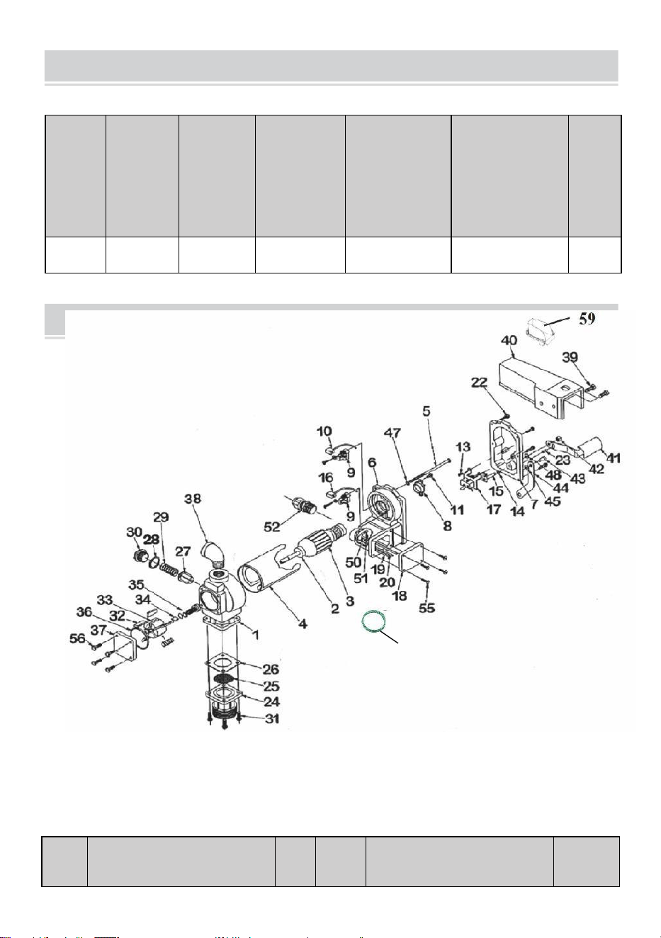
-
22
-
PARTS LIST
SECIFICATIONS
Modell
o
Voltagg
io
Ingresso
(W)
Portata
(gal/min
)
Tubo di
ingresso
specificazio
ne
( pollice )
Tubo di
scarico
specificazio
ne
( pollice )
GW
(kg)
Il KEX-
20
DC12V
400
20
1
1
11.28
RIF#
DESCRIZIONE
Fuori
Orari
o
RIF#
DESCRIZIONE
Fuori
Orario
60

-
23
-
1
POMPAGGIO
1
34
ROTORE CHIAVE
1
2
PALLA CUSCINETTO
2
35
ROTORE COPERTINA
1

-
24
-
3
ASSEMBLEA RMATURA
1
36
ROTORE COPERTINA
GUARNIZIONE
1
4
MOTORE
GRUPPO TELAIO/MAGNETE
1
37
MONTAGGIO DEL SIGILLO
1
5
BULLONE PASSANTE DA 1/4-
2×5
2
38
ACCIAIO GOMITO
1
6
MOTORE COLATA
ASSEMBLAGGIO
1
39
5/16-18×3/4HHCS
1
7
INTERRUTTORE PIATTO CON
AUTOBUS COSA
1
40
UGELLO COPERTINA
2
8
TERMICO PROTETTORE
1
41
INTERRUTTORE LEVA
1
9
SPAZZOLA TITOLARE
ASSEMBLAGGIO
2
42
5/15×18LOVK NOCE
1
10
NEGATIVO SPAZZOLA
ASSEMBLAGGIO
1
43
#14×S/8DRVE VITE
1
11
#8-32×1/2TORX
1
44
BLOCCAGGIO
COLLEGAMENTO
1
12
-
45
1/4 PRIMAVERA RONDELLA
1
13
#8-32×3/8 Torx-tipo
2
46
Elettroterapia SERRATURA
RONDELLA
1
14
5/16 PRIMAVERA RONDELLA
1
47
-
15
INTERRUTTORE
ASSEMBLAGGIO
DELL'ALBERO
1
48
5/16 CONSERVAZIONE
SQUILLO
2
16
POSITIVEBRUSHASSEMBLY
1
49
TERRA FILO
1
17
LINEA INTERRUTTORE
1
50
-
18
GIUNZIONE SCATOLA
COPERTINA
1
51
#832×3/8TERRENO VITE
1
19
NEGATIVO FILO GUIDA
1
52
CAVO CONNETTORE
1
20
POSITIVO FILO GUIDA
1
53
-
-
21
-
54
-
-
22
10-24×3/4 Torx-tipo
6
55
10-24×.50TORX
4
23
5/32×1/2PIN
1
56
1/4-20×.5HHCS
4
24
INGRESSO FLANGIA
1
57
-
-
25
SCHERMO
1
58
-
-
26
INGRESSO GUARNIZIONE
1
59
OLIO RICEVIMENTO
SCATOLA
1
27
BYPASS VALVOLA
1
60
Terra Filo
1
28
PERCHÉ VALVOLA
GUARNIZIONE
1
29
BYPASS PRIMAVERA
1

-
25
-
30
BYPASS CAP
1
31
Formato 1/4-20×3/4HHCS
1
32
PALETTA
4
33
ROTORE
5


-
27
-
Técnico Apoyo y Garantía electrónica Certificado www.vevor.com/support
COMBUSTIBLE TRANSFERIR BOMBA
( individual )
PROPIETARIOS INSTALACIÓN,
OPERACIÓN, Y SEGURIDAD MANUAL
MODELO: KEX-20
Nosotros continuar a ser comprometido a proporcionar tú herramientas con competitivo precio.
"Ahorra la mitad", "mitad de precio" o cualquier otra expresión similar utilizada por nosotros
solo representa una estimar de ahorros tú podría beneficio de comprar cierto herramientas
con a nosotros comparado a el importantelas mejores marcas y no necesariamente significa
cubrir todas las categorías de herramientas que ofrecemos.Se le recuerda que debe
verificar cuidadosamente cuando realice un pedido con nosotros si está de hecho ahorrando
la mitad En comparación con el arriba importante marcas.
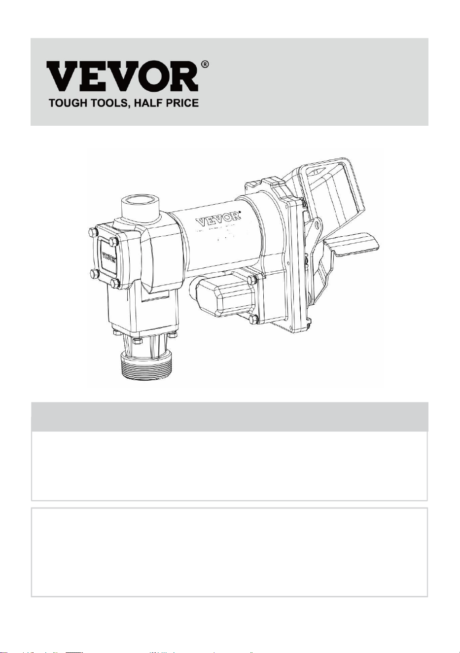
-
1
-
This is the original instruction, please read all manual instructions
carefully before operating. VEVOR reserves a clear interpretation of our
user manual. The appearance of the product shall be subject to the
product you received. Please forgive us that we won't inform you again if
there are any technology or software updates on our product.
FUEL TRANSFER PUMP
MODELO: KEX-20
Have product questions? Need technical support? Please feel free to
contact us:
Technical Support and E-Warranty Certificate
www.vevor.com/support
NEED HELP? CONTACT US!

-
2
-
SAFETY INFORMATION
WARNING! Electrical wiring should be performed ONLY by a
licensed electrician in compliance with local, state, and national
electrical code NEC/ANSI/ NFPA 70, NFPA 30, and NFPA 30A, as
appropriate to the intended use of the pump. Threaded rigid conduit,
sealed fittings, and conductor seal should be used where applicable.
The pump must be properly grounded. Improper installation or use of
this pump can result in serious bodily injury, or death!
¡ADVERTENCIA! A asegurar seguro y apropiado operación de su
equipo,Es fundamental leer y cumplir todas las siguientes advertencias
de seguridad y Precauciones. La instalación o el uso inadecuados de
este producto pueden causar grave corporal lesión o ¡muerte!
NUNCA fume cerca de la bomba ni utilice la bomba cerca de llamas
abiertas. cuando bombeo a ¡Líquido inflamable! Fuego poder
¡resultado!
Se debe utilizar un filtro en la salida de la bomba para garantizar
que no haya partículas extrañas. material es transferido a el
combustible tanque.
Con rosca tubo articulaciones y Conexiones debe ser sellado con el
sellador o cinta selladora adecuada para minimizar la posibilidad de
Fugas.
Los tanques de almacenamiento deben Estar anclado de forma
segura para evitar movedizo o propinas cuando completo o vacío.
A minimizar estático electricidad construir arriba, usar solo estático
cable conductivo Manguera al bombear líquidos inflamables y
mantenga la boquilla de llenado en contacto con el recipiente ser
completado durante el relleno proceso.
El motor de la bomba está equipado con protección contra
sobrecarga térmica; sisobrecalentado, el motor se apagará

-
3
-
para evitar daños al bobinados.

-
4
-
INSTALLATION
WARNING! This product shall not be used to transfer fluids into
any type of aircraft.
WARNING! This product is not suited for use with fluids intended
for human consumption or fluids containing water.
La bomba de transferencia de combustible 20GMP está diseñada para
montarse en un tanque deslizante utilizandoLa brida de entrada roscada
que se suministra con la bomba. Su bomba cuenta con una Válvula de
derivación integral para recircular el fluido cuando la bomba está en
funcionamiento. con el boquilla cerrado.
WARNING! This product is not suited for use with fluids intended
for human consumption or fluids containing water.
CAUTION! Do not use additional check valves or foot valves
unless they have a proper pressure relief valve built into them. Note that
additional check valves will reduce rate of flow.

-
5
-
CAUTION! A pressure retaining fill cap can be used to reduce fuel
loss through evaporation, but note that it will reduce the flow rate.
CAUTION! Threaded pipe joints and connections must be sealed
with the appropriate sealant or sealant tape to prevent the possibility of
leaks.
WARNING! 20GMP fuel transfer pumps are designed for use with
stationary and mobile tank applications. While DC powered units are
excellent choice for mobile applications, anchoring the tank to which the
pump is mounted is paramount to ensure no movement in transit.
Failure to secure the tank to the vehicle can cause uncontrolled
movement, resulting in damage, injury, and potential fire.

-
6
-
Típico Patinar Tanque Instalación
El bomba monturas a el bitoque de a patinar tanque por forma de el
entrada brida. ElEl tubo de succión se enrosca en la parte inferior de la
brida de entrada y debe extenderse hastauna longitud que lo ubique al
menos a 3” del fondo del tanque. El patín tanque debería estar equipado
con un respiradero tapa.
Materiales:
Tubo de succión telescópico de 1” extendido a una longitud que se
extenderá hasta A 3” del fondo del tanque cuando se atornilla al
adaptador del tanquecon el adaptador del tanque atornillado a la
brida del tanque (ver TANQUE DESLIZANTE) INSTALACIÓN
diagrama).
Con rosca tubo articulación sellador adecuado para solicitud.

-
7
-
Instalación Procedimiento:
13. Hilo el 1” tubo en el tanque adaptador. Sello trapos líquido ajustado
conadecuado sellador. (Cifra 1)
Típico Patinar Tanque Instalación (continúa)
14. Atornille la brida de entrada (con el tubo de succión) en el tapón
del tanque; séllelotrapos líquido ajustado con adecuado hilo
sellador (Cifra 2).

-
8
-
ELECTRICAL WIRING
15. Monte la bomba en el adaptador; asegurándose de que el sello y la
pantalla esténinstalado como mostrado. (Cifra 3).
CAUTION! DC powered pumps are designed to operate on either
12 or 24 VDC (depending on model). Where applicable, use the
supplied battery cable to supply power to the pump from a 12 or 24
VDC battery. A 40 amp fuse (20 amp fuse on 24 VDC motors) should be
installed on the battery cable to protect the wire in case of electrical
short.

-
9
-
CAUTION! Voltage drop in wiring varies depending on the
distance from the battery to the pump and the gauge of the wire used. If
the distance is greater than 20’, refer to national, international, or local
electrical codes to ensure the wire is of the correct size for this
application.
Instrucciones Antes Proceder Con Cableado de CC
La bomba debe estar conectada eléctricamente al tanque de suministro o
al bastidor del vehículo. Para unir eléctricamente la bomba, retire el
tornillo de unión verde ubicado al lado Tapa de la caja de conexiones.
Inserte este tornillo a través del ojal de la tapa verde provista. unión cable
asamblea y volver a sujetar él de forma segura a el bomba. El otro finde el
cable es a ser despojado de aislamiento y el desnudo cable de forma
segura garantizadoa el vehículo / tráiler marco o patinar tanque.
WARNING! Do not connect the positive or negative power to the
green screw or wire as this could cause a fire.
Alambrado Instrucciones
25. Eliminar zapatillas eléctrico unión caja cubrir y enderezar el 2
cables a Haga que los extremos pelados del cable sean
accesibles desde el exterior. unión caja.
26. Tornillo amueblado cable conector en TNP* conducto apertura en
bombaunión caja.
27. Banda 6 pulgadas de el exterior cubierta de uno fin de el

-
10
-
amueblado

-
11
-
eléctrico cable ser cuidadoso no a daño el negro y rojo cable
aislamiento.
28. Aflojar cable conector tuerca y aprobar el despojado fin de el
amueblado cable a través de el cable Conector. Apretar el cable
conector tuerca.
29. Banda 1
⁄
2 pulgada de el a i s i l a c i ó n de
el fin s de el rojo y negro Cables de conexión .
Con las tuercas para cables suministradas, conecte estos cables a la
bomba. cables pareo el bandera. Ser seguro No desnudo cable es
expuesto.
30. Doble los cables dentro de la caja de conexiones y vuelva a colocar
la tapa asegurándose de que la juntaestá en su lugar. Asegúrese de
que todos los tornillos estén colocados de manera que no haya
espacio entre el cubrir y el unión caja.
Alambrado A A Vehículo Eléctrico Sistema
17. Pase los cables eléctricos a la fuente del sistema de energía del
vehículo, sujetando los cables según sea necesario y protegiéndolos
de objetos afilados. bordes, calor, y cualquier cosa que podría daño el
cables.
18. Para determinar si el sistema eléctrico del vehículo es negativo (-) o
positivo (+) tierra, verifique la marca de la batería del terminal que
está cableado a El chasis del vehículo o el bloque motor. El cable rojo
de la bomba Conéctelo al borne positivo de la batería y el cable negro
de la bomba. conectar a batería negativa correo.
19. Conecte un extremo del portafusibles al extremo del cable sin
conexión a tierra. Hacer a sólido eléctrico conexión con el otro fin de
el fusible titularal lado sin conexión a tierra de la batería, lo más cerca
de la batería como sea posible posible. Hacer a sólido eléctrico
conexión a el conectado a tierra lado de el batería con el cable
restante. El terminal de la batería o el extremo de la batería cable es
recomendado.
20. Controlar todo Conexiones a hacer seguro ellos son conectado por
Instrucciones y todos los códigos eléctricos. Instale el fusible de 40
amperios (20 amperios) fusible en instalaciones de 24 VCC) en el

-
12
-
portafusibles. La instalación ahora estácompleto.
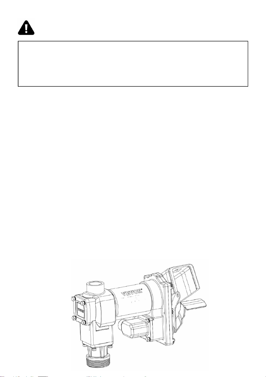
-
13
-
WARNING! Do not attempt to power the pump from vehicle wiring
smaller than 12 gage such as the cigarette lighter wire because these
thin wires could overheat and cause a fire.
corriente continua Alambrado (continúa)
Para Patinar Montado Tanques
13. Pase los cables eléctricos a la fuente de energía, sujetando los
cables comonecesarios y protegerlos de bordes afilados, calor y
cualquier cosa eso podría daño el cables.
14. Conecte un extremo del portafusibles al cable rojo de la bomba, lo
más cerca posible. la batería/fuente de alimentación lo más
cerca posible. Haga una conexión eléctrica sólida Conexión al
terminal positivo de la fuente de alimentación con el otroextremo del
portafusibles. Haga una conexión sólida con la bomba negra cable a
el negativo Terminal de el fuerza fuente.
15. Verifique todas las conexiones para asegurarse de que estén
conectadas correctamente. Instrucciones y todos los códigos
eléctricos. Instale el fusible de 40 amperios (20 amperios) fusible en
24 VCC instalaciones) en el fusible titular. El instalación es ahora
completo.
-
14
-
corriente continua Alambrado Diagrama

-
15
-
WARNING! Always keep the nozzle in contact with the container
being filled during the filling process to minimize the possibility of static
electricity build up.
OPERATING INSTRUCTIONS
13.
Si entonces equipado, reiniciar metro a “0” (hacer no reiniciar
mientras en usar como esto voluntadcausa daño a el metro).
14. Eliminar dispensando boquilla de boquilla bota.
15. Mueva la palanca del interruptor a la posición “ON” para encender
la bomba (figura 1).4.Insertar el dispensando boquilla en el recipiente a
ser completado.
17. Accione la boquilla para dispensar el líquido; suelte la boquilla
cuando alcance la cantidad deseada.cantidad de El líquido tiene
estado dispensado.
“ON”positiong
Figure 1

-
16
-

-
17
-
18. Mover cambiar palanca a el "APAGADO" posición (Cifra 2) a doblar
apagado el bomba.
19. Eliminar el dispensando boquilla de el recipiente ser completado y
almacenar élen el Boquilla de arranque.
Bloqueo con candado
Su bomba boquilla poder ser con candado a el bomba para agregado
seguridad. Con el bomba transformado apagado, y el boquilla en el
almacenado posición, a candado poder serinsertado A través de la cierre
enlace y el Mango de boquilla.
El enlace de bloqueo se encuentra en el lado de la boquilla de la
bomba y se puedepivotado en posición a trabajar con a variedad de
boquillas ( Figura 3 ).
“OFF”positiong
Figure 2
locking Link
Figure 3

-
18
-

-
19
-
WARNING! DO NOT open or attempt to repair the motor on your
pump. Return it to the place of purchase for service. Opening the motor
case can compromise the integrity of the Explosion Proof construction
and will void any existing warranty and certification.
WARNING! Be certain all power to the pump is disconnected prior
to performing any service or maintenance.
TROUBLESHOOTING
La siguiente guía de solución de problemas se proporciona para ofrecer
un diagnóstico básico. Asistencia en caso de que encuentre un servicio
anormal de su 20GMPcombustible transferir producto.

-
20
-
Síntoma
Causa
Cura
r
La bomba
no funciona
principal.
1. Línea de succión
problema.
Controlar para Fugas o obstrucciones en succión
línea.
2. Derivación válvula
abierto.
Eliminar y inspeccionar válvula; debe mover con
libertad & ser
gratis de escombros.
3. Paletas pega.
Controlar Paletas y ranuras para mellas, rebabas y
tener puesto.
4. Excesivo rotor o veleta
tener puesto.
Inspeccionar rotor & Paletas para excesivo tener
puesto o
daño; reemplazar si necesario.
5. Vapor Cerrar con llave.
Reducir la distancia vertical y horizontal
desdebomba a líquido; eliminar automático
boquilla.
Bajo capacidad.
1. Excesivo suciedad en
pantalla.
Eliminar y limpio pantalla.
2. Línea de succión
problema.
Verifique la línea de succión para detectar fugas
o restricciones; puedeser también pequeño,
también largo o no hermético.
3. Derivación válvula pega.
Eliminar y inspeccionar válvula; debe mover con
libertad & ser
gratis de escombros.
4. Salida obstruido.
Controlar bomba salida, manguera, boquilla y filtrar
para
bloqueo.
5. Paletas pega.
Controlar Paletas y ranuras para tener puesto.
6. Excesivo rotor o veleta
tener puesto.
Inspeccionar rotor & Paletas para excesivo
tener puesto odaño; reemplazar si
necesario.
7. Manguera o boquilla
daño.
Reemplazar manguera o boquilla.
8. Atascado filtrar.
Reemplazar filtrar.
9. Bajo nivel de líquido
nivel.
Llenar tanque.
La bomba
1. Incorrecto Voltaje.
Controlar entrante voltaje de línea mientras La
bomba es
correr.
2. Paletas pega.
Inspeccionar Paletas y ranuras para mellas,
rebabas y tener puesto.

-
21
-
funciona
despacio.
3. Alambrado problema.
Controlar para perder Conexiones.
4. Motor problema.
Devolver a lugar de compra.

-
22
-
TROUBLESHOOTING (CONT’D)
El motor se para /
se fundegolpes o
termales viajes
de protección
repetidamente.
1. Derivación válvula pega.
Eliminar y inspeccionar válvula; debe mover
con libertad
& ser libre de escombros.
2. Bajo Voltaje.
Controlar entrante voltaje de línea mientras
bombea es
correr.
3. Excesivo rotor o Desgaste de
paletas.
Controlar rotor & Paletas para excesivo tener
puesto o
daño.
4. Escombros en bomba cavidad.
Limpio escombros de bomba cavidad.
Motor se
sobrecalie
nta.
1. Bombeo alto viscosidad fluidos.
Estos fluidos poder solo ser emocionado por
corto
períodos de tiempo (menos de 30
minutos de servicio)ciclo).
2. Obstruido pantalla.
Eliminar y limpio pantalla.
3. Restringido succión tubo.
Eliminar y limpio tubo.
4. Motor falla.
Devolver a lugar de compra.
5. Bomba bloqueo del rotor.
Limpio y controlar bomba Rotor y Paletas.
Motor
Inoperante.
1. No fuerza.
Controlar entrante fuerza.
2. Cambiar falla.
Reemplazar cambiar .
3. Motor falla.
Devolver a lugar de compra.
4. Térmico protector falla.
Devolver a lugar de compra.
5. Incorrecto/suelto alambrado.
Controlar alambrado.
Líquido fuga.
1. Junta tórica defectuosa
empaquetadora.
Controlar todo junta tórica Juntas.
2. Sucio eje sello.
Limpio sello & sello cavidad.
3. Eje defectuoso sello.
Reemplazar sello.
4. Incompatible líquido.
Referirse mojado regiones lista a líquido
fabricante.
5. Perder sujetadores.
Apretar sujetadores.
Bomba tararea
pero
voluntad no
funcionar.
1. Motor falla.
Devolver a lugar de compra.
2. Roto rotor llave.
Eliminar todo escombros & reemplazar llave.
-
23
-
PARTS LIST
SECIFICATIONS
Model
o
Voltaje
Entrada
(W)
Caudal
(GPM)
Tubo de
entrada
especificaci
ón
( pulgada )
Tubo de
salida
especificaci
ón
( pulgada )
GW
(kilog
ramo)
KEX-20
12 V CC
400
20
1
1
11.28
ÁRBI
TRO#
DESCRIPCIÓN
OTY
ÁRBIT
RO#
DESCRIPCIÓN
OTY
1
CARCASA DE BOMBA
1
34
ROTOR LLAVE
1
60

-
24
-
2
PELOTA COJINETE
2
35
ROTOR CUBRIR
1

-
25
-
3
ENSAMBLAJE DE
ARMADURA
1
36
ROTOR CUBRIR
EMPAQUETADORA
1
4
MOTOR
CONJUNTO MARCO/IMANES
1
37
ENSAMBLAJE DE SELLOS
1
5
PERNO PASANTE DE 1/4-2×5
2
38
ACERO CODO
1
6
MOTOR FUNDICIÓN
ASAMBLEA
1
39
5/16-18×3/4 pulgadas de alto x
1/2 pulgada de ancho
1
7
CAMBIAR LÁMINA CON
AUTOBÚS BISAGRA
1
40
BOQUILLA CUBRIR
2
8
TÉRMICO PROTECTOR
1
41
CAMBIAR PALANCA
1
9
CEPILLAR TITULAR
ASAMBLEA
2
42
5/15×18LOVK TUERCA
1
10
NEGATIVO CEPILLAR
ASAMBLEA
1
43
#14×S/8CONDUCCIÓN
TORNILLO
1
11
#8-32×1/2TORX
1
44
CIERRE ENLACE
1
12
-
45
1/4 PRIMAVERA ARANDELA
1
13
#8-32×3/8 Torx
2
46
ECT CERRAR ARANDELA
1
14
5/16 PRIMAVERA ARANDELA
1
47
-
15
CAMBIAR CONJUNTO DEL
EJE
1
48
5/16 RETENCIÓN ANILLO
2
16
CONJUNTO DE ESCOBILLAS
POSITIVAS
1
49
SUELO CABLE
1
17
LÍNEA CAMBIAR
1
50
-
18
UNIÓN CAJA CUBRIR
1
51
#832×3/8TIERRA TORNILLO
1
19
NEGATIVO CABLE DIRIGIR
1
52
CABLE CONECTOR
1
20
POSITIVO CABLE DIRIGIR
1
53
-
-
21
-
54
-
-
22
10-24×3/4 Torx
6
55
10-24 x 0,50 TORX
4
23
5/32 × 1/2 PIN
1
56
1/4-20×0,5 HHCS
4
24
ENTRADA BRIDA
1
57
-
-
25
PANTALLA
1
58
-
-
26
ENTRADA
EMPAQUETADORA
1
59
ACEITE RECEPCIÓN CAJA
1
27
DERIVACIÓN VÁLVULA
1
60
Suelo Cable
1
28
DESVENTAJA VÁLVULA
EMPAQUETADORA
1
29
DERIVACIÓN PRIMAVERA
1
30
DERIVACIÓN TAPA
1
31
1/4-20×3/4 pulgadas de alto x
1/4 pulgadas de ancho x 1/4
1

-
26
-
pulgadas de profundidad
32
VELETA
4
33
ROTOR
5


-
28
-
Techniczny Wsparcie I E-gwarancja Certyfikat www.vevor.com/support
PALIWO PRZENOSIĆ POMPA ( pojedyncza )
WŁAŚCICIELE INSTALACJA,
DZIAŁANIE, I BEZPIECZEŃSTWO PODRĘCZNIK
MODEL: KEX-20
My Kontynuować Do Być zaangażowany Do dostarczać Ty narzędzia z konkurencyjny cena.
„Oszczędź połowę”, „Połowa ceny” lub jakiekolwiek inne podobne wyrażenia używane
przez nas oznaczają wyłącznie oszacować z oszczędności Ty móc korzyść z kupowanie
niektórzy narzędzia z nas porównano Do ten głównynajlepszych marek i niekoniecznie
oznacza to, że obejmuje wszystkie kategorie narzędzi oferowanych przez nas.uprzejmie
przypominamy o konieczności dokładnego sprawdzenia, czy składając u nas zamówienie,
Właściwie oszczędzanie połowy wobec z szczyt główny marki.

-
1
-
This is the original instruction, please read all manual instructions
carefully before operating. VEVOR reserves a clear interpretation of our
user manual. The appearance of the product shall be subject to the
product you received. Please forgive us that we won't inform you again if
there are any technology or software updates on our product.
FUEL TRANSFER PUMP
MODEL: KEX-20
Have product questions? Need technical support? Please feel free to
contact us:
Technical Support and E-Warranty Certificate
www.vevor.com/support
NEED HELP? CONTACT US!

-
2
-
SAFETY INFORMATION
WARNING! Electrical wiring should be performed ONLY by a
licensed electrician in compliance with local, state, and national
electrical code NEC/ANSI/ NFPA 70, NFPA 30, and NFPA 30A, as
appropriate to the intended use of the pump. Threaded rigid conduit,
sealed fittings, and conductor seal should be used where applicable.
The pump must be properly grounded. Improper installation or use of
this pump can result in serious bodily injury, or death!
OSTRZEŻENIE! Do zapewnić bezpieczna i właściwe działanie z
twój sprzęt,przeczytanie i przestrzeganie wszystkich poniższych
ostrzeżeń dotyczących bezpieczeństwa jest niezwykle ważne środki
ostrożności. Nieprawidłowa instalacja lub użytkowanie tego produktu
może spowodować poważny cieleśnie obrażenia Lub śmierć!
NIGDY nie pal w pobliżu pompy ani nie używaj pompy w pobliżu
otwartego ognia. Kiedy pompowanie A łatwopalna ciecz! Ogień Móc
wynik!
Na wylocie pompy należy zastosować filtr, aby mieć pewność, że
nie przedostaną się do niej żadne ciała obce. tworzywo Jest
przeniesiony Do ten paliwo zbiornik.
Gwintowany rura stawy I znajomości musieć Być zapieczętowany z
ten odpowiedniego uszczelniacza lub taśmy uszczelniającej, aby
zminimalizować możliwość przecieki.
Zbiorniki magazynowe muszą być bezpiecznie zakotwiczone, aby
zapobiec przesuwalny Lub napiwki Kiedy pełny lub pusty.
Do zminimalizować statyczny elektryczność zbudować w górę,
używać tylko statyczny drut przewodzącywąż podczas pompowania
łatwopalnych płynów i trzymaj dyszę napełniającą w kontakt z ten
pojemnik istnienie wypełniony podczas ten pożywny proces.
Silnik pompy wyposażony jest w zabezpieczenie przed

-
3
-
przeciążeniem termicznym; jeżeliprzegrzany, silnik wyłączy się,
aby zapobiec uszkodzeniu uzwojenia.

-
4
-
INSTALLATION
WARNING! This product shall not be used to transfer fluids into
any type of aircraft.
WARNING! This product is not suited for use with fluids intended
for human consumption or fluids containing water.
Pompa do transferu paliwa 20GMP jest przeznaczona do montażu na
zbiorniku paletowym za pomocągwintowany kołnierz wlotowy dostarczany
z pompą. Twoja pompa ma zintegrowany zawór obejściowy umożliwiający
recyrkulację płynu podczas pracy pompy z ten dysza Zamknięte.
WARNING! This product is not suited for use with fluids intended
for human consumption or fluids containing water.
CAUTION! Do not use additional check valves or foot valves
unless they have a proper pressure relief valve built into them. Note that
additional check valves will reduce rate of flow.

-
5
-
CAUTION! A pressure retaining fill cap can be used to reduce fuel
loss through evaporation, but note that it will reduce the flow rate.
CAUTION! Threaded pipe joints and connections must be sealed
with the appropriate sealant or sealant tape to prevent the possibility of
leaks.
WARNING! 20GMP fuel transfer pumps are designed for use with
stationary and mobile tank applications. While DC powered units are
excellent choice for mobile applications, anchoring the tank to which the
pump is mounted is paramount to ensure no movement in transit.
Failure to secure the tank to the vehicle can cause uncontrolled
movement, resulting in damage, injury, and potential fire.

-
6
-
Typowy Poślizg Zbiornik Instalacja
Ten pompa mocowania Do ten korek z A poślizg zbiornik przez sposób z
ten wlot kołnierz. Tenrura ssąca jest wkręcana w dolną część kołnierza
wlotowego i musi sięgać dodługość, która umieszcza go co najmniej 3” od
dna zbiornika. Płoza zbiornik powinien być wyposażonym z odpowietrznik
czapka.
Przybory:
1” teleskopowa rura ssąca rozciągnięta na długość, która pozwoli na
w odległości 3” od dna zbiornika po wkręceniu w adapter zbiornikaz
adapterem zbiornika wkręconym w kołnierz zbiornika (patrz
ZBIORNIK SKID INSTALACJA diagram).
Gwintowany rura wspólny uszczelniacz odpowiedni Do aplikacja.
-
7
-
Instalacja Procedura:
16. Nitka ten 1” rura do ten zbiornik adapter. Foka wątki płyn obcisły z
odpowiedni uszczelniacz. (Postać 1)
Typowy Poślizg Zbiornik Instalacja (cd.)
17. Wkręcić kołnierz wlotowy (z rurą ssącą) do korka zbiornika;
uszczelnićwątki płyn obcisły z odpowiedni nitka uszczelniacz
(Postać 2).
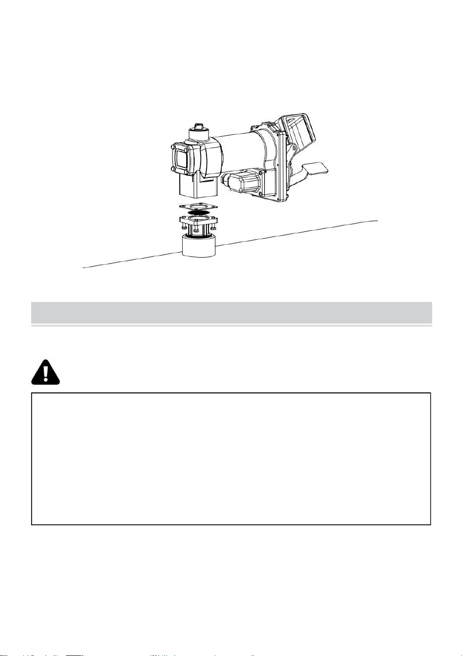
-
8
-
ELECTRICAL WIRING
18. Zamontuj pompę na adapterze, upewniając się, że uszczelka i sitko
sązainstalowany Jak pokazano. (Postać 3).
CAUTION! DC powered pumps are designed to operate on either
12 or 24 VDC (depending on model). Where applicable, use the
supplied battery cable to supply power to the pump from a 12 or 24
VDC battery. A 40 amp fuse (20 amp fuse on 24 VDC motors) should be
installed on the battery cable to protect the wire in case of electrical
short.

-
9
-
CAUTION! Voltage drop in wiring varies depending on the
distance from the battery to the pump and the gauge of the wire used. If
the distance is greater than 20’, refer to national, international, or local
electrical codes to ensure the wire is of the correct size for this
application.
Instrukcje Zanim Postępowanie Z Okablowanie DC
Pompa musi być podłączona elektrycznie do zbiornika lub ramy pojazdu.
Aby połączyć pompę elektrycznie, należy usunąć zieloną śrubę łączącą
znajdującą się obok pokrywa skrzynki przyłączeniowej. Włóż tę śrubę
przez oczko w dostarczonym zielonym wiązanie drut montaż I zapiąć
ponownie To bezpiecznie Do ten pompa. Ten Inny koniecz ten drut Jest Do
Być rozebrany z izolacja I ten goły drut bezpiecznie wolnocłowyDo ten
pojazd / przyczepa rama Lub poślizg zbiornik.
WARNING! Do not connect the positive or negative power to the
green screw or wire as this could cause a fire.
Okablowanie Instrukcje
31. Usunąć lakierki elektryczny węzeł skrzynka okładka I
wyprostować ten 2przewody Do umożliwić dostęp do
odsłoniętych końcówek przewodów poza węzeł skrzynka.
32. Śruba umeblowany kabel złącze do NPT* przewód otwór W pompa
węzeł skrzynka.
33. Pas 6 cale z ten zewnętrzny pokrycie z jeden koniec z ten

-
10
-
umeblowany

-
11
-
elektryczny kabel istnienie ostrożny nie Do szkoda ten czarny I
czerwony drutizolacja.
34. Poluzować kabel złącze nakrętka I przechodzić ten rozebrany koniec z
ten umeblowanykabel Poprzez ten kabel złącze. Dokręcać ten kabel
złącze nakrętka.
35. Pasek 1
⁄
2 ja nie z on i z o l i z a c j a z on
koniec s z on czerwony I czarny kable kablowe .
Za pomocą dostarczonych nakrętek kablowych podłącz te kable do
pompy przewody dopasowanie ten zabarwienie. Być Jasne NIE goły
drut Jest narażony.
36. Złóż przewody do puszki przyłączeniowej i załóż pokrywę, upewniając
się, że uszczelka jest szczelna. jest na miejscu. Upewnij się, że
wszystkie śruby są osadzone, tak aby nie było wolnej przestrzeni
między ten okładka i węzeł skrzynka.
Okablowanie Do A Pojazd Elektryczny System
21. Przeprowadź przewody elektryczne do źródła zasilania pojazdu,
podtrzymywanie przewodów w razie potrzeby i ochrona ich przed
ostrymi przedmiotami krawędzie, ciepło, I cokolwiek co mógł szkoda
ten przewody.
22. Aby określić, czy układ elektryczny pojazdu jest ujemny (-) czy
dodatni (+) uziemienie, sprawdź oznaczenie akumulatora na zacisku,
do którego jest podłączony rama pojazdu lub blok silnika. Czerwony
przewód z pompy będzie podłącz do dodatniego bieguna akumulatora,
a czarny przewód z pompy będzie łączyć Do ujemna bateria post.
23. Podłącz jeden koniec uchwytu bezpiecznika do końca
nieuziemionego przewodu. Robić A solidny elektryczny połączenie z
ten Inny koniec z ten bezpiecznik uchwyt do nieuziemionej strony
akumulatora, tak blisko akumulatora, jak to możliwe możliwy. Robić A
solidny elektryczny połączenie Do ten uziemiony strona z ten
akumulator z pozostałym przewodem. Zacisk akumulatora lub koniec
bateria kabel Jest zalecony.
24. Sprawdzać Wszystko znajomości Do robić Jasne Oni Czy połączony
za instrukcje i wszystkie kody elektryczne. Zainstaluj bezpiecznik 4 0
amperów (20 amperów) bezpiecznik w instalacjach 24 VDC) w

-
12
-
uchwycie bezpiecznika. Instalacja jest terazkompletny.

-
13
-
WARNING! Do not attempt to power the pump from vehicle wiring
smaller than 12 gage such as the cigarette lighter wire because these
thin wires could overheat and cause a fire.
Prąd stały Okablowanie (cd.)
Dla Poślizg Zmontowany Czołgi
16. Przeprowadź przewody elektryczne do źródła zasilania,
podtrzymując przewody w sposóbkonieczne i chroniące je przed
ostrymi krawędziami, ciepłem i wszelkimi innymi To mógł szkoda ten
przewody.
17. Podłącz jeden koniec uchwytu bezpiecznika do czerwonego
przewodu pompy, jak najbliżej akumulator/źródło zasilania jak
najbardziej. Zrób solidne elektryczne połączenie z dodatnim
zaciskiem źródła zasilania z drugimkoniec uchwytu bezpiecznika.
Wykonaj solidne połączenie z czarną pompą drut Do ten negatywny
terminal z ten moc źródło.
18. Sprawdź wszystkie połączenia, aby upewnić się, że są prawidłowo
podłączone. instrukcje i wszystkie kody elektryczne. Zainstaluj
bezpiecznik 4 0 amperów (20 amperów) bezpiecznik W 24 VDC
instalacje) W ten bezpiecznik uchwyt. Ten instalacja Jest Teraz
kompletny.

-
14
-

-
15
-
Prąd stały Okablowanie Diagram

-
16
-
WARNING! Always keep the nozzle in contact with the container
being filled during the filling process to minimize the possibility of static
electricity build up.
OPERATING INSTRUCTIONS
16.
Jeśli Więc wyposażony, nastawić metr Do „0” (Do nie nastawić
chwila W używać jak to będzieprzyczyna szkoda Do ten metr).
17. Usunąć wydawanie dysza z dysza uruchomić.
18. Aby włączyć pompę, należy przesunąć dźwignię przełącznika do
pozycji „ON” (rysunek 1).4. Wstaw ten wydawanie dysza do ten pojemnik
Do Być wypełniony.
20. Użyj dyszy, aby dozować płyn; zwolnij dyszę, gdy uzyskasz
pożądaną ilość płynu.kwota z płyn ma został wydano.
“ON”positiong
Figure 1

-
17
-
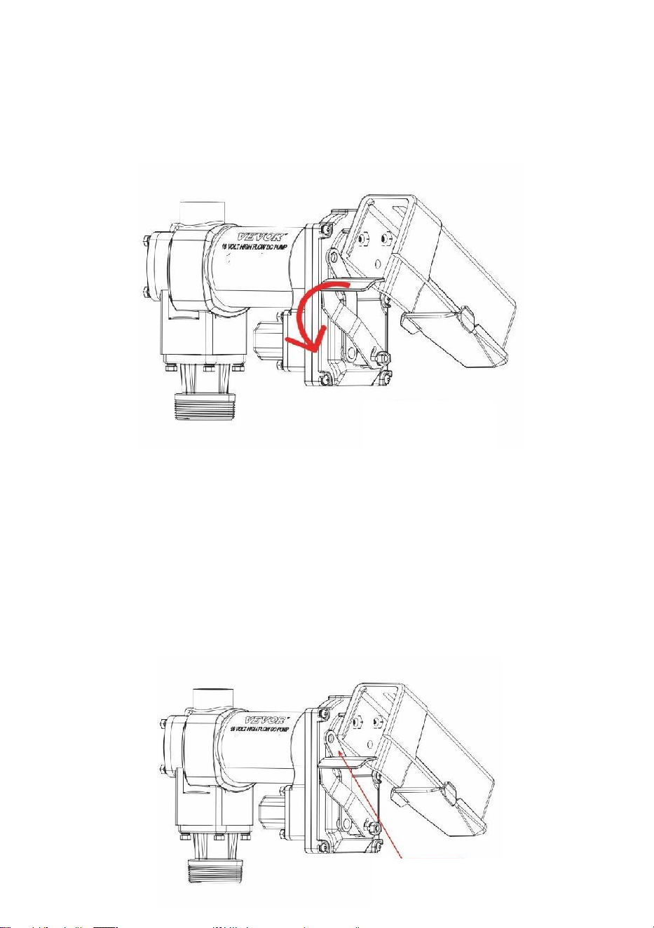
-
18
-
21. Przenosić przełącznik dźwignia Do ten "WYŁĄCZONY" pozycja (Postać
2) Do zakręt wyłączony ten pompa.
22. Usunąć ten wydawanie dysza z ten pojemnik istnienie wypełniony I
sklep ToW ten osłona dyszy.
Blokowanie
Twój pompa dysza Móc Być zamknięty na kłódkę Do ten pompa Do w
dodatku bezpieczeństwo. Zten pompa obrócony wyłączony, I ten dysza W
ten przechowywany pozycja, A kłódka Móc Byćwłożono przez zamykający
połączyć I ten uchwyt dyszy.
Łącznik blokujący znajduje się po stronie dyszy pompy i można go
obrócony do pozycja Do praca z A różnorodność dysze ( Rysunek 3 ).
“OFF”positiong
Figure 2
locking Link
Figure 3

-
19
-

-
20
-
WARNING! DO NOT open or attempt to repair the motor on your
pump. Return it to the place of purchase for service. Opening the motor
case can compromise the integrity of the Explosion Proof construction
and will void any existing warranty and certification.
WARNING! Be certain all power to the pump is disconnected prior
to performing any service or maintenance.
TROUBLESHOOTING
Poniższy przewodnik rozwiązywania problemów ma na celu zapewnienie
podstawowych informacji diagnostycznych pomoc w przypadku
wystąpienia nieprawidłowej obsługi przez 20GMPpaliwo przenosić
produkt.

-
21
-
Objaw
Przycz
yna
Wyle
czyć
Pompa nie
będzie
główny.
1. Przewód ssący problem.
Sprawdzać Do przecieki Lub przeszkody W ssanie
linia.
2. Objazd zawór Otwarte.
Usunąć I sprawdzać zawór; musieć przenosić
swobodnie & Być
bezpłatny z gruz.
3. Łopatki klejący.
Sprawdzać łopatki I sloty Do nacięcia, zadziory I
nosić.
4. Nadmierny wirnik Lub
wiatrowskaz
nosić.
Sprawdzać wirnik & łopatki Do nadmierny nosić
Lub
szkoda; zastępować Jeśli niezbędny.
5. Para Zamek.
Zmniejsz odległość pionową i poziomą od
pompa Do płyn; usunąć automatyczny
dysza.
Niski
pojemność.
1. Nadmierny brud W ekran.
Usunąć I czysty ekran.
2. Przewód ssący problem.
Sprawdź przewód ssący pod kątem
nieszczelności lub ograniczeń; może toByć zbyt
mały, zbyt długo czy nie hermetyczny.
3. Objazd zawór klejący.
Usunąć I sprawdzać zawór; musieć przenosić
swobodnie & Być
bezpłatny z gruz.
4. Wylot zablokowany.
Sprawdzać pompa wylot, wąż gumowy, dysza i filtr
dla
zablokowanie.
5. Łopatki klejący.
Sprawdzać łopatki I sloty Do nosić.
6. Nadmierny wirnik Lub
wiatrowskaznosić.
Sprawdzać wirnik & łopatki Do nadmierny
nosić Lubszkoda; zastępować Jeśli
niezbędny.
7. Wąż gumowy Lub dysza
szkoda.
Zastępować wąż gumowy Lub dysza.
8. Zatkany filtr.
Zastępować filtr.
9. Niski poziom płynu
poziom.
Wypełnić zbiornik.
Pompa
1. Błędny woltaż.
Sprawdzać przybywający napięcie sieciowe chwila
pompa jest
działanie.
2. Łopatki klejący.
Sprawdzać łopatki I sloty Do nacięcia, zadziory I
nosić.

-
22
-
pracuje
powoli.
3. Okablowanie problem.
Sprawdzać Do luźny znajomości.
4. Silnik problem.
Powrót Do miejsce z zakup.

-
23
-
TROUBLESHOOTING (CONT’D)
Silnik gaśnie /
bezpiecznikciosy
lub termiczne
wycieczki
ochronne
wielokrotnie.
1. Objazd zawór klejący.
Usunąć I sprawdzać zawór; musieć przenosić
swobodnie
& Być wolny od gruz.
2. Niski woltaż.
Sprawdzać przybywający napięcie sieciowe
podczas pompowania Jest
działanie.
3. Nadmierny wirnik Lub zużycie
łopatki.
Sprawdzać wirnik & łopatki Do nadmierny
nosić Lub
szkoda.
4. Gruz W pompa wgłębienie.
Czysty gruz z pompa wgłębienie.
Silnik
przegrzew
a się.
1. Pompowanie wysoki lepkość
płyny.
Te płyny Móc tylko Być pompowany dla krótki
okresy czasu (dyżur krótszy niż 30 minut)
cykl).
2. Zatkany ekran.
Usunąć I czysty ekran.
3. Ograniczony ssanie rura.
Usunąć I czysty rura.
4. Silnik awaria.
Powrót Do miejsce z zakup.
5. Pompa zablokowanie wirnika.
Czysty I sprawdzać pompa wirnik i łopatki.
Silnik
Nieczynny.
1. NIE moc.
Sprawdzać przybywający moc.
2. Przełącznik awaria.
Zastępować przełącznik .
3. Silnik awaria.
Powrót Do miejsce z zakup.
4. Termiczny ochraniacz awaria.
Powrót Do miejsce z zakup.
5. Niepoprawne/luźne
okablowanie.
Sprawdzać okablowanie.
Płyn przeciek.
1. Zły pierścień uszczelniający
uszczelka.
Sprawdzać Wszystko pierścień uszczelniający
uszczelki.
2. Brudny wał foka.
Czysty foka & foka wgłębienie.
3. Zły wał foka.
Zastępować foka.
4. Niezgodny płyn.
Wspominać zwilżony strony lista Do płyn
producent.
5. Luźny elementy złączne.
Dokręcać elementy złączne.
Pompa brzęczy
Ale
będzie nie działać.
1. Silnik awaria.
Powrót Do miejsce z zakup.
2. Złamany wirnik klawisz.
Usunąć Wszystko gruz & zastępować klawisz.
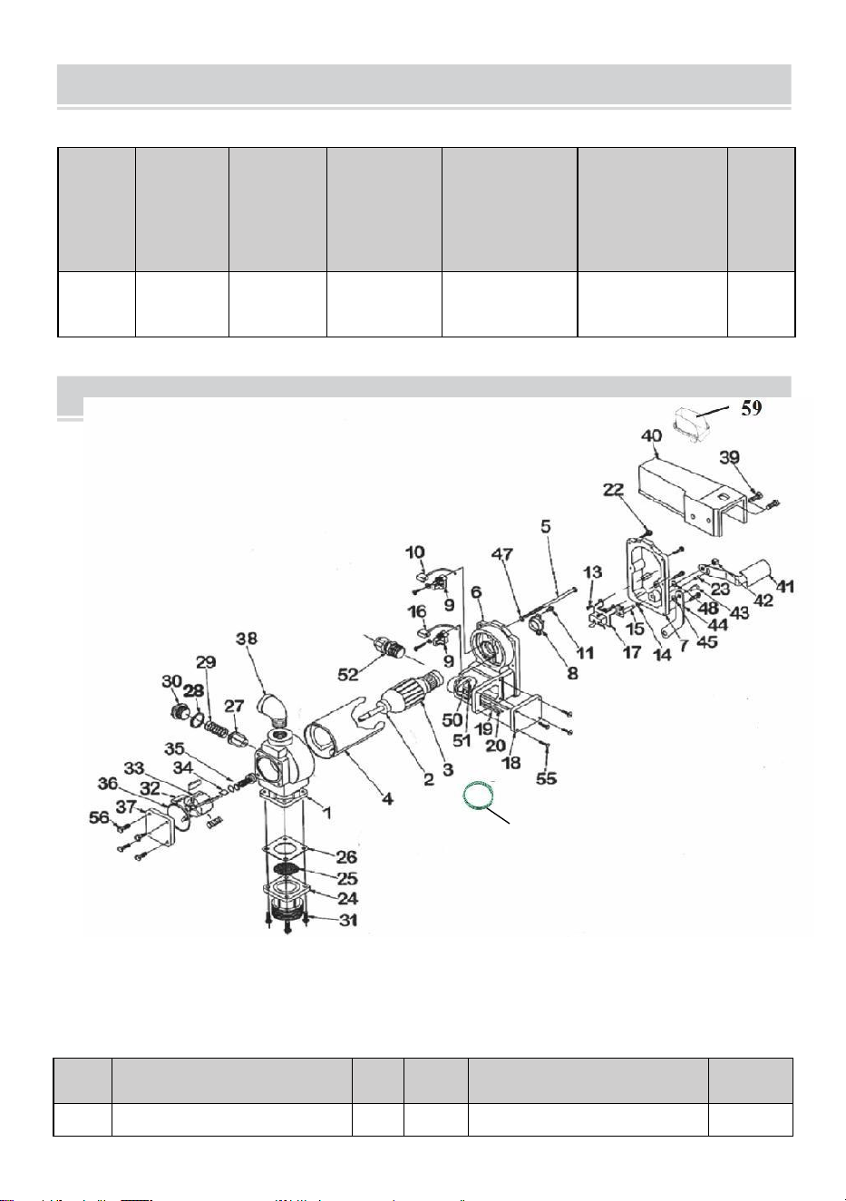
-
24
-
PARTS LIST
SECIFICATIONS
Model
Woltaż
Wejście
(W)
Przepływ
(GPM)
Rura
wlotowa
specyfikacja
( cal )
Rura
wylotowa
specyfikacja
( cal )
GW
(kg)
KEX-20
Prąd
stały 12
V
400
20
1
1
11.28
Nr
ref.
OPIS
OTY
Nr ref.
OPIS
OTY
1
POMPOWNIA
1
34
WIRNIK KLAWISZ
1
60

-
25
-
2
PIŁKA ŁOŻYSKO
2
35
WIRNIK OKŁADKA
1

-
26
-
3
MONTAŻ DOJRZAŁOŚCI
1
36
WIRNIK OKŁADKA
USZCZELKA
1
4
SILNIK
RAMA/ZESPÓŁ
MAGNETYCZNY
1
37
USZCZELNIENIE
MONTAŻOWE
1
5
ŚRUBA PRZELOTOWA 1/4-
2×5
2
38
STAL ŁOKIEĆ
1
6
SILNIK ODLEW MONTAŻ
1
39
5/16-18×3/4HHCS
1
7
PRZEŁĄCZNIK PŁYTA Z
AUTOBUS HING
1
40
DYSZA OKŁADKA
2
8
TERMICZNY OCHRANIACZ
1
41
PRZEŁĄCZNIK DŹWIGNIA
1
9
SZCZOTKA UCHWYT MONTAŻ
2
42
5/15×18LOVK NAKRĘTKA
1
10
NEGATYWNY SZCZOTKA
MONTAŻ
1
43
#14×S/8DRVE ŚRUBA
1
11
#8-32×1/2TORX
1
44
ZAMYKAJĄCY POŁĄCZYĆ
1
12
-
45
1/4 WIOSNA PRALKA
1
13
#8-32×3/8 TORX
2
46
ECT ZAMEK PRALKA
1
14
5/16 WIOSNA PRALKA
1
47
-
15
PRZEŁĄCZNIK ZESTAW
WAŁU
1
48
5/16 WSPORNIKOWY
PIERŚCIEŃ
2
16
POZYTYWNY MONTAŻ
SZCZOTKI
1
49
GRUNT DRUT
1
17
LINIA PRZEŁĄCZNIK
1
50
-
18
WĘZEŁ SKRZYNKA OKŁADKA
1
51
#832×3/8ZIEMIA ŚRUBA
1
19
NEGATYWNY DRUT OŁÓW
1
52
KABEL ZŁĄCZE
1
20
POZYTYWNY DRUT OŁÓW
1
53
-
-
21
-
54
-
-
22
10-24×3/4 TORX
6
55
10-24×.50TORX
4
23
5/32×1/2PIN
1
56
1/4-20×.5HHCS
4
24
WLOT KOŁNIERZ
1
57
-
-
25
EKRAN
1
58
-
-
26
WLOT USZCZELKA
1
59
OLEJ OTRZYMUJĄCY
SKRZYNKA
1
27
OBJAZD ZAWÓR
1
60
Grunt Drut
1
28
BYASS ZAWÓR USZCZELKA
1
29
OBJAZD WIOSNA
1
30
OBJAZD CZAPKA
1
31
1/4-20×3/4HHCS
1

-
27
-
32
WIATROWSKAZ
4
33
WIRNIK
5


-
29
-
Technisch Steun En E-Garantie Certificaat www.vevor.com/support
BRANDSTOF OVERDRACHT POMP ( enkel )
EIGENAARS INSTALLATIE,
WERKING, EN VEILIGHEID HANDMATIG
MODEL: KEX-20
Wij doorgaan naar zijn betrokken naar voorzien Jij hulpmiddelen met competitief prijs.
"Bespaar de helft", "halve prijs" of andere soortgelijke uitdrukkingen die wij gebruiken,
vertegenwoordigen slechts een schatting van besparingen Jij macht voordeel van kopen
zeker hulpmiddelen met ons vergeleken naar de belangrijktopmerken en betekent niet
noodzakelijkerwijs dat alle categorieën gereedschappen die wij aanbieden, worden gedekt.
UWij herinneren u eraan om bij het plaatsen van een bestelling bij ons zorgvuldig te
controleren of u: Eigenlijk de helft besparen in vergelijking met de bovenkant belangrijk
merken.

-
1
-
This is the original instruction, please read all manual instructions
carefully before operating. VEVOR reserves a clear interpretation of our
user manual. The appearance of the product shall be subject to the
product you received. Please forgive us that we won't inform you again if
there are any technology or software updates on our product.
FUEL TRANSFER PUMP
MODEL: KEX-20
Have product questions? Need technical support? Please feel free to
contact us:
Technical Support and E-Warranty Certificate
www.vevor.com/support
NEED HELP? CONTACT US!

-
2
-
SAFETY INFORMATION
WARNING! Electrical wiring should be performed ONLY by a
licensed electrician in compliance with local, state, and national
electrical code NEC/ANSI/ NFPA 70, NFPA 30, and NFPA 30A, as
appropriate to the intended use of the pump. Threaded rigid conduit,
sealed fittings, and conductor seal should be used where applicable.
The pump must be properly grounded. Improper installation or use of
this pump can result in serious bodily injury, or death!
WAARSCHUWING! Naar ervoor zorgen veilig en goed operatie
van jouw apparatuur,Het is van cruciaal belang om alle volgende
veiligheidswaarschuwingen te lezen en na te leven en
voorzorgsmaatregelen. Onjuiste installatie of gebruik van dit product kan
leiden tot serieus lichamelijk blessure of dood!
Rook NOOIT in de buurt van de pomp en gebruik de pomp niet in
de buurt van open vuur. wanneer pompen A brandbare vloeistof!
Vuur kan resultaat!
Er moet een filter op de uitlaat van de pomp worden gebruikt om
ervoor te zorgen dat er geen vreemde stoffen in het water
terechtkomen. materiaal is overgedragen naar de brandstof tank.
Met schroefdraad pijp gewrichten En verbindingen moeten zijn
verzegeld met de geschikte kit of kittape om de kans op lekken.
Opslagtanks moeten stevig verankerd zijn om te voorkomen
verschuiven of fooi geven wanneer vol of leeg.
Naar minimaliseren statisch elektriciteit bouwen omhoog, gebruik
alleen statisch draad geleidendslang bij het pompen van brandbare
vloeistoffen en houd het vulmondstuk in de buurt contact met de
houder wezen gevuld tijdens de vulling proces.
De pompmotor is voorzien van een thermische
overbelastingsbeveiliging; indienoververhit, zal de motor

-
3
-
uitschakelen om schade aan de wikkelingen.

-
4
-
INSTALLATION
WARNING! This product shall not be used to transfer fluids into
any type of aircraft.
WARNING! This product is not suited for use with fluids intended
for human consumption or fluids containing water.
De 20GMP brandstoftransportpomp is ontworpen om op een skidtank te
worden gemonteerd met behulp vande schroefdraadinlaatflens die bij de
pomp wordt geleverd. Uw pomp is voorzien van een geïntegreerde
bypassklep om de vloeistof te recirculeren wanneer de pomp in werking is
met de mondstuk gesloten.
WARNING! This product is not suited for use with fluids intended
for human consumption or fluids containing water.
CAUTION! Do not use additional check valves or foot valves
unless they have a proper pressure relief valve built into them. Note that
additional check valves will reduce rate of flow.

-
5
-
CAUTION! A pressure retaining fill cap can be used to reduce fuel
loss through evaporation, but note that it will reduce the flow rate.
CAUTION! Threaded pipe joints and connections must be sealed
with the appropriate sealant or sealant tape to prevent the possibility of
leaks.
WARNING! 20GMP fuel transfer pumps are designed for use with
stationary and mobile tank applications. While DC powered units are
excellent choice for mobile applications, anchoring the tank to which the
pump is mounted is paramount to ensure no movement in transit.
Failure to secure the tank to the vehicle can cause uncontrolled
movement, resulting in damage, injury, and potential fire.

-
6
-
Typisch Slippen Tank Installatie
De pomp bergt naar de stop van A slippen tank door manier van de inlaat
flens. DeDe zuigbuis wordt in de onderkant van de inlaatflens geschroefd
en moet doorlopen toteen lengte die het ten minste 3” van de bodem van
de tank plaatst. De skid tank zou moeten uitgerust zijn met een ontluchten
pet.
Materialen:
Telescopische zuigbuis van 1” verlengd tot een lengte die kan
worden verlengd tot binnen 3” van de bodem van de tank wanneer
deze in de tankadapter is geschroefdmet de tankadapter
vastgeschroefd in de tankflens (zie SKID TANK INSTALLATIE
diagram).
Met schroefdraad pijp gewricht afdichtmiddel gepast voor sollicitatie.

-
7
-
Installatie Procedure:
19. Draad de 1” pijp naar binnen de tank adapter. Zegel draden vloeistof
nauw metgepast afdichtmiddel. (Figuur 1)
Typisch Slippen Tank Installatie (vervolg)
20. Schroef de inlaatflens (met zuigbuis) in de tankdop; sluit af
draden vloeistof nauw met gepast draad afdichtmiddel (Figuur 2).

-
8
-
ELECTRICAL WIRING
21. Monteer de pomp op de adapter en zorg ervoor dat de afdichting en
het scherm goed vastzitten.geïnstalleerd als getoond. (Figuur 3).
CAUTION! DC powered pumps are designed to operate on either
12 or 24 VDC (depending on model). Where applicable, use the
supplied battery cable to supply power to the pump from a 12 or 24
VDC battery. A 40 amp fuse (20 amp fuse on 24 VDC motors) should be
installed on the battery cable to protect the wire in case of electrical
short.

-
9
-
CAUTION! Voltage drop in wiring varies depending on the
distance from the battery to the pump and the gauge of the wire used. If
the distance is greater than 20’, refer to national, international, or local
electrical codes to ensure the wire is of the correct size for this
application.
Instructies Voor Doorgaan Met DC-bedrading
De pomp moet elektrisch verbonden zijn met de toevoertank of het
voertuigframe. Om de pomp elektrisch te verbinden, verwijdert u de
groene verbindingsschroef die zich naast de pomp bevindt. deksel van de
aansluitdoos. Steek deze schroef door het oogje van de geleverde groene
binding draad montage En opnieuw vastmaken Het veilig naar de pomp.
De ander eindevan de draad is naar zijn gestript van isolatie En de kaal
draad veilig gebondennaar de voertuig / aanhangwagen kader of slippen
tank.
WARNING! Do not connect the positive or negative power to the
green screw or wire as this could cause a fire.
Bedrading Instructies
37. Verwijderen pomp elektrisch knooppunt doos omslag En
rechtzetten de 2draden naar Maak de gestripte draadeinden
toegankelijk buiten de knooppunt doos.
38. Schroef gemeubileerd kabel verbindingsstuk naar binnen NPT*
leiding opening in pompknooppunt doos.

-
10
-
39. Strip 6 duim van de buitenste bedekken van een einde van de
gemeubileerd

-
11
-
elektrisch kabel wezen voorzichtig niet naar schade de zwart En rood
draadisolatie.
40. Losmaken kabel verbindingsstuk moer En doorgang de gestript einde
van de gemeubileerdkabel door de kabel verbindingsstuk. Vastdraaien
de kabel verbindingsstuk moer.
41. S t r i p 1
⁄
2 ik nc h van de isolatie van
de einde s van de rood En zwart kabel
draden . Verbind deze draden met de meegeleverde draadmoeren met
de pomp draden overeenkomend de kleuren. Zijn Zeker Nee kaal
draad is blootgesteld.
42. Vouw de draden in de aansluitdoos en plaats het deksel terug. Zorg
ervoor dat de pakking goed vastzit.op zijn plaats zit. Zorg ervoor dat
alle schroeven goed vastzitten, zodat er geen ruimte is tussen de
omslag en de knooppunt doos.
Bedrading Naar A Voertuig Elektrisch Systeem
25. Leid de elektrische draden naar de bron van het
voertuigvoedingssysteem, de draden indien nodig ondersteunen en
beschermen tegen scherpe voorwerpen randen, warmte, En alles wat
zou kunnen schade de draden.
26. Om te bepalen of het elektrische systeem van het voertuig negatief (-)
of positief is (+) aarde, controleer de batterijmarkering van de
aansluiting die is aangesloten op het voertuigframe of motorblok. De
rode draad van de pomp zal sluit aan op de positieve accupool en de
zwarte draad van de pomp zal verbinden naar negatieve batterij na.
27. Bevestig het ene uiteinde van de zekeringhouder aan het uiteinde van
de ongeaarde draad. Maken A stevig elektrisch verbinding met de
ander einde van de samensmelten houderaan de niet-geaarde zijde
van de batterij, zo dicht mogelijk bij de batterij mogelijk. Maken A
stevig elektrisch verbinding naar de geaard kant van debatterij met de
resterende draad. De batterijterminal of het uiteinde van de batterij
kabel is aanbevolen.
28. Rekening alle verbindingen naar maken Zeker zij Zijn aangesloten per
instructies en alle elektrische codes. Installeer de 4 0 ampère
zekering (20 ampère zekering in 24 VDC-installaties) in de

-
12
-
zekeringhouder. De installatie is nucompleet.
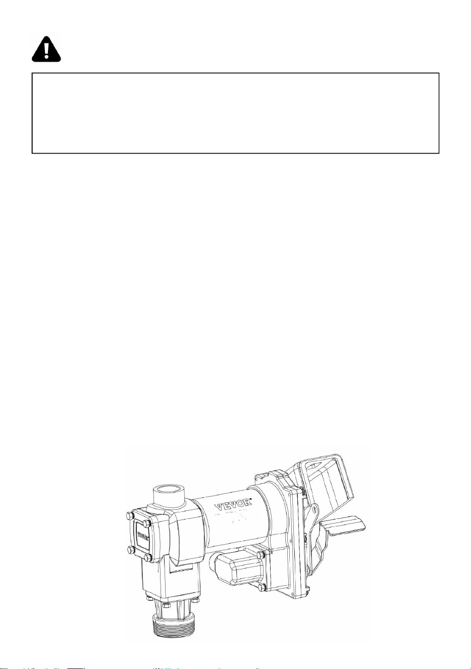
-
13
-
WARNING! Do not attempt to power the pump from vehicle wiring
smaller than 12 gage such as the cigarette lighter wire because these
thin wires could overheat and cause a fire.
gelijkstroom Bedrading (vervolg)
Voor Slippen Gemonteerd Tanks
19. Leid de elektrische draden naar de stroombron en ondersteun de
draden zo goed mogelijk.noodzakelijk en ze beschermen tegen
scherpe randen, hitte en alles Dat zou kunnen schade de draden.
20. Bevestig het ene uiteinde van de zekeringhouder aan de rode
pompdraad, zo dicht mogelijk bij de batterij/stroombron zo goed
mogelijk. Maak een solide elektrische verbinding met de positieve
aansluiting van de stroombron met de andereuiteinde van de
zekeringhouder. Maak een stevige verbinding met de zwarte pomp
draad naar de negatief terminal van de stroom bron.
21. Controleer alle verbindingen om er zeker van te zijn dat ze correct
zijn aangesloten. instructies en alle elektrische codes. Installeer de 4
0 ampère zekering (20 ampère samensmelten in 24 VDC installaties)
in de samensmelten houder. De installatie is nucompleet.
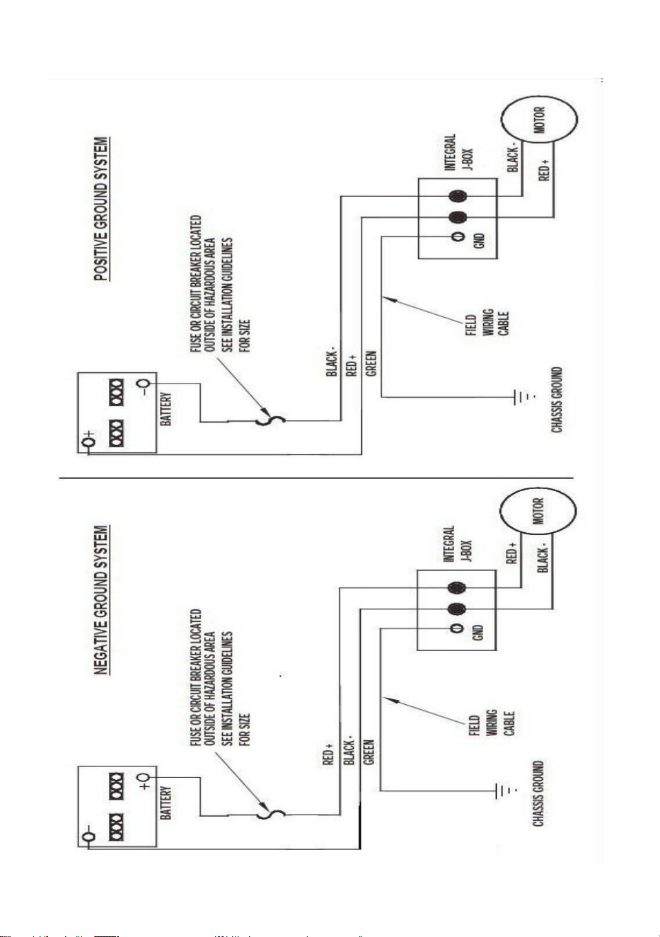
-
14
-
gelijkstroom Bedrading Diagram

-
15
-
WARNING! Always keep the nozzle in contact with the container
being filled during the filling process to minimize the possibility of static
electricity build up.
OPERATING INSTRUCTIONS
19.
Als Dus uitgerust, opnieuw instellen meter naar “0” (Doen niet
opnieuw instellen terwijl in gebruik zoals dit zullenoorzaak schade naar
de meter).
20.
Verwijderen afgeven mondstuk van mondstuk laars.
21.
Zet de schakelaar op de stand “AAN” om de pomp van stroom te
voorzien (figuur 1).4.Invoegen de afgeven sproeier in de houder naar zijn
gevuld.
23.
Bedien het mondstuk om vloeistof te doseren; laat het mondstuk
los wanneer de gewenste hoeveelheid vloeistof is bereikt.hoeveelheid
van vloeistof heeft geweest verstrekt.
“ON”positiong
Figure 1
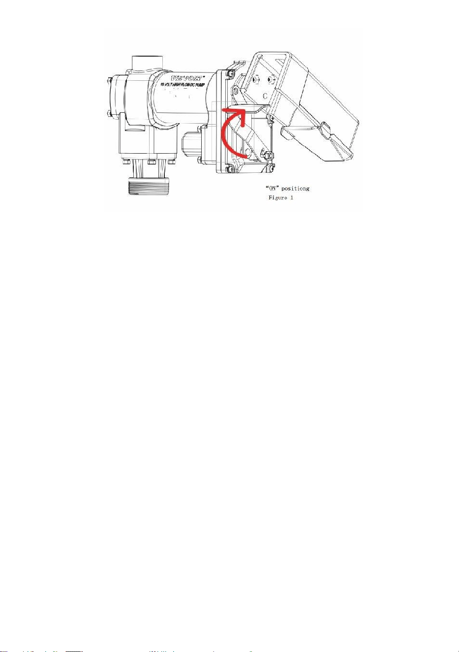
-
16
-
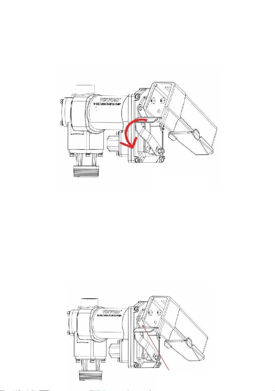
-
17
-
24. Beweging schakelaar hefboom naar de "UIT" positie (Figuur 2) naar
draai uit de pomp.
25. Verwijderen de afgeven mondstuk van de houder wezen gevuld En
winkel Hetin de sproeierhoes.
Hangslot
Jouw pomp mondstuk kan zijn op slot naar de pomp voor toegevoegd
beveiliging. Met de pomp gedraaid uit, En de mondstuk in de opgeslagen
positie, A hangslot kan zijn ingevoegd door de vergrendeling link En de
sproeier handvat.
De vergrendelingsschakel bevindt zich aan de sproeierzijde van de
pomp en kangedraaid naar binnen positie naar werk met A
verscheidenheid van sproeiers ( Afbeelding 3 ).
“OFF”positiong
Figure 2
locking Link
Figure 3

-
18
-

-
19
-
WARNING! DO NOT open or attempt to repair the motor on your
pump. Return it to the place of purchase for service. Opening the motor
case can compromise the integrity of the Explosion Proof construction
and will void any existing warranty and certification.
WARNING! Be certain all power to the pump is disconnected prior
to performing any service or maintenance.
TROUBLESHOOTING
De volgende handleiding voor probleemoplossing is bedoeld om
basisdiagnostiek te bieden assistentie in het geval dat u een abnormale
service van uw 20GMP ondervindtbrandstof overdracht product.

-
20
-
Symptoom
Oorza
ak
Gene
zing
Pomp wil
nietpriem.
1. Zuigleiding probleem.
Rekening voor lekken of obstakels in zuigen lijn.
2. Omzeilen ventiel open.
Verwijderen En inspecteren ventiel; moeten
beweging vrij & zijn
vrij van brokstukken.
3. Schoepen plakken.
Rekening schoepen En sleuven voor kerven,
bramen En dragen.
4. Excessief rotor of vaan
dragen.
Inspecteren rotor & schoepen voor excessief
dragen of
schade; vervangen als nodig.
5. Damp Slot.
Verklein de verticale en horizontale afstand
vanpomp naar vloeistof; verwijderen
automatisch mondstuk.
Laag capaciteit.
1. Excessief vuil in scherm.
Verwijderen En schoon scherm.
2. Zuigleiding probleem.
Controleer de aanzuigleiding op lekken of
beperkingen; het kan zijn datzijn te klein, te lang
of niet luchtdicht.
3. Omzeilen ventiel plakken.
Verwijderen En inspecteren ventiel; moeten
beweging vrij & zijn
vrij van brokstukken.
4. Uitlaat geblokkeerd.
Rekening pomp stopcontact, slang, sproeier &
filteren voor
verstopping.
5. Schoepen plakken.
Rekening schoepen En sleuven voor dragen.
6. Excessief rotor of vaan
dragen.
Inspecteren rotor & schoepen voor
excessief dragen ofschade; vervangen als
nodig.
7. Slang of mondstuk
schade.
Vervangen slang of mondstuk.
8. Ingeplugd filter.
Vervangen filter.
9. Laag vloeistofniveau
niveau.
Vullen tank.
Pomp
1. Onjuist spanning.
Rekening binnenkomend netspanning terwijl pomp
is
rennen.
2. Schoepen plakken.
Inspecteren schoepen En sleuven voor kerven,
bramen En dragen.

-
21
-
draait
langzaam.
3. Bedrading probleem.
Rekening voor loszittend verbindingen.
4. Motor probleem.
Opbrengst naar plaats van aankoop.

-
22
-
TROUBLESHOOTING (CONT’D)
Motor slaat af /
zekeringklappen
of thermisch
beschermheer
reizen
herhaaldelijk.
1. Omzeilen ventiel plakken.
Verwijderen En inspecteren ventiel; moeten
beweging vrij
& zijn vrij van brokstukken.
2. Laag spanning.
Rekening binnenkomend netspanning terwijl
pomp is
rennen.
3. Excessief rotor of slijtage van
de schoepen.
Rekening rotor & schoepen voor excessief
dragen of
schade.
4. Brokstukken in pomp holte.
Schoon brokstukken van pomp holte.
Motor
oververhit
raakt.
1. Pompen hoog viscositeit
vloeistoffen.
Deze vloeistoffen kan alleen zijn gepompt voor
kort
tijdsperiodes (minder dan 30 minuten
dienst)cyclus).
2. Verstopt scherm.
Verwijderen En schoon scherm.
3. Beperkt zuigen pijp.
Verwijderen En schoon pijp.
4. Motor mislukking.
Opbrengst naar plaats van aankoop.
5. Pomp rotorblokkering.
Schoon En rekening pomp rotor en schoepen.
Motor
Buiten
werking.
1. Nee stroom.
Rekening binnenkomend stroom.
2. Schakelaar mislukking.
Vervangen schakelaar .
3. Motor mislukking.
Opbrengst naar plaats van aankoop.
4. Thermisch beschermer
mislukking.
Opbrengst naar plaats van aankoop.
5. Onjuist/los bedrading.
Rekening bedrading.
Vloeistof lekkage.
1. Slechte o-ring pakking.
Rekening alle O-ring pakkingen.
2. Vies schacht zegel.
Schoon zegel & zegel holte.
3. Slechte schacht zegel.
Vervangen zegel.
4. Onverenigbaar vloeistof.
Refereren bevochtigd onderdelen lijst naar
vloeistof fabrikant.
5. Loszittend
bevestigingsmiddelen.
Vastdraaien bevestigingsmiddelen.
Pomp brommen
Maar
zullen niet
opereren.
1. Motor mislukking.
Opbrengst naar plaats van aankoop.
2. Gebroken rotor sleutel.
Verwijderen alle brokstukken & vervangen
sleutel.
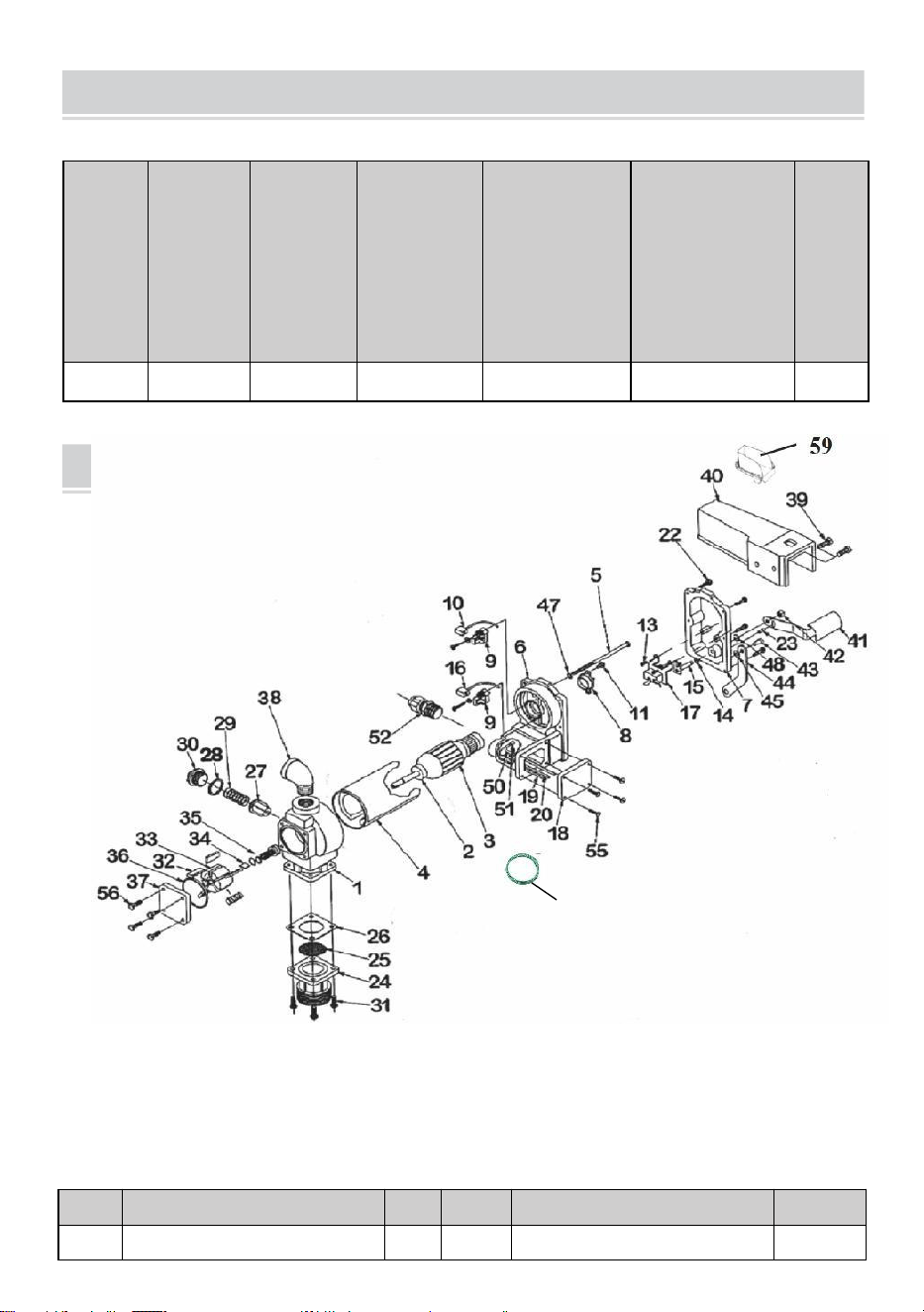
-
23
-
PARTS LIST
SECIFICATIONS
Model
Spanni
ng
Invoer
(W)
Stroomsn
elheid
(GPM-
numme
r)
Inlaatpijp
specificatie
( duim )
Uitlaatpijp
specificatie
( duim )
GW
(kg)
KEX-20
DC12V
400
20
1
1
11.28
REF#
BESCHRIJVING
OTY
REF#
BESCHRIJVING
OTY
1
POMPHUIS
1
34
ROTOR SLEUTEL
1
60

-
24
-
2
BAL HANDELSWIJZE
2
35
ROTOR OMSLAG
1

-
25
-
3
RMATUREASSEMBLAGE
1
36
ROTOR OMSLAG PAKKING
1
4
MOTOR
FRAME/MAGNETASSEMBLA
GE
1
37
AFDICHTINGSAMENSTELLIN
G
1
5
1/4-2×5THRU-BOUT
2
38
STAAL ELLEBOOG
1
6
MOTOR GIETEN MONTAGE
1
39
5/16-18×3/4HHCS
1
7
SCHAKELAAR BORD MET
BUS HING
1
40
MONDSTUK OMSLAG
2
8
THERMISCH BESCHERMER
1
41
SCHAKELAAR HEFBOOM
1
9
BORSTEL HOUDER MONTAGE
2
42
5/15×18LOVK MOER
1
10
NEGATIEF BORSTEL
MONTAGE
1
43
#14×S/8DRVE SCHROEF
1
11
#8-32×1/2TORX
1
44
VERGRENDELING LINK
1
12
-
45
1/4 LENTE WASMACHINE
1
13
#8-32×3/8 TORX
2
46
ECT SLOT WASMACHINE
1
14
5/16 LENTE WASMACHINE
1
47
-
15
SCHAKELAAR AS MONTAGE
1
48
5/16 BEHOUDEN RING
2
16
POSITIEVE
BORSTELMONTAGE
1
49
GROND DRAAD
1
17
LIJN SCHAKELAAR
1
50
-
18
KNOOPPUNT DOOS OMSLAG
1
51
#832×3/8GROND SCHROEF
1
19
NEGATIEF DRAAD LEIDING
1
52
KABEL VERBINDING
1
20
POSITIEF DRAAD LEIDING
1
53
-
-
21
-
54
-
-
22
10-24×3/4 TORX
6
55
10-24×.50TORX
4
23
5/32×1/2PIN
1
56
1/4-20×.5HHCS
4
24
INLAAT FLENS
1
57
-
-
25
SCHERM
1
58
-
-
26
INLAAT PAKKING
1
59
OLIE ONTVANGEN DOOS
1
27
OMLEIDING VENTIEL
1
60
Grond Draad
1
28
BIJZONDER VENTIEL
PAKKING
1
29
OMLEIDING LENTE
1
30
OMLEIDING GLB
1
31
1/4-20×3/4HHCS
1
32
VANE
4

-
26
-
33
ROTOR
5


-
28
-
Teknisk Stöd och E-garanti Certifikat www.vevor.com/support
BRÄNSLE ÖVERFÖRA PUMP ( Singel )
ÄGARE INSTALLATION,
DRIFT, OCH SÄKERHET MANUELL
MODELL: KEX-20
Vi fortsätta till vara engagerad till förse du verktyg med konkurrenskraftig pris.
"Spara hälften", "Halva priset" eller andra liknande uttryck som används av oss
representerar endast en uppskatta av besparingar du makt förmån från uppköp viss verktyg
med oss jämfört till de störretoppmärken och betyder inte nödvändigtvis att täcka alla
kategorier av verktyg som erbjuds av oss. Dupåminns vänligen om att kontrollera noggrant
när du gör en beställning hos oss om du gör det faktiskt spara hälften i jämförelse med bästa
större varumärken.

-
1
-
This is the original instruction, please read all manual instructions
carefully before operating. VEVOR reserves a clear interpretation of our
user manual. The appearance of the product shall be subject to the
product you received. Please forgive us that we won't inform you again if
there are any technology or software updates on our product.
FUEL TRANSFER PUMP
MODELL: KEX-20
Have product questions? Need technical support? Please feel free to
contact us:
Technical Support and E-Warranty Certificate
www.vevor.com/support
NEED HELP? CONTACT US!

-
2
-
SAFETY INFORMATION
WARNING! Electrical wiring should be performed ONLY by a
licensed electrician in compliance with local, state, and national
electrical code NEC/ANSI/ NFPA 70, NFPA 30, and NFPA 30A, as
appropriate to the intended use of the pump. Threaded rigid conduit,
sealed fittings, and conductor seal should be used where applicable.
The pump must be properly grounded. Improper installation or use of
this pump can result in serious bodily injury, or death!
VARNING! Till säkerställa säker och ordentligt drift av din utrustning,
det är viktigt att läsa och följa alla följande säkerhetsvarningar och
försiktighetsåtgärder. Felaktig installation eller användning av denna
produkt kan orsaka allvarlig kroppsligt skada eller död!
Rök ALDRIG nära pumpen, och använd ALDRIG pumpen nära
öppen låga när pumpning a brandfarlig vätska! Brand burk resultat!
Ett filter bör användas på pumpens utlopp för att säkerställa att inget
främmande material är överförs till de bränsle tank.
Gängad rör leder och anslutningar måste vara sluten med de
lämplig tätningsmedel eller tätningstejp för att minimera risken för
läckor.
Förrådstankar måste vara säkert förankrad för att förhindra
skiftande eller tippning när full eller tömma.
Till minimera statisk elektricitet bygga upp, använda endast statisk
tråd ledande slang vid pumpning av brandfarliga vätskor, och håll
påfyllningsmunstycket inne kontakta med de behållare varelse fylld
under de fyllning behandla.
Pumpmotorn är utrustad med termiskt överbelastningsskydd;
omöverhettad, kommer motorn att stängas av för att förhindra
skador på lindningar.

-
3
-
INSTALLATION
WARNING! This product shall not be used to transfer fluids into
any type of aircraft.
WARNING! This product is not suited for use with fluids intended
for human consumption or fluids containing water.
20GMP bränsleöverföringspump är designad för att monteras på en
glidtank med hjälp avden gängade inloppsflänsen som medföljer pumpen.
Din pump har en inbyggd bypassventil för att återcirkulera vätskan när
pumpen är igång med de munstycke stängd.
WARNING! This product is not suited for use with fluids intended
for human consumption or fluids containing water.
CAUTION! Do not use additional check valves or foot valves
unless they have a proper pressure relief valve built into them. Note that
additional check valves will reduce rate of flow.

-
4
-
CAUTION! A pressure retaining fill cap can be used to reduce fuel
loss through evaporation, but note that it will reduce the flow rate.
CAUTION! Threaded pipe joints and connections must be sealed
with the appropriate sealant or sealant tape to prevent the possibility of
leaks.
WARNING! 20GMP fuel transfer pumps are designed for use with
stationary and mobile tank applications. While DC powered units are
excellent choice for mobile applications, anchoring the tank to which the
pump is mounted is paramount to ensure no movement in transit.
Failure to secure the tank to the vehicle can cause uncontrolled
movement, resulting in damage, injury, and potential fire.
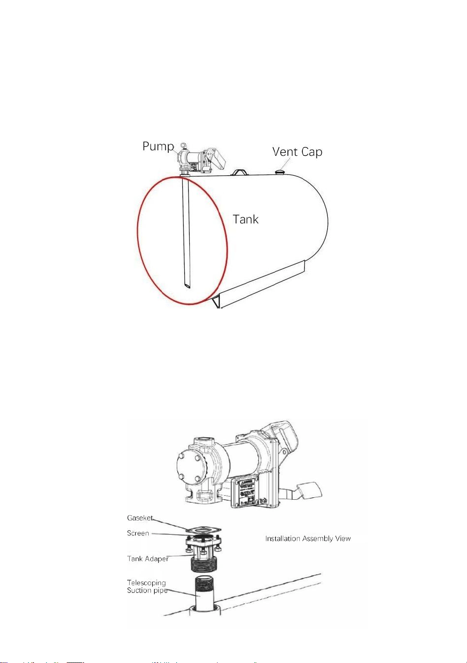
-
5
-
Typisk Sladd Tank Installation
De pump fästen till de propp av a sladd tank av sätt av de inlopp fläns. De
sugröret träs in i botten av inloppsflänsen och måste sträcka sig tillen
längd som placerar den minst 3” från botten av tanken. Skidan tank skall
vara utrustad med en ventilera lock.
Material:
1” teleskopiskt sugrör förlängt till en längd som sträcker sig till inom 3”
från tankens botten när den skruvas in i tankadapternmed
tankadaptern skruvad i tankflänsen (se SKIDTANK INSTALLATION
diagram).
Gängad rör gemensam tätningsmedel lämplig för ansökan.

-
6
-
Installation Förfarande:
22. Tråd de 1” rör till de tank adapter. Täta trådar flytande stram med
lämplig tätningsmedel. (Figur 1)
Typisk Sladd Tank Installation (forts.)
23. Skruva in inloppsflänsen (med sugrör) i tankproppen; tätatrådar
flytande stram med lämplig tråd tätningsmedel (Figur 2).

-
7
-
ELECTRICAL WIRING
24. Montera pumpen på adaptern; se till att tätningen och skärmen är
installerat som visas. (Figur 3).
CAUTION! DC powered pumps are designed to operate on either
12 or 24 VDC (depending on model). Where applicable, use the
supplied battery cable to supply power to the pump from a 12 or 24
VDC battery. A 40 amp fuse (20 amp fuse on 24 VDC motors) should be
installed on the battery cable to protect the wire in case of electrical
short.

-
8
-
CAUTION! Voltage drop in wiring varies depending on the
distance from the battery to the pump and the gauge of the wire used. If
the distance is greater than 20’, refer to national, international, or local
electrical codes to ensure the wire is of the correct size for this
application.
Instruktioner Före Förfarande Med DC-ledningar
Pumpen måste vara elektriskt ansluten till matningstanken eller
fordonsramen. För att elektriskt binda pumpen, ta bort den gröna
fästskruven bredvid kopplingsdosans lock. Sätt in denna skruv genom
öglan av möblerad grön bindning tråd montering och fäst igen det säkert till
de pump. De andra avslutaav de tråd är till vara avskalad av isolering och
de bar tråd säkert bundentill de fordon / trailer ram eller sladd tank.
WARNING! Do not connect the positive or negative power to the
green screw or wire as this could cause a fire.
Kabeldragning Instruktioner
43. Ta bort pumps elektrisk korsning låda täcka och räta de 2
ledningar till gör de avskalade trådändarna tillgängliga
utanför korsning låda.
44. Skruva möblerad kabel kontakt till NPT* rörledning öppning i pump
korsning låda.
45. Remsa 6 tum av de yttre beläggning från en avsluta av de
möblerad

-
9
-
elektrisk kabel varelse försiktig inte till skada de svart och röd tråd
isolering.
46. Lossa kabel kontakt mutter och passera de avskalad avsluta av de
möblerad kabel genom de kabel kontakt. Spänna de kabel kontakt
mutter.
47. S t r i sid 1⁄2
i nc h o f t h e i nsu l a t i o n f r o m t h e slut s o f t h e
r e d en d b l ac k cab l e ledningar. Använd de medföljande
trådmuttrarna och anslut dessa trådar till pumpen ledningar
motsvarande de färger. Vara säker inga bar tråd är utsatt.
48. Vik in kablarna i kopplingsdosan och sätt tillbaka locket och se till att
packningenär på plats. Se till att alla skruvar sitter så att det inte finns
något utrymme mellan de täcka och den korsning låda.
Kabeldragning Till A Fordon Elektrisk System
29. För de elektriska ledningarna till källan till fordonets kraftsystem,
stödja ledningarna vid behov och skydda dem från vassa kanter,
värme, och allt det där kunde skada de ledningar.
30. För att avgöra om fordonets elektriska system är negativt (-) eller
positivt (+) jord, kontrollera batterimärkningen på terminalen som är
ansluten till fordonsramen eller motorblocket. Den röda ledningen från
pumpen kommer anslut till den positiva batteripolen så kommer den
svarta ledningen från pumpen ansluta till negativt batteri posta.
31. Fäst ena änden av säkringshållaren i änden av den ojordade
ledningen. Göra a fast elektrisk förbindelse med de andra avsluta av
de säkring hållaretill den ojordade sidan av batteriet, så nära batteriet
som möjlig. Göra a fast elektrisk förbindelse till de grundad sida av de
batteriet med den återstående kabeln. Batteripolen eller änden av
batteri kabel är rekommenderad.
32. Kontrollera alla anslutningar till göra säker de är ansluten per
instruktioner och alla elektriska koder. Installera 4 0 amp säkringen
(20 amp säkring i 24 VDC installationer) i säkringshållaren.
Installationen är nukomplett.
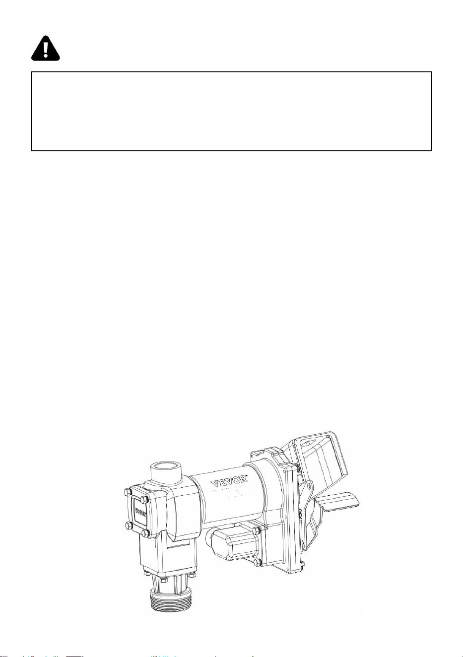
-
10
-
WARNING! Do not attempt to power the pump from vehicle wiring
smaller than 12 gage such as the cigarette lighter wire because these
thin wires could overheat and cause a fire.
DC Kabeldragning (forts.)
För Sladd Monterad Tankar
22. För de elektriska ledningarna till strömkällan, stödja ledningarna som
nödvändigt och skydda dem från vassa kanter, värme och allt möjligt
att kunde skada de ledningar.
23. Fäst ena änden av säkringshållaren till den röda pumpkabeln så
nära batteriet/strömkällan som möjligt. Gör en solid elektrisk
anslutning till den positiva polen på strömkällan med den andra
änden av säkringshållaren. Gör en solid anslutning med den svarta
pumpen tråd till de negativ terminal av de driva källa.
24. Kontrollera alla anslutningar för att säkerställa att de är anslutna pr
instruktioner och alla elektriska koder. Installera 4 0 amp säkringen
(20 amp säkring i 24 VDC installationer) i de säkring hållare. De
installation är nukomplett.
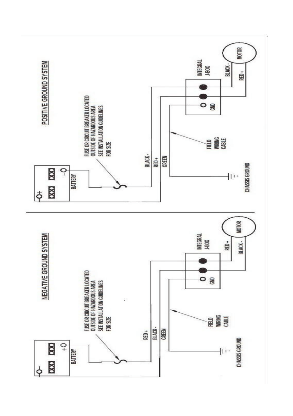
-
11
-
DC Kabeldragning Diagram
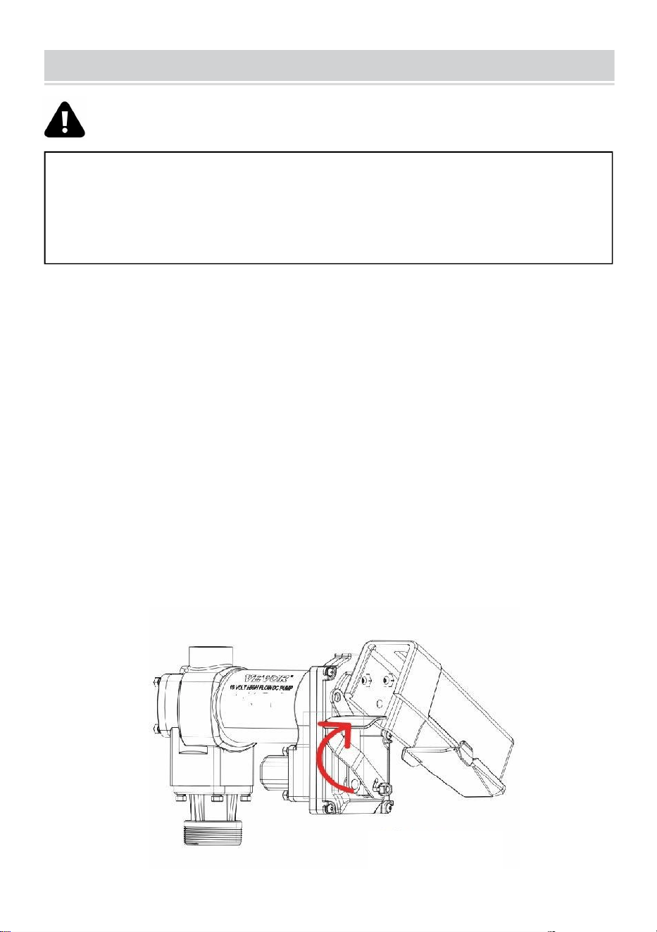
-
12
-
WARNING! Always keep the nozzle in contact with the container
being filled during the filling process to minimize the possibility of static
electricity build up.
OPERATING INSTRUCTIONS
22.
Om så utrustade, återställa meter till "0" (do inte återställa medan i
använda som detta viljaorsaka skada till de meter).
23. Ta bort dispensering munstycke från munstycke känga.
24. Flytta omkopplarspaken till "ON"-läget för att driva pumpen (figur 1).
4.Infoga de dispensering munstycket in i de behållare till vara fylld.
26. Använd munstycket för att dispensera vätska; släpp munstycket
när så önskasbelopp av vätska har varit dispenseras.
“ON”positiong
Figure 1
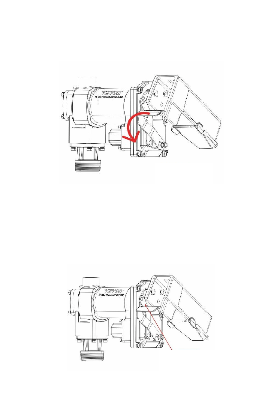
-
13
-
27. Flytta växla spak till de "AV" placera (Figur 2) till sväng av de pump.
28.
Ta bort de dispensering munstycke från de behållare varelse fylld och
lagra deti de munstycksstövel.
Hänglås
Din pump munstycke burk vara hänglåst till de pump för lagt till säkerhet.
Medde pump vände av, och de munstycke i de lagras placera, a hänglås
burk varainsatt genom låsning länk och de munstyckshandtag.
Låslänken är placerad på munstyckssidan av pumpen, och kan vara
vriden till placera till arbete med a variation av munstycken ( bild 3 ).
“OFF”positiong
Figure 2
locking Link
Figure 3

-
14
-
WARNING! DO NOT open or attempt to repair the motor on your
pump. Return it to the place of purchase for service. Opening the motor
case can compromise the integrity of the Explosion Proof construction
and will void any existing warranty and certification.
WARNING! Be certain all power to the pump is disconnected prior
to performing any service or maintenance.
TROUBLESHOOTING
Följande felsökningsguide tillhandahålls för att erbjuda grundläggande
diagnostik hjälp om du stöter på onormal service från din 20GMPbränsle
överföra produkt.

-
15
-
Symptom
Orsak
a
Bota
Pumpen
gör det inte
främsta.
1. Sugledning problem.
Kontrollera för läckor eller hinder i sugning linje.
2. Gå förbi ventil öppna.
Ta bort och inspektera ventil; måste flytta fritt &
vara
gratis av skräp.
3. Vanes fastnar.
Kontrollera skovlar och slots för nicks, grader och
bära.
4. Överdriven rotor eller
vindflöjel
bära.
Inspektera rotor & skovlar för överdrivet bära eller
skada; ersätta om nödvändig.
5. Ånga Låsa.
Minska vertikalt och horisontellt avstånd från
pump till flytande; ta bort automatisk
munstycke.
Låg kapacitet.
1. Överdriven smuts i
skärm.
Ta bort och rena skärm.
2. Sugledning problem.
Kontrollera sugledningen för läckor eller
begränsningar; det kanskevara för små, för lång
eller inte lufttät.
3. Gå förbi ventil fastnar.
Ta bort och inspektera ventil; måste flytta fritt &
vara
gratis av skräp.
4. Utlopp blockerad.
Kontrollera pump utlopp, slang, munstycke & filter
för
blockering.
5. Vanes fastnar.
Kontrollera skovlar och slots för bära.
6. Överdriven rotor eller
vindflöjelbära.
Inspektera rotor & skovlar för överdrivet
bära ellerskada; ersätta om nödvändig.
7. Slang eller munstycke
skada.
Ersätta slang eller munstycke.
8. Pluggad filtrera.
Ersätta filtrera.
9. Låg vätska nivå.
Fylla tank.
Pumpen
går
1. Felaktig spänning.
Kontrollera inkommande linjespänning medan
pumpen är
spring.
2. Vanes fastnar.
Inspektera skovlar och slots för nicks, grader och
bära.
3. Kabeldragning problem.
Kontrollera för lösa anslutningar.

-
16
-
långsamt.
4. Motor problem.
Återvända till plats av köpa.

-
17
-
TROUBLESHOOTING (CONT’D)
Motor
stannar/säkring
slag eller
termiska
skyddsresor
upprepat.
1. Gå förbi ventil fastnar.
Ta bort och inspektera ventil; måste flytta fritt
& vara fri från skräp.
2. Låg spänning.
Kontrollera inkommande linjespänning medan
pumpen är
spring.
3. Överdriven rotor eller
skovelslitage.
Kontrollera rotor & skovlar för överdrivet bära
eller
skada.
4. Skräp i pump hålighet.
Rena skräp från pump hålighet.
Motor
överhettas
.
1. Pumpning hög viskositet
vätskor.
Dessa vätskor burk endast vara pumpas för
kort
tidsperioder (mindre än 30 minuters
tjänstgöringcykel).
2. Tilltäppt skärm.
Ta bort och rena skärm.
3. Begränsad sugning rör.
Ta bort och rena rör.
4. Motor fel.
Återvända till plats av köpa.
5. Pump rotorlåsning.
Rena och kontrollera pump rotor och skovlar.
Motor
Verkningslö
s.
1. Inga driva.
Kontrollera inkommande driva.
2. Växla fel.
Ersätta växla .
3. Motor fel.
Återvända till plats av köpa.
4. Termisk beskyddare fel.
Återvända till plats av köpa.
5. Felaktig/lös ledningar.
Kontrollera ledningar.
Vätska läckage.
1. Dålig o-ring packning.
Kontrollera alla o-ring packningar.
2. Smutsig axel täta.
Rena täta & täta hålighet.
3. Dåligt skaft täta.
Ersätta täta.
4. Oförenlig vätska.
Hänvisa blött delar lista till vätska tillverkare.
5. Lösa fästelement.
Spänna fästelement.
Pump brummar
men
vilja inte fungera.
1. Motor fel.
Återvända till plats av köpa.
2. Bruten rotor nyckel.
Ta bort alla skräp & ersätta nyckel.
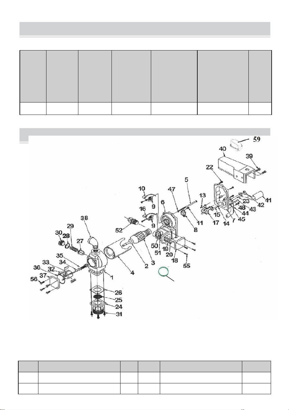
-
18
-
PARTS LIST
SECIFICATIONS
Modell
Spänni
ng
Ingång
(W)
Flödesha
stighet
(GPM)
Insugnings
rör
specifikation
( tum )
Utloppsrör
specifikation
( tum )
GW
(kg)
KEX-20
DC12V
400
20
1
1
11.28
REF#
BESKRIVNING
OTY
REF#
BESKRIVNING
OTY
1
PUMPHÅLLNING
1
34
ROTOR NYCKEL
1
2
BOLL LAGER
2
35
ROTOR TÄCKA
1
60

-
19
-
3
RMATURMONTERING
1
36
ROTOR TÄCKA PACKNING
1
4
MOTOR
RAM/MAGNETMONTERING
1
37
TÄTMONTERING
1
5
1/4-2×5GENOMBULT
2
38
STÅL ARMBÅGE
1
6
MOTOR GJUTNING
MONTERING
1
39
5/16-18×3/4HHCS
1
7
VÄXLA TALLRIK MED BUSS
HING
1
40
MUNSTYCKE TÄCKA
2
8
TERMISK BESKYDDARE
1
41
VÄXLA SPAK
1
9
BORSTA HÅLLARE
MONTERING
2
42
5/15×18LOVK MUTTER
1
10
NEGATIV BORSTA
MONTERING
1
43
#14×S/8DRVE SKRUVA
1
11
#8-32×1/2TORX
1
44
LÅSNING LÄNK
1
12
-
45
1/4 FJÄDRA BRUCKOR
1
13
#8-32×3/8 TORX
2
46
ECT LÅSA BRUCKOR
1
14
16/5 FJÄDRA BRUCKOR
1
47
-
15
VÄXLA AXELMONTERING
1
48
16/5 BEHÅLL RINGA
2
16
POSITIVBORSTMONTERING
1
49
JORD TRÅD
1
17
LINJE VÄXLA
1
50
-
18
KORSNING LÅDA TÄCKA
1
51
#832×3/8GROUND SKRUVA
1
19
NEGATIV TRÅD LEDA
1
52
KABEL KONTAKT
1
20
POSITIV TRÅD LEDA
1
53
-
-
21
-
54
-
-
22
10-24×3/4 TORX
6
55
10-24×.50TORX
4
23
5/32×1/2PIN
1
56
1/4-20×.5HHCS
4
24
INLOPP FLÄNS
1
57
-
-
25
SKÄRM
1
58
-
-
26
INLOPP PACKNING
1
59
OLJA MOTTAGANDE LÅDA
1
27
GÅ FÖRBI VENTIL
1
60
Jord Tråd
1
28
FÖRGÅNG VENTIL PACKNING
1
29
GÅ FÖRBI FJÄDRA
1
30
GÅ FÖRBI LOCK
1
31
1/4-20×3/4HHCS
1
32
VINDFLÖJEL
4
33
ROTOR
5