
Technical Support and E-Warranty Certificate
www.vevor.com/support
AC-DC Rectifier/Charger for RV
Instruction Manual
Model:GS800RVP-55
We continue to be committed to provide you tools with competitive price.
"Save Half", "Half Price" or any other similar expressions used by us only represents an
estimate of savings you might benefit from buying certain tools with us compared to the major
top brands and does not necessarily mean to cover all categories of tools offered by us. You
are kindly reminded to verify carefully when you are placing an order with us if you are
actually saving half in comparison with the top major brands.

- 1 -
MODEL:GS800RVP-55
Have product questions? Need technical support? Please feel free to
contact us:
Technical Support and E-Warranty Certificate
www.vevor.com/support
NEED HELP? CONTACT US!
This is the original instruction, please read all manual instructions
carefully before operating. VEVOR reserves a clear interpretation of our
user manual. The appearance of the product shall be subject to the
product you received. Please forgive us that we won't inform you again if
there are any technology or software updates on our product.
AC-DC Rectifier /
Charger for RV
- 2 -
Warning-To reduce the risk of injury, user must read instructions
manual carefully.
This device complies with Part 15 of the FCC Rules. Operation is
subject to the following two conditions:(1)This device may not cause
harmful interference, and (2)this device must accept any interference
received, including interference that may cause undesired operation.
This product is subject to the provision of European Directive
2012/19/EC. The symbol showing a wheelie bin crossed through
indicates that the product requires separate refuse collection in the
European Union. This applies to the product and all accessories
marked with this symbol. Products marked as such may not be
discarded with normal domestic waste, but must be taken to a
collection point for recycling electrical and electronic devices
SAFETY WARNINGS
FOR YOUR SAFETY, READ ALL INSTRUCTIONS BEFORE
INSTALLATION AND OPERATION.
INSTALLER:PROVIDE THESE INSTRUCTIONS TO THE END USER OR
CONSUME.
CONSUMER:KEEP THESE INSTRUCTIONS FOR FUTURE REFERENCE.
NOTICE:PRODUCTS ARE NOT TO BE USED NOR ARE WARRANTED IN
AEROSPACE, MEDICAL OR LIFE SAFETY APPLICATIONS.
WARNING
–
AVOID PERSONAL INJURY OR PRODUCT DAMAGE.
120 VAC IS PRESENT. THIS CONVERTER/CHARGER IS DESIGNED TO
CONVERT 120 VAC TO 12 VDC. IT ALSO PROVIDES LOW VOLTAGE
POWER FOR CHARGING ON-BOARD 12 VDC BATTERIES. THE
CONVERTER/CHARGER IS A “SWITCH MODE”TYPE AND IS DESIGNED
TO BE MAINTENANCE-FREE WITH NO USER SERVICEABLE
COMPONENTS. THE CONVERTER/CHARGER POWER OUTPUT I
“CURRENT LIMITING”BY DESIGN.

- 3 -
NEVER STORE ELECTRICAL DEVICES IN COMPARTMENTS WHERE
FLAMMABLE LIQUIDS (SUCH AS GASOLINE) EXIST. DO NOT
MOUNT/INSTALL UNIT IN COMPARTMENTS DESIGNED FOR STORAGE OF
BATTERIES OF FLAMMABLE LIQUIDS.
INSTALLATION INSTRUCTIONS
The AC-DC converter/charger has three modes: acid battery and lithium
battery charging and fixed output.
1.Disconnect the battery POS (+) wire at the battery end before connecting
this Converter/Charger to any vehicle/device wiring
2.The installation location can be located on any internal (unaffected by
direct weather) surface. The selected location must be accessible after
the following hours Installation. When installed inside a cabinet, the
cabinet must be large enough to dissipate hot air. Make sure there is at
least 1 inch (1 inch) of free air space at each end of the unit so that
cooling air can pass through the device normally. Avoid contaminants
such as peripheral dirt, metal particles, or moisture.
3.Flanges with holes are provided for ease of mounting using standard
fasteners. Confirm that the surface that the converter is mounted to is
solid and will hold the weight (6 lbs) during vehicle operation.
4.120 VAC receptacle needs to be located within 36 inches of the
Converter/Charger to supply power. Electrical consideration should also
be given to mounting near the locations of the batteries and the 12-volt
DC distribution panel.
5.Be sure to tighten all connections securely. A loose connection can
quickly cause terminals and wires to overheat. Review unit labels for
recommended terminal torque values.
6.The fan won't run all the time. The fan is temperature-controlled and
operates only when needed.
7.Once plugged in, never leave the device unattended.
8.All Products must be installed by a certified electrician.

- 4 -
WARNING :Avoid Possible Injury or Death.
120 VAC Connection: First confirm that the 120 VAC power source AC
circuit breaker(s) are in the off position. DO NOT turn-on AC circuit
breakers until installation is complete.
Using an 8 AWG minimum size copper wire, attach from the
vehicle/device chassis to the Converter/Charger Bonding Lug. Using the
attached power cord on the Converter/Charger, connect firmly to the 120
V AC receptacle.
12 VDC Wiring-It is important to use the correct wire gauge. Use a
minimum of 8 AWG size copper wire.
(1)The terminal marked + or POS is for the RV 12VDC positive connection.
(2)The terminal marked - or NEG is for the RV12VDC negative connection.
(3)The12VDC output wiring does not require over-current protection
because the Converter/ Charger limits current output. However, all
electrical connections need to comply with the appropriate NEC code.
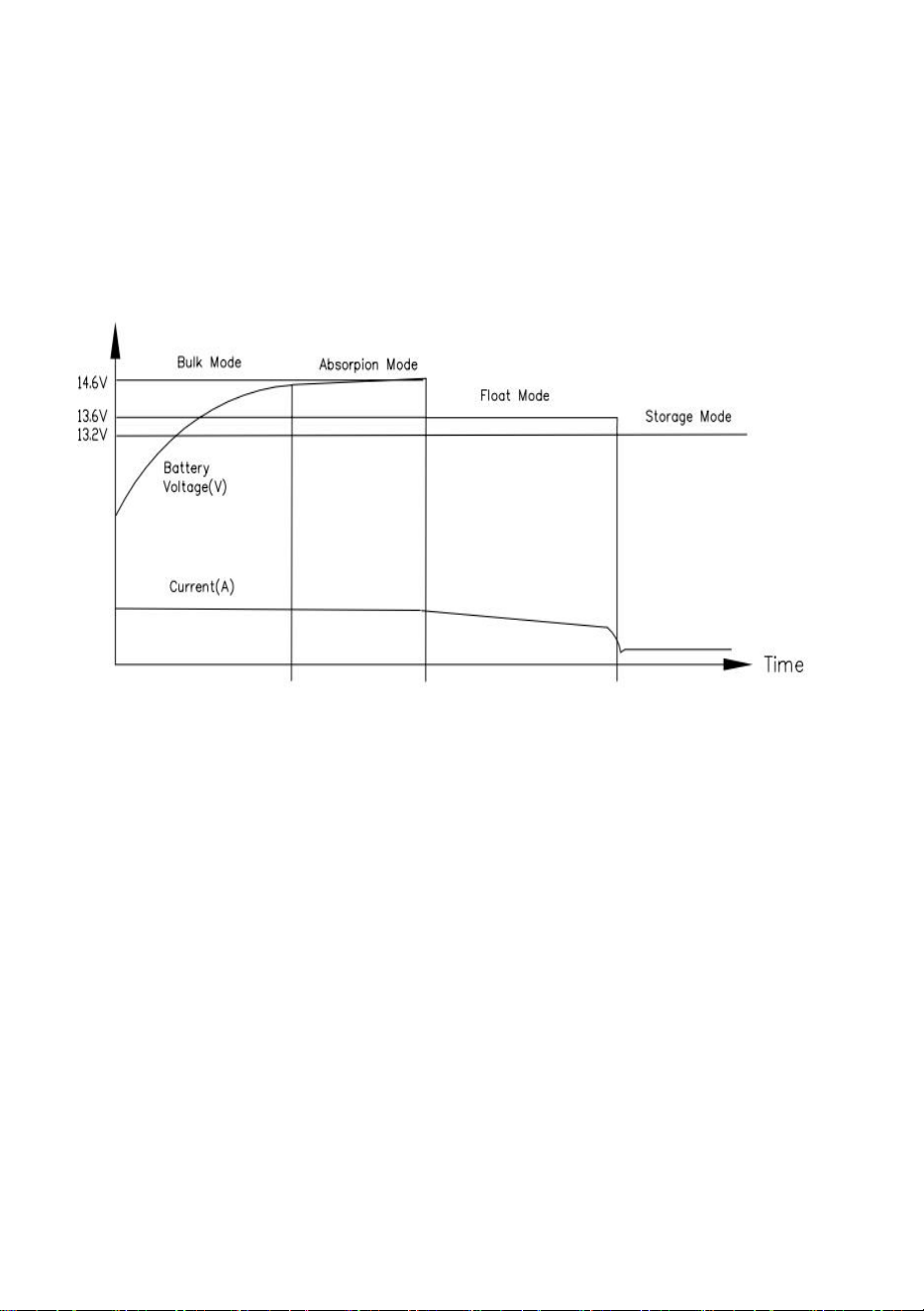
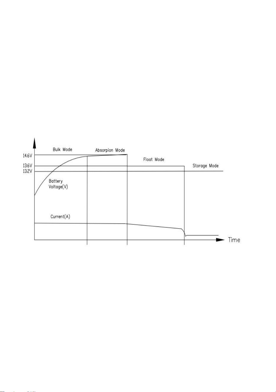
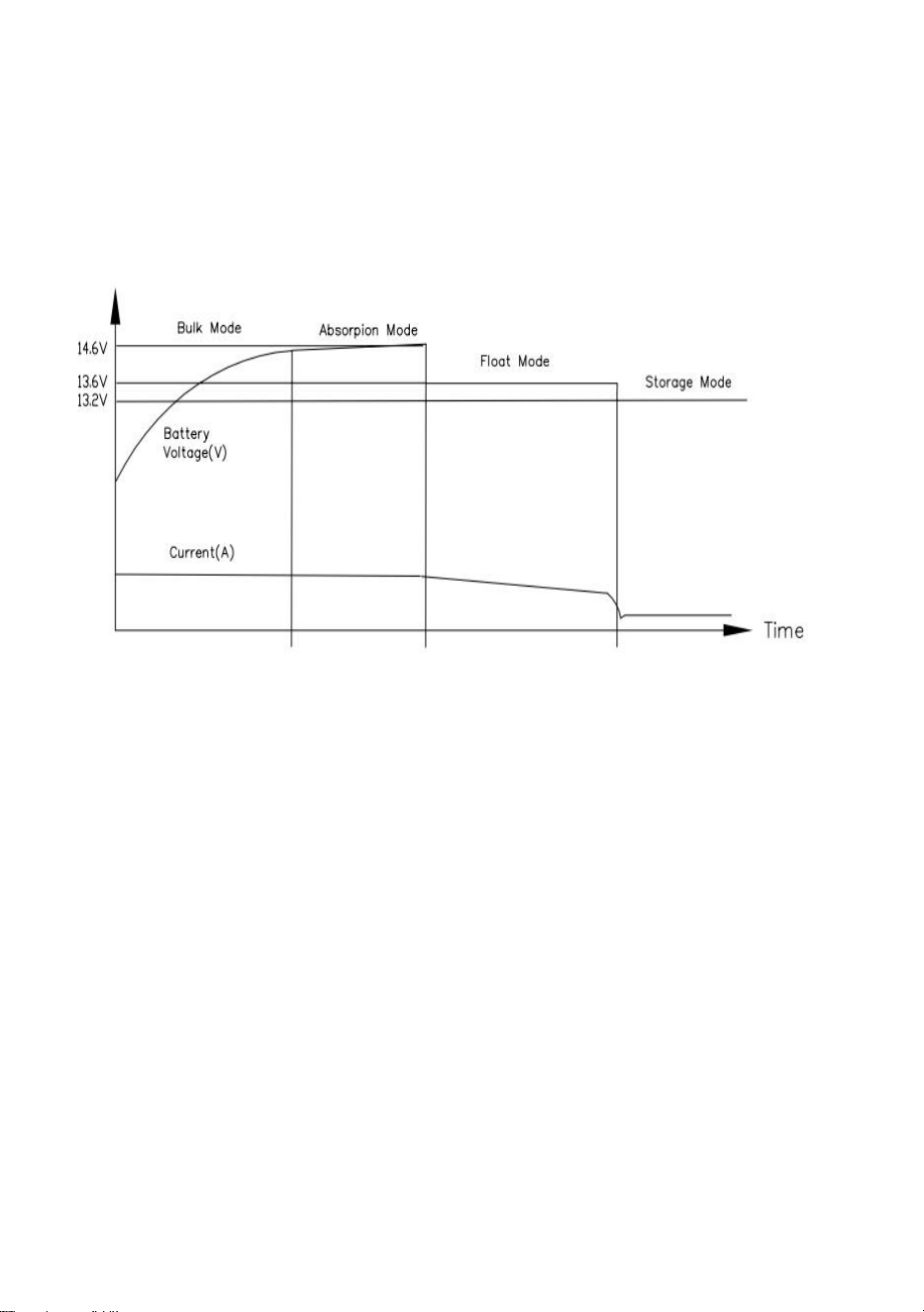
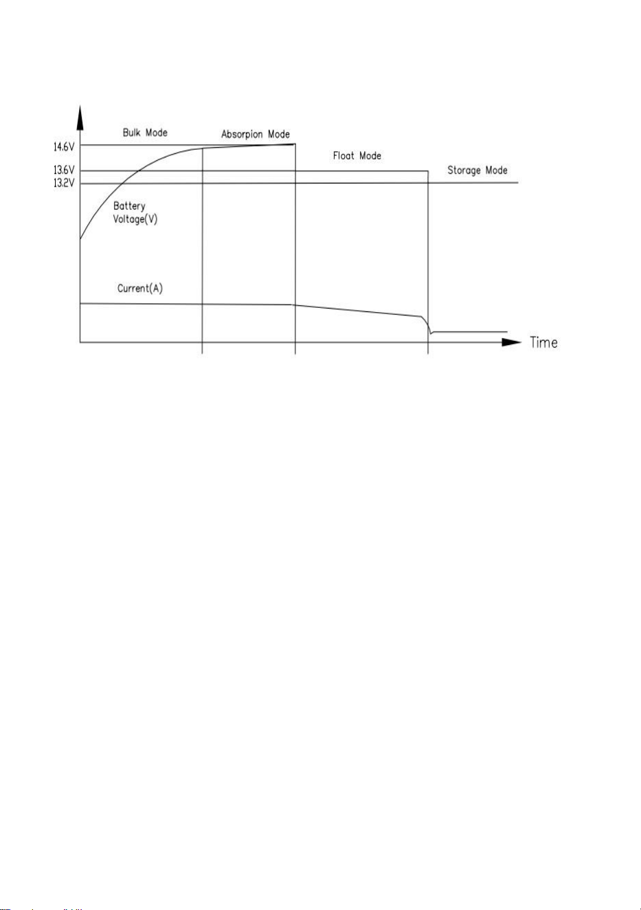
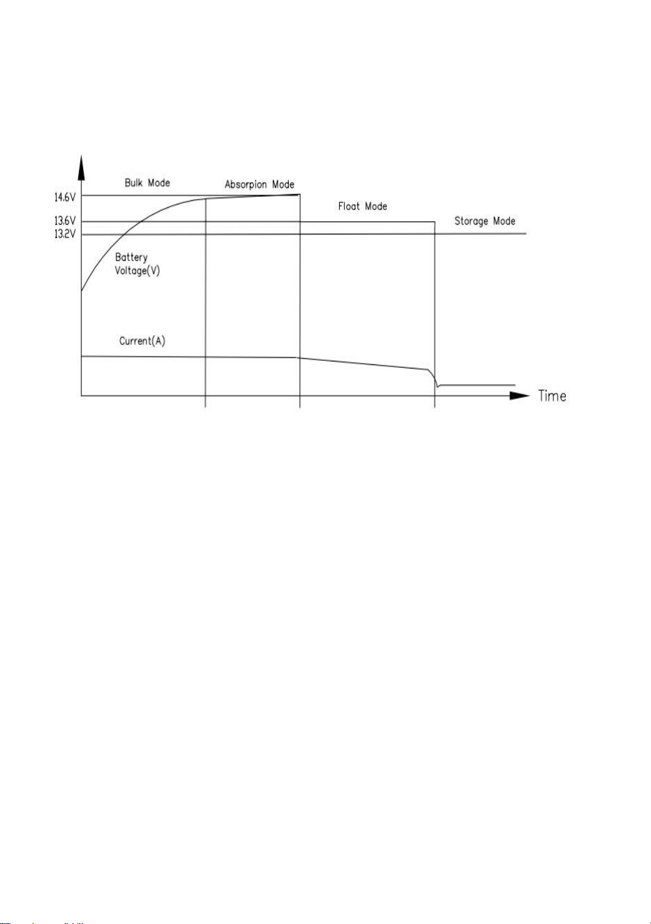
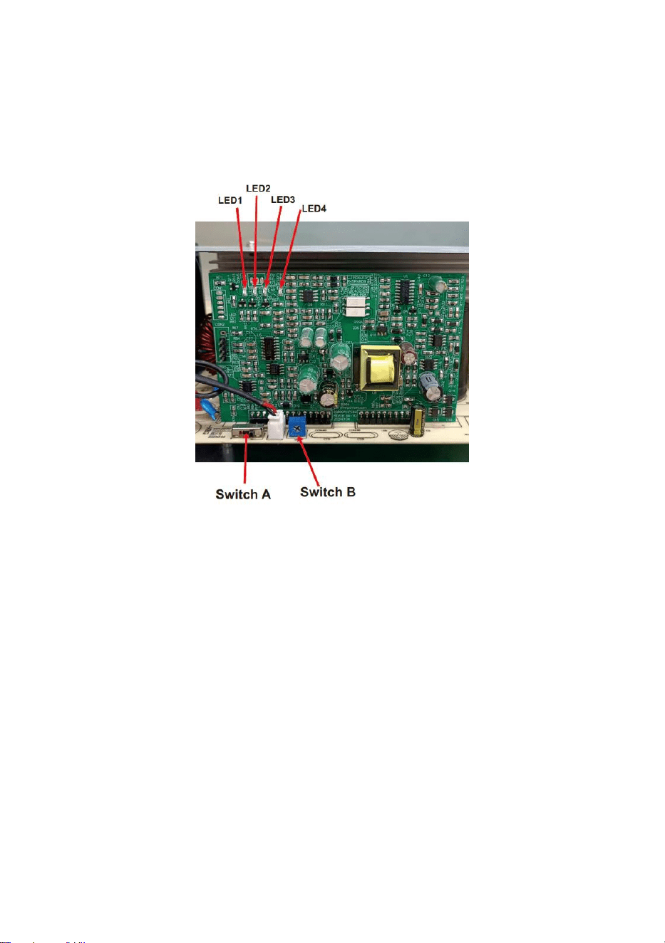
9.Lead-acid battery mode:
Enter this mode LED1 lights up green.This mode provides an
automatic charging system through four modes.(Figure 1).
(1)Constant current fast charging (Bulk Mode), so that the power is
exhausted and quickly restore the full voltage, LED1 is bright green,
LED4 is bright red.
(2)When the battery voltage reaches about 14.6V, it enters the constant
voltage charging mode (Absorpion Mode) at a safe rate to extend the life
of the battery and power supply. LED1 Green LED4 Red.
(3)When the charging current is less than 15% of the maximum output
current or when the charger has been charged for 4 hours, whichever
comes first, the charger will enter Bulk Mode. LED1 is green. The
charging voltage is approximately 13.6 V. If the charging current exceeds
50% of the maximum output current for more than 30 seconds, the
charger will re-enter Bulk mode and begin a new charging cycle. If the
charger remains in Absorb mode for 48 hours, it will enter Storage mode.
Translated with (free version).
- 5 -
(4)Trickle charging, which is used to keep the battery fresh ("storage")
during periods of load inactivity. The charger automatically changes
modes to accommodate changes in conditions. LED1 is green, and the
charging voltage is about 13.2V, and the voltage may vary depending on
the battery. If the charging current exceeds 50% of the maximum output
current for more than 30 seconds, the charger will re-enter constant
current charging and start a new charging cycle.
Figure 1
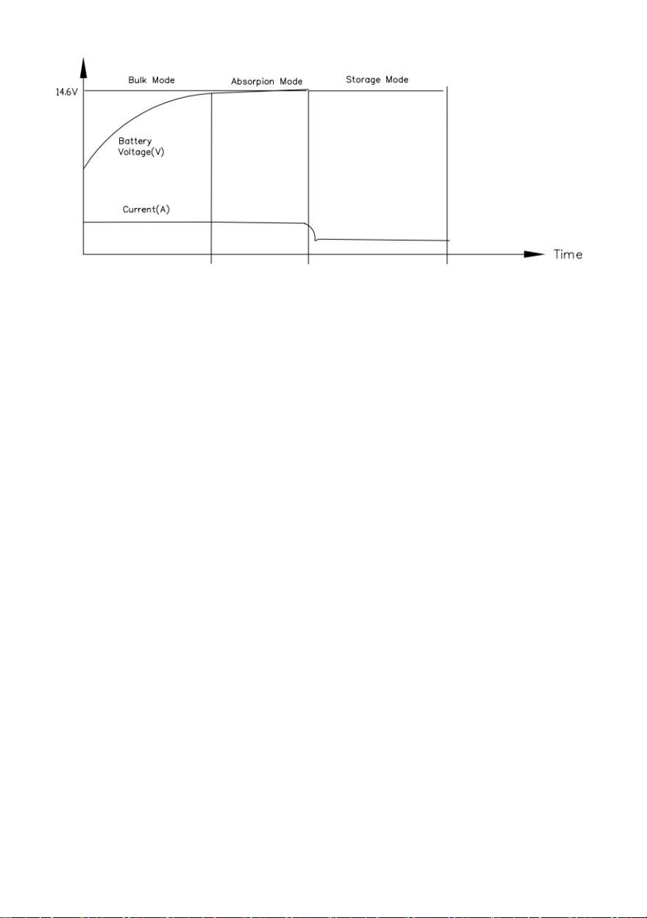
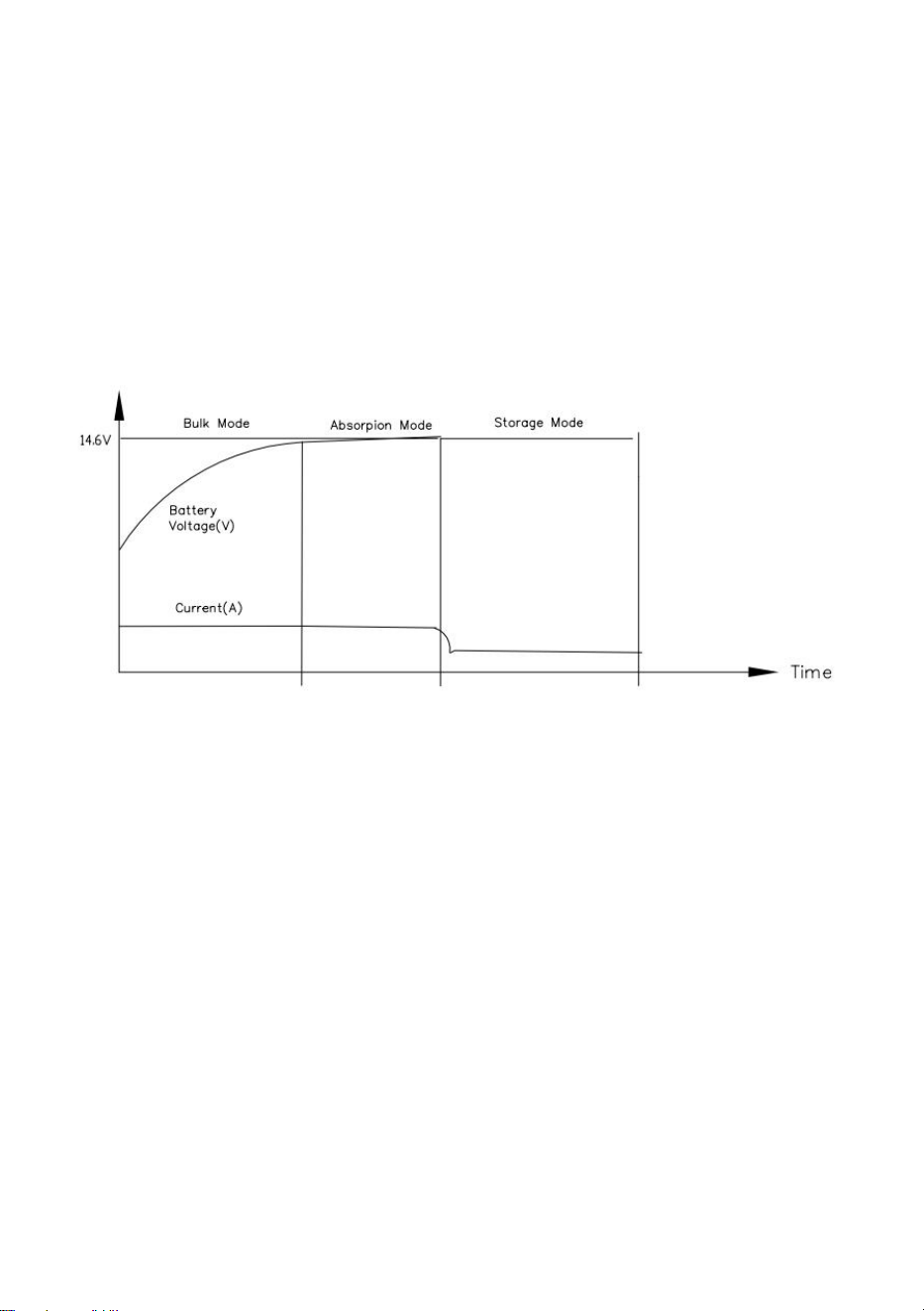
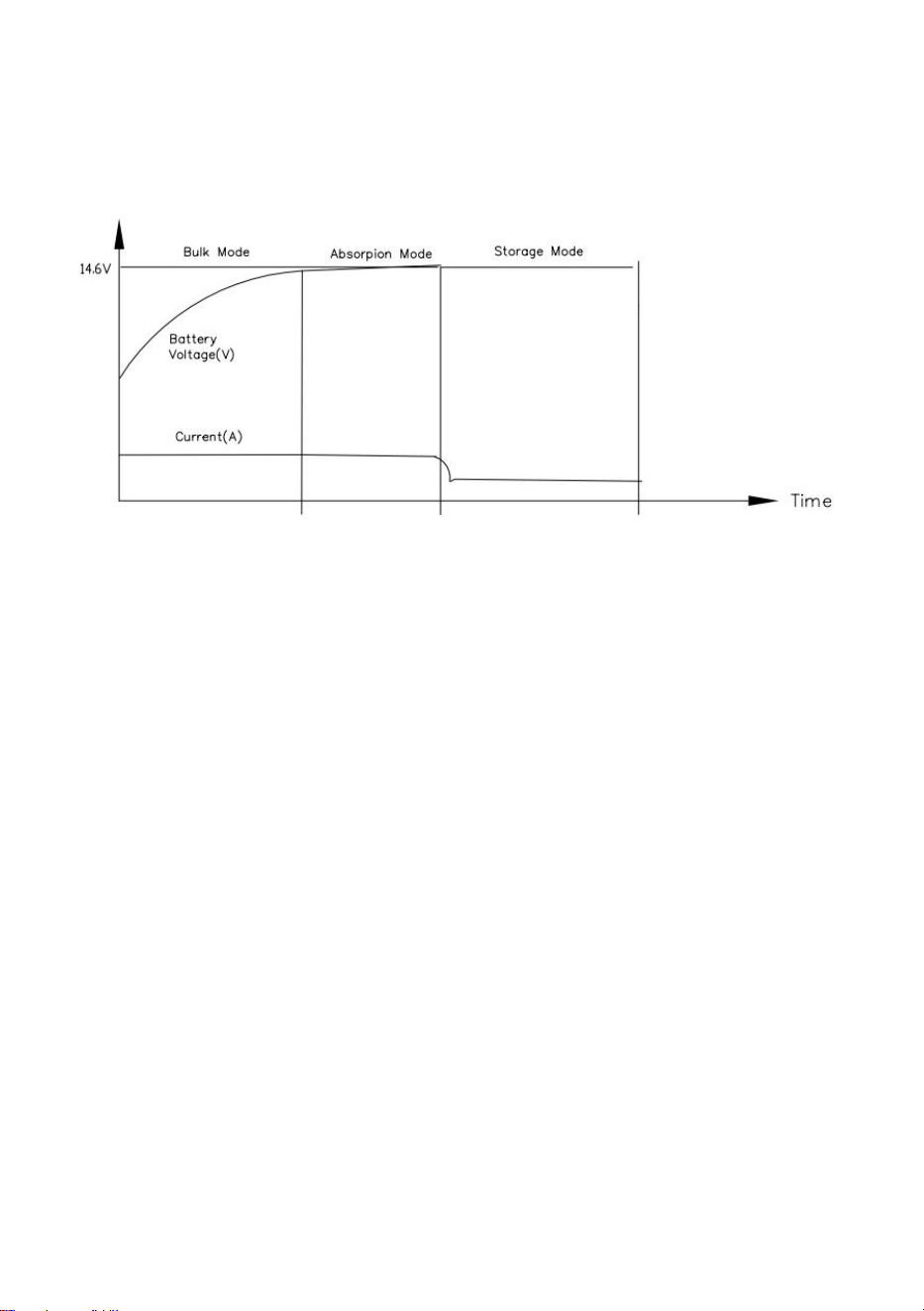
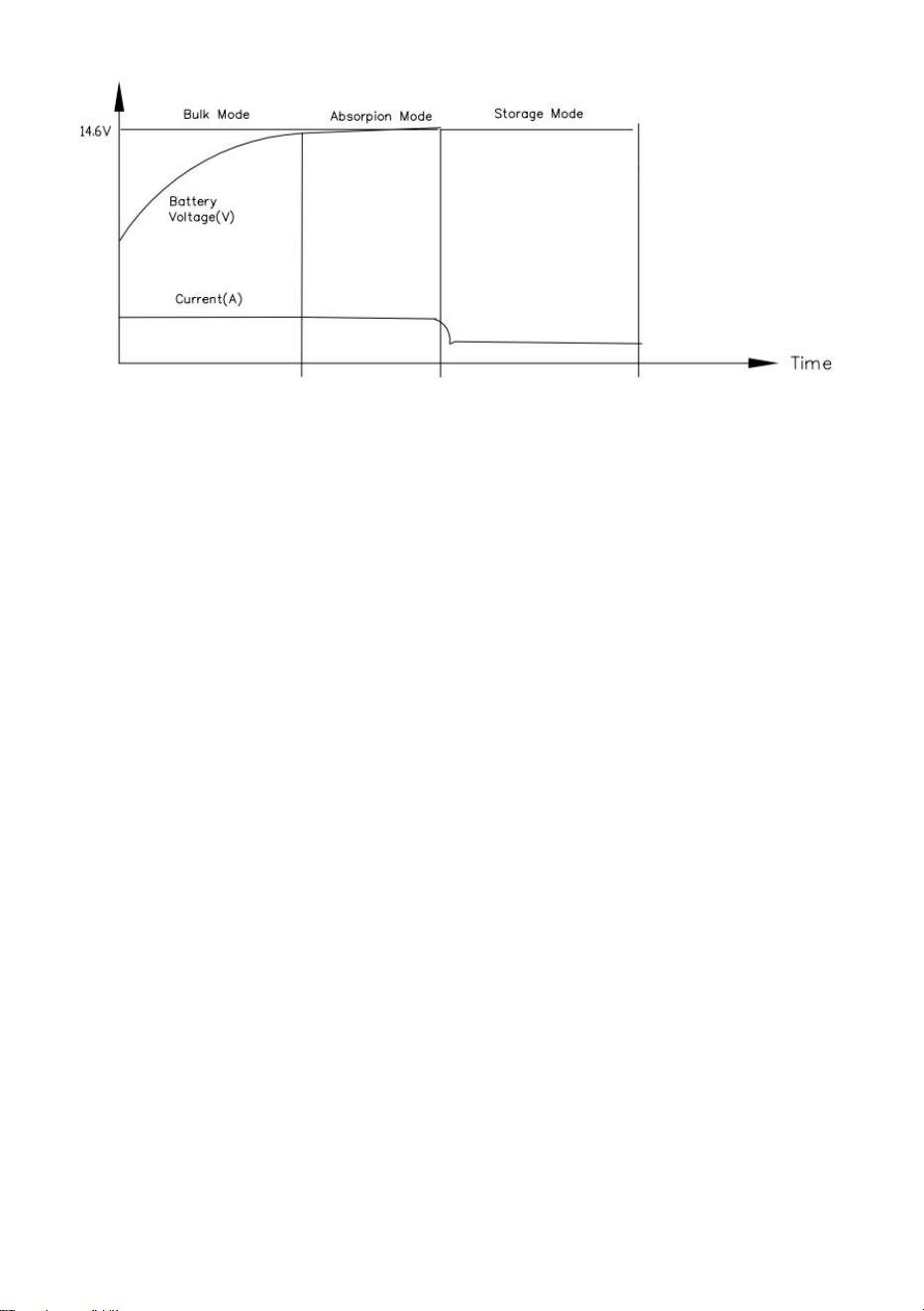
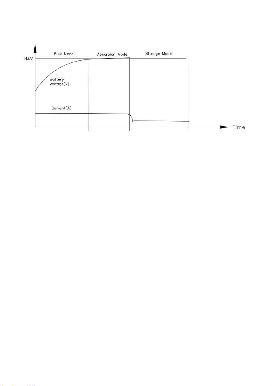
10.Lithium battery 3 STAGE CHARGING MODE:
LED2 is lit blue.This mode provides an automatic charging system in
three steps.(Figure 2)
(1)A fast charge to bring a good, drained battery back up to full voltage
rapidly.LED2 blue LED4 red.
(2)A standard charge to bring the battery up to a full charge at a safe rate to
prolong the life of the battery and provide power to run 12V lighting and
appliances in the vehicle/device ("Absorption").LED2 blue LED4 red.The
charging voltage is set to 14.6V.
(3)When the Absorption charging current is less than 15% of the maximum
output current , the charger will enter Storage mode. .LED2 blue . The
charging voltage is set to 14.6V. If the charging current exceeds 50% of
the maximum output current for more than 30 seconds, the charger will
re-enter the Bulk and start a new charging cycle.
- 6 -
Figure 2
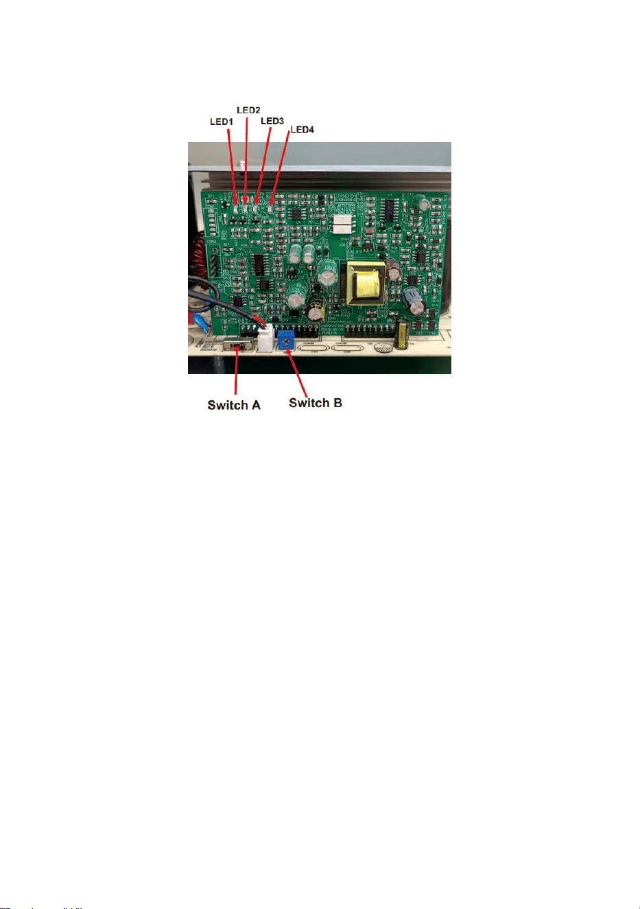
11.FIXED VOLTAGE Mode.
(1)This mode can be used to directly power 12 Volt equipment and or
maintain the battery at that voltage.
(2)To set to fixed mode, with the unit turned off, move switch A right to the
"Fixed Voltage" position and plug the unit into a 120V power supply,
LED2 blue on LED3 orange on. Gently turn the output voltage
adjustment potentiometer counterclockwise or clockwise to adjust the
voltage within the range of 13-16.5V.
Note: Now, every time the unit is powered on, the output voltage you set
will be fixed at the already adjusted voltage value.
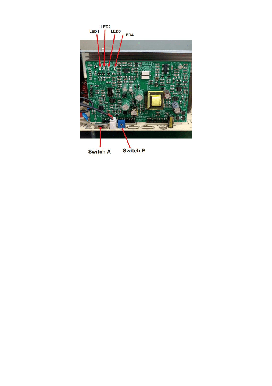
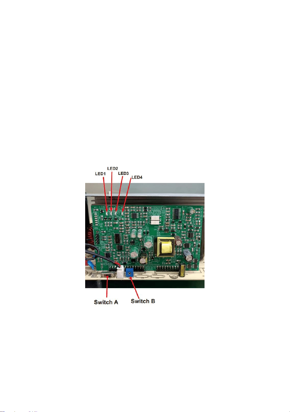
12.Switch A and Switch B: Switch A is a three-segment selector switch that
selects Acid Mode/Fixed Output Mode/Lithium Mode from left to right.
Switch B is an adjustable potentiometer that adjusts the 13.0V-16.5V
output voltage range from clockwise in the fixed output mode state
(switch B is not adjustable in acid mode/lithium mode).(Figure 3).
- 7 -
Figure 3
13.LED Indicators: LED1 Green light indicates acid battery mode. LED2
Blue light indicates lithium battery mode. LED3 LED3 Orange light
indicates solid state battery mode or country output mode. LED2 Blue
light indicates lithium battery mode.LED3 Orange light indicates solid
state battery mode or fixed voltage output mode.LED4 Red light
indicates charging, off indicates end of charging or standby.(Figure 3).
NOTE: Before removing and replacing the Converter/charger, perform
the following checks:
Disconnect the AC power from the vehicle/device.
Disconnect the wiring from the positive + output connection line of the
converter.
Re-connect the AC power to energize the Converter.
Using a voltmeter, measure the voltage at the Converter - and + Output
Terminals:
If the voltage reading is between 13VDC and 14VDC (usually 13.6 VDC),
the unit is normal. Otherwise, follow the general fault cause and
troubleshooting table.
- 8 -
PARAMETER SPECIFICATIONS
sports event
parameters
Input Power
AC 120V 60Hz
Maximum Output Current
55A
output voltage
fixed mode:13-16.5V
lead-acid battery:12-14.6V
Lithium battery:12-14.6V
GENERAL PROBLEM TROUBLESHOOTING
fault phenomenon
General solutions
No DC output
120 VAC not connected to coach or the coach AC
circuit breaker is in the off position.
The reversed battery fuse blows. (Battery polarity
reversed)
If the load is seriously overloaded or short-circuited,
remove all loads and then restart the power supply.
Converter cycles On & Off
Fan air flow is inadequate or blocked. (1” minimum free
air space at each end required).
The DC fuse blows
The battery is reversed polarity
12 VDC output is too low
Defective battery, possible bad cells
LED light is not on
The battery is fully charged
The battery voltage is high and the charger maximum
output voltage
Note:If the converter still does not work properly after checking according
to the above methods, please contact the dealer to solve the problem, and
do not disassemble the converter for repair without authorization.

- 9 -
LIST OF ACCESSORIES
1. instruction manual *1
2. Screwdriver *1
Manufacturer: Shanghaimuxinmuyeyouxiangongsi
Address: Shuangchenglu 803nong11hao1602A-1609shi, baoshanqu,
shanghai 200000 CN.
Imported to AUS: SIHAO PTY LTD, 1 ROKEVA STREETEASTWOOD NSW
2122 Australia
Imported to USA: Sanven Technology Ltd., Suite 250, 9166 Anaheim Place,
Rancho Cucamonga, CA 91730
REP
EC
E-CrossStu GmbH
Mainzer Landstr.69, 60329 Frankfurt am Main.
REP
UK
YH CONSULTING LIMITED.
C/O YH Consulting Limited Office 147, Centurion House,
London Road, Staines-upon-Thames, Surrey, TW18 4AX


Technique Assistance et certificat de garantie électronique
www.vevor.com/support
Redresseur/chargeur AC-DC pour camping-car
Manuel d'instructions
Modèle : GS800RVP-55
We continue to be committed to provide you tools with competitive price.
"Save Half", "Half Price" or any other similar expressions used by us only represents an
estimate of savings you might benefit from buying certain tools with us compared to the major
top brands and does not necessarily mean to cover all categories of tools offered by us. You
are kindly reminded to verify carefully when you are placing an order with us if you are
actually saving half in comparison with the top major brands.

- 1 -
MODÈLE : GS800RVP-55
Have product questions? Need technical support? Please feel free to
contact us:
Technical Support and E-Warranty Certificate
www.vevor.com/support
NEED HELP? CONTACT US!
This is the original instruction, please read all manual instructions
carefully before operating. VEVOR reserves a clear interpretation of our
user manual. The appearance of the product shall be subject to the
product you received. Please forgive us that we won't inform you again if
there are any technology or software updates on our product.
AC-DC Rectifier /
Charger for RV

- 2 -
Avertissement : Pour réduire le risque de blessure, l'utilisateur doit
lire attentivement le manuel d'instructions.
Cet appareil est conforme à la partie 15 des règles FCC. Son
fonctionnement est soumis aux deux conditions suivantes : (1) Cet
appareil ne doit pas provoquer d'interférences nuisibles et (2) cet
appareil doit accepter toute interférence reçue, y compris les
interférences susceptibles de provoquer un fonctionnement
indésirable.
Ce produit est soumis aux dispositions de la directive européenne
2012/19/CE. Le symbole représentant une poubelle barrée indique
que le produit nécessite une collecte sélective des déchets dans
l'Union européenne. Ceci s'applique au produit et à tous les
accessoires marqués de ce symbole. Les produits marqués comme
tels ne peuvent pas être jetés avec les ordures ménagères normales,
mais doivent être déposés dans un point de collecte pour le
recyclage des appareils électriques et électroniques.
SAFETY WARNINGS
POUR VOTRE SÉCURITÉ, LISEZ TOUTES LES INSTRUCTIONS AVANT
INSTALLATION ET FONCTIONNEMENT .
INSTALLATEUR : FOURNISSEZ CES INSTRUCTIONS À L'UTILISATEUR
FINAL OU
Consommer .
CONSOMMATEUR : CONSERVEZ CES INSTRUCTIONS POUR RÉFÉRENCE
FUTURE.
AVIS : LES PRODUITS NE DOIVENT PAS ÊTRE UTILISÉS ET NE SONT PAS
GARANTIS DANS
APPLICATIONS AÉROSPATIALES, MÉDICALES OU DE SÉCURITÉ DES
PERSONNES.
AVERTISSEMENT
–
ÉVITEZ LES BLESSURES CORPORELLES OU

- 3 -
LES DOMMAGES AU PRODUIT.
120 VAC EST PRÉSENT. CE CONVERTISSEUR/CHARGEUR EST CONÇU
POUR
CONVERTIR 120 VCA EN 12 VCC. IL FOURNIT ÉGALEMENT UNE
ALIMENTATION BASSE TENSION POUR CHARGER LES BATTERIES 12 V
CC INTÉGRÉES. LE CONVERTISSEUR/CHARGEUR EST DE TYPE «
SWITCH MODE » ET EST CONÇU
NE NÉCESSITER AUCUN ENTRETIEN ET NE PEUT ÊTRE RÉPARÉ PAR
L'UTILISATEUR
COMPOSANTS. LA PUISSANCE DE SORTIE DU
CONVERTISSEUR/CHARGEUR I
« LIMITATION DE COURANT » PAR CONCEPTION.
NE JAMAIS RANGER LES APPAREILS ÉLECTRIQUES DANS DES
COMPARTIMENTS OÙ
IL EXISTE DES LIQUIDES INFLAMMABLES (COMME L
’
ESSENCE). NE PAS
MONTER/INSTALLER L'UNITÉ DANS DES COMPARTIMENTS CONÇUS
POUR LE STOCKAGE DE BATTERIES DE LIQUIDES INFLAMMABLES.
INSTALLATION INSTRUCTIONS
Le convertisseur/chargeur AC-DC dispose de trois modes : charge de
batterie acide et de batterie au lithium et sortie fixe.
14.Débranchez le fil POS (+) de la batterie à l'extrémité de la batterie avant
de connecter ce convertisseur/chargeur à tout câblage de
véhicule/appareil.
15.L'emplacement d'installation peut être situé sur n'importe quelle surface
interne (non affectée par les intempéries directes). L'emplacement choisi
doit être accessible après les heures suivantes d'installation. Lorsqu’elle
est installée à l’intérieur d’une armoire, celle-ci doit être suffisamment

- 4 -
grande pour dissiper l’ air chaud. Assurez-vous qu'il y a au moins 1
pouce (1 pouce) d'espace d'air libre à chaque extrémité de l'unité afin
que l'air de refroidissement puisse passer normalement à travers
l'appareil. Évitez les contaminants tels que la saleté périphérique, les
particules métalliques ou l'humidité.
16.Des brides avec des trous sont fournies pour faciliter le montage à
l'aide de fixations standard. Confirmez que la surface sur laquelle le
convertisseur est monté est solide et supportera le poids (6 lb) pendant
le fonctionnement du véhicule .
17.La prise de 120 VCA doit être située à moins de 36 pouces du
convertisseur/chargeur pour fournir de l'alimentation. Une attention
électrique doit également être accordée au montage à proximité des
emplacements des batteries et du panneau de distribution 12 volts CC.
18.Assurez-vous de bien serrer toutes les connexions. Une connexion
desserrée peut rapidement provoquer une surchauffe des bornes et des
fils. Consultez les étiquettes de l’unité pour connaître les valeurs de
couple aux bornes recommandées.
19.Le ventilateur ne fonctionnera pas tout le temps. Le ventilateur est à
température contrôlée et ne fonctionne qu'en cas de besoin.
20.Une fois branché, ne laissez jamais l'appareil sans surveillance.
21.Tous les produits doivent être installés par un électricien certifié .
AVERTISSEMENT : évitez les blessures possibles, voire la mort .
Connexion 120 VAC : Vérifiez d'abord que la source d'alimentation 120
VAC AC
le(s) disjoncteur(s) sont en position d'arrêt. NE PAS activer les
disjoncteurs CA tant que l'installation n'est pas terminée .
Utiliser un 8 Fil de cuivre de taille minimale AWG, fixez-le à partir du
châssis du véhicule/appareil à la cosse de liaison du
convertisseur/chargeur. À l'aide du cordon d'alimentation fourni sur le
convertisseur/chargeur, connectez-le fermement au réseau 120 V. Prise

- 5 -
secteur .
12 VCC Câblage – Il est important d’utiliser le bon calibre de fil. Utiliser
un
minimum de fil de cuivre de taille 8 AWG.
(4)La borne marquée + ou POS est destinée à la connexion positive RV
12VDC .
(5)Le terminal marqué - ou NEG est pour la connexion négative RV12VDC.
(6)Le câblage de sortie 12 V CC ne nécessite pas de protection contre les
surintensités.
car le convertisseur/chargeur limite la sortie de courant. Cependant,
toutes les connexions électriques doivent être conformes au code NEC
approprié .
22.Mode batterie au plomb :
Entrez dans ce mode, la LED1 s'allume en vert. Ce mode fournit un
système de charge automatique à travers quatre modes. (Figure 1).
(5)Charge rapide à courant constant (mode Bulk), de sorte que la
puissance soit
épuisé et rétablit rapidement la pleine tension, LED1 est vert vif, LED4
est rouge vif.
(6)Lorsque la tension de la batterie atteint environ 14,6 V, elle entre dans la
valeur constante
mode de charge de tension (mode absorption) à un rythme sûr pour
prolonger la durée de vie de la batterie et de l'alimentation. LED1 Vert
LED4 Rouge.
(7)Lorsque le courant de charge est inférieur à 15 % de la puissance
maximale
courant ou lorsque le chargeur a été chargé pendant 4 heures, selon la
première éventualité, le chargeur entrera en mode Bulk. La LED1 est
verte. La tension de charge est d'environ 13,6 V. Si le courant de charge
dépasse 50 % du courant de sortie maximum pendant plus de 30
secondes, le chargeur entrera à nouveau en mode Bulk et commencera
un nouveau cycle de charge. Si le chargeur reste en mode Absorption
- 6 -
pendant 48 heures, il passera en mode Stockage.
Traduit avec (version gratuite) .
(8)Chargement d'entretien, qui est utilisé pour maintenir la batterie au frais
(« stockage »)
pendant les périodes d'inactivité de la charge. Le chargeur change
automatiquement de mode pour s'adapter aux changements de
conditions. La LED1 est verte et la tension de charge est d'environ 13,2
V et la tension peut varier en fonction de la batterie. Si le courant de
charge dépasse 50 % du courant de sortie maximum pendant plus de 30
secondes, le chargeur entrera à nouveau en charge à courant constant
et démarrera un nouveau cycle de charge.
Figure 1
23.Batterie au lithium MODE DE CHARGE EN 3 ÉTAPES :
La LED2 est allumée en bleu. Ce mode fournit un système de charge
automatique en trois étapes . (Figure 2)
(4)Une charge rapide pour ramener une batterie en bon état et épuisée à
sa pleine tension
rapidement.LED2 bleu LED4 rouge.
(5)Une charge standard pour amener la batterie à une charge complète à
un rythme sûr pour
prolonger la durée de vie de la batterie et fournir de l'énergie pour faire
fonctionner l'éclairage et les appareils 12 V dans le véhicule/appareil («
- 7 -
Absorption »). LED2 bleues LED4 rouges. La tension de charge est
réglée sur 14,6 V.
(6)Lorsque le courant de charge d'absorption est inférieur à 15 % du
maximum
courant de sortie, le chargeur entrera en mode stockage. .LED2 bleue .
La tension de charge est réglée à 14,6 V. Si le courant de charge
dépasse 50 % du courant de sortie maximum pendant plus de 30
secondes, le chargeur entrera à nouveau dans le Bulk et démarrera un
nouveau cycle de charge .
Figure 2
24.Mode TENSION FIXE .
(3)Ce mode peut être utilisé pour alimenter directement un équipement 12
Volts et/ou maintenir la batterie à cette tension .
(4)Pour passer en mode fixe, l'appareil étant éteint, déplacez l'interrupteur
A vers la droite.
Position « Tension fixe » et branchez l'appareil sur une alimentation 120
V, LED2 bleue allumée LED3 orange allumée. Tournez doucement le
potentiomètre de réglage de la tension de sortie dans le sens inverse
des aiguilles d'une montre ou dans le sens des aiguilles d'une montre
pour régler la tension dans la plage de 13 à 16,5 V.
Remarque : Désormais, chaque fois que l'appareil est allumé, la tension
de sortie que vous définissez sera fixée à la valeur de tension déjà
- 8 -
ajustée.
25.Commutateur A et commutateur B : le commutateur A est un sélecteur à
trois segments qui
sélectionne le mode acide/le mode de sortie fixe/le mode lithium de
gauche à droite. Le commutateur B est un potentiomètre réglable qui
ajuste la plage de tension de sortie 13,0 V-16,5 V dans le sens des
aiguilles d'une montre en mode de sortie fixe (le commutateur B n'est
pas réglable en mode acide/mode lithium). (Figure 3).
figure 3
26.Indicateurs LED : Le voyant vert LED1 indique le mode batterie acide.
LED2
La lumière bleue indique le mode batterie au lithium. LED3 LED3 Le
voyant orange indique le mode batterie solide ou le mode de sortie pays.
La lumière bleue LED2 indique le mode batterie au lithium. La lumière

- 9 -
orange LED3 indique le mode batterie à semi-conducteurs ou le mode
de sortie à tension fixe. La lumière rouge LED4 indique la charge,
l'extinction indique la fin de la charge ou la veille. (Figure 3).
REMARQUE : Avant de retirer et de remplacer le
convertisseur/chargeur, effectuez les vérifications suivantes :
Débranchez l'alimentation secteur du véhicule/appareil .
Débranchez le câblage de la ligne de connexion positive + sortie du
convertisseur.
Rebranchez l'alimentation secteur pour mettre le convertisseur sous
tension .
À l'aide d'un voltmètre, mesurez la tension aux sorties Convertisseur - et
+
Bornes :
Si la tension mesurée est comprise entre 13 VCC et 14 VCC
(généralement 13,6 VCC) ,
l'unité est normale. Sinon, suivez la cause générale du défaut et le
tableau de dépannage .
PARAMETER SPECIFICATIONS
événement sportif
paramètres
La puissance d'entrée
C.A. 120 V 60 Hz
Courant de sortie maximal
55A
tension de sortie
mode fixe : 13-16,5 V
Batterie au plomb : 12-14,6 V
Lithium batterie : 12-14,6 V
GENERAL PROBLEM TROUBLESHOOTING
phénomène de défaut
Solutions générales
Le 120 VCA n'est pas connecté à l'autocar ou le

- 10 -
Pas de sortie CC
disjoncteur CA de l'autocar est en position d'arrêt .
Le fusible de la batterie inversé grille. (Polarité de la
batterie inversée)
Si la charge est sérieusement surchargée ou en
court-circuit, retirez toutes les charges, puis
redémarrez l'alimentation électrique.
Cycles du convertisseur
marche et arrêt
Le débit d’air du ventilateur est insuffisant ou bloqué.
(Espace d'air libre minimum de 1" à chaque extrémité
requis) .
Le fusible CC saute
La batterie est à polarité inversée
La sortie 12 V CC est trop
faible
Batterie défectueuse, cellules défectueuses possibles
La lumière LED n'est pas
allumée
La batterie est complètement chargée
La tension de la batterie est élevée et la tension de
sortie maximale du chargeur
N ote : Si le convertisseur ne fonctionne toujours pas correctement après
avoir vérifié selon les méthodes ci-dessus, veuillez contacter le revendeur
pour résoudre le problème et ne démontez pas le convertisseur pour le
réparer sans autorisation.
LIST OF ACCESSORIES
3. manuel d'instructions *1
4. Tournevis * 1
Fabricant : Shanghaimuxinmuyeyouxiangongsi
Adresse : Shuangchenglu 803nong11hao1602A-1609shi, baoshanqu,
shanghai 200000 CN.
Importé en Australie : SIHAO PTY LTD, 1 ROKEVA STREETASTWOOD

- 11 -
NSW 2122 Australie
Importé aux États-Unis : Sanven Technology Ltd., Suite 250, 9166 Anaheim
Place, Rancho Cucamonga, CA 91730
REP
EC
E-CrossStu GmbH
Mainzer Landstr.69, 60329 Frankfurt am Main.
REP
UK
YH CONSULTING LIMITED.
C/O YH Consulting Limited Office 147, Centurion House,
London Road, Staines-upon-Thames, Surrey, TW18 4AX


Technisch Support und E-Garantie-Zertifikat
www.vevor.com/support
AC-DC-Gleichrichter/Ladegerät für Wohnmobile
Bedienungsanleitung
Modell: GS800RVP-55
We continue to be committed to provide you tools with competitive price.
"Save Half", "Half Price" or any other similar expressions used by us only represents an
estimate of savings you might benefit from buying certain tools with us compared to the major
top brands and does not necessarily mean to cover all categories of tools offered by us. You
are kindly reminded to verify carefully when you are placing an order with us if you are
actually saving half in comparison with the top major brands.
- 1 -
MODELL: GS800RVP-55
Have product questions? Need technical support? Please feel free to
contact us:
Technical Support and E-Warranty Certificate
www.vevor.com/support
NEED HELP? CONTACT US!
This is the original instruction, please read all manual instructions
carefully before operating. VEVOR reserves a clear interpretation of our
user manual. The appearance of the product shall be subject to the
product you received. Please forgive us that we won't inform you again if
there are any technology or software updates on our product.
AC-DC Rectifier /
Charger for RV

- 2 -
Warnung: Um das Verletzungsrisiko zu verringern, muss der
Benutzer die Bedienungsanleitung sorgfältig lesen.
Dieses Gerät entspricht Teil 15 der FCC-Bestimmungen. Der Betrieb
unterliegt den folgenden beiden Bedingungen: (1) Dieses Gerät darf
keine schädlichen Störungen verursachen und (2) dieses Gerät
muss alle empfangenen Störungen akzeptieren, einschließlich
Störungen, die einen unerwünschten Betrieb verursachen können.
Dieses Produkt unterliegt den Bestimmungen der europäischen
Richtlinie 2012/19/EU. Das Symbol einer durchgestrichenen
Mülltonne weist darauf hin, dass das Produkt in der Europäischen
Union einer getrennten Müllentsorgung unterliegt. Dies gilt für das
Produkt und alle mit diesem Symbol gekennzeichneten Zubehörteile.
So gekennzeichnete Produkte dürfen nicht im normalen Hausmüll
entsorgt werden, sondern müssen an einer Sammelstelle für das
Recycling von elektrischen und elektronischen Geräten abgegeben
werden.
SAFETY WARNINGS
LESEN SIE ZU IHRER SICHERHEIT ALLE ANWEISUNGEN VORHER
INSTALLATION UND BETRIEB .
INSTALLATEUR : GEBEN SIE DIESE ANLEITUNG AN DEN ENDBENUTZER
WEITER ODER
Konsumieren .
VERBRAUCHER : BEWAHREN SIE DIESE ANLEITUNG ZUM SPÄTEREN
NACHSCHLAGEN AUF.
HINWEIS : DIE PRODUKTE SIND NICHT FÜR DEN GEBRAUCH BESTIMMT
UND UNTERLIEGEN AUCH NICHT DER GARANTIE IN
ANWENDUNGEN IN DER LUFT- UND RAUMFAHRT, MEDIZIN ODER
LEBENSSICHERHEIT.
WARNUNG
–
VERMEIDEN SIE VERLETZUNGEN ODER

- 3 -
PRODUKTSCHÄDEN.
120 VAC IST VORHANDEN. DIESER KONVERTER/LADEGERÄT IST DAFÜR
AUSGELEGT,
WANDELT 120 VAC IN 12 VDC UM. ES BIETET AUCH
NIEDERSPANNUNGSSTROM ZUM LADEN VON 12 VDC-BORDBATTERIEN.
DER KONVERTER/LADEGERÄT IST EIN „ SCHALTMODUS “ -TYP UND IST
KONZIPIERT
WARTUNGSFREI UND OHNE BENUTZERWARTUNG
KOMPONENTEN. DER KONVERTER/LADEGERÄT-LEISTUNGSAUSGANG I
„ STROMBEGRENZEND “ DURCH DESIGN.
BEWAHREN SIE ELEKTRISCHE GERÄTE NIEMALS IN FÄCHERN AUF, IN
DENEN
ES SIND BRENNBARE FLÜSSIGKEITEN (WIE BENZIN) VORHANDEN.
MONTIEREN/INSTALLIEREN SIE DAS GERÄT NICHT IN FÄCHERN, DIE
FÜR DIE LAGERUNG VON BATTERIEN ODER BRENNBAREN
FLÜSSIGKEITEN VORGESEHEN SIND.
INSTALLATION INSTRUCTIONS
Der AC-DC-Konverter/das Ladegerät verfügt über drei Modi: Laden von
Säurebatterien und Lithiumbatterien sowie feste Ausgabe.
27.Trennen Sie das Batterie-Pluskabel (+) am Batterieende, bevor Sie
diesen Konverter/Ladegerät an eine Fahrzeug-/Geräteverkabelung
anschließen.
28.Der Installationsort kann auf jeder beliebigen Innenfläche (ohne direkte
Witterungseinflüsse) liegen. Der ausgewählte Ort muss nach den
folgenden Installationsstunden zugänglich sein. Bei der Installation in
einem Schrank muss der Schrank groß genug sein, um heiße Luft
abzuleiten. Stellen Sie sicher, dass an jedem Ende des Geräts
mindestens 1 Zoll (2,5 cm) freier Luftraum vorhanden ist, damit Kühlluft
normal durch das Gerät strömen kann. Vermeiden Sie Verunreinigungen
wie Schmutz, Metallpartikel oder Feuchtigkeit.
29.Zur einfachen Montage mit Standardbefestigungen sind Flansche mit

- 4 -
Löchern im Lieferumfang enthalten. Stellen Sie sicher, dass die
Oberfläche, an der der Konverter montiert wird, stabil ist und das
Gewicht (6 lbs) während des Fahrzeugbetriebs aushält .
30.Die 120-V-Wechselstromsteckdose muss sich in einem Umkreis von 36
Zoll um den Konverter/Ladegerät befinden, um Strom zu liefern.
Elektrische Überlegungen sollten auch angestellt werden, wenn die
Montage in der Nähe der Batterien und des
12-Volt-Gleichstromverteilers erfolgen soll.
31.Achten Sie darauf, alle Verbindungen fest anzuziehen. Eine lose
Verbindung kann schnell zu einer Überhitzung von Klemmen und Kabeln
führen. Die empfohlenen Drehmomentwerte für die Klemmen finden Sie
auf den Geräteetiketten.
32.Der Lüfter läuft nicht die ganze Zeit. Der Lüfter ist temperaturgesteuert
und läuft nur bei Bedarf.
33.Lassen Sie das Gerät nach dem Einstecken nie unbeaufsichtigt.
34.Alle Produkte müssen von einem zertifizierten Elektriker installiert
werden .
WARNUNG : Vermeiden Sie mögliche Verletzungen oder
Todesfälle .
120 VAC-Anschluss : Stellen Sie zunächst sicher, dass die 120
VAC-Stromquelle AC
Die Schutzschalter sind ausgeschaltet. Schalten Sie die
AC-Schutzschalter NICHT ein, bevor die Installation abgeschlossen ist .
Mit einem 8 AWG Mindestgröße Kupferdraht, befestigen Sie von der
Fahrzeug-/Gerätechassis mit der Erdungsklemme des
Konverters/Ladegeräts verbinden. Verbinden Sie das
Konverter-/Ladegerät mit dem beiliegenden Netzkabel fest mit dem
120-V- AC-Steckdose .
12 V Gleichstrom Verdrahtung - Es ist wichtig, den richtigen
Drahtquerschnitt zu verwenden. Verwenden Sie
mindestens Kupferdraht der Größe 8 AWG.
(7)Die mit + oder POS gekennzeichnete Klemme ist für den positiven

- 5 -
12-VDC-Anschluss des RV .
(8)- oder - gekennzeichnete Klemme NEG ist für den negativen Anschluss
des RV12VDC.
(9)Die 12VDC-Ausgangsverkabelung erfordert keinen Überstromschutz
da der Konverter/das Ladegerät die Stromabgabe begrenzt. Alle
elektrischen Anschlüsse müssen jedoch dem entsprechenden
NEC-Code entsprechen .
35.Blei-Säure-Batteriemodus :
Wechseln Sie in diesen Modus, LED1 leuchtet grün. Dieser Modus bietet
ein automatisches Ladesystem mit vier Modi (Abbildung 1).
(9)Konstantstrom-Schnellladung (Bulk Mode), so dass die Leistung
erschöpft und stellt schnell die volle Spannung wieder her, LED1
leuchtet hellgrün, LED4 leuchtet hellrot.
(10)Wenn die Batteriespannung etwa 14,6 V erreicht, tritt sie in den
konstanten
Spannungslademodus (Absorptionsmodus) mit einer sicheren Rate, um
die Lebensdauer der Batterie und des Netzteils zu verlängern. LED1
Grün LED4 Rot.
(11)Wenn der Ladestrom weniger als 15 % der maximalen Leistung beträgt
Strom oder wenn das Ladegerät 4 Stunden lang geladen wurde, je
nachdem, was zuerst eintritt, wechselt das Ladegerät in den Bulk-Modus.
LED1 ist grün. Die Ladespannung beträgt ca. 13,6 V. Wenn der
Ladestrom länger als 30 Sekunden 50 % des maximalen
Ausgangsstroms überschreitet, wechselt das Ladegerät erneut in den
Bulk-Modus und beginnt einen neuen Ladezyklus. Wenn das Ladegerät
48 Stunden lang im Absorb-Modus bleibt, wechselt es in den
Storage-Modus.
Übersetzt mit (kostenlose Version) .
(12)Erhaltungsladung, die dazu dient, die Batterie frisch zu halten ( „
Lagerung“)
während Zeiten der Inaktivität der Ladung. Das Ladegerät ändert
- 6 -
automatisch den Modus, um sich an veränderte Bedingungen
anzupassen. LED1 ist grün und die Ladespannung beträgt etwa 13,2 V.
Die Spannung kann je nach Batterie variieren. Wenn der Ladestrom
länger als 30 Sekunden 50 % des maximalen Ausgangsstroms
überschreitet, wechselt das Ladegerät wieder in den
Konstantstrom-Lademodus und startet einen neuen Ladezyklus.
Abbildung 1
36.Lithiumbatterie 3-STUFEN-LADEMODUS :
LED2 leuchtet blau. Dieser Modus bietet ein automatisches
Ladesystem in drei Schritten . (Abbildung 2)
(7)Eine schnelle Aufladung, um eine gute, entladene Batterie wieder auf
volle Spannung zu bringen
schnell.LED2 blau LED4 rot.
(8)Eine Standardladung, um die Batterie mit einer sicheren
Geschwindigkeit vollständig aufzuladen, um
verlängern die Lebensdauer der Batterie und liefern Strom für den
Betrieb von 12V-Beleuchtung und Geräten im Fahrzeug/Gerät
(„Absorption“). LED2 blau LED4 rot. Die Ladespannung ist auf 14,6V
eingestellt .
(9)Wenn der Absorptionsladestrom weniger als 15 % des Maximums
beträgt
Ausgangsstrom, das Ladegerät wechselt in den Lagermodus. .LED2
- 7 -
blau. Die Ladespannung ist auf 14,6 V eingestellt. Wenn der Ladestrom
länger als 30 Sekunden 50 % des maximalen Ausgangsstroms
überschreitet, wechselt das Ladegerät wieder in den Bulk-Modus und
startet einen neuen Ladezyklus .
Figur 2
37.FESTSPANNUNG-Modus .
(5)Dieser Modus kann verwendet werden, um 12-Volt-Geräte direkt mit
Strom zu versorgen und/oder die Batteriespannung auf dieser
Spannung zu halten .
(6)Um den Festmodus bei ausgeschaltetem Gerät einzustellen, schieben
Sie den Schalter A nach rechts in die
Position „ Feste Spannung “ und stecken Sie das Gerät in eine
120-V-Stromversorgung, LED2 blau an, LED3 orange an. Drehen Sie
das Potentiometer zur Einstellung der Ausgangsspannung vorsichtig
gegen den Uhrzeigersinn oder im Uhrzeigersinn, um die Spannung im
Bereich von 13–16,5 V einzustellen.
Hinweis: Bei jedem Einschalten des Geräts wird die von Ihnen
eingestellte Ausgangsspannung nun auf den bereits angepassten
Spannungswert festgelegt.

- 8 -
38.Schalter A und Schalter B: Schalter A ist ein dreiteiliger Wahlschalter,
der
wählt von links nach rechts den
Säuremodus/Festausgabemodus/Lithiummodus. Schalter B ist ein
einstellbares Potentiometer, das den Ausgangsspannungsbereich von
13,0 V bis 16,5 V im Uhrzeigersinn im Zustand des Festausgabemodus
einstellt (Schalter B ist im Säuremodus/Lithiummodus nicht einstellbar).
(Abbildung 3).
Figur 3
39.LED-Anzeigen: LED1 Grünes Licht zeigt den Säurebatteriemodus an.
LED2
Blaues Licht zeigt den Lithiumbatteriemodus an. LED3 LED3
Orangefarbenes Licht zeigt den Festkörperbatteriemodus oder den
Festspannungsausgabemodus an. LED2 Blaues Licht zeigt den
Lithiumbatteriemodus an.LED3 Orangefarbenes Licht zeigt den

- 9 -
Festkörperbatteriemodus oder den Festspannungsausgabemodus
an.LED4 Rotes Licht zeigt den Ladevorgang an, Aus zeigt das Ende des
Ladevorgangs oder den Standby-Modus an. (Abbildung 3).
HINWEIS: Führen Sie vor dem Entfernen und Ersetzen des
Konverters/Ladegeräts die folgenden Prüfungen durch:
Trennen Sie das Fahrzeug/Gerät von der Stromversorgung .
Trennen Sie die Verkabelung von der positiven +
Ausgangsanschlussleitung des
Konverter.
Schließen Sie die Wechselstromversorgung erneut an, um den Konverter
mit Strom zu versorgen .
Messen Sie mit einem Voltmeter die Spannung am Konverter - und +
Ausgang
Anschlüsse :
Wenn die Spannung zwischen 13 VDC und 14 VDC (normalerweise 13,6
VDC) liegt ,
das Gerät ist normal. Andernfalls folgen Sie der allgemeinen
Fehlerursachen- und Fehlerbehebungstabelle .
PARAMETER SPECIFICATIONS
Sportveranstaltung
Parameter
Eingangsleistung
Wechselstrom 120 V, 60 Hz
Maximaler Ausgangsstrom
55A
Ausgangsspannung
Fester Modus: 13–16,5 V
Blei-Säure-Batterie : 12–14,6 V
Lithium Batterie : 12-14,6 V
GENERAL PROBLEM TROUBLESHOOTING

- 10 -
Fehlerphänomen
Allgemeine Lösungen
Kein DC-Ausgang
120 VAC nicht an den Bus angeschlossen oder der
AC-Leistungsschalter des Busses ist in der
Aus-Position .
Die vertauschte Batteriesicherung brennt durch.
(Batteriepolarität vertauscht)
Bei starker Überlastung oder Kurzschluss der Last
entfernen Sie sämtliche Lasten und starten Sie die
Stromversorgung neu.
Konverterzyklen Ein und
Aus
Der Luftstrom des Ventilators ist unzureichend oder
blockiert. (An jedem Ende ist mindestens ein freier
Luftraum von 1 Zoll erforderlich) .
Die DC-Sicherung brennt
durch
Die Batterie hat eine umgekehrte Polarität
12 VDC-Ausgang ist zu
niedrig
Defekte Batterie, möglicherweise defekte Zellen
LED-Licht leuchtet nicht
Der Akku ist vollständig geladen
Die Batteriespannung ist hoch und die maximale
Ausgangsspannung des Ladegeräts
Hinweis : Wenn der Konverter nach der Überprüfung gemäß den oben
genannten Methoden immer noch nicht ordnungsgemäß funktioniert,
wenden Sie sich bitte an den Händler, um das Problem zu lösen, und
zerlegen Sie den Konverter nicht eigenmächtig zur Reparatur .
LIST OF ACCESSORIES
5. Bedienungsanleitung *1
6. Schraubendreher *1

- 11 -
Hersteller: Shanghaimuxinmuyeyouxiangongsi
Adresse: Shuangchenglu 803nong11hao1602A-1609shi, Baoshanqu,
Shanghai 200000 CN.
Nach AUS importiert: SIHAO PTY LTD, 1 ROKEVA STREETEASTWOOD
NSW 2122 Australien
Importiert in die USA: Sanven Technology Ltd., Suite 250, 9166 Anaheim
Place, Rancho Cucamonga, CA 91730
REP
EC
E-CrossStu GmbH
Mainzer Landstr.69, 60329 Frankfurt am Main.
REP
UK
YH CONSULTING LIMITED.
C/O YH Consulting Limited Office 147, Centurion House,
London Road, Staines-upon-Thames, Surrey, TW18 4AX


Tecnico Supporto e certificato di garanzia elettronica
www.vevor.com/support
Raddrizzatore/caricabatterie AC-DC per camper
Manuale di istruzioni
Modello: GS800RVP-55
We continue to be committed to provide you tools with competitive price.
"Save Half", "Half Price" or any other similar expressions used by us only represents an
estimate of savings you might benefit from buying certain tools with us compared to the major
top brands and does not necessarily mean to cover all categories of tools offered by us. You
are kindly reminded to verify carefully when you are placing an order with us if you are
actually saving half in comparison with the top major brands.

- 1 -
MODELLO: GS800RVP-55
Have product questions? Need technical support? Please feel free to
contact us:
Technical Support and E-Warranty Certificate
www.vevor.com/support
NEED HELP? CONTACT US!
This is the original instruction, please read all manual instructions
carefully before operating. VEVOR reserves a clear interpretation of our
user manual. The appearance of the product shall be subject to the
product you received. Please forgive us that we won't inform you again if
there are any technology or software updates on our product.
AC-DC Rectifier /
Charger for RV
- 2 -
Avvertenza: per ridurre il rischio di lesioni, l'utente deve leggere
attentamente il manuale di istruzioni.
Questo dispositivo è conforme alla Parte 15 delle norme FCC. Il
funzionamento è soggetto alle seguenti due condizioni: (1) Questo
dispositivo non può causare interferenze dannose e (2) questo
dispositivo deve accettare qualsiasi interferenza ricevuta, comprese
le interferenze che potrebbero causare un funzionamento
indesiderato.
Questo prodotto è soggetto alle disposizioni della Direttiva Europea
2012/19/CE. Il simbolo del bidone della spazzatura barrato indica
che nell'Unione Europea il prodotto richiede la raccolta differenziata
dei rifiuti. Ciò vale per il prodotto e tutti gli accessori contrassegnati
da questo simbolo. I prodotti contrassegnati come tali non possono
essere smaltiti con i normali rifiuti domestici, ma devono essere
portati in un punto di raccolta per il riciclaggio di dispositivi elettrici ed
elettronici
SAFETY WARNINGS
PER LA VOSTRA SICUREZZA, LEGGERE PRIMA TUTTE LE ISTRUZIONI
INSTALLAZIONE E FUNZIONAMENTO .
INSTALLATORE : FORNIRE QUESTE ISTRUZIONI ALL'UTENTE FINALE O
Consumare .
CONSUMATORE :CONSERVARE QUESTE ISTRUZIONI PER RIFERIMENTO
FUTURO.
AVVISO : I PRODOTTI NON DEVONO ESSERE UTILIZZATI NÉ SONO
COPERTI DA GARANZIA
APPLICAZIONI AEROSPAZIALI, MEDICHE O PER LA SICUREZZA DELLA
VITA.
AVVERTENZA
–
EVITARE LESIONI PERSONALI O DANNI AL
PRODOTTO.

- 3 -
SONO PRESENTI 120 VCA. QUESTO CONVERTITORE/CARICATORE È
PROGETTATO PER
CONVERTIRE 120 V CA IN 12 V CC. FORNISCE INOLTRE ALIMENTAZIONE
A BASSA TENSIONE PER CARICARE LE BATTERIE DI BORDO DA 12 VCC.
IL CONVERTITORE/CARICATORE È DEL TIPO “ SWITCH MODE ” ED È
PROGETTATO
ESSERE ESENTE DA MANUTENZIONE E NON RIPARABILE DALL'UTENTE
COMPONENTI. L'USCITA DI POTENZA DEL
CONVERTITORE/CARICABATTERIE I
“ LIMITAZIONE DI CORRENTE ” IN BASE ALLA PROGETTAZIONE.
NON CONSERVARE MAI I DISPOSITIVI ELETTRICI IN SCOMPARTI DOVE
ESISTONO LIQUIDI INFIAMMABILI (COME LA BENZINA). NON
MONTARE/INSTALLARE L'UNITÀ IN SCOMPARTI PROGETTATI PER LO
STOCCAGGIO DI BATTERIE DI LIQUIDI INFIAMMABILI.
INSTALLATION INSTRUCTIONS
Il convertitore/caricabatterie CA-CC dispone di tre modalità: carica della
batteria all'acido e della batteria al litio e uscita fissa.
40.Scollegare il cavo POS (+) della batteria all'estremità della batteria
prima di collegare questo convertitore/caricabatterie a qualsiasi
cablaggio del veicolo/dispositivo
41.La posizione di installazione può essere posizionata su qualsiasi
superficie interna (non influenzata dalle condizioni atmosferiche dirette).
Il luogo selezionato deve essere accessibile dopo gli orari successivi
all'installazione. Se installato all'interno di un armadio, l'armadio deve
essere sufficientemente grande da dissipare l'aria calda. Assicurarsi che
vi sia almeno 1 pollice (1 pollice) di spazio libero su ciascuna estremità
dell'unità in modo che l'aria di raffreddamento possa passare
normalmente attraverso il dispositivo. Evitare contaminanti come sporco
periferico, particelle metalliche o umidità.
42.Sono fornite flange con fori per facilitare il montaggio utilizzando
elementi di fissaggio standard. Verificare che la superficie su cui è

- 4 -
montato il convertitore sia solida e in grado di sostenere il peso (6 libbre)
durante il funzionamento del veicolo .
43.Per fornire alimentazione, la presa da 120 V CA deve essere
posizionata entro 36 pollici dal convertitore/caricatore. Dovrebbe essere
presa in considerazione anche la possibilità di montaggio vicino alle
posizioni delle batterie e del pannello di distribuzione CC da 12 volt.
44.Assicurarsi di serrare saldamente tutte le connessioni. Una
connessione allentata può causare rapidamente il surriscaldamento di
terminali e cavi. Esaminare le etichette dell'unità per i valori di coppia
terminali consigliati.
45.IL fan non funzionerà tutto il tempo. La ventola è a temperatura
controllata e funziona solo quando necessario.
46.Una volta collegato, non lasciare mai il dispositivo incustodito.
47.Tutti i Prodotti devono essere installati da un elettricista certificato .
AVVERTENZA : evitare possibili lesioni o morte .
Collegamento a 120 VCA : verificare innanzitutto che la fonte di
alimentazione a 120 VCA CA
gli interruttori automatici sono in posizione spenta. NON accendere gli
interruttori automatici CA fino al completamento dell'installazione .
Utilizzando un 8 Filo di rame di dimensione minima AWG, collegare da
telaio del veicolo/dispositivo al capocorda di collegamento del
convertitore/caricatore. Utilizzando il cavo di alimentazione in dotazione
al convertitore/caricatore, collegarlo saldamente alla presa da 120 V
Presa CA.
12 VCC Cablaggio : è importante utilizzare il diametro del filo corretto.
Usare un
filo di rame di dimensioni minime 8 AWG.
(10)Il terminale contrassegnato con + o POS è per la connessione positiva
RV 12VDC .
(11)Il terminale contrassegnato - o NEG è per la connessione negativa
RV12VDC.
(12)Il cablaggio di uscita a 12 V CC non richiede protezione da

- 5 -
sovracorrente
perché il convertitore/caricatore limita l'uscita di corrente. Tuttavia, tutti i
collegamenti elettrici devono essere conformi al codice NEC
appropriato .
48.Modalità batteria al piombo :
Entrare in questa modalità, il LED1 si illumina in verde. Questa modalità
fornisce un sistema di ricarica automatico attraverso quattro modalità.
(Figura 1).
(13)Ricarica rapida a corrente costante (modalità Bulk), in modo che la
potenza sia costante
esaurito e ripristina rapidamente la piena tensione, il LED1 è verde
brillante, il LED4 è rosso brillante.
(14)Quando la tensione della batteria raggiunge circa 14,6 V, entra nella
costante
modalità di ricarica della tensione (modalità assorbimento) a una
velocità sicura per prolungare la durata della batteria e dell'alimentatore.
LED1 Verde LED4 Rosso.
(15)Quando la corrente di carica è inferiore al 15% della potenza massima
corrente o quando il caricabatterie è stato caricato per 4 ore, a seconda
di quale evento si verifica per primo, il caricabatterie entrerà in modalità
Bulk. Il LED1 è verde. La tensione di carica è di circa 13,6 V. Se la
corrente di carica supera il 50% della corrente di uscita massima per più
di 30 secondi, il caricabatterie entrerà nuovamente in modalità Bulk e
inizierà un nuovo ciclo di carica. Se il caricabatterie rimane in modalità
Assorbimento per 48 ore, entrerà in modalità Conservazione.
Tradotto con (versione gratuita) .
(16)Carica di mantenimento, utilizzata per mantenere la batteria fresca
("immagazzinamento")
durante i periodi di inattività del carico. Il caricabatterie cambia
automaticamente modalità per adattarsi ai cambiamenti delle condizioni.
Il LED1 è verde e la tensione di carica è di circa 13,2 V e la tensione può
variare a seconda della batteria. Se la corrente di carica supera il 50%
della corrente di uscita massima per più di 30 secondi, il caricabatterie
- 6 -
rientrerà nella carica a corrente costante e inizierà un nuovo ciclo di
carica.
Figura 1
49.Batteria al litio MODALITÀ DI CARICA A 3 FASI :
Il LED2 è illuminato in blu. Questa modalità prevede un sistema di
ricarica automatica in tre fasi .(Figura 2)
(10)Una ricarica rapida per riportare una batteria buona e scarica alla
piena tensione
rapidamente.LED2 blu LED4 rosso.
(11)Una carica standard per portare la batteria a una carica completa a
una velocità sicura
prolunga la durata della batteria e fornisce energia per far funzionare
l'illuminazione e gli apparecchi a 12 V nel veicolo/dispositivo
("Assorbimento"). LED2 blu LED4 rosso. La tensione di carica è
impostata su 14,6 V.
(12)Quando la corrente di carica di assorbimento è inferiore al 15% del
massimo
corrente di uscita, il caricabatterie entrerà in modalità di
memorizzazione. .LED2 blu . La tensione di carica è impostata su 14,6 V.
Se la corrente di carica supera il 50% della corrente massima in uscita
per più di 30 secondi, il caricabatterie rientrerà nella modalità Bulk e
inizierà un nuovo ciclo di ricarica .
- 7 -
figura 2
50.Modalità TENSIONE FISSA .
(7)Questa modalità può essere utilizzata per alimentare direttamente
apparecchiature a 12 Volt e/o mantenere la batteria a quella tensione .
(8)Per impostare la modalità fissa, con l'unità spenta, spostare l'interruttore
A verso destra
Posizionare "Tensione fissa" e collegare l'unità a un alimentatore da 120
V, LED2 blu acceso, LED3 arancione acceso. Ruotare delicatamente il
potenziometro di regolazione della tensione di uscita in senso antiorario
o orario per regolare la tensione nell'intervallo 13-16,5 V.
Nota: ora, ogni volta che l'unità viene accesa, la tensione di uscita
impostata verrà fissata al valore di tensione già regolato.
51.Interruttore A e interruttore B: l'interruttore A è un selettore a tre
segmenti
seleziona la modalità Acido/Modalità uscita fissa/Modalità litio da sinistra
a destra. L'interruttore B è un potenziometro regolabile che regola
l'intervallo di tensione di uscita 13,0 V-16,5 V in senso orario nello stato
della modalità di uscita fissa (l'interruttore B non è regolabile in modalità
acido/modalità litio). (Figura 3).
- 8 -
Figura 3
52.Indicatori LED: la luce verde LED1 indica la modalità batteria acida.
LED2
La luce blu indica la modalità batteria al litio. LED3 LED3 La luce
arancione indica la modalità batteria a stato solido o la modalità di uscita
nazionale. LED2 La luce blu indica la modalità batteria al litio. LED3 La
luce arancione indica la modalità batteria a stato solido o la modalità di
uscita a tensione fissa. LED4 La luce rossa indica la ricarica, spenta
indica la fine della ricarica o lo standby. (Figura 3).
NOTA: prima di rimuovere e sostituire il convertitore/caricatore, eseguire
i seguenti controlli:
Scollegare l'alimentazione CA dal veicolo/dispositivo .
Scollegare il cablaggio dalla linea di collegamento positivo + uscita del
convertitore.
Ricollegare l'alimentazione CA per alimentare il convertitore .
Utilizzando un voltmetro, misurare la tensione sull'uscita del convertitore
- 9 -
- e +
Terminali :
Se la lettura della tensione è compresa tra 13 V CC e 14 V CC
(normalmente 13,6 V CC) ,
l'unità è normale. Altrimenti, seguire la tabella delle cause generali del
guasto e della risoluzione dei problemi .
PARAMETER SPECIFICATIONS
evento sportivo
parametri
Potenza di ingresso
CA 120 V 60 Hz
Corrente di uscita
massima
55A
tensione di uscita
modalità fissa: 13-16,5 V
batteria al piombo : 12-14,6 V
Litio batteria : 12-14,6 V
GENERAL PROBLEM TROUBLESHOOTING
fenomeno di colpa
Soluzioni generali
Nessuna uscita CC
120 V CA non collegati al pullman o l'interruttore del
circuito CA del pullman è in posizione OFF .
Il fusibile della batteria invertito si brucia. (Polarità della
batteria invertita)
Se il carico è gravemente sovraccaricato o in
cortocircuito, rimuovere tutti i carichi e quindi riavviare
l'alimentazione.
Il convertitore si accende
e si spegne ciclicamente
Il flusso d'aria della ventola è inadeguato o bloccato.
(È richiesto uno spazio d'aria libero minimo di 1 pollice
su ciascuna estremità) .
Il fusibile CC si brucia
La batteria ha la polarità invertita
L'uscita a 12 VCC è
Batteria difettosa, possibili celle difettose

- 10 -
troppo bassa
La luce LED non è accesa
La batteria è completamente carica
La tensione della batteria è alta e la tensione di uscita
del caricabatterie è massima
Nota : Se il convertitore continua a non funzionare correttamente dopo
aver controllato secondo i metodi sopra indicati, contattare il rivenditore per
risolvere il problema e non smontare il convertitore per ripararlo senza
autorizzazione.
LIST OF ACCESSORIES
7. manuale di istruzioni *1
8. Cacciavite *1
Produttore: Shanghaimuxinmuyeyouxiangongsi
Indirizzo: Shuangchenglu 803nong11hao1602A-1609shi, baoshanqu,
shanghai 200000 CN.
Importato in AUS: SIHAO PTY LTD, 1 ROKEVA STREETEASTWOOD NSW
2122 Australia
Importato negli Stati Uniti: Sanven Technology Ltd., Suite 250, 9166
Anaheim Place, Rancho Cucamonga, CA 91730
REP
EC
E-CrossStu GmbH
Mainzer Landstr.69, 60329 Frankfurt am Main.
REP
UK
YH CONSULTING LIMITED.
C/O YH Consulting Limited Office 147, Centurion House,
London Road, Staines-upon-Thames, Surrey, TW18 4AX

- 11 -


Técnico Certificado de soporte y garantía electrónica
www.vevor.com/support
Rectificador/cargador AC-DC para RV
Manual de instrucciones
Modelo: GS800RVP-55
We continue to be committed to provide you tools with competitive price.
"Save Half", "Half Price" or any other similar expressions used by us only represents an
estimate of savings you might benefit from buying certain tools with us compared to the major
top brands and does not necessarily mean to cover all categories of tools offered by us. You
are kindly reminded to verify carefully when you are placing an order with us if you are
actually saving half in comparison with the top major brands.

- 1 -
MODELO: GS800RVP-55
Have product questions? Need technical support? Please feel free to
contact us:
Technical Support and E-Warranty Certificate
www.vevor.com/support
NEED HELP? CONTACT US!
This is the original instruction, please read all manual instructions
carefully before operating. VEVOR reserves a clear interpretation of our
user manual. The appearance of the product shall be subject to the
product you received. Please forgive us that we won't inform you again if
there are any technology or software updates on our product.
AC-DC Rectifier /
Charger for RV
- 2 -
Advertencia: para reducir el riesgo de lesiones, el usuario debe leer
atentamente el manual de instrucciones.
Este dispositivo cumple con la Parte 15 de las normas de la FCC. El
funcionamiento está sujeto a las dos condiciones siguientes: (1) Este
dispositivo no puede causar interferencias dañinas y (2) este
dispositivo debe aceptar cualquier interferencia recibida, incluidas
las interferencias que puedan causar un funcionamiento no
deseado.
Este producto está sujeto a las disposiciones de la Directiva Europea
2012/19/CE. El símbolo que muestra un contenedor con ruedas
tachado indica que el producto requiere recogida selectiva de basura
en la Unión Europea. Esto se aplica al producto y a todos los
accesorios marcados con este símbolo. Los productos marcados
como tales no podrán desecharse con la basura doméstica normal,
sino que deberán llevarse a un punto de recogida para el reciclaje de
aparatos eléctricos y electrónicos.
SAFETY WARNINGS
PARA SU SEGURIDAD, LEA TODAS LAS INSTRUCCIONES ANTES
INSTALACIÓN Y FUNCIONAMIENTO .
INSTALADOR : PROPORCIONAR ESTAS INSTRUCCIONES AL USUARIO
FINAL O
Consumir .
CONSUMIDOR : GUARDE ESTAS INSTRUCCIONES PARA CONSULTARLAS
EN EL FUTURO.
AVISO : LOS PRODUCTOS NO DEBEN USARSE NI ESTÁN GARANTIZADOS
EN
APLICACIONES AEROESPACIALES, MÉDICAS O DE SEGURIDAD
HUMANA.
ADVERTENCIA: EVITE LESIONES PERSONALES O DAÑOS AL
PRODUCTO.

- 3 -
HAY 120 VCA PRESENTES. ESTE CONVERTIDOR/CARGADOR ESTÁ
DISEÑADO PARA
CONVIERTA 120 VCA A 12 VCC. TAMBIÉN PROPORCIONA ENERGÍA DE
BAJO VOLTAJE PARA CARGAR BATERÍAS INTEGRADAS DE 12 VCC. EL
CONVERTIDOR/CARGADOR ES DEL TIPO “ MODO CONMUTADO ” Y ESTÁ
DISEÑADO
ESTAR LIBRE DE MANTENIMIENTO Y SIN QUE EL USUARIO PUEDA
REPARARLO
COMPONENTES. LA SALIDA DE POTENCIA DEL
CONVERTIDOR/CARGADOR I
“ LIMITACIÓN DE CORRIENTE ” POR DISEÑO.
NUNCA GUARDE DISPOSITIVOS ELÉCTRICOS EN COMPARTIMENTOS
DONDE
EXISTEN LÍQUIDOS INFLAMABLES (COMO LA GASOLINA). NO
MONTE/INSTALE LA UNIDAD EN COMPARTIMENTOS DISEÑADOS PARA
ALMACENAR BATERÍAS DE LÍQUIDOS INFLAMABLES.
INSTALLATION INSTRUCTIONS
El convertidor/cargador AC-DC tiene tres modos: carga de batería ácida
y batería de litio y salida fija.
53.Desconecte el cable POS (+) de la batería en el extremo de la batería
antes de conectar este convertidor/cargador a cualquier cableado de
vehículo/dispositivo.
54.El lugar de instalación puede ubicarse en cualquier superficie interna
(que no se vea afectada por el clima directo). La ubicación seleccionada
debe ser accesible después del siguiente horario de instalación. Cuando
se instala dentro de un gabinete, el gabinete debe ser lo suficientemente
grande como para disipar el aire caliente. Asegúrese de que haya al
menos 1 pulgada (1 pulgada) de espacio libre para el aire en cada
extremo de la unidad para que el aire de refrigeración pueda pasar
normalmente a través del dispositivo. Evite contaminantes como
suciedad periférica, partículas metálicas o humedad.

- 4 -
55.Se proporcionan bridas con orificios para facilitar el montaje utilizando
sujetadores estándar. Confirme que la superficie en la que está montado
el convertidor sea sólida y aguante el peso (6 libras) durante la
operación del vehículo .
56.El receptáculo de 120 VCA debe ubicarse a 36 pulgadas del
convertidor/cargador para suministrar energía. También se debe
considerar eléctricamente el montaje cerca de las ubicaciones de las
baterías y del panel de distribución de CC de 12 voltios.
57.Asegúrese de apretar firmemente todas las conexiones. Una conexión
suelta puede provocar rápidamente un sobrecalentamiento de los
terminales y cables. Revise las etiquetas de la unidad para conocer los
valores de torsión de terminales recomendados.
58.El admirador no funcionará todo el tiempo. El ventilador tiene
temperatura controlada y funciona solo cuando es necesario.
59.Una vez enchufado, nunca deje el dispositivo desatendido.
60.Todos los Productos deben ser instalados por un electricista
certificado .
ADVERTENCIA : Evite posibles lesiones o la muerte .
Conexión de 120 VCA : Primero confirme que la fuente de alimentación
de 120 VCA AC
Los disyuntores están en la posición de apagado. NO encienda los
disyuntores de CA hasta que se complete la instalación .
Usando un 8 Cable de cobre de tamaño mínimo AWG, conéctelo desde
el
chasis del vehículo/dispositivo al terminal de conexión del
convertidor/cargador. Utilizando el cable de alimentación adjunto al
convertidor/cargador, conéctelo firmemente al tomacorriente de 120 V.
Receptáculo de CA.
12 VCC Cableado : es importante utilizar el calibre de cable correcto.
Usar una
mínimo de cable de cobre de tamaño 8 AWG.
(13)El terminal marcado + o POS es para la conexión positiva RV 12VDC .

- 5 -
(14)El terminal marcado - o NEG es para la conexión negativa RV12VDC.
(15)El cableado de salida de 12 V CC no requiere protección contra
sobrecorriente.
porque el convertidor/cargador limita la salida de corriente. Sin embargo,
todas las conexiones eléctricas deben cumplir con el código NEC
correspondiente .
61.Modo de batería de plomo-ácido :
Ingrese a este modo El LED1 se ilumina en verde. Este modo
proporciona un sistema de carga automática a través de cuatro modos
(Figura 1).
(17)Carga rápida de corriente constante (Modo Bulk), para que la energía
sea
agotado y restablece rápidamente el voltaje total, el LED1 es verde
brillante, el LED4 es rojo brillante.
(18)Cuando el voltaje de la batería alcanza aproximadamente 14,6 V,
entra en el estado constante.
modo de carga de voltaje (modo de absorción) a un ritmo seguro para
extender la vida útil de la batería y la fuente de alimentación. LED1
Verde LED4 Rojo.
(19)Cuando la corriente de carga es inferior al 15% de la salida máxima
corriente o cuando el cargador se haya cargado durante 4 horas, lo que
ocurra primero, el cargador entrará en modo masivo. El LED1 es verde.
El voltaje de carga es de aproximadamente 13,6 V. Si la corriente de
carga excede el 50 % de la corriente de salida máxima durante más de
30 segundos, el cargador volverá a ingresar al modo Bulk y comenzará
un nuevo ciclo de carga. Si el cargador permanece en modo Absorber
durante 48 horas, entrará en modo Almacenamiento.
Traducido con (versión gratuita) .
(20)Carga lenta, que se utiliza para mantener la batería fresca
("almacenamiento")
durante los periodos de inactividad de la carga. El cargador cambia
automáticamente de modo para adaptarse a los cambios de condiciones.
El LED1 es verde y el voltaje de carga es de aproximadamente 13,2 V y
- 6 -
el voltaje puede variar según la batería. Si la corriente de carga excede
el 50% de la corriente de salida máxima durante más de 30 segundos, el
cargador volverá a ingresar a la carga de corriente constante e iniciará
un nuevo ciclo de carga.
Figura 1
62.Batería de litio MODO DE CARGA DE 3 ETAPAS :
El LED2 está encendido en azul. Este modo proporciona un sistema de
carga automática en tres pasos . (Figura 2)
(13)Una carga rápida para devolver una batería en buen estado y agotada
al voltaje máximo
rápidamente.LED2 azul LED4 rojo.
(14)Una carga estándar para llevar la batería a una carga completa a un
ritmo seguro para
prolonga la vida útil de la batería y proporciona energía para hacer
funcionar la iluminación y los electrodomésticos de 12 V en el
vehículo/dispositivo ("Absorción"). LED2 azul LED4 rojo. El voltaje de
carga está configurado en 14,6 V.
(15)Cuando la corriente de carga de absorción es inferior al 15% del
máximo
corriente de salida, el cargador entrará en modo
Almacenamiento. .LED2 azul . El voltaje de carga se establece en 14,6
V. Si la corriente de carga excede el 50% de la corriente de salida
- 7 -
máxima durante más de 30 segundos, el cargador volverá a ingresar al
Bulk e iniciará un nuevo ciclo de carga .
Figura 2
63.Modo TENSIÓN FIJA .
(9)Este modo se puede utilizar para alimentar directamente equipos de 12
voltios o mantener la batería en ese voltaje .
(10)Para configurar el modo fijo, con la unidad apagada, mueva el
interruptor A hacia la derecha hasta la posición
Coloque la unidad en la posición "Voltaje fijo" y conecte la unidad a una
fuente de alimentación de 120 V, LED2 azul encendido LED3 naranja
encendido. Gire suavemente el potenciómetro de ajuste del voltaje de
salida en sentido antihorario o horario para ajustar el voltaje dentro del
rango de 13-16,5 V.
Nota: Ahora, cada vez que se encienda la unidad, el voltaje de salida
que establezca se fijará en el valor de voltaje ya ajustado.
64.Interruptor A e interruptor B: El interruptor A es un interruptor selector de
tres segmentos que
selecciona Modo ácido/Modo de salida fija/Modo de litio de izquierda a
derecha. El interruptor B es un potenciómetro ajustable que ajusta el
rango de voltaje de salida de 13,0 V-16,5 V en el sentido de las agujas
- 8 -
del reloj en el estado de modo de salida fijo (el interruptor B no es
ajustable en modo ácido/modo de litio). (Figura 3).
figura 3
65.Indicadores LED: La luz verde LED1 indica el modo de batería ácida.
LED2
La luz azul indica el modo de batería de litio. LED3 LED3 La luz naranja
indica el modo de batería de estado sólido o el modo de salida del país.
LED2 La luz azul indica el modo de batería de litio. LED3 La luz naranja
indica el modo de batería de estado sólido o modo de salida de voltaje
fijo. LED4 La luz roja indica carga, apagado indica el final de la carga o
el modo de espera. (Figura 3).
NOTA: Antes de retirar y reemplazar el convertidor/cargador, realice las
siguientes comprobaciones:
Desconecte la alimentación de CA del vehículo/dispositivo .
Desconecte el cableado de la línea de conexión de salida positiva + del
- 9 -
convertidor.
Vuelva a conectar la alimentación de CA para energizar el convertidor .
Usando un voltímetro, mida el voltaje en el convertidor - y + salida
Terminales :
Si la lectura de voltaje está entre 13 VCC y 14 VCC (generalmente 13,6
VCC) ,
La unidad es normal. De lo contrario, siga la tabla de resolución de
problemas y causas de fallas generales .
PARAMETER SPECIFICATIONS
evento deportivo
parámetros
Potencia de entrada
CA 120 V 60 Hz.
Corriente de salida
máxima
55A
tensión de salida
modo fijo: 13-16,5 V
batería de plomo-ácido : 12-14,6 V
Litio batería : 12-14,6 V
GENERAL PROBLEM TROUBLESHOOTING
fenómeno de falla
Soluciones generales
Sin salida CC
120 VCA no conectados al autocar o el disyuntor de
CA del autocar está en la posición de apagado .
El fusible invertido de la batería se funde. (Polaridad
de la batería invertida)
Si la carga está seriamente sobrecargada o en
cortocircuito, retire todas las cargas y luego reinicie el
suministro de energía.
El convertidor se
enciende y apaga
El flujo de aire del ventilador es inadecuado o está
bloqueado. (Se requiere un espacio de aire libre
mínimo de 1” en cada extremo) .

- 10 -
El fusible DC se quema
La batería tiene polaridad invertida.
La salida de 12 VCC es
demasiado baja
Batería defectuosa, posibles celdas defectuosas
La luz LED no está
encendida
La batería está completamente cargada.
El voltaje de la batería es alto y el voltaje de salida
máximo del cargador
Nota : Si el convertidor aún no funciona correctamente después de
verificarlo según los métodos anteriores, comuníquese con el distribuidor
para resolver el problema y no desmonte el convertidor para repararlo sin
autorización.
LIST OF ACCESSORIES
9. manual de instrucciones *1
10.Destornillador * 1
Fabricante: Shanghaimuxinmuyeyouxiangongsi
Dirección: Shuangchenglu 803nong11hao1602A-1609shi, baoshanqu,
shanghai 200000 CN.
Importado a AUS: SIHAO PTY LTD, 1 ROKEVA STREETEASTWOOD NSW
2122 Australia
Importado a EE. UU.: Sanven Technology Ltd., Suite 250, 9166 Anaheim
Place, Rancho Cucamonga, CA 91730
REP
EC
E-CrossStu GmbH
Mainzer Landstr.69, 60329 Frankfurt am Main.
REP
UK
YH CONSULTING LIMITED.
C/O YH Consulting Limited Office 147, Centurion House,
London Road, Staines-upon-Thames, Surrey, TW18 4AX

- 11 -


Techniczny Certyfikat wsparcia i e-gwarancji
www.vevor.com/support
Prostownik/ładowarka AC-DC do pojazdów
kempingowych
Instrukcja obsługi
Model: GS800RVP-55
We continue to be committed to provide you tools with competitive price.
"Save Half", "Half Price" or any other similar expressions used by us only represents an
estimate of savings you might benefit from buying certain tools with us compared to the major
top brands and does not necessarily mean to cover all categories of tools offered by us. You
are kindly reminded to verify carefully when you are placing an order with us if you are
actually saving half in comparison with the top major brands.

- 1 -
MODEL: GS800RVP-55
Have product questions? Need technical support? Please feel free to
contact us:
Technical Support and E-Warranty Certificate
www.vevor.com/support
NEED HELP? CONTACT US!
This is the original instruction, please read all manual instructions
carefully before operating. VEVOR reserves a clear interpretation of our
user manual. The appearance of the product shall be subject to the
product you received. Please forgive us that we won't inform you again if
there are any technology or software updates on our product.
AC-DC Rectifier /
Charger for RV
- 2 -
Ostrzeżenie — aby zmniejszyć ryzyko obrażeń, użytkownik musi
uważnie przeczytać instrukcję obsługi.
To urządzenie jest zgodne z częścią 15 przepisów FCC. Działanie
podlega następującym dwóm warunkom: (1) to urządzenie nie może
powodować szkodliwych zakłóceń oraz (2) to urządzenie musi
akceptować wszelkie odbierane zakłócenia, w tym zakłócenia, które
mogą powodować niepożądane działanie.
Ten produkt podlega przepisom Dyrektywy Europejskiej
2012/19/WE. Symbol przekreślonego kosza na śmieci oznacza, że
produkt wymaga selektywnej zbiórki śmieci na terenie Unii
Europejskiej. Dotyczy to produktu i wszystkich akcesoriów
oznaczonych tym symbolem. Produktów oznaczonych jako takie nie
można wyrzucać razem ze zwykłymi odpadami domowymi, lecz
należy je oddać do punktu zbiórki w celu recyklingu urządzeń
elektrycznych i elektronicznych
SAFETY WARNINGS
DLA SWOJEGO BEZPIECZEŃSTWA NALEŻY PRZECZYTAĆ
WSZYSTKIE INSTRUKCJE PRZED INSTALACJA I OBSŁUGA .
INSTALATOR : PRZEKAŻ NINIEJSZĄ INSTRUKCJĘ UŻYTKOWNIKOWI KO
Ń
COWEMU LUB
Konsumować .
KONSUMENT : ZACHOWAJ TĘ INSTRUKCJĘ DO WYKORZYSTANIA W
PRZYSZŁOŚCI.
UWAGA : PRODUKTY NIE SĄ PRZEZNACZONE DO UŻYTKU I NIE
PODLEGAJĄ GWARANCJI
ZASTOSOWANIACH LOTNICZYCH, MEDYCZNYCH I ZWIĄZANYCH Z
BEZPIECZE
Ń
STWEM ŻYCIA.

- 3 -
OSTRZEŻENIE
–
UNIKAJ OBRAŻE
Ń
CIAŁA LUB USZKODZENIA
PRODUKTU.
OBECNE JEST NAPIĘCIE 120 VAC. TEN KONWERTER/ŁADOWARKA JEST
PRZEZNACZONY DO
KONWERSJĘ NAPIĘCIA 120 VAC NA NAPIĘCIE 12 VDC. ZAPEWNIA
RÓWNIEŻ ZASILANIE NISKIM NAPIĘCIEM DO ŁADOWANIA
POKŁADOWYCH AKUMULATORÓW 12 VDC. KONWERTER/ŁADOWARKA
JEST TYPU „ TRYB PRZEŁĄCZANIA ” I ZOSTAŁA ZAPROJEKTOWANA
BYĆ BEZOBSŁUGOWE I NIE WYMAGAĆ OBSŁUGI PRZEZ UŻYTKOWNIKA
SKŁADNIKI. MOC WYJŚCIOWA KONWERTERA/ŁADOWARKI TJ
„ OGRANICZENIE PRĄDU ” ZGODNIE Z PROJEKTEM.
NIGDY NIE PRZECHOWUJ URZĄDZE
Ń
ELEKTRYCZNYCH W SCHOWKACH,
W KTÓRYCH
ISTNIEJĄ ŁATWOPALNE CIECZE (TAKIE JAK BENZYNA). NIE
MONTOWAĆ/INSTALOWAĆ URZĄDZENIA W POMIESZCZENIACH
PRZEZNACZONYCH DO PRZECHOWYWANIA AKUMULATORÓW CIECZY
ŁATWOPALNYCH.
INSTALLATION INSTRUCTIONS
Przetwornica/ładowarka AC-DC ma trzy tryby: ładowanie akumulatora
kwasowego i litowego oraz stałą moc wyjściową.
66.Odłącz przewód POS (+) akumulatora na ko ń cu akumulatora przed
podłączeniem konwertera/ładowarki do jakiegokolwiek okablowania
pojazdu/urządzenia
67.Miejsce instalacji może znajdować się na dowolnej powierzchni
wewnętrznej (nienarażonej na bezpośrednie działanie czynników
atmosferycznych). Wybrana lokalizacja musi być dostępna po
następujących godzinach Instalacja. W przypadku instalacji wewnątrz
szafy, szafka musi być wystarczająco duża, aby odprowadzać gorące

- 4 -
powietrze. Upewnij się, że na każdym końcu urządzenia jest co najmniej
1 cal (1 cal) wolnej przestrzeni, aby powietrze chłodzące mogło
normalnie przepływać przez urządzenie. Unikaj zanieczyszczeń, takich
jak brud obwodowy, cząsteczki metalu lub wilgoć.
68.Kołnierze z otworami ułatwiają montaż przy użyciu standardowych
elementów złącznych. Upewnij się, że powierzchnia, do której
zamontowany jest konwerter, jest solidna i utrzyma ciężar (6 funtów)
podczas pracy pojazdu .
69.Aby zapewnić zasilanie, gniazdo 120 VAC musi znajdować się w
odległości nie większej niż 36 cali od konwertera/ładowarki. Należy
również wziąć pod uwagę kwestie elektryczne dotyczące montażu w
pobliżu akumulatorów i panelu rozdzielczego 12 V prądu stałego.
70.Pamiętaj o dokładnym dokręceniu wszystkich połącze ń . Luźne
połączenie może szybko spowodować przegrzanie zacisków i
przewodów. Przejrzyj etykiety jednostek pod kątem zalecanych wartości
momentu obrotowego zacisków.
71.The wentylator nie będzie działać cały czas. Wentylator jest sterowany
temperaturą i działa tylko w razie potrzeby.
72.Po podłączeniu nigdy nie pozostawiaj urządzenia bez nadzoru.
73.Wszystkie produkty muszą być instalowane przez certyfikowanego
elektryka .
OSTRZEŻENIE : Unikaj możliwych obrażeń lub śmierci .
Połączenie 120 VAC : Najpierw sprawdź, czy źródło zasilania 120 VAC
jest zasilane prądem przemiennym
wyłączniki automatyczne znajdują się w pozycji wyłączonej. NIE włączaj
wyłączników prądu przemiennego przed zakończeniem instalacji .
Używając 8 Przewód miedziany o minimalnym rozmiarze AWG, należy

- 5 -
podłączyć od
podwozie pojazdu/urządzenia do uchwytu łączącego
konwerter/ładowarkę. Korzystając z dołączonego przewodu zasilającego
konwertera/ładowarki, podłącz mocno do gniazda 120 V Gniazdo prądu
przemiennego .
12 V prądu stałego Okablowanie — ważne jest, aby użyć przewodu o
odpowiedniej średnicy. Użyć
drut miedziany o średnicy co najmniej 8 AWG.
(16)Zacisk oznaczony + lub POS służy do podłączenia dodatniego RV
12VDC .
(17)Terminal oznaczony - lub NEG dotyczy połączenia ujemnego
RV12VDC.
(18)Okablowanie wyjściowe 12 VDC nie wymaga zabezpieczenia
nadprądowego
ponieważ konwerter/ładowarka ogranicza prąd wyjściowy. Jednakże
wszystkie połączenia elektryczne muszą być zgodne z odpowiednim
kodem NEC .
74.Tryb akumulatora kwasowo-ołowiowego :
Wejdź w ten tryb. Dioda LED1 zaświeci się na zielono. Tryb ten
zapewnia system automatycznego ładowania w czterech trybach.
(Rysunek 1).
(21)Szybkie ładowanie stałym prądem (tryb masowy), dzięki czemu moc
jest
wyczerpany i szybko przywróć pełne napięcie, dioda LED1 świeci na
jasnozielony, a dioda LED4 na jasnoczerwoną.
(22)Gdy napięcie akumulatora osiągnie około 14,6 V, wchodzi na stałe
tryb ładowania napięcia (tryb absorpcji) z bezpieczną szybkością, aby
przedłużyć żywotność akumulatora i zasilacza. LED1 Zielony LED4
Czerwony.
(23)Gdy prąd ładowania jest mniejszy niż 15% maksymalnej mocy
wyjściowej
prądu lub gdy ładowarka była ładowana przez 4 godziny, w zależności
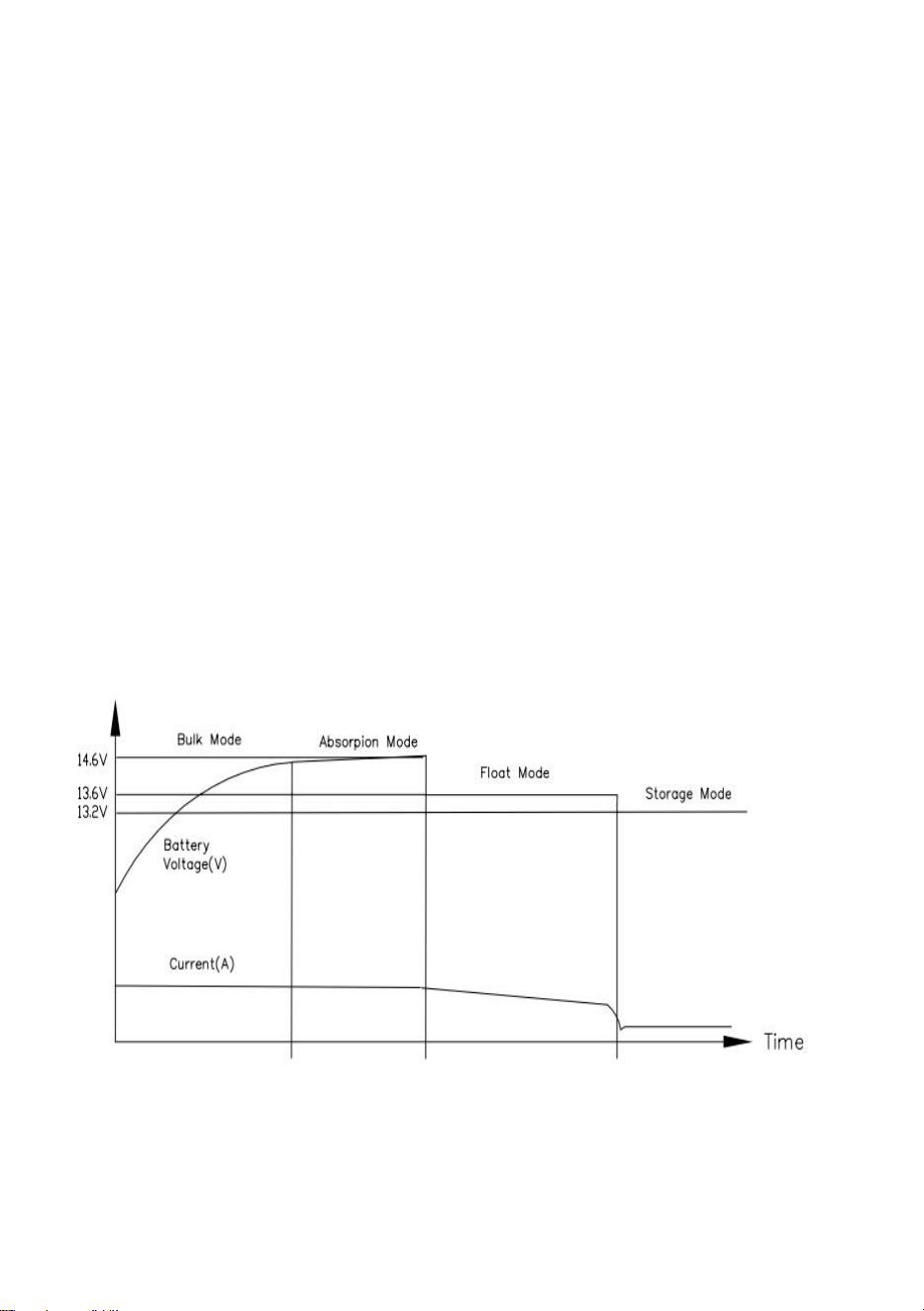
- 6 -
od tego, co nastąpi wcześniej, ładowarka przejdzie w tryb zbiorczy.
Dioda LED1 świeci na zielono. Napięcie ładowania wynosi około 13,6 V.
Jeżeli prąd ładowania przekracza 50% maksymalnego prądu
wyjściowego przez ponad 30 sekund, ładowarka ponownie przejdzie w
tryb zbiorczy i rozpocznie nowy cykl ładowania. Jeśli ładowarka
pozostanie w trybie Absorpcji przez 48 godzin, przejdzie w tryb
Przechowywania.
Przetłumaczone za pomocą (wersja darmowa) .
(24)Ładowanie podtrzymujące, które służy do utrzymywania świeżości
akumulatora („przechowywanie”)
w okresach bezczynności obciążenia. Ładowarka automatycznie
zmienia tryby, aby dostosować się do zmian warunków. Dioda LED1
świeci na zielono, a napięcie ładowania wynosi około 13,2 V, a napięcie
może się różnić w zależności od akumulatora. Jeśli prąd ładowania
przekroczy 50% maksymalnego prądu wyjściowego przez ponad 30
sekund, ładowarka ponownie przejdzie do ładowania prądem stałym i
rozpocznie nowy cykl ładowania.
Rysunek 1
75.Bateria litowa 3-STOPNIOWY TRYB ŁADOWANIA :
Dioda LED2 świeci na niebiesko. Tryb ten zapewnia automatyczny
system ładowania w trzech krokach . (Rysunek 2)
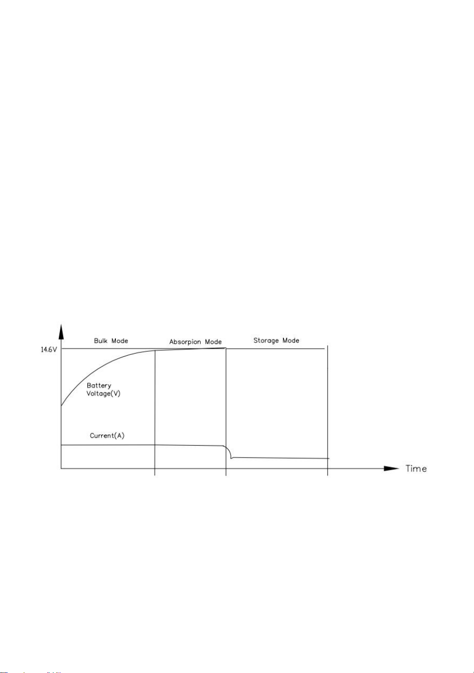
- 7 -
(16)Szybkie ładowanie umożliwiające przywrócenie pełnego napięcia
sprawnego, rozładowanego akumulatora
szybko.LED2 niebieski LED4 czerwony.
(17)Standardowe ładowanie umożliwiające pełne naładowanie
akumulatora w bezpiecznym tempie
przedłużyć żywotność akumulatora i zapewnić zasilanie oświetlenia 12V
oraz urządzeń znajdujących się w pojeździe/urządzeniu
(„Absorpcja”).LED2 niebieska LED4 czerwona.Napięcie ładowania
ustawione jest na 14,6V .
(18)Gdy prąd ładowania absorpcyjnego jest mniejszy niż 15% wartości
maksymalnej
prąd wyjściowy, ładowarka przejdzie w tryb przechowywania. .LED2
niebieski . Napięcie ładowania jest ustawione na 14,6 V. Jeśli prąd
ładowania przekroczy 50% maksymalnego prądu wyjściowego przez
ponad 30 sekund, ładowarka ponownie wejdzie do modułu Bulk i
rozpocznie nowy cykl ładowania .
Rysunek 2
76.Tryb STAŁEGO NAPIĘCIA .
(11)Tego trybu można używać do bezpośredniego zasilania sprzętu 12 V
i/lub utrzymywania akumulatora przy tym napięciu .
(12)Aby ustawić tryb stały, przy wyłączonym urządzeniu, przesu ń

- 8 -
przełącznik A w prawo w położenie
Pozycję „Stałe napięcie” i podłącz urządzenie do źródła zasilania 120
V, niebieska dioda LED2 świeci się, dioda LED3 świeci się na pomarań
czowo. Delikatnie obróć potencjometr regulacji napięcia wyjściowego w
lewo lub w prawo, aby wyregulować napięcie w zakresie 13-16,5 V.
Uwaga: Teraz przy każdym włączeniu urządzenia ustawione napięcie
wyjściowe zostanie ustalone na już ustawionej wartości napięcia.
77.Przełącznik A i Przełącznik B: Przełącznik A to trójsegmentowy
przełącznik wyboru
wybiera tryb kwasowy/tryb stałej mocy wyjściowej/tryb litowy od lewej do
prawej. Przełącznik B to regulowany potencjometr, który reguluje zakres
napięcia wyjściowego 13,0 V-16,5 V w kierunku zgodnym z ruchem
wskazówek zegara w stanie trybu stałego wyjścia (przełącznik B nie jest
regulowany w trybie kwasowym/trybie litowym). (Rysunek 3).

- 9 -
Rysunek 3
78.Wskaźniki LED: LED1 Zielone światło wskazuje tryb pracy na baterii
kwasowej. LED2
Niebieskie światło wskazuje tryb baterii litowej. LED3 LED3 Pomara ń
czowe światło wskazuje tryb pracy na baterii półprzewodnikowej lub tryb
wyjścia krajowego. LED2 Niebieskie światło wskazuje tryb pracy na
baterii litowej.LED3 Pomara ń czowe światło wskazuje tryb pracy na
akumulatorze półprzewodnikowym lub tryb wyjścia o stałym
napięciu.LED4 Czerwone światło wskazuje ładowanie, zgaszone
oznacza koniec ładowania lub tryb gotowości. (Rysunek 3).
UWAGA: Przed wyjęciem i wymianą konwertera/ładowarki wykonaj
następujące kontrole:
Odłącz zasilanie sieciowe od pojazdu/urządzenia .
Odłącz przewody od dodatniego + wyjściowego przewodu łączącego
przetwornik.
Ponownie podłącz zasilanie prądem przemiennym, aby zasilić
- 10 -
konwerter .
Za pomocą woltomierza zmierz napięcie na wyjściu przetwornika - i +
Terminale :
Jeśli odczyt napięcia mieści się w przedziale od 13 VDC do 14 VDC
(zwykle 13,6 VDC) ,
jednostka jest normalna. W przeciwnym razie postępuj zgodnie z ogólną
przyczyną usterki i tabelą rozwiązywania problemów .
PARAMETER SPECIFICATIONS
wydarzenie sportowe
parametry
Moc wejściowa
AC 120 V 60 Hz
Maksymalny prąd
wyjściowy
55A
napięcie wyjściowe
tryb stały: 13-16,5 V
akumulator kwasowo-ołowiowy : 12-14,6 V
Lit bateria : 12-14,6 V
GENERAL PROBLEM TROUBLESHOOTING
zjawisko usterki
Rozwiązania ogólne
Brak wyjścia prądu
stałego
Zasilanie 120 VAC nie jest podłączone do autokaru lub
wyłącznik prądu przemiennego autokaru jest w pozycji
wyłączonej .
Przepala się odwrócony bezpiecznik akumulatora.
(Odwrócona polaryzacja baterii)
Jeśli obciążenie jest poważnie przeciążone lub zwarte,
należy odłączyć wszystkie obciążenia, a następnie
ponownie włączyć zasilanie.
Konwerter włącza się i
wyłącza
Przepływ powietrza wentylatora jest niewystarczający
lub zablokowany. (wymagana minimalna wolna
przestrzeń 1” na każdym końcu) .

- 11 -
Przepala się bezpiecznik
prądu stałego
Bateria ma odwróconą polaryzację
Wyjście 12 VDC jest zbyt
niskie
Uszkodzona bateria, możliwe złe ogniwa
Dioda LED nie jest
włączona
Bateria jest w pełni naładowana
Napięcie akumulatora jest wysokie, a maksymalne
napięcie wyjściowe ładowarki
Uwaga : Jeśli po sprawdzeniu zgodnie z powyższymi metodami konwerter
nadal nie działa prawidłowo, skontaktuj się ze sprzedawcą w celu
rozwiązania problemu i nie demontuj konwertera w celu naprawy bez
autoryzacji .
LIST OF ACCESSORIES
11.instrukcja obsługi *1
12.Śrubokręt *1
Producent: Shanghaimuxinmuyeyouxiangongsi
Adres: Shuangchenglu 803nong11hao1602A-1609shi, baoshanqu, szanghaj
200000 CN.
Import do AUS: SIHAO PTY LTD, 1 ROKEVA STREETEASTWOOD NSW
2122 Australia
Import do USA: Sanven Technology Ltd., Suite 250, 9166 Anaheim Place,
Rancho Cucamonga, CA 91730

- 12 -
REP
EC
E-CrossStu GmbH
Mainzer Landstr.69, 60329 Frankfurt am Main.
REP
UK
YH CONSULTING LIMITED.
C/O YH Consulting Limited Office 147, Centurion House,
London Road, Staines-upon-Thames, Surrey, TW18 4AX


Technisch Ondersteuning en e-garantiecertificaat
www.vevor.com/support
AC-DC gelijkrichter/oplader voor campers
Handleiding
Model: GS800RVP-55
We continue to be committed to provide you tools with competitive price.
"Save Half", "Half Price" or any other similar expressions used by us only represents an
estimate of savings you might benefit from buying certain tools with us compared to the major
top brands and does not necessarily mean to cover all categories of tools offered by us. You
are kindly reminded to verify carefully when you are placing an order with us if you are
actually saving half in comparison with the top major brands.

- 1 -
MODEL: GS800RVP-55
Have product questions? Need technical support? Please feel free to
contact us:
Technical Support and E-Warranty Certificate
www.vevor.com/support
NEED HELP? CONTACT US!
This is the original instruction, please read all manual instructions
carefully before operating. VEVOR reserves a clear interpretation of our
user manual. The appearance of the product shall be subject to the
product you received. Please forgive us that we won't inform you again if
there are any technology or software updates on our product.
AC-DC Rectifier /
Charger for RV
- 2 -
Waarschuwing-Om het risico op letsel te verminderen, moet de
gebruiker de handleiding zorgvuldig lezen.
Dit apparaat voldoet aan Deel 15 van de FCC-regels. Het gebruik is
onderworpen aan de volgende twee voorwaarden: (1) Dit apparaat
mag geen schadelijke interferentie veroorzaken, en (2) dit apparaat
moet alle ontvangen interferentie accepteren, inclusief interferentie
die een ongewenste werking kan veroorzaken.
Dit product valt onder de bepalingen van de Europese richtlijn
2012/19/EG. Het symbool met een doorgestreepte afvalcontainer
geeft aan dat het product in de Europese Unie een aparte
afvalinzameling vereist. Dit geldt voor het product en alle
accessoires die met dit symbool zijn gemarkeerd. Producten die als
zodanig gemarkeerd zijn, mogen niet bij het normale huisvuil worden
weggegooid, maar moeten naar een inzamelpunt voor recycling van
elektrische en elektronische apparaten worden gebracht
SAFETY WARNINGS
LEES VOOR UW VEILIGHEID ALLE INSTRUCTIES VOORDAT
INSTALLATIE EN BEDIENING .
INSTALLATEUR :GEEF DEZE INSTRUCTIES AAN DE EINDGEBRUIKER OF
Consumeer .
CONSUMENT :BEWAAR DEZE INSTRUCTIES VOOR TOEKOMSTIG
GEBRUIK.
LET OP : PRODUCTEN MOGEN NIET WORDEN GEBRUIKT EN HEBBEN
GEEN GARANTIE
RUIMTEVAART-, MEDISCHE OF LEVENSVEILIGHEIDSTOEPASSINGEN.
WAARSCHUWING
–
VOORKOM PERSOONLIJK LETSEL OF
PRODUCTSCHADE.
ER IS 120 VAC AANWEZIG. DEZE CONVERTER/OPLADER IS ONTWORPEN
OM

- 3 -
CONVERTEERT 120 VAC NAAR 12 VDC. HET BIEDT OOK
LAAGSPANNINGSVERMOGEN VOOR HET OPLADEN VAN INGEBOUWDE
12 VDC-BATTERIJEN. DE CONVERTER/LADER IS VAN HET TYPE
“ SWITCH MODE ” EN IS ONTWORPEN
ONDERHOUDSVRIJ TE ZIJN, ZONDER DAT DE GEBRUIKER ER
ONDERHOUD AAN HOEFT UIT TE VOEREN
COMPONENTEN. HET UITGANGSVERMOGEN VAN DE
CONVERTER/LADER I
“ STROOMBEGRENZING ” DOOR ONTWERP.
BEWAAR ELEKTRISCHE APPARATEN NOOIT IN COMPARTIMENTEN WAAR
ER ZIJN BRANDBARE VLOEISTOFFEN (ZOALS BENZINE).
MONTEER/INSTALLEER HET APPARAAT NIET IN COMPARTIMENTEN DIE
ZIJN ONTWORPEN VOOR DE OPSLAG VAN BATTERIJEN MET
BRANDBARE VLOEISTOFFEN.
INSTALLATION INSTRUCTIONS
De AC-DC-converter/lader heeft drie modi: opladen van zuurbatterijen
en lithiumbatterijen en vaste output.
79.Koppel de POS (+)-draad van de accu aan het uiteinde van de accu los
voordat u deze converter/oplader aansluit op de bedrading van een
voertuig/apparaat
80.De installatielocatie kan zich op elk intern oppervlak (niet beïnvloed
door direct weer) bevinden. De geselecteerde locatie moet na
onderstaande uren Installatie bereikbaar zijn. Bij installatie in een kast
moet de kast groot genoeg zijn om de warme lucht af te voeren. Zorg
ervoor dat er aan elk uiteinde van het apparaat minimaal 1 inch (1 inch)
vrije luchtruimte is, zodat de koellucht normaal door het apparaat kan
stromen. Vermijd verontreinigingen zoals vuil aan de rand,
metaaldeeltjes of vocht.
81.Er zijn flenzen met gaten meegeleverd voor eenvoudige montage met
standaard bevestigingsmiddelen. Controleer of het oppervlak waarop de
omvormer is gemonteerd stevig is en het gewicht (6 lbs) kan dragen

- 4 -
tijdens gebruik van het voertuig .
82.Het 120 VAC-stopcontact moet zich binnen een straal van 90 cm van de
converter/oplader bevinden om stroom te leveren. Er moet ook rekening
worden gehouden met elektrische overwegingen bij montage in de buurt
van de locaties van de accu's en het 12-volt DC-verdeelpaneel.
83.Zorg ervoor dat u alle verbindingen stevig vastdraait. Een losse
verbinding kan er snel voor zorgen dat aansluitingen en draden
oververhit raken. Bekijk de unitlabels voor de aanbevolen
klemmomentwaarden.
84.De fan zal niet de hele tijd draaien. De ventilator is temperatuurgeregeld
en werkt alleen wanneer dat nodig is.
85.Eenmaal aangesloten, laat het apparaat nooit onbeheerd achter.
86.Alle producten moeten worden geïnstalleerd door een gecertificeerde
elektricien .
WAARSCHUWING : Voorkom mogelijk letsel of overlijden .
120 VAC-aansluiting : Controleer eerst of de 120 VAC-stroombron AC
stroomonderbreker(s) staan in de uit-stand. Schakel
AC-stroomonderbrekers NIET in voordat de installatie is voltooid .
Met behulp van een 8 AWG koperdraad met minimale maat, bevestig
vanaf de
voertuig-/apparaatchassis aan op de verbindingsnok van de
converter/lader. Sluit het aangesloten netsnoer op de converter/oplader
stevig aan op de 120 V AC-contactdoos .
12 V DC Bedrading - Het is belangrijk om de juiste draaddikte te
gebruiken. Gebruik een
minimaal koperdraad van 8 AWG-formaat.
(19)De terminal gemarkeerd met + of POS is voor de RV 12VDC positieve
aansluiting .
(20)De terminal gemarkeerd met - of NEG is voor de negatieve
RV12VDC-aansluiting.
(21)De 12VDC-uitgangsbedrading vereist geen overstroombeveiliging
omdat de converter/oplader de stroomuitvoer beperkt. Alle elektrische

- 5 -
aansluitingen moeten echter voldoen aan de toepasselijke NEC-code .
87.Loodzuuraccumodus :
Ga naar deze modus LED1 licht groen op. Deze modus biedt een
automatisch laadsysteem via vier modi. (Figuur 1).
(25)Constante stroom snelladen (Bulk Mode), zodat er voldoende stroom
is
uitgeput en herstel snel de volledige spanning, LED1 is heldergroen,
LED4 is helderrood.
(26)Wanneer de accuspanning ongeveer 14,6 V bereikt, wordt deze
constant
spanningslaadmodus (Absorpion Mode) op een veilige snelheid om de
levensduur van de batterij en de voeding te verlengen. LED1 Groen
LED4 Rood.
(27)Wanneer de laadstroom minder dan 15% van het maximale vermogen
bedraagt
stroom of wanneer de oplader gedurende 4 uur is opgeladen, afhankelijk
van wat zich het eerst voordoet, gaat de oplader naar de bulkmodus.
LED1 is groen. De laadspanning bedraagt ongeveer 13,6 V. Als de
laadstroom gedurende meer dan 30 seconden 50% van de maximale
uitgangsstroom overschrijdt, gaat de lader opnieuw naar de Bulk-modus
en begint een nieuwe laadcyclus. Als de lader 48 uur in de
Absorb-modus blijft, gaat hij naar de Storage-modus.
Vertaald met (gratis versie) .
(28)Druppelladen, dat wordt gebruikt om de batterij fris te houden
("opslag")
tijdens perioden van inactiviteit van de belasting. De lader verandert
automatisch van modus om veranderingen in de omstandigheden aan te
passen. LED1 is groen en de laadspanning bedraagt ongeveer 13,2 V.
De spanning kan variëren afhankelijk van de accu. Als de laadstroom
gedurende meer dan 30 seconden de 50% van de maximale
uitgangsstroom overschrijdt, zal de lader opnieuw overgaan op het laden
met constante stroom en een nieuwe laadcyclus starten.
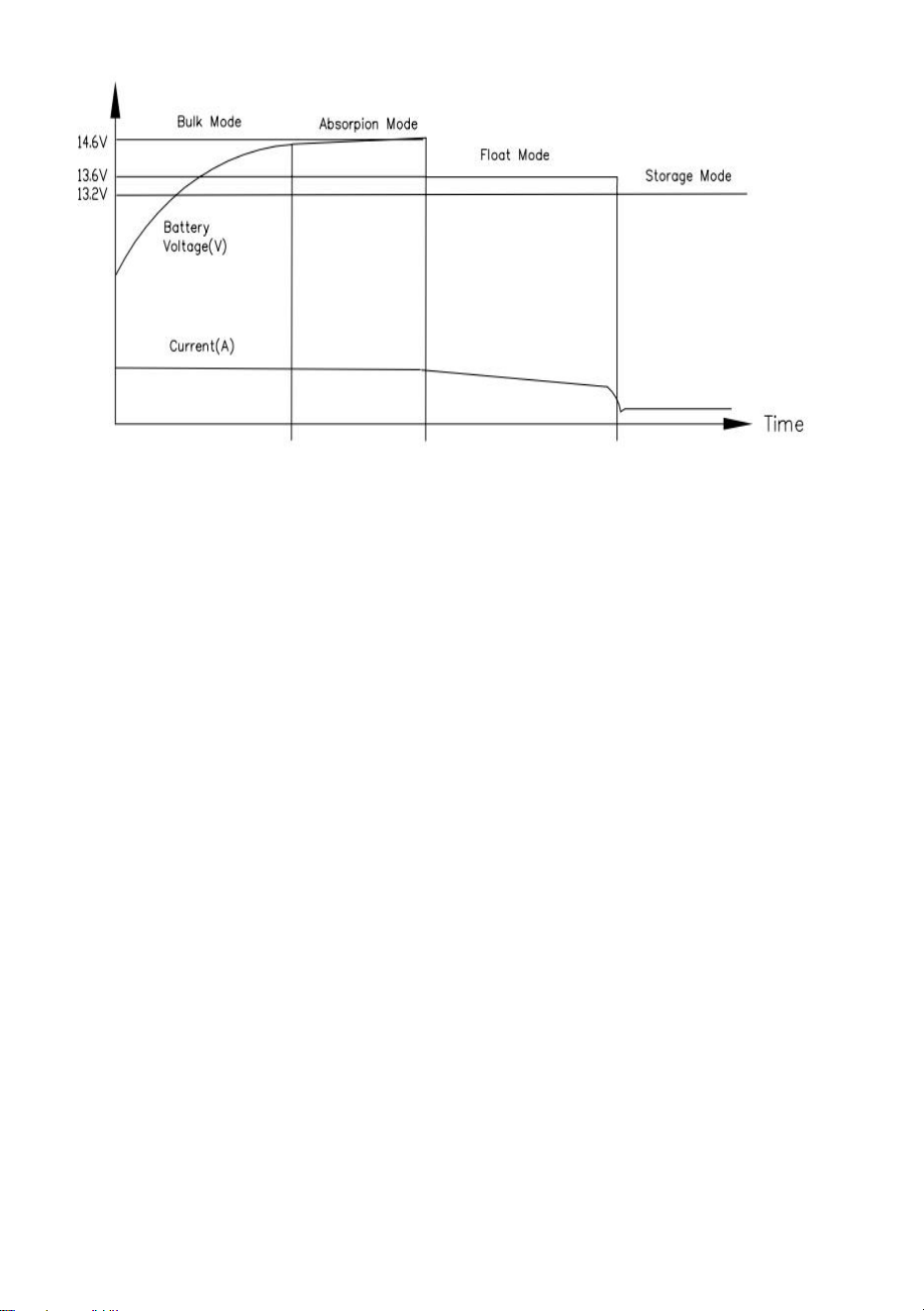
- 6 -
Figuur 1
88.Lithiumbatterij 3-FASEN OPLAADMODUS :
LED2 brandt blauw. Deze modus biedt een automatisch laadsysteem in
drie stappen . (Figuur 2)
(19)Een snelle lading om een goede, lege batterij weer op volle spanning
te brengen
snel.LED2 blauw LED4 rood.
(20)Een standaardlading om de batterij tegen een veilig tarief volledig op te
laden
verlengt de levensduur van de accu en levert stroom voor de
12V-verlichting en apparaten in het voertuig/apparaat ("Absorptie").
LED2 blauw LED4 rood. De laadspanning is ingesteld op 14,6 V.
(21)Wanneer de absorptielaadstroom minder dan 15% van het maximum
bedraagt
uitgangsstroom, zal de lader naar de opslagmodus gaan. .LED2 blauw .
De laadspanning is ingesteld op 14,6V. Als de laadstroom langer dan 30
seconden de 50% van de maximale uitgangsstroom overschrijdt, zal de
lader opnieuw de bulk ingaan en een nieuwe laadcyclus starten .

- 7 -
Figuur 2
89.VASTE SPANNING-modus .
(13)Deze modus kan worden gebruikt om 12 volt apparatuur rechtstreeks
van stroom te voorzien en/of de accu op die spanning te houden .
(14)Om de vaste modus in te stellen terwijl het apparaat is uitgeschakeld,
verplaatst u schakelaar A naar rechts naar de
"Vaste spanning" positie en sluit het apparaat aan op een 120V-voeding,
LED2 blauw aan LED3 oranje aan. Draai de
uitgangsspanningsinstelpotentiometer voorzichtig tegen de klok in of
met de klok mee om de spanning binnen het bereik van 13-16,5V aan te
passen.
Opmerking: Elke keer dat het apparaat wordt ingeschakeld, wordt de
door u ingestelde uitgangsspanning vastgezet op de reeds aangepaste
spanningswaarde.
90.Schakelaar A en schakelaar B: Schakelaar A is een keuzeschakelaar
met drie segmenten
selecteert Acid Mode/Fixed Output Mode/Lithium Mode van links naar
rechts. Schakelaar B is een instelbare potentiometer die het
uitgangsspanningsbereik van 13,0 V-16,5 V met de klok mee aanpast in
de vaste uitgangsmodus (schakelaar B is niet instelbaar in de
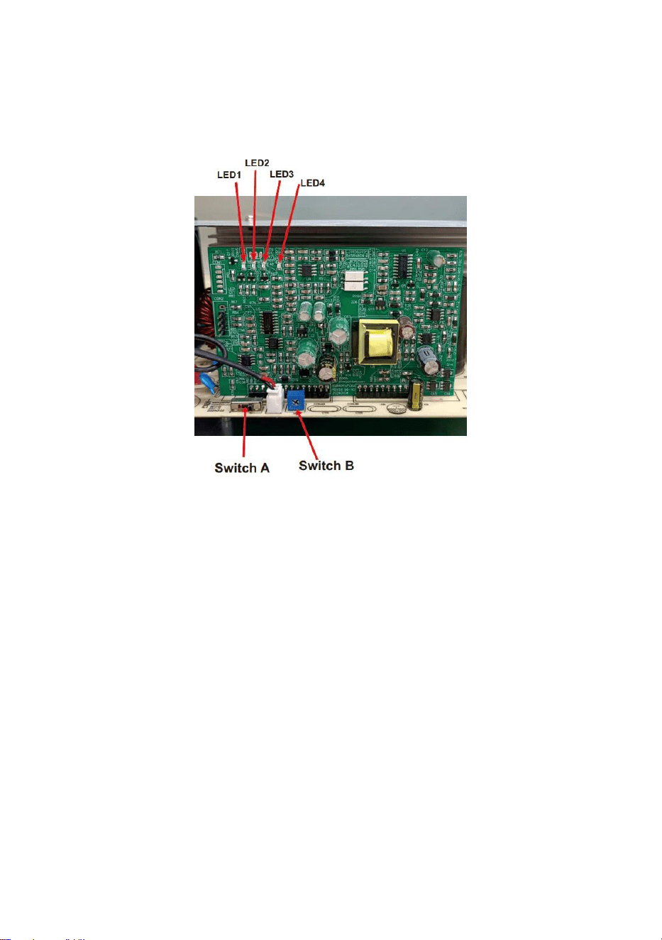
- 8 -
zuurmodus/lithiummodus). (Figuur 3).
figuur 3
91.LED-indicatoren: LED1 Groen licht geeft de zuurbatterijmodus aan.
LED2
Blauw licht geeft de lithiumbatterijmodus aan. LED3 LED3 Oranje lampje
geeft de solid-state batterijmodus of de landuitvoermodus aan. LED2
Blauw licht geeft de lithiumbatterijmodus aan. LED3 Oranje licht geeft de
solid-state batterijmodus of vaste spanningsuitgangsmodus aan. LED4
Rood licht geeft aan dat het opladen is voltooid, uit geeft het einde van
het opladen of stand-by aan. (Figuur 3).
OPMERKING: Voer de volgende controles uit voordat u de
converter/oplader verwijdert en vervangt:
Ontkoppel de wisselstroom van het voertuig/apparaat .
Ontkoppel de bedrading van de positieve + uitgangsverbindingslijn van
de
- 9 -
omvormer.
Sluit de wisselstroom opnieuw aan om de omvormer van stroom te
voorzien .
Meet met behulp van een voltmeter de spanning op de converter - en +
uitgang
Terminals :
Als de spanningswaarde tussen 13 VDC en 14 VDC ligt (meestal 13,6
VDC) ,
het apparaat is normaal. Volg anders de algemene foutoorzaak- en
probleemoplossingstabel .
PARAMETER SPECIFICATIONS
sportevenement
parameters
Ingangsvermogen
Wisselstroom 120 V 60 Hz
Maximale uitgangsstroom
55A
uitgangsspanning
vaste modus: 13-16,5V
loodzuuraccu : 12-14,6 V
Lithium batterij : 12-14,6 V
GENERAL PROBLEM TROUBLESHOOTING
fout fenomeen
Algemene oplossingen
Geen DC-uitgang
120 VAC niet aangesloten op de bus of de
AC-stroomonderbreker van de bus staat in de
uit-stand .
De omgekeerde batterijzekering springt door.
(Batterijpolariteit omgekeerd)
Als de belasting ernstig overbelast of kortgesloten is,
verwijder dan alle belastingen en start vervolgens de
voeding opnieuw op.
Convertercycli Aan en Uit
De luchtstroom van de ventilator is onvoldoende of

- 10 -
geblokkeerd. (minimale vrije luchtruimte van 1 inch
aan elk uiteinde vereist) .
De DC-zekering springt
De batterij heeft omgekeerde polariteit
12 VDC-uitgang is te laag
Defecte batterij, mogelijk slechte cellen
LED-lampje brandt niet
De batterij is volledig opgeladen
De accuspanning is hoog en de maximale
uitgangsspanning van de lader
Opmerking : Als de omvormer na controle volgens de bovenstaande
methoden nog steeds niet goed werkt, neem dan contact op met de dealer
om het probleem op te lossen en demonteer de omvormer niet zonder
toestemming voor reparatie .
LIST OF ACCESSORIES
13.handleiding *1
14.Schroevendraaier *1
Fabrikant: Shanghaimuxinmuyeyouxiangongsi
Adres: Shuangchenglu 803nong11hao1602A-1609shi, baoshanqu, shanghai
200000 CN.
Geïmporteerd naar AUS: SIHAO PTY LTD, 1 ROKEVA
STREETEASTWOOD NSW 2122 Australië
Geïmporteerd naar de VS: Sanven Technology Ltd., Suite 250, 9166
Anaheim Place, Rancho Cucamonga, CA 91730

- 11 -
REP
EC
E-CrossStu GmbH
Mainzer Landstr.69, 60329 Frankfurt am Main.
REP
UK
YH CONSULTING LIMITED.
C/O YH Consulting Limited Office 147, Centurion House,
London Road, Staines-upon-Thames, Surrey, TW18 4AX


Teknisk Support och e-garanticertifikat
www.vevor.com/support
AC-DC Likriktare/laddare för husbil
Instruktionsmanual
Modell: GS800RVP-55
We continue to be committed to provide you tools with competitive price.
"Save Half", "Half Price" or any other similar expressions used by us only represents an
estimate of savings you might benefit from buying certain tools with us compared to the major
top brands and does not necessarily mean to cover all categories of tools offered by us. You
are kindly reminded to verify carefully when you are placing an order with us if you are
actually saving half in comparison with the top major brands.

- 1 -
MODELL: GS800RVP-55
Have product questions? Need technical support? Please feel free to
contact us:
Technical Support and E-Warranty Certificate
www.vevor.com/support
NEED HELP? CONTACT US!
This is the original instruction, please read all manual instructions
carefully before operating. VEVOR reserves a clear interpretation of our
user manual. The appearance of the product shall be subject to the
product you received. Please forgive us that we won't inform you again if
there are any technology or software updates on our product.
AC-DC Rectifier /
Charger for RV
- 2 -
Varning - För att minska risken för skada måste användaren läsa
instruktionerna noggrant.
Denna enhet uppfyller del 15 av FCC-reglerna. Driften är föremål för
följande två villkor: (1) Den här enheten får inte orsaka skadliga
störningar och (2) den här enheten måste acceptera alla mottagna
störningar, inklusive störningar som kan orsaka oönskad funktion.
Denna produkt omfattas av bestämmelserna i det europeiska
direktivet 2012/19/EC. Symbolen som visar en soptunna korsad
anger att produkten kräver separat sophämtning i EU. Detta gäller för
produkten och alla tillbehör märkta med denna symbol. Produkter
märkta som sådana får inte slängas tillsammans med vanligt
hushållsavfall, utan måste lämnas till en insamlingsplats för
återvinning av elektriska och elektroniska apparater
SAFETY WARNINGS
FÖR DIN SÄKERHET, LÄS ALLA INSTRUKTIONER INNAN
INSTALLATION OCH DRIFT .
INSTALLATÖR : GE DESSA INSTRUKTIONER TILL SLUTANVÄNDAREN
ELLER
konsumera .
KONSUMENT : SPARA DESSA INSTRUKTIONER FÖR FRAMTIDA
REFERENS.
ANMÄRKNING : PRODUKTERNA SKA INTE ANVÄNDAS ELLER
GARANTERAS I
FLYG-, MEDICINSKA ELLER LIVSSÄKERHETSAPPLIKATIONER.
VARNING
–
UNDVIK PERSONSKADA ELLER PRODUKTSKADA.
120 VAC FINNS. DENNA OMVANDLARE/LADDARE ÄR DESIGNAD FÖR ATT
KONVERTERA 120 VAC TILL 12 VDC. DEN GER OCKSÅ
LÅGSPÄNNINGSSTRÖM FÖR LADDNING AV INBYGGDA 12
VDC-BATTERIER. OMVANDLAREN/LADDAREN ÄR AV TYPEN "

- 3 -
VÄXLINGSLÄGE " OCH ÄR DESIGNAD
ATT VARA UNDERHÅLLSFRI UTAN ATT ANVÄNDAREN KAN REPARERA
KOMPONENTER. OMVANDLAREN/LADDARENS UTEFFEKT I
" STRÖMBEGRÄNSNING " AV DESIGN.
FÖRVARA ALDRIG ELEKTRISKA APPARATER I FACK DÄR
BRANDFARLIGA VÄTSKOR (SOM BENSIN) FINNS.
MONTERA/INSTALLERA INTE ENHETEN I FACK AVSEDDA FÖR
FÖRVARING AV BATTERIER MED BRANDFARLIGA VÄTSKOR.
INSTALLATION INSTRUCTIONS
AC-DC-omvandlaren/laddaren har tre lägen: surt batteri och
litiumbatteriladdning och fast utgång.
92.Koppla bort batteriets POS-kabel (+) vid batteriänden innan du ansluter
denna omvandlare/laddare till alla kablar för fordon/enheter
93.Installationsplatsen kan placeras på vilken inre yta som helst
(opåverkad av direkt väder). Den valda platsen måste vara tillgänglig
efter följande timmar Installation. När det installeras inuti ett skåp måste
skåpet vara tillräckligt stort för att avleda varm luft. Se till att det finns
minst 1 tum (1 tum) fritt luftutrymme i varje ände av enheten så att kylluft
kan passera genom enheten normalt. Undvik föroreningar som perifer
smuts, metallpartiklar eller fukt.
94.Flänsar med hål tillhandahålls för enkel montering med standardfästen.
Kontrollera att ytan som omvandlaren är monterad på är solid och håller
vikten (6 lbs) under fordonets drift .
95.120 VAC-uttaget måste placeras inom 36 tum från
omvandlaren/laddaren för att förse ström. Elektrisk hänsyn bör också tas
till montering i närheten av batterierna och 12-volts
DC-distributionspanelen.
96.Se till att dra åt alla anslutningar ordentligt. En lös anslutning kan
snabbt göra att terminaler och ledningar överhettas. Granska
enhetsetiketterna för rekommenderade vridmomentvärden.
97.De fläkt kommer inte att springa hela tiden. Fläkten är temperaturstyrd

- 4 -
och fungerar endast vid behov.
98.När den väl är ansluten, lämna aldrig enheten utan uppsikt.
99.Alla produkter måste installeras av en certifierad elektriker .
VARNING : Undvik möjlig skada eller dödsfall .
120 VAC-anslutning : Kontrollera först att 120 VAC-strömkällan AC
strömbrytare är i avstängt läge. Slå INTE på AC-strömbrytare förrän
installationen är klar .
Använder en 8:a AWG minsta storlek koppartråd, fäst från
fordons-/enhetschassi till omvandlaren/laddarens kopplingsanordning.
Använd den medföljande nätsladden på omvandlaren/laddaren och
anslut ordentligt till 120 V AC-uttag .
12 VDC Kabeldragning - Det är viktigt att använda rätt trådmått. Använda
en
minst 8 AWG storlek koppartråd.
(22)Terminalen märkt + eller POS är för RV 12VDC positiv anslutning .
(23)Terminalen märkt - eller NEG är för RV12VDC negativ anslutning.
(24)12VDC-utgångsledningarna kräver inget överströmsskydd
eftersom omvandlaren/laddaren begränsar strömutgången. Alla
elektriska anslutningar måste dock överensstämma med lämplig
NEC-kod .
100.Bly-syra batteriläge :
Gå in i detta läge LED1 lyser grönt. Detta läge ger ett automatiskt
laddningssystem genom fyra lägen.(Figur 1).
(29)Konstant ström snabb laddning (Bulk Mode), så att strömmen är
utmattad och snabbt återställa full spänning, LED1 lyser grönt, LED4
lyser rött.
(30)När batterispänningen når cirka 14,6V går den in i konstanten
spänningsladdningsläge (Absorpion Mode) i en säker takt för att förlänga
livslängden på batteriet och strömförsörjningen. LED1 Grön LED4 Röd.
(31)När laddningsströmmen är mindre än 15 % av den maximala
uteffekten
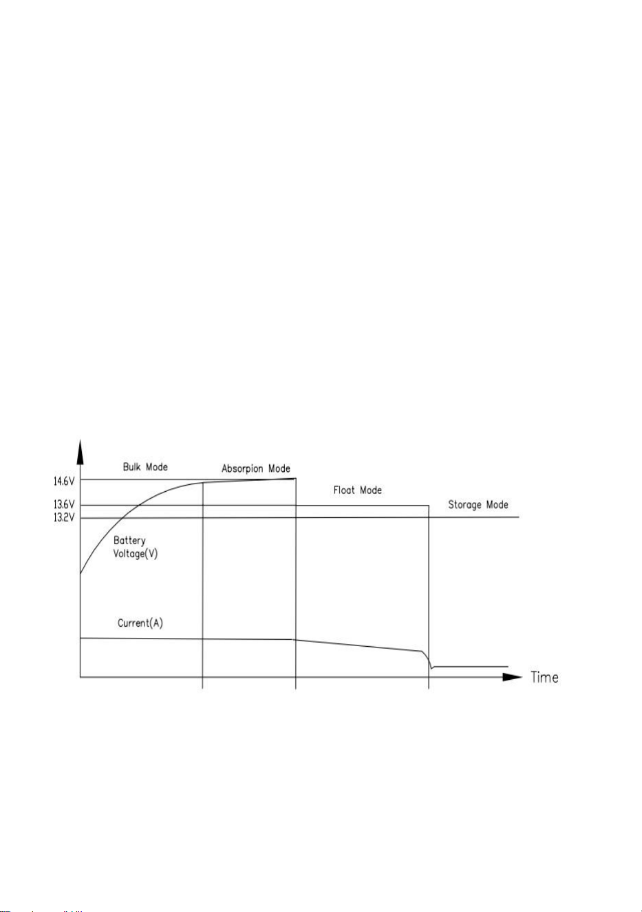
- 5 -
ström eller när laddaren har laddats i 4 timmar, beroende på vad som
inträffar först, går laddaren in i Bulk Mode. LED1 lyser grönt.
Laddningsspänningen är cirka 13,6 V. Om laddningsströmmen
överstiger 50 % av den maximala utströmmen i mer än 30 sekunder,
kommer laddaren att återgå till Bulk-läge och påbörja en ny
laddningscykel. Om laddaren förblir i Absorb-läge i 48 timmar, går den in
i lagringsläge.
Översatt med (gratisversion) .
(32)Underhållsladdning, som används för att hålla batteriet fräscht
("lagring")
under perioder av inaktivitet. Laddaren ändrar automatiskt lägen för att
anpassa sig till förändringar i förhållandena. LED1 lyser grönt och
laddningsspänningen är cirka 13,2V, och spänningen kan variera
beroende på batteri. Om laddningsströmmen överstiger 50 % av den
maximala utströmmen i mer än 30 sekunder, kommer laddaren att
återgå till konstant strömladdning och starta en ny laddningscykel.
Figur 1
101.Litiumbatteri 3 STEGS LADDNINGSLÄGE :
LED2 lyser blått. Detta läge ger ett automatiskt laddningssystem i tre
steg .(Figur 2)
(22)En snabbladdning för att få ett bra, urladdat batteri tillbaka till full
spänning
- 6 -
snabbt.LED2 blå LED4 röd.
(23)En standardladdning för att få upp batteriet till full laddning till en säker
takt
förläng batteriets livslängd och ge ström för att driva 12V belysning och
apparater i fordonet/enheten ("Absorption").LED2 blå LED4
röd.Laddspänningen är inställd på 14,6V .
(24)När Absorptionsladdningsströmmen är mindre än 15 % av max
utström, laddaren går in i lagringsläge. .LED2 blå .
Laddningsspänningen är inställd på 14,6V. Om laddningsströmmen
överstiger 50 % av den maximala utströmmen i mer än 30 sekunder,
kommer laddaren att gå in i Bulken igen och starta en ny
laddningscykel .
figur 2
102.FAST SPÄNNING Läge .
(15)Detta läge kan användas för att direkt driva 12-voltsutrustning och eller
hålla batteriet vid den spänningen .
(16)För att ställa in fast läge, med enheten avstängd, flytta omkopplaren A
åt höger till
"Fixed Voltage" position och anslut enheten till en 120V strömkälla,
LED2 blå på LED3 orange på. Vrid försiktigt
utspänningsjusteringspotentiometern moturs eller medurs för att justera
spänningen inom området 13-16,5V.
- 7 -
Notera: Nu, varje gång enheten slås på, kommer utspänningen du
ställer in att vara fixerad till det redan justerade spänningsvärdet.
103.Switch A och Switch B: Switch A är en tresegmentsväljare som
väljer Acid Mode/Fixed Output Mode/Lithium Mode från vänster till höger.
Switch B är en justerbar potentiometer som justerar 13,0V-16,5V
utspänningsområdet från medurs i det fasta utgångsläget (omkopplaren
B är inte justerbar i surt läge/litiumläge). (Figur 3).
Figur 3
104.LED-indikatorer: LED1 Grönt ljus indikerar surt batteriläge. LED2
Blått ljus indikerar litiumbatteriläge. LED3 LED3 Orange ljus indikerar
halvledarbatteriläge eller landsutgångsläge. LED2 Blått ljus indikerar
litiumbatteriläge.LED3 Orange ljus indikerar halvledarbatteriläge eller
fast spänningsutgångsläge.LED4 Rött ljus indikerar laddning, av
indikerar slut på laddning eller standby. (Figur 3).
- 8 -
OBS: Innan du tar bort och sätter tillbaka omvandlaren/laddaren ska du
utföra följande kontroller:
Koppla bort nätströmmen från fordonet/enheten .
Koppla bort kablarna från den positiva + utgångsanslutningen på
omvandlare.
Återanslut nätströmmen för att strömsätta omvandlaren .
Använd en voltmeter och mät spänningen vid omvandlaren - och
+-utgången
Terminaler :
Om spänningsavläsningen är mellan 13VDC och 14VDC (vanligtvis
13,6VDC) ,
enheten är normal. Följ annars den allmänna felorsak och
felsökningstabellen .
PARAMETER SPECIFICATIONS
Sport evenemang
parametrar
Ingångseffekt
AC 120V 60Hz
Maximal utström
55A
utspänning
fast läge: 13-16,5V
bly-syra batteri :12-14,6V
Litium batteri : 12-14,6V
GENERAL PROBLEM TROUBLESHOOTING
felfenomen
Allmänna lösningar
Ingen DC-utgång
120 VAC inte ansluten till buss eller bussens
AC-strömbrytare är i avstängt läge .
Den omvända batterisäkringen går. (Batteriets polaritet
omvänd)
Om lasten är allvarligt överbelastad eller kortsluten, ta

- 9 -
bort alla laster och starta sedan om
strömförsörjningen.
Omvandlaren går på och
av
Fläktens luftflöde är otillräckligt eller blockerat. (1”
minsta fritt luftutrymme i varje ände krävs) .
DC-säkringen går
Batteriet har omvänd polaritet
12 VDC-utgången är för
låg
Defekt batteri, eventuellt dåliga celler
LED-lampan är inte tänd
Batteriet är fulladdat
Batterispänningen är hög och laddaren maximal
utspänning
OBS : Om omvandlaren fortfarande inte fungerar korrekt efter kontroll
enligt ovanstående metoder , kontakta återförsäljaren för att lösa
problemet, och ta inte isär omvandlaren för reparation utan tillstånd.
LIST OF ACCESSORIES
15.bruksanvisning *1
16.Skruvmejsel *1
Tillverkare: Shanghaimuxinmuyeyouxiangongsi
Adress: Shuangchenglu 803nong11hao1602A-1609shi, baoshanqu,
shanghai 200000 CN.
Importerad till AUS: SIHAO PTY LTD, 1 ROKEVA STREETEASTWOOD
NSW 2122 Australien
Importerad till USA: Sanven Technology Ltd., Suite 250, 9166 Anaheim
Place, Rancho Cucamonga, CA 91730

- 10 -
REP
EC
E-CrossStu GmbH
Mainzer Landstr.69, 60329 Frankfurt am Main.
REP
UK
YH CONSULTING LIMITED.
C/O YH Consulting Limited Office 147, Centurion House,
London Road, Staines-upon-Thames, Surrey, TW18 4AX


