8750-WATT
INVERTER GENERATOR
Instruction Manual
IMPORTANT: Your new tool has been engineered and manufactured to WEN’s highest standards for dependability,
ease of operation, and operator safety. When properly cared for, this product will supply you years of rugged,
trouble-free performance. Pay close attention to the rules for safe operation, warnings, and cautions. If you use
your tool properly and for its intended purpose, you will enjoy years of safe, reliable service.
NEED HELP? CONTACT US!
Have product questions? Need technical support? Please feel free to contact us:
TECHSUPPOR[email protected]1-847-429-9263 (M-F 8AM-5PM CST)
For replacement parts and the most up-to-date instruction manuals, visit WENPRODUCTS.COM
MODEL DF875iX

CONTENTS
WELCOME 3
Specifications ................................................................................................... 3
Introduction ..................................................................................................... 4
SAFETY 5
General Safety Rules ........................................................................................ 5
Generator Safety Warnings .............................................................................. 7
BEFORE OPERATING 9
Unpacking & Packing List ................................................................................ 9
Know Your Generator ..................................................................................... 10
Assembly & Adjustments ............................................................................... 12
Generator Preparation .................................................................................... 14
OPERATION & MAINTENANCE 19
Starting the Generator .................................................................................... 19
Using the Generator ....................................................................................... 26
Shutting Off the Generator ............................................................................. 32
Maintenance ................................................................................................... 33
Transportation & Storage ............................................................................... 39
Troubleshooting Guide ................................................................................... 40
Wiring Diagram .............................................................................................. 42
Exploded View & Parts List ............................................................................ 43
Warranty Statement ....................................................................................... 51
2
To purchase accessories for your tool, visit WENPRODUCTS.COM
Weatherproof Generator Cover (Model 56409, GNC875)
Magnetic Oil Dipstick (Model GNA200)

3
SPECIFICATIONS
Model Number DF875iX
Surge (Starting) Wattage Gas: 8750W LPG: 7800W
Rated (Running) Wattage Gas: 7000W LPG: 6300W
Rated Voltage 120V / 240V AC
Phase Single
Frequency 60 Hz
Product Weight With Wheel Kit 140 lbs
Product Weight Without Wheel Kit 134.5 lbs
Product Dimensions With Wheel Kit 26.8 in. x 26.4 in. x 23.2 in.
Product Dimensions Without Wheel Kit 23.8 in. x 20.2 in. x 21.1 in.
GENERATOR
Engine Type 4 stroke, OHV, single cylinder with forced air cooling system
Engine Displacement 420 cc
Fuel Tank Capacity 4.2 gallons (16.0 L)
Oil Capacity 37.2 fl oz (1.1 L)
Half-Load Run Time
Gas: 6.7 hours
LPG: 5.5 hours on a 20-lb tank
Lubrication System Forced Splash
Spark Plug Type Torch F7RTC (NGK BPR7ES)
Spark Plug Gap 0.7 - 0.8 mm (0.028 - 0.031 in.)
Spark Plug Torque ½ - ¾ turn after gasket contacts base or 15 ft-lbs (20.33 Nm)
ENGINE
INTRODUCTION
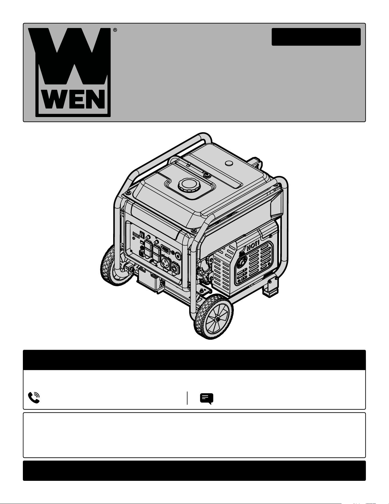
Thanks for purchasing the WEN 8750-Watt Dual Fuel Inverter Generator. Refer to the illustration below for the loca-
tion of the serial number on the specifications label. Record the generator information in the spaces provided below.
If assistance for information or service is required, please contact customer service by calling 1-847-429-9263, M-F
8-5 CST; you will be asked to provide the following generator information when calling.
Generator Model Number: DF875iX
Date of Purchase: _______________________________________________
Purchased From: ________________________________________________
Serial Number: _________________________________________________
TO MAXIMIZE THE LIFESPAN OF YOUR GENERATOR: We recommend running your generator at least once a
month for 20 to 30 minutes. Start the generator according to the instructions and plug a small load in to make
sure the outlet is producing electricity.
SERVICE RECORD
Record the service dates of your generator in the chart below. Please perform maintenance checks and operations
according to the “Maintenance” section of the manual.
Service Record Date Date Date Date Date Date
Change Oil
Change Spark Plug
Clean Fuel Tank
Clean Air Cleaner
Clean Spark Arrestor
4
Serial Number

5
GENERAL SAFETY RULES
WORK AREA SAFETY
1. Keep work area clean and well lit. Cluttered or dark
areas invite accidents.
2. Do not operate power tools in explosive atmo-
spheres, such as in the presence of flammable liquids,
gases or dust. Power tools create sparks which may ig-
nite the dust or fumes.
3. Keep children and bystanders away while operating
a power tool. Distractions can cause you to lose control.
ELECTRICAL SAFETY
1. Power tool plugs must match the outlet. Never mod-
ify the plug in any way. Do not use any adapter plugs
with earthed (grounded) power tools. Unmodified plugs
and matching outlets will reduce risk of electric shock.
2. Avoid body contact with earthed or grounded surfac-
es such as pipes, radiators, ranges and refrigerators.
There is an increased risk of electric shock if your body
is earthed or grounded.
3. Do not expose power tools to rain or wet conditions.
Water entering a power tool will increase the risk of elec-
tric shock.
4. Do not abuse the cord. Never use the cord for car-
rying, pulling or unplugging the power tool. Keep cord
away from heat, oil, sharp edges or moving parts.
Damaged or entangled cords increase the risk of electric
shock.
5. When operating a power tool outdoors, use an ex-
tension cord suitable for outdoor use. Use of a cord
suitable for outdoor use reduces the risk of electric
shock.
6. If operating a power tool in a damp location is un-
avoidable, use a ground fault circuit interrupter (GFCI)
protected supply. Use of a GFCI reduces the risk of elec-
tric shock.
PERSONAL SAFETY
1. Stay alert, watch what you are doing and use com-
mon sense when operating a power tool. Do not use a
power tool while you are tired or under the influence
of drugs, alcohol or medication. A moment of inatten-
tion while operating power tools may result in serious
personal injury.
2. Use personal protective equipment. Always wear
eye protection. Protective equipment such as a respira-
tory mask, non-skid safety shoes and hearing protection
used for appropriate conditions will reduce the risk of
personal injury.
3. Prevent unintentional starting. Ensure the switch is
in the off-position before connecting to power source
and/or battery pack, picking up or carrying the tool.
Carrying power tools with your finger on the switch or
energizing power tools that have the switch on invites
accidents.
4. Remove any adjusting key or wrench before turning
the power tool on. A wrench or a key left attached to a
rotating part of the power tool may result in personal
injury.
5. Do not overreach. Keep proper footing and balance
at all times. This enables better control of the power
tool in unexpected situations.
6. Dress properly. Do not wear loose clothing or jew-
elry. Keep your hair and clothing away from moving
parts. Loose clothes, jewelry or long hair can be caught
in moving parts.
Safety is a combination of common sense, staying alert and knowing how your item works. The term “power tool”
in the warnings refers to your mains-operated (corded) power tool or battery-operated (cordless) power tool.
SAVE THESE SAFETY INSTRUCTIONS.
WARNING! Read all safety warnings and all instructions. Failure to follow the warnings and instructions may
result in electric shock, fire and/or serious injury.

6
GENERAL SAFETY RULES
7. If devices are provided for the connection of dust
extraction and collection facilities, ensure these are
connected and properly used. Use of dust collection
can reduce dust-related hazards.
POWER TOOL USE AND CARE
1. Do not force the power tool. Use the correct power
tool for your application. The correct power tool will
do the job better and safer at the rate for which it was
designed.
2. Do not use the power tool if the switch does not turn
it on and off. Any power tool that cannot be controlled
with the switch is dangerous and must be repaired.
3. Disconnect the plug from the power source and/or
the battery pack from the power tool before making
any adjustments, changing accessories, or storing
power tools. Such preventive safety measures reduce
the risk of starting the power tool accidentally.
4. Store idle power tools out of the reach of children
and do not allow persons unfamiliar with the power
tool or these instructions to operate the power tool.
Power tools are dangerous in the hands of untrained us-
ers.
5. Maintain power tools. Check for misalignment or
binding of moving parts, breakage of parts and any
other condition that may affect the power tool’s opera-
tion. If damaged, have the power tool repaired before
use. Many accidents are caused by poorly maintained
power tools.
6. Keep cutting tools sharp and clean. Properly main-
tained cutting tools with sharp cutting edges are less
likely to bind and are easier to control.
7. Use the power tool, accessories and tool bits, etc.
in accordance with these instructions, taking into ac-
count the working conditions and the work to be per-
formed. Use of the power tool for operations different
from those intended could result in a hazardous situa-
tion.
8. Use clamps to secure your workpiece to a stable
surface. Holding a workpiece by hand or using your
body to support it may lead to loss of control.
9. KEEP GUARDS IN PLACE and in working order.
SERVICE
1. Have your power tool serviced by a qualified repair
person using only identical replacement parts. This
will ensure that the safety of the power tool is main-
tained.
CALIFORNIA PROPOSITION 65 WARNING
Some dust created by power sanding, sawing, grinding,
drilling, and other construction activities may contain
chemicals, including lead, known to the State of Califor-
nia to cause cancer, birth defects, or other reproductive
harm. Wash hands after handling. Some examples of
these chemicals are:
• Lead from lead-based paints.
• Crystalline silica from bricks, cement, and other
masonry products.
• Arsenic and chromium from chemically treated
lumber.
Your risk from these exposures varies depending on
how often you do this type of work. To reduce your ex-
posure to these chemicals, work in a well-ventilated area
with approved safety equipment such as dust masks
specially designed to filter out microscopic particles.
Safety is a combination of common sense, staying alert and knowing how your item works. The term “power tool”
in the warnings refers to your mains-operated (corded) power tool or battery-operated (cordless) power tool.
SAVE THESE SAFETY INSTRUCTIONS.
WARNING! Read all safety warnings and all instructions. Failure to follow the warnings and instructions may
result in electric shock, fire and/or serious injury.
7
GENERATOR SAFETY WARNINGS
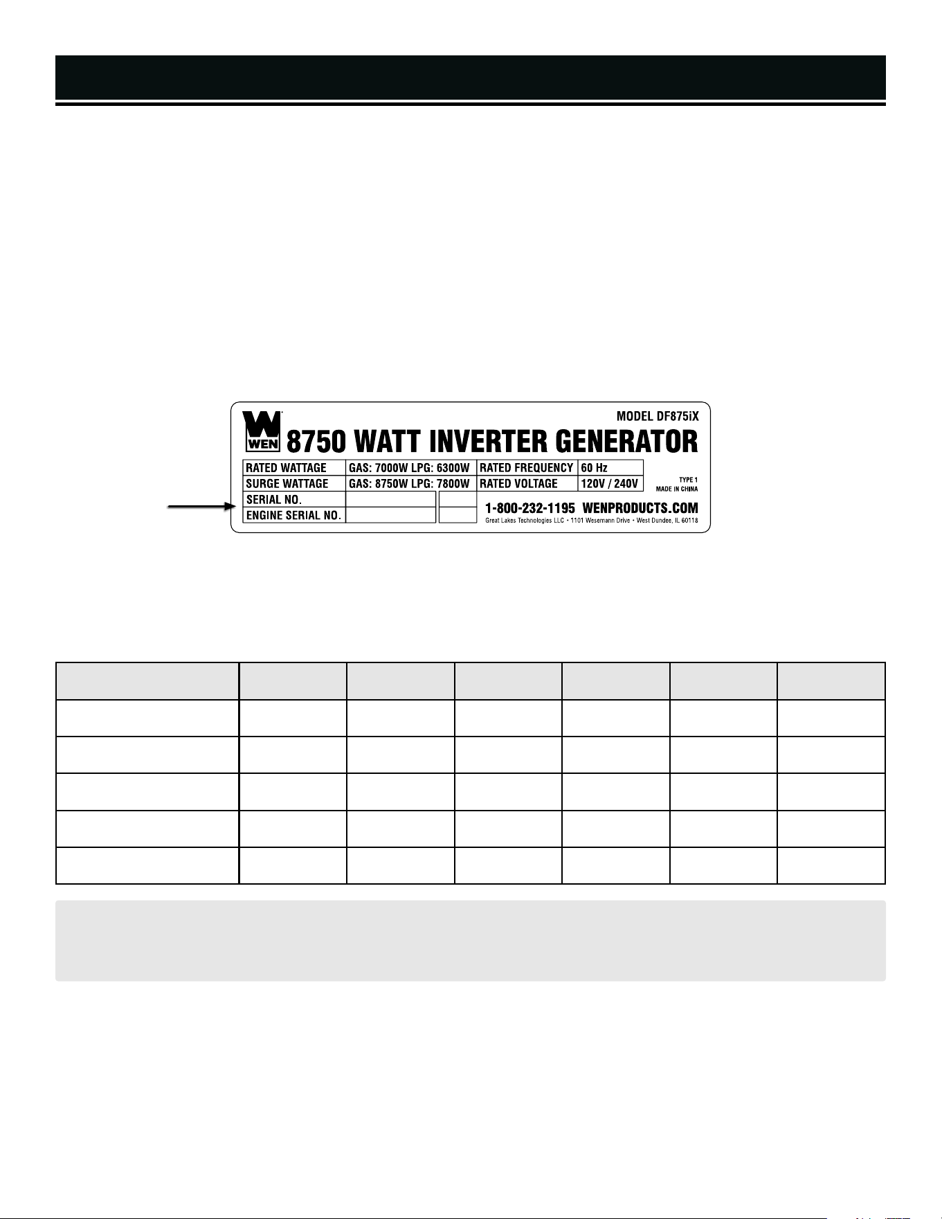
DANGER! CARBON MONOXIDE
Using a generator indoors CAN KILL YOU IN MINUTES. Generator exhaust contains carbon monoxide (CO). This
is a poison gas you cannot see or smell. If you can smell the generator exhaust, you are breathing CO. But even
if you cannot smell the exhaust, you could be breathing CO.
NEVER use a generator inside homes, garages, crawl spaces, or other partially enclosed areas. Deadly levels
of carbon monoxide can build up in these areas. Using a fan or opening windows and doors does NOT supply
enough fresh air. ONLY use a generator outside and far away from windows, doors, and vents. These openings
can pull in generator exhaust.
Even if you use a generator correctly, CO may leak into the home. ALWAYS use a battery-powered or battery-
backup CO alarm in the home. If you start to feel sick, dizzy, or weak after the generator has been running, move
to fresh air RIGHT AWAY. See a doctor. You may have carbon monoxide poisoning.
WARNING! RISK OF EXPLOSION. HIGHLY FLAMMABLE: This generator may emit highly flammable and
explosive gasoline vapors, which can cause severe burns or even death, if ignited. A nearby open flame can lead
to explosion even if not directly in contact with gasoline.
• Do not operate near open flame, heat, or any other ignition source. Do not smoke near the generator.
• Always operate on a firm, level surface.
• Always turn generator off before refueling. Allow generator to cool for at least 2 minutes before removing
fuel cap. Loosen cap slowly to relieve pressure in tank.
• Do not overfill fuel tank. Gasoline may expand during operation. Do not fill to the top of the tank. Allow for
expansion. Always check for spilled fuel before operating.
• If fuel spills, move the generator at least 30 feet away from the spill and wipe clean any spilled fuel before
starting the engine.
• Empty fuel tank before storing or transporting the generator.
WARNING! If this generator is used as a supply for a building’s wiring system, the generator must be in-
stalled by a qualified electrician and connected to a transfer switch as a separately derived system in accordance
with all applicable laws and electrical codes and the National Electrical Code, NFPA 70. The generator shall be
connected to a transfer switch that switches all conductors excluding the equipment grounding conductor. The
frame of the generator shall be connected to an approved grounding electrode.
CALIFORNIA PROPOSITION 65 WARNING: This product contains chemicals and produces exhaust known
to the State of California to cause cancer, birth defects and other reproductive harm. For more information, visit
www.P65Warnings.ca.gov

8
OPERATING ENVIRONMENT
1. Using a generator indoors can kill you in minutes.
Only use a generator outside and far away from win-
dows, doors and vents.
2. Do not smoke near the generator.
3. Do not operate near open flame, heat, or flammable
materials. This generator may emit highly flammable
and explosive gasoline vapors, which can cause severe
burns or even death if ignited. A nearby open flame can
lead to an explosion even if it isn’t directly in contact with
gasoline.
4. Do not expose the generator to rainy or wet con-
ditions; doing so significantly increases the risk of
electrical shock. Never handle the generator, electronic
devices, or any cord while standing in water, while bare-
foot, or when hands or feet are wet.
5. Always operate the generator on a dry, firm, level
surface.
6. The generator should have at least 5 feet of clear-
ance from buildings or other equipment during opera-
tion.
7. Do not allow children or non-qualified persons to
operate the generator.
GENERATOR PREPARATION
1. Always ground the generator before using it to maxi-
mize safety (see “Ground the Generator” section).
2. Do not overfill fuel tank, as gasoline may expand
during operation. Do not fill to the very top of the tank.
Leave room for gasoline expansion. Always check for
spilled fuel before operating.
3. If any part of the generator, electrical device or pow-
er cord is broken, damaged, or defective, make sure
it is repaired or replaced before operation. Service
should only be performed by a qualified technician. Do
not use receptacles or cords that show signs of damage,
such as broken or cracked insulation.
4. Use a ground fault circuit interrupter (GFCI) in highly
conductive areas such as metal decking or steel work.
Extension cords with in-line GFCIs are recommended for
these operations to maximize safety.
5. If connecting the generator to a building’s electri-
cal system for standby power, you MUST consult a
qualified electrician and install a transfer switch. Such
connections must comply with local electrical laws and
codes. Failure to comply can create a back-feed, which
may result in serious injury or death to utility workers.
6. Never modify the generator in any way. Modifying
or using the machine for any other purpose for which it
is not designed may result in serious injuries, machine
damage and voiding of the warranty.
GENERATOR OPERATION
1. Only use the generator for its intended purposes.
Modifying or using the generator for operations for
which it was not designed may cause hazards and per-
sonal injury.
2. Do not touch bare wires or receptacles (outlets).
3. Do not exceed the wattage capacity of the generator
by plugging in more electrical devices than the unit
can handle. This could damage the generator and/or
connected electrical devices. Check the operating volt-
age and frequency requirements of all electrical devices
prior to plugging them into the generator.
WARNING! Do not let comfort or familiarity with the product replace strict adherence to product safety rules.
Failure to follow the safety instructions may result in serious personal injury.
GENERATOR SAFETY WARNINGS
TO MAXIMIZE THE LIFESPAN OF YOUR GENERATOR: We recommend running your generator at least once a
month for 20 to 30 minutes. Start the generator according to the instructions and plug a small load in to make
sure the outlet is producing electricity. If you do not run it often, it will greatly shorten the generator’s lifespan
and void the warranty.

9
GENERATOR SAFETY WARNINGS
4. Allow generator to run for several minutes before
connecting electrical devices. Do not start or stop en-
gine with electrical devices plugged in to the receptacles.
Failure to do so could damage the generator and/or con-
nected electrical devices.
5. Do not turn on electrical devices until after they are
connected to the generator.
6. Generators vibrate in normal use. During and after
the use of the generator, inspect both the generator as
well as extension and power supply cords for damage
resulting from vibration.
7. Do not touch hot parts. This generator produces heat
when running. Temperatures near exhaust can exceed
150ºF (65ºC). Allow generator to cool down after use be-
fore touching engine or areas of the generator that be-
come hot during use.
8. Turn off all connected electrical devices before stop-
ping the generator.
9. Always turn generator off before refueling.
Allow generator to cool for at least 2 minutes before re-
moving fuel cap. Loosen cap slowly to relieve pressure
in tank.
10. Turn the engine switch to “STOP” position when
the engine is not running.
11. Empty fuel tank before storing or transporting the
generator. Do not store generator or gasoline near fur-
naces, water heaters, or any other appliances that pro-
duce heat or have automatic ignitions. Store the genera-
tor and fuel away from sparks, open flames, pilot lights,
heat and other sources of ignition.
12. Always wash hands after handling generator.
CAUTION: Misuse of this generator can damage it or
shorten its lifespan.
UNPACKING
With the help of a friend or trustworthy foe, such as one of your in-laws, carefully remove the generator from the
packaging and place it on a sturdy, flat surface. Make sure to take out all contents and accessories. Do not discard
the packaging until everything is removed. Check the packing list below to make sure you have all of the parts and
accessories. If any part is missing or broken, please contact customer service at 1-847-429-9263 (M-F 8-5 CST),
or email [email protected].
UNPACKING & PACKING LIST
Spark Plug Socket .......................................1
Screwdriver .................................................1
Wrenches ....................................................4
(19/17mm (2), 10/13mm, 8/10mm)
Generator ....................................................1
Handle .........................................................1
Funnel .........................................................1
User Manual ................................................1
DF875iX-HA36 High Altitude Kit ..................1
DF875iX-HA68 High Altitude Kit ..................1
Box 1 of 2
Wheels .....................................2
LPG Regulator ..........................1
Hardware Bag (Box 2 of 2)
Wheel Assembly
Wheel Axle and Nut ..................2
Handle Assembly
Handle Bracket .........................1
M6x30 Bolt ..............................4
R-Clip and Handle Pin ..............1
Feet Assembly
Feet ..........................................2
M6x40 Bolt ..............................4
M6 Nut .....................................4
Tools & Accessories (Box 2 of 2)
Box 2 of 2
10
Fuel Cap
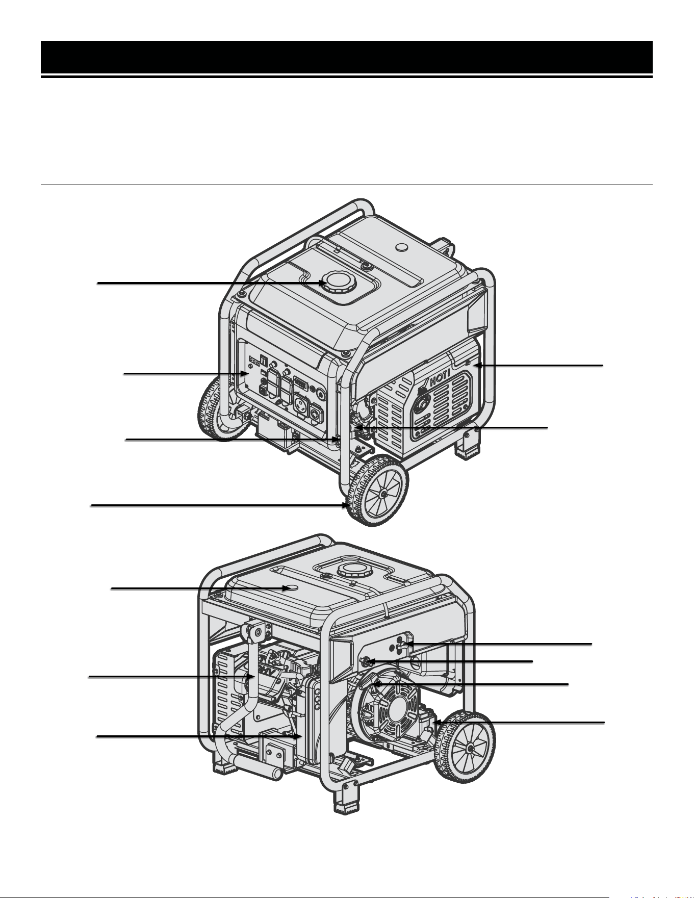
KNOW YOUR GENERATOR
TOOL PURPOSE
Generators provide you with power when and where you need it most. Refer to the following diagrams to become
familiarized with all the parts and controls of your Generator. The components will be referred to later in the manual
for assembly and operation instructions.
GENERATOR
Control Panel
Air Filter
Oil Drain Plug
Wheels
Handle
LPG Inlet
Recoil Starter
Fuel Gauge
Muffler
Oil Fill & Dipstick
Battery
Fuel Selector Switch
11
KNOW YOUR GENERATOR
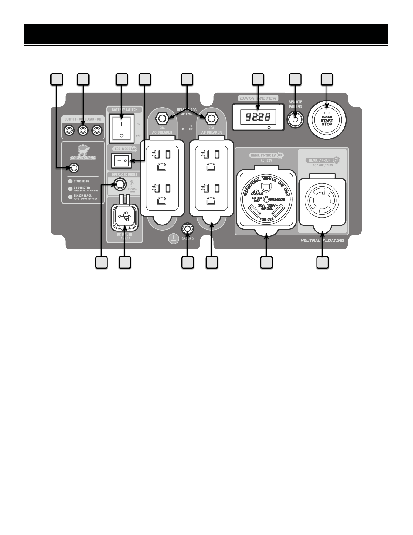
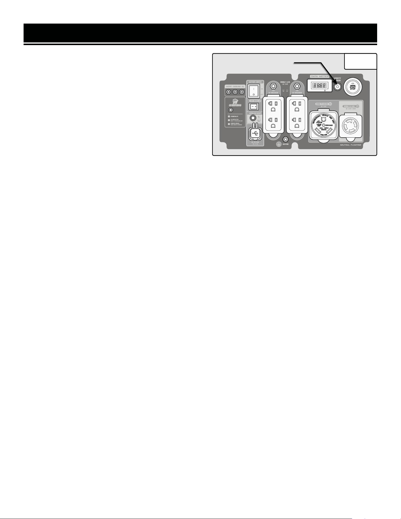
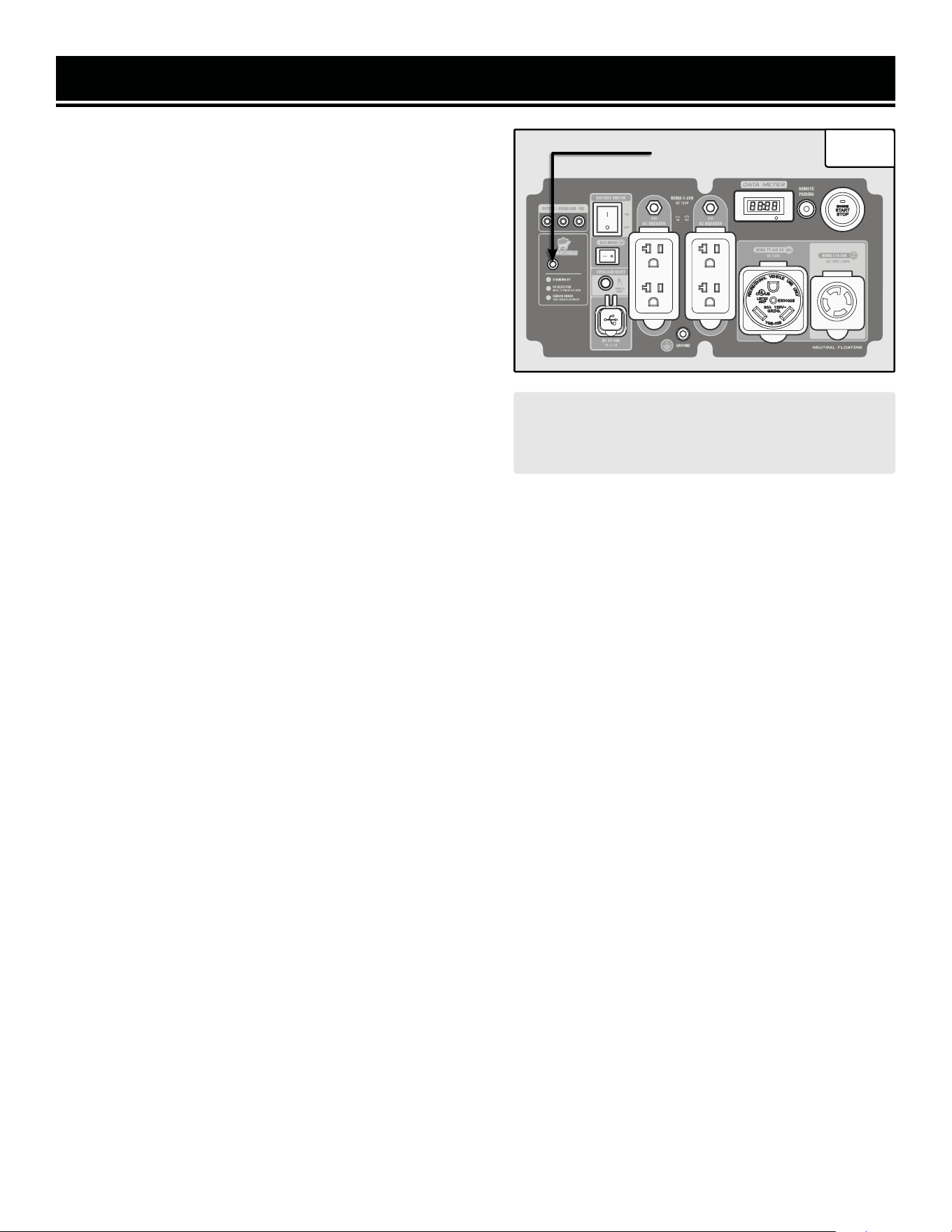
CONTROL PANEL
1 2 4 5 8
9
1. CO WATCHDOG Carbon Monoxide Monitor
Measures the accumulation of poisonous CO gas while the gen-
erator is running. If the level of CO gas gets too high, the CO
Watchdog system will automatically shut down the generator.
See p. 31 for more information.
2. Indicator Lights
Output light (green) will turn on when receptacles have power,
overload light (red) will turn on if the generator is overloaded, the
oil light (yellow) will turn on if the oil is low.
3. Battery Switch
Control whether or not the battery is connected to the control
panel. Always turn the battery switch OFF to conserve power af-
ter shutting down the generator. You can also shut down the
generator by turning the battery switch OFF.
4. Eco-Mode Switch
Flip this switch to ON to increase fuel economy and runtime
when the load is below 75% of the rated load (5250W gasoline,
4725W LPG).
5. Circuit Breakers
Push the button to reset the circuit.
6. Data Meter
Displays voltage, frequency, total runtime (HHHH), and session
runtime (HH:MM). Press the MODE button to switch between
displays.
7. Remote Pairing Button
Use this button to pair the remote and generator. See “Re-
mote Start” section (pages 23 - 24) for more information.
8. Engine Start / Stop Button
Use this button to start or stop the generator. The button
will also flash different colors to provide important infor-
mation about your generator. See “Starting the Generator”
(page 21) and “Shutting Off the Generator” (page 32) sec-
tions for more information.
9. NEMA L14-30R
AC 120V/240V split-phase.
10. AC 120V NEMA TT-30R
Standard RV connector.
11. AC 120V NEMA 5-20R Duplex Receptacles
20A standard household outlets.
12. Grounding Nut
13. DC 5V USB Ports
The upper USB port provides 2.1A, while the lower port
provides 1A of power.
14. Overload Reset Button
If the overload light is ON, press this button to reset.
3
13
76
10111214
12
ASSEMBLY & ADJUSTMENTS
HIGH ALTITUDE OPERATION ABOVE 3000 FEET
The fuel system on this generator may be affected by opera-
tion at high altitudes. Proper operation can be ensured by
installing an altitude kit at altitudes higher than 3000 feet
above sea level. At elevations above 8000 feet, the engine
may experience a decrease in performance, even with the
proper altitude kit. Operating this generator without the high
altitude kit at elevations above 3000 feet may increase the
engine’s emissions and decrease both fuel economy and
performance.
NOTE: If you plan to only use propane at high altitudes, a
high-altitude kit is not required. High-altitude kits are only
required if you plan to use gasoline at high altitudes.
INSTALLING THE HIGH ALTITUDE KIT
This kit should be installed by a qualified mechanic. Con-
tact customer service at 1-847-429-9263 (M-F 8-5 CST),
or email [email protected] for information
about service centers near you. Two high-altitude kits (part
numbers DF875iX-HA36 and DF875iX-HA68) are included
with your generator.
Gather the parts in the high altitude kit.
1. Flip the engine switch to the STOP position.
2. Turn the fuel valve to the OFF position.
3. Prepare an approved gasoline-storage container to catch
any spilled fuel. Place it near the fuel valve.
4. The carburetor can be accessed from the backside of the
generator between the engine and the air filter. Loosen the
screws (Fig. 1) on the bottom of the carburetor with a Phil-
lipshead screwdriver (not included). CAUTION! The carbu-
retor bowl may have gas in it which will leak upon loosen-
ing the screws and removing the solenoid.
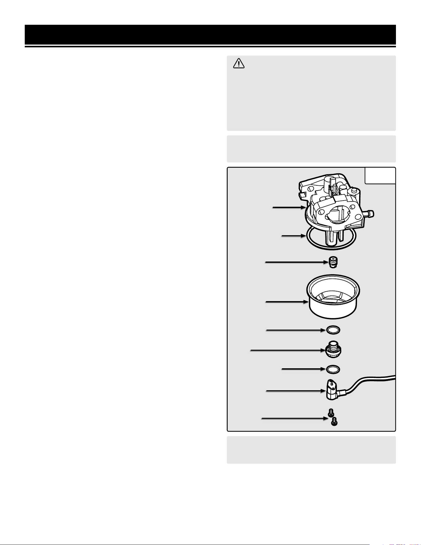
5. Remove the screws, solenoid, solenoid seal, bolt, bolt
seal, fuel cup, fuel cup seal, and main jet from the body of
the carburetor assembly (Fig. 1).
6. Replace the main jet with the replacement jet needed for
your altitude range (3000-6000 ft or 6000-8000 ft). NOTE:
The fuel cup seal, bolt seal and solenoid seal may be
damaged during removal and should be replaced with the
new ones from the kit.
WARNING! To prevent serious injury from
fire, follow the kit installation procedures in a
well-ventilated area away from ignition sources.
If the engine is hot from use, shut the engine off
and wait for it to cool before proceeding. Do not
smoke near the generator. Warranty will be void
if adjustments are not made for high altitude use.
CAUTION! UNINSTALL the high altitude kit when
operating at altitudes below 3000 feet.
CAUTION! UNINSTALL the high altitude kit when
operating at altitudes below 3000 feet.
7. Reassemble the fuel cup seal, fuel cup, bolt seal, bolt, solenoid seal, solenoid and screws. Tighten with a Phillips-
head screwdriver to secure.
8. Wipe up any spilled fuel and allow excess to evaporate before starting the engine. WARNING! To prevent fire,
do not start the engine while the smell of fuel hangs in the air.
CarburetorCarburetor
AssemblyAssembly
Fuel Cup SealFuel Cup Seal
Fuel CupFuel Cup
Main JetMain Jet
Bolt SealBolt Seal
BoltBolt
Fig. 1
Solenoid SealSolenoid Seal
SolenoidSolenoid
ScrewsScrews

13
ASSEMBLY & ADJUSTMENTS
WARNING! Do not turn on the generator until it is fully assembled according to the instructions. Read
through and become familiarized with the following procedures of handling and adjusting your tool.
Failure to follow the safety instructions may result in serious personal injury.
• Never use the handle as a lifting point to support the entire weight of the generator. Only use the handle
to pull the generator with the help of the wheels.
• Use caution when collapsing the handle. Hands and fingers could get caught and pinched.
ASSEMBLY
Refer to the packing list to gather the proper parts and tools for installing the feet, wheels, and handles.
NOTE: There are different sizes of bolts/nuts; be sure to use the proper bolts/nuts for each assembly step.
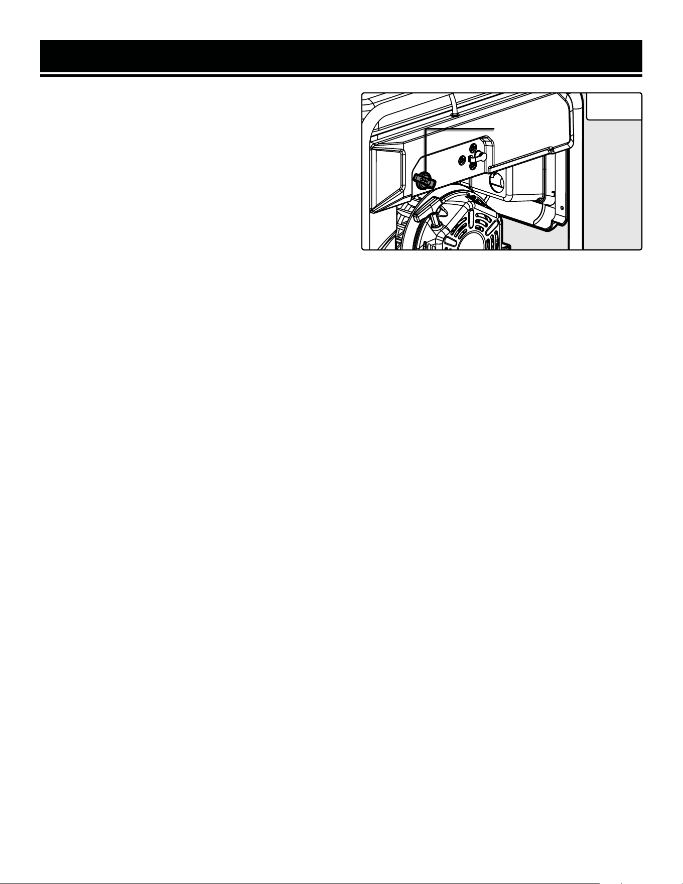
REMOVING THE SHIPPING BRACKETS
1. Your generator comes with two red shipping brackets installed to help prevent shipping damage. Failure to re-
move these brackets can damage the engine. Make sure to remove these brackets BEFORE adding oil or gasoline.
2. Gently tip the generator onto its side. Use the included wrenches (or a socket set) to remove the nuts and bolts
that hold the shipping brackets to the bottom of the engine crankcase.
3. Once the shipping brackets are removed, they may be recycled. You will not need them.
INSTALLING THE FEET
The feet are installed on the muffler and air filter sides of the generator.
1. Prepare a set of blocks on level ground (a 4×4 block of wood works well). Place the generator on the blocks. Have
someone help you lift the generator.
2. Slide one foot into place on the generator frame and align the holes on the foot with the holes on the frame.
3. Slide the M6x40 bolts through the legs and generator frame. Tighten the M6 nuts onto the bolts using a wrench.
4. Repeat on the opposite side.
INSTALLING THE WHEELS
1. Remove the nuts from the axles.
2. Insert the thick side of the axle through the generator frame. Install and tighten the nut.
3. Slide the wheel onto the thin side of the axle. Install and tighten the nut.
NOTE: You can use a wrench on the hex shank of the axle to hold it steady when tightening the nuts.
INSTALLING THE HANDLE
1. Install the bracket on the top of the generator frame using the four M6x30 bolts. Tighten using a wrench.
2. Insert the handle pin through the bracket and handle. Secure it using the R-clip.
NOTE: Refer to the instructions on the following pages before starting your generator.
14
GENERATOR PREPARATION
The following section describes the necessary steps to prepare the generator for use. If you are unsure about how to
perform any of the steps please call 1-847-429-9263 (M-F 8-5 CST) for customer service. Failure to perform these
steps properly can damage the generator or shorten its life.
STEP 1 - ADD/CHECK OIL
The generator is shipped without oil. User must add the proper amount of oil before operating the generator for the
first time. The oil capacity of the engine crankcase is 37.2 fl oz (1.1 L).
CAUTION! Keep the generator level. Tilting the generator
to assist in filling will cause oil to flow into the wrong
areas of the engine and cause damage.
TO ADD OIL:
1. Place the generator on a level surface. Make sure the en-
gine is OFF before adding or checking oil.
2. Unscrew the oil dipstick (Fig. 3) from the engine.
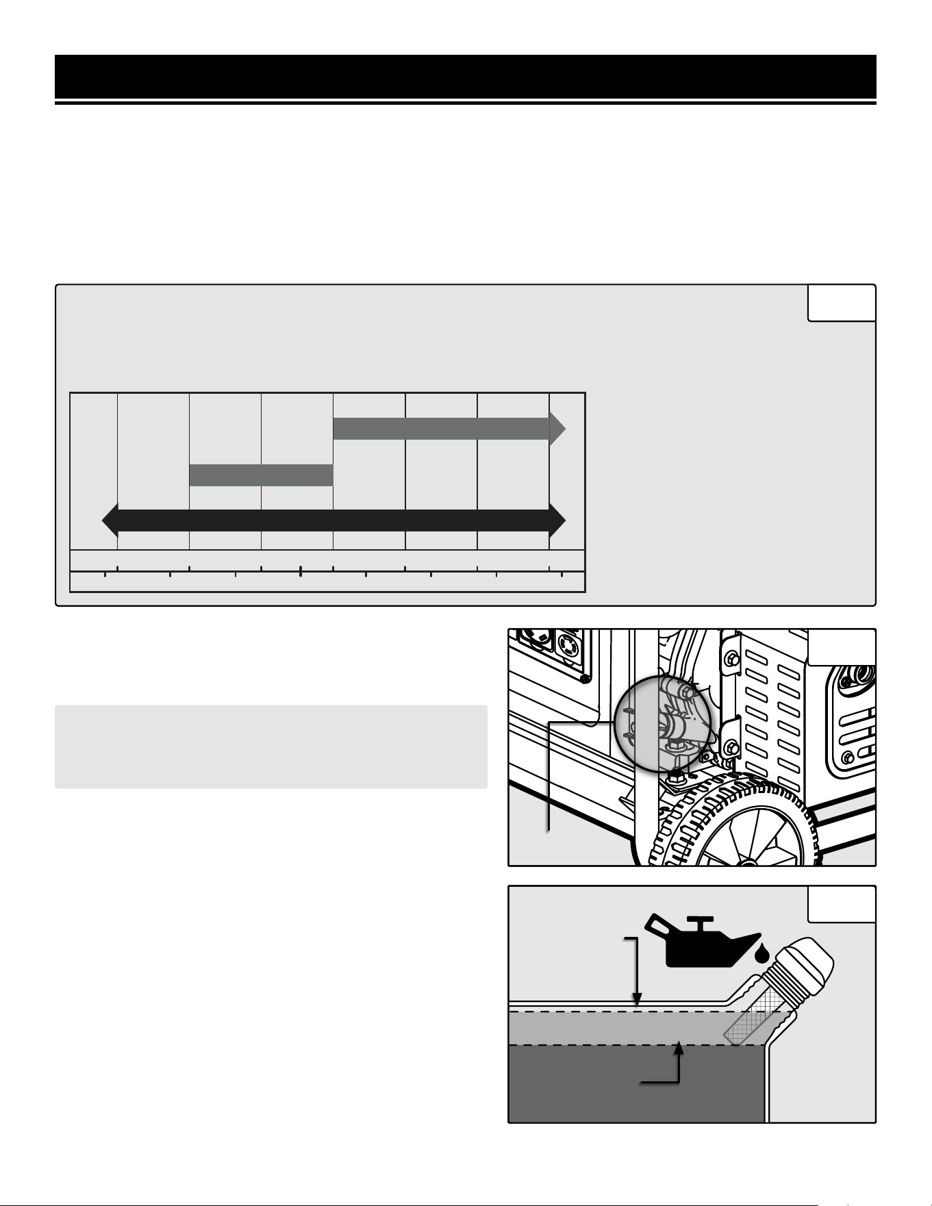
3. Using an oil funnel or appropriate dispenser, slowly add
oil into the oil fill, being careful not to overfill the unit. Fill the
crankcase to the upper fill line so you can visually see the oil
coming halfway up the oil fill threads. See Fig. 4.
4. Reinstall the oil dipstick and firmly tighten it. Wipe clean
any spilled oil.
CAUTION! For subsequent operation, the oil level should be
checked before each use, or after every 8 hours of operation.
The generator is equipped with a low-oil sensor and will not
start without a sufficient amount of oil. Follow the instruc-
tions on the next page to check the oil level.
• 30W Engine Oil
Temperatures above 40°F
• 10W-30 Engine Oil
Temperatures between 0°F - 40°F
• Synthetic 5W-30 Engine Oil
All temperature ranges
ENGINE OIL RECOMMENDATIONS
Select good quality detergent oil bearing the American Petroleum Institute (API) service classifications
SJ, SL, or SM (synthetic oils may be used). Select the SAE viscosity grade of oil that matches the ex-
pected operating temperature.
°F
°C
-20 0 20 32 40 60 80 100
40200
-20
-10
10
-30 30
Upper Fill Line
Lower Fill Line
Dipstick
Fig. 2
Fig. 3
Fig. 4
30W
10W-30
Synthetic 5W-30
15
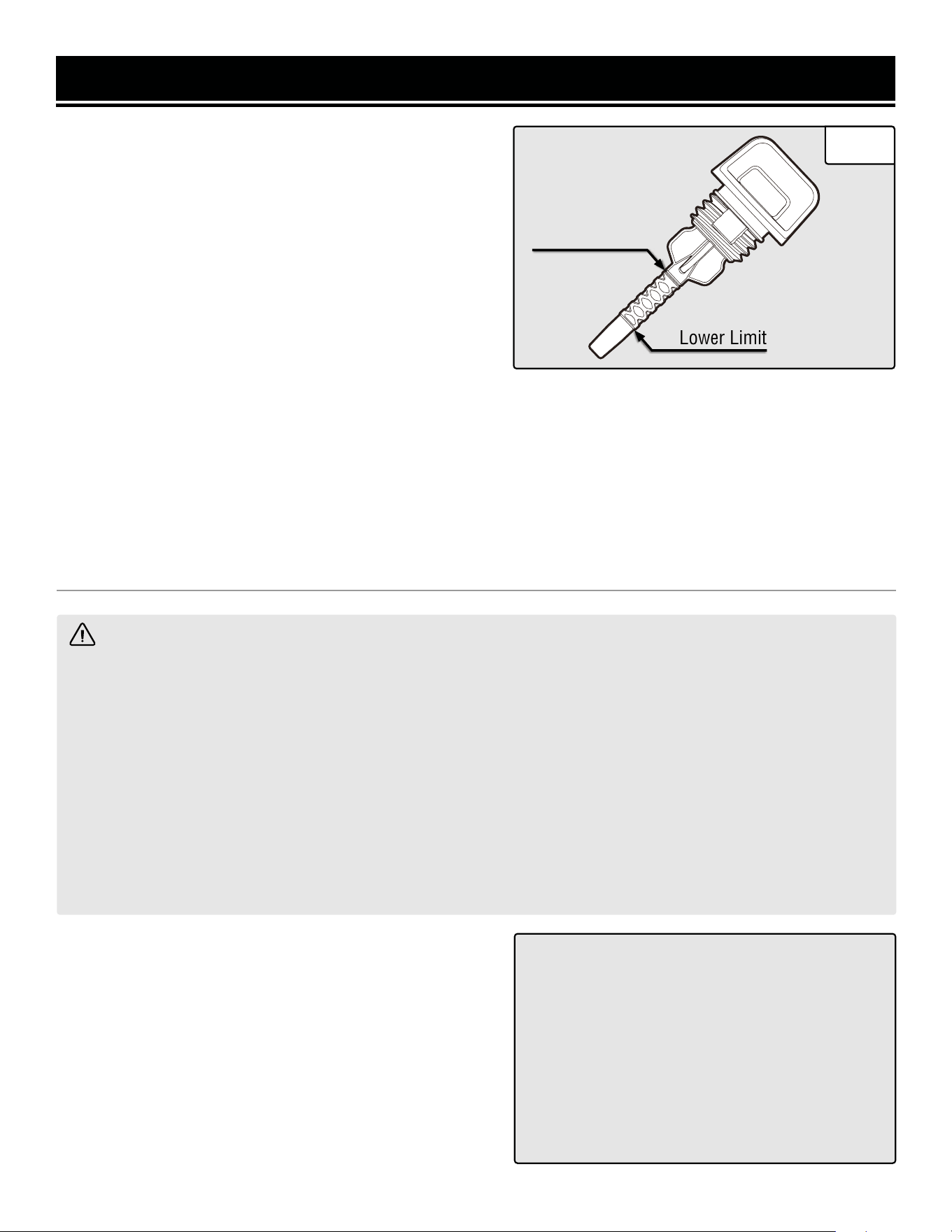
Lower Limit
Upper Limit
TO CHECK OIL LEVEL (before every subsequent start):
1. Place the generator on a level surface. Make sure the
engine is OFF before adding or checking oil.
2. Remove and wipe the dipstick with a clean rag.
3. Insert the dipstick into the oil fill without screwing it in.
Remove the dipstick to check the oil mark.
4. If the oil mark covers less than one half of the dipstick,
slowly add oil until the oil mark reaches the top of the dip-
stick (or when you can see the oil coming halfway up the
oil fill threads). See Fig. 5.
WARNING: RISK OF EXPLOSION. HIGHLY FLAMMABLE: This generator may emit highly flammable and
explosive gasoline vapors, which can cause severe burns or even death, if ignited. A nearby open flame can lead
to explosion even if not directly in contact with gasoline.
• Do not operate near open flame, heat, or any other ignition source. Do not smoke near the generator.
• Always operate on a firm, level surface.
• Always turn generator off before refueling. Allow generator to cool for at least 2 minutes before removing
fuel cap. Loosen cap slowly to relieve pressure in tank.
• Do not overfill fuel tank. Gasoline may expand during operation. Do not fill to the top of the tank. Allow for
expansion. Always check for spilled fuel before operating.
• If fuel spills, move the generator at least 30 feet away from the spill and wipe clean any spilled fuel before
starting the engine.
• Empty fuel tank before storing or transporting the generator.
ONLY use fresh (within 30 days from purchase), lead-free
gasoline with a minimum of 87 octane rating. The genera-
tor performs best with ethanol-free gasoline. DO NOT use
gasoline with over 10% ethanol.
The capacity of the fuel tank is 4.2 US gallons (16.0L). Do
not mix oil with gasoline.
Follow the instructions on the next page to add gasoline.
IMPORTANT:
• Avoid getting dirt or water into the fuel tank.
• Keep gasoline away from sparks, open flames,
pilot lights, heat, and other sources of ignition.
• Gasoline can age in the tank and make starting
difficult. Never store the generator for more
than 2 months with fuel in the tank.
• Never use an oil/gasoline mixture.
• Never use old gasoline.
OIL LEVEL SHUTDOWN
To protect the unit from damage, the generator is equipped with a low-oil-pressure shutoff that will automatically
shut down the engine when the oil level is too low. The oil level of the engine should be checked before each start
to ensure that the engine crankcase contains sufficient lubricant.
STEP 2 - ADD/CHECK FUEL
GENERATOR PREPARATION
Fig. 5
FUEL OPTION A: GASOLINE
TO ADD GASOLINE:
1. Place the generator on a level surface. Make sure the
engine is OFF before adding or checking the fuel.
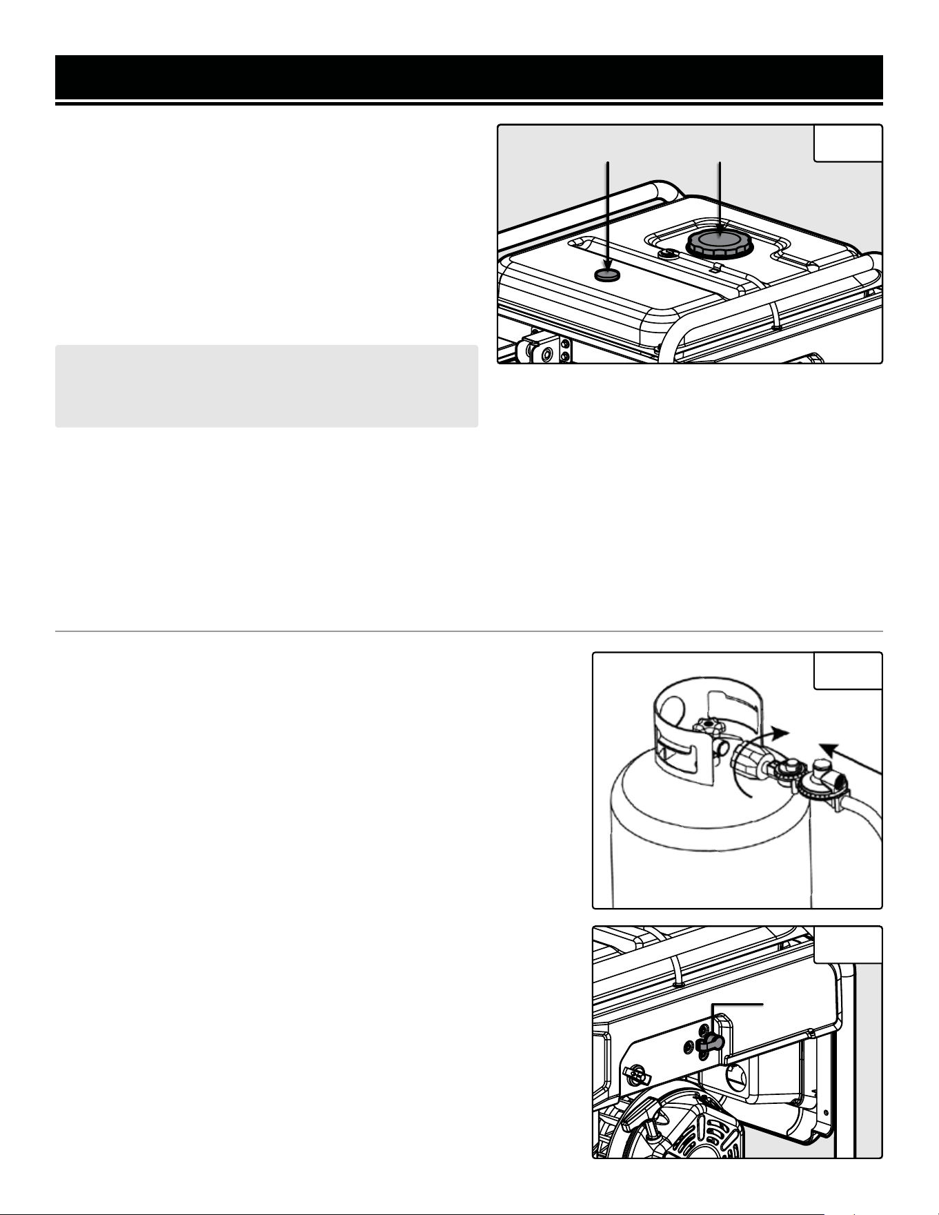
2. Unscrew the fuel cap (Fig. 6) and set it aside. The fuel
cap may be tight and hard to unscrew.
3. Slowly add unleaded gasoline to the fuel tank. Be careful
not to overfill. Reinstall fuel cap and wipe clean any spilled
gasoline with a dry cloth.
NOTE: Do not fill the fuel tank to the very top. If you do
so, gasoline will expand and spill during use, even with
the fuel cap in place.
TO CHECK GAS LEVEL (before every subsequent start):
1. Before starting the generator, check the fuel gauge (Fig. 6) to see if there is sufficient fuel inside the tank:
• E = Empty
• F = Full
2. If the tank is empty add gasoline to the gas tank. See above section, "To Add Gasoline".
GENERATOR PREPARATION
Fig. 6
Fuel Cap
FUEL OPTION B: LIQUID PETROLEUM GAS (LPG)
To connect your generator to an LPG cylinder:
1. Take off the safety caps from the cylinder valve, generator mounted
regulator, and regulator connecting hose ends.
2. With the LPG tank valve closed, attach the LPG regulator connecting
hose to the valve. Turn the plastic coupling from the hose right (clock-
wise) to tighten hose assembly onto the LPG tank (Fig. 7).
3. Remove the protective rubber cover from the LPG inlet (Fig. 8 - 1)
on the side of the generator. Connect the nut on the other end of the
regulator connecting hose to the LPG inlet. Tighten the nut using the
included 19mm wrench.
1
Fig. 7
Fig. 8
16
Fuel Gauge
ABOUT THE BATTERY
1. The lithium-ion battery supplied with your generator is only partially charged, in order to maximize its service
life. The battery may not have enough charge to start the engine during its first use. If this is the case, connect the
battery according to the instructions below, and start the generator using the recoil starter, according to the instruc-
tions below. The battery will receive charge when the generator is running.
2. Lithium-ion batteries are subject to a natural aging process. The battery must be replaced at the latest when its
capacity falls to just 80% of its capacity when new. Weakened cells in an aged battery are no longer capable of meet-
ing the high power requirements needed for the proper operation of your generator, and therefore pose a safety risk.
3. DO NOT INCINERATE BATTERY. Do not throw the battery into an open fire as this poses a risk of explosion. Do
not ignite the battery or expose it to fire.
STEP 3 - CONNECT THE BATTERY
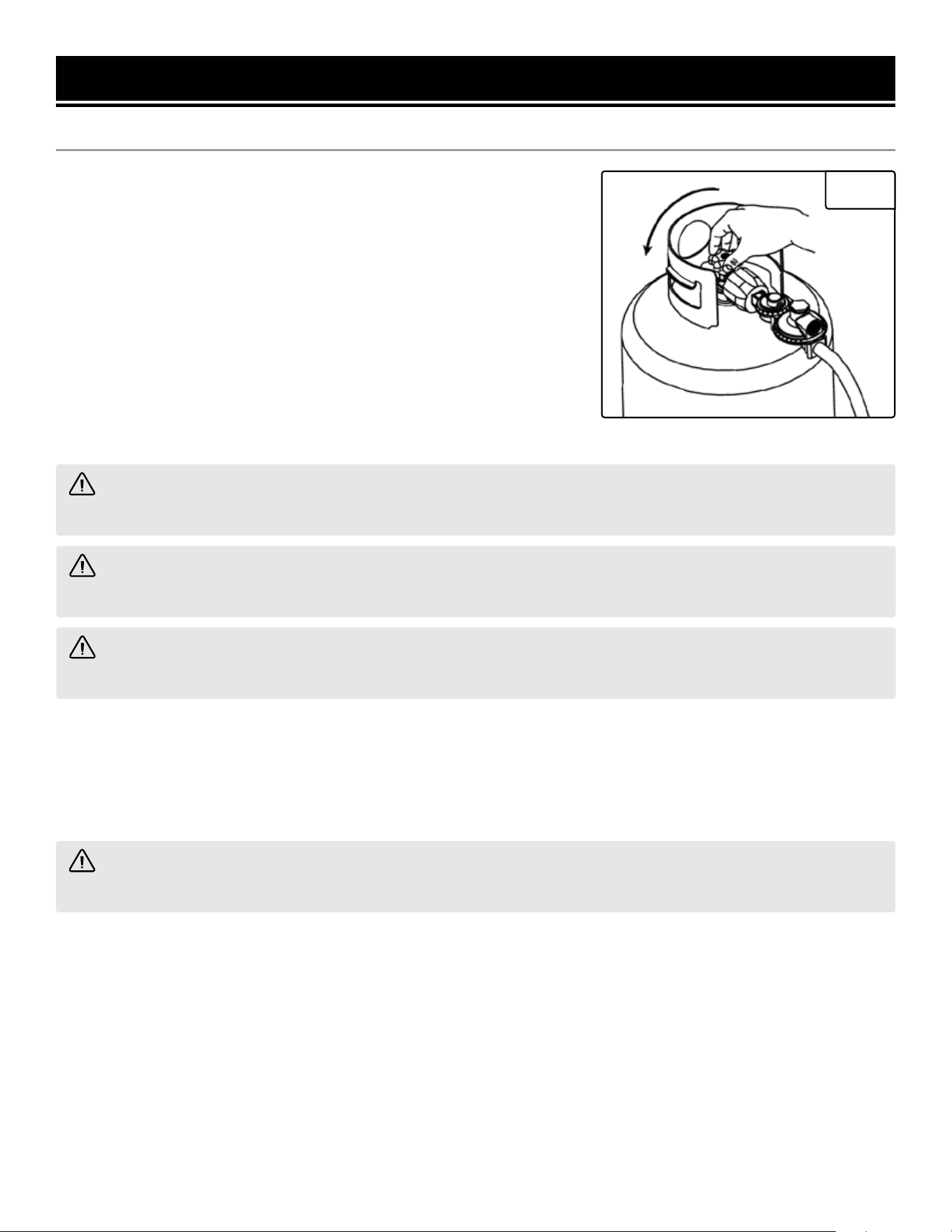
CAUTION! Always position the LPG cylinder so the connection between the tank and LPG inlet won’t cause
sharp bends or kinks in the hose.
GENERATOR PREPARATION
FUEL OPTION B: LIQUID PETROLEUM GAS (LPG) (CONT.)
4. Turn the LPG tank valve ON (Fig. 9) and check for leaks by spraying
soapy water to check connections. If bubbles appear, become larger
in size, or increase in number, a leak exists. This MUST be corrected
before using generator. Contact WEN customer service at 1-847-429-
9263, M-F 8-5 CST, or email [email protected] for as-
sistance.
NOTE: You can use Teflon (or other tape) to secure the connection of
the LPG hose to your generator.
NOTE: If you would like to purchase other accessories for your dual-
fuel generator, consult your local dealer of propane and propane ac-
cessories, I tell you what.
WARNING! Risk of burns. Contact with liquid contents of cylinder will cause freeze burns to the skin. If liquid
contents contacts skin or eyes, seek immediate medical attention.
WARNING! When transporting and storing, keep cylinder secured in an upright position with cylinder valve
turned off. Keep cylinders ventilated and away from heat when in a vehicle.
Fig. 9
WARNING! Use only genuine WEN batteries with your generator (part no. 56380i-1304). Use of other bat-
teries may induce premature product failure and could pose a safety risk.
NOTE: Make sure the generator can handle the load(s) you plan to connect. The generator can provide more power
when running on gasoline than on LPG. Consult the specifications table on p. 3, as well as the “Calculating the Watt-
age of Your Device(s)” chart to ensure that your load(s) will not exceed the rated wattage for a particular fuel. See
also "Switching Fuels" section for more information.
17
NOTE: Grounding wire and grounding rods are not
included with the generator. A generally acceptable
grounding wire is a No. 12 AWG (American Wire
Gauge) stranded copper wire. Grounding codes
can vary by location. Contact a local electrician to
check the area codes.
ABOUT THE BATTERY (CONT.)
4. AVOID DAMAGE AND SHOCKS. Immediately replace batteries that have been dropped from a height of more than
one meter (3 feet) or those that have been exposed to violent shocks, even if the housing of the battery appears to
be undamaged. The battery cells inside the battery may have suffered serious damage. In such instances, please
read the waste disposal information on p. 31 for proper battery disposal.
5. DO NOT CRUSH, DROP OR DAMAGE BATTERY. Do not use the battery if it has sustained a sharp blow, been
dropped, run over or has been damaged in any way (e.g. pierced with a nail, hit with a hammer, stepped on, etc.).
6. DO NOT DISASSEMBLE. Incorrect reassembly may pose a serious risk of electric shock, fire or exposure to toxic
battery chemicals. If the battery or charger are damaged, call WEN customer service at 1-847-429-9263 for as-
sistance.
7. DO NOT SHORT CIRCUIT. Batteries will short circuit if a metal object makes a connection between the positive
and negative contacts on the battery. Do not place the battery near anything that may cause a short circuit, such as
paper clips, coins, keys, screws, nails and other metallic objects. A short-circuited battery poses a risk of fire and
severe personal injury.
NOTE: The safe temperature range for charging the battery is 25°F – 104°F. The generator is shipped with the lith-
ium-ion battery’s negative (-) terminal disconnected to maximize safety. To start the generator using electric start,
the battery must be connected.
GENERATOR PREPARATION
To connect the battery:
1. Remove the black battery bracket by removing the two
bolts that hold the battery bracket in place. Pull out the bat-
tery for easier access.
2. Pull back the protective cover from the red (+) lead near
the battery.
3. Attach the red (+) lead to the positive (+) terminal on the
battery, using the nut and bolt.
4. Repeat for the black (-) battery lead. Secure it to the
negative (-) terminal on the battery.
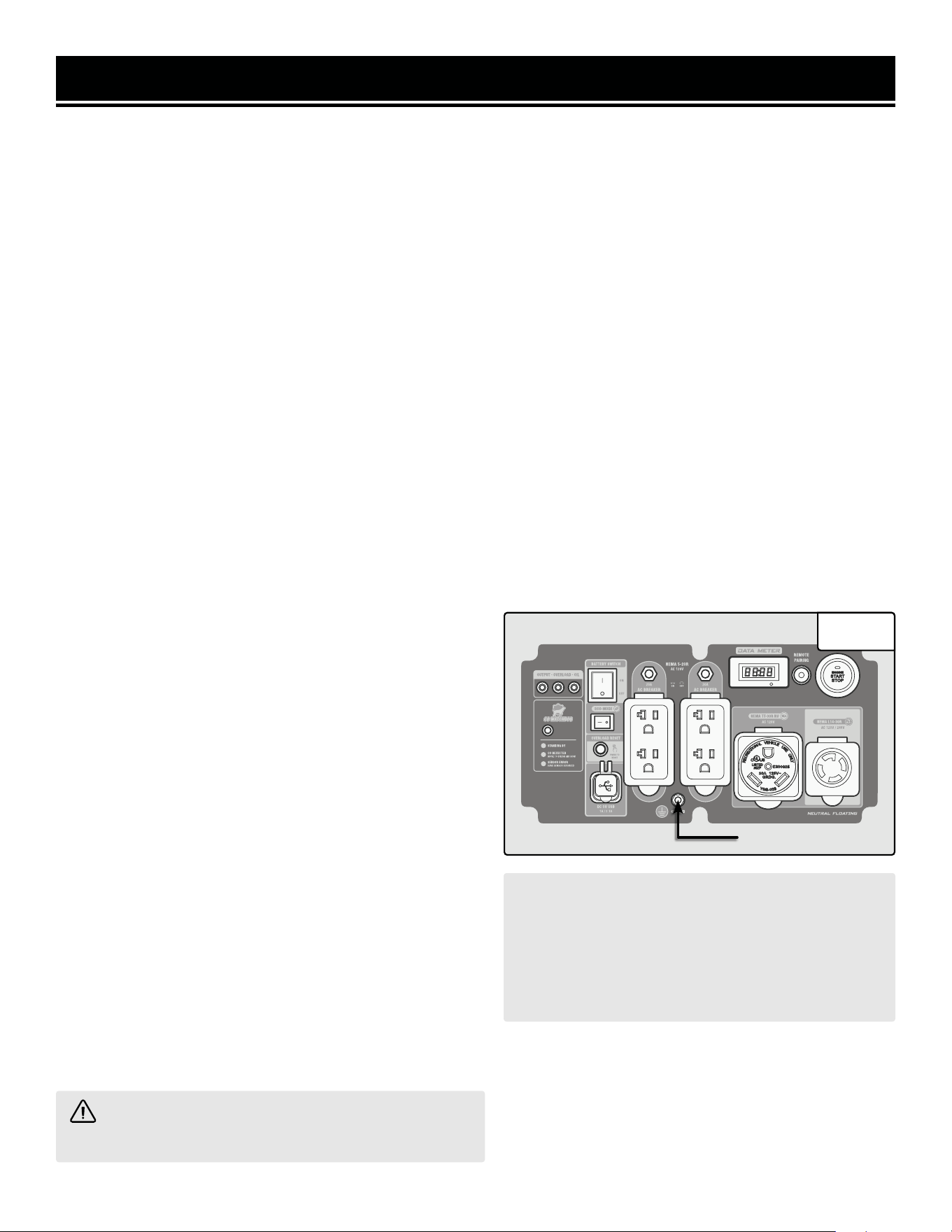
STEP 4 - GROUNDING THE GENERATOR
To reduce the risk of electric shock and to maximize safety,
the generator should be properly grounded.
1. Attach one end of the grounding wire to the grounding
nut (Fig. 10). Tighten the nut to secure the grounding wire.
2. Connect the other end of the grounding wire to a copper,
brass, or steel-grounding rod that is driven into the earth.
WARNING! Failure to properly ground the generator
increases your risk of electric shock.
Grounding Nut
Fig. 10
18
STARTING THE GENERATOR
CAUTION! Disconnect all electrical loads from the generator before attempting to start it.
Before starting the generator, make sure you have read and performed the steps in the “Generator Preparation” sec-
tion of this manual. If you are unsure about how to perform any of the steps in this manual please call
1-847-429-9263 (M-F 8-5 CST) for customer service.
To maximize safety, ALWAYS ground the generator before using it. Refer to "Step 3 - Ground The Generator."
Use a ground fault circuit interrupter (GFCI) in highly conductive areas such as metal decking or steel work. GFCIs
are available in-line with some extension cords.
DANGER: CARBON MONOXIDE
Using a generator indoors CAN KILL YOU IN MINUTES. Generator exhaust contains carbon monoxide (CO). This
is a poison gas you cannot see or smell. If you can smell the generator exhaust, you are breathing CO. But even
if you cannot smell the exhaust, you could be breathing CO.
NEVER use a generator inside homes, garages, crawl spaces, or other partially enclosed areas. Deadly levels
of carbon monoxide can build up in these areas. Using a fan or opening windows and doors does NOT supply
enough fresh air. ONLY use a generator outside and far away from windows, doors, and vents. These openings
can pull in generator exhaust.
Even if you use a generator correctly, CO may leak into the home. ALWAYS use a battery-powered or battery-
backup CO alarm in the home. If you start to feel sick, dizzy, or weak after the generator has been running, move
to fresh air RIGHT AWAY. See a doctor. You may have carbon monoxide poisoning.
WARNING: The exhaust from this product contains chemicals known to the State of California to cause
cancer, birth defects, or other reproductive harm.
WARNING: Do not operate generator near open flame or flammable materials This generator may emit
highly flammable and explosive gasoline vapors, which can cause severe burns or even death if ignited. A
nearby open flame can lead to explosion even if it isn’t directly in contact with gasoline. Do not smoke near the
generator.
WARNING: This generator produces powerful voltage, which can result in electrocution.
WARNING: Do not use in rainy or wet conditions. Do not touch bare wires or receptacles (outlets). Do not
allow children or non-qualified persons to operate.
WARNING: Generator should only be connected to electrical devices, either directly or with an extension
cord. NEVER connect to a building electrical system unless a qualified electrician has connected the generator to
a transfer switch as a separately derived system. Such connections must comply with local electrical laws and
codes. Failure to comply can create a back-feed, which may result in serious injury or death to utility workers.
Follow the instructions on the next page to start your generator.
19
STARTING THE GENERATOR
BEFORE STARTING THE GENERATOR
1. Verify that the generator is outside on a dry, level sur-
face. Allow at least two feet of clearance on all sides of the
generator.
2. To maximize safety, check that the generator is properly
grounded. Refer to "Step 4 - Ground The Generator."
3. Check that there is a sufficient level of oil in the crank-
case. Add oil if necessary. Refer to "Step 1 - Add/Check
Oil."
4. If using gasoline, make sure there is enough gasoline
in the fuel tank. Add fuel if necessary (see "Add / check
Fuel"). If using LPG, make sure there is enough propane in
the tank, and that the tank and regulator hose are properly
connected.
5. Make sure all electrical devices are unplugged from the
generator during ignition. Otherwise it will be difficult for
the engine to start.
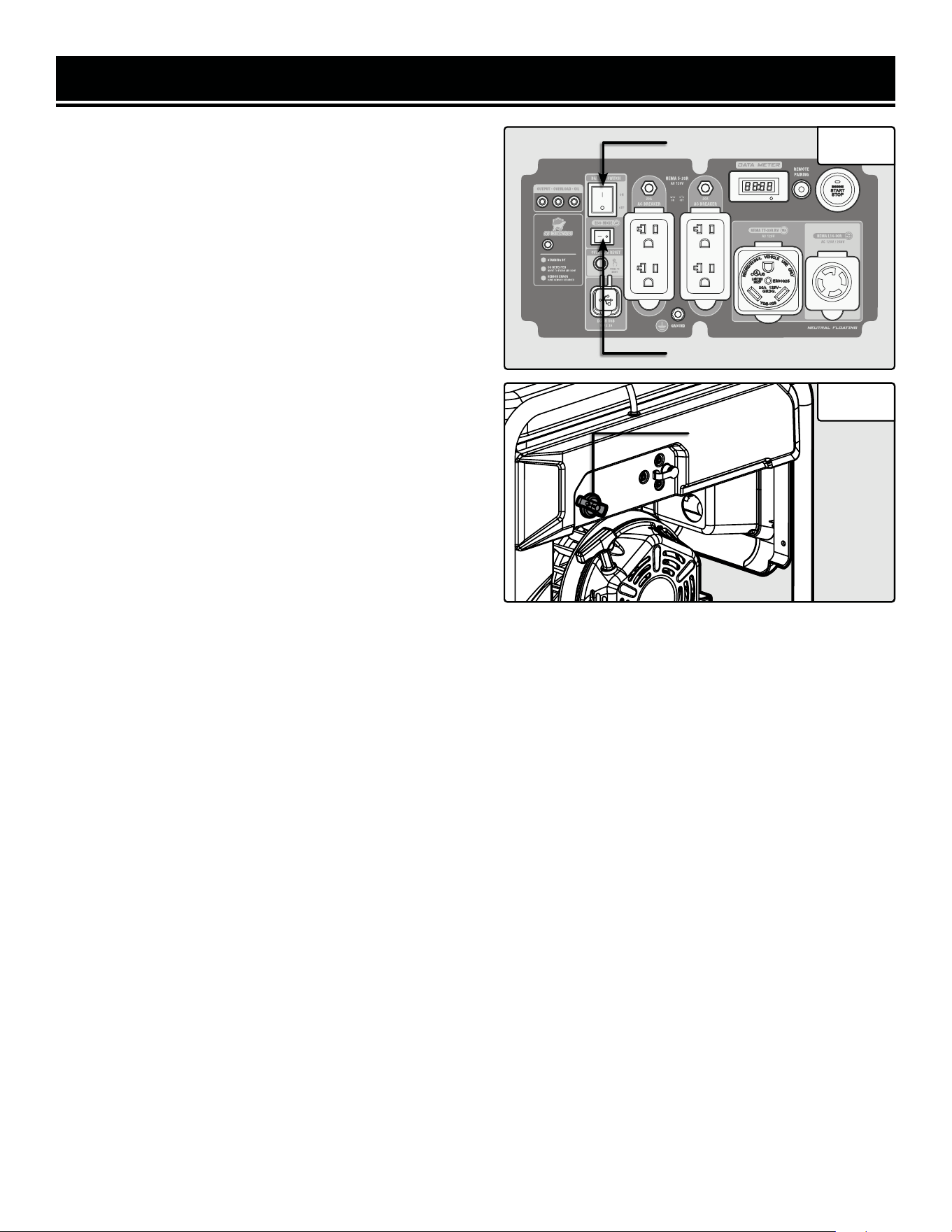
STARTING THE GENERATOR (GASOLINE)
1.Turn the ECO-mode switch (Fig. 11 - 1) to OFF during
starting.
Fig. 11
2.Turn the battery switch (Fig. 11 - 2) to ON during starting.
3.Ensure that all electrical devices are disconnected from the generator.
4.Turn the fuel selector switch (Fig. 12 - 1) to the “GASOLINE” position (right).
Fig. 12
2
1
1
20
STARTING THE GENERATOR
STARTING THE GENERATOR (GASOLINE) CONT.
a. To start the engine using the electric starter:
i. Make sure the battery is properly connected. If the
battery is dead or not connected, the generator will
not start.
ii. Press the engine start/stop button (Fig. 13 - 1)
once. Do not hold it down.
iii.. The engine start/stop button will begin flashing
green, and will automatically adjust the choke and
start the engine.
iv. The generator will make 6 attempts to start the
engine.
NOTE: If after 6 attempts the engine has not started,
the engine start/stop button will flash red for 30 sec-
onds. Check the troubleshooting steps on p. 40. If
after checking all these steps the engine still will not
start, contact WEN customer service for assistance.
b. To start the engine using the recoil starter:
i. Move the choke lever (Fig. 14 - 1) left to the closed
position. If the engine is warm, move the choke lever
right to the open position.
ii. Pull the recoil starter handle (Fig. 14 - 2) slowly
until a slight resistance is felt, then pull quickly to
start the engine. Return cord gently into the recoil
starter. Never allow the cord to snap back.
NOTE: If the engine does not start after multiple at-
tempts, please consult the troubleshooting guide on
p. 40 before attempting to start the generator again. If
problems persist, please contact WEN customer ser-
vice (see front page of manual).
iii. Slowly move the choke lever right to the open po-
sition.
Fig. 13
Fig. 14
1
2
21
1
STARTING THE GENERATOR
a. To start the engine using the electric starter:
i. Make sure the battery is properly connected. If the bat-
tery is dead or not connected, the generator will not start.
ii. Press the engine start/stop button (Fig. 13 - 1) once. Do
not hold it down.
iii.. The engine start/stop button will begin flashing green,
and will automatically adjust the choke and start the en-
gine.
iv. The generator will make 6 attempts to start the engine.
NOTE: If after 6 attempts the engine has not started, the
engine start/stop button will flash red for 30 seconds.
Check the troubleshooting steps on p. 40. If after checking
all these steps the engine still will not start, contact WEN
customer service for assistance.
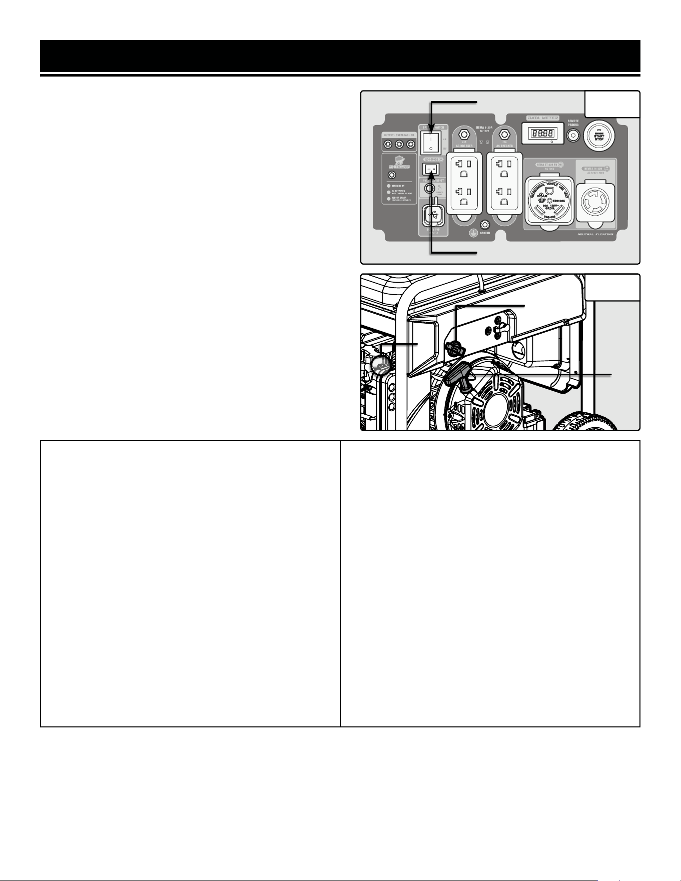
b. To start the engine using the recoil starter:
i. Move the choke lever (Fig. 16 - 2) left to the closed posi-
tion. If the engine is warm, move the choke lever right to
the open position.
ii. Pull the recoil starter handle (Fig. 16 - 1) slowly until a
slight resistance is felt, then pull quickly to start the en-
gine. Return cord gently into the recoil starter. Never allow
the cord to snap back.
NOTE: If the engine does not start after multiple attempts,
please consult the troubleshooting guide on p. 40 before
attempting to start the generator again. If problems per-
sist, please contact WEN customer service (see front page
of manual).
iii. Slowly move the choke lever right to the open position.
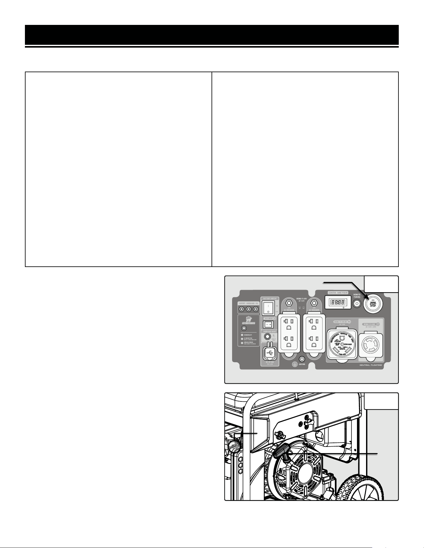
STARTING THE GENERATOR (PROPANE)
1. Turn the ECO-mode switch (Fig. 15 - 1) to OFF during
starting.
2. Turn the battery switch (Fig. 15 - 2) to ON during start-
ing.
3. Ensure that all electrical devices are disconnected from
the generator.
4. Turn the fuel selector switch (Fig. 16 - 1) to the “PRO-
PANE” position (left).
5. Make sure the propane regulator and hose are securely
attached to the propane cylinder and the propane inlet
on the generator, and that the propane cylinder valve is
turned ON.
6. Prime the engine. To do this, close the choke lever (Fig.
16 - 2) and pull the recoil starter (Fig. 16 - 3) 1 – 3 times.
Fig. 15
Fig. 16
2
1
1
3
7. After the engine has started, the engine start/stop button will continue flashing green for a few moments, then will
stay solid green while the generator is running. The output indicator light (green) will light up, and the multi-meter
will turn on.
8. Allow the generator to run for several minutes before attempting to connect any electrical devices. This allows the
generator to stabilize its speed and temperature.
22
2

STARTING THE GENERATOR
USING THE REMOTE-START FUNCTION
Your generator comes with a remote-start function, enabling you to (what else?) start your generator remotely. Your
generator and the included remote have been paired at the factory, and you can use the remote immediately.
NOTE: In order for the remote start function to work properly, you must be within 164 ft (50 m) of the generator.
The remote’s effective range may vary depending on the battery's state of charge, as well as miscellaneous environ-
mental factors, radio interference, etc.
STARTING THE GENERATOR (REMOTE START)
1. Ensure that the battery switch (Fig. 15 - 2) on the panel is turned to ON. Ensure that the battery is connected and
is not dead. Ensure that there is enough fuel, and the fuel selector switch is turned to the proper fuel source.
2. Ensure that all electrical devices are disconnected from the generator. Ensure that ECO-MODE (Fig. 15 - 1) is OFF.
3. Press the ON button on the remote control once. DO NOT hold the button down. The generator will wait for a
moment, then automatically adjust the choke and start.
NOTE: The generator will make 6 attempts to start the engine automatically. If after 6 attempts the engine has not
started, the engine start/stop button will flash red for 30 seconds. Check the troubleshooting steps on p. 40. If after
checking all these steps the engine still will not start, contact WEN customer service for assistance.
4. Connect electrical devices.
NOTE: After the CO Watchdog system shuts down the generator, the generator cannot be restarted using remote
start, for safety reasons. You must manually restart the generator using the recoil or electric starter. After doing this,
the remote start can be used normally. See p. 31 for more information.
STOPPING THE GENERATOR (REMOTE START)
1. Turn off all electrical devices prior to unplugging them from the generator. Unplugging running devices can cause
damage to the generator. Never start or stop the generator with electrical devices plugged in or turned on.
2. Let engine run at no-load for several minutes to stabilize its internal temperature. Ensure that ECO-mode is OFF.
3. Press the OFF button on the remote control once. Do NOT hold the button down. The generator will then shut
down. The engine start/stop button will flash red and green simultaneously a few times to indicate that the generator
was shut down remotely.
4. Once the engine shuts down, if the battery switch is still set to ON, the generator will enter standby mode. In
standby mode, the generator can be started using the remote. The engine start/stop button will blink green once
every 2 seconds to remind you that the generator is in standby mode.
NOTE: There is no limit to how long the generator will stay in standby mode, so if you forget to turn off the battery
switch, it is possible that the battery will be drained the next time you try to use the generator. If you see the engine
start/stop switch flashing green, always make sure the battery switch is turned OFF.
NOTE: During remote start and remote start, you may see the data meter display flicker slightly. This is normal and
does not indicate a problem.
NOTE: If you purchase a new remote, you will need to pair the new remote with the generator. Follow instructions
below. When replacing batteries in a remote, you should not need to pair the generator and remote again, but if you
find that it does not work with new batteries, follow the instructions below to pair the generator and remote again.
23
STARTING THE GENERATOR
STORING THE REMOTE
We recommend clasping your remote to the loops on the
USB cover on the panel for easy access.
PAIRING THE REMOTE AND GENERATOR
1. Make sure the battery is connected and charged, and the
battery switch on the panel is set to ON.
2. Press the remote pairing button (Fig. 17 - 1) on the con-
trol panel once.
3. The engine start/stop button will flash red once.
Fig. 17
1
4. Press the ON and OFF buttons on the remote simultaneously, within 5 seconds after seeing the engine start/stop
button flash.
5. The engine start/stop button will flash red 4 times.
6. The generator will enter standby mode, and the engine start/stop button will flash green every 2 seconds.
NOTE: If in step 4, the ON and OFF buttons are not pressed within 5 seconds, the generator will enter its standby
state. Start again from step 2 to pair the remote and generator.
UNPAIRING THE REMOTE AND GENERATOR
1. Make sure the battery is connected and charged, and the battery switch on the panel is set to ON.
2. Press the remote pairing button on the control panel 5 times quickly (within 5 seconds).
3. The engine start/stop button will flash red 4 times, and will clear all stored remote control data.
4. The generator will enter standby mode, and the engine start/stop button will flash green every 2 seconds.
REPLACING REMOTE BATTERIES
Your generator’s remote comes with a CR2032 battery pre-installed and ready to use. However, the battery will
eventually die and need to be replaced.
1. Use a fine-tipped Phillips-head screwdriver to remove the 3 screws on the back of the remote. Do not drop or lose
the screws. Open the back of the remote and remove the CR2032 battery from the battery compartment.
2. Install a new CR2032 battery in the same orientation as you removed the old battery. (The + side, which should
say "CR2032", faces the back of the remote.)
3. Replace the back of the remote and tighten the screws. Follow the instructions above to pair your remote with the
generator (if necessary).
24

STARTING THE GENERATOR
STANDBY MODE
Once the generator is shut down, the generator’s remote control function will stay in standby mode while the battery
switch is ON. In standby mode, the generator can be started using the remote. The engine start/stop button will blink
green once every 2 seconds to remind you that the generator is in standby mode.
NOTE: There is no limit to how long the generator will stay in standby mode, so if you forget to turn off the battery
switch, it is possible that the battery will be drained the next time you try to use the generator. If you see the engine
start/stop switch flashing green, always make sure the battery switch is turned OFF.
PAIRING MULTIPLE REMOTES
You can pair up to 15 remotes at a time with your generator. Remotes (part no. DF875iX-1432) can be purchased
from wenproducts.com. To pair a new remote with your generator, follow instructions above in “Pairing the Remote
and the Generator”. You can also pair one remote with as many generators as you like.
NOTE: If you have multiple remotes paired with your generator and you unpair one remote, you will also unpair
the other remotes simultaneously. You will need to pair the other remotes with the generator again before they can
be used. If at any point you have questions, problems, or concerns about the remote start function, consult the
Troubleshooting guide or contact customer service at 1-847-429-9263.
25
CALCULATING THE WATTAGE OF YOUR DEVICE(S)
Connect electrical devices running on AC current according to their wattage requirements. Calculate the total run-
ning wattage and starting wattage of the device(s) you wish to connect, and MAKE SURE that they are within the
capacity of your generator and the capacity of each individual outlet.
Generator
Wattage
Capacity
GENERATOR RUNNING (RATED) WATTS GENERATOR STARTING (SURGE) WATTS
GAS: 7000W LPG: 6300W GAS: 8750W LPG: 7800W
What this means:
The generator can produce a maximum of
7000W (gas) or 6300W (LPG) on a continu-
ous basis to supply ongoing power to your
electronic devices.
NOTE: Also check the rated amperage for
each outlet and make sure not to overload
the individual outlets.
What this means:
Some devices such as box fans require short
bursts of extra power in addition to the rated
wattage listed by the device to start their mo
-
tors.
The generator can produce a maximum wattage
of 8750W (gas) or 7800W (LPG) for a short pe
-
riod of time (seconds) to cover the extra start-
ing power required by your electronic devices.
Electronic
Device
Wattage
Calculation
Find the wattage information of each device you plan to connect. The information should
be listed on the device or in its instruction manual, or you may refer to Table 2 - Estimated
Wattages of Common Electrical Appliances.
The wattage can be calculated using this equation: Watts = Volts x Amperes
To calculate the total running watts of your de-
vices:
+ Add up the running wattages of all the device(s)
you plan to connect.
= The total running (rated) wattage.
This wattage should NOT exceed the running
wattage of 7000W (gas) or 6300W (LPG).
It is recommended to maintain a load at or be-
low 6300W (gas) or 5670W (LPG) (90% of the
rated output) to ensure steady voltage output
and to prolong the generator’s lifespan.
To calculate the total starting watts of your
devices:
+ Add up the total running wattage of all the
device(s) you plan to connect.
+ Add the single highest ADDITIONAL start-
ing wattage out of the device(s) you plan to
connect.
= The total starting (surge) wattage.
This wattage should NOT exceed the starting
wattage of
8750W (gas) or 7800W (LPG).
If any of either of the total calculated running watts or starting watts is higher than the capac-
ity of your generator, adjust the load until both wattage requirements are met. Otherwise you
will overload the generator, and cause damage to the engine and your electrical device(s).
Table 1 - How to Calculate Wattages
USING THE GENERATOR
26

CALCULATING THE WATTAGE OF YOUR DEVICE(S) - CONTINUED
The chart below serves as a reference for the estimated wattage requirements of common electrical devices. How-
ever, do not solely rely on this chart - all electronics and appliances are built differently. Always check the wattage
listed on the electrical device before consulting this chart.
Tool or Appliance Rated (Running) Watts Surge (Starting) Watts
Hot Plate 2500 0
Saw - Radial Arm 2000 2000
Electric Stove (Each Element) 1500-2800 0
Saw - Circular 1500 1500
Air Compressor (1 HP) 1500 3000
Window Air Conditioner 1200 1800
Saw - Miter 1200 1200
Microwave 1000 0
Well Water Pump 1000 1000
Sump Pump 800 1200
Refrigerator Freezer 800 1200
Furnace Blower 800 1300
Computer 800 0
Electric Drill 600 900
Television 500 0
Deep Freezer 500 500
Garage Door Opener 480 0
Stereo 400 0
Box Fan 300 600
Clock Radio 300 0
Security System 180 0
DVD Player / VCR 100 0
Common Light Bulb 75 0
Table 2 - Estimated Wattages of Common Electrical Appliances
NOTE: Become familiar with the functions and capacity of each component on the control panel before con-
necting electrical devices. See page 11 for more information about the components of the control panel. Do not
overload generator or individual panel receptacles. Do not connect 50Hz or 3-phase loads to the generator.
USING THE GENERATOR
27

USING THE GENERATOR
CONNECTING ELECTRICAL DEVICES
1. Before connecting electrical devices, allow the generator to run for a few minutes to stabilize the speed and volt-
age output.
2. Select the device with the highest wattage, and make sure it is turned off. Plug the device into the matching gen-
erator outlet and then turn the device on. Allow the engine to stabilize.
3. Repeat step 2 to plug in each additional device. Do not attempt to plug in or start multiple devices at the same
time.
NOTE: You may use the 120V and 240V outlets at the same time. This generator uses two windings to supply power.
One winding powers the 5-20R outlets and one leg of the L14-30R outlet. The other winding powers the TT-30R
outlet and the other leg of the L14-30R outlet. Consult the wiring diagram on p. 41 for more details.
ECO-MODE SWITCH
This generator is equipped with an Eco-Mode Idle Control Switch. Engaging this switch allows the system to regu-
late the engine speed and automatically adjust its fuel consumption to match the required load. When the electrical
load changes, the generator engine will automatically speed up and slow down as needed. This reduces fuel con-
sumption and noise levels, while extending runtime and engine’s lifespan.
Keep this switch engaged ONLY when the power load requirement is less than 5250W (gas) or 4725W (LPG) (75%
of the rated watts). Do not engage the Eco-Mode Switch when the total load is more than 5250W (gas) or 4725W
(LPG). The generator engine must run at full speed to supply power for anything over 5250W (gas) or 4725W (LPG).
CIRCUIT BREAKER
The circuit breakers will activate when the load on the outlet exceeds the breaker's rating. When the circuit breaker
activates, turn off and disconnect the device from its respective outlet, and press the circuit breaker to reset.
IN CASE OF OVERLOAD
If your generator becomes overloaded from too much drawn wattage, the overload light (red) on the control panel
will light up. Follow the instructions below when an overload occurs:
• When you’ve overloaded the generator, the overload light will stay on and the overload reset button will activate
to cut off the output in 3 to 16 seconds, depending on the load. Reduce the load by turning off and disconnecting
your electrical device(s) until the overload light turns off. Wait about five minutes and then press the activated
reset button to reset the circuit. If no power is produced after resetting, turn off and disconnect all electrical
devices and restart your generator.
• The pattern in which the overload light blinks gives diagnostic information about the problem. Refer to the chart
on the next page.
28
LIGHT
MEANING RESOLUTION
GREEN
(POWER INDICATOR)
RED
(OVERLOAD)
ON OFF Generator output is normal. No action needed.
OFF Flashes 1x, repeating
every 3 sec
Voltage at alternator is too low. No elec-
trical output.
Check for loose connections. Call
1-847-429-9263 for assistance.
OFF Flashes 2x, repeating
every 3 sec
Engine speed is too low. No electrical
output.
Check carburetor and stepper motor.
Ensure Eco-Mode is OFF. Have genera-
tor serviced; call 1-847-429-9263 for
assistance.
OFF Flashes 3x, repeating
every 3 sec
Inverter temperature is too high. No
electrical output.
Turn generator off and let it cool down
fully (1 – 2 hours) before restarting.
OFF Flashes 5x, repeating
every 3 sec
Voltage at alternator is too high. No
electrical output.
Have generator serviced; call 1-847-
429-9263 for assistance.
OFF Flashes 6x, repeating
every 3 sec
Generator has exceeded rated output and
cut off power to protect itself. No electri-
cal output.
Turn OFF and disconnect loads. Press
RESET button on panel. Reduce load on
generator.
Table 3 - Power Cord Requirement Guide*NR = Not Recommended
Device Requirements Max. Cord Length (ft) by Wire Gauge
Amps Watts
(120V)
Watts (240V) #8 wire #10 wire #12 wire #14 wire #16 wire
2.5 300 600 NR NR NR 375 250
5 600 1200 NR NR 300 200 125
7.5 900 1800 NR 350 200 125 100
10 1200 2400 NR 250 150 100 50
15 1800 3600 NR 150 100 65 NR
20 2400 4800 175 125 75 50 NR
25 3000 6000 150 100 60 NR NR
30 3600 7200 125 65 NR NR NR
40 4800 9600 90 NR NR NR NR
WARNING! Generator should only be connected to electrical devices, either directly or with an extension
cord. NEVER CONNECT TO A BUILDING ELECTRICAL SYSTEM unless a qualified electrician has connected the
generator to a transfer switch as a separately derived system. Such connections must comply with local electri-
cal laws and codes. Failure to comply can create a back-feed, which may result in serious injury or death.
NOTE: For power outages, permanently installed, stationary generators are better suited for providing backup
power to your home. Even a properly connected portable generator can become overloaded. This may result in
overheating or stressing the machine’s components, possibly leading to generator failure.
SOME NOTES ABOUT POWER CORDS
Refer to the following chart in determining the necessary gauge extension cord for each of your devices. Round up
to the higher amperage in the chart to maximize safety.
USING THE GENERATOR
29
USING THE GENERATOR
SWITCHING FUELS
To maximize your generator's lifespan, we recommend re-
moving all loads from the generator before switching be-
tween gasoline and LPG. If this is not possible, reduce loads
as much as possible in order to ensure a smooth switch.
Your generator is rated to handle a higher load when run-
ning on gasoline than on LPG, so keep this in mind when
planning your fuel usage. To switch fuels:
1. Make sure you have enough gasoline or propane. If
switching to propane, make sure the propane regulator and
hose are securely attached to the propane cylinder and the
propane inlet on the generator, and that the propane cylin-
der valve is turned ON.
2. Turn the fuel selector switch (Fig. 18 - 1) to the desired
fuel source.
Fig. 18
1
30
USING THE GENERATOR
CO SENSOR INFORMATION
The CO Watchdog carbon monoxide monitoring system (Fig.
19 - 1) measures the accumulation of poisonous CO gas
while the generator is running. If the level of CO gas gets too
high, the CO Watchdog system will automatically shut down
the generator. This system is not a substitute for an indoor
CO alarm.
Whenever the CO Watchdog system shuts down the genera-
tor, the LED on the generator control panel (Fig. 19 - 1) will
blink red for at least 5 minutes after the generator is shut
down. If you notice that the LED is blinking red, vacate the
area immediately. Go to an open, outdoor area. Ventilate
the area around the generator thoroughly before returning.
Let the generator stay shut down for a few minutes before
restarting the engine. This should allow carbon monoxide to
dissipate from the area. If you restart the generator and the
CO Watchdog detects that CO levels are still too high, it will
shut down the generator again. If CO levels are low enough,
the generator will run normally.
1
Ensure that the generator is located in an open outdoor area, with the exhaust pointing away from occupied struc-
tures, and pointing away from the prevailing winds, such that those winds do not blow engine exhaust towards the
sensor module. If anyone experiences dizziness, headaches, nausea, fatigue, or other symptoms of CO poisoning,
get to fresh air immediately and seek the attention of a qualified medical professional. Follow all other directions in
this manual regarding the connection and disconnection of electrical devices when starting or shutting down the
generator.
When starting the generator, the CO Watchdog LED on the panel may flash. This indicates that the system is running
a self-test procedure, and does not indicate a problem.
If the CO Watchdog LED on the panel is yellow, a system error has occurred, or the CO sensor has reached the end
of its life. Contact WEN customer service (1-847-429-9263, M – F 8 – 5 CST, or [email protected])
for assistance.
When operating your generator, please note the following:
• The CO Watchdog does not discriminate in its input; any source of carbon monoxide in the area around the genera-
tor could cause it to activate. If the CO Watchdog LED is blinking red, safety measures should be taken immediately.
• Tampering with, disconnecting, or bypassing the CO sensor could cause hazardous conditions, including but not
necessarily limited to injury or death, and will void your warranty. The generator will not run with the CO sensor
disconnected or bypassed, or if the CO sensor indicates an error.
• The CO sensor has a lifetime of about 7 years, and is capable of monitoring its lifetime. If your generator shows
an error light several years after purchase, it may be time to replace the CO sensor. Contact WEN customer service
for assistance.
NOTE: After the CO Watchdog system shuts down the generator, the generator cannot be restarted using remote
start, for safety reasons. You must manually restart the generator using the recoil or electric starter. After doing this,
the remote start can be used normally.
NOTE: If the generator is oriented so that the
engine exhaust is blown towards the CO sensor,
the generator may shut down.
Fig. 19
31

SHUTTING OFF THE GENERATOR
CAUTION! Unplugging running devices can cause damage to the generator. Never stop the engine with elec-
trical devices connected and running.
WARNING! Allow the generator to cool down before touching areas that become hot during use.
CAUTION! Allowing gasoline to sit in the fuel tank for long periods of time can make it difficult to start the gen-
erator in the future. Never store the generator for extended periods of time (over 2 months) with fuel in the fuel
tank. Refer to "Storing The Generator."
SHUTTING OFF THE GENERATOR
1. Turn off all electrical devices prior to unplugging them from the generator. Unplugging running devices can cause
damage to the generator. Never start or stop the generator with electrical devices plugged in or turned on.
2. Let the engine run at no-load for several minutes to stabilize its internal temperature.
3. You can shut down the generator in one of several ways:
i. Press the engine start/stop button.
ii. Turn the battery switch to OFF.
iii. Position the fuel selector switch halfway between “GASOLINE” and “PROPANE”.
iv. Press OFF on the remote to shut down the generator remotely.
4. Once the engine shuts down, if the battery switch is still set to ON, the generator will enter standby mode. In
standby mode, the generator can be started using the remote. The engine start/stop button will blink green once
every 2 seconds to remind you that the generator is in standby mode.
NOTE: There is no limit to how long the generator will stay in standby mode, so if you forget to turn off the battery
switch, it is possible that the battery will be drained the next time you try to use the generator. If you see the engine
start/stop switch flashing green, always make sure the battery switch is turned OFF.
5. Turn off the propane cylinder valve (if applicable). Disconnect the propane regulator and hose from the propane
cylinder and the propane inlet on the generator
6. Drain the carburetor. Refer to “DRAINING THE CARBURETOR” section. This step is only applicable if you have
used gasoline.
IMPORTANT: Always ensure that the battery switch is in the OFF position when the generator is not in use.
32
WARNING! Never perform maintenance operations while the generator is running. Before maintaining or
servicing the generator, turn OFF the generator, disconnect all devices and allow the generator to cool down.
NOTE: Failure to properly maintain the generator will void the warranty.
RECOMMENDED MAINTENANCE SCHEDULE
Proper routine maintenance of the generator will help prolong the life of the machine. Please perform maintenance
checks and operations according to the maintenance schedule below, Table 4. If there are any questions about the
maintenance procedures listed in this manual, please contact customer service at 1-847-429-9263 (M-F 8-5 CST),
or email [email protected].
IMPORTANT GENERATOR MAINTENANCE TIPS:
• Drain your carburetor after each use and before storage to prevent it from clogging.
• Do not store the generator with fuel inside the tank for more than 2 months - the fuel will go bad.
• Run the generator for 20 to 30 minutes every month to maximize its lifespan.
Recommended
Maintenance Schedule
Every 8
Hours or
Daily
Every 25
Hours
Every 3
Months or
50 Hours
Every 6
Months or
100 Hours
Before
Storage
As
Necessary
Engine Oil
Check Level X
Replace X* X
Air Filter
Check X*
Clean X*
Spark Plug
Check/Clean/
Regap
X
Change X X
Fuel
Check Level X
Drain X X
Carburetor Drain X X
Spark
Arrestor
Check/Clean X
Table 4 - Recommended Maintenance Schedule* Clean/change more often under dusty conditions
or operating under heavy load.
MAINTENANCE
33
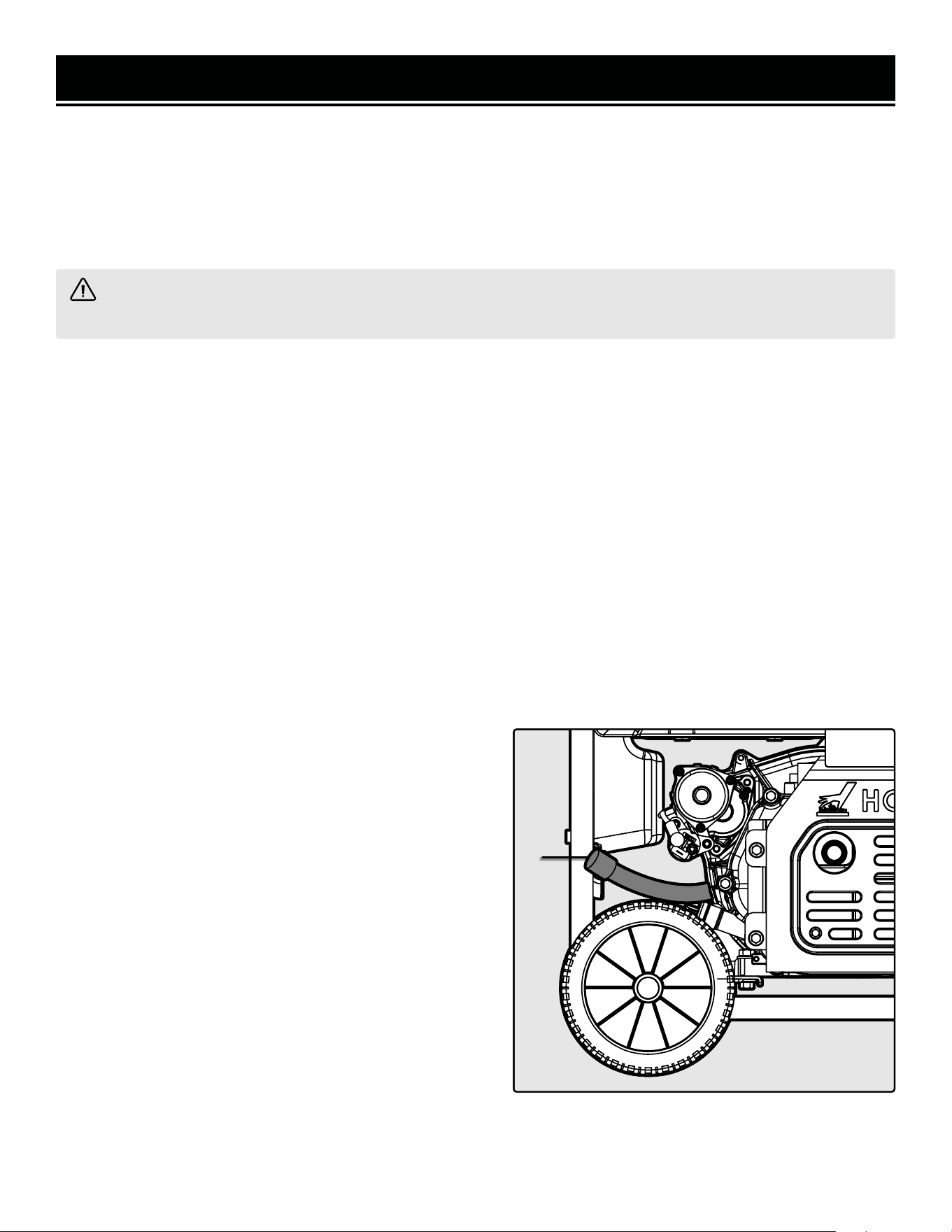
DRAINING / CHANGING OIL
Change the oil according to the Recommended Maintenance Schedule in Table 4. Change the oil more often if
operating under heavy load or high ambient temperatures. It is also necessary to drain the oil from the crankcase if
it has become contaminated with water or dirt. Changing the oil when the engine is warm allows for more-complete
drainage.
To change engine oil:
1. Prepare an approved oil-storage container underneath the oil drainage hose (Fig. 20 - 1) to catch oil as it drains.
Fig. 20
1
MAINTENANCE
WARNING! Never clean the generator when it is running! Never clean with a bucket of water or a hose. Water
can get inside the working parts of the generator and cause corrosion or a short circuit.
CLEANING YOUR GENERATOR
Keep the generator clean to prevent improper operation or machine damage from dirt and debris. Inspect all ventila-
tion openings on the generator. These openings must be kept clean and unobstructed.
If the generator becomes dirty, use a damp cloth to wipe exterior surfaces. Use a soft bristle brush to loosen dirt and
oil and use a vacuum to pick up loose dirt. Use low pressure air (not to exceed 25 PSI) to blow away dirt.
CHECKING / ADDING OIL
Check the oil level before each use and every 8 hours of operation (refer to Table 4). The oil capacity of the gen-
erator engine is 37.2 fl oz (1.1 L). Add oil when the oil level is low. For the proper type and weight of oil refer to
Fig. 2. This is a critical step for proper engine starting. The generator is equipped with a with low-oil shut down to
protect it from running without oil.
To check the oil level and/or add oil refer to "Step 1 - Add/Check Oil."
NOTE: To avoid possible gasoline spills from the carburetor
bowl, drain the carburetor before draining oil.
2. Remove the oil drainage hose from its harness behind
the panel. Open the oil drainage valve by turning the lever,
and allow oil to drain from the engine completely.
3. Close the oil drainage valve after the oil has drained.
NOTE: Never dispose of used engine oil in the trash or down
a drain. Please call a local recycling center or auto garage to
arrange proper oil disposal.
4. Unscrew the oil dipstick. Using a funnel or appropriate
dispenser, add 37.2 fl oz of clean engine oil into the oil fill
until you can see oil coming up the threads of the oil fill. Do
not over fill.
5. Reinstall the oil dipstick and tighten it securely. Wipe
clean any oil spillage.
34
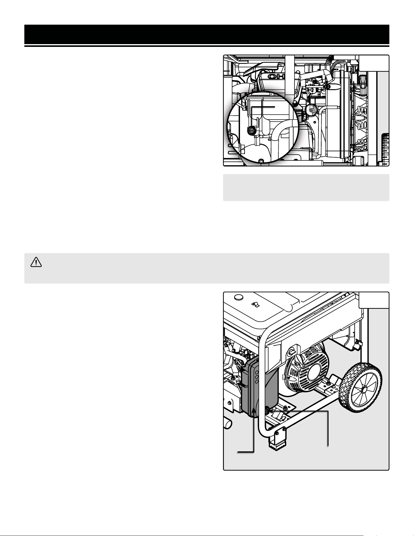
WARNING! Running the engine with a dirty, damaged or missing air filter element can result in danger to the
operator and cause the engine to wear out prematurely.
NOTE: Make sure to drain your carburetor before
storing the generator for long periods of time.
DRAINING THE CARBURETOR
Drain the carburetor after every use and before storing
the generator (refer to Table 4). Draining the carburetor can
help prevent build-up and blockages caused by stagnant fuel
inside of the carburetor.
1. Prepare an approved gasoline-storage container under
the carburetor to collect the drained fuel. Close fuel valve.
2. The carburetor can be accessed from the backside of the
generator between the engine and the air filter. To drain the
carburetor, open up the carburetor drain screw (Fig. 21 - 1)
with a Phillips-head screwdriver (not included) and drain out
any gasoline that has built up inside.
3. Once the fuel has drained, close the drain screw.
INSPECTING/CLEANING THE AIR FILTER
Inspect and clean the air filter every 50 hours of operation (refer to Table 4). Routine maintenance of the air filter
helps maintain proper airflow to the carburetor. Occasionally check that the air filter is free of excessive dirt. Clean
air filter more frequently in dirty or dusty conditions.
1. Remove the air filter cover (Fig. 22 - 1) by unscrewing the
cover lock knob (Fig. 22 - 2) at the bottom of the air filter
cover.
2. Remove the foam, sponge-like air filter element from the
casing. Wipe excessive oil and any dirt from inside of the air
filter casing.
3. Check the foam, sponge-like air filter element.
a) Good elements can be washed in soapy water. Dry the
element in clean cloth (do not twist it). Add a few drops
of engine oil to the air filter element and spread it evenly.
A small amount of oil left in the element is normal and
necessary for the engine to work properly.
b) Damaged elements should be replaced with a new
one. Replacement air filters can be purchased from
wenproducts.com.
4. Reinstall the air filter element and air filter cover.
MAINTENANCE
1
2
2
Fig. 21
Fig. 22
35
1
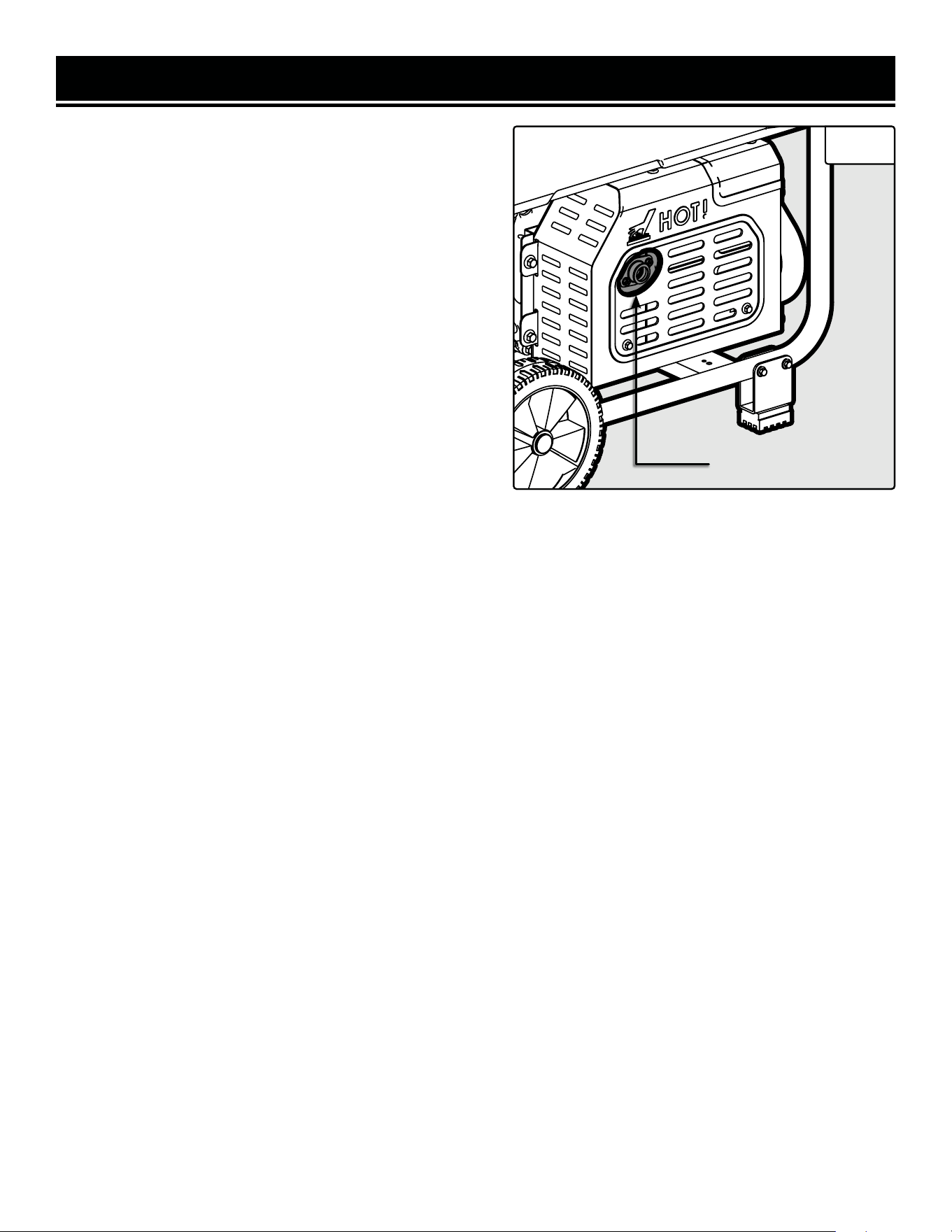
INSPECTING/CLEANING THE SPARK ARRESTOR
Inspect and clean the spark arrestor every 100 hours of
operation (refer to Table 4). The spark arrestor is located
outside the muffler, which gets very hot during operation.
Allow the engine to cool completely before servicing the
spark arrestor.
1. Remove the two bolts that secure the spark arrestor to
the muffler. See Fig. 23.
2. Remove the spark arrestor screen.
3. Carefully clean and remove the carbon deposits from the
spark arrestor screen with a wire brush. Replace the spark
arrestor if it is damaged. Replacement spark arrestors can
be purchased from wenproducts.com.
4. Reinstall the spark arrestor in the muffler and secure it in
place with the screws.
SPARK PLUG MAINTENANCE
Inspect and change the spark plug every 100 hours of operation (refer to Table 4). The spark plug is important
for proper engine operation. Check the spark plug regularly to maintain proper engine operation. A good spark plug
should be intact, free of deposits, and properly gapped.
1. Gently pull on the spark plug boot to remove it. Be careful not to tear insulation or wire.
2. Use the included spark plug wrench (slide the handle into the hole on the wrench) to unscrew the spark plug from
the engine. Remove the spark plug from the engine. TIP: There is limited space for the wrench to turn. Use both
rows of holes in the spark plug wrench to gain leverage to loosen the plug.
3. Visually inspect the spark plug. If it is cracked or chipped, or if the electrodes are worn or burned, discard it and
replace with a new spark plug. We recommend replacing it with an F7RTC (NGK BPR7ES) spark plug. These can be
purchased from wenproducts.com (part no. DF875iX-0215).
4. If re-using the spark plug, use a wire brush to clean any dirt from around the spark plug base, then re-gap the
spark plug.
Instructions continue on the next page.
MAINTENANCE
Spark Arrestor
Fig. 23
36
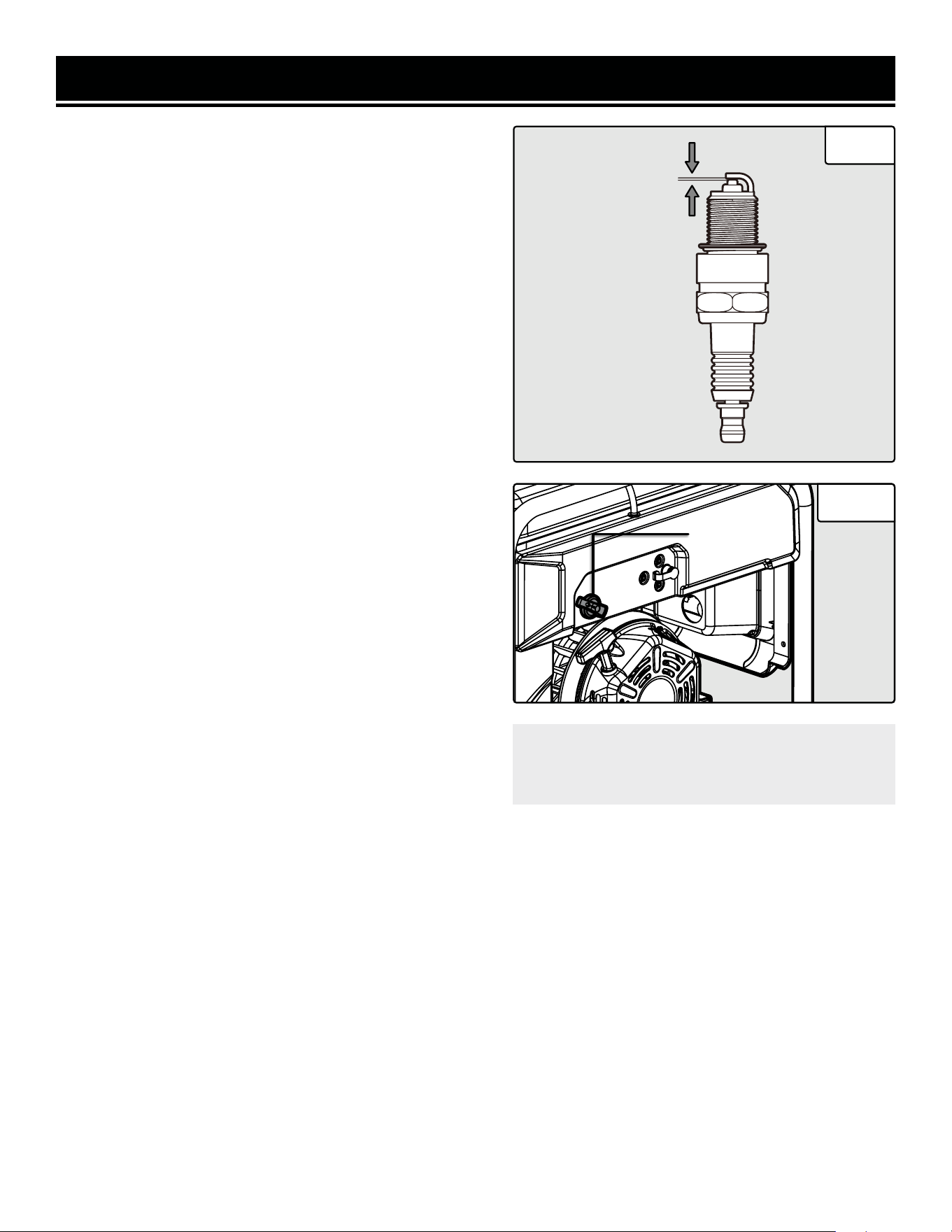
MAINTENANCE
5. Measure the plug gap with a spark plug gap gauge. The
gap should be 0.7 to 0.8 mm (0.028-0.031 in). Carefully
adjust the gap if necessary. See Fig. 24.
6. Screw the spark plug back into the spark plug hole us-
ing the spark plug wrench. Do not over-tighten spark plug.
Recommended tightening of the spark plug is ½ to ¾ of a
turn (15 ft-lb torque/20.33 Nm) after the spark plug gasket
contacts the spark plug hole.
7. Reinstall the spark plug boot over the spark plug.
DRAINING THE FUEL TANK
Drain and clean the fuel tank each year, or before storing
the generator for longer than two months.
1. Prepare an approved gasoline-storage container to collect
the drained fuel. Place it near the fuel selector switch (Fig.
25 - 1).
2. Turn the fuel selector switch to the PROPANE position.
3. Locate the fuel line between the fuel selector switch and
the carburetor. Disconnect the fuel line from the fuel selector
switch.
NOTE: A small amount of fuel may leak from the fuel line
during removal.
4. Place a funnel below the fuel selector switch opening, and
direct the other end of the funnel over the prepared con-
tainer.
5. Turn the fuel selector switch to the GASOLINE position to
start draining the fuel from the fuel selector switch opening.
NOTE: The draining process may take a few hours, depend-
ing on the amount of fuel in your gas tank.
6. Once the fuel is completely drained, turn the fuel selector
switch to the PROPANE position.
7. Start and run the engine until the fuel runs out.
8. Drain the carburetor. Refer to "Draining The Carburetor."
CAUTION! Store the emptied gasoline in a suit-
able place. Never store fuel for more than 2
months.
0.7 - 0.8mm
Fig. 24
Fig. 25
1
37

BATTERY MAINTENANCE/STORAGE
The battery will receive charge when the engine is running. Remember to run the generator once a month for 20-30
minutes to charge the battery. A charged battery will allow you to start the generator during your next time of need.
IMPORTANT! If you do not plan to use the generator for a long period of time, we recommend DISCON-
NECTING the negative battery cable from the battery to protect the battery from losing charge. After disconnect-
ing the cable, cover the free end with an insulator such as electrical tape. You may also choose to use a trickle
charger (not included) to maintain battery charge.
WARNING! It is best to store the battery indoors at room temperature. Do not store your battery outside in
the winter, where temperatures may go below 25°F (-5°C), or in any location where temperatures may exceed
104°F (40°C), such as in direct sunlight or inside a vehicle or metal building during the summer.
MAINTENANCE
Lithium-ion batteries can be damaged or suffer a shortened lifespan if they are charged in very cold temperatures
(below freezing). If you expect to store the generator in temperatures below 25°F (-5°C), we recommend removing
the battery from the generator and storing it indoors. If using the generator in temperatures below 25°F (-5°C), we
recommend running the generator for at least 15 minutes with the battery removed, or the negative (black) battery
cable disconnected and covered with an insulator such as electrical tape, and then connecting the battery. This will
allow the area around the generator to warm up, and will greatly reduce the chance of damage to the battery.
NOTE: Always recycle used batteries in accordance with local laws and regulations. Contact your local solid waste
collection site or recycling facility to obtain information on local recycling processes.
38
TRANSPORTATION & STORAGE
WARNING! Avoid direct sunlight inside a vehicle. If the generator is left in an enclosed vehicle for many
hours, the high temperature could cause the fuel to vaporize and result in a possible explosion.
TRANSPORTING THE GENERATOR
To prevent fuel spillage when transporting, be sure to perform the following:
1. Tighten the fuel cap and turn the fuel valve to the OFF position.
2. Flip the engine switch to the STOP position.
3. Drain the fuel tank if possible. Refer to "Draining The Fuel Tank."
4. Keep the generator upright. Never place the generator on its side or upside down - doing so could damage the
internal components of the generator and make it difficult to start.
STORING THE GENERATOR
Shut off the generator and allow the unit to cool to room temperature before storing it. NEVER place any type of
storage cover on the generator while it is still hot. Do not obstruct any ventilation openings.
WARNING! Store the generator upright in a cool and dry location, away from sources of heat, open flames,
sparks or pilot lights.
Follow the procedures below for properly storing your generator.
We highly recommend running your generator once a month for
20 to 30 minutes. Plug in a small load in to ensure there is proper
power output.
Please recycle the packaging and electronic components where facilities exist. Please contact your
local auto garage or recycling facility to properly dispose of oil/fuel.
TIP: Your WEN generator is compatible with
WEN 56409 and WEN GNC875 Generator
Covers (not included). They are available
for purchase at wenproducts.com.
PRODUCT DISPOSAL
Do not dispose of used generator or parts with your household waste. This product contains electrical or electronic
components that should be recycled. Please take this product to your local recycling facility for responsible disposal
to minimize its environmental impact.
Do not dispose of used oil or fuel in the trash or down a drain. Please contact your local recycling center or auto
garage to arrange proper oil/fuel disposal.
For Short Periods (30 to 60 Days):
• Drain the carburetor. Refer to "Draining The Car-
buretor."
• Add fuel stabilizer: Follow suggested portions
and instructions of your preferred stabilizer. Run
engine for 15 to 20 minutes, allowing fuel stabiliz-
er to mix with the gasoline and circulate through
the carburetor, and then top off with fuel. Filling
the fuel tank full reduces the amount of air in the
tank and helps fight deterioration of fuel.
For Extended Periods (Over 60 Days):
• Disconnect the negative lead from the battery.
Refer to "Battery Maintenance/Storage."
• Drain fuel tank and carburetor. Refer to "Draining
The Fuel Tank" and "Draining The Carburetor."
• Never store generator with fuel in the tank for
more than two months.
• Change engine oil. Refer to "Checking/Adding Oil."
39
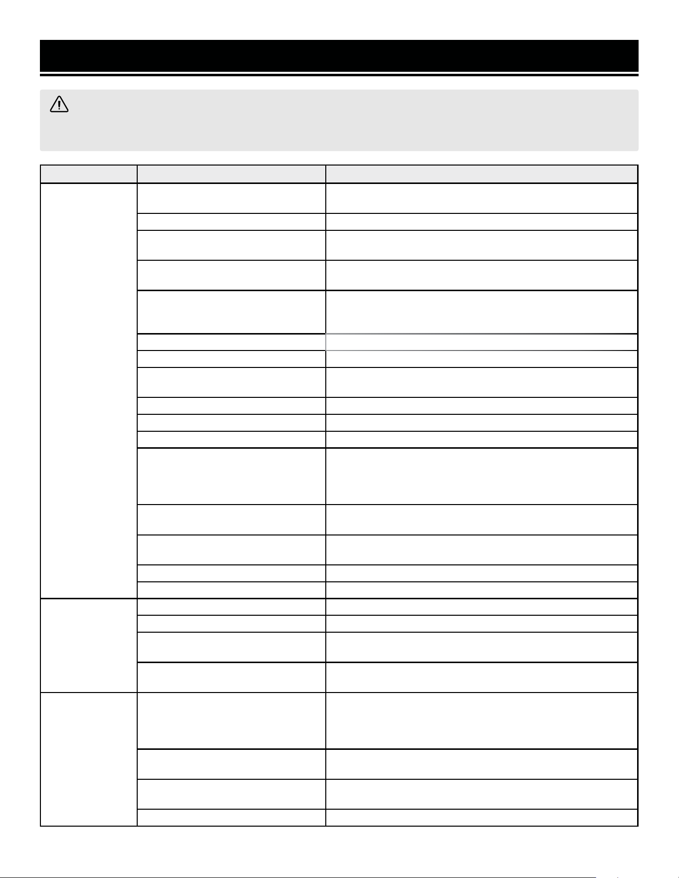
WARNING! Stop using the generator immediately if any of the following problems occur or risk serious
personal injury. If you have any questions, please contact customer service at 1-847-429-9263 (M-F 8-5 CST),
or email [email protected].
TROUBLESHOOTING GUIDE
PROBLEM POSSIBLE CAUSE SOLUTION
Engine will not
start.
1. Fuel selector switch is in wrong posi-
tion.
1. Set fuel selector switch to match fuel being used.
2. Battery switch is set to OFF (0). 2. Set battery switch to ON (1).
3. Engine has not been primed (LPG
only).
3. Prime the engine.
4. Battery is dead.
4. Electric and remote start will not work if battery is out of power.
Start generator using the recoil start to charge the battery.
5. Battery is too cold.
5. Electric start may be difficult if the battery is too cold. Store the
generator or battery in a warmer location. Start generator using
recoil start to warm up area around generator.
6. Oil is low. 6. Add oil.
7. Engine is out of fuel. 7. Add fuel.
8. Engine is filled with contaminated or
old fuel.
8. Drain fuel in the tank and carburetor. Replace with fresh fuel. Clean
carburetor if necessary.
9. Spark plug boot is disconnected. 9. Replace spark plug boot on spark plug.
10. Spark plug is dirty or broken. 10. Clean or replace spark plug. Re-gap if needed.
11. Propane tank is turned OFF. 11. Dang it, Bobby, I told you to turn that thing on!
12. Carburetor is air locked.
12. Set fuel selector switch to "PROPANE". Remove fuel solenoid
valve and bolt from bottom of the carburetor. Take off the carburetor
bowl to allow it to reset. Replace carburetor bowl and reinstall the
bolt, then reinstall the solenoid valve.
13. Onboard propane regulator is stuck.
13. Turn OFF propane tank. Disconnect hose from propane fitting.
Contact WEN customer service for assistance.
14. CO levels are too high.
14. Move the generator to an open area with fresh air. Wait a few
minutes for the CO buildup to dissipate.
15. CO sensor is disconnected. 15. Make sure CO sensor is connected.
16. Ghost in the generator. 16, Persuade ghost to leave. Consult Bill Murray if needed.
Engine will not
start (remote
start).
1. Remote is out of range. 1. Move closer to generator and point the remote at the generator.
2. Remote battery is dead. 2. Replace the remote battery (CR2032).
3. Generator and remote are not paired.
3. Pair remote and generator. See "PAIRING THE REMOTE AND
GENERATOR" section.
4. Other cause (see "engine will not start"
above).
4. Resolve other cause.
Engine runs, but
there is no electri-
cal output.
1. Circuit breaker has been tripped due
to overload, or the inverter has cut off
power to protect itself.
1. Turn off and unplug electrical device(s). Wait 5 minutes, then
press the circuit breaker button (or reset button) to reset. Check
the total wattage of the devices and reduce the load if it exceeds the
capacity of the generator. Then plug the loads back in one by one.
2. Bad connecting cords/wires.
2. Check the power cords and extension cords. Do not use if any
cord is damaged. Replace damaged cords immediately.
3. Bad electrical device connected to the
generator.
3. Try connecting a different device.
4. Internal generator problem. 4. Consult Table 2 for troubleshooting the overload light.
40
TROUBLESHOOTING GUIDE
WARNING! Stop using the generator immediately if any of the following problems occur or risk serious
personal injury. If you have any questions, please contact customer service at 1-847-429-9263 (M-F 8-5 CST),
or email [email protected].
IMPORTANT: Repairs and replacements should only be performed by an authorized technician. Parts and acces-
sories that wear down over the course of normal use are not covered by the two-year warranty.
PROBLEM POSSIBLE CAUSE SOLUTION
Generator runs but does
not support all electrical
devices connected.
1. Generator is overloaded.
1. Turn off and unplug electrical device(s). Wait 5 minutes, then
press the circuit breaker button (or reset button) to reset. Check
the total wattage of the devices and reduce the load if it exceeds the
capacity of the generator. Then plug the loads back in one by one.
2. Short circuit in one of the
devices.
2. Try disconnecting any faulty or short-circuited electrical loads.
3. Air filter is dirty.
3. Clean or replace the air filter element. Refer to "INSPECTING/
CLEANING THE AIR FILTER."
Engine is "hunting" during
operation (engine RPM is
fluctuating).
NOTE: Turn off the genera-
tor and wait for it to cool
down before performing
the maintenance
solutions.
1. Fuel isn't running through the
fuel selector switch.
1. Check if the fuel is properly and consistently going through the
fuel selector switch.
2. Fuel level is low. 2. Check fuel level.
3. The air filter is clogged.
3. Check for any blockage in the air filter. Check and clean the air
filter as necessary.
4. The muffler or spark arrester
is blocked.
4. Check if the spark arrester is blocked. Clean with metal brush as
necessary.
5. There is gunk in the carburetor
preventing a consistent fuel/air
mixture.
5. Use "gunk remover" spray on the carburetor jets.
41
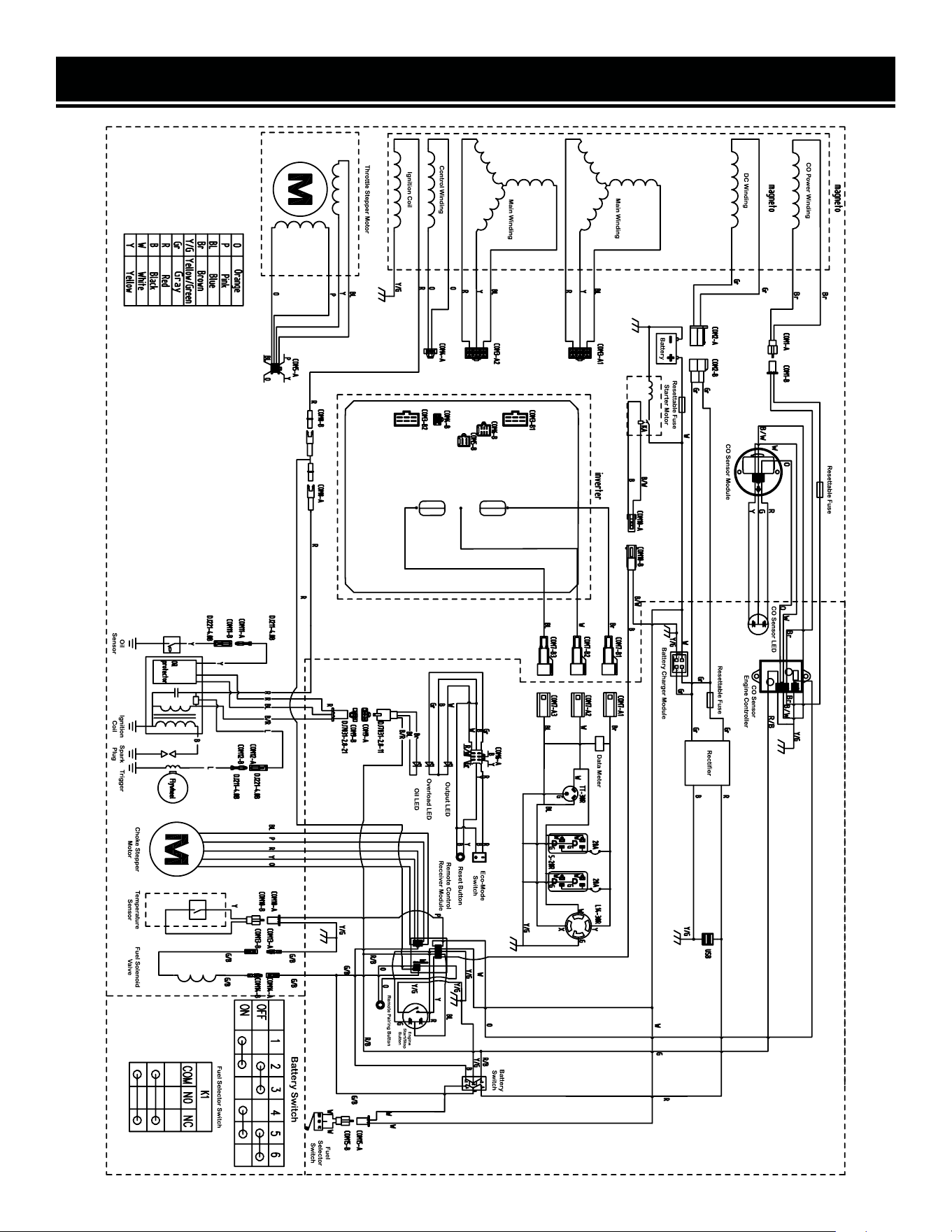
WIRING DIAGRAM
42
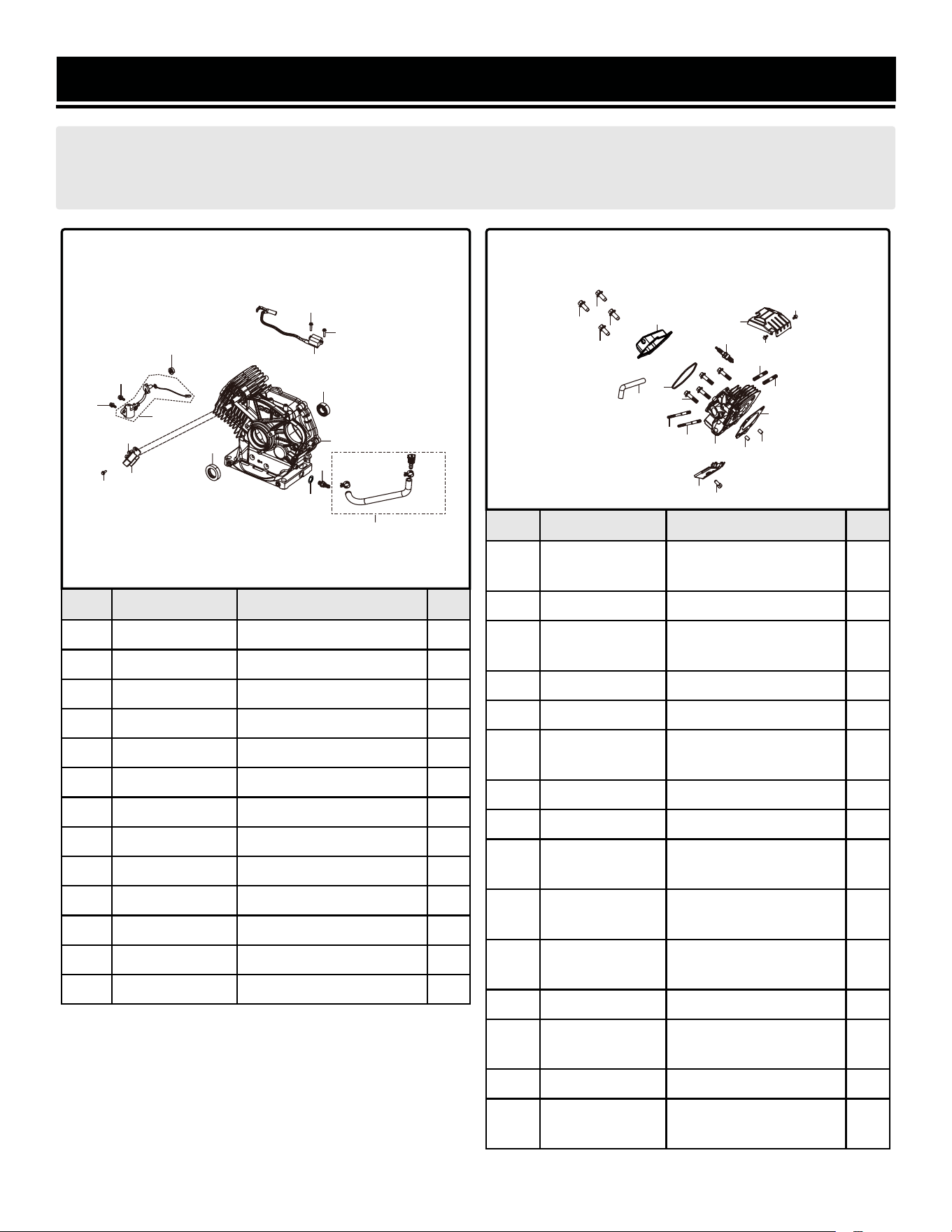
EXPLODED VIEW & PARTS LIST
NOTE: Replacement parts can be purchased from wenproducts.com, or by calling our customer service at
1-847-429-9263, M-F 8-5 CST. Parts and accessories that wear down over the course of normal use are not
covered by the two-year warranty. Not all parts may be available for purchase.
No. Part No. Description Qty.
1-1 GN875i-0101 Crankcase 1
1-2 GN875i-0102 Bearing, 6202P6 1
1-3 GN875i-0103 Oil Seal 1
1-4 GN625i-0204 Flat Washer, 12mm 1
1-5 GN875i-0105 Oil Drain Hose Fitting 1
1-6 GN625i-0205 Oil Drain Hose 1
1-7 GN625i-0207 Engine Oil Sensor 1
1-8 GN625i-0208 Bolt, M6x16 2
1-9 GN875i-0109 Nut, M10 1
1-10 GN400i-0910 Bolt, M5x16 2
1-11 DF875iX-0111 Trigger 1
1-12 DF875iX-0112 Ignition Coil 1
1-13 GN400i-0111 Bolt, M5x20 2
ASSEMBLY 1 - CRANKCASE
No. Part No. Description Qty.
2-1 GN875i-0201
Cylinder Body Shroud,
Primary
1
2-2 56200-1202 Bolt, M6x12 2
2-3 GN625i-0109
Cylinder Head Bolt,
M10x80
4
2-4 GN625i-0110 Pin 2
2-5 DF875iX-0205 Cylinder Head Gasket 1
2-6 DF875iX-0206
Cylinder Head
Subassembly
1
2-7 56310i-0109 Bolt, M8x34 2
2-8 GN875i-0208 Stud Bolt, M6/M8x110 2
2-9 GN875i-0209
Cylinder Body Shroud,
Secondary
1
2-10 DF875iX-0210
Cylinder Head Cover
Gasket
1
2-11 DF875iX-0211
Cylinder Head Cover
Bolt (M6x14)
4
2-12 DF875iX-0212 Temperature Sensor 1
2-13 DF875iX-0213
Cylinder Head Cover
Subassembly
1
2-14 DF875iX-0214 Breather Tube 1
2-15 DF875iX-0215
Spark Plug (Torch
F7RTC / NGK BPR7ES)
1
ASSEMBLY 2 - CYLINDER HEAD
SUBASSEMBLY, SPARK PLUG
43
1
3
5
6
4
2
7
8
8
9
11
10
10
12
13
13
11
13
5
15
6
7
8
3
14
1
2
2
4
7
8
9
4
10
11
11
11
12
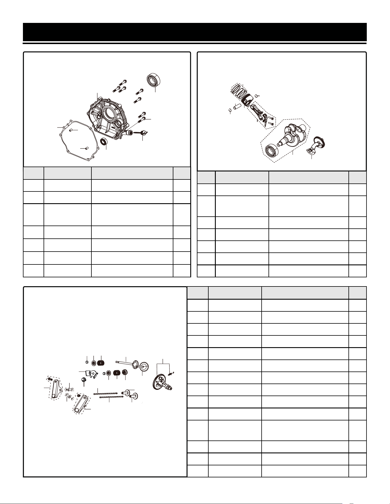
EXPLODED VIEW & PARTS LIST
No. Part No. Description Qty.
3-1 GN875i-0301 Crankcase Cover Gasket 1
3-2 GN875i-0302 Bearing, 6202P6 1
3-3 GN625i-0304
Oil Dipstick
Subassembly
1
3-4 GN875i-0304 Pin 2
3-5 GN875i-0305 Crankcase Cover 1
3-6 GN875i-0306 Bolt, M8x40 7
3-7 GN875i-0307 Bearing, 6207P53 1
ASSEMBLY 3 - CRANKCASE COVER
No. Part No. Description Qty.
4-1 GN875i-0401 Balance Shaft Assembly 1
4-2 GN875i-0402
Connecting Rod
Assembly
1
4-3 DF875iX-0403 Piston 1
4-4 GN875i-0404 Piston Pin 1
4-5 GN875i-0405 Piston Pin Clip 2
4-6 GN875i-0406 Piston Ring Set 1
4-7 GN875i-0407 Crankshaft Assembly 1
ASSEMBLY 4 - CRANKSHAFT,
CONNECTING ROD, BALANCING SHAFT
No. Part No. Description Qty.
5-1 DF875iX-0501 Camshaft Assembly 1
5-2 DF875iX-0502 Exhaust Valve 1
5-3 DF875iX-0503 Seal Guide 1
5-4 DF875iX-0504 Valve Spring 2
5-5 DF875iX-0505 Exhaust Valve Retainer 1
5-6 DF875iX-0506 Intake Valve Retainer 1
5-7 GN875i-0510 Valve Tappet 2
5-8 DF875iX-0508 Valve Lifter Subassembly 2
5-9 DF875iX-0509 Rocker Shaft Subassembly 2
5-10 DF875iX-0510 Valve Rocker 2
5-11 DF875iX-0511
Cylinder Head Cover Pin
Limit Plate
1
5-12 DF875iX-0512 Bolt, M6x12 1
5-13 DF875iX-0513 Valve Rotator 2
5-14 DF875iX-0514 Intake Valve 1
ASSEMBLY 5 - VALVE TRAIN,
CAMSHAFT SUBASSEMBLY
44
2
1
4
5
3
7
6
4
2
5
5
4
3
6
1
7
1
2
3
4
5
4
7
7
8
8
9
9
10
10
11
12
13
14
6
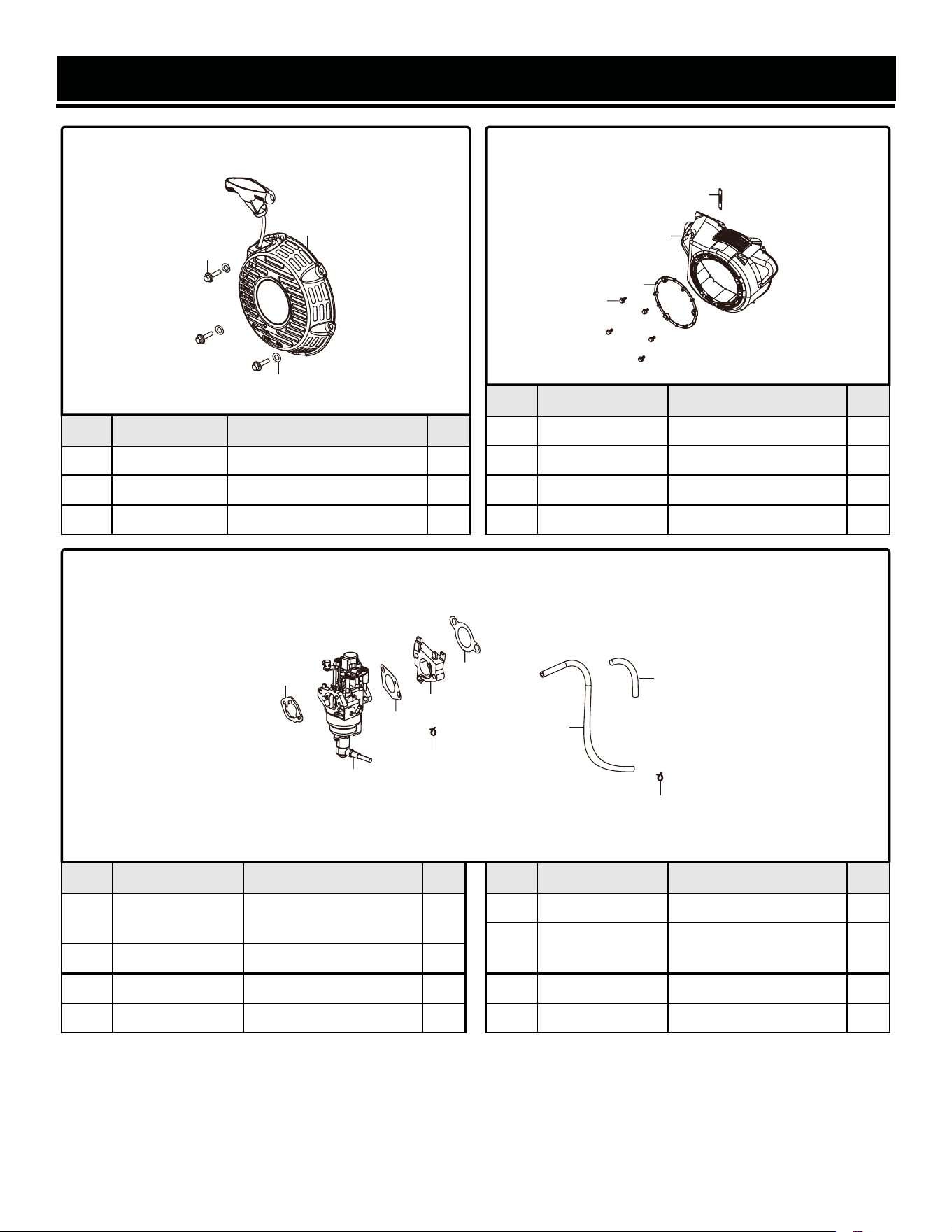
EXPLODED VIEW & PARTS LIST
No. Part No. Description Qty.
6-1 GN625i-0701 Bolt, M6x20 3
6-2 GN875i-0602 Recoil Starter Assembly 1
6-3 GN625i-0703 Flat Washer, 6mm 3
ASSEMBLY 6 - RECOIL STARTER
No. Part No. Description Qty.
7-1 56200-1202 Bolt, M6x12 5
7-2 GN625i-0802 Retaining Ring 1
7-3 GN875i-0703 Shroud 1
7-4 GN400i-0703 Clip 1
ASSEMBLY 7 - SHROUD, LOWER SHIELD
No. Part No. Description Qty.
8-1 DF875iX-0801
Carburetor Insulator
Gasket
1
8-2 GN625i-0901 Air Filter Gasket 1
8-3 DF875iX-0803 Carburetor Assembly 1
8-4 DF875iX-0804 Fuel Tube 1
ASSEMBLY 8 - CARBURETOR
No. Part No. Description Qty.
8-5 GN875i-0805 Carburetor Gasket 1
8-6 DF875iX-0806
Carburetor Insulator
Plate
1
8-7 GN625i-0907 Hose Clamp 2
8-8 DF875iX-0808 Rubber Jacket 1
45
1
2
3
2
3
4
1
1
6
5
3
2
7
4
7
8
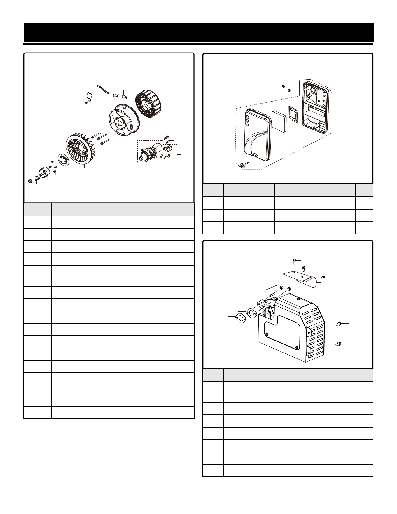
No. Part No. Description Qty.
9-1 DF875iX-0901 Rotor 1
9-2 DF875iX-0902 Stator 1
9-3 GN625i-0214 Wiring Clamp 1
9-4 GN875i-0904 Bolt, M5x10 1
9-5 GN625i-1101
Flywheel Nut, M16-
1.5
1
9-6 GN875i-0906 Wiring Sheath 1
9-7 GN875i-0907 Wiring Clip 2
9-8 GN625i-1103 Starter Pulley 1
9-9 56200-1202 Bolt, M6x12 3
9-10 56200-1202 Bolt, M6x12 4
9-11 DF875iX-0911 Starter Pulley Seat 1
9-12 DF875iX-0912 Impeller 1
9-13 GN875i-0913 Bolt, M6x65 3
9-14 GN875i-0914
Starter Motor
Assembly
1
9-15 GN875i-0915 Bolt, M8x25 2
ASSEMBLY 9 - FLYWHEEL, IMPELLER,
STARTER PULLEY
EXPLODED VIEW & PARTS LIST
No. Part No. Description Qty.
10-1 DF875iX-1001 Air Filter Assembly 1
10-2 56200-0506 Flanged Hex Nut, M6 2
10-3 GN875i-1003 Air Filter Element 1
ASSEMBLY 10 - AIR FILTER
ASSEMBLY 11 - MUFFLER ASSEMBLY
No. Part No. Description Qty.
11-1 GN625i-1205
Outer Muffler
Cover
1
11-2 GN625i-1206 Bolt, M6x12 3
11-3 GN400i-1108 Nut, M8 2
11-4 GN625i-1202 Muffler Gasket 2
11-5 GN875i-1105 Muffler Assembly 1
11-6 GN625i-1203 Bolt, M8x16 2
N.P. GN625i-1201.1 Spark Arrestor 1
46
9
10
5
11
8
12
13
1
2
3
4
6
7
7
14
15
2
3
1
5
4
6
6
3
1
2
4
2
2
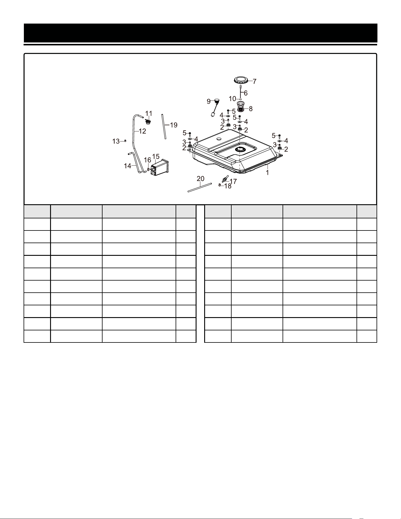
EXPLODED VIEW & PARTS LIST
No. Part No. Description Qty.
12-1 GN625i-1301 Fuel Tank 1
12-2 56380i-1207 Fuel Tank Damper 4
12-3 GN625i-1303 Bushing 4
12-4 GN625i-1304 Flat Washer, 6mm 4
12-5 GN625i-1305 Bolt, M6x25 4
12-6 GN400i-1214 Fuel Tank Cap Chain 1
12-7 GN400i-1202 Fuel Tank Cap 1
12-8 GN875i-1208 Fuel Strainer 1
12-9 GN400i-1204 Fuel Gauge Assembly 1
12-10 GN625i-1310 Fuel Tank Chain Clip 1
ASSEMBLY 12 - FUEL TANK
No. Part No. Description Qty.
12-11 GN400i-1205 Breather Valve 1
12-12 GN875i-1212 Breather Hose 1
12-13 GN400i-1316 Rubber Cover 1
12-14 GN875i-1214 Air Filter Hose 1
12-15 GN625i-1315 Carbon Tank 1
12-16 GN625i-1316 Hose Clamp A 1
12-17 GN625i-1317 Fuel Tank Outlet 1
12-18 GN625i-1318 Hose Clamp B 1
12-19 GN625i-1319 Rubber Cover 1
12-20 DF875iX-1220 Fuel Tube 1
47
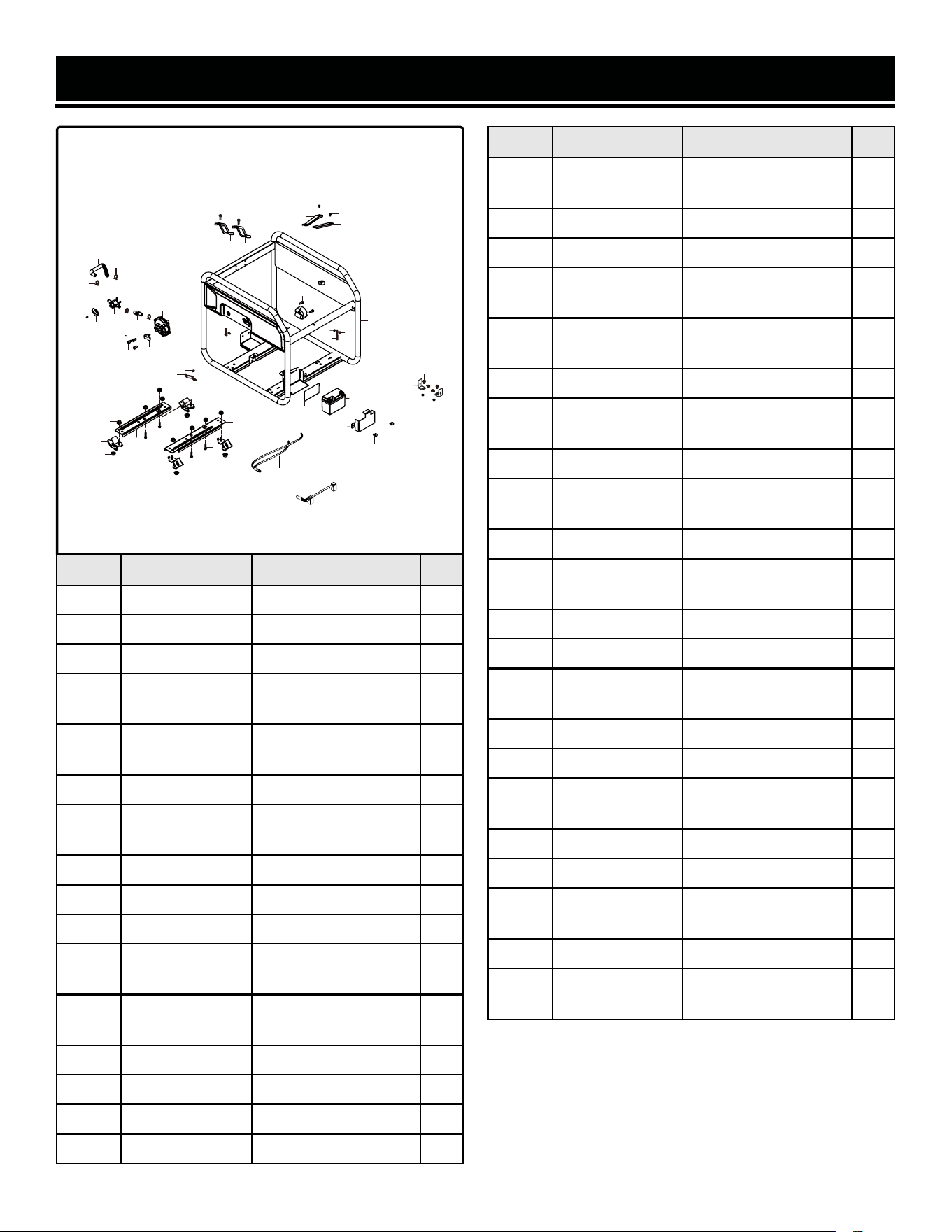
EXPLODED VIEW & PARTS LIST
No. Part No. Description Qty.
13-1 DF875iX-1301 Frame Assembly 1
13-2 GN625i-1402 Nut, M10-1.25 8
13-3 56310i-1404 Nut, M8 4
13-4 GN875i-1304
Engine Support
Bracket 1
1
13-5 GN875i-1305
Engine Support
Bracket 2
1
13-6 GN625i-1406 Bolt, M10-1.25x40 4
13-7 GN875i-1307
Engine Frame
Damper
4
13-8 GN875i-1308 Air Filter Support 1
13-9 56200-1202 Bolt, M6x12 1
13-10 56200-1202 Bolt, M6x12 4
13-11 GN875i-1311
Inverter Support
Bracket 1
1
13-12 GN875i-1312
Inverter Support
Bracket 2
1
13-13 56200-0706 Bolt, M6x10 2
13-14 GN400i-1311 Bolt, M6x8 1
13-15 GN625i-1415 Cllp 2
13-16 GN400i-1313 Nut, M6 1
ASSEMBLY 13 - FRAME
No. Part No. Description Qty.
13-17 56380i-1304
Battery (Li-ion, 12V,
1.6Ah)
1
13-18 GN875i-1318 Battery Clamp 1
13-19 56200-1202 Bolt, M6x12 2
13-20 GN875i-1320B
Quick-Connector
Wiring, Battery
1
13-21 GN875i-1321B
Quick-Connector
Wiring, Motor
1
13-22 DF875iX-1322 Fuel Selector Switch 1
13-23 DF875iX-1323
Fuel Selector Switch
Handle
1
13-24 DF875iX-1324 LPG Hose 1 1
13-25 DF875iX-1325
Secondary LPG
Regulator
1
13-27 DF875iX-1326 LPG Hose 2 1
13-30 GN625i-1430
Shipping Bracket
(Red)
2
13-31 GN400i-1104 Bolt, M8x16 4
13-32 GN625i-1432 Nut, M8 2
13-33 GN875i-1333
Inverter Support
Bracket 3
2
13-34 GN875i-1334 Insulator Plate 1
13-35 DF875iX-1335 Hose Clamp 3
13-36 DF875iX-1336
Socket Head Cap
Screw, M6x10
3
13-37 DF875iX-1337 LPG Inlet Cover 1
13-38 GN625iX-1430 CO Sensor Module 1
13-39 GN875iX-1332
Security Torx Screw,
M4x25
2
13-40 DF875iX-1340 Hose Clamp 1
13-41 DF875iX-1341
Phillips-Head Screw,
M4x10
1
48
39
38
23
22
35
19
18
17
34
1
32
30
31
6
5
2
3
4
8
9
14
15
16
13
24
25
7
36
37
41
33
33
27
10
11
12
40
21
20
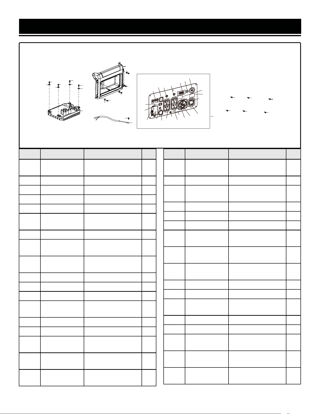
EXPLODED VIEW & PARTS LIST
No. Part No. Description Qty.
14-1
DF875iX-
1401ASM
Control Panel
Assembly
1
14-2 GN625i-1502 Bolt, M6x16 4
14-3 GN625i-1503 Bolt, M6x20 4
14-4 GN625i-1504 Flat Washer, 6mm 4
14-5 GN875i-1405 Inverter 1
14-6 GN625i-1506
Screw & Washer,
M5x10
6
14-7 GN625i-1507 Panel Seat 1
14-8 DF875iX-1408
Indicator Light
Assembly
1
14-9 DF875iX-1409
Engine Start/Stop
Button
1
14-10 GN625i-1510 AC Breaker, 20A 2
14-11 DF875iX-1411 Multi-Meter 1
14-12 DF875iX-1412 Battery Switch 1
14-13 DF875iX-1413
CO Sensor LED
Indicator
1
14-14 GN400i-1413 Grounding Nut 1
14-15 GN625i-1515 USB Outlet Assembly 1
14-16 56380i-1421
NEMA 5-20R Duplex
Outlet
2
14-17 GN625i-1516
NEMA 5-20R Outlet
Cover
2
14-18 GN400i-1418B
NEMA TT-30R RV
Outlet
1
ASSEMBLY 14 - CONTROL PANEL
No. Part No. Description Qty.
14-19 GN625i-1518
NEMA TT-30R Outlet
Cover
1
14-20 56380i-1422 ECO-Mode Switch 1
14-21 GN625i-1521
NEMA L14-30R Outlet
Cover
1
14-22 DF875iX-1422 Rectifier Bridge 1
14-23 DF875iX-1423 Remote Pairing Button 1
14-24 GN625i-1524 NEMA L14-30R Outlet 1
14-25 DF875iX-1425
CO Sensor Engine
Control Module
1
14-26 DF875iX-1426
Remote Control
Receiver Module
1
14-27 DF875iX-1427
Control Panel Wiring
Harness
1
14-28 DF875iX-1428 Hex Bolt, M6x10 1
14-29 DF875iX-1429 Large Washer, 6mm 4
14-30 DF875iX-1430
Battery Charger
Module
1
14-31 DF875iX-1431 Reset Button 1
N.P. DF875iX-1432 Remote Control 1
N.P. DF875iX-1433
Primary LPG Regulator
Hose Assembly
1
N.P. DF875iX-HA36
High Altitude Kit, 3000
- 6000 ft
1
N.P. DF875iX-HA68
High Altitude Kit, 6000
- 8000 ft
1
49
2
2
3
4
5
3
4
3
4
3
4
7
8
9
10
10
11
24
21
19
18
17
16
15
20
14
13
12
25
6
6
6
6
6
6
2
1
26
27
28
29
23
30
31
22
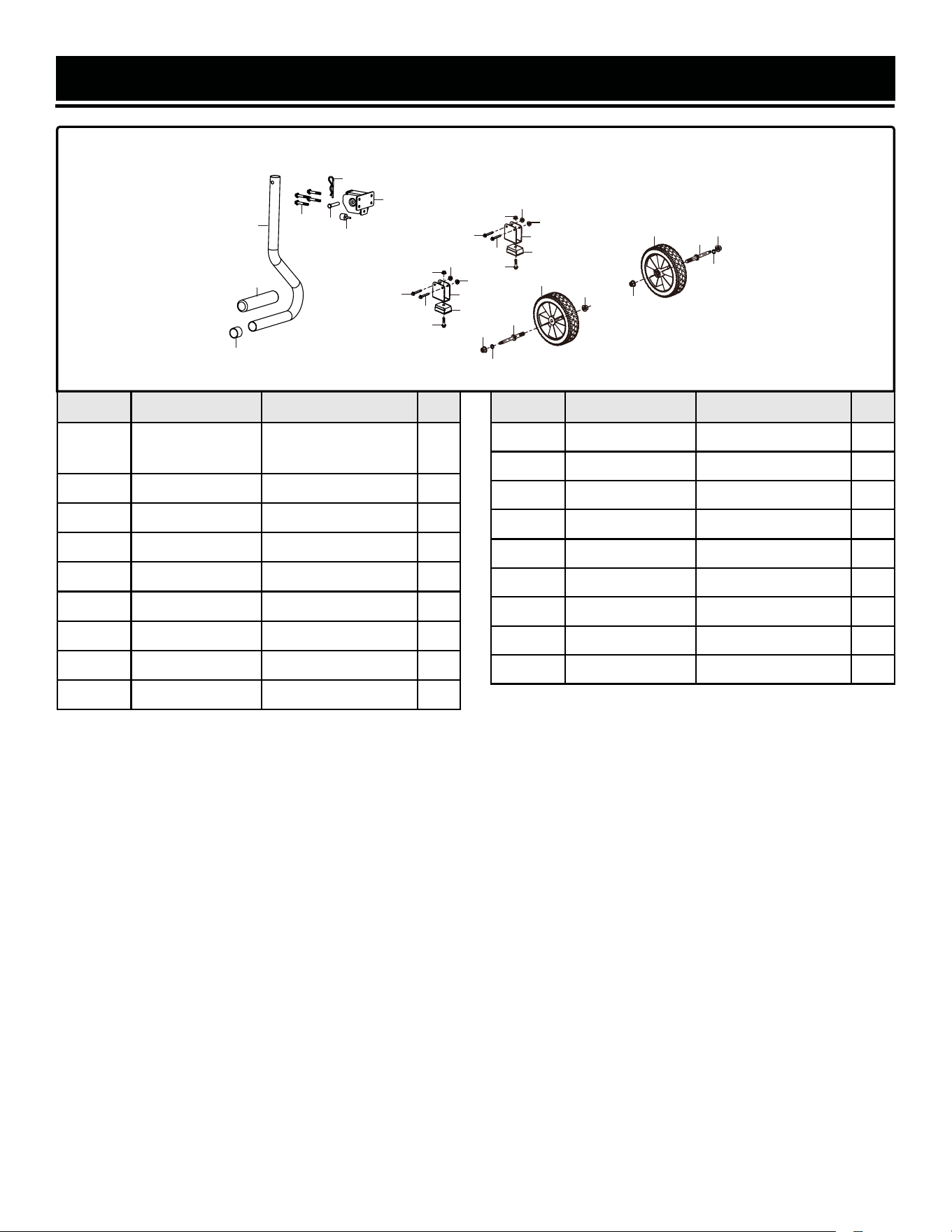
No. Part No. Description Qty.
15-1 GN625i-1601
Handle Tube
Assembly
1
15-2 GN625i-1602 Handle Sleeve 1
15-3 GN625i-1603 R-clip 1
15-4 GN625i-1604 Bolt, M6x30 4
15-5 GN625i-1605 Handle Bracket 1
15-6 GN625i-1606 Handle Pin 1
15-7 GN625i-1607 Handle Damper 1
15-8 GN625i-1608 Nut, M8 2
15-9 GN625i-1609 Nut, M12-1.25 2
ASSEMBLY 15 - WHEEL AND HANDLE
EXPLODED VIEW & PARTS LIST
No. Part No. Description Qty.
15-10 GN625i-1610 Axle 2
15-11 GN625i-1611 Wheel 2
15-12 GN625i-1612 Bolt, M6x40 4
15-13 56200-0506 Nut, M6 6
15-14 GN625i-1614 Foot Bracket 2
15-15 GN625i-1615 Foot Base 2
15-16 56310I-1420 Bolt, M6x25 2
15-17 GN625i-1617 Handle Tube Plug 1
15-18 GN625i-1618 Flat Washer, 8mm 2
50
8
12
12
13
13
14
15
12
12
16
16
13
13
8
9
9
10
10
11
11
13
13
14
15
1
2
3
4
5
6
7
17
18
18

WARRANTY STATEMENT
51
WEN Products is committed to building tools that are dependable for years. Our warranties are consistent with this
commitment and our dedication to qualit
y.
LIMITED WARRANTY OF WEN PRODUCTS FOR HOME USE
GREA
T LAKES TECHNOLOGIES, LLC (“Seller”) warrants to the original purchaser only, that all WEN consumer power
tools
will be free from defects in material or workmanship during personal use for a period of two (2) years from
date
-
fessional or commer
cial use. Purchaser has 30 days from the date of purchase to report missing or damaged parts.
SELLER’S SOLE OBLIG
ATION AND YOUR EXCLUSIVE REMEDY under this Limited Warranty and, to the extent per-
mitted
by law, any warranty or condition implied by law, shall be the replacement of parts, without charge, which are
defective
in material or workmanship and which have not been subjected to misuse, alteration, careless handling,
misrepai
r, abuse, neglect, normal wear and tear, improper maintenance, improper storage, incorrect lubricants/
fuels,
or other conditions adversely affecting the Product or the component of the Product, whether by accident or
intentionall
y, by persons other than Seller. To make a claim under this Limited Warranty, you must make sure to
keep
-
chase. Place of Pur
chase must be a direct vendor of Great Lakes Technologies, LLC. Pur
chasing through third party
vendors,
including but not limited to garage sales, pawn shops, resale shops, or any other secondhand merchant,
voids the warranty included with this product. Contact [email protected] or 1-847-429-9263 with the
following
information to make arrangements: your shipping address, phone number, serial number, required part
numbers, and proof of pur
chase. Damaged or defective parts and products may need to be sent to WEN before the
replacements can be shipped out.
-
turning
a product for warranty service, the shipping charges must be prepaid by the purchaser. The product must
be
shipped in its original container (or an equivalent), properly packed to withstand the hazards of shipment. The
product
must be fully insured with a copy of the proof of purchase enclosed. There must also be a description of
the
will be returned and shipped back to the pur
chaser at no charge for addresses within the contiguous United States.
THIS
LIMITED WARRANTY DOES NOT APPLY TO ITEMS THAT WEAR OUT FROM REGULAR USAGE OVER TIME,
INCLUDING
FILTERS, SPARK PLUGS, VOLTAGE REGULATORS, BRUSHES, GASKETS, O-RINGS, WHEEL KITS, BAT-
TERIES,
RECOIL STARTERS, HIGH PRESSURE HOSES, SPRAY GUNS, ETC. ANY IMPLIED WARRANTIES SHALL
BE
LIMITED IN DURATION TO TWO (2) YEARS FROM DATE OF PURCHASE. SOME STATES IN THE U.S. AND
SOME
CANADIAN
PROVINCES DO NOT ALLOW LIMITATIONS ON HOW LONG AN IMPLIED WARRANTY LASTS, SO THE
ABOVE LIMIT
ATION MAY NOT APPLY TO YOU.
IN
NO EVENT SHALL SELLER BE LIABLE FOR ANY INCIDENTAL OR CONSEQUENTIAL DAMAGES (INCLUDING BUT
NOT
LIMITED TO LIABILITY FOR LOSS OF PROFITS) ARISING FROM THE SALE OR USE OF THIS PRODUCT. SOME
ST
ATES IN THE U.S. AND SOME CANADIAN PROVINCES DO NOT ALLOW THE EXCLUSION OR LIMITATION OF IN-
CIDENT
AL OR CONSEQUENTIAL DAMAGES, SO THE ABOVE LIMITATION OR EXCLUSION MAY NOT APPLY TO YOU.
THIS
LIMITED WARRANTY GIVES YOU SPECIFIC LEGAL RIGHTS, AND YOU MAY ALSO HAVE OTHER
RIGHTS
WHICH
VARY FROM STATE TO STATE IN THE U.S., PROVINCE TO PROVINCE IN CANADA AND FROM COUNTRY
TO COUNT
RY.
THIS
LIMITED WARRANTY APPLIES ONLY TO ITEMS SOLD WITHIN THE UNITED STATES OF AMERICA, CANADA
AND
THE COMMONWEALTH OF PUERTO RICO. FOR WARRANTY COVERAGE WITHIN OTHER COUNTRIES, CON-
T
ACT THE WEN CUSTOMER SUPPORT LINE. FOR WARRANTY PARTS OR PRODUCTS REPAIRED UNDER WAR-
RANTY
SHIPPING TO ADDRESSES OUTSIDE OF THE CONTIGUOUS UNITED STATES, ADDITIONAL SHIPPING
CHARGES MAY APPLY.

THANKS FOR
REMEMBERING
V. 2022.10.31
