IMPORTANT: Your new tool has been engineered and manufactured to WEN’s highest standards for dependability,
ease of operation, and operator safety. When properly cared for, this product will supply you years of rugged,
trouble-free performance. Pay close attention to the rules for safe operation, warnings, and cautions. If you use
your tool properly and for its intended purpose, you will enjoy years of safe, reliable service.
NEED HELP? CONTACT US!
Have product questions? Need technical support? Please feel free to contact us:
TECHSUPPOR[email protected]1-847-429-9263 (M-F 8AM-5PM CST)
For replacement parts and the most up-to-date instruction manuals, visit WENPRODUCTS.COM
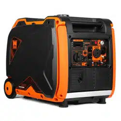
4500W DUAL FUEL
INVERTER GENERATOR
Instruction Manual
MODEL DF452iX

CONTENTS
WELCOME 3
Specifications ....................................................................................................3
Introduction ......................................................................................................4
SAFETY 5
Safety Information ............................................................................................5
Generator Safety Warnings ...............................................................................6
9
Unpacking & Packing List .................................................................................9
Know Your Inverter Generator .........................................................................10
Generator Preparation .....................................................................................12
BEFORE OPERATING
OPERATION & MAINTENANCE 20
Starting Your Generator ..................................................................................20
Using Your Generator ......................................................................................26
Shutting Off Your Generator ............................................................................33
Maintenance ....................................................................................................35
Transportation & Storage ................................................................................43
Troubleshooting Guide ....................................................................................44
Wiring Diagram ...............................................................................................45
Exploded View & Parts List .............................................................................46
Warranty Statement ........................................................................................57
To purchase accessories for your tool, visit WENPRODUCTS.COM
Magnetic Oil Dipstick (Model 55201)
WEN Parallel Connection Kit
Weatherproof Generator Cover (Model 56310iC)
High-Altitude Kit (Part DF400i-HA36 & DF400i-HA68)
2
SPECIFICATIONS
Rated Wattage Gasoline: 3500 Watts; LPG: 3150 Watts
Surge Wattage Gasoline: 4500 Watts; LPG: 4050 Watts
Rated Voltage
AC: 120V
DC: 12V (Cigarette Lighter), 5V (USB)
Rated Amperage
AC: 29.2A (Total), 29.2A (TT-30R), 20A (5-20R)
DC: 10A (Total), 8A (Cigarette Lighter), 1A/2.1A (USB)
Phase Single
Frequency 60Hz
Decibel Rating 58 dBA (25% load from 22 feet away)
Product Dimensions
Length: 23.2 in. (590 mm)
Width: 18 in. (456 mm)
Height: 20.1 in. (511 mm)
Product Net Weight 100.0 lbs (45.5 kg)
GENERATOR
ENGINE
Engine Type 4-Stroke, OHV, Single Cylinder with Forced Air Cooling System
Engine Displacement 212cc
Engine Speed 3700 RPM
Fuel Tank Capacity 2.2 US Gallons (8.50 L), 87 Octane Minimum
Oil Capacity 18.6 fl. oz. (0.55 L)
Half-Load Run Time 8.5 hours (gasoline); 9 hours (20 lb LPG tank)
Lubrication System Splash Lubrication
Spark Plug Type NGK BPR6ES / Torch F6RTC
Spark Plug Gap 0.7 - 0.8 mm (0.028 - 0.031 in.)
Spark Plug Torque 1/2 - 3/4 turn after gasket contacts base or 15 ft-lbs
Battery 12V, 1.6Ah, Lithium-Ion
3
INTRODUCTION
Thanks for purchasing the WEN 4500-Watt Dual-Fuel Inverter Generator. Refer to the illustration below for the loca-
tion of the serial number on the side of the engine. Record the generator information in the spaces provided below.
If assistance for information or service is required, please contact customer service by calling 1-847-429-9263, M-F
8-5 CST; you will be asked to provide the following generator information when calling.
Generator Model Number: DF452iX
Date of Purchase: _______________________________________________
Purchased From: ________________________________________________
Serial Number: _________________________________________________
TO MAXIMIZE THE LIFESPAN OF YOUR GENERATOR: We recommend running your generator at least once a
month for 20 to 30 minutes. Start the generator according to the instructions and plug a small load in to make
sure the outlet is producing electricity.
SERVICE RECORD
Record the service dates of your generator in the chart below. Please perform maintenance checks and operations
according to the “Maintenance” section of the manual.
Service Record Date Date Date Date Date Date
Change Oil
Change Spark Plug
Clean Fuel Tank
Clean Air Cleaner
Clean Spark Arrestor
4
Serial NumberSerial NumberSerial Number

SAFETY INFORMATION
SAFETY INTRODUCTION
Safety is a combination of common sense, staying alert, and knowing how your tool works. This manual contains
important information regarding the generator’s potential safety concerns, as well as preparation, operation, and
maintenance instructions. Before operating this generator, be sure to read and observe all warnings and instructions
both on the generator labels and in this instruction manual. Failure to follow all instructions listed below may result
in personal injury.
NOTE: The following safety information is not meant to cover all possible conditions and situations that may occur.
WEN reserves the right to change this product and specifications at any time without prior notice.
At WEN, we are continuously improving our products. If you find that your tool does not exactly match this manual,
please visit wenproducts.com for the most up-to-date manual or contact customer service at 1-847-429-9263, M-F
8-5 CST.
Keep this manual available to all users during the entire life of the tool and review it frequently to maximize
safety for both yourself and others.
SAVE THESE SAFETY INSTRUCTIONS.
SAFETY SYMBOLS
The purpose of following safety symbols is to attract your attention to possible dangers. The safety symbols, and
their explanations, deserve your careful attention and understanding. The safety warnings do not by themselves
eliminate any danger. The instructions or warnings they give are not substitutes for proper accident prevention
measures.
NOTICE REGARDING EMISSIONS
Engines that are certified to comply with U.S. EPA emission regulations for SORE (Small Off Road Equipment), are
certified to operate on regular unleaded gasoline, and may include the following emission control systems: (EM)
Engine Modifications and (TWC) Three-Way Catalyst (if so equipped).
QUESTIONS? PROBLEMS?
In order to answer questions and solve problems in the most efficient and speedy manner, contact customer
service at 1-847-429-9263, M-F 8-5 CST or email [email protected].
DANGER: indicates a hazard, which, if not avoided, will result in death or serious injury.
WARNING: indicates a hazard, which, if not avoided, could result in death or serious injury.
CAUTION: indicates a hazard, which, if not avoided, might result in minor or moderate injury.
CAUTION! when used without the alert symbol, indicates a situation that could result in damage to the machine.
WARNING! Before operating the generator, make sure to read all safety warnings and all instructions. Failure
to follow the warnings and instructions may result in electric shock, fire or serious injury.
5
GENERATOR SAFETY WARNINGS
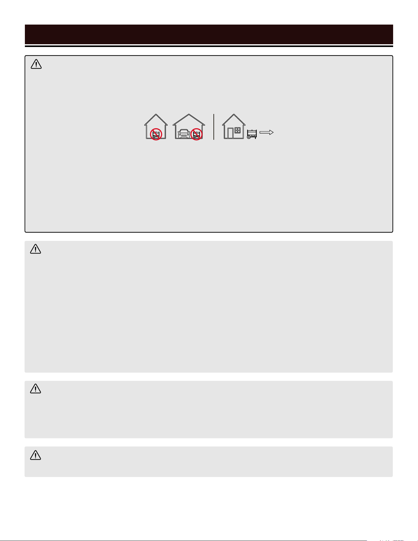
DANGER! CARBON MONOXIDE
Using a generator indoors CAN KILL YOU IN MINUTES. Generator exhaust contains carbon monoxide (CO). This
is a poison gas you cannot see or smell. If you can smell the generator exhaust, you are breathing CO. But even
if you cannot smell the exhaust, you could be breathing CO.
NEVER use a generator inside homes, garages, crawl spaces, or other partially enclosed areas. Deadly levels
of carbon monoxide can build up in these areas. Using a fan or opening windows and doors does NOT supply
enough fresh air. ONLY use a generator outside and far away from windows, doors, and vents. These openings
can pull in generator exhaust.
Even if you use a generator correctly, CO may leak into the home. ALWAYS use a battery-powered or battery-
backup CO alarm in the home. If you start to feel sick, dizzy, or weak after the generator has been running, move
to fresh air RIGHT AWAY. See a doctor. You may have carbon monoxide poisoning.
WARNING! RISK OF EXPLOSION. HIGHLY FLAMMABLE: This generator may emit highly flammable and
explosive gasoline vapors, which can cause severe burns or even death, if ignited. A nearby open flame can lead
to explosion even if not directly in contact with gasoline.
• Do not operate near open flame, heat, or any other ignition source. Do not smoke near the generator.
• Always operate on a firm, level surface.
• Always turn generator off before refueling. Allow generator to cool for at least 2 minutes before removing
fuel cap. Loosen cap slowly to relieve pressure in tank.
• Do not overfill fuel tank. Gasoline may expand during operation. Do not fill to the top of the tank. Allow for
expansion. Always check for spilled fuel before operating.
• If fuel spills, move the generator at least 30 feet away from the spill and wipe clean any spilled fuel before
starting the engine.
• Empty fuel tank before storing or transporting the generator.
WARNING! If this generator is used as a supply for a building’s wiring system, the generator must be in-
stalled by a qualified electrician and connected to a transfer switch as a separately derived system in accordance
with all applicable laws and electrical codes and the National Electrical Code, NFPA 70. The generator shall be
connected to a transfer switch that switches all conductors excluding the equipment grounding conductor. The
frame of the generator shall be connected to an approved grounding electrode.
CALIFORNIA PROPOSITION 65 WARNING: This product contains chemicals and produces exhaust known
to the State of California to cause cancer, birth defects and other reproductive harm.
6
7
GENERATOR SAFETY WARNINGS
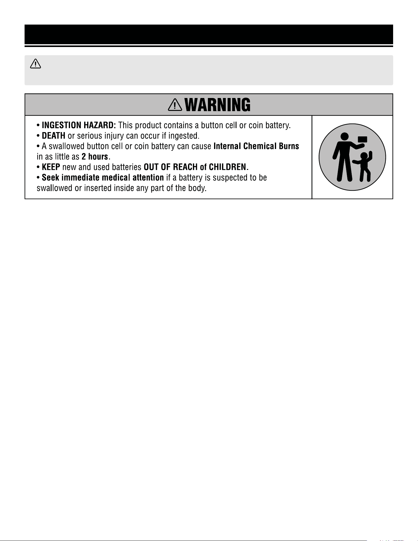
BUTTON OR COIN CELL BATTERY SAFETY
INFORMATION
PLEASE READ THE FOLLOWING CAREFULLY:
1. Remove and immediately recycle or dispose of used
batteries according to local regulations and keep away
from children. Do NOT dispose of batteries in household
trash or incinerate.
2. Even used batteries may cause severe injury or death.
3. Call a local poison control center for treatment infor-
mation.
4. The compatible battery type is CR2016 and the nomi-
nal battery voltage is 3V.
5. Non-rechargeable batteries are not to be recharged.
6. Do not force discharge, recharge, disassemble, heat
above 158ºF, or incinerate. Doing so may result in injury
due to venting, leakage or explosion resulting in chemi-
cal burns.
FOR REPLACEABLE BUTTON OR COIN CELL BATTER-
IES, PLEASE READ THE FOLLOWING CAREFULLY:
1. Ensure the batteries are installed correctly according
to polarity (+ and -).
2. Do not mix old and new batteries, different brands
or types of batteries, such as alkaline, carbon-zinc, or
rechargeable batteries.
3. Remove and immediately recycle or dispose of batter-
ies from equipment not used for an extended period of
time according to local regulations.
4. Always completely secure the battery compartment. If
the battery compartment does not close securely, stop
using the product, remove the batteries, and keep them
away from children.
OPERATING ENVIRONMENT
1. Using a generator indoors can kill you in minutes.
Only use a generator outside and far away from win-
dows, doors and vents.
2. Do not smoke near the generator.
3. Do not operate near open flame, heat, or flammable
materials. This generator may emit highly flammable
and explosive gasoline vapors, which can cause severe
burns or even death if ignited. A nearby open flame can
lead to an explosion even if it isn’t directly in contact with
gasoline.
4. Do not expose the generator to rainy or wet con-
ditions; doing so significantly increases the risk of
electrical shock. Never handle the generator, electronic
devices, or any cord while standing in water, while bare-
foot, or when hands or feet are wet.
5. Always operate the generator on a dry, firm, level
surface.
6. The generator should have at least 5 feet of clear-
ance from buildings or other equipment during opera-
tion.
7. Do not allow children or non-qualified persons to
operate the generator.
WARNING! Do not let comfort or familiarity with the product replace strict adherence to product safety rules.
Failure to follow the safety instructions may result in serious personal injury.

8
GENERATOR SAFETY WARNINGS
WARNING! Do not let comfort or familiarity with the product replace strict adherence to product safety rules.
Failure to follow the safety instructions may result in serious personal injury.
TO MAXIMIZE THE LIFESPAN OF YOUR GENERATOR: We recommend running your generator at least once a
month for 20 to 30 minutes. Start the generator according to the instructions and plug a small load in to make
sure the outlet is producing electricity. If you do not run it often, it will greatly shorten the generator’s lifespan
and void the warranty.
GENERATOR PREPARATION
1. Always ground the generator before using it to maxi-
mize safety (see “Ground the Generator” section).
2. Do not overfill fuel tank, as gasoline may expand
during operation. Do not fill to the very top of the tank.
Leave room for gasoline expansion. Always check for
spilled fuel before operating.
3. If any part of the generator, electrical device or pow-
er cord is broken, damaged, or defective, make sure
it is repaired or replaced before operation. Service
should only be performed by a qualified technician. Do
not use receptacles or cords that show signs of damage,
such as broken or cracked insulation.
4. Use a ground fault circuit interrupter (GFCI) in highly
conductive areas such as metal decking or steel work.
Extension cords with in-line GFCIs are recommended for
these operations to maximize safety.
5. If connecting the generator to a building’s electri-
cal system for standby power, you MUST consult a
qualified electrician and install a transfer switch. Such
connections must comply with local electrical laws and
codes. Failure to comply can create a back-feed, which
may result in serious injury or death to utility workers.
6. Never modify the generator in any way. Modifying
or using the machine for any other purpose for which it
is not designed may result in serious injuries, machine
damage and voiding of the warranty.
GENERATOR OPERATION
1. Only use the generator for its intended purposes.
Modifying or using the generator for operations for
which it was not designed may cause hazards and per-
sonal injury.
2. Do not touch bare wires or receptacles (outlets).
3. Do not turn on electrical devices until after they are
connected to the generator.
4. Do not exceed the wattage capacity of the generator
by plugging in more electrical devices than the unit
can handle. This could damage the generator and/or
connected electrical devices. Check the operating volt-
age and frequency requirements of all electrical devices
prior to plugging them into the generator.
5. Allow generator to run for several minutes before
connecting electrical devices. Do not start or stop en-
gine with electrical devices plugged in to the receptacles.
Failure to do so could damage the generator and/or con-
nected electrical devices.
6. Generators vibrate in normal use. During and after
the use of the generator, inspect both the generator as
well as extension and power supply cords for damage
resulting from vibration.
7. Do not touch hot parts. This generator produces heat
when running. Temperatures near exhaust can exceed
150ºF (65ºC). Allow generator to cool down after use be-
fore touching engine or areas of the generator that be-
come hot during use.
8. Turn off all connected electrical devices before stop-
ping the generator.
9. Always turn generator off before refueling. Allow
generator to cool for at least 2 minutes before removing
fuel cap. Loosen cap slowly to relieve pressure in tank.
10. Turn the engine switch and fuel selector knob to
“OFF” position when the engine is not running.
11. Empty fuel tank before storing or transporting the
generator. Do not store generator or gasoline near fur-
naces, water heaters, or any other appliances that pro-
duce heat or have automatic ignitions. Store the genera-
tor and fuel away from sparks, open flames, pilot lights,
heat and other sources of ignition.
12. Always wash hands after handling generator.
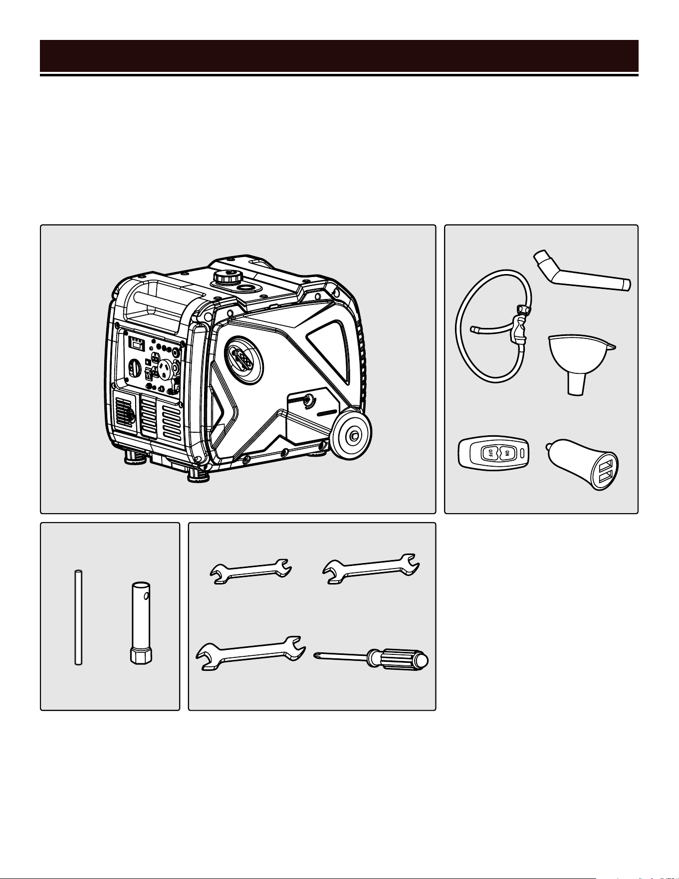
Components
Assembly Tools
Spark Arrestor Tools
Accessories
UNPACKING
With the help of a friend or trustworthy foe, such as one of your in-laws, carefully remove the generator from the
packaging and place it on a sturdy, flat surface. Make sure to take out all contents and accessories. Do not discard
the packaging until everything is removed. Check the packing list below to make sure you have all of the parts and
accessories. If any part is missing or broken, please contact customer service at 1-847-429-9263 (M-F 8-5 CST),
or email [email protected].
PACKING LIST
UNPACKING & PACKING LIST
WrenchHandle
9
Screwdriver
14mm / 17mm
Wrench
19mm Wrench
8mm / 10mm
Wrench
Generator
Funnel Cup
Funnel Tube
12V-USB Adapter
Regulator
Hose Assembly
Remote
100%
50%
0%
100%
50%
0%
VOLTAGE FREQUENCY TIME
FUELLOAD
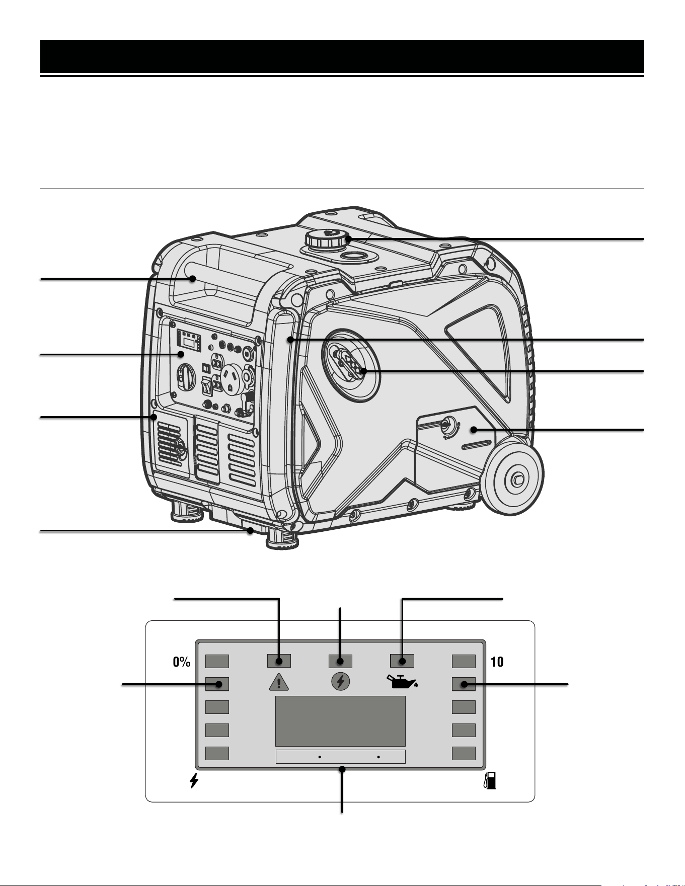
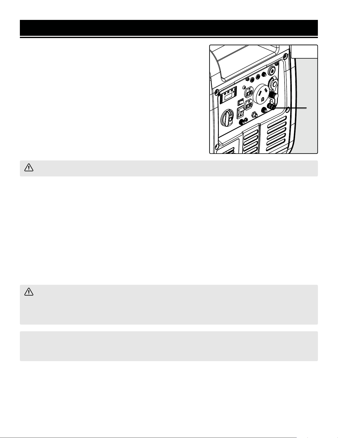
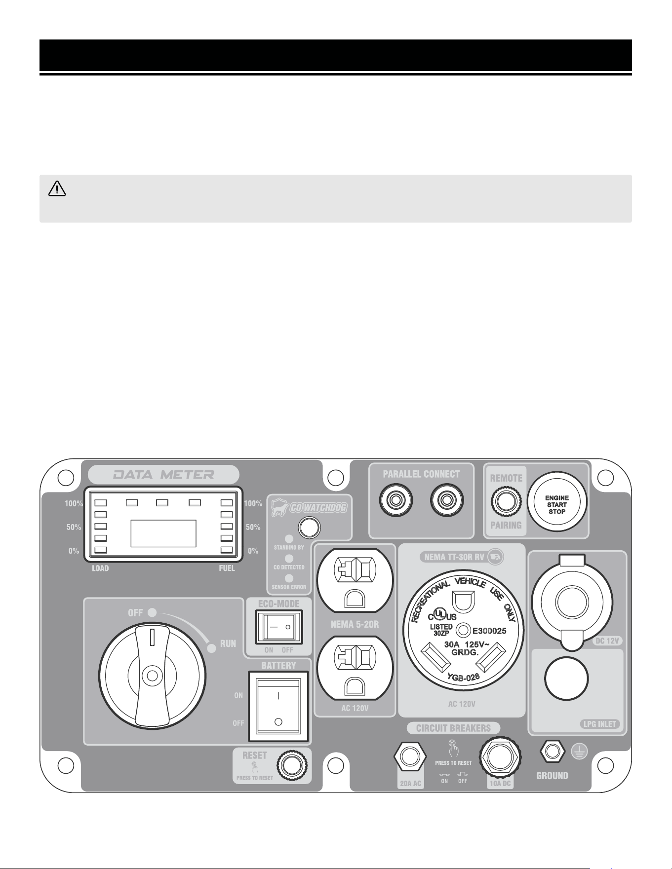
KNOW YOUR INVERTER GENERATOR
TOOL PURPOSE
Inverter Generators provide you with clean and quiet power, when and where you need it most. Refer to the fol-
lowing diagrams to become familiarized with all the parts and controls of your Generator. The components will be
referred to later in the manual for assembly and operation instructions.
GENERATOR
Fuel Cap
Carrying Handle
Control Panel
Battery Access
Transport Handle
Recoil Start
Oil Access Cover
Ventilation Slots
Overload Indicator (Red)
Output Indicator
(Green) Low Oil Indicator (Yellow)
Fuel IndicatorLoad Indicator
Digital Display
(Voltage, Frequency, Run Time, Maintenance Alert at 50 hours)
10
KNOW YOUR INVERTER GENERATOR
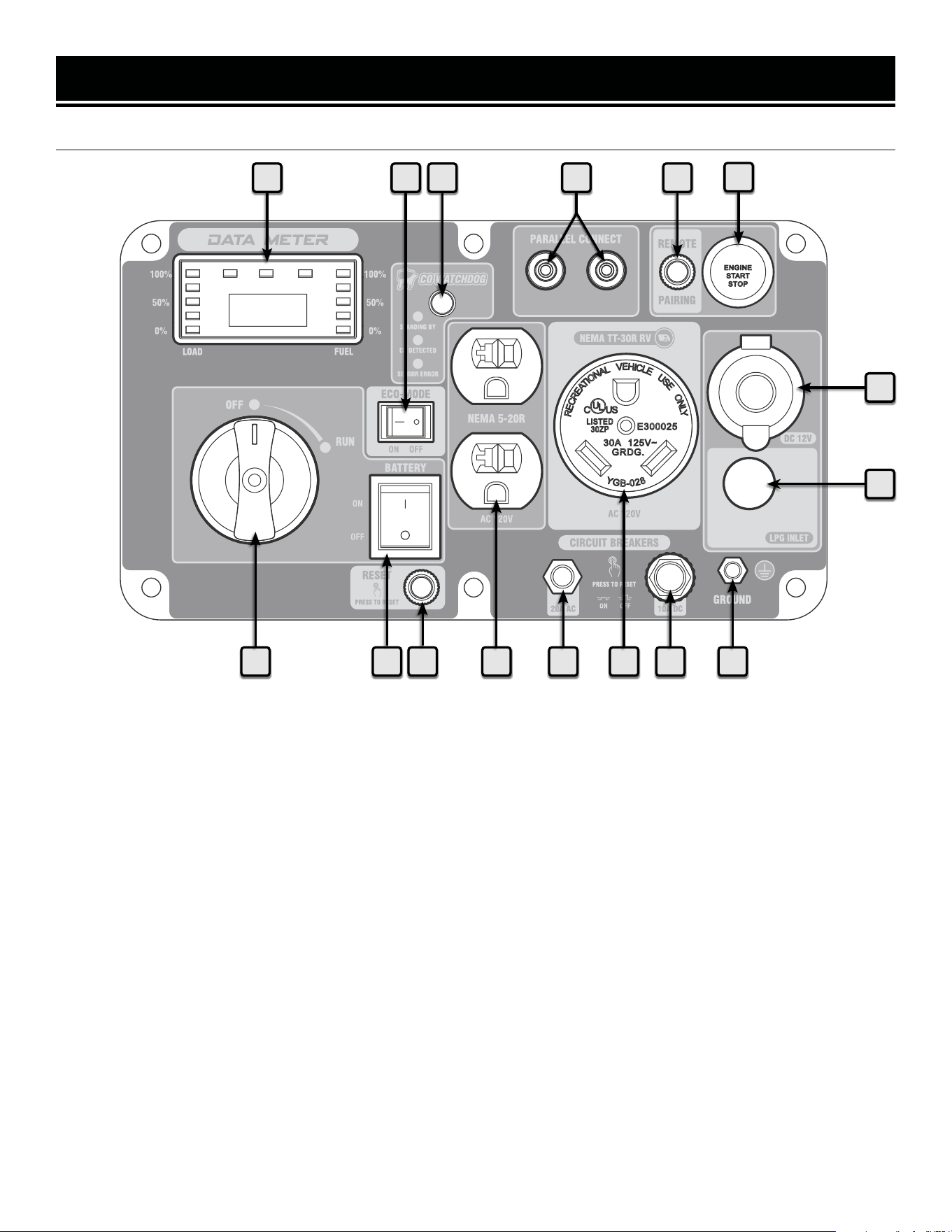
CONTROL PANEL
1 3
6
7
89101213
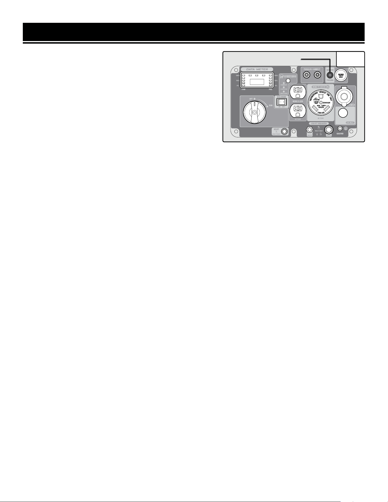
1. Data Meter with Indicator Light
2. Eco-Mode Switch
Turn ON to increase fuel economy and runtime when the
load is below 2625W.
3. Parallel Connection Port
Connect two WEN inverter generators through a parallel
connection kit for a higher output.
4. Remote Pairing Button
Use this button to pair the remote and generator. See
"REMOTE START" section (pages 22 - 23).
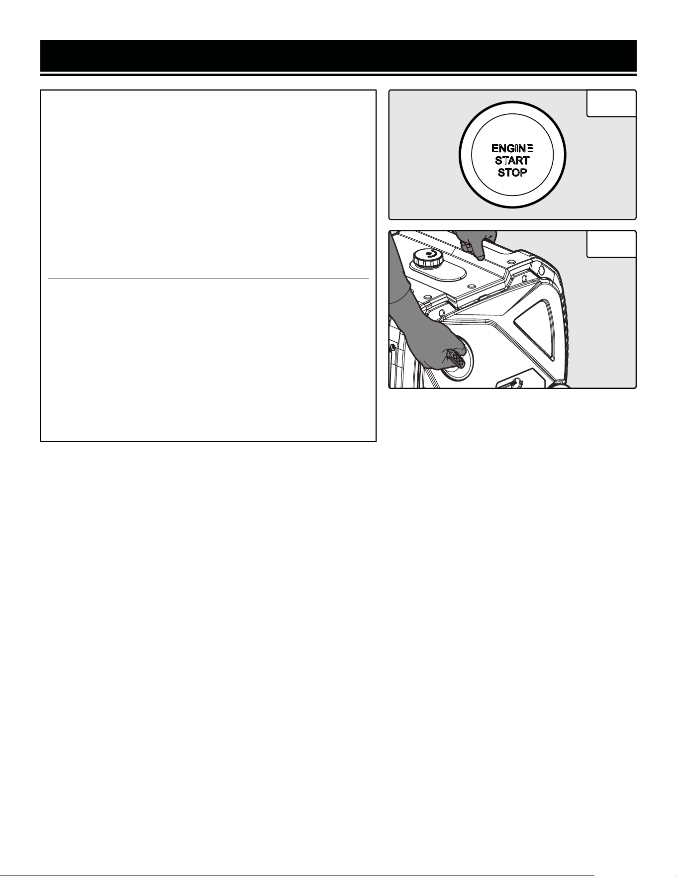
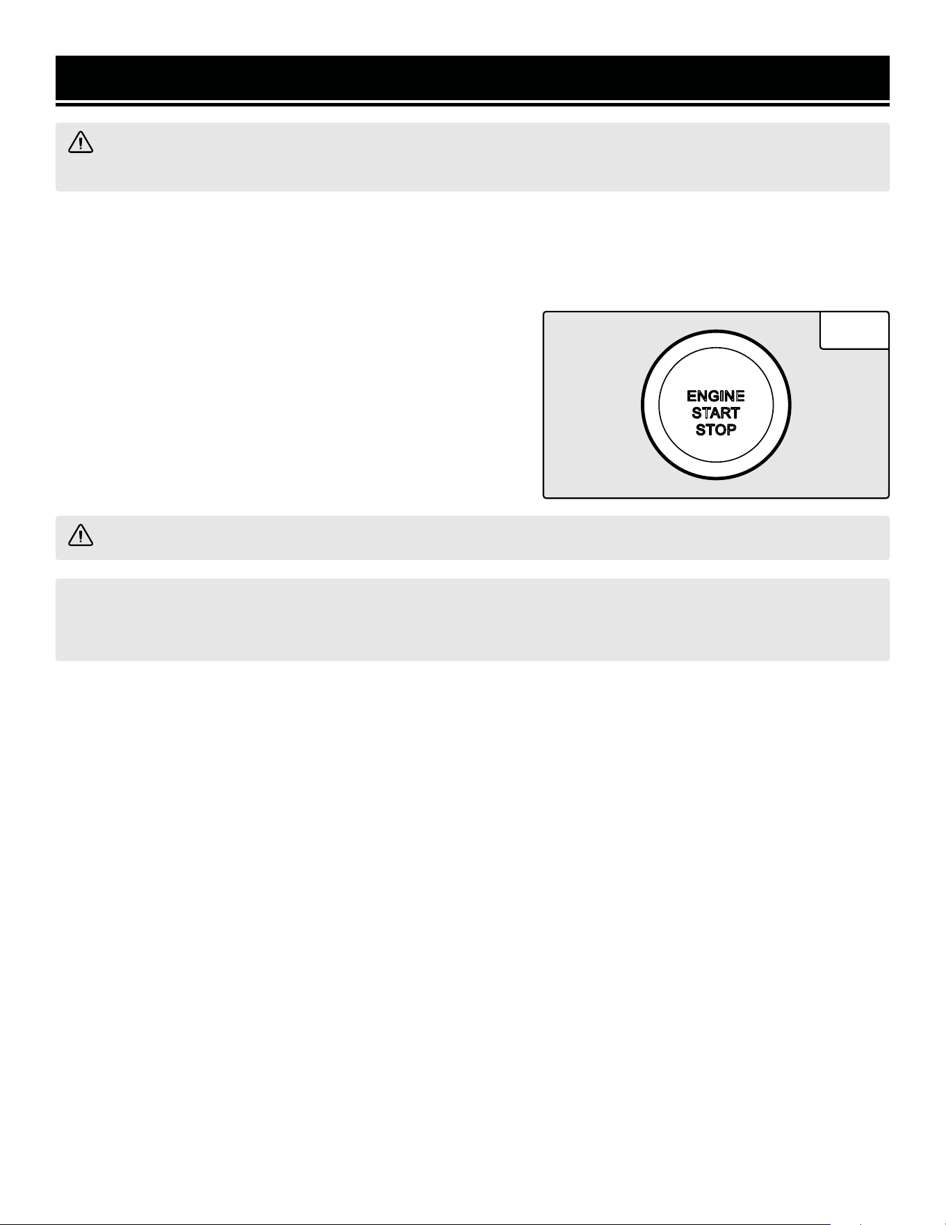
5. Engine Start / Stop Button
Use this button to start or stop the generator. The button
will also flash different colors to provide important infor-
mation about your generator. See "Starting Your Genera-
tor" (p. 20) and "Shutting Off Your Generator" (p. 33).
6. DC 12V Cigarette-Lighter Style Receptacle
7. LPG Inlet
8. Grounding Nut
Ground generator to reduce risk of electric shock.
11
2 4
5
11
9. DC Circuit Breaker (10A)
10. AC 120V NEMA TT-30 RV Receptacle
11. AC Circuit Breaker (20A)
12. AC 120V NEMA 5-20R Receptacles
13. Overload Reset
If the overload light is ON, press this button to reset.
14. Battery Switch
Control whether or not the battery is connected to the
control panel. Always turn battery switch OFF to con-
serve power after shutting down generator. You can also
shut down generator by turning the battery switch OFF.
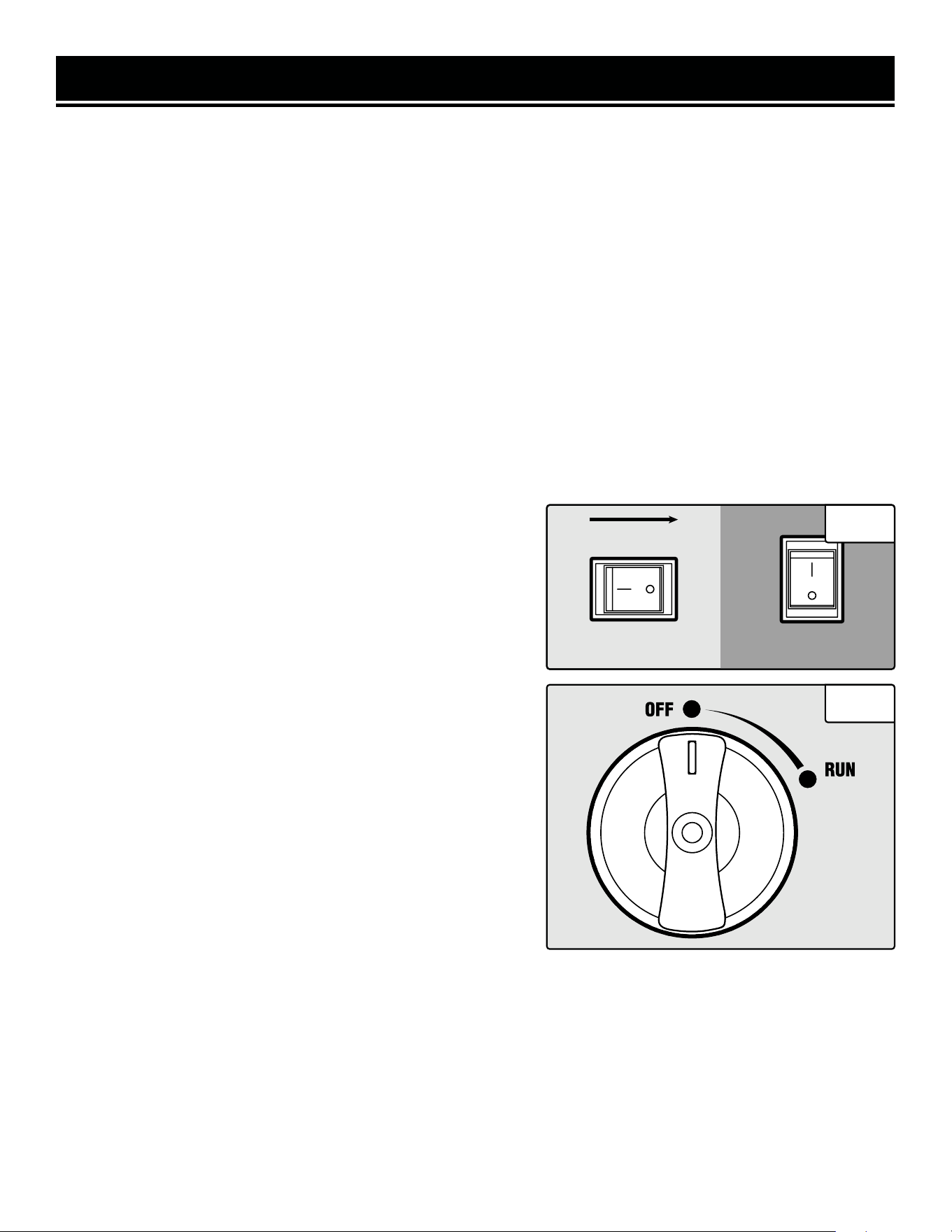
15. 2-in-1 Switch
Turn switch to run or automatically shut off generator.
16. CO WATCHDOG Carbon Monoxide Monitor
Measures the accumulation of poisonous CO gas while
the generator is running. If the level of CO gas gets too
high, the CO Watchdog system will automatically shut
down the generator.
15
16
14
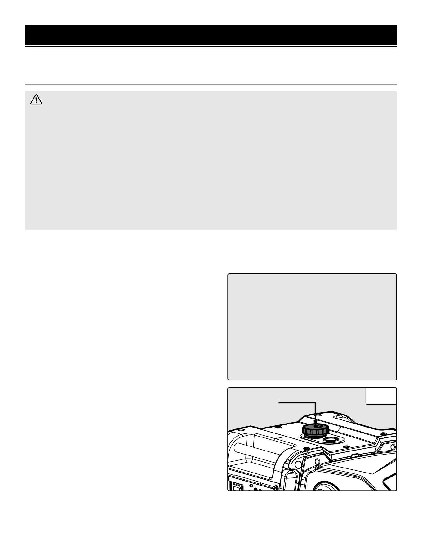
GENERATOR PREPARATION
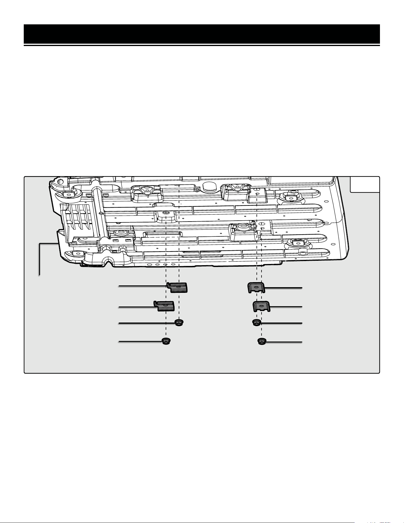
REMOVING THE MOUNTING PLATES
Your generator is shipped with four mounting plates that secure the engine to the generator housing in order to
prevent machine damage during shipping. Make sure to remove the four mounting plates before operating your
generator. Failure to do so could lead to engine damage.
To remove the mounting plates:
1. With the help of another person, place generator on an elevated platform such as table or workbench. Make sure
the generator is stable. Do not tilt the generator as there may be remaining oil inside the crankcase from testing.
2. Remove the four nuts (Fig. 1 - 3) and mounting plates (Fig. 1 - 2) from the generator's baseplate (Fig. 1 - 1).
3. Follow the instructions in the following pages to prepare your generator for starting.
Fig. 1
1
2
2
3
3
2
2
3
3
12
Synthetic 5W-30
30W
10W-30
GENERATOR PREPARATION
The following section describes the necessary steps to prepare the generator for use. If you are unsure about how
to perform any of the steps, please call 1-847-429-9263 M-F 8-5 CST for customer service. Failure to perform these
steps properly can damage the generator or shorten its life.
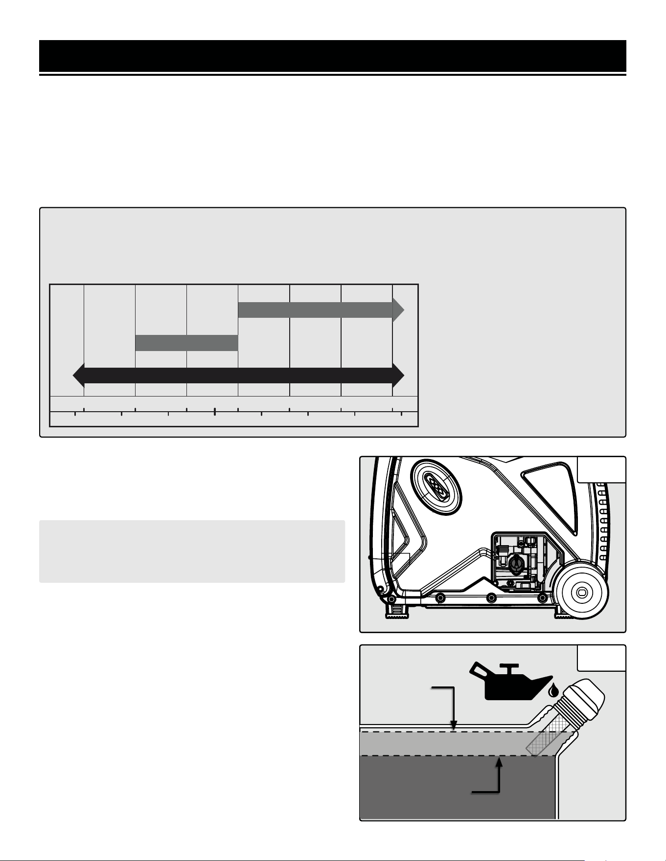
STEP 1 - ADD / CHECK OIL
The generator is shipped without oil. User must add the proper amount of oil before operating the generator for the
first time. The oil capacity of the engine crankcase is 18.6 fl. oz. (0.55 L).
• 30W Engine Oil
Temperatures above 40°F
• 10W-30 Engine Oil
Temperatures between 0°F - 40°F
• Synthetic 5W-30 Engine Oil
All temperature ranges
ENGINE OIL RECOMMENDATIONS
Select good quality detergent oil bearing the American Petroleum Institute (API) service classifications
SJ, SL, or SM (synthetic oils may be used). Select the SAE viscosity grade of oil that matches the
expected operating temperature.
°F
°C
-20 0 20 32 40 60 80 100
40200
-20
-10
10
-30 30
To add oil, follow these steps:
1. Place the generator on a level surface. Make sure the en-
gine is off before adding or checking oil.
CAUTION: Keep the generator level! Tilting the generator
to assist in filling will cause oil to flow into the wrong
areas of the engine and cause damage.
2. Turn the oil access cover knob to the unlocked position,
and remove the access cover from the side panel. Unscrew
the oil dipstick from the engine (Fig. 2).
3. Using an oil funnel or appropriate dispenser, slowly add
oil into the oil fill, being careful not to overfill the unit. Fill the
crankcase to the upper fill line so you can visually see the oil
coming halfway up the oil fill threads (Fig. 3).
4. Reinstall the oil dipstick and firmly tighten it. Wipe clean
any spilled oil.
5. Reinstall the oil access cover. Turn the oil access cover
knob to the locked position to secure the cover in place.
Fig. 2
Upper Level
Fill Line
Lower LevelLower Level
Fill LineFill Line
Lower Level
Fill Line
13
Fig. 3
100%
50%
0%
100%
50%
0%
FUELLOAD
VOLTAGE FREQUENCY TIME
GENERATOR PREPARATION
STEP 1 - ADD / CHECK OIL (CONTINUED)
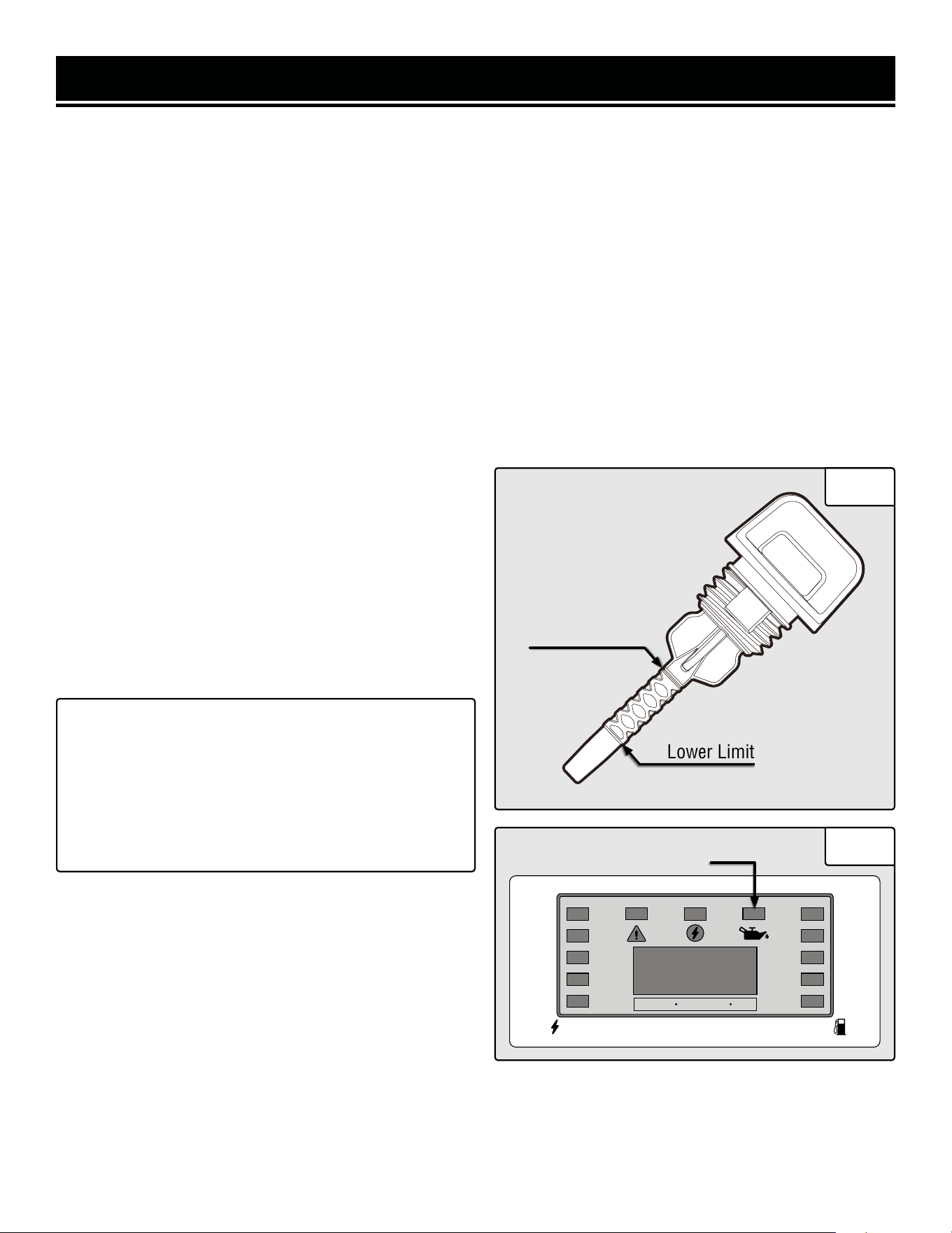
For subsequent operation, the oil level should be checked before each use, or after every 8 hours of operation. The
generator is equipped with a low-oil sensor and will not start without a sufficient amount of oil.
To check oil level (before every subsequent start):
1. Place the generator on a level surface. Make sure the engine is off before adding or checking oil.
2. Open the oil access cover. Remove and wipe the dipstick with a clean rag.
3. Insert the dipstick into the oil fill without screwing it in. Remove the dipstick to check the oil mark (Fig. 4).
If the oil mark covers less than one half of the dipstick, slowly add oil until the oil mark reaches to the top of the
dipstick (or when you can see the oil coming halfway up the oil fill threads).
4. Wipe clean any oil leaks and firmly tighten the dipstick. Reinstall the oil access cover.
OIL LEVEL SHUTDOWN
To protect the unit from damage, the generator is equipped
with a low-oil-pressure shutoff that will automatically stop
the engine when the oil level is too low. The yellow low oil
indication light (Fig. 5) will turn ON to remind you that the
engine oil level is low and need to be refilled.
The oil level of the engine should be checked before each
start to ensure that the engine crankcase contains suf-
ficient lubricant.
TIP: Your WEN generator is compatible with the WEN
55201 Magnetic Oil Dipstick (not included), available
for purchase at wenproducts.com. The dipstick’s in-
dustrial-strength magnetic tip will collect metal shav-
ings from your generator’s oil compartment to help
preserve the engine and extend your generator’s lifes-
pan.
Lower Limit
Upper Limit
Low Oil Indicator
Fig. 4
Fig. 5
14
GENERATOR PREPARATION
WARNING! RISK OF EXPLOSION. HIGHLY FLAMMABLE: This generator may emit highly flammable and
explosive gasoline vapors, which can cause severe burns or even death, if ignited. A nearby open flame can lead
to explosion even if not directly in contact with gasoline.
• Do not operate near open flame, heat, or any other ignition source. Do not smoke near the generator.
• Always operate on a firm, level surface.
• Always turn generator off before refueling. Allow generator to cool for at least 2 minutes before removing
fuel cap. Loosen cap slowly to relieve pressure in tank.
• Do not overfill fuel tank. Gasoline may expand during operation. Do not fill to the top of the tank. Allow for
expansion. Always check for spilled fuel before operating.
• If fuel spills, move the generator at least 30 feet away from the spill and wipe clean any spilled fuel before
starting the engine.
• Empty fuel tank before storing or transporting the generator.
STEP 2 - ADD / CHECK FUEL
Use ONLY fresh (within 30 days from purchase), lead-free gasoline with a minimum of 87 octane rating. The genera-
tor performs best with ethanol-free gasoline. DO NOT use gasoline with over 10% ethanol. The capacity of the fuel
tank is 2.2 US gallons (8.50 L). Do not mix oil with gasoline.
To add gasoline:
1. Make sure the generator is shut OFF and on a level sur-
face. Unscrew the fuel cap (Fig. 6) and set it aside. The fuel
cap may be tight and hard to unscrew.
2. Slowly add unleaded gasoline to the fuel tank. Be careful
not to overfill.
NOTE: Do not fill the fuel tank to the very top. If you do so,
gasoline will expand and spill during use, even with the fuel
cap in place.
3. Reinstall fuel cap and wipe clean any spilled gasoline with
a dry cloth.
To check fuel level:
During operation, the fuel level will be displayed by the in-
dicator lights on the right side of the multi-meter. If the fuel
level is low, refill the fuel tank before starting your generator
for the next time.
IMPORTANT:
• Avoid getting dirt or water into the fuel tank.
• Keep gasoline away from sparks, open flames,
pilot lights, heat, and other sources of ignition.
• Gasoline can age in the tank and make starting
difficult. Never store the generator for more
than 2 months with fuel in the tank.
• Never use an oil/gasoline mixture.
• Never use old gasoline.
Fig. 6
Fuel Cap
15
FUEL OPTION A: GASOLINE
GENERATOR PREPARATION
STEP 2 - ADD / CHECK FUEL (CONTINUED)
FUEL OPTION B: LIQUID PETROLEUM GAS (LPG)
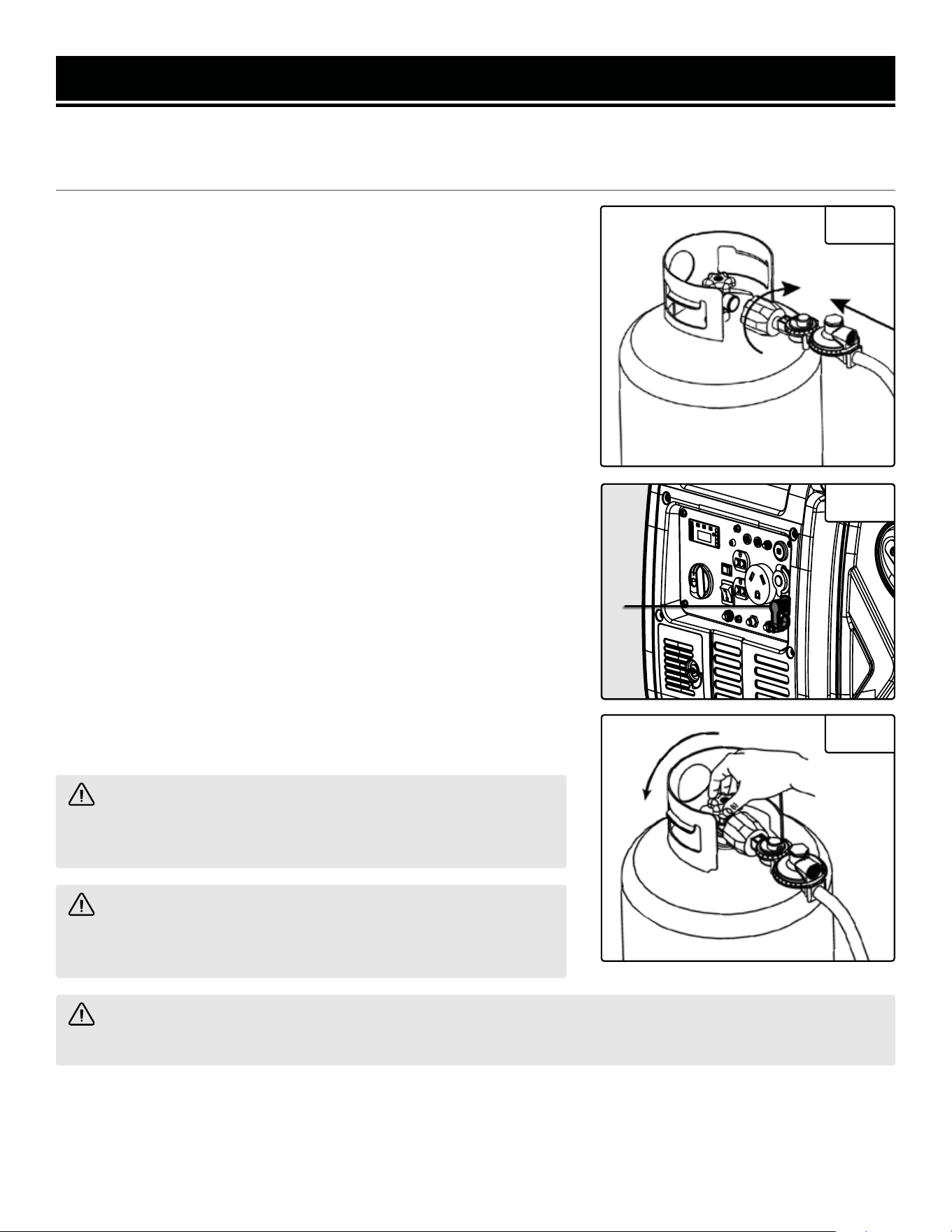
To connect your generator to an LPG cylinder:
1. Take off the safety caps from the cylinder valve, generator mounted
regulator, and regulator connecting hose ends.
2. With the LPG tank valve closed, attach the LPG regulator connecting
hose to the valve. Turn the plastic coupling from the hose right (clock-
wise) to tighten hose assembly onto the LPG tank (Fig. 7).
3. Remove the protective rubber cover from the LPG inlet (Fig. 8 -
1) on the generator panel. Connect the nut on the other end of the
regulator connecting hose to the LPG inlet. Tighten the nut using the
included 19mm wrench. Turn the 2-in-1 dial switch to OFF.
4. Turn the LPG tank valve ON (Fig. 9) and check for leaks by spraying
soapy water to check connections. If bubbles appear, become larger
in size, or increase in number, a leak exists. This MUST be corrected
before using generator. Contact WEN customer service at 1-847-429-
9263, M-F 8-5 CST, or email [email protected] for as-
sistance.
NOTE: You can use Teflon (or other tape) to secure the connection of
the LPG hose to your generator.
NOTE: If you would like to purchase other accessories for your dual-
fuel generator, consult your local dealer of propane and propane ac-
cessories, I tell you what.
CAUTION! Always position the LPG cylinder so the connection
between the tank and LPG inlet won’t cause sharp bends or kinks
in the hose.
WARNING! Risk of burns. Contact with liquid contents of cyl-
inder will cause freeze burns to the skin. If liquid contents contacts
skin or eyes, seek immediate medical attention.
WARNING! When transporting and storing, keep cylinder secured in an upright position with cylinder valve
turned off. Keep cylinders ventilated and away from heat when in a vehicle.
Fig. 7
Fig. 8
Fig. 9
1
16
AUTO FUEL SELECTION
Your generator is equipped with Auto Fuel Selection Technology. What this means is that the generator will auto-
matically select the fuel source (LPG or gasoline) depending on availability. LPG is prioritized; this means that if a
propane tank with enough LPG is connected, the generator will automatically use LPG. If no propane tank is con-
nected, or if there is no LPG remaining in the tank, the generator will use gasoline (if there is gasoline in the fuel
tank). Refer to Table 1 below for information on how to set up your generator for a particular fuel.
GENERATOR PREPARATION
Propane tank valve 2-in-1 dial on generator
I want to use gasoline. Closed Run
I want to use LPG. Open Run* or Off
Table 1 – Auto Fuel Selection® chart.*It is ideal to run the generator on LPG with the fuel valve closed (OFF), but if
it stays open (RUN), the generator will still run properly.
NOTE: Make sure the generator can handle the load(s) you plan to connect. The generator can provide more power
when running on gasoline than on LPG. Consult the specifications table on p. 3, as well as page 26 (“Calculating the
Wattage of Your Device(s)”) to ensure that your load(s) will not exceed the rated wattage for a particular fuel. See
also "Switching Fuels" (p. 29) for more information.
ABOUT THE BATTERY
1. The lithium-ion battery supplied with your generator is only partially charged, in order to maximize its service
life. The battery may not have enough charge to start the engine during its first use. If this is the case, connect the
battery according to the instructions below, and start the generator using the recoil starter, according to the instruc-
tions below. The battery will receive charge when the generator is running.
2. Lithium-ion batteries are subject to a natural aging process. The battery must be replaced at the latest when its
capacity falls to just 80% of its capacity when new. Weakened cells in an aged battery are no longer capable of meet-
ing the high power requirements needed for the proper operation of your generator, and therefore pose a safety risk.
3. DO NOT INCINERATE BATTERY. Do not throw the battery into an open fire as this poses a risk of explosion. Do
not ignite the battery or expose it to fire.
4. AVOID DAMAGE AND SHOCKS. Immediately replace batteries that have been dropped from a height of more than
one meter (3 feet) or those that have been exposed to violent shocks, even if the housing of the battery appears to
be undamaged. The battery cells inside the battery may have suffered serious damage. In such instances, please
read the waste disposal information on p. 38 for proper battery disposal.
5. DO NOT CRUSH, DROP OR DAMAGE BATTERY. Do not use the battery if it has sustained a sharp blow, been
dropped, run over or has been damaged in any way (e.g. pierced with a nail, hit with a hammer, stepped on, etc.).
6. DO NOT DISASSEMBLE. Incorrect reassembly may pose a serious risk of electric shock, fire or exposure to toxic
battery chemicals. If battery or charger are damaged, call WEN customer service at 1-847-429-9263 for assistance.
7. DO NOT SHORT CIRCUIT. Batteries will short circuit if a metal object makes a connection between the positive
and negative contacts on the battery. Do not place the battery near anything that may cause a short circuit, such as
paper clips, coins, keys, screws, nails and other metallic objects. A short-circuited battery poses a risk of fire and
severe personal injury. NOTE: The safe temperature range for charging the battery is 25°F – 104°F.
The generator is shipped with the lithium-ion battery’s quick-connectors disconnected to maximize safety. To start
the generator using electric start, the battery must be connected.
STEP 3 - CONNECT THE BATTERY
WARNING! Use only genuine WEN batteries with your generator (part no. 56380i-1304). Use of other bat-
teries may induce premature product failure and could pose a safety risk.
17
GENERATOR PREPARATION
STEP 3 - CONNECT THE BATTERY (CONTINUED)
WARNING! Use only genuine WEN batteries with your generator (part no. 56380i-1304). Use of other bat-
teries may induce premature product failure and could pose a safety risk.
Fig. 10
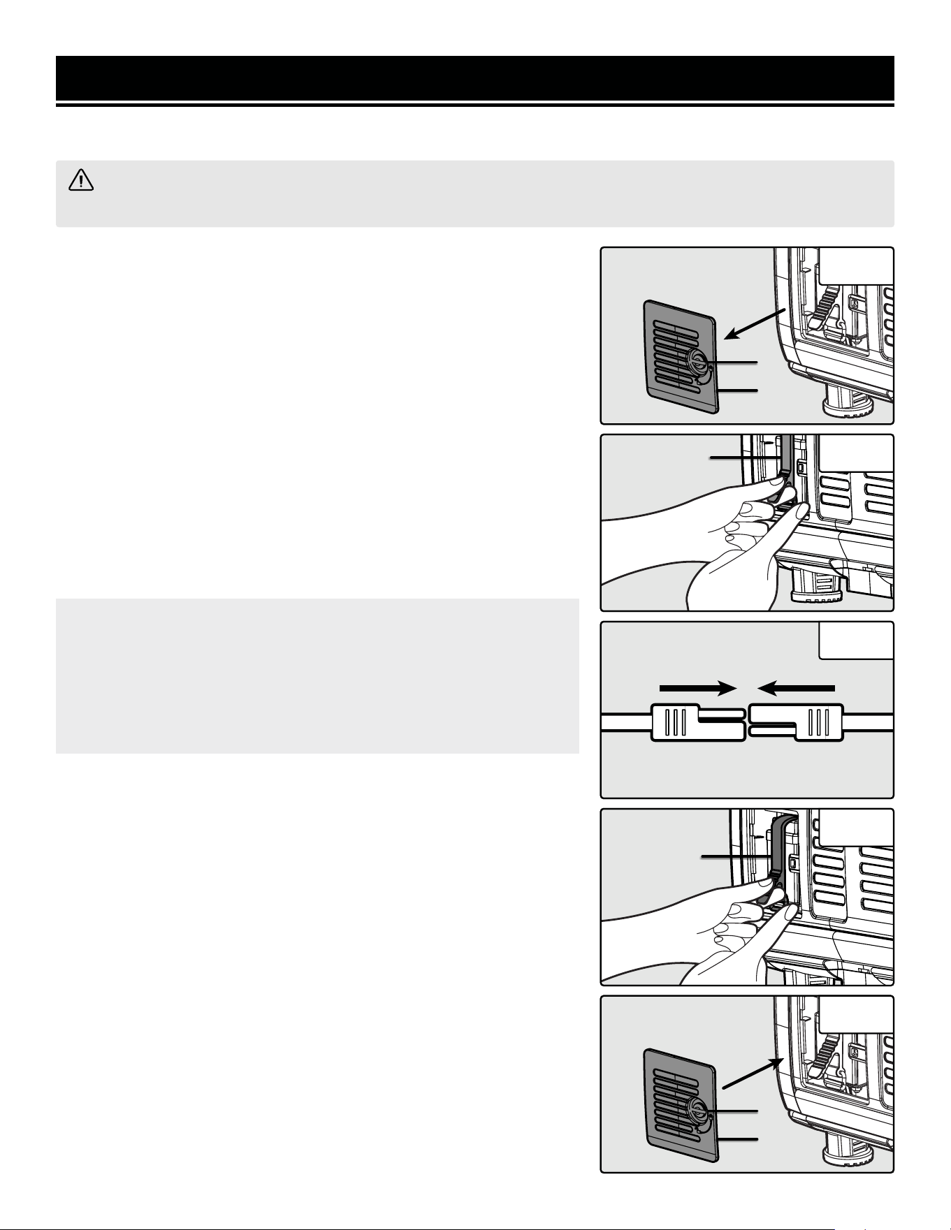
To connect the battery:
1. Using a coin or flat-head screwdriver (not included), turn the screw
(Fig. 10 - 1) on the battery access cover (Fig. 10 -2) and remove the
cover.
2. Pull downwards on the rubber belt (Fig. 11 - 1). With your other hand,
free the metal buckle from the hook beneath the battery.
3. Connect the two ends of the quick connector on the battery (Fig. 12)
to connect the battery to the generator’s system.
4. Slide the battery back into the generator. Pull downwards on the rub-
ber belt (Fig. 13 - 1). With your other hand, latch the metal buckle onto
the hook beneath the battery.
5. Reinstall the battery access cover (Fig. 14 - 1) using a coin or flat-
head screwdriver (not included) to turn the screw (Fig. 14 - 2).
1
2
Fig. 11
1
Fig. 12
Fig. 13
1
Fig. 14
2
1
18
IMPORTANT: If you do not plan to use the generator for a long
period of time, we recommend DISCONNECTING the quick-connec-
tors to protect the battery from losing charge. After disconnecting
the quick-connectors, cover the free end with an insulator such as
electrical tape. You may also choose to use a trickle charger (not
included) to maintain battery charge.
GENERATOR PREPARATION
STEP 4 - GROUND THE GENERATOR
To reduce the risk of electric shock and to maximize safety, the genera-
tor should be properly grounded.
Ground the generator by tightening the grounding nut (Fig. 15 - 1) on
the front control panel against a grounding wire. A generally acceptable
grounding wire is a No. 12 AWG (American Wire Gauge) stranded cop-
per wire.
This grounding wire should be connected at the other end to a copper,
brass, or steel grounding rod that is driven into the earth. Wire and
grounding rods are not included with the generator.
NOTE: Grounding codes can vary by location. Contact a local electri-
cian to check the area codes.
WARNING! Failure to properly ground the generator increases your risk of electric shock.
HIGH ALTITUDE OPERATION ABOVE 3000 FEET
The fuel system on this generator may be affected by operation at high altitudes. Proper operation can be ensured by
installing an altitude kit at altitudes higher than 3000 feet above sea level. At elevations above 8000 feet, the engine
may experience a decrease in performance, even with the proper altitude kit. Operating this generator without said
kit may increase the engine’s emissions and decrease both fuel economy and performance.
You can order the kit at wenproducts.com by searching part DF400i-HA. There are two kits - one for altitudes be-
tween 3000 and 6000 feet (part no. DF400i-HA36), and the other for altitudes from 6000 to 8000 feet (part no.
DF400i-HA68). This kit should be installed by a qualified mechanic. Refer to the instructions included with your
altitude kit for more information about installation.
NOTE: The high altitude kit must be installed for operation above 3000 feet, regardless of the fuel source (LPG or
gasoline) used.
WARNING! To prevent serious injury from fire, follow the kit installation procedures in a well-ventilated
area away from ignition sources. If the engine is hot from use, shut the engine off and wait for it to cool before
proceeding. Do not smoke near the generator. Warranty will be void if adjustments are not made for high altitude
use.
CAUTION: Engines with the high-altitude kit installed operated at lower altitudes could cause severe engine dam-
age and affect emissions compliance. Be sure to uninstall the high altitude kit when operating at altitudes below
3000 feet.
After completing the above preparation, the generator is ready to be started.
1
Fig. 15
19
CAUTION!
Disconnect all electrical loads from the generator before attempting to start.
Before starting the generator, make sure you have read and performed the steps in the “Generator Preparation”
section of this manual. If you are unsure about how to perform any of the steps in this manual please call 1-847-
429-9263 M-F 8-5 CST for customer service.
To maximize safety, ALWAYS ground the generator before using it. See section “Ground the Generator”.
Use a ground fault circuit interrupter (GFCI) in highly conductive areas such as metal decking or steel work. GFCIs
are available in-line with some extension cords.
STARTING YOUR GENERATOR
DANGER! CARBON MONOXIDE
Using a generator indoors CAN KILL YOU IN MINUTES. Generator exhaust contains carbon monoxide (CO). This
is a poison gas you cannot see or smell. If you can smell the generator exhaust, you are breathing CO. But even
if you cannot smell the exhaust, you could be breathing CO.
NEVER use a generator inside homes, garages, crawl spaces, or other partially enclosed areas. Deadly levels
of carbon monoxide can build up in these areas. Using a fan or opening windows and doors does NOT supply
enough fresh air. ONLY use a generator outside and far away from windows, doors, and vents. These openings
can pull in generator exhaust.
Even if you use a generator correctly, CO may leak into the home. ALWAYS use a battery-powered or battery-
backup CO alarm in the home. If you start to feel sick, dizzy, or weak after the generator has been running, move
to fresh air RIGHT AWAY. See a doctor. You may have carbon monoxide poisoning.
WARNING! The exhaust from this product contains chemicals known to the State of California to cause
cancer, birth defects, or other reproductive harm.
WARNING! Do not operate generator near open flame or flammable materials This generator may emit
highly flammable and explosive gasoline vapors, which can cause severe burns or even death if ignited. A
nearby open flame can lead to explosion even if it isn’t directly in contact with gasoline. Do not smoke near the
generator.
WARNING! This generator produces powerful voltage, which can result in electrocution.
WARNING! Do not use in rainy or wet conditions. Do not touch bare wires or receptacles (outlets). Do not
allow children or non-qualified persons to operate.
WARNING! Generator should only be connected to electrical devices, either directly or with an extension
cord. NEVER connect to a building electrical system without a qualified electrician and connected to a transfer
switch as a separately derived system. Such connections must comply with local electrical laws and codes.
Failure to comply can create a back-feed, which may result in serious injury or death to utility workers.
Follow the instructions on the next page to start your generator.
20
BATTERY
ON
OFF
STARTING YOUR GENERATOR
BEFORE STARTING THE GENERATOR
1. Verify that the generator is outside on a dry, level surface with at least two feet of clearance on all sides.
2. To maximize safety, check that the generator is properly grounded (see “Ground the Generator”).
3. Check that there is a sufficient level of oil in the crankcase. Add oil if necessary (see “Add/check Oil”).
4. If using gasoline, make sure there is enough gasoline in the fuel tank. Add fuel if necessary (see "Add/check Fuel").
If using LPG, make sure there is enough propane in the tank, and that the tank and regulator hose are connected.
5. Make sure all electrical devices are unplugged from the generator during ignition. Otherwise it will be difficult for
the engine to start.
STARTING THE GENERATOR (GASOLINE)
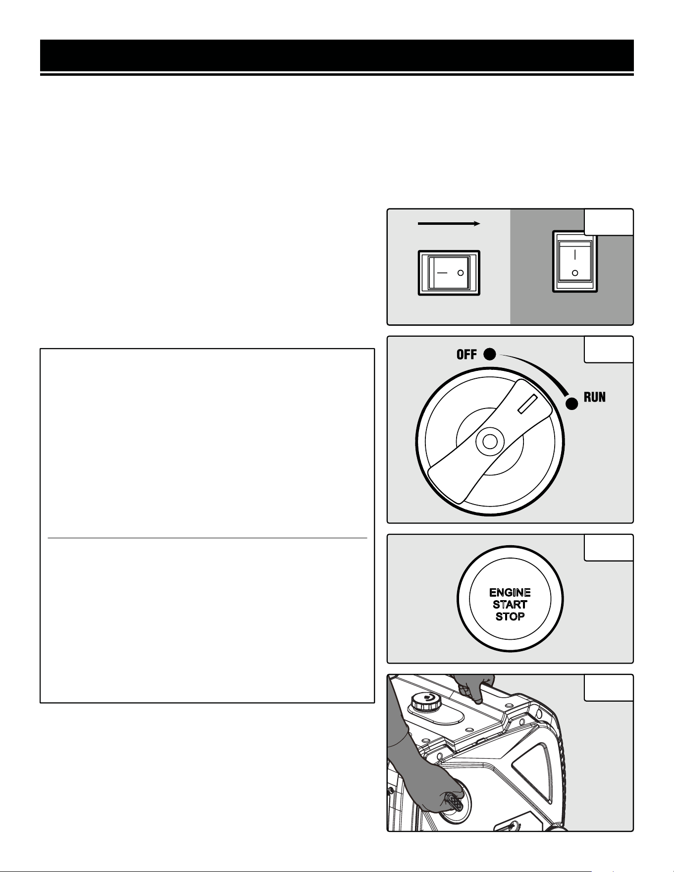
1. Turn the ECO-MODE switch (Fig. 16) to "OFF" during starting.
2. Turn the BATTERY switch (Fig. 16) to "ON".
NOTE: The battery switch must be turned ON when starting the
generator, regardless of the method or fuel source used.
3. Turn the 2-in-1 (Fig. 17) switch to the "RUN" position.
NOTE: If you have repeated failed attempts to start the engine,
please consult the troubleshooting guide. If problems persist,
please call please call 1-847-429-9263 M-F 8-5 CST.
6. Allow the generator to run for several minutes before attempt-
ing to connect any electrical devices. This allows the generator to
stabilize its speed and temperature.
Option A: Electric Start
3. Press the engine start / stop button (Fig. A) for one second.
NOTE: The engine start / stop button will begin flashing green,
and will automatically adjust the choke and start the engine.
NOTE: The generator will make 6 attempts to start the engine.
If after 6 attempts the engine has not started, the engine start
/ stop button will flash red for 30 seconds. Check the trouble-
shooting steps. If after checking all these steps the engine still
will not start, contact WEN customer service for assistance.
Option B: Pull Start
3. Pull the recoil starter handle slowly until a slight resistance
is felt, then pull quickly to start the engine. Return cord gently
into the recoil starter. Never allow the cord to snap back (Fig.
18).
NOTE: If the engine does not start after multiple attempts,
please consult the troubleshooting guide before attempting to
start the generator again. If problems persist, please contact
WEN customer service.
ON OFF
ECO-MODE
Fig. 16
21
Fig. 18
Fig. A
Fig. 17

USING THE REMOTE-START FUNCTION
Your generator comes with a remote-start function, enabling you to (what else?) start your generator remotely. Your
generator and the included remote have been paired at the factory, and you can use the remote immediately.
NOTE: In order for the remote start function to work properly, you must be within 98.43 ft (30 m) of the generator.
The remote’s effective range may vary depending on the battery's state of charge, as well as miscellaneous environ-
mental factors, radio interference, etc.
STARTING THE GENERATOR (REMOTE START)
1. Ensure that the battery switch on the panel is turned ON. Ensure that the battery is connected and is not dead.
Ensure that there is enough fuel, and the fuel selector switch is turned to the proper fuel source.
2. Ensure that all electrical devices are disconnected from the generator. Ensure that ECO-MODE is OFF.
3. Press the ON button on the remote control once. DO NOT hold the button down. The generator will wait for a
moment, then automatically adjust the choke and start.
NOTE: The generator will make 6 attempts to start the engine automatically. If after 6 attempts the engine has not
started, the engine start/stop button will flash red for 30 seconds. Check the troubleshooting steps. If after checking
all these steps the engine still will not start, contact WEN customer service for assistance.
4. Connect electrical devices.
NOTE: After the CO Watchdog system shuts down the generator, the generator cannot be restarted using remote
start, for safety reasons. You must manually restart the generator using the recoil or electric starter. After doing this,
the remote start can be used normally.
STOPPING THE GENERATOR (REMOTE START)
1. Turn off all electrical devices prior to unplugging them from the generator. Unplugging running devices can cause
damage to the generator. Never start or stop the generator with electrical devices plugged in or turned on.
2. Let engine run at no-load for several minutes to stabilize its internal temperature. Ensure that ECO-mode is OFF.
3. Press the OFF button on the remote control once. Do NOT hold the button down. The generator will then shut
down. The engine start/stop button will flash red and green simultaneously a few times to indicate that the generator
was shut down remotely.
4. Once the engine shuts down, if the battery switch is still set to ON, the generator will enter standby mode. In
standby mode, the generator can be started using the remote. The engine start/stop button will blink green once
every 2 seconds to remind you that the generator is in standby mode.
NOTE: There is no limit to how long the generator will stay in standby mode, so if you forget to turn off the battery
switch, it is possible that the battery will be drained the next time you try to use the generator. If you see the engine
start/stop switch flashing green, always make sure the battery switch is turned OFF.
NOTE: During remote start and remote start, you may see the data meter display flicker slightly. This is normal and
does not indicate a problem.
NOTE: If you purchase a new remote, you will need to pair the new remote with the generator. Follow instructions
below. When replacing batteries in a remote, you should not need to pair the generator and remote again, but if you
find that it does not work with new batteries, follow the instructions below to pair the generator and remote again.
STARTING YOUR GENERATOR
22
PAIRING THE REMOTE AND GENERATOR
1. Make sure the battery is connected and charged, and the bat-
tery switch on the panel is set to ON.
2. Press the remote pairing button (Fig. B - 1) on the control
panel once.
3. The engine start/stop button will flash red once.
4. Press the ON and OFF buttons on the remote simultaneously,
within 5 seconds after seeing the engine start/stop
button flash.
STARTING YOUR GENERATOR
5. The engine start/stop button will flash red 4 times.
6. The generator will enter standby mode, and the engine start/stop button will flash green every 2 seconds.
NOTE: If in step 4, the ON and OFF buttons are not pressed within 5 seconds, the generator will enter its standby
state. Start again from step 2 to pair the remote and generator.
UNPAIRING THE REMOTE AND GENERATOR
1. Make sure the battery is connected and charged, and the battery switch on the panel is set to ON.
2. Press the remote pairing button on the control panel 5 times quickly (within 5 seconds).
3. The engine start/stop button will flash red 4 times, and will clear all stored remote control data.
4. The generator will enter standby mode, and the engine start/stop button will flash green every 2 seconds.
REPLACING REMOTE BATTERIES
Your generator’s remote comes with two CR2016 batteries pre-installed and ready to use. However, the batteries will
eventually die and need to be replaced.
1. Use a fine-tipped Phillips-head screwdriver to remove the 3 screws on the back of the remote. Do not drop or lose
the screws. Open the back of the remote and remove the CR2016 batteries from the battery compartment.
2. Install the new CR2016 batteries in the same orientation as you removed the old batteries. (The + side, which
should say "CR2016", faces the back of the remote.)
3. Replace the back of the remote and tighten the screws. Follow the instructions above to pair your remote with the
generator (if necessary).
Fig. B1
23
BATTERY
ON
OFF
ON OFF
ECO-MODE
STARTING THE GENERATOR (LPG)
1. Turn the ECO-MODE switch (Fig. 19) to "OFF" during starting.
2. Turn the Battery switch (Fig. 19) to "ON".
NOTE: The battery switch must be turned ON when starting the
generator, regardless of the method or fuel source used.
3. Ensure that all electrical devices are disconnected from the
generator.
4. Make sure the propane regulator and hose are securely at-
tached to the propane cylinder and the propane inlet on the gen-
erator, and that the propane cylinder valve is turned ON.
5. Prime the engine by pulling the recoil starter 1 - 3 times.
6. Turn the 2-in-1 switch to OFF (Fig. 20).
Fig. 19
Fig. 20
STANDBY MODE
Once the generator is shut down, the generator’s remote control function will stay in standby mode while the battery
switch is ON. In standby mode, the generator can be started using the remote. The engine start/stop button will blink
green once every 2 seconds to remind you that the generator is in standby mode.
NOTE: There is no limit to how long the generator will stay in standby mode, so if you forget to turn off the battery
switch, it is possible that the battery will be drained the next time you try to use the generator. If you see the engine
start/stop switch flashing green, always make sure the battery switch is turned OFF.
PAIRING MULTIPLE REMOTES
You can pair up to 15 remotes at a time with your generator. Remotes can be purchased from wenproducts.com.
To pair a new remote with your generator, follow instructions above in “Pairing the Remote and the Generator”. You
can also pair one remote with as many generators as you like.
NOTE: If you have multiple remotes paired with your generator and you unpair one remote, you will also unpair
the other remotes simultaneously. You will need to pair the other remotes with the generator again before they can
be used. If at any point you have questions, problems, or concerns about the remote start function, consult the
Troubleshooting guide or contact customer service at 1-847-429-9263.
STARTING YOUR GENERATOR
24
STARTING YOUR GENERATOR
NOTE: If you have repeated failed attempts to start the engine, please consult the troubleshooting guide. If problems
persist, please call please call 1-847-429-9263 M-F 8-5 CST.
7. After the engine has started, the output indicator light (green) will light up.
8. Allow the generator to run for several minutes before attempting to connect any electrical devices. This allows the
generator to stabilize its speed and temperature.
ENGINE BREAK-IN PROCEDURE
The procedure below should be followed when you receive your generator in order to prolong the engine's service
life. This procedure helps to seat the piston rings properly in the cylinder, and will reduce overall wear on the engine.
For the first 8 hours of operation, vary the load, but keep it at or below 50% of the generator's rated wattage, if
possible. If your generator is equipped with an Eco-mode switch (only applicable for certain inverter generators),
engage Eco-mode periodically during the first 8 hours. After the first 8 hours, change the oil, then change it again af-
ter the first 25 hours. You may run the generator at full load after the 8-hour oil change. Refer to the Recommended
Maintenance Schedule in Table 5 for the full maintenance schedule.
Fig. 21
Option A: Electric Start
7. Press the engine start / stop button (Fig. C) for one second.
NOTE: The engine start/stop button will begin flashing green,
and will automatically adjust the choke and start the engine.
NOTE: The generator will make 6 attempts to start the engine.
If after 6 attempts the engine has not started, the engine start/
stop button will flash red for 30 seconds. Check the trouble-
shooting steps. If after checking all these steps the engine still
will not start, contact WEN customer service for assistance.
Option B: Pull Start
7. Pull the recoil starter handle slowly until a slight resistance
is felt, then pull quickly to start the engine. Return cord gently
into the recoil starter. Never allow the cord to snap back (Fig.
21).
NOTE: If the engine does not start after multiple attempts,
please consult the troubleshooting guide before attempting to
start the generator again. If problems persist, please contact
WEN customer service.
Fig. C
25
USING YOUR GENERATOR
CALCULATING THE WATTAGE OF YOUR DEVICE(S)
Connect electrical devices running on AC current according to their wattage requirements. Calculate the total run-
ning wattage and starting wattage of the device(s) you wish to connect, and MAKE SURE that they are within the
capacity of your generator and the capacity of each individual outlet.
Generator
Wattage
Capacity
GENERATOR RUNNING (RATED) WATTS GENERATOR STARTING (SURGE) WATTS
Gasoline: 3500W Gasoline: 4500W
LPG: 3150W LPG: 4050W
What this means:
The generator can produce a maximum of
3500W / 3150W on a continuous basis to
supply ongoing power to your electronic de-
vices.
NOTE: Also check the rated amperage for
each outlet and make sure not to overload
the individual outlets.
What this means:
Some devices such as box fans require short
bursts of extra power in addition to the rated
wattage listed by the device to start their mo-
tors.
The generator can produce a maximum watt-
age of 4500W / 4050W for a short period of
time (seconds) to cover the extra starting
power required by your electronic devices.
Electronic
Device
Wattage
Calculation
Find the wattage information of each device you plan to connect. The information should be
listed on the device or in its instruction manual, or you may refer to page 25, Table 2.
The wattage can be calculated using this equation: Watts = Volts x Amperes
To calculate the total running watts of your
devices:
+ Add up the running wattages of all the
device(s) you plan to connect.
= The total running (rated) wattage.
This wattage should NOT exceed the run-
ning wattage of 3500W / 3150W.
It is recommended to maintain a load at or
below 3150W / 2835W (90% of the rated
output) to ensure steady voltage output and
to prolong the generator’s lifespan.
To calculate the total starting watts of your
devices:
+ Add up the total running wattage of all the
device(s) you plan to connect.
+ Add the single highest ADDITIONAL start-
ing wattage out of the device(s) you plan to
connect.
= The total starting (surge) wattage.
This wattage should NOT exceed the starting
wattage of 4500W / 4050W.
If any of either of the total calculated running watts or starting watts is higher than the capac-
ity of your generator, adjust the load until both wattage requirements are met. Otherwise you
will overload the generator, and cause damage to the engine and your electrical device(s).
Table 1 - How to Calculate Wattages
26

USING YOUR GENERATOR
CALCULATING THE WATTAGE OF YOUR DEVICE(S) - CONTINUED
The chart below serves as a reference for the estimated wattage requirements of common electrical devices. How-
ever, do not solely rely on this chart - all electronics and appliances are built differently. Always check the wattage
listed on the electrical device before consulting this chart.
Tool or Appliance Rated (Running) Watts Surge (Starting) Watts
Electric Water Heater (40 Gal) 4000 0
Hot Plate 2500 0
Saw - Radial Arm 2000 2000
Electric Stove (Each Element) 1500-2800 0
Saw - Circular 1500 1500
Air Compressor (1 HP) 1500 3000
Window Air Conditioner 1200 1800
Saw - Miter 1200 1200
Microwave 1000 0
Well Water Pump 1000 1000
Sump Pump 800 1200
Refrigerator Freezer 800 1200
Furnace Blower 800 1300
Computer 800 0
Electric Drill 600 900
Television 500 0
Deep Freezer 500 500
Garage Door Opener 480 0
Stereo 400 0
Box Fan 300 600
Clock Radio 300 0
Security System 180 0
Dvd Player / VCR 100 0
Common Light Bulb 75 0
Table 2 - Estimated Wattages of Common Electrical Appliances
NOTE: Become familiar with the functions and capacity of each component on the control panel before con-
necting electrical devices. See page 23 for more information about the components of the control panel. Do not
overload generator or individual panel receptacles. Do not connect 50Hz or 3-phase loads to the generator.
27
USING YOUR GENERATOR
CONNECTING ELECTRICAL DEVICES
When the rated wattage requirement of each electrical device has been determined, add these numbers to find the
total rated wattage needed. If this number exceeds the rated wattage (3500 / 3150W) of the generator, DO NOT con-
nect all these devices. Select a combination of electrical devices with a total rated wattage lower than or equal to the
rated wattage of the generator.
CAUTION! Become familiar with the markings on the control panel before connecting electrical devices. Do
not connect 3-phase or 50Hz loads to the generator.
1. Before connecting electrical devices, allow the generator to run for a few minutes to stabilize the speed and volt-
age output.
2. Make sure that all devices are turned off. Start plugging in each electric device, from the highest wattage to the
lowest. Check the power indicator light (green) to ensure the generator is producing power.
3. Do not overload the generator or individual panel receptacles. If an overload occurs, the overload indication light
(red) will activate. If it is flashing, turn off and unplug one load. If it is solid (not flashing), the generator will cut
off power to protect itself. Unplug all electrical devices and then press the reset button to reset the entire circuit,
or press the circuit breaker to reset the DC circuit. Check the total wattage of the devices and reduce the load if it
exceeds the capacity of the generator. Then, plug the loads back in one by one.
NOTE: If the reset button or circuit breaker does not reset, wait several minutes and try again. If problem still per-
sists, please call 1-847-429-9263 M-F 8-5 CST, or email [email protected].
28
USING YOUR GENERATOR
Table 3 - Power Cord Requirement Guide
SOME NOTES ABOUT POWER CORDS
Long or thin cords can drain the power provided to an electrical device by the generator. When using such cords,
allow for a slightly higher rated wattage requirement by the electrical device.
*NR = Not Recommended
Device Requirements Max. Cord Length (ft) by Wire Gauge
Amps Watts
(120V)
Watts (240V) #8 wire #10 wire #12 wire #14 wire #16 wire
2.5 300 600 NR NR NR 375 250
5 600 1200 NR NR 300 200 125
7.5 900 1800 NR 350 200 125 100
10 1200 2400 NR 250 150 100 50
15 1800 3600 NR 150 100 65 NR
20 2400 4800 175 125 75 50 NR
25 3000 6000 150 100 60 NR NR
30 3600 7200 125 65 NR NR NR
40 4800 9600 90 NR NR NR NR
WARNING! Generator should only be connected to electrical devices, either directly or with an extension
cord. NEVER CONNECT TO A BUILDING ELECTRICAL SYSTEM without a qualified electrician and connected to
a transfer switch as a separately derived system. Such connections must comply with local electrical laws and
codes. Failure to comply can create a back-feed, which may result in serious injury or death to utility workers.
NOTE: For power outages, permanently installed, stationary generators are better suited for providing backup
power to your home. Even a properly connected portable generator can become overloaded. This may result in
overheating or stressing the machine’s components, possibly leading to generator failure.
SWITCHING FUELS
Your generator is equipped with Auto Fuel Selection technology. To maximize your generator's lifespan, we recom-
mend removing all loads from the generator before switching between gasoline and LPG. If this is not possible,
reduce loads as much as possible in order to ensure a smooth switch. Your generator is rated to handle a higher
load when running on gasoline than on LPG, so keep this in mind when planning your fuel usage.
29
USING YOUR GENERATOR
ECO-MODE SWITCH
This generator is equipped with an Eco-Mode Idle Control Switch
(Fig. 22). Engaging this switch allows the system to regulate the
engine speed and automatically adjust its fuel consumption to
match the required load. When the electrical load changes, the
generator engine will automatically speed up and slow down as
needed. This reduces fuel consumption and noise levels, while
extending runtime and engine’s lifespan.
Keep this switch engaged ONLY when the power load requirement is less than 2625W. Do not engage the Eco-Mode
Switch when the total load is more than 2625W. The generator engine must run at full speed to supply power for
anything over 2625W.
PARALLEL OPERATION
The parallel connection ports (Fig. 23) allow you to connect two
WEN generators to increase the total available electrical power.
The WEN Parallel Connection Kit can be purchased from
wenproducts.com. Follow the instructions included with your
parallel connection kit for proper installation and operation.
IN CASE OF OVERLOAD
If your generator becomes overloaded from too much drawn
wattage, the overload indicator (red) on the control panel will
light up. Follow the instructions below when an overload occurs:
• When you’re close to overloading the generator, the overload
light will start to flash. Reduce the load by turning off and dis-
connecting your electronic device(s) until the overload light turns
off. Then you may continue to operate your generator.
• When you’ve overloaded the generator, the overload light will stay on and the reset button (Fig. 24) will activate
to cut off the output in 3 to 16 seconds, depending on the load. Reduce the load by turning off and disconnecting
your electrical device(s) until the overload light turns off. Wait about five minutes and then press the activated reset
button to reset the circuit. If no power is produced after resetting, turn off and disconnect all electrical devices and
restart your generator.
Fig. 22
Fig. 23
Fig. 24
ON OFF
ECO-MODE
LIGHT
MEANING RESOLUTION
GREEN (POWER INDICATOR) RED (OVERLOAD)
ON OFF Generator output is normal. No action needed.
ON Flashing Continuously Generator is exceeding rated output. Reduce load on generator.
OFF
Flashes 1x
Repeating every 3 seconds
Voltage at alternator is too low.
No electrical output.
Check for loose connections.
Call 1-847-429-9263 for assistance.
OFF
Flashes 2x
Repeating every 3 seconds
Engine speed is too low.
No electrical output.
Check carburetor and stepper motor.
Ensure Eco-Mode is OFF. Have genera-
tor serviced; call 1-847-429-9263 for
assistance.
OFF
Flashes 3x
Repeating every 3 seconds
Inverter temperature is too high. No
electrical output.
Turn generator off and let cool down fully
(1-2 hours) before restarting.
OFF
Flashes 5x
Repeating every 3 seconds
Voltage at alternator is too high.
No electrical output.
Have generator serviced; call
1-847-429-9263 for assistance.
OFF
Flashes 6x
Repeating every 3 seconds
Generator has exceeded rated output
and cut off power to protect itself. No
electrical output.
Turn OFF and disconnect loads. Press
RESET button on panel. Reduce load on
generator.
30
USING YOUR GENERATOR
CIRCUIT BREAKERS
In addition to the reset button that protects the generator’s main
circuit, the circuit breakers (Fig. 25) protect the individual AC and
DC circuits. The 20-amp AC circuit breaker will activate when the
NEMA 5-20 outlets exceed 20A. The 10-amp DC circuit breaker
will activate when the DC 12V and USB outlets exceed 10A. When
the circuit breaker activates, turn off and disconnect the device
from its respective outlet, and press the circuit breaker to reset.
MULTI-METER
The multi-meter on your generator switches between voltage
Fig. 25
(e.g. 120.1), frequency (e.g. 60.0H), and runtime (e.g. 12.3) every 5 seconds. When you first use the generator, the
meter will count runtime, but will not store runtime until the generator is run for longer than 2 hours at a time. Once
the generator has been run for more than 2 hours at a time, the meter will track runtime normally. For an example,
as well as more explanation, please refer to Table 4 below.
SESSION NUMBER SESSION LENGTH
HOUR METER
AT END OF SESSION
DOES THE METER
RESET?
COMMENTS
1 1 hr 30 min 1.5 Yes, to 0.0
Meter will show “1.5” just before it is shut off,
but it has not been run for 2 hours at a time
yet.
2 30 min 0.5 Yes, to 0.0
Meter will show “0.5” just before it is shut off,
but it has not been run for 2 hours at a time
yet.
3 1 hr 1 Yes, to 0.0
Meter will show “1.0” just before it is shut off,
but it has not been run for 2 hours at a time
yet.
4 3 hr 3 No
Meter will show “3.0” at the end, since it has
been run for more than 2 hours. It will not in-
clude the 3 hours (1.5 + 0.5 + 1) the generator
was run before.
5 2 hr 5 No
Meter will show “5.0” at the end, since it has
been run for 3 + 2 = 5 hours. The meter is
counting normally, and will continue operating
normally.
Every 50 hours, the meter will display “]--[“, which is to remind you to perform 50-hour maintenance. Consult the
maintenance chart for recommended procedures. The display code will appear every 15 seconds for 6 minutes.
After 6 minutes, or after the generator is shut down and restarted, the code will clear and display voltage, frequency,
and runtime, as before.
NOTE: The fuel gauge on your multi-meter displays the amount of gasoline in the tank. It does not display the
amount of LPG remaining.
Table 4 - Meter Display
31

USING YOUR GENERATOR
CO SENSOR INFORMATION
The CO Watchdog carbon monoxide monitoring system (Fig.
26 - 1) measures the accumulation of poisonous CO gas
while the generator is running. If the level of CO gas gets too
high, the CO Watchdog system will automatically shut down
the generator. This system is not a substitute for an indoor
CO alarm.
Whenever the CO Watchdog system shuts down the genera-
tor, the LED on the generator control panel (Fig. 26 - 1) will
blink red for at least 5 minutes after the generator is shut
down. If you notice that the LED is blinking red, vacate the
area immediately. Go to an open, outdoor area. Ventilate
the area around the generator thoroughly before returning.
Let the generator stay shut down for a few minutes before
restarting the engine. This should allow carbon monoxide to
dissipate from the area. If you restart the generator and the
CO Watchdog detects that CO levels are still too high, it will
shut down the generator again. If CO levels are low enough,
the generator will run normally.
1
Ensure that the generator is located in an open outdoor area, with the exhaust pointing away from occupied struc-
tures, and pointing away from the prevailing winds, such that those winds do not blow engine exhaust towards the
sensor module. If anyone experiences dizziness, headaches, nausea, fatigue, or other symptoms of CO poisoning,
get to fresh air immediately and seek the attention of a qualified medical professional. Follow all other directions in
this manual regarding the connection and disconnection of electrical devices when starting or shutting down the
generator.
When starting the generator, the CO Watchdog LED on the panel may flash. This indicates that the system is running
a self-test procedure, and does not indicate a problem.
If the CO Watchdog LED on the panel is yellow, a system error has occurred, or the CO sensor has reached the end
of its life. Contact WEN customer service (1-847-429-9263, M – F 8 – 5 CST, or [email protected])
for assistance.
When operating your generator, please note the following:
• The CO Watchdog does not discriminate in its input; any source of carbon monoxide in the area around the genera-
tor could cause it to activate. If the CO Watchdog LED is blinking red, safety measures should be taken immediately.
• Tampering with, disconnecting, or bypassing the CO sensor could cause hazardous conditions, including but not
necessarily limited to injury or death, and will void your warranty. The generator will not run with the CO sensor
disconnected or bypassed, or if the CO sensor indicates an error.
• The CO sensor has a lifetime of about 7 years, and is capable of monitoring its lifetime. If your generator shows
an error light several years after purchase, it may be time to replace the CO sensor. Contact WEN customer service
for assistance.
NOTE: if the generator is oriented so that the
engine exhaust is blown towards the CO sensor,
the generator may shut down.
Fig. 26
32
SHUTTING OFF YOUR GENERATOR
CAUTION! Unplugging running devices can cause damage to the generator. Never stop the engine with elec-
trical devices connected and running.
OPTION 1A: AUTOMATIC FUEL SHUTOFF (RECOMMENDED – GASOLINE ONLY)
Your generator is equipped with automatic fuel shutoff. This feature turns off the flow of fuel, allowing for the gen-
erator to use up the remaining fuel from the carburetor before turning off. This prolongs the lifespan of the generator
by preventing build-up and blockages caused by stagnant fuel inside of a carburetor.
1. Turn off all electrical devices prior to unplugging them from
the generator. Unplugging running devices can cause damage to
the generator.
2. Allow generator to run at no load for a few minutes to stabilize
internal temperatures.
3. Turn the 2-in-1 switch to OFF (Fig. 27).
NOTE: The engine will continue to run until the majority of the
fuel in the carburetor is consumed, which takes a few minutes.
It will then shut off automatically. This feature helps to prevent
the carburetor from being clogged by stale fuel, extending your
generator’s lifespan.
4. Turn the BATTERY switch OFF (Fig. D).
OPTION 1B: AUTOMATIC FUEL SHUTOFF (RECOM-
MENDED – LPG ONLY)
Although LPG is not prone to degradation the way gasoline is, it
is still a good idea to turn the LPG tank OFF before disconnecting
the regulator hose from the generator, so that LPG does not leak
from the hose.
1. Turn off all electrical devices prior to unplugging them. Un-
plugging running devices can cause damage to generator.
2. Allow generator to run at no load for a few minutes to stabilize
internal temperatures.
3. Turn the 2-in-1 dial switch to the OFF position (Fig. 27), if it is
not in the OFF position already.
4. Turn propane tank valve to OFF position (if the propane regula-
tor hose is connected to the generator). The engine will continue
to run until propane in the carburetor is consumed, which will be
nearly immediately. It will then shut down automatically.
Fig. 27
Fig. 28
Fig. D
NOTE: If there is gasoline in the fuel tank, and any gasoline has made it into the carburetor for some reason, the
generator may continue to run for a few minutes until the gasoline has been consumed.
5. Turn the BATTERY switch OFF (Fig. D).
33
WARNING! Allow the generator to cool down before touching areas that become hot during use.
CAUTION: Allowing gasoline to sit in the fuel tank for long periods of time can make it difficult to start the gen-
erator in the future. Never store the generator for extended periods of time (over 2 months) with fuel in the fuel
tank. Refer to “Storing the Generator.”
SHUTTING OFF YOUR GENERATOR
CAUTION! Unplugging running devices can cause damage to the generator. Never stop the engine with elec-
trical devices connected and running.
OPTION 2: MANUAL SHUTOFF
In case you are in a hurry and do not want to wait for the generator to automatically shut down, the manual shutoff
feature is available. However, this method will leave stagnant fuel in the carburetor, possibly causing blockages,
a shortened lifespan, and other maintenance issues. If this approach is frequently taken, make sure to drain your
carburetor before any long storage periods.
1. Turn off all electrical devices prior to unplugging them from
the generator. Unplugging running devices can cause damage to
the generator.
2. Press the engine start / stop button (Fig. 29) once or press the
OFF button on the remote control once.
3. Turn the BATTERY switch OFF (Fig. D).
Fig. 29
34
MAINTENANCE
Proper routine maintenance of the generator will help prolong the life of the machine. Please perform maintenance
checks and operations according to the schedule in Table 4.
CAUTION! Never perform maintenance operations while the generator is running. Before maintaining or
servicing the generator, turn OFF the generator, disconnect all devices and allow the generator to cool down.
If there are any questions about the maintenance procedures listed in this manual, please call 1-847-429-9263 M-F
8-5 CST or email [email protected].
Recommended
Maintenance Schedule
Every 8
Hours or
Daily
Every 25
Hours
Every 3
Months or
50 Hours
Every 6
Months or
100 Hours
Before
Storage
As
Necessary
Engine Oil
Check Level x
Replace x** x** x* x
Air Filter
Check x*
Clean x*
Spark Plug
Check/Clean/
Regap
x
Change x x
Fuel
Check Level x
Drain x x
Carburetor Drain x x
Spark
Arrestor
Check/Clean x
Table 5 - Recommended Maintenance Schedule* Clean/change more often under dusty conditions or operating
under heavy load.
** Change the oil after the first 8 hours of operation, after the
first 25 hours of operation, and every 50 hours after that.
IMPORTANT GENERATOR MAINTENANCE TIPS:
• Drain your carburetor after each use and before storage to prevent it from clogging.
• Do not store the generator with fuel inside the tank for more than 2 months - the fuel will go bad.
• Run the generator for at least 20 minutes every month to charge the battery and maximize lifespan.
CLEANING THE GENERATOR
Keep the generator clean to prevent improper operation or machine damage from dirt and debris. Inspect all venti-
lation openings on the generator. These openings must be kept clean and unobstructed. If the generator becomes
dirty, use a damp cloth to wipe exterior surfaces. Use a soft bristle brush to loosen dirt and oil and use a vacuum to
pick up loose dirt. Use low pressure air (not to exceed 25 PSI) to blow away dirt.
CAUTION! Never clean the generator when it is running! Never clean with a bucket of water or a hose. Water
can get inside the working parts of the generator and cause corrosion or a short circuit.
NOTE: Failure to properly maintain the generator will void the warranty.
35
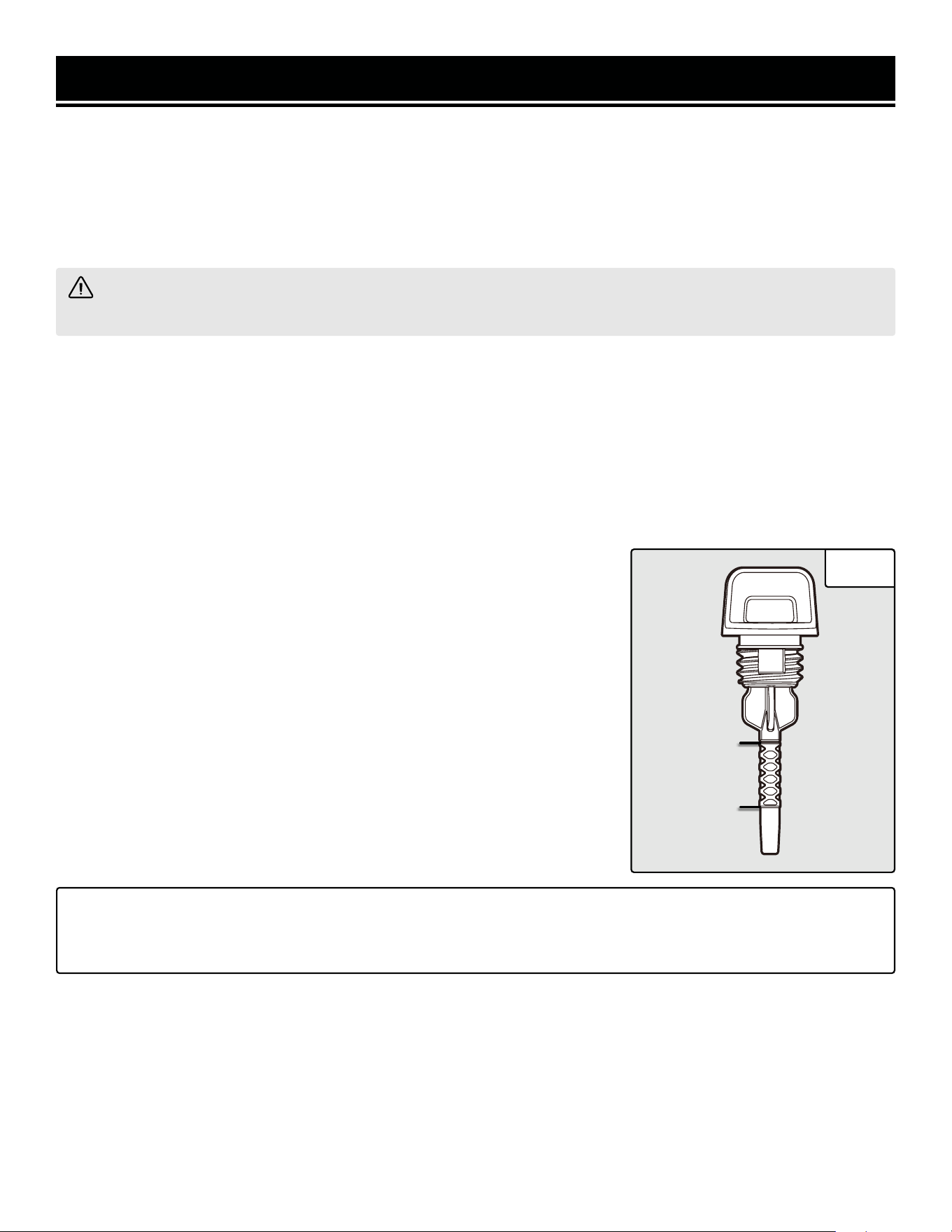
MAINTENANCE
CLEANING THE GENERATOR
Keep the generator clean to prevent improper operation or machine damage from dirt and debris. Inspect all ventila-
tion openings on the generator. These openings must be kept clean and unobstructed.
If the generator becomes dirty, use a damp cloth to wipe exterior surfaces. Use a soft bristle brush to loosen dirt and
oil and use a vacuum to pick up loose dirt. Use low pressure air (not to exceed 25 PSI) to blow away dirt.
WARNING! Never clean the generator when it is running! Never clean with a bucket of water or a hose. Water
can get inside the working parts of the generator and cause corrosion or a short circuit.
CHECKING / ADDING OIL
Check the oil level before each use and every 8 hours of operation (refer to Table 5).
The oil capacity of the generator engine is 18.6 fl. ounces. Add oil when the oil level is low. For proper type and
weight of oil refer to “add oil” portion of the “Generator Preparation” section. This is a critical step for proper engine
starting. The generator is equipped with a with low-oil shut down to protect it from running without oil.
To check the oil level and add oil:
1. Make sure the generator is on a level surface. Do not tilt the generator, as oil will flow into engine areas and cause
damage. Keep generator level!
2. Turn the oil access cover knob to the unlocked position, and remove the ac-
cess cover from the front panel. Clean around the oil fill. Remove the dipstick
and wipe it with a clean rag.
3. Insert the dipstick into the oil fill opening without screwing in. Remove the
dipstick to check the oil mark (Fig. 30). Add oil if the oil mark covers less than
one half of the dipstick.
4. Using a funnel or appropriate dispenser, slowly add more oil. Repeat the
step above until the oil mark reaches the top of the dipstick (you can see oil
coming up the threads of the oil fill). Do not over fill.
5. Reinstall dipstick and wipe clean any spilled oil with a rag. Reinstall the oil
access cover.
TIP: Your WEN generator is compatible with the WEN 55201 Magnetic Oil Dipstick (not included), available for
purchase at wenproducts.com. The dipstick’s industrial-strength magnetic tip will collect metal shavings from
your generator’s oil pan to help preserve the engine and extend your generator’s lifespan.
Upper Limit
Lower Limit
Fig. 30
36
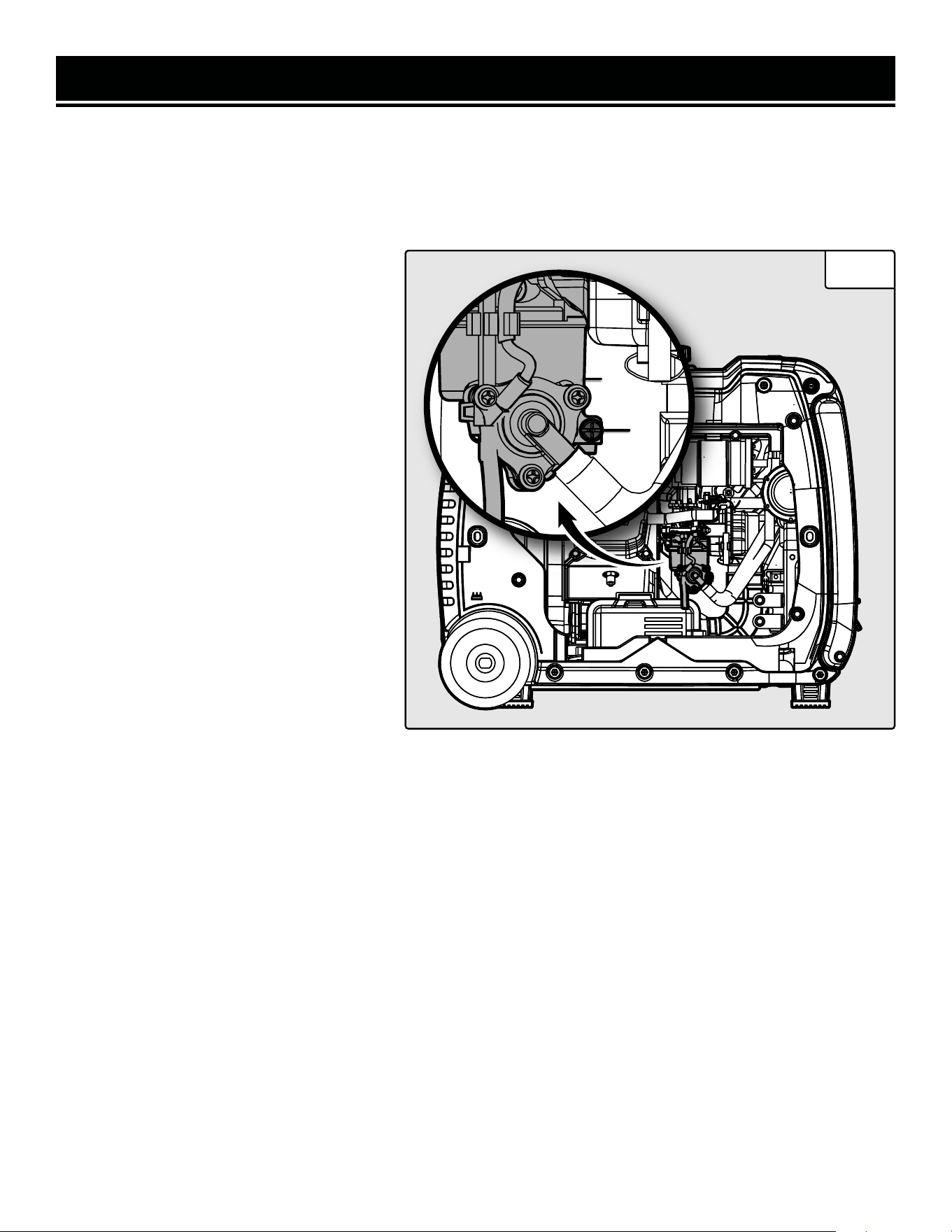
MAINTENANCE
DRAINING THE CARBURETOR
We recommend draining the carburetor after every use and before storing the generator. (If the generator is shut off
using the AUTO OFF feature, it is only necessary to drain it before periods of long storage.) Draining the carburetor
can prevent the fuel from clogging up the carburetor; a clogged carburetor can prevent the generator from starting.
1. With the help of another person, place the
generator on an elevated platform such as a
table or desk.
2. Make sure that the 2-in-1 dial switch to
turned to “OFF”. At this position, the fuel
valve is turned OFF so that only the fuel left
inside the carburetor will be drained out.
3. Using a Phillips-head screwdriver, unscrew
the top two screws and remove the service
panel on the opposite side of the recoil starter.
4. The carburetor (Fig. 31 - 1) can be ac-
cessed between the engine and the air filter.
Locate the transparent tube from the carbure-
tor that extends down through the base plate
of the generator.
5. Prepare an approved gasoline-storage con-
tainer and direct the end of the drain tube into
the container.
Fig. 31
6. Open up the carburetor drain screw (Fig. 31 - 2) with a Phillips-head screwdriver and drain out any gasoline that
has built up inside the carburetor through the drain tube into the approved gasoline-storage container.
7. Once the fuel has drained, tighten the drain screw with the screwdriver.
NOTE: Make sure to drain your carburetor before storing the generator for long periods of time.
8. Reinstall the service panel.
1
2
37
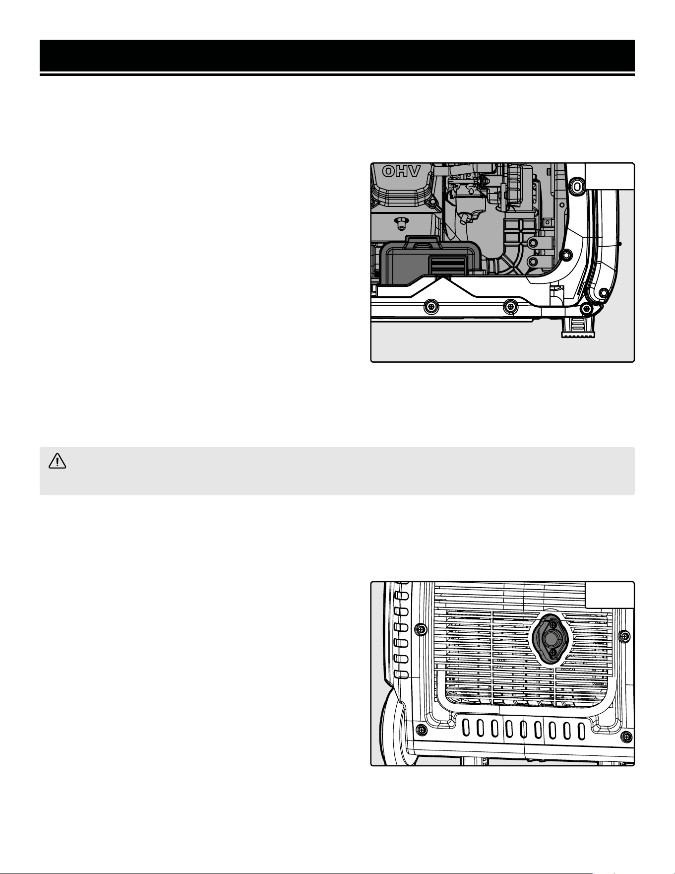
MAINTENANCE
AIR FILTER MAINTENANCE
Check every 50 hours of operation (refer to Table 5 - Recommended Maintenance Schedule).
Routine maintenance of the air filter helps maintain proper airflow to the carburetor. Occasionally check that the air
cleaner is free of excessive dirt.
To inspect and clean the air filter:
1. Using a Phillips-head screwdriver, unscrew the top two
screws and remove the service panel on the opposite side of
the recoil starter.
2. Take the cover off of the air filter (Fig. 32). Remove the
sponge-like air filter element from the casing. Wipe excessive
oil and any dirt from inside of the air filter casing.
3. Check and clean the foam air filter element. Good elements
can be washed in soapy water. Dry the element in clean cloth
(do not twist it). Add a few drops of engine oil to the air filter
element and spread it evenly.
If the air filter element has been damaged, replace it with a new one. Replacement air filters can be ordered from
wenproducts.com by searching part no. 56380i-1001B.1.
4. Reinstall the air filter element, air filter cover and service panel.
WARNING! Running the engine with a dirty, damaged or missing air filter element can result in danger to the
operator and cause the engine to wear out prematurely.
SPARK ARRESTOR MAINTENANCE
Inspect and clean the spark arrestor every 100 hours of operation.
The spark arrester is located outside the muffler, which gets very hot during operation. Allow the engine to cool
completely before servicing the spark arrester. To inspect and clean the spark arrester:
1. Remove the two Phillips-head screws that secure the
spark arrestor to the muffler (Fig. 33).
2. Remove the spark arrestor screen.
3. Carefully clean and remove the carbon deposits from the
spark arrestor screen with a wire brush. Replace the spark
arrestor if it is damaged (replacement spark arrestors can be
purchased from wenproducts.com by searching the part no.
56380i-1115).
4. Reinstall the spark arrestor in the muffler and secure it in
place with the screws.
Fig. 32
Fig. 33
Air Filter CoverAir Filter CoverAir Filter Cover
38
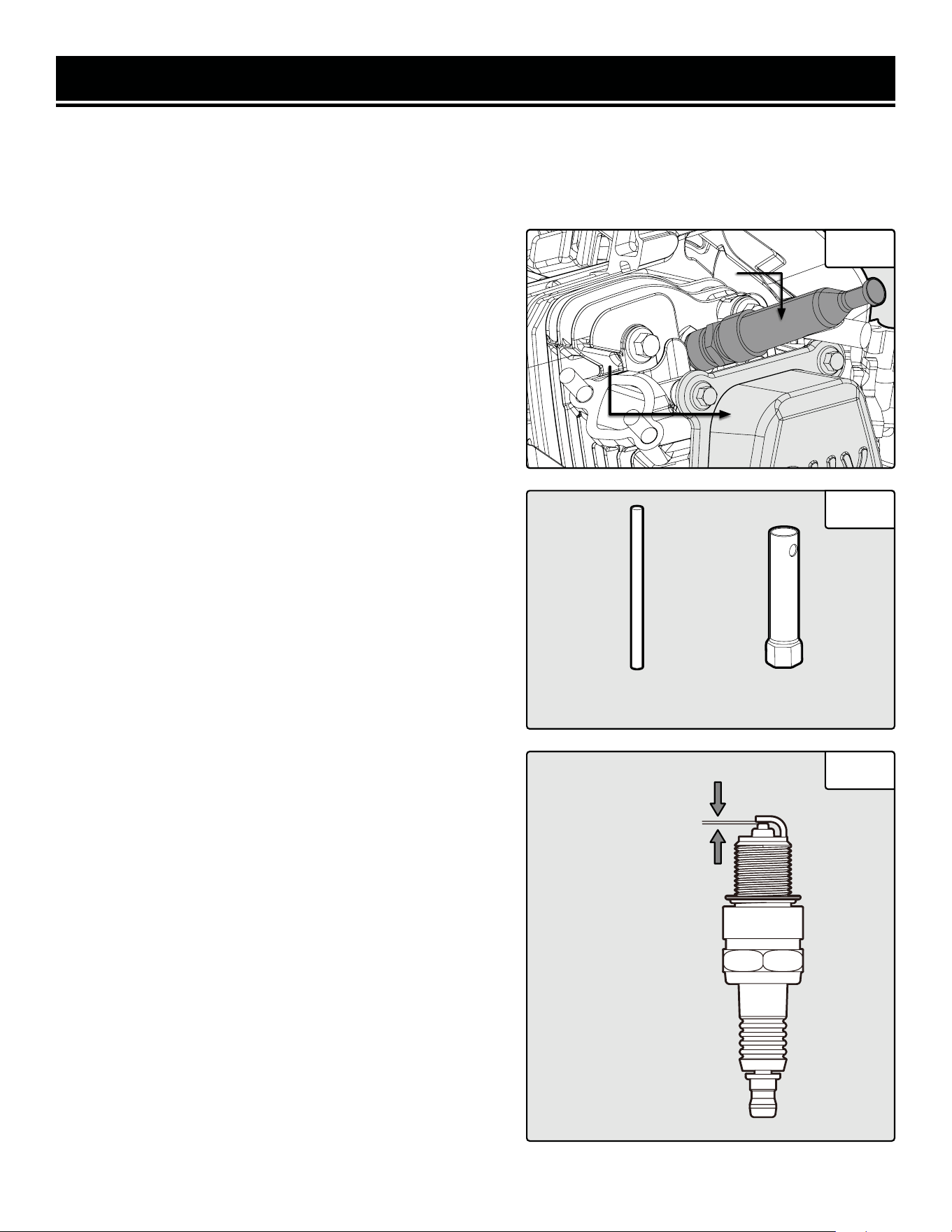
MAINTENANCE
SPARK PLUG MAINTENANCE
Refer to Recommended Maintenance Schedule in Table 5 for maintaining the spark plug.
The spark plug is important for proper engine operation. Check the spark plug regularly to maintain proper engine
operation. A good spark plug should be intact, free of deposits, and properly gapped.
To inspect or replace the spark plug:
1. Using a Phillips-head screwdriver, unscrew the top two
screws and remove the service panel on the opposite side of
the recoil starter.
2. Gently pull on the spark plug boot (Fig. 34) to remove it. Be
careful not to tear any insulation or wire.
3. Use the included spark plug wrench to unscrew and then
carefully remove the spark plug from the engine (Fig. 35).
TIP: There is limited space for the wrench to turn. Use both
rows of holes in the spark plug wrench to gain leverage to
loosen the plug.
4. Visually inspect the spark plug. If it is cracked or chipped,
or if the electrodes are worn or burned, discard it and replace
with a new spark plug.
We recommend replacing with a NGK BPR6ES/Torch F6RTC
spark plug (part no. 56310i-0104), available for purchase at
wenproducts.com.
5. If re-using the spark plug, use a wire brush to clean any dirt
from around the spark plug base, then re-gap the spark plug.
6. Measure the plug gap with a spark plug gap gauge. The gap
should be 0.7 - 0.8 mm (0.028 - 0.031 in) (Fig. 36). Carefully
adjust the gap if necessary.
7. Screw the spark plug back into the spark plug hole using
the spark plug wrench. Do not over-tighten spark plug. Rec-
ommended tightening of spark plug is ½ to ¾ of a turn (15
ft-lb torque/20.33 Nm) after spark plug gasket contacts spark
plug hole.
8. Reinstall the spark plug boot, spark plug rubber cover, and
service panel.
0.7 mm - 0.8 mm
Fig. 34
Fig. 35
Fig. 36
Spark Plug BootSpark Plug BootSpark Plug Boot
Cylinder AssemblyCylinder AssemblyCylinder Assembly
Spark Plug
Wrench
Spark Plug
Handle
39
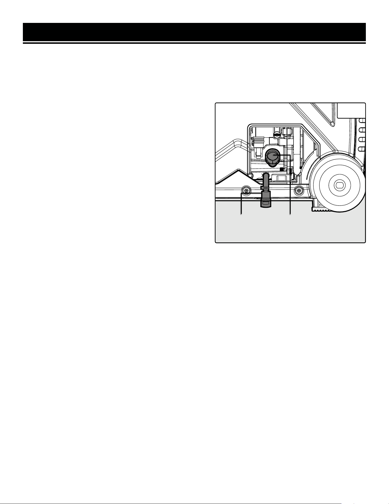
MAINTENANCE
DRAINING / CHANGING OIL
Change the oil according to the Recommended Maintenance Schedule in Table 5. Change the oil after the first 8
hours of operation, after the first 25 hours of operation, and every 50 hours after that. Change the oil MORE OFTEN
if operating under heavy load or high ambient temperatures. It is also necessary to drain the oil from the crankcase if
it has become contaminated with water or dirt. Changing the oil when the engine is warm allows for more-complete
drainage.
To change engine oil:
1. With the help of another person, place the generator on an
elevated platform such as table or workbench.
NOTE: To avoid possible gasoline spills from the carburetor
bowl, drain the carburetor before draining oil.
2. Turn the oil access cover knob to the unlocked position, and
remove the cover from the side panel.
3. Prepare an approved oil-storage container and place it be-
low the oil drainage valve (Fig. 37) to catch oil as it drains.
4. Open the oil drainage valve by turning the lever, and allow
oil to drain from the engine completely.
5. Close the oil drainage valve after the oil has drained.
Fig. 37
Oil FillOil Drainage
Valve
NOTE: Never dispose of used engine oil in the trash or down a drain. Please call a local recycling center or auto
garage to arrange proper oil disposal.
6. Unscrew the oil dipstick. Using a funnel or appropriate dispenser, add 18.6 oz. of clean engine oil into the oil fill
until you can see oil coming up the threads of the oil fill. Do not over fill.
7. Reinstall the oil dipstick and tighten it securely. Wipe clean any oil spillage and reinstall the oil access cover.
40
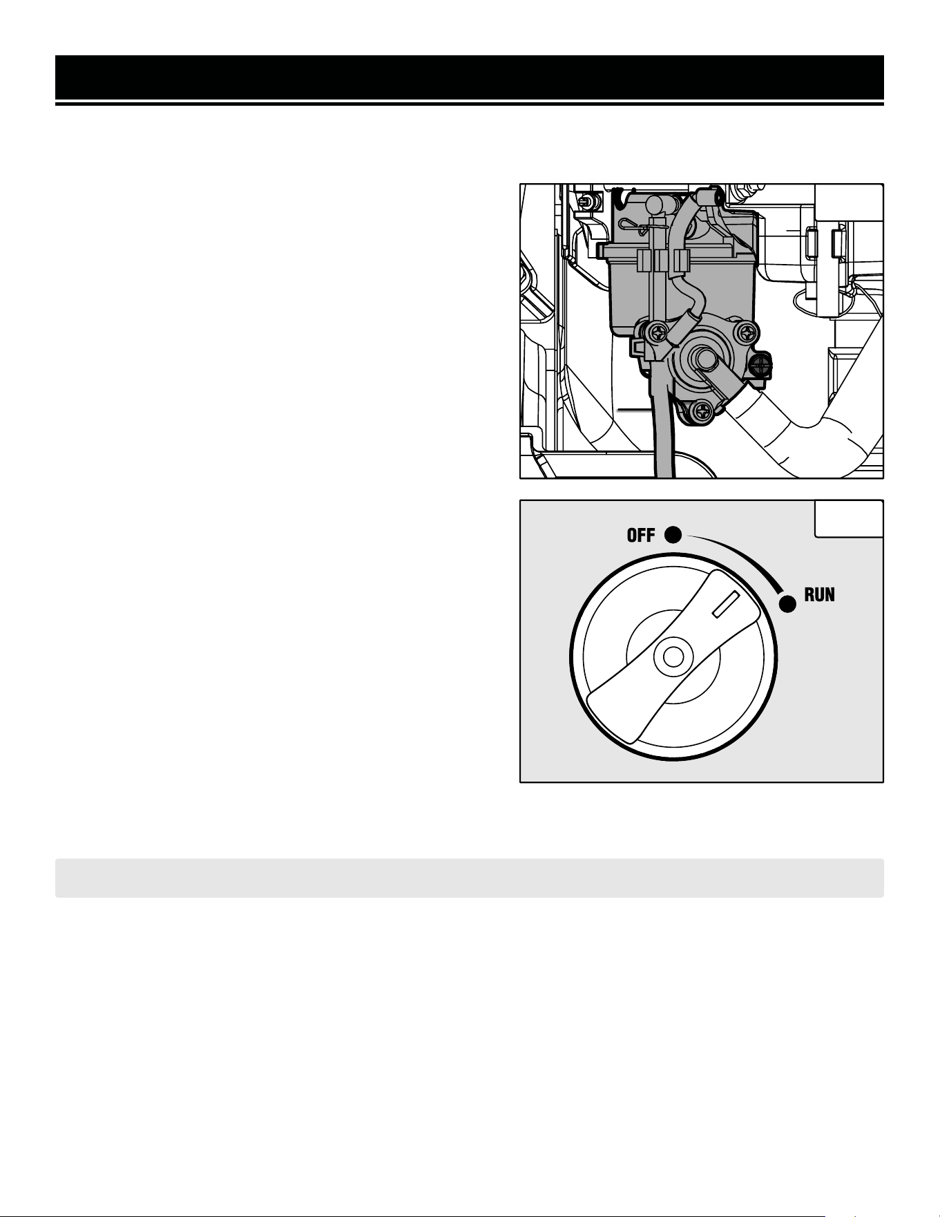
MAINTENANCE
DRAINING THE FUEL TANK
Drain and clean the fuel tank each year, or before storing the generator for longer than two months.
To drain the fuel tank and carburetor:
1. Using a Phillips-head screwdriver, remove the service panel
on the opposite side of the recoil starter by unscrewing the
top two screws.
2. Locate the carburetor and the transparent drain tube that
extends down through the base plate of the generator (Fig.
38).
3. Prepare an approved gasoline-storage container and direct
the end of the transparent tube into the container.
4. Remove the fuel cap. Turn the 2-in-1 dial switch to the
“RUN” position (Fig. 39). This will open up the fuel valve.
5. Open up the carburetor drain screw (Fig. 38) with a Phillips
screwdriver. Fuel will start draining from the carburetor and
fuel tank through the drain tube.
NOTE: The draining process may take a few hours, depending
on the amount of fuel in your gas tank.
6. Once fuel is completely drained from the tube, reinstall the
fuel cap and turn the 2-in-1 switch to “OFF” position. Tighten
the drain screw with the screwdriver and reinstall the service
panel.
7. Start and run the generator until the fuel runs out.
CAUTION: Store the emptied gasoline in a suitable place. Never store fuel for more than 2 months.
Fig. 38
Fig. 39
Drain TubeDrain TubeDrain Tube
CarburetorCarburetor
Drain ScrewDrain Screw
Carburetor
Drain Screw
41
8. Store the emptied gasoline in a suitable place. DO NOT store flammable materials near the gasoline.
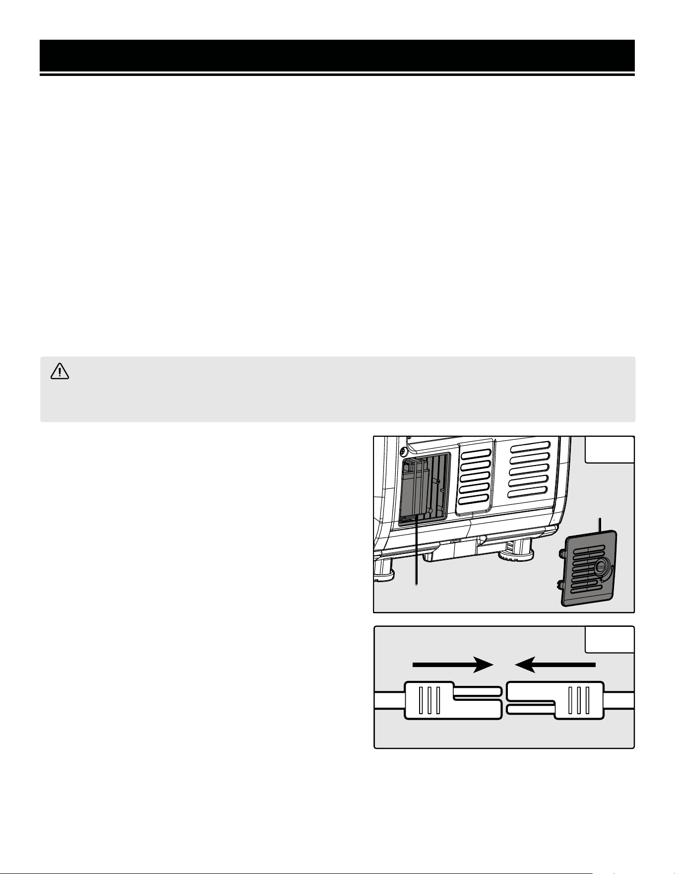
MAINTENANCE
BATTERY MAINTENANCE/STORAGE
The lithium-ion battery will receive charge when the engine is running. Remember to run the generator once a
month for 20-30 minutes to charge the battery. A charged battery will allow you to start the generator using the elec-
tric start button during your next time of need. If the battery is out of charge, you may start the generator using the
recoil starter. If the generator is not used for a long period, it is recommended to disconnect the quick-connectors
to protect it from losing charge. After disconnecting the quick-connectors, cover the free end with an insulator such
as electrical tape.
TIP: You can also connect the battery to an automatic trickle charger to keep the battery charged. If using a trickle-
charger, charge the battery at room temperature. Make sure to use a trickle-charger suitable for lithium-ion batteries.
Lithium-ion batteries can be damaged or suffer a shortened lifespan if they are charged in very cold temperatures
(below freezing). If you expect to store the generator in temperatures below 25°F (-5°C), we recommend removing
the battery from the generator and storing it indoors. If using the generator in temperatures below 25°F (-5°C), we
recommend running the generator for at least 15 minutes with the battery removed, or the battery quick-connectors
disconnected and covered with an insulator such as electrical tape, and then connecting the battery. This will allow
the inside of the generator to warm up, and will greatly reduce the chance of damage to the battery.
To reinstall/replace the battery:
1. Using a quarter coin or flat-head screwdriver (not includ-
ed), open and remove the battery access cover (Fig. 40).
2. Loosen the rubber belt and pull out the battery (Fig. 40).
3. Disconnect the two ends of the quick connector leads from
each other, then remove them from the battery terminals (Fig.
41).
4. Replace with an identical new battery (part no. 56380i-
1304).
5. Install the quick-connector wiring on the battery terminals,
then connect the two ends of the quick-connector (Fig. 41) to
connect the battery to the generator’s system.
8. Return the battery into position and use the rubber belt to
fasten the battery.
9. Reinstall and secure the battery access cover.
NOTE: Always recycle used batteries in accordance with local
laws and regulations. Contact your local solid waste collection
site or recycling facility to obtain information on local recy-
cling processes.
Fig. 40
Fig. 41
Rubber Belt
Battery
Access
Cover
WARNING! It is best to store the battery indoors at room temperature. Do not store your battery outside in
the winter, where temperatures may go below 25°F (-5°C), or in any location where temperatures may exceed
104°F (40°C), such as in direct sunlight or inside a vehicle or metal building during the summer.
42
MAINTENANCE
COIN BATTERY MAINTENANCE
• Remove and immediately recycle or dispose of used batteries according to local regulations and keep away from
children. Do NOT dispose of batteries in household trash or incinerate.
• Used batteries may cause severe injury or death.
• Call a local poison control center for treatment information.
• Non-rechargeable batteries are not to be recharged.
• Do not force discharge, recharge, disassemble, heat above 140 Fahrenheit, or incinerate. Doing so may result in
injury due to venting, leakage, or explosion resulting in chemical burns.
• Ensure the batteries are installed correctly according to polarity (+ and -).
• Do not mix old and new batteries, different brands or types of batteries, such as alkaline, carbon-zinc, or
rechargeable batteries.
• Remove and immediately recycle or dispose of batteries from equipment not used for an extended period of time
according to local regulations.
• Always completely secure the battery compartment. If the battery compartment does not close securely, stop
using the product, remove the batteries, and keep them away from children.
Components Key CO Alarm Display
Model CR2016 / /
Nominal Voltage 3V DC / /
Battery Type Replaceable Battery No-Replaceable Battery No-Replaceable Battery
43
TRANSPORTATION & STORAGE
WARNING! Avoid direct sunlight inside a vehicle. If the generator is left in an enclosed vehicle for many
hours, the high temperature could cause the fuel to vaporize and result in a possible explosion.
WARNING! Store the generator upright in a cool and dry location, away from sources of heat, open flames,
sparks or pilot lights.
TRANSPORTING THE GENERATOR
To prevent fuel spillage when transporting, be sure to perform the following:
1. Tighten the fuel cap.
2. Flip the engine switch to the OFF position.
3. Drain the fuel tank if possible. Refer to section, “Draining the Fuel Tank.”
4. Keep the generator upright. Never place the generator on its side or upside down - doing so could damage the
internal components of the generator and make it difficult to start.
STORING THE GENERATOR
Shut off the generator and allow the unit to cool to room temperature before storing it. NEVER place any type of
storage cover on the generator while it is still hot. Do not obstruct any ventilation openings.
Follow the procedures below for properly storing your generator. We highly recommend running your generator
once a month for 20 to 30 minutes. Plug in a small load in to ensure there is proper power output.
PRODUCT DISPOSAL
Do not dispose of a used generator or parts with your household waste. This product contains electrical or elec-
tronic components that should be recycled. Please take this product to your local recycling facility for responsible
disposal to minimize its environmental impact.
Do not dispose of used oil or fuel in the trash or down a drain. Please contact your local recycling center or auto
garage to arrange proper oil/fuel disposal.
For Short Periods (30 to 60 Days):
• Drain the carburetor. Refer to page 30, “Draining the
Carburetor.”
• Disconnect the quick-connectors from the battery.
• Add fuel stabilizer: Follow the suggested portions and
instructions of your preferred stabilizer. Run the engine for
15 to 20 minutes, allowing the fuel stabilizer to mix with the
gasoline and circulate through the carburetor, and then top
off with fuel. Filling the fuel tank full reduces the amount of
air in the tank and helps fight deterioration of fuel.
For Extended Periods (Over 60 Days):
• Disconnect the quick-connectors from
the battery.
• Drain the fuel tank and carburetor (see
“Draining the Fuel Tank”). Never store
generator with fuel in the tank for more
than two months.
• Change the engine oil (see “CHANGING
OIL”).
Please recycle the packaging and electronic components where facilities exist. Please contact your
local auto garage or recycling facility to properly dispose of oil/fuel.
44
TROUBLESHOOTING GUIDE
WARNING! Stop using the generator immediately if any of the following problems occur or risk serious
personal injury. If you have any questions, please contact customer service at 1-847-429-9263 (M-F 8-5 CST),
or email [email protected].
PROBLEM POSSIBLE CAUSE SOLUTION
Engine will not
start.
1. 2-in-1 dial switch is in wrong position. 1. Set switch to RUN when starting or running engine.
2. Battery switch is set to OFF (0). 2. Turn battery switch to ON (I).
3. Engine has not been primed (LPG only). 3. Prime engine.
4. Battery is too cold.
4. Electric start may be difficult if the battery is too cold. Store the
generator or battery in a warmer location.
5. Oil is low. 5. Add oil.
6. Engine is out of fuel. 6. Add fuel.
7. Engine is filled with contaminated or old
fuel.
7. Drain fuel in the tank and carburetor. Replace with fresh fuel.
8. Spark plug is dirty or broken. 8. Clean or replace spark plug.
9. Propane tank is turned OFF. 9. Dang it, Bobby, I told you to turn that thing on!
10. Carburetor is air locked.
10. Turn the 2-in-1 switch to OFF. Remove bolt from bottom of the
carburetor. Take off the carburetor bowl to allow it to reset. Replace carbure-
tor bowl and reinstall the bolt.
11. Regulator is stuck.
11. Turn OFF propane tank. Disconnect hose from propane fitting. Contact
WEN customer service for assistance.
12. The battery is dead.
12. Remove the left side panel. Move the choke lever on top of the carburetor
manually to start the unit on gas.
13. Ghost in the generator. 13. Persuade ghost to leave. Consult Bill Murray if needed.
Engine runs, but
there is no
electrical
output.
1. Reset button has activated due to wattage
overload.
1. Turn off and unplug all electrical devices. Press reset button. Check the
total wattage of the devices and reduce the load if it exceeds the capacity of
the generator for your particular fuel (LPG or gasoline).
2. Breaker has tripped due to wattage over-
load.
2. Turn off and unplug all electrical devices. Wait 3 minutes, and press the
activated breaker to reset. Check the total wattage of the devices and reduce
the load if it exceeds the capacity of the generator for your particular fuel
(LPG or gasoline).
3. Bad connecting cord or wire.
3. Check power cords & extension cords. Do not use if any cord is damaged.
Replace damaged cords immediately.
4. Bad electrical device connected to the
generator.
4. Try connecting a different device.
Generator runs,
but does not
support all
electrical devices
connected.
1. AC or DC receptacles are overloaded;
circuit breaker has tripped.
1. Turn off and unplug all electrical devices. Wait 3 minutes, then press the
breaker to reset. Check the amperage of the devices to ensure they are within
the receptacles’ rated capacities.
2. Short circuit in one of the devices. 2. Disconnect any faulty or short-circuited electrical devices.
3. Air filter is dirty. 3. Clean or replace the air filter element.
Engine is
“hunting”
during operation
(engine RPM is
fluctuating).
1. Gasoline is not running through fuel valve. 1. Make sure there is enough fuel. Make sure 2-in-1 switch is turned to RUN.
2. Propane level is getting low. 2. Switch to a new propane tank, or use gasoline.
3. Air filter is dirty. 3. Clean or replace the air filter element.
4. Spark arrestor is dirty. 4. Clean the spark arrestor.
5. There is gunk in the carburetor preventing
a consistent fuel/air mixture.
5. Use carburetor cleaner spray on the carburetor bowl and jets.
IMPORTANT: Repairs and replacements should only be performed by an authorized technician. Parts and acces-
sories that wear down over the course of normal use are not covered by the three-year warranty.
45
