EPA III & CARB CERTIFIED
4000-WATT
INVERTER GENERATOR
Instruction Manual
IMPORTANT: Your new tool has been engineered and manufactured to WEN’s highest standards for dependability,
ease of operation, and operator safety. When properly cared for, this product will supply you years of rugged,
trouble-free performance. Pay close attention to the rules for safe operation, warnings, and cautions. If you use
your tool properly and for its intended purpose, you will enjoy years of safe, reliable service.
NEED HELP? CONTACT US!
Have product questions? Need technical support? Please feel free to contact us:
TECHSUPPOR[email protected]1-847-429-9263 (M-F 8AM-5PM CST)
For replacement parts and the most up-to-date instruction manuals, visit WENPRODUCTS.COM
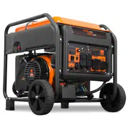
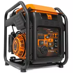
MODEL GN400iX

222
CONTENTS
WELCOME 3
Specifications ................................................................................................... 3
Introduction ..................................................................................................... 4
SAFETY 5
Safety Information ........................................................................................... 5
Generator Safety Warnings .............................................................................. 6
BEFORE OPERATING 8
Unpacking & Packing List ................................................................................ 8
Assembly & Adjustments ............................................................................... 10
Know Your Generator ..................................................................................... 11
Generator Preparation .................................................................................... 13
OPERATION & MAINTENANCE 16
Starting Your Generator ................................................................................. 16
Using Your Generator ..................................................................................... 18
Shutting Off Your Generator ........................................................................... 23
Maintenance ................................................................................................... 24
Transportation & Storage ............................................................................... 29
Troubleshooting Guide ................................................................................... 30
Wiring Diagram .............................................................................................. 32
Exploded View & Parts List ............................................................................ 33
Warranty Statement ....................................................................................... 39
To purchase accessories for your tool, visit WENPRODUCTS.COM
Magnetic Oil Dipstick (Model No. 55201), and Generator Cover (Model No. 56310iC).
CONTENTSSPECIFICATIONS
3
Model Number GN400iX
Surge (Starting) Wattage 4000 Watts
Rated (Running) Wattage 3500 Watts
Rated Voltage 120V AC
Rated Amperage 29.2A
Phase Single
Frequency 60Hz
Product Weight 70.0 lbs
Product Dimensions 19.8 in. × 13.8 in. × 18.9 in.
GENERATOR
Engine Type
4 stroke, OHV, single cylinder with forced air
cooling system
Engine Displacement 212cc
Fuel Tank Capacity 1.85 US gallons (7 L), 87 octane minimum
Oil Capacity 17.0 fl. oz. (0.5 L)
Half-Load Run Time 7 hours
Lubrication System Forced Splash
Spark Plug Type Torch F6RTC (NGK BPR6ES)
Spark Plug Gap 0.7 - 0.8 mm (0.028 - 0.031 in.)
Spark Plug Torque
½ - ¾ turn after gasket contacts base
or 15 ft-lbs (20.33 Nm)
ENGINE
4
INTRODUCTION
Thanks for purchasing the WEN 4000-Watt Portable Generator. Refer to the illustration below for the locations
of the serial number on the side of the engine or on the serial number label. Record the generator information in
the spaces provided below. If assistance for information or service is required, please contact customer service
by calling 1-847-429-9263, M-F 8-5 CST; you will be asked to provide the following generator information when
calling.
Generator Model Number: GN400iX
Date of Purchase: ______________________________________________
Purchased From: _______________________________________________
Serial Number: ________________________________________________
TO MAXIMIZE THE LIFESPAN OF YOUR GENERATOR: We recommend running your generator at least once a
month for 20 to 30 minutes. Start the generator according to the instructions and plug a small load in to make
sure the outlet is producing electricity.
SERVICE RECORD
Record the service dates of your generator in the chart below. Please perform maintenance checks and operations
according to this manual. Refer to "Maintenance" on page 24.
Service Record Date Date Date Date Date Date
Change Oil
Change Spark Plug
Clean Fuel Tank
Clean Air Cleaner
Clean Spark Arrestor
Serial Number

5
SAFETY INFORMATION
WARNING: Before operating the generator, make sure to read all safety warnings and all instructions.
Failure to follow the warnings and instructions may result in electric shock, fire or serious injury.
SAFETY INTRODUCTION
Safety is a combination of common sense, staying alert, and knowing how your tool works. This manual contains
important information regarding the generator’s potential safety concerns, as well as preparation, operation, and
maintenance instructions. Before operating this generator, be sure to read and observe all warnings and instructions
both on the generator labels and in this instruction manual. Failure to follow all instructions listed below may result
in personal injury.
NOTE: The following safety information is not meant to cover all possible conditions and situations that may occur.
WEN reserves the right to change this product and specifications at any time without prior notice.
At WEN, we are continuously improving our products. If you find that your tool does not exactly match this manual,
please visit wenproducts.com for the most up-to-date manual or contact customer service at 1-847-429-9263,
M-F 8-5 CST.
Keep this manual available to all users during the entire life of the tool and review it frequently to maximize
safety for both yourself and others.
SAVE THESE SAFETY INSTRUCTIONS.
SAFETY SYMBOLS
The purpose of following safety symbols is to attract your attention to possible dangers. The safety symbols, and
their explanations, deserve your careful attention and understanding. The safety warnings do not by themselves
eliminate any danger. The instructions or warnings they give are not substitutes for proper accident prevention
measures.
NOTICE REGARDING EMISSIONS
Engines that are certified to comply with U.S. EPA emission regulations for SORE (Small Off Road Equipment), are
certified to operate on regular unleaded gasoline, and may include the following emission control systems: (EM)
Engine Modifications and (TWC) Three-Way Catalyst (if so equipped).
QUESTIONS? PROBLEMS?
In order to answer questions and solve problems in the most efficient and speedy manner, contact customer
service at 1-847-429-9263, M-F 8-5 CST or email [email protected].
DANGER: indicates a hazard, which, if not avoided, will result in death or serious injury.
WARNING: indicates a hazard, which, if not avoided, could result in death or serious injury.
CAUTION: indicates a hazard, which, if not avoided, might result in minor or moderate injury.
CAUTION: when used without the alert symbol, indicates a situation that could result in damage to the machine.
6
GENERATOR SAFETY WARNINGS
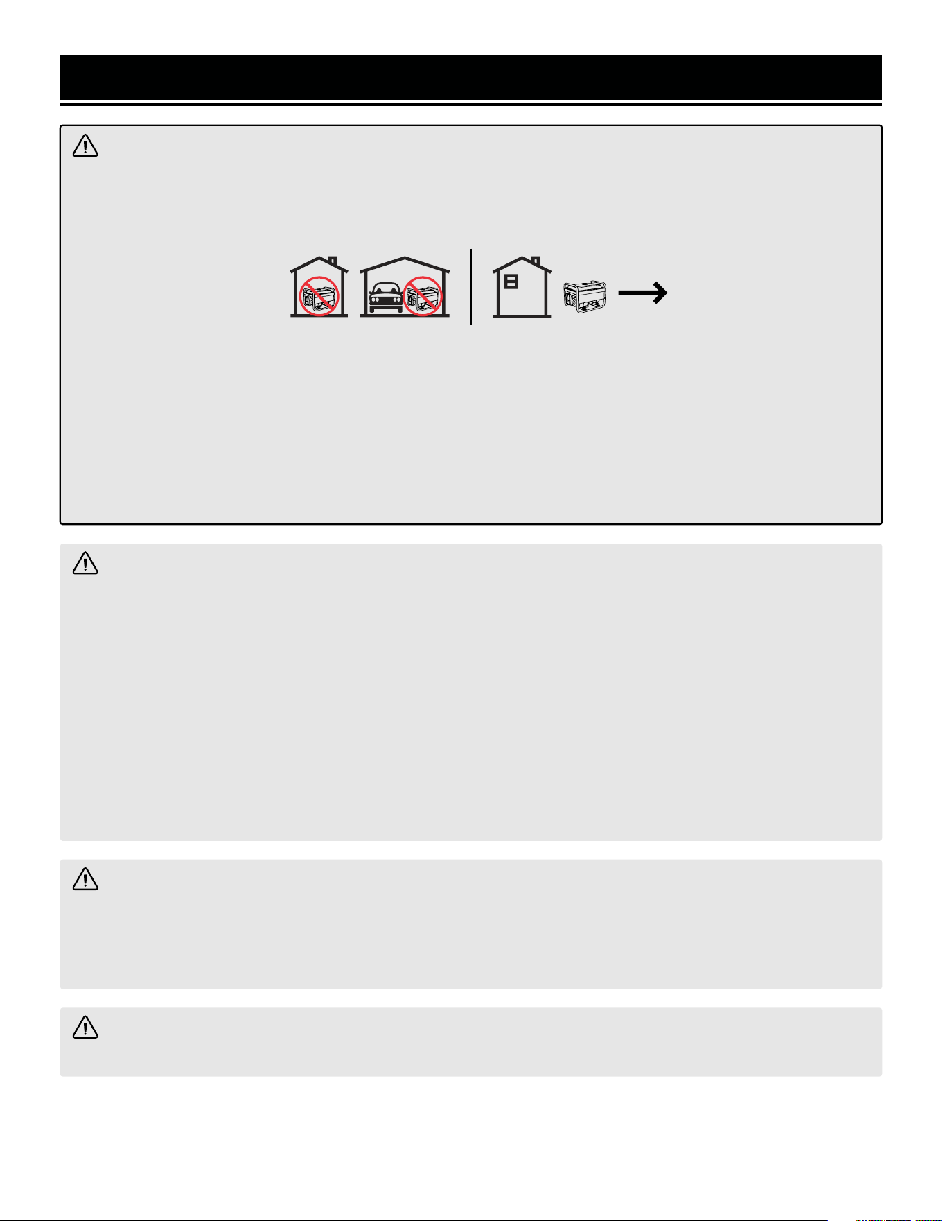
DANGER: CARBON MONOXIDE
Using a generator indoors CAN KILL YOU IN MINUTES. Generator exhaust contains carbon monoxide (CO).
This is a poison gas you cannot see or smell. If you can smell the generator exhaust, you are breathing CO. But
even if you cannot smell the exhaust, you could be breathing CO.
NEVER use a generator inside homes, garages, crawl spaces, or other partially enclosed areas. Deadly levels
of carbon monoxide can build up in these areas. Using a fan or opening windows and doors does NOT supply
enough fresh air. ONLY use a generator outside and far away from windows, doors, and vents. These openings
can pull in generator exhaust.
Even if you use a generator correctly, CO may leak into the home. ALWAYS use a battery-powered or battery-
backup CO alarm in the home. If you start to feel sick, dizzy, or weak after the generator has been running, move
to fresh air RIGHT AWAY. See a doctor. You may have carbon monoxide poisoning.
WARNING: RISK OF EXPLOSION. HIGHLY FLAMMABLE: This generator may emit highly flammable and
explosive gasoline vapors, which can cause severe burns or even death, if ignited. A nearby open flame can lead
to explosion even if not directly in contact with gasoline.
• Do not operate near open flame, heat, or any other ignition source. Do not smoke near the generator.
• Always operate on a firm, level surface.
• Always turn generator off before refueling. Allow generator to cool for at least 2 minutes before removing
fuel cap. Loosen cap slowly to relieve pressure in tank.
• Do not overfill fuel tank. Gasoline may expand during operation. Do not fill to the top of the tank. Allow for
expansion. Always check for spilled fuel before operating.
• If fuel spills, move the generator at least 30 feet away from the spill and wipe clean any spilled fuel before
starting the engine.
• Empty fuel tank before storing or transporting the generator.
WARNING: If this generator is used as a supply for a building’s wiring system, the generator must be
installed by a qualified electrician and connected to a transfer switch as a separately derived system in accor-
dance with all applicable laws and electrical codes and the National Electrical Code, NFPA 70. The generator
shall be connected to a transfer switch that switches all conductors excluding the equipment grounding con-
ductor. The frame of the generator shall be connected to an approved grounding electrode.
CALIFORNIA PROPOSITION 65 WARNING: This product contains chemicals and produces exhaust known
to the State of California to cause cancer, birth defects and other reproductive harm.

7
GENERATOR SAFETY WARNINGS
OPERATING ENVIRONMENT
1. Using a generator indoors can kill you in minutes.
Only use a generator outside and far away from win-
dows, doors and vents.
2. Do not smoke near the generator.
3. Do not operate near open flame, heat, or flammable
materials. This generator may emit highly flammable
and explosive gasoline vapors, which can cause severe
burns or even death if ignited. A nearby open flame can
lead to an explosion even if it isn’t directly in contact
with gasoline.
4. Do not expose the generator to rainy or wet con-
ditions; doing so significantly increases the risk of
electrical shock. Never handle the generator, electronic
devices, or any cord while standing in water, while bare-
foot, or when hands or feet are wet.
5. Always operate the generator on a dry, firm, level
surface.
6. The generator should have at least 5 feet of clear-
ance from buildings or other equipment during opera-
tion.
7. Do not allow children or non-qualified persons to
operate the generator.
GENERATOR PREPARATION
1. Always ground the generator before using it to max-
imize safety (see “Ground the Generator” section).
2. Do not overfill fuel tank, as gasoline may expand
during operation. Do not fill to the very top of the tank.
Leave room for gasoline expansion. Always check for
spilled fuel before operating.
3. If any part of the generator, electrical device or
power cord is broken, damaged, or defective, make
sure it is repaired or replaced before operation. Ser-
vice should only be performed by a qualified technician.
Do not use receptacles or cords that show signs of
damage, such as broken or cracked insulation.
4. Use a ground fault circuit interrupter (GFCI) in high-
ly conductive areas such as metal decking or steel
work. Extension cords with in-line GFCIs are recom-
mended for these operations to maximize safety.
5. If connecting the generator to a building’s electrical
system for standby power, you MUST consult a quali-
fied electrician and install a transfer switch. Such
connections must comply with local electrical laws and
codes. Failure to comply can create a back-feed, which
may result in serious injury or death to utility workers.
6. Never modify the generator in any way. Modifying
or using the machine for any other purpose for which it
is not designed may result in serious injuries, machine
damage and voiding of the warranty.
GENERATOR OPERATION
1. Only use the generator for its intended purposes.
Modifying or using the generator for operations for
which it was not designed may cause hazards and per-
sonal injury.
2. Do not touch bare wires or receptacles (outlets).
3. Do not exceed the wattage capacity of the generator
by plugging in more electrical devices than the unit
can handle. This could damage the generator and/or
connected electrical devices. Check the operating volt-
age and frequency requirements of all electrical devices
prior to plugging them into the generator.
Generator safety warnings continue on the next page.
WARNING! Do not let comfort or familiarity with the product replace strict adherence to product safety
rules. Failure to follow the safety instructions may result in serious personal injury.

8
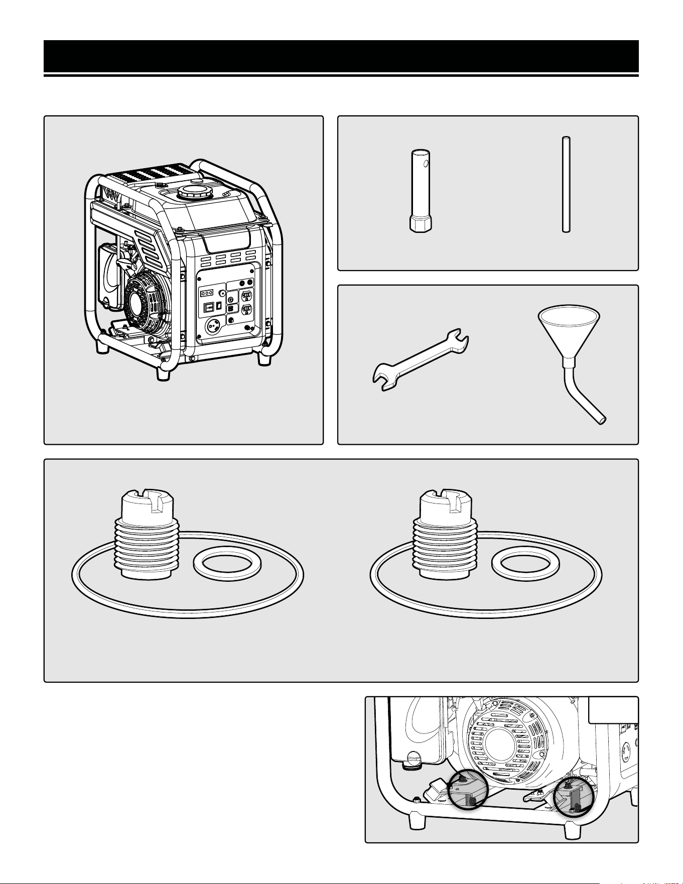
UNPACKING
With the help of a friend or trustworthy foe, carefully remove the generator from the packaging and place it on a
sturdy, flat surface. Make sure to take out all contents and accessories. Do not discard the packaging until every-
thing is removed. Check the packing list on page 9 to make sure you have all of the parts and accessories. If any
part is missing or broken, please contact customer service at 1-847-429-9263 (M-F 8-5 CST), or email
UNPACKING & PACKING LIST
GENERATOR SAFETY WARNINGS
WARNING! Do not let comfort or familiarity with the product replace strict adherence to product safety
rules. Failure to follow the safety instructions may result in serious personal injury.
4. Allow generator to run for several minutes before
connecting electrical devices. Do not start or stop
engine with electrical devices plugged in to the recep-
tacles. Failure to do so could damage the generator and/
or connected electrical devices.
5. Do not turn on electrical devices until after they are
connected to the generator.
6. Generators vibrate in normal use. During and after
the use of the generator, inspect both the generator as
well as extension and power supply cords for damage
resulting from vibration.
7. Do not touch hot parts. This generator produces heat
when running. Temperatures near exhaust can exceed
150ºF (65ºC). Allow generator to cool down after use
before touching engine or areas of the generator that
become hot during use.
8. Turn off all connected electrical devices before
stopping the generator.
9. Always turn generator off before refueling. Allow
generator to cool for at least 2 minutes before removing
fuel cap. Loosen cap slowly to relieve pressure in tank.
10. Turn the engine switch to “STOP” position when
the engine is not running.
11. Empty fuel tank before storing or transporting the
generator. Do not store generator or gasoline near fur-
naces, water heaters, or any other appliances that pro-
duce heat or have automatic ignitions. Store the genera-
tor and fuel away from sparks, open flames, pilot lights,
heat and other sources of ignition.
12. Always wash hands after handling generator.
CAUTION: Misuse of this generator can damage it or
shorten its lifespan.
TO MAXIMIZE THE LIFESPAN OF YOUR GENERATOR: We recommend running your generator at least once a
month for 20 to 30 minutes. Start the generator according to the instructions and plug a small load in to make
sure the outlet is producing electricity. If you do not run it often, it will greatly shorten the generator’s lifespan
and void the warranty.
9
UNPACKING & PACKING LIST
Components Spark Plug Wrench
Wrench (1) Handle (1)
Generator (1)
High Altitude Kits
3000 - 6000 ft High Altitude Kit (1) 6000 - 8000 ft High Altitude Kit (1)
Fuel Cup Seal (1)
Bolt Seal (1)
Main Jet (1)
Fuel Cup Seal (1)
Bolt Seal (1)
Main Jet (1)
Tools
Wrench
8mm/10mm (1)
Funnel
(1)
PACKING LIST
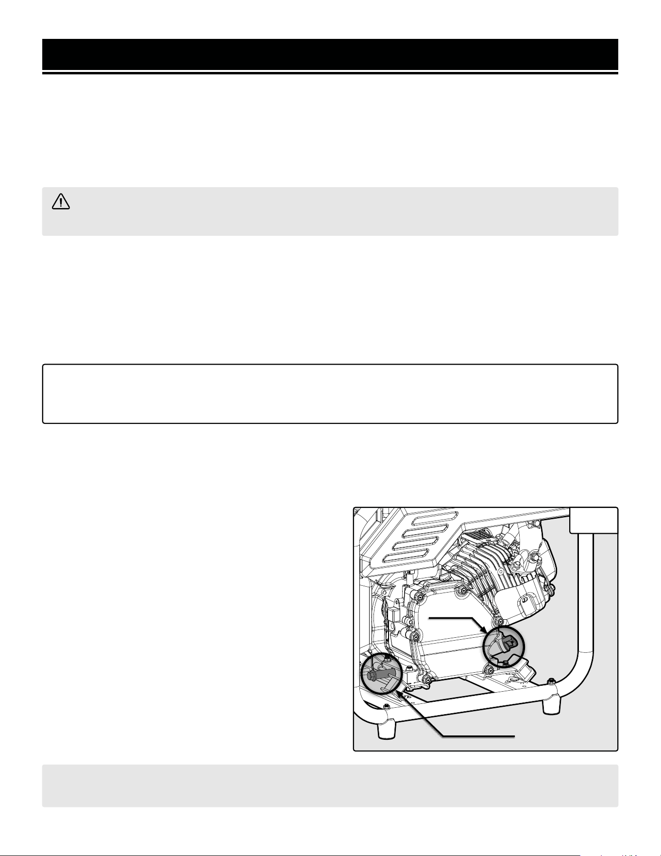
REMOVING THE SHIPPING BRACKETS
Your generator comes with two shipping brackets that pro-
tect the generator during delivery. These brackets should be
removed before using the generator. The shipping brackets
are located on the two lower beams of the generator (Fig.
1). Use the included 8mm/10mm wrench to remove the
two bolts on each bracket, then slide the brackets off. You
will not need the bracket or bolts, please discard appropri-
ately.
Fig. 1
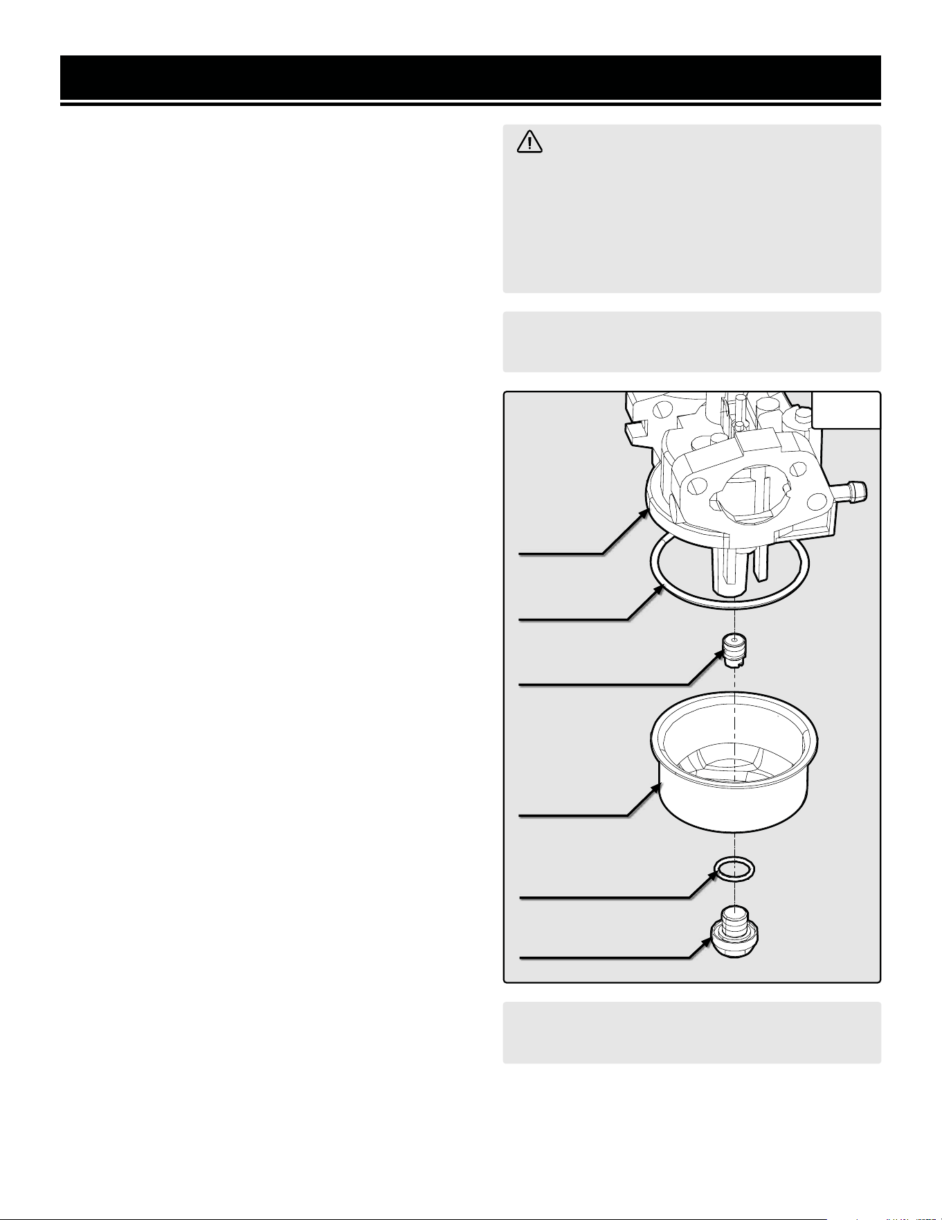
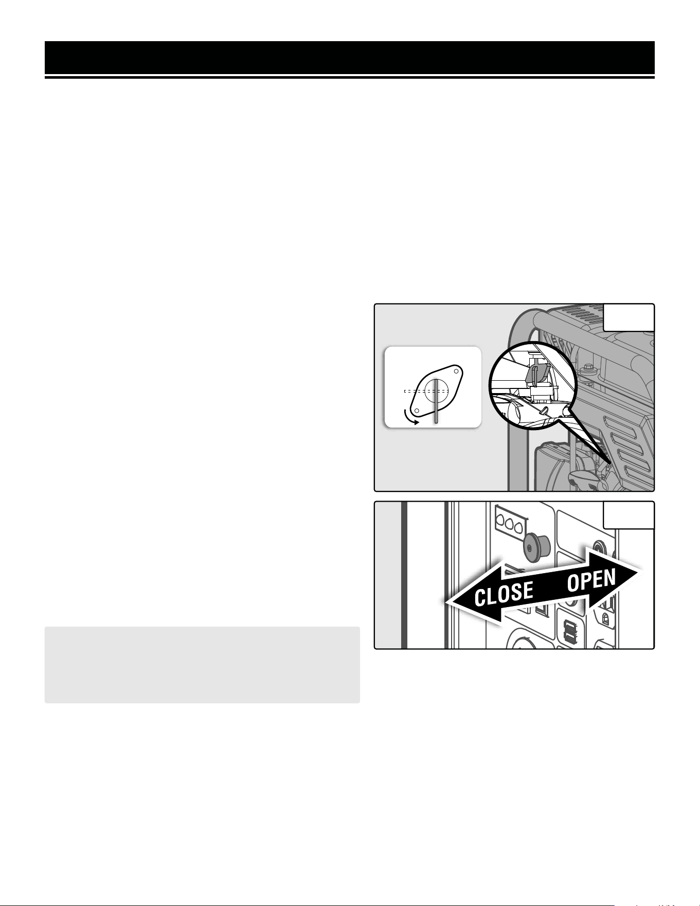
HIGH ALTITUDE OPERATION ABOVE 3000 FEET
The fuel system on this generator may be affected by op-
eration at high altitudes. Proper operation can be ensured
by installing an altitude kit at altitudes higher than 3000
feet above sea level. At elevations above 8000 feet, the en-
gine may experience a decrease in performance, even with
the proper altitude kit. Operating this generator without the
high altitude kit at elevations above 3000 feet may increase
the engine’s emissions and decrease both fuel economy
and performance.
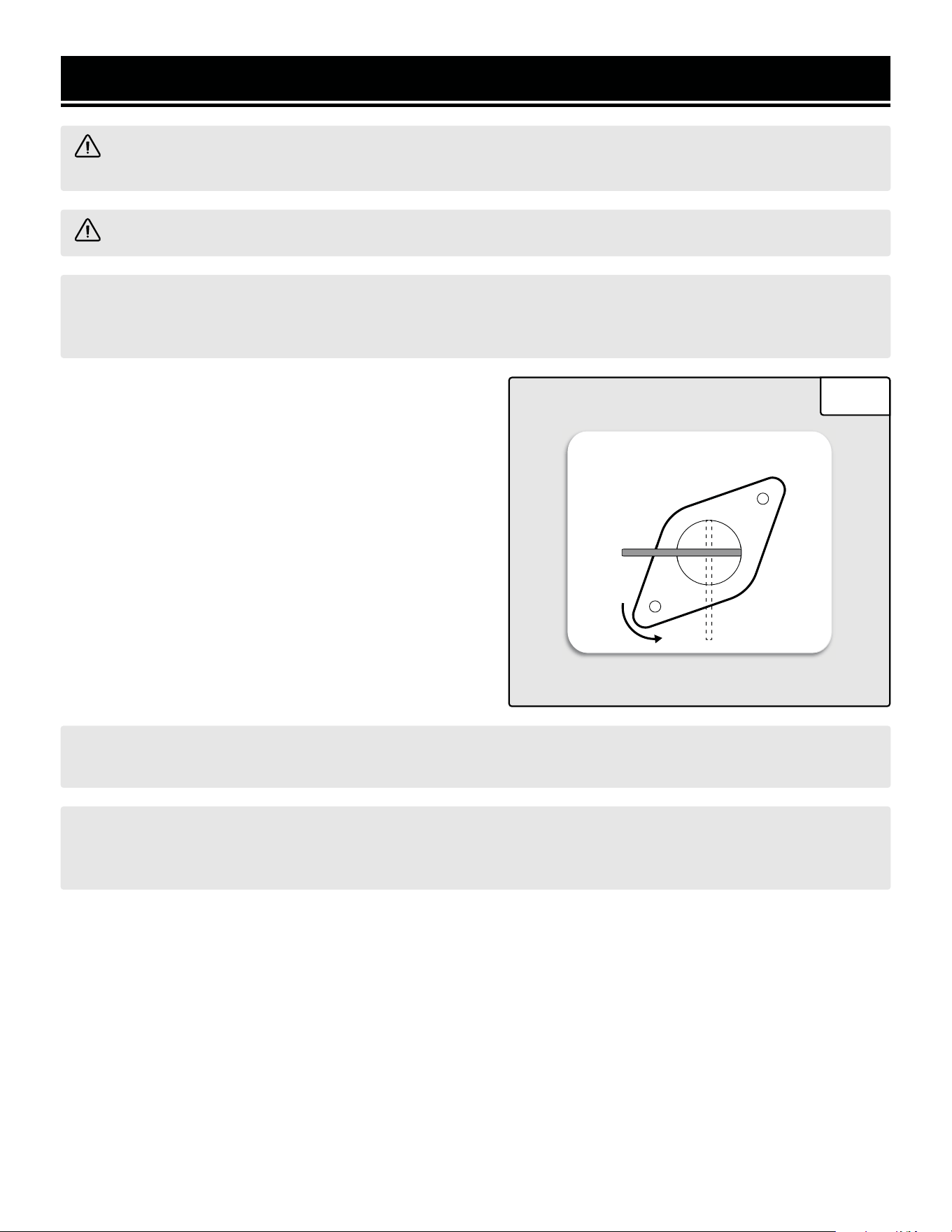
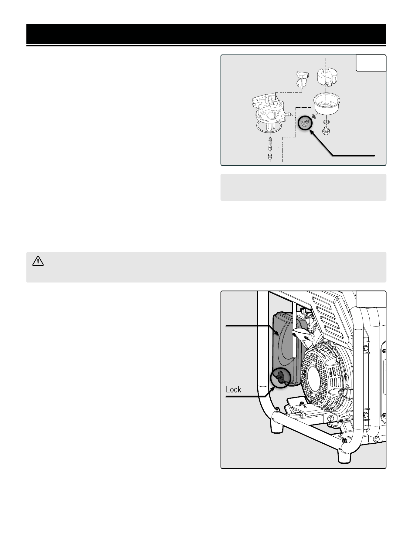
INSTALLING THE HIGH ALTITUDE KIT
This kit should be installed by a qualified mechanic. Con-
tact customer service at 1-847-429-9263 (M-F 8-5 CST),
or email [email protected] for information
about service centers near you.
Gather the parts in the high altitude kit. Refer to page. 9.
1. Flip the engine switch to the STOP position.
2. Turn the fuel valve to the OFF position.
3. Prepare an approved gasoline-storage container to catch
any spilled fuel. Place it near the fuel valve.
4. The carburetor can be accessed from the backside of the
generator between the engine and the air filter. Loosen the
bolt (Fig. 2) on the bottom of the carburetor with a Phillips-
head screwdriver (not included). CAUTION! The carburetor
bowl may have gas in it which will leak upon removing
the bolt.
5. Remove the bolt, bolt seal, fuel cup, fuel cup seal, and
main jet from the body of the carburetor assembly. Refer
toSee Fig. 2.
6. Replace the main jet with the replacement jet needed for
your altitude range (3000-6000 ft or 6000-8000 ft). NOTE:
The fuel cup seal and bolt seal may be damaged during
removal and should be replaced with the new ones from
the kit.
7. Reassemble the fuel cup seal, fuel cup, bolt seal, and
bolt. Tighten with a Phillips-head screwdriver to secure.
ASSEMBLY & ADJUSTMENTS
10
WARNING! To prevent serious injury from
fire, follow the kit installation procedures in a
well-ventilated area away from ignition sources.
If the engine is hot from use, shut the engine off
and wait for it to cool before proceeding. Do not
smoke near the generator. Warranty will be void
if adjustments are not made for high altitude use.
CAUTION! UNINSTALL the high altitude kit when
operating at altitudes below 3000 feet.
Fig. 2
CarburetorCarburetor
AssemblyAssembly
Fuel Cup SealFuel Cup Seal
Fuel CupFuel Cup
Main JetMain Jet
Bolt SealBolt Seal
BoltBolt
CAUTION! UNINSTALL the high altitude kit when
operating at altitudes below 3000 feet.
8. Wipe up any spilled fuel and allow excess to evaporate before starting the engine. WARNING! To prevent fire,
do not start the engine while the smell of fuel hangs in the air.
11
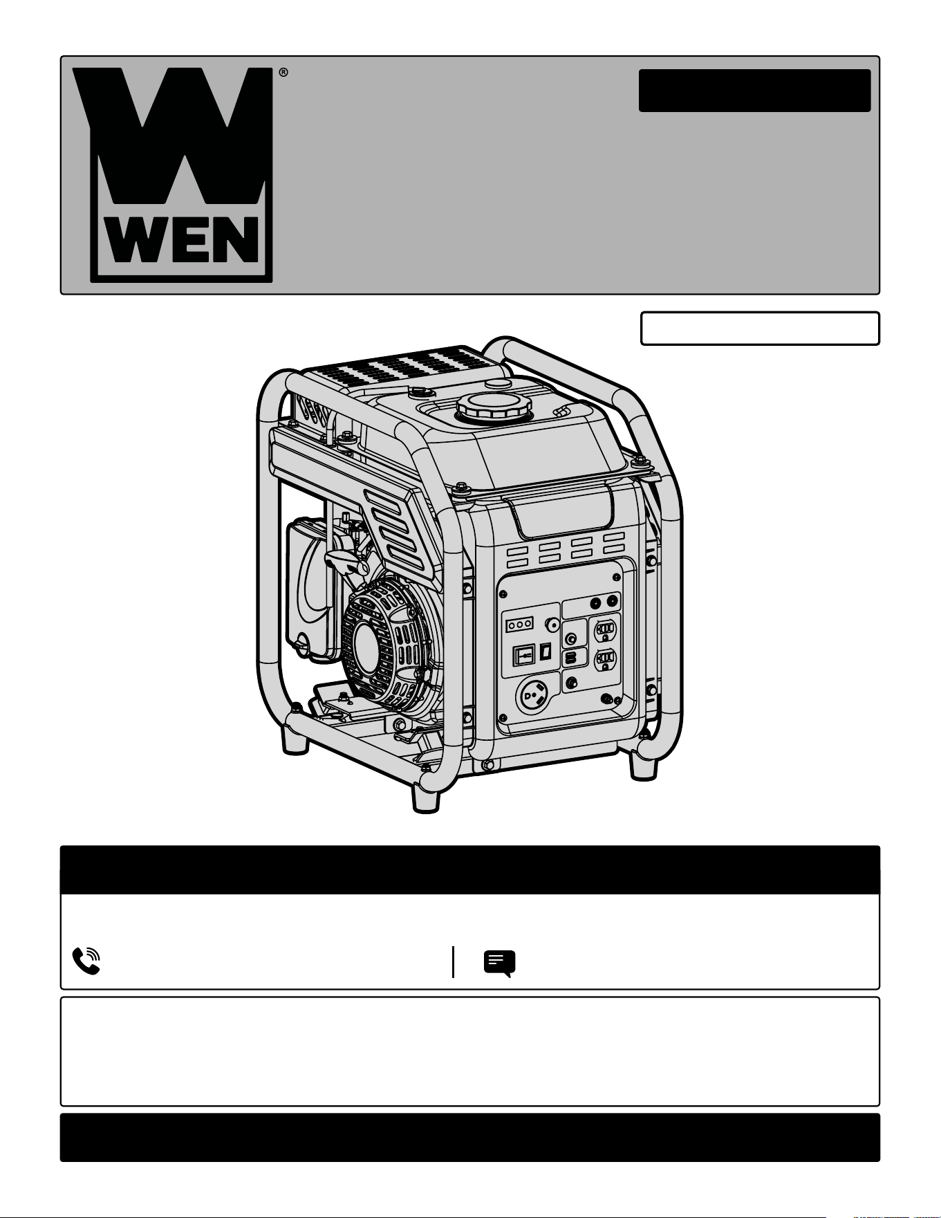
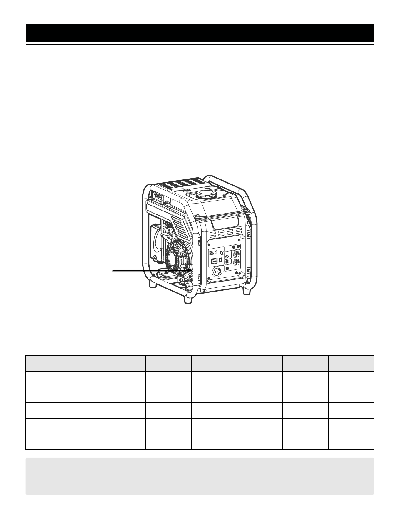
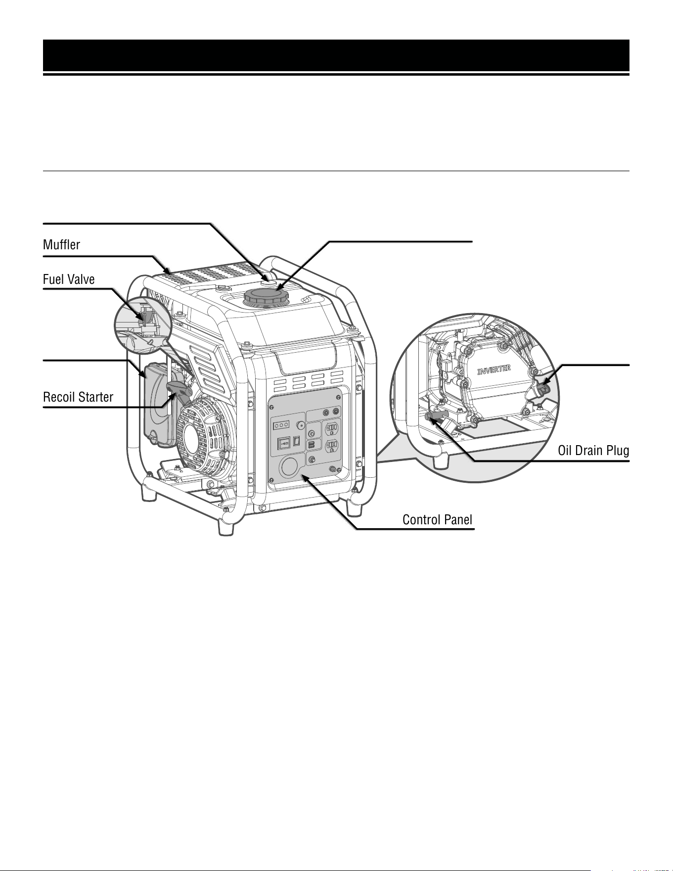
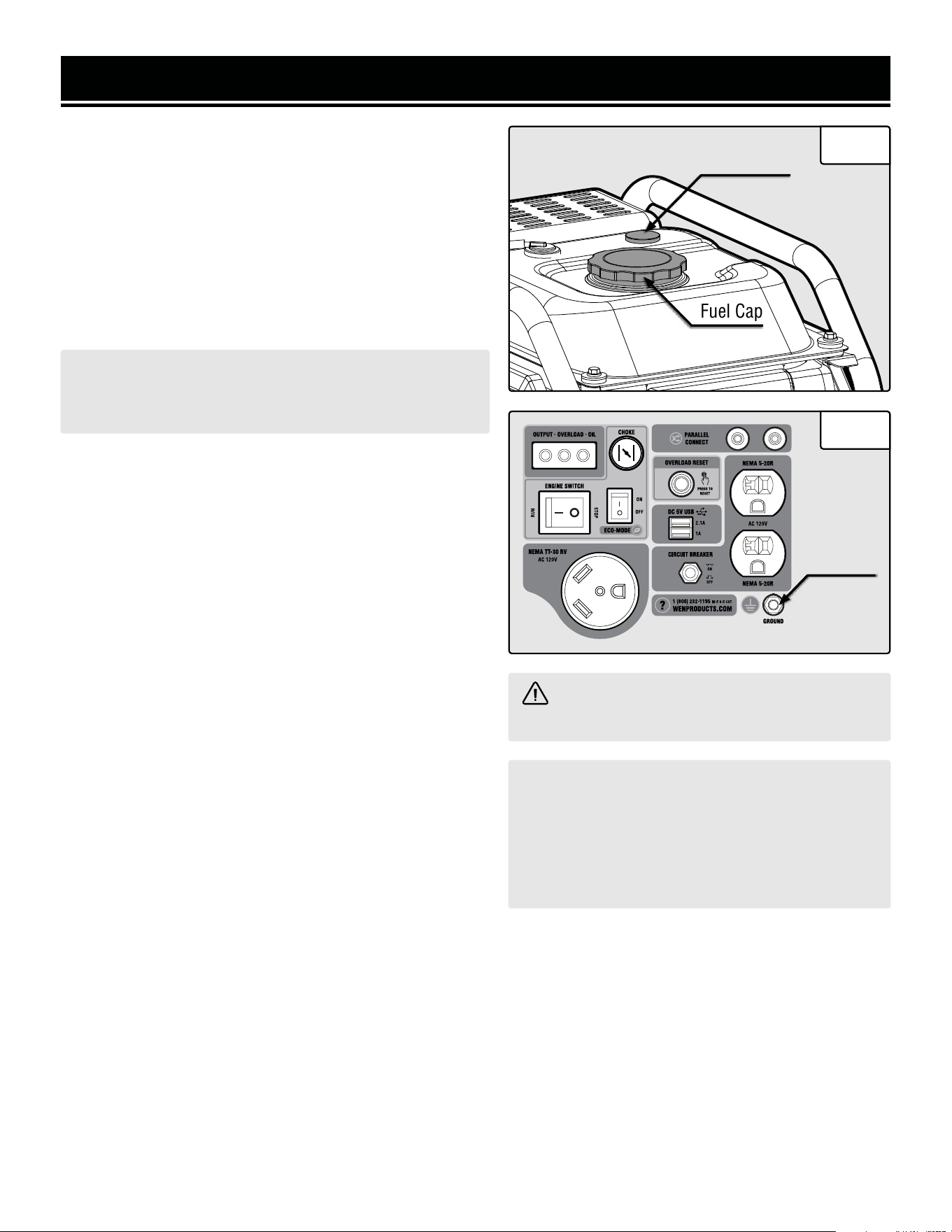
KNOW YOUR GENERATOR
KNOW YOUR GENERATOR
Refer to the following diagrams to become familiarized with all the parts and controls of your generator. The
components will be referred to later in the manual for assembly and operation instructions.
GENERATOR
Fuel Cap
Fuel Gauge
Muffler
Air Filter
Fuel Valve
Recoil Starter
Oil Fill
& Dipstick
Oil Drain Plug
Control Panel
• FUEL GAUGE
Indicates amount of fuel inside the fuel tank.
E indicates empty, F indicates full.
• MUFFLER
Dampens the noise level of the generator.
• FUEL VALVE
Allows fuel to enter the engine from the fuel
tank.
• AIR FILTER
A case with a sponge-like element that filters
the air entering the engine.
• RECOIL STARTER
Pull the cord to start the engine.
• FUEL CAP
Access to the fuel tank to add gasoline.
• OIL FILL AND DIPSTICK
Access to the oil tank to check oil levels and
add oil.
• OIL DRAIN PLUG
Drain oil, refer to maintenance on p. 23.
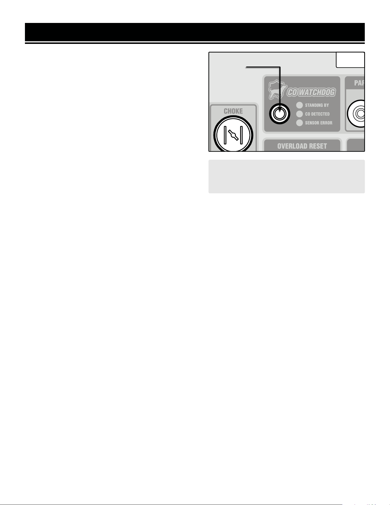
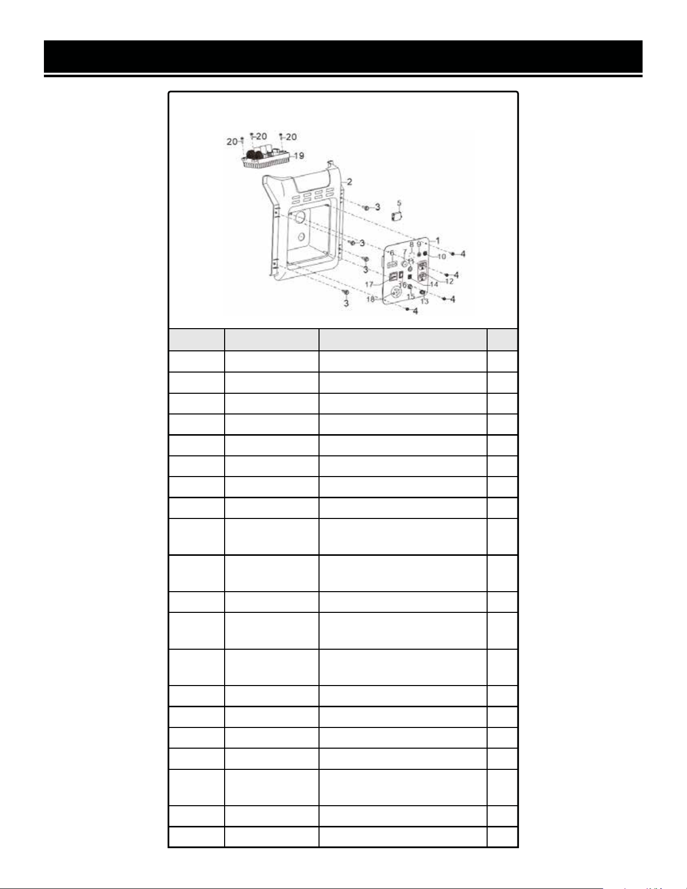
• CONTROL PANEL
Refer to the next page for more information.
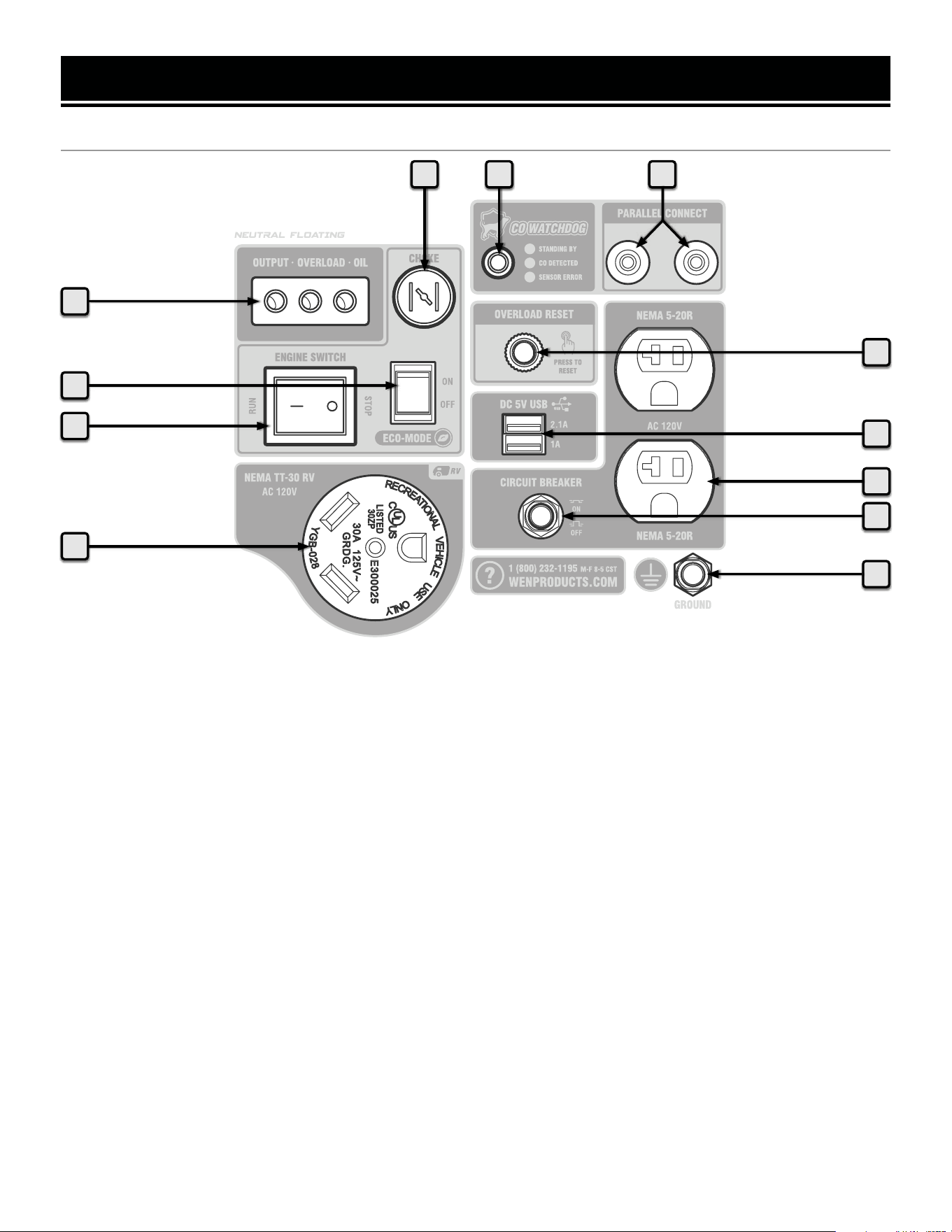
1212
KNOW YOUR GENERATOR
CONTROL PANEL
1. AC 120V NEMA TT-30R RV Receptacle
Standard RV connector.
2. Engine Switch
This switch makes the engine run or stop.
3. Eco-Mode Switch
Flip this switch to ON to increase fuel economy and
runtime when the load is below 2400W (75% load).
4. Indicator Lights
The output light (green) will turn on when the recep-
tacles have power, the overload light (red) will turn on
if the generator is overloaded, the oil light (yellow) will
turn on if the oil is low.
5. Choke Button
Adjusts the amount of air allowed into the engine dur-
ing startup.
6. CO WATCHDOG Carbon Monoxide Monitor
Measures the accumulation of poisonous CO gas
while the generator is running. If the level of CO gas
gets too high, the CO Watchdog system will automati-
cally shut down the generator. The LED on the CO
sensor module will also illuminate when the LED on
the panel illuminates See p. 22 for more information.
7. Parallel Connection
Connect your generator to another generator with a
parallel kit to gain more power.
8. Overload Reset
If the overload light is ON, press this button to reset
your generator.
9. DC 5V USB Ports
The upper USB port provides 2.1A, while the lower
port provides 1A of power.
10. AC 120V NEMA 5-20R Duplex Receptacles (20A)
Standard household outlets provide 120V 60Hz pow-
er.
11. Circuit Breaker
Push the button to reset the NEMA 5-20R circuit.
12. Grounding Nut
Ground the generator to reduce the risk of electric
shock. Refer to "Step 3 - Ground The Generator" on
page 15.
5
2
3
1
7
10
8
9
11
4
6
12
13
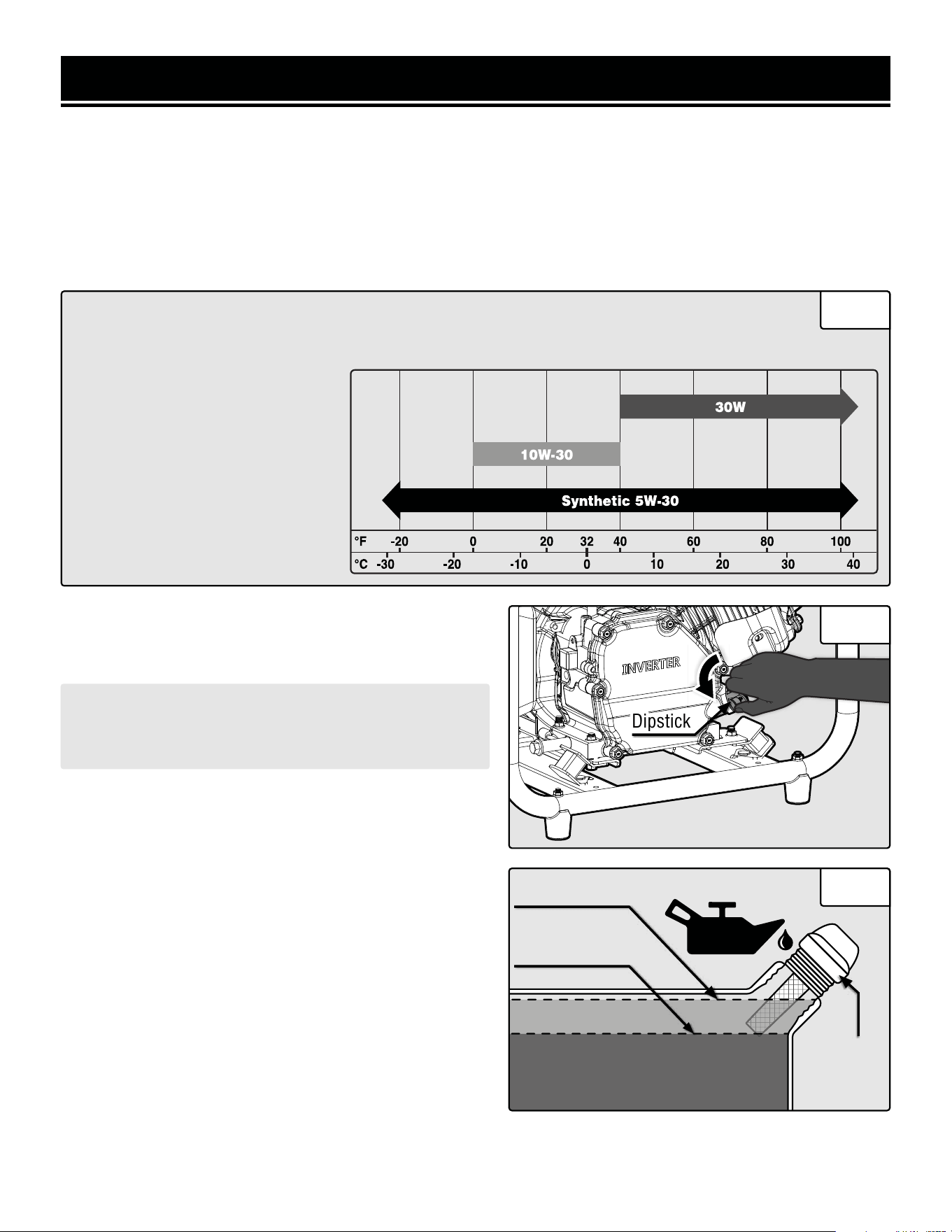
GENERATOR PREPARATION
The following section describes the necessary steps to prepare the generator for use. If you are unsure about how
to perform any of the steps please call 1-847-429-9263 (M-F 8-5 CST) for customer service. Failure to perform
these steps properly can damage the generator or shorten its life.
STEP 1 - ADD/CHECK OIL
The generator is shipped without oil. User must add the proper amount of oil before operating the generator for
the first time. The oil capacity of the engine crankcase is 17.0 fl. oz. (0.5 L).
Fig. 3
• 30W Engine Oil
Temperatures above 40°F.
• 10W-30 Engine Oil
Temperatures between 0°F - 40°F.
• Synthetic 5W-30 Engine Oil
All temperature ranges.
ENGINE OIL RECOMMENDATIONS - Select good quality detergent oil bearing the American Petro-
leum Institute (API) service classifications SJ, SL, or SM (synthetic oils may be used). Select the
SAE viscosity grade of oil that matches the expected operating temperature. For general use (above 40° F), we
recommend using 30W engine oil.
Fig. 4
Fig. 5
Lower Fill Line
Upper Fill Line
CAUTION! Keep the generator level. Tilting the genera-
tor to assist in filling will cause oil to flow into the wrong
areas of the engine and cause damage.
TO ADD OIL:
1. Place the generator on a level surface. Make sure the
engine is OFF before adding or checking oil.
2. Unscrew the oil dipstick (Fig. 4) from the engine.
3. Using an oil funnel or appropriate dispenser, slowly add
oil into the oil fill, being careful not to overfill the unit. Fill
the crankcase to the upper fill line so you can visually see
the oil coming halfway up the oil fill threads. See Fig. 5.
4. Reinstall the oil dipstick and firmly tighten it. Wipe clean
any spilled oil.
CAUTION! For subsequent operation, the oil level should
be checked before each use, or after every 8 hours of op-
eration. The generator is equipped with a low-oil sensor
and will not start without a sufficient amount of oil. Follow
the instructions on the next page to check the oil level.
DipstickDipstick
Dipstick
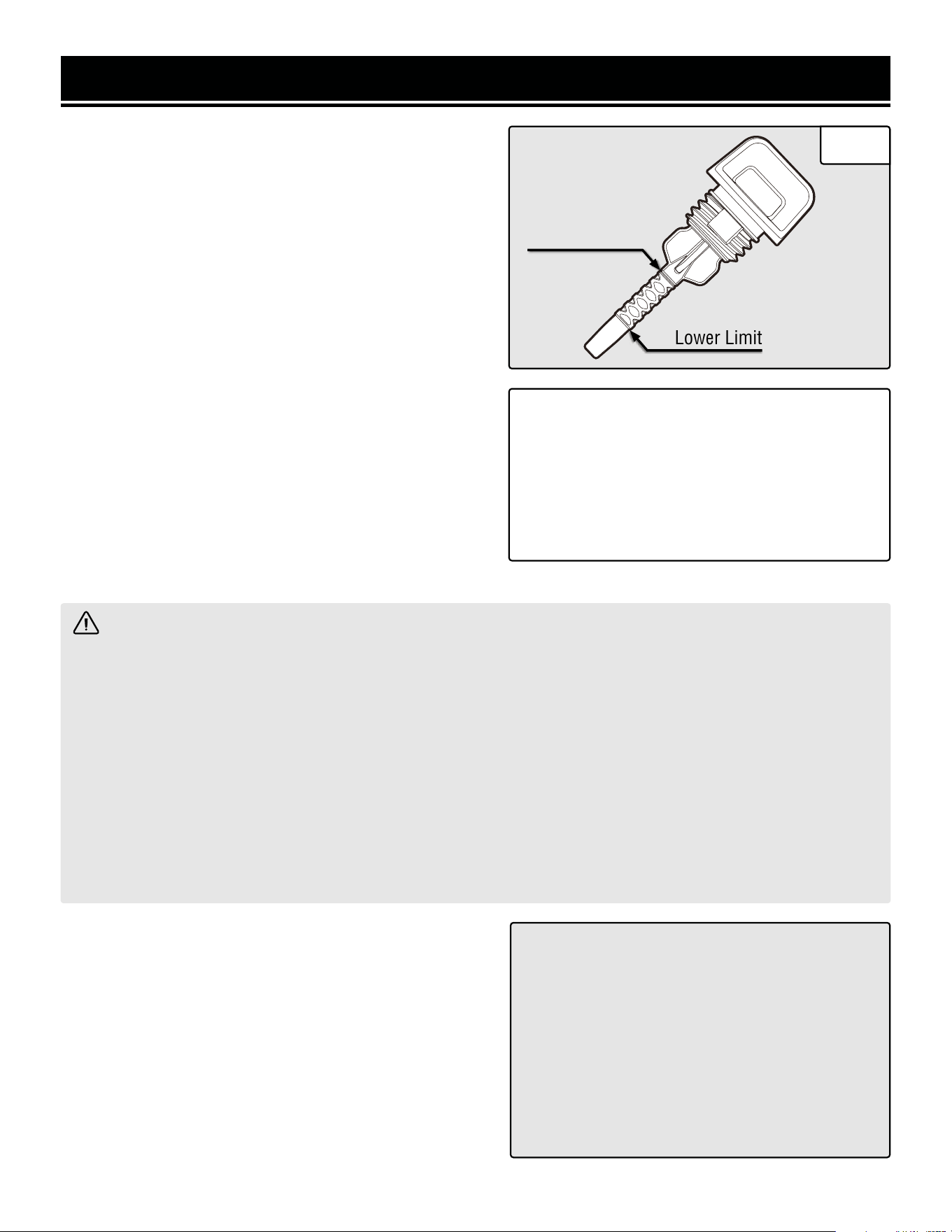
GENERATOR PREPARATION
Lower Limit
Upper Limit
TO CHECK OIL LEVEL (before every subsequent start):
1. Place the generator on a level surface. Make sure the
engine is OFF before adding or checking oil.
2. Remove and wipe the dipstick with a clean rag.
3. Insert the dipstick into the oil fill without screwing it in.
Remove the dipstick to check the oil mark.
4. If the oil mark covers less than one half of the dipstick,
slowly add oil until the oil mark reaches the top of the dip-
stick (or when you can see the oil coming halfway up the
oil fill threads). See Fig. 6.
OIL LEVEL SHUTDOWN
To protect the unit from damage, the generator is equipped
with a low-oil-pressure shutoff that will automatically shut
down the engine when the oil level is too low. The oil level
of the engine should be checked before each start to ensure
that the engine crankcase contains sufficient lubricant.
STEP 2 - ADD/CHECK FUEL
TIP: Your WEN generator is compatible with the
WEN 55201 Magnetic Oil Dipstick (not included),
available for purchase at wenproducts.com. The
dipstick’s industrial-strength magnetic tip will
collect metal shavings from your generator’s oil
tank to help preserve the engine and extend your
generator’s lifespan.
WARNING: RISK OF EXPLOSION. HIGHLY FLAMMABLE: This generator may emit highly flammable and
explosive gasoline vapors, which can cause severe burns or even death, if ignited. A nearby open flame can lead
to explosion even if not directly in contact with gasoline.
• Do not operate near open flame, heat, or any other ignition source. Do not smoke near the generator.
• Always operate on a firm, level surface.
• Always turn generator off before refueling. Allow generator to cool for at least 2 minutes before removing
fuel cap. Loosen cap slowly to relieve pressure in tank.
• Do not overfill fuel tank. Gasoline may expand during operation. Do not fill to the top of the tank. Allow for
expansion. Always check for spilled fuel before operating.
• If fuel spills, move the generator at least 30 feet away from the spill and wipe clean any spilled fuel before
starting the engine.
• Empty fuel tank before storing or transporting the generator.
ONLY use fresh (within 30 days from purchase), lead-free
gasoline with a minimum of 87 octane rating. The genera-
tor performs best with ethanol-free gasoline. DO NOT use
gasoline with over 10% ethanol.
The capacity of the fuel tank is 1.85 US gallons (7L). Do
not mix oil with gasoline.
Follow the instructions on the next page to add gasoline.
IMPORTANT:
• Avoid getting dirt or water into the fuel tank.
• Keep gasoline away from sparks, open flames,
pilot lights, heat, and other sources of ignition.
• Gasoline can age in the tank and make starting
difficult. Never store the generator for more
than 2 months with fuel in the tank.
• Never use an oil/gasoline mixture.
• Never use old gasoline.
Fig. 6
14
15
GENERATOR PREPARATION
Fig. 8
TO ADD GASOLINE:
1. Place the generator on a level surface. Make sure the
engine is OFF before adding or checking the fuel.
2. Unscrew the fuel cap (Fig. 7) and set it aside. The fuel
cap may be tight and hard to unscrew.
3. Slowly add unleaded gasoline to the fuel tank. Be careful
not to overfill. Reinstall fuel cap and wipe clean any spilled
gasoline with a dry cloth.
NOTE: Do not fill the fuel tank to the very top. If you do
so, gasoline will expand and spill during use, even with
the fuel cap in place.
TO CHECK GAS LEVEL (before every subsequent start):
1. Before starting the generator, check the fuel gauge (Fig.
7) to see if there is sufficient fuel inside the tank:
• E = Empty
• F = Full
2. If the tank is empty add gasoline to the gas tank. See
above section, "To Add Gasoline".
STEP 3 - GROUND THE GENERATOR
To reduce the risk of electric shock and to maximize safety,
the generator should be properly grounded.
1. Attach one end of the grounding wire to the grounding
nut (Fig. 8). Tighten the nut to secure the grounding wire.
2. Connect the other end of the grounding wire to a copper,
brass, or steel-grounding rod that is driven into the earth.
Fuel Gauge
Fig. 7
Fuel CapFuel Cap
WARNING! Failure to properly ground the
generator increases your risk of electric shock.
NOTE: Grounding wire and grounding rods
are not included with the generator. A general-
ly acceptable grounding wire is a No. 12 AWG
(American Wire Gauge) stranded copper wire.
Grounding codes can vary by location. Contact a
local electrician to check the area codes.
Grounding
Nut
1716
CAUTION! Disconnect all electrical loads from the generator before attempting to start it.
Before starting the generator, make sure you have read and performed the steps in the “Generator Preparation”
section of this manual, pages 14-16. If you are unsure about how to perform any of the steps in this manual please
call 1-847-429-9263 (M-F 8-5 CST) for customer service.
To maximize safety, ALWAYS ground the generator before using it. Refer to "Step 3 - Ground The Generator" on
page 15.
Use a ground fault circuit interrupter (GFCI) in highly conductive areas such as metal decking or steel work. GFCIs
are available in-line with some extension cords.
STARTING YOUR GENERATOR
DANGER: CARBON MONOXIDE
Using a generator indoors CAN KILL YOU IN MINUTES. Generator exhaust contains carbon monoxide (CO).
This is a poison gas you cannot see or smell. If you can smell the generator exhaust, you are breathing CO. But
even if you cannot smell the exhaust, you could be breathing CO.
NEVER use a generator inside homes, garages, crawl spaces, or other partially enclosed areas. Deadly levels
of carbon monoxide can build up in these areas. Using a fan or opening windows and doors does NOT supply
enough fresh air. ONLY use a generator outside and far away from windows, doors, and vents. These openings
can pull in generator exhaust.
Even if you use a generator correctly, CO may leak into the home. ALWAYS use a battery-powered or battery-
backup CO alarm in the home. If you start to feel sick, dizzy, or weak after the generator has been running, move
to fresh air RIGHT AWAY. See a doctor. You may have carbon monoxide poisoning.
WARNING: The exhaust from this product contains chemicals known to the State of California to cause
cancer, birth defects, or other reproductive harm.
WARNING: Do not operate generator near open flame or flammable materials This generator may emit
highly flammable and explosive gasoline vapors, which can cause severe burns or even death if ignited. A
nearby open flame can lead to explosion even if it isn’t directly in contact with gasoline. Do not smoke near the
generator.
WARNING: This generator produces powerful voltage, which can result in electrocution.
WARNING: Do not use in rainy or wet conditions. Do not touch bare wires or receptacles (outlets). Do not
allow children or non-qualified persons to operate.
WARNING: Generator should only be connected to electrical devices, either directly or with an extension
cord. NEVER connect to a building electrical system without a qualified electrician and connected to a transfer
switch as a separately derived system. Such connections must comply with local electrical laws and codes.
Failure to comply can create a back-feed, which may result in serious injury or death to utility workers.
Follow the instructions on the next page to start your generator.
1716
BEFORE STARTING THE GENERATOR
1. Verify that the generator is outside on a dry, level surface. Allow at least two feet of clearance on all sides of the
generator.
2. To maximize safety, check that the generator is properly grounded. Refer to "Step 3 - Ground The Generator" on
page 15.
3. Check that there is a sufficient level of oil in the crankcase. Add oil if necessary. Refer to "Step 1 - Add/Check
Oil" on page 13.
4. Check that there is a sufficient level of fuel in the fuel tank. Add gas if necessary. Refer to "Step 2 - Add/Check
Fuel" on page 14.
5. Make sure all electrical devices are unplugged from the generator during ignition. Otherwise it will be difficult
for the engine to start.
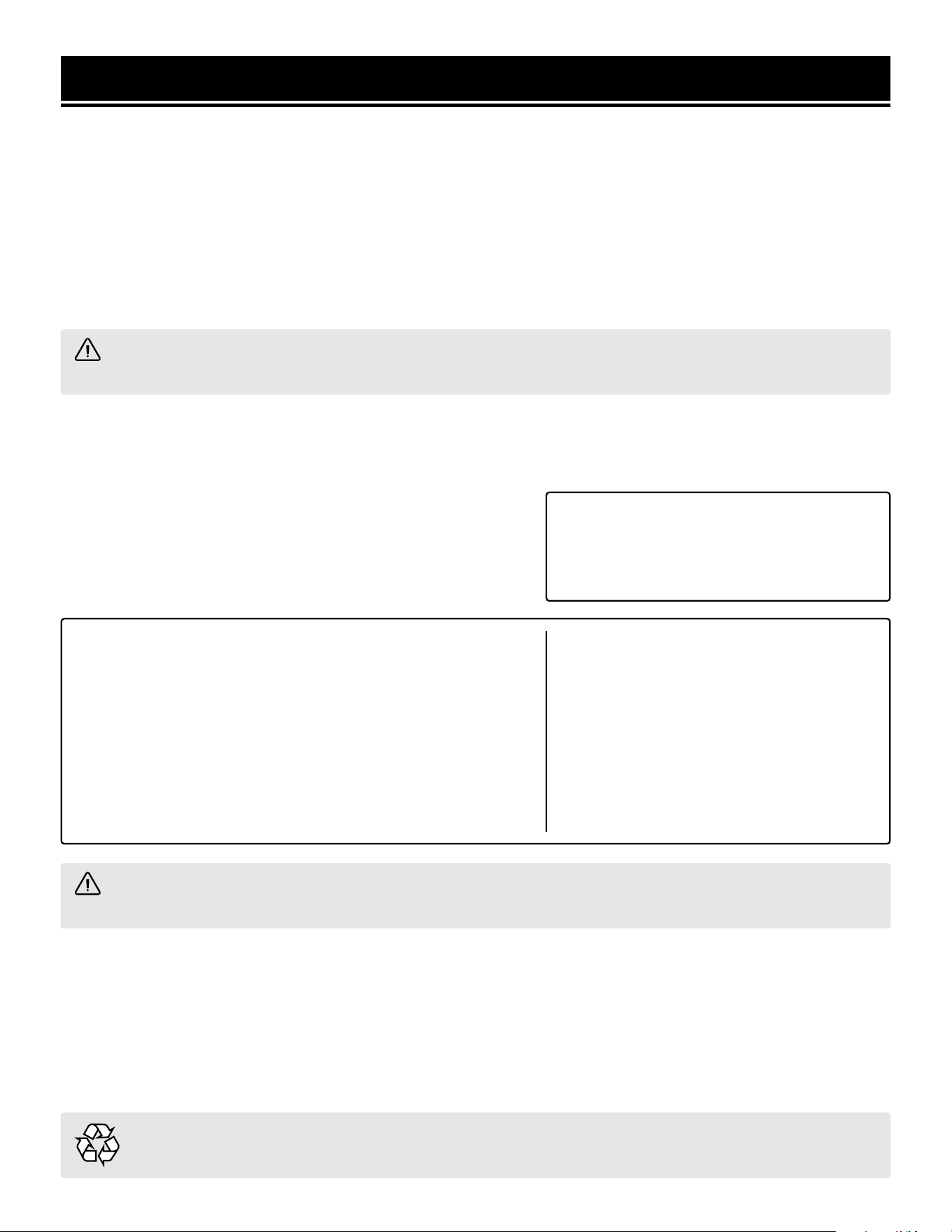
STARTING YOUR GENERATOR
FUEL VALVE
OFF
ON
Fig. 9
NOTE: In case you have had repeated failed attempts
to start the engine, please consult the troubleshooting
guide before attempting to start the generator. If prob-
lems persist please call 1-847-429-9263, M-F 8-5 CST.
STARTING THE GENERATOR
1. Turn the fuel valve to the ON position (Fig. 9).
2. Pull the choke button out to the CLOSE/START position
(Fig. 10).
3. Flip the engine switch (page 12) to the RUN position.
4. Pull on the recoil starter handle (page 11) slowly until
a slight resistance is felt, then pull quickly to start the en-
gine. Return cord gently into the recoil starter. Never allow
the cord to snap back.
5. If engine fails to start, repeat this step.
6. Once the engine has started, slowly push the choke but-
ton into the OPEN/RUN position (Fig. 10).
7. Allow the engine to run for several minutes before at-
tempting to connect any electrical devices. This allows the
generator to stabilize its speed and temperature. Follow
the instructions in the next section for properly connecting
your electrical devices.
Fig. 10
ENGINE BREAK-IN PROCEDURE
The procedure below should be followed when you receive your generator in order to prolong the engine’s service
life. This procedure helps to seat the piston rings properly in the cylinder, and will reduce overall wear on the en-
gine.
For the first 8 hours of operation, vary the load, but keep it at or below 50% of the generator’s rated wattage, if
possible. If your generator is equipped with an Eco-mode switch (only applicable for certain inverter generators),
engage Eco-mode periodically during the first 8 hours. After the first 8 hours, change the oil, then change it again
after the first 25 hours. You may run the generator at full load after the 8-hour oil change. Refer to the Recom-
mended Maintenance Schedule in Table 4 for the full maintenance schedule.
1918
USING YOUR GENERATOR
CALCULATING THE WATTAGE OF YOUR DEVICE(S)
Connect electrical devices running on AC current according to their wattage requirements. Calculate the total run-
ning wattage and starting wattage of the device(s) you wish to connect, and MAKE SURE that they are within the
capacity of your generator and the capacity of each individual outlet.
Generator
Wattage
Capacity
GENERATOR RUNNING (RATED) WATTS GENERATOR STARTING (SURGE) WATTS
3500W 4000W
What this means:
The generator can produce a maximum of
3500W on a continuous basis to supply on-
going power to your electronic devices.
NOTE: Also check the rated amperage for
each outlet and make sure not to overload
the individual outlets.
What this means:
Some devices such as box fans require
short bursts of extra power in addition to
the rated wattage listed by the device to start
their motors.
The generator can produce a maximum
wattage of 4000W for a short period of time
(seconds) to cover the extra starting power
required by your electronic devices.
Electronic
Device
Wattage
Calculation
Find the wattage information of each device you plan to connect. The information should
be listed on the device or in its instruction manual, or you may refer to page 19, Table
2 - Estimated Wattages of Common Electrical Appliances.
The wattage can be calculated using this equation: Watts = Volts x Amperes
To calculate the total running watts of your
devices:
+ Add up the running wattages of all the
device(s) you plan to connect.
= The total running (rated) wattage.
This wattage should NOT exceed the run-
ning wattage of 3500W.
It is recommended to maintain a load at or
below 3150W (90% of the rated output) to
ensure steady voltage output and to prolong
the generator’s lifespan.
To calculate the total starting watts of your
devices:
+ Add up the total running wattage of all the
device(s) you plan to connect.
+ Add the single highest ADDITIONAL start-
ing wattage out of the device(s) you plan to
connect.
= The total starting (surge) wattage.
This wattage should NOT exceed the starting
wattage of 4000W.
If any of either of the total calculated running watts or starting watts is higher than the capac-
ity of your generator, adjust the load until both wattage requirements are met. Otherwise you
will overload the generator, and cause damage to the engine and your electrical device(s).
Table 1 - How to Calculate Wattages
1918
USING YOUR GENERATOR
CALCULATING THE WATTAGE OF YOUR DEVICE(S) - CONTINUED
The chart below serves as a reference for the estimated wattage requirements of common electrical devices. How-
ever, do not solely rely on this chart - all electronics and appliances are built differently. Always check the wattage
listed on the electrical device before consulting this chart.
Tool or Appliance Rated (Running) Watts Surge (Starting) Watts
Hot Plate 2500 0
Saw - Radial Arm 2000 2000
Electric Stove (Each Element) 1500-2800 0
Saw - Circular 1500 1500
Air Compressor (1 HP) 1500 3000
Window Air Conditioner 1200 1800
Saw - Miter 1200 1200
Microwave 1000 0
Well Water Pump 1000 1000
Sump Pump 800 1200
Refrigerator Freezer 800 1200
Furnace Blower 800 1300
Computer 800 0
Electric Drill 600 900
Television 500 0
Deep Freezer 500 500
Garage Door Opener 480 0
Stereo 400 0
Box Fan 300 600
Clock Radio 300 0
Security System 180 0
DVD Player / VCR 100 0
Common Light Bulb 75 0
Table 2 - Estimated Wattages of Common Electrical Appliances
NOTE: Become familiar with the functions and capacity of each component on the control panel before con-
necting electrical devices. See page 12 for more information about the components of the control panel. Do
not overload generator or individual panel receptacles. Do not connect 50Hz or 3-phase loads to the generator.

2120
USING YOUR GENERATOR
CONNECTING ELECTRICAL DEVICES
1. Before connecting electrical devices, allow the generator to run for a few minutes to stabilize the speed and
voltage output.
2. Select the device with the highest wattage, and make sure it is turned off. Plug the device into the matching
generator outlet and then turn the device on. Allow the engine to stabilize.
3. Repeat step 2 to plug in each additional device. Do not attempt to plug in or start multiple devices at the same
time.
ECO-MODE SWITCH
This generator is equipped with an Eco-Mode Idle Control Switch (page 12). Engaging this switch allows the
system to regulate the engine speed and automatically adjust its fuel consumption to match the required load.
When the electrical load changes, the generator engine will automatically speed up and slow down as needed. This
reduces fuel consumption and noise levels, while extending runtime and engine’s lifespan.
Keep this switch engaged ONLY when the power load requirement is less than 2400W (75% of the rated watts). Do
not engage the Eco-Mode Switch when the total load is more than 2400W. The generator engine must run at full
speed to supply power for anything over 2400W.
PARALLEL OPERATION
The parallel connection ports (page 12) allow you to connect two WEN generators to increase the total available
electrical power. The WEN Parallel Connection Kit can be purchased from wenproducts.com. Follow the instruc-
tions included with your parallel connection kit for proper installation and operation.
CIRCUIT BREAKER
The 20A AC circuit breaker will activate when the load on the NEMA 5-20R outlets exceeds 20A. When the circuit
breaker activates, turn off and disconnect the device from its respective outlet, and press the circuit breaker to
reset.
IN CASE OF OVERLOAD
If your generator becomes overloaded from too much drawn wattage, the overload light (red) on the control panel
will light up. Follow the instructions below when an overload occurs:
• When you’re close to overloading the generator, the overload light will start to flash. Reduce the load by turn-
ing off and disconnecting your electronic device(s) until the overload light turns off. Then you may continue to
operate your generator.
• When you’ve overloaded the generator, the overload light will stay on and the overload reset button (page
12) will activate to cut off the output in 3 to 16 seconds, depending on the load. Reduce the load by turning
off and disconnecting your electrical device(s) until the overload light turns off. Wait about five minutes and
then press the activated reset button to reset the circuit. If no power is produced after resetting, turn off and
disconnect all electrical devices and restart your generator.
• The pattern in which the overload light blinks gives diagnostic information about the problem. Refer to the
chart on the next page.
2120
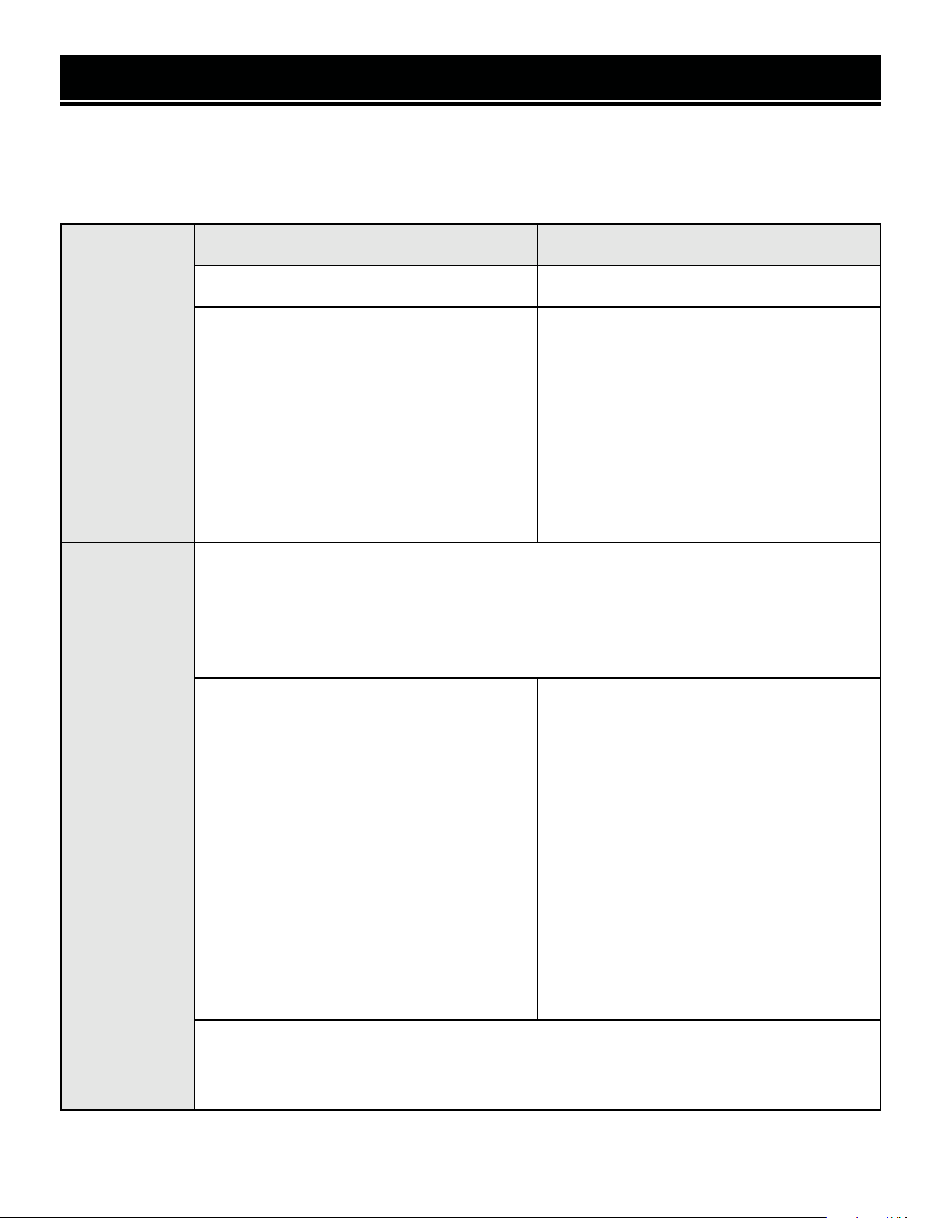
LIGHT
MEANING RESOLUTION
GREEN
(POWER INDICATOR)
RED
(OVERLOAD)
ON OFF Generator output is normal. No action needed.
ON Flashing continuously Generator is exceeding rated output. Reduce load on generator.
OFF Flashes 1x, repeating
every 3 sec
Voltage at alternator is too low. No
electrical output.
Check for loose connections. Call
1-847-429-9263 for assistance.
OFF Flashes 2x, repeating
every 3 sec
Engine speed is too low. No electrical
output.
Check carburetor and stepper motor.
Ensure Eco-Mode is OFF. Have genera-
tor serviced; call 1-847-429-9263 for
assistance.
OFF Flashes 3x, repeating
every 3 sec
Inverter temperature is too high. No
electrical output.
Turn generator off and let it cool down
fully (1 – 2 hours) before restarting.
OFF Flashes 5x, repeating
every 3 sec
Voltage at alternator is too high. No
electrical output.
Have generator serviced; call 1-847-
429-9263 for assistance.
OFF Flashes 6x, repeating
every 3 sec
Generator has exceeded rated output
and cut off power to protect itself. No
electrical output.
Turn OFF and disconnect loads. Press
RESET button on panel. Reduce load
on generator.
USING YOUR GENERATOR
Table 3 - Power Cord Requirement Guide*NR = Not Recommended
Device Requirements Max. Cord Length (ft) by Wire Gauge
Amps Watts
(120V)
Watts (240V) #8 wire #10 wire #12 wire #14 wire #16 wire
2.5 300 600 NR NR NR 375 250
5 600 1200 NR NR 300 200 125
7.5 900 1800 NR 350 200 125 100
10 1200 2400 NR 250 150 100 50
15 1800 3600 NR 150 100 65 NR
20 2400 4800 175 125 75 50 NR
25 3000 6000 150 100 60 NR NR
30 3600 7200 125 65 NR NR NR
40 4800 9600 90 NR NR NR NR
WARNING! Generator should only be connected to electrical devices, either directly or with an extension
cord. NEVER CONNECT TO A BUILDING ELECTRICAL SYSTEM without a qualified electrician and connected to
a transfer switch as a separately derived system. Such connections must comply with local electrical laws and
codes. Failure to comply can create a back-feed, which may result in serious injury or death to utility workers.
NOTE: For power outages, permanently installed, stationary generators are better suited for providing backup
power to your home. Even a properly connected portable generator can become overloaded. This may result
in overheating or stressing the machine’s components, possibly leading to generator failure.
SOME NOTES ABOUT POWER CORDS
Refer to the following chart in determining the necessary gauge extension cord for each of your devices. Round up
to the higher amperage in the chart to maximize safety.
2322
USING YOUR GENERATOR
CO SENSOR INFORMATION
The CO Watchdog carbon monoxide monitoring system
(Fig. 11 - 1) measures the accumulation of poisonous CO
gas while the generator is running. If the level of CO gas
gets too high, the CO Watchdog system will automatically
shut down the generator. This system is not a substitute
for an indoor CO alarm.
Whenever the CO Watchdog system shuts down the gen-
erator, the LED on the generator control panel (Fig. 11 - 1)
will blink red for at least 5 minutes after the generator is
shut down. If you notice that the LED is blinking red, va-
cate the area immediately. Go to an open, outdoor area.
Ventilate the area around the generator thoroughly before
returning. Let the generator stay shut down for a few min-
utes before restarting the engine. This should allow carbon
monoxide to dissipate from the area. If you restart the gen-
erator and the CO Watchdog detects that CO levels are still
too high, it will shut down the generator again. If CO levels
are low enough, the generator will run normally.
1
Ensure that the generator is located in an open outdoor area, with the exhaust pointing away from occupied struc-
tures, and pointing away from the prevailing winds, such that those winds do not blow engine exhaust towards the
sensor module. If anyone experiences dizziness, headaches, nausea, fatigue, or other symptoms of CO poisoning,
get to fresh air immediately and seek the attention of a qualified medical professional. Follow all other directions in
this manual regarding the connection and disconnection of electrical devices when starting or shutting down the
generator.
When starting the generator, the CO Watchdog LED on the panel may flash. This indicates that the system is run-
ning a self-test procedure, and does not indicate a problem.
If the CO Watchdog LED on the panel is yellow, a system error has occurred, or the CO sensor has reached the
end of its life. Contact WEN customer service (1-847-429-9263, M – F 8 – 5 CST, or techsupport@wenproducts.
com) for assistance.
When operating your generator, please note the following:
• The CO Watchdog does not discriminate in its input; any source of carbon monoxide in the area around the
generator could cause it to activate. If the CO Watchdog LED is blinking red, safety measures should be taken im-
mediately.
• Tampering with, disconnecting, or bypassing the CO sensor could cause hazardous conditions, including but not
necessarily limited to injury or death, and will void your warranty. The generator will not run with the CO sensor
disconnected or bypassed, or if the CO sensor indicates an error.
• The CO sensor has a lifetime of about 7 years, and is capable of monitoring its lifetime. If your generator shows
an error light several years after purchase, it may be time to replace the CO sensor. Contact WEN customer service
for assistance.
NOTE: if the generator is oriented so that the
engine exhaust is blown towards the CO sensor,
the generator may shut down.
Fig. 11
2322
SHUTTING OFF YOUR GENERATOR
CAUTION! Unplugging running devices can cause damage to the generator. Never stop the engine with
electrical devices connected and running.
WARNING! Allow the generator to cool down before touching areas that become hot during use.
CAUTION! Allowing gasoline to sit in the fuel tank for long periods of time can make it difficult to start the gen-
erator in the future. Never store the generator for extended periods of time (over 2 months) with fuel in the fuel
tank. Refer to "Storing The Generator" on page 29.
IMPORTANT: Always ensure that the fuel valve and the engine switch are in the OFF position when the generator
is not in use.
MANUAL SHUTOFF
1. Turn off all electrical devices prior to unplugging them
from the generator. Unplugging running devices can cause
damage to the generator. Never start or stop the generator
with electrical devices plugged in or turned on.
2. Let engine run at no-load for several minutes to stabilize
internal temperatures of engine and generator.
3. Turn the fuel valve to the OFF position (Fig. 12). Let the
generator run until the fuel is used up.
4. Flip the engine switch (page 12) to the STOP position.
5. Drain the carburetor. Refer to "Draining The Carburetor"
on page 26.
NOTE: If for some reason (e.g. refueling, moving the generator, etc.) you need to shut down the generator
quickly, simply flip the engine switch to STOP. However, doing this will allow fuel to remain in the carburetor,
and will lead to problems if the carburetor is not drained after use.
OFF
ON
FUEL VALVE
Fig. 12
2524
MAINTENANCE
WARNING! Never perform maintenance operations while the generator is running. Before maintaining or
servicing the generator, turn OFF the generator, disconnect all devices and allow the generator to cool down.
NOTE: Failure to properly maintain the generator will void the warranty.
RECOMMENDED MAINTENANCE SCHEDULE
Proper routine maintenance of the generator will help prolong the life of the machine. Please perform maintenance
checks and operations according to the maintenance schedule below, Table 4. If there are any questions about the
maintenance procedures listed in this manual, please contact customer service at 1-847-429-9263 (M-F 8-5 CST),
or email [email protected].
IMPORTANT GENERATOR MAINTENANCE TIPS:
• Drain your carburetor after each use and before storage to prevent it from clogging.
• Do not store the generator with fuel inside the tank for more than 2 months - the fuel will go bad.
• Run the generator for 20 to 30 minutes every month to maximize its lifespan.
Recommended
Maintenance Schedule
Every 8
Hours or
Daily
Every 25
Hours
Every 3
Months or
50 Hours
Every 6
Months or
100 Hours
Before
Storage
As
Necessary
Engine Oil
Check Level x
Replace x** x** x* x
Air Filter
Check x*
Clean x*
Spark Plug
Check/Clean/
Regap
x
Change x x
Fuel
Check Level x
Drain x x
Carburetor Drain x x
Spark
Arrestor
Check/Clean x
Table 4 - Recommended Maintenance Schedule* Clean/change more often under dusty conditions or operat-
ing under heavy load.
** Change the oil after the first 8 hours of operation, after the
first 25 hours of operation, and every 50 hours after that.
2524
MAINTENANCE
WARNING! Never clean the generator when it is running! Never clean with a bucket of water or a hose.
Water can get inside the working parts of the generator and cause corrosion or a short circuit.
CLEANING YOUR GENERATOR
Keep the generator clean to prevent improper operation or machine damage from dirt and debris. Inspect all ven-
tilation openings on the generator. These openings must be kept clean and unobstructed.
If the generator becomes dirty, use a damp cloth to wipe exterior surfaces. Use a soft bristle brush to loosen dirt
and oil and use a vacuum to pick up loose dirt. Use low pressure air (not to exceed 25 PSI) to blow away dirt.
CHECKING/ADDING OIL
Check the oil level before each use and every 8 hours of operation (refer to page 24, Table 4). The oil capacity
of the generator engine is 17.0 fl. oz. (0.5 L). Add oil when the oil level is low. For the proper type and weight of
oil refer to page 13, Fig. 3. This is a critical step for proper engine starting. The generator is equipped with a with
low-oil shut down to protect it from running without oil.
To check the oil level and/or add oil refer to "Step 1 - Add/Check Oil" on page 13.
TIP: Your WEN generator is compatible with the WEN 55201 Magnetic Oil Dipstick (not included), available for
purchase at wenproducts.com. The dipstick’s industrial-strength magnetic tip will collect metal shavings from
your generator’s oil tank to help preserve the engine and extend your generator’s lifespan.
DRAINING/CHANGING OIL
Change the oil according to the Recommended Maintenance Schedule (refer to page 24, Table 4). Change
the oil more often if operating under heavy load or high ambient temperatures. It is also necessary to drain the oil
from the crankcase if it has become contaminated with water or dirt. Changing the oil when the engine is warm
allows for complete drainage.
1. Place generator on a level, elevated platform. Prepare
an approved oil-storage container underneath the oil drain
bolt next to the oil dipstick to catch the oil as it drains. See
Fig. 13. NOTE: To avoid possible fuel spills from the car-
buretor bowl, drain the carburetor (refer to "Draining The
Carburetor" on page 26) before draining the oil.
2. Unscrew the oil drain bolt and allow oil to drain from the
engine completely.
3. Reinstall the oil drain bolt and tighten it securely. Wipe
clean any oil spillage.
4. To add new oil, refer to "Step 1 - Add/Check Oil" on page
13.
DipstickDipstick
Oil Drain BoltOil Drain Bolt
NOTE: Never dispose of used engine oil in the trash or down a drain. Please call a local recycling center or auto
garage to arrange proper oil disposal.
Fig. 13
2726
MAINTENANCE
WARNING! Running the engine with a dirty, damaged or missing air filter element can result in danger to
the operator and cause the engine to wear out prematurely.
NOTE: Make sure to drain your carburetor before
storing the generator for long periods of time.
DRAINING THE CARBURETOR
Drain the carburetor after every use and before storing
the generator (refer to page 24, Table 4). Draining the
carburetor can help prevent build-up and blockages caused
by stagnant fuel inside of the carburetor.
1. Prepare an approved gasoline-storage container under
the carburetor to collect the drained fuel.
2. The carburetor can be accessed from the backside of
the generator between the engine and the air filter. To drain
the carburetor, open up the carburetor drain screw with a
Phillips-head screwdriver (not included) and drain out any
gasoline that has built up inside. See Fig. 14.
3. Once the fuel has drained, close the drain screw.
INSPECTING/CLEANING THE AIR FILTER
Inspect and clean the air filter every 50 hours of operation (refer to page 24, Table 4). Routine maintenance of
the air filter helps maintain proper airflow to the carburetor. Occasionally check that the air filter is free of excessive
dirt. Clean air filter more frequently in dirty or dusty conditions.
1. Remove the air filter cover by unscrewing the cover lock
knob at the bottom of the air filter cover. See Fig. 15.
2. Remove the foam, sponge-like air filter element from the
casing. Wipe excessive oil and any dirt from inside of the
air filter casing.
3. Check the foam, sponge-like air filter element.
a) Good elements can be washed in soapy water. Dry
the element in clean cloth (do not twist it). Add a few
drops of engine oil to the air filter element and spread it
evenly. A small amount of oil left in the element is normal
and necessary for the engine to work properly.
b) Damaged elements should be replaced with a new
one. Replacement air filters can be purchased from
wenproducts.com by searching part number
GN400i-1002.
4. Reinstall the air filter element and air filter cover.
Air FilterAir Filter
CoverCover
CoverCover
LockLock
Drain ScrewDrain Screw
Fig. 15
Fig. 14
2726
MAINTENANCE
INSPECTING/CLEANING THE SPARK ARRESTOR
Inspect and clean the spark arrestor every 100 hours of
operation (refer to page 24, Table 4). The spark arrestor
is located outside the muffler, which gets very hot during
operation. Allow the engine to cool completely before ser-
vicing the spark arrestor.
1. Remove the Phillips-head screw that secures the spark
arrestor to the muffler. See Fig. 16.
2. Remove the spark arrestor screen.
3. Carefully clean and remove the carbon deposits from the
spark arrestor screen with a wire brush. Replace the spark
arrestor if it is damaged. Replacement spark arrestors can
be purchased from wenproducts.com by searching the
part number GN400i-1101.1.
Spark Plug Spark Plug
BootBoot
Spark ArrestorSpark Arrestor
AssemblyAssembly
4. Reinstall the spark arrestor in the muffler and secure it in place with the screws.
SPARK PLUG MAINTENANCE
Inspect and change the spark plug every 100 hours of operation (refer to page 24, Table 4). The spark plug is
important for proper engine operation. Check the spark plug regularly to maintain proper engine operation. A good
spark plug should be intact, free of deposits, and properly gapped.
1. Gently pull on the spark plug boot to remove it (Fig. 16). Be careful not to tear insulation or wire.
2. Use the included spark plug wrench (page 9, slide the handle into the hole on the wrench) to unscrew the
spark plug from the engine. Remove the spark plug from the engine. TIP: There is limited space for the wrench to
turn. Use both rows of holes in the spark plug wrench to gain leverage to loosen the plug.
3. Visually inspect the spark plug. If it is cracked or chipped, or if the electrodes are worn or burned, discard it and
replace with a new spark plug. We recommend replacing it with an F6RTC spark plug. These can be purchased
from wenproducts.com by searching part number 56310i-0104.
4. If re-using the spark plug, use a wire brush to clean any dirt from around the spark plug base, then re-gap the
spark plug.
Instructions continue on the next page.
Fig. 16
2928
MAINTENANCE
FUEL VALVE
OFF
ON
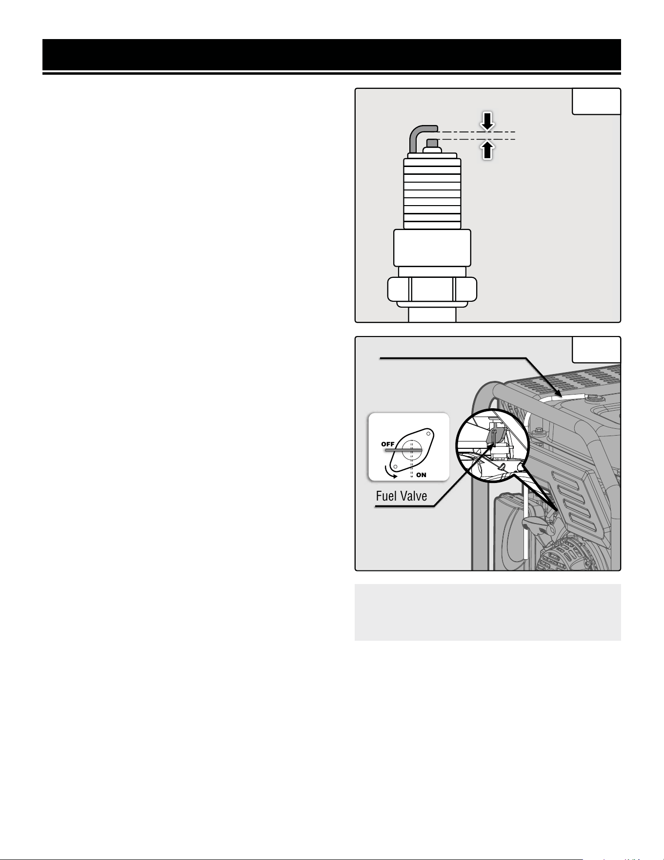
5. Measure the plug gap with a spark plug gap gauge. The
gap should be 0.7 to 0.8 mm (0.028-0.031 in). Carefully
adjust the gap if necessary. See Fig. 17.
6. Screw the spark plug back into the spark plug hole us-
ing the spark plug wrench. Do not over-tighten spark plug.
Recommended tightening of the spark plug is ½ to ¾ of a
turn (15 ft-lb torque/20.33 Nm) after the spark plug gasket
contacts the spark plug hole.
7. Reinstall the spark plug boot over the spark plug.
DRAINING THE FUEL TANK
Drain and clean the fuel tank each year, or before storing
the generator for longer than two months.
1. Prepare an approved gasoline-storage container to col-
lect the drained fuel. Place it near the fuel valve (Fig. 18).
2. Turn the fuel valve to the OFF position.
3. Locate the fuel line between the fuel valve and the carbu-
retor (Fig. 18). Disconnect the fuel line from the fuel valve.
See Fig. 17. NOTE: A small amount of fuel may leak from
the fuel line during removal.
4. Place a funnel below the fuel valve opening, and direct
the other end of the funnel over the prepared container.
5. Turn the fuel valve to the ON position to start draining
the fuel from the fuel valve opening. NOTE: The draining
process may take a few hours, depending on the amount of
fuel in your gas tank.
6. Once the fuel is completely drained, turn the fuel valve to
the OFF position.
7. Start and run the engine until the fuel runs out.
8. Drain the carburetor. Refer to "Draining The Carburetor"
on page 26.
CAUTION! Store the emptied gasoline in a suit-
able place. Never store fuel for more than 2
months.
0.7 - 0.8mm
Fuel LineFuel Line
Fuel ValveFuel Valve
Fig. 17
Fig. 18
2928
TRANSPORTATION & STORAGE
WARNING! Avoid direct sunlight inside a vehicle. If the generator is left in an enclosed vehicle for many
hours, the high temperature could cause the fuel to vaporize and result in a possible explosion.
TRANSPORTING THE GENERATOR
To prevent fuel spillage when transporting, be sure to perform the following:
1. Tighten the fuel cap and turn the fuel valve to the OFF position.
2. Flip the engine switch to the STOP position.
3. Drain the fuel tank if possible. Refer to "Draining The Fuel Tank" on page 28.
4. Keep the generator upright. Never place the generator on its side or upside down - doing so could damage the
internal components of the generator and make it difficult to start.
STORING THE GENERATOR
Shut off the generator and allow the unit to cool to room temperature before storing it. NEVER place any type of
storage cover on the generator while it is still hot. Do not obstruct any ventilation openings.
For Short Periods (30 to 60 Days):
• Drain the carburetor. Refer to "Draining The Carburetor" on
page 26.
• Add fuel stabilizer: Follow the suggested portions and
instructions of your preferred stabilizer. Run the engine for
15 to 20 minutes, allowing the fuel stabilizer to mix with the
gasoline and circulate through the carburetor, and then top
off with fuel. Filling the fuel tank full reduces the amount of
air in the tank and helps fight deterioration of fuel.
For Extended Periods (Over 60 Days):
• Drain the fuel tank and carburetor.
Refer to "Draining The Fuel Tank"
on page 28, and "Draining The
Carburetor" on page 26.
• Never store generator with fuel in the
tank for more than two months.
• Change the engine oil. Refer to
"Checking/Adding Oil" on page 25.
WARNING! Store the generator upright in a cool and dry location, away from sources of heat, open flames,
sparks or pilot lights.
Follow the procedures below for properly storing your generator.
We highly recommend running your generator once a month for
20 to 30 minutes. Plug in a small load in to ensure there is proper
power output.
Please recycle the packaging and electronic components where facilities exist. Please contact your
local auto garage or recycling facility to properly dispose of oil/fuel.
TIP: Your WEN generator is compatible
with the WEN 56310iC Generator Cover
(not included). It is available for purchase
at wenproducts.com.
PRODUCT DISPOSAL
Do not dispose of used generator or parts with your household waste. This product contains electrical or electronic
components that should be recycled. Please take this product to your local recycling facility for responsible dis-
posal to minimize its environmental impact.
Do not dispose of used oil or fuel in the trash or down a drain. Please contact your local recycling center or auto
garage to arrange proper oil/fuel disposal.
3130
TROUBLESHOOTING GUIDE
PROBLEM POSSIBLE CAUSE SOLUTION
Engine will not start.
1. Engine switch is set to STOP. 1. Set engine switch to RUN.
2. Fuel valve is turned to OFF. 2. Turn fuel valve to ON.
3. Oil is low.
3. Add or replace oil. Refer to "Step 1 - Add/
Check Oil" on page 13.
4. Engine is out of fuel.
4. Add fuel. Refer to "Step 2 - Add/Check Fuel"
on page 14.
5. Engine is filled with
contaminated or old fuel.
5. Drain the fuel in the tank and fill with fresh
fuel. Refer to "Draining The Fuel Tank" on page
28.
6. Spark plug is dirty or broken.
6. Clean or replace the spark plug. Refer to
"Spark Plug Maintenance" on page 27.
7. Carburetor is air locked.
7. Shut off the fuel valve. Remove the bolt
from the bottom of the carburetor. Take off the
carburetor bowl to allow it to reset. Replace
carburetor bowl and reinstall the bolt.
8. Ghost in the generator. 8. Persuade the ghost to leave.
Engine runs but there is
no electrical output.
1. Circuit breaker has been
tripped due to overload.
1. Turn off and unplug electrical device(s). Wait
5 minutes, then press the circuit breaker to
reset. Check the total wattage of the devices
and reduce the load if it exceeds the capacity of
the generator. Then plug the loads back in one
by one.
2. Bad connecting cords/wires.
2. Check the power cords and extension cords.
Do not use if any cord is damaged. Replace
damaged cords immediately.
3. Bad electrical device
connected to the generator.
3. Try connecting a different device.
4. Internal generator problem.
4. Consult chart on p. 21 for troubleshooting
the overload light.
WARNING! Stop using the generator immediately if any of the following problems occur or risk serious
personal injury. If you have any questions, please contact customer service at 1-847-429-9263 (M-F 8-5 CST),
or email [email protected].
3130
PROBLEM POSSIBLE CAUSE SOLUTION
Generator runs but does
not support all electrical
devices connected.
1. Generator is overloaded.
1. Turn off and unplug all electrical devices.
Wait 5 minutes, then press the circuit breaker
to reset. Reduce load as necessary, then plug
devices back in one by one.
2. Short circuit in one of the
devices.
2. Try disconnecting any faulty or short-
circuited electrical loads.
3. Air filter is dirty.
3. Clean or replace the air filter element. Refer
to "Inspecting/Cleaning The Air Filter" on page
26.
Engine is "hunting"
during operation (engine
RPM is fluctuating).
NOTE: Turn off the
generator and wait
for it to cool down
before performing the
maintenance solutions.
1. The fuel isn’t running
through the fuel valve.
1. Check if the fuel is properly and consistently
going through the fuel valve
2. The air filter is clogged.
2. Check for any blockage in the air filter. Check
and clean the air filter as necessary.
3. The muffler or spark arrester
is blocked.
3. Check if the spark arrester is blocked. Clean
with metal brush as necessary.
4. There is gunk in the
carburetor preventing a
consistent fuel/air mixture.
4. Use "gunk remover" spray on the carburetor
jets.
TROUBLESHOOTING GUIDE
WARNING! Stop using the generator immediately if any of the following problems occur or risk serious
personal injury. If you have any questions, please contact customer service at 1-847-429-9263 (M-F 8-5 CST),
or email [email protected].
IMPORTANT: Repairs and replacements should only be performed by an authorized technician. Parts and ac-
cessories that wear down over the course of normal use are not covered by the two-year warranty.
32
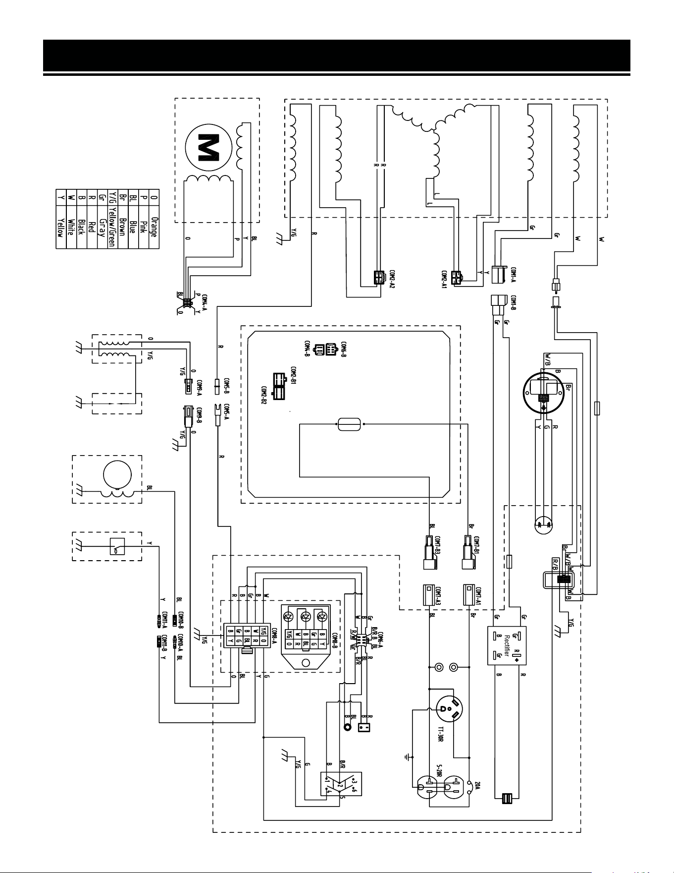
WIRING DIAGRAM
Direct Current Winding
Magnet
CO Power Winding
Ignition Coil
Stepper Motor
CO Sensor
CO Sensor LED
Eco-Mode
Switch
Reset
Engine
Switch
USB
Fuse
Controller
Fuse
Inverter
Ignitor
Control Panel Unit
Oil SensorTriggerSpark PlugIgnition Coil
Flywheel
33
EXPLODED VIEW & PARTS LIST
NOTE: Replacement parts can be purchased from wenproducts.com, or by calling our customer service at
1-847-429-9263, M-F 8-5 CST. Parts and accessories that wear down over the course of normal use are not
covered by the two-year warranty.
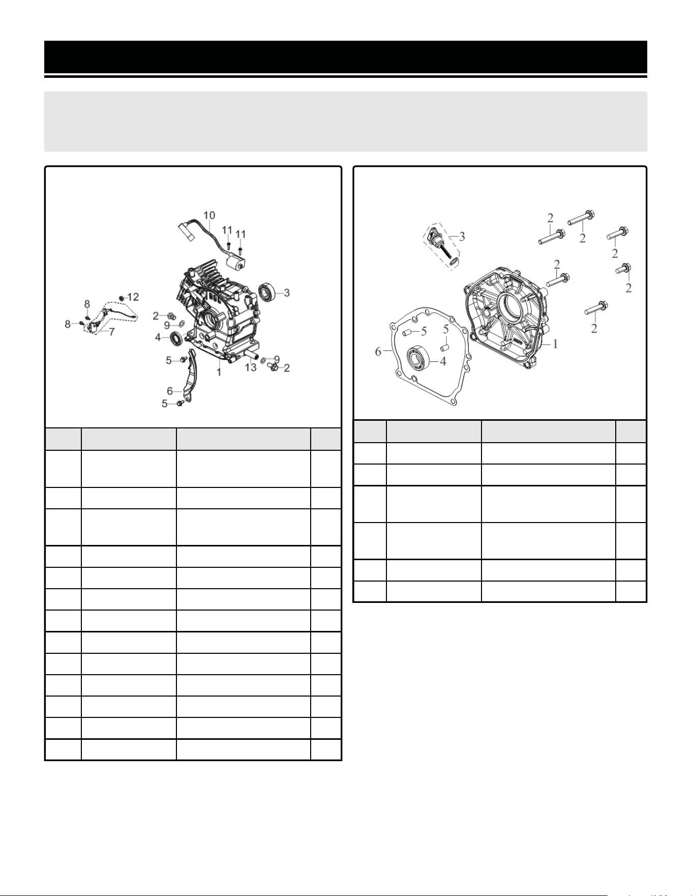
No. Part No. Description Qty.
1-1 GN400i-0101
Crankcase
Subassembly
1
1-2 GN400i-0102 Drain Plug Bolt 2
1-3 GN400i-0103
Deep Groove Ball
Bearing
1
1-4 56310i-0306 Oil Seal 1
1-5 56200-1202 Bolt 2
1-6 GN400i-0106 Lower Shield 1
1-7 56310i-0211 Engine Oil Sensor 1
1-8 56200-0502 Hex Head Bolt 2
1-9 56380i-0102 Flat Washer 2
1-10 GN400i-0110 Ignition Coil 1
1-11 GN400i-0111 Bolt 2
1-12 56310i-0210 Nut 1
1-13 GN400i-0113 Oil Drain Tube 1
ASSEMBLY 1 - CRANKCASE
No. Part No. Description Qty.
2-1 GN400i-0201 Crankcase Cover 1
2-2 56310i-0307 Bolt 6
2-3 GN400i-0203
Oil Dipstick
Subassembly
1
2-4 GN400i-0204
Deep Groove Ball
Bearing
1
2-5 GN400i-0205 Positioning Pin 2
2-6 GN400i-0206 Crankcase Gasket 1
ASSEMBLY 2 - CRANKCASE COVER
34
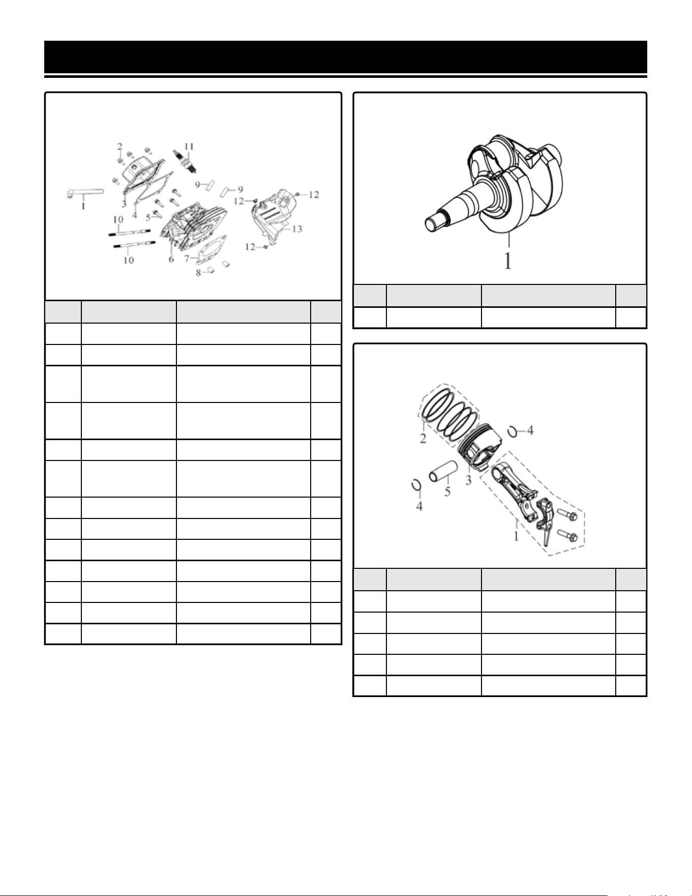
EXPLODED VIEW & PARTS LIST
No. Part No. Description Qty.
3-1 GN400i-0301 Breather Tube 1
3-2 56200-1202 Bolt 4
3-3 GN400i-0303
Cylinder Head Cover
Assembly
1
3-4 GN400i-0304
Cylinder Head Cover
Gasket
1
3-5 56310i-0106 Cylinder Head Bolt 4
3-6 GN400i-0306
Cylinder Head
Subassembly
1
3-7 GN400i-0307 Cylinder Head Gasket 1
3-8 56380i-0311 Positioning Pin 2
3-9 56310i-0109 Stud Bolt 2
3-10 56380i-0309 Stud Bolt 2
3-11 56310i-0104 Spark Plug 1
3-12 56200-0706 Bolt 3
3-13 GN400i-0313 Cylinder Body Shroud 1
ASSEMBLY 3 - CYLINDER HEAD
No. Part No. Description Qty.
4-1 GN400i-0401 Crankshaft Assembly 1
ASSEMBLY 4 - CRANKSHAFT
No. Part No. Description Qty.
5-1 GN400i-0501 Connecting Rod 1
5-2 56310i-0501 Piston Ring Assembly 1
5-3 GN400i-0503 Piston 1
5-4 56310i-0505 Piston Pin Clip 2
5-5 56310i-0504 Piston Pin 1
ASSEMBLY 5 - PISTON RING
35
ASSEMBLY 7 - RECOIL STARTER
No. Part No. Description Qty.
6-1 GN400i-0601 Camshaft Assembly 1
6-2 GN400i-0602 Valve Lock Nut 2
6-3 GN400i-0603 Adjusting Valve Nut 2
6-4 GN400i-0604 Valve Rocker 2
6-5 GN400i-0605 Rockshaft Bolt 2
6-6 GN400i-0606
Lifter Stopper Plate
Subassembly
1
6-7 GN400i-0607 Vavle Lifter 2
6-8 56310i-0607 Valve Tappet 2
6-9 GN400i-0609 Set Valves 1
6-10 56310i-0603 Seal Guide 1
6-11 56310i-0604 Valve Spring 2
6-12 56380i-0605 Valve Spring Seat 2
6-13 56310i-0606 Valve Lock Clamp 4
EXPLODED VIEW & PARTS LIST
ASSEMBLY 6 - VALVE & CAMSHAFT
No. Part No. Description Qty.
7-1 GN400i-0701
Manual Starting
Assembly
1
7-2 56200-1202 Bolt 4
7-3 GN400i-0703 Wire Clip 1
No. Part No. Description Qty.
8-1 GN400i-0801
Carburetor Insulator
Gasket
1
8-2 GN400i-0802
Carburetor Insualtor
Plate
1
8-3 GN400i-0803
Step Motor Heat-Proof
Plate
1
8-4 56380i-0803 Carburetor Seal Gasket 2
8-5 GN400i-0805 Carburetor Assembly 1
8-7 56200-1305 Fuel Strainer 1
ASSEMBLY 8 - CARBURETOR
3736
No. Part No. Description Qty.
10-1 GN400i-1001 Air Cleaner Seal Gasket 1
10-2 GN400i-1002 Air Cleaner Seal Gasket 1
10-3 56200-0506 Hex Flange Nut 2
10-4 56310i-1420 Bolt 1
No. Part No. Description Qty.
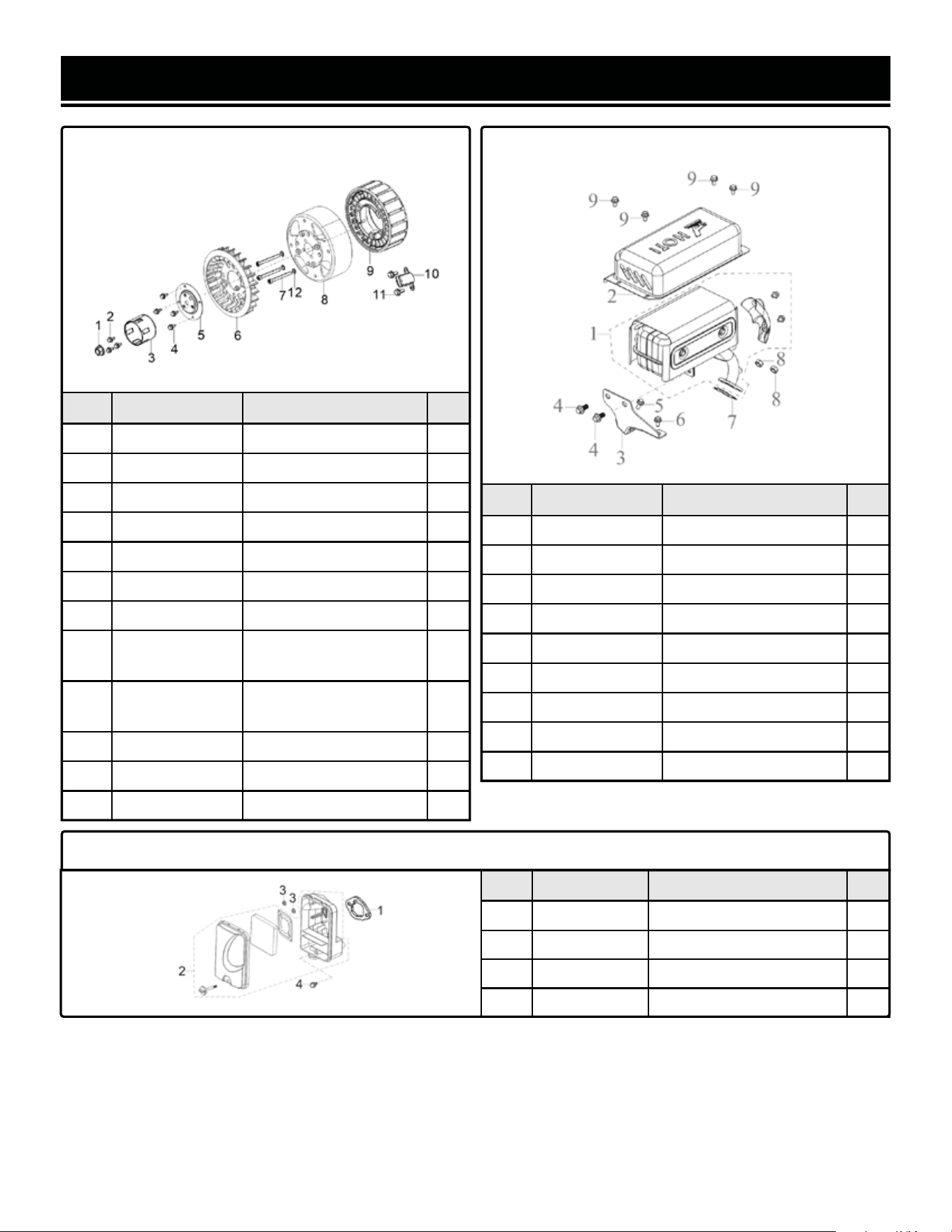
9-1 56310i-1101 Flywheel Nut 1
9-2 56200-0706 Bolt 3
9-3 GN400i-0903 Starter Pulley 1
9-4 56200-1202 Hex Bolt 4
9-5 56380i-0705 Starter Cup Seat 1
9-6 GN400i-0906 Impeller 1
9-7 56310i-1103 Hex Cap Screw 3
9-8 GN400i-0908
Magneto Roller Case
Subassembly
1
9-9 GN400iX-0909
Magneto Stator
Subassembly
1
9-10 GN400i-0910 Trigger Assembly 1
9-11 56310i-1106 Bolt 2
9-12 GN400IX-0912 Flat Washer 3
EXPLODED VIEW & PARTS LIST
ASSEMBLY 9 - FLYWHEEL
No. Part No. Description Qty.
11-1 GN400i-1101 Muffler Assembly 1
11-2 GN400i-1102 Muffler Outer Cover 1
11-3 GN400i-1103 Muffler Bracket 1
11-4 GN400i-1104 Hex Flange Bolt 2
11-5 56200-1202 Hex Flange Face Bolt 1
11-6 GN400i-1106 Hex Flange Bevel Bolt 1
11-7 GN400i-1107 Exhaust Outlet Gasket 1
11-8 GN400i-1108 Hex Nut 2
11-9 56380i-0313 Hex Flange Face Bolt 4
ASSEMBLY 11 - MUFFLER
ASSEMBLY 10 - AIR FILTER
3736
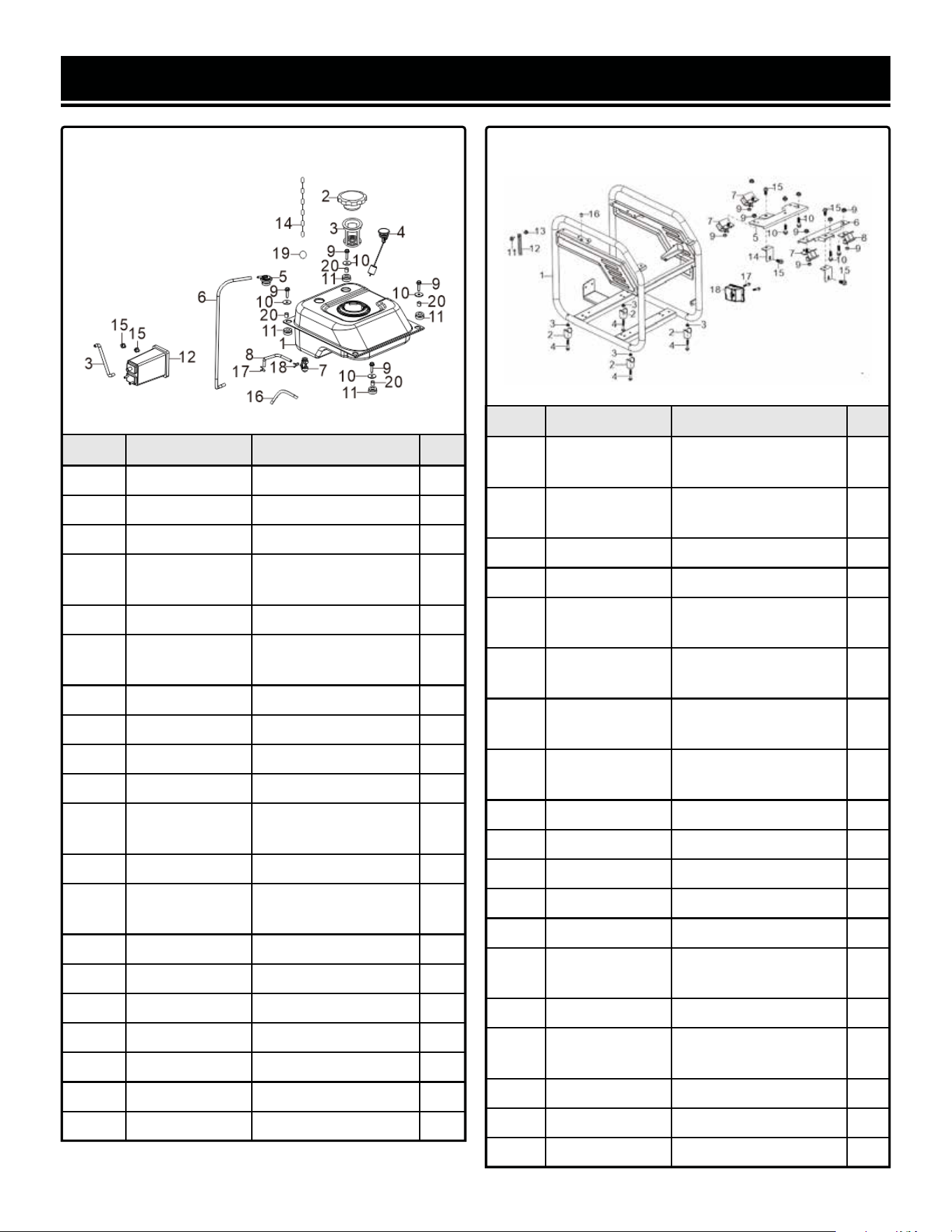
EXPLODED VIEW & PARTS LIST
No. Part No. Description Qty.
12-1 GN400i-1201 Fuel Tanke 1
12-2 GN400i-1202 Fuel Tank Cover 1
12-3 GN400i-1203 Fuel Strainer 1
12-4 GN400i-1204
Oil Leveler
Assembly
1
12-5 GN400i-1205 One-way Valve 1
12-6 GN400i-1206B
Fuel Steam Rubber
Hose
1
12-7 GN400i-1207 Fuel Cock Assembly 1
12-8 GN400i-1208 Fuel Tube 1
12-9 GN400i-1209 Bolt 4
12-10 GN400i-1210 Flat Washer 4
12-11 56380i-1207
Fuel Tank Rubber
Sleeve
4
12-12 GN400i-1212 Fuel Steam Collector 1
12-13 GN400i-1213
Air Cleaner Rubber
Hose
1
12-14 GN400i-1214 Fuel Cap Chain 1
12-15 GN400i-1215 Bolt 2
12-16 GN400i-1216 Rubber Jacket 1
12-17 GN400i-1217 Pipe Clamp 1
12-18 GN400i-1218 Collar 1
12-19 GN400iX-1219 Fuel Cap Chain Clip 1
12-20 GN400I-1220 Bushing 4
ASSEMBLY 12 - FUEL TANK
No. Part No. Description Qty.
13-1 GN400iX-1301
Engine Frame
Assembly
1
13-2 GN400i-1302
Engine Frame Shock
Absorber Seat
4
13-3 GN400i-1303 Hex Flange Nut 4
13-4 GN400i-1304 Hex Flange Bolt 4
13-5 GN400i-1305
Engine Fixed Bottom
Plate, Back
1
13-6 GN400i-1306
Engine Fixed Bottom
Plate, Front
1
13-7 56310i-1409
Enginer Frame Left
Cushion
3
13-8 56310i-1411
Enginer Frame Right
Cushion
1
13-9 56310i-1404 Hex Flange Nut 11
13-10 GN400i-1310 Hex Flange Bolt 4
13-11 GN400i-1311 Bolt 1
13-12 GN400i-1312 Wire Clip 1
13-13 GN400i-1313 Nut 1
13-14 GN400i-1314
Transportation
Support Block
2
13-15 GN400i-1315 Hex Flange Bolt 4
13-16 GN400i-1316
Protective Rubber
Sleeve
1
13-17 GN400iX-1317 Pan Head Screw 2
13-18 GN625iX-1430 CO Sensor Module 1
13-19 GN400iX-1319 Thermal Baffle 1
ASSEMBLY 13 - FRAME
3938
EXPLODED VIEW & PARTS LIST
No. Part No. Description Qty.
14-1 GN400iX-1401 Control Panel Assembly 1
14-2 GN400i-1402 Panel Seat 1
14-3 GN400i-1403 Bolt 4
14-4 GN400i-1404 Screw 4
14-5 GN625iX-1430 CO Sensor Module 1
14-6 GN400i-1406 Ignitor 1
14-7 GN400i-1407 Choke 1
14-8 GN400i-1408 Rectification Bridge 1
14-9 56380i-1423
Power Supply Socket
Subassembly
1
14-10 56380i-1424
Power Supply Socket
Subassembly
1
14-11 GN400i-1411 Resetting Button 1
14-12 56380i-1421
Power Supply Socket
Subassembly
1
14-13 GN400i-1413
Grouding Terminal
Subassembly
1
14-14 GN400i-1414 DC Socket Subassembly 1
14-15 GN400i-1415 Overcurrent Protector 1
14-16 56380i-1422 Switch Subassembly 1
14-17 GN400i-1417 Switch Subassembly 1
14-18 GN400i-1418B
Power Supply Socket
Subassembly
1
14-19 GN400i-1419 Inverter 1
14-20 GN400i-1420 Bolt 3
ASSEMBLY 14 - CONTROL PANEL

3938
WARRANTY STATEMENT
WEN Products is committed to building tools that are dependable for years. Our warranties are consistent with this
commitment and our dedication to quality.
LIMITED WARRANTY OF WEN PRODUCTS FOR HOME USE
GREAT LAKES TECHNOLOGIES, LLC (“Seller”) warrants to the original purchaser only, that all WEN consumer power
tools will be free from defects in material or workmanship during personal use for a period of two (2) years from date
of purchase or 500 hours of use; whichever comes first. Ninety days for all WEN products if the tool is used for pro-
fessional or commercial use. Purchaser has 30 days from the date of purchase to report missing or damaged parts.
SELLER’S SOLE OBLIGATION AND YOUR EXCLUSIVE REMEDY under this Limited Warranty and, to the extent per-
mitted by law, any warranty or condition implied by law, shall be the replacement of parts, without charge, which are
defective in material or workmanship and which have not been subjected to misuse, alteration, careless handling,
misrepair, abuse, neglect, normal wear and tear, improper maintenance, improper storage, incorrect lubricants/fuels,
or other conditions adversely affecting the Product or the component of the Product, whether by accident or inten-
tionally, by persons other than Seller. To make a claim under this Limited Warranty, you must make sure to keep a
copy of your proof of purchase that clearly defines the Date of Purchase (month and year) and the Place of Purchase.
Place of Purchase must be a direct vendor of Great Lakes Technologies, LLC. Purchasing through third party vendors,
including but not limited to garage sales, pawn shops, resale shops, or any other secondhand merchant, voids the
warranty included with this product. Contact [email protected] or 1-847-429-9263 with the following
information to make arrangements: your shipping address, phone number, serial number, required part numbers,
and proof of purchase. Damaged or defective parts and products may need to be sent to WEN before the replace-
ments can be shipped out.
Upon the confirmation of a WEN representative, your product may qualify for repairs and service work. When re-
turning a product for warranty service, the shipping charges must be prepaid by the purchaser. The product must
be shipped in its original container (or an equivalent), properly packed to withstand the hazards of shipment. The
product must be fully insured with a copy of the proof of purchase enclosed. There must also be a description of the
problem in order to help our repairs department diagnose and fix the issue. Repairs will be made and the product
will be returned and shipped back to the purchaser at no charge for addresses within the contiguous United States.
THIS LIMITED WARRANTY DOES NOT APPLY TO ITEMS THAT WEAR OUT FROM REGULAR USAGE OVER TIME,
INCLUDING FILTERS, SPARK PLUGS, VOLTAGE REGULATORS, BRUSHES, GASKETS, O-RINGS, WHEEL KITS, BAT-
TERIES, RECOIL STARTERS, HIGH PRESSURE HOSES, SPRAY GUNS, ETC. ANY IMPLIED WARRANTIES SHALL BE
LIMITED IN DURATION TO TWO (2) YEARS FROM DATE OF PURCHASE. SOME STATES IN THE U.S. AND SOME
CANADIAN PROVINCES DO NOT ALLOW LIMITATIONS ON HOW LONG AN IMPLIED WARRANTY LASTS, SO THE
ABOVE LIMITATION MAY NOT APPLY TO YOU.
IN NO EVENT SHALL SELLER BE LIABLE FOR ANY INCIDENTAL OR CONSEQUENTIAL DAMAGES (INCLUDING BUT
NOT LIMITED TO LIABILITY FOR LOSS OF PROFITS) ARISING FROM THE SALE OR USE OF THIS PRODUCT. SOME
STATES IN THE U.S. AND SOME CANADIAN PROVINCES DO NOT ALLOW THE EXCLUSION OR LIMITATION OF IN-
CIDENTAL OR CONSEQUENTIAL DAMAGES, SO THE ABOVE LIMITATION OR EXCLUSION MAY NOT APPLY TO YOU.
THIS LIMITED WARRANTY GIVES YOU SPECIFIC LEGAL RIGHTS, AND YOU MAY ALSO HAVE OTHER RIGHTS
WHICH VARY FROM STATE TO STATE IN THE U.S., PROVINCE TO PROVINCE IN CANADA AND FROM COUNTRY TO
COUNTRY.
THIS LIMITED WARRANTY APPLIES ONLY TO ITEMS SOLD WITHIN THE UNITED STATES OF AMERICA, CANADA
AND THE COMMONWEALTH OF PUERTO RICO. FOR WARRANTY COVERAGE WITHIN OTHER COUNTRIES, CON-
TACT THE WEN CUSTOMER SUPPORT LINE. FOR WARRANTY PARTS OR PRODUCTS REPAIRED UNDER WARRAN-
TY SHIPPING TO ADDRESSES OUTSIDE OF THE CONTIGUOUS UNITED STATES, ADDITIONAL SHIPPING CHARGES
MAY APPLY.

V. 2022.11.14
THANKS FOR
REMEMBERING