Air Conditioner Disconnect
Instruction Manual
Warning
• Electric shock hazard. Voltage or current hazard. Failure to follow these instructions could result in serious bodily injury
or death.
• Most electric product related incidents are caused by failure to observe basic safety rules or precaution. Users and
Installer must be alert to potential hazards.
•
of NFPA70: National Electrical Code® and all state and local codes.
• Ensure electricity from the circuit protective device is compatible with the rating of the air conditioner disconnect.
• Always test the feeder cable with a voltage tester and ensure power is disconnected before working on the disconnect
device.
Warning and Safety
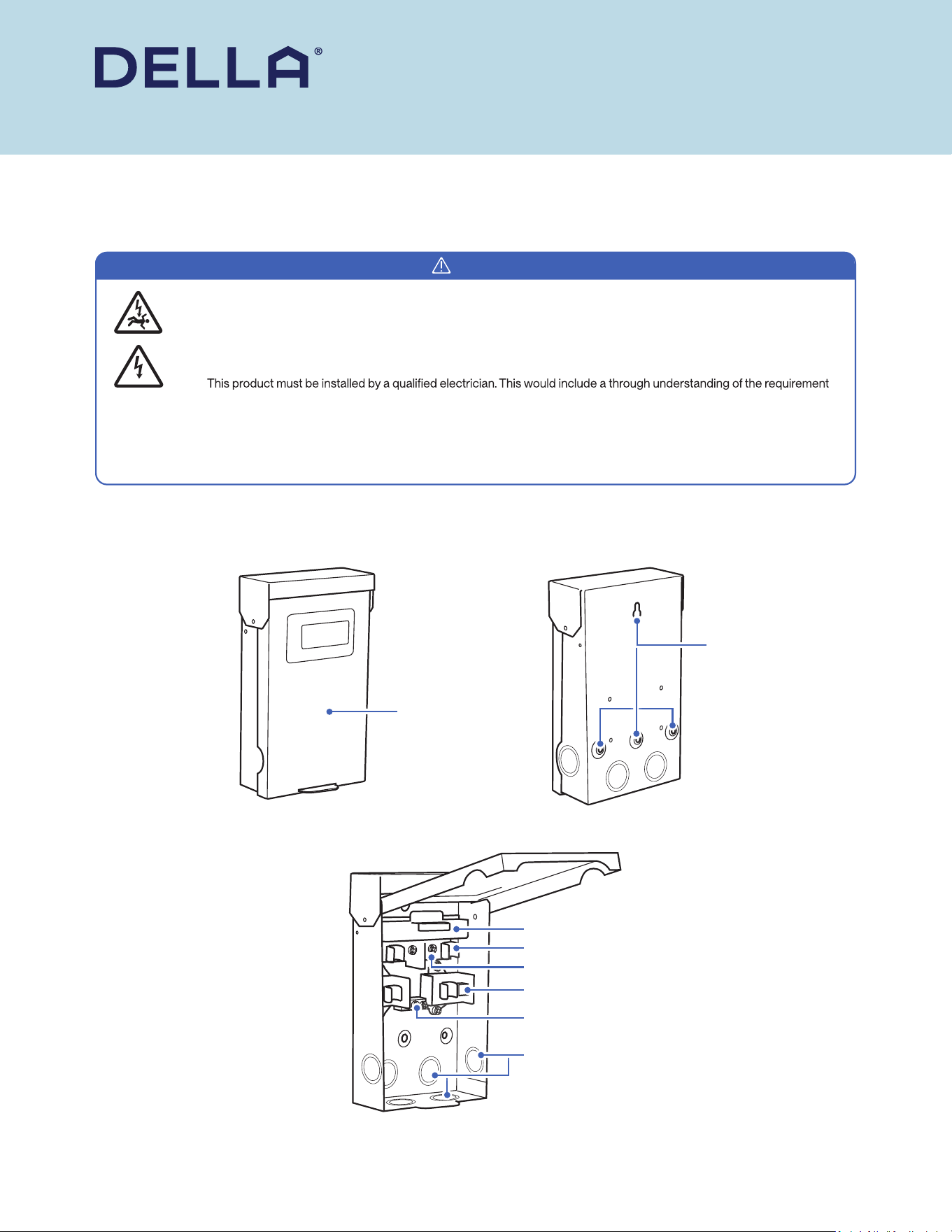
Product Overview
• Read this guide before installation. Failure to follow the safety instructions may result in property damage or serious injury.
• Please Keep this manual.
v.20250321048-30AMP-F / 048-60AMP-F
Front Cover
Fuse Clip
Pullout Mechanism
Load Lug
Line Lug
Ground Lug
Mounting Holes
Knockout
Tools Needed (Not included)
Installation
• Cable Stripper
• Fish Tape
• Hacksaw / Pipe Cutter
• Hammer
• Spirit Level
• Voltage Tester
• Pliers
• Continuity Tester
• Screwdriver
• Measuring Tape
• Torque Wrench
• Utility Knife
• Drill and Bits
• Electrical Cable (of correct size, type, and length)
• Mounting Screws
• Electrical connectors / couplings
1. Open the front cover and slide it into the retaining slot to keep it open.
2. Pull the handle on the pullout mechanism and remove the deadfront barrier. Keep these parts as they have valuable information and must be
re-installed later in order to complete the installation.
3. Use a screwdriver and hammer to remove knockouts according to your installation. The knockouts can accomodate 1/2”, 3/4” and 1” conduit
connector. Make sure to use a conduit connector on the knockout and protect the electrical cable from any sharp edges.
4. Pass the electrical cable through the conduit connector into the disconnect box.
5. Mount the disconnect box to a wall by screwing screws through the pre-drilled holes on the back of the box.
6. Install class H or class K fuse (not included) between the line lug and load lug. Make sure the fuse sit securely on the fuse clip.
7. Connect the feeder cable from the circuit box to the line lug and the power cable from the air conditioner to the load lug.
Make sure to connect the ground wires to the groung lugs. Follow the torque values for the wire installation.
NOTE: Failing to use the correct cable or secure in required torque may cause the equipment to overheat.
8. Ensure every components are secured in place, and then re-install the pullout mechanism into the disconnect box to complete the circuit.
(ON marking on the pullout mechanism needs to be in the top position)
Installation Instruction
© Della All rights reserved.
The design and specications are subject to change without prior
notice for product improvement. Any updates to the manual will be
uploaded to the della website.
www.dellahome.com
support@dellahome.com
800–863–4143
6:00 a.m. – 4:00 p.m. PST Monday – Friday
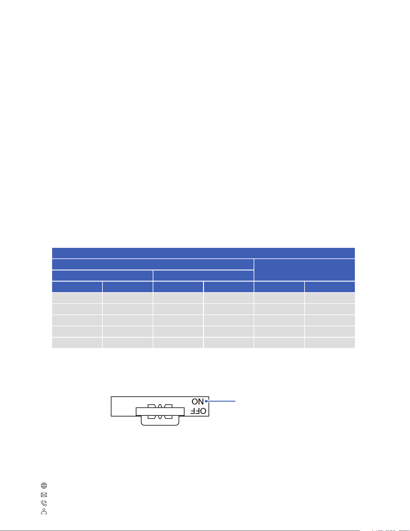
Lug Specication (60/75°C AL-CU Wire)
Wire Size (AWG)
Connector Torque (lb-ft)
Line / Load Equipment Load
CU AL CU AL Line / Load Equipment Load
14 / 14 / 35 20
10 - 12 10 - 12 10 - 12 10 - 12 35 20
8 8 8 8 40 25
6 - 4 6 - 4 6 - 4 6 - 4 45 25
3 3 / / 50 /
“ON” marking on top means the circuit is live
