

AS22225
Questions, problems, missing parts? Before returning to your retailer, call our customer
service department at 888-3KOBALT (888-356-2258), 8 a.m. – 8 p.m., EST,
Monday – Sunday. You could also contact us at [email protected].
ATTACH YOUR RECEIPT HERE
Serial Number Purchase Date
ITEM #5192324/5129684/5192325
BRUSHLESS
POWER HEAD
MODEL #KMH 1024-03
Español p. 15
KOBALT and logo design are trademarks or
registered trademarks of LF, LLC. All rights reserved.

2
TABLE OF CONTENTS
Product Specications ......................................................................................2
Packaging Contents ......................................................................................... 3
Safety Information ............................................................................................ 4
Preparation .......................................................................................................8
Assembly Instructions ......................................................................................9
Operating Instructions .................................................................................... 12
Care and Maintenance ...................................................................................14
Troubleshooting.............................................................................................. 14
Warranty ......................................................................................................... 14
PRODUCT SPECIFICATIONS
COMPONENT SPECIFICATIONS
Rated voltage 24V d.c.
Recommended operating temperature 32°F (0°C) - 104°F (40°C)
Recommended storage temperature 32°F (0°C) - 104°F (40°C)
3
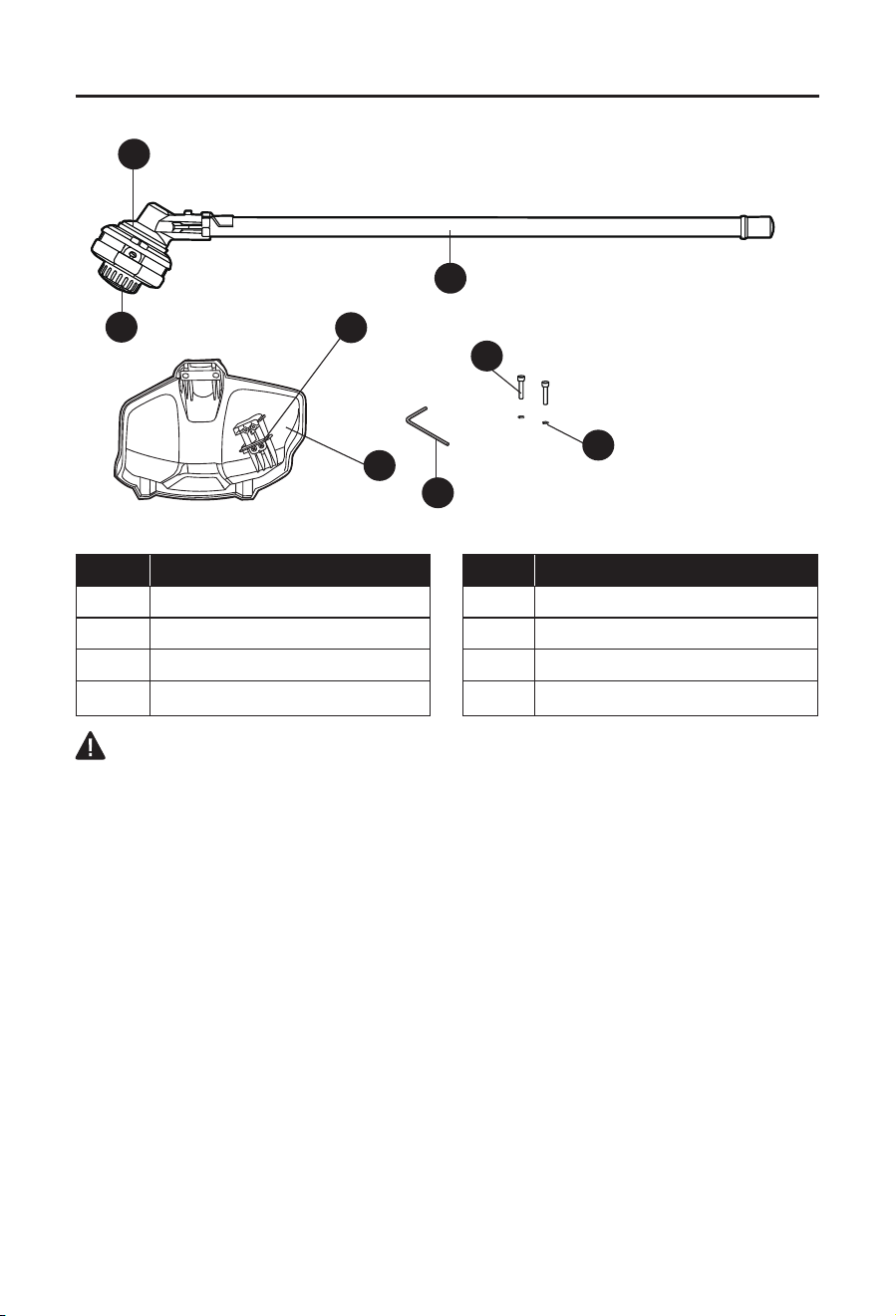
PACKAGE CONTENTS
C
E F
H
J
B D G
I
A
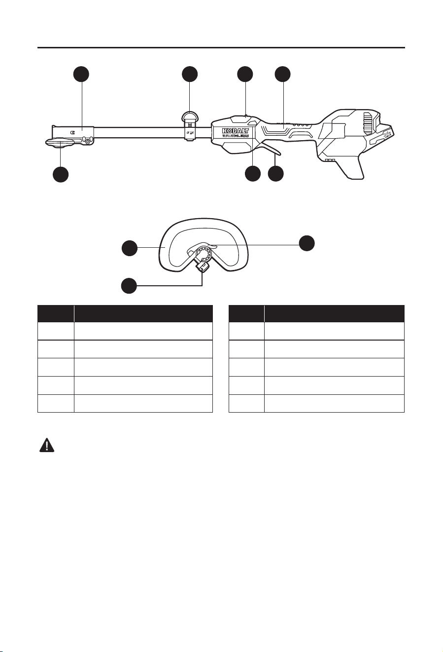
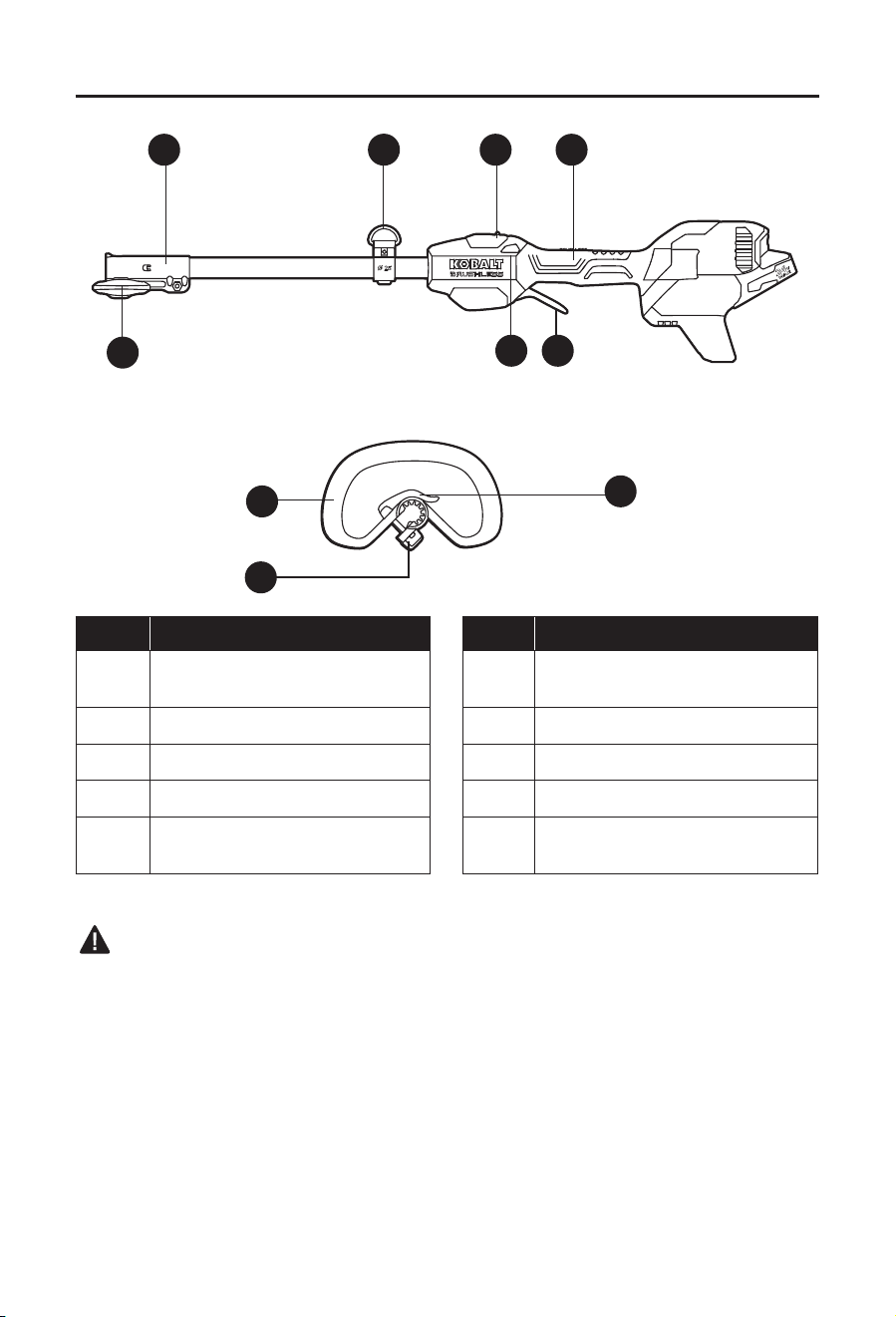
PART DESCRIPTION PART DESCRIPTION
A Wing knob F Variable-speed trigger switch
B Coupler G Rear handle
C Shoulder-strap loop H Front-assist handle
D Speed mode switch I Screw knob
E Lock-off button J Assist-handle lock-lever
WARNING:
• Remove the tool from the package and examine it carefully. Do not discard the carton or any
packaging material until all parts have been examined.
• If any part of the tool is missing or damaged, do not attach the battery to use the tool until
the part has been repaired or replaced. Failure to heed this warning could result in serious
injury.

4
SAFETY INFORMATION
Please read and understand this entire manual before attempting to assemble or operate
this product. If you have any questions regarding the product, please call customer service
at 888-3KOBALT, 8 a.m. - 8 p.m., EST, Monday - Sunday. You could also contact us at
WARNING:
• The operation of any power tool can result in foreign objects being thrown into your eyes,
which can result in severe eye damage. Before beginning power-tool operation, always wear
safety goggles or safety glasses with side shields and a full-face shield, when needed. We
recommend using a wide vision safety mask over eyeglasses or standard safety glasses
with shields. Always use eye protection marked to comply with ANSI Z87.1.
• Some dust created by power sanding, sawing, grinding, drilling, and other construction
activities contains chemicals known to the state of California to cause cancer, birth defects,
or other reproductive harm. Some examples of these chemicals are:
– Lead from lead-based paints
– Crystalline silica from bricks, cement, and other masonry products
– Arsenic and chromium from chemically-treated lumber
• Your risk from these exposures varies, depending upon how often you do this type of work.
To reduce your exposure to these chemicals:
– Work in a well-ventilated area.
– Work with approved safety equipment, such as dust masks that are specially designed to
lter out microscopic particles.
– Avoid prolonged contact with dust from power sanding, sawing, grinding, drilling, and
other construction activities. Wear protective clothing and wash exposed areas with soap
and water. Allowing dust to get into your mouth or eyes or to lie on the skin may promote
absorption of harmful chemicals.
Know the Tool
To operate this tool, carefully read this manual and all labels afxed to the tool before using it.
Keep this manual available for future reference.
Important
This tool should be serviced only by a qualied service technician.
Read All Instructions Thoroughly

5
SAFETY INFORMATION
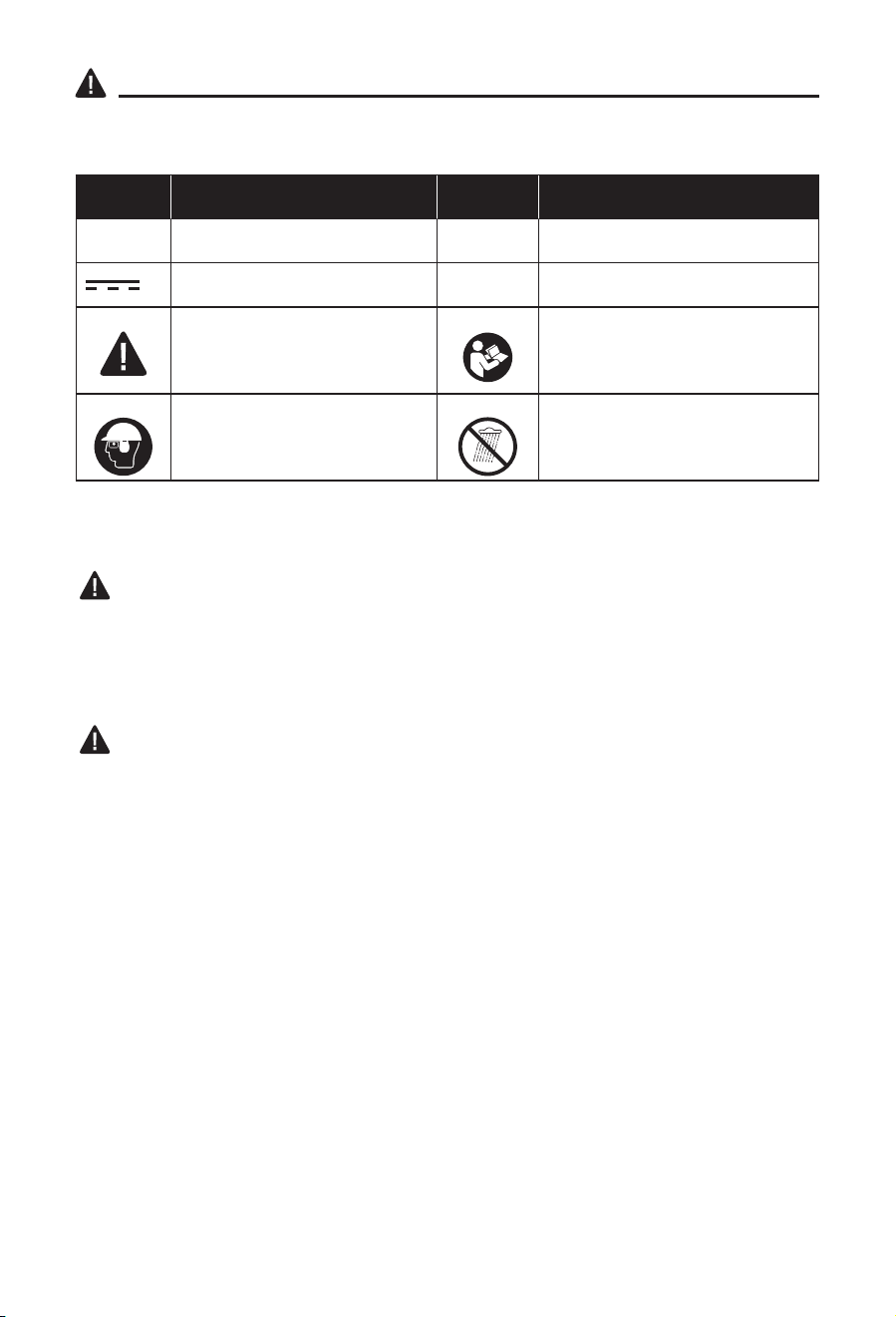
Some of the following symbols may be used on this tool. Please study them and their meaning.
Proper interpretation of these symbols will allow you to operate the tool better and more safely.
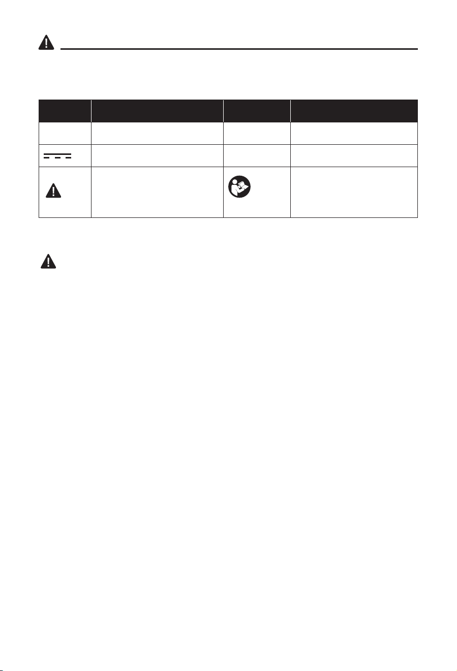
SYMBOL DEFINITION SYMBOL DEFINITION
V Volts n
0
No-load speed
Direct current /min or RPM Revolutions per Minute
A danger, warning, or caution.
It means ‘Attention! Your
safety is involved.’
To reduce the risk of injury,
user must read instruction
manual.
General Power Tool Safety Warnings
WARNING
• Read all safety warnings, instructions, illustrations and specications provided with
this power tool. Failure to follow all instructions listed below may result in electric shock,
re and/or serious injury.
Save all warnings and instructions for future reference
• The term “power tool” in the warnings refers to your mains-operated (corded) power tool or
battery-operated (cordless) power tool.
Work Area Safety
• Keep work area clean and well lit. Cluttered or dark areas invite accidents.
• Do not operate power tools in explosive atmospheres, such as in the presence of
ammable liquids, gases or dust. Power tools create sparks, which may ignite the dust or
fumes.
• Keep children and bystanders away while operating a power tool. Distractions can
cause you to lose control.
Electrical Safety
• Power tool plugs must match the outlet. Never modify the plug in any way. Do not use
any adapter plugs with earthed (grounded) power tools. Unmodied plugs and matching
outlets will reduce risk of electric shock.
• Avoid body contact with earthed or grounded surfaces, such as pipes, radiators,
ranges and refrigerators. There is an increased risk of electric shock if your body is
earthed or grounded.
• Do not expose power tools to rain or wet conditions. Water entering a power tool will
increase the risk of electric shock.
• Do not abuse the cord. Never use the cord for carrying, pulling or unplugging the
power tool. Keep cord away from heat, oil, sharp edges or moving parts. Damaged or
entangled cords increase the risk of electric shock.
• When operating a power tool outdoors, use an extension cord suitable for outdoor
use. Use of a cord suitable for outdoor use reduces the risk of electric shock.
• If operating a power tool in a damp location is unavoidable, use a ground fault circuit
interrupter (GFCI) protected supply. Use of a GFCI reduces the risk of electric shock.

6
SAFETY INFORMATION
Personal Safety
• Stay alert, watch what you are doing and use common sense when operating a power
tool. Do not use a power tool while you are tired or under the inuence of drugs,
alcohol or medication. A moment of inattention while operating power tools may result in
serious personal injury.
• Use personal protective equipment. Always wear eye protection. Protective equipment
such as a dust mask, non-skid safety shoes, hard hat or hearing protection used for
appropriate conditions will reduce personal injuries.
• Prevent unintentional starting. Ensure the switch is in the off-position before
connecting to power source and/or battery pack, picking up or carrying the tool.
Carrying power tools with your nger on the switch or energising power tools that have the
switch on invites accidents.
• Remove any adjusting key or wrench before turning the power tool on. A wrench or a
key left attached to a rotating part of the power tool may result in personal injury.
• Do not overreach. Keep proper footing and balance at all times. This enables better
control of the power tool in unexpected situations.
• Dress properly. Do not wear loose clothing or jewelry. Keep your hair and clothing
away from moving parts. Loose clothes, jewelry or long hair can be caught in moving
parts.
• If devices are provided for the connection of dust extraction and collection facilities,
ensure these are connected and properly used. Use of dust collection can reduce dust-
related hazards.
• Do not let familiarity gained from frequent use of tools allow you to become
complacent and ignore tool safety principles. A careless action can cause severe injury
within a fraction of a second.
Power tool use and care
• Do not force the power tool. Use the correct power tool for your application. The
correct power tool will do the job better and safer at the rate for which it was designed.
• Do not use the power tool if the switch does not turn it on and off. Any power tool that
cannot be controlled with the switch is dangerous and must be repaired.
• Disconnect the plug from the power source and/or remove the battery pack,
if detachable, from the power tool before making any adjustments, changing
accessories, or storing power tools. Such preventive safety measures reduce the risk of
starting the power tool accidentally.
• Store idle power tools out of the reach of children and do not allow persons
unfamiliar with the power tool or these instructions to operate the power tool. Power
tools are dangerous in the hands of untrained users.
• Maintain power tools and accessories. Check for misalignment or binding of moving
parts, breakage of parts and any other condition that may affect the power tool’s
operation. If damaged, have the power tool repaired before use. Many accidents are
caused by poorly maintained power tools.
• Keep cutting tools sharp and clean. Properly maintained cutting tools with sharp cutting
edges are less likely to bind and are easier to control.
• Use the power tool, accessories and tool bits etc. in accordance with these
instructions, taking into account the working conditions and the work to be
performed. Use of the power tool for operations different from those intended could result in
a hazardous situation.

7
SAFETY INFORMATION
• Keep handles and grasping surfaces dry, clean and free from oil and grease. Slippery
handles and grasping surfaces do not allow for safe handling and control of the tool in
unexpected situations.
Battery Tool Use and Care
• Recharge only with the charger specied by the manufacturer. A charger that is suitable
for one type of battery pack may create a risk of re when used with another battery pack.
• Use power tools only with specically designated battery packs. Use of any other
battery packs may create a risk of injury and re.
• When battery pack is not in use, keep it away from other metal objects, like paper
clips, coins, keys, nails, screws or other small metal objects, that can make a
connection from one terminal to another. Shorting the battery terminals together may
cause burns or a re.
• Under abusive conditions, liquid may be ejected from the battery; avoid contact. If
contact accidentally occurs, ush with water. If liquid contacts eyes, additionally seek
medical help. Liquid ejected from the battery may cause irritation or burns.
• Do not use a battery pack or tool that is damaged or modied. Damaged or modied
batteries may exhibit unpredictable behavior resulting in re, explosion or risk of injury.
• Do not expose a battery pack or tool to re or excessive temperature. Exposure to re
or temperature above 265°F (130°C) may cause explosion.
• Follow all charging instructions and do not charge the battery pack or tool outside the
temperature range specied in the instructions. Charging improperly or at temperatures
outside the specied range may damage the battery and increase the risk of re.
Service
• Have your power tool serviced by a qualied repair person using only identical
replacement parts. This will ensure that the safety of the power tool is maintained.
• Never service damaged battery packs. Service of battery packs should only be performed
by the manufacturer or authorized service providers.
Additional Warnings
• Use only with the battery packs and chargers listed below:
BATTERY PACK CHARGER
KB 224-03; KB 424-03; KB 524-03;
KB 624-03; KXB 424-03; KXB 824-03
KRC 2445-03; KCH 2401-03; KCH 2411-03;
KRC 2490-03; KRC 2024-03; KDPC 124-03
• This power head may be used with the following attachments only:
ATTACHMENT TYPE MODEL NUMBER
String Trimmer KMS 1040-03
Edger KEG 1040-03
Brush cutter KMB 1040-03
Detacher KMD 1040-03
Pole Saw KMPS 1040-03
Pole Hedge Trimmer KMPH 1040-03

8
SAFETY INFORMATION
See operator’s manual for your KOBALT KMS 1040-03 String Trimmer for its use with
this power head.
See operator’s manual for your KOBALT KEG 1040-03 Edger for its use with this power
head.
See operator’s manual for your KOBALT KMB 1040-03 Brush cutter for its use with this
power head.
See operator’s manual for your KOBALT KMD 1040-03 Detacher for its use with this
power head.
See operator’s manual for your KOBALT KMPS 1040-03 Pole Saw for its use with this
power head.
See operator’s manual for your KOBALT KMPH 1040-03 Pole Hedge Trimmer for its use
with this power head.
SAVE THESE INSTRUCTIONS
PREPARATION
Know Your Power Head
Before attempting to use the power head, familiarize yourself with all of its operating features
and safety requirements.
WARNING:
• Do not allow familiarity with the tool to cause carelessness. Remember that one careless
moment is enough to cause severe injury. Before attempting to use any tool, be sure to
become familiar with all of the operating features and safety instructions.
• Do not attempt to modify this tool or create accessories not recommended for use with this
tool. Any such alteration or modication is misuse and could result in a hazardous condition
leading to possible serious personal injury.
9
ASSEMBLY INSTRUCTIONS
WARNING
• Read and understand entire Operator’s Manual for each optional attachment used with this
power head and follow all warnings and instructions. Failure to follow all instructions could
result in electric shock, re and/or serious personal injury.
• This 24V power head is designed to be used only with the attachment models that are
specied in this Operator’s Manual. Use of other,
unauthorized attachments could cause serious
personal injuries or property damage.
• Some accessories have specic requirements
related to safety. Always pay special attention to
such instructions in the manual that accompanies
each accessory.
• Never install, remove, or adjust any attachment
while the power head is running or with the
battery installed. Failure to stop the motor and
remove the battery can cause serious personal
injury. NEVER OPERATE THE POWER HEAD
WITHOUT AN ATTACHMENT.
WARNING
• Always remove the battery pack from the
product when you are assembling parts, making
adjustments, cleaning, or when the product is not
in use.
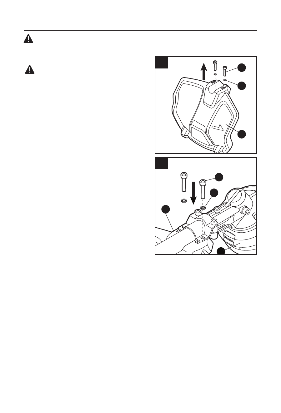
1. Installing and Removing the Power Head
Attachment
Installing the attachment
a. Remove the battery pack.
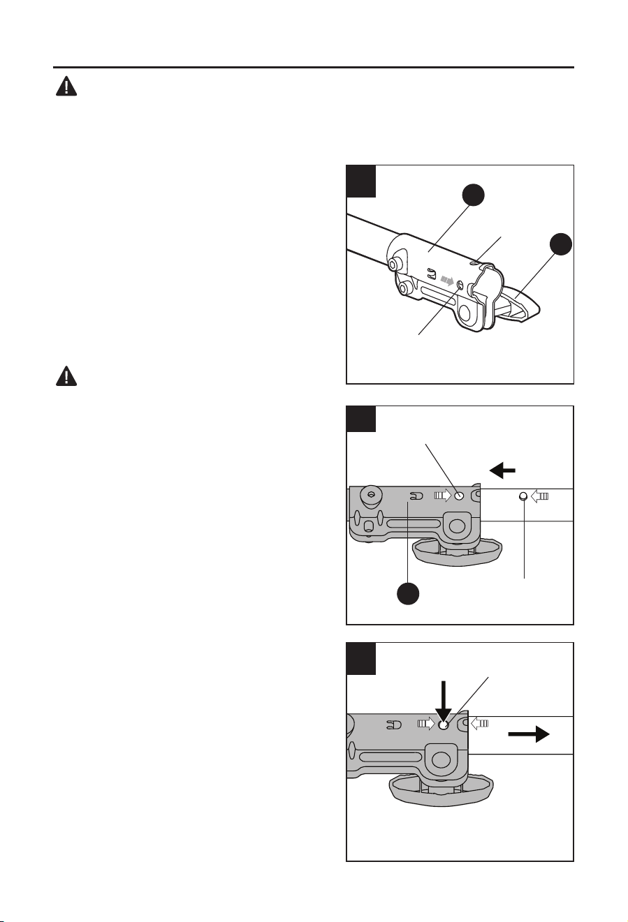
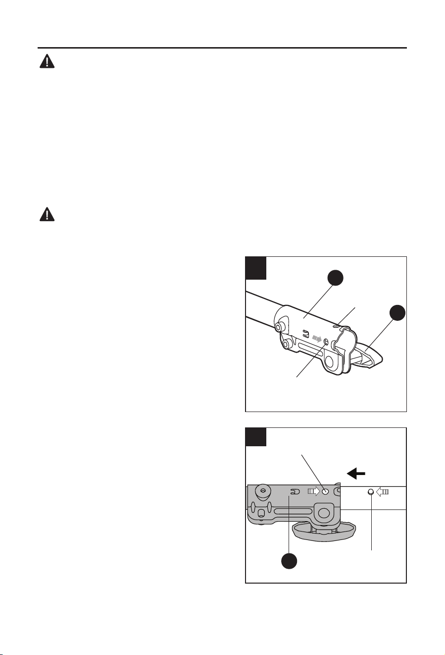
b. Loosen the wing knob (A) (Fig. 1a).
c. The power head has two grooves on the
coupler (B), ONLY the groove 1 is used to
connect attachments: KMS 1040-03,
KEG 1040-03, KMB 1040-03, KMD 1040-03,
KMPS 1040-03 and KMPH 1040-03.
d. Align the spring-loaded pin on the attachment
with the groove on the coupler (B) and push the
attachment shaft into the power head shaft until
the pin pops out of the groove and you hear an
audible “click” sound at the same time (Fig. 1b).
e. Pull the shaft of the attachment to verify that it
is securely locked into the coupler (B).
f. Tighten the wing knob (A) securely.
Removing the attachment
a. Remove the battery pack.
b. Loosen the wing knob (A).
c. Press down the spring-loaded pin and pull the
attachment shaft out of the coupler (Fig. 1c).
1a
B
A
Groove 1
Groove 2
B
1b
Groove
Pin
1c
Pin
10
ASSEMBLY INSTRUCTIONS
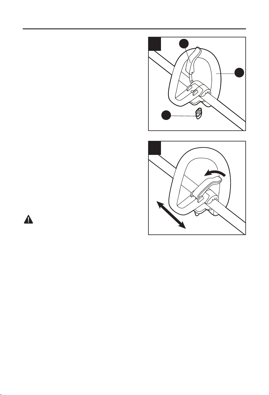
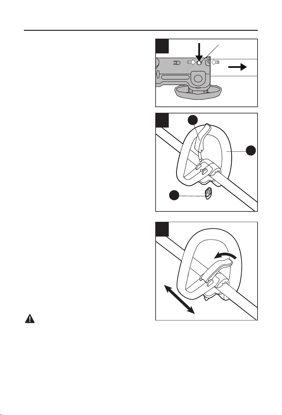
2. Mounting and Adjusting the Front-Assist
Handle
a. Remove the battery pack from the power head.
b. Remove the screw knob (I) and the lock lever
(J) from the front-assist handle (H).
c. Mount the front-assist handle on the shaft as
shown in Fig. 2a.
d. Insert the adjusting lever into the front-assist
handle, and then tighten the screw knob. Make
sure that the front-assist handle faces upwards
so that it points toward the rear handle
(Fig. 2b).
e. Lower the adjusting lever to secure the front-
assist handle onto the shaft so that it cannot
move on the shaft during operating.
To Adjust the Front-Assist Handle Position
The handle should be adjusted so that the arm
holding the front-assist handle is straight when
using the power head.
To adjust the front-assist handle (C) position, lift the
adjusting lever so that the front-assistant handle
can be moved to the desired position along the
shaft. Lower the adjusting lever so that the handle
cannot move on the shaft during operating.
WARNING:
• There is a tag on the power head shaft to limit
the adjustment distance of the front-assist handle
to meet the requirements of the front and rear
handle distance. Never adjust the front-assist handle beyond the tag position.
• Never operate the tool without the front-assist handle rmly in place.
2a
J
H
I
2b

11
ASSEMBLY INSTRUCTIONS
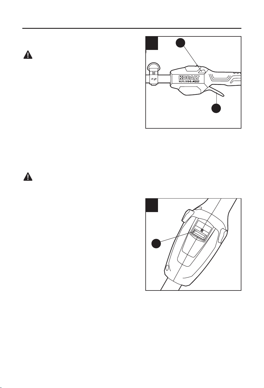
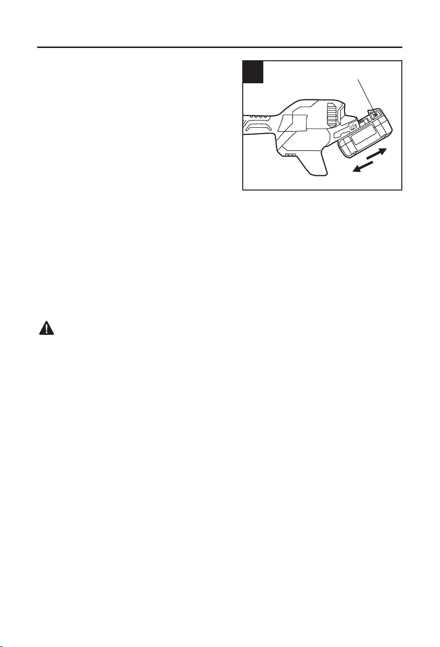
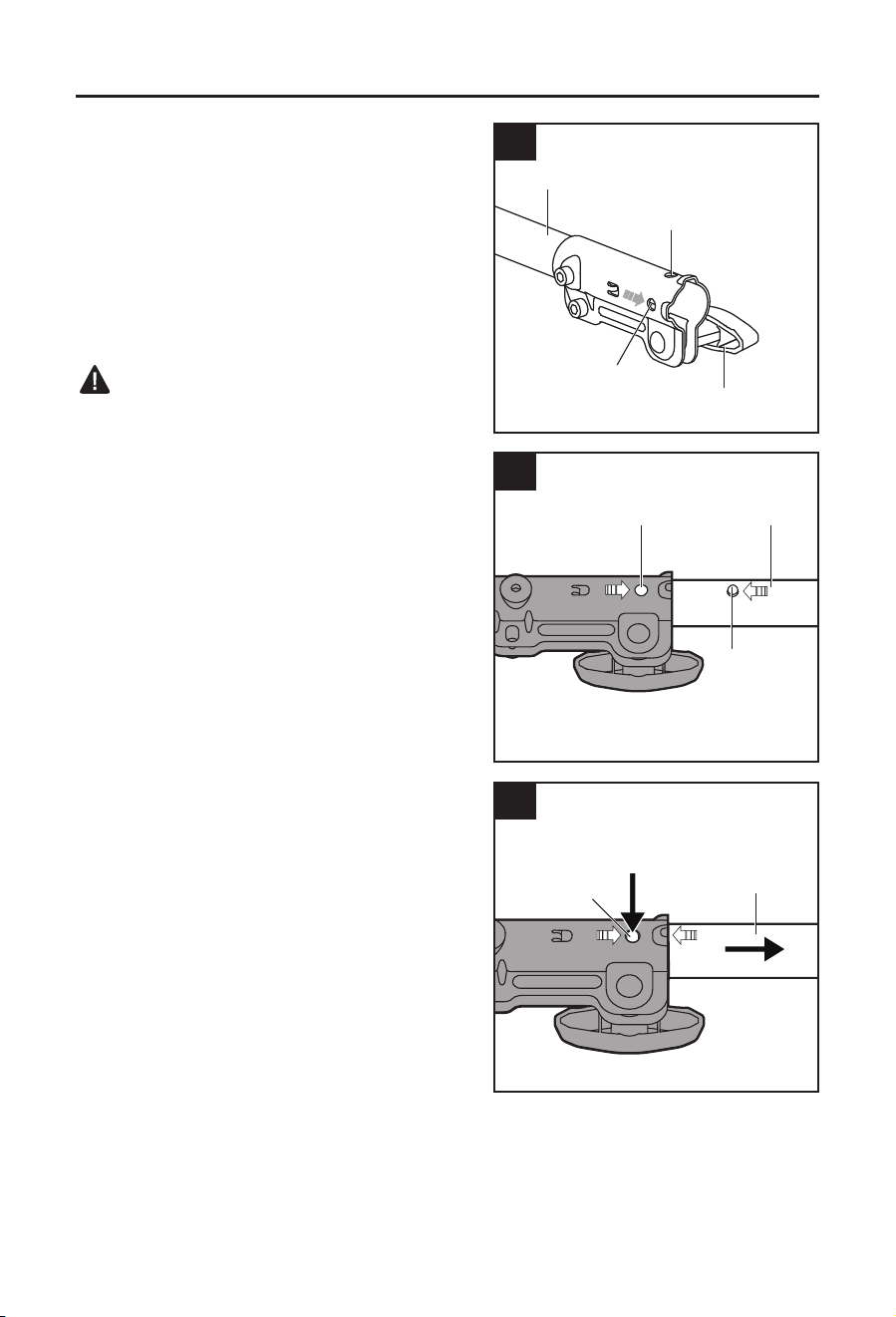
3. To Attach Battery Pack
a. Make sure that the switch is in the OFF
position.
b. Align the raised portion on the battery pack with
the grooves in the power head housing, then
slide the battery pack onto the tool, as shown.
c. Make sure that the latches on the battery pack
snap into place and the battery pack is secured
to the tool before beginning operation.
NOTICE: When placing the battery pack on the
tool, be sure that the raised rib on the battery pack
aligns with the groove on the tool and the latches
snap into place properly. Improper assembly of
the battery pack can cause damage to internal
components.
To Remove Battery Pack
a. Make sure that the switch is in the OFF position.
b. Press the battery-release buttons to release the battery pack.
c. Pull backward on the battery pack to remove it from the tool.
WARNING:
• Battery tools are always in operating condition. Therefore, the ON/OFF switch should always
be in OFF position when the tool is not in use or when carrying the tool at your side.
3
Battery-release
button
12
OPERATING INSTRUCTIONS
4. Starting/Stopping the Power Head
WARNING:
• Never operate the power head without an
attachment. Do not attempt to start the power
head without an attachment.
To start the power head
a. To turn the power head ON, push the lock-off
button (E) to left or right and then depress the
variable-speed trigger switch (F).
b. The variable-speed trigger switch delivers
higher speed with increased trigger pressure
and lower speed with decreased trigger
pressure.
To stop the power head
Release the variable-speed trigger switch (F) to stop the power head.
WARNING
• Always remove the battery pack from the power head during work breaks and after nishing
work.
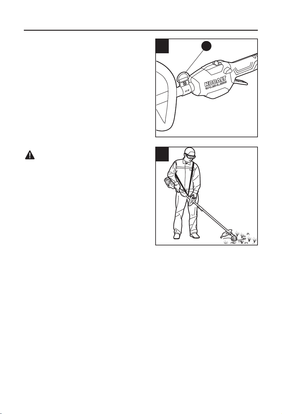
5. Changing Speed Mode
Slide the speed-selector switch (D) to position “1”
for low speed or position “2” for high speed.
NOTE: When in high speed mode, runtime will be
decreased as compared to when the tool is in low
speed mode.
4
E
F
5
D

13
OPERATING INSTRUCTIONS
6. Using Shoulder Strap (sold separately)
For safe and comfortable operation, put the strap
over one of your shoulders and across your back.
a. Remove the battery pack from the power head.
b. Depress the shoulder strap carabiner to open it
and attach it to the shoulder-strap loop (C)
(Fig. 6).
c. Adjust the shoulder strap length to a
comfortable operating position – hold the
trimmer with both hands: one hand on the rear
handle and the other hand on the front-assist
handle (Fig. 7).
WARNING
• When an emergency occurs, take the shoulder
strap off from your shoulder immediately, no
matter what way the strap is on.
6
C
7

14
CARE AND MAINTENANCE
All maintenance should only be carried out by a qualied service technician.
Cleaning
Before cleaning or performing any maintenance, remove the battery pack. For safe and
proper operation, always keep the tool and its ventilation slots clean.
When work has been completed, clean the tool to allow smooth functioning of the tool over
time.
Always use only a soft, dry cloth to clean your tool; never use detergent or alcohol.
Always wear safety goggles when cleaning tools with compressed air.
TROUBLESHOOTING
WARNING: Place the trigger switch (F) in the OFF position and remove the battery before
performing troubleshooting procedures.
PROBLEM POSSIBLE CAUSE CORRECTIVE ACTION
Tool does not work.
Low battery capacity. Charge the battery pack.
The battery pack is not
inserted properly.
Install the battery pack into the tool
correctly.
Motor overheating
Ventilation slots are
obstructed
Clean and clear the ventilation
slots. Do not cover the ventilation
slots with your hand during
operation
WARRANTY
For 5 years from the date of purchase, the circular saw is warranted for the original purchaser
to be free from defects in material and workmanship. This guarantee does not cover damage
due to abuse, normal wear, improper maintenance, neglect, unauthorized repair/alteration, or
expendable parts and accessories expected to become unusable after a reasonable period of
use.
If you think your product meets the above guarantee criteria, please return it to the place of
purchase with valid proof of purchase and the defective product will be repaired or replaced at
no charge. This guarantee gives you specic legal rights, and you may also have other rights
that vary from state to state.
Lowe’s Home Centers LLC.
Mooresville, NC 28117
Printed in China

AS22225
¿Preguntas, problemas, piezas faltantes? Antes de volver a la tienda, llame a nuestro
Departamento de Servicio al Cliente al 888-3KOBALT (888-356-2258), de lunes a
domingo de 8 a. m. a 8 p. m., hora estándar del Este. También puede ponerse en
contacto con nosotros en [email protected].
ADJUNTE SU RECIBO AQUÍ
Número de serie
Fecha de compra
ARTÍCULO #5192324/5129684/5192325
CABEZAL DE POTENCIA
SIN ESCOBILLAS
MODELO #KMH 1024-03
KOBALT y el diseño del logotipo son
marcas comerciales o marcas registradas
de LF, LLC. Todos los derechos reservados.

16
ÍNDICE
Especicaciones del producto ........................................................................16
Contenido del paquete ................................................................................... 17
Información de seguridad ...............................................................................18
Preparación ....................................................................................................22
Instrucciones de ensamblaje ..........................................................................23
Instrucciones de funcionamiento ....................................................................26
Cuidado y mantenimiento ..............................................................................28
Solución de problemas ...................................................................................28
Garantía .........................................................................................................28
ESPECIFICACIONES DEL PRODUCTO
COMPONENTE ESPECIFICACIONES
Voltaje nominal 24 V CC
Temperatura de operación recomendada De 0° C (32 °F) a 40 °C (104 °F)
Temperatura de almacenaje
recomendada
De 0° C (32 °F) a 40 °C (104 °F)
17
CONTENIDO DEL PAQUETE
C
E F
H
J
B D G
I
A
PIEZA DESCRIPCIÓN PIEZA DESCRIPCIÓN
A Perilla mariposa F
Interruptor tipo gatillo de
velocidad variable
B Acoplador G Manija posterior
C Enlazar la correa H Manija de ayuda frontal
D Interruptor de modo de velocidad I Perilla con tornillo
E Botón de bloqueo J
Palanca de bloqueo de la manija
de apoyo
ADVERTENCIA:
• Retire la herramienta del paquete y examínela cuidadosamente. No deseche la caja ni
ningún material de embalaje hasta después de examinar todas las piezas.
• Si falta alguna pieza o si está dañada, no coloque la batería para usar la herramienta hasta
reparar o reemplazar dicha pieza. No seguir esta advertencia podría resultar en lesiones
graves.

18
INFORMACIÓN DE SEGURIDAD
Lea y comprenda completamente este manual antes de intentar ensamblar u operar este
producto. Si tiene preguntas relacionadas con el producto, comuníquese con Servicio al
Cliente al 888-3KOBALT, de lunes a domingo, de 8 a.m. a 8 p.m., hora estándar del Este.
También puede ponerse en contacto con nosotros en [email protected].
ADVERTENCIA:
• La operación de cualquier herramienta eléctrica puede arrojar objetos extraños a los
ojos y, de esta manera, causar graves daños oculares. Use siempre lentes o gafas de
seguridad con protecciones laterales y, cuando sea necesario, un protector facial que cubra
todo el rostro antes de comenzar a operar una herramienta eléctrica. Recomendamos
usar una máscara de seguridad de visión amplia sobre los lentes o gafas de seguridad
con protecciones estándar. Use siempre lentes de protección que cumplan con la norma
ANSI Z87.1.
• Parte del polvo causado por el lijado eléctrico, el serruchado, la trituración, el taladro y
otras actividades de construcción contiene sustancias químicas que, según el estado de
California, causan cáncer, defectos congénitos u otros daños reproductivos. Estos son
algunos ejemplos de dichos productos químicos:
– Plomo de pinturas a base de plomo
– Sílice cristalina de ladrillos, cemento y otros productos de mampostería
– Arsénico y cromo de madera tratada con químicos
• El riesgo que corre debido a la exposición a estos químicos varía según la frecuencia con
que realiza este tipo de trabajo. Para disminuir la exposición a estos productos químicos,
realice lo siguiente:
– Trabaje en un área bien ventilada.
– Trabaje con equipo de seguridad aprobado, como las mascarillas antipolvo
especialmente diseñadas para ltrar partículas microscópicas.
– Evite el contacto prolongado con el polvo producido por el uso de lijas, sierras,
trituradoras, taladros eléctricos y otras actividades de construcción. Use ropa protectora
y lave todas las áreas expuestas del cuerpo con agua y jabón. El ingreso de polvo a la
boca o a los ojos o su contacto con la piel puede provocar la absorción de productos
químicos dañinos.
Conozca la herramienta
Para operar esta herramienta, lea cuidadosamente este manual y todas las etiquetas
adheridas a la herramienta antes de usarla. Guarde este manual para referencia futura.
Importante
Solo un técnico calicado puede reparar esta herramienta.
Lea detenidamente todas las instrucciones
19
INFORMACIÓN DE SEGURIDAD
Algunos de los siguientes símbolos pueden aparecer en esta herramienta. Obsérvelos y
aprenda su signicado. La interpretación correcta de estos símbolos le permitirá utilizar la
herramienta de manera más ecaz y segura.
SÍMBOLO DEFINICIÓN SÍMBOLO DEFINICIÓN
V Voltios n
0
Velocidad en vacío
Corriente continua /min o RPM Revoluciones por minuto
Peligro, advertencia o
precaución. Signica
"¡Atención! Su seguridad está
en riesgo".
Para reducir el riesgo de
lesiones, el usuario debe leer
el manual de instrucciones.
Advertencias generales sobre la seguridad en el manejo de herramientas eléctricas
ADVERTENCIA
• Lea todas las advertencias de seguridad, las instrucciones, las ilustraciones y las
especicaciones que se incluyen para esta herramienta eléctrica. No cumplir con todas
las instrucciones que se detallan a continuación podría provocar descargas eléctricas,
incendios o lesiones graves.
Guarde todas las advertencias e instrucciones para referencia futura
• El término “herramienta eléctrica” que aparece en las advertencias hace referencia a la
herramienta eléctrica que se conecta a la línea principal (con cable) o a la herramienta
eléctrica que funciona a batería (inalámbrica).
Seguridad en el área de trabajo
• Mantenga el área de trabajo limpia y bien iluminada. Las áreas oscuras o desordenadas
propician los accidentes.
• No utilice herramientas eléctricas en atmósferas en las que exista riesgo de
explosión, por ejemplo, en presencia de líquidos inamables, gases o polvo. Las
herramientas eléctricas producen chispas que podrían encender el polvo o humo.
• Mantenga a los niños y a otras personas alejados mientras utiliza una herramienta
eléctrica. Las distracciones pueden hacerle perder el control.
Seguridad eléctrica
• Los enchufes de las herramientas eléctricas deben encajar en el tomacorriente. No
modique el enchufe de ninguna manera. No utilice ningún enchufe adaptador con
herramientas eléctricas con puesta a tierra. Los enchufes originales y que encajan
adecuadamente en los tomacorrientes reducen el riesgo de descarga eléctrica.
• Evite el contacto del cuerpo con supercies conectadas a tierra, como tuberías,
radiadores, extractores o refrigeradores. Si su cuerpo tiene contacto a tierra, corre
mayor riesgo de sufrir una descarga eléctrica.
• No exponga las herramientas eléctricas a la lluvia o a condiciones de humedad.
Si ingresa agua en una herramienta eléctrica, aumenta el riesgo de sufrir una descarga
eléctrica.

20
INFORMACIÓN DE SEGURIDAD
• No maltrate el cable. Nunca use el cable para transportar, jalar ni desenchufar la
herramienta eléctrica. Mantenga el cable alejado del calor, el aceite, los bordes
losos o las piezas en movimiento. Los cables dañados o enredados aumentan el riesgo
de descarga eléctrica.
• Si opera una herramienta eléctrica en exteriores, use la extensión eléctrica apropiada
para el uso en exteriores. Usar un cable apto para exteriores reduce el riesgo de sufrir
una descarga eléctrica.
• Si debe utilizar una herramienta eléctrica en un área húmeda, use un suministro
protegido con un interruptor de circuito de falla de puesta a tierra (GFCI, por sus
siglas en inglés). Usar un GFCI disminuye el riesgo de recibir una descarga eléctrica.
Seguridad personal
• Manténgase alerta, preste atención a lo que hace y utilice el sentido común cuando
utilice una herramienta eléctrica. No utilice una herramienta eléctrica si está cansado
o bajo los efectos de drogas, alcohol o medicamentos. Un momento de desatención
mientras opera herramientas eléctricas puede provocar lesiones personales graves.
• Use un equipo de protección personal. Use siempre lentes de protección. Los
equipos de protección, como mascarillas antipolvo, zapatos de seguridad antideslizantes,
cascos protectores o auriculares de seguridad, utilizados para las condiciones adecuadas,
disminuyen el riesgo de lesiones personales.
• Evite un arranque accidental. Asegúrese de que el interruptor esté en la posición de
apagado antes de conectar la herramienta a la fuente de alimentación o al paquete de
baterías, o antes de levantarla o transportarla. Transportar herramientas eléctricas con el
dedo en el interruptor o enchufar herramientas eléctricas que tienen el interruptor encendido
aumenta las posibilidades de sufrir accidentes.
• Retire todas las llaves de ajuste o llaves inglesas antes de encender la herramienta
eléctrica. Dejar una llave inglesa o una llave conectada a una pieza giratoria de la
herramienta eléctrica puede provocar lesiones personales.
• No se extienda demasiado. Mantenga una postura y un equilibrio adecuados en
todo momento. Esto permite controlar mejor la herramienta eléctrica ante situaciones
inesperadas.
• Use ropa adecuada. No use ropa holgada ni joyas. Mantenga el cabello y la ropa
alejados de las piezas en movimiento. La ropa holgada, las joyas o el cabello largo
pueden quedar atrapados en las piezas en movimiento.
• Si se proporcionan dispositivos para la conexión de instalaciones de extracción y
recolección de polvo, asegúrese de que se conecten y se usen de manera adecuada.
La recolección de polvo puede disminuir los peligros relacionados con el polvo.
• No permita que la familiaridad obtenida por el uso frecuente de herramientas
ocasione el descuido y olvido de los principios de seguridad en el manejo de
herramientas. Un descuido puede ocasionar una lesión grave en cuestión de segundos.
Uso y cuidado de las herramientas eléctricas
• No fuerce la herramienta eléctrica. Use la herramienta eléctrica adecuada para la
tarea. La herramienta eléctrica adecuada realizará un trabajo de mejor calidad y más
seguro, al ritmo para el cual se diseñó.
• No utilice la herramienta eléctrica si no la puede encender o apagar con el interruptor.
Cualquier herramienta eléctrica que no pueda controlarse con el interruptor es peligrosa y
debe repararse.

21
INFORMACIÓN DE SEGURIDAD
• Desconecte el enchufe de la fuente de alimentación o retire el paquete de baterías
de la herramienta eléctrica (si es posible) antes de realizar cualquier ajuste, cambiar
accesorios o almacenar herramientas eléctricas. Estas medidas de seguridad
preventivas reducen el riesgo de provocar arranques accidentales de la herramienta
eléctrica.
• Almacene las herramientas eléctricas que no estén en uso fuera del alcance de
los niños y no permita que personas que no conozcan cómo usar la herramienta o
estas instrucciones la utilicen. Las herramientas eléctricas son peligrosas en manos de
usuarios sin capacitación.
• Realice mantenimiento a las herramientas eléctricas y a los accesorios. Revise si
hay piezas móviles desalineadas o trabadas, si hay piezas rotas y cualquier otra
condición que pueda afectar el funcionamiento de la herramienta eléctrica. Si se
daña la herramienta eléctrica, hágala reparar antes de usarla. Muchos accidentes son
producto del mantenimiento deciente de las herramientas eléctricas.
• Mantenga las herramientas de corte aladas y limpias. Las herramientas de corte que
se mantienen adecuadamente con sus bordes de corte alados son menos propensas a
trabarse y son más fáciles de controlar.
• Use la herramienta eléctrica, los accesorios, las brocas, etc. de acuerdo con estas
instrucciones, considerando las condiciones de trabajo y la tarea que desea realizar.
Si la herramienta eléctrica se usa en operaciones para las cuales no se diseñó, podría crear
una situación de peligro.
• Mantenga los mangos y las supercies de agarre secas, limpias y sin aceite ni grasa.
Las manijas y las supercies de agarre resbaladizas no permiten manipular ni controlar la
herramienta de forma segura en situaciones inesperadas.
Uso y cuidado de herramientas a batería
• Recargue solo con el cargador especicado por el fabricante. Un cargador adecuado
para un tipo de paquete de baterías puede causar un riesgo de incendio si se usa con otro
paquete de baterías.
• Use herramientas eléctricas solo con paquetes de baterías designados
especícamente. El uso de cualquier otro paquete de baterías puede crear un riesgo de
lesión e incendio.
• Cuando no se use el paquete de baterías, aléjelo de objetos metálicos, como
sujetapapeles, monedas, llaves, clavos, tornillos u otros objetos metálicos pequeños
que pudieran crear una conexión entre los terminales. El cortocircuito de los terminales
de la batería puede causar quemaduras o un incendio.
• En condiciones de maltrato, es posible que salga líquido de la batería. Evite el
contacto. Si se produce un contacto accidental, enjuague con agua. Si el líquido
entra en contacto con los ojos, solicite atención médica. El líquido que sale de la
batería puede provocar irritación o quemaduras.
• No utilice un paquete de baterías ni una herramienta si están dañadas o modicadas.
Las baterías dañadas o modicadas pueden mostrar una conducta impredecible que podría
provocar incendios, explosiones o riesgo de lesiones.
• No exponga el paquete de baterías ni la herramienta al fuego ni a temperaturas
excesivas. La exposición al fuego o a temperaturas por encima de los 130 °C (265 °F)
podría causar una explosión.
• Siga todas las instrucciones de carga y no cargue el paquete de baterías ni la
herramienta fuera del rango de temperatura especicado en las instrucciones.
Realizar una carga inadecuada o a temperaturas fuera del rango especicado podría dañar
la batería y aumentar el riesgo de incendio.

22
INFORMACIÓN DE SEGURIDAD
Reparación
• Permita que solo una persona capacitada repare la herramienta eléctrica y que utilice
únicamente piezas de repuesto idénticas a las de fábrica. Esto garantizará que se
mantenga la seguridad de la herramienta eléctrica.
• Nunca realice el mantenimiento de los paquetes de baterías dañados. Solo el
fabricante o los proveedores de servicio autorizados pueden realizarles mantenimiento.
Advertencias adicionales
• Use solamente los paquetes de baterías y los cargadores que se indican a
continuación:
PAQUETE DE BATERÍAS CARGADOR
KB 224-03; KB 424-03; KB 524-03;
KB 624-03; KXB 424-03; KXB 824-03
KRC 2445-03; KCH 2401-03; KCH 2411-03;
KRC 2490-03; KRC 2024-03; KDPC 124-03
• Este cabezal de potencia se puede utilizar solo con los siguientes accesorios:
TIPO DE SUJECIÓN NÚMERO DEL MODELO
Orilladora KMS 1040-03
Bordeadora KEG 1040-03
Desmalezadora: KMB 1040-03
Separador KMD 1040-03
Podadora de altura KMPS 1040-03
Podadora de arbustos de bastón KMPH 1040-03
Consulte el manual del operador de su orilladora KOBALT KMS 1040-03 para su uso con
este cabezal de potencia.
Consulte el manual del operador de su bordeadora KOBALT KEG 1040-03 para su uso
con este cabezal de potencia.
Consulte el manual del operador de su desmalezadora KOBALT KMB 1040-03 para su
uso con este cabezal de potencia.
Consulte el manual del operador de su separador KOBALT KMD 1040-03 para su uso
con este cabezal de potencia.
Consulte el manual del operador de su podadora de altura KOBALT KMPS 1040-03 para
su uso con este cabezal de potencia.
Consulte el manual del operador de su podadora de arbustos KOBALT KMPH 1040-03
para su uso con este cabezal de potencia.
GUARDE ESTAS INSTRUCCIONES

23
PREPARACIÓN
Conozca su cabezal de potencia
Antes de intentar usar la cabezal de potencia, familiarícese con todas las características de
funcionamiento y los requisitos de seguridad.
ADVERTENCIA:
• Sea cuidadoso, incluso si está familiarizado con la herramienta. Recuerde que un
momento de descuido es suciente para causar lesiones graves. Antes de intentar utilizar
una herramienta, asegúrese de familiarizarse con todas las funciones de operación e
instrucciones de seguridad.
• No intente modicar esta herramienta ni crear accesorios que no sean los recomendados
para esta. Cualquier alteración o modicación se considera un uso indebido y podría causar
una situación peligrosa que resulte en lesiones graves.
24
INSTRUCCIONES DE ENSAMBLAJE
ADVERTENCIA
• Lea y comprenda todo el Manual del operador de cada accesorio opcional utilizado con
este cabezal de potencia y siga todas las advertencias e instrucciones. No seguir todas
las instrucciones podría resultar en descargas eléctricas, incendio y/o lesiones personales
graves.
• Este cabezal de potencia de 24 V está diseñado para usarse solo con los modelos de
accesorios que se especican en este Manual del operador. El uso de otros accesorios no
autorizados podría causar lesiones personales graves o daños materiales.
• Algunos accesorios tienen requisitos especícos relacionados con la seguridad. Siempre
preste especial atención a estas instrucciones en el manual que viene con cada accesorio.
• Nunca instale, quite ni ajuste ningún accesorio si el cabezal de potencia está funcionando
o con la batería instalada. No detener el motor y retirar la batería puede causar lesiones
personales graves. NUNCA OPERE EL CABEZAL DE POTENCIA SIN UN ACCESORIO.
ADVERTENCIA
• Siempre retire el paquete de baterías del producto cuando no esté en uso o cuando esté
ensamblando las piezas, realizando ajustes o limpiándolo.
1. Instalación y extracción del accesorio del
cabezal de potencia
Instalación del accesorio
a. Retire el paquete de baterías.
b. Aoje la perilla de mariposa (A) (Fig. 1a).
c. El cabezal de potencia tiene dos ranuras en
el acoplador (B), SOLO la ranura 1 se usa
para conectar accesorios: KMS 1040-03, KEG
1040-03, KMB 1040-03, KMD 1040-03, KMPS
1040-03 y KMPH 1040 -03.
d. Alinee el pasador con resorte del accesorio con
la ranura del acoplador (B) y empuje el eje del
accesorio en el eje del cabezal de potencia
hasta que el pasador salga de la ranura y
escuche un sonido de “clic” al mismo tiempo
(Fig. 1b).
e. Jale el vástago en el accesorio para vericar
que esté rmemente asegurado en el
acoplador (B).
f. Ajuste rmemente la perilla mariposa (A).
1a
B
A
Acanaladura 1
Acanaladura 2
B
1b
Acanaladura
Pasador
25
INSTRUCCIONES DE ENSAMBLAJE
Extracción del accesorio
a. Retire el paquete de baterías.
b. Aoje la perilla mariposa (A).
c. Presione hacia abajo el pasador activado por
resorte y extraiga el eje del accesorio del
acoplador (Fig. 1c).
2. Montaje y ajuste de la manija delantera
a. Retire el paquete de baterías del cabezal de
potencia.
b. Retire la perilla con tornillo (l) y la palanca de
ajuste (J) de la manija delantera (I).
c. Monte la manija delantera en el eje, como se
muestra en la Fig. 2a.
d. Inserte la palanca de ajuste en la manija
delantera y, luego, apriete la perilla con tornillo.
Asegúrese de que la manija delantera mire
hacia arriba, de modo que apunte hacia la
manija trasera. (Fig. 2b).
e. Baje la palanca de ajuste para asegurar la
manija delantera sobre el eje, de modo que
no pueda moverse sobre el eje durante el
funcionamiento.
Cómo ajustar la posición de la manija delantera
La manija debe ajustarse de modo que el brazo
que sostiene la manija delantera esté recto cuando
se usa el cabezal de potencia.
Para ajustar la posición de la manija delantera (C),
levante la palanca de ajuste de modo que la manija
delantera pueda moverse a la posición deseada
a lo largo del eje. Baje la palanca de ajuste de
modo que la manija no pueda moverse sobre el eje
durante el funcionamiento.
ADVERTENCIA:
• Hay una etiqueta en el eje del cabezal de
potencia para limitar la distancia de ajuste de la manija delantera para cumplir con los
requisitos de la distancia de la manija delantera y trasera. Nunca ajuste la manija delantera
más allá de la posición de la etiqueta.
• Nunca opere la herramienta si la manija delantera no está bien colocada en su lugar.
2a
J
H
I
2b
1c
Pasador
26
INSTRUCCIONES DE ENSAMBLAJE
3. Para colocar el paquete de baterías
a. Asegúrese de que el interruptor esté en la
posición OFF.
b. Alinee la parte elevada del paquete de baterías
con las ranuras de la carcasa del cabezal de
potencia, luego deslice el paquete de baterías
sobre la herramienta, como se muestra.
c. Asegúrese de que los pestillos del paquete de
baterías encajen en su lugar y que el paquete
de baterías esté jo en la herramienta antes de
comenzar la operación.
AVISO: cuando coloque el paquete de baterías
en la herramienta, asegúrese de que la varilla elevada del paquete de baterías se alinee con
la ranura de la herramienta y que los pestillos encajen en su lugar de manera correcta. El
ensamblaje inadecuado del paquete de baterías puede provocar daños a los componentes
internos.
Cómo retirar el paquete de baterías
a. Asegúrese de que el interruptor esté en la posición OFF.
b. Presione los botones de liberación de la batería para poder retirar el paquete de baterías.
c. Jale el paquete de baterías hacia atrás para retirarlo de la herramienta.
ADVERTENCIA:
• Las herramientas con batería siempre están en condiciones de operación. Por lo tanto,
el interruptor de encendido y apagado debe estar siempre en la posición OFF cuando la
herramienta no esté en uso, o cuando transporte la herramienta a su lado.
3
Botón de liberación
de la batería

27
INSTRUCCIONES DE FUNCIONAMIENTO
4. Arranque/parada del cabezal de potencia
ADVERTENCIA:
• Nunca opere el cabezal de potencia sin un
accesorio. No intente encender el cabezal de
potencia sin un accesorio.
Para iniciar el cabezal de potencia
a. Para encender el cabezal de potencia, presione
el botón de bloqueo (E) a la izquierda o
derecha y luego, presione el interruptor tipo
gatillo de velocidad variable (F).
b. El interruptor tipo gatillo de velocidad variable
proporciona mayor velocidad con mayor presión en el gatillo y menor velocidad con menor
presión en el gatillo.
Para detener el cabezal de potencia
Suelte el interruptor tipo gatillo de velocidad variable (F) para detener el cabezal de potencia.
ADVERTENCIA
• Siempre retire el paquete de baterías del cabezal de potencia en los descansos y tras
nalizar los trabajos.
5. Cambio de modos de velocidad
Deslice el selector del modo de velocidad (D) a la
posición “1” para el modo de baja velocidad o a la
posición “2” para el modo de alta velocidad.
NOTA: cuando está en modo de alta velocidad, el
tiempo de ejecución se reducirá en comparación
con cuando la herramienta está en modo de baja
velocidad.
5
D
4
E
F
28
INSTRUCCIONES DE FUNCIONAMIENTO
6. Uso de la correa para el hombro (se vende
por separado)
Para una operación segura y cómoda, coloque la
correa sobre uno de sus hombros y a través su
espalda.
a. Retire el paquete de baterías del cabezal de
potencia.
b. Presione el mosquetón de la correa para el
hombro para abrirlo y fíjelo al enganche de la
correa para el hombro (C) (Fig. 6).
c. Ajuste la longitud de la correa para el hombro a
una posición de operación cómoda: sostenga
la recortadora con ambas manos: una mano en
el mango trasero y la otra mano en el mango
auxiliar delantero (Fig. 7).
ADVERTENCIA
• Cuando ocurra una emergencia, quítese
la correa para el hombro del hombro
inmediatamente, sin importar de qué manera
esté puesta la correa.
6
C
7

29
CUIDADO Y MANTENIMIENTO
Todo el mantenimiento debe estar exclusivamente a cargo de un técnico calicado.
Limpieza
Antes de realizar una limpieza o mantenimiento, retire el paquete de baterías. Para
un uso seguro y adecuado, siempre mantenga limpias la herramienta y sus ranuras de
ventilación.
Cuando haya terminado el trabajo, limpie la herramienta para permitir un buen funcionamiento
de la herramienta a lo largo del tiempo.
Siempre use solo un paño suave y seco para limpiar la herramienta; nunca use detergente ni
alcohol.
Siempre use gafas de seguridad al limpiar herramientas con aire comprimido.
SOLUCIÓN DE PROBLEMAS
ADVERTENCIA: coloque el interruptor tipo gatillo (F) en la posición de APAGADO y retire
las baterías antes de realizar los procedimientos de solución de problemas.
PROBLEMA CAUSA POSIBLE ACCIÓN CORRECTIVA
La herramienta no
funciona.
La capacidad de la batería
es baja.
Cargue el paquete de baterías.
El paquete de baterías
no está insertado
correctamente.
Instale correctamente el paquete de
baterías en la herramienta.
El motor se
sobrecalentó
Las ranuras de ventilación
están obstruidas
Limpie y despeje las ranuras de
ventilación. No cubra los conductos
de ventilación con la mano durante
el funcionamiento
GARANTÍA
La sierra circular está garantizada contra defectos de fabricación en materiales y mano de
obra por 5 años desde la fecha de compra para el comprador original. Esta garantía no cubre
daños por uso indebido, desgaste normal, mantenimiento inadecuado, negligencia, reparación
o alteración no autorizadas, ni piezas o accesorios desechables cuya inutilidad es esperable
después de un período de uso razonable.
Si considera que el producto cumple con los términos de garantía mencionados arriba,
devuélvalo al lugar donde lo compró con un comprobante de compra válido y el producto
defectuoso se reparará o reemplazará sin cargo. Esta garantía le otorga derechos legales
especícos, pero también podría tener otros derechos que varían según el estado.
Lowe’s Home Centers LLC.
Mooresville, NC 28117
Impreso en China


SM21455
Questions, problems, missing parts? Before returning to your retailer, call our customer
service department at 888-3KOBALT (888-356-2258), 8 a.m. - 8 p.m., EST,
Monday - Sunday. You could also contact us at [email protected].
ATTACH YOUR RECEIPT HERE
Serial Number Purchase Date
Español p. 17
KOBALT and logo design are trademarks or
registered trademarks of LF, LLC. All rights reserved.
ITEM #3809898/4132850/4665016 /5129684/5192325
STRING TRIMMER
ATTACHMENT
MODEL #KMS 1040-03

2
TABLE OF CONTENTS
Product Specications ......................................................................................2
Package Contents ............................................................................................3
Safety Information ............................................................................................ 4
Preparation .......................................................................................................7
Operating Instructions ...................................................................................... 8
Care and Maintenance ...................................................................................13
Troubleshooting.............................................................................................. 17
Warranty ......................................................................................................... 17
PRODUCT SPECIFICATIONS
COMPONENT SPECIFICATION
Cutting Mechanism Bump Head
Cutting-Line Type 0.08 in. twisted nylon line
Cutting Width 13 in. (33cm) / 15 in. (38 cm)
Operating temperature 32°F (0°C) - 104°F (40°C)
Storage temperature 32°F (0°C) - 104°F (40°C)
3
PACKAGE CONTENTS
A
D
E
B
C
G
H
F
PART DESCRIPTION PART DESCRIPTION
A Bump head E Trimmer head
B Line-cutting blade F Hex Key
C Guard G Bolt (2)
D
Trimmer attachment shaft H Spring washer (2)
WARNING
• Remove the tool from the package and examine it carefully. Inspect the tool carefully to
make sure that no breakage or damage occurred during shipping. If any parts are damaged
or missing, please return the product to the place of purchase. Do not discard the carton or
any packaging material until all parts have been examined.
• If any part of the tool is missing or damaged, do not attach the battery to use the tool until
the part has been repaired or replaced. Failure to heed this warning could result in serious
injury.

4
SAFETY INFORMATION
Please read and understand this entire manual before attempting to assemble or operate
this product. If you have any questions regarding the product, please call customer service at
888-3KOBALT (888-356-2258), 8 a.m. - 8 p.m., EST, Monday - Sunday. You could also contact
us at [email protected].
WARNING
• The operation of any power tool can result in foreign objects being thrown into your eyes,
which can result in severe eye damage. Before beginning power-tool operation, always wear
safety goggles or safety glasses with side shields and a full-face shield, when needed. We
recommend using a wide vision safety mask over eyeglasses or standard safety glasses
with shields. Always use eye protection marked to comply with ANSI Z87.1.
• Some dust created by power sanding, sawing, grinding, drilling, and other construction
activities contains chemicals known to the state of California to cause cancer, birth defects,
or other reproductive harm. Some examples of these chemicals are:
– Lead from lead-based paints
– Crystalline silica from bricks, cement, and other masonry products
– Arsenic and chromium from chemically-treated lumber
• Your risk from these exposures varies, depending upon how often you do this type of work.
To reduce your exposure to these chemicals:
– Work in a well-ventilated area.
– Work with approved safety equipment, such as dust masks that are specially designed to
lter out microscopic particles.
– Avoid prolonged contact with dust from power sanding, sawing, grinding, drilling, and
other construction activities. Wear protective clothing and wash exposed areas with soap
and water. Allowing dust to get into your mouth or eyes or to lie on the skin may promote
absorption of harmful chemicals.
Know the Tool
To operate this tool, carefully read this manual and all labels afxed to the tool before using it.
Keep this manual available for future reference.
Important
This tool should be serviced only by a qualied service technician.
Read All Instructions Thoroughly
5
SAFETY INFORMATION
Some of the following symbols may be used on this tool. Please study them and their meaning.
Proper interpretation of these symbols will allow you to operate the tool better and more safely.
SYMBOL DEFINITION SYMBOL DEFINITION
V Volts n
0
No-load speed
Direct current RPM Revolutions per Minute
A danger, warning, or caution.
It means ‘Attention! Your safety
is involved.’
To reduce the risk of injury, user
must read instruction manual.
Wear eye, ear and head
protection.
Do not expose to rain.
IMPORTANT SAFETY INSTRUCTIONS
WARNING
• When using electric trimmers, basic safety precautions should always be followed to reduce
the risk of re, electric shock, and personal injury, including the following:
READ ALL INSTRUCTIONS
DANGER
• Do not rely on the tool’s insulation against electric shock. To reduce the risk of
electrocution, never operate the tool in the vicinity of any wires or cables which may
carry electric current.
Grass Trimmer Safety Warnings
• Do not use the machine in bad weather conditions, especially when there is a risk of
lightning. This decreases the risk of being struck by lightning.
• Thoroughly inspect the area for wildlife where the machine is to be used. Wildlife may
be injured by the machine during operation.
• Thoroughly inspect the area where the machine is to be used and remove all stones,
sticks, wires, bones, and other foreign objects. Thrown objects can cause personal
injury.
• Before using the machine, always visually inspect to see that the cutter or blade and
the cutter or blade assembly are not damaged. Damaged parts increase the risk of injury.
• Follow instructions for changing accessories. Improperly tightened blade securing nuts
or bolts may either damage the blade or result in it becoming detached.
• Wear eye, ear, head and hand protection. Adequate protective equipment will reduce
personal injury by ying debris or accidental contact with the cutting line or blade.
• While operating the machine, always wear non-slip and protective footwear. Do not
operate the machine when barefoot or wearing open sandals. This reduces the chance
of injury to the feet from contact with the moving cutters or lines.

6
SAFETY INFORMATION
• While operating the machine, always wear long trousers. Exposed skin increases the
likelihood of injury from thrown objects.
• Keep bystanders away while operating the machine. Thrown debris can result in serious
personal injury.
• Always use two hands when operating the machine. Holding the machine with both
hands will avoid loss of control.
• Hold the machine by the insulated gripping surfaces only, because the cutting line or
blade may contact hidden wiring. Cutting line or blades contacting a “live” wire may make
exposed metal parts of the machine “live” and could give the operator an electric shock.
• Always keep proper footing and operate the machine only when standing on the
ground. Slippery or unstable surfaces may cause a loss of balance or control of the
machine.
• Do not operate the machine on excessively steep slopes. This reduces the risk of loss
of control, slipping and falling which may result in personal injury.
• When working on slopes, always be sure of your footing, always work across the face
of slopes, never up or down and exercise extreme caution when changing direction.
This reduces the risk of loss of control, slipping and falling which may result in personal
injury.
• Keep all parts of the body away from the cutter, line or blade when the machine is
operating. Before you start the machine, make sure the cutter, line or blade is not
contacting anything. A moment of inattention while operating the machine may result in
injury to yourself or others.
• Do not operate the machine above waist height. This helps prevent unintended cutter or
blade contact and enables better control of the machine in unexpected situations.
• When cutting brush or saplings that are under tension, be alert for spring back. When
the tension in the wood bres is released, the brush or sapling may strike the operator and/
or throw the machine out of control.
• Use extreme caution when cutting brush and saplings. The slender material may catch
the blade and be whipped toward you or pull you off balance.
• Maintain control of the machine and do not touch cutters, lines or blades and other
hazardous moving parts while they are still in motion. This reduces the risk of injury
from moving parts.
• Carry the machine with the machine switched off and away from your body. Proper
handling of the machine will reduce the likelihood of accidental contact with a moving cutter,
line or blade.
• Only use replacement cutters, lines, cutting heads and blades specied by the
manufacturer. Incorrect replacement parts may increase the risk of breakage and injury.
• When clearing jammed material or servicing the machine, make sure the switch is
off and the battery pack is removed. Unexpected starting of the machine while clearing
jammed material or servicing may result in serious personal injury.
• Use only with 40V Power Head KMH 1040-03 or 24V Power Head KMH 1024-03.
NOTE: see operator’s manual for your KOBALT power head (KMH 1040-03 and
KMH 1024-03) for specic safety rules.
SAVE THESE INSTRUCTIONS!

7
PREPARATION
Know Your String Trimmer
This product requires assembly. Carefully lift the tool from the carton and place it on a level
work surface. Before attempting to use the string trimmer attachment, familiarize yourself with
all of its operating features and safety requirements.
WARNING
• Do not allow familiarity with the tool to cause carelessness. Remember that one careless
moment is enough to cause severe injury. Before attempting to use any tool, be sure to
become familiar with all of the operating features and safety instructions.
• Do not attempt to modify this tool or create accessories not recommended for use with this
tool. Any such alteration or modication is misuse and could result in a hazardous condition
leading to possible serious personal injury.
8
ASSEMBLY INSTRUCTIONS
WARNING: This product requires assembly. To reduce the risk of injury to persons, never
operate without the guard in place. The guard must always be on the tool to protect the user.
1. Mounting the Guard
WARNING
• Install the guard before the attachment is
connected to the power head.
• To reduce the risk of injury to persons, do not
operate without guard in place.
a. Loosen the two bolts (G) in the guard with the
supplied hex key (F). Remove the bolts and
spring washers (H) from the guard (C)
(Fig. 1a).
b. Lift the trimmer head (E) and face it downward;
align the two mounting holes in the guard with
the two assembly holes in the base of the shaft.
Make sure that the inner surface of the guard
faces towards the trimmer head (Fig. 1b).
c. Use the supplied hex key to secure the guard in
place with the washers and bolts.
1a
H
C
G
G
H
E
C
1b
9
ASSEMBLY INSTRUCTIONS
2. Connecting the String Trimmer Attachment
to the Power Head (KMH 1040-03 and
KMH 1024-03)
Installing the attachment
a. Remove the battery pack from the power head.
b. Loosen the wing knob on the power-head shaft
(Fig. 2a).
c. The power head has two grooves on the
coupler, ONLY the groove 1 is used to connect
this attachment.
WARNING
• Do not install this attachment with groove
2, which may cause personal injury during
operation.
d. Align the spring-loaded pin on the attachment
with the groove on the coupler and push the
attachment shaft into the power head shaft until
the pin pops out of the groove and you hear an
audible “click” sound at the same time (Fig. 2b).
e. Pull the shaft of the attachment to verify that it
is securely locked into the coupler.
f. Tighten the wing knob securely.
Removing the attachment
a. Remove the battery pack from the power head.
b. Loosen the wing knob.
c. Press down the spring-loaded pin and pull the
attachment shaft out of the coupler (Fig. 2c).
2b
Groove
Pin
Attachment
shaft
2c
Attachment
shaft
Pin
2a
Power-head shaft
Groove 2
Wing knob
Groove 1

10
OPERATING INSTRUCTIONS
3. Holding the String Trimmer
WARNING
• Dress properly to reduce the risk of injury when
operating this tool.
Do not wear loose clothing or jewelry. Wear eye
and ear/hearing protection. Wear heavy, long pants,
boots and gloves. Do not wear short pants and
sandals or go barefoot.
Before operating the unit, stand in the operating
position and check that:
• The operator is wearing eye protection and
proper clothing.
• One arm is slightly bent. The hand of that arm is holding the rear handle.
• The other arm is straight. The hand of that arm is holding the front-assist handle.
• The trimmer head is parallel to the ground and easily contacts the material to be cut without
the operator having to bend over.
4. To Start/Stop the String Trimmer
See “STARTING/STOPPING THE POWER HEAD” section in the KMH 1040-03 power head
operator’s manual.
5. Using the String Trimmer
Tips for best trimming results (Fig. 5a)
WARNING
• Check for damaged/worn parts before each use.
• To avoid serious personal injury, wear goggles
or safety glasses at all times when operating
this unit. Wear a face mask or dust mask in
dusty locations. Wear proper clothing and
footwear during operation to reduce the risk of
injury that may be caused by ying debris.
• Clear the area to be cut before each use.
Remove all objects, such as rocks, broken
glass, nails, wire, or string that can be thrown or become entangled in the cutting
attachment. Clear the area of children, bystanders, and pets. At a minimum, keep all
children, bystanders, and pets at least 100 ft. (30.5 m) away. There still may be risk to
bystanders from thrown objects.
• Bystanders should be encouraged to wear eye protection. If you are approached, stop the
motor and cutting attachment immediately.
• The correct angle for the cutting attachment is parallel to the ground.
3
5a
Direction of
rotation
Best cutting
area
Dangerous
cutting area
11
OPERATING INSTRUCTIONS
• This string trimmer allows you to rest the bump head (A) on the ground for more comfortable
operation.
• Do not force the trimmer. Allow the very tip of the line to do the cutting (especially along
walls). Cutting with more than the tip will reduce cutting efciency and may overload the
motor.
• The cutting height is determined by the distance of the cutting line from the lawn surface.
• Grass over 8 in. (200 mm) should be cut by working from top to the bottom in small
increments to avoid premature line wear or motor drag.
• Slowly move the trimmer into and out of the area being cut, maintaining the cutting head
position at the desired cutting height. This movement can be either a forward-backward
motion or a side-to-side motion. Cutting shorter lengths produces best results.
• Trim only when grass and weeds are dry.
• Wire and picket fences can cause extra string wear or breakage. Stone and brick walls,
curbs, and wood may wear strings rapidly.
• Avoid trees and shrubs. Tree bark, wood moldings, siding, and fence posts can easily be
damaged by the strings.
Adjusting Cutting Line Length (Fig 5b)
The trimmer head allows the operator to release
more cutting line without stopping the motor.
As the line becomes frayed or worn, additional line
can be released by lightly tapping the bump head
(A) on the ground while operating the trimmer
(Fig. 5b).
For best results, tap the bump head on bare ground
or hard soil. If line release is attempted in tall grass,
the motor may overheat.
Always keep the trimming line fully extended. Line
release becomes more difcult as the cutting line
becomes shorter.
WARNING
• Do not remove or alter the line-cutting blade assembly. Excessive line length will cause the
motor to overheat and may result in serious personal injury.
5b
A

12
OPERATING INSTRUCTIONS
Adjusting the Cutting Swath
The string trimmer is factory set at 15-inch (38 cm)
cutting swath. To decrease the cutting swath from
15 to 13 inches (38 to 33 cm):
a. Remove the battery pack from the tool.
b. Use a Philips head screwdriver (not included) to
loosen and remove the two screws that secure
the line-cutting blade (B) to the guard (Fig. 5c).
c. Move the blade and align the two holes in the
blade with the other two holes in the guard
(Fig. 5d).
d. Insert the two screws and tighten them
securely.
5d
13 inch (33cm)
5c
Screws
15 inch (38cm)
B
13
CARE AND MAINTENANCE
WARNING
All maintenance should only be carried out by a qualied service technician.
Clean the trimmer after each use
WARNING
• To prevent serious personal injury, remove the battery pack from the tool before servicing,
cleaning, changing attachments or removing material from the tool.
a. Clear any grass that may have wrapped itself around the motor shaft or trimmer head.
b. Use only a clean, dry and soft cloth to clean the tool. Never let any liquid get inside the
tool; never immerse any part of the tool into a liquid.
c. Keep the air vents free from debris at all times.
NOTICE: Obstructing the vents will prevent the air from owing into the motor housing and
may result in overheating or damage to the motor.
WARNING
• Never use water for cleaning your trimmer. Avoid using solvents when cleaning plastic parts.
Most plastics are susceptible to damage from various types of commercial solvents. Use
clean clothes to remove dirt, dust, oil, grease, etc.
6. Line Replacement
NOTICE: Always use triangle-shaped twisted nylon cutting line with a size that does not
exceed 0.08 in. (2.0 mm). Using line other than that specied may cause the string trimmer to
overheat or become damaged.
WARNING
• Never use metal-reinforced line, wire, or rope,
etc. These can break off and become dangerous
projectiles.
Wind the spool with new line
WARNING
• To prevent serious personal injury, remove the
battery pack from the tool before servicing,
cleaning, changing attachments, or removing
material from the unit.
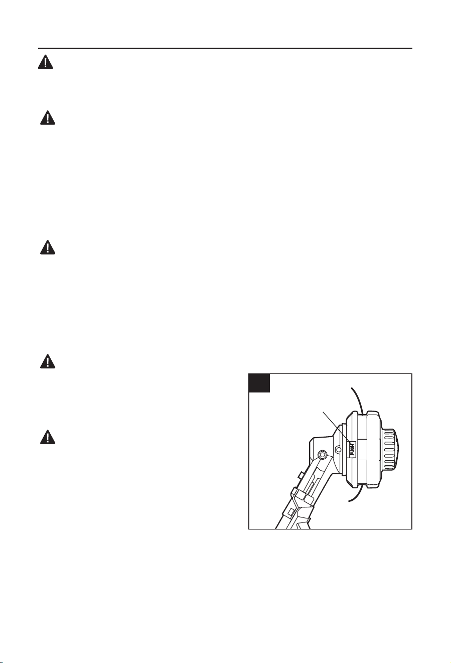
a. Press the two release tabs on the spool base
and remove the spool retainer by pulling it
straight out (Fig. 6a).
b. Use a clean cloth to clean the inner surface of the spool retainer and spool base.
NOTICE: Always clean the spool retainer and spool base before reassembling the trimmer head.
c. Check the spool retainer and spool base for worn or damaged parts.
6a
Tab
14
CARE AND MAINTENANCE
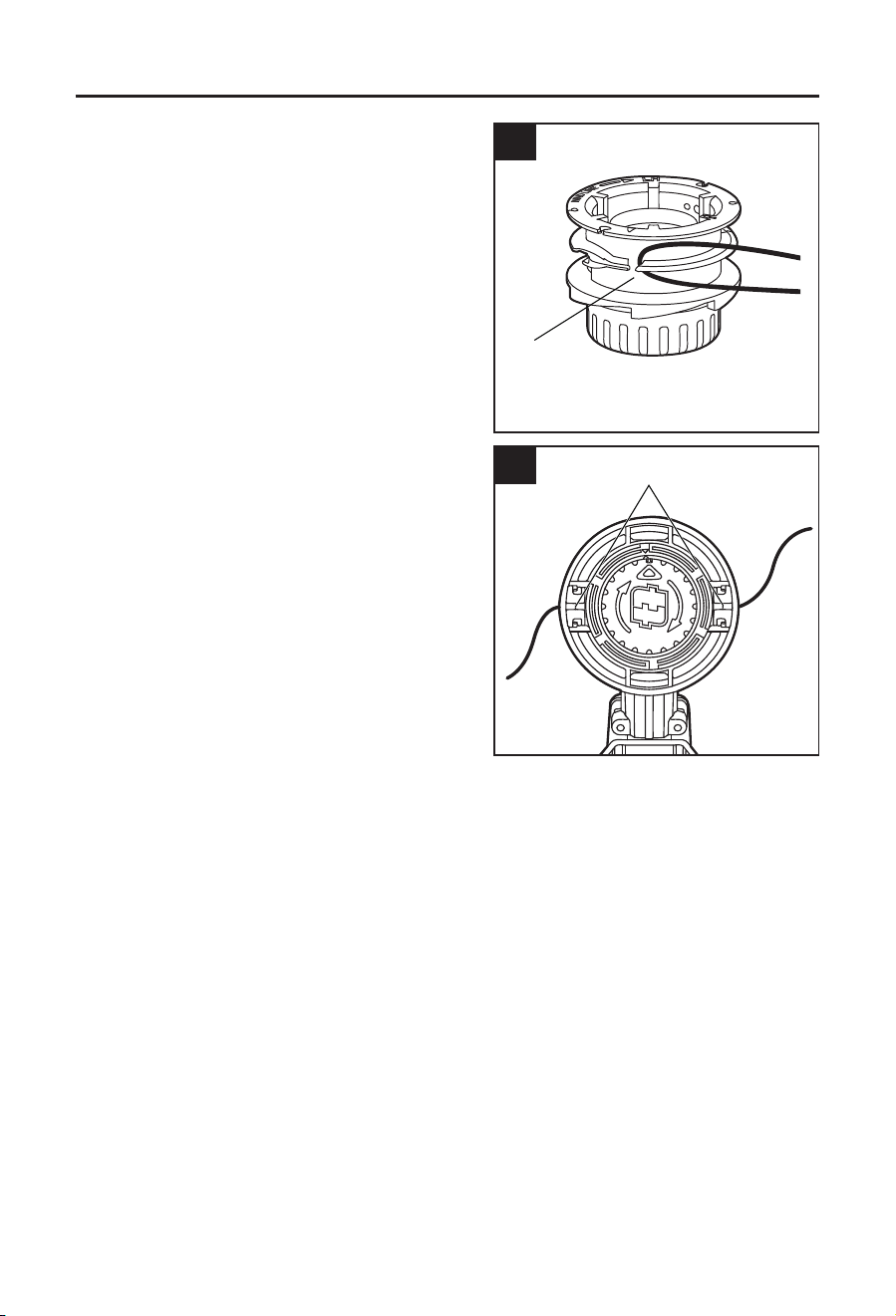
d. Fold the cutting line in half and hook the folded
end of the cutting line as shown in Fig. 6b.
e. Wind the line, in two even and tight layers,
onto the spool retainer.
NOTICE: Failure to wind the line in the direction
indicated will cause the trimmer head to operate
incorrectly.
f. Place the ends of the line in two opposite
eyelets (Fig. 6c).
g. Align the two tabs on the spool base with
the slots on trimmer head and press it until it
snaps into place (Fig. 6d).
NOTICE: Make sure that the tabs on the spool
base snap into place, otherwise the spool will
come out during operation.
6b
Spool
retainer
6c
Eyelets
15
CARE AND MAINTENANCE
You can replace the new line in another way:
WARNING
• To prevent serious personal injury, remove the
battery pack from the tool before servicing,
cleaning, changing attachments or removing
material from the unit.
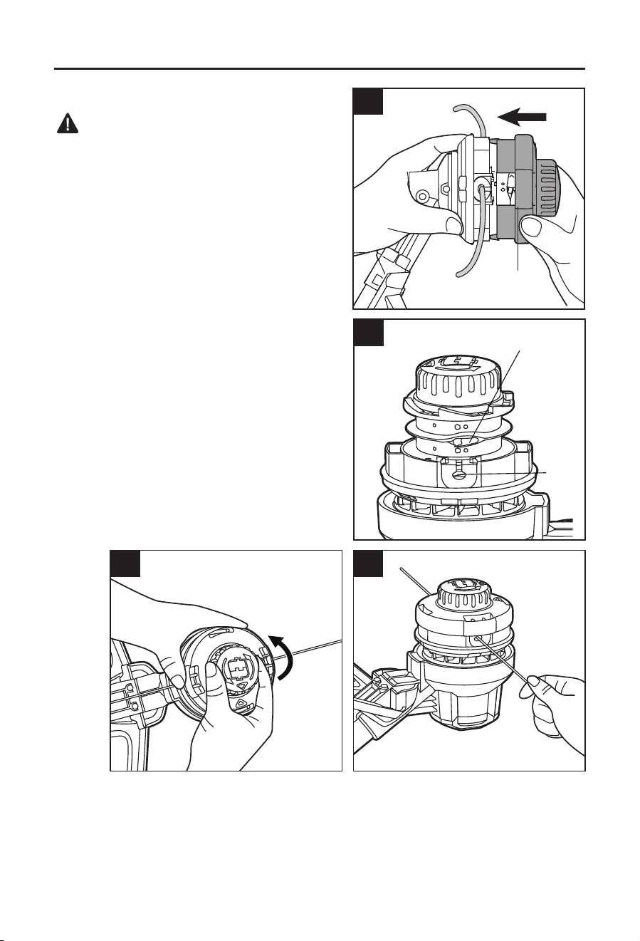
a. Press the two release tabs on the spool base
and remove the spool retainer.
b. Reinstall the spool retainer in such a way that
the threading hole on the spool retainer is
aligned with one of the eyelets (Fig. 6e).
c. Insert the new line into the eyelet. Feed the line
until the end of the line comes out of the other
side eyelet of the spool base (Fig. 6f).
d. Pull the line from the other side until equal
amounts of line appear on both sides.
e. Hold the spool base and rotate the bump head
in the direction indicated by the arrow to wind
the cutting line into the trimmer head (Fig. 6g).
• Push down on the bump head and check for
proper installation of the cutting line.
6e
Threading
hole
Eyelet
6f6g
6d
Spool base

16
CARE AND MAINTENANCE
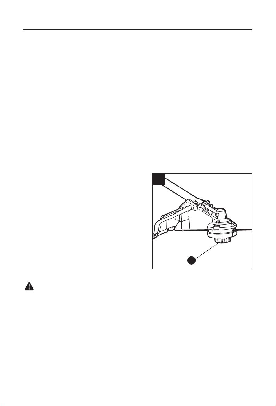
7. Transmission Gears Lubrication
The transmission gears in the gear case need be
lubricated periodically with gear grease. Check
the gear case grease level about every 50 hours
of operation by removing the sealing screw on the
side of the case.
If no grease can be seen on the sides of the gear,
follow the steps below to ll with gear grease up to
3/4 capacity.
Do not completely ll the transmission gear case.
a. Hold the string trimmer attachment on its side
so that the sealing screw is facing upwards
(Fig. 7).
b. Use the multi-function wrench (I) to loosen and remove the sealing screw.
c. Use a grease syringe (not included) to inject some grease into the lubrication opening,
taking care not to exceed 3/4 capacity.
d. Tighten the sealing screw after injection.
Storage
Clean the tool thoroughly before storing it.
Store the unit in a dry, well-ventilated area, locked-up or up high, out of the reach of children.
Keep away from corrosive agents, such as garden chemicals and de-icing salts.
7
Sealing screw
Gear case

17
TROUBLESHOOTING
WARNING:
• Release trigger switch (B) in the OFF position and remove the battery before performing
troubleshooting procedures.
PROBLEM POSSIBLE CAUSE CORRECTIVE ACTION
Tool does not
work.
1. Low battery pack capacity. 1. Charge the battery pack.
2. The battery pack is not
attached to the power head.
2. Attach the battery pack to the power
head.
String trimmer
stops while
cutting.
1. The motor shaft or trimmer
head is bound with grass.
1. Stop the trimmer, remove the battery
pack, and remove the grass from the
motor shaft and trimmer head.
2. The motor is overloaded. 2. Move the trimmer head to cut the
grass no more than 8 in. (20 cm) of
length in a single cut. Remove the
trimmer head from the grass and restart
the tool.
3. The battery pack or string
trimmer is too hot.
3. Release the trigger switch, wait for
the tool to cool down, and then start the
tool again.
4. The guard is not mounted
on the trimmer, resulting in
an overly long cutting line
and overload.
4. Remove the battery pack and mount
the guard on the trimmer.
Trimmer head
will not advance
the cutting line.
1. The trimmer head is bound
with grass.
1. Stop the trimmer, remove the battery
pack, and clean the trimmer head.
2. There is not enough line
on the spool.
2. Remove the battery pack and replace
the cutting line by following the section
“Line Replacement” in this manual.
WARRANTY
For 5 years from the date of purchase, this product is warranted for the original purchaser to
be free from defects in material and workmanship. This guarantee does not cover damage
due to abuse, normal wear, improper maintenance, neglect, unauthorized repair/alteration, or
expendable parts and accessories expected to become unusable after a reasonable period of
use. This warranty is limited to 90 days for commercial and rental use.
If you think your product meets the above guarantee criteria, please return it to the place of
purchase with valid proof of purchase and the defective product will be repaired or replaced at
no charge. This guarantee gives you specic legal rights, and you may also have other rights
that vary from state to state.
Lowe’s Home Centers LLC.
Mooresville, NC 28117
Printed in China

18
ARTÍCULO # 3809898/4132850/4665016 /5129684/5192325
ACCESORIO PARA
ORILLADORA
MODELO #KMS 1040-03
¿Preguntas, problemas, piezas faltantes? Antes de volver a la tienda, llame a nuestro
Departamento de Servicio al Cliente al 888-3KOBALT (888-356-2258), de lunes a domin-
go de 8 a.m. a 8 p.m., hora estándar del Este. También puede ponerse en contacto con
nosotros en [email protected].
ADJUNTE SU RECIBO AQUÍ
Número de serie Fecha de compra
KOBALT y el diseño del logotipo son marcas
comerciales o marcas registradas de LF, LLC.
Todos los derechos reservados.

20
ÍNDICE
Especicaciones del producto ........................................................................20
Contenido del paquete ................................................................................... 21
Información de seguridad ...............................................................................22
Preparación ....................................................................................................25
Instrucciones de funcionamiento ....................................................................28
Cuidado y mantenimiento ..............................................................................31
Solución de problemas ...................................................................................35
Garantía .........................................................................................................36
ESPECIFICACIONES DEL PRODUCTO
COMPONENTE ESPECIFICACIONES
Mecanismo de corte Cabezal de alimentación por golpeteo
Tipo de hilo de corte Hilo de nailon torcido de 0,08 pulgadas
Ancho de corte 33 cm (13 pulg.) / 38 cm (15 pulg.)
Temperatura de funcionamiento De 0° C (32 °F) a 40 °C (104 °F)
Temperatura de almacenaje De 0° C (32 °F) a 40 °C (104 °F)

21
CONTENIDO DEL PAQUETE
A
D
E
B
C
G
H
F
PIEZA DESCRIPCIÓN PIEZA DESCRIPCIÓN
A Cabezal de alimentación por
golpeteo
E
Cabezal de orilladoras
B Cuchilla del hilo de corte F Llave hexagonal
C Protector G Perno (2)
D Eje del accesorio para orilladora H Arandela de resorte (2)
ADVERTENCIA
• Retire la herramienta del paquete y examínela cuidadosamente. Inspeccione
cuidadosamente la herramienta para asegurarse de que no se produjo ninguna ruptura o
daño durante el envío. Si hay piezas faltantes o dañadas, devuelva este producto al lugar
donde lo compró. No deseche la caja ni ningún material de embalaje hasta después de
examinar todas las piezas.
• Si falta alguna pieza o si está dañada, no coloque la batería para usar la herramienta hasta
reparar o reemplazar dicha pieza. El incumplimiento de esta advertencia podría provocar
lesiones graves.

22
INFORMACIÓN DE SEGURIDAD
Lea y comprenda completamente este manual antes de intentar ensamblar u operar este
producto. Si tiene preguntas relacionadas con el producto, llame al Departamento de Servicio
al Cliente al 888-3KOBALT (888-356-2258), de lunes a domingo de 8 a.m. a 8:00 p.m., hora
estándar del Este. También puede ponerse en contacto con nosotros a través de partsplus@
lowes.com.
ADVERTENCIA
• Operar cualquier herramienta eléctrica puede provocar que objetos extraños salten a sus
ojos y que, consecuentemente, le causen graves daños oculares. Use siempre lentes o
gafas de seguridad con protecciones laterales y, cuando sea necesario, una mascarilla que
cubra todo el rostro antes de comenzar a operar una herramienta eléctrica. Recomendamos
usar una máscara de seguridad de visión amplia sobre los lentes o gafas de seguridad con
protecciones estándar. Siempre use lentes de protección que cumplan con la norma ANSI
Z87.1.
• Parte del polvo producido por el lijado, el serruchado, la trituración y el taladrado eléctrico
y otras actividades de construcción contiene productos químicos reconocidos por el estado
de California como causantes de cáncer, defectos congénitos u otros daños en el aparato
reproductivo. Algunos ejemplos de estos productos químicos son los siguientes:
– Plomo de pinturas a base de plomo
– Sílice cristalina de ladrillos, cemento y otros productos de mampostería
– Arsénico y cromo de madera tratada con químicos
• El riesgo que corre debido a la exposición varía según la frecuencia con la que realiza este
tipo de trabajo. Para reducir la exposición a estos productos químicos:
– Trabaje en un área bien ventilada.
– Trabaje con equipo de seguridad aprobado, como las mascarillas antipolvo
especialmente diseñadas para ltrar partículas microscópicas.
– Evite estar en contacto prolongado con el polvo provocado por el lijado, el serruchado,
la trituración, el taladrado y otras actividades de construcción. Use ropa protectora y lave
todas las áreas expuestas del cuerpo con agua y jabón. Si el polvo ingresa a la boca o a
los ojos, o si cae sobre la piel, es posible que se absorban productos químicos dañinos.
Conozca la herramienta
Para operar esta herramienta, lea cuidadosamente este manual y todas las etiquetas jadas a
la herramienta antes de usarla. Guarde este manual para referencia futura.
Importante
Solo un técnico calicado puede reparar esta herramienta.
Lea por completo todas las instrucciones
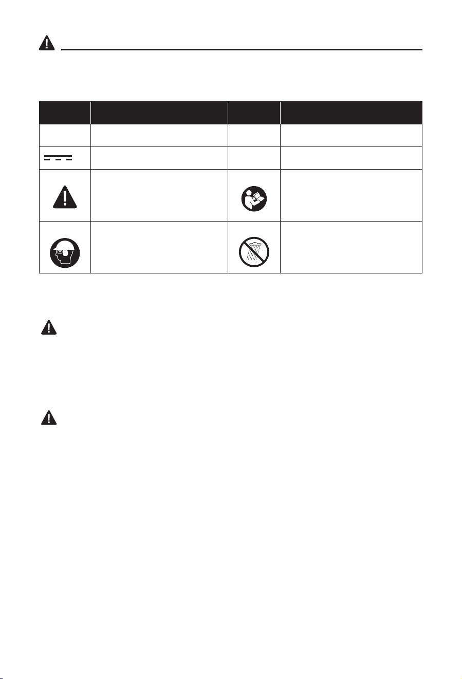
23
INFORMACIÓN DE SEGURIDAD
Algunos de los siguientes símbolos pueden aplicarse al uso de esta herramienta. Obsérvelos
y aprenda su signicado. La interpretación correcta de estos símbolos le permitirá utilizar la
herramienta de manera ecaz y segura.
SÍMBOLO DEFINICIÓN SÍMBOLO DEFINICIÓN
V Voltios n
0
Velocidad sin carga
Corriente directa RPM Revoluciones por minuto
Peligro, advertencia o
precaución. Signica
"¡Atención! Su seguridad está
comprometida".
Para reducir el riesgo de
lesiones, el usuario debe leer el
manual de instrucciones.
Wear eye, ear and head
protection.
No lo exponga a la lluvia.
INSTRUCCIONES IMPORTANTES DE SEGURIDAD
ADVERTENCIA
• Cuando utilice orilladoras eléctricas, siga siempre las medidas de seguridad básicas para
reducir el riesgo de incendios, descargas eléctricas y lesiones personales, incluido lo
siguiente:
LEA TODAS LAS INSTRUCCIONES
PELIGRO
• No confíe exclusivamente en el aislamiento de la herramienta contra las descargas
eléctricas. Para reducir el riesgo de descarga eléctrica, no utilice la herramienta cerca
de conductores o cables que puedan transportar corriente eléctrica.
Advertencias de seguridad para la bordeadora de césped
• No utilice la máquina en condiciones meteorológicas adversas, especialmente
cuando haya riesgo de rayos. Esto disminuirá el riesgo de que le caiga un rayo.
• Inspeccione minuciosamente la zona en la que se va a utilizar la máquina en
busca de animales. La fauna silvestre puede resultar herida por la máquina durante su
funcionamiento.
• Inspeccione minuciosamente el área donde se utilizará la herramienta y retire las
piedras, ramas, cables, huesos y cualquier otro objeto extraño que encuentre. Los
objetos arrojados pueden causar lesiones personales.
• Antes de usar la máquina, siempre inspeccione visualmente para comprobar que
el cortador o la cuchilla, así como el ensamble del cortador o la cuchilla no estén
dañados. Las piezas dañadas aumentan el riesgo de lesiones.

24
INFORMACIÓN DE SEGURIDAD
• Siga las instrucciones para cambiar los accesorios. Si las tuercas o los pernos de
jación de la cuchilla no están bien apretados, pueden dañar la cuchilla o hacer que se
desprenda.
• Utilice protección para los ojos, los oídos, la cabeza y las manos. Un equipo de
protección adecuado reducirá las lesiones personales causadas por los desechos que
salgan despedidos o por el contacto accidental con la línea de corte o la cuchilla.
• Durante el uso de la máquina, lleve siempre calzado antideslizante y de protección.
No utilice la máquina si está descalzo o lleva sandalias abiertas. Esto reduce la
posibilidad de que los pies se lesionen al entrar en contacto con las cuchillas o los
conductos en movimiento.
• Durante el funcionamiento de la máquina, use siempre pantalones largos. La piel
expuesta aumenta la probabilidad de lesiones causadas por objetos arrojados.
• Mantenga alejados a los transeúntes mientras se utiliza la máquina. Los desechos
arrojados pueden provocar lesiones personales graves.
• Utilice siempre las dos manos para manejar la máquina. Sujetar la máquina con ambas
manos evitará la pérdida de control.
• Sujete la máquina únicamente por las supercies de agarre aisladas, ya que la línea
de corte o la cuchilla pueden entrar en contacto con cables ocultos. El contacto de
la línea de corte o de las cuchillas con un cable con corriente puede hacer que las piezas
metálicas expuestas de la máquina queden energizadas y podrían provocar una descarga
eléctrica al operador.
• Mantenga siempre una posición correcta y utilice la máquina solo cuando esté de
pie en el suelo. Las supercies resbaladizas o inestables pueden provocar una pérdida de
equilibrio o de control de la máquina.
• No utilice la máquina en pendientes excesivamente pronunciadas. Esto aumenta
el riesgo de pérdida de control, resbalones y caídas que pueden provocar lesiones
personales.
• Cuando trabaje en pendientes, asegúrese siempre de pisar bien, trabaje siempre en
sentido transversal, nunca hacia arriba o hacia abajo, y extreme las precauciones al
cambiar de dirección. Esto reduce el riesgo de pérdida de control, resbalones y caídas
que pueden provocar lesiones personales.
• Mantenga todas las partes del cuerpo alejadas del cortador, la línea o la cuchilla
cuando la máquina esté en funcionamiento. Antes de poner en marcha la máquina,
asegúrese de que el cortador, la línea o la cuchilla no estén en contacto con nada.
Un momento de falta de atención mientras se opera la máquina puede provocar lesiones a
usted o a otras personas.
• No utilice la máquina por encima de la altura de la cintura. Esto ayuda a evitar el
contacto involuntario con la cuchilla o el cortador, y permite un mejor control de la máquina
en situaciones inesperadas.
• Al cortar arbustos o árboles jóvenes que estén bajo tensión, esté atento a los
retrocesos bruscos. Cuando se libera la tensión de las bras de la madera, la maleza o
los árboles jóvenes, es posible que las ramas golpeen al operador o hagan perder el control
de la máquina.
• Tenga mucho cuidado al cortar arbustos y árboles jóvenes. El material delgado puede
atrapar la cuchilla y azotarse hacia usted o hacerle perder el equilibrio.
• Mantenga el control de la máquina y no toque los cortadores, las líneas o las
cuchillas, ni otras piezas móviles peligrosas mientras estén en movimiento. Esto
reduce el riesgo de lesiones por las piezas móviles.
• Transporte la máquina estando apagada y lejos de su cuerpo. Un manejo adecuado
de la máquina reducirá la probabilidad de un contacto accidental con un cortador, línea o
cuchilla en movimiento.

25
INFORMACIÓN DE SEGURIDAD
• Utilice únicamente cortadores, líneas, cabezales de corte y cuchillas de repuesto
especicados por el fabricante. Las piezas de repuesto incorrectas pueden aumentar el
riesgo de rotura y lesiones.
• Cuando limpie el material atascado o realice el mantenimiento de la máquina,
asegúrese de que el interruptor está apagado y que se haya retirado el paquete de
baterías. La puesta en marcha inesperada de la máquina mientras se limpia el material
atascado o se realiza el mantenimiento puede provocar lesiones personales graves.
• Úselo solo con el cabezal de potencia de 40 V KMH 1040-03 o el cabezal de potencia
de 24 V KMH 1024-03.
NOTA: consulte el manual del operador del cabezal de potencia KOBALT (KMH 1040-03 y
KMH 1024-03) para conocer las reglas de seguridad especícas.
GUARDE ESTAS INSTRUCCIONES
PREPARACIÓN
Conozca su orilladora
Este producto requiere ensamblaje. Extraiga la herramienta de la caja cuidadosamente y
colóquela sobre una supercie de trabajo nivelada. Antes de intentar usar el accesorio para
orilladora, familiarícese con todas sus características de operación y requisitos de seguridad.
ADVERTENCIA
• Sea cuidadoso, incluso si está familiarizado con la herramienta. Recuerde que un momento
de descuido es suciente para causar lesiones graves. Antes de intentar utilizar cualquier
herramienta, asegúrese de familiarizarse con todas las características de funcionamiento e
instrucciones de seguridad.
• No intente modicar esta herramienta ni crear accesorios que no sean los recomendados
para esta. Cualquier alteración o modicación se considera un uso inadecuado y podría
causar una condición peligrosa que produzca lesiones personales graves.
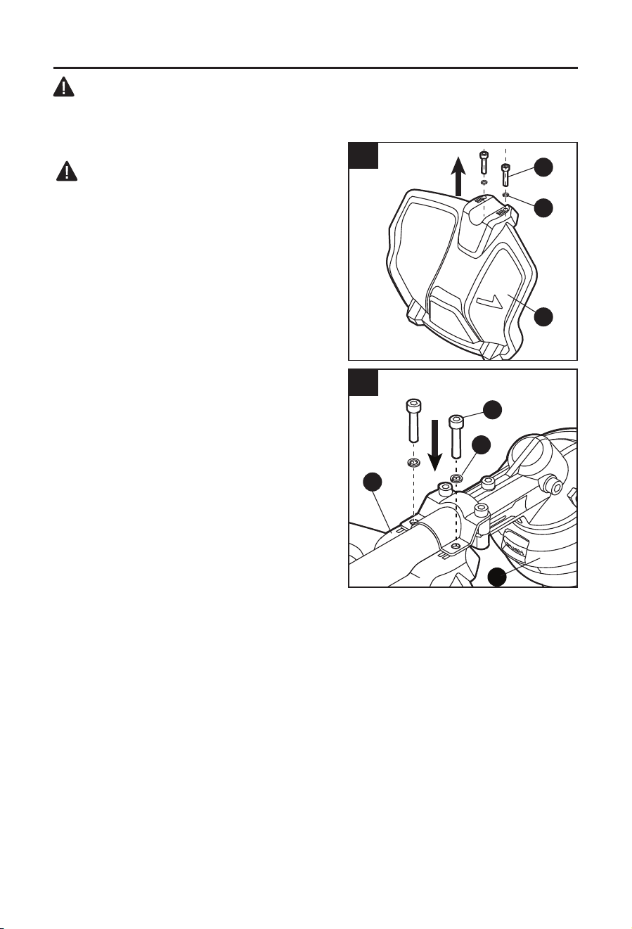
26
INSTRUCCIONES DE ENSAMBLAJE
ADVERTENCIA: este producto requiere ensamblaje. Para reducir el riesgo de lesiones a
personas, no use la herramienta si el protector no está en su lugar. El protector siempre debe
estar en la herramienta para proteger al usuario.
1. Montaje del protector
ADVERTENCIA
• Instale el protector antes de conectar el accesorio
al cabezal de potencia.
• Para reducir el riesgo de lesiones a personas, no
opere sin el protector en su lugar.
a. Aoje los dos pernos (G) del protector con la
llave hexagonal provista (F). Retire los pernos
y las arandelas de resorte (H) del protector (C)
(Fig. 1a).
b. Levante el cabezal de la orilladora (E) y
oriéntelo hacia abajo; alinee los dos oricios de
montaje del protector con los dos oricios de
ensamble de la base del eje. Asegúrese de que
la cara interna del protector se oriente hacia el
cabezal de la orilladora (Fig. 1b).
c. Utilice la llave hexagonal provista para
asegurar el protector en su lugar con las
arandelas y los pernos.
1a
H
C
G
G
H
E
C
1b

27
INSTRUCCIONES DE ENSAMBLAJE
2. Conexión del accesorio para orilladora al
cabezal de potencia (KMH 1040-03 y
KMH 1024-03)
Instalación del accesorio
a. Retire el paquete de baterías del cabezal de
potencia.
b. Aoje la perilla mariposa del eje del cabezal de
potencia (Fig. 2a).
c. El cabezal de potencia tiene dos ranuras en
el acoplador; SOLO la ranura 1 se usa para
conectar este accesorio.
ADVERTENCIA
• No instale este accesorio con la ranura 2 porque
puede causar lesiones personales durante la
operación.
d. Alinee el pasador activado por resorte del
accesorio con la ranura del acoplador y empuje
el eje del accesorio en el eje del cabezal de
potencia hasta que el pasador salga de la
ranura y escuche un sonido de “clic” al mismo
tiempo (Fig. 2b).
e. Jale el eje del accesorio para vericar que esté
rmemente asegurado en el acoplador.
f. Ajuste rmemente la perilla mariposa.
Extracción del accesorio
a. Retire el paquete de baterías del cabezal de
potencia.
b. Aoje la perilla mariposa.
c. Presione hacia abajo el pasador activado por resorte y extraiga el eje del accesorio del
acoplador (Fig. 2c).
2b
Ranura
Pasador
Eje del
accesorio
2c
Eje del
accesorio
Pasador
2a
Eje del cabezal de potencia
Ranura 2
Perilla mariposa
Ranura 1
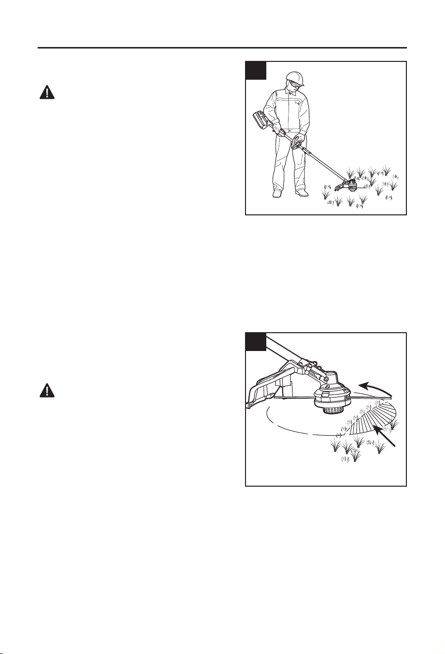
28
INSTRUCCIONES DE FUNCIONAMIENTO
3. Cómo sostener la orilladora
ADVERTENCIA
• Use ropa adecuada para reducir el riesgo de
lesiones cuando opere esta herramienta.
No use ropa holgada ni joyas. Use protección
para los ojos y las orejas. Use pantalones largos
y pesados, botas y guantes. No use pantalones
cortos ni sandalias, ni tenga los pies descalzos.
Antes de usar la unidad, colóquese en la posición
de operación y verique lo siguiente:
• El operador usa lentes de protección y ropa
adecuada.
• Un brazo está ligeramente doblado. La mano de ese brazo sostiene la manija trasera.
• El otro brazo está recto. La mano de ese brazo sostiene la manija delantera.
• El cabezal de la orilladora se encuentra paralelo al suelo y entra en contacto fácilmente con
el material que debe cortar, sin que el operador deba inclinarse.
4. Encendido y apagado de la orilladora
Consulte la sección “CÓMO ENCENDER/DETENER EL CABEZAL DE POTENCIA” en el
manual del operador del cabezal de potencia KMH 1040-03.
5. Uso de la orilladora
Consejos para obtener mejores resultados de
corte (Fig. 5a)
ADVERTENCIA
• Revise si hay piezas dañadas o desgastadas
antes de cada uso.
• Para evitar lesiones personales graves, use
gafas o lentes de seguridad en todo momento
al trabajar con esta unidad. Use una máscara
o mascarilla antipolvo en lugares donde hay
polvo. Use ropa y calzado adecuados durante
el uso para reducir el riesgo de lesiones que
pueden originarse a causa de desechos
eyectados.
• Despeje el área que va a cortar antes de cada uso. Retire todos los objetos, como rocas,
vidrios rotos, clavos, alambres o cuerdas, que puedan ser lanzados por la máquina o
que puedan enredarse en el accesorio de corte. Despeje el área de niños, transeúntes y
mascotas. Como mínimo, mantenga a todos los niños, transeúntes y mascotas al menos a
30,5 m (100 pies) de distancia. Aún podrían existir riesgos para los transeúntes debido a los
objetos disparados.
• Se debe pedir a los transeúntes que usen lentes de protección. Si alguien se aproxima a
usted, detenga el motor y el accesorio de corte inmediatamente.
• El ángulo correcto del accesorio de corte es paralelo al suelo.
3
5a
Dirección de
la rotación
Área de
corte ideal
Área de corte
peligrosa
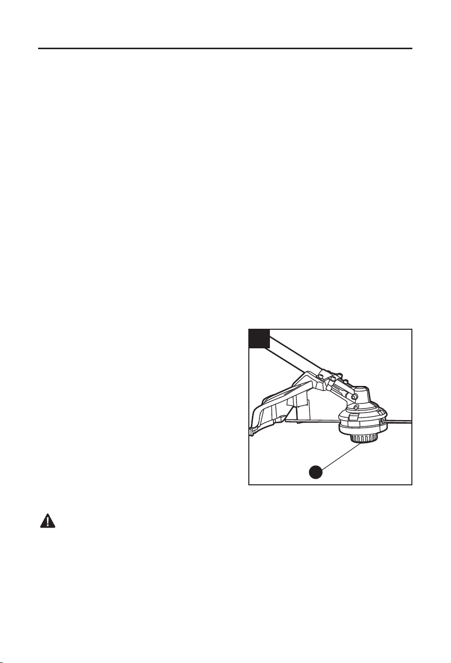
29
INSTRUCCIONES DE FUNCIONAMIENTO
• Esta orilladora le permite apoyar el cabezal de alimentación por golpeteo (A) sobre el suelo
para un funcionamiento más cómodo.
• No fuerce la herramienta. Permita que la punta del hilo realice el corte (especialmente
contra las paredes). Si corta con más que la punta, se reducirá la eciencia de corte y se
provocará una sobrecarga del motor.
• La altura de corte se determina según la distancia del hilo de corte a la supercie del
césped.
• El césped de más de 200 mm (8 pulg.) debe cortarse desde la parte superior hacia la
inferior en pequeños incrementos para evitar el desgaste prematuro del hilo o el arrastre del
motor.
• Mueva lentamente la orilladora de hilo dentro y fuera del área que cortará y mantenga
la posición del cabezal de corte en la altura de corte que desea. Este puede ser un
movimiento hacia delante y hacia atrás, o de un lado a otro. El corte de largos menores
produce mejores resultados.
• Corte el césped y las malezas solo cuando estén secos.
• Las cercas de alambre y de estacas pueden causar un desgaste excesivo o roturas.
Las paredes de piedra o ladrillo, los bordes y la madera puede desgastar las cuerdas
rápidamente.
• Evite los árboles y arbustos. Las cuerdas pueden dañar fácilmente las cortezas de los
árboles, las molduras en madera, los paneles de revestimiento y los postes para cerca.
Ajuste del largo del hilo de corte (Fig. 5b)
El cabezal de la orilladora le permite al operador
liberar más hilo de corte sin detener el motor.
A medida que el hilo se rasga o desgasta, puede
liberarse hilo adicional si se golpea ligeramente el
cabezal de alimentación por golpeteo (A) contra el
suelo mientras se usa la orilladora (Fig. 5b).
Para obtener mejores resultados, golpee el cabezal
de alimentación por golpeteo contra suelo desnudo
o tierra dura. Si intenta liberar hilo en césped alto,
el motor puede sobrecalentarse.
Siempre mantenga el hilo de la orilladora
completamente extendido. La liberación de hilo se
hace más difícil a medida que el hilo de corte se acorta.
ADVERTENCIA
• No retire ni modique el ensamble de la cuchilla del hilo de corte. Un largo excesivo del hilo
puede producir el sobrecalentamiento del motor y esto puede dar como resultado lesiones
personales graves.
5b
A
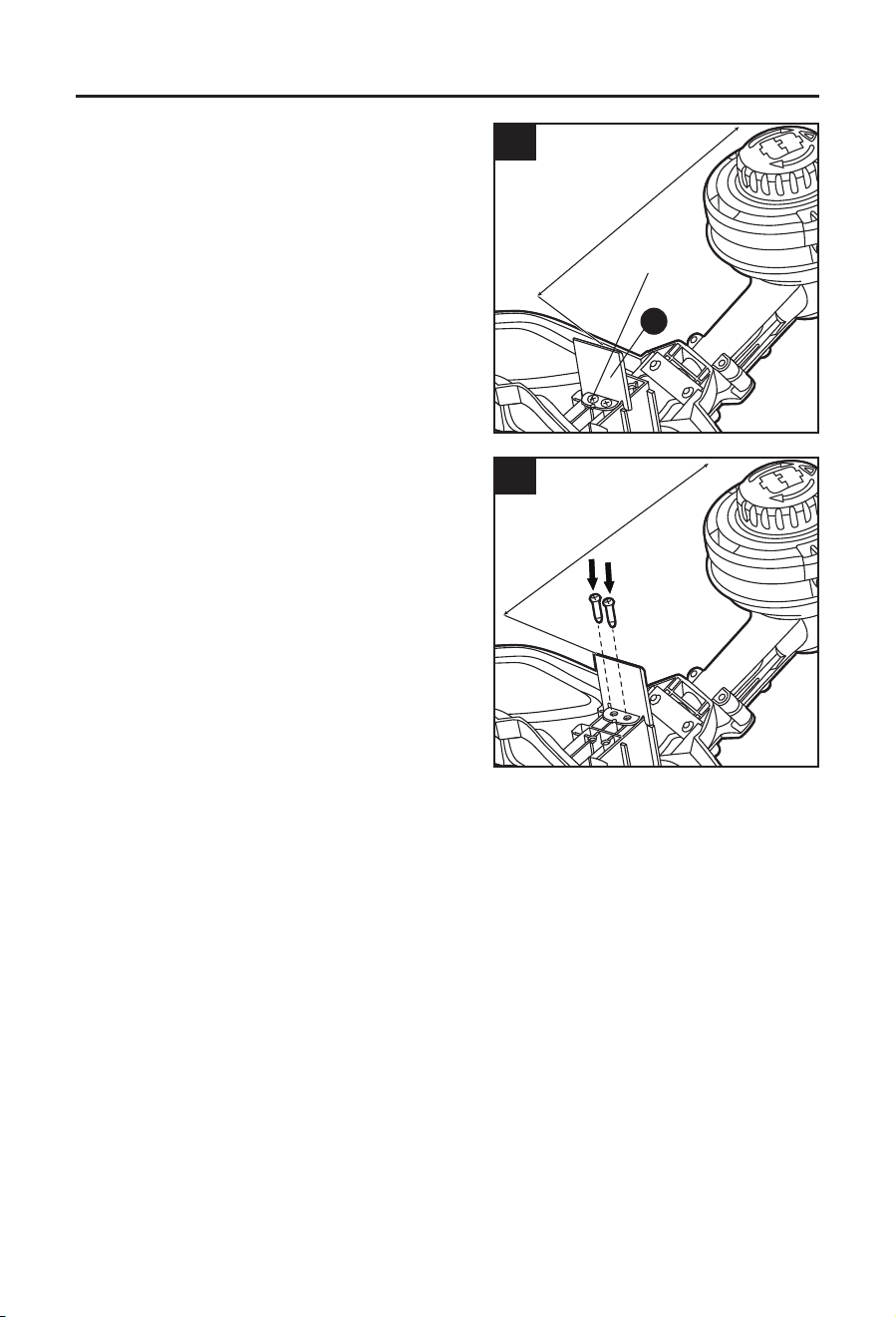
30
INSTRUCCIONES DE FUNCIONAMIENTO
Ajuste de la amplitud de corte
La orilladora viene ajustada de fábrica a una
amplitud de corte de 38,1 cm (15 pulg.). Para
reducir la hilera de corte de 38,1 cm a 33,02 cm
(15 pulg. a 13 pulg.):
a. Retire el paquete de baterías de la
herramienta.
b. Utilice un destornillador Phillips (no se incluye)
para aojar y retirar los dos tornillos que jan la
cuchilla para corte de hilo (B) al protector
(Fig. 5c).
c. Mueva la cuchilla y alinee los dos oricios de la
cuchilla con los otros dos oricios del protector
(Fig. 5d).
d. Inserte los dos tornillos y apriételos bien.
5d
33,01cm (13 pulg.)
5c
Tornillos
38,1 cm (15 pulg.)
B
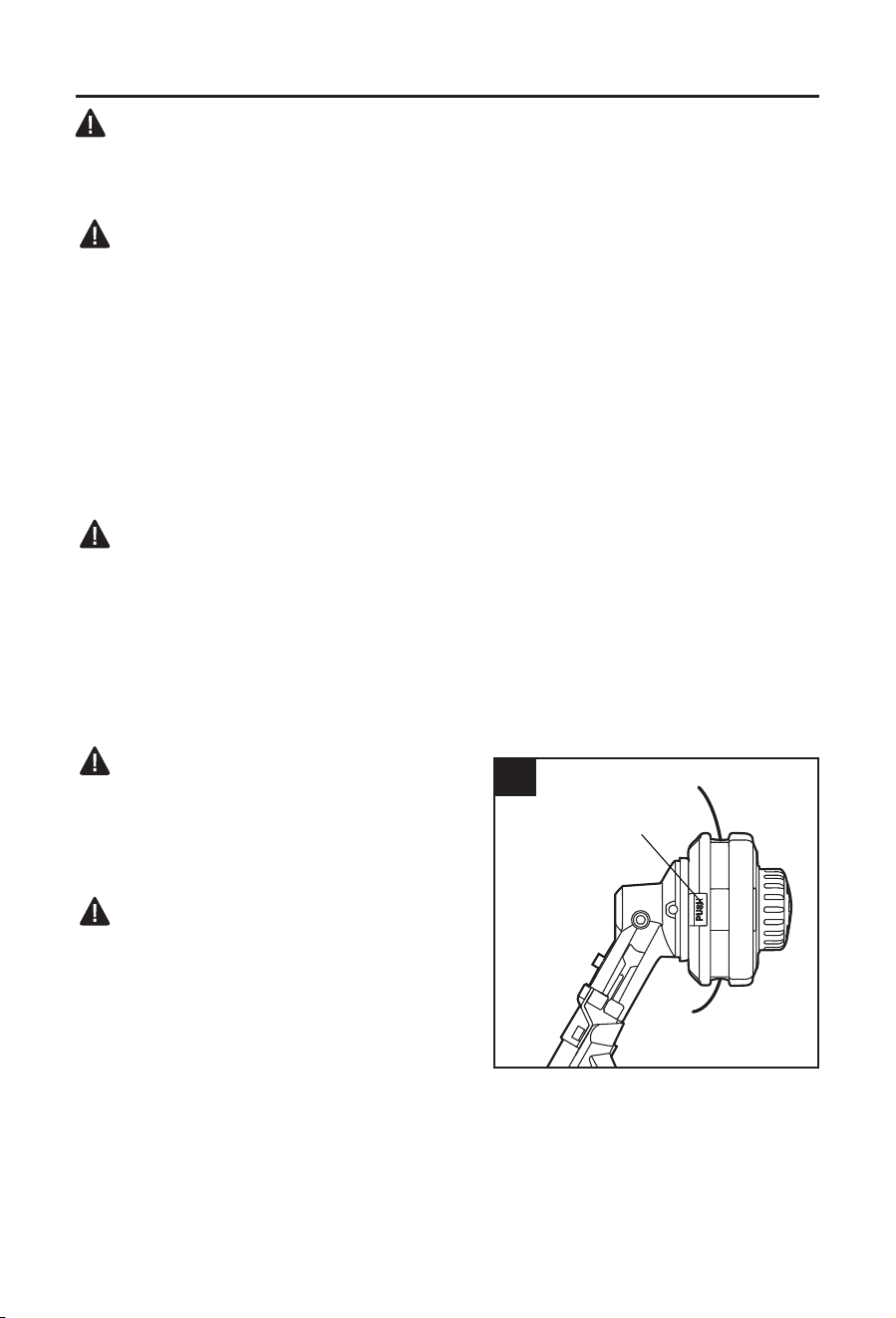
31
CUIDADO Y MANTENIMIENTO
ADVERTENCIA
Todo el mantenimiento debe estar a cargo solo de un técnico de servicio calicado.
Limpie la orilladora después de cada uso.
ADVERTENCIA
• Para evitar lesiones personales graves, retire el paquete de baterías de la herramienta
antes de realizar el mantenimiento, limpiarlo, cambiar los accesorios o retirar el material de
la herramienta.
a. Limpie el pasto que pueda cubrir el eje del motor o el cabezal de la orilladora.
b. Use solo un paño limpio, seco y suave para limpiar la herramienta. Nunca deje que
ingresen líquidos a la herramienta; nunca sumerja alguna pieza de la herramienta en
líquido.
c. Mantenga los conductos de ventilación libres de desechos en todo momento.
AVISO: la obstrucción de los conductos de ventilación impide que el aire uya al armazón del
motor, lo cual puede producir el sobrecalentamiento o el daño del motor.
ADVERTENCIA
• Nunca utilice agua para limpiar la orilladora. Evite utilizar solventes para limpiar las piezas
de plástico. La mayoría de los plásticos son susceptibles a diferentes tipos de solventes
comerciales. Utilice paños limpios para eliminar la suciedad, el polvo, el aceite, la grasa, etc.
6. Reemplazo del hilo
AVISO: siempre use hilo de corte de nailon torcido triangular de un tamaño que no supere
los 2 mm (0,08 pulg.). El uso de hilos diferentes de los especicados puede ocasionar que la
orilladora se sobrecaliente o se dañe.
ADVERTENCIA
• Nunca use hilo de metal reforzado, alambre
o cuerda, etc. Estos podrían romperse y
convertirse en un proyectil peligroso.
Enrollado del carrete con el hilo nuevo
ADVERTENCIA
• Para evitar lesiones personales graves, retire el
paquete de baterías de la herramienta antes de
realizar el mantenimiento, limpiarlo, cambiar los
accesorios o retirar el material de la unidad.
a. Presione las dos lengüetas de liberación de
la base del carrete y retire el retenedor del
carrete jalándolo hacia afuera (Fig. 6a).
b. Use un paño limpio para limpiar la supercie interna del retenedor del carrete y la base del
carrete.
AVISO: siempre limpie el retenedor del carrete y la base del carrete antes de volver a ensamblar
el cabezal de la orilladora.
c. Verique si hay piezas desgastadas o dañadas en el retenedor del carrete o la base del
carrete.
6a
Lengüeta

32
CUIDADO Y MANTENIMIENTO
d. Doble el hilo de corte por la mitad y enganche
el extremo plegado del hilo de corte, como, se
muestra en la Fig. 6b.
e. Enrolle el hilo en dos capas uniformes y
apretadas sobre el retenedor del carrete.
AVISO: si no se enrolla el hilo en la dirección que
se indica, el cabezal de la orilladora funcionará
incorrectamente.
f. Coloque los extremos del hilo en dos ojales
opuestos (Fig. 6c).
g. Alinee las dos lengüetas de la base del carrete
con las ranuras del cabezal de la orilladora
y presiónelas hasta que encajen en su lugar
(Fig. 6d).
AVISO: asegúrese de que las lengüetas de
la base del carrete se jen en su lugar o, de
lo contrario, el carrete se saldrá durante el
funcionamiento.
6b
Retenedor
del carrete
6c
Ojales

33
CUIDADO Y MANTENIMIENTO
Puede reemplazar el hilo nuevo de otra manera:
ADVERTENCIA
• Para evitar lesiones personales graves, retire el
paquete de baterías de la herramienta antes de
realizar el mantenimiento, limpiarlo, cambiar los
accesorios o retirar el material de la unidad.
a. Presione las dos lengüetas de liberación de
la base del carrete y retire el retenedor del
carrete.
b. Vuelva a instalar el retenedor del carrete de
tal manera que el oricio de enhebrado del
retenedor del carrete quede alineado con uno
de los ojales (Fig. 6e).
c. Coloque el hilo nuevo en el ojal. Inserte el hilo
hasta que el extremo nal salga por el otro ojal
lateral de la base del carrete (Fig. 6f).
d. Tire del hilo desde el otro lado hasta que
aparezcan cantidades iguales de hilo en ambos
lados.
e. Sostenga la base del carrete y gire el cabezal
de alimentación por golpeteo en la dirección
indicada por la echa a n de enrollar el hilo de
corte en el cabezal de la orilladora (Fig. 6g).
• Empuje el cabezal de alimentación por golpeteo
hacia abajo y verique que el hilo de corte esté
instalado correctamente.
6e
Oricio de
roscado
Ojal
6f6g
6d
Base del
carrete
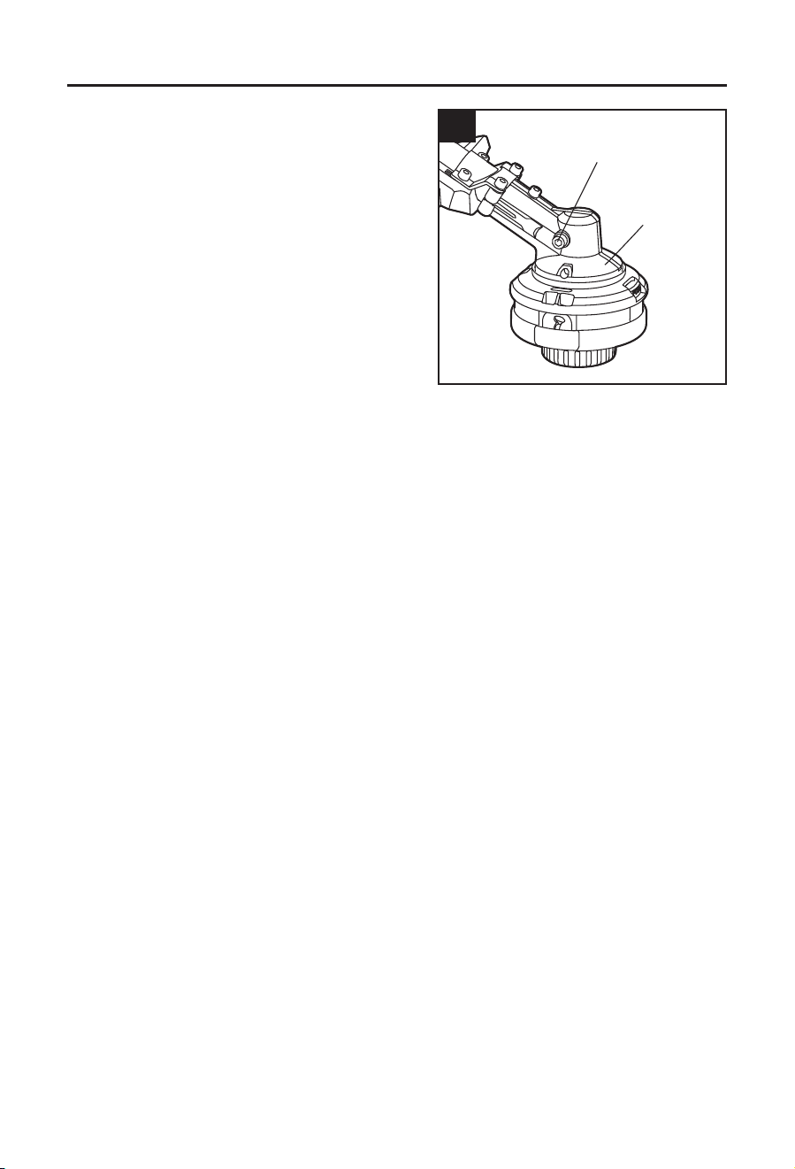
34
CUIDADO Y MANTENIMIENTO
7. Lubricación de los cambios de transmisión
Los cambios de transmisión en la caja de cambios
tienen que lubricarse periódicamente con aceite
para cambios. Verique el nivel de grasa de la caja
de cambios aproximadamente cada 50 horas de
funcionamiento al retirar el tornillo sellador en el
lateral de la caja.
Si no se ve grasa en los laterales del cambio,
siga los pasos a continuación para engrasar los
cambios hasta ¾ de la capacidad.
No llene por completo la caja de cambios de
transmisión.
a. Sostenga el accesorio para orilladora de
costado de modo que el tornillo sellador quede hacia arriba (Fig. 7).
b. Utilice la llave multiuso (I) para aojar y retirar el tornillo sellador.
c. Utilice una jeringa de grasa (no se incluye) para inyectar algo de grasa en el oricio de
lubricación sin superar los 3/4 de la capacidad.
d. Apriete el tornillo sellador luego de la inyección.
Almacenamiento
Haga una limpieza profunda de la herramienta antes de almacenarla.
Almacene la unidad en un lugar seco y bien ventilado, alto o con seguro y fuera del alcance
de los niños. Debe mantenerse alejada de agentes corrosivos, como productos químicos para
jardín y sales descongelantes.
7
Tornillo de sellado
Caja de cambios

35
SOLUCIÓN DE PROBLEMAS
ADVERTENCIA:
• Suelte el interruptor tipo gatillo (B) en la posición de APAGADO y retire el paquete de baterías
antes de realizar los procedimientos de solución de problemas.
PROBLEMA CAUSA POSIBLE ACCIÓN CORRECTIVA
La herramienta
no funciona.
1. La capacidad del paquete
de baterías es baja.
1. Cargue el paquete de baterías.
2. El paquete de baterías
no está jo al cabezal de
potencia.
2. Fije el paquete de baterías al cabezal
de potencia.
La orilladora se
detiene mientras
se corta.
1. El eje del motor o el
cabezal de la orilladora
están atascados con
césped.
1. Detenga la orilladora, retire el paquete
de baterías y quite el césped del
eje del motor y del cabezal de la
orilladora.
2. El motor está
sobrecargado.
2. Mueva el cabezal de la orilladora para
cortar el césped no más de 20 cm
(8 pulg.) de largo en un solo corte.
Retire el cabezal de la orilladora del
césped y reinicie la herramienta.
3. El paquete de baterías o
la orilladora est demasiado
caliente.
3. Suelte el interruptor tipo gatillo,
espere que la herramienta se enfríe y
luego vuelva a encenderla.
4. El protector no está
instalado en la orilladora,
lo que genera una línea de
corte demasiado larga y
una sobrecarga.
4. Retire el paquete de baterías e instale
el protector en la orilladora.
El cabezal de
la orilladora no
hace avanzar el
hilo de corte.
1. El cabezal de la orilladora
está atascado con césped.
1. Detenga la orilladora, retire el paquete
de baterías y limpie el cabezal de la
orilladora.
2. No hay suciente hilo en el
carrete.
2. Retire el paquete de baterías y
reemplace el hilo de corte. Para ello,
siga la sección "Reemplazo del hilo"
de este manual.

36
GARANTÍA
Este producto tiene cobertura de garantía contra defectos en materiales y mano de obra
durante 5 años a partir de la fecha de compra para el comprador original. Esta garantía no
cubre daños debidos al maltrato, desgaste normal, mantenimiento inadecuado, negligencia,
reparaciones o alteraciones no autorizadas, o piezas y accesorios prescindibles que se espera
que resulten inutilizables después de un período de uso razonable. Esta garantía está limitada
a 90 días para uso comercial y de alquiler.
Si cree que este producto cumple con la garantía mencionada anteriormente, devuelva
el producto al lugar donde lo compró con un comprobante de compra válido y el producto
defectuoso se reparará o reemplazará sin cargo. Esta garantía le otorga derechos legales
especícos, pero también podría tener otros derechos que varían según el estado.
Lowe’s Home Centers LLC.
Mooresville, NC 28117
Impreso en China
