
ITEM #4134949/ #4115489/ #4115490
MODEL #TPGAZ2303D/ #TPGAZ2403A/ #TPGAZ2403C
1
AS21330
Espanol p. 15
ATTACH YOUR RECEIPT HERE
Serial Number
___________
Purchase Date
___________
Questions, problems, missing parts? Before returning to your retailer, call our customer
ervice department at 1-866-439-9800, 8 a.m. - 8 p.m., EST, Monday - Sunday.
You could also contact us at partsplus@lowes.com or visit www.lowespartsplus.com.
ALLEN + ROTH and logo design are trademarks
or registered trademarks of LF, LLC.
All Rights Reserved.
2
TABLE OF CONTENTS
DESCRIPTION
3
D
Q
E
F
G
H
N
O
P
A
C
B
S
R
M
T
U
V
L
K
I
J
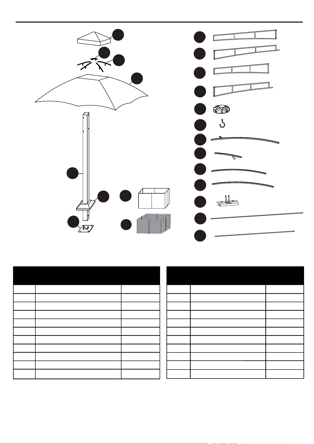
PACKAGE CONTENTS
PART PART
Supporting Post
Post Bottom Plate
Post Plate Cover
Long Left Crossbar
Long Right Crossbar
Short Left Crossbar
Short Right Crossbar
Roof Connector
Hook
Long Top Connector Pole
Small Connector Pole
A
B
C
D
E
F
G
H
I
J
K
4
4
4
2
2
2
2
1
1
4
4
Short Top Pole
Short Top Pole
Small Top Connector
Small Top Beam
Air Vent Cover
Fabric Cover
Mosquito Net
Connector
Rail
Rail
Curtain
2
2
1
4
1
1
4
4
4
8
8
PART PART
DESCRIPTION DESCRIPTION
QUANTITY QUANTITY
L
M
N
O
Q
P
R
S
T
U
V
4
AA CCBB DD EE
GG
II
HH
JJ
KK
LL
FF
Stake
Qty. 16
(NOT TO SCALE)
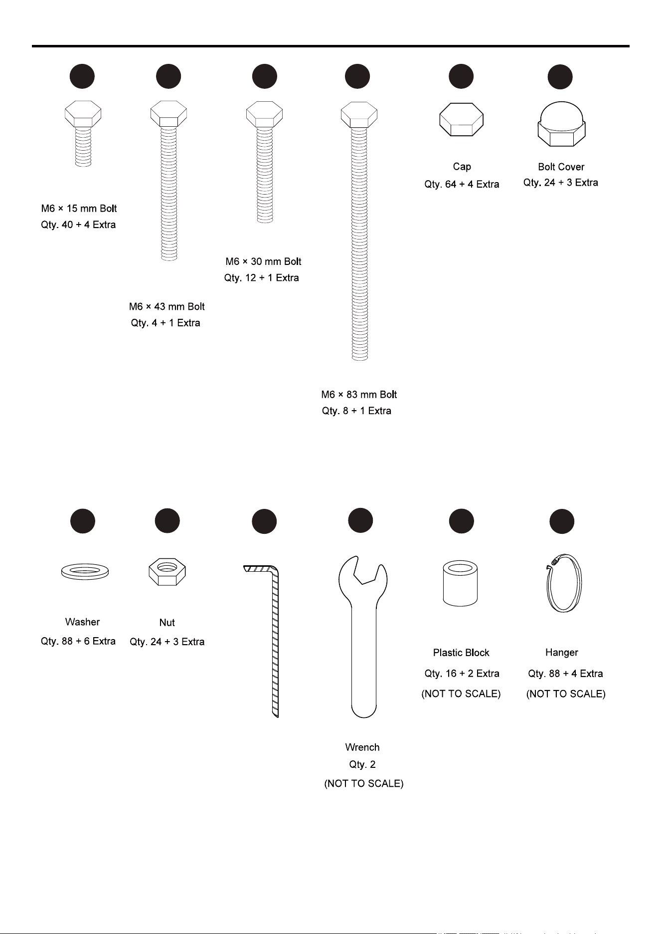
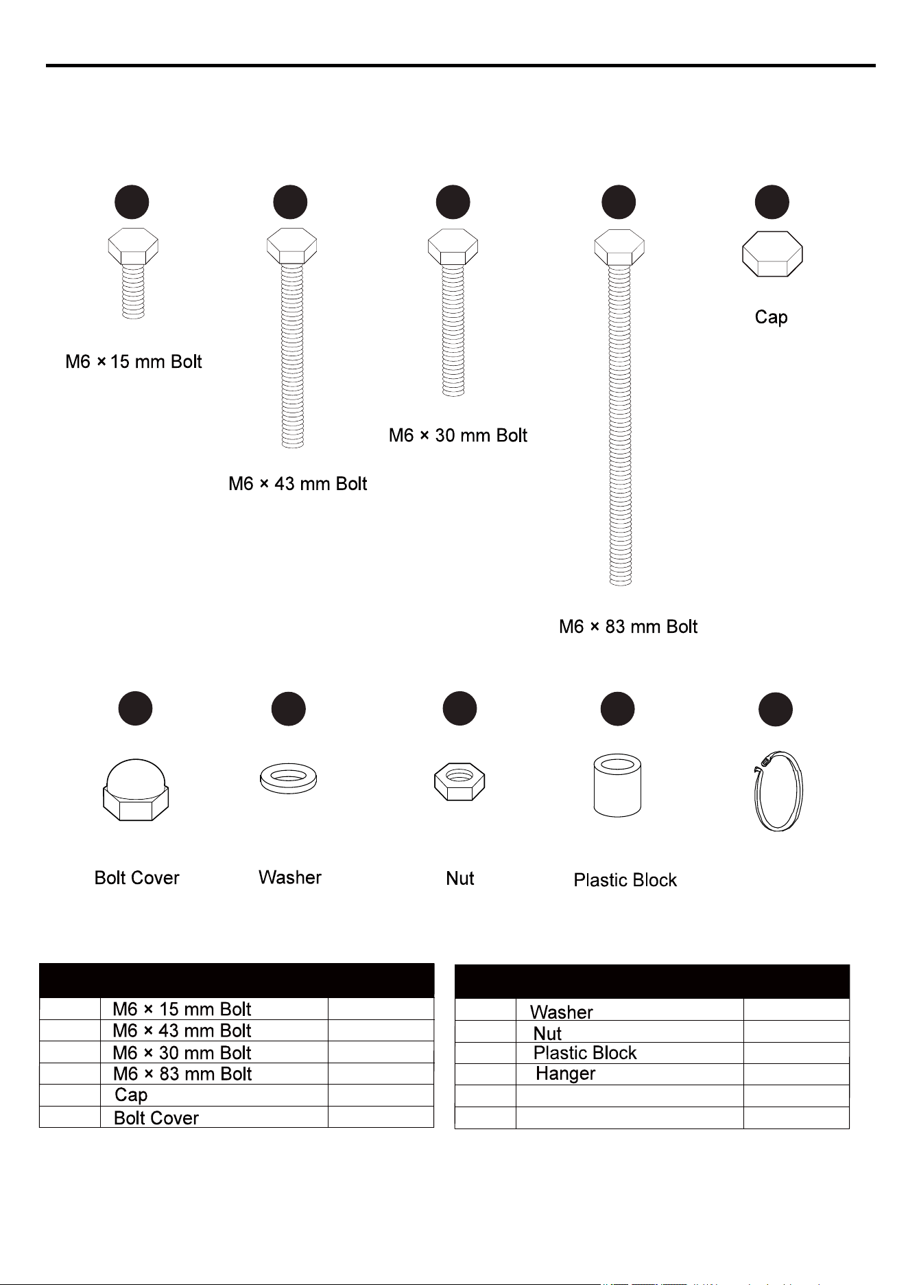
HARDWARE CONTENTS (shown actual size)
5
AA
GG
EE
Washer
Cap
Wrench
KEEP ALL FLAME AND HEAT AWAY FROM THIS TENT FABRIC.
A
C
C
B
EE
EE
AA
GG
B
AA
Please read and understand this entire manual before attempting to assemble or install the product.
Two to four people are need for assembly.
Maximum load for the roof hook: 50 lbs.
.
.
.
.
.
SAFETY INFORMATION
WARNING:
CAUTION
PREPARTION
ASSEMBLY INSTRUCTIONS
Hardware Used
This tent meets the flammability requirements of CPAI-84. The fabric may burn if left in continuous
contact with any flame source. The application of any foreign substance to the tent fabric may
render the flame-resistant properties ineffective.
Do not leave outside during high winds, heavy rains or snow. If high winds, heavy rains or any
snow occurs, remove canopy, mosquito net and curtain, clear snow load from roof tube, and
check for damage before continued use.
Before beginning assembly of product, make sure all parts are present. Compare parts with package
contents list and hardware contents list. If any part is missing or damaged, do not attempt to assemble
the product.
Estimated Assembly Time: 2-3 hours
Tools Required for Assembly (not included): Ladder
Tools Required for Assembly ( included): Wrench
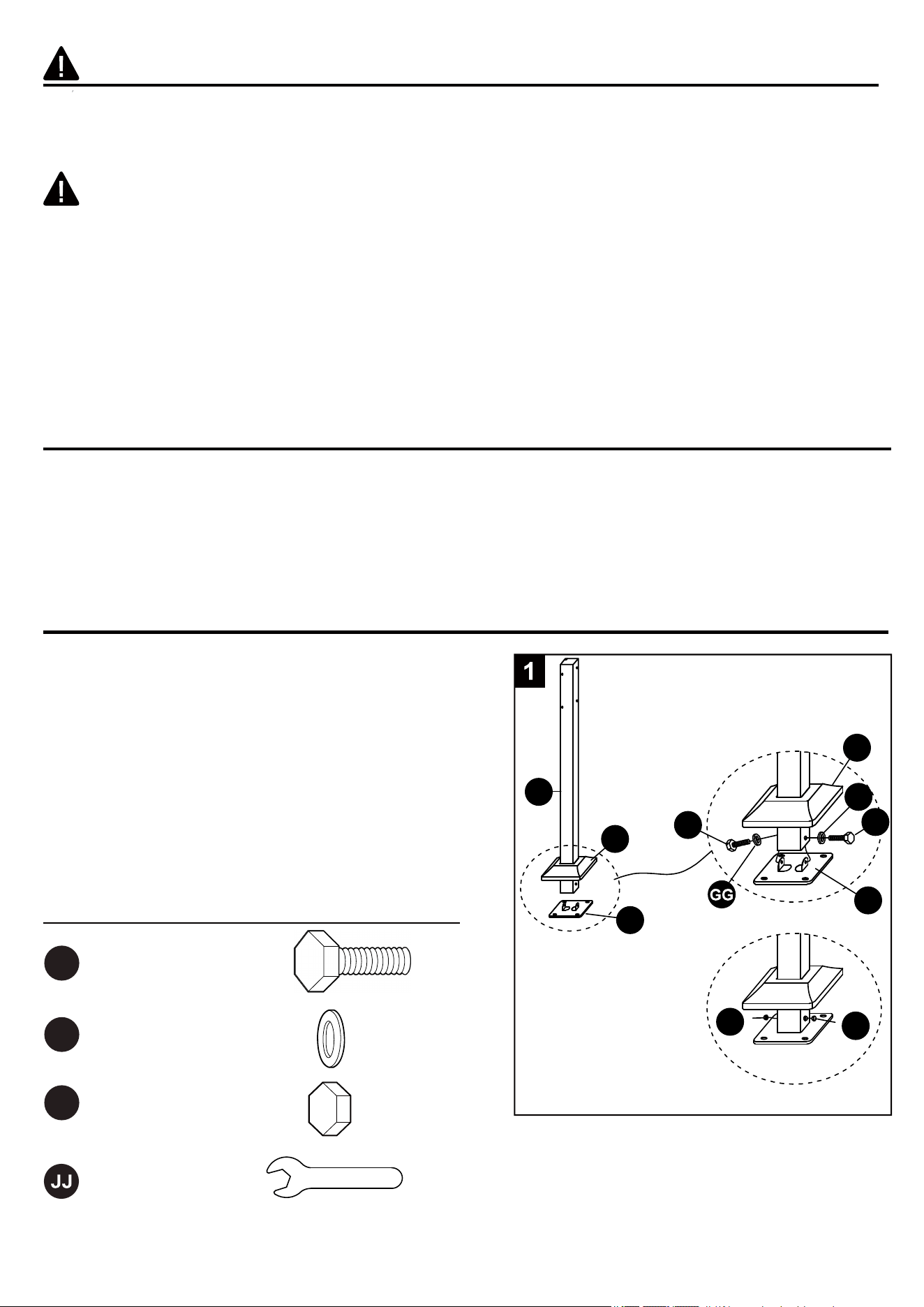
1. Insert the post plate cover (C) into the supporting
post (A). Fit the post bottom plate (B) underneath
the supporting post (A). Insert two M6 x 15 mm bolts
(AA) into the washers (GG), supporting post (A) and
secure to the post bottom plate (B) using the
wrench (JJ), but do not overtighten. Place caps
(EE) on the bolt heads. Slide the post plate cover
(C) down into place.
Repeat this step for the remaining supporting posts
(A), post bottom plates (B) and post plate covers (C).
M6 x 15 mm Bolt
6
2
BB
GG
HH
EE
FF
JJ
BB
GG
HH
GG
Wrench
ASSEMBLY INSTRUCTIONS
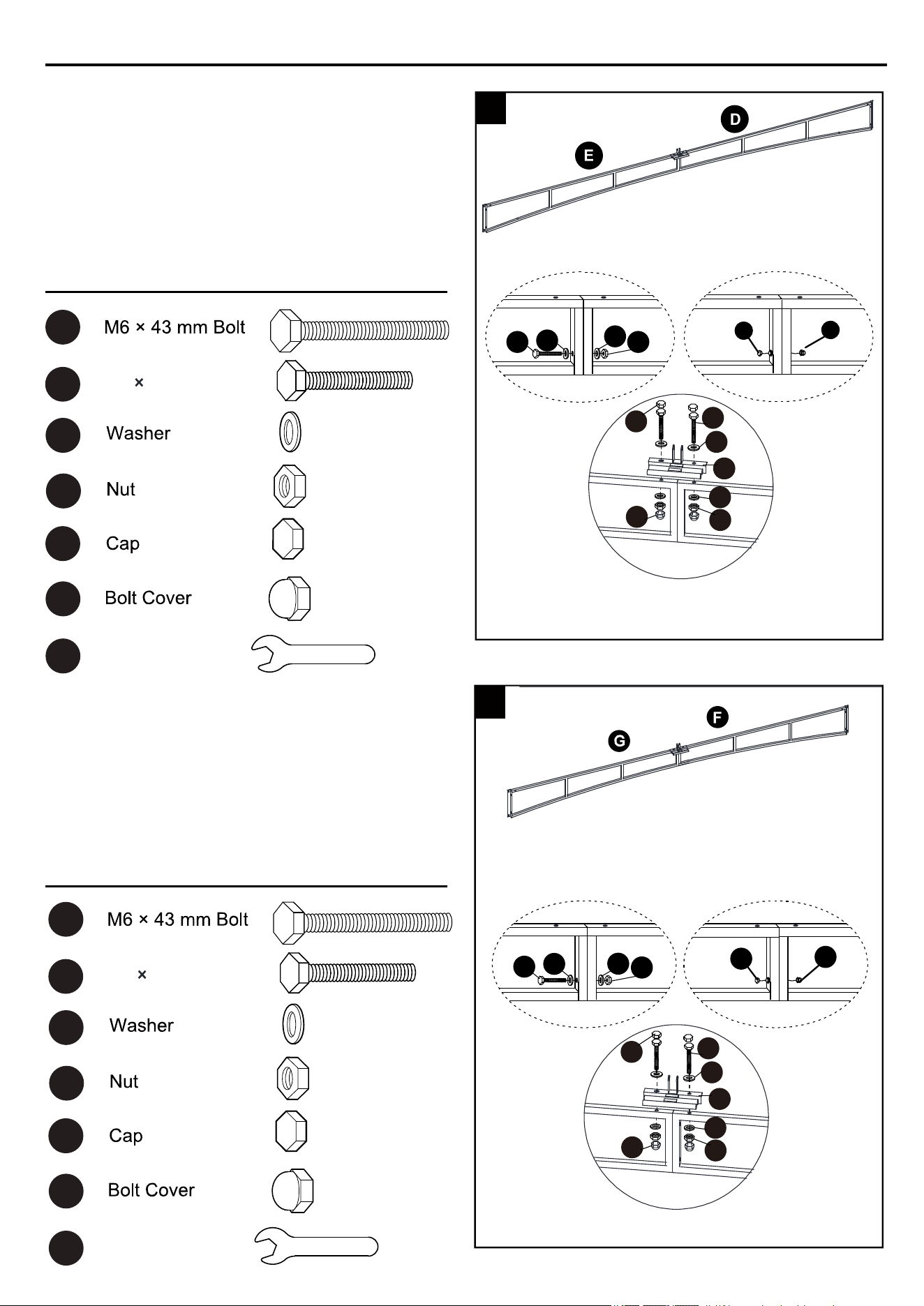
Insert long right crossbar (E) into long left crossbar (D).
Secure together using M6 x 43mm bolt (BB),
washers (GG) and nut (HH). Tighten securely with the
wrench (JJ). Place cap (EE) on the bolt head and
place bolt cover (FF) on the nut (HH).
Connect the connector (T) onto the crossbar by
bolt (CC), washer (GG), nut (HH). Cover bolt cover
(FF) and cap (EE).
Connect the connector (T) onto the crossbar by
bolt (CC), washer (GG), nut (HH). Cover bolt cover
(FF) and cap (EE).
Hardware Used
Hardware Used
3. Insert short right crossbar (G) into short left crossbar (F).
Secure together using M6 x 43 mm bolt (BB),
washers (GG) and nut (HH). Tighten securely with the
wrench (JJ). Place cap (EE) on the bolt head and place
bolt cover (FF) on the nut (HH).
2.
2
3
EE
FF
BB
GG
HH
GG
EE
FF
GG
T
CC
EE
HH
FF
GG
GG
T
CC
EE
HH
FF
GG
M6 30mm Bolt
CC
BB
GG
HH
EE
FF
JJ
Wrench
M6 30mm Bolt
CC
7
ASSEMBLY INSTRUCTIONS
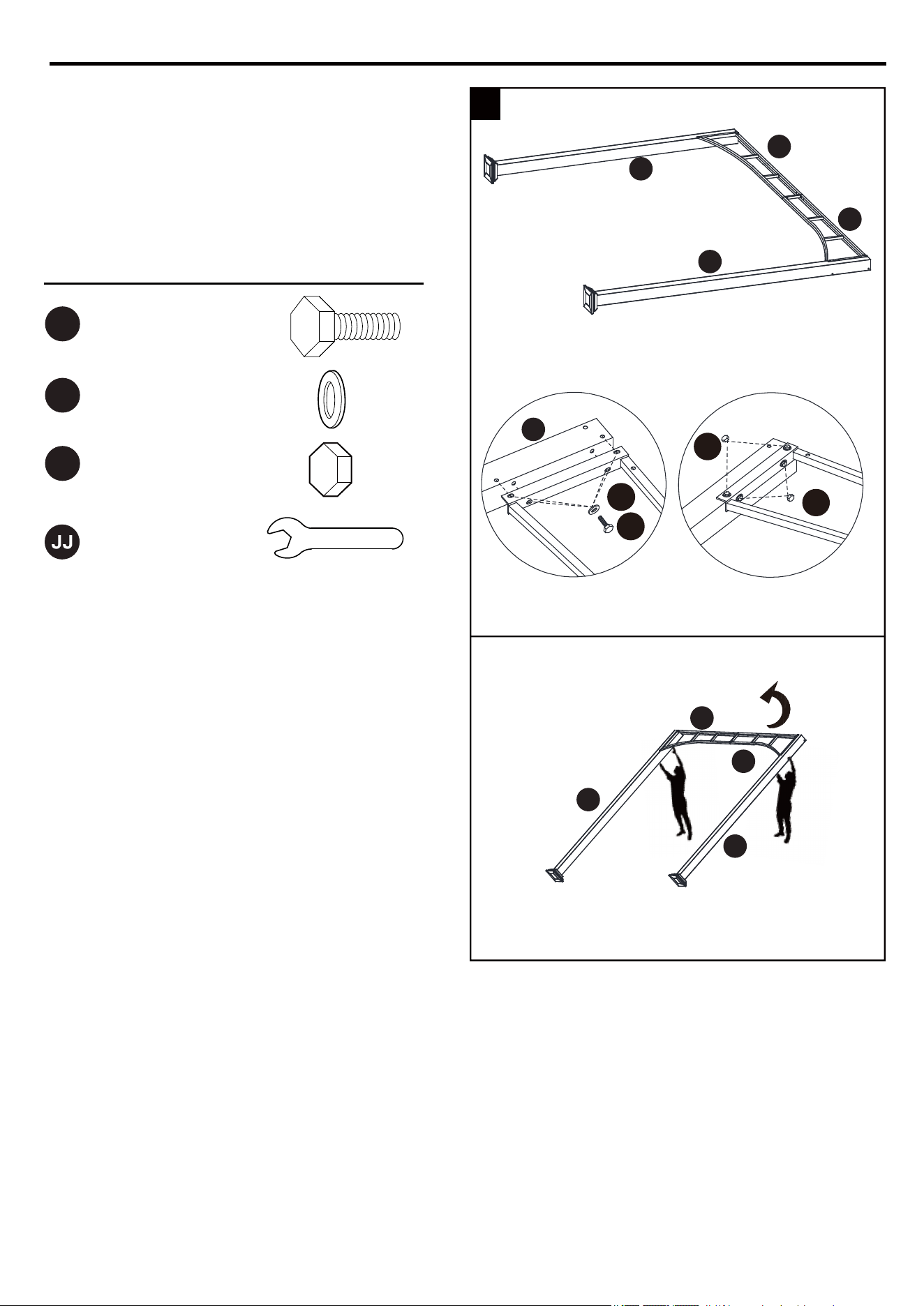
4. Secure the crossbar assemblies to the
4
D
E
D
E
A
A
A
A
A
supporting posts (A) using M6 x 15 mm
bolts (AA) and washers (GG). Tighten
securely with the wrench (JJ). Place caps
(EE) on the bolt heads.
Stand the assembled structure of posts (A)
and crossbar up by two people.
EE
EE
GG
AA
AA
GG
EE
Washer
Cap
Wrench
Hardware Used
M6 x 15 mm Bolt
8
ASSEMBLY INSTRUCTIONS
Washer
Cap
M6 83mm BoltDD
GG
EE
JJ Wrench
Hardware Used
D
F/G
E
F
A
A
A
A
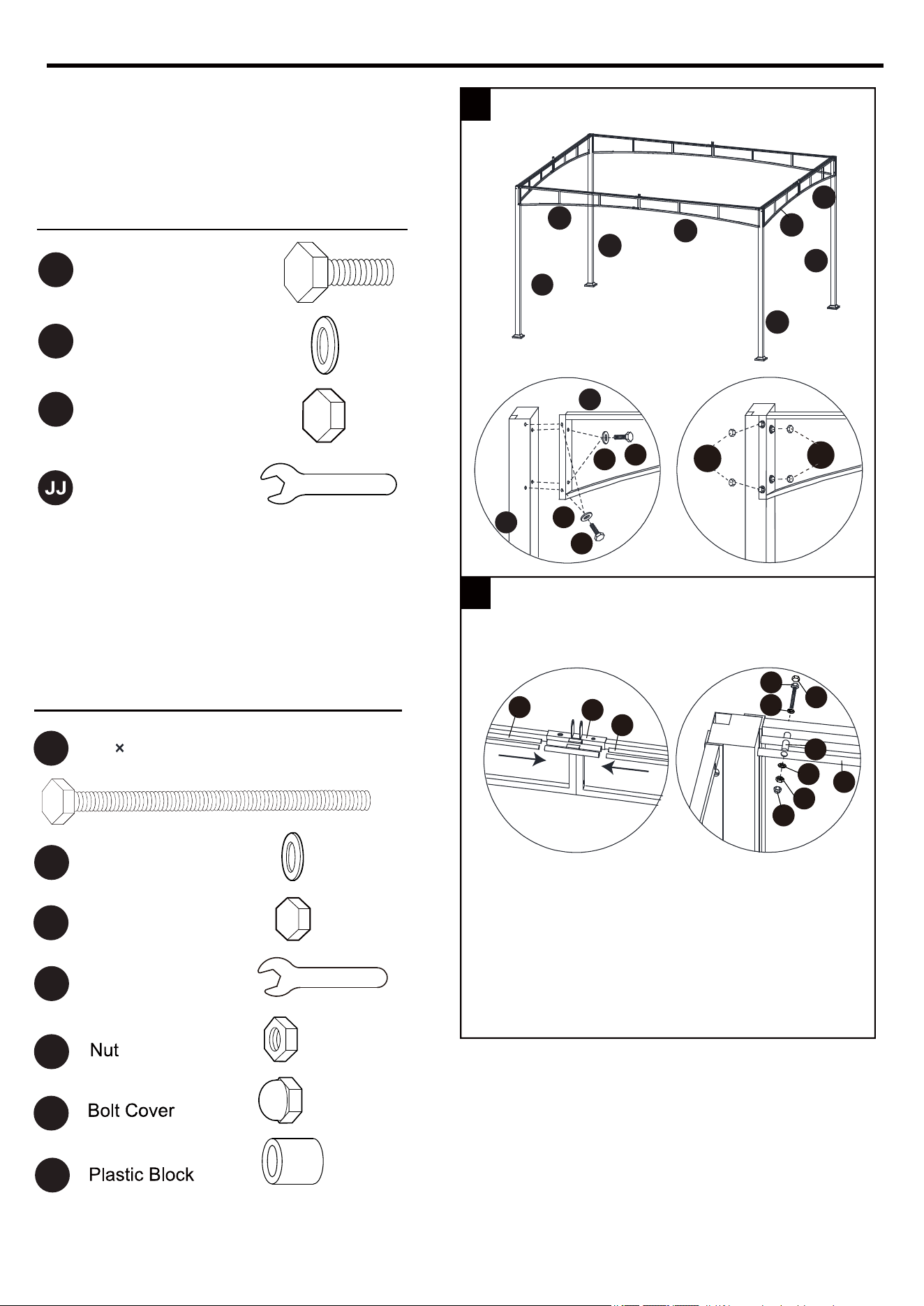
5. Secure the crossbar assemblies to the
supporting posts (A) using M6 x 15 mm
bolts (AA) and washers (GG). Tighten
securely with the wrench (JJ). Place caps
(EE) on the bolt heads.
6. Slide one end of the rail (U/V) into the
connector (T), fix the other end of it onto the
crossbars by bolt (DD) washer (GG), nut (HH).
Cover bolt cover (FF) and cap (EE).
EE
EE
GG
T
U/V
AA
FF
HH
GG
GG
DD
EE
GG
AA
5
6
G
AA
GG
EE
Washer
Cap
Wrench
Hardware Used
M6 x 15 mm Bolt
HH
FF
KK
KK
U/V
U/V
A

ASSEMBLY INSTRUCTIONS
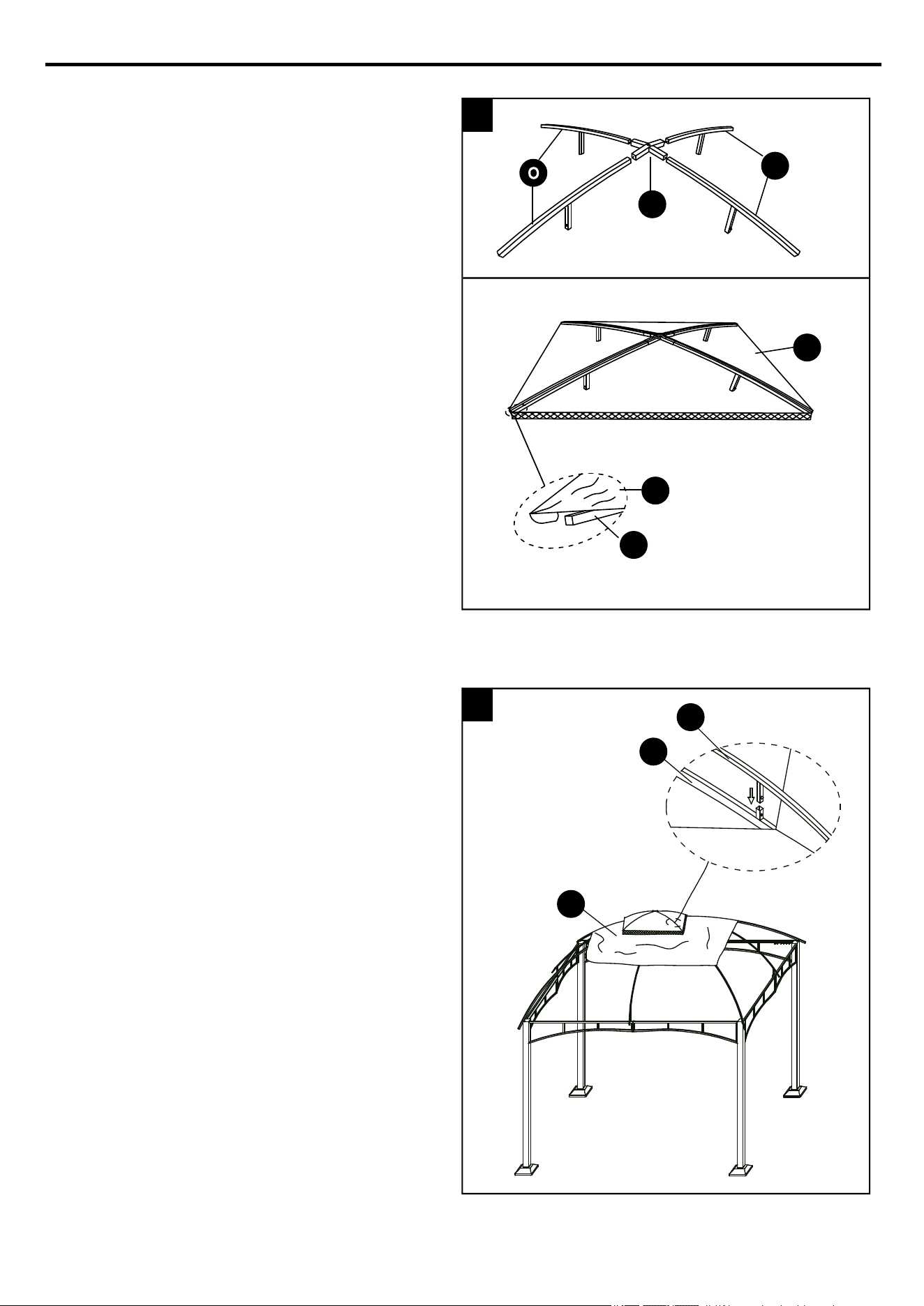
7. Insert each small connector pole (K) into each
long top connector pole (J).
8. Screw the hook (I) into the roof connector (H)
and twist counterclockwise to tighten.
K
J
H
I
7
8
9
ASSEMBLY INSTRUCTIONS
10
J
H
H
J
K
K
K
J
K
J
K
A
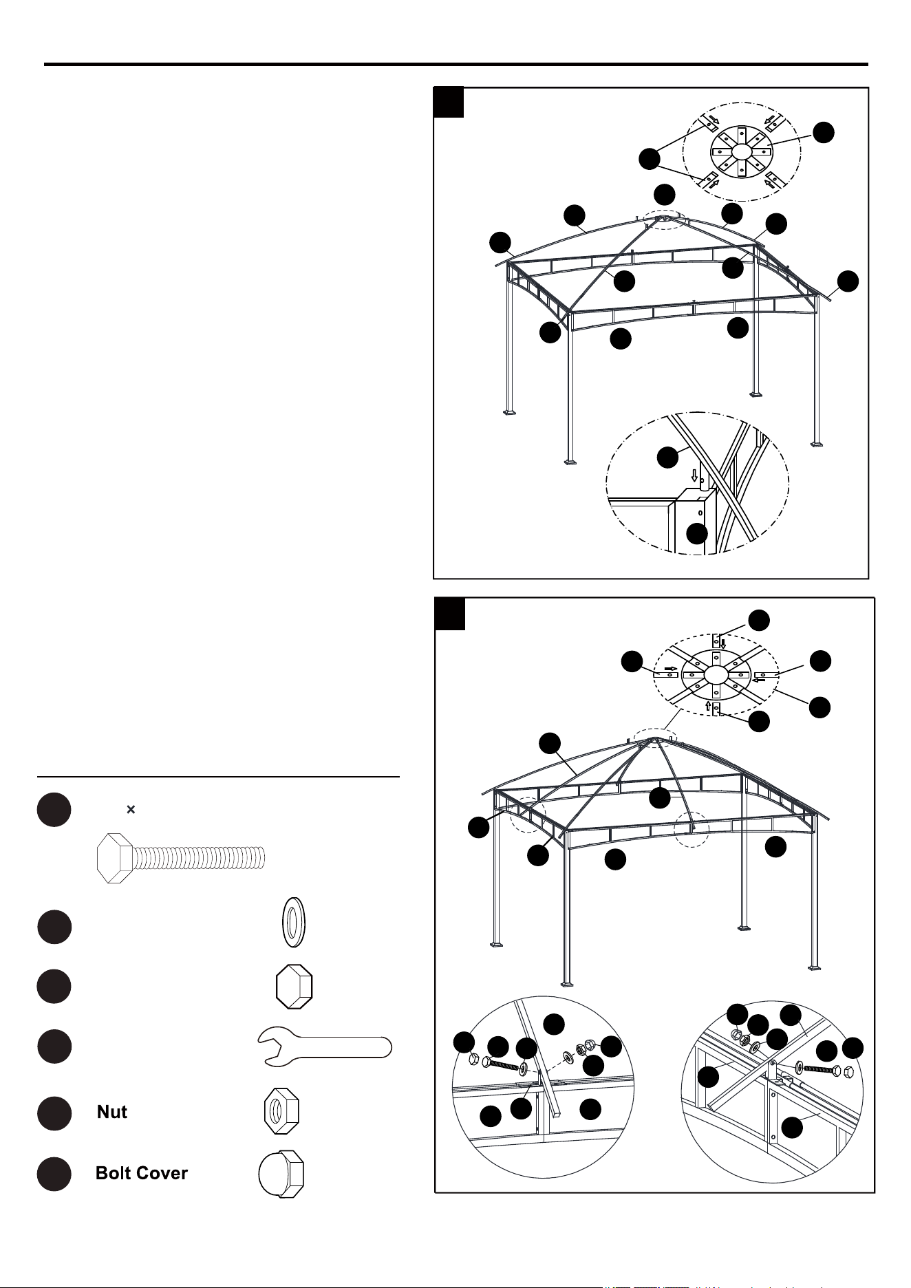
9. Insert each long top connector pole (J) into
roof connector (H). Then insert each small
connector pole (K) into supporting posts (A).
Slide one end of the short top pole (L) into
the roof connector (H), the other end of it
should be fixed onto the connector (T) by
bolt (CC/GG/HH). Slide one end of the short
top pole (M) into the roof connector (H),
the other end of it should be fixed onto the
connector (T) by bolt (CC).
9
M
L
M
M
L
L
H
G
G
CC
CC
D
D
E
E
E
F
M
10.
10
L
J
D
T
F
Washer
Cap
M6 30mm Bolt
CC
GG
EE
JJ Wrench
Hardware Used
HH
FF
EE
EE
HH
HH
GG
GG
FF
FF
11
N
O
O
P
O
J
Q
O
ASSEMBLY INSTRUCTIONS
11. Insert each small top beam (O) into small
top connector (N). Attach the air vent cover
(Q) on the small top beam (O).
fo pot no ylesool )P( revoc cirbaf eht ecalP .21
the assembly. Insert each small top beam
(O) into the long top connector pole (J).
Note: Put each small top beam (O) loosely
on each long top connector pole (J) first,
then insert together, otherwise the last one
won’t insert correctly.
11
12
Q

II
Stake
LL
Hanger
revo gnillup yb )P( revoc cirbaf eht nethgiT .31
the four small connector poles as shown.
15. Insert stakes (II) through the holes in the post
bottom plates (B) and into the ground to
secure the gazebo.
Note: This gazebo can be secured to the
deck (wood or concrete), but customers
need to prepare the appropriate hardware
(expansion bolts or sheet-metal screws) for
fixing.
R
S
L/M
K
P
P
P
A
C
B
LL
LL
U/V
U/V
II
ASSEMBLY INSTRUCTIONS
Note: Be mindful of the tag hanging on the
zipper of mosquito net (S) and curtain (R).
This tag indicates which side is 12 ft. and
which side is 10 ft.
ATTENTION: Keep the curtain outside and
the mosquito net inside during assembly.
Close the zippers on the curtain and mosquito
net before hanging them. If they need to be
removed, make sure the zippers are closed
first.
13
14
S
S
R
R
12
12
14. Hang the curtain (R) and mosquito net (S)
on the rail (U/V) using the hanger (LL)
preassembled on the crossbars.

1. It is the manufacturer’s recommendation to
remove the canopy during high winds, heavy
rains or snow. To do so, simply reverse the
order of instructional steps 11 - 13 ASSEMBLY
INSTRUCTIONS on page 11 - 12.
1
P
Q
O
ASSEMBLY INSTRUCTIONS
.
.
.
Slight pinholes will be present in the tubing, which is customary of original steel work and should not
be considered.
Wash with soap and water.
Before storing, remove leaves and dirt, drain all water that may have accumulated in or around the
frame. If not
drained properly, water can cause freeze damage including bursting or cracking of
metal tubing.
CARE AND MAINTENANCE
1
This warranty is extended to the original purchaser and applies to defects in materials and
workmanship of your outdoor furniture or accessory item(s), provided it is maintained with care and
used only for personal, residential purposes.
Frames and welds are warranted to be free from defects in material or workmanship for a period of
one year.
Fabric is warranted for a period of one year against defects in material or workmanship.
This warranty is not transferable and does not cover products damaged by misuse, neglect,
accident, alterations or use and maintenance other than that specified in this instruction.
The manufacturer will not be held liable for any direct, indirect, incidental or consequential damages.
Some states do not allow limitations on how an implied warranty lasts, or the exclusion or limitation
of incidental
or consequential damages, so the above limitations may not apply to you.
This warranty gives you specific legal rights, and you may also have other rights which vary from
state to state.
U. S. A. Customers: Replacement canopies are available for purchase at www.Lowes.com.
.
.
.
.
.
.
.
13
WARRANTY
For replacement parts, call our customer service department at 1-866-439-9800, 8 a.m. - 8 p.m.,
EST, Monday - Sunday. You could also contact us at [email protected] or visit
www.lowespartsplus.com.
REPLACEMENT PARTS LIST
Printed in China
14
PART DESCRIPTION PART#
AA
BB
CC
DD
EE
FF
4
1
1
1
4
3
PART DESCRIPTION PART#
GG
HH
KK
LL
6
3
2
4
Hanger
AA CCBB DD EE
GG
HH
KK
LL
FF
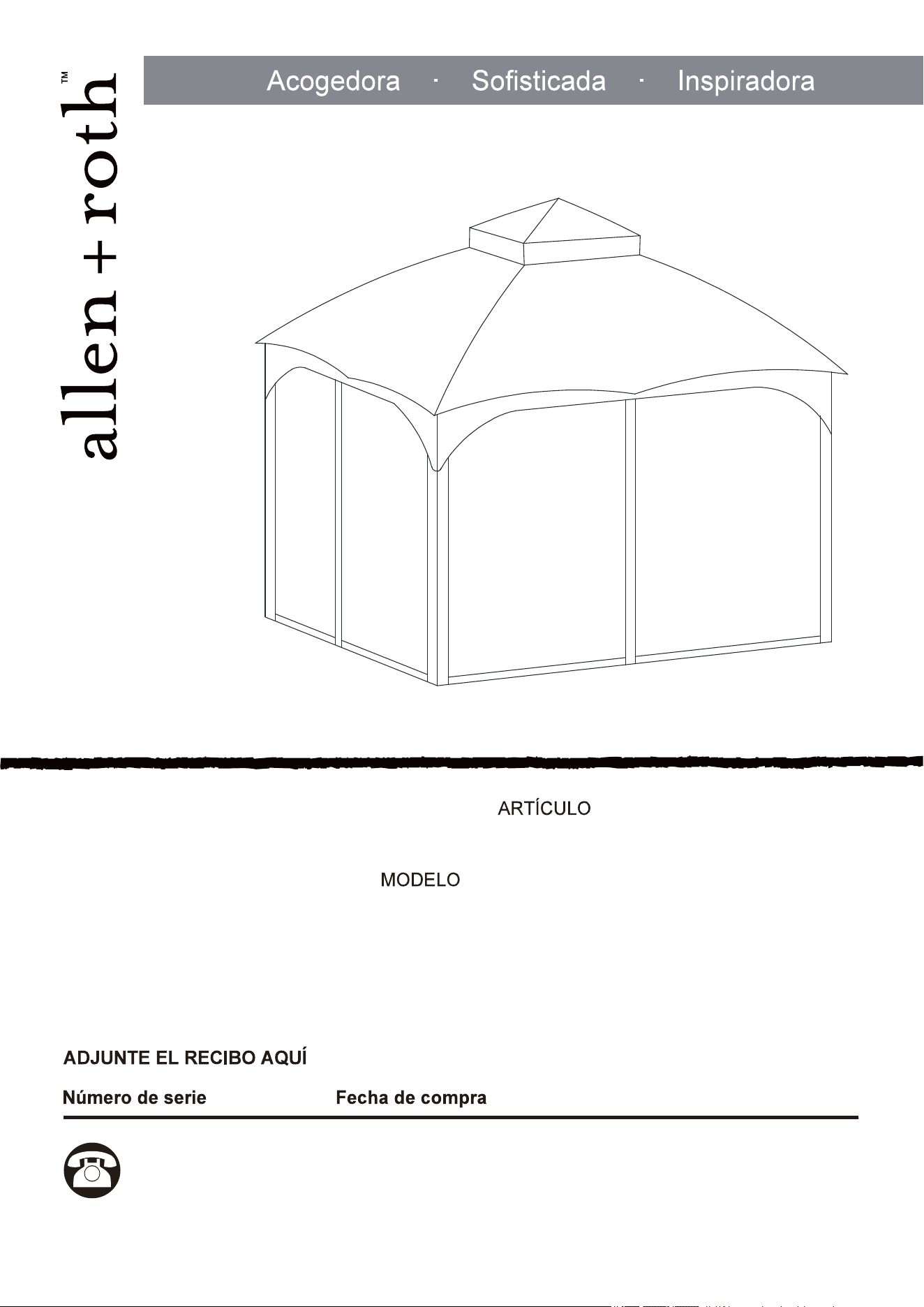
#4134949/ #4115489/ #4115490
GAZEBO DE CUBIERTA SUAVE
#TPGAZ2303D/ #TPGAZ2403A/ #TPGAZ2403C
15
___________ ___________
¿Preguntas, problemas, piezas faltantes? Antes de volver a la tienda, llame a nuestro
Departamento de Servicio al Cliente al 1-866-439-9800, de lunes a domingo de 8 a.m.
a 8 p.m., hora estándar del Este. También puede ponerse en contacto con nosotros en
[email protected] o visitar www.lowespartsplus.com.
ALLEN + ROTH y el diseño del logo son marcas
comerciales o marcas registradas de LF, LLC.
Todos los derechos reservados.
16
ÍNDICE
DESCRIPTION
17
D
Q
E
F
G
H
N
O
P
A
C
B
S
R
M
T
U
V
L
K
I
J
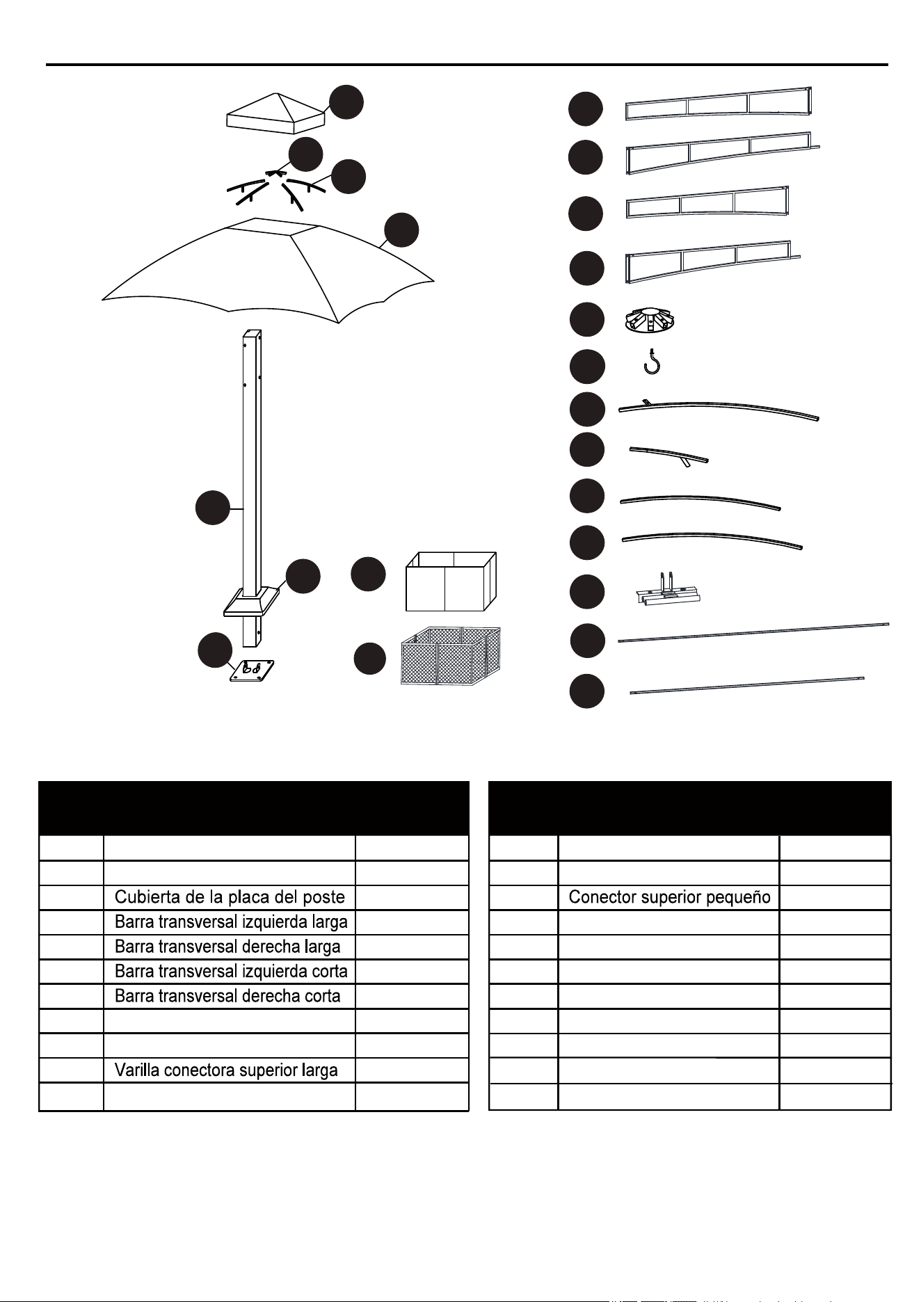
CONTENIDO DEL PAQUETE
PART PART
Poste de apoyo
Placa inferior del poste
Conector para techo
Gancho
Varilla conectora pequeña
A
B
C
D
E
F
G
H
I
J
K
4
4
4
2
2
2
2
1
1
4
4
Varilla superior corta
Varilla superior corta
Cubierta para perno
Cubierta del respiradero
Cubierta de tela
Mosquitero
Conector
Riel
Riel
Pared lateral
2
2
1
4
1
1
4
4
4
8
8
PIEZA
DESCRIPCIÓN
CANTIDAD
PIEZA
DESCRIPCIÓN
CANTIDAD
L
M
N
O
Q
P
R
S
T
U
V
18
(NO ESTÁ
A ESCALA)
(NO ESTÁ
A ESCALA)
AA CCBB DD EE
GG
II
HH
JJ
KK
LL
FF
Estaca
Cant. 16
(NO ESTÁ
A ESCALA)
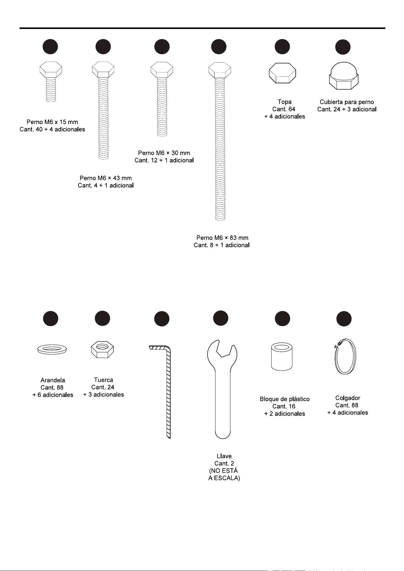
ADITAMENTOS (se muestran en tamaño real)
19
AA
GG
EE
MANTENGA LA TELA DE LA TIENDA DE CAMPAÑA ALEJADA DE LAS LLAMAS Y
DEL CALOR.
A
C
C
B
EE
EE
AA
GG
B
AA
Lea y comprenda completamente este manual antes de intentar ensamblar o instalar el producto.
Para realizar el ensamblaje se necesitan de dos a cuatro personas.
Carga máxima pare el gancho del techo: 22, 67 kg.
.
.
.
.
.
INFORMACIÓN DE SEGURIDAD
ADVERTENCIA:
PRECAUCIÓN
PREPARACIÓN
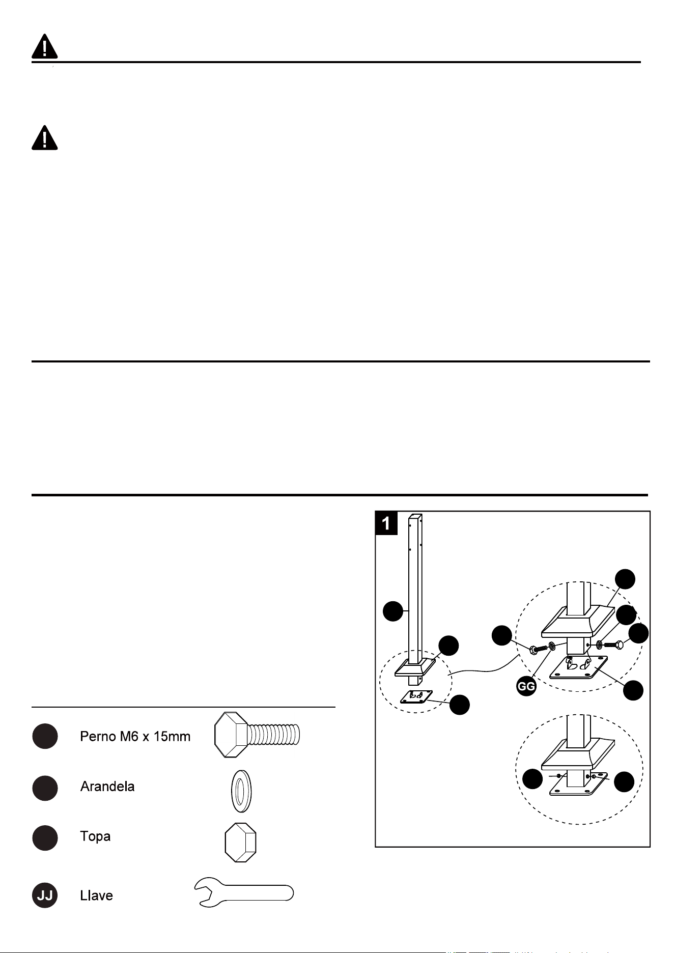
INSTRUCCIONES DE ENSAMBLAJE
Aditamentos utilizados
Esta tienda de campaña cumple con los requisitos de inflamabilidad de la norma CPAI-84. La
tela podría arder si se encuentra en continuo contacto con cualquier fuente de calor. La
aplicación de cualquier sustancia extraña a la tela de la tienda de campaña puede hacer que
sus propiedades ignífugas se anulen.
No lo deje afuera si hay vientos fuertes, lluvia torrencial o nieve. Si hay vientos fuertes, lluvia
torrencial o nieve, retire el toldo, el mosquitero y la cortina, limpie la carga de nieve del tubo
del techo y revise si hay daños antes de continuar el uso.
Antes de comenzar a ensamblar el producto, aseqúrese de tener todas las piezas. Compare las
piezas con la lista del contenido del paquete y la lista de aditamentos. No intente ensamblar el
producto si falta alguna pieza o si estas están dañadas.
Tiempo estimado de ensamblaje: 2 a 3 horas
Herramientas necesarias para el ensamblaje (no se incluyen): escalera.
Herramientas necesarias para el ensamblaje (se incluyen): llave.
1. Inserte la cubierta de la placa del poste (C) en el
poste de apoyo (A). Calce la placa inferior del poste (B)
bajo el poste de apoyo (A). Inserte dos pernos M6 x 15
(AA) en la arandela (GG) en el poste de apoyo (A) y
asegure a la placa inferior del poste (B) utilizando la
llave(JJ), pero sin apretar demasiado. Coloque la topa
(EE) en la cabeza del perno. Deslice la cubierta de la
placa del poste (C) hasta su lugar.
Repita este paso para los postes de apoyo (A), las
placas inferiores del poste (B) y las cubiertas de la
placa del poste (C) restantes.
20
2
BB
GG
HH
EE
FF
JJ
BB
GG
HH
GG
LIave
INSTRUCCIONES DE ENSAMBLAJE
Aditamentos utilizados
Aditamentos utilizados
2
3
EE
FF
BB
GG
HH
GG
EE
FF
GG
T
CC
EE
HH
FF
GG
GG
T
CC
EE
HH
FF
GG
M6 × 30 mm
CC
BB
GG
HH
EE
FF
JJ
LIave
M6 × 30 mm
CC
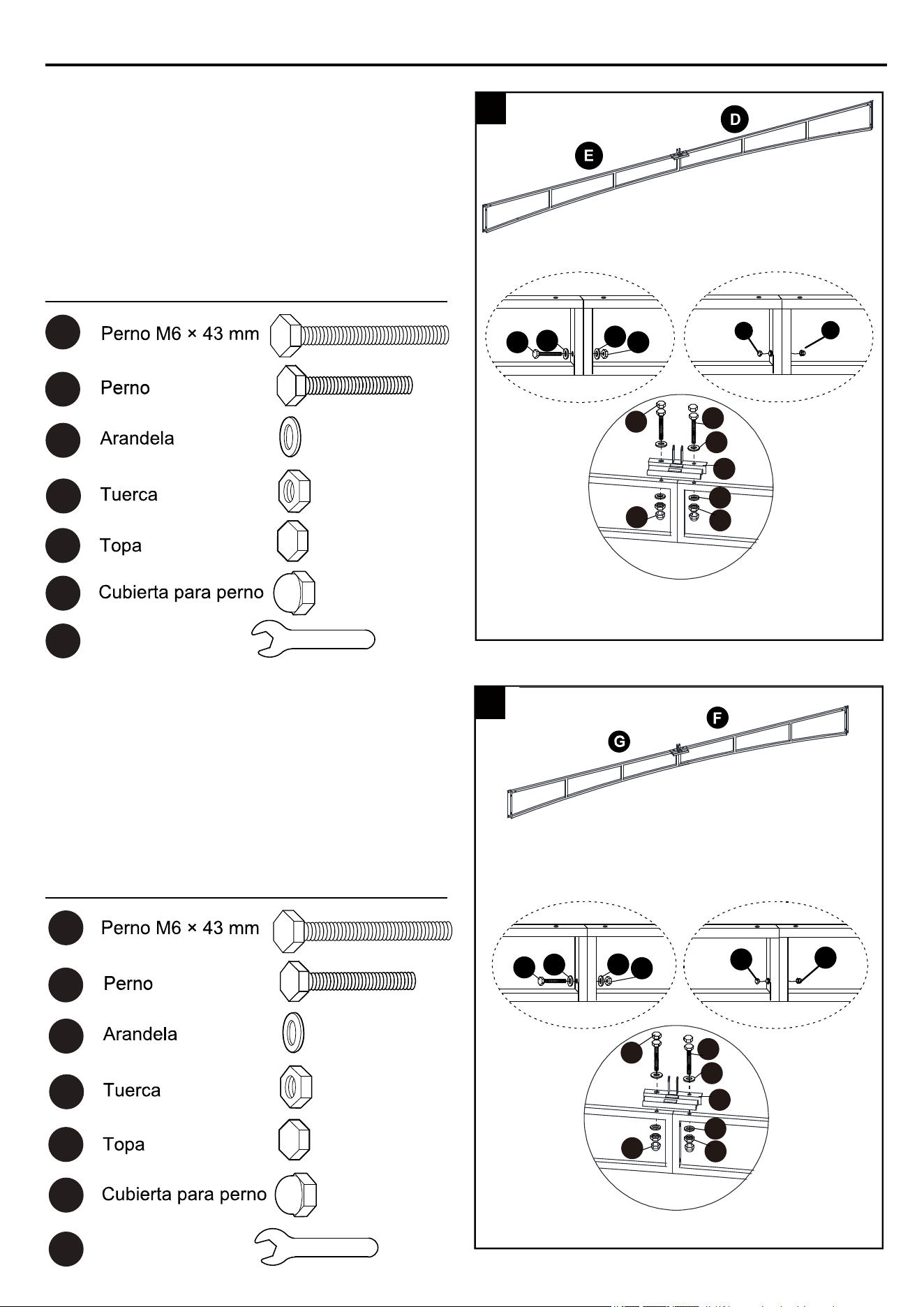
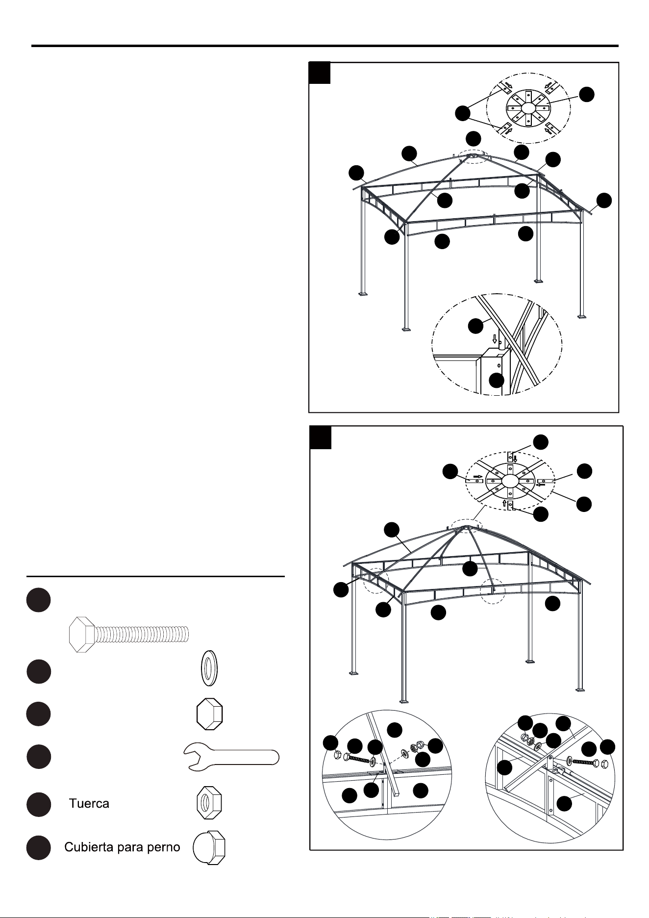
2. Inserte la barra transversal derecha larga (E) en
la barra transversal izquierda larga (D).
Asegure y únalas usando pernos M6 x 43mm
(BB), arandelas (GG) y tuercas (HH). Apriete
firmemente con la llave (JJ). Coloque la topa (EE)
en la cabeza del perno y coloque la cubierta para
pernos (FF) en la tuerca (HH).
Una el conector (T) al travesaño con un perno (CC),
una arandela (GG) y una tuerca (HH). Coloque la
cubierta del perno (FF) y la topa (EE).
3. Inserte la barra transversal derecha corta (G) en
la barra transversal izquierda corta (F). Asegure
y únalas usando pernos M6 x 43 mm (BB),
arandelas (GG) y tuercas (HH). Apriete
firmemente con la llave (JJ). Coloque la topa
(EE) en la cabeza de perno y coloque la
cubierta para pernos (FF) en la tuerca (HH).
Una el conector (T) al travesaño con un perno (CC),
una arandela (GG) y una tuerca (HH). Coloque la
cubierta del perno (FF) y la topa (EE).
21
INSTRUCCIONES DE ENSAMBLAJE
4
D
E
D
E
A
A
A
A
A
EE
EE
GG
AA
AA
GG
EE
Arandela
Topa
LIave
Aditamentos utilizados
Perno M6 ×15 mm
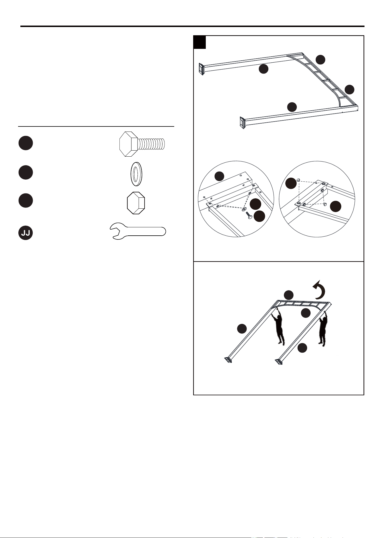
4. Asegure los ensambles de las barras
transversales a los postes de apoyo (A) con
pernos M6 x 15 mm (AA) y las arandelas (GG).
Apriete firmemente con la llave (JJ). Coloque
la topa (EE) en la cabeza del perno.
Con dos personas, levante la estructura
ensamblada de postes (A) y la barra
transversal.
22
INSTRUCCIONES DE ENSAMBLAJE
Arandela
Topa
Perno M6 × 83 mmDD
GG
EE
JJ LIave
Aditamentos utilizados
D
F/G
E
F
A
A
A
A
6. Deslice un extremo del riel (U/V) en el
conector (T), fije el otro extremo en el
travesaño con un Perno (DD), una arandela
(GG) y una tuerca (HH). Coloque la cubierta
del perno (FF) y la topa (EE).
EE
EE
GG
T
U/V
AA
FF
HH
GG
GG
DD
EE
GG
AA
5
6
G
AA
GG
EE
Arandela
Topa
LIave
Aditamentos utilizados
Perno M6 ×15 mm
HH
FF
KK
KK
U/V
U/V
A
5. Asegure los ensambles de las barras
transversales a los postes de apoyo (A) con
pernos M6 x 15 mm (AA) y las arandelas (GG).
Apriete firmemente con la llave (JJ). Coloque
la topa (EE) en la cabeza del perno.
INSTRUCCIONES DE ENSAMBLAJE
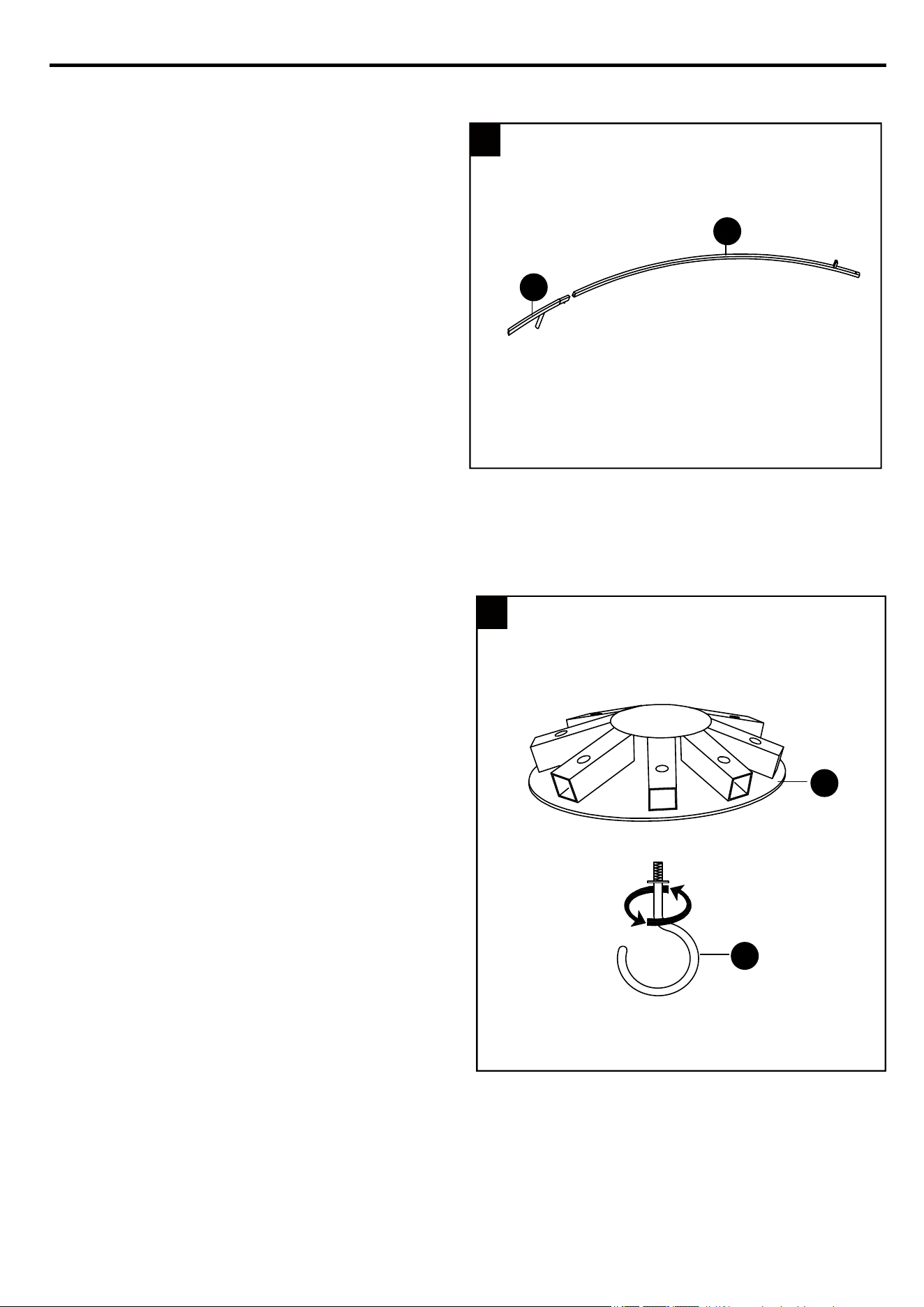
7. Inserte cada varilla conectora pequeña (K) en
cada varilla conectora superior larga (J).
8. Enrosque el gancho (I) en el conector del
techo (H) y gire en dirección contraria a
las manecillas del reloj para apretar.
K
J
H
I
7
8
23
INSTRUCCIONES DE ENSAMBLAJE
24
J
H
H
J
K
K
K
J
K
J
K
A
9. Inserte cada varilla conectora superior
larga (J) en el conector del techo (H).
Luego, inserte cada varilla conectora
pequeña (K) en los postes de apoyo (A).
Deslice un extremo de la varilla superior
corta (L) en el conector del techo (H), el
otro extremo debe fijarse en el conector
(T) con un perno (CC/GG/HH). Deslice un
extremo de la varilla superior corta (M) en
el conector del techo (H), el otro extremo
debe fijarse en el conector (T) con un
perno (CC).
9
M
L
M
M
L
L
H
G
G
CC
CC
D
D
E
E
E
F
M
10.
10
L
J
D
T
F
Arandela
Topa
Perno M6 × 30 mm
CC
GG
EE
JJ LIave
Aditamentos utilizados
HH
FF
EE
EE
HH
HH
GG
GG
FF
FF

25
N
O
O
P
O
J
Q
O
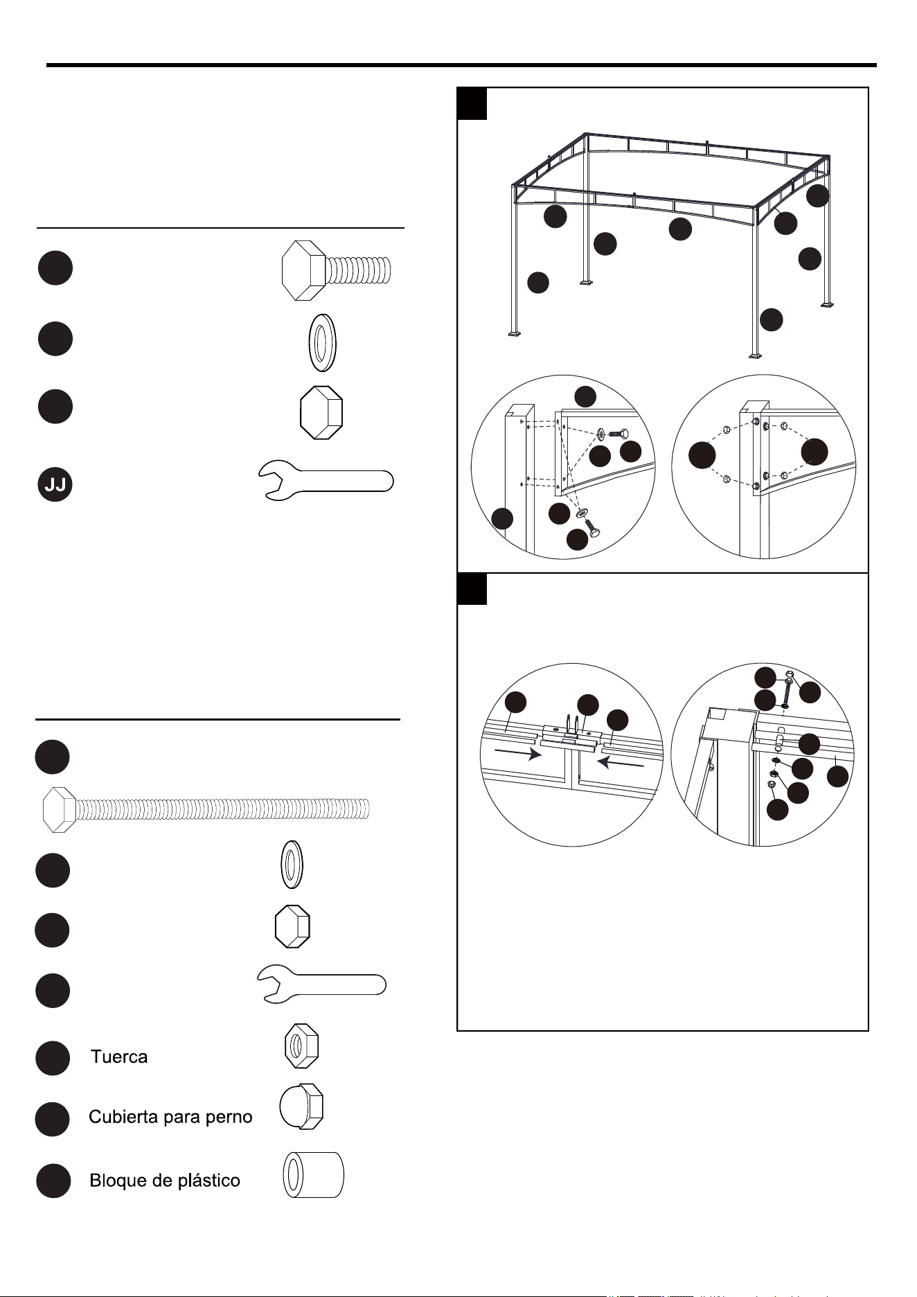
INSTRUCCIONES DE ENSAMBLAJE
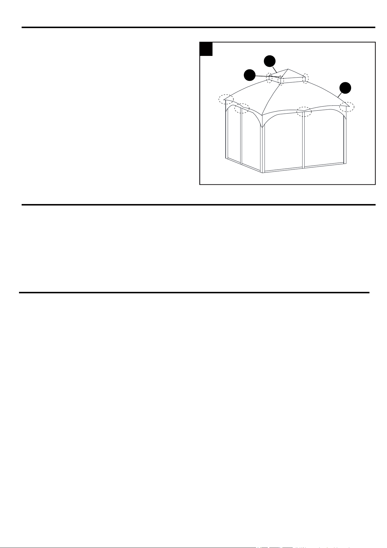
11. Inserte cada viga superior pequeña (O) en
el conector superior pequeño (N). Fije la
cubierta del respiradero (Q) en la viga
superior pequeña (O).
Coloque la cubierta de la tela (P) de forma
suelta en la parte superior del ensamble.
Inserte cada viga superior pequeña (O) en
la varilla conectora superior larga (J).
Nota: coloque cada viga superior pequeña
(O) sin apretar en cada varilla conectora
superior larga (J) primero, luego insértelas
juntas, de lo contrario, la última no se
insertará correctamente.
.21
11
12
Q
II
Estaca
LL
Colgador
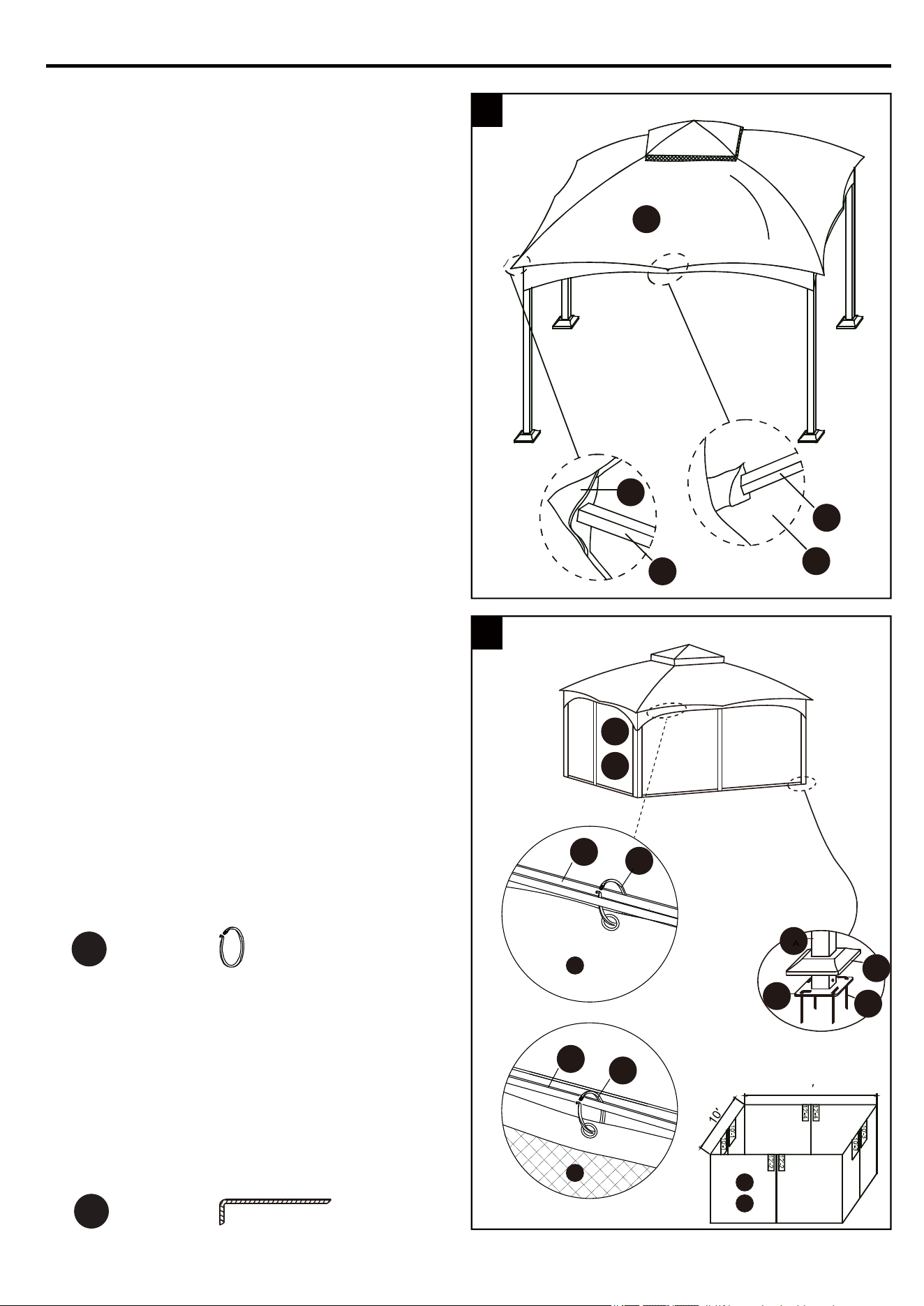
Apriete la cubierta de tela (P) jalándola sobre
las cuatro varillas conectoras pequeñas, como
se muestra.
.31
15. Pase las estacas (II) por los orificios en las
placas inferiores de los postes (B) y en el suelo
para asegurar el gazebo.
Nota: este gazebo se puede fijar a la terraza
(madera o concreto), pero los clientes deben
preparar los aditamentos adecuados (pernos
de expansión o tornillos para láminas de metal)
para fijar.
R
S
L/M
K
P
P
P
A
C
B
LL
LL
U/V
U/V
II
INSTRUCCIONES DE ENSAMBLAJE
Nota: tenga en cuenta la etiqueta que cuelga
de la cremallera del mosquitero (S) y la
cortina (R). Esta etiqueta indica qué lado
mide 3,65 m y qué lado mide 3,04 m.
ATENCIÓN: mantenga la pared lateral
afuera y el mosquitero dentro durante el
ensamblaje. Cierre las cremalleras en la
pared lateral y el mosquitero antes de
colgarlos. Si necesita retirarlos, asegúrese
primero de que las cremalleras estén
cerradas.
13
14
S
S
R
R
12
26
14. Cuelgue la cortina (R) y el mosquitero (S)
en el riel (U/V) con el colgador (LL)
preensamblado en las barras transversales.
1. El fabricante recomienda retirar el toldo en
condiciones de vientos fuertes, de mucha lluvia
o nieve. Para esto, basta con invertir el orden
los pasos 11 al 13 de las INSRUCCIONES DE
ENSAMBLAJE en la página 25 - 26.
1
P
Q
O
INSTRUCCIONES DE ENSAMBLAJE
.
.
.
Los tubos presentan pequeños orificios, esto es propio del trabajo de acero y no debe considerarse
un defecto.
Lave con agua y jabón.
Antes de almacenar, retire las hojas y la suciedad, drene toda el agua que se haya acumulado
dentro o alredeor de la estructura. Si no drena correctamente, el agua puede ocasionar daño por
congelamiento, esto puede desbordar o agrietar las tuberías de metal.
CUIDADO Y MANTENIMIENTO
1
Esta garantía se otorga al comprador original y se aplica a defectos en el material y la mano de
obra de sus muebles para exteriores o accesorios, siempre que los muebles se conserven con
cuidado y solo se utilicen para fines personales residenciales.
Las estructuras y las soldaduras están garantizadas contra defectos en los materiales o la mano de
obra por un período de un año.
La garantía de la tela cubre defectos de materiales o mano de obra durante un año.
Esta garantía no es transferible y no cubre productos dañados por mal uso, negligencia, accidentes,
modificaciones ni otro uso o mantenimiento que no sea el especificado en estas instrucciones.
El fabricante no será responsable legal en ningún caso de daños directos, indirectos, accidentales
o resultantes. Algunos estados no permiten limitaciones en cuanto a la duración de una garantía
implícita ni permiten la exclusión o la limitación de daños accidentales o resultantes, de modo que
las limitaciones anteriores pueden no aplicarse a usted.
Esta garantía le otorga derechos legales específicos, pero podría tener también otros derechos
que varían según el estado.
Clientes de EE. UU.: los toldos de repuesto están disponibles para comprar en www.Lowes.com.
.
.
.
.
.
.
.
27
GARANTÍA
LISTA DE PIEZAS DE REPUESTO
Impreso en China
28
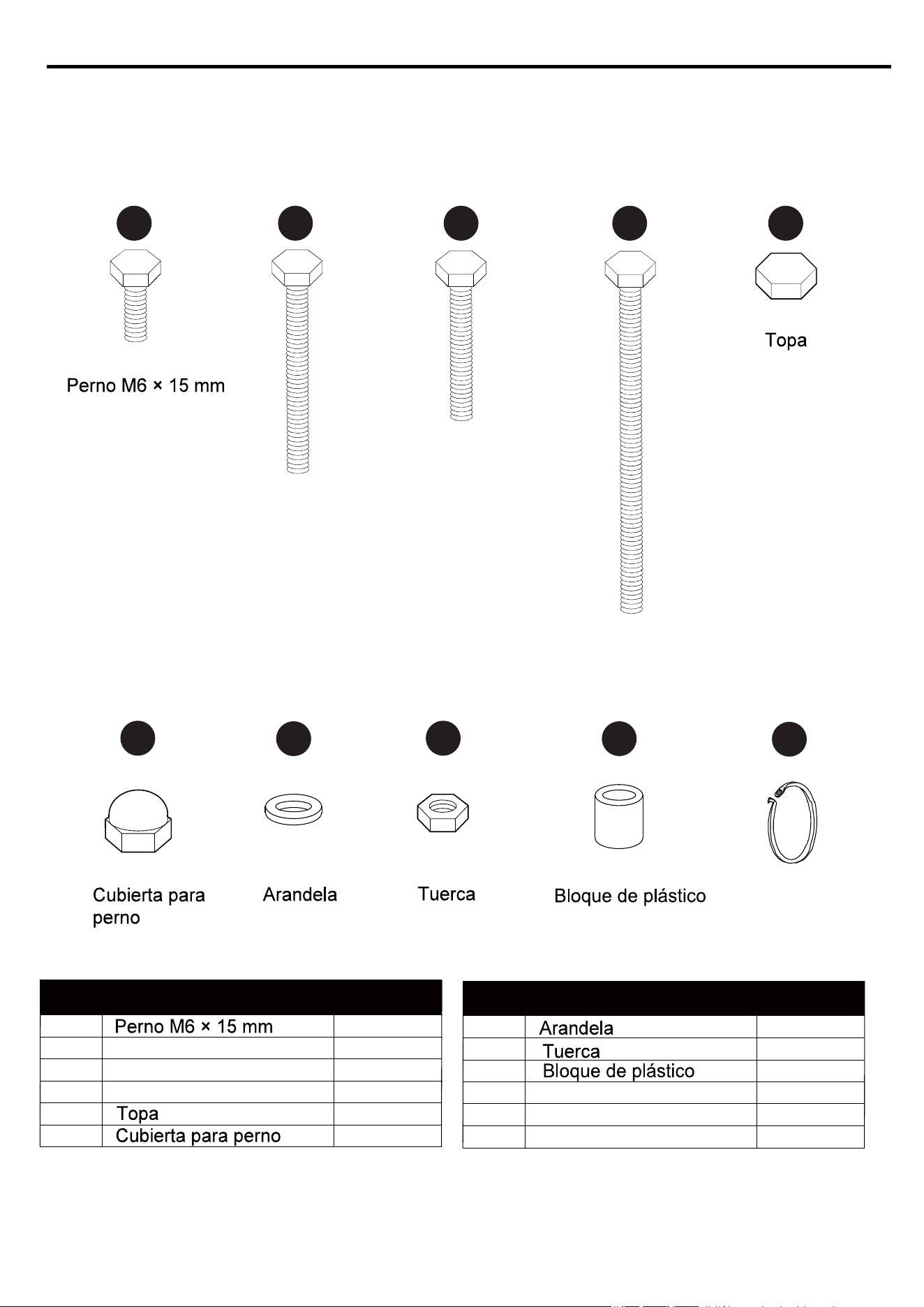
PIEZA DESCRIPCIÓN PIEZA #
AA
BB
CC
DD
EE
FF
Perno M6 × 43 mm
Perno M6 × 30 mm
Perno M6 × 83 mm
4
1
1
1
4
3
PIEZA DESCRIPCIÓN PIEZA #
GG
HH
KK
LL
Colgador
6
3
2
4
Colgador
AA CCBB DD EE
GG
HH
KK
LL
FF
Para obtener piezas de repuesto, llame a nuestro Departamento de Servicio al Cliente al
1-866-439-9800, de lunes a domingo de 8 a.m. a 8 p.m., hora estándar del Este. También puede
ponerse en contacto con nosotros en [email protected] o visitar www.lowespartsplus.com.
Perno M6 × 43 mm
Perno M6 × 30 mm
Perno M6 × 83 mm
