© 2020 AMETEK Electronic Systems Protection / Technical Support: 1-800-645-9721 / surgex.com / UM-UPS-Three-Phase-Rev-A
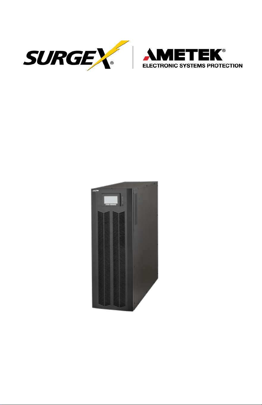
Uninterruptible Power Supply
Three-Phase User Manual
UPS-33020-02, UPS-33030-12, UPS-33040-12

Three-Phase User Manual
© 2020 AMETEK Electronic Systems Protection / Technical Support 1-800-645-9272 / surgex.com 1
TABLE OF CONTENTS
1.0 Safety and EMC Instructions 6
2.0 Installation 11
3.0 Operation 21
4.0 Troubleshooting 58
5.0 Storage and Maintenance 60
6.0 Specifications 62
Three-Phase User Manual
© 2020 AMETEK Electronic Systems Protection / Technical Support 1-800-645-9272 / surgex.com 2
IMPORTANT SAFETY INSTRUCTIONS
This
manual contains
important
instructions
to be followed
during
installation and
maintenance
of the UPS and
batteries.
Please
read all
instructions
before installing or
operating the
described equipment and PLEASE SAVE THIS MANUAL FOR
FUTURE REFERENCE!
SPECIAL SYMBOLS: The following are
examples
of symbols
used
on the UPS, or within this
manual
to alert you to important information.
Please
familiarize yourself with
these symbols.
Risk of Electric Shock—Observe the warnings
Associated
with the risk of electrical
shock.
CAUTION: HOT SURFACE—Do not touch! Risk of
burn
hazard.
CAUTION: REFER TO OPERATOR’S MANUAL
—Refer
to the operator’s
manual
for additional information, such
as
specific
operating
and/or
maintenance instructions.
Do Not Discard—This
equipment
utilizes
components
that contain lead and must be
disposed
of properly.
For
more information,
contact
your local
recycling/refuse or
hazardous waste center
.

Three-Phase User Manual
© 2020 AMETEK Electronic Systems Protection / Technical Support 1-800-645-9272 / surgex.com 3
Do Not Discard—Never discard Waste Electrical or
Electronic
Equipment
(WEEE) in the trash. For
proper
disposal contact
your local
recycling/refuse
or
hazardous
waste center.
Information of Special Note—Specific handling
or
operational instructions may apply.
Phase—This is the electrical symbol for the word
“phase”.
Recycle—Equipment or
components
are
made
of
recyclable material, please contact your local recycling
center
for proper
disposal.
Three-Phase User Manual
© 2020 AMETEK Electronic Systems Protection / Technical Support 1-800-645-9272 / surgex.com 4
NOTE TO USERS
To
ensure
correct
operation
of the UPS,
please
read this
instruction
manual
carefully.
Please
keep this
manual
handy for future
reference.
This UPS has dangerously high voltages on both its Input and
output connections. Contact with these voltages may be life
threatening. Please follow the operating instructions carefully.
Please give close attention to the warnings in this manual and
those posted on the UPS. There are no user serviceable parts
inside the UPS. Disassembly and/or maintenance should only be
done by authorized personnel.
IMPORTANT INFORMATION FOR USERS OF
THIS UNINTERRUPTIBLE POWER SUPPLY
1. Before
operating
the UPS or
connecting
any load
equipment,
please
ensure the UPS is connected to a properly grounded electrical supply.
2. This UPS has dangerously high voltages on both its input and output
connections. Contact
with
these voltages
may be life threatening.
3.
Please
do not
disassemble
the
covers.
There is a risk of
electric
shock.
4. In an
emergency,
immediately turn
off
the circuit
breaker
for
the
circuit supplying power to the UPS. Also immediately turn
off
the
battery circuit breaker.
5. This UPS has two power sources. One is the circuit supplying the UPS
with input power. The other is the UPS battery. Prior to any
maintenance,
both of
these
power
sources
must be
disconnected
to
ensure
that the UPS is
de-energized.
If
only the input
power
is
disconnected,
the UPS can still
operate
from the
battery, and
hazardous voltages
may still
exist.

Three-Phase User Manual
© 2020 AMETEK Electronic Systems Protection / Technical Support 1-800-645-9272 / surgex.com 5
6. To
prevent damage
or a safety
hazard,
keep the UPS away from
open flame and any other
devices
that may
cause sparks.
7. Do not open or
damage
individual battery
cases as
spillage of
caustic
electrolyte may occur resulting in
danger
to life, safety,
and
the
environment.
8. The
charging characteristics
of UPS
batteries
vary by both
brand
and type. For this
reason, replacement batteries
should be of
the
same
brand and type
as those specified
by the
manufacturer.
Using
batteries
other than the brand and type
specified
by
the
manufacturer
may affect the
performance
of the UPS.
Before
Installing
batteries
of different brand or type,
please
consult with
the
manufacturer.
9. The UPS has an internal EMI filter for
purposes
of
enhancing
electromagnetic compatibility with the input mains supply. This filter
produces leakage
current to earth on the input mains.
When selecting
a circuit
breaker
for the
branch
circuit supplying
power
to the UPS,
ensure
that the
breaker selected
is not an ELCB
type
circuit breaker that detects earth leakage current.
10.
Please contact
the
manufacturer
or an
authorized
distributor for
any
assistance with troubleshooting.
11. The UPS should only be
serviced
or
maintained
by a factory
authorized service technician.
12. This UPS
meets
FCC
Class
A
electromagnetic compatibility
requirements.
13.
Depleted batteries
must be
disposed
of in a proper
manner
.
Contact
your local recycling or
hazardous waste center
or the
UPS
manufacturer
for
instructions concerning
proper
disposal.
Three-Phase User Manual
© 2020 AMETEK Electronic Systems Protection / Technical Support 1-800-645-9272 / surgex.com 6
1.0 SAFETY AND EMC INSTRUCTIONS
All
safety
instructions
in this
document
must be read,
understood and
followed.
1.1 Transportation and Storage
CAU
TION
Please transport the UPS system only in the original packaging to protect against
shock and damage.
CAU
TION
The UPS must be stored in a room where the temperature is well regulated.
Ambient temperature should not exceed 40°C.
1.2 Preparation
CAU
TION
Condensation may form if the UPS system is moved immediately from a cold to a
warm environment. The UPS system must be completely dry before being
installed. Please allow at least two hours for the UPS system to acclimate to the
environment.
CAU
TION
Do not install the UPS system near water or in moist environments.
CAU
TION
Do not install the UPS system where it would be exposed to direct sunlight or
nearby heat source.
CAU
TION
Do not block ventilation holes on the UPS housing.
Three-Phase User Manual
© 2020 AMETEK Electronic Systems Protection / Technical Support 1-800-645-9272 / surgex.com 7
1.3 Installation
CAU
TION
Do not connect appliances or devices which would overload the UPS (e.g. big
motor-type equipment) to the UPS output terminal.
CAU
TION
Place cables in such a way that no one can step on or trip over them.
CAU
TION
Do not block air vents on the housing of the UPS. Ensure proper unit
spacing of ventilation.
CAU
TION
UPS comes equipped with grounding terminal, in the final installation phase,
connect grounding/earthing wire to the external UPS battery cabinets or
appropriate grounding terminals.
CAU
TION
The UPS can be installed only by qualified maintenance personnel.
CAU
TION
An appropriate disconnect device such as short-circuit backup protection should
be incorporated during installation.
CAU
TION
An integral emergency shutoff switch which prevents additional load from the UPS
in any mode of operation should be implemented during the installation.
CAU
TION
Secure the grounding/earthing wire before connecting to any live wire terminal
Three-Phase User Manual
© 2020 AMETEK Electronic Systems Protection / Technical Support 1-800-645-9272 / surgex.com 8
CAU
TION
Installation and wiring must be in accordance with the local electrical laws and
regulations.
1.4 Connection
W
ARN
ING
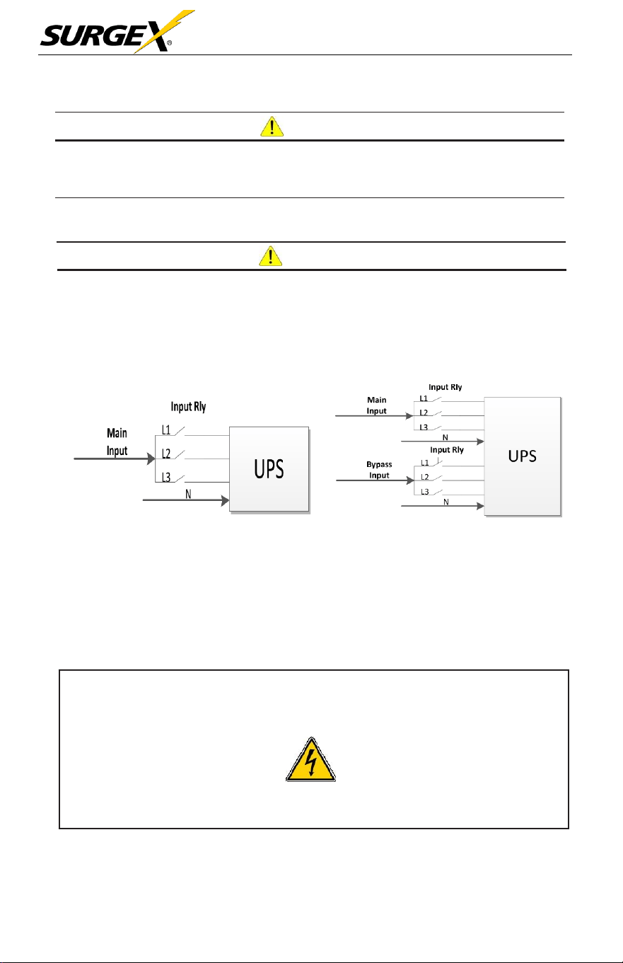
In accordance with safety standard, installation must include a Backfeed
Protection system, for example a contactor, which will prevent the appearance
of voltage or dangerous energy in the input mains during a mains fault. There is
no standard Backfeed Protection inside of the UPS. However, there are relays on
the Input to cut-off line voltage while the neutral is still connected to UPS.
Input Relay Diagram Input Relay Diagram for Dual-Input Model
•
There can be no derivation in the line that goes from the Backfeed Protection to the
UPS, as the standard safety would be infringed.
•
Warning labels should be placed on all primary power switches installed in places
away from the unit to alert the electrical maintenance personnel of the presence of
a UPS in the circuit. The label will bear the following or an equivalent text:
Before working on this
circuit
Isolate Uninterruptible Power Supply
(UPS)
Check for Hazardous Voltage between all terminals including the protected earth.
Risk of Voltage Backfeed!
Three-Phase User Manual
© 2020 AMETEK Electronic Systems Protection / Technical Support 1-800-645-9272 / surgex.com 9
• The power input for this unit must be three-phase rated in accordance
with the equipment nameplate. It also must be suitably grounded.
W
ARN
ING
:
HIGH
LEAKAGE
CURRENT!
EARTH CONNECTION IS ESSENTIAL BEFORE CONNECT SUPPLY VOLTAGE
• This UPS should be connected with a TN grounding/earthing system.
• Use of this equipment in a medical instrument or any life-sustaining equipment where
failure of this equipment can reasonably be expected to cause the failure of the life-
sustaining equipment, or significantly affect its safety or effectiveness, is not
recommended. Do not use this equipment in the presence of a flammable mixture with
air, oxygen or nitrous oxide.
• Connect grounding terminal of UPS to a grounding electrode conductor.
1.5 Operation
CAU
TION
Do not disconnect the grounding/earthing conductor cable on the UPS or the
building wiring terminals under any circumstance.
CAU
TION
The UPS system features its own internal current source (batteries). The
UPS output sockets or output terminal blocks may be electrically live even if the
UPS system is not connected to the building mains/live wires (standard models
only).
CAU
TION
In order to fully disconnect the UPS system, first press the “OFF” button and
then disconnect the mains/live wires.
CAU
TION
Ensure that no liquid or other foreign objects can enter into the UPS system.
CAU
TION
The UPS can be operated by any individual; no previous experience is
required.

Three-Phase User Manual
© 2020 AMETEK Electronic Systems Protection / Technical Support 1-800-645-9272 / surgex.com 10
1.6 Standards
* Safety
UL 1778, CSA C22.2 No.107.3-14
* EMI
Conducted Emission...............................: FCC Part 15, Subpart B
Class A
Radiated
Emission..................................:
FCC Part 15, Subpart B
Class A
NOTE:
This equipment has been tested and found to comply with the
limits for a Class A digital device, pursuant to part 15
of the FCC Rules. These limits are designed to provide reasonable
protection against harmful interference when the equipment is
operated in a commercial environment. This equipment generates,
uses, and can radiate radio frequency energy, and if not installed
and used in accordance with the instruction manual, may cause
harmful interference to radio communications. Operation of this
equipment in a residential area is likely to cause harmful
interference in which case the user will be required to correct the
interference at his own expense.

Three-Phase User Manual
© 2020 AMETEK Electronic Systems Protection / Technical Support 1-800-645-9272 / surgex.com 11
2.0 INSTALLATION
We offer optional parallel function upon
request.
The UPS with
parallel
function is called the “Parallel Model”. We have
detailed
installation
and
operation procedures
of the Parallel Model in the following
chapter
.
2.1 Unpacking and Inspection
Unpack the package and check the package contents. The shipping package
should contain:
•
One UPS
•
One User Manual
NOTE:
Before the installation, please inspect the unit for any physical
damage and for all parts and accessories. If damage is found or
parts/accessories are missing, do not turn on the unit and notify the
carrier and SurgeX immediately. Please keep the original packaging
for future use. It is recommended to keep each equipment and
battery set in their original packaging because they have been
designed to provide maximum protection during transportation and
storage
2.2 UPS Floor Anchoring
NOTE:
The
L-shaped
floor
anchoring brackets
that
secured the
enclosure to the pallet during shipment may be used for a stand-
alone
UPS
enclosure to enhance stability.
Three-Phase User Manual
© 2020 AMETEK Electronic Systems Protection / Technical Support 1-800-645-9272 / surgex.com 12
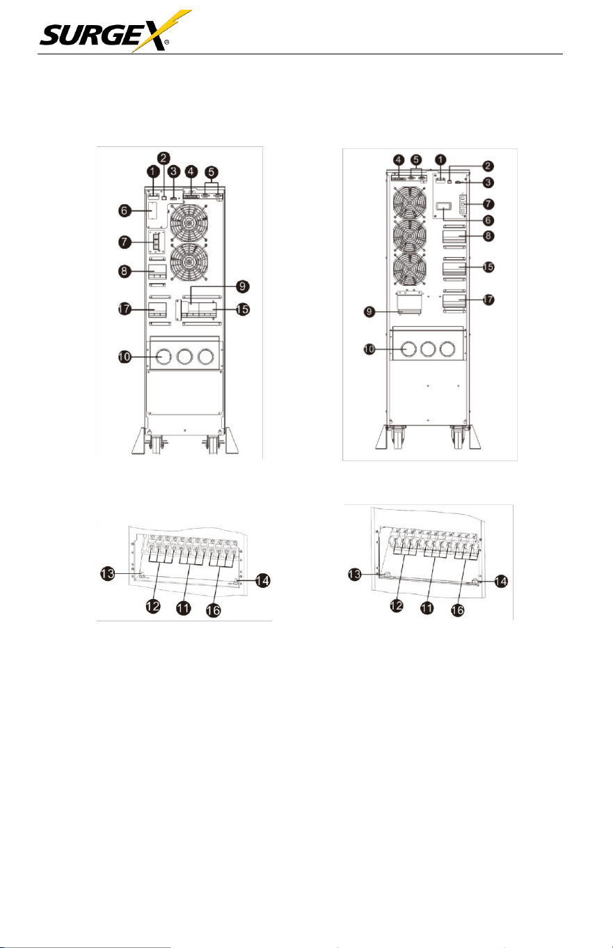
2.3 Wiring Terminal View
Diagram 1: 10kVA Rear Panel Diagram 2: 15kVA/20kVA Rear
Panel
Diagram 3: 10kVA Input/Output Terminal Diagram 4: 15K/20kVA Input/Output
Terminal
Three-Phase User Manual
© 2020 AMETEK Electronic Systems Protection / Technical Support 1-800-645-9272 / surgex.com 13
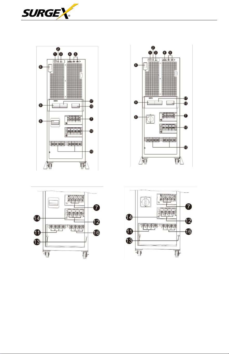
Diagram 5: 30kVA Front view with door open Diagram 6: 40kVA Front view with door open
Diagram 7: 30kVA Input /Output Terminal Diagram 8: 40kVA Input/Output
Terminal

Three-Phase User Manual
© 2020 AMETEK Electronic Systems Protection / Technical Support 1-800-645-9272 / surgex.com 14
1.
RS-232 communication
port (only for firmware
updates)
2. USB communication port
3.
Emergency
power
off
function
connector
(EPO
connector)
NOTE:
Keep the
EPO
connector closed for UPS
normal operation. To activate
EPO
function,
please remove the jumper.
4.
Share
current port (only
available
for parallel
model)
5. Parallel port (only
available
for parallel
model)
6. Intelligent
slot
7. External battery
connector
(Only
available
for long-run
model)
8. Line input circuit breaker/switch
9. Maintenance bypass switch
10.
Input/Output
terminal (Refer to
diagram
3 for the
details)
11. Line input terminal
12. Output terminal
13. Input
grounding terminal
14. Output grounding terminal
15. Bypass input circuit breaker/switch
16. Bypass input terminal
17. Output circuit breaker
Three-Phase User Manual
© 2020 AMETEK Electronic Systems Protection / Technical Support 1-800-645-9272 / surgex.com 15
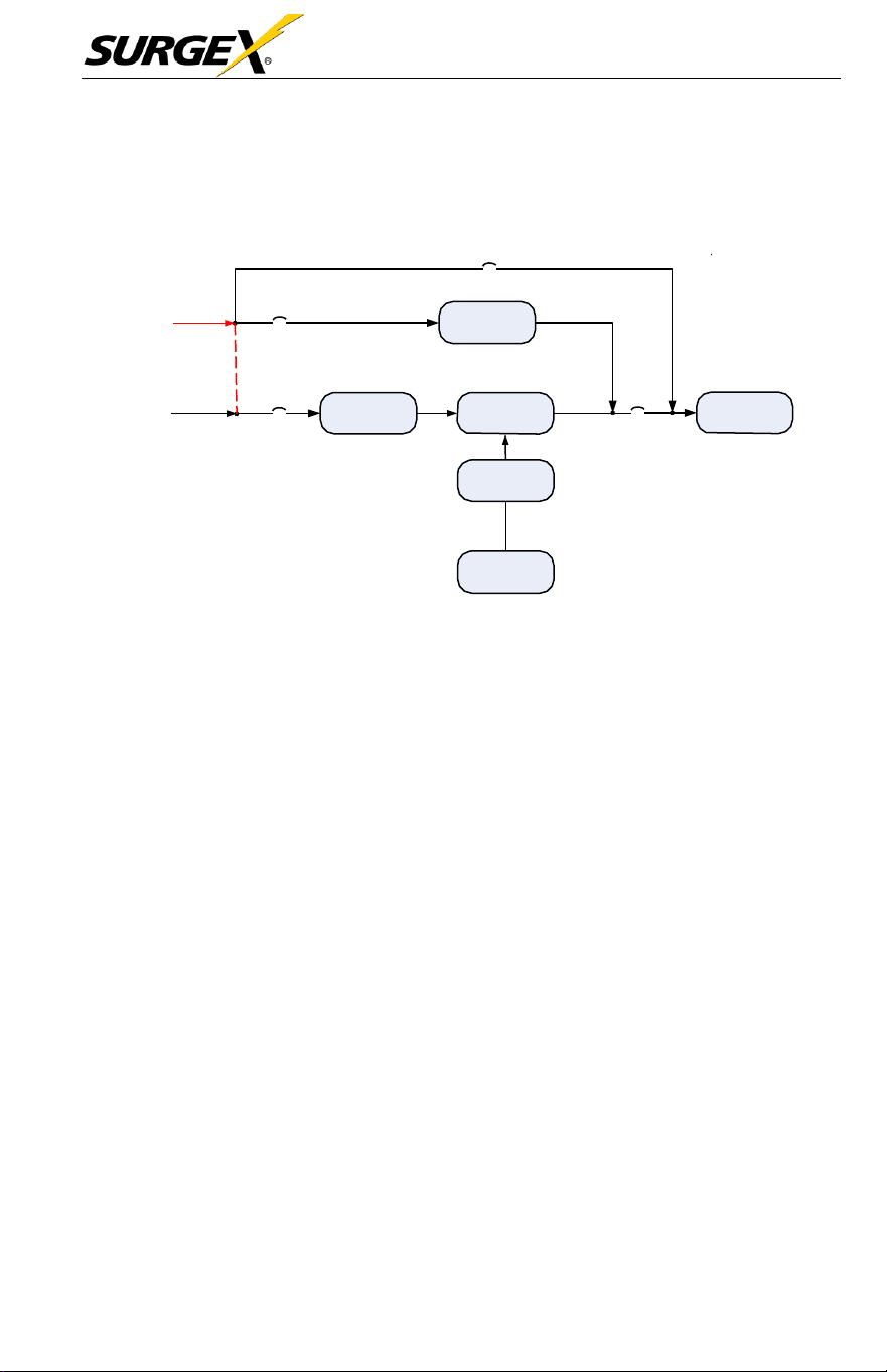
2.4 Operation Principle
Maintain
Breaker
Customer AC
Supply
Bypass
Breaker
Bypass
(Remove tie if
dual source)
Customer AC
Supply
Input Breaker
PFC
(AC/DC)
Inverter
(DC/AC)
Output
Breaker
Critical Load
DC/DC
Battery
The Operating Principle of the
UPS
2.5 Single UPS Installation
Installation and wiring must be carried out in
accordance
with the local
electric laws and
regulations
by trained
professionals.
1. Make sure that the mains wire and
breakers
of the building
are
rated
for
the
capacity
of the UPS to
prevent
electric shock or risk of fire.
See
Facility Data
Planning
Guide on
page
47 for
guidance.
2. Switch
off
the mains switch in the building before
installation.
3. Turn
off
all
connected devices
before
connecting
to the
UPS
4.
Remove
the terminal block cover at the rear panel of
UPS.
Then
connect
the wires
according
to the following terminal block
diagrams.
(Connect
the
grounding/earthing
wire first when making other wire
connections. Remove the grounding/earthing wire last when connecting the
UPS!)
Three-Phase User Manual
© 2020 AMETEK Electronic Systems Protection / Technical Support 1-800-645-9272 / surgex.com 16
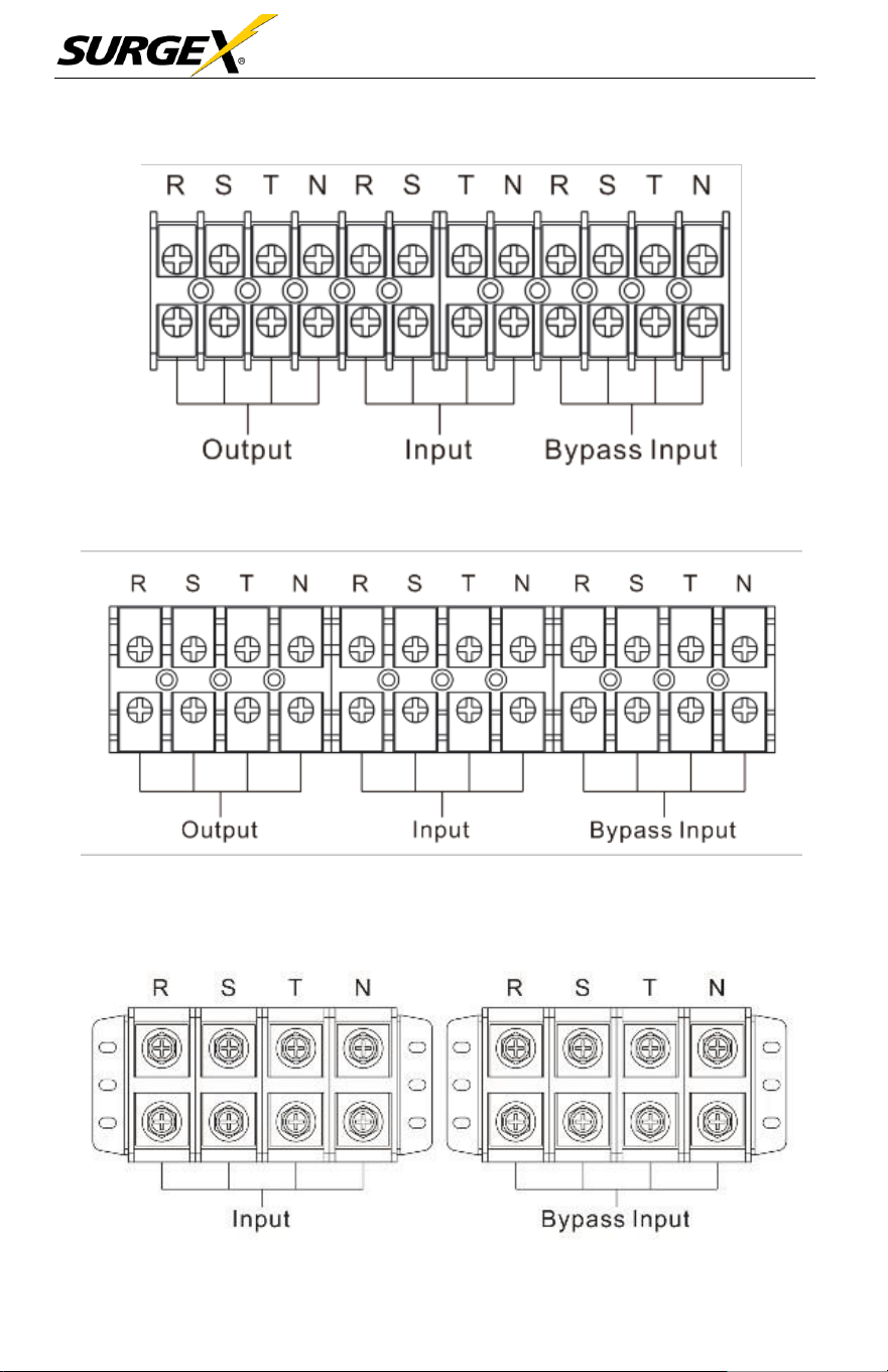
Terminal Block Wiring Diagram for
10kVA
Terminal Block Wiring Diagram for 15 / 20
KVA
Three-Phase User Manual
© 2020 AMETEK Electronic Systems Protection / Technical Support 1-800-645-9272 / surgex.com 17
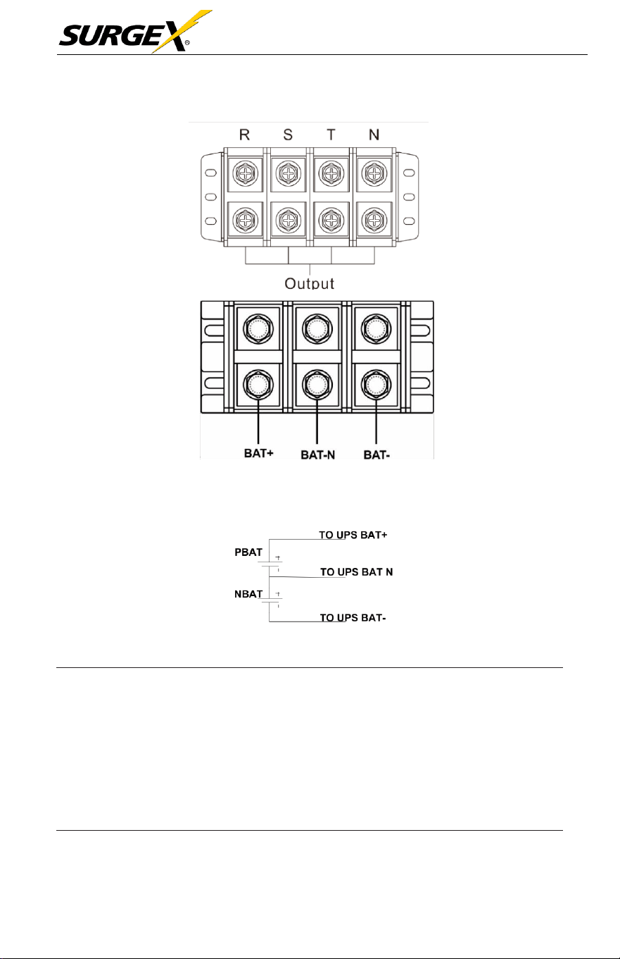
Terminal Block Wiring Diagram for 30 / 40
KVA
Battery Connection Wiring
NOTE 1: Make sure that the wires are connected securely with the
terminals.
NOTE 2: Please install the output breaker between the output terminal
and the load. The breaker should have leakage current
protective function if necessary.
5. Put the terminal block cover back at the rear panel of the
UPS.

Three-Phase User Manual
© 2020 AMETEK Electronic Systems Protection / Technical Support 1-800-645-9272 / surgex.com 18
W
ARN
I
N
G
(
S
ta
nd
ar
d
M
od
e
l Onl
y)
•
Make sure the UPS is off before the installation. The UPS should not be turned
on during wiring connection.
•
Do not attempt to modify the standard model into the long-run model.
In particular, do not try to connect the standard internal battery to the
external battery. The battery type and voltage may be different, risk of
electric shock or fire may occur!
W
ARN
I
N
G
(
Long
R
un
M
od
e
l Onl
y)
•
Make sure a DC breaker or other protective device between UPS and the
external battery pack is installed for added safety. If not, please install it
carefully. Switch off the battery breaker before installation.
NOTE: Set the battery pack breaker in “OFF” position and then install the
battery pack.
•
Pay special attention to the rated battery voltage marked on the rear panel. If
you want to change the numbers of the battery in a chain, make sure you
modify the UPS setting accordingly. Connection with wrong battery voltage
may cause irreversible damage of the UPS.
•
Pay special attention to the polarity marking on external battery terminal
block. Connection with wrong battery voltage may cause irreversible
damage of the UPS.
•
Make sure the protective grounding/earthing wiring is adequate. The current
spec, color, position, connection and conductance reliability of the wire
should be verified.
•
Make sure the utility input and output wiring are rated correctly. The
current spec, color, position, connection and conductance reliability of the
wire should be verified. Make sure the L/N side is correct, not reverse or
short-circuited.
Three-Phase User Manual
© 2020 AMETEK Electronic Systems Protection / Technical Support 1-800-645-9272 / surgex.com 19
2.6 UPS Installation for Parallel System
If
the UPS is only for single
operation,
you may skip this
section.
1. Install and wire the UPS
according
to the
section 2-5.
2.
Connect
the output wires of
each
UPS to an output
breaker
.
3.
Connect
all output
breakers
to a
centralize breaker.
This
centralize
output breaker will then connect directly to the loads.
4. Either
common
battery
packs
or
independent
battery
packs
for
each UPS are allowed.
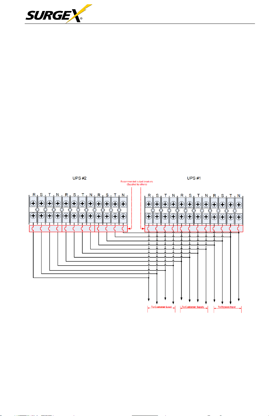
5. Refer to the following wiring
diagram
for input, output and
bypass
input:
Wiring Diagram of Parallel System for 10 / 15 / 20
kVA
Three-Phase User Manual
© 2020 AMETEK Electronic Systems Protection / Technical Support 1-800-645-9272 / surgex.com 20
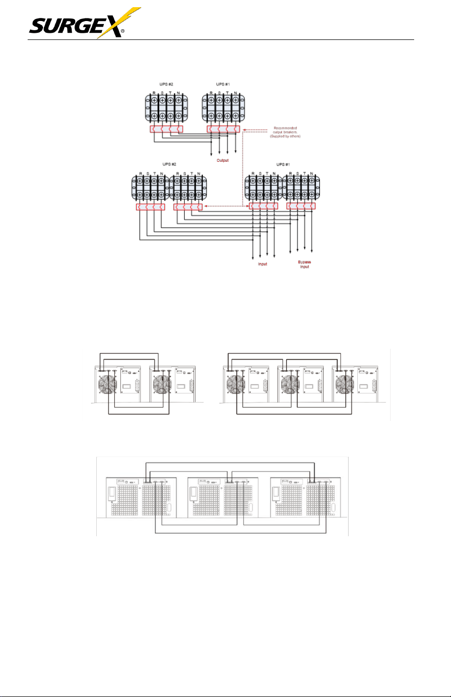
Wiring Diagram of Parallel System for 30 / 40
kVA
6. Refer to the following
communication
wiring
diagrams
for
shared
Current cable and parallel cable connections.
Diagram 1: Two UPSs in Parallel Diagram 2: Three UPS in
Parallel
Parallel System for 10 / 15 / 20 kVA
Diagram 1: Two UPSs in Parallel Diagram 2: Three UPS in
Parallel
Parallel System for 30 / 40 kVA
2.7 Software Installation
For optimal
computer system protection,
install UPS monitoring
software
to
configure UPS
shutdown operation.
Three-Phase User Manual
© 2020 AMETEK Electronic Systems Protection / Technical Support 1-800-645-9272 / surgex.com 21
3.0 OPERATION
3.1 Initial Operation
1. Before
operation,
make sure that the two strings of
batteries
are
connected
correctly in order of ”+, GND, -” terminals and
the
breaker
of the battery pack is at
“ON”
position (Long-run
model
only).
2. Press the “
”
button to set up the power supply for
the
UPS.
UPS
will
enter to power on mode. After initialization, UPS will enter to
“No Output mode”.
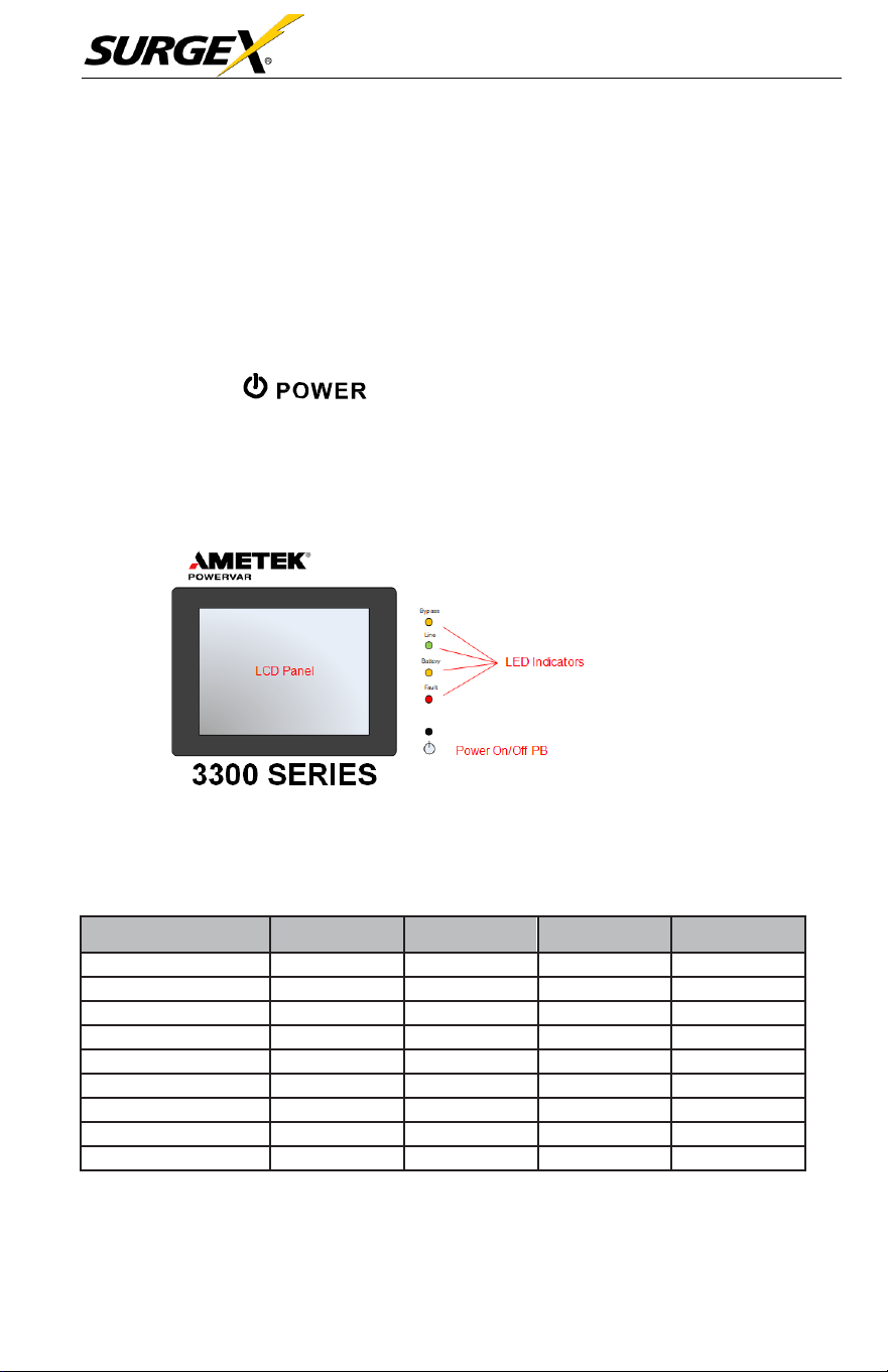
3.2 LED Indicators and LCD Panel
LED Indicators
4 LEDs on the front panel show the UPS working
status:
LED
Mode
Bypass
Line
Battery
Fault
UPS On
●
●
●
●
Standby mode
○
○
○
○
Bypass mode
●
○
○
○
Line mode
○
●
○
○
Battery mode
○
○
●
○
CVCF mode
○
●
○
○
Battery Test
●
●
●
○
ECO mode
●
●
○
○
Fault
○
○
○
●
Note: ●
means
LED is lighting, and
○
means
LED is
faded.
Three-Phase User Manual
© 2020 AMETEK Electronic Systems Protection / Technical Support 1-800-645-9272 / surgex.com 22
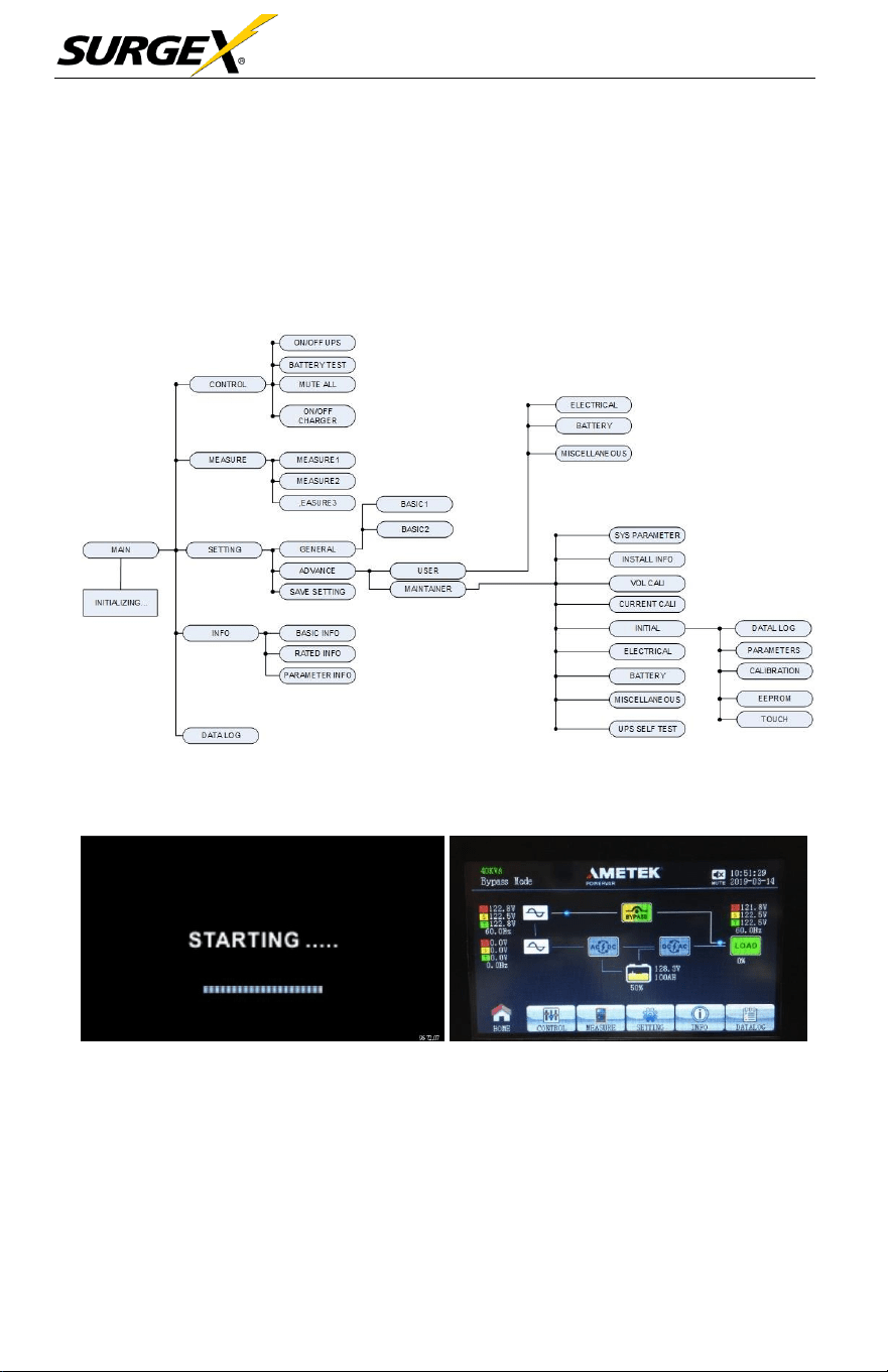
3.3 Screen Description
After initialization, the LCD
will
display the main
screen.
There are five
sub-
menus:
control,
measure,
setting, information, and data log. Touch any
sub-
menu
icon to enter the
sub-screen.
3.3.1 Main screen
Upon powering on, the LCD
will
start initialization approximately few
seconds as shown below.
After initialization, the main
screen
will
display
as
shown below. On
the
bottom, there are five icons to
represent
five
sub-menus: CONTROL,
MEASURE, SETTING, INFO, DATALOG.
Three-Phase User Manual
© 2020 AMETEK Electronic Systems Protection / Technical Support 1-800-645-9272 / surgex.com 23
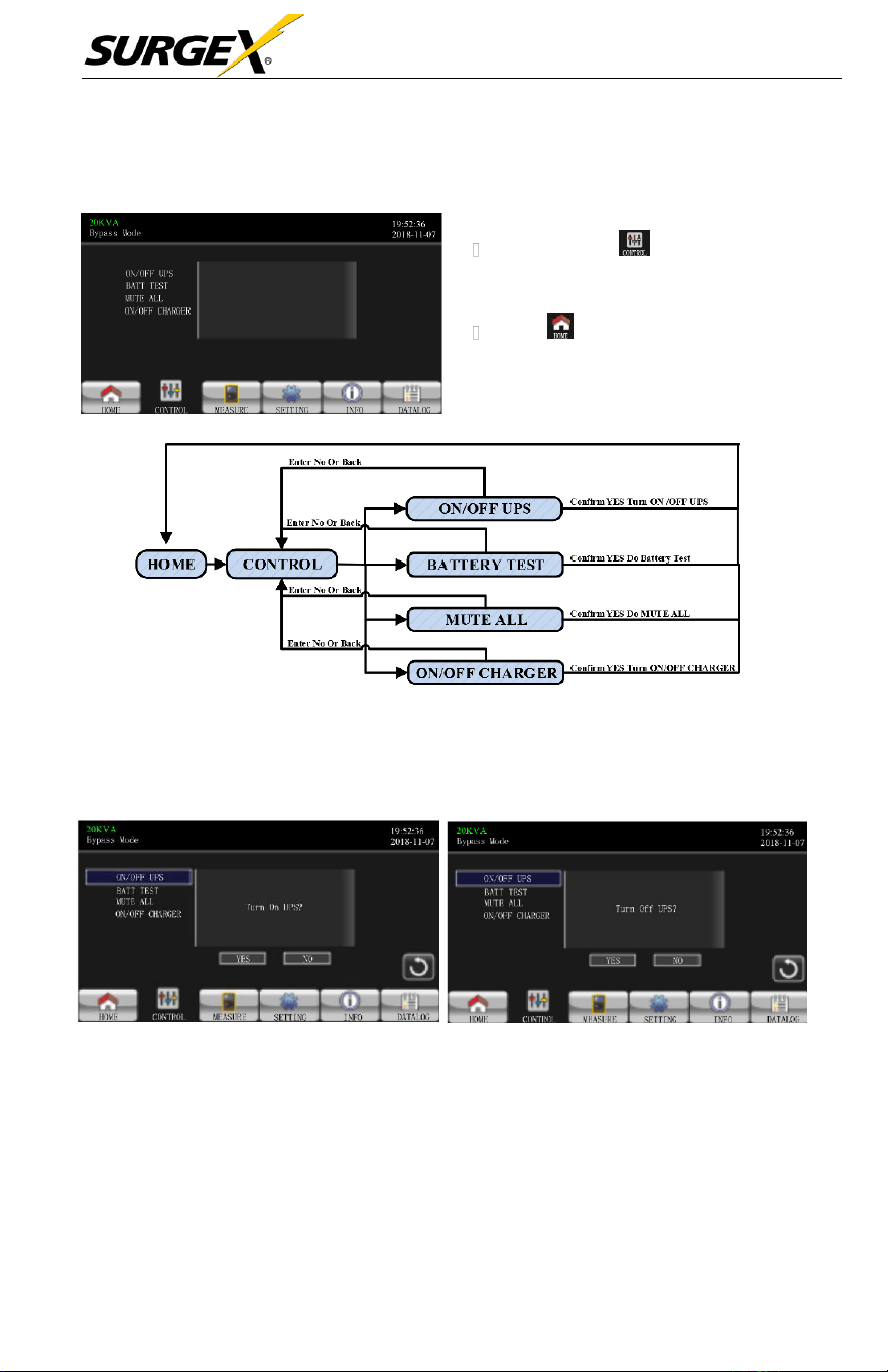
3.3.2 Control screen
MENU TREE
• Touch the icon to enter control
sub-menu.
• Touch icon to return back to
main screen from any screen.
Screen 1.0 «Control» and its Sub-Menus
h
On/Off UPS
TURN ON UPS
TURN OFF UPS
•
It
will show Turn on UPS? when UPS is off.
•
It
will show Turn off UPS? when UPS is on.
•
Touch YES to turn the UPS on or off. The
screen
will
return to the
main
screen.
•
Touch Back to return to main screen immediately or NO to cancel this
operation and go back to the main screen.
Three-Phase User Manual
© 2020 AMETEK Electronic Systems Protection / Technical Support 1-800-645-9272 / surgex.com 24
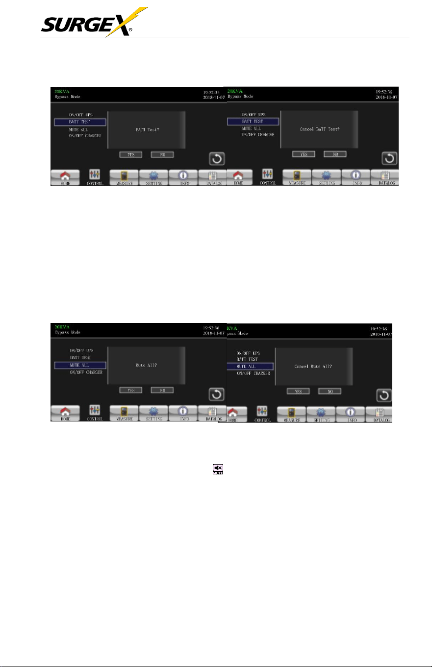
➢
Battery Test
Battery Test
Cancel Battery
T
est
•
The
unit
will
display “Battery Test”
if
the UPS is not in test mode. T
ouch
Yes
to start the battery test. “Battery testing…” will appear during the battery test
period. After a few
seconds,
the battery test result
will
show
on the screen.
Touch Back to return to main screen immediately or No to
cancel
this
operation
and return to the main
screen.
“Cancel battery test”
will
appear
if
in test
mode.
➢
Audio Mute
Mute All
Cancel Mute
All
• The
unit
will
display “Mute all”
if
the audio is active. Touch Yes to activate
mute.
If
“Mute all” is active, the icon on the top left corner of the
main
screen will appear. Touch Back to return to the CONTROL
screen
immediately
or No to
cancel
this
operation
and return to the CONTROL
screen.
• The
unit
will
display “Cancel mute”
if
the UPS is
already
mute. T
ouch
Yes
activate
audio function or No to keep mute. Touch Back to return to CONTRL
screen.
Three-Phase User Manual
© 2020 AMETEK Electronic Systems Protection / Technical Support 1-800-645-9272 / surgex.com 25
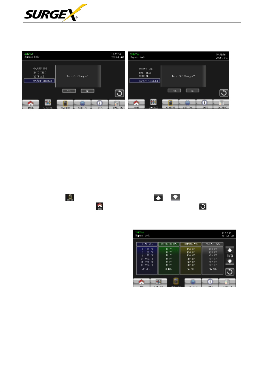
➢
On/Off Charger
TURN ON CHARGER
TURN OFF CHARGER
• The
unit will display “Turn on Charger?” when the
charger
is off.
• The
unit will display “Turn off Charger?” when the charger is on.
• Touch Yes to turn the
charger
on or off. The
screen
will
return to the
main
screen.
• Touch Back to return to the CONTROL
screen
immediately or No to
cancel
this
operation
and return to CONTROL
screen.
3.3.3 Measure Screen
• Touch the to enter measure page. Touch the or to browse
information. Touch the to return to main screen. Touch the icon to go
back to previous menu.
• LINE VOL: The real time value
of R, S and T
phase voltage,
RS,
ST, TR voltage and input
frequency.
•
INVERTER VOL: The real
time value of R, S and T
inverter voltage, RS, ST and
TR voltage and
frequency.
•
BYPASS VOL: The real time
value of R, S and T bypass
voltage, RS, ST and TR voltage
and frequency.
•
OUTPUT VOL: The real time
value of R, S T output voltage,
RS, ST and TR voltage and
frequency,
Measure Screen Page 1
Three-Phase User Manual
© 2020 AMETEK Electronic Systems Protection / Technical Support 1-800-645-9272 / surgex.com 26
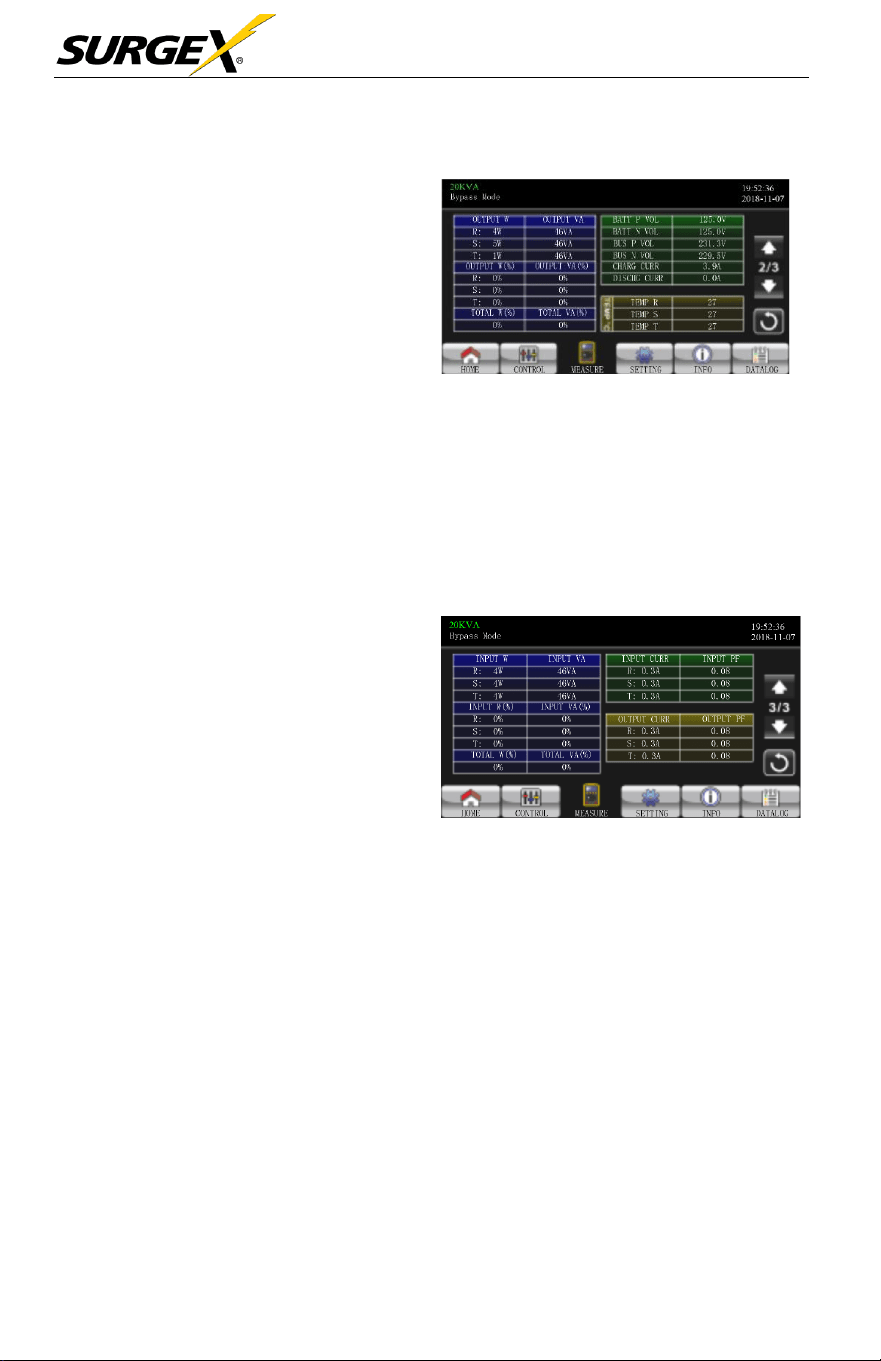
•
OUTPUT
W: R, S and T output
power in watt.
•
OUTPUT
VA: R, S and T output
power in VA.
•
OUTPUT
W (%): R, S and
T output power watt in
percentage.
•
OUTPUT
VA (%): R, S
and T output power VA in
percentage.
Measure Screen Page 2
• Total watt and VA: Total output load in watt and VA.
• BATT Voltage/Bus Voltage/Charging Current/Discharging Current:
The real time value of DC
related
information
.
•
T
emperature:
Temperature
of R, S and T
phases.
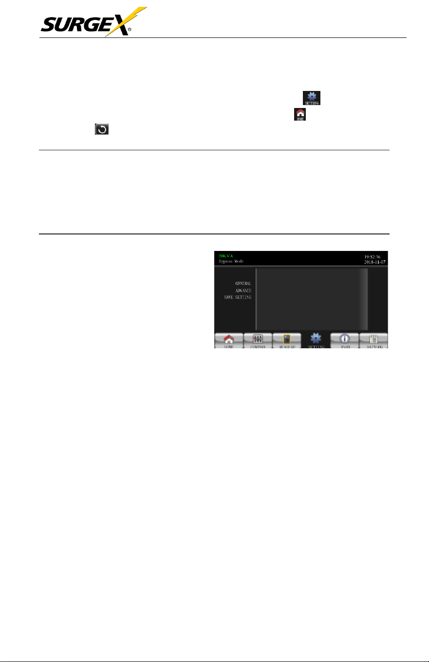
• INPUT W: R, S and T input
power in watt.
• INPUT VA: R, S and T input
power in VA.
• INPUT W (%): R, S and
T input power watt in
percentage
• INPUT VA (%): R, S and T
input power VA in percentage.
Measure Screen Page 3
• Input current: The real-time value of input current in R, S and T phases.
•
Output
current: The real-time value of output current in R, S and T
phases.
Three-Phase User Manual
© 2020 AMETEK Electronic Systems Protection / Technical Support 1-800-645-9272 / surgex.com 27
3.3.4 Setting screen
This
sub-menu
is
used
to set the
parameters
of the UPS. Touch to enter setting
menu page. There are 2 options: Basic and Advanced. Touch the to return to main
screen. Touch to go back to previous menu.
NOTE:
Not all settings are available in every operation mode. If the setting
is not available in present mode, the LCD will keep its original setting
parameter showed instead of changing the parameters.
•
GENERAL: It is to set
up basic
information of the
UPS.
It’
s
not
related
to any function
parameter.
•
ADVANCE: It is
required to
enter
password to access to the
“ADVANCE”
setting. There
are
two types of authority, User
and
Maintainer.
Setting Screen
• SAVE SETTING:
Select
this function
save
the
setting(s)
when it is
done.
Click this tap to
execute
saving function no matter
if
UPS is
connected to
battery or not. However,
it’
s
requested
to shut down the UPS to
complete
setting changes.
Three-Phase User Manual
© 2020 AMETEK Electronic Systems Protection / Technical Support 1-800-645-9272 / surgex.com 28
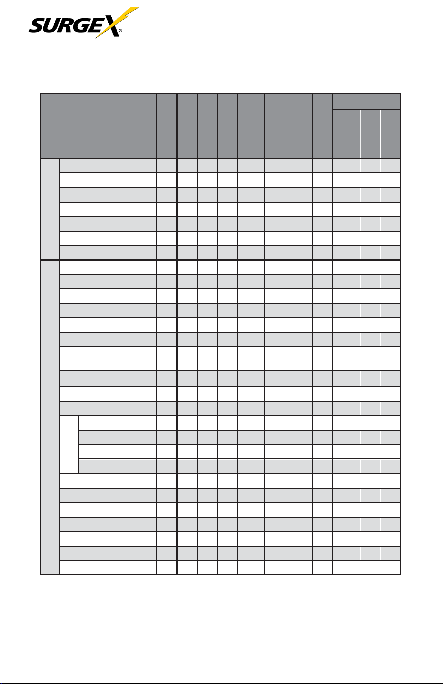
The Authority List:
UPS OPERA
TION
MODE
SETTING
ITEM
Standby Mode
Bypass Mode
Line Mode
Battery Mode
Battery
T
est
Mode
Fault Mode
Converter
Mode
ECO Mode
Authorization
No
Password
User
Maintainer
GENERAL
Date/Time
Y
Y
Y
Y
Y
Y
Y
Y
Y
Language
Y
Y
Y
Y
Y
Y
Y
Y
Y
Input
Source
Y
Y
Y
Contact
Y
Y
Y
Y
Y
Y
Y
Y
Y
Phone
Y
Y
Y
Y
Y
Y
Y
Y
Y
Mail
Y
Y
Y
Y
Y
Y
Y
Y
Y
Audio Alarm
Y
Y
Y
Y
Y
Y
Y
Y
Y
ADVANCE
Output Voltage
Y
Y
Y
Y
Output
Frequency
Y
Y
Y
Y
CVCF Mode
Y
Y
Y
Y
Bypass Forbid
Y
Y
Y
Y
Y
Y
Y
Y
Y
Bypass Mode
Y
Y
Y
Y
Y
Y
Y
Y
Y
Bypass Voltage Range
Y
Y
Y
Y
Bypass Frequency
Range
Y
Y
Y
Y
ECO Mode
Y
Y
Y
Y
ECO Voltage
Range
Y
Y
Y
Y
ECO
Frequency Range
Y
Y
Y
Y
Battery
Warning Voltage
Y
Y
Y
Y
Y
Y
Y
Y
Y
Shutdown Voltage
Y
Y
Y
Y
Y
Y
Y
Y
Y
Age Alert
Y
Y
Y
Y
Y
Y
Y
Y
Y
Capacity
in Ah
Y
Y
Y
Y
Y
Y
Y
Y
Y
Auto Restarts
Y
Y
Y
Y
Y
Y
Y
Y
Y
Y
System Shutdown Time
Y
Y
Y
Y
Y
Y
Y
Y
Y
Y
System Restore Time
Y
Y
Y
Y
Y
Y
Y
Y
Y
Y
Password Setting
Y
Y
Y
Y
Y
Y
Y
Y
Y
Y
Default User
Password
Y
Y
Y
Y
Y
Y
Y
Y
Y
Model Name
Y
Y
Y
Y
Y
Y
Y
Y
Y
Serial Number
Y
Y
Y
Y
Y
Y
Y
Y
Y
Three-Phase User Manual
© 2020 AMETEK Electronic Systems Protection / Technical Support 1-800-645-9272 / surgex.com 29
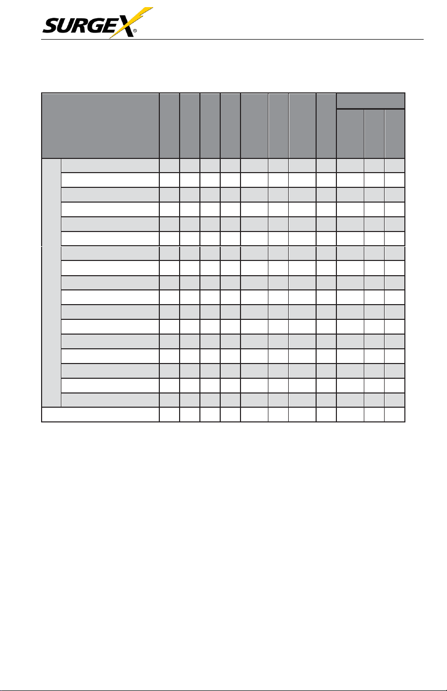
UPS OPERA
TION
MODE
SETTING
ITEM
Standby Mode
Bypass Mode
Line Mode
Battery Mode
Battery
T
est
Mode
Fault Mode
Converter
Mode
ECO Mode
• Auth
oriza
tion
No
Password
User
Maintainer
ADVANCE
Manufacturers
Y
Y
Y
Y
Y
Y
Y
Y
Y
Max.
Charging Current
Y
Y
Y
Y
Y
Y
Y
Y
Battery Numbers
Y
Y
Y
Y
Y
Y
Y
Y
Charge
V
oltage
Y
Y
Y
Y
Y
Y
Y
Y
Charger Numbers
Y
Y
Y
Y
Y
Y
Y
Y
Float
V
oltage
Y
Y
Y
Y
Y
Y
Y
Y
UPS Type
Y
System
Install
Date
Y
Y
Y
Y
Y
Y
Y
Y
Y
Battery Install
Date
Y
Y
Y
Y
Y
Y
Y
Y
Y
Voltage Calibration
Y
Y
Y
Current Calibration
Y
Y
Y
Y
Clean Data Log
Y
Y
Y
Y
Y
Y
Y
Y
Y
Reset Parameters
Y
Y
Y
Reset
Calibration
Y
Y
Y
Reset EEPROM
Y
Y
Y
Touch Calibration
Y
Y
Y
Y
Y
Y
Y
Y
Y
UPS
Self Test
Y
Y
Save Setting
Y
Y
Y
Y
Y
“Y” means that this setting item can be set in this operation mode.
Three-Phase User Manual
© 2020 AMETEK Electronic Systems Protection / Technical Support 1-800-645-9272 / surgex.com 30
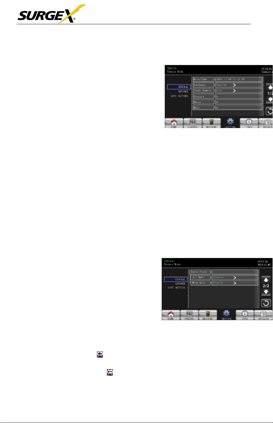
GENERAL
•
Date/Time: Set the date and
time. The format is
YYYY-MM-
DD HH:MM:SS.
The calendar
day will be automatically
changed when the year, month
and date are set.
•
Language: Set the LCD
language. Only available
in English.
General Screen Page 1
•
Input Source: Select the input source. There are two options: Line (utility)
and generator. Line is default setting. This setting value will show on the main
page. When “generator” is
selected,
the
acceptable
input
frequency
will
be
fixed at the
range
of
40~75Hz.
This setting value will show on the status bar.
•
Service Contact: Set the
name
of
contact person
and the maximum
length is 18 characters.
•
Service Phone: Set the
service phone number.
Only 0~9, + and –
are
accepted.
The maximum length is 14
characters.
•
Service Mail: Set the
service
email
accounts
up to two and the maximum
length is 36 characters.
➢ Audio Alarm: There are two events
available to mute. You may choose
Enable or Disable alarm when related
events occur.
Enable: When selected, alarm will
be mute when related events occur.
Disable: When selected, UPS will
alarm when related events occur.
General Screen Page 2
• All
Mute: When “enable” is
selected,
all the faults and
warnings
will
be
mute. It
will
show on the top right corner of the main
screen.
• Mode Mute: UPS status
mode alarm enable
/disable.
If
“Mode Mute”
is
activated, it will show on the top right corner of the main
screen.
Three-Phase User Manual
© 2020 AMETEK Electronic Systems Protection / Technical Support 1-800-645-9272 / surgex.com 31
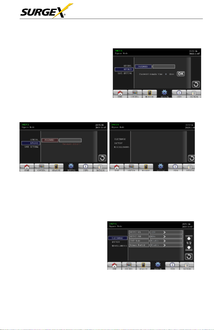
ADVANCE
A (4) digit
password
is
required to
access
to the
“ADVANCE”
page.
•
ADVANCE > User
- To access to the “Advance >
User” Setting menu page, the
default
password
is “0000”.
-
If
entered password
is
correct,
the page will jump to the setting
screen.
Advance Password Page
-
If
the
password
is not
correct,
the user
will
be
asked
to enter
again.
Password Error Page Advance Setting Menu Page
There are three sub-menus under “Advance > User” setting:
ELECTRONIC, BATTERY
and MISCELLANEOUS.
ELECTRICAL
•
Output Voltage: Select the
output rated voltage.
There are two options, 120V
and
127V. 120Vac is the
default
setting.
•
Output Frequency: Select
output rated
frequency
.
50Hz: The output
frequency is
setting for
50Hz.
Electrical Setting Page 1
60Hz: The output
frequency
is setting for
60Hz.
Three-Phase User Manual
© 2020 AMETEK Electronic Systems Protection / Technical Support 1-800-645-9272 / surgex.com 32
➢ CVCF Mode (constant voltage and constant frequency function)
•
Enable: CVCF function is
enabled.
The output
frequency
will
be fixed
At 50Hz or 60Hz
according
to setting of “OP Freq.”. The input
frequency
can
range
from 40Hz to
70Hz.
•
Disable: CVCF function is
disabled.
The output
frequency
will
synchronize
with the
bypass frequency
within 45~55 Hz for
50Hz
system
or within 55~65 Hz for 60Hz
system.
Disable is
the
default
setting.
➢ Bypass Forbid:
•
Enable:
Bypass
forbid is
enabled.
When
selected,
running in
Bypass
mode is not allowed under any situations.
•
Disable:
Bypass
forbid is
disabled.
When
selected,
UPS
will
run in
Bypass
mode
depending
on “Bypass at UPS
off”
setting. It is
the
default
setting.
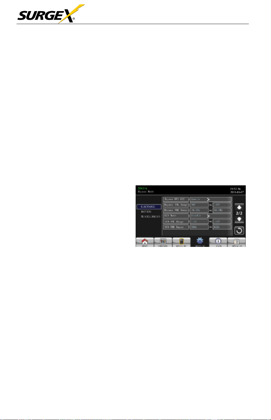
➢ Bypass at UPS off: Select the
bypass status when manually
turning
off
the UPS. This
setting
is only available when
“Bypass forbid.” is set to
“Disable”.
•
Enable: When
selected, bypass mode is
activated.
Electrical Setting Page 2
•
Disable: When selected, bypass is disabled and no output through
bypass
will
occur when manually turning
off
the
UPS.
•
Bypass Voltage Range: Set the bypass voltage range.
•
L: Low voltage point for
bypass.
The setting
range
is 96V ~ 110V. 96V
is default
setting.
•
H: High voltage point for
bypass.
The setting
range
is 130V ~ 146V
.
146V is default
setting.
➢ Bypass FRE Range: Set the
bypass frequency range. The
acceptable
bypass frequency ranges
from 46Hz to 54Hz when the UPS is a
50Hz
system
and from 56Hz to 64Hz when UPS is a 60Hz
system.
➢ ECO mode:
Enable/Disable
ECO mode. Default setting is “Disab
le”.
Three-Phase User Manual
© 2020 AMETEK Electronic Systems Protection / Technical Support 1-800-645-9272 / surgex.com 33
➢ ECO Voltage Range: Set the ECO voltage
range
.
•
L: Low voltage point for ECO mode. The setting
ranges
from “rated
output voltage – 5V” to “Rated output voltage – 11V”. “Rated
output
voltage – 5V” is default
setting.
•
H: High voltage point for ECO mode. The setting
range
is from
“Rated
output voltage + 5V” to “Rated output voltage + 11V”. “Rated
output
voltage + 5V” is default
setting.
➢ ECO FRE Range: Set the ECO
frequency range.
The setting
ranges from
46Hz to 54Hz when the UPS is a 50Hz
system
and from 56Hz to
64Hz
when
the UPS is a 60Hz
system.
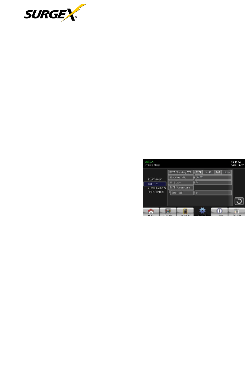
BATTERY
➢ Battery Warning Voltage:
Battery Setting Page
•
HIGH: High battery warning voltage.
The setting rang is 14.0V ~ 15.0V.
14.4V
is
default
setting.
•
LOW: Low battery warning voltage.
The setting range is 10.1V ~ 14.0V.
1
1.4V is default setting. This
parameter setting is related to the “Shutdown Voltage” setting. This setting value
should be higher than “Shutdown Voltage” setting.
➢ Shutdown Voltage:
If
battery voltage is lower than this point while in
battery
mode, the UPS
will
automatically
shut down. The setting
range
is 10.0V
~
12.0V. 10.7V is default setting (The setting is only
available
for long-run
model).
Battery Parameter:
•
Battery AH: setting battery capacity. 9Ah is default
setting.
Three-Phase User Manual
© 2020 AMETEK Electronic Systems Protection / Technical Support 1-800-645-9272 / surgex.com 34
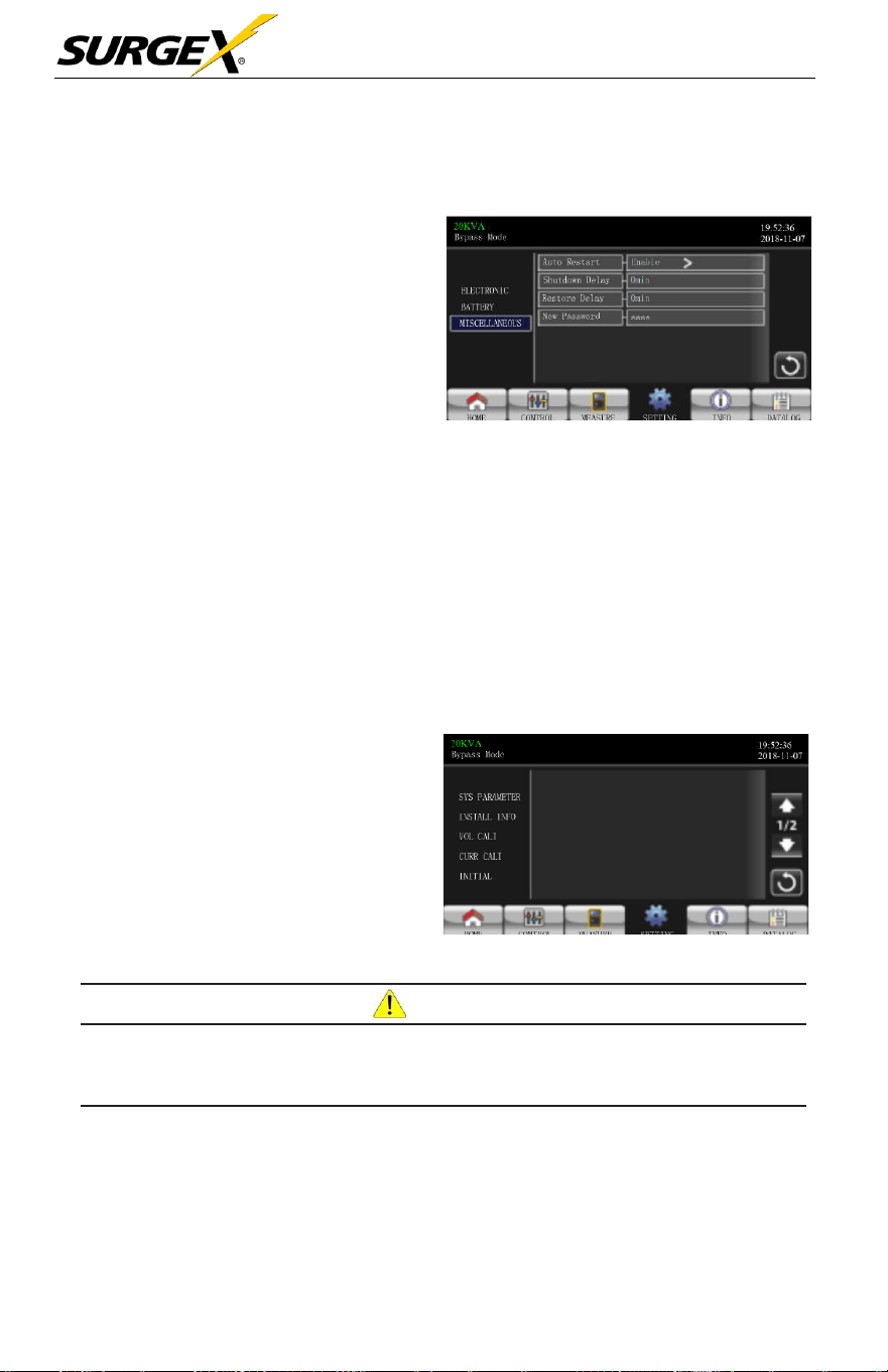
MISCELLANEOUS
➢ Auto Restart: (This function
is
reserved
for future
use)
Enable: Once “Enable” is set, and the
UPS shutdown occurs due to low
battery and the utility restores, the
UPS will return to line mode.
Disable: Once “Disable” is set,
and the UPS shutdown occurs and the
utility restores, the UPS will not
automatically turn on.
Miscellaneous Setting Page
➢ Shutdown Delay Min: UPS will shut down per delay minutes set. The
countdown
will
start after confirming the pop-up
screen.
➢ Restore Delay Min: UPS will automatically restart per restore delay minutes
set after the UPS
shuts down.
➢ New Password: Set up new
password
to enter
“ADVANCE
> User” menu.
•
ADVANCE > Maintainer
To access the “Advance > Maintainer”
Setting menu page,
it’
s
required
to enter password. Please contact your
local dealer to get maintainer
password.
Advance: Maintainer Setting Menu Page1
CAU
TION
This setting menu is only for qualified technician. Otherwise, mis-operation will
cause UPS damage.
There are five
sub-menus
under “Advance > Maintainer” setting: SYS
PARAMETER,
INSTALL
INFO, VOL CALI, CURR CALI, INITIAL,
ELECTRONIC, BATT, MISCELLANEOUS and UPS
SELFTES
T
.
Three-Phase User Manual
© 2020 AMETEK Electronic Systems Protection / Technical Support 1-800-645-9272 / surgex.com 35
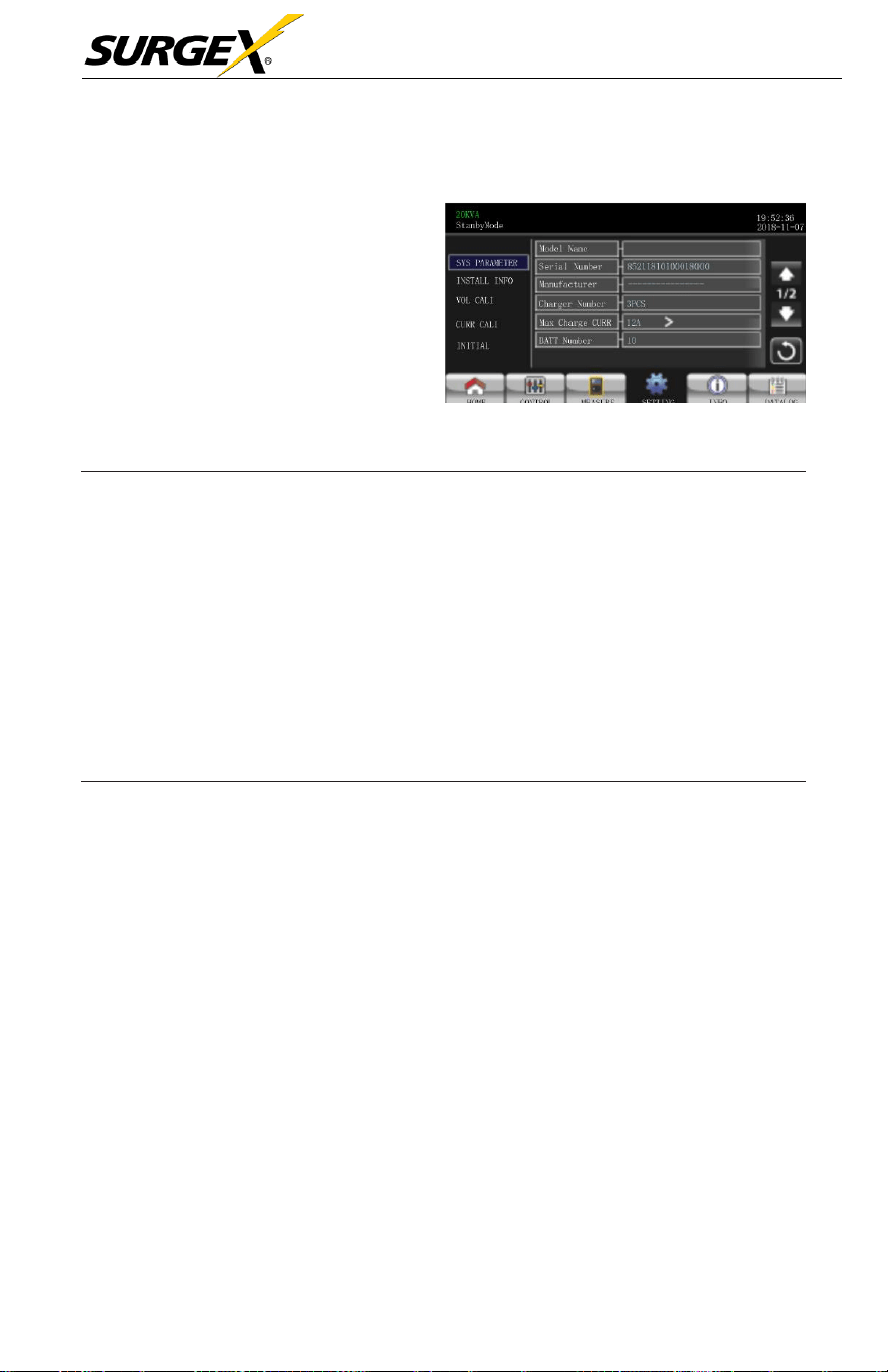
SYS PARAMETER
➢ Mode Name: Set the UPS model
name.
➢ Serial Number: Set the serial
number.
➢ Manufacturer: Set the UPS
manufacturer.
➢ Charger Number: The
number
of
charging boards installed in the UPS.
SYS Paremeter Page1
NOTE:
It’s required to restart the
UPS
after setting.
•
One piece of charger: When selected, there are four options
available for “Max Charge CURR”.
•
Two pieces of charger: When selected, there are two options
available for “Max Charge CURR”.
•
Three pieces of charger: When selected, there are three options
available for “Max Charge CURR”.
➢
Max Charge CURR: The maximum of battery
charging
current. This
parameter
setting is
related
to “Charger Number”
setting.
If
UPS is 10K, 15K or 20K, the
selectable charge
current is listed below
.
•
One piece of
charger:
There are four options, 1A, 2A, 3A, 4A. 4A
is
default
setting.
•
Two
pieces
of
charger:
There are two options, 4A and 8A. 8A
is
default
setting.
•
Three
pieces
of
charger:
There are three options, 4A, 8A, 12A. 12A
is default
setting.
•
Four
pieces
of
charger:
There are three options, 4A, 8A, 12A, 16A.
16A is default setting. (Only for 15K and 20K)
•
Five
pieces
of
charger:
There are three options, 4A, 8A, 12A, 16A,
20A. 20A is default setting (Only 15K and 20K).
Three-Phase User Manual
© 2020 AMETEK Electronic Systems Protection / Technical Support 1-800-645-9272 / surgex.com 36
If
UPS is 30K or 40K, the
selectable charge
current is listed below
.
•
One pair of
charger:
There are four options, 2A, 4A, 6A, 8A. 8A
is
default
setting.
•
Two pairs of
charger:
There are two options, 8A, 16A. 16A is
default
setting.
•
Three pairs of
charger:
There are three options, 8A, 16A, 24A. 24A
is default
setting.
➢
BATT Number: The total number of
installed
battery.
(It should restart
UPS after setting.)
The
setting
range
is 8 ~ 10. 10
is
default
setting
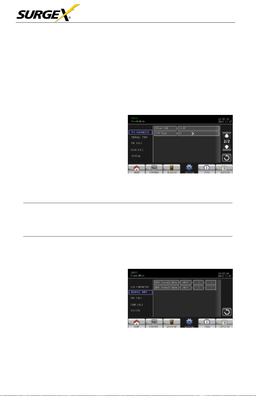
➢
The setting point of battery float
voltage. 13.6V is default
setting.
SYS Parameter Page 2
➢ UPS Type: There are two options, HV and LV. This change is only allowed
for qualified
technician.
NOTE:
It’s required to restart the
UPS
after setting.
INSTALL INFO
➢ SYS Install Date: Set the date
of UPS
installation.
➢ BAT Install Date: Set the date
of Battery
installation.
Install Info Page
Three-Phase User Manual
© 2020 AMETEK Electronic Systems Protection / Technical Support 1-800-645-9272 / surgex.com 37
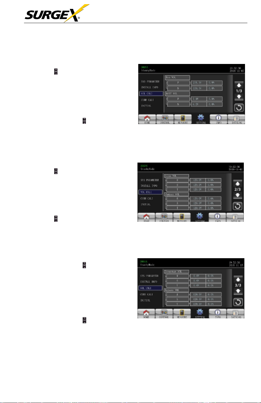
VOL CALI
➢ Bus VOL: BUS voltage calibration.
Pressing the will increase or
decrease
the calibration by
0.1%, depending
on
if
the up or
down
arrow is selected. Press
“OK” key to confirm the modification.
➢ BATT VOL: Battery voltage
calibration. Pressing the will increase or
decrease the calibrate by0.1%,
depending
on
if
the up or down arrow is
selected.
Press
“OK”
key to confirm the
modification.
VOL CALI Page 1
➢ Line VOL: Line voltage calibration.
Pressing the will increase or
decrease
the calibration by
0.1%, depending
on
if
the up or
down
arrow is selected. Press
“OK” key to confirm the modification.
➢ Output VOL: Output voltage calibration.
Pressing the will increase or decrease the
calibration by 0.1%,
depending
on
if
the
up or down arrow is
selected.
Press
“OK”
key to confirm the modification.
VOL CALI Page 2
➢ Inverter VOL: Inverter
voltage
calibration. Pressing the
will increase or decrease the
calibration by 0.1%,
depending on
if
the up or down arrow is
selected.
Press
“OK”
key to confirm
the
modification.
➢ Bypass VOL: Bypass voltage
calibration. Pressing the will
increase or decrease the calibration
by 0.1% depending on if the up or
down arrow is selected. Press “OK”
key to confirm the modification.
VOL CALI Page 3
Three-Phase User Manual
© 2020 AMETEK Electronic Systems Protection / Technical Support 1-800-645-9272 / surgex.com 38
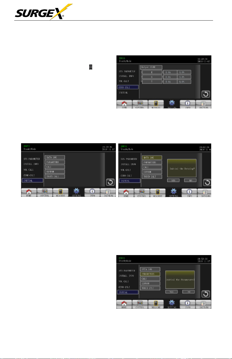
CURR CALI
➢ Output CURR: Output current
calibration. Pressing the
will increase or decrease the
calibration by 0.1%,
depending
on
if
the up or down arrow
is
selected. Press “OK” key to
confirm the modification.
INITIAL
CURR CALI Page
INITIAL MEDU Page INITIAL DATALOG Page
➢ DATA LOG: After
pressing,
the user
will
be
prompted
to
“Initial
the
Datalog?” Touch Yes to clear the DATALOG
page.
Touch Back or No to
cancel this operation and return to
INITIAL
menu
page
.
➢ PARAMETERS: After
pressing
,
the user will be prompted to
“Initial
the
Parameters?”.
Touch
Yes
to
restore
default
value
.
Touch Back
or No to cancel this operation and
return to
INITIAL
menu
page.
INITIAL PARAMETERS Page
Three-Phase User Manual
© 2020 AMETEK Electronic Systems Protection / Technical Support 1-800-645-9272 / surgex.com 39
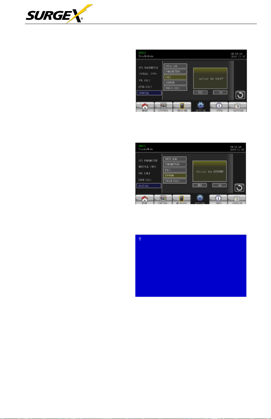
➢ CALI: After
pressing,
the user
will
be
prompted
to
“Initial
the
CALI?”. Touch YES to restore
default calibration value. T
ouch
Back or NO to cancel this
operation
and return to
INITIAL
menu page.
➢ EEPROM: After
pressing,
the
user
will
be
prompted
to “Initial
the EEPROM?”. Touch YES
to clear all setting values in
EEPROM. Touch Back or NO to
cancel this operation and return
to
INITIAL
menu
page.
➢ TOUCH CALI: After
pressing
,
the user will see the blue screen
above. Touch screen to
recalibrate
and click the + in the
upper left
corner.
INITIAL CALI Page
INITIAL CALI Page
INITIAL TOUCH Page
Three-Phase User Manual
© 2020 AMETEK Electronic Systems Protection / Technical Support 1-800-645-9272 / surgex.com 40
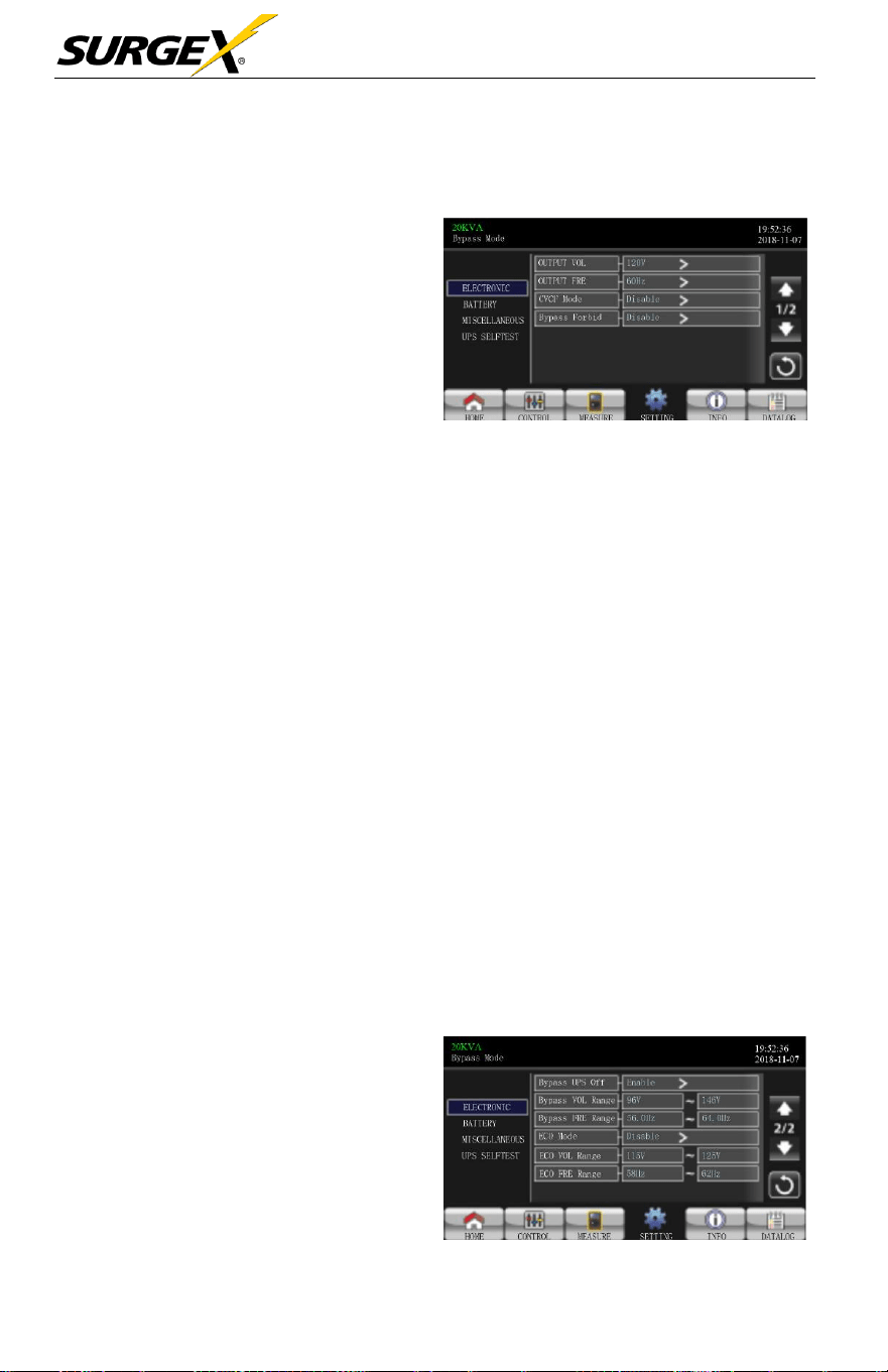
ELECTRICAL
➢ Output Voltage: Select the
output rated voltage.
There are two options, 120V
and 127V.120Vac is
default
setting.
➢ Output Rated FRE: Select
output rated
frequency
.
Electrical Setting Page
50Hz: The output
frequency
is setting for
50Hz.
60Hz: The output
frequency
is setting for
60Hz.
➢ CVCF Mode (constant voltage and constant frequency function)
Enable: CVCF function is
enabled.
The output
frequency
will
be
fixed at 50Hz or 60Hz
according
to setting of “Output Freq.”.
The
input
frequency
can
range
from 40Hz to
70Hz.
Disable: CVCF function is
disabled.
The output
frequency
will
synchronize
with the
bypass frequency
within 45~55 Hz for a
50Hz
system
or within 55~65 Hz for a 60Hz
system.
Disable is the
default
setting.
➢ Bypass Forbid:
Enable:
Bypass
Forbid is
enabled.
Running in
Bypass
mode is
not
allowed under any situations.
Disable:
Bypass
Forbid is
disabled.
UPS
will
run in
Bypass
mode. It is
the default
setting.
➢ Bypass at UPS off: When
manually turning
off
the
UPS,
select the bypass status.
This setting is only available
when “Bypass forbid” is set
to
“Disable”.
Electrical Setting Page 2

Three-Phase User Manual
© 2020 AMETEK Electronic Systems Protection / Technical Support 1-800-645-9272 / surgex.com 41
Enable: Bypass enabled. Bypass mode is activated.
Disable: Bypass disabled. There will be no output through the
Bypass
when manually turning
off
the
UPS.
➢ Bypass Voltage Range: Set the bypass voltage range.
L: Low voltage point for
bypass.
The setting
range
is 96V ~
1
10V
.
96V is default
setting.
H: High voltage point for
bypass.
The setting
range
is 130V ~ 146V
.
146V is default
setting.
➢ Bypass FRE Range: Set the
bypass frequency range.
The
acceptable bypass frequency ranges
from 46Hz to 54Hz
when
UPS is 50Hz
system
and from 56Hz to 64Hz when UPS is
60Hz
system.
➢ ECO mode:
Enable/Disable
ECO mode. Default setting is “Disable”
➢ ECO Voltage Range: Set the ECO voltage
range
.
L: Low voltage point for ECO mode. The setting
range
is from “Rated
output voltage – 5V” to “Rated output voltage - 11V”.
“Rated
output
voltage – 5V” is default
setting.
H: High voltage point for ECO mode. The setting
range
is from “Rated
output voltage + 5V” to “Rated output voltage + 11V”.
“Rated
output
voltage + 5V” is default
setting.
➢ ECO FRE Range: Set the ECO
frequency range.
The setting
range
is
from 48Hz to 52Hz when the UPS is 50Hz
system
and from
58Hz
to 62Hz
when the UPS is 60Hz
system.
Three-Phase User Manual
© 2020 AMETEK Electronic Systems Protection / Technical Support 1-800-645-9272 / surgex.com 42
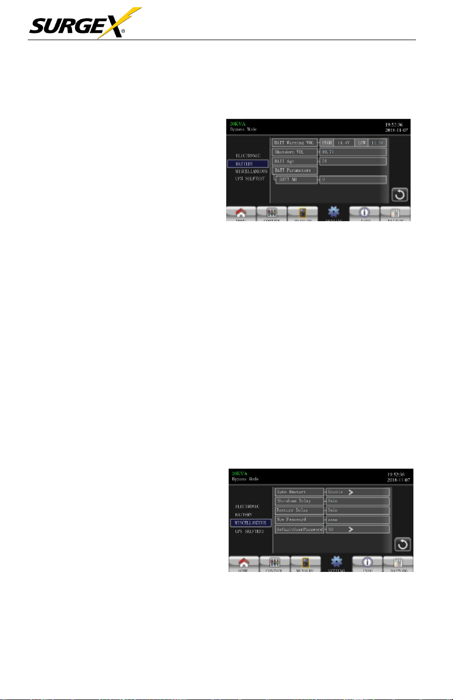
BATTERY
➢ Battery Warning Voltage:
HIGH: High battery warning
voltage. The setting range is
14.0V ~ 15.0V. 14.4V is
default
setting.
LOW: Low battery warning
voltage. The setting range
is 10.1V ~ 14.0V. 11.4V
is
default setting. This parameter
setting is related to “Shutdown
Voltage” setting. The setting
value should be higher than
“Shutdown Voltage” setting.
Battery Setting Page
➢ Shutdown Voltage:
If
battery voltage is lower than this point while in
battery mode, the UPS will automatically shut down. The setting
range
is
10.0V ~ 12.0V. 10.7V is default setting (The setting is only
available
for long-run
model)
➢ Battery Parameter:
Battery AH: setting battery capacity. 9Ah is default
setting.
MISCELLANEOUS
➢ Auto Restart:
Enable: Once “Enable” is set,
and the UPS shutdown occurs due
to low battery and the utility
restores, the UPS will return to
line mode.
Disable: Once “Disable” is set,
and the UPS shutdown occurs and
the utility restores, the UPS will
shut down per delay minutes set.
Miscellaneous Setting Page
Three-Phase User Manual
© 2020 AMETEK Electronic Systems Protection / Technical Support 1-800-645-9272 / surgex.com 43
➢ Shutdown Delay Min: UPS will shut down per delay minute set.
The
countdown
will
start after confirming the pop-up
screen.
➢ Restore Delay Min: UPS will automatically restart per restore delay
minutes
set after the UPS
shuts down.
➢ New Password: Set up User new
password
to enter “ADVANCED
User” menu page.
➢ Default User Password:
YES: User
password
will
restore
default setting
value.
NO: The UPS will cancel this operation.
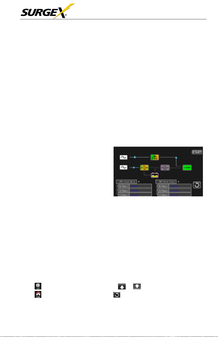
UPS SELF-TEST
This function is only effective
when
UPS type setting is
“HV”.
Therefore,
please disconnect all loads and utility
first before
executing this
function.
Then,
please change UPS
type to
“HV”.
For the
detailed
operation, please
check “System Parameter” menu under
Advanced Maintainer directory.
After
changing
UPS type to
“HV”,
you must
restart
the UPS. After
the
UPS is restarted, please enter Advance screen and enter Maintainer
password.
It
will
show “UPS SELFTEST”
selection
in the
screen.
In the
screen, all tested items are shown “unknown”. Simply click “UPS
SELFTEST” button, the UPS
will
start
self-test.
If
the UPS is
normal,
it
will show “Normal” in all columns. Otherwise, “Unknown” will be
displayed in the columns.
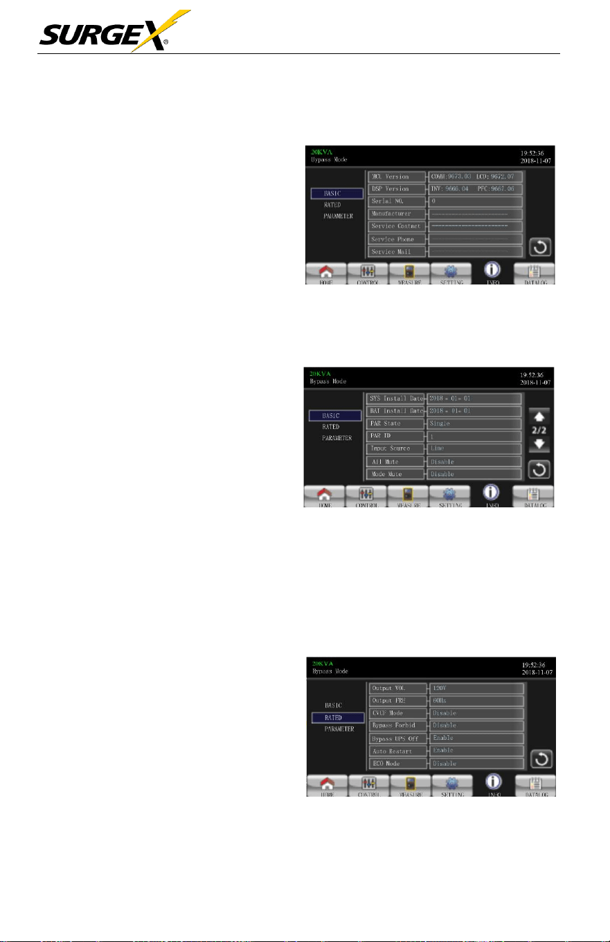
3.3.5 Information screen
Touch to enter information page. Touch or to browse information.
Touch to return to main screen. Touch to go back to previous menu.
Three-Phase User Manual
© 2020 AMETEK Electronic Systems Protection / Technical Support 1-800-645-9272 / surgex.com 44
Basic Information
➢ MCU Version: MCU
version.
➢ DSP Version: DSP version.
➢ Serial NO.: The serial number
of
UPS.
➢ Manufacturer: The information
about
manufacturer.
➢ Service Contact: The contact
name is set in “Basic Setting”.
Basic Information Page
➢ Service Phone: The listed numbers are set in “Basic Setting”.
➢ Service Mail: The service email account is set in “Basic Setting”
➢ SYS Install Date: The date of
system installation.
➢ BAT Install Date: The date of
battery installation.
➢ PAR State: The information of
parallel state.
➢ PAR ID: The UPS ID
number
in parallel state.
Basic Information Page 2
➢ Input Source: The information of input
source.
➢ All Mute:
Enable/disable
all mute function.
➢ Mode Mute:
Enable/disable
mode mute function.
Rated Information
➢ Output Voltage: Output rated
voltage.
➢ Output FRE: Output rated
frequency.
➢ CVCF Mode: Enable/Disable
CVCF
mode.
➢ Bypass Forbid: Enable/
disable bypass function.
Rated Information Page
Three-Phase User Manual
© 2020 AMETEK Electronic Systems Protection / Technical Support 1-800-645-9272 / surgex.com 45
➢ Bypass UPS Off:
Enable/disable
auto
bypass
function when
UPS
is off.
➢ Auto Restart:
Enable/disable auto-restart function.
➢ ECO Mode:
Enable/disable
ECO function.
Parameter Information
➢ Line Voltage Range: The
acceptable line input voltage
range.
➢ Line FRE Range: The
acceptable
line input
frequency
range.
➢ Bypass Voltage Range: The
acceptable input voltage range for
bypass mode.
Parameter Information Pag
➢ Bypass FRE Range: The
acceptable
input
frequency range
for
bypass mode.
➢ ECO Voltage Range: The
acceptable
input voltage
range
for
ECO
mode.
➢ ECO FRE Range: The
acceptable
input
frequency range
for
ECO
mode.
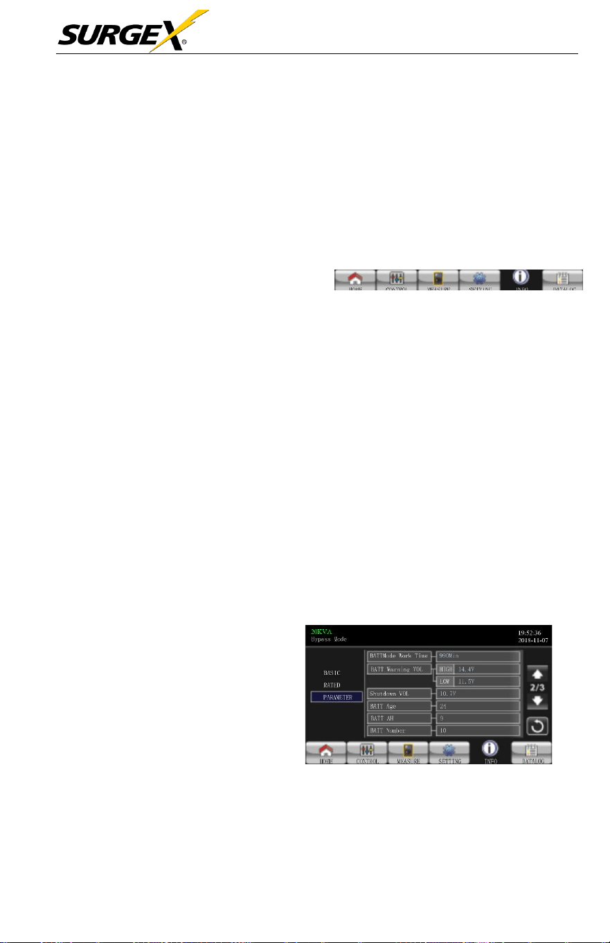
➢ BATT Mode Work Time: The
maximum
discharge
time in
battery mode.
➢ BATT Warning Voltage:
HIGH: High battery warning
voltage.
LOW: Low battery warning voltage.
Parameter Information Page 2
➢ Shutdown Voltage:
If
battery voltage is lower this point, UPS will
Automatically shut down.
Three-Phase User Manual
© 2020 AMETEK Electronic Systems Protection / Technical Support 1-800-645-9272 / surgex.com 46
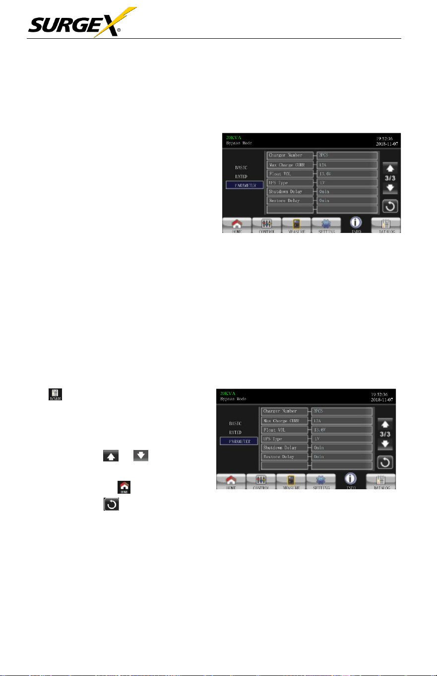
➢ Battery Age: It
shows
battery
age.
➢ Battery AH: It
shows
battery AH.
➢ Battery Number: It
shows
battery
number.
➢ Charger Number: The
information of
charger
number.
➢ Max Charge CURR: The
setting value of the
maximum
charging current.
➢ Float VOL: The setting value
of the battery float
voltage.
Parameter Information Page 3
➢ UPS Type: The information of UPS
type.
➢ Shutdown Delay: UPS will shut down in setting minutes. The
countdown
will
start after confirming the pop-up
screen.
➢ Restore Delay: UPS will automatically restart in setting minutes
after the UPS
shuts down.
3.3.6 Data Log screen
Touch to enter date log page. Data
log is used to record the
warning
and
fault information of the UPS. The record
contains date & time, code, type and
description. Touch or to page up
or down
if
there are more than
one
page
in the date log. Touch to return to
main screen. Press to go back to
main menu.
Please
refer
to
Section
3-7
and 3-8 for warning and fault code list.
Data Log Page

Three-Phase User Manual
© 2020 AMETEK Electronic Systems Protection / Technical Support 1-800-645-9272 / surgex.com 47
3.4 Audible Alarm
Description
Buzzer status
Muted
UPS status
Bypass mode
Beeping once every 2 minutes
Yes
Battery mode
Beeping once every 4 seconds
Fault
mode
Beeping continuously
Warning
Overload
Beeping twice every second
No
Others
Beeping once every second
Fault
All
Beeping continuously
Yes
3.5 Single UPS Operation
1. Turn ON the UPS with utility power (in AC mode)
a.) After the power mains is
connected
correctly, set the
battery
pack
breaker
to ON position (this step only
necessary
for long- run
model). Then set the line input breaker to ON position. At the
same
time the fan
will
start running and the UPS
will
start
initialization. In
just a few
seconds,
the UPS
will
supply
power
to the loads via the
Bypass mode.
NOTE:
When
UPS
is in Bypass mode, the output voltage will be directed
from mains after you switch on the input breaker. In Bypass mode,
the load is not protected by the
UPS.
To protect your precious
devices, you should turn on the
UPS.
Refer to next step.
b.) Touch CONTROL and
select
UPS on/of
f
icon. User
will
be
prompted to “Turn on UPS?”. Select YES. Refer to On/Of
f
UPS
screen.
Three-Phase User Manual
© 2020 AMETEK Electronic Systems Protection / Technical Support 1-800-645-9272 / surgex.com 48
c.) In just a few
seconds,
the UPS
will
enter into AC mode.
If
the mains is abnormal, the UPS will operate in Battery mode
without interruption.
NOTE:
When the
UPS
runs out of battery power, it will shut down
automatically in Battery mode. When the mains is normalized, the
UPS
will auto restart in AC mode.
2. Turn on the UPS without utility power supply (in Battery mode)
d.) Make sure that the two strings of batteries are connected correctly in
order of
”
+, GND, -” terminals and the battery pack
breaker
is in
the ON position (only for long-run
model).
e.) Press the button to set up the power supply for
the
UPS. UPS
will
enter power on mode. After initialization,
the
UPS
will enter to “No Output mode”.
f.) In just a few
seconds,
the UPS
will
be turned on and
enter
Battery mode.
3. Connect devices to UPS
After the UPS is turned on, you can
connect devices
to the
UPS.
a.) Turn on the UPS first and then switch on the
devices
one by one.
The LCD panel
will
display total load
level.
b.)
If
it is
necessary
to
connect
the inductive loads such
as a
printer,
the in-rush current of the load should be calculated carefully to
see
if
it
meets
the
overload
capability of the
UPS.
Any load more
than 150% over
designed capacity
the
runtime
will
be less than
60ms
c.)
If
the UPS is on
overload, the buzzer
will
beep
twice every
second.

Three-Phase User Manual
© 2020 AMETEK Electronic Systems Protection / Technical Support 1-800-645-9272 / surgex.com 49
d.) When the UPS is on overload, please remove some loads
immediately.
It is
recommended
to have the total
loads
connected
to the UPS less than 80% of its nominal
power
capacity
to
prevent overload
for
system
safety.
e.)
If
the
overload
time is over
acceptable
time listed in
spec
in
AC mode, the UPS
will
automatically transfer
to
Bypass mode.
After the
overloading
is
resolved,
it
will
return to AC mode.
If
the
overload time is over the acceptable time listed in the spec
in Battery mode, the UPS
will
enter “fault status”. At this time,
if
bypass
is
enabled,
the UPS
will
power to the load via
bypass.
If
bypass
function is
disabled
or the input power is not within
the
acceptable bypass range,
it
will
cut
off
output entirely
.
4. Charge the batteries
a.) After the UPS is
connected
to the mains and turned on in
AC mode, the charger will charge the batteries automatically;
except
in battery mode, during battery self-test, overload or when
battery voltage is high.
b.) It is
recommended
to
charge batteries
for at least 10
hours
before
operation. Otherwise,
the
backup
time may be
shorter
than
expected.
5. Battery mode operation
a.) When the UPS is in Battery mode, the
buzzer
will
sound
according
to different battery
capacity.
If
the battery
capacity
is more than 25%, the
buzzer
will
beep
once every 4
seconds.
If
the battery voltage drops to the alarm level, the
buzzer
will beep
once every second to remind users that the battery is at a low level
and the UPS
will
eventually
shut down. Switching of
f
some
non-
critical loads to
disable
the
shutdown
alarm
may
prolong the
backup
time.
If
there is no more load to be
switched
off, users must
prepare shutdown procedure
to
preserve working

Three-Phase User Manual
© 2020 AMETEK Electronic Systems Protection / Technical Support 1-800-645-9272 / surgex.com 50
data or
devices. Otherwise,
there is a risk of data loss or
load
failure.
b.) In Battery mode,
users
can touch
“
SETTING” è “Basic” è Audio
Mute to
enable
“Mode Mute” to
disable
the
buzzer
.
c.) The
backup
time of the long-run model
depends
on the
external
battery capacity.
d.) The
backup
time may vary from different
operating temperature
and load type.
e.) After
discharging
the default
backup
time of 16.5 hours,
the
UPS will shut down automatically to protect the battery. This
battery discharge protection can be enabled or disabled through
LCD
menu.
6. Test the Batteries
a.)
If
you
need
to check the battery
status
when the UPS
is
running in AC
mode/CVCF
mode, touch “CONTROL” and
select
“Battery Test”. Refer to “Battery Test” screen.
b.)
Users
also can set battery
self-test
through monitoring
software.
7. Turn OFF the UPS with utility power supply in AC mode
a.) Touch CONTROL and
select
the Turn
off
UPS icon to turn of
f
the UPS. Refer to “UPS on/of
f”
screen.

Three-Phase User Manual
© 2020 AMETEK Electronic Systems Protection / Technical Support 1-800-645-9272 / surgex.com 51
NOTE 1: If the
UPS
has been set to bypass output, it will bypass voltage
from the mains to output terminal even though the user has
turned off the
UPS
(inverter).
NOTE 2: After turning off the
UPS,
please be aware that the
UPS
is
working in Bypass mode and there will be risk of power loss
for connected devices.
b.) In
Bypass
mode, output voltage of the UPS is still
present.
In order
to cut
off
the output, switch
off
the line input breaker. The LCD
display
will
turn
off
and UPS is now
completely
off.
8. Turn off the UPS without utility power supply in Battery mode
a.) Touch CONTROL and
select
Turn
off
UPS icon to turn
off
the
UPS. Refer to “UPS on/of
f”
screen.
b.) Then UPS
will
cut
off
power to output
terminals
.
9. Mute the buzzer
a.) Touch SETTING and then
select
BASIC item. There are two
events available to mute. Refer to SETTING
screen.
b.) Some warning alarms cannot be muted unless the error is
fixed.
Please
refer to
section
3-4 for
details.
10. Operation in warning status
a.) When LCD
screen shows
“Fault Mode” and the
buzzer
beeps
once every second, it indicates that there are operational
problems.
Users
can read the warning
message(s)
from “DATA LOG” menu.
Please
refer to the
Section
3-3-6 for
details.
b.) Some warning alarms cannot be muted unless the error is
fixed.
Please
refer to
Section
3-4 for
details.

Three-Phase User Manual
© 2020 AMETEK Electronic Systems Protection / Technical Support 1-800-645-9272 / surgex.com 52
11. Operation in Fault mode
a.) When the
buzzer beeps continuously,
it
means
that there is
a
fatal
error with the UPS.
Users
can get the fault code from
“DATA
LOG”
menu.
Please
refer to the
Section
3-3-6 for
details
b.) Please check the loads, wiring, ventilation, mains, battery and
so
on
after the fault
occurs.
Do not try to turn on the UPS
again
before
solving the
issues.
If
the
problems persist, contact the
distributor
or service personnel immediately.
c.) In
case
of an
emergency,
shut
off
connections
from
the
mains, external battery,
and output immediately to avoid
possible
damage to the UPS or equipment.
12. Operation in maintenance mode
This
operation
should only be
performed
by
maintenance personnel or
qualified
technicians
.
When the UPS needs repair or
service
and the load
cannot
be shut off,
the UPS needs to be put into maintenance mode.
a.) First, switch
off
the
UPS
.
b.) Then,
remove
the cover of
maintenance
bypass switch on the
panel.
c.) Turn the maintenance switch to “BPS” position.
3.6 Parallel Operation
1. Parallel system initial startup
Please make sure that all the running UPSs are parallel models and
have the
same
configuration
.
a.) Turn ON each UPS in AC mode
respectively
(Refer to
section

Three-Phase User Manual
© 2020 AMETEK Electronic Systems Protection / Technical Support 1-800-645-9272 / surgex.com 53
3-5 (1)). Then, measure the inverter output voltage of
each phase
for
each
UPS with a multi-meter.
Calibrate
the
inverter
output
voltage by configuring inverter voltage
adjustment
(Refer to SETTING -> VOL CALI
screen)
in LCD menu until
the
inverter output voltage
difference
of
each
UPS is within 1V
or
less.
b.) Turn OFF each UPS (Refer to
section
3-5 (7.). Then, follow
the
wiring procedure in
section 2-5.
c.)
Remove
the cover of parallel
share
current cable port on
the
UPS,
connect each UPS one by one with the parallel cable and share current
cable, and then replace the cover.
d.) Turn ON the parallel system in AC
mode
:
• Turn on the line input
breaker
of
each
UPS.
If
using
dual-
input unit,
please
also turn on the
external bypass input
breaker.
After all
UPSs
enter
bypass
mode,
measure the
output voltage between two UPSs for the
same phase
to make sure the phase sequence is correct.
If
the
se two
voltage
differences
are near to zero, that means all
connections are met. Otherwise, please check
if
the
wirings are connected correctly.
• Turn ON the output
breaker
of
each UPS.
• Turn ON
each
UPS in turns. After a while, the
UPSs
should
enter into AC mode
synchronously
and then, the parallel
system is now complete.
e.) Turn ON the parallel system in Battery mode:
f.) Turn ON the battery
breaker
(only
available
in long-run
model)
and
external
output
breaker
of
each UPS.
• Turn ON any UPS. A few
seconds
later, the UPS
will
enter
battery mode.

Three-Phase User Manual
© 2020 AMETEK Electronic Systems Protection / Technical Support 1-800-645-9272 / surgex.com 54
• Turn ON the next UPS in
sequence
until all the
UPSs
enter
Battery mode and are added to the parallel system. Now the
parallel system is now complete.
For more information
regarding
the parallel
operation,
please contact
SurgeX Technical Support for detailed instruction.
2. Add new units into the parallel system
a.) You cannot add new units into the parallel system when the whole
system
is running. You must cut
off
the load and
shut
down the
system.
b.) Make sure all
UPSs
are the parallel
models
and follow
the
wiring
reference
in
section 2-5.
c.) Install the new parallel
system as
per
section 2-6.
d.)
Remove
units from the parallel
system.
There are two
methods
to
remove
units from the parallel
system:
First Method:
a.) Touch “CONTROL” è “Turn
off
UPS” and
select
“Yes” to turn off
the UPS. Then, the UPS will enter Bypass mode or No Output mode
without output.
b.) Turn
off
the
external
output
breaker
on this unit, and then
turn
off
the input
breaker
of this unit.
c.) Turn
off
the battery
breaker
(only
available
in long-run
model)
and remove the parallel and share current cables. And then remove
the unit from the parallel system.
Second Method:
a.)
If
the bypass is abnormal, you cannot remove the UPS without
interruption. You must cut
off
the load and shut down
the
system.

Three-Phase User Manual
© 2020 AMETEK Electronic Systems Protection / Technical Support 1-800-645-9272 / surgex.com 55
b.) Make sure the bypass setting is enabled in each UPS and
then turn
off
the
system.
All
UPSs
will
transfer
to
Bypass
mode. Remove all the maintenance bypass covers and set the
maintenance switches
from “UPS” to “BPS” position. Turn
off
all
the input breakers and battery breakers in parallel system.
c.) Turn OFF the output
breaker
and remove the parallel cable
and
share
current cable of the UPS which you want to remove. Now,
you can remove the UPS from parallel system.
d.) Turn ON the input
breaker
of the
remaining
UPS and
the system
will
transfer
to
Bypass
mode. Set the maintenance
switches
from
“BPS” to “UPS position and put the
maintenance
bypass covers
back on.
e.) Turn ON the remaining UPS according to the previous section.
W
ARN
I
N
G
(
Onl
y
f
o
r
P
ara
ll
e
l S
ystem)
● Before turning on the parallel system to activate inverter, make
sure that all units’ maintenance switches are in the same position.
● When parallel system is turned on, please do not operate the
maintenance switch of any unit.
● The parallel system DOES NOT support ECO mode.
Therefore, please DO NOT “enable” ECO mode in any unit.

Three-Phase User Manual
© 2020 AMETEK Electronic Systems Protection / Technical Support 1-800-645-9272 / surgex.com 56
3.7 Fault Code
Fault
Code
Fault Event
Icon
Fault
Code
Fault Event
Icon
01
Bus start failure
None
42
DSP communication failure
None
02
Bus over
None
43
Overload
None
03
Bus under
None
46
Incorrect UPS setting
None
04
Bus unbalance
None
47
MCU communication failure
None
06
Converter
over
current
None
48
Two DSP firmware
versions
are incompatible in parallel
system.
None
11
Inverter soft start failure
None
49
Input and output
phase are
incompatible
None
12
High inverter voltage
None
60
Bypass phase short circuited
None
14
Inverter R output (line to
neutral) short circuited
61
Bypass
SCR short circuited
15
Inverter S output (line to
neutral) short circuited
None
62
Bypass
SCR open circuited
None
16
Inverter T output (line to
neutral) short circuited
None
63
Voltage waveform abnormal in
R phase
None
17
Inverter R-S output (line to
line) short circuited
None
64
Voltage waveform
abnormal
in S phase
None
18
Inverter S-T output (line to
line) short circuited
None
65
Voltage waveform abnormal in
T phase
None
19
Inverter T-R output (line to
line) short circuited
None
66
Inverter current
sample
abnormal
None
1A
Inverter R negative power
fault
None
67
Bypass O/P short circuited
None
1
B
Inverter S negative power
fault
None
68
Bypass O/P line to line short
circuited
None
1
C
Inverter T negative power
fault
None
69
Inverter SCR short circuited
None
21
Battery SCR short circuited
None
6C
BUS voltage drops too
fast
None
23
Inverter relay open circuited
None
6D
Current
sampling
error
value
None
24
Inverter relay short circuited
None
6E
SPS power error
None
25
Line wiring fault
None
6F
Battery polarity reverse
None
31
Parallel communication failure
None
71
PFC IGBT over-current in R
phase
None
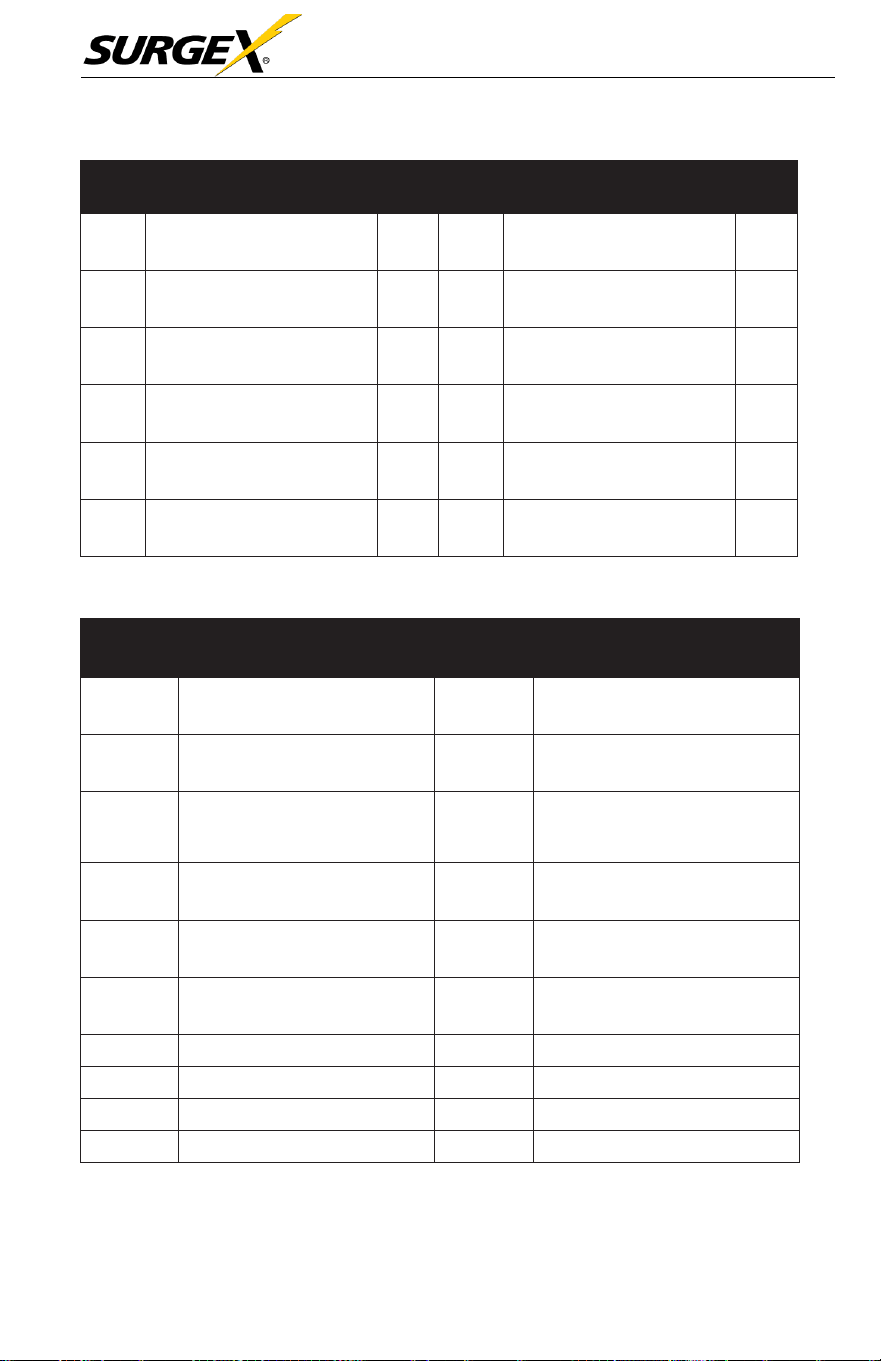
Three-Phase User Manual
© 2020 AMETEK Electronic Systems Protection / Technical Support 1-800-645-9272 / surgex.com 57
Fault
Code
Fault Event
Icon
Fault
Code
Fault Event
Icon
32
The host signal failure
None
72
PFC IGBT over-current in S
phase
None
33
Synchronous
signal failure
None
73
PFC IGBT over-current in T
phase
None
34
Synchronous trigger signal
failure
None
74
INV IGBT over-current in R
phase
None
35
Parallel communication loss
None
75
INV IGBT over-current in
S
phase
None
36
Parallel output current
unbalance
None
76
INV IGBT over-current in T
phase
None
41
Over temperature
None
77
LCD & MCU communication
failure
None
3.8 Warning Code
Warning
Code
Warning Event
Warning
Code
Warning Event
01
Battery unconnected
21
Line
situations
are different in
parallel system
02
IP Neutral
loss
22
Bypass situations
are
dif
ferent
in parallel system
04
IP
phase
abnorma
l
33
Locked in
bypass after
overload 3 times in 30
minutes
05
Bypass phase abnormal
34
Converter
current unbalanced
07
Over charge
3A
Cover of maintain switch
is
open
08
Low battery
3C
Utility
extremely unbalanced
09
Overload
3D
Bypass is unstable
0A
Fan failure
3E
Battery voltage too high
0B
EPO enable
3F
Battery voltage unbalanced
0D
Over temperature
40
Charger
short circuited

Three-Phase User Manual
© 2020 AMETEK Electronic Systems Protection / Technical Support 1-800-645-9272 / surgex.com 58
4.0 TROUBLESHOOTING
If
the UPS
system does
not
operate
correctly,
please
solve the
problem
by using the table below.
Symptom
Possible Cause
Remedy
No indication and alarm in
the front display panel even
though the mains is normal.
The AC input power is not
connected well.
Check if input cable firmly
connected to the mains.
The warning code 0B.
EPO function is activated.
The EPO switch is in
“OFF” status or the jumper is
open.
Set the circuit in close
d
position to disable the
EPO function.
The warning code 01.
The external or internal
battery is incorrectly
connected.
Check if all batteries are
connected well.
The warning code 09.
UPS is overloaded.
Remove excess loads
from UPS output.
UPS is overloaded. Devices
connected to the UPS are fed
directly by the electrical
network via the Bypass.
Remove excess loads
from UPS output.
After repetitive overloads, the
UPS is locked in the Bypass
mode. Connected devices are
fed directly from the mains.
Remove excess loads
from UPS output first. Then
shut down the UPS and restart
it.
Fault code is shown as 43.
UPS is overloaded too
long and becomes fault.
Then UPS shuts down
automatically.
Remove excess loads
from UPS output and
restart it.
Fault code is shown as 14,
15, 16, 17, 18 or 19,
The UPS shuts down
automatically because a short
circuit occurs on the UPS
output.
Check output wiring and if
connected devices are in
short circuit status.
Other fault codes are shown
on the LCD display and the
alarm beeps continuously.
A UPS internal fault has
occurred.
Contact SurgeX

Three-Phase User Manual
© 2020 AMETEK Electronic Systems Protection / Technical Support 1-800-645-9272 / surgex.com 59
Symptom
Possible Cause
Remedy
Battery backup time is shorter
than nominal value.
Batteries are not fully
charged.
Charge the batteries for at
least 7 hours and then check
capacity. If the problem
still persists, consult
SurgeX.
Batteries defect
Contact SurgeX to
replace the battery.
The warning code 0A.
Fan is locked or not
working. Or the UPS
temperature is too high.
Check fans and notify
dealer.
The warning code 02.
The input neutral wire is
disconnected.
Check and correct the input
neutral connection. If the
connection is ok and the
warning is still displaying,
please check input fuses of
S and T.
The S or T input fuse is
broken.
Replace the fuse.
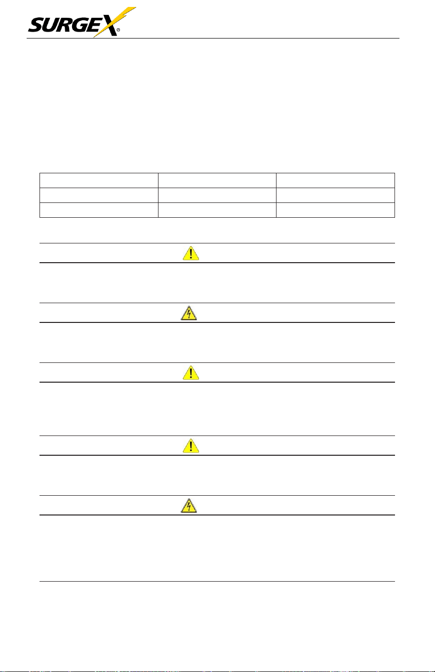
Three-Phase User Manual
© 2020 AMETEK Electronic Systems Protection / Technical Support 1-800-645-9272 / surgex.com 60
5.0 STORAGE AND MAINTENANCE
5.1 Storage
Before storing, charge the UPS at least 7 hours. Store the charged UPS
covered and upright in a cool, dry location. During storage, recharge the
battery in accordance with the following table:
Storage Temperature
Recharge Frequency
Charging Duration
-25°C -
40°C
Every 3 months
1-2
hours
40°C -
45°C
Every 2 months
1-2
hours
5.2 Maintenance
CAU
TION
The UPS system utilizes hazardous voltages. Repairs may be carried out only by
factory authorized service personnel.
W
ARN
ING
Even after the unit is disconnected from the mains, components inside the UPS
system are still connected to the battery packs which are potentially dangerous.
CAU
TION
Before carrying out any kind of service and/or maintenance, disconnect the
batteries and verify that no current is present, and no hazardous voltage exists in the
terminals of high capability capacitor such as BUS-capacitors.
CAU
TION
Only factory authorized personnel may replace batteries and/or perform service
operations. Unauthorized persons must be kept well away from the batteries.
W
ARN
ING
Verify that no voltage is present between the battery terminals and the ground
before maintenance or repair. In this product, the battery circuit is not isolated from
the input voltage. Hazardous voltages may occur between the battery terminals and
the grounding/earthing.
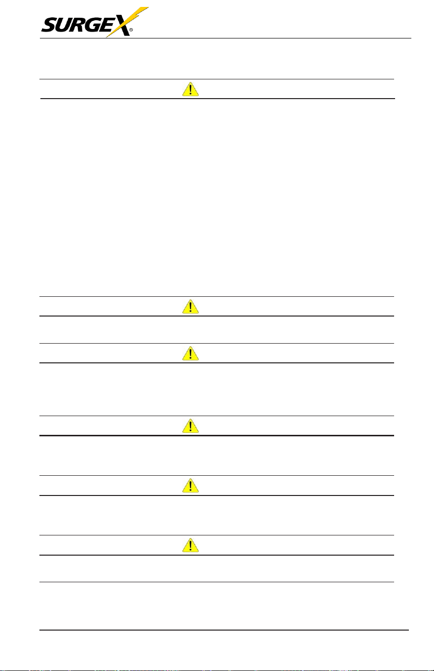
Three-Phase User Manual
© 2020 AMETEK Electronic Systems Protection / Technical Support 1-800-645-9272 / surgex.com 61
CAU
TION
Batteries may cause electric shock and have a high short-circuit current. The
following precautions should be observed when working on batteries:
a) Remove watches, rings, or other metal objects.
b) Use tools with insulated handles.
c) Wear rubber gloves and boots.
d) Do not lay tools or metal parts on top of batteries.
e) Disconnect charging source prior to connecting or disconnecting battery
terminals.
f) Remove battery grounds during installation and maintenance to reduce
likelihood of shock. Remove the connection from ground if any part of
the battery is determined to be grounded.
CAU
TION
Batteries must only be replaced by the same number and battery type.
CAU
TION
Do not attempt to dispose of batteries by burning them. This could cause battery
explosion. The batteries must be disposed in compliance with all local
environmental regulations.
CAU
TION
Do not open or destroy batteries. Escaping electrolyte can cause injury to the skin
and eyes. It may be toxic.
CAU
TION
Please replace the fuses only with the same type and amperage in order to avoid fire
hazards.
CAU
TION
Do not disassemble the UPS system.
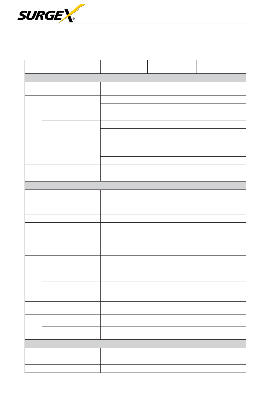
Three-Phase User Manual
© 2020 AMETEK Electronic Systems Protection / Technical Support 1-800-645-9272 / surgex.com 62
Time
6.0 SPECIFICATIONS
CAPACITY*
20KVA /
20KW
30KVA/
30KW
40KVA/
40KW
INPUT
Nominal Voltage
3 x 208/220 VAC (Ph-Ph)
3 x 120/127 VAC (Ph-N)
Voltage
Range
Low Line Loss
138 VAC (Ph- Ph ) ± 3 % at 50% Load
172 VAC (Ph- Ph) ± 3 % at 100% Load
Low Line Comeback
Low Line Loss Voltage + 5V
High Line Loss
270 VAC (Ph- Ph) ± 3 % at 50% Load
253 VAC (Ph- Ph) ± 3 % at 100% Load
High Line Comeback
High Line Loss Voltage - 5V
Frequency Range
46Hz ~ 54 Hz
@
50Hz system
56Hz ~ 64 Hz
@
60Hz system
Phase
3 Phase with Neutral
Power Factor
≧0.99 at 100% Load
OUTPUT
Phase
3 Phase with Neutral
Output Voltage
3 x 208/220 VAC (Ph-Ph)
3 x 120/127 VAC (Ph-N)
AC Voltage Regulation
± 1%
Frequency Range
(Synchronized Range)
46Hz ~ 54 Hz
@
50Hz system
56Hz ~ 64 Hz
@
60Hz system
Frequency Range (Batt.
Mode)
50 Hz ± 0.1 Hz or 60Hz ± 0.1 Hz
Overload
AC Mode
>300%: 140 ms
>130%: 1s
110%~130%: 1m
100%~110%: 1h
Battery Mode
100%~110%: 30sec; 110%~130%: 10sec; >130% : 1sec
Current Crest Ratio
3:1 max
Harmonic Distortion
≦2 %
@
100% Linear Load; ≦ 4 %
@
100% Non-linear
Load (PF≥0.8)
Transfer
Line Battery
0 ms
Inverter Bypass
0 ms (When phase lock fails, <4ms interruption occurs
from inverter to bypass)
EFFICIENCY
AC Mode
94%
Battery Mode
92.50%
ECO Mode
97%
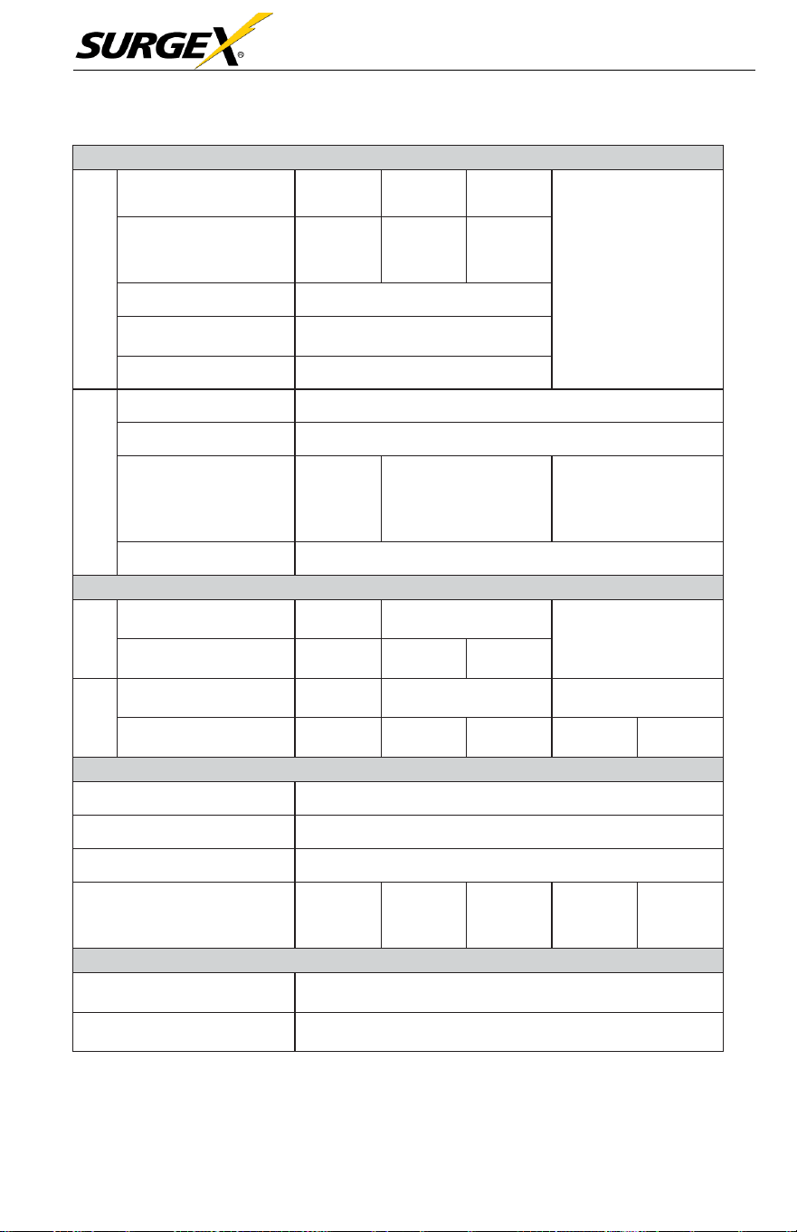
Three-Phase User Manual
© 2020 AMETEK Electronic Systems Protection / Technical Support 1-800-645-9272 / surgex.com 63
Model
BATTERY
Standard
Model
Type
12 V /
9 Ah
12 V /
9 Ah
12 V /
9 Ah
N/A
Numbers
(10+10)
pcs
x 1 string
(10+10)
pcs
x 2 strings
(10+10)
pcs
x 3 strings
Recharge Time
9 hours recover to 90% capacity
Charging Current
(max.)
1A/2A/3A/4A (Adjustable)
Charging Voltage
+/-136.5 VDC ± 1%
Long-run Model
Type
Depending on applications
Numbers
8 ~ 10 (adjustable)
Charging Current
(max.)
4A/8A/12A
(Adjustable)
4A/8A/12A (Adjustable)
Optional parallel up to
Max. 20A
4A/8A/12A/16A
(Adjustable)
Optional parallel up to
Max. 24A
Charging Voltage
+/- 13.65 VDC * N ± 1% (N = 8~10)
PHYSICAL
Standard
Model
Dimension,
D x W x H (mm)
667 x 250
x 827
865 x 300 x 1020
N/A
Net Weight (kgs)
95
181
231
Long-run
Dimension,
D x W x H (mm)
667 x 250
x 827
865 x 300 x 1020
790 x 420 x 1200
Net Weight (kgs)
45
80
81
150
160
ENVIRONMENT
Operation Temperature
0 ~ 40°C (the battery life will down when > 25°C)
Operation Humidity
<95 % and non-condensing
Operation Altitude**
<1000m**
Acoustic Noise Level
Less than
60dB
@
1
Meter
Less than
70dB
@
1
Meter
Less than
70dB
@
1
Meter
Less than
70dB
@
1
Meter
Less than
75dB
@
1
Meter
MANAGEMENT
Smart RS-232 or USB
Supports Windows® 2000/2003/XP/Vista/2008/7/8/10,
Linux, Unix, and MAC
Optional SNMP
Power management from SNMP manager and web
browser
* If the UPS is installed or used in a place where the altitude is above than
1000m, the output power must be de-rated 1% per 100m.
** Product specifications are subject to change without further notice.
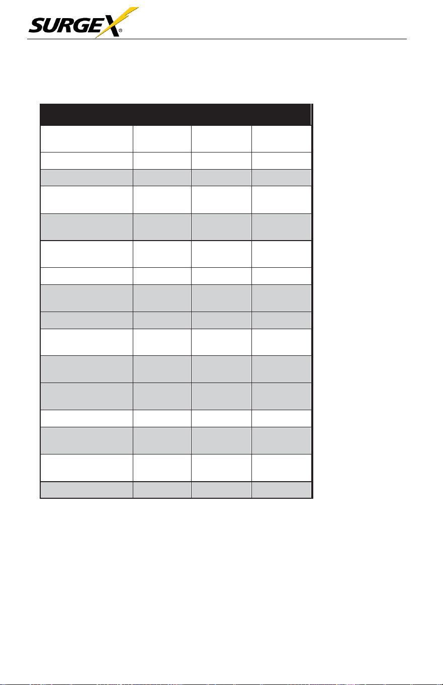
Three-Phase User Manual
© 2020 AMETEK Electronic Systems Protection / Technical Support 1-800-645-9272 / surgex.com 64
Facility Data Planning Guide Three-Phase UPS
20-40kVA UPS (208V input, 208V output)
Power Rating (kVA/
kW)
20/20
30/30
40/40
Voltage
208 VAC
208 VAC
208 VAC
kW (Nom./Max)
20/20
30/30
40/40
Current (Nom./
Max)
56/67
83/100
111/134
Min. Input AWG
(includes Neutral)
6
3
1/0
External Overcur-
rent Protection
70A
1
10A
150A
Nominal Voltage
240V DC
240V DC
240V DC
Maximum Dis-
charge
83A/string
125A/
string
167A/
string
Current Nominal
56
83
111
Minimum Output
AWG
6
3
2
External Overcur-
rent Protection
70
100
125
Dimensions
W x D x H
12” x 34”
x
40
17” x 31” x
47”
17” x 31”
x 47”
Weight lbs.
508
330
362
Floor Loading lbs./
sq.in.
1.24
.70
.70
Height Rejection
kBTU/Hr.
5.14
7.70
10.27
Cooling Air CFM
612
1224
1224

Three-Phase User Manual
© 2020 AMETEK Electronic Systems Protection / Technical Support 1-800-645-9272 / surgex.com 65
Notes:
1. Nominal (Nom.) current based on
rated load
2. Maximum (Max.) current based on
173V
(@100%
load) input voltage
3. Input and output cables typically run in
separate conduits.
4. If initial load is less than
UPS
rated
output, it is recommended that
AC input, battery, and AC output
wiring and overcurrent protection be
sized to
UPS
full load rating to
accommodate possible to future
expansion.
5. Nominal battery voltage - (lead
technology) (2.0 volts/ cell, cutoff 1.7
volts/cell)
6. If user provided DC cables should be
sized for not more than a 2.0% line drop
at maximum
7. Suggested AC output overcurrent
protection based on continuous full
load current per NEC 210-20.
8. All wiring to be in accordance with the
applicable national and/or local
electrical codes. (Conductor sizes
based on insultation rated at 90
o
C)
9. Minimum access clearance per UPS
Owner’s Manual
10. Control wiring and power wiring to be
run in separate conduit.
11. Nominal output current based on
matching AC input / output voltages
12. 240V DC with Neutral (10+10)
Additional Notes:
A. Ratings of cables and overcurrent
devices supplied for information
only. User to consult with it’s
own engineering services before
adopting.
B. Reference NEC handbook. Consult
local codes for possible variations.
UPS Connections:
•
10 kVA - Terminals with M5 bolt
*
Calculation based
on
ambient operating temperature
of 25
o
C

Three-Phase User Manual
© 2020 AMETEK Electronic Systems Protection / Technical Support 1-800-645-9272 / surgex.com 66
Life Critical Applications
While
SurgeX believes
it
designs
and
manufactures
very
reliable
Products,
many of the
vendors
that
SurgeX sources components from
do not
recommend
or
endorse
the use of their
Products
in life critical
applications.
By
extension, SurgeX
must
adhere
to the
same business
policy and
does
not
recommend
the use of our
Products
in life critical applications.
Disclaimer
SurgeX Products
are not
designed, intended, authorized, tested, or
UL
Listed for use in
systems intended
to
support
or
sustain
life, or for any
other
application
in which the failure of a
SurgeX Product could
create a
situation where personal injury or death may occur. Should Buyer
purchase
or use
SurgeX Products
for any such
unintended or unauthorized
application,
Buyer shall indemnify and hold
SurgeX
and
its officers,
employees, subsidiaries,
affiliates and
distributors
harmless against
all
claims,
costs, damages
and
expenses,
and
reasonable
attorney
fees
arising out of, directly or indirectly, any claim or
personal
injury or
death
associated
with such
unintended
or
unauthorized
use,
even
if
such claim
alleges
that
SurgeX
was
negligent regarding the design
or
manufacture
of the
part.

Three-Phase User Manual
© 2020 AMETEK Electronic Systems Protection / Technical Support 1-800-645-9272 / surgex.com 67
