
MILWAUKEE ELECTRIC TOOL CORPORATION
13135 W. Lisbon Road, Brookeld, WI 53005
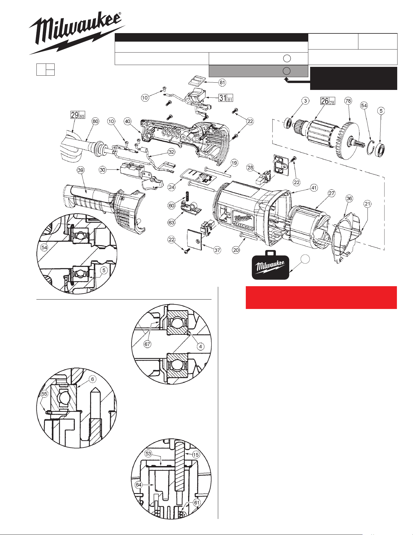
Drwg. 4
FIG. PART NO. DESCRIPTION OF PART QTY.
3 02-04-0852 Ball Bearing (1)
5 02-04-1204 Ball Bearing (1)
10 05-78-0305 M3.5 x 0.6 x 7mm Pan Hd. Slotted T-15 (4)
19 06-82-5554 10-24 x 2.375 Taptite T-25 (2)
20 06-82-5584 10-24 x 1.50 Taptite T-25 (2)
21 06-82-7375 8-16 x 2.50 Slotted Plastite T-20 (2)
22 06-82-9220 K40 x 5/8 Slotted PT T-20 (7)
24 12-98-7305 Service Nameplate (1)
26 16-50-1095 Armature Assembly (1)
27 18-50-1095 Field (1)
28 22-20-0150 Brush Holder Assembly (2)
29 22-64-1260 Cord Assembly (1)
30 23-66-2270 On/O Switch (1)
31 23-66-2365 Reversing Switch Assembly (1)
32 23-94-2270 Lead Wire Assembly (1)
36 31-05-0240 Bae (1)
37 31-15-0595 Brush Cover (2)
39 31-44-2165 Handle Half - Right (1)
40 31-44-2170 Handle Half - Left (1)
41 31-50-1780 Motor Housing with Trace (1)
54 34-80-2021 Beveled Internal Retaining Ring (1)
60 40-50-0265 Rotation Button Spring (1)
63 42-42-0490 Rotation Release Button (1)
78 22-84-0085 Fan (1)
80 44-76-0355 Cord Protector (1)
81 42-38-0280 Rocker Boot (1)
83 48-55-1680 Accessory Carrying Case (1)
58-01-0695
1680-20
54-10-0251
407B 4
SUPER HAWG
®
REVISED BULLETIN
DATE
SERVICE PARTS LIST
BULLETIN NO.
WIRING INSTRUCTION
CATALOG NO.
SPECIFY CATALOG NO. AND SERIAL NO. WHEN ORDERING PARTS
STARTING
SERIAL NUMBER
May 2018
Orient the pin (15) with the
rounded end facing up,
as shown.
Orient the retaining ring (53)
with the barbs facing up,
as shown.
Insert the straight end of the
spring (61) into the hole in the
bottom of the shift disk (64).
Orient the
retaining ring (54)
with the bevel away
from the bearing (5),
as shown.
Orient the bearing
retainer (67) with the
oset away from the
bearing (4), as shown.
Orient the retaining
ring (55) with the
bevel facing away
from the bearing (6),
as shown.
EXAMPLE:
Component Parts (Small #) Are Included
When Ordering The Assembly (Large #).
0
00
SERVICE DETAILS FOR
PARTS ON THE BACK PAGE
54-10-0250
= Part number change
from previous service
parts list.
STARTING
SERIAL NUMBER
407B D
See 5th character in serial number
on tool nameplate to order proper
Spiral Bevel Gear and Spiral Bevel
Pinion on page 2.
83
FOR TOOLS WITH A FAILED MOTOR PINION (ITEM #26)
OR 1ST INTERMEDIATE GEAR (ITEM #45), REPAIR WITH
SERVICE KIT 14-30-0390.
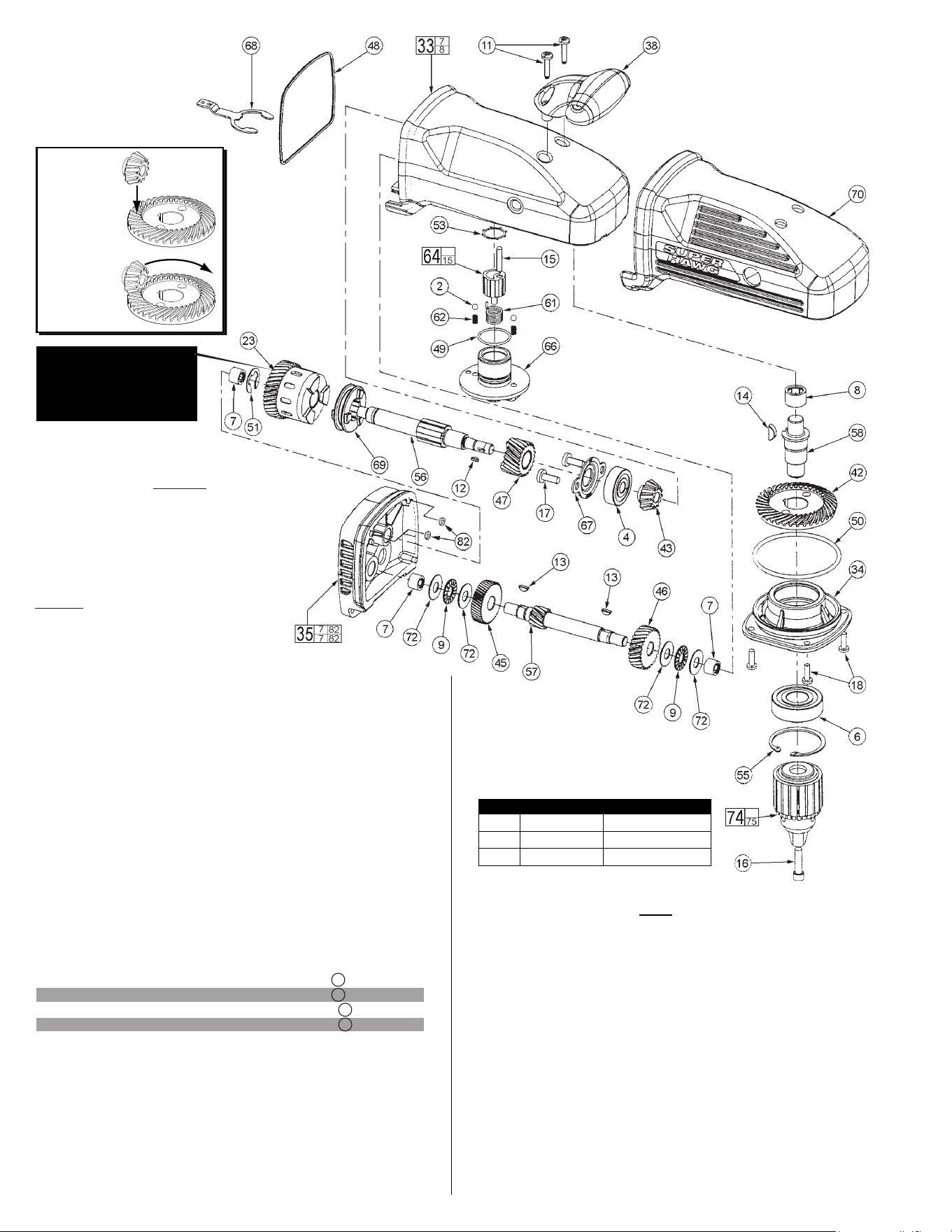
FIG. PART NO. DESCRIPTION OF PART QTY.
58 38-50-4460 Spindle (1)
61 40-50-8585 Torsion Spring (1)
62 40-50-8690 Detent Spring (2)
64 43-06-0696 Shifting Disk Assembly (1)
66 43-98-0665 Shifting Knob (1)
67 44-86-0040 Bearing Retainer (1)
68 44-86-0045 Retaining Fork (1)
69 44-90-0575 Shifting Ring (1)
70 45-12-0625 Gearcase Insulator (1)
72 45-88-0395 Thrust Washer (4)
74 48-66-1381 Chuck (1)
75 48-66-3280 Chuck Key (Not Shown) (1)
76 48-66-4040 Chuck Key Holder (Not Shown) (1)
77 49-15-0151 Side Handle Assembly (Not Shown) (1)
82 34-40-1680 Screw Gasket (2)
Fill the gear cavity of the gear
case (33) with 8.5 oz. of grease.
Fill the spindle cavity of the gear
case (33) with 3.5 oz. of grease.
Lightly grease o-ring (49)
before assembling to the
shift knob (66).
SCREW/CHUCK TORQUE CHART
FIG. PART NO. SEAT TORQUE
10 05-78-0305 4-10 In.-Lbs.
74 Chuck 80-90 Ft.-Lbs.
Note: Chuck Assembly No. 48-66-1381
comes with a washer that is not to
be used when servicing this tool.
= Part number change
from previous service
parts list.
Fig. 23, No. 32-10-1058
Clutch Assembly- has
been "calibrated" at the
factory and requires no
"run-in".
IMPORTANT!
Check gear
mesh for proper
pinion tracking
on bevel gear
before tool is
re-assembled.
FIG. PART NO. DESCRIPTION OF PART QTY.
2 02-02-1300 5mm Ball (2)
4 02-04-1055 Ball Bearing (1)
6 02-04-2031 Ball Bearing (1)
7 02-50-7000 Needle Bearing (3)
8 02-50-7005 Needle Bearing (1)
9 02-80-0180 Thrust Needle Bearing (2)
11 05-88-9915 M5 x 1.23 x 25mm Pan Hd. DG T-25 (2)
12 06-42-0800 Woodru Key (1)
13 06-42-1900 Woodru Key (2)
14 06-42-2400 Woodru Key (1)
15 06-65-2010 Dowel Pin (1)
16 06-75-3150 1/4-20 x 1 LH Socket Hd. Screw (1)
17 06-82-5360 1/4-20 x .625 Taptite T-30 (2)
18 06-82-5411 10-24 x .625 Taptite T-25 (4)
23 32-10-1058 Clutch Assembly (1)
33 28-14-2546 Gearcase Assembly (1)
34 28-20-2600 Gearcase Cover (1)
35 28-28-2185 Diaphragm Assembly (1)
38 31-44-2060 Gearcase Front Handle (1)
42 32-05-1515 Spiral Bevel Gear (For 407B 4 tools) (1)
42 32-05-1516 Spiral Bevel Gear (For 407B D tools) (1)
43 32-05-1520 Spiral Bevel Pinion (For 407B 4 tools) (1)
43 32-05-1521 Spiral Bevel Pinion (For 407B D tools) (1)
45 32-42-1380 1st Intermediate Gear (1)
46 32-42-1400 1st Intermediate Gear - High (1)
47 32-44-1340 2nd Intermediate Gear - High (1)
48 34-40-0230 Gearcase Seal (1)
49 34-40-4545 O-Ring (1)
50 34-40-4550 O-Ring (1)
51 34-60-1450 E-Ring (1)
53 34-80-1800 Internal Retaining Ring (1)
55 34-80-2980 Internal Beveled Retaining Ring (1)
56 36-18-0585 Intermediate Shaft (1)
57 36-66-1225 1st Intermediate Pinion - Low (1)
LUBRICATION NOTES:
Type 'Y' Grease No. 49-08-5270,
6oz./170g tube
The entire amount of two tubes will be needed.
or
Type 'Y' Grease No. 49-08-5275, 14oz./396g tub (can)
When servicing, remove 90-95% of existing grease
prior to installing Type 'Y'. Original grease may be
similar in color but not compatible with 'Y'.
DO NOT wash Clutch Hub Assembly #23.
Prior to reinstalling, clean gear assemblies
with a clean dry cloth.