
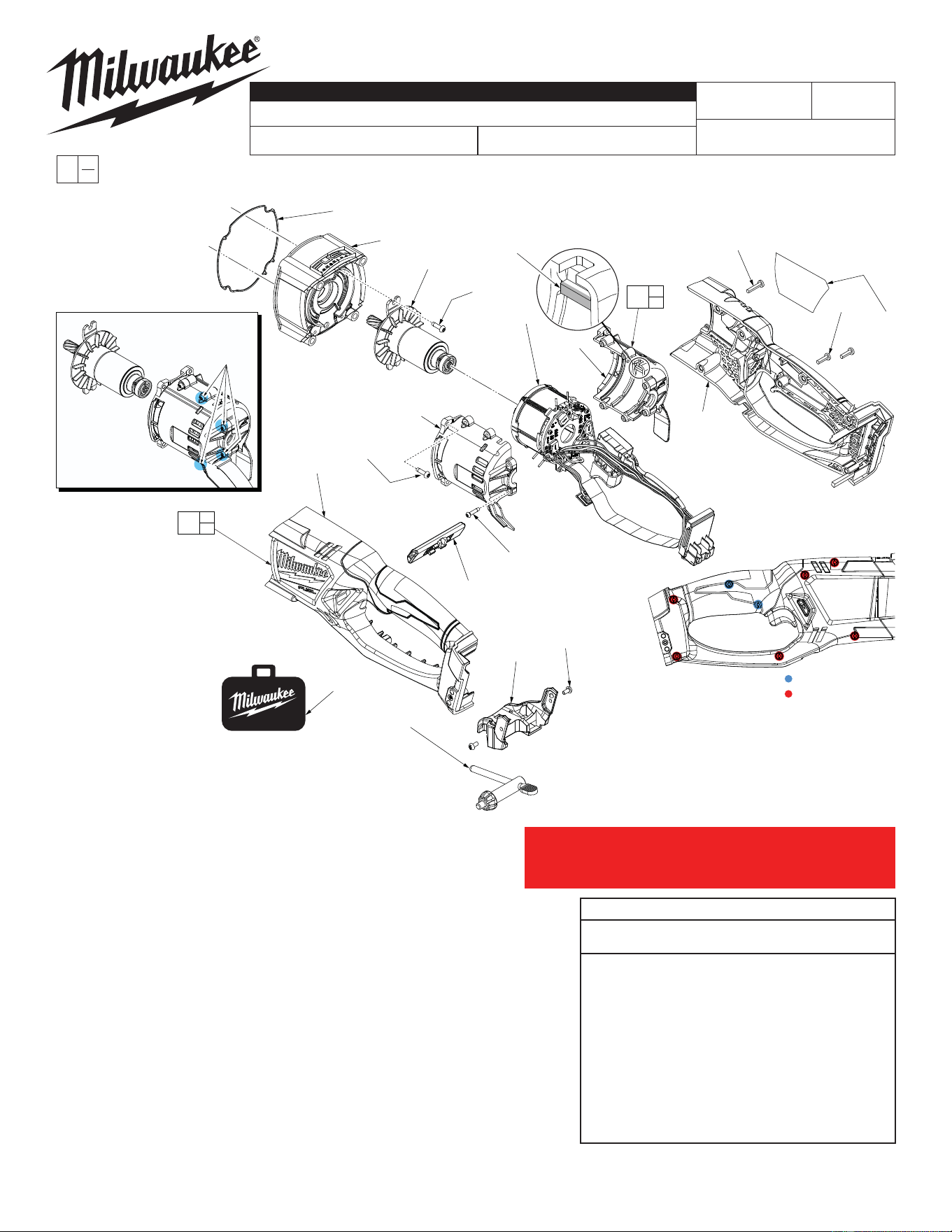
M18™ FUEL™ 1/2" Super-Hawg
®
2709-20
G60A
54-10-2720
SEE PAGE 4
July 2015
FIG. PART NO. DESCRIPTION OF PART NO. REQ.
16 06-82-7261 6-19 x .687 Pan Hd. Slt. Plast. T-15 Screw (6)
50 43-44-0705 Gasket (1)
61 06-82-5314 10-24 x 1/2" Pan Hd. Tapt. T-25 Screw (2)
68 06-82-7240 6-19 x .5 Pan Hd. Slt. Plast. T-15 Screw (2)
69 12-20-0077 Service Nameplate (1)
70 --------------- Right Handle Halve (Cover) (1)
72 45-30-1000 Rubber Slug (2)
73 --------------- Left Handle Halve (Support) (1)
74 42-42-0017 Forward/Reverse Shuttle (1)
75 06-82-5285 6-32 x .5 Pan Hd. Tapt. T-15 Screw (4)
76 06-82-1080 M3 x 14mm T-10 ST Screw (6)
77 --------------- Motor Cage Cover - Left (1)
78 --------------- Motor Cage Support - Right (1)
79 06-82-0130 6-32 x 5/16" Pan Hd. T-15 Machine Screw (2)
82 48-66-3280 Chuck Key (1)
94 23-16-0205 Motor Cage Assembly (1)
96 31-44-1095 Handle Assembly (1)
97 14-20-2709 Electronics Assembly
Contains: Stator, PCBA, On-Off Switch,
LED, Battery Connector Block (1)
98 16-01-2709 Rotor Assembly (1)
99 14-13-0055 Diaphragm Assembly with Needle Bearings (1)
100 43-72-0077 Key Holder Assembly (1)
105 42-55-3565 FUEL™ Contractor Bag - Large (1)
REVISED BULLETIN
SERVICE PARTS LIST
BULLETIN NO.
WIRING INSTRUCTION
DATE
SPECIFY CATALOG NO. AND SERIAL NO. WHEN ORDERING PARTS
CATALOG NO.
MILWAUKEE TOOL
www.milwaukeetool.com
13135 W. LISBON RD., BROOKFIELD, WI 53005
Drwg. 1
STARTING
SERIAL NO.
EXAMPLE:
Component Parts (Small #) Are Included
When Ordering The Assembly (Large #).
0
00
IMPORTANT!
To prevent damage to the High Voltage Wire Assembly, a com-
ponent in the Electronics Assembly #97, see service note on
page 4 prior to removing the Motor Cage Cover #77.
= #68, 06-82-7240
= #16, 06-82-7261
75
(4x)
77
73
74
76
(6x)
100
79
(2x)
82
105
50
99
98
61
(2x)
97
78
70
68
(2x)
69
16
(6x)
77
78
94
70
73
96
NOTE: As an aid when
installing Rotor, loosen
four rear screws on the
Motor Cage Assy.
Slide Rotor into
Stator and firm-
ly seat rear ball
bearing in motor
cage cavity. Retighten
the four screws.
Both motor cage halves have a
raised rib that is to be firmly
seated into slots on each
side of the stator
assembly.
SCREW TORQUE CHART
Seat Torque
Item Part Number (Kg./cm.) (In./lbs.)
1 06-75-3155 140-160 122-139
4 06-82-5411 35-50 30-43
15 05-88-9915 60-65 52-56
16 06-82-7261 For Shift Hub 8-12 7-10
16 06-82-7261 For Handle 12-17 10-14
24 05-88-0510 30-45 26-39
30 06-82-5360 75-86 65-74
61 06-82-5314 46-58 40-50
68 06-82-7240 12-17 10-14
75 06-82-5285 12-17 10-14
76 06-82-1080 7-13 6-11
79 06-82-0130 10-15 8-13
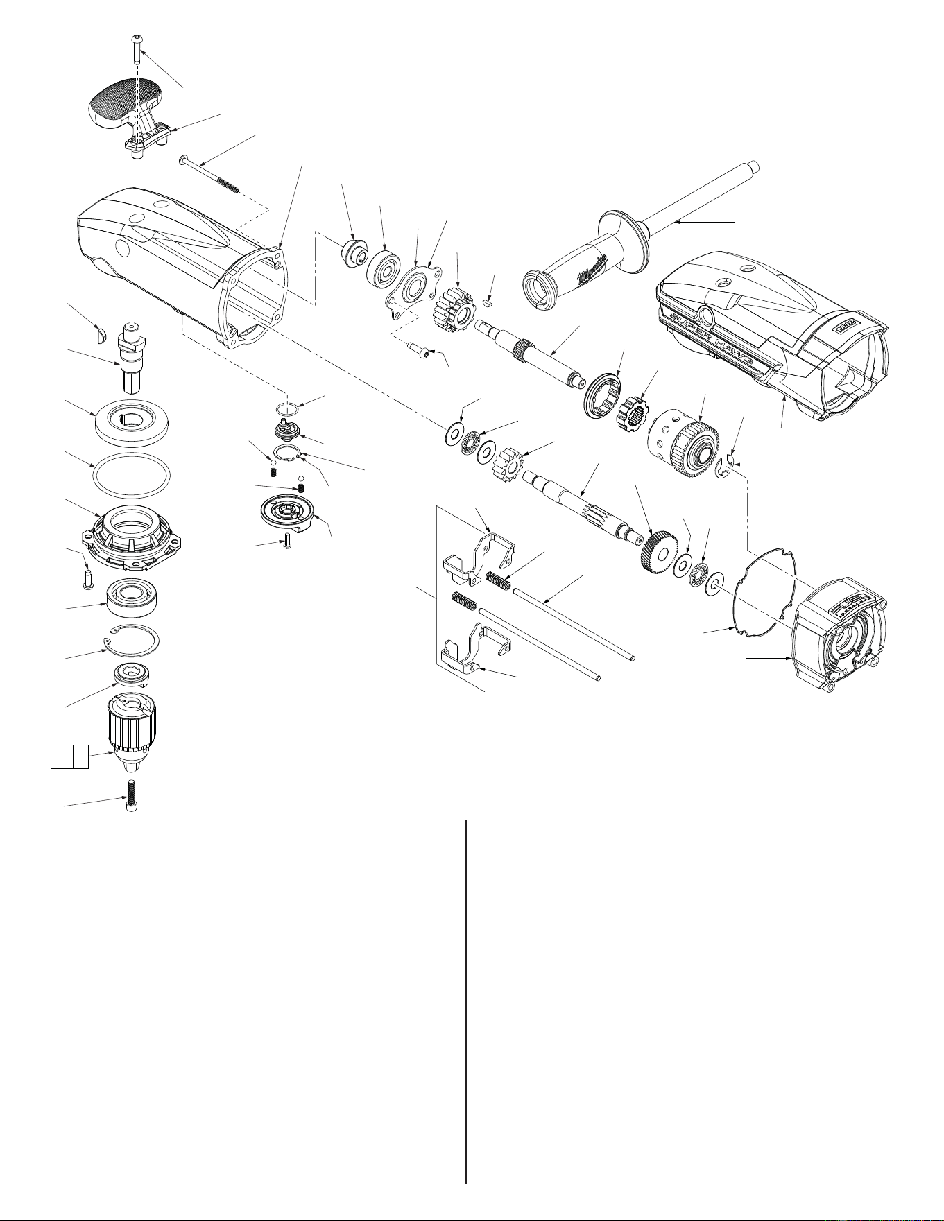
See page three for
assembly details
‘Bearing Side’
stamped on part
Secure Top Handle (14) to the Gear
Case (93) with two Screws (15) only
after Insulated Boot (13) is installed.
24
(4x)
15
(2x)
14
93
27
28
29
31
32
33
34
35
95
43
13
10
11
9
8
7
4
(4x)
6
5
3
1
22
21
20
17
19
(2x)
18
(2x)
16
45
(2x)
47
48
49
30
(2x)
45
(2x)
46
46
54
(2x)
55
(2x)
50
99
53
52
92
1
82
2
Flat side towards
Clutch Hub
Assembly (95)
Flat side down
towards tool
FIG. PART NO. DESCRIPTION OF PART NO. REQ.
1 06-75-3155 1/4-20 x 1" Socket Head Screw-LH Thread (1)
2 48-66-1481 1/2" Keyed Chuck with Chuck Key & Screw (1)
3 28-53-0115 Chuck Hub (1)
4 06-82-5411 10-24 x .625 Pan Hd. Taptite T-25 Screw (4)
5 34-80-2980 Retaining Ring (1)
6 02-04-2031 Ball Bearing (1)
7 28-53-0095 Spindle Mounting Hub (1)
8 34-40-0005 O-Ring (1)
9 32-05-0400 Bevel Gear (1)
10 06-42-2400 Woodruff Key (1)
11 38-50-0027 Spindle (1)
13 45-12-0044 Insulated Boot (1)
14 31-44-2709 Top Handle (1)
15 05-88-9915 M5 x 1.23 x 25mm Pan Hd. DG T-25 Screw (2)
16 06-82-7261 6-19 x .687 Pan Hd. Slt. Plast. T-15 Screw (1)
17 43-98-0067 Shifting Knob (1)
18 40-50-8690 Detent Spring (2)
19 02-02-1300 Steel Ball (2)
20 44-86-0032 Retaining Ring (1)
21 28-53-0085 Shifting Hub (1)
22 34-40-1570 O-Ring (1)
24 05-88-0510 M5 x 80mm Pan Hd. T-20 PT Screw (4)
27 32-60-0280 Bevel Pinion (1)
28 02-04-1055 Ball Bearing (1)
FIG. PART NO. DESCRIPTION OF PART NO. REQ.
29 44-66-1005 Bearing Retaining Plate (1)
30 06-82-5360 1/4-20 x .625 Pan Hd. Taptite T-30 Screw (2)
31 32-44-0500 2nd Intermediate Gear Assembly - High (1)
32 06-42-0800 Woodruff Key (1)
33 36-66-0300 2nd Intermediate Shaft (1)
34 42-90-0015 Shifting Ring (1)
35 43-12-0065 Drive Hub (1)
43 34-60-1450 E-Ring (1)
45 45-88-0395 Thrust Washer (4)
46 02-80-0180 Thrust Bearing (2)
47 32-60-0405 2nd Intermediate Pinion - High (1)
48 32-60-0400 2nd Intermediate Shaft (1)
49 32-42-0200 1st Intermediate Gear (1)
50 43-44-0705 Gasket (1)
52 42-76-0281 Short Shift (1)
53 42-76-0271 Long Shift (1)
54 40-50-0067 Shifter Spring (2)
55 44-94-0012 Shifting Rod (2)
92 14-34-0030 Side Handle Assembly (1)
93 14-30-0505 Gearcase Assembly with Needle Bearings (1)
95 14-08-2709 Clutch Hub Assembly (1)
99 14-13-0055 Diaphragm Assembly with Needle Bearings (1)
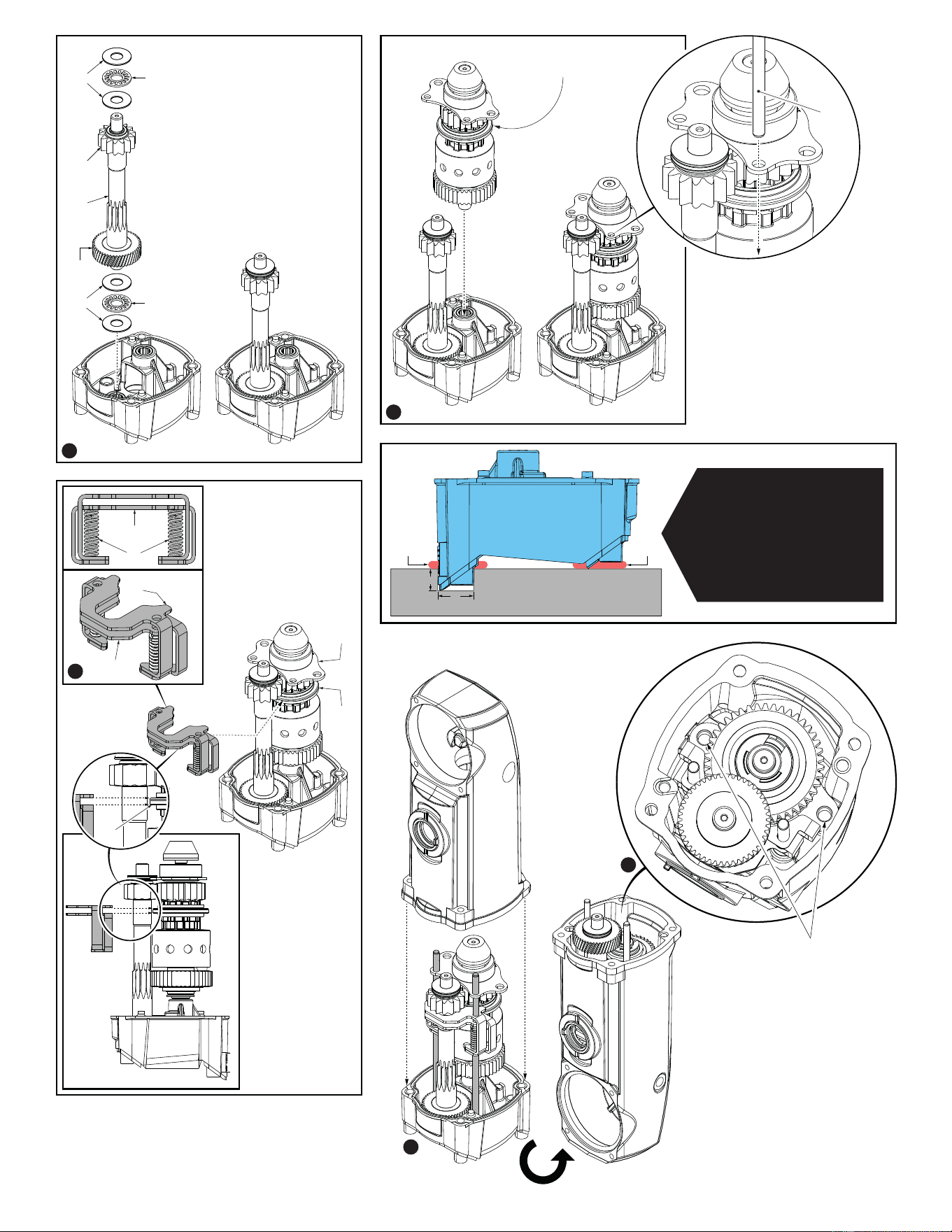
Extra/Old Diaphragm
(with needle bearings)
.75”
Mounting Base
(Approx. 6” x 6” x 1”)
.5”
Epoxy Epoxy
As an aid to reinstalling the
gearing/clutch mechanism
into a FUEL™ Super-Hawg
®
,
a fixture can be made with
an old used diaphragm (with
the needle bearings) and a
piece of mounting stock such
as a piece of wood. A fixture
such as this will free both
hands for assembling.
45
47
48
49
46
45
46
1. Use Type ‘Y’ Grease,
No. 49-08-5275 to lubricate
parts 45, 46, 47, 48, 49 and
assemble together. Install
onto the diaphragm service
fixture as shown.
DIAPHRAGM
SVC FIXTURE
2
1
3
4
5
2. Use Type ‘Y’ Grease, No. 49-08-
5275 to lubricate parts 27, 28, 29,
31, 32, 33, 35 and 95. Assemble
together and contain with E-Ring
43. Install onto the diaphragm
service fixture as shown. Use a
Shifting Rod, 55 to properly align
the holes in the Bearing
Retaining Plate with the holes in
the service fixture. Remove the
Shifting Rod.
Parts 27, 28, 29, 31, 32, 33,
34, 35, 95 and 43.
55
54
52
53
53
3. Use Type ‘Y’ Grease,
No. 49-08-5275 to
lubricate parts 52, 53
and 54. Assemble parts
together as shown.
Install onto Shifting
Ring 34, lining up the
Shifting Rod holes of
29, 52 and 53.
29
34
34
5. Secure gear/clutch mechanism
into Gearcase Assembly (93) by
using a long T-30 bit to drive two
06-82-5360 Screws.
4. Carefully feed both Shifting Rods through the holes in the
Bearing Retaining Plate and the Long and Short Shift
Plates down into the corresponding holes in the service
fixture. Carefully place the Gearcase Assembly over the
gearing and onto the service fixture. Turn the assembly
over and remove the diaphragm service fixture.
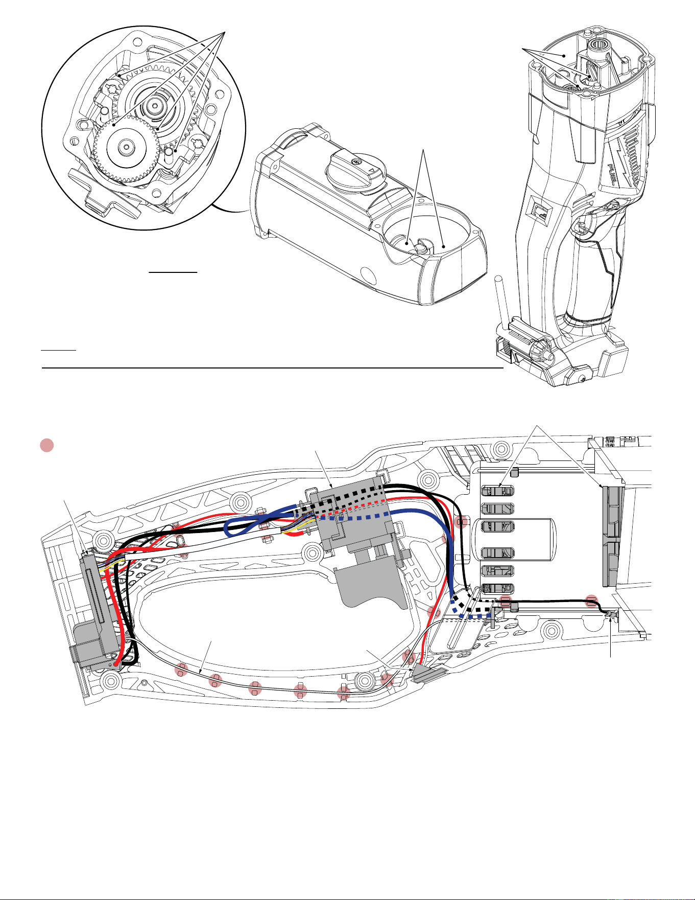
AS AN AID TO REASSEMBLY, TAKE NOTICE OF WIRE ROUTING AND POSITION
IN WIRE GUIDES AND TRAPS WHILE DISMANTLING TOOL.
BE SURE THAT ALL COMPONENTS OF THE ELECTRONICS KIT ARE SEATED
FIRMLY AND SQUARELY IN THE HANDLE RECESSES.
AVOID PINCHED WIRES, BE SURE THAT ALL WIRES AND SLEEVES ARE
PRESSED COMPLETELY DOWN IN WIRE GUIDES AND TRAPS.
PRIOR TO INSTALLING THE HANDLE COVER ONTO THE HANDLE SUPPORT,
BE SURE THAT THERE ARE NO INTERFERENCES.
Place approximately 8.11 ounces
(230 grams) of ‘Y’ Grease down
and around the gear and clutch
mechanism inside the gear case.
Place approximately 1.76 ounces
(50 grams) of ‘Y’ Grease around
the bevel pinion and bevel gear
cavity of the gear case.
Place approximately 2.11 ounces
(60 grams) of ‘Y’ Grease into
this area of the diaphragm
assembly.
LUBRICATION NOTES:
Type ‘Y’ Grease No. 49-08-5270, 6oz./170g tube
The entire amount of two tubes will be needed.
or
Type ‘Y’ Grease No. 49-08-5275, 14oz./396g tub (can)
When servicing, remove 90-95% of the existing grease prior to installing Type 'Y'.
Original grease may be similar in color but not compatible with 'Y'.
DO NOT wash Clutch Hub Assembly #95. Prior to reinstalling, clean gear assemblies with a clean, dry cloth.
NOTE:
Disconnect/unscrew the High Voltage Wire
from the Diaphragm and remove wire from
traps prior to removing Electronics Assembly.
Battery
Connector
Block
On-Off Switch
Inside Motor Cage Assembly:
Rotor, Stator and PCBA
High Voltage Wire
(Ground Terminal)
LED
Assembly
Ribbon Cable
= WIRE TRAPS
or GUIDES
WIRING DIAGRAM