© 2020 AMETEK Electronic Systems Protection / Technical Support: 1-800-645-9721 / UM-Security-Plus-II-Rev-A
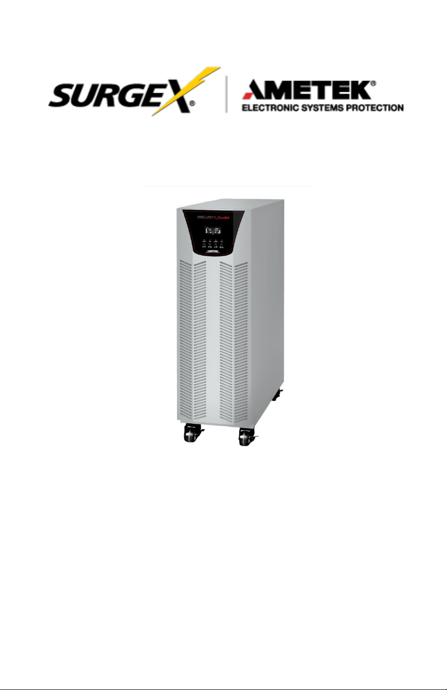
Security Plus II
Online Uninterruptible Power Supply
UPS-42100-85R
User Manual
User Manual
_________________________________________________________
© 2020 AMETEK Electronic Systems Protection / Technical Support: 1-800-645-9721 / ametekesp.com

User Manual
_________________________________________________________
© 2020 AMETEK Electronic Systems Protection / Technical Support: 1-800-645-9721 / ametekesp.com
TABLE OF CONTENTS
1.0 GENERAL SAFETY INSTRUCTIONS 1
2.0 UNPACKING AND INSPECTION 6
3.0 UPS PANEL LA
YOUT
7
4.0 UPS INSTALLATION (Hardwire Units Only) 8
4.1 Overview
8
4.2 Wiring Diagrams 10
4.3 Circuit Protection Requirements 14
5.0 OPERATION 16
5.1 Button Operation
16
5.2 LED Indicators and LCD Panel 17
5.3 Audible Alarm
19
5.4 Single UPS Operation
20
5.5 Connect Devices to UPS 21
5.6 Charge the Batteries 21
5.7 Battery Mode Operation 22
5.8 Test the Batteries 22
5.9 Turn Off the UPS with Utility Power Supply in AC Mode 22
5.10 Turn Off the UPS Without Utility Power Supply in Battery Mode 23
5.11 Mute the Buzzer 23
5.12 Operation in Warning Status 23
5.13 Operation in Fault Mode 24
5.14 Operation of Changing Charging Current 24
6.0 LCD SETTING 25
7.0 OPERATON MODE/STATUS DESCRIPTION 34
8.0 FAULT CODE
36
8.1 Warning Indicator 36
8.2 Warning Code 37
9.0.
TROUBLESHOOTING
38
10.0. STORAGE AND MAINTENANCE 40
10.1 Storage 40
10.2 Maintenance 40
1
User Manual
_________________________________________________________
© 2020 AMETEK Electronic Systems Protection / Technical Support: 1-800-645-9721 / ametekesp.com
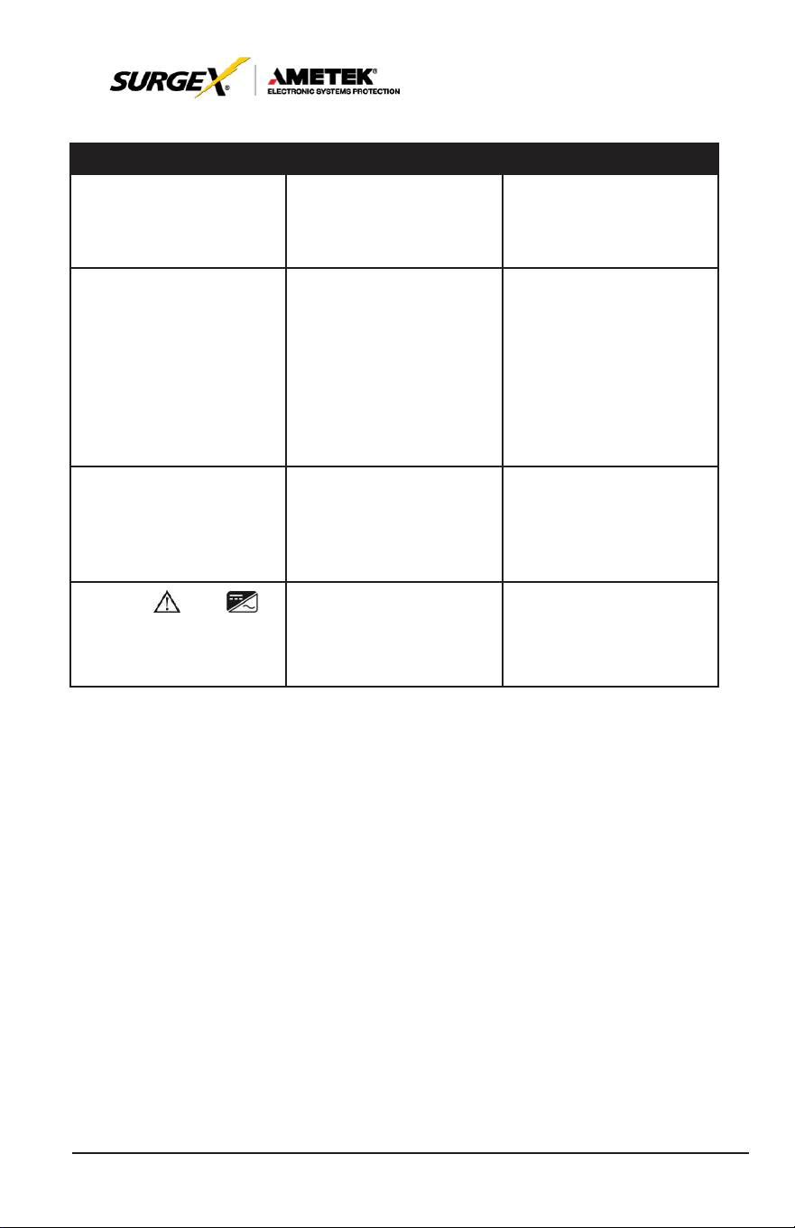
1.0 GENERAL SAFETY INSTRUCTIONS
Warnings in this manual appear in any of four ways:
Use of this equipment in life support applications where failure of this
equipment can reasonably be expected to cause the failure of the life
support equipment
or to significantly affect its safety or
ef
fectiveness
is not recommended. Do not use this equipment in the presence of a
flammable
anesthetic
mixture with air, oxygen or nitrous
oxide.
Connect
your UPS power
module’s grounding
terminal to a
grounding
electrode conductor.
The UPS is connected to a DC energy source (battery). The output
terminals may be live when the UPS is not connected to an AC supply.
Operation
DAN
GE
R
Do not disconnect the earth conductor cable on the
UPS
or the building
wiring terminals at any time as this would negate the protective earth of the
UPS
system and of all connected loads.
DAN
GE
R
The
UPS
system features its own, internal current source (batteries). The
UPS
output sockets or output terminal blocks may be electrically live even if
the
UPS
system is not connected to the building wiring outlet.
W
ARN
ING
In order to fully
disconnect
the UPS
system,
first
press
the “OFF” button
and
then disconnect the mains.

2
User Manual
_________________________________________________________
© 2020 AMETEK Electronic Systems Protection / Technical Support: 1-800-645-9721 / ametekesp.com
NOTE TO USERS
To ensure correct operation of the UPS, please read this instruction
manual carefully. Please keep this manual handy for future reference.
ELECTRICAL HAZARD
AUTHORIZED
PERSONNEL
ONLY
This UPS has dangerously high voltages on both its Input
and output connections. Contact with these voltages may
be life threatening. Please follow the operating instructions
carefully. Please give close attention to the warnings in
this manual and those posted on the UPS. There are no
user serviceable parts inside the UPS. Disassembly and/
or maintenance should only be done by an authorized
professional service technician
IMPORTANT INFORMATION FOR USERS
OF
THIS UNINTERRUPTIBLE POWER
SUPPLY
1. Before operating the UPS or connecting any load equipment,
please ensure the UPS is connected to a properly grounded
electrical supply.
2. This UPS has dangerously high voltages on both its input and
output connections. Contact with these voltages may be life
threatening.
3. Please do not disassemble the covers. There is a risk of electric
shock.
4. In an emergency, immediately turn off the circuit breaker for the
circuit supplying power to the UPS; open DC on battery breaker.
5. This UPS has two power sources. One is the circuit supplying the
UPS with input power. The other is the UPS battery. Prior to any
maintenance, both of these power sources must be disconnected
to ensure that the UPS is de-energized. If only the input power
is disconnected, the UPS can still operate from the battery, and
hazardous voltages may still exist.
6. To prevent damage or a safety hazard, keep the UPS away from
open flame and any other
devices
that may
cause sparks.
7. Do not open or damage individual battery cases as spillage of

3
User Manual
_________________________________________________________
© 2020 AMETEK Electronic Systems Protection / Technical Support: 1-800-645-9721 / ametekesp.com
caustic electrolyte may occur, resulting in danger to life, safety, and
the environment.
8. The charging characteristics of UPS batteries vary by both brand
and type. For this reason, replacement batteries should be of the
same
brand and type
as those specified
by the
manufacturer
.
Using
batteries
other than the brand and
type
specified
by
the
manufacturer may affect the performance
of the UPS. Before installing batteries of different brand or type,
please consult with the manufacturer.
9. The UPS has an internal EMI filter for
purposes
of
enhancing
electromagnetic compatibility with the input mains
supply. This filter
produces leakage
current to earth on the
input mains.
When
selecting a circuit breaker for the branch
circuit supplying power
to the UPS, ensure that the breaker selected is not an ELCB type
circuit breaker that detects earth leakage current.
10. Please contact the manufacturer or an authorized distributor for
any assistance with troubleshooting.
11. The UPS should only be serviced or maintained by a factory
authorized service technician.
12. This UPS meets FCC Class A electromagnetic compatibility
requirements.
13. Depleted batteries must be disposed of in a proper manner
.
Contact your local recycling or hazardous waste center or the UPS
manufacturer for instructions concerning proper disposal.
CAU
TION
Please be careful to observe the following general safety precautions
during operation or maintenance
1. There are no user serviceable parts inside this UPS. Please don’t
remove
the
covers.
This
system
can only be
maintained or
repaired by an authorized SurgeX service technician.

4
User Manual
_________________________________________________________
© 2020 AMETEK Electronic Systems Protection / Technical Support: 1-800-645-9721 / ametekesp.com
2. To improve electromagnetic compatibility (EMC), this UPS has
an input EMI filter, which
produces
potentially
dangerous
leakage
current to ground. Ensure the UPS is connected to a
properly grounded input electrical source. Install this UPS indoors
in an environment that is temperature and humidity controlled.
3. Install this UPS in a dust-free environment.
4. This UPS has two sources of power. Before maintenance is
performed, turn off the branch circuit breaker powering the UPS
and turn off all battery switches.
5. Even with the AC input power supply turned off, the
UPS’s
internal
battery still represents a potentially dangerous source of
high voltage electrical power.
6. If the battery circuit has not been disconnected from the AC
input, dangerous voltage potential still exists between the battery
terminal and the ground terminal.
7. UPS batteries represent a high voltage source and a potential
hazard to personal safety. Please pay attention to proper safety
precautions and use insulated tools during installation.
8. UPS batteries contain corrosive and caustic chemicals. Improper
handling of batteries may lead to the unintended release or
leakage of these substances. Please handle batteries carefully.
9. Condensation may occur when the UPS is moved from a
low temperature, low humidity environment to a warm humid
environment. Condensation may cause UPS damage or hazardous
electrical shock. To ensure the safety of both the UPS and the
personnel around it, make sure that the UPS is installed only after
it has fully acclimated to its installation environment. This UPS
is not intended to be operated in an environment of either low
temperature or high humidity.
10. The DC voltage is still present on the battery fuses even with the
UPS turned off. The batteries must be removed before servicing
UPS.
5
User Manual
_________________________________________________________
© 2020 AMETEK Electronic Systems Protection / Technical Support: 1-800-645-9721 / ametekesp.com
CAU
TION
Ensure that no liquid or other foreign objects can enter into the
UPS
system.
W
ARN
ING
The
UPS
is to be operated by individuals with appropriate experience.
Standards* Safety
Safety Conformance:
IEC/EN
62040-1, UL1778 (5th Edition)
Safety Markings: cTUVus, CE
* EMI
Conducted
Emission: IEC/EN
62040-2,
FCC PART15 CLASS A
Radiated
Emission: IEC/EN
62040-2,
FCC PART15 CLASS A
*EMS
ESD: IEC/EN
61000-4-2
Level 4
RS: IEC/EN
61000-4-3
Level
3
EFT: IEC/EN
61000-4-4
Level 4
SURGE: IEC/EN
61000-4-5
Level 4
CS:
IEC/EN
61000-4-6
Level
3
Power-frequency Magnetic
field: IEC/EN
61000-4-8
Level 4
Low
Frequency Signals:
IEC/EN
61000-2-2
Warning: This is a product for commercial and industrial application in the
second environment installation restrictions or additional measures may be
needed to prevent disturbances.

6
User Manual
_________________________________________________________
© 2020 AMETEK Electronic Systems Protection / Technical Support: 1-800-645-9721 / ametekesp.com
2.0 UNPACKING AND INSPECTION
Unpack the package and check the contents. The shipping package
contains:
• Quick Start Guide
• One UPS
• One RS-232 cable (option)
• One USB cable
NOTE:
Before installation, please inspect the unit. Be sure that nothing
inside the package is damaged during transportation. Do not
turn on the unit and notify the carrier and dealer immediately
if there is any damage or lacking some parts. Please keep the
original package in a safe place for future use.
7
User Manual
_________________________________________________________
© 2020 AMETEK Electronic Systems Protection / Technical Support: 1-800-645-9721 / ametekesp.com
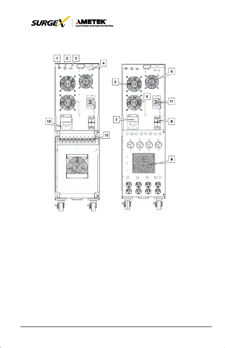
3.0 UPS PANEL
L
A
YOUT
1. RS-232 communications port
2. USB communications port
3. Emergency power off connector (EPO)
4. Intelligent pocket
5. Charger cooling fan
6. Power stage cooling fan
7. Maintenance bypass switch
8. Input circuit breaker
9. Isolation transformer cooling fan
10. Input / output terminal block connections
11. External battery cabinet connection
8
User Manual
_________________________________________________________
© 2020 AMETEK Electronic Systems Protection / Technical Support: 1-800-645-9721 / ametekesp.com
4.0 UPS INSTALLATION (Hardwired units only)
4.1 Overview
CAU
TION
Installation and wiring must be performed in accordance with local electrical
laws/regulations/codes. The following instructions should only be executed
by
qualified
professional
personnel.
1. Make sure the mains wire and breakers in the building are suitable
for the rated capacity of the UPS to avoid the hazards of electric
shock or fire.
2. Switch off mains power before installation.
3. Turn off all the connected devices before connecting to the UPS.
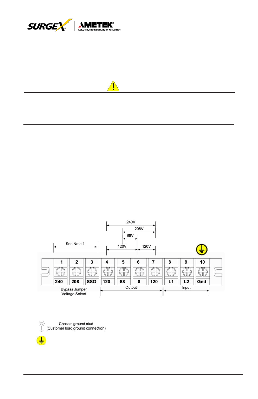
4. Remove terminal block cover on the rear panel of UPS, then
connect the wires according to the following terminal block
diagrams:
Rear panel terminal block layout – all
models
Note: Illustration above showing 10-pole block applies to all
models.
9
User Manual
_________________________________________________________
© 2020 AMETEK Electronic Systems Protection / Technical Support: 1-800-645-9721 / ametekesp.com
• 1 - 3 are SSO TAP selection (must match mains input / inv
voltage selection)
• 4; 5; 6; 7 Next four are outputs as listed -120; 88; 0; +120
• 8; 9; 10 Last three are mains power input l1; l2; earth.
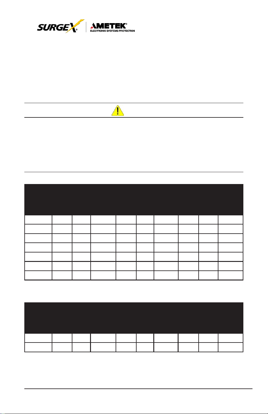
CAU
TION
For field wired units, refer to the
tables
below for the
proper cond
uctor
size
and
torque requirements.
Only
copper conductors
are to be
used
for field
wiring
connections.
The
conductors should
be
rated
at least
75°C or
greater. The conductor recommendations listed in the chart below are
intended
for
installations
in North America. For
international insta
llations, please refer to
the local and national electrical codes and standards.
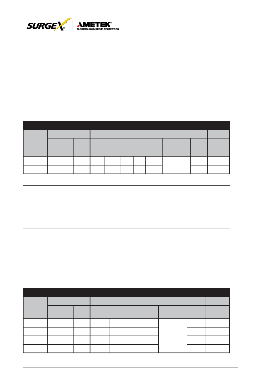
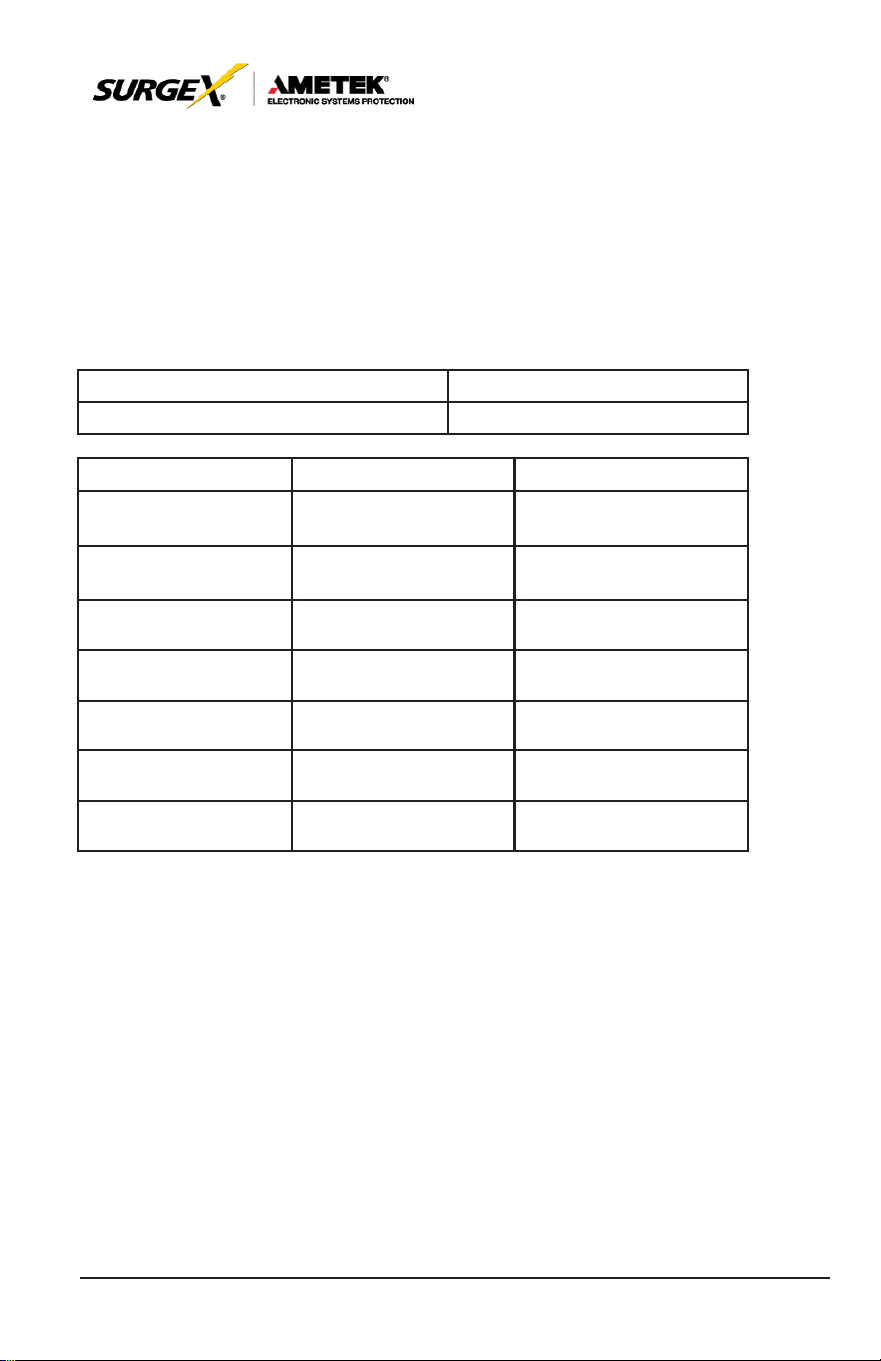
RATING
INPUT
CONDUCTOR
(A
WG)
MIN
MAX
TORQUE
(in-lbs.)
OUTPUT
CONDUCTOR
(A
WG)
MIN
MAX
TORQUE
(in-lbs.)
GROUND
(A
WG)
MIN
MAX
TORQUE
(in-lbs.)
2.0kVA 12 6 20 12 6 20 12 6 20
3.0kVA 12 6 20 12 6 20 12 6 20
4.0kVA 10 6 20 10 6 20 8 6 20
5.2kVA 8 6 20 8 6 20 8 6 20
6.0kVA 8 6 20 8 6 20 6 6 20
8.0kVA 4 1 60 4 1 60 6 4 60
10.0kVA 4 1 60 4 1 60 6 4 60
TABLE 2-4A HIGH VOLTAGE CONDUCTOR SIZE AND TORQUE SPECIFICATIONS
RATING
INPUT
CONDUCTOR
(A
WG)
MIN
MAX
TORQUE
(in-lbs.)
OUTPUT
CONDUCTOR
(A
WG)
MIN
MAX
TORQUE
(in-lbs.)
GROUND
(A
WG)
MIN
MAX
TORQUE
(in-lbs.)
2.0kVA 10 6 20 10 6 20 8 6 20
3.0kVA 8 6 20 8 6 20 6 4 20
TABLE 2-4B LOW VOLTAGE CONDUCTOR SIZE AND TORQUE SPECIFICATIONS
10
User Manual
_________________________________________________________
© 2020 AMETEK Electronic Systems Protection / Technical Support: 1-800-645-9721 / ametekesp.com
4.2 Wiring Diagrams (Hardwired units only)
For North American
applications,
UPS
models
may be
configured
for an
input voltage of 208 or 240 volts at 60 Hz. SSO tap must match
customers utility voltage. Output voltages for these models are available
at 120, 208 (using the 120 & 88 taps) and 240 volts at 60 Hz. See the
table below to connect to the terminal block in Figure 2-5D to achieve the
desired
input and output voltage
configurations.
NORTH AMERICAN CONNECTIONS
INPUT OUTPUT
SSO
VOLTAGE
RATING
VOLTAGE
L1 - L2 FREQ VOLTAGE
NEURTRAL
BOND FREQ
TAP
JUMPER
208 208 60 -120 10.0 88 0 +120 SEE
60 208-(0)
240 240 60 -120 8.0 88 0 +120
DIAGRAM
40 240-(0)
NOTE:
The neutral to ground bond connection must be properly
connected
for a 50 or 60 Hz
configuration.
For
international applications,
UPS
models
may be
configured
for
an
input voltage of 220, 230 or 240 volts at 50 Hz. SSO tap must always
be set to 240. Output voltage for these models matches the input voltage
at 50 Hz. See the table below to connect to the terminal block in Figure
2-5B to
achieve
the
desired
input and output voltage
configurations.
INTERNATIONAL CONNECTIONS
INPUT OUTPUT
VOLTAGE
RATING
VOLTAGE
L1 - L2 FREQ VOLTAGE
NEURTRAL
BOND FREQ
SSO TAP
JUMPER
-- -- -- -- -- -- --
220 220 50Hz 0 -- 110 220
230 230 50Hz 0 -- 115
230
SEE
DIAGRAM
-- --
50Hz 240-(0)
50Hz 240-(0)
240 240 50Hz 0 -- 120 240 50Hz 240-(0)
11
User Manual
_________________________________________________________
© 2020 AMETEK Electronic Systems Protection / Technical Support: 1-800-645-9721 / ametekesp.com
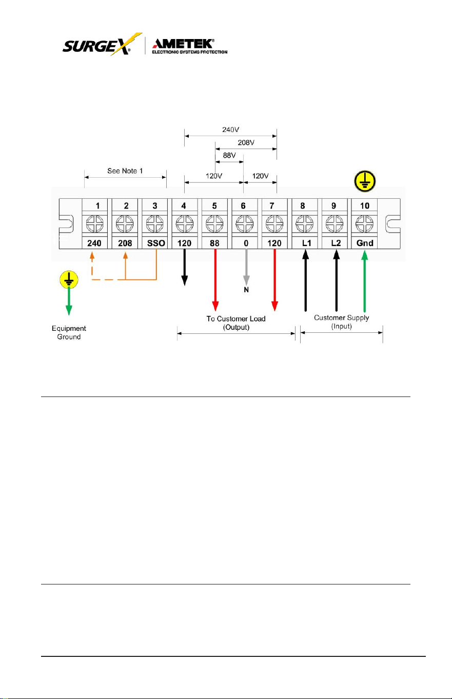
1) 120V and 208V Output
Output wiring – 208V & 120V
NOTE 1: SSO Tap
Selection needs
to be set to
match
the
input
voltage.
NOTE 2: 208 is obtained by using the 120 and 88 terminals.
NOTE 3: Make sure that the wires are connected tightly to the
terminals.
NOTE 4: Install the output breaker between the output terminal and
the load. The
breaker should
be qualified with
leakage
current protection if necessary.
12
User Manual
_________________________________________________________
© 2020 AMETEK Electronic Systems Protection / Technical Support: 1-800-645-9721 / ametekesp.com
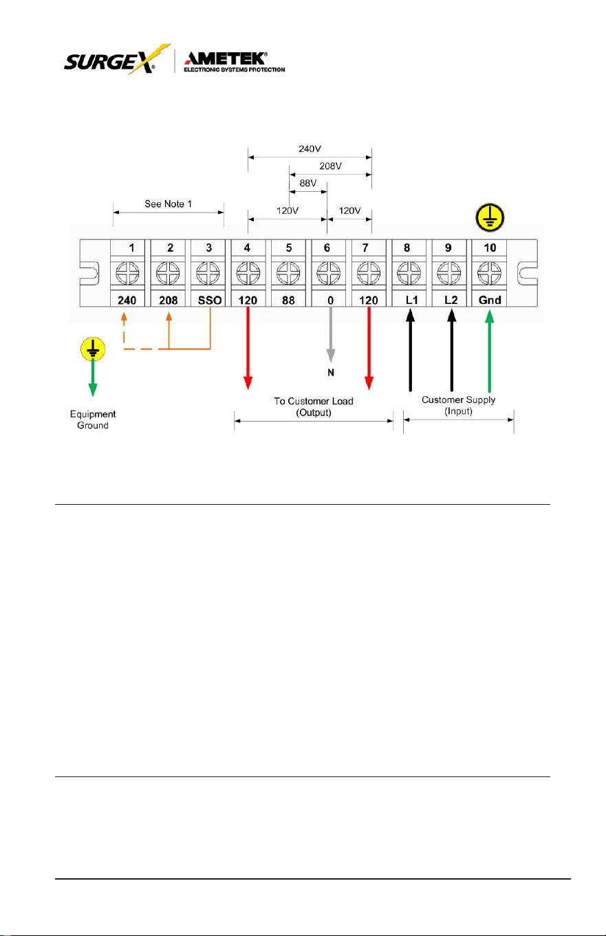
2) 120V and 240V Output
Output wiring – 240V & 120V
NOTE 1: SSO Tap
Selection needs
to be set to
match
the
input
voltage. Install a jumper between 0-208V or 0-240V.
NOTE 2: Split phase wiring, load shall be balanced 50 / 50 on each
side of transformer taps.
NOTE 3: Make sure that the wires are connected tightly to the
terminals.
NOTE 4: Install the output breaker between the output terminal and
the load. The
breaker should
be qualified with
leakage
current protection if necessary.
13
User Manual
_________________________________________________________
© 2020 AMETEK Electronic Systems Protection / Technical Support: 1-800-645-9721 / ametekesp.com
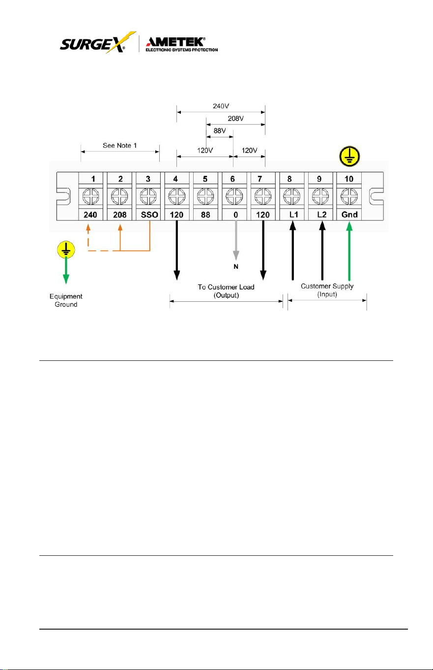
3) 120V Outputs
Output wiring – 120V
NOTE 1: SSO Tap
Selection needs
to be set to
match
the
input
voltage. Install a jumper between 0-208V or 0-240V.
NOTE 2: There are 2 sets of 120V outputs. Each set can carry half
of the total
UPS
capacity.
NOTE 3: Make sure that the wires are connected tightly to the
terminals.
NOTE 4: Install the output breaker between the output terminal and
the load. The
breaker should
be qualified with
leakage
current protection if necessary.
14
User Manual
_________________________________________________________
© 2020 AMETEK Electronic Systems Protection / Technical Support: 1-800-645-9721 / ametekesp.com
4.3 Circuit Protection Requirements (Hardwired units only)
All
SurgeX
Hardwired Security Plus UPS
system’s mains
INPUT
must be protected by proper sized branch circuit breakers in the building
installation. The recommended branch circuit ratings at full rated load are
listed below:
2.0 kVA, Input 120V, Output 100-120V
35 AMP
3.0 kVA, Input 120V, Output 100-120V
45 AMP
Refer to local and national electrical codes for proper installation
guidelines. The breaker recommendations listed in the chart above are
intended for installations in North America. For international installations,
please refer to the local and national electrical codes and standards.
208V
240V
2.0 kVA, Input 208-
240V, Output 200-240V
20
AMP
15
AMP
3.0 kVA, Input 208-
240V, Output 200-240V
25
AMP
20
AMP
4.0 kVA, Input 208-
240V, Output 120-240V
35
AMP
25
AMP
5.0 kVA, Input 208-
240V, Output 120-240V
40
AMP
30
AMP
6.0 kVA, Input 208-
240V, Output 120-240V
45
AMP
35
AMP
8.0 kVA, Input 208-
240V, Output 120-240V
60
AMP
45
AMP
10.0 kVA, Input 208-
240V, Output 120-240V
80
AMP
60
AMP
15
User Manual
_________________________________________________________
© 2020 AMETEK Electronic Systems Protection / Technical Support: 1-800-645-9721 / ametekesp.com
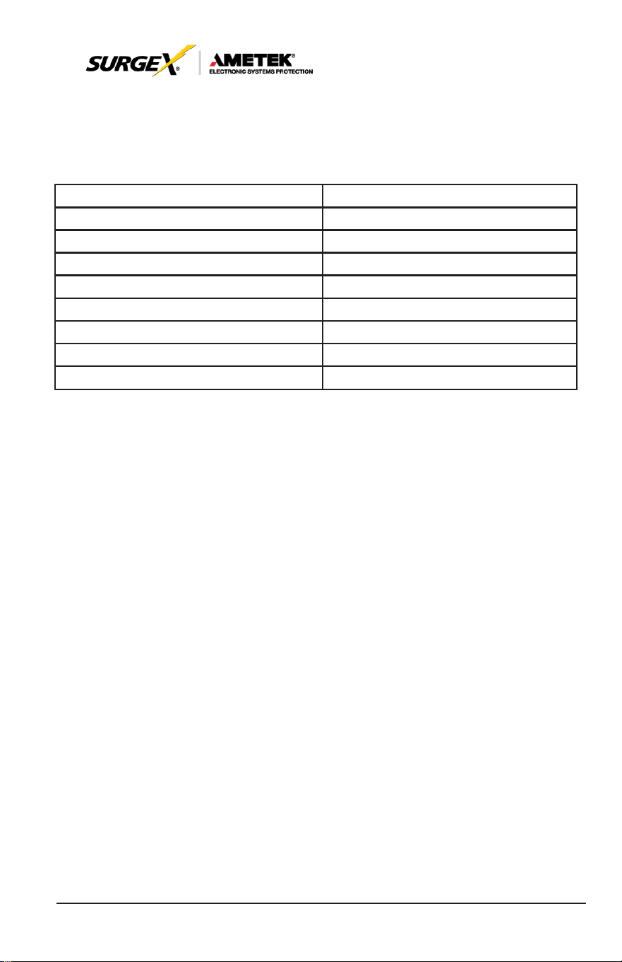
All
SurgeX
Hardwired Security Plus UPS
system’
s
OUTPUT must be
protected by proper sized AC disconnect device. The recommended
disconnect device ratings at full rated load are listed below:
2.0 kVA, Input 120V, Output 100-120V
20
AMP
2.0 kVA, Input 208-240V, Output 200-240V
10
AMP
3.0 kVA, Input 120V, Output 100-120V
30
AMP
3.0 kVA, Input 208-240V, Output 200-240V
15
AMP
4.0 kVA, Input 208-240V, Output 120-240V
20
AMP
5.0 kVA, Input 208-240V, Output 120-240V
25
AMP
6.0 kVA, Input 208-240V, Output 120-240V
30
AMP
8.0 kVA, Input 208-240V, Output 120-240V
50
AMP
10.0 kVA, Input 208-240V, Output 120-240V
65
AMP
16
User Manual
_________________________________________________________
© 2020 AMETEK Electronic Systems Protection / Technical Support: 1-800-645-9721 / ametekesp.com
5.0 OPERATION
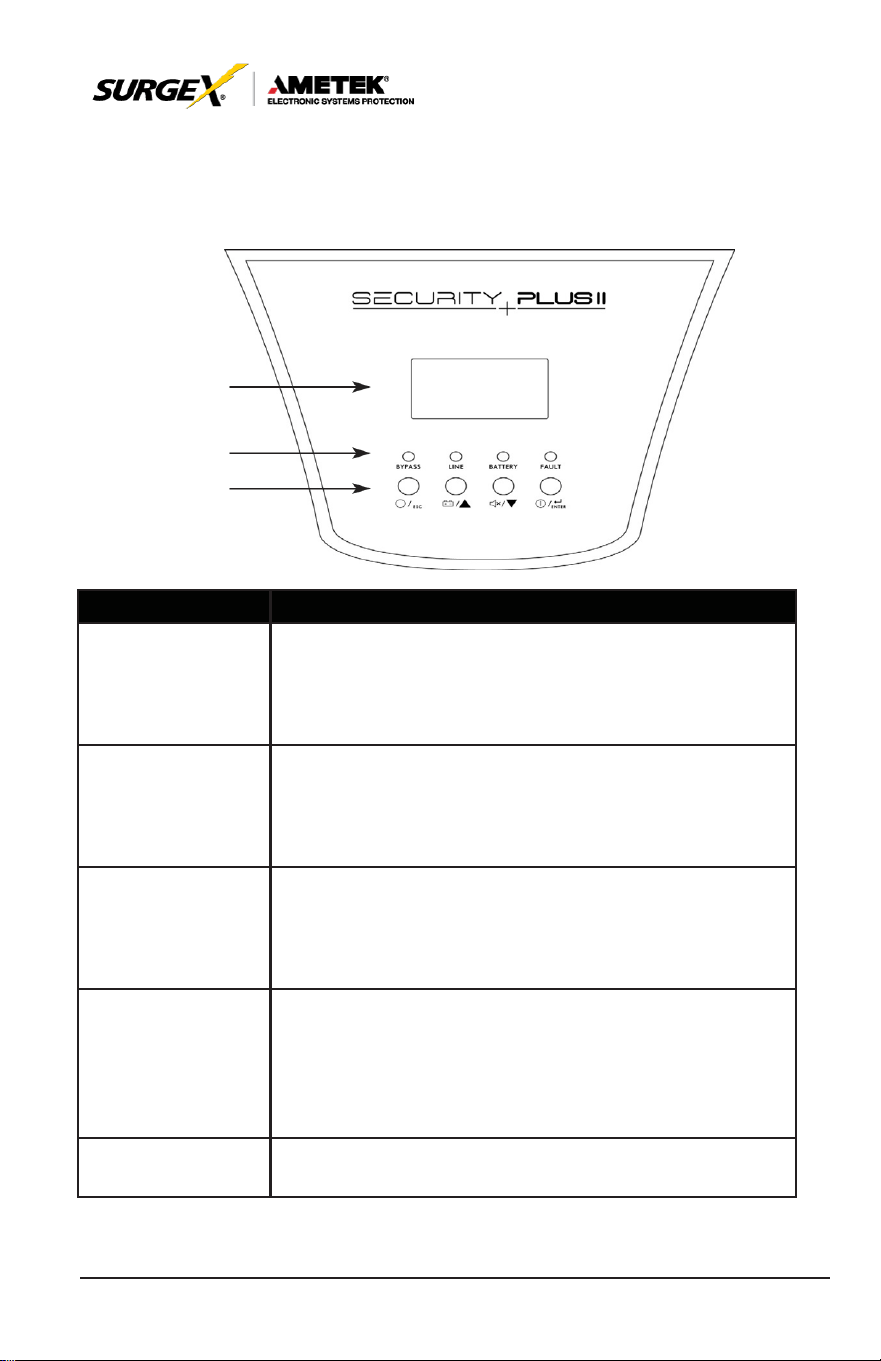
5.1 Button Operation
LCD
LED
Button
Button
Function
ON/Enter
Button
Turn on the
UPS:
Press and hold the button more than
0.5s to turn on the UPS.
Enter Key:
Press
this button to confirm the
selection
in
setting menu.
OFF/ESC
Button
Turn off the
UPS:
Press and hold the button more than
0.5s to turn off the UPS.
Esc key: Press this button to return to last menu in set-
ting menu.
Test/Up Button
Battery test: Press and hold the button more than 0.5s to
test the
battery
while in AC
mode,
or CVCF
mode.
UP key: Press this button to display next selection in
setting menu.
Mute/Down Button
Mute the alarm: Press and hold the button more than
0.5s to mute the
buzzer. Please
refer to
section
3-4-
9 for details.
Down key: Press this button to display previous selec-
tion in setting menu.
Test/Up + Mute/
Down Button
Press and hold the two buttons simultaneous more than
1s to enter/escape the setting menu.
*
CVCF
mode means converter mode.
17
User Manual
_________________________________________________________
© 2020 AMETEK Electronic Systems Protection / Technical Support: 1-800-645-9721 / ametekesp.com
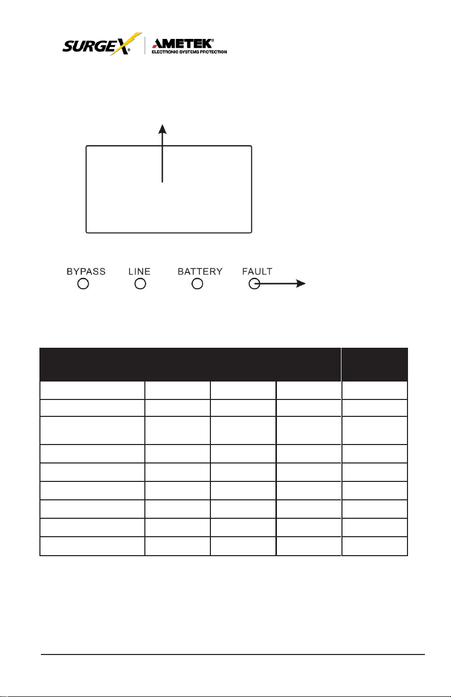
5.2 LED Indicators and LCD Panel
LCD panel
LED indicators
LED Indicators:
There are 4 LEDs on front panel to show the UPS working status:
LED
Mode
Bypass
Line
Battery
Fault
UPS
Startup
●
●
●
●
No Output
mode
○
○
○
○
Bypass mode
●
○
○
○
AC
mode
○
●
○
○
Battery mode
○
○
●
○
CVCF
mode
○
●
○
○
Battery Test
●
●
●
○
ECO
mode
●
●
○
○
Fault
○
○
○
●
Note: ● means LED is lighting, and ○ means LED is faded.
18
User Manual
_________________________________________________________
© 2020 AMETEK Electronic Systems Protection / Technical Support: 1-800-645-9721 / ametekesp.com
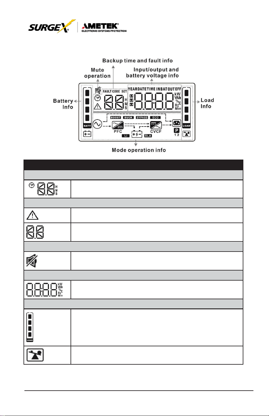
LCD Panel:
Display
Function
Backup Time Information
Indicates battery discharge time in numbers. H: hours, M:
minutes, S: seconds
Fault Information
Indicates that the warning and fault occurs.
Indicates the fault codes, and the codes are listed in detail
in
section 3-9.
Mute Operation
Indicates that the
UPS
alarm is disabled.
Output & Battery voltage information
Indicates the output voltage, frequency or battery voltage.
Vac: output voltage, Vdc: battery voltage, Hz: frequency
Load information
Indicates the load level by 0-25%, 26-50%, 51-75%, and
76-100%.
Indicates overload.
19
User Manual
_________________________________________________________
© 2020 AMETEK Electronic Systems Protection / Technical Support: 1-800-645-9721 / ametekesp.com
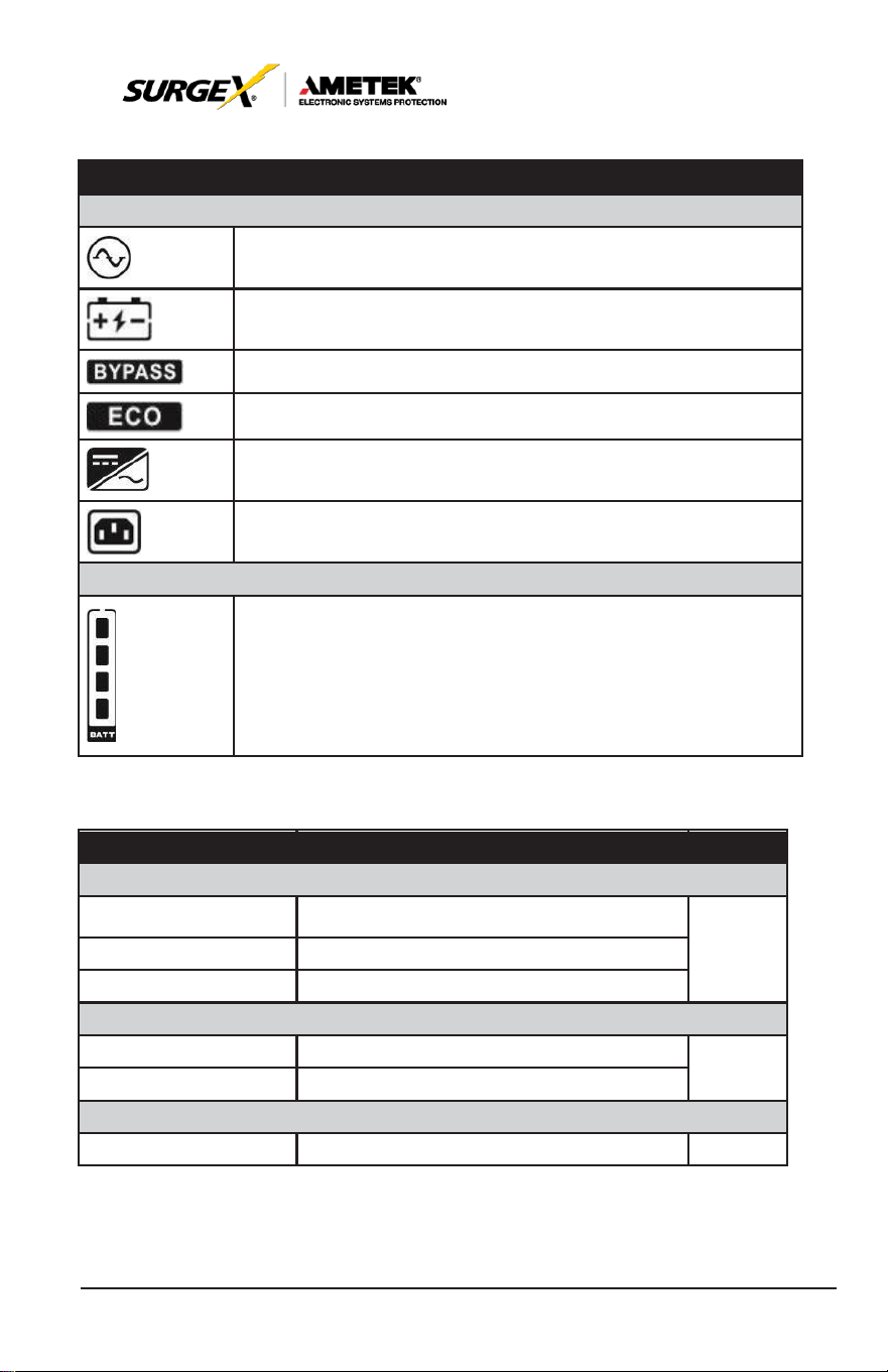
Display
Function
Mode operation information
Indicates the
UPS
connects to the mains.
Indicates the battery is working.
Indicates the bypass circuit is working.
Indicates
the ECO
mode
is
enabled.
Indicates the Inverter circuit is working.
Indicates the output is working.
Battery information
Indicates the Battery capacity by 0-25%, 26-50%, 51-75%,
and 76-100%.
5.3. Audible Alarm
Description
Buzzer status
Muted
UPS status
Bypass mode
Beeping once every 2 minutes
Yes
Battery mode
Beeping once every 4 seconds
Fault
mode
Beeping continuously
Warning
Overload
Beeping twice every second
Yes
Others
Beeping once every second
Fault
All
Beeping continuously
Yes

20
User Manual
_________________________________________________________
© 2020 AMETEK Electronic Systems Protection / Technical Support: 1-800-645-9721 / ametekesp.com
5.4 Single UPS Operation
1. Turn on the UPS with utility power supply (in AC mode)
1. After power supply is connected correctly, set the breaker of the battery
pack at “ON” position (the step only available for long-run model). Then
set the input breaker at “ON” position. At this time the fan is running
and the UPS supplies power to the loads via the bypass. The UPS is
operating in Bypass mode.
NOTE:
When
UPS
is in Bypass mode, the output voltage will directly power
from utility after you switch on the input breaker. In Bypass mode, the
load is not protected by
UPS.
To protect your precious devices, you
should
turn on the UPS. Refer to next
step.
2. Press and hold the “ON” button for 0.5s to turn on the UPS and the
buzzer will beep once.
3. A few seconds later, the UPS will enter to AC mode. If the utility power is
abnormal, the UPS will operate in Battery mode without interruption.
NOTE:
When the
UPS
is running out of battery, it will shut down
automatically at Battery mode. When the utility power is restoring,
the
UPS
will auto restart.
2. Turn on the UPS without utility power supply (in Battery mode)
1. Make sure that the breaker of the battery pack is at “ON” position.
2. Press the “ON” button to set up the power supply for the UPS, UPS will
enter to power on mode. After initialization UPS will enter to No Output
mode, then Press and hold the “ON” button for 0.5s to turn on the UPS,
and the buzzer will beep once.
3. A few seconds later, the UPS will be turned on and enter to Battery
mode.

21
User Manual
_________________________________________________________
© 2020 AMETEK Electronic Systems Protection / Technical Support: 1-800-645-9721 / ametekesp.com
5.5. Connect Devices to UPS
Once the UPS is connected to its AC source, connect load devices to
UPS.
1. Turn on the UPS first and then switch on the
devices
one by
one,
the LCD panel will display total load level.
2. If it is necessary to connect the inductive loads such as a printer,
the inrush current should be calculated carefully to see if it meets
the capacity of the UPS to avoid overload.
3. If the UPS is in an overload state, the buzzer will beep twice every
second.
4. If the UPS is in an overload state, remove loads immediately. For
safety purposes, it is recommended that the total loads connected
to the UPS are less than 80% of its nominal power capacity.
5. If the overload time is over acceptable time listed in the spec at AC
mode, the UPS will automatically transfer to Bypass mode. After
the overload is reduced, it will return to AC mode. If the overload
time is over acceptable time listed in the spec at Battery mode, the
UPS will enter a fault status. At this time, if bypass is enabled, the
UPS will provide power to the load via bypass. If bypass function is
disabled or the input power is not within bypass acceptable range,
it will cut off the output of the UPS.
5.6. Charge the Batteries
1. After the UPS is connected to the utility power and the DC breaker
is closed, the charger will charge the batteries automatically except
in Battery mode or during battery self-test.
2. Suggest charge batteries at least 10 hours before use. Otherwise,
the backup time may be shorter than expected.

22
User Manual
_________________________________________________________
© 2020 AMETEK Electronic Systems Protection / Technical Support: 1-800-645-9721 / ametekesp.com
5.7. Battery Mode Operation
1. When the UPS is in Battery mode, the buzzer will beep according
to different battery capacity. If the battery capacity is more than
25%, the buzzer will beep once every 4 seconds; If the battery
voltage drops to the alarm level, the buzzer will beep quickly (once
every sec) to remind users that the battery is at low level and the
UPS will shut down automatically soon. Reducing will prolong
backup time. To eliminate the risk of data loos, reduce loads before
batteries are depleted.
2. In Battery mode, pressing the Mute button to disable the buzzer.
3. The backup time may vary with different environment temperatures
and load types.
4. Battery discharge protection can be enabled or disabled through
LCD panel control. (Refer to LCD setting Section 6:09)
5.8. Test the Batteries
1. To check the battery status, press the “Test” button.
2. The UPSs default is set to perform a battery self-test automatically
once per week.
3. The self-test feature is programmable through battery software.
4. During the battery self-test, the LCD display and buzzer indication
will be the same as at Battery mode except that the battery LED is
flashing.
5.9. Turn Off the UPS with Utility Power Supply in AC Mode
1. Turn off the inverter of the UPS by pressing “OFF” button for
at least 0.5s. The buzzer will beep once and the UPS will enter
Bypass mode.

23
User Manual
_________________________________________________________
© 2020 AMETEK Electronic Systems Protection / Technical Support: 1-800-645-9721 / ametekesp.com
NOTE 1: If the
UPS
has been set to enable the bypass output, it
will bypass voltage from utility power to output terminal
even though you have turned off the
UPS
(inverter).
NOTE 2: After turning off the UPS,
please
be
aware
that the
UPS is in Bypass mode and there is risk of power loss
for connected devices.
2. In Bypass mode, output voltage is still present. In order to cut off
the output, switch off the input breaker. When the display panel
clears, the UPS is off.
5.10 Turn Off the UPS Without Utility Power Supply in Battery
Mode
1. Turn off the UPS by pressing “OFF” button for at least 0.5s, and
then the buzzer will beep once.
2. The UPS will cut off power to output and there is no display shown
on the display panel.
5.11 Mute the Buzzer
1. To disable the buzzer, press the “Mute” button for at least
0.5s.
Press it again to re-enable the buzzer.
2. All warning alarms can be muted. Please refer to Section 8.1 for
details.
5.12 Operation in Warning Status
1. When Fault LED
flashes,
the
buzzer beeps
once every
second.
The UPS is in fault mode. Check the troubleshooting
table in Section 8 for a list of fault codes.
2. All warning alarms can be muted. Please refer to Section 8.1 for
details.

24
User Manual
_________________________________________________________
© 2020 AMETEK Electronic Systems Protection / Technical Support: 1-800-645-9721 / ametekesp.com
5.13 Operation in Fault Mode
1. When Fault LED illuminates and the buzzer beeps continuously,
it means that there is a fatal error in the UPS. Check the
troubleshooting table in Section 8 for a list of fault codes.
2. If still problem still exists, contact SurgeX Technical Support.
5.14 Operation of Changing Charging Current
If using extended battery cabinet(s) and you want to change the
charging current, please contact an authorized SurgeX
service
representative
or
SurgeX
’
s
Technical Support
team.
25
User Manual
_________________________________________________________
© 2020 AMETEK Electronic Systems Protection / Technical Support: 1-800-645-9721 / ametekesp.com
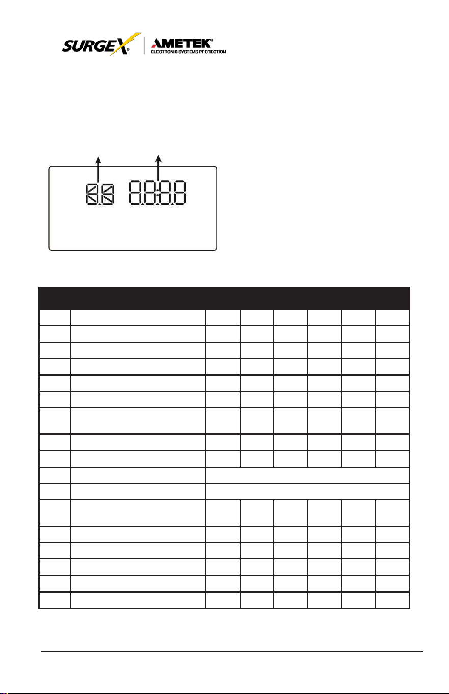
6.0 LCD SETTING
There are three parameters to set up the UPS. Refer to following
diagram.
Parameter 1 Parameter 2
Parameter 1: Program alternatives.
Refer to below
table.
Parameter 2: iSetting values for each
program.
15 Programs Available List for Parameter 1:
Code Description Bypass AC ECO CVCF Battery
01 Output
voltage
Y
02 Output
frequency
Y
03 Voltage range for bypass
Y
04
Frequency range
for
bypass
Y
05 ECO
mode enable/disable
Y
06 Voltage
range
for ECO
mode
Y
07 ECO
mode frequency
range
setting
Y
08 Bypass mode setting
Y Y
Battery
Test
09 Battery backup time setting
Y Y Y Y Y Y
10
Reserved
Reserved
for
future
11
Reserved
Reserved
for
future
12 Hot standby function enable/
disable
Y Y Y Y Y Y
13 Battery voltage adjustment
Y Y Y Y Y Y
14 Charger voltage adjustment
Y Y Y Y Y Y
15 Inverter voltage adjustment
Y Y Y
16 Output
voltage calibration
Y Y Y
17 Charging current setting
Y Y Y Y Y Y
*Y means that this program can be set in this
mode.
26
User Manual
_________________________________________________________
© 2020 AMETEK Electronic Systems Protection / Technical Support: 1-800-645-9721 / ametekesp.com
NOTE:
Parameter settings will be saved only when
UPS
shuts down
normally with internal or external battery connection. (Normal
UPS
shutdown means turning off input breaker in bypass/no
output mode).
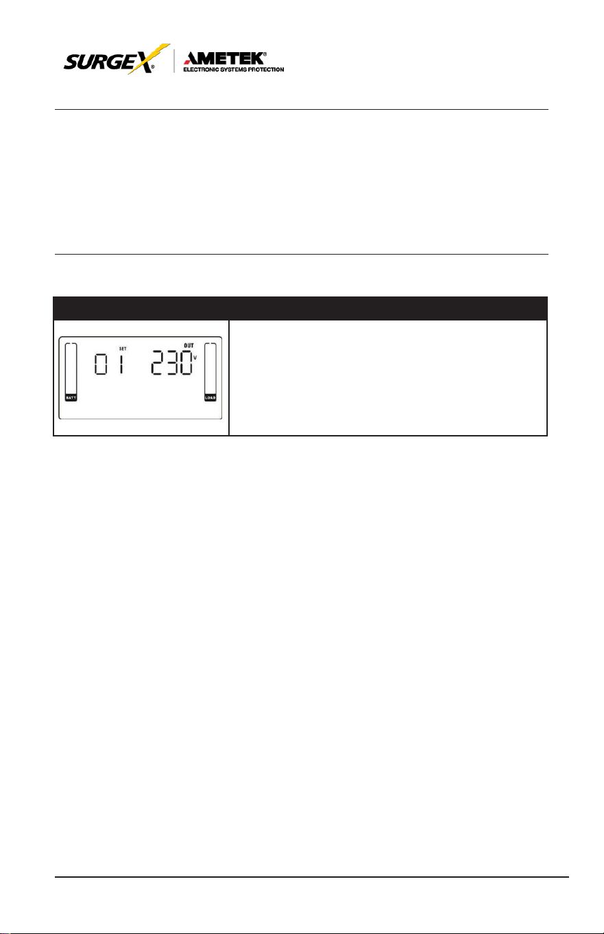
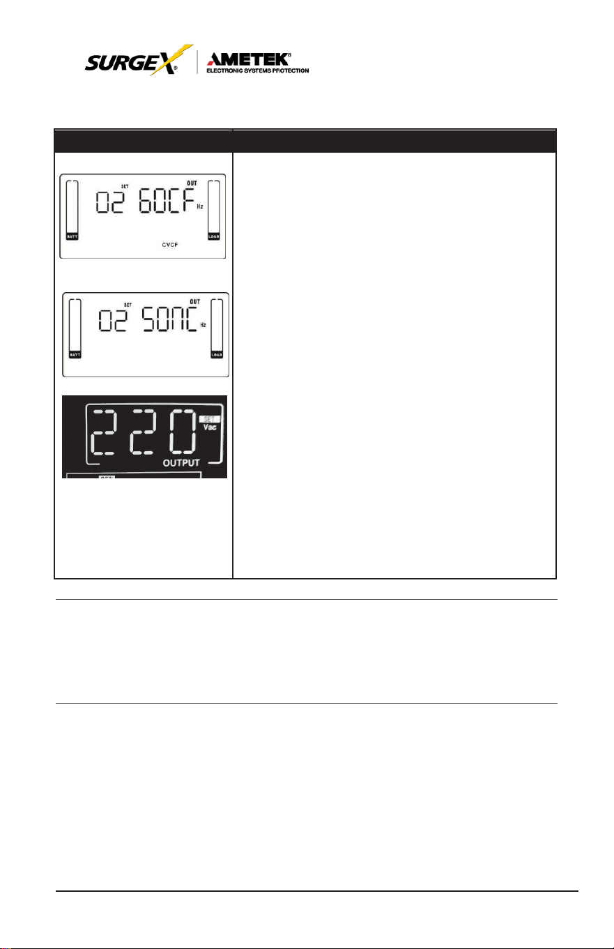
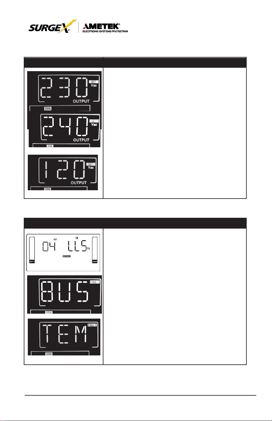
01: Output Voltage
Interface
Setting
Parameter 3: Output voltage
You may choose the following output voltage in
parameter 3:
208: Output
voltage
is 208VAC
220: Output
voltage
is 220VAC
230: Output
voltage
is 230VAC
240: Output
voltage
is 240VAC
27
User Manual
_________________________________________________________
© 2020 AMETEK Electronic Systems Protection / Technical Support: 1-800-645-9721 / ametekesp.com
02: Output Frequency
Interface
Setting
60 Hz, CVCF
mode
50 Hz, Normal
mode
AT
O
Parameter 2: Output Factory
Setting the output frequency. You may choose following three
options in parameter 2:
50CF: Setting UPS to CVCF
mode
and output
frequency
will
be fixed at 50Hz. The input
frequency
can
range
from 46Hz
to 64Hz.
60CF: Setting UPS to CVCF
mode
and output
frequency
will
be fixed at 60Hz. The input
frequency
can
range
from 46Hz
to 64Hz.
50NC: Setting UPS to normal
mode
(not CVCF
mode).
If
selected, the output frequency will synchronize with the input
frequency within 46~54 Hz.
UPS
will transfer to battery mode
when input frequency is not within 46~54
Hz.
60NC: Setting UPS to normal
mode
(not CVCF
mode).
If
selected, the output frequency will synchronize with the input
frequency within 56~64 Hz.
UPS
will transfer to battery mode
when input frequency is not within 56~64
Hz.
At: If selected, output frequency will be decided
according to the latest normal utility frequency. If it is from
46Hz to 54Hz, the output frequency will be
50.0Hz. If it is from 56Hz to 64Hz, the output frequency will be
60.0Hz. The last two digits will show the current
frequency.
At
is default
setting.
NOTE:
If
the UPS is set to CVCF
mode,
the
bypass
function
will
be
disabled automatically.
28
User Manual
_________________________________________________________
© 2020 AMETEK Electronic Systems Protection / Technical Support: 1-800-645-9721 / ametekesp.com
03: Voltage Range for Bypass
Interface
Setting
Parameter 1 & 2: Setting acceptable voltage range
for bypass mode. Set up the range by setting high and low
points. When it
shows
“LLS”
in
parameter
2,
please
press
“Enter” key and it
will
show “LS” in
parameter
1. Now the low point in parameter 2 can be set up by
pressing
“Up” or “Down”
key.
LS: Set the acceptable low voltage for bypass. Setting
range
is from 110V to 209V and the default value
is
110V.
Pressing
“Enter” key to confirm the
setting
value for
low point. Then, it will show HS in parameter 1. Please set
up high point in
parameter
2 by
pressing
“Up” or
“Down”
key.
HS: Set the acceptable high voltage for bypass. Setting
range
is from 231V to 276V and the default value
is
264V.
04: Frequency Range for Bypass
Interface
Setting
Parameter 1 & 2: Setting acceptable frequency range for
bypass mode. Set up the range by setting high and low points.
When it
shows
“LLS”
in
parameter
2,
please press
“Enter”
key and it
will
show “LS” in
parameter
1. Now the low point in parameter 2 can be set up by
pressing
“Up” or “Down”
key.
LS: Set the acceptable low frequency for bypass.
50 Hz
system:
Setting
range
is from 46.0Hz to
49.0Hz.
60 Hz
system:
Setting
range
is from 56.0Hz to
59.0Hz.
The default value is 46.0Hz/56.0Hz.
Pressing
“Enter” key to confirm the
setting
value for low
point. Then, it will show HS in parameter 1. Set up high point in
parameter
2 by
pressing
“Up” or “Down”
key.
HS: Set the acceptable high frequency for bypass. 50
Hz: Setting range is from 51.0Hz to 54.0 Hz.
60 Hz: Setting range is from 61.0Hz to 64.0Hz. The default
value is 54.0Hz/64.0Hz.
29
User Manual
_________________________________________________________
© 2020 AMETEK Electronic Systems Protection / Technical Support: 1-800-645-9721 / ametekesp.com
05: ECO Mode Enable/Disable
Interface
Setting
Parameter 2:
Enable
or
disable
ECO function. You
may
choose following two options:
DIS:
disable
ECO function
ENA:
enable
ECO function
If
ECO function is
disabled, voltage range
and fre-
quency range
for ECO
mode
still can be set, but it
is
meaningless unless
the ECO function is
enabled.
06: Voltage Range for ECO Mode
Interface
Setting
Parameter 1 & 2: Setting acceptable voltage range for
ECO
mode.
Set up the
range
by
setting
high and low
points. When it
shows
“LLS”
in
parameter
2,
please
press
“Enter” key and it
will
show “LS” in
parameter
1. Now the low point in parameter 2 can be set up by
pressing
“Up” or “Down”
key.
LS: Low
voltage
point in ECO
mode.
The
setting
range
is from 5% to 10% of the nominal voltage.
Pressing
“Enter” key to confirm the
setting
value for low
point. Then, it will show HS in parameter 1. Set up high
point in
parameter
2 by
pressing
“Up” or “Down”
key.
HS: High
voltage
point in ECO
mode.
The
setting
range
is from 5% to 10% of the nominal voltage.
30
User Manual
_________________________________________________________
© 2020 AMETEK Electronic Systems Protection / Technical Support: 1-800-645-9721 / ametekesp.com
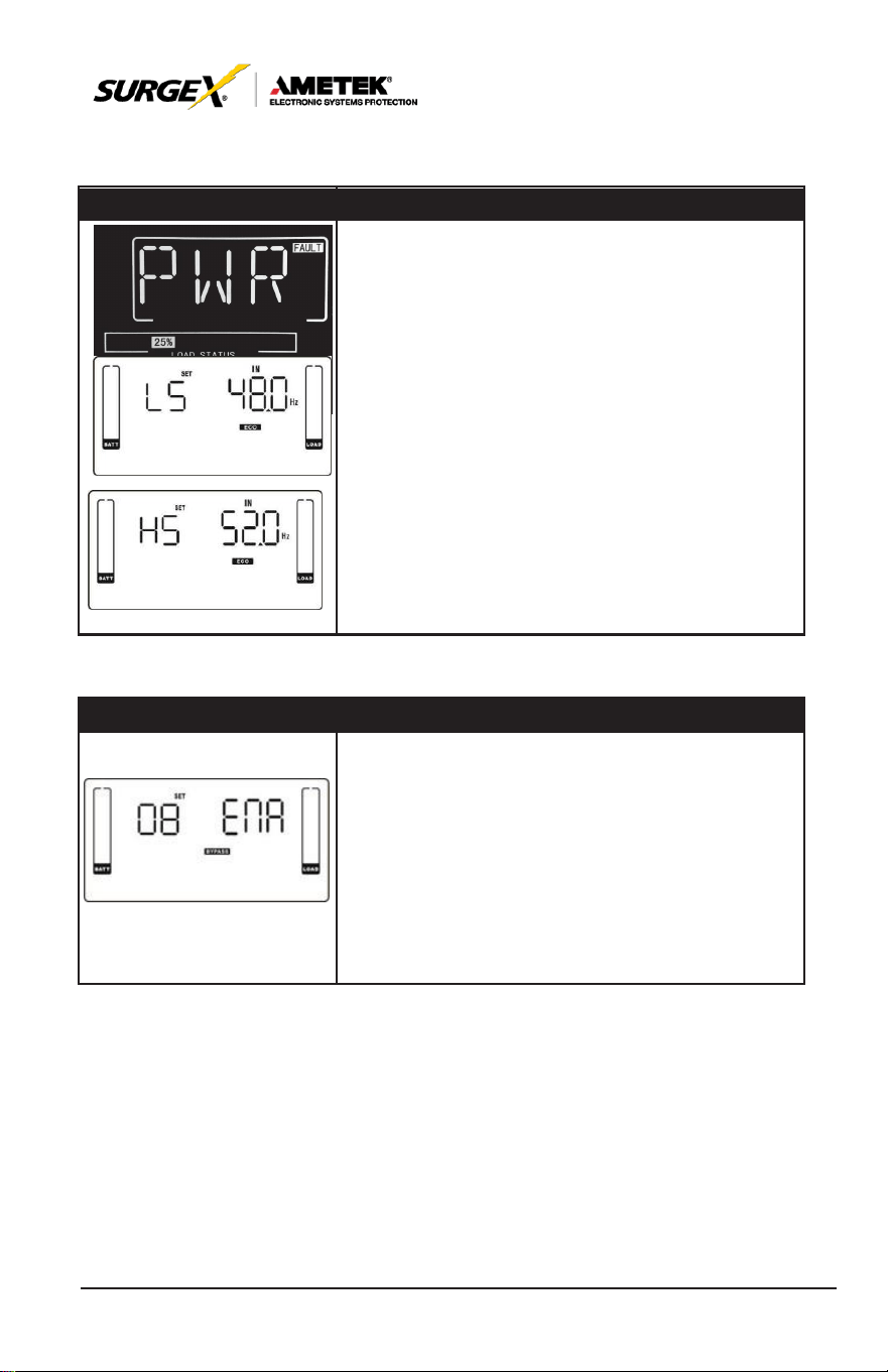
07: Frequency Range for ECO Mode
Interface
Setting
Parameter 1 & 2: Setting acceptable frequency range
for ECO
mode.
Set up the
range
by
setting
high
and
low points. When it
shows
“LLS”
in
parameter
2,
please
press
“Enter” key and it
will
show “LS” in
parameter
1. Now the low point in parameter 2 can be set up by
pressing
“Up” or “Down”
key.
LS: Set low
frequency
point for ECO
mode.
50 Hz system: Setting range is from 46.0Hz to 48.0Hz.
60 Hz system: Setting range is from 56.0Hz to 58.0Hz. The
default value is 48.0Hz/58.0Hz.
Pressing
“Enter” key to confirm the
setting
value for low
point. Then, it will show HS in parameter 1. Set up high point in
parameter
2 by
pressing
“Up” or “Down”
key.
HS: Set high
frequency
point for ECO
mode.
50 Hz:
Setting range is from 52.0Hz to 54.0 Hz.
60 Hz: Setting range is from 62.0Hz to 64.0Hz. The default
value is 52.0Hz/62.0Hz.
08: Bypass Mode Setting
Interface
Setting
After it
shows
“08” in
parameter
1,
please press “Enter”
key first. Then, you have the following
options
to
choose
in
ENA/DIS.
ENA: Bypass enabled. When selected, Bypass mode is
activated.
DIS: Bypass disabled. When selected, automatic bypass is
acceptable, but manual bypass is not allowed. Manual bypass
means users manually operate UPS for
Bypass mode.
For
example, pressing OFF
button in AC
mode
to turn into
Bypass mode.
31
User Manual
_________________________________________________________
© 2020 AMETEK Electronic Systems Protection / Technical Support: 1-800-645-9721 / ametekesp.com
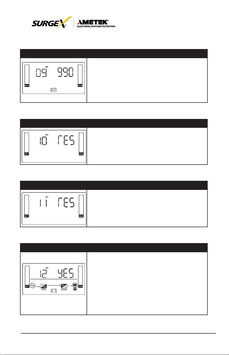
09: Battery Backup Time Setting
Interface
Setting
Parameter 2:
000~999: Set the maximum backup time from 0min
to 999min. UPS
will
shut down to
protect battery after
backup
time arrives. The default value is 990min.
DIS: Disable battery discharge protection and backup time will
depend on battery capacity.
The default value is DIS.
10: Reserved
Interface
Setting
Reserved
11: Reserved
Interface
Setting
Reserved
12: Hot Standby Function Enable/disable
Interface
Setting
Parameter 2: HS.H
Enable or disable Hot standby function. You may
choose following two options in Parameter 2:
YES: Hot standby function is enabled. It means that the
current
UPS
is set to host of the hot standby function,
and it
will
restart
after AC
recovery
even without
battery
connected.
NO: Hot standby function is disabled. The
UPS
is
running at normal mode and can’t restart without
battery.
32
User Manual
_________________________________________________________
© 2020 AMETEK Electronic Systems Protection / Technical Support: 1-800-645-9721 / ametekesp.com
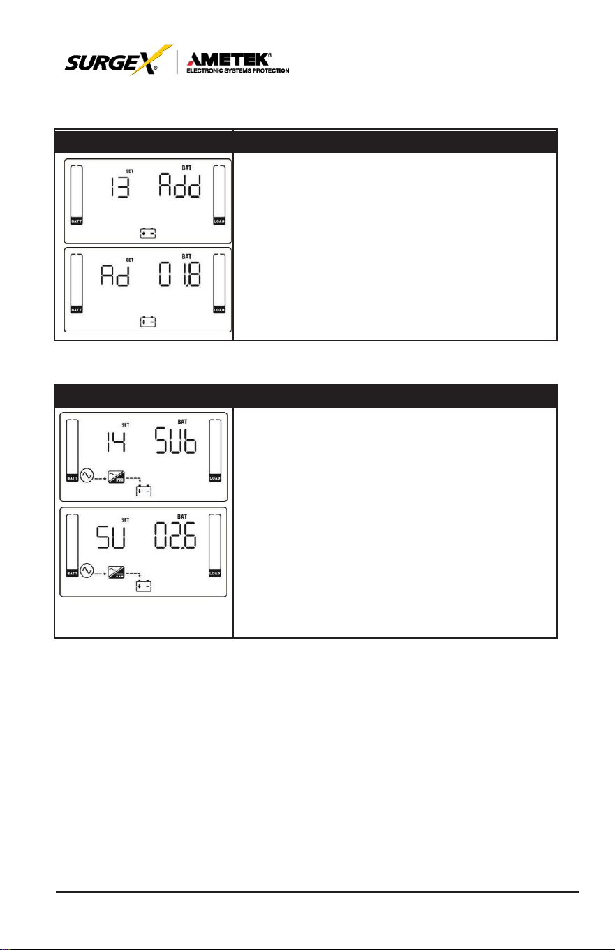
13: Battery Voltage Adjustment
Interface
Setting
After it
shows
“13” in
parameter
1,
please press
“Enter”
key first. Then, you may
choose
Add or SUB
to adjust battery voltage in Parameter 1 by
pressing
“Up” or “Down” key. After
pressing
“Enter” key to
confirm your selection, it will jump to parameter 2 to set
up the value.
Parameter 2: the voltage range is from 0V to 5.7V, the
default value is 0V.
14: Charger Voltage Adjustment
Interface
Setting
After it
shows
“14” in
parameter
1,
please press “Enter”
key first. Then, you may
choose
Ad or SU to adjust charger
voltage in Parameter 1 by
pressing
“Up” or “Down” key. After
pressing
“Enter” key to confirm your selection, it will jump to
parameter 2 to set up the value.
Parameter 2: the
voltage range
is from 0V to 9.9V,
the
default value is 0V.
NOTE:
*Before making voltage adjustment, be sure to
disconnect
all
batteries
first to get the
accurate charger
voltage.
*We strongly suggest using the default value (0). Any
modification should
be
suitable
to
battery
specifications.
33
User Manual
_________________________________________________________
© 2020 AMETEK Electronic Systems Protection / Technical Support: 1-800-645-9721 / ametekesp.com
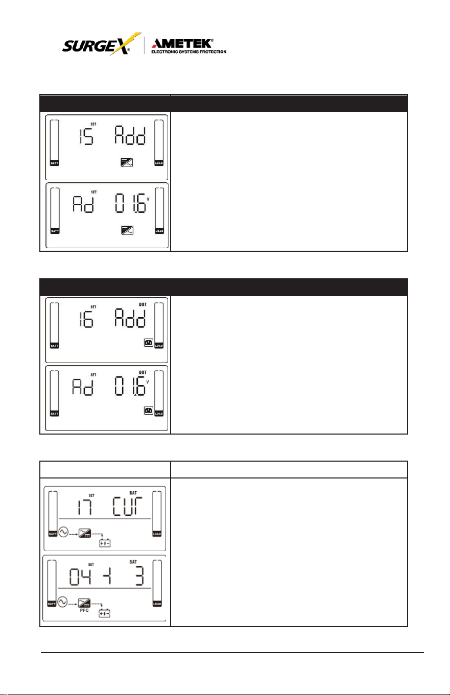
15: Inverter Voltage Adjustment
Interface
Setting
After it
shows
“15” in
parameter
1,
please press
“Enter”
key first. Then, you may
choose
Ad or SU to
adjust inverter voltage in Parameter 1 by
pressing
“Up” or “Down” key. After
pressing
“Enter” key to
confirm your selection, it will jump to parameter 2 to set
up the value.
Parameter 2: the voltage range is from 0V to 6.4V, the
default value is 0V.
16: Output Voltage Calibration
Interface
Setting
After it
shows
“16” in
parameter
1,
please press “Enter”
key first. Then, you may
choose
Ad or SU to adjust output
voltage in Parameter 1 by
pressing
“Up” or “Down” key.
After
pressing
“Enter” key to confirm your selection, it will
jump to parameter 2 to set up the value.
Parameter 2: the voltage range is from 0V to 6.4V, the
default value is 0V.
17: Charging Current Setting
Interface
Setting
After it
shows
“17” in
parameter
1 and “Cur” in
parameter
2,
please press
“Enter” key first. Then, you may
select
01, 02, 03
or 04 to set the
charging current
from 1A to 4A in Parameter 1.
Then,
calibrate
the
charging current
by
selecting
“+” or
“-“ in Parameter 2.
± 0~± 5: You may choose ‘+’ as Add or ‘-’ as Sub to
adjust
charging current.
This
setting number
is the first number after the
decimal point.
For
example,
if
setting
value is “+” and “3”, it
means the
calibrated
formula is to
add
0.3A. The
setting charging current
will
become
4.3A
as
shown in left
screen.
(4A
+
0.3A = 4.3A.)
34
User Manual
_________________________________________________________
© 2020 AMETEK Electronic Systems Protection / Technical Support: 1-800-645-9721 / ametekesp.com
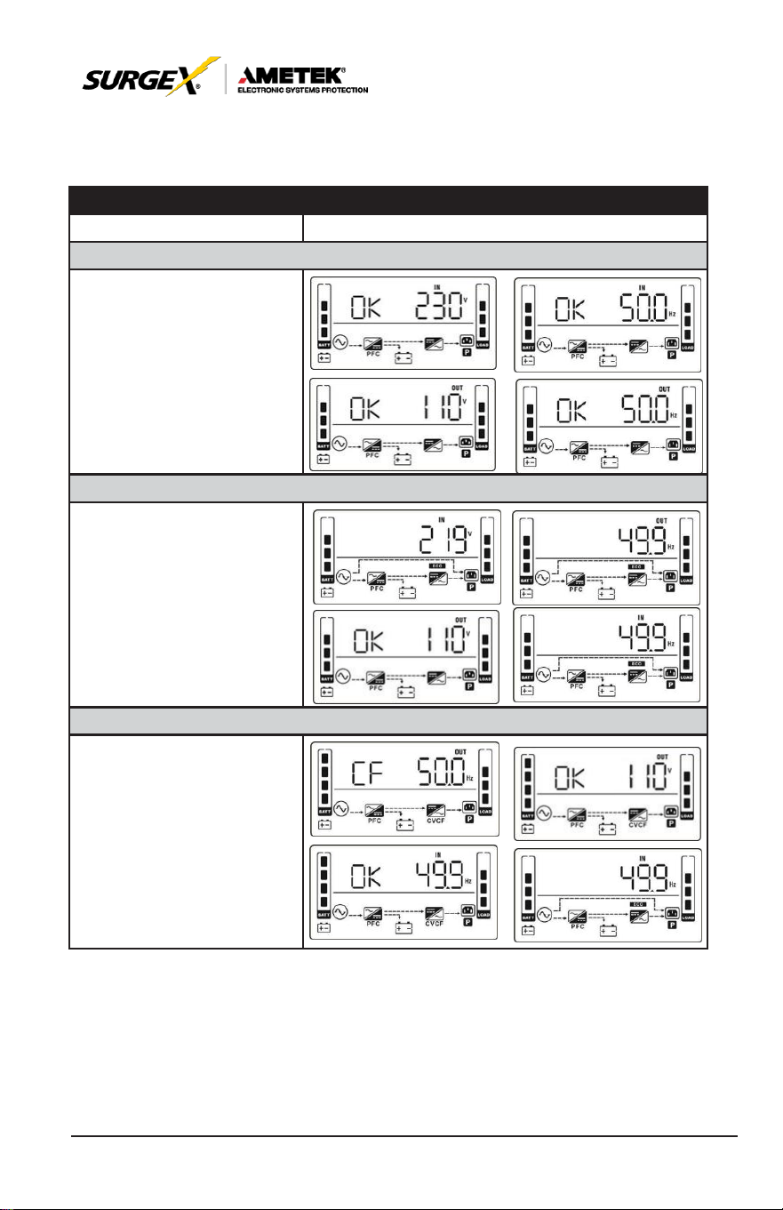
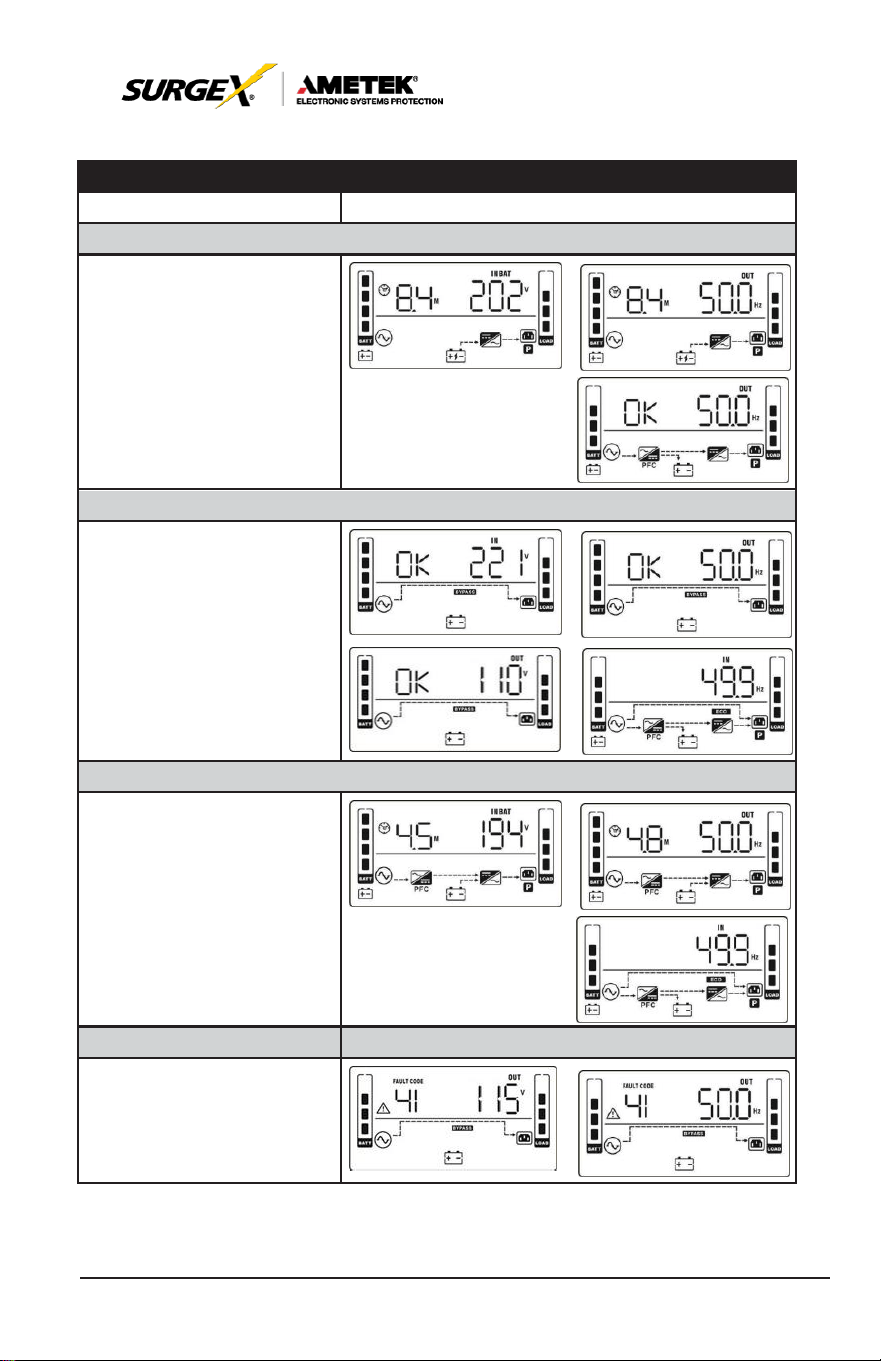
7.0 OPERATION MODE/STATUS DESCRIPTION
OPERATING MODE/STATUS
Description
LCD Display
AC Mode
When the input voltage is
within acceptable range, UPS
will provide pure and stable
AC power to output. The
UPS will also charge the
battery at AC
mode.
ECO Mode
When the input voltage is
within voltage regulation range
and ECO
mode
is
enabled,
UPS
will bypass voltage to
output for energy saving.
CVCF Mode
When input frequency is within
46 to 64Hz, the
UPS
can
be set at a constant output
frequency, 50 Hz or 60 Hz.
The
UPS
will still charge
battery under this mode.
35
User Manual
_________________________________________________________
© 2020 AMETEK Electronic Systems Protection / Technical Support: 1-800-645-9721 / ametekesp.com
OPERATING MODE/STATUS
Description
LCD Display
Battery Mode
When the input voltage is
beyond the acceptable range
or power failure,
UPS
will
backup power from battery
and alarm will beep every 4
seconds.
Bypass Mass
When input voltage is within
acceptable range and bypass
is enabled, turn off the UPS
and it will enter Bypass mode.
Alarm beeps every two min-
utes.
Battery Test
When UPS is in AC mode
or CVCF mode, press “Test”
key for more than 0.5s. Then
the UPS will beep once and
start “Battery Test”. The line
between I/P and inverter icons
will blink to remind users. This
operation
is used to check the battery
status.
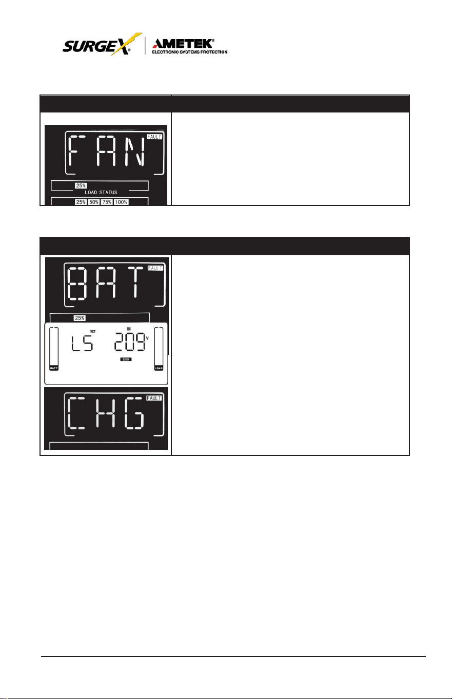
Fault Status
When UPS has fault
happened, it will display fault
messages in LCD panel.
36
User Manual
_________________________________________________________
© 2020 AMETEK Electronic Systems Protection / Technical Support: 1-800-645-9721 / ametekesp.com
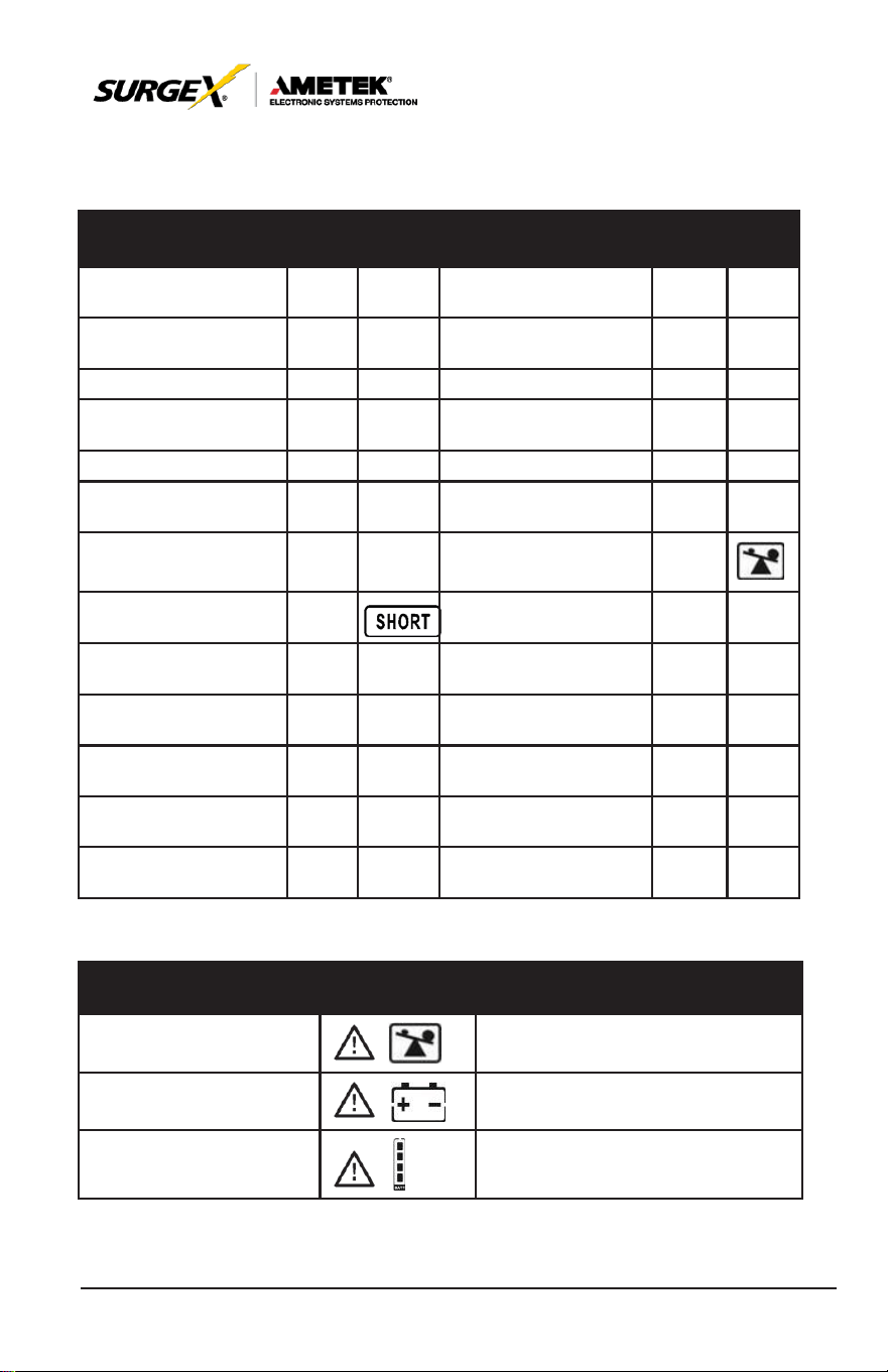
8.0 FAULT CODE
Fault Event
Fault
Code
Icon
Fault Event
Fault
Code
Icon
Bus start failure
01
None
Battery SCR
short
circuited
21
None
Bus over
02
None
Inverter relay short
circuited
24
None
Bus under
03
None
Charger short circuited
2a
None
Bus unbalance
04
None
Can communication
fault
31
None
Inverter soft start failure
11
None
Over
temperature
41
None
High Inverter voltage
12
None
CPU communication
failure
42
None
Low Inverter voltage
13
None
Overload
43
Inverter output short
circuited
14
Battery turn-on failure
6A
None
Negative power fault
1A
None
PFC
current
failure in
battery mode
6B
None
Inverter over current
60
None
Bus voltage changes
too fast
6C
None
Inverter waveform
abnormal
63
SPS
12V abnormal
6E
None
Inverter current detec-
tion error
6D
None
Transformer over tem-
perature
77
None
8.1 Warning Indicator
Warning
Icon
(Flashing)
Alarm
Overload
Beeping twice every second
Battery Unconnected
Beeping every second
Over
charge
Beeping every second
37
User Manual
_________________________________________________________
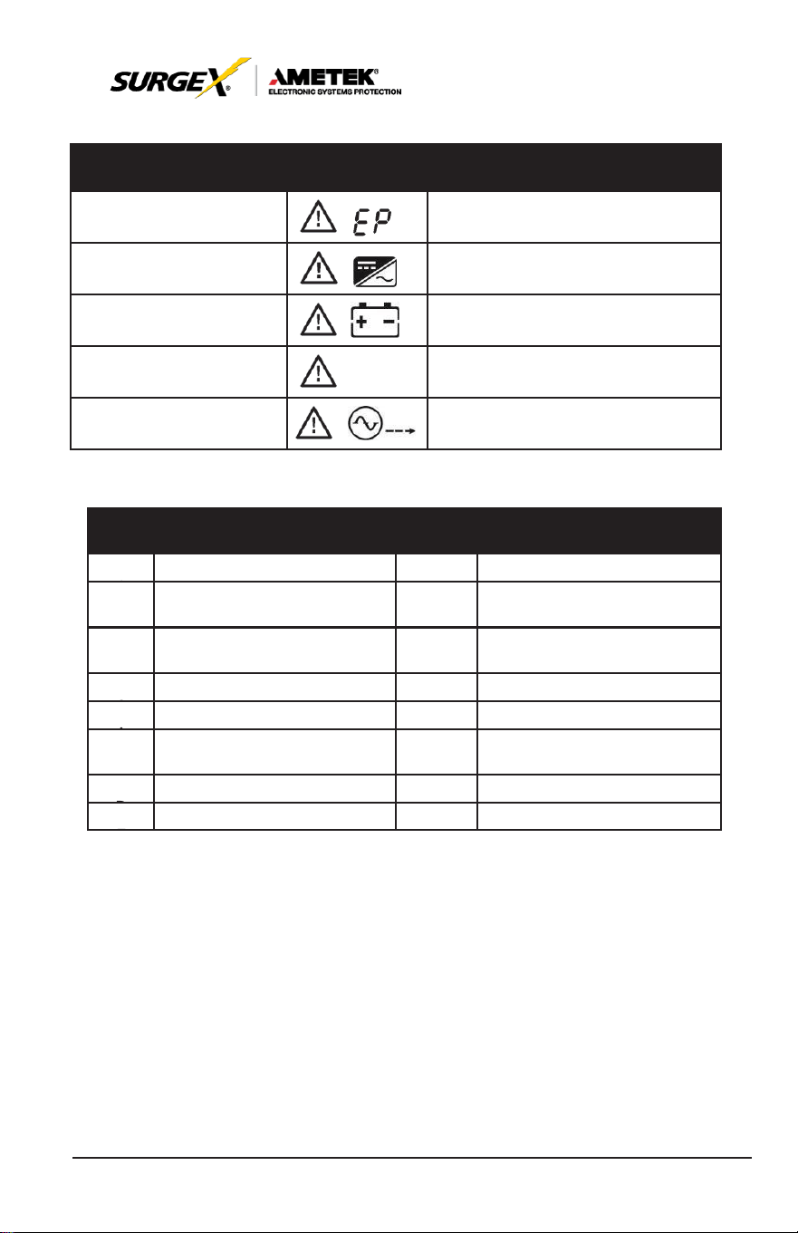
© 2020 AMETEK Electronic Systems Protection / Technical Support: 1-800-645-9721 / ametekesp.com
Warning
Icon
(Flashing)
Alarm
EPO
enable
Beeping every second
Fan failure/Over
tempera
- ture
Beeping every second
Charger failure
Beeping every second
I/P fuse broken
Beeping every second
Overload
3 times in 30min
Beeping every second
8.2 Warning Code
Warnin
g
Cod
e
Warning Event
Warning
Code
Warning Event
0
1
Battery unconnected
10
L1 IP fuse broken
0
7
Over
charge
33
Locked in bypass after
overload
3 times in 30min
0
8
Low battery
3A
Cover of maintain switch is
open
0
9
Overload
3D
Bypass unstable
0
A
Fan failure
3E
Boot loader is missing
0
B
EPO
enable
42
Over-temperature on
transformer
0
D
Over
temperature
0
E
Charger failure
38
User Manual
_________________________________________________________
© 2020 AMETEK Electronic Systems Protection / Technical Support: 1-800-645-9721 / ametekesp.com
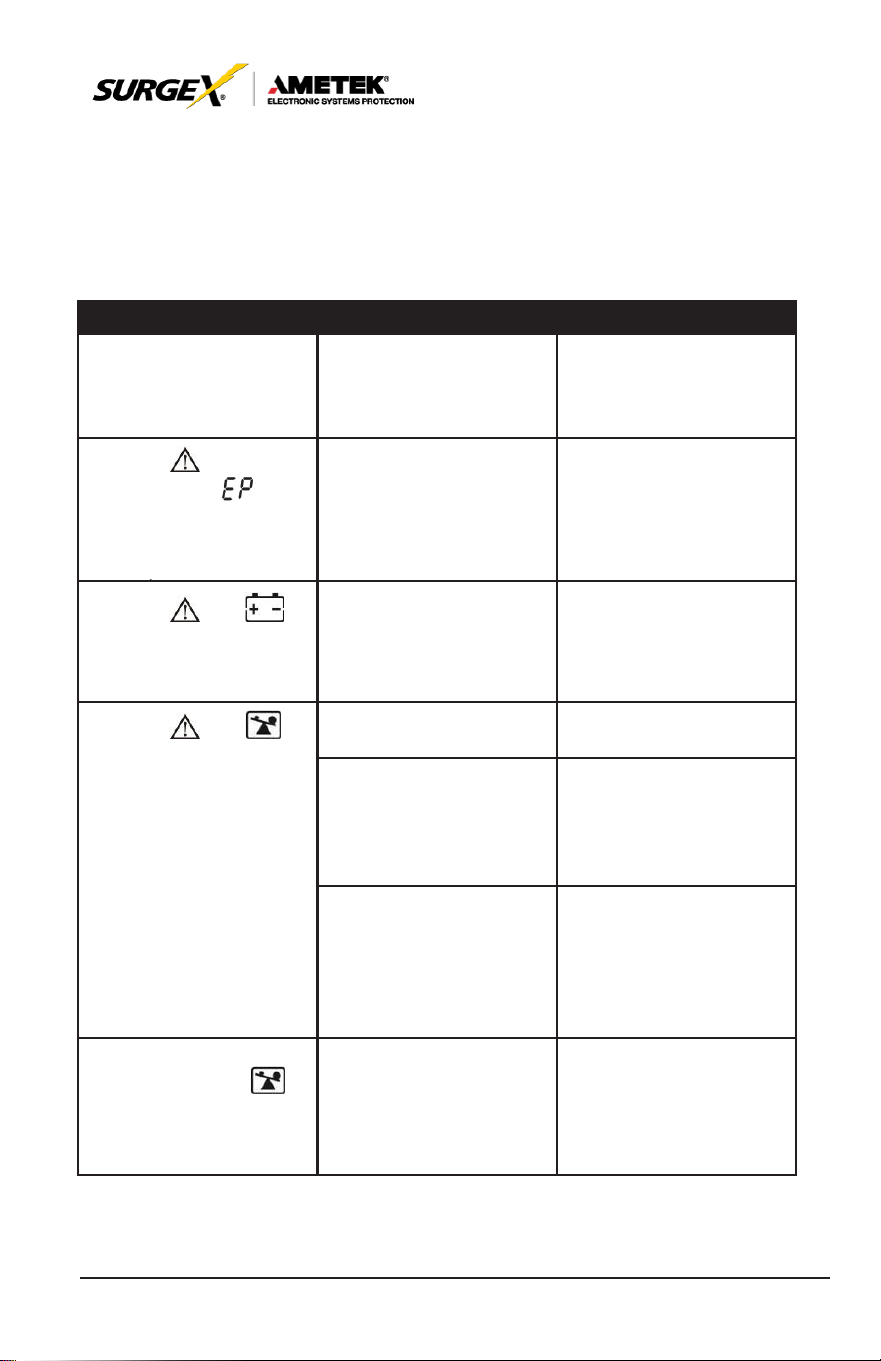
9.0 TROUBLESHOOTING
If the UPS system does not operate correctly, please solve the problem
by using the table below.
Symptom
Possible Cause
Remedy
No indication and alarm
in the front display panel
even though the mains
is normal.
The AC input power
is
not connected well.
Check if input cable
firmly
connected
to
the
mains.
The icon and the
warning code
flash
on LCD
display
and alarm beeps every
second.
EPO function is
enabled.
Set the circuit to closed
position to
disable
EPO
function.
The icon and
flash
on
LCD
display
and alarm beeps every
second.
The external or internal
battery is incorrectly
connected.
Check if all batteries are
connected well.
The icon and
flash
on
LCD
display
and alarm beeps twice
every second.
UPS
is on overload.
Remove
excess loads
from
UPS
output.
UPS
is overloaded.
Devices connected to
the
UPS
are fed directly
by the electrical network
via the Bypass.
Remove
excess loads
from
UPS
output.
After
repetitive
overloads, the
UPS
is
locked in the Bypass
mode. Connected
devices are fed directly
by the mains.
Remove
excess loads
from UPS output first.
Then shut down the UPS
and restart it.
Fault
code
is
shown
as
43. The icon
lights on LCD display
and alarm beeps
continuously.
UPS
is overload too
long and becomes fault.
Then
UPS
shut down
automatically.
Remove
excess
loads
from
UPS
output and restart it.
39
User Manual
_________________________________________________________
© 2020 AMETEK Electronic Systems Protection / Technical Support: 1-800-645-9721 / ametekesp.com
Symptom
Possible Cause
Remedy
Fault
code
is
shown
as 14 on LCD display,
and alarm beeps
continuously.
The
UPS
shut down
automatically because
short circuit occurs on
the
UPS
output.
Check output wiring and
if connected devices are
in short circuit status.
Fault
code
is
shown
as
01, 02,
03,
04,11,
12, 13, 14,1A, 21,
24,
35, 36, 41, 42 or
43
on
LCD display
and alarm beeps
continuously.
A UPS internal fault
has
occurred. There are two
possible results:
1. The load is still sup-
plied, but directly from
AC power via
bypass.
2. The load is no longer
supplied by power.
Contact Technical
Support.
Battery backup time is
shorter than nominal
value
Batteries are not fully
charged
Charge the batteries for
at least 7 hours and then
check capacity. If the
problem still persists,
Technical Support.
The icon and
flash
on
LCD
display
and alarm beeps every
second.
Fan is
locked
or
not
working; or the UPS
temperature is too high.
Check fans and notify
dealer.
40
User Manual
_________________________________________________________
© 2020 AMETEK Electronic Systems Protection / Technical Support: 1-800-645-9721 / ametekesp.com
10.0 STORAGE AND MAINTENANCE
10.1. Storage
Before storing, charge the UPS at least 7 hours. Store the UPS covered
and upright in a cool, dry location. During storage, recharge the battery in
accordance with the following table:
Storage Temperature
Recharge Frequency
Charging Duration
-25°C -
40°C
Every 3
months
1-2 hours
40°C -
45°C
Every 2 months
1-2 hours
10.2 Maintenance
CAU
TION
The UPS
system operates
with
hazardous voltages. Repairs
may be
carried
out only by qualified
maintenance personnel.
CAU
TION
Even after the unit is disconnected from the mains, components
inside the
UPS
system are still connected to the battery packs which
are potentially dangerous.
CAU
TION
Before carrying out any kind of service and/or maintenance,
disconnect the batteries and verify that no current is present and no
hazardous voltage exists in the terminals of high capability capacitor
such as BUS-capacitors.
CAU
TION
Only
persons
are
adequately
familiar with
batteries
and with
the
required precautionary measures may replace batteries and
supervise operations. Unauthorized persons must be kept well away
from the batteries.
41
User Manual
_________________________________________________________
© 2020 AMETEK Electronic Systems Protection / Technical Support: 1-800-645-9721 / ametekesp.com
CAU
TION
Verify that no voltage between the battery terminals and the ground
is present before maintenance or repair. In this product, the battery
circuit is not isolated from the input voltage. Hazardous voltages
may occur between the battery terminals and the ground.
CAU
TION
Batteries may cause electric shock and have a high short-circuit
current. Please remove all wristwatches, rings and other metal
personal objects before maintenance or repair, and only use tools
with insulated grips and handles for maintaining or repairing.
CAU
TION
When replace the batteries, install the same number and same type
of batteries.
CAU
TION
Do not attempt to dispose of batteries by burning them. This could
cause battery explosion. The batteries must be rightly deposed
according to local regulation.
CAU
TION
Do not open or destroy batteries. Escaping electrolyte can cause
injury to the skin and eyes. It may be toxic.
CAU
TION
Please replace the fuse only with the same type and amperage in
order to avoid fire
hazards.
CAU
TION
Do not disassemble the
UPS
system.