Contact Information
If you need to contact ASRock or want to know more about ASRock, you’re welcome
to visit ASRock’s website at http://www.asrock.com; or you may contact your dealer
for further information. For technical questions, please submit a support request
form at https://event.asrock.com/tsd.asp
ASRock Incorporation
e-mail: [email protected]
ASRock EUROPE B.V.
e-mail: sales@asrock.nl
ASRock America, Inc.
e-mail: sales@asrockamerica.com
Scan the QR code to view more manuals and documents.

Contents
Chapter 1 Introduction 1
1.1 Package Contents 1
1.2 Specications 2
1.3 Motherboard Layout 7
1.4 I/O Panel 9
1.5 Block Diagram 11
1.6 802.11be Wi-Fi 7 Module and ASRock WiFi 2.4/5/6 GHz
Antenna 12
Chapter 2 Installation 13
2.1 Installing the CPU 14
2.2 Installing the CPU Fan and Heatsink 17
2.3 Installing Memory Modules (DIMM)
26
2.4 Connecting the Front Panel Header 28
2.5 Installing the Motherboard 29
2.6 Installing SATA Drives 30
2.7 Installing a Graphics Card 32
2.8 Connecting Peripheral Devices 35
2.9 Connecting the Power Connectors 36
2.10 Power On 37
2.11 Jumpers Setup 38
2.12 Onboard Headers and Connectors 39

1
X870 Taichi Creator
Chapter 1 Introduction
ank you for purchasing ASRock X870 Taichi Creator motherboard, a reliable
motherboard produced under ASRock’s consistently stringent quality control.
It delivers excellent performance with robust design conforming to ASRock’s
commitment to quality and endurance.
1.1 Package Contents
•
ASRock X870 Taichi Creator Motherboard (ATX Form Factor)
•
4 x Serial ATA (SATA) Data Cables (Optional)
•
1 x ASRock WiFi 2.4/5/6 GHz Antenna (Optional)
•
1 x ARGB Splitter Cable (Optional)
•
1 x ermistor Cable (Optional)
Because the motherboard specications and the BIOS soware might be updated, the
content of this documentation will be subject to change without notice. In case any modi-
cations of this documentation occur, the updated version will be available on ASRock’s
website without further notice. If you require technical support related to this mother-
board, please visit our website for specic information about the model you are using. You
may nd the latest VGA cards and CPU support list on ASRock’s website as well. ASRock
website http://www.asrock.com.

2
1.2 Specications
Platform
•
ATX Form Factor
•
8 Layer PCB
CPU
•
Supports AMD Socket AM5 Ryzen
TM
9000, 8000 and 7000
Series Processors*
* e availability of expansion slots may vary by CPU. Please
refer to PCIe/M.2 Bandwidth Table for details. (http://www.
asrock.com/)
Chipset
•
AMD X870
Memory
•
Dual Channel DDR5 Memory Technology
•
4 x DDR5 DIMM Slots
•
Supports DDR5 ECC/non-ECC, un-buered memory up to
8000+(OC)*
•
Max. capacity of system memory: 256GB
•
Supports Extreme Memory Prole (XMP) and EXTended
Proles for Overclocking (EXPO) memory modules
* Please refer to Memory Support List on ASRock's website for
more information. (http://www.asrock.com/)
Expansion
Slot
CPU:
•
2 x PCIe 5.0 x16 Slots (PCIE1 and PCIE2), support x16 or x8/
x8 modes*
Chipset:
•
1 x PCIe 3.0 x16 Slot (PCIE3), supports x4 mode*
•
1 x Vertical M.2 Socket (Key E), supports type 2230 WiFi/BT
PCIe WiFi module
* PCIE1 will run at Gen5x16 with 9000 and 7000 series
processors, Gen4x8 with 8000 (Phoenix 1) series processors and
Gen4x4 with 8000 (Phoenix 2) series processors.
* If M2_4 is occupied, both PCIE3 and M2_4 will downgrade to
x2 mode.
* Supports NVMe SSD as boot disks

3
X870 Taichi Creator
Graphics
•
Integrated AMD RDNA
TM
graphics (Actual support may
vary by CPU)
•
1 x HDMI 2.1 TMDS/FRL 8G Compatible, supports HDR,
HDCP 2.3 and max. resolution up to 4K 120Hz
•
2 x USB4, support HDCP 2.3 and max. resolution up to 8K
30Hz*
* Only the CPU's embedded graphics can be displayed through
USB4 ports. If you want to display to a Type-C monitor,
please use AM5 Ryzen
TM
9000, 8000 and 7000 processors with
embedded graphics.
* USB4 controller (for USB4_TC1 and USB4_TC2) will run at
Gen4x2 with with 8000 (Phoenix 2) series processors.
Audio
•
7.1 CH HD Audio with Content Protection (Realtek
ALC4082 Audio Codec)
•
Individual PCB Layers for R/L Audio Channel
•
Nahimic Audio
LAN
1 x 10 Gigabit LAN 100/1000/2500/5000/10000 Mb/s (Marvell
(Aquantia) AQC113)
•
Support Wake-On-LAN
•
Support PXE
1 x 5 Gigabit LAN 10/100/1000/2500/5000 Mb/s (Realtek
RTL8126)
Wireless
LAN
•
802.11be 2x2 Wi-Fi 7 Module
•
Supports IEEE 802.11a/b/g/n/ac/ax/be
•
Supports 2.4GHz/5GHz/6GHz* frequency band
•
Supports 160MHz channel bandwidth with 6GHz* frequen-
cy band
* e Wi-Fi 7 module is supported by Microso® Windows® 11
only. ere is no driver available for Windows® 10. e avail-
ability of the 6GHz band will depend on the dierent regula-
tion status of each country and region. It will be activated (for
supported countries) through Windows® Update and soware
updates once available.
•
1 antenna to support 2 (Transmit) x 2 (Receive) diversity
technology
•
Supports Bluetooth 5.4
•
Supports MU-MIMO

4
USB
CPU:
•
2 x USB4 Type-C (Rear)
•
1 x USB 3.2 Gen2 Type-A (Rear (USB32_8))
•
4 x USB 3.2 Gen1 Type-A (Rear (USB32_1234))
Chipset:
•
1 x USB 3.2 Gen2x2 Type-C (Front)
•
1 x USB 3.2 Gen2 Type-A (Rear (USB32_7))
•
6 x USB 3.2 Gen1 Type-A (2 Rear (USB32_56), 4 Front)
•
8 x USB 2.0 (2 Rear, 6 Front)
* All USB ports support ESD Protection
Rear Panel
I/O
•
2 x Antenna Ports
•
1 x HDMI Port
•
1 x Optical SPDIF Out Port
•
2 x USB4 Type-C Ports (40 Gb/s)*
•
2 x USB 3.2 Gen2 Type-A Ports (10 Gb/s)
•
6 x USB 3.2 Gen1 Type-A Ports (USB32_1234 supports Ultra
USB Power.)
•
2 x USB 2.0 Ports
•
2 x RJ-45 LAN Ports
•
1 x Clear CMOS Button
•
1 x BIOS Flashback Button
•
1 x Line Out Jack (Gold Audio Jack)
•
1 x Microphone Input Jack (Gold Audio Jack)
* Supports USB PD 3.0 up to 5V@3A (15W) charging
* USB4 controller
(for USB4_TC1 and USB4_TC2) will run at
Gen4x2 with with 8000 (Phoenix 2) series processors.
Storage
CPU:
•
1 x Blazing M.2 Socket (M2_1, Key M), supports type 2280
PCIe Gen5x4 (128 Gb/s) mode*
•
1 x Blazing M.2 Socket (M2_2, Key M), supports type 2280
PCIe Gen5x4 (128 Gb/s) mode*
Chipset:
•
1 x Hyper M.2 Socket (M2_3, Key M), supports type 2280
PCIe Gen4x4 (64 Gb/s) mode*
•
1 x Ultra M.2 Socket (M2_4, Key M), supports type 2280
PCIe Gen3x4 (32 Gb/s) mode*
ASMedia ASM1164:
•
4 x SATA3 6.0 Gb/s Connectors

5
X870 Taichi Creator
* Supports NVMe SSD as boot disks
* M2_1 is the rst priority for M.2 installation.
* M2_1 will run at Gen5x4 with 9000 and 7000 series processors
and Gen4x4 with 8000 (Phoenix 1 and Phoenix 2) series proces-
sors.
* M2_2 will run at Gen5x4 with 9000 and 7000 series proces-
sors and Gen4x4 with 8000 (Phoenix 1) series processors. M2_2
will be unavailable with 8000 (Phoenix 2) series processors.
* If M2_2 is occupied, both rear USB4 Type-C Ports and M2_2
will downgrade to x2 mode. You can switch M2_2 to x4 mode
in BIOS setting, but doing so will disable USB4_TC1 and USB4_
TC2.
* If M2_4 is occupied, both PCIE3 and M2_4 will downgrade to
x2 mode.
RAID
•
Supports RAID 0, RAID 1 and RAID 10 for M.2 NVMe stor-
age devices
Connector
•
1 x ermistor Cable Header
•
1 x Power LED and Speaker Header
•
1 x RGB LED Header*
•
3 x Addressable LED Headers**
•
2 x CPU Fan Connector (4-pin) (Smart Fan Speed Con-
trol)***
•
4 x Chassis Fan Connectors (4-pin) (Smart Fan Speed Con-
trol)***
•
1 x AIO Pump Fan Connector (4-pin) (Smart Fan Speed
Control)***
•
1 x 24 pin ATX Power Connector (Hi-Density Power Con-
nector)
•
2 x 8 pin 12V Power Connectors (Hi-Density Power Connec-
tor)
•
1 x Front Panel Audio Connector (15μ Gold Audio Connec-
tor)
•
3 x USB 2.0 Headers (Support 6 USB 2.0 ports)
•
2 x USB 3.2 Gen1 Headers (Support 4 USB 3.2 Gen1 ports)
•
1 x Front Panel Type C USB 3.2 Gen2x2 Header (20 Gb/s)****
•
1 x Dr. Debug with LED
•
1 x Power Button with LED
•
1 x Reset Button with LED
6
* Supports in total up to 12V/3A, 36W LED Strip
** Support in total up to 5V/3A, 15W LED Strip
*** CPU_FAN1 supports the fan power up to 1A (12W).
*** CPU_FAN2, CHA_FAN1~4 and AIO_PUMP support the
fan power up to 3A (36W).
*** CPU_FAN2, CHA_FAN1~4 and AIO_PUMP can auto
detect if 3-pin or 4-pin fan is in use.
**** Supports USB PD 3.0 up to 12V@3A (36W) charging
BIOS
Feature
•
AMI UEFI Legal BIOS with GUI support
OS
•
Microso® Windows® 10 64-bit / 11 64-bit
Certica-
tions
•
FCC, CE
•
ErP/EuP ready (ErP/EuP ready power supply is required)
•
CEC Tier II ready
Please realize that there is a certain risk involved with overclocking, including adjusting
the setting in the BIOS, applying Untied Overclocking Technology, or using third-party
overclocking tools. Overclocking may aect your system’s stability, or even cause damage to
the components and devices of your system. It should be done at your own risk and expense.
We are not responsible for possible damage caused by overclocking.
* For detailed product information, please visit our website:
http://www.asrock.com
7
X870 Taichi Creator
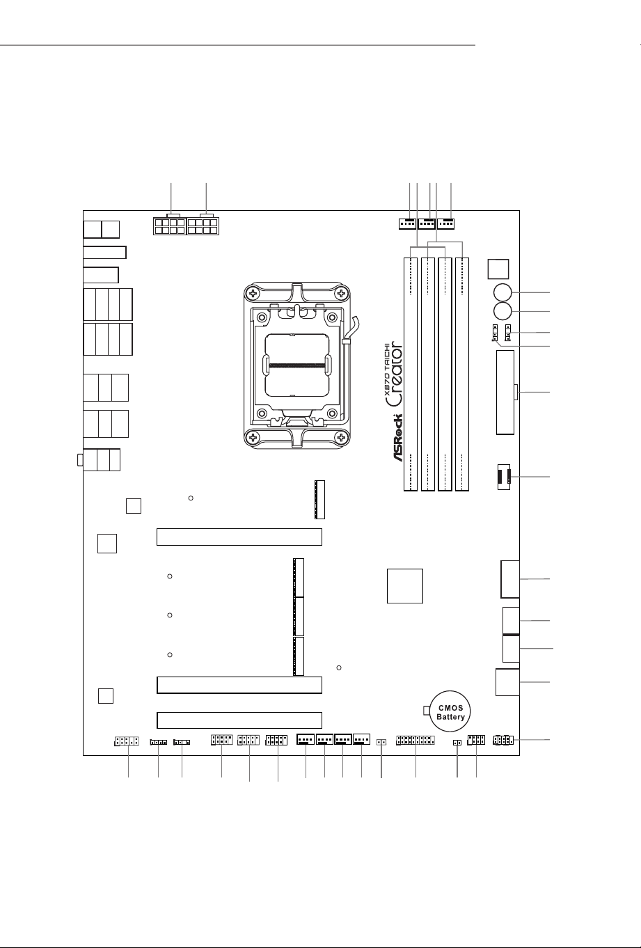
1.3 Motherboard Layout
ATXPWR1
PCIE1
SPK_PLED1
12
13
14
15
16
18
1
Dr.
Debug
Reset
Power
3
19
ATX 12V1
AMD
X870
USB32_TC1
2
HDLED RESET
PLED PWRBTN
PANEL1
1
AIO_PUMP
CPU_FAN1
7
4
DDR5_A2 (64 bit, 288-pin module)
DDR5_A1 (64 bit, 288-pin module)
DDR5_B2 (64 bit, 288-pin module)
DDR5_B1 (64 bit, 288-pin module)
1
20
ATX 12V2
6
SATA3 _A2
SATA3 _A1
RGB_LED1
1
ADDR_LED1
1
1
USB32_9_10
CLRCMOS1
1
M2_4
M2_3
30
31
32
1
ADD R_LED 2
1
ADD R_LED 3
8
9
M2_1
CPU_FAN2
5
11
USB_5_6
1
USB_3_4
1
CHA_FAN3
CHA_FAN4
25
26
28
29
CHA_FAN2
24
CHA_FAN1
23
21
T_SENSOR1
1
22
10
PCIE3
M2_2
USB32 _11_ 12
AUDIO
CODEC
17
SATA3 _A4
SATA3 _A3
USB_7_8
1
27
HD_AUDIO1
1
PCIE2
M2_WIFI_1
BIOS
_FB
CLRC
MOS
HDMI1
Cen ter
:
Lin e Out
Top:
MIC I N
Bot tom:
Opt ical
SPD IF
USB4_TC2
US B 3.2 Ge n2
US B32_ 8
USB 3.2 Gen1:
USB32_2
USB 3.2 Gen1:
USB32_1
USB 3.2 Gen1:
USB32_4
USB 3.2 Gen1:
USB32_3
USB 3.2 Gen1:
USB32_6
USB 3.2 Gen1:
USB32_5
USB 2.0:
USB_2
USB 2.0:
USB_1
USB4_TC2
US B 3.2 Ge n2
US B32_ 8
USB4_TC1
US B 3.2 Ge n2
US B32_ 7
Top:
5GLAN
(RTL8126)
Top:
10GLAN
(Marvell
(Aquantia)
AQC113)
LAN
LAN

8
No. Description
1 8 pin 12V Power Connector (ATX12V1)
2 8 pin 12V Power Connector (ATX12V2)
3 CPU Fan Connector (CPU_FAN1)
4 2 x 288-pin DDR5 DIMM Slots (DDR5_A1, DDR5_B1)
5 CPU Fan Connector (CPU_FAN2)
6 2 x 288-pin DDR5 DIMM Slots (DDR5_A2, DDR5_B2)
7 AIO Pump Fan Connector (AIO_PUMP)
8 Power Button (PWRBTN1)
9 Reset Button (RSTBTN1)
10 Addressable LED Header (ADDR_LED3)
11 Addressable LED Header (ADDR_LED2)
12 ATX Power Connector (ATXPWR1)
13 Front Panel Type C USB 3.2 Gen2x2 Header (USB32_TC1)
14 USB 3.2 Gen1 Header (USB32_11_12)
15 SATA3 Connector (SATA3_A1)
16 SATA3 Connector (SATA3_A2)
17 SATA3 Connectors (SATA3_A4)(Upper), (SATA3_A3)(Lower)
18 System Panel Header (PANEL1)
19 Power LED and Speaker Header (SPK_PLED1)
20 Clear CMOS Jumper (CLRCMOS1)
21 USB 3.2 Gen1 Header (USB32_9_10)
22 ermistor Cable Header (T_SENSOR1)
23 Chassis Fan Connector (CHA_FAN1)
24 Chassis Fan Connector (CHA_FAN2)
25 Chassis Fan Connector (CHA_FAN3)
26 Chassis Fan Connector (CHA_FAN4)
27 USB 2.0 Header (USB_7_8)
28 USB 2.0 Header (USB_5_6)
29 USB 2.0 Header (USB_3_4)
30 Addressable LED Header (ADDR_LED1)
31 RGB LED Header (RGB_LED1)
32 Front Panel Audio Header (HD_AUDIO1)
9
X870 Taichi Creator
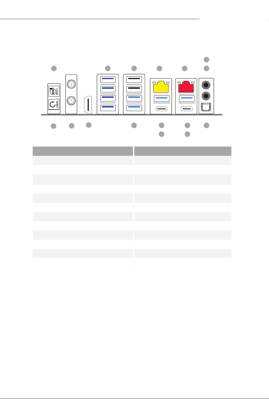
1.4 I/O Panel
No. Description No. Description
1 BIOS Flashback Button 10 USB4 Type-C Port
2 USB 3.2 Gen1 Type-A Ports (USB4_TC2)****
(USB32_1234)* 11 USB 3.2 Gen2 Type-A Port
3 USB 2.0 Ports (USB_12) (USB32_7)
4 5G LAN RJ-45 Port 12 USB4 Type-C Port
(Realtek RTL8126)** (USB4_TC1)****
5 10G LAN RJ-45 Port 13 USB 3.2 Gen1 Type-A Ports
(Marvell (Aquantia) AQC113)*** (USB32_56)
6 Microphone Input Jack*** 14 HDMI Port
7 Line Out Jack*** 15 Antenna Ports
8 Optical SPDIF Out Port 16 Clear CMOS button
9 USB 3.2 Gen2 Type-A Port (USB32_8)
16
11
8
15
721
6
12
14
3
13
5
9
10
4
10
* Ultra USB Power is supported on USB32_1234 ports. ACPI wake-up function is not supported on USB32_34
ports.
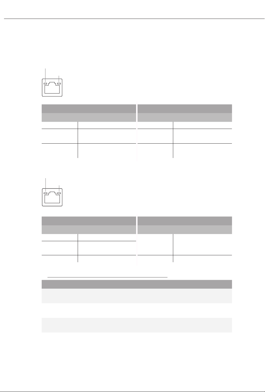
**ere are two LEDs on each LAN port. Please refer to the table below for the LAN port LED indications.
Activity / Link LED Speed LED
Status Description Status Description
O No Link O 10Mbps connection
Blinking Data Activity Orange 100Mbps/1Gbps/2.5
connection
On Link Green 5Gbps connection
connection
*** ere are two LEDs on each LAN port. Please refer to the table below for the LAN port LED indications.
Activity / Link LED Speed LED
Status Description Status Description
O No Link
Orange
100Mbps/1Gbps/2.5Gbps
/5Gbps connection
Blinking Data Activity
On Link Green 10Gbps connection
*** Function of the Audio Ports in 2, 4, 5.1 or 7.1-channel Conguration:
Channel Port Function
2ch
Line Out Jack
(Rear Panel)
Front speaker out
4ch
Pink-Mic
(Front Panel)
Rear speaker out
5.1ch
Microphone Input Jack
(Rear Panel)
Central/Subwoofer speaker out
7.1ch
Lime-Headphone
(Front Panel)
Side Speaker out
**** USB4 controller(for USB4_TC1 and USB4_TC2) will run at Gen4x2 with with 8000 (Phoenix 2) series
processors.
ACT/LINK LED
SPEED LED
LAN Port
ACT/LINK LED
SPEED LED
LAN Port
11
X870 Taichi Creator
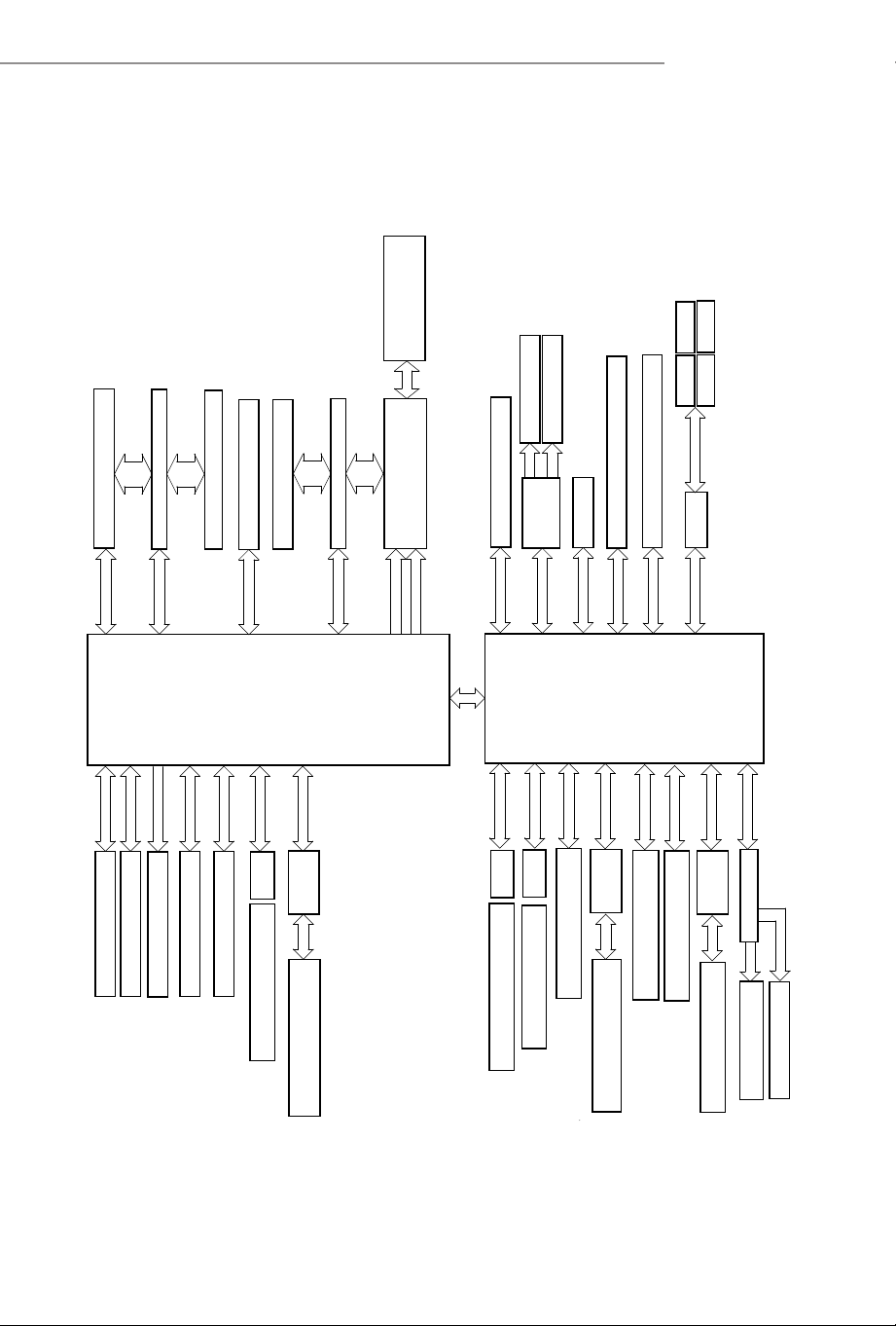
1.5 Block Diagram
Channel B
Channel A
DDR5 Slot x2
DDR5 Slot x2
SPI
eSPI
Flash ROM
PCE1 (PCIe Gen5 x16 Slot) (x16/x8)
PCIe Gen5 x4
M.2_1(PCIe Gen5 x4 )
PCIe Gen4 x4 BUS
Rear USB 3.2 Gen2 *1 port
AMD X870 Chipset
AMD AM5
Processor
LGA1718
20Gb/s
DP0
HDMI Port
Front USB 2.0 *2 ports
ASMedia USB4 host controller
(ASM4242)
x4
Front USB 3.2 Gen2x2 Type C *1 port
Front USB 3.2 Gen1 *4 ports
(USB32_56)
Realtek ALC4082
Front panel Audio header
USB3.2 G1
x1
WiFi key E
x1
Realtek 8126 (5G Ethernet controller)
USB3.2 G2x2
10Gb/sUSB3.2 G2
5Gb/s
480Mb/s
480Mb/s
USB2.0
USB2.0
SATA3_A1
SATA3_A2
SATA3_A3
SATA3_A4
PCIe GEN4
SATA 6Gb/s
PCIe GEN4
PCIe GEN4
USB3.2 G2 10Gb/s
SIO NCT6686D
PCIE2 (PCIe Gen5 x8 Slot) (x0/x8)
DP1
DP2
Rear USB4 Type C *2ports
2+1 Audio
USB3.2 G1 5Gb/s
Rear USB 3.2 Gen1 *2 ports
Rear USB 2.0 *2 ports
480Mb/sUSB2.0
M.2_3 (PCIe Gen4 x4)
PCIe
PCIe Switch + Redriver
PCIe
PCIe Gen5 x4
M2_2 (PCIe Gen5 x4)
Gen5 x4
Gen4 x4
PCIe
PCIe Switch + Redriver
Gen5 x8
PCIe
Gen5 x8
PCIe Gen5 x8
PCIe Gen5 x8
ReDriver
Rear USB 3.2 Gen2 Type A *1 port
ASM1074
USB3.0 HUB
USB3.2 G1
Rear USB 3.2 Gen1 Type A *4 ports
5Gb/s
(USB32_8)
(USB32_1234)
PCIE3(PCIe Gen3 x4)
PCIe Gen3
M2_4(PCIe Gen3 x4)
PCIe Switch
Aquantia AQC113 (10G Ethernet controller)
x1PCIe GEN4
x1PCIe GEN4
ASM1164
x4
ReDriver
(USB32_7)
(USB32_TC1)
ASM1074
USB3.0 HUB
(USB32_9_10,USB32_11_12)
(USB_12)
(USB2_7_8)
(USB2_3_4,USB2_5_6)
Front USB 2.0 *4 ports
480Mb/sUSB2.0
GL852
USB2.0 HUB
(USB4_TC1,USB4_TC2)
ReDriver

12
1.6 802.11be Wi-Fi 7 Module and ASRock WiFi 2.4/5/6 GHz
Antennas
802.11be Wi-Fi 7 + BT Module
is motherboard comes with an exclusive 802.11 a/b/g/n/ac/ax/be Wi-Fi 7 + BT v5.4
module that oers support for 802.11 a/b/g/n/ac/ax/be Wi-Fi 7 connectivity standards
and Bluetooth v5.4. Wi-Fi 7 + BT module is an easy-to-use wireless local area network
(WLAN) adapter to support Wi-Fi 7 + BT. Bluetooth v5.4 standard features Smart
Ready technology that adds a whole new class of functionality into the mobile devices.
* e transmission speed may vary according to the environment.
* e Wi-Fi 7 module is supported by Microso® Windows® 11 only. ere is no
driver available for Windows® 10. e availability of the 6GHz band will depend on
the dierent regulation status of each country and region. It will be activated (for
supported countries) through Windows® Update and soware updates once available.

13
X870 Taichi Creator
is is an ATX form factor motherboard. Before you install the motherboard, study
the conguration of your chassis to ensure that the motherboard ts into it.
Pre-installation Precautions
Take note of the following precautions before you install motherboard components
or change any motherboard settings.
•
Make sure to unplug the power cord before installing or removing the motherboard
components. Failure to do so may cause physical injuries and damages to motherboard
components.
•
In order to avoid damage from static electricity to the motherboard’s components,
NEVER place your motherboard directly on a carpet. Also remember to use a grounded
wrist strap or touch a safety grounded object before you handle the components.
•
Hold components by the edges and do not touch the ICs.
•
Whenever you uninstall any components, place them on a grounded anti-static pad or
in the bag that comes with the components.
•
When placing screws to secure the motherboard to the chassis, please do not over-
tighten the screws! Doing so may damage the motherboard.
Chapter 2 Installation
14
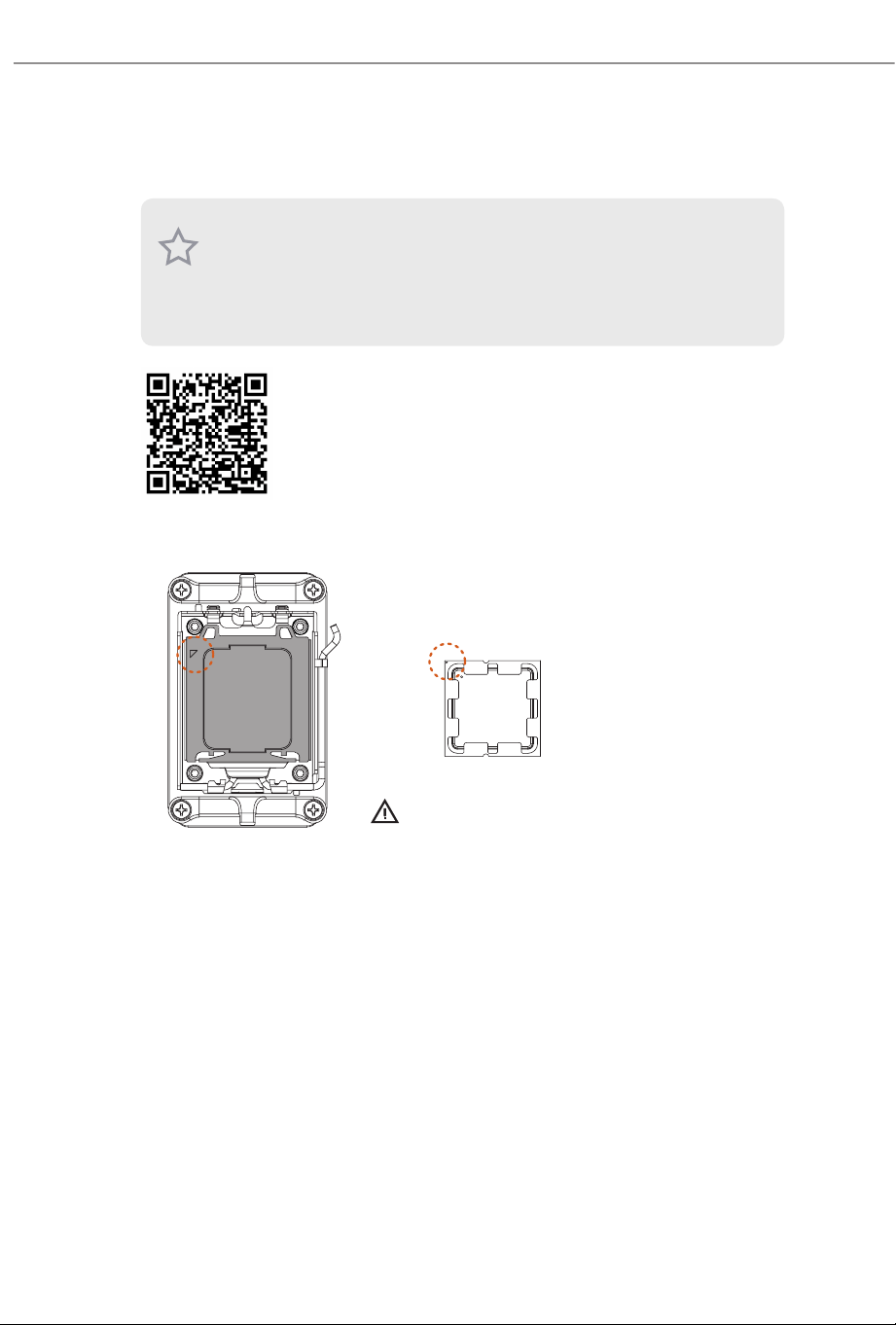
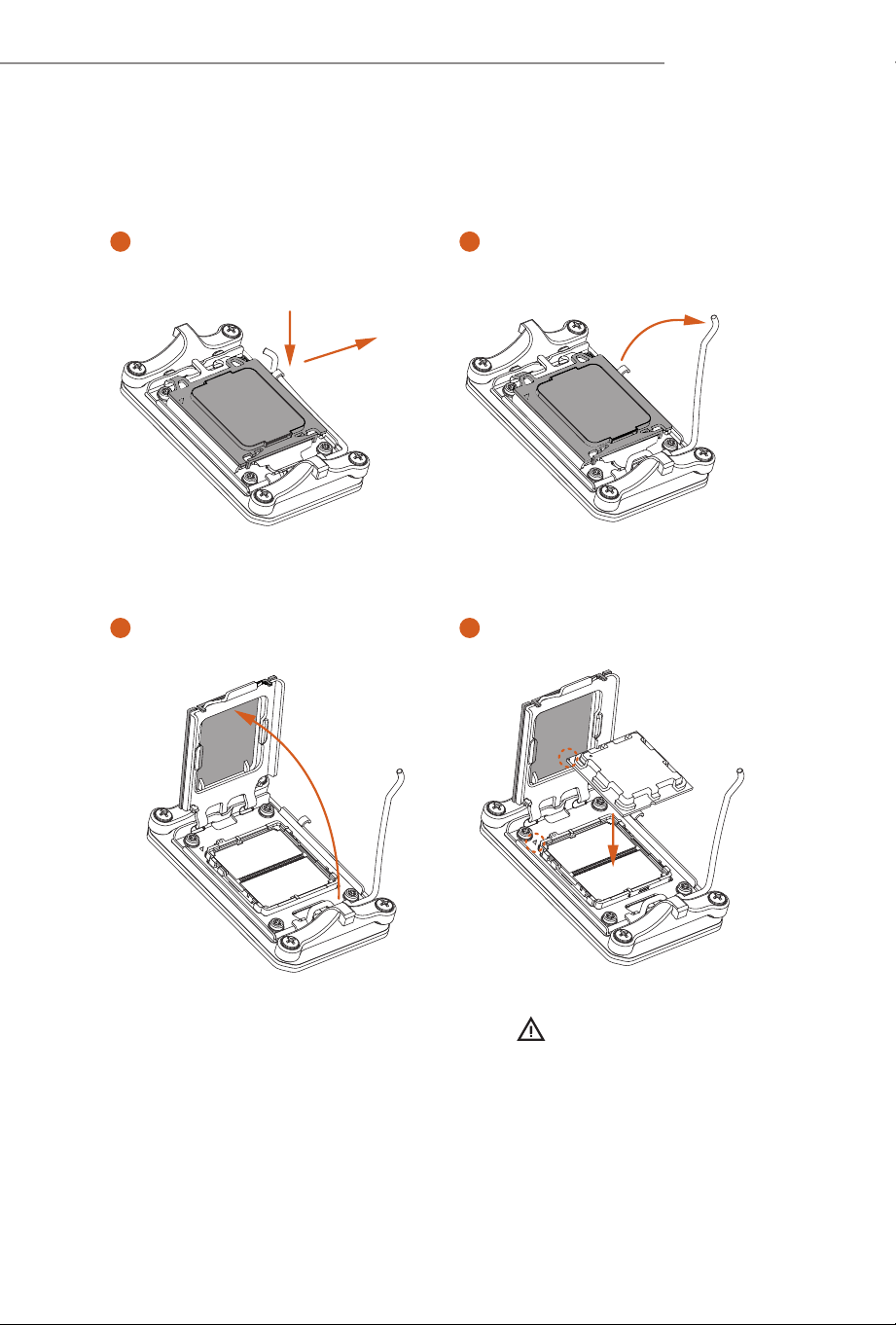
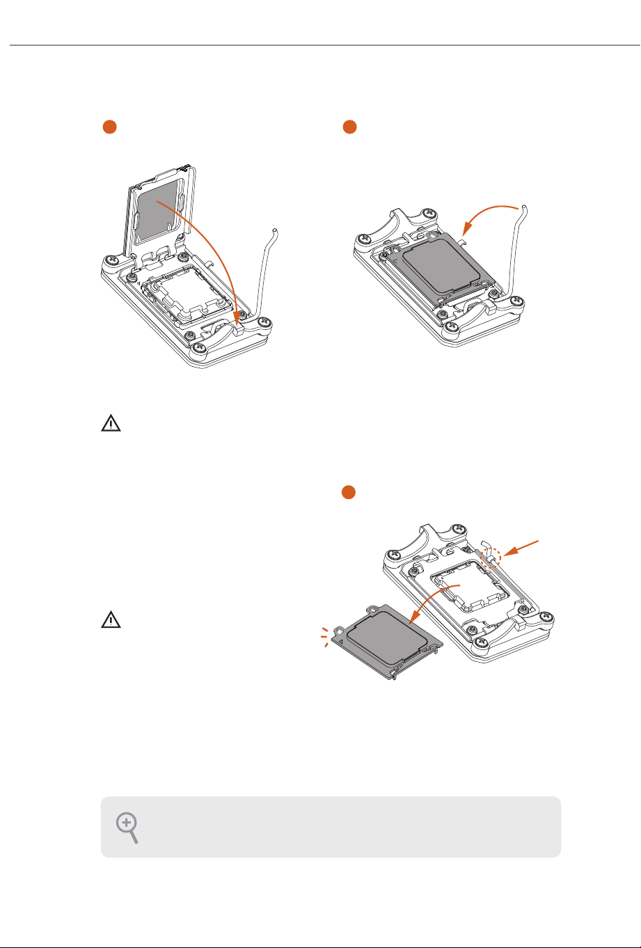
2.1 Installing the CPU
1. Before you insert the 1718-Pin CPU into the socket, please check if the PnP cap is on the
socket, if the CPU surface is unclean, or if there are any bent pins in the socket. Do not
force to insert the CPU into the socket if above situation is found. Otherwise, the CPU
will be seriously damaged.
2. Unplug all power cables before installing the CPU.
Tutorial Video
Turn your CPU to the correct orientation before opening
the CPU socket cover.
15
X870 Taichi Creator
Turn your CPU to the correct orientation before opening
the CPU socket cover.
Carefully place the CPU in as at as
possible. Do not drop it.
4
1
2
A
B
3
16
6
7
5
Please save the cover if the processor is removed. e cover must be placed if you wish to
return the motherboard for aer service.
Make sure the black cover plate
is always in place until it pops o
when closing the socket lever.
Make sure the CPU is aligned with the
socket before locking it into place.
17
X870 Taichi Creator
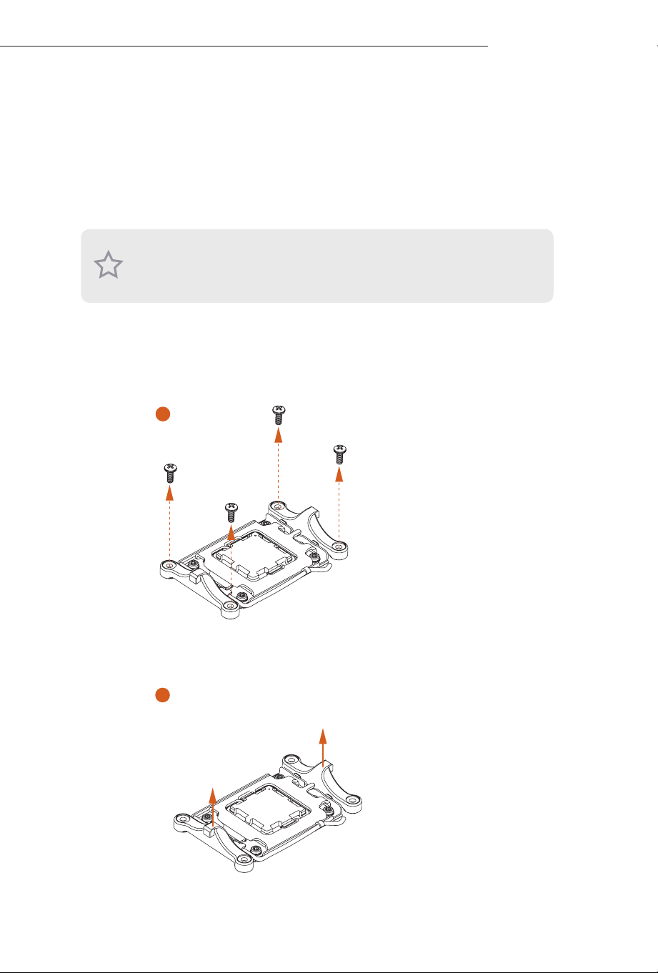
2.2 Installing the CPU Fan and Heatsink
Aer you install the CPU into this motherboard, it is necessary to install a larger
heatsink and cooling fan to dissipate heat. You also need to spray thermal grease
between the CPU and the heatsink to improve heat dissipation. Make sure that the
CPU and the heatsink are securely fastened and in good contact with each other.
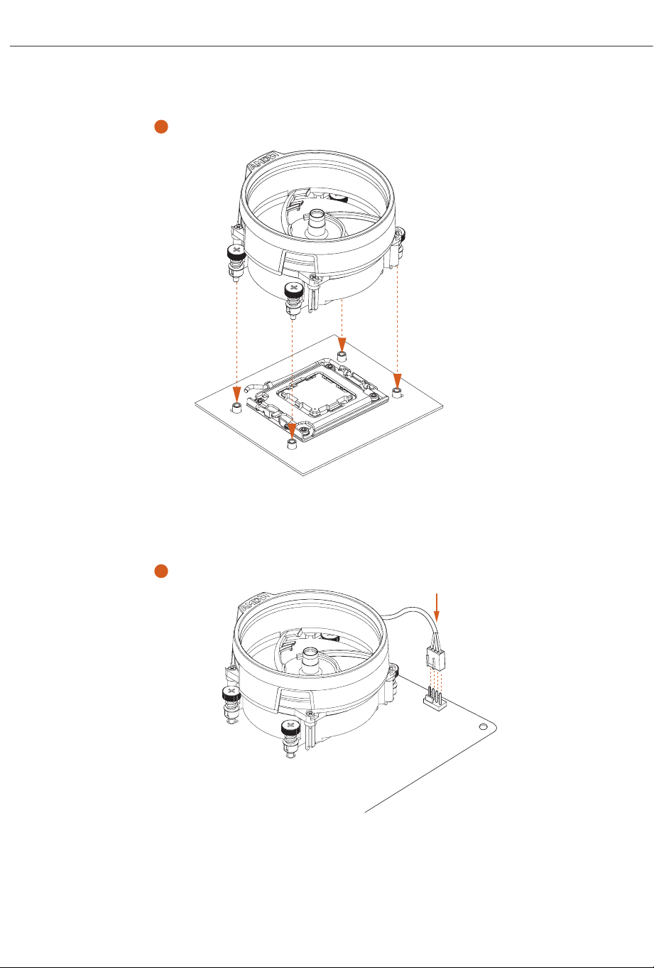
Installing the CPU Cooler (Type 1)
Please turn o the power or remove the power cord before changing a CPU or heatsink.
2
1
18
4
3
CPU_FAN1
19
X870 Taichi Creator
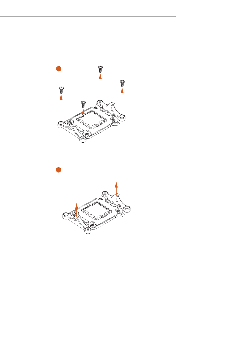
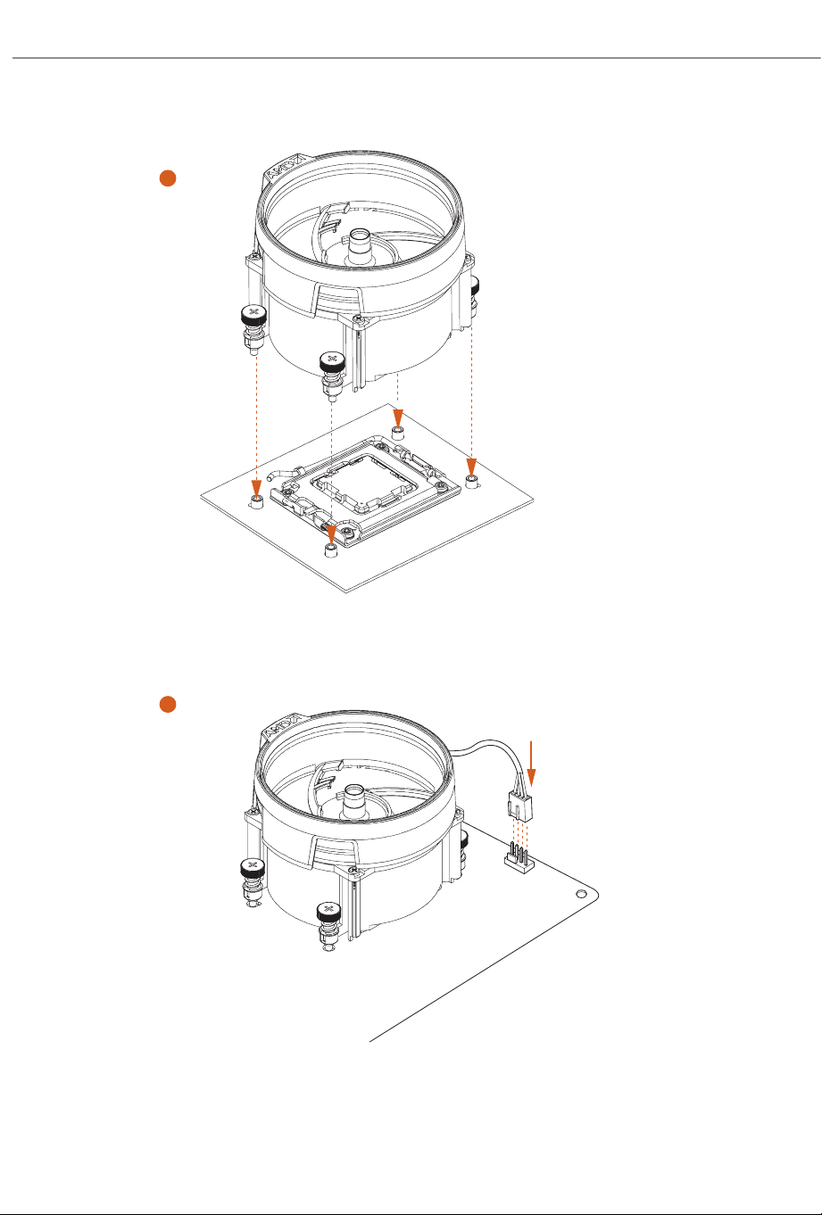
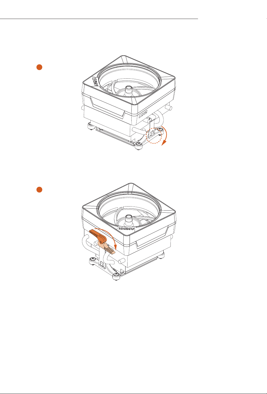
Installing the CPU Cooler (Type 2)
2
1
20
3
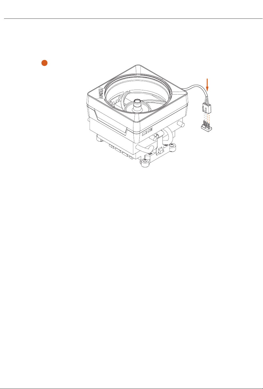
4
CPU_FAN1
21
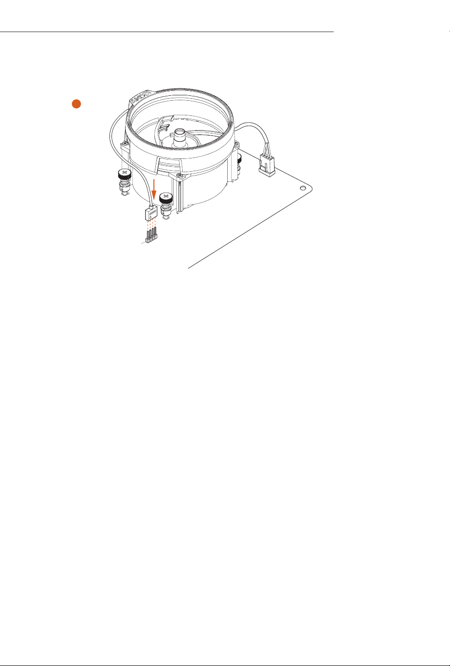
X870 Taichi Creator
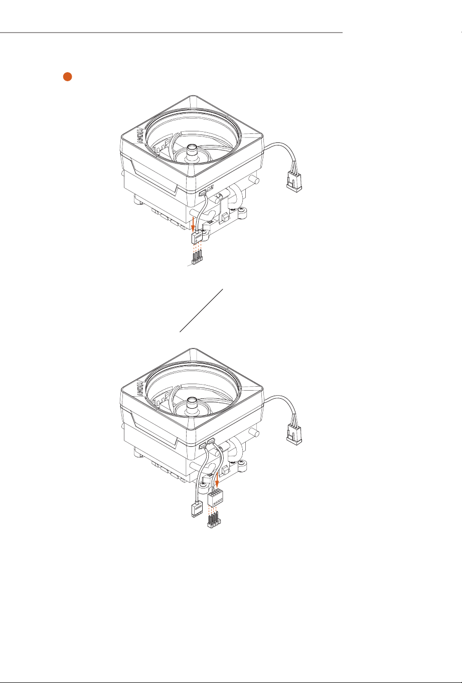
5
CPU_FAN1
RGB_LED1
*e illustrations shown here are for reference purposes only and may not exactly match
the model you purchase.
+12V
22
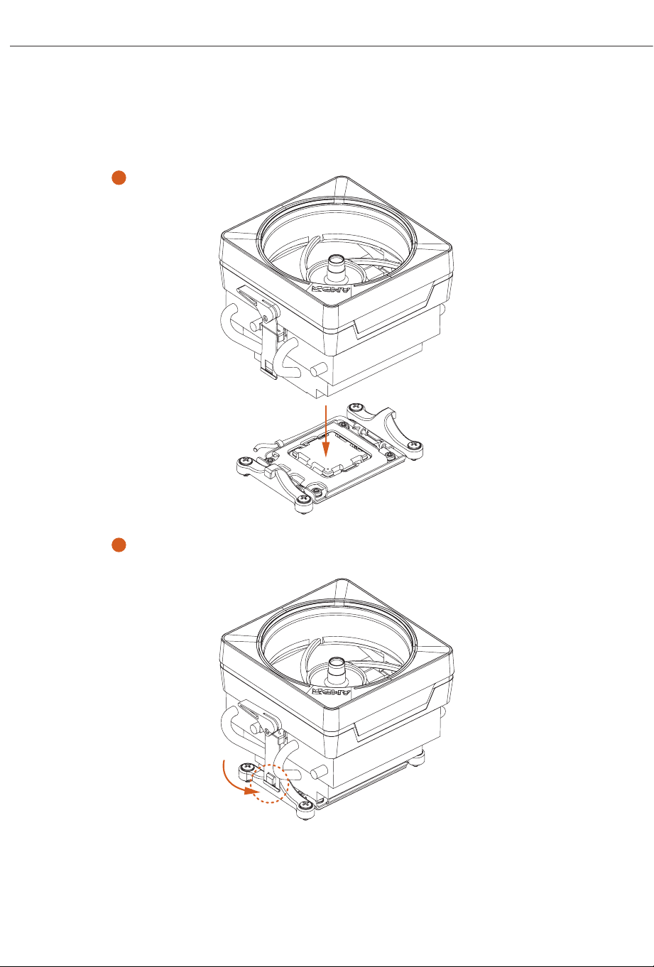
Installing the CPU Cooler (Type 3)
2
1
23
X870 Taichi Creator
4
3
24
5
CPU_F
AN1
25
X870 Taichi Creator
6
CPU_FAN1
RGB_LED1
CPU_FAN1
RGB_LED1
USB_1_2
Please note that only one cable should be used at a time in this step.
If you select RGB_LED1, please install ASRock utility "ASRock Polychrome SYNC".
If you select USB connector, please install AMD utility "SR3 Settings Soware".
*e illustrations shown here are for reference purposes only and may not exactly match
the model you purchase.
+12V
or
26
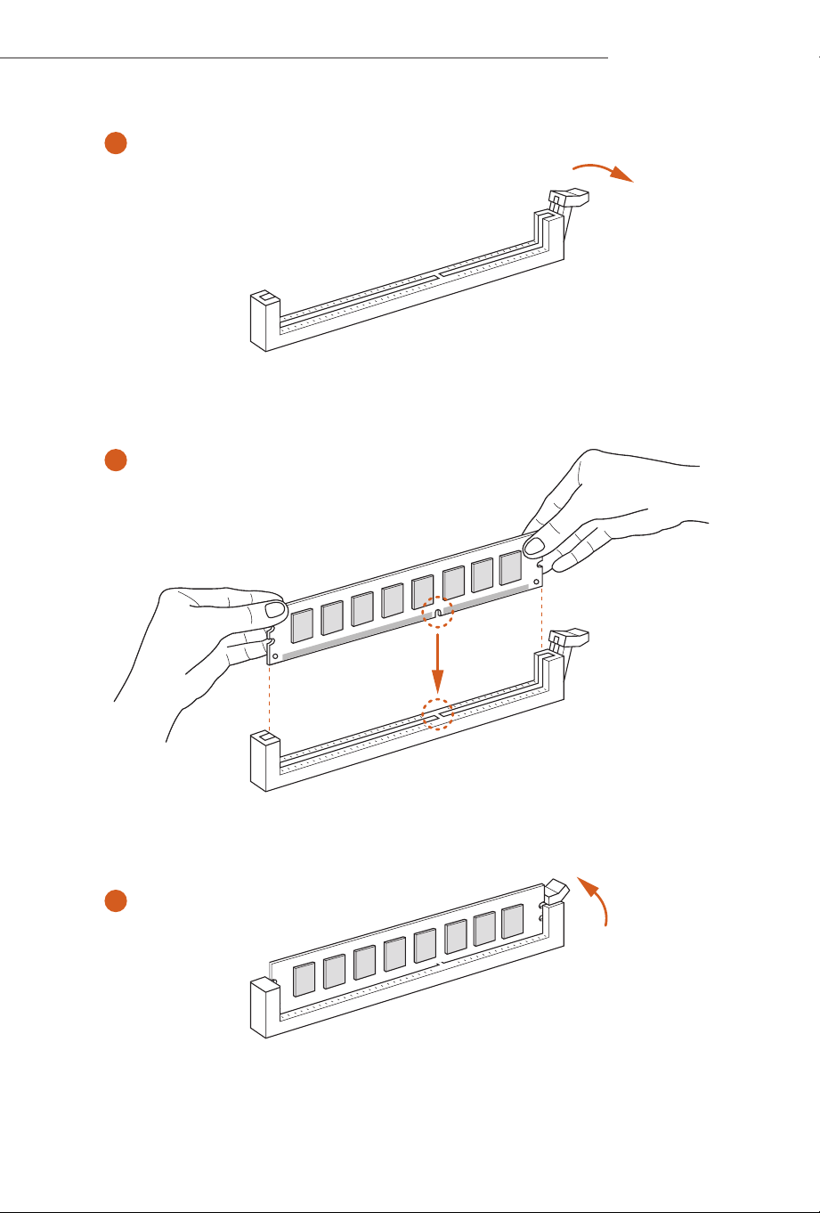
2.3 Installing Memory Modules (DIMM)
is motherboard provides four 288-pin DDR5 (Double Data Rate 5) DIMM slots,
and supports Dual Channel Memory Technology.
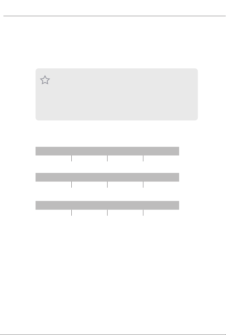
Recommended Memory Conguration
1 DIMM
2 DIMMs
4 DIMMs
A1 A2 B1 B2
V
A1 A2 B1 B2
V V
A1 A2 B1 B2
V V V V
1. For dual channel conguration, you always need to install identical (the same brand,
speed, size and chip-type) DDR5 DIMM pairs.
2. It is unable to activate Dual Channel Memory Technology with only one or three memory
module installed.
3. It is not allowed to install a DDR, DDR2 , DDR3 or DDR4 memory module into a DDR5
slot; otherwise, this motherboard and DIMM may be damaged.
4. e DIMM only ts in one correct orientation. It will cause permanent damage to the
motherboard and the DIMM if you force the DIMM into the slot at incorrect orientation.
27
X870 Taichi Creator
1
2
3
28
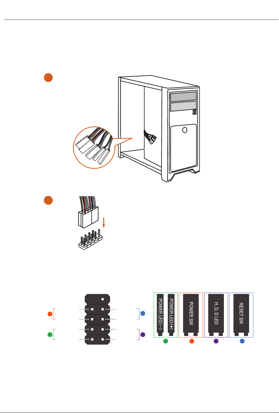
2.4 Connecting the Front Panel Header
ABC D
1
2
32:(56:
5(6(76:
32:(5/('
32:(5/('
+''/('
3$1(/
Power SW (-) RESET SW (+)
HDD LED (-)
HDD LED (+)
12
910
RESET SW (-)Power SW (+)
Power LED (-)
Power LED (+)
A
B
C
D
PANEL1
HDD LED
RESET SW
System Panel Header
Front Panel Wires
29
X870 Taichi Creator
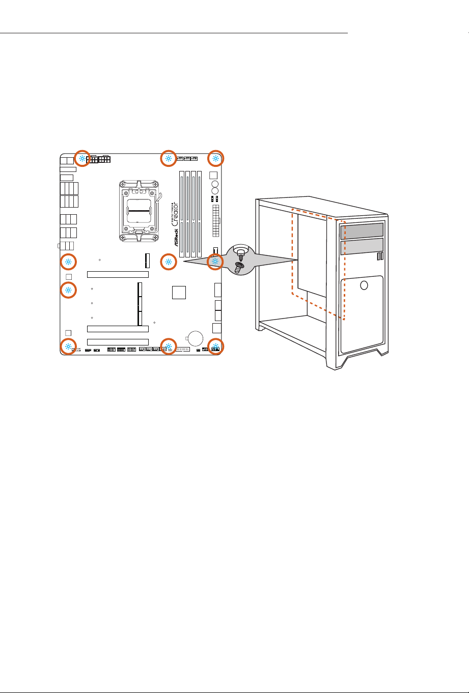
2.5 Installing the Motherboard
30
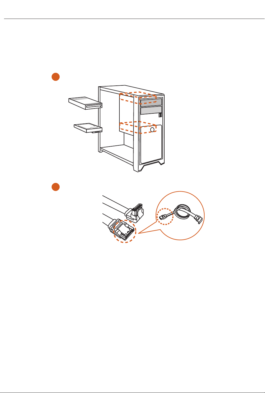
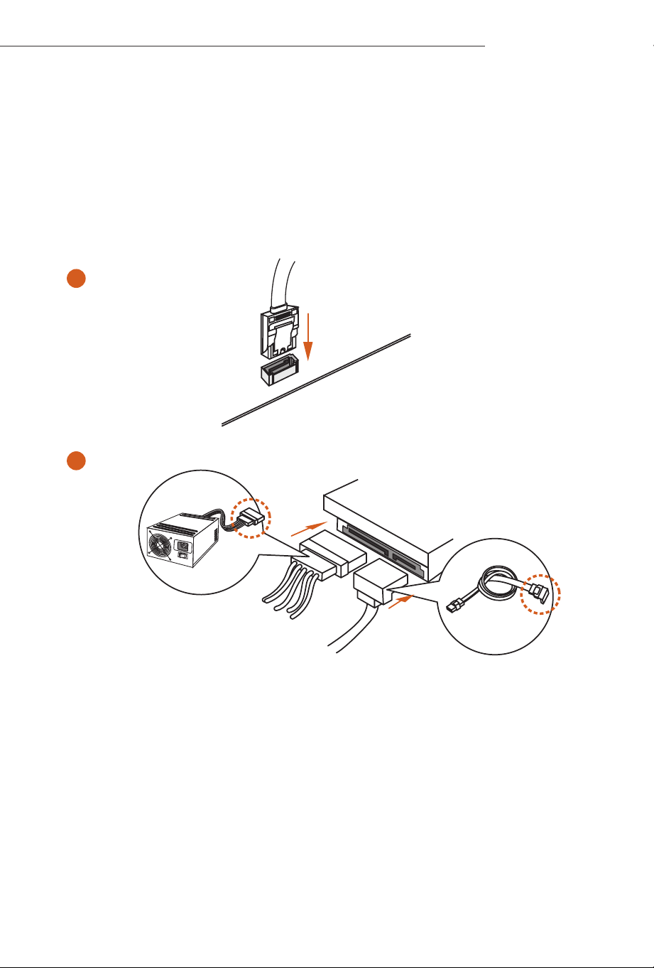
2.6 Installing SATA Drives
1
2
Optical Drive
SATA Drive
SATA Data Cable
31
X870 Taichi Creator
3
4
SATA Power Connector
SATA Data Connector
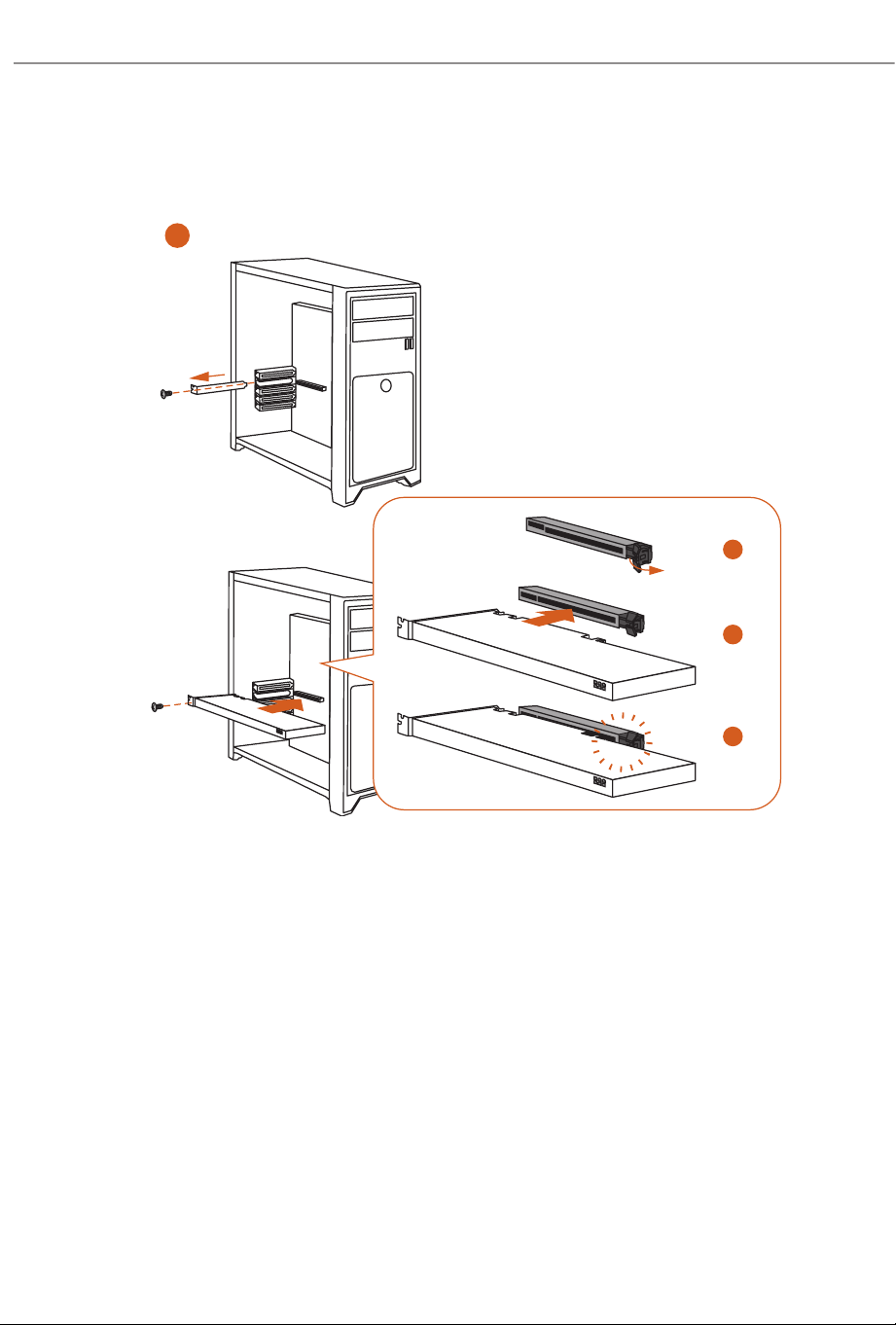
32
Skip Step 2 if you install a graphics card into PCIE1 slot. Illustrations here are
examples only.
1
1
CLICK!
2
3
4
2.7 Installing a Graphics Card
33
X870 Taichi Creator
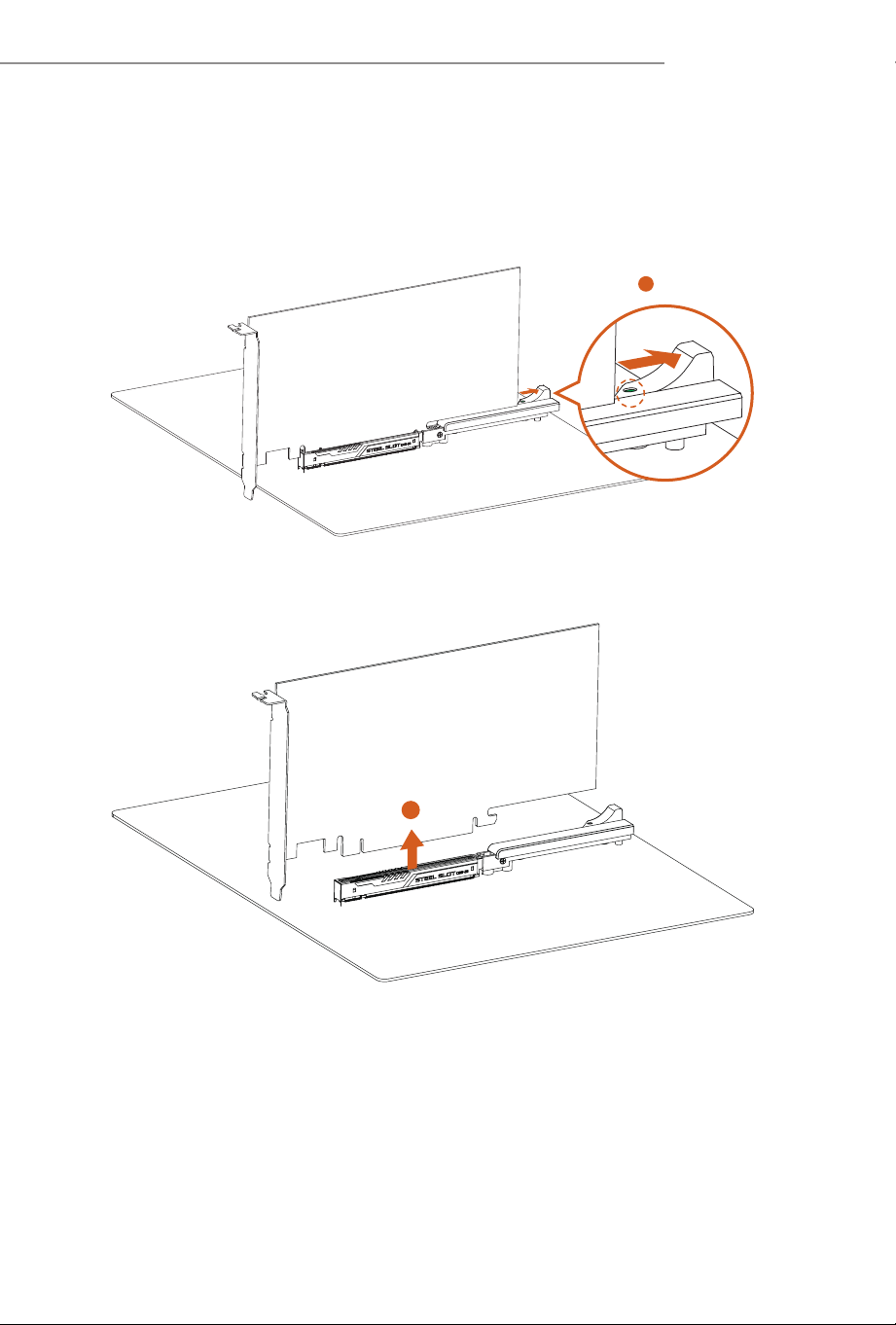
Removing a Graphics Card from PCIE1 Slot
Please follow the steps below to release the PCIe slot latch on PCIE1 and remove the
graphics card.
EZ RELEASE
1
1. Slide the latch to the right to release the graphics card from the PCIe slot.
Green indicator shows that the latch is properly released.
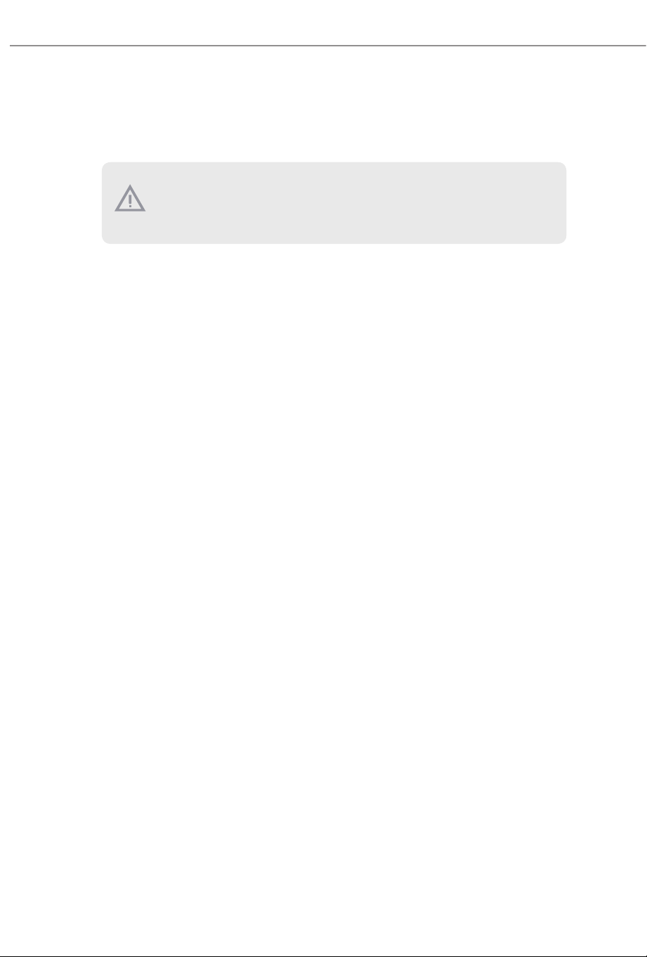
EZ RELEASE
2
2. You can now easily remove the graphics card from the PCIe slot.
*Please ensure that the system power cable is removed when removing the graphics
card.
34
Expansion Slots (PCIe Slots)
ere are 3 PCI Express slots on the motherboard.
PCIe slots:
PCIE1 (PCIe 5.0 x16 slot) is used for PCIe x16 lane width graphics cards.
PCIE2 (PCIe 5.0 x16 slot) is used for PCIe x16 lane width graphics cards.
PCIE3 (PCIe 3.0 x16 slot) is used for PCIe x4 lane width graphics cards.
* PCIE1 will run at Gen5x16 with 9000 and 7000 series processors, Gen4x8 with
8000 (Phoenix 1) series processors and Gen4x4 with 8000 (Phoenix 2) series
processors.
* If M2_4 is occupied, both PCIE3 and M2_4 will downgrade to x2 mode.
Before installing an expansion card, please make sure that the power supply is switched o
or the power cord is unplugged. Please read the documentation of the expansion card and
make necessary hardware settings for the card before you start the installation.
35
X870 Taichi Creator
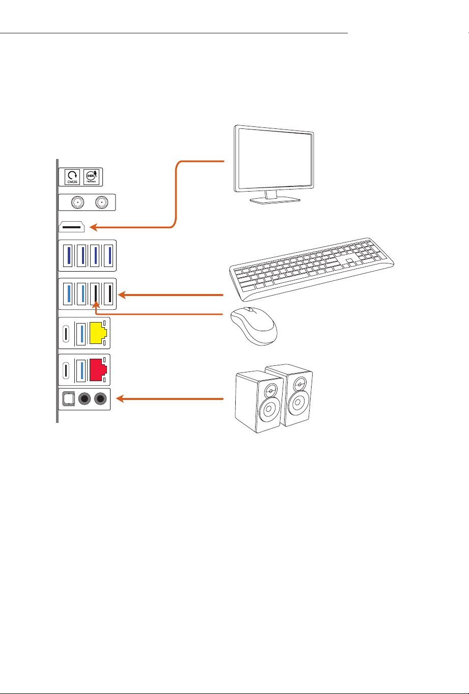
2.8 Connecting Peripheral Devices
36
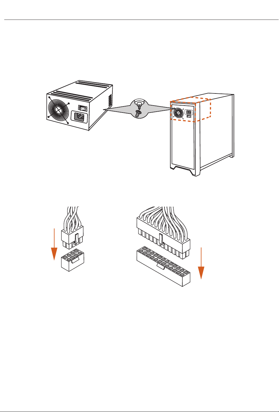
2.9 Connecting the Power Connectors
$7;3:5
$7;9
37
X870 Taichi Creator
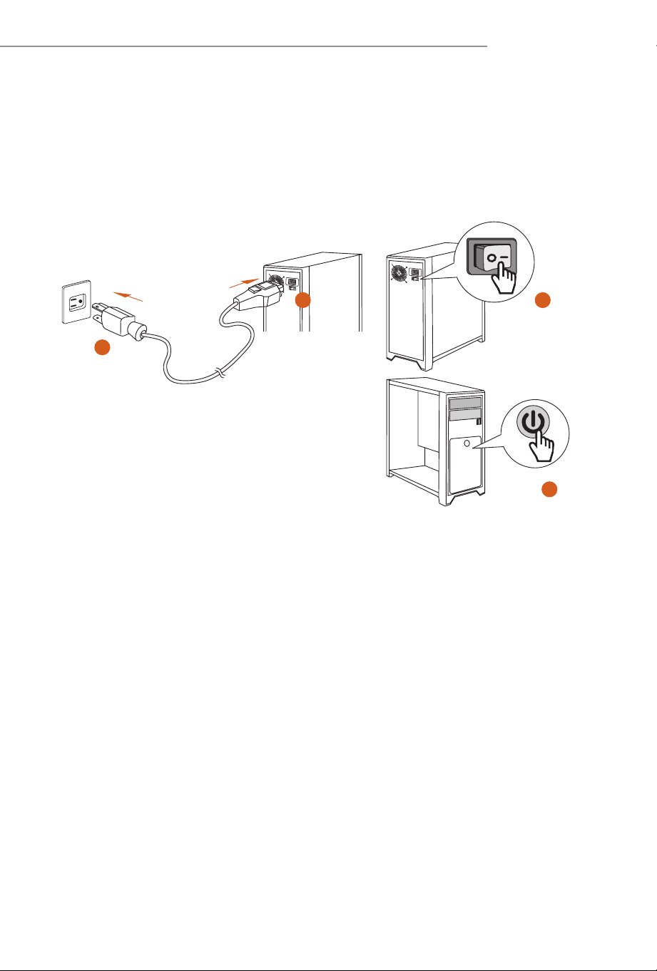
2.10 Power On
2
3
4
1
38
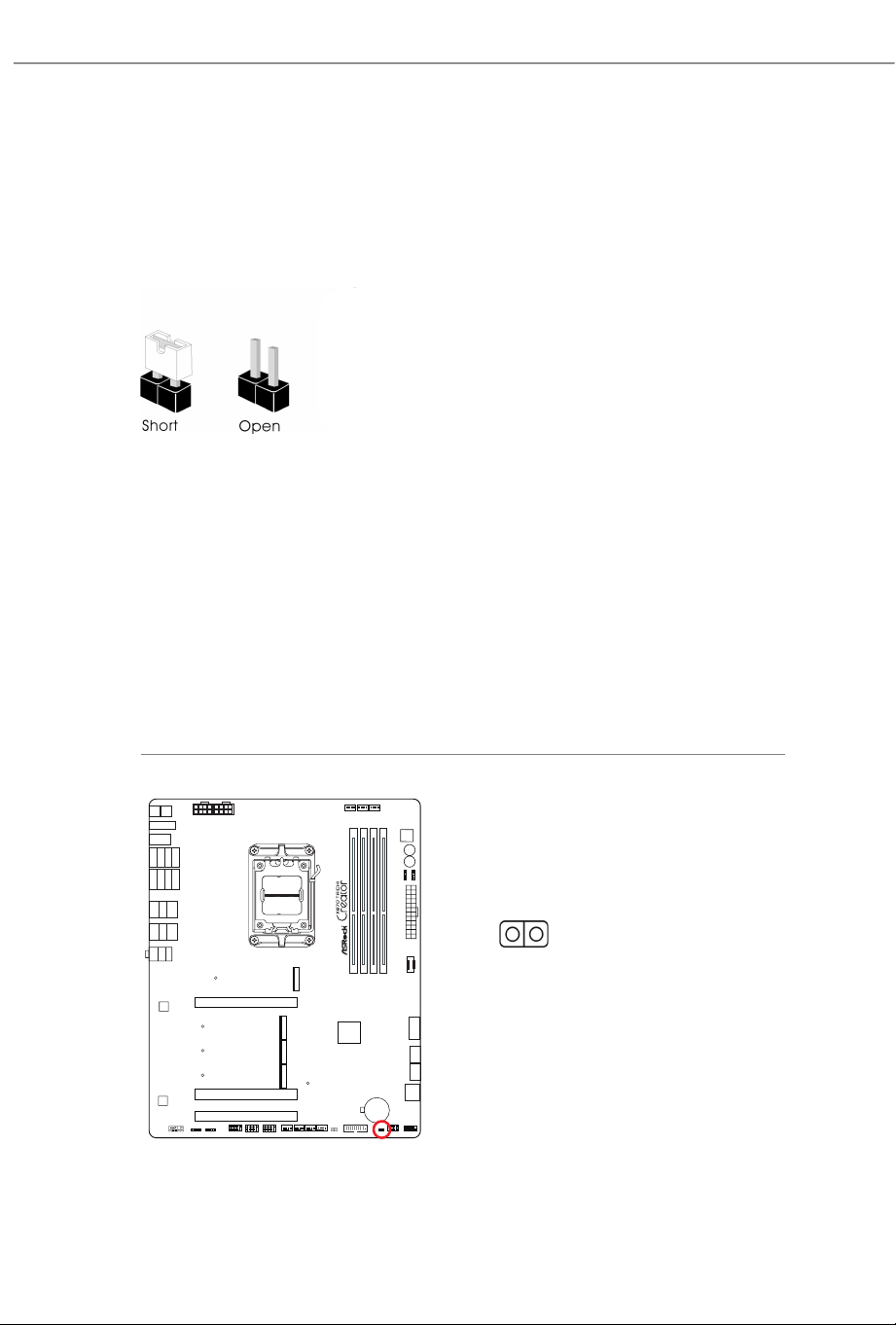
2.11 Jumpers Setup
e illustration shows how jumpers are setup. When the jumper cap is placed on
the pins, the jumper is “Short”. If no jumper cap is placed on the pins, the jumper is
“Open”.
Clear CMOS Jumper
(CLRCMOS1) (see p.7, No. 20)
CLRCMOS1 allows you to clear the data in CMOS. e data in CMOS includes
system setup information such as system password, date, time, and system setup
parameters. To clear and reset the system parameters to default setup, please
turn o the computer and unplug the power cord, then use a jumper cap to short
the pins on CLRCMOS1 for 3 seconds. Please remember to remove the jumper
cap aer clearing the CMOS. If you need to clear the CMOS when you just nish
updating the BIOS, you must boot up the system rst, and then shut it down
before you do the clear-CMOS action.
CLRCMOS1
2-pin Jumper
Short: Clear CMOS
Open: Default
39
X870 Taichi Creator
2.12 Onboard Headers and Connectors
System Panel Header
(9-pin PANEL1) (see p.7, No. 18)
Connect the power button, reset button and system status indicator on the chassis
to this header according to the pin assignments below. Note the positive and
negative pins before connecting the cables.
PANEL1
Onboard headers and connectors are NOT jumpers. Do NOT place jumper caps over these
headers and connectors. Placing jumper caps over the headers and connectors will cause
permanent damage to the motherboard.
PWRBTN (Power Button):
Connect to the power button on the chassis front panel. You may congure the way to turn
o your system using the power button.
RESET (Reset Button):
Connect to the reset button on the chassis front panel. Press the reset button to restart the
computer if the computer freezes and fails to perform a normal restart.
PLED (System Power LED):
Connect to the power status indicator on the chassis front panel. e LED is on when the
system is operating. e LED keeps blinking when the system is in S1/S3 sleep state. e
LED is o when the system is in S4 sleep state or powered o (S5).
HDLED (Hard Drive Activity LED):
Connect to the hard drive activity LED on the chassis front panel. e LED is on when the
hard drive is reading or writing data.
e front panel design may dier by chassis. A front panel module mainly consists of power
button, reset button, power LED, hard drive activity LED, speaker and etc. When connect-
ing your chassis front panel module to this header, make sure the wire assignments and the
pin assignments are matched correctly.
GND
R ESET#
PWRBTN#
PLED-
PLED+
GND
HDLED-
HDLED+
1
GND
40
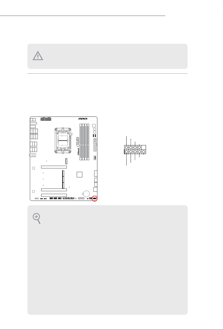
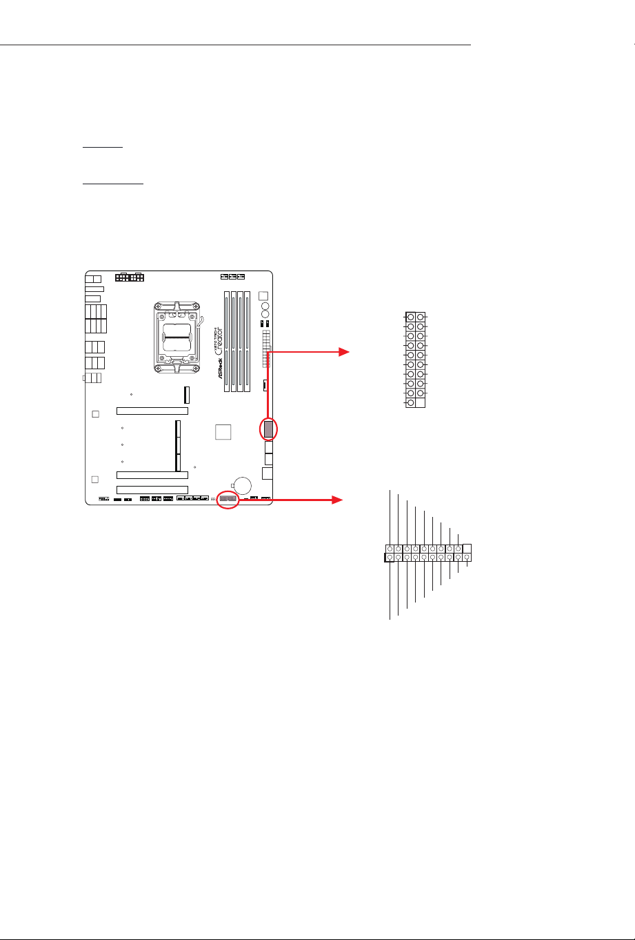
Power LED and Speaker Header
(7-pin SPK_PLED1) (see p.7, No. 19)
Please connect the chassis power LED and the chassis speaker to this header.
SPK_PLED1
1
+5V
DUMMY
PLED+
PLED+
PLED-
DUMMY
SPEAKER
41
X870 Taichi Creator
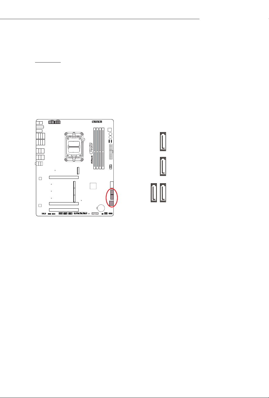
Serial ATA3 Connectors
Right Angle:
(SATA3_A1) (see p.7, No. 15)
(SATA3_A2) (see p.7, No. 16)
(SATA3_A3) (see p.7, No. 17)(Lower)
(SATA3_A4) (see p.7, No. 17)(Upper)
ese four SATA3 connectors support SATA data cables for internal storage
devices with up to 6.0 Gb/s data transfer rate.
SATA3_A2 SATA3_A1
SATA3_A4
SATA3_A3
42
USB 2.0 Headers
(9-pin USB_3_4) (see p.7, No. 29)
(9-pin USB_5_6) (see p.7, No. 28)
(9-pin USB_7_8) (see p.7, No. 27)
ere are three headers on this motherboard. Each USB 2.0 header can support
two ports.
USB_3_4
USB_5_6
USB_7_ 8
DUMMY
GND
GND
P+
P-
USB_PWR
P+
P-
USB_PWR
1
DUMMY
GND
GND
P+
P-
USB_PWR
P+
P-
USB_PWR
1
DUMMY
GND
GND
P+
P-
USB_PWR
P+
P-
USB_PWR
1
43
X870 Taichi Creator
USB 3.2 Gen1 Headers
Ver tic al:
(19-pin USB32_9_10) (see p.7, No. 21)
Right Angle:
(19-pin USB32_11_12) (see p.7, No. 14)
ere are two headers on this motherboard. Each USB 3.2 Gen1 header can
support two ports.
USB32_11_12
USB32_9_10
1
IntA_PB_D+
Dummy
IntA_PB_D-
GND
IntA_PB_SSTX+
GND
IntA_PB_SSTX-
IntA_PB_SSRX+
IntA_PB_SSRX-
VbusV
VbusV
IntA_PA_SSRX-
IntA_P
A_SSRX+
GND
IntA_PA_SSTX-
IntA_P
A_SSTX+
GND
IntA_PA_D-
IntA_PA_D+
1
ID
IntA_P_D+
IntA_P_D-
GND
IntA_P_SSTX+
IntA_P_SSTX-
GND
IntA_P_SSRX+
Vbus
IntA_P_D+
IntA_P_D-
GND
IntA_P_SSTX+
IntA_P_SSTX-
GND
IntA_P_SSRX+
IntA_P_SSRX-
Vbus
IntA_P_SSRX-
44
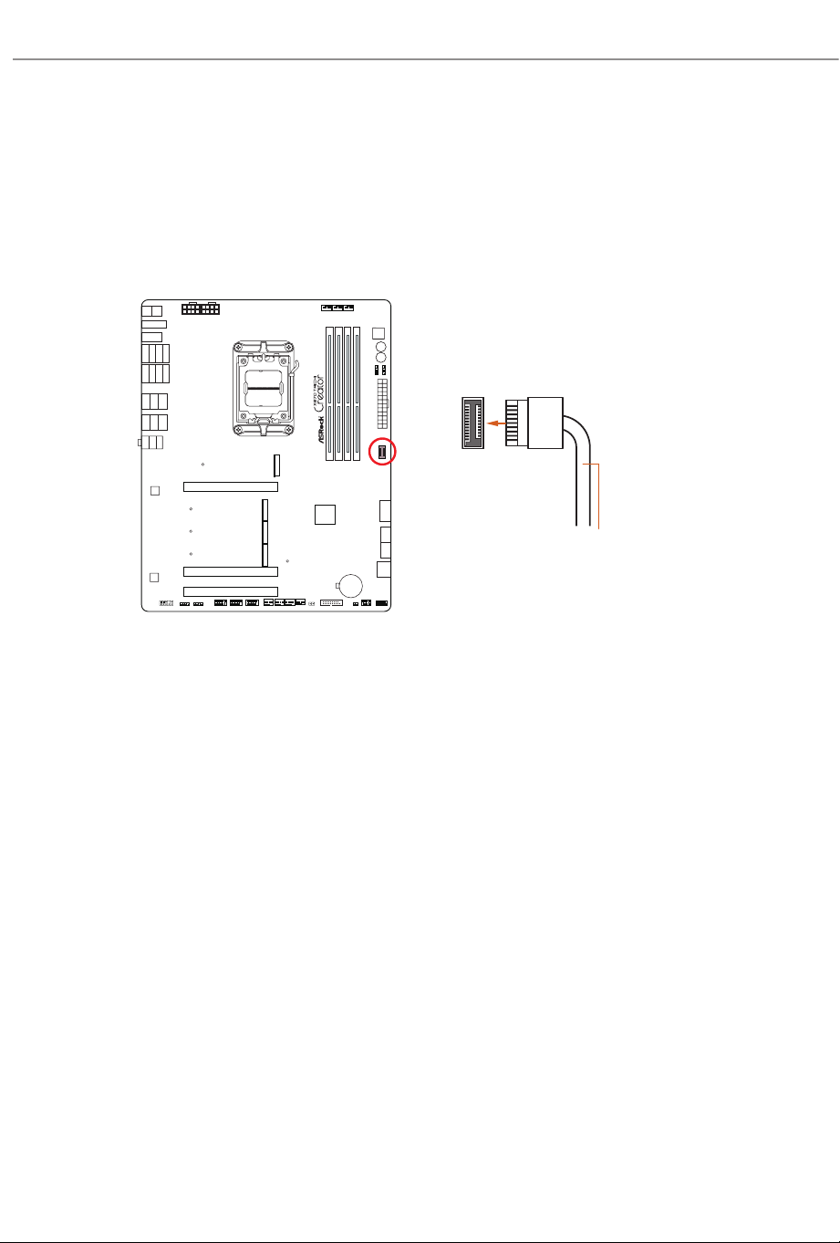
Front Panel Type C USB 3.2 Gen2x2 Header
(20-pin USB32_TC1) (see p.7, No. 13)
ere is one Front Panel Type C USB 3.2 Gen2x2 Header on this motherboard.
is header is used for connecting a USB 3.2 Gen2x2 module for additional USB 3.2
Gen2x2 ports.
USB32_TC1
USB Type-C Cable
45
X870 Taichi Creator
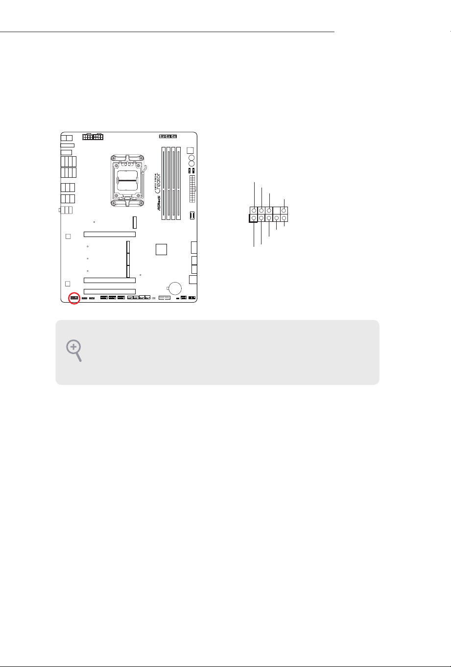
Front Panel Audio Header
(9-pin HD_AUDIO1) (see p.7, No. 32)
is header is for connecting audio devices to the front audio panel.
High Denition Audio supports Jack Sensing, but the panel wire on the chassis must sup-
port HDA to function correctly. Please follow the instructions in our manual and chassis
manual to install your system.
HD_AUDIO1
J_SENSE
OUT2_L
1
MIC_RET
PRESENCE#
GND
OUT2_R
MIC2_R
MIC2_L
OUT_RET
46
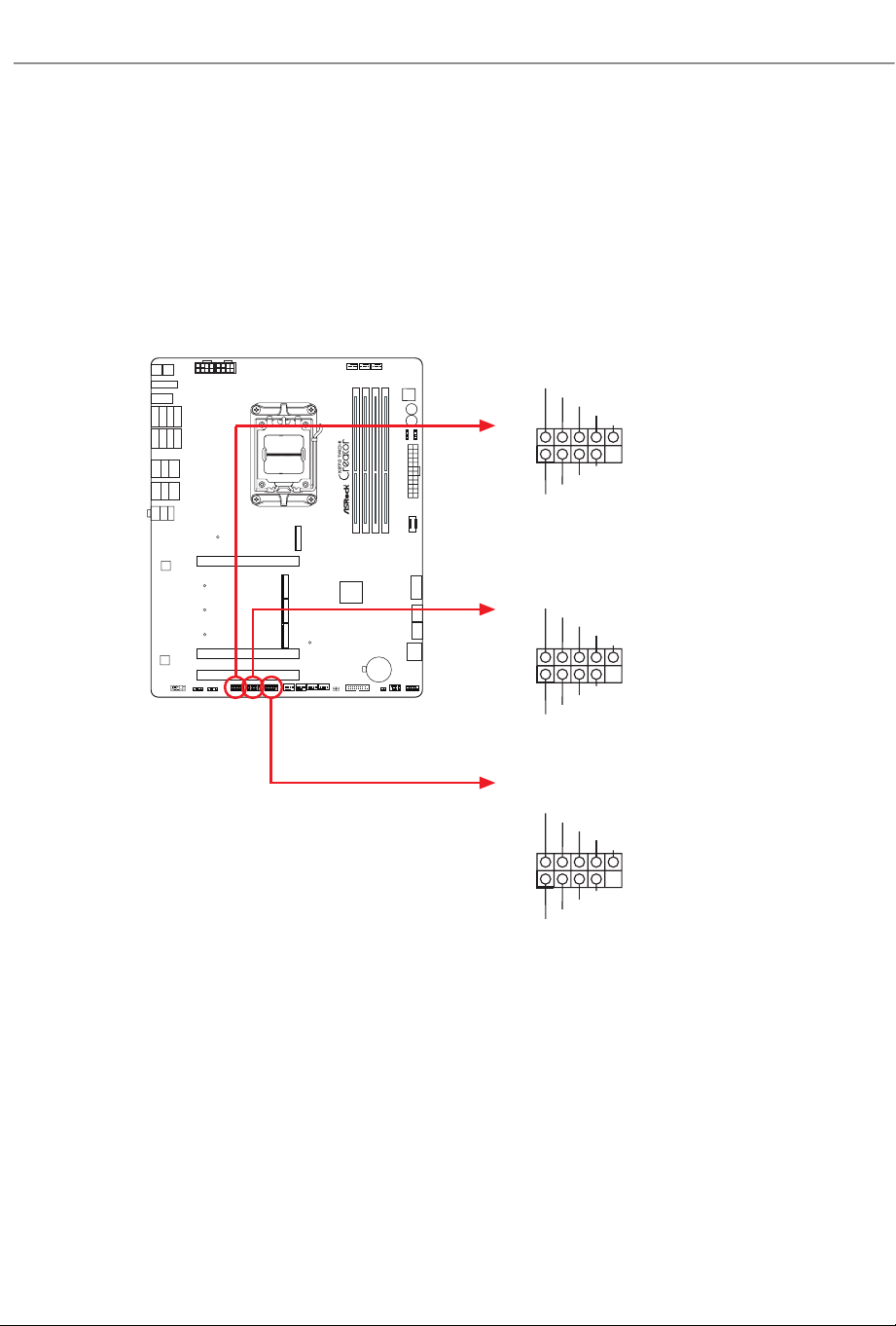
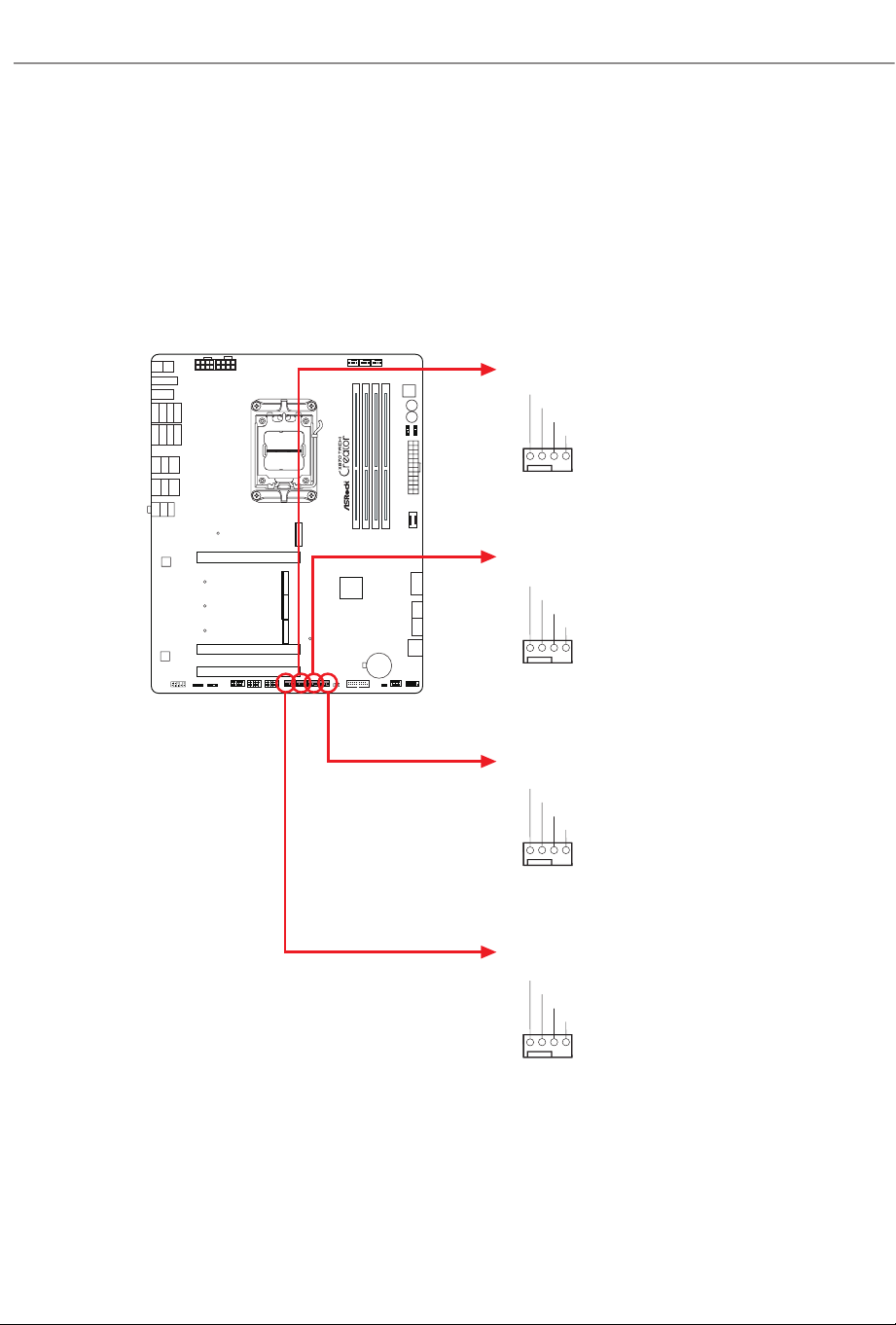
Chassis Fan Connectors
(4-pin CHA_FAN1) (see p.7, No. 23)
(4-pin CHA_FAN2) (see p.7, No. 24)
(4-pin CHA_FAN3) (see p.7, No. 25)
(4-pin CHA_FAN4) (see p.7, No. 26)
ese headers allow you to connect Case or Radiator fans. If you plan to connect a 3-pin
fan, please connect it to Pin 1-3.
CHA_FAN3
CHA_FAN2
CHA_FAN1
CHA_FAN4
GND
CHA_FAN_SPEED
FAN_SPEED_CONTRO
L
FAN_VOLTAGE
1 2 3 4
GND
CHA_FAN_SPEED
FAN_SPEED_CONTRO
L
FAN_VOLTAGE
1 2 3 4
GND
CHA_FAN_SPEED
FAN_SPEED_CONTRO
L
FAN_VOLTAGE
1 2 3 4
GND
CHA_FAN_SPEED
FAN_SPEED_CONTRO
L
FAN_VOLTAGE
1 2 3 4
47
X870 Taichi Creator
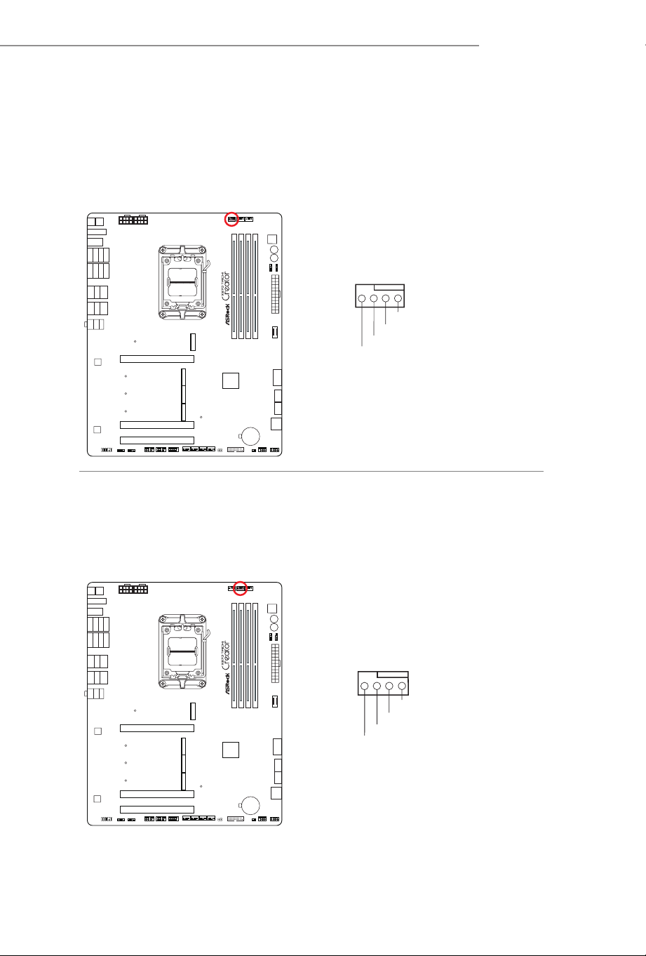
CPU Fan Connector
(4-pin CPU_FAN1) (see p.7, No. 3)
is header allows you to connect CPU fan. If you plan to connect a 3-pin fan,
please connect it to Pin 1-3.
CPU Fan Connector
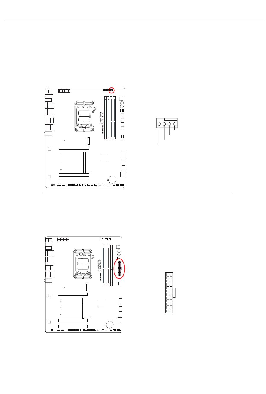
(4-pin CPU_FAN2) (see p.7, No. 5)
is header allows you to connect CPU fan or Water Pump. If you plan to connect
a 3-pin fan, please connect it to Pin 1-3.
CPU_FAN1
CPU_F
+12V
GND
AN_SPEED
FAN_SPEED_CONTROL
4 3 2 1
CPU_FAN2
CPU_F
FAN_VOLTAGE
GND
AN_SPEED
FAN_SPEED_CONTROL
4 3 2 1
48
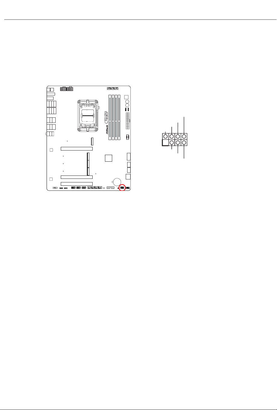
AIO Pump Fan Connector
(4-pin AIO_PUMP) (see p.7, No. 7)
is header allows you to connect AIO (All-in-One) pump or fan. If you plan to
connect a 3-pin AIO cooler fan, please connect it to Pin 1-3.
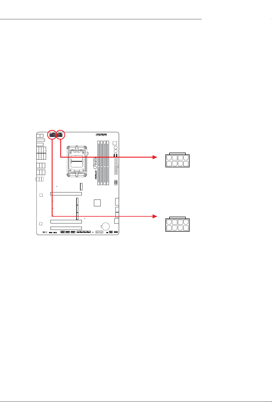
ATX Power Connector
(24-pin ATXPWR1) (see p.7, No. 12)
is motherboard provides a 24-pin ATX power connector. To use a 20-pin ATX
power supply, please plug it along Pin 1 and Pin 13.
AIO_PUMP
FAN_VOLTAGE
GND
AIO_PUMP_SPEED
FAN_SPEED_CONTROL
4 3 2 1
ATXPWR1
12
1
24
13
49
X870 Taichi Creator
ATX 12V Power Connectors
(8-pin ATX12V1) (see p.7, No. 1)
(8-pin ATX12V2) (see p.7, No. 2)
is motherboard provides two 8-pin ATX 12V power connectors. To use a 4-pin
ATX power supply, please plug it along Pin 1 and Pin 5.
*Connecting an ATX 12V 8-pin cable to ATX12V2 is optional.
*Warning: Please make sure that the power cable connected is for the CPU and
not the graphics card. Do not plug the PCIe power cable to this
connector.
ATX12V2
ATX12V1
4
1
8 5
4
1
8 5
50
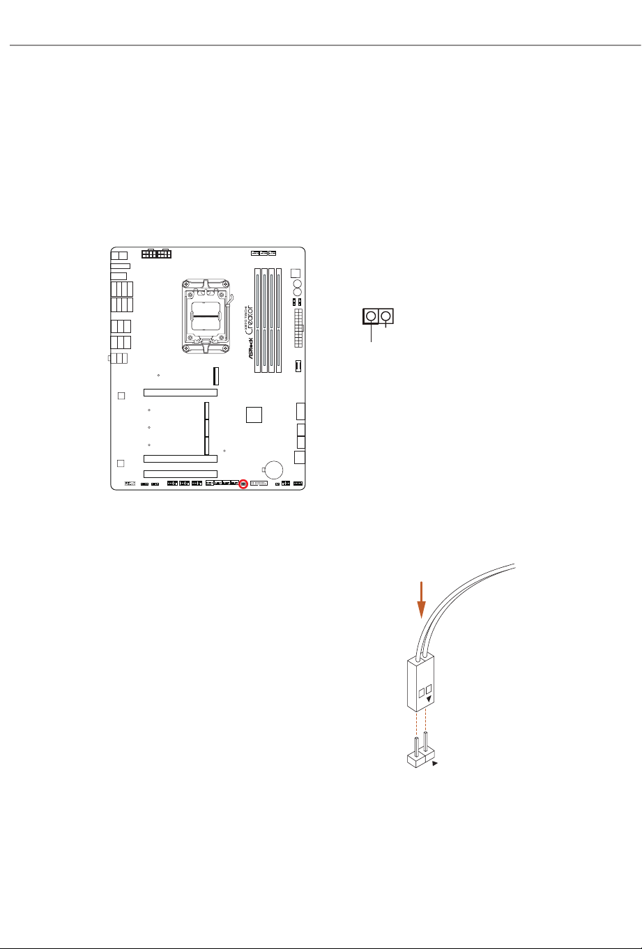
ermistor Cable Header
(2-pin T_SENSOR1) (see p.7, No. 22)
e ermistor Cable Header is used to connect thermistor cable to monitor the
temperature of the critical components. Plug the thermistor cable that come with the
package to these headers, and then attach the sensor ends to the components to detect
their temperature.
Connect your
ermistor Cable
to the
ermistor Cable Header
(
T_SENSOR1)
on the motherboard.
T
_SENSOR
T_SENSOR1
SENSOR IN
GND
1
51
X870 Taichi Creator
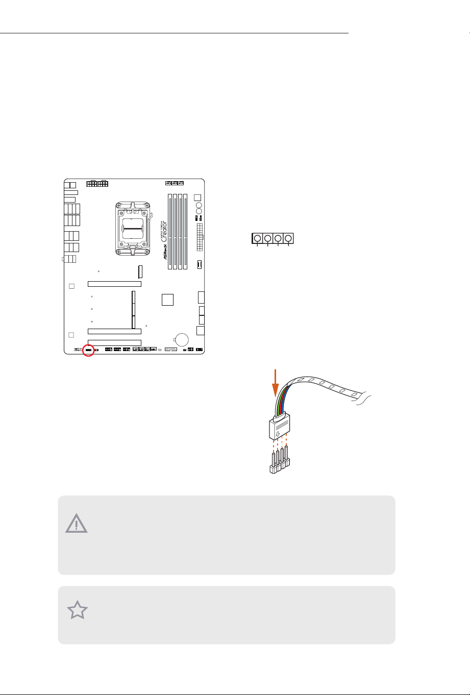
RGB LED Header
(4-pin RGB_LED1) (see p.7, No. 31)
is RGB header is used to connect RGB LED extension cable which allow users to choose
from various LED lighting eects.
Caution: Never install the RGB LED cable in the wrong orientation; otherwise, the
cable may be damaged.
1. Never install the RGB LED cable in the wrong orientation; otherwise, the cable
may be damaged.
2. Before installing or removing your RGB LED cable, please power o your system
and unplug the power cord from the power supply. Failure to do so may cause dam-
ages to motherboard components.
1. Please note that the RGB LED strips do not come with the package.
2. e RGB LED header supports standard 5050 RGB LED strip (12V/G/R/B), with a
maximum power rating of 3A (12V) and length within 2 meters.
1
2
V
G
R
B
1
RGB_LED1
+12V GRB
1
Connect your RGB LED strip to the
RGB LED
Header
(
RGB_LED1)
on the motherboard.
52
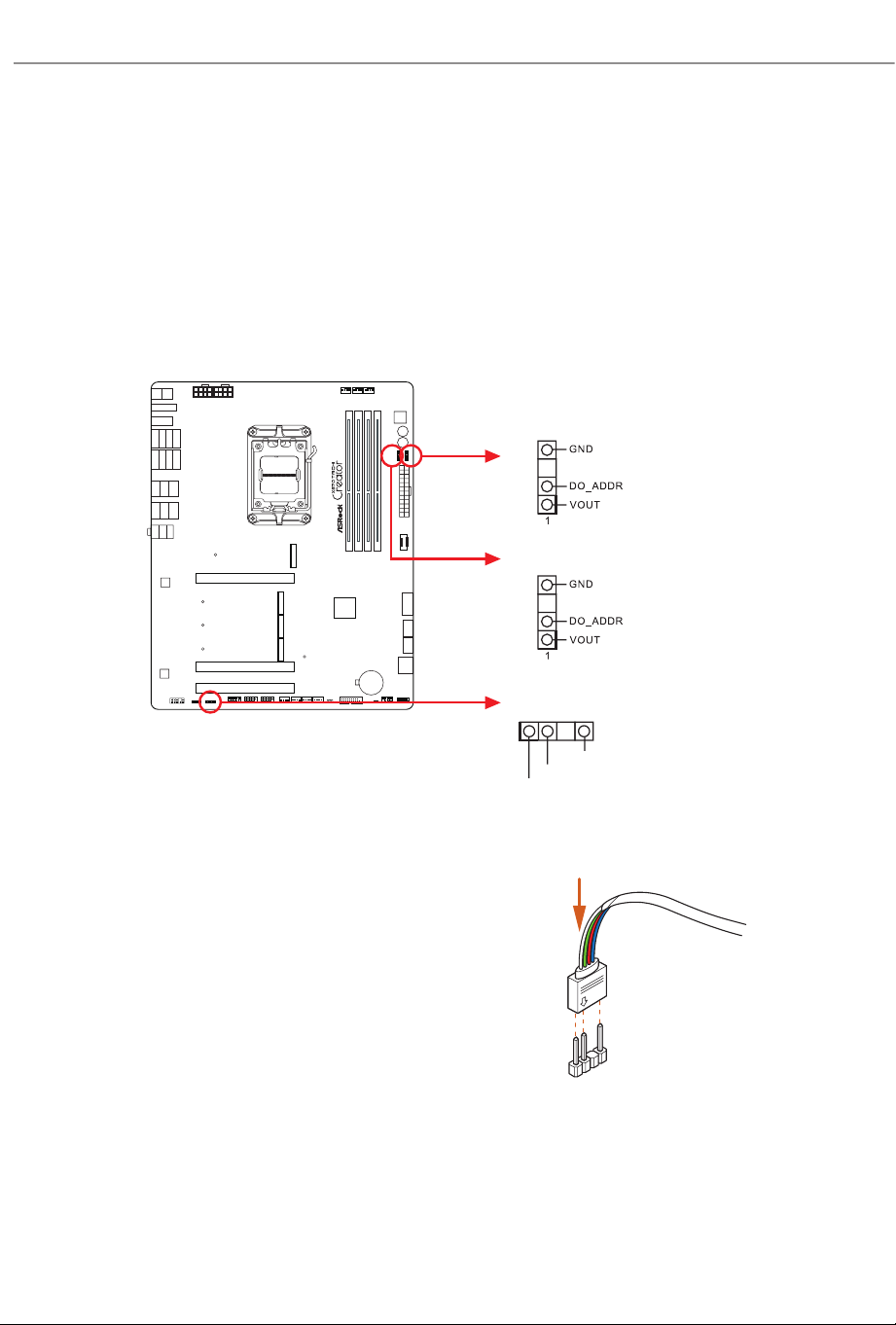
Addressable LED Headers
(3-pin ADDR_LED1) (see p.7, No. 30)
(3-pin ADDR_LED2) (see p.7, No. 11)
(3-pin ADDR_LED3) (see p.7, No. 10)
ese headers are used to connect
Addressable
LED extension cables which allow users to
choose from various LED lighting eects.
Caution: Never install the Addressable LED cable in the wrong orientation; otherwise,
the cable may be damaged.
1
Connect your
Addressable RGB LED
strips
to the
Addressable LED Headers (ADDR_
LED1 / ADDR_LED2 / ADDR_LED3)
on
the motherboard.
VOUT
DO_ADDR
GN
D
1
ADDR_LED1
ADDR_LED3
ADDR_LED2
53
X870 Taichi Creator
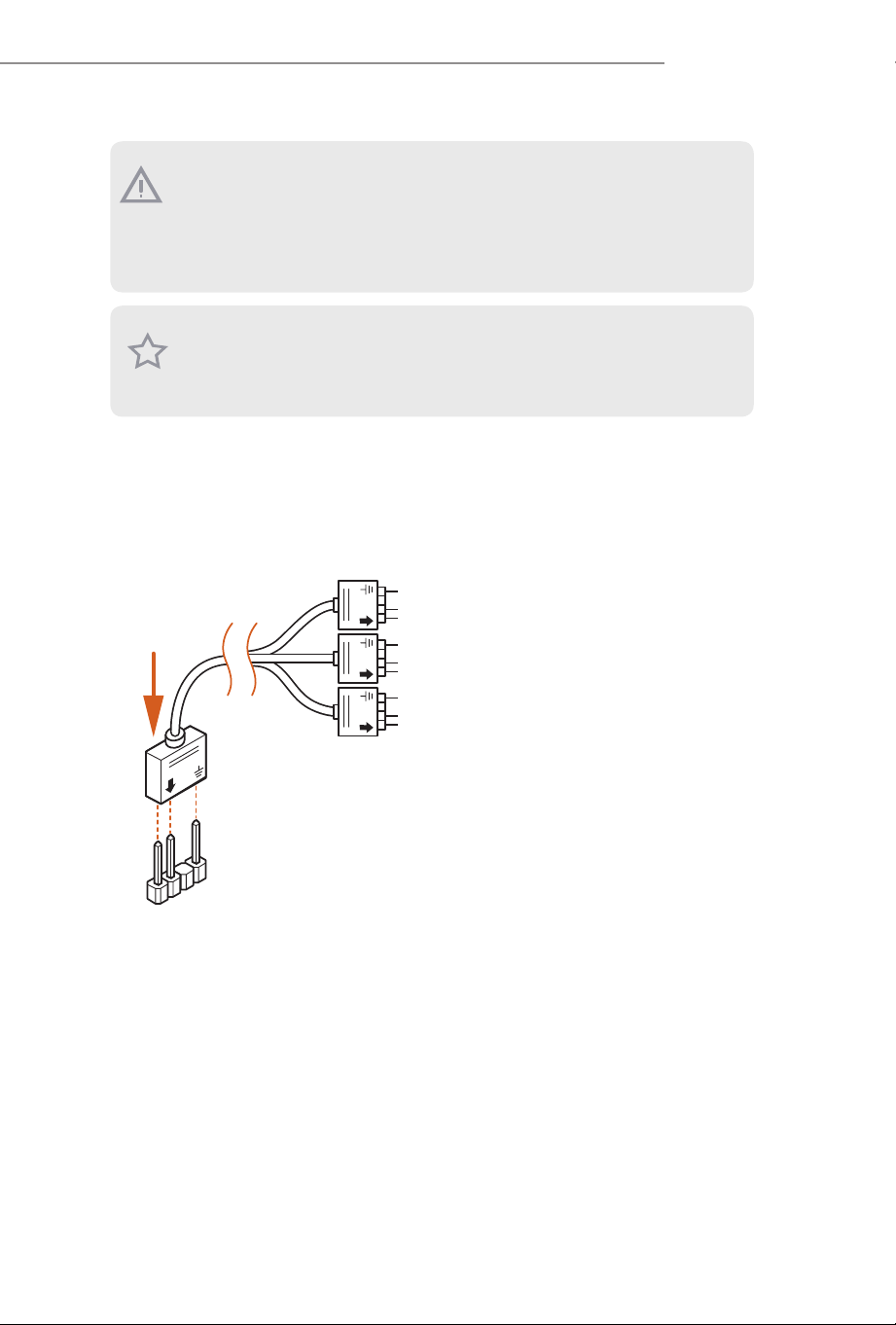
1. Never install the Addressable LED cable in the wrong orientation; otherwise, the cable
may be damaged.
2. Before installing or removing your Addressable LED cable, please power o your system
and unplug the power cord from the power supply. Failure to do so may cause damages to
motherboard components.
1. Please note that the Addressable LED strips do not come with the package.
2. e Addressable LED header supports WS2812B addressable RGB LED strip (5V/
Data/GND), with a maximum power rating of 3A (5V) and length within 2 meters.
e ARGB Splitter Cable that comes with the package allows you to extend and connect
various addressable RGB LED strips or devices through a single 3-pin Addressable
LED Header on the motherboard.
1
D
DDD
54
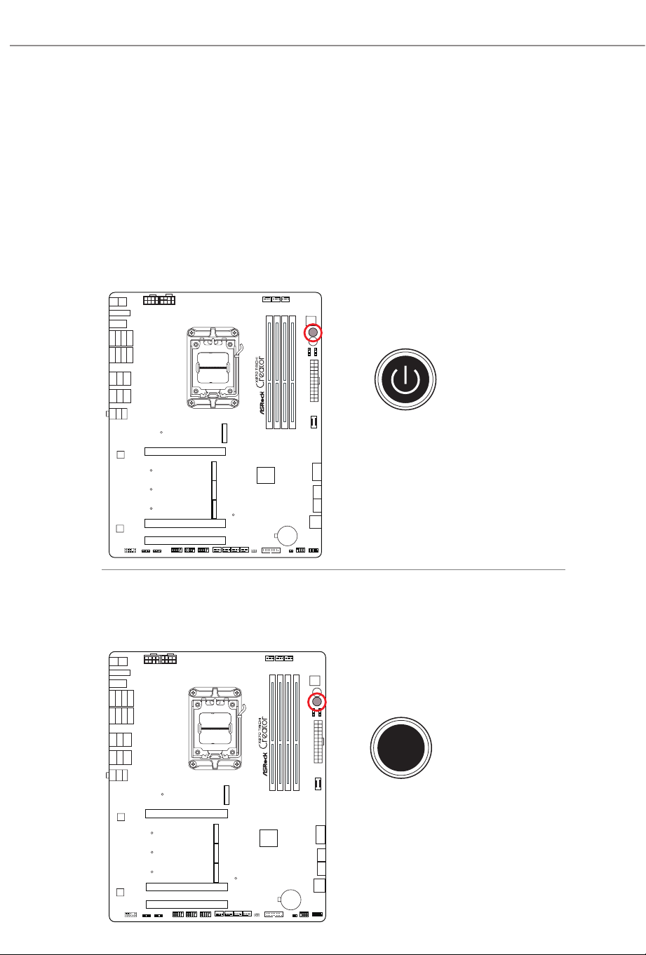
2.13 Smart Buttons
e motherboard has four smart switches: Power Button, Reset Button, Clear
CMOS Buttons and BIOS Flashback Button, allowing users to quickly turn on/o
the system, reset the system, clear the CMOS values or ash the BIOS.
Power Button
(PWRBTN1) (see p.7, No. 8)
Power Button allows users to quickly turn on/o the system.
Reset Button
(RSTBTN1) (see p.7, No. 9)
Reset Button allows users to quickly reset the system.
RSTBTN1
PWRBTN1
Reset
55
X870 Taichi Creator
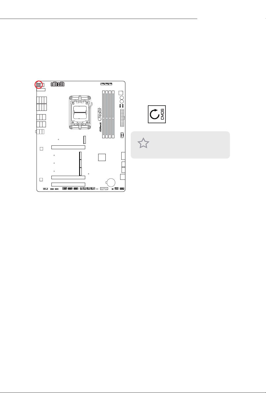
Clear CMOS Button
(CLRCMOS) (see p.9, No. 16)
Clear CMOS Button allows users to quickly clear the CMOS values.
CLRCMOS
is function is workable only when
you power o your computer and
unplug the power supply.
56
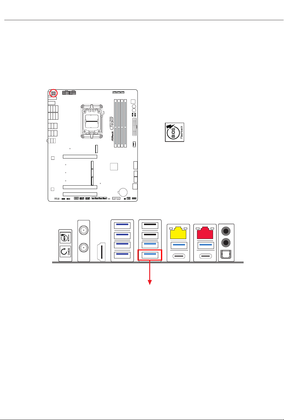
BIOS Flashback Button
(BIOS_FB) (see p.9, No. 1)
BIOS Flashback Button allows users to ash the BIOS.
BIOS_FB
USB BIOS Flashback port

57
X870 Taichi Creator
ASRock BIOS Flashback feature allows you to update BIOS without powering on the
system, even without CPU.
To use the USB BIOS Flashback function, Please follow the steps below.
1. Download the latest BIOS le from ASRock's website : http://www.asrock.com.
2. Copy the BIOS le to your USB ash drive. Please make sure the le system of
your USB ash drive must be FAT32.
3. Extract BIOS le from the zip le.
4. Rename the le to “creative.rom” and save it to the root directory of X: USB
ash drive.
5. Plug the 24-pin power connector to the motherboard. en turn on the power
supply's AC switch.
*ere is no need to power on the system.
6. en plug your USB drive to the USB BIOS Flashback port.
7. Press the BIOS Flashback Switch for about three seconds. en the LED starts
to blink.
8. Wait until the LED stops blinking, indicating that BIOS ashing has been
completed.
*If the LED light turns solid green, this means that the BIOS Flashback is not
operating properly. Please make sure that you plug the USB drive to the USB
BIOS Flashback port.
**If the LED does not light up at all
,
then please disconnect power from the
system and remove/disconnect the CMOS battery from the motherboard for
several minutes. Reconnect power and battery and try again.
Before using the BIOS Flashback function, please suspend BitLocker and any encryption
or security relying on the TPM. Make sure that you have already stored and backup-ed
the recovery key. If the recovery key is missing while encryption is active, the data will stay
encrypted and the system will not boot into the operating system. It is recommended to dis-
able fTPM before updating the BIOS. Otherwise an unpredictable failure may occur.
58
2.14 Dr. Debug
Dr. Debug is used to provide code information, which makes troubleshooting even
easier. Please see the diagrams below for reading the Dr. Debug codes.
Code Description
0x10 PEI_CORE_STARTED
0x11 PEI_CAR_CPU_INIT
0x15 PEI_CAR_NB_INIT
0x19 PEI_CAR_SB_INIT
0x31 PEI_MEMORY_INSTALLED
0x32 PEI_CPU_INIT
0x33 PEI_CPU_CACHE_INIT
0x34 PEI_CPU_AP_INIT
0x35 PEI_CPU_BSP_SELECT
0x36 PEI_CPU_SMM_INIT
0x37 PEI_MEM_NB_INIT
0x3B PEI_MEM_SB_INIT
0x4F PEI_DXE_IPL_STARTED
0x60 DXE_CORE_STARTED
0x61 DXE_NVRAM_INIT
0x62 DXE_SBRUN_INIT

59
X870 Taichi Creator
0x63 DXE_CPU_INIT
0x68 DXE_NB_HB_INIT
0x69 DXE_NB_INIT
0x6A DXE_NB_SMM_INIT
0x70 DXE_SB_INIT
0x71 DXE_SB_SMM_INIT
0x72 DXE_SB_DEVICES_INIT
0x78 DXE_ACPI_INIT
0x79 DXE _CSM_INIT
0x90 DXE_BDS_STARTED
0x91 DXE_BDS_CONNECT_DRIVERS
0x92 DXE_PCI_BUS_BEGIN
0x93 DXE_PCI_BUS_HPC_INIT
0x94 DXE_PCI_BUS_ENUM
0x95 DXE_PCI_BUS_REQUEST_RESOURCES
0x96 DXE_PCI_BUS_ASSIGN_RESOURCES
0x97 DXE_CON_OUT_CONNECT
0x98 DXE_CON_IN_CONNECT

60
0x99 DXE_SIO_INIT
0x9A DXE_USB_BEGIN
0x9B DXE_USB_RESET
0x9C DXE_USB_DETECT
0x9D DXE_USB_ENABLE
0xA0 DXE_IDE_BEGIN
0xA1 DXE_IDE_RESET
0xA2 DXE_IDE_DETECT
0xA3 DXE_IDE_ENABLE
0xA4 DXE_SCSI_BEGIN
0xA5 DXE_SCSI_RESET
0xA6 DXE_SCSI_DETECT
0xA7 DXE_SCSI_ENABLE
0xA8 DXE_SETUP_VERIFYING_PASSWORD
0xA9 DXE_SETUP_START
0xAB DXE_SETUP_INPUT_WAIT
0xAD DXE_READY_TO_BOOT
0xAE DXE_LEGACY_BOOT
61
X870 Taichi Creator
0xAF DXE_EXIT_BOOT_SERVICES
0xB0 RT_SET_VIRTUAL_ADDRESS_MAP_BEGIN
0xB1 RT_SET_VIRTUAL_ADDRESS_MAP_END
0xB2 DXE_LEGACY_OPROM_INIT
0xB3 DXE_RESET_SYSTEM
0xB4 DXE_USB_HOTPLUG
0xB5 DXE_PCI_BUS_HOTPLUG
0xB6 DXE_NVRAM_CLEANUP
0xB7 DXE_CONFIGURATION_RESET
0xF0 PEI_RECOVERY_AUTO
0xF1 PEI_RECOVERY_USER
0xF2 PEI_RECOVERY_STARTED
0xF3 PEI_RECOVERY_CAPSULE_FOUND
0xF4 PEI_RECOVERY_CAPSULE_LOADED
0xE0 PEI_S3_STARTED
0xE1 PEI_S3_BOOT_SCRIPT
0xE2 PEI_S3_VIDEO_REPOST

62
0xE3 PE I _ S3 _OS_WAK E
0x50 PEI_MEMORY_INVALID_TYPE
0x53 PEI_MEMORY_NOT_DETECTED
0x55 PEI_MEMORY_NOT_INSTALLED
0x57 PEI_CPU_MISMATCH
0x58 PEI_CPU_SELF_TEST_FAILED
0x59 PEI_CPU_NO_MICROCODE
0x5A PEI_CPU_ERROR
0x5B PEI_RESET_NOT_AVAILABLE
0xD0 DXE_CPU_ERROR
0xD1 DXE_NB_ERROR
0xD2 DXE_SB_ERROR
0xD3 DXE_ARCH_PROTOCOL_NOT_AVAILABLE
0xD4 DXE_PCI_BUS_OUT_OF_RESOURCES
0xD5 DXE_LEGACY_OPROM_NO_SPACE
0xD6 DXE_NO_CON_OUT
0xD7 DXE_NO_CON_IN
63
X870 Taichi Creator
0xD8 DXE_INVALID_PASSWORD
0xD9 DXE_BOOT_OPTION_LOAD_ERROR
0xDA DXE_BOOT_OPTION_FAILED
0xDB DXE_FLASH_UPDATE_FAILED
0xDC DXE_RESET_NOT_AVAILABLE
0xE8 PEI_MEMORY_S3_RESUME_FAILED
0xE9 PEI_S3_RESUME_PPI_NOT_FOUND
0xEA PEI_S3_BOOT_SCRIPT_ERROR
0xEB PEI_S3_OS_WAKE_ERROR
64
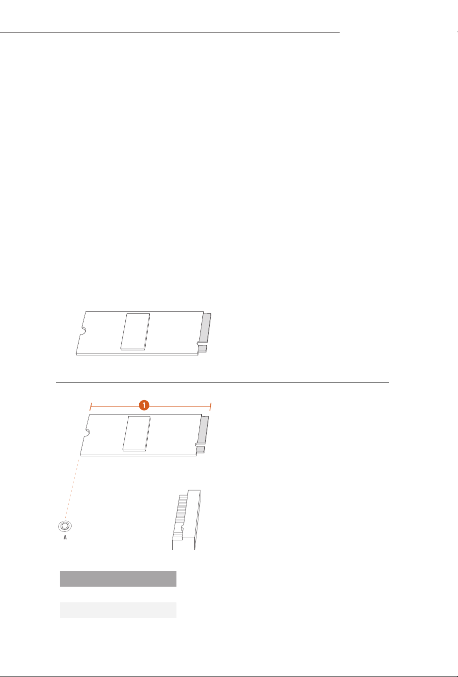
2.15 M.2 SSD Installation Guide (M2_1)
e M.2 is a small size and versatile card edge connector that aims to replace mPCIe and
mSATA. e
Blazing M.2 Socket (M2_1, Key M), supports type 2280 PCIe Gen5x4 (128
Gb/s) mode.
* M2_1 is the rst priority for M.2 installation.
* M2_1 will run at Gen5x4 with 9000 and 7000 series processors and Gen4x4 with 8000
(Phoenix 1 and Phoenix 2) series processors.
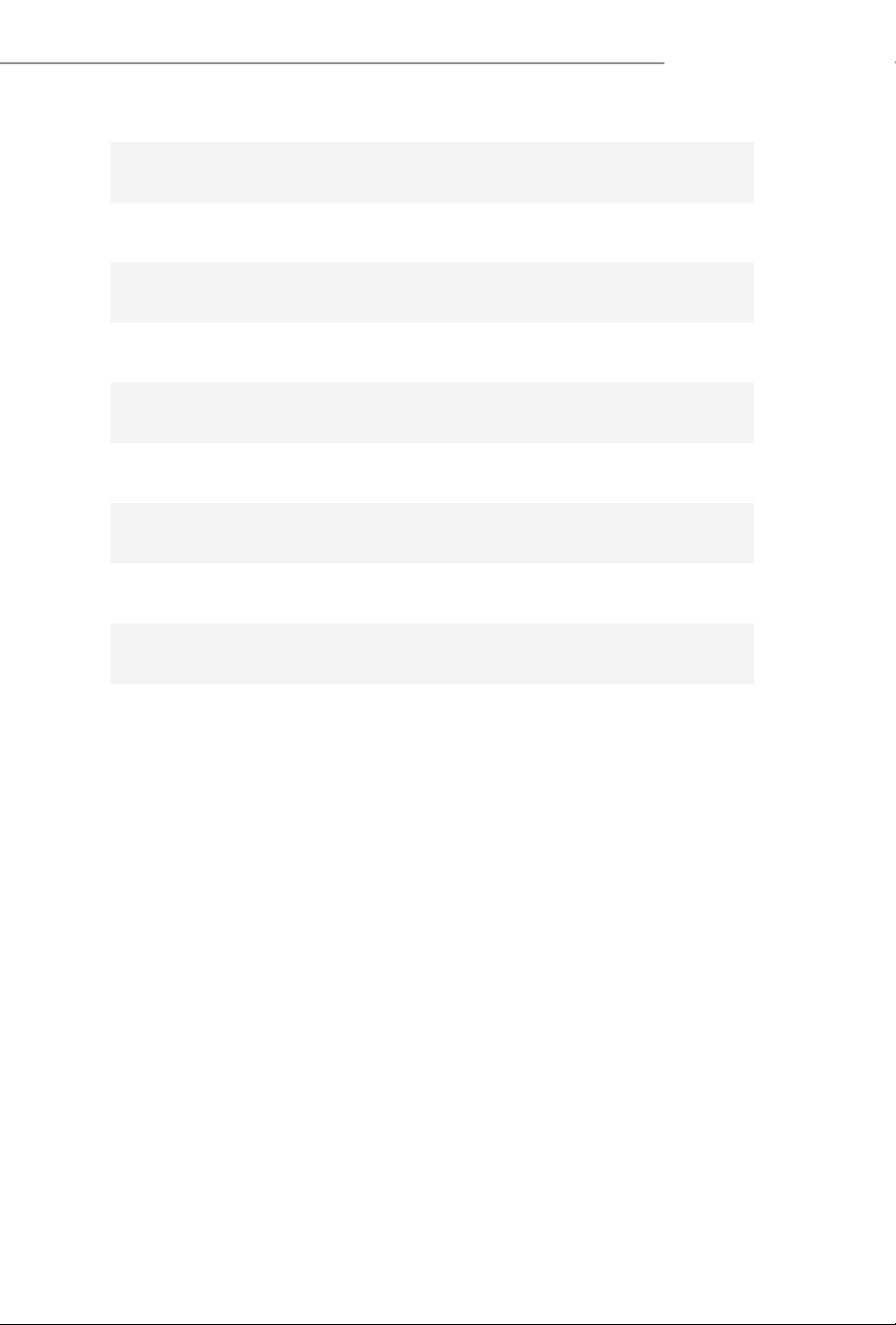
Installing the M.2 SSD
Step 1
Prepare a M.2 SSD.
Step 2
Depending on the PCB type and
length of your M.2 SSD, nd the
corresponding nut location to be
used.
No. 1
Nut Location A
PCB Length 8cm
Module Type Type2280
65
X870 Taichi Creator
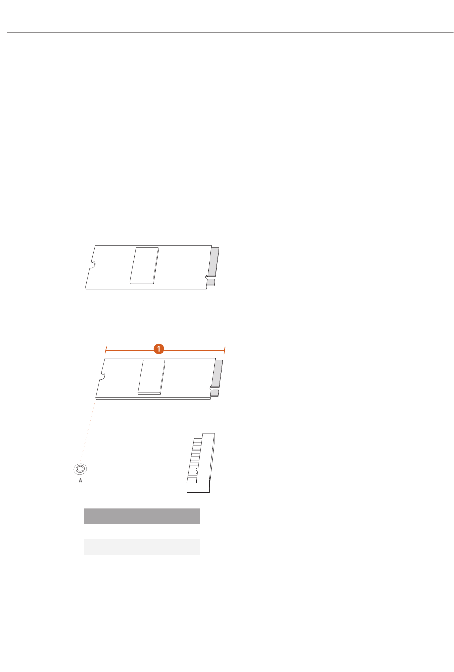
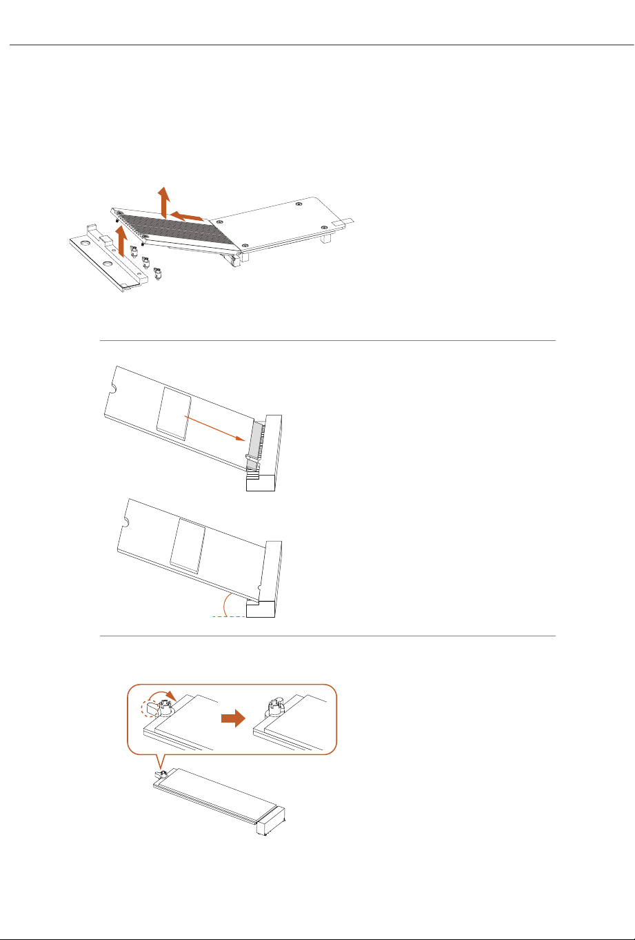
Step 3
Push the button on the M.2 heatsink
in the direction shown (A). en li
up the heatsink (B) and move it in
the direction shown (C).
*Please remove the protective lms
on the bottom side of the M.2
heatsink before you install a M.2
SSD.
20
o
Step 4
Align and gently insert the M.2 SSD
into the M.2 slot. Please be aware
that the M.2 SSD only ts in one
orientation.
Step 5
Ensure that the notch at the end of
the M.2 SSD aligns with the nut.
en secure the M.2 SSD by turning
the nut lock clockwise to its locked
position.
C
A
B
66
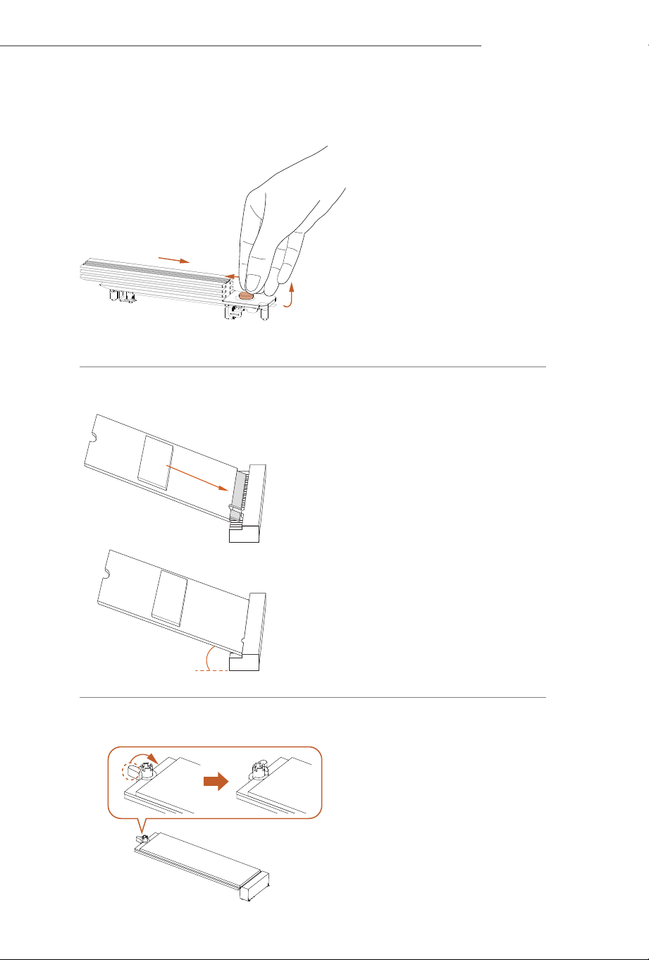
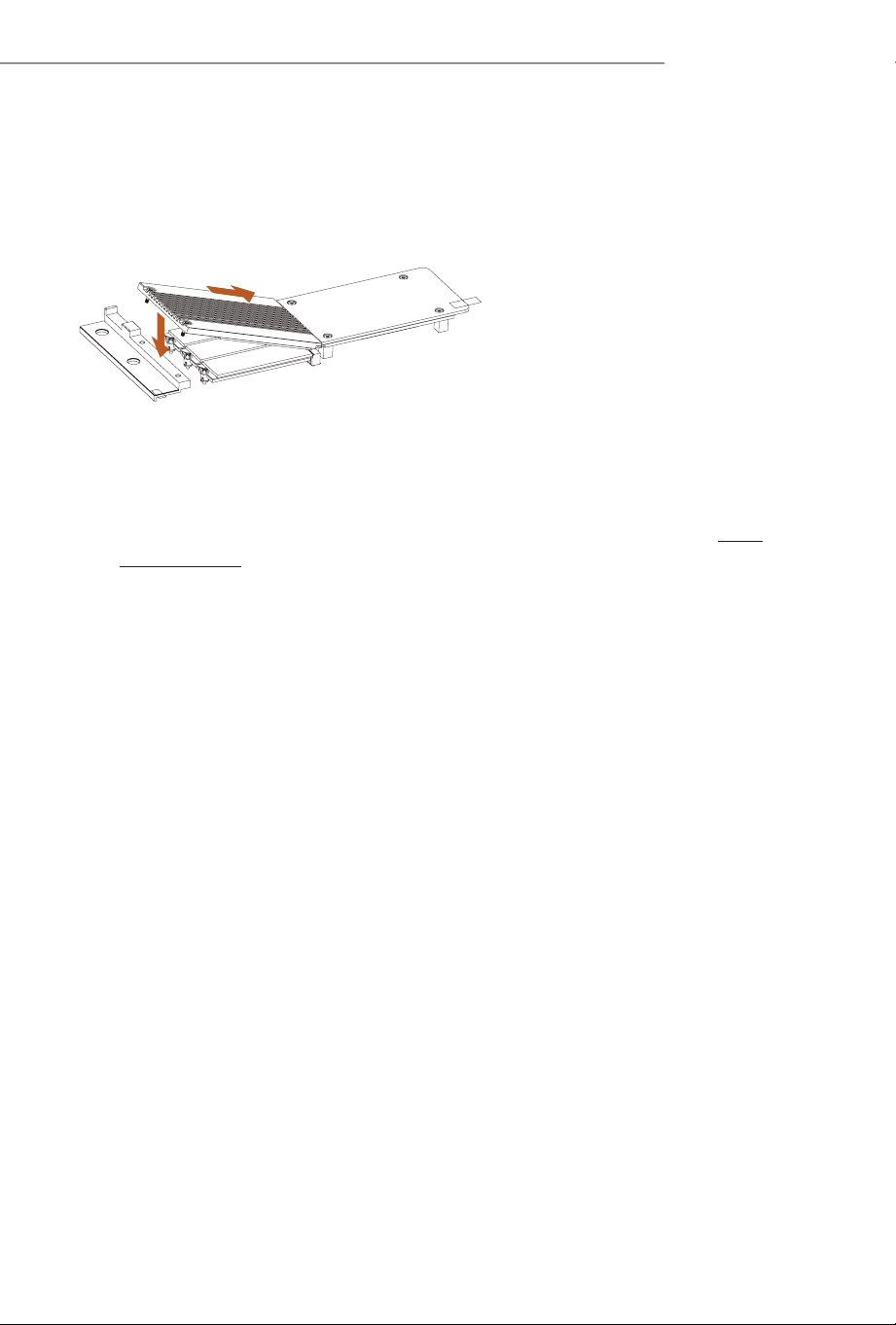
Step 6
Hook the tab of the M.2 heatsink back
onto the stando.
Step 7
Press the M.2 heatsink down into
place.
*Be sure not to press down the button
on the M.2 heatsink.
Step 8
Complete.
For the latest updates of M.2 SSD support list, please visit our website for details: http://
www.asrock.com
67
X870 Taichi Creator
2.16 M.2 SSD Installation Guide (M2_2/M2_3/M2_4)
e M.2 is a small size and versatile card edge connector that aims to replace mPCIe and
mSATA. e Blazing M.2 Socket (M2_2, Key M) supports type 2280 PCIe Gen5x4 (128 Gb/s)
mode. e Hyper M.2 Socket (M2_3, Key M) supports type 2280 PCIe Gen4x4 (64 Gb/
s) mode. e Ultra M.2 Socket (M2_4, Key M) supports type 2280 PCIe Gen3x4 (32 Gb/s)
mode.
* M2_2 will run at Gen5x4 with 9000 and 7000 series processors and Gen4x4 with 8000
(Phoenix 1) series processors. M2_2 will be unavailable with 8000 (Phoenix 2) series
processors.
* If M2_2 is occupied, both rear USB4 Type-C Ports and M2_2 will downgrade to x2
mode. You can switch M2_2 to x4 mode in BIOS setting, but doing so will disable USB4_
TC1 and USB4_TC2.
* If M2_4 is occupied, both PCIE3 and M2_4 will downgrade to x2 mode.
Installing the M.2 SSD
Step 1
Prepare a M.2 SSD.
Step 2
Depending on the PCB type and
length of your M.2 SSD, nd the
corresponding nut location to be
used.
No. 1
Nut Location A
PCB Length 8cm
Module Type Type2280
68
Step 3
Before installing a M.2 SSD, please
loosen the screws and move the M.2
heatsink in the direction shown
shown (A) and (B) and then li it up
(C).
*Please remove the protective lms
on the bottom side of the M.2
heatsink before you install a M.2
SSD.
20
o
Step 4
Align and gently insert the M.2 SSD
into the M.2 slot. Please be aware
that the M.2 SSD only ts in one
orientation.
Step 5
Ensure that the notch at the end of
the M.2 SSD aligns with the nut.
en secure the M.2 SSD by turning
the nut lock clockwise to its locked
position.
A
B
C
69
X870 Taichi Creator
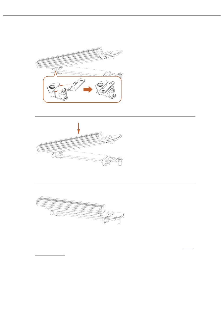
Step 6
Align and gently insert the M.2
heatsink into the slot of the adjacent
heatsink (A) and press it down
(B). en tighten the screws with
a screwdriver to secure the M.2
heatsink into place. Please do not
overtighten the screws as this might
damage the M.2 heatsink.
For the latest updates of M.2 SSD support list, please visit our website for details: http://
www.asrock.com
A
B

Version 1.0
Published July 2025
Copyright©2025 ASRock INC. All rights reserved.
Copyright Notice
No part of this documentation may be reproduced, transcribed, transmitted, or
translated in any language, in any form or by any means, except duplication of
documentation by the purchaser for backup purpose, without written consent of
ASRock Inc.
Products and corporate names appearing in this documentation may or may not
be registered trademarks or copyrights of their respective companies, and are used
only for identication or explanation and to the owners’ benet, without intent to
infringe.
Disclaimer
Specications and information contained in this documentation are furnished for
informational use only and subject to change without notice, and should not be
constructed as a commitment by ASRock. ASRock assumes no responsibility for
any errors or omissions that may appear in this documentation.
To the extent permitted by law, with respect to the contents of this documentation,
ASRock does not provide warranty of any kind, either expressed or implied,
including but not limited to the implied warranties or conditions of merchantability
or tness for a particular purpose. In no event shall ASRock, its directors, ocers,
employees, or agents be liable for any indirect, special, incidental, or consequential
damages (including damages for loss of prots, loss of business, loss of data,
interruption of business and the like), even if ASRock has been advised of the
possibility of such damages arising from any defect or error in the documentation
or product.
FCC Compliance Statement
is device complies with Part 15 of the FCC Rules. Operation is subject to the following
two conditions:
(1) this device may not cause harmful interference, and
(2) this device must accept any interference received, including interference that may
cause undesired operation.
is equipment has been tested and found to comply with the limits for a Class B digital
device, pursuant to part 15 of the FCC Rules. ese limits are designed to provide
reasonable protection against harmful interference in a residential installation. is
equipment generates, uses and can radiate radio frequency energy and, if not installed
and used in accordance with the instructions, may cause harmful interference to radio
communications. However, there is no guarantee that interference will not occur in a
particular installation. If this equipment does cause harmful interference to radio or
television reception, which can be determined by turning the equipment o and on,
the user is encouraged to try to correct the interference by one or more of the following
measures:
- Reorient or relocate the receiving antenna.
- Increase the separation between the equipment and receiver.
- Connect the equipment into an outlet on a circuit dierent from that to which the
receiver is connected.
- Consult the dealer or an experienced radio/TV technician for help.
Button Battery Safety Notice
- Remove and immediately recycle or dispose of used batteries according to local
regulations and keep away from children. Do NOT dispose of batteries in household
trash or incinerate.
- Even used batteries may cause severe injury or death.
- Call a local poison control center for treatment information.
- Battery type: CR2032
- Battery voltage: 3V
- Non-rechargeable batteries are not to be recharged.
- Do not force discharge, recharge, disassemble, heat above (manufacturer's specied
temperature rating) or incinerate. Doing so may result in injury due to venting, leakage
or explosion resulting in chemical burns.
- is product contains an irreplaceable battery.
- is icon indicates that a swallowed button battery can cause serious injury or death.
Please keep batteries out of sight or reach of children.
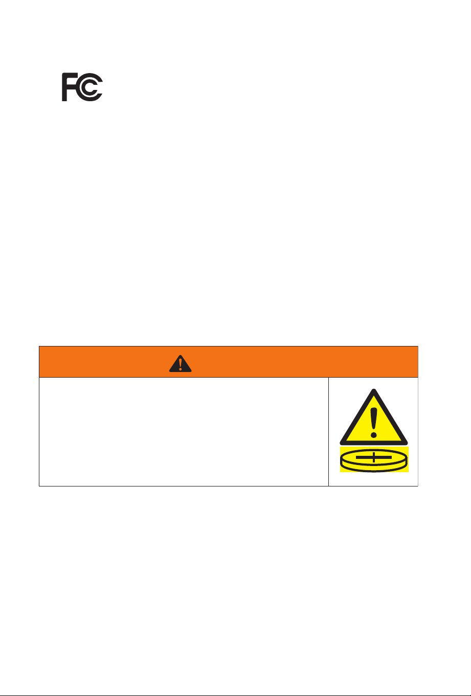
WARNING
• INGESTION HAZARD: This product contains a button cell or
coin battery.
• DEATH or serious injury can occur if ingested.
• A swallowed button cell or coin battery can cause Internal
Chemical Burns in as little as 2 hours.
• KEEP new and used batteries OUT OF REACH of CHILDREN
• Seek immediate medical attention if a battery is suspected to
be swallowed or inserted inside any part of the body.
CALIFORNIA, USA ONLY
e Lithium battery adopted on this motherboard contains Perchlorate, a toxic substance
controlled in Perchlorate Best Management Practices (BMP) regulations passed by the
California Legislature. When you discard the Lithium battery in California, USA, please
follow the related regulations in advance.
“Perchlorate Material-special handling may apply, see www.dtsc.ca.gov/hazardouswaste/
perchlorate”
CALIFORNIA, USA ONLY
WARNING:
Risk of cancer and reproductive harm from exposure to Lead.
See www.P65Warnings.ca.gov
CE Conformity
ASRock INC. hereby declares that this device is in compliance with the essential require-
ments and other relevant provisions of related Directives. Full text of EU declaration of
conformity is available at: http://www.asrock.com
ASRock follows the green design concept to design and manufacture our products, and
makes sure that each stage of the product life cycle of ASRock product is in line with
global environmental regulations. In addition, ASRock disclose the relevant information
based on regulation requirements.
Please refer to https://www.asrock.com/general/about.asp?cat=Responsibility for infor-
mation disclosure based on regulation requirements ASRock is complied with.
UKCA Conformity
ASRock INC. hereby declares that this device is in compliance with the essential require-
ments and other relevant provisions of related UKCA Directives. Full text of UKCA
declaration of conformity is available at: http://www.asrock.com
Consumer Limited Warranty - Australia
Our goods come with guarantees that cannot be excluded under the Australian Consum-
er Law. You are entitled to a replacement or refund for a major failure and compensation
for any other reasonably foreseeable loss or damage caused by our goods. You are also
entitled to have the goods repaired or replaced if the goods fail to be of acceptable quality
and the failure does not amount to a major failure. If you require assistance please call
ASRock Tel : +886-2-28965588 ext.123 (Standard International call charges apply)
WARNING
THIS PRODUCT CONTAINS A BUTTON BATTERY
If swallowed, a button battery can cause serious injury or death.
Please keep batteries out of sight or reach of children.
Proper Disposal
DO NOT throw the motherboard in municipal waste. is product has
been designed to enable proper reuse of parts and recycling. is symbol
of the crossed out wheeled bin indicates that the product (electrical and
electronic equipment) should not be placed in municipal waste. Check lo-
cal regulations for disposal of electronic products.
Class B ITE
この装置は、クラスB情報技術装置です。この装置は、家庭環境で使用することを目的
としていますが、この装置がラジオやテレビジョン受信機に近 接して使用されると、受
信障害を引き起こすことがあります。取扱説明書に従って正しい取り扱いをして下さ
い。
Trademark Information
e terms HDMI® and HDMI High-Denition Multimedia Interface, and the HDMI
logo are trademarks or registered trademarks of HDMI Licensing LLC in the United
States and other countries.
European Community Radio Equipment Directive Compliance
Statement
is device complies with directive 2014/53/EU issued by the Commision of the
European Community. is equipment complies with EU radiation exposure
limits set forth for an uncontrolled environment.
is equipment should be installed and operated with minimum distance 20cm
between the radiator & your body.
Operations in the 5.15-5.35/6GHz band are restricted to indoor usage only.
Radio Frequency Bands and Maximum Power Levels
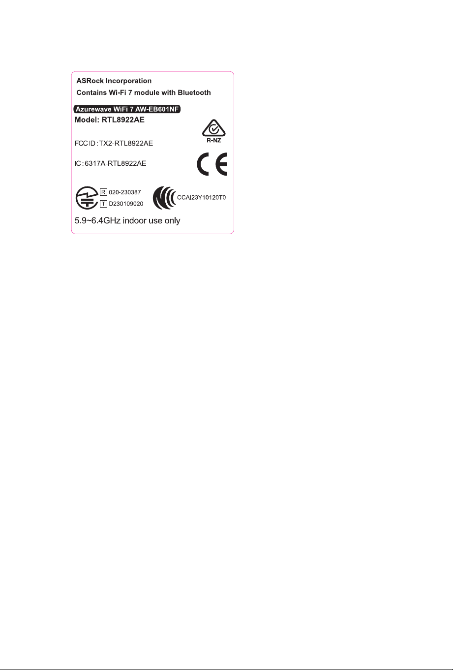
• Features : Wi-Fi 6E, BT, Wi-Fi 7
• Frequency Range : 2.4 GHz: 2400-2485MHz; 5 GHz: 5150-5350MHz, 5470-5725MHz,
5725-5850MHz; 6 GHz: 5955-6415MHz
• Max Power Level : 2.4 GHz: 20dBm; 5 GHz: 23dBm; 6 GHz: 23dBm
Compliance Statement of Innovation, Science and Economic
Development Canada (ISED)
is device complies with with Innovation, Science and Economic Development
Canada’s licence-exempt RSS(s). Operation is subject to the following two condi-
tions: (1) this device may not cause interference, and (2) this device must accept
any interference, including interference that may cause undesired operation of the
device. Operation in the band 5150-5250 MHz is only for indoor use to reduce the
potential for harmful interference to co-channel mobile satellite systems. CAN
ICES-003(B)/NMB-003(B)
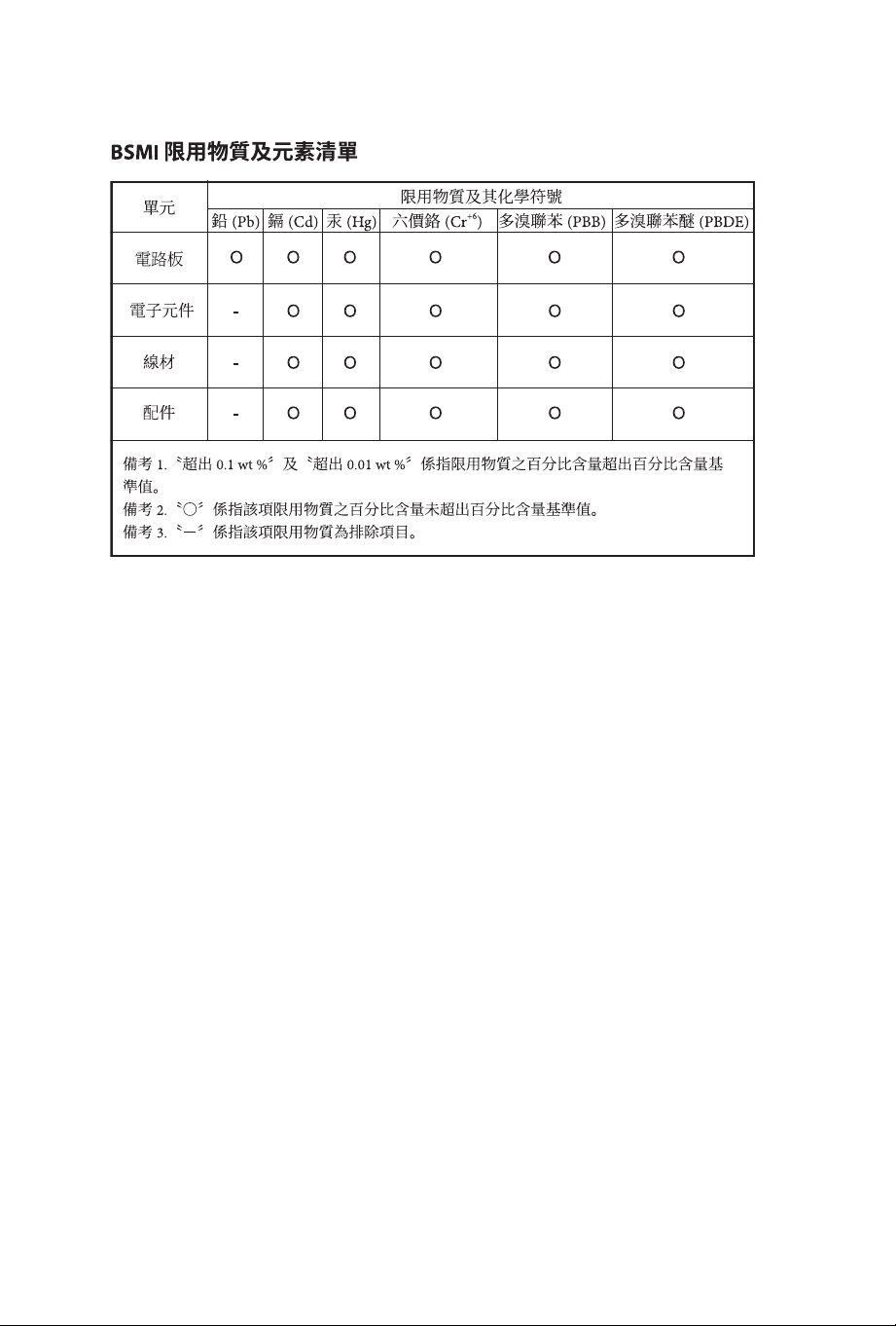
NCC
無線設備警告聲明
經型式認證合格之低功率射頻電機,非經許可,公司、商號或使用者均不得擅自變更頻
率、
加大功率或變更原設計之特性及功能。
低功率射頻電機之使用不得影響飛航安
全及干擾合法通信;經發現有干擾現象時,應立即停用,並改善至無干擾時方得繼續使
用。前項合法通信,指依電信法規定作業之無線電通信。低功率射頻電機須忍受合法
通信或工業、科學及醫療用電波輻射性電機設備之干擾。
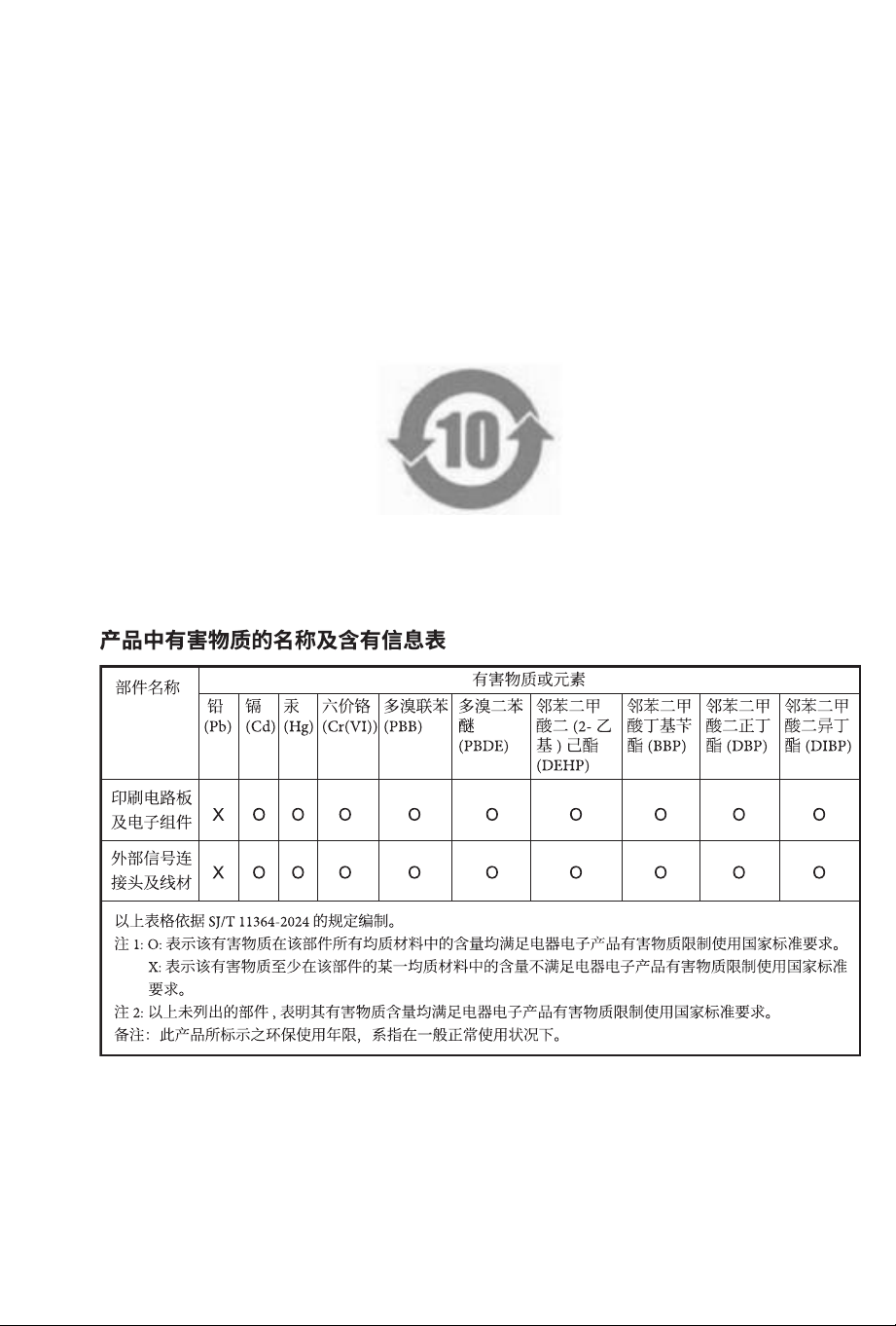
China RoHS
电子信息产品污染控制标示
依据中国发布的「电子电气产品中限用物质的限量要求」及
SJ/T 11364-2024
《电器电
子产品有害物质限制使用标识要求》,电子信息产品应进行标示,藉以向消费者揭露
产品中含有
的有毒有害物质或元素不致发生外泄或突变从而对环境造成污染或对人
身、财产造成
严重损害的期限。依上述规定,您可于本产品之印刷电路板上看见图一
之标示。图一
中之数字为产品之环保使用期限。由此可知此主板之环保使用期限为
10
年。
图一