Contact Information
If you need to contact ASRock or want to know more about ASRock, you’re welcome
to visit ASRock’s website at http://www.asrock.com; or you may contact your dealer
for further information. For technical questions, please submit a support request
form at https://event.asrock.com/tsd.asp
ASRock Incorporation
e-mail: [email protected]
ASRock EUROPE B.V.
e-mail: sales@asrock.nl
ASRock America, Inc.
e-mail: sales@asrockamerica.com
Scan the QR code to view more manuals and documents.

Contents
Chapter 1 Introduction 1
1.1 Package Contents 1
1.2 Speciications 2
1.3 Motherboard Layout 7
1.4 I/O Panel 9
1.5 Block Diagram 11
1.6 802.11axe Wi-Fi 6E Module and ASRock WiFi 2.4/5/6 GHz
Antennas 12
Chapter 2 Installation 14
2.1 Installing the CPU 16
2.2 Installing the CPU Fan and Heatsink 18
2.3 Installing Memory Modules (DIMM)
19
2.4 Connecting the Front Panel Header 21
2.5 Installing the Motherboard 22
2.6 Installing SATA Drives 23
2.7 Installing a Graphics Card 25
2.8 Connecting Peripheral Devices 27
2.9 Connecting the Power Connectors 28
2.10 Power On 29
2.11 Jumpers Setup 30
2.12 Onboard Headers and Connectors 31
2.13 Post Status Checker 47


English
1
Z890 Steel Legend WiFi
Chapter 1 Introduction
hank you for purchasing ASRock Z890 Steel Legend WiFi motherboard, a reliable
motherboard produced under ASRock’s consistently stringent quality control.
It delivers excellent performance with robust design conforming to ASRock’s
commitment to quality and endurance.
1.1 Package Contents
•
ASRock Z890 Steel Legend WiFi Motherboard (ATX Form Factor)
•
2 x Serial ATA (SATA) Data Cables (Optional)
•
2 x ASRock WiFi 2.4/5/6 GHz Antennas (Optional)
•
1 x hermistor Cable (Optional)
Because the motherboard speciications and the BIOS sotware might be updated, the
content of this documentation will be subject to change without notice. In case any modi-
ications of this documentation occur, the updated version will be available on ASRock’s
website without further notice. If you require technical support related to this mother-
board, please visit our website for speciic information about the model you are using. You
may ind the latest VGA cards and CPU support list on ASRock’s website as well. ASRock
website http://www.asrock.com.

English
2
1.2 Speciications
Platform
•
ATX Form Factor
•
2oz Copper PCB
CPU
•
Supports Intel® Core™ Ultra Processors (Series 2)
(LGA1851RL-ILM)
•
Supports Intel® Hybrid Technology
•
Supports Intel® Turbo Boost Max 3.0 Technology
•
Supports Intel® hermal Velocity Boost (TVB)
•
Supports Intel® Adaptive Boost Technology (ABT)
•
Integrated NPU for dedicated AI acceleration
Chipset
•
Intel® Z890
Memory
•
Dual Channel DDR5 Memory Technology
•
4 x DDR5 DIMM Slots
•
Supports DDR5 non-ECC, un-bufered memory up to
9066+(OC)*
•
Max. capacity of system memory: 256GB
•
Supports Intel® Extreme Memory Proile (XMP) 3.0x
* Please refer to Memory Support List on ASRock's website for
more information. (http://www.asrock.com/)
Expansion
Slot
CPU:
•
1 x PCIe 5.0 x16 Slot (PCIE1), supports x16 mode*
Chipset:
•
1 x PCIe 4.0 x16 Slot (PCIE2), supports x4 mode*
•
1 x PCIe 4.0 x4 Slot (PCIE3), supports x4 mode*
•
1 x M.2 Socket (Key E), supports type 2230 WiFi/BT PCIe
WiFi module and Intel® CNVio/CNVio2 (Integrated WiFi/
BT)
* PCIE1 supports PCIe riser cards to extend one x16 slot to x8/
x8 or x8/x4/x4 slots.
* Supports NVMe SSD as boot disks
Graphics
•
Intel® UHD Graphics Built-in Visuals and the VGA outputs
can be supported only with processors which are GPU
integrated.

English
3
Z890 Steel Legend WiFi
•
Intel® X
e
LPG Graphics Architecture
•
1 x HDMI 2.1 TMDS/FRL 8G Compatible, supports HDR,
HDCP 2.3 and max. resolution up to 4K 120Hz
•
2 x Intel® hunderbolt
TM
4, support HDCP 2.3 and max.
resolution up to 8K 60Hz / 5K 120Hz*
* Supports two 4K displays or one 8K display
* Only the CPU’s embedded graphics can be displayed through
hunderbolt ports. If you want to display to a hunderbolt
monitor, please use CPU models with embedded graphics.
Audio
•
7.1 CH HD Audio with Content Protection (Realtek
ALC1220 Audio Codec)
•
Impedance Sensing on Rear Out port
•
Individual PCB Layers for R/L Audio Channel
•
Nahimic Audio
LAN
•
2.5 Gigabit LAN 10/100/1000/2500 Mb/s
•
Dragon RTL8125BG
•
Supports Dragon 2.5G LAN Sotware
- Smart Auto Adjust Bandwidth Control
- Visual User Friendly UI
- Visual Network Usage Statistics
- Optimized Default Setting for Game, Browser, and
Streaming Modes
- User Customized Priority Control
Wireless
LAN
•
802.11be 2x2 Wi-Fi 7 Module
•
Supports IEEE 802.11a/b/g/n/ac/ax/axe/be
•
Supports 2.4GHz/5GHz/6GHz* frequency band
•
Supports 320MHz channel bandwidth with 6GHz* frequen-
cy band
* Wi-Fi 7 (6GHz band) will be supported by Microsot® Win-
dows® 11. he availability will depend on the diferent regula-
tion status of each country and region. It will be activated (for
supported countries) through Windows Update and sotware
updates once available.
•
1 antenna to support 2 (Transmit) x 2 (Receive) diversity
technology
•
Supports Bluetooth 5.4
•
Supports MU-MIMO

English
4
USB
CPU:
•
2 x hunderbolt
TM
4 Type-C (Rear)
Chipset:
•
1 x USB 3.2 Gen2x2 Type-C (Front)
•
2 x USB 3.2 Gen2 Type-A (Rear)
•
8 x USB 3.2 Gen1 (4 Rear, 4 Front)
•
6 x USB 2.0 (2 Rear, 4 Front)
* All USB ports support ESD Protection
Rear Panel
I/O
•
2 x Antenna Ports
•
1 x HDMI Port
•
1 x Optical SPDIF Out Port
•
2 x hunderbolt
TM
4 Type-C Ports (40 Gb/s for USB4 proto-
col; 40Gb/s for hunderbolt protocol)*
•
2 x USB 3.2 Gen2 Type-A Ports (10 Gb/s)
•
4 x USB 3.2 Gen1 Ports**
•
2 x USB 2.0 Ports
•
1 x RJ-45 LAN Port
•
1 x BIOS Flashback Button
•
1 x Line Out Jack (Gold Audio Jack)
•
1 x Microphone Input Jack (Gold Audio Jack)
* Supports USB PD 3.0 up to 5V@3A (15W) charging
** USB32_34 are Lightning Gaming Ports. USB32_56 support
Ultra USB Power.
Storage
CPU:
•
1 x Blazing M.2 Socket (M2_1, Key M), supports type 2280
PCIe Gen5x4 (128 Gb/s) mode*
•
1 x Hyper M.2 Socket (M2_2, Key M), supports type 2280
PCIe Gen4x4 (64 Gb/s) mode*
Chipset:
•
1 x Hyper M.2 Socket (M2_3, Key M), supports type 2280
SATA3 6.0 Gb/s & PCIe Gen4x4 (64 Gb/s) modes*
•
1 x Hyper M.2 Socket (M2_4, Key M), supports type
2230/2242/2260/2280 PCIe Gen4x4 (64 Gb/s) mode*
•
4 x SATA3 6.0 Gb/s Connectors
* Supports Intel® Volume Management Device (VMD)
* Supports NVMe SSD as boot disks

English
5
Z890 Steel Legend WiFi
RAID
•
Supports RAID 0, RAID 1, RAID 5 and RAID 10 for SATA
storage devices
•
Supports RAID 0, RAID 1, RAID 5 and RAID 10 for M.2
NVMe storage devices
Connector
•
1 x hermistor Cable Header
•
1 x SPI TPM Header
•
1 x Power LED and Speaker Header
•
1 x RGB LED Header*
•
3 x Addressable LED Headers**
•
2 x CPU Fan Connectors (4-pin) (Smart Fan Speed Con-
trol)***
•
5 x Chassis Fan Connectors (4-pin) (Smart Fan Speed Con-
trol)***
•
1 x AIO Pump Fan Connector (4-pin) (Smart Fan Speed
Control)***
•
1 x 24 pin ATX Power Connector (Hi-Density Power Con-
nector)
•
2 x 8 pin 12V Power Connectors (Hi-Density Power Connec-
tor)
•
1 x Front Panel Audio Connector (15μ Gold Audio Connec-
tor)
•
2 x USB 2.0 Headers (Support 4 USB 2.0 ports)
•
2 x USB 3.2 Gen1 Headers (Support 4 USB 3.2 Gen1 ports)
•
1 x Front Panel Type C USB 3.2 Gen2x2 Header (20 Gb/s)
* Supports in total up to 12V/3A, 36W LED Strip
** Support in total up to 5V/3A, 15W LED Strip
*** CPU_FAN1 supports the fan power up to 1A (12W).
*** CPU_FAN2, CHA_FAN1~5 and AIO_PUMP support the
fan power up to 3A (36W).
*** CPU_FAN2, CHA_FAN1~5 and AIO_PUMP can auto
detect if 3-pin or 4-pin fan is in use.
BIOS
Feature
•
AMI UEFI Legal BIOS with GUI support
OS
•
Microsot® Windows® 11 64-bit

English
6
Please realize that there is a certain risk involved with overclocking, including adjusting
the setting in the BIOS, applying Untied Overclocking Technology, or using third-party
overclocking tools. Overclocking may afect your system’s stability, or even cause damage to
the components and devices of your system. It should be done at your own risk and expense.
We are not responsible for possible damage caused by overclocking.
* For detailed product information, please visit our website:
http://www.asrock.com
Certiica-
tions
•
FCC, CE
•
ErP/EuP ready (ErP/EuP ready power supply is required)
English
7
Z890 Steel Legend WiFi
PCIE1
PCIE2
1
11
2
3
CPU_FAN2
CPU_FAN1
4
6
12
SUPER
I/O
RoHS
15
16
8
AUDIO
CODEC
HDMI1
Intel
Z890
M2_1
Top:
RJ-45
USB 2.0
T: USB_1
B: USB_2
USB 32_TC 2
DDR5_A2 (64 bit, 288-pin module)
DDR5_A1 (64 bit, 288-pin module)
DDR5_B2 (64 bit, 288-pin module)
DDR5_B1 (64 bit, 288-pin module)
USB 32_9_ 10
1
M2_2
M2_3
M2_4
ATX 12V1
ATX 12V2
ATXPWR1
CMOS
Battery
7
1
ADD R_LED 3
1
ADD R_LED 2
10
14
13
PCIE3
USB 3.2 Gen1
USB32_3
Top:
MIC I N
Cen ter:
LIN E OUT
Bot tom:
Opt ical
SPD IF
31
AIO_PUMP
USB3 2_7_8
SATA3 _2
SATA3 _3
SATA3 _0
SATA3 _1
HDLED RESET
PLED PWRBTN
1
1
HD_AUDIO1
18
17
28
29
RGB_LED1
SPK_PLED1
PANEL1
SPI_TPM_J1
30
19
CLRMOS1
1
1
ADDR_LED1
BIOS
ROM
1
23
24
CHA_FAN1CHA_FAN2
2526
CHA_FAN3CHA_FAN4
1
1
22
USB_3_4 USB_5_6
21
1
1
T_SENSOR1
1
BIO S
_FB 1
M2_WIFI_CT1
M2_WIFI1
WiFi-802.11be
Module
DRAM
BOOT
VGA
CPU
9
5
20
27
CHA_FAN5
USB 3.2
Gen2:
USB32_1
TB_1
USB 3.2
Gen2:
USB32_2
TB_2
USB 3.2 Gen1
USB32_4
USB 3.2 Gen1
USB32_5
USB 3.2 Gen1
USB32_6
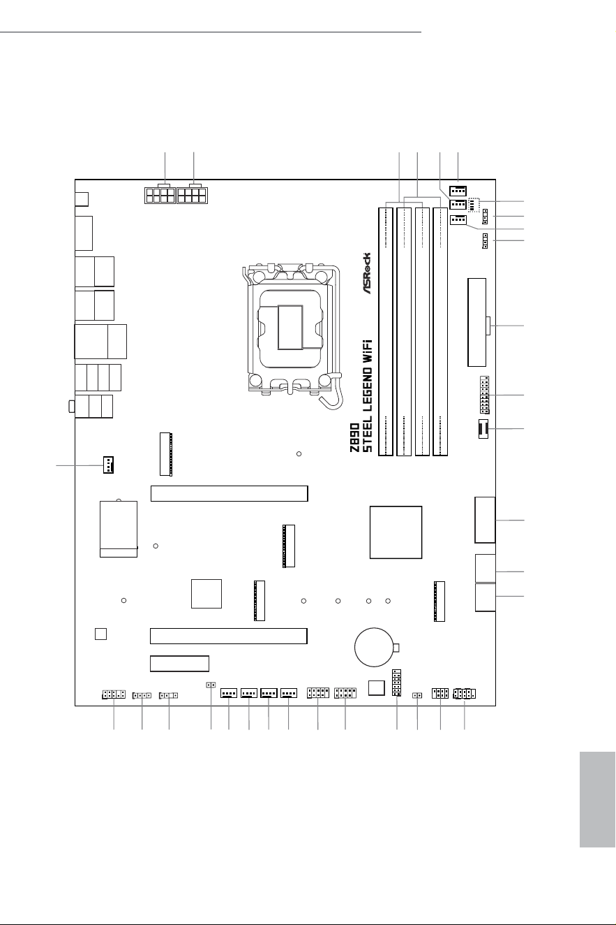
1.3 Motherboard Layout

English
8
No. Description
1 ATX 12V Power Connector (ATX12V1)
2 ATX 12V Power Connector (ATX12V2)
3 2 x 288-pin DDR5 DIMM Slots (DDR5_A1, DDR5_B1)
4 2 x 288-pin DDR5 DIMM Slots (DDR5_A2, DDR5_B2)
5 CPU Fan Connector (CPU_FAN2)
6 CPU Fan Connector (CPU_FAN1)
7 Post Status Checker (PSC)
8 Addressable LED Header (ADDR_LED3)
9 AIO Pump Fan Connector (AIO_PUMP)
10 Addressable LED Header (ADDR_LED2)
11 ATX Power Connector (ATXPWR1)
12 USB 3.2 Gen1 Header (USB32_9_10)
13 Front Panel Type C USB 3.2 Gen2x2 Header (USB32_TC2)
14 USB 3.2 Gen1 Header (USB32_7_8)
15 SATA3 Connectors (SATA3_2)(Upper), (SATA3_3)(Lower)
16 SATA3 Connectors (SATA3_0)(Upper), (SATA3_1)(Lower)
17 System Panel Header (PANEL1)
18 Power LED and Speaker Header (SPK_PLED1)
19 Clear CMOS Jumper (CLRMOS1)
20 SPI TPM Header (SPI_TPM_J1)
21 USB 2.0 Header (USB_5_6)
22 USB 2.0 Header (USB_3_4)
23 Chassis Fan Connector (CHA_FAN1)
24 Chassis Fan Connector (CHA_FAN2)
25 Chassis Fan Connector (CHA_FAN3)
26 Chassis Fan Connector (CHA_FAN4)
27 hermistor Cable Header (T_SENSOR1)
28 Addressable LED Header (ADDR_LED1)
29 RGB LED Header (RGB_LED1)
30 Front Panel Audio Header (HD_AUDIO1)
31 Chassis Fan Connector (CHA_FAN5)
English
9
Z890 Steel Legend WiFi
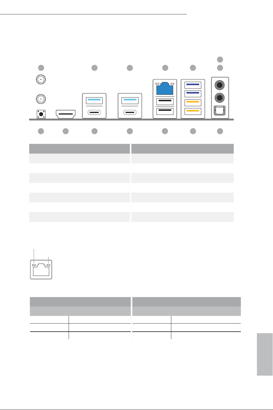
1.4 I/O Panel
10
1113
4
9
7
6
8
12
2
14
1
3
5
No. Description No. Description
1 Antenna Ports 8 Optical SPDIF Out Port
2 USB 3.2 Gen2 Port (USB32_1) 9 USB 3.2 Gen1 Ports (USB32_34)****
3 USB 3.2 Gen2 Port (USB32_2) 10 USB 2.0 Ports (USB_12)
4 2.5G LAN RJ-45 Port* 11 hunderbolt
TM
4 Type-C Port (TB_2)
5 USB 3.2 Gen1 Ports (USB32_56)** 12 hunderbolt
TM
4 Type-C Port (TB_1)
6 Microphone Input Jack*** 13 HDMI Port
7 Line Out Jack*** 14 BIOS Flashback Button
* here are two LEDs on each LAN port. Please refer to the table below for the LAN port LED indications.
Activity / Link LED Speed LED
Status Description Status Description
Of No Link Of 10Mbps connection
Blinking Data Activity Orange 100Mbps/1Gbps connection
On Link Green 2.5Gbps connection
**Ultra USB Power is supported on USB32_56 ports. ACPI wake-up function is not supported on USB32_56 ports.
ACT/LINK LED
SPEED LED
LAN Port

English
10
*** Function of the Audio Ports in 2, 4, 5.1 or 7.1-channel Coniguration:
Channel Port Function
2ch
Line Out Jack
(Rear Panel)
Front speaker out
4ch
Pink-Mic
(Front Panel)
Rear speaker out
5.1ch
Microphone Input Jack
(Rear Panel)
Central/Subwoofer speaker out
7.1ch
Lime-Headphone
(Front Panel)
Side Speaker out
**** USB32_34 are the Lightning Gaming Ports.
English
11
Z890 Steel Legend WiFi
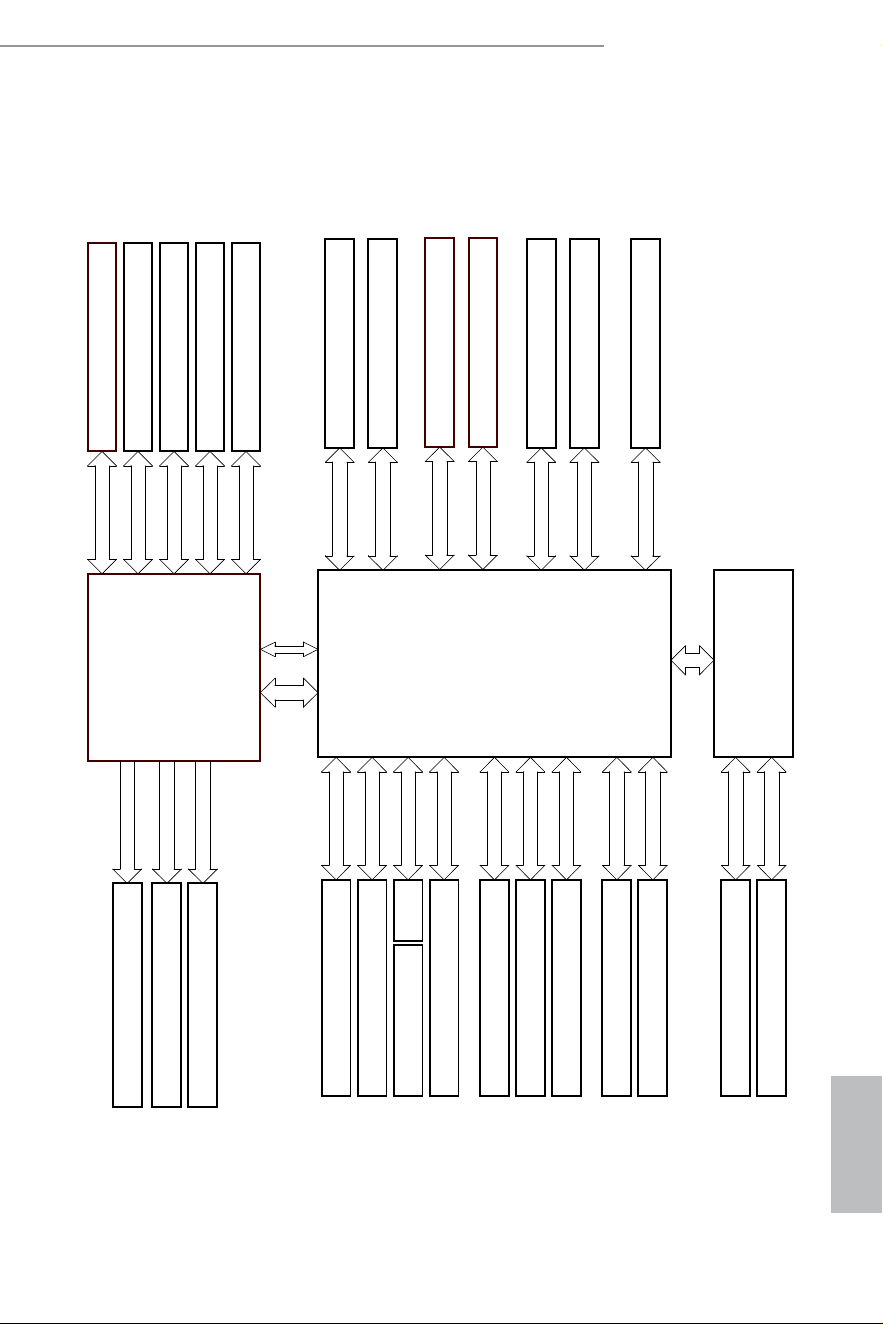
1.5 Block Diagram
Gen3 x1
Gen4 x4
Gen4 x4
PCIE3 Gen4x4 (x16 Slot )
PCIE1 ( Gen5 x16 Slot )
Intel
800 Series
Chipset
Intel Arrow Lake
Processor
Socket 1851
SATA 4 port
SATA 6Gb
5Gb/s
Rear USB 3.2 Gen1* 2 port
Channel B
Channel A
DDR5 Slot x2
DDR5 Slot x2
SIO NCT6686D
ALC1220 (2 jack + 1 SPDIF Audio)
DMI Gen4 x8
10Gb/s
Gen5 x4
Rear USB 3.2 Gen2 Type A * 2 port
M.2_1 PCIe Gen5 x4
Gen5 x16
5Gb/s
Front USB 2.0 * 4 port
480Mb/s
AZ(HD Audio)
eSPI
Realtek RTL8125BG (2.5G LAN)
FAN x8
H/W Monitor
20Gb/s
Front USB 3.2 Gen2x2 Type C
Front USB 3.2 Gen1 *4 port
SPI
Flash ROM 256Mb
Gen4 x4
M.2_2 PCIe Gen4 x4
DDI3
HDMI
TCP1
TCP0
TB1(Thunderbolt4, USB4, DP alt mode)
TB2(Thunderbolt4, USB4, DP alt mode)
Direct eSPI
Gen4 x4
Gen4 x4
M.2_4 (PCIe Gen4 x4)
M.2_3 (PCIe Gen4 x4 & SATA)
ASM3042
PCIE x1
Rear USB 3.2 Gen1 *2 port
480Mb/s
Rear USB 2.0 * 2 port
PCIE2 Gen4x4 (x16 Slot )
Gen3 x1
M2_WIFI (CNVi and PCIE)

English
12
1.6 802.11be Wi-Fi 7 Module and ASRock WiFi 2.4/5/6 GHz An-
tenna
802.11be Wi-Fi 7 + BT Module
his motherboard comes with an exclusive 802.11 a/b/g/n/ac/ax/axe/be Wi-Fi 7 + BT
v5.4 module that ofers support for 802.11 a/b/g/n/ac/ax/axe/be Wi-Fi 7 connectivity
standards and Bluetooth v5.4. Wi-Fi 7 + BT module is an easy-to-use wireless local
area network (WLAN) adapter to support Wi-Fi 7 + BT. Bluetooth v5.4 standard
features Smart Ready technology that adds a whole new class of functionality into the
mobile devices.
* he transmission speed may vary according to the environment.
* Wi-Fi 7 (6GHz band) will be supported by Microsot® Windows® 11. he availability
will depend on the diferent regulation status of each country and region. It will be
activated (for supported countries) through Windows Update and sotware updates
once available.
English
13
Z890 Steel Legend WiFi
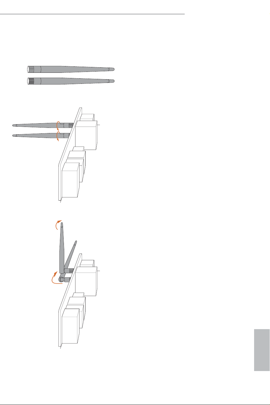
WiFi Antennas Installation Guide
Step 1
Prepare the WiFi 2.4/5/6 GHz Antennas that
come with the package.
Step 2
Connect the two WiFi 2.4/5/6 GHz Antennas
to the antenna connectors. Turn the antenna
clockwise until it is securely connected.
Step 3
Set the WiFi 2.4/5/6 GHz Antenna as shown in
the illustration.
*You may need to adjust the direction of
the antenna for a stronger signal.

English
14
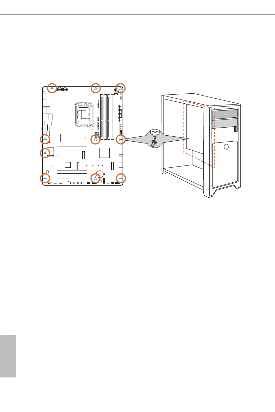
his is an ATX form factor motherboard. Before you install the motherboard, study
the coniguration of your chassis to ensure that the motherboard its into it.
Pre-installation Precautions
Take note of the following precautions before you install motherboard components
or change any motherboard settings.
•
Make sure to unplug the power cord before installing or removing the motherboard
components. Failure to do so may cause physical injuries and damages to motherboard
components.
•
In order to avoid damage from static electricity to the motherboard’s components,
NEVER place your motherboard directly on a carpet. Also remember to use a grounded
wrist strap or touch a safety grounded object before you handle the components.
•
Hold components by the edges and do not touch the ICs.
•
Whenever you uninstall any components, place them on a grounded anti-static pad or
in the bag that comes with the components.
•
When placing screws to secure the motherboard to the chassis, please do not over-
tighten the screws! Doing so may damage the motherboard.
Chapter 2 Installation
English
15
Z890 Steel Legend WiFi
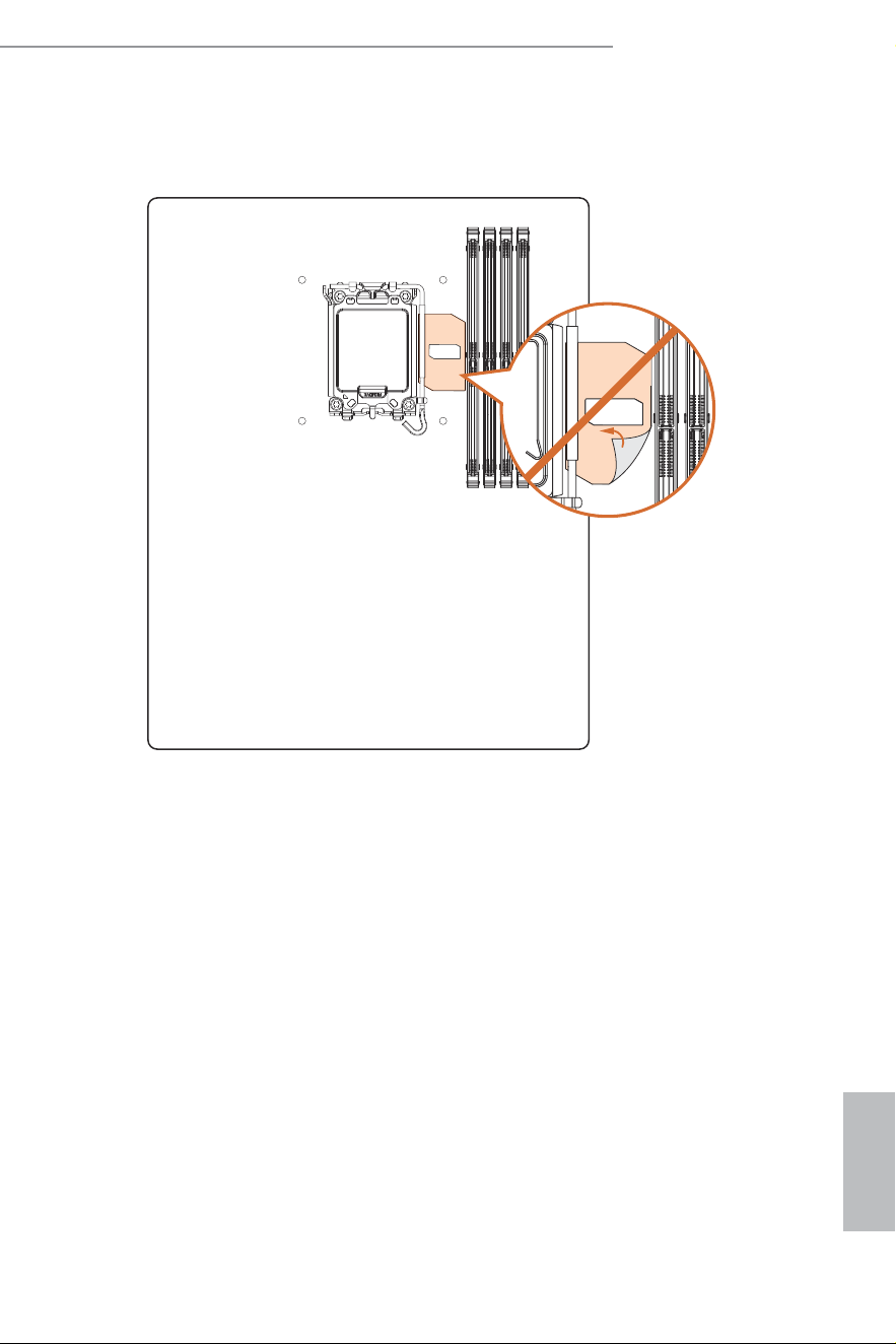
DO NOT remove this Memory OC Shield (patent pending) from the motherboard.
Removing this may afect memory overclocking performance and stability.
he illustration shown here is for reference only and may not be an exact representation of your mother-
board’s layout.
English
16
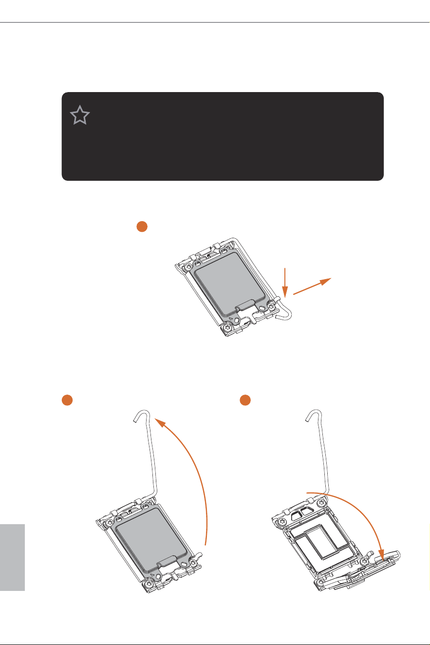
2.1 Installing the CPU
1. Before you insert the 1851-Pin CPU into the socket, please check if the PnP cap is on the
socket, if the CPU surface is unclean, or if there are any bent pins in the socket. Do not
force to insert the CPU into the socket if above situation is found. Otherwise, the CPU
will be seriously damaged.
2. Unplug all power cables before installing the CPU to prevent hardware damage.
3. Use the CPU cooler with a minimum of 35lb of static compressive load for the LGA1851
RL-ILM (Reduced Load Independent Loading Mechanism) socket.
1
A
B
2 3
English
17
Z890 Steel Legend WiFi
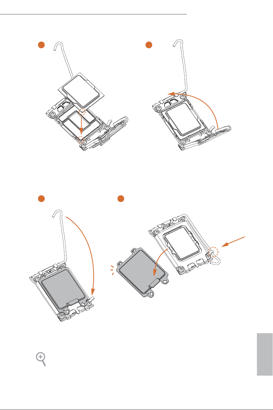
5
76
4
Please save and replace the cover if the processor is removed. he cover must be placed if
you wish to return the motherboard for ater service.
English
18
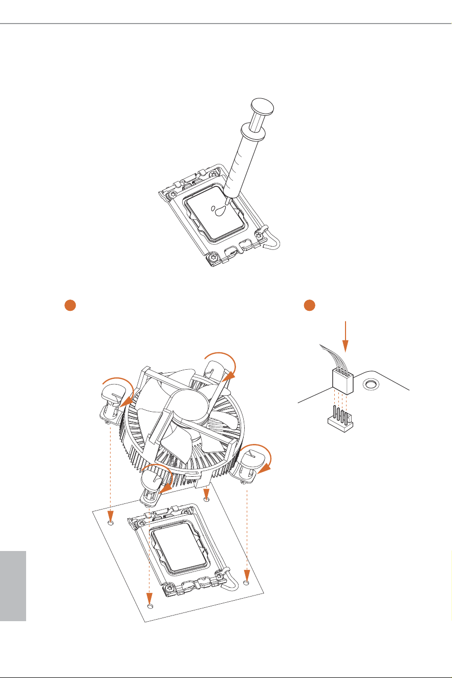
2.2 Installing the CPU Fan and Heatsink
1 2
CPU_FAN

English
19
Z890 Steel Legend WiFi
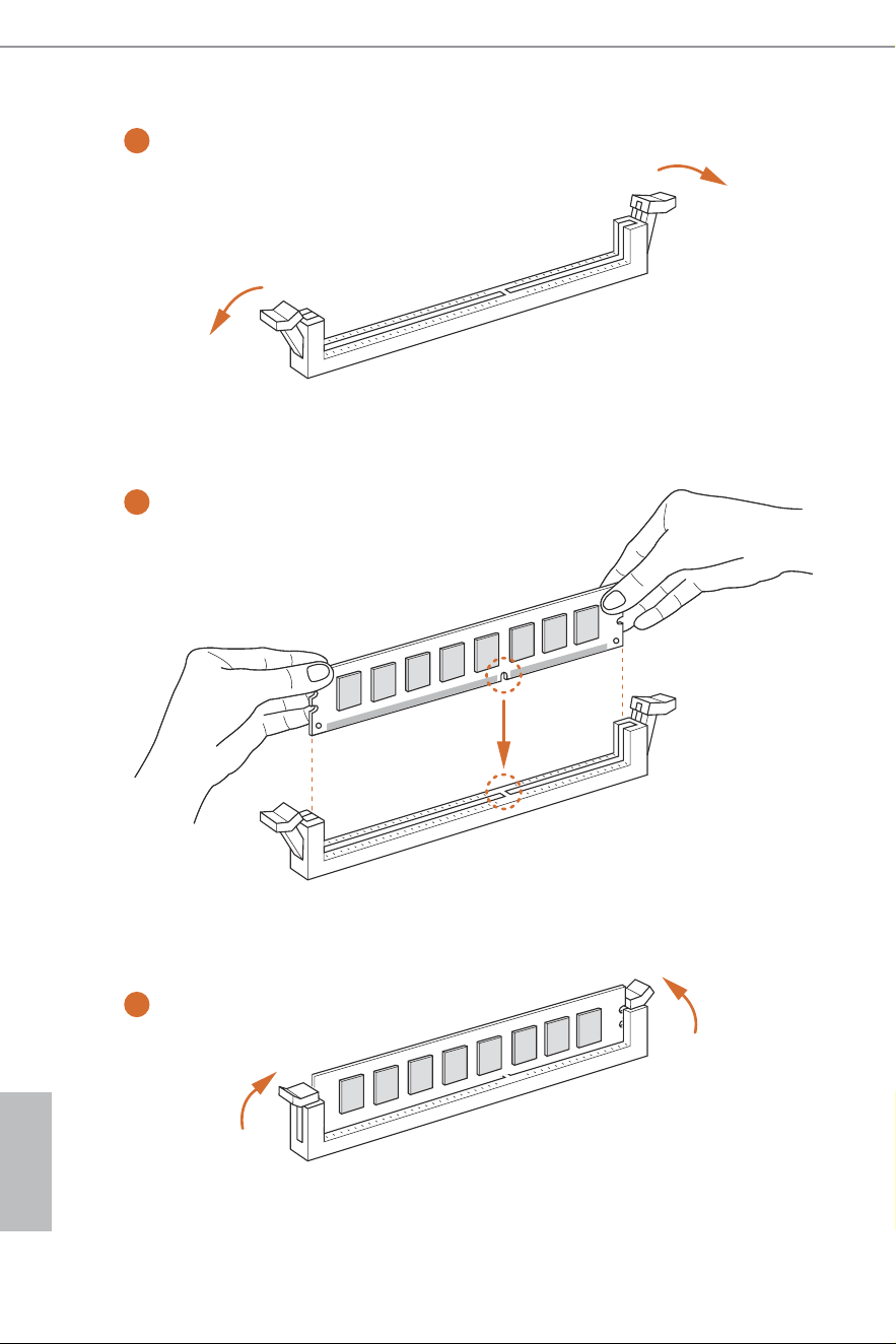
2.3 Installing Memory Modules (DIMM)
his motherboard provides four 288-pin DDR5 (Double Data Rate 5) DIMM slots,
and supports Dual Channel Memory Technology.
Recommended Memory Coniguration
1 DIMM
2 DIMMs
4 DIMMs
A1 A2 B1 B2
V
A1 A2 B1 B2
V V
A1 A2 B1 B2
V V V V
1. For dual channel coniguration, you always need to install identical (the same brand,
speed, size and chip-type) DDR5 DIMM pairs.
2. It is unable to activate Dual Channel Memory Technology with only one or three memory
module installed.
3. It is not allowed to install a DDR, DDR2 , DDR3 or DDR4 memory module into a DDR5
slot; otherwise, this motherboard and DIMM may be damaged.
4. he DIMM only its in one correct orientation. It will cause permanent damage to the
motherboard and the DIMM if you force the DIMM into the slot at incorrect orientation.
English
20
1
2
3
English
21
Z890 Steel Legend WiFi
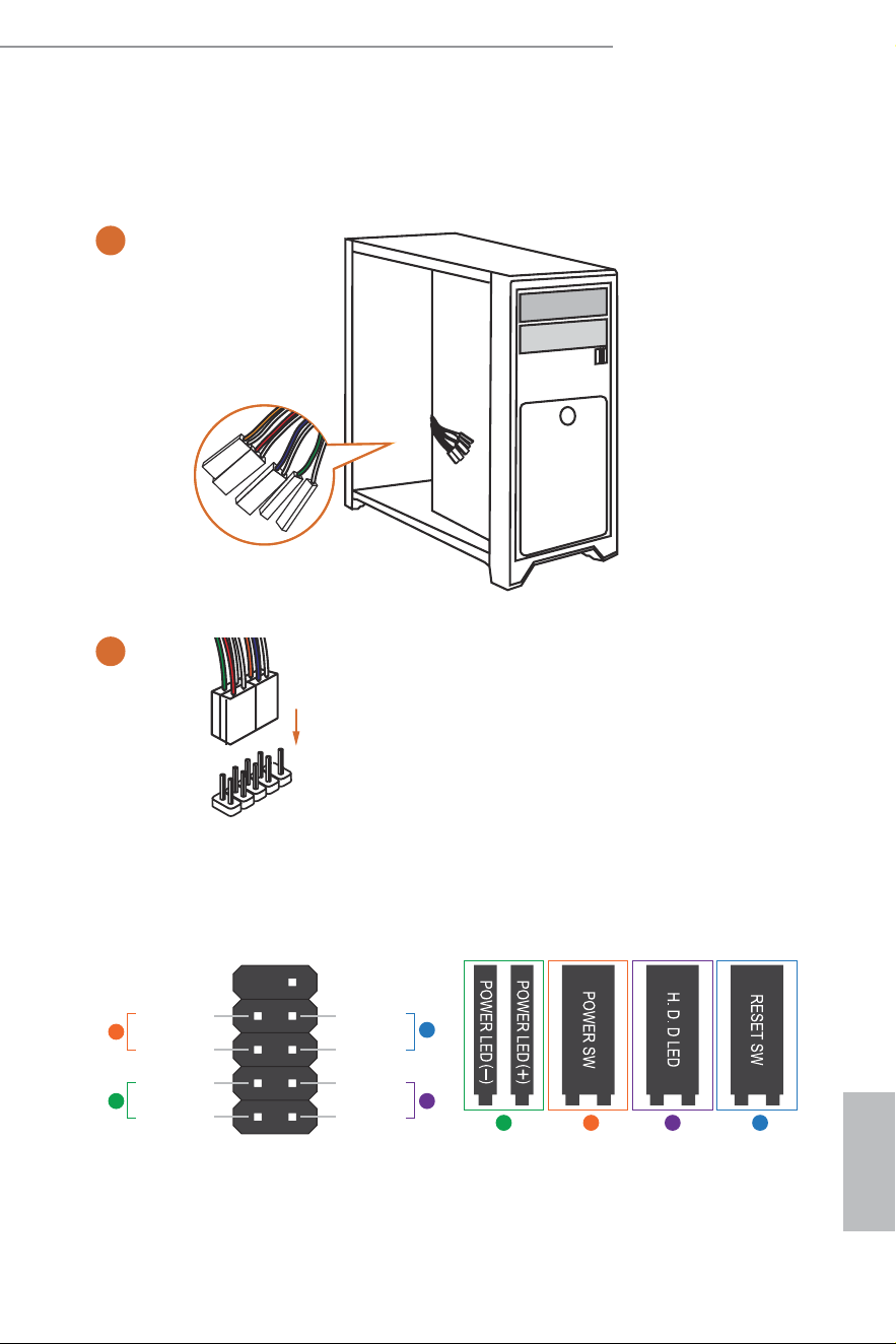
2.4 Connecting the Front Panel Header
ABC D
1
2
32:(56:
5(6(76:
32:(5/('
32:(5/('
+''/('
3$1(/
Power SW (-) RESET SW (+)
HDD LED (-)
HDD LED (+)
12
910
RESET SW (-)Power SW (+)
Power LED (-)
Power LED (+)
A
B
C
D
PANEL1
HDD LED
RESET SW
System Panel Header
Front Panel Wires
English
22
2.5 Installing the Motherboard
English
23
Z890 Steel Legend WiFi
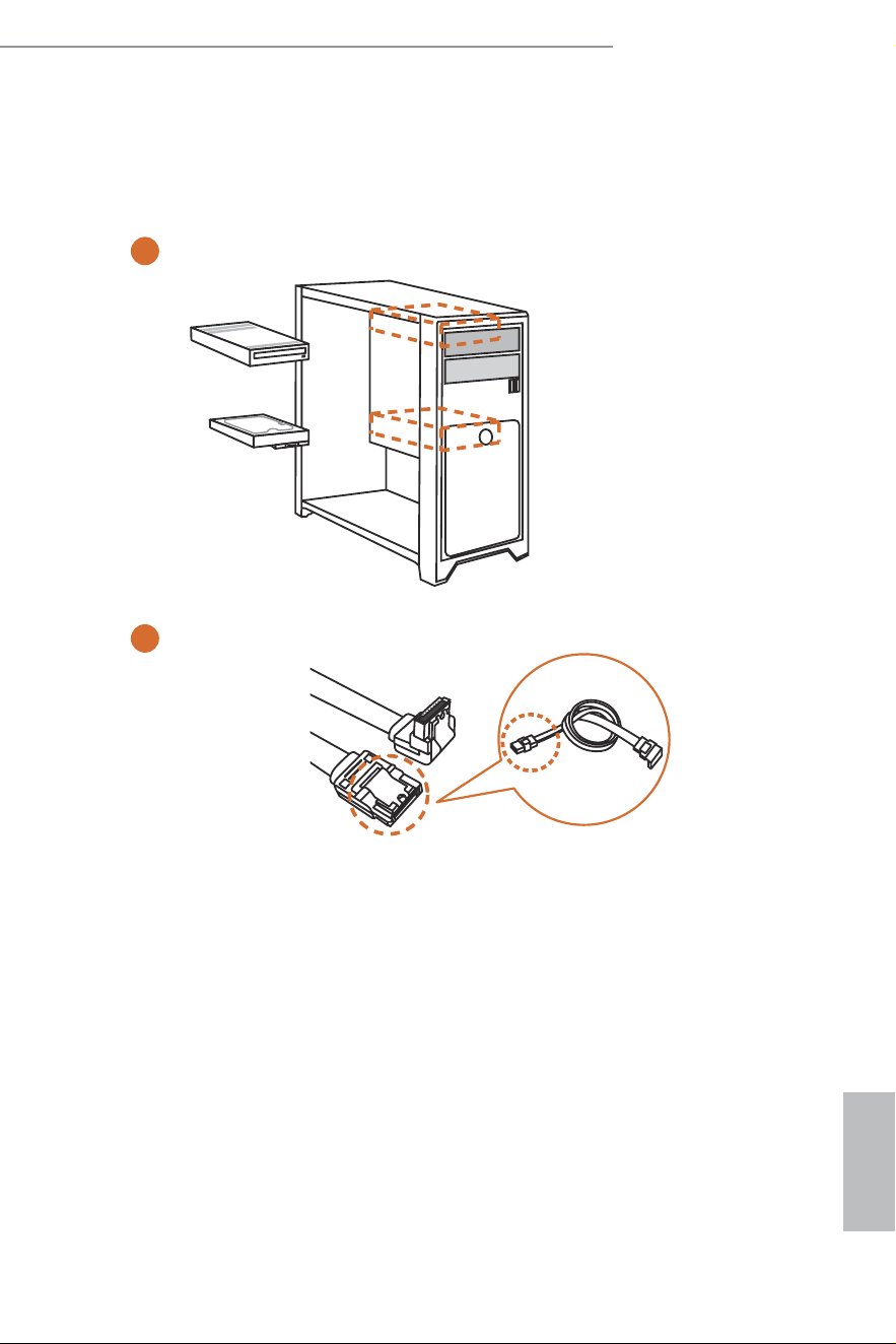
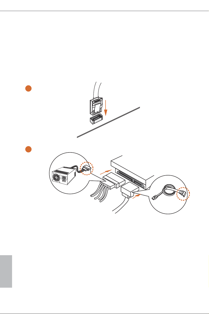
2.6 Installing SATA Drives
1
2
Optical Drive
SATA Drive
SATA Data Cable
English
24
3
4
SATA Power Connector
SATA Data Connector
English
25
Z890 Steel Legend WiFi
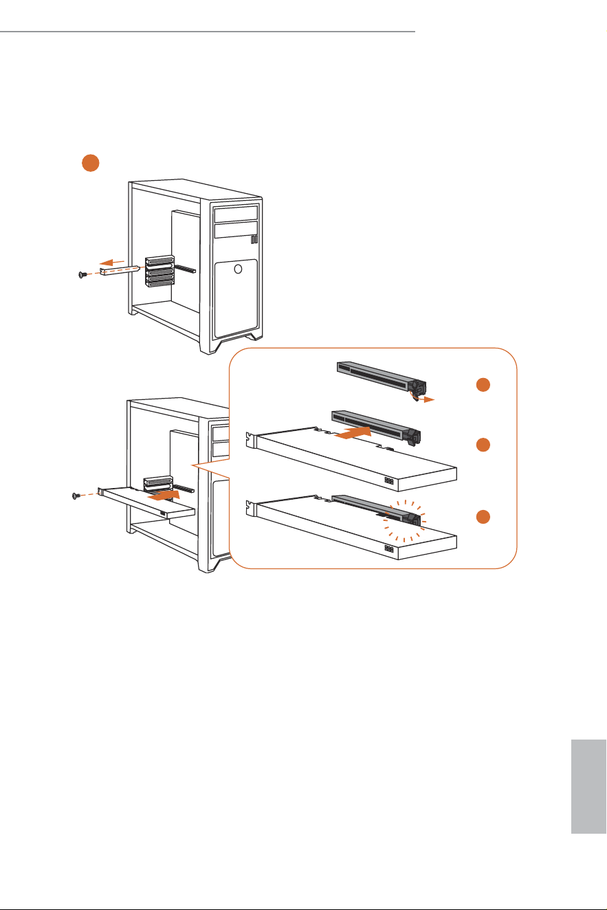
2.7 Installing a Graphics Card
1
1
CLICK!
2
3
4

English
26
Expansion Slots (PCIe Slots)
here are 3 PCI Express slots on the motherboard.
PCIe slots:
PCIE1 (PCIe 5.0 x16 slot) is used for PCIe x16 lane width graphics cards.
PCIE2 (PCIe 4.0 x16 slot) is used for PCIe x4 lane width graphics cards.
PCIE3 (PCIe 4.0 x4 slot) is used for PCIe x4 lane width graphics cards.
* PCIE1 supports PCIe riser cards to extend one x16 slot to x8/x8 or x8/x4/x4 slots.
Before installing an expansion card, please make sure that the power supply is switched of
or the power cord is unplugged. Please read the documentation of the expansion card and
make necessary hardware settings for the card before you start the installation.
English
27
Z890 Steel Legend WiFi
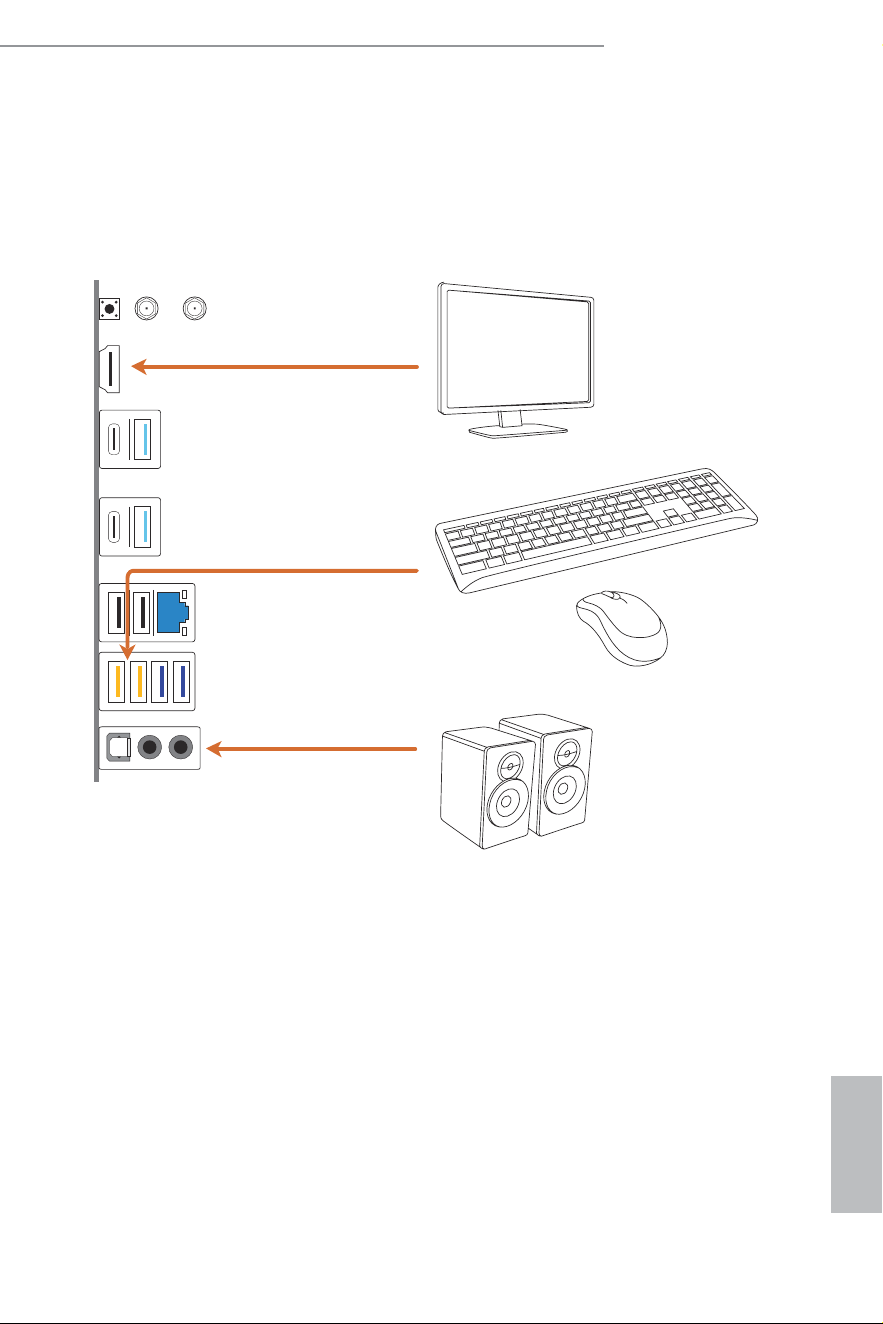
2.8 Connecting Peripheral Devices
English
28
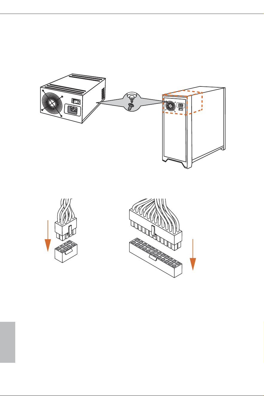
2.9 Connecting the Power Connectors
$7;3:5
$7;9
English
29
Z890 Steel Legend WiFi
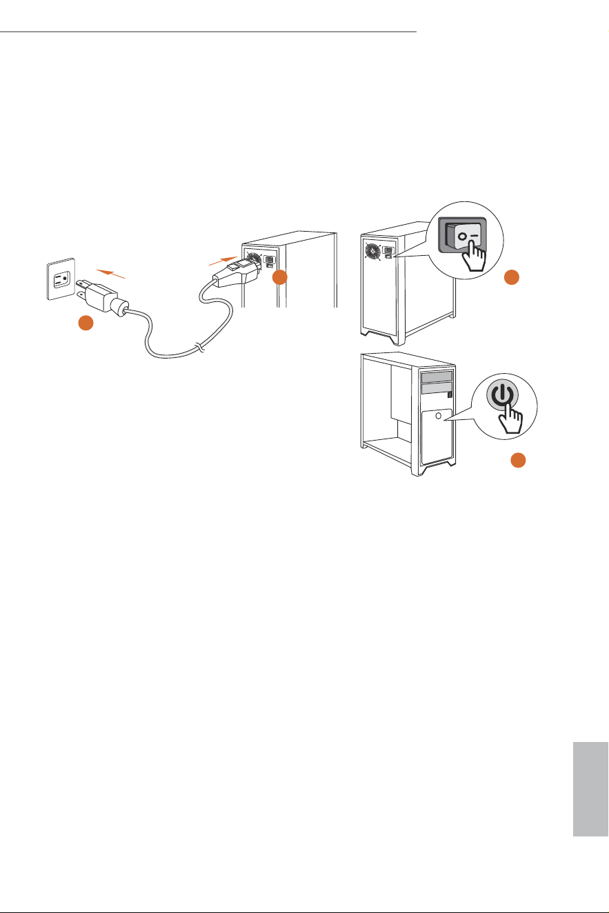
2.10 Power On
2
3
4
1
English
30
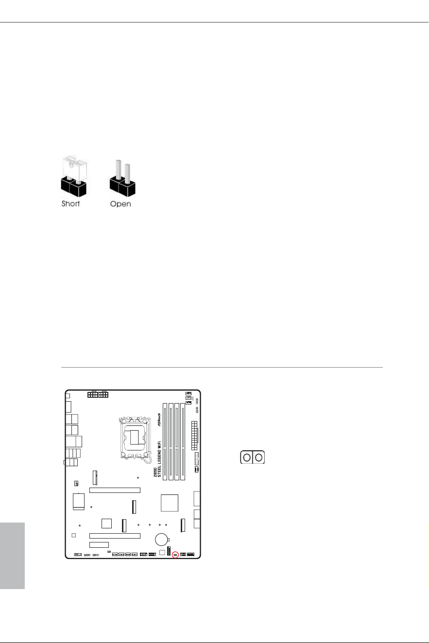
2.11 Jumpers Setup
he illustration shows how jumpers are setup. When the jumper cap is placed on
the pins, the jumper is “Short”. If no jumper cap is placed on the pins, the jumper is
“Open”.
Clear CMOS Jumper
(CLRMOS1) (see p.7, No. 19)
CLRMOS1 allows you to clear the data in CMOS. he data in CMOS includes
system setup information such as system password, date, time, and system setup
parameters. To clear and reset the system parameters to default setup, please turn
of the computer and unplug the power cord, then use a jumper cap to short the
pins on CLRMOS1 for 3 seconds. Please remember to remove the jumper cap ater
clearing the CMOS. If you need to clear the CMOS when you just inish updating
the BIOS, you must boot up the system irst, and then shut it down before you do
the clear-CMOS action.
CLRMOS1
2-pin Jumper
Short: Clear CMOS
Open: Default
English
31
Z890 Steel Legend WiFi
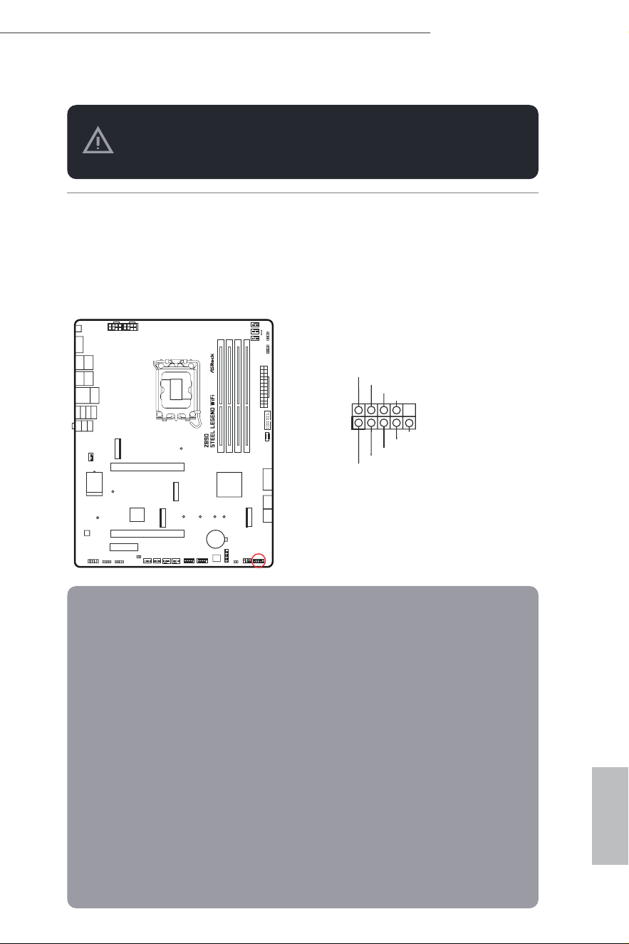
2.12 Onboard Headers and Connectors
System Panel Header
(9-pin PANEL1) (see p.7, No. 17)
Connect the power button, reset button and system status indicator on the chassis
to this header according to the pin assignments below. Note the positive and
negative pins before connecting the cables.
GND
RESET#
PWRBTN#
PLED-
PLED+
GND
HDLED-
HDLED+
1
GND
PANEL1
Onboard headers and connectors are NOT jumpers. Do NOT place jumper caps over these
headers and connectors. Placing jumper caps over the headers and connectors will cause
permanent damage to the motherboard.
PWRBTN (Power Button):
Connect to the power button on the chassis front panel. You may conigure the way to turn
of your system using the power button.
RESET (Reset Button):
Connect to the reset button on the chassis front panel. Press the reset button to restart the
computer if the computer freezes and fails to perform a normal restart.
PLED (System Power LED):
Connect to the power status indicator on the chassis front panel. he LED is on when the
system is operating. he LED keeps blinking when the system is in S1/S3 sleep state. he
LED is of when the system is in S4 sleep state or powered of (S5).
HDLED (Hard Drive Activity LED):
Connect to the hard drive activity LED on the chassis front panel. he LED is on when the
hard drive is reading or writing data.
he front panel design may difer by chassis. A front panel module mainly consists of power
button, reset button, power LED, hard drive activity LED, speaker and etc. When connect-
ing your chassis front panel module to this header, make sure the wire assignments and the
pin assignments are matched correctly.
English
32
Power LED and Speaker Header
(7-pin SPK_PLED1) (see p.7, No. 18)
Please connect the chassis power LED and the chassis speaker to this header.
1
+5V
DUMMY
PLED+
PLED+
PLED-
DUMMY
SPEAKER
SPK_PLED1
English
33
Z890 Steel Legend WiFi
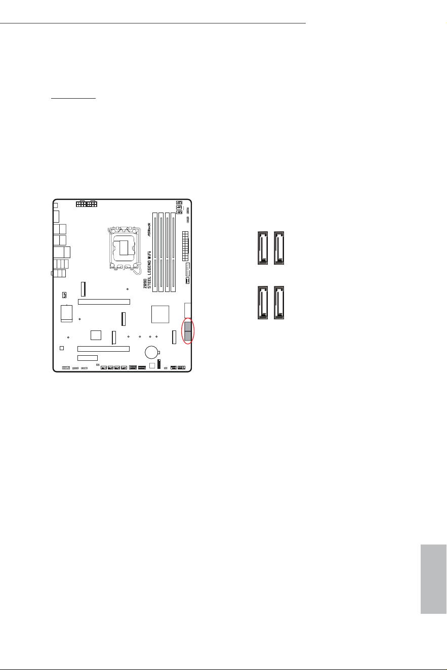
Serial ATA3 Connectors
Right Angle:
(SATA3_0) (see p.7, No. 16)(Upper)
(SATA3_1) (see p.7, No. 16)(Lower)
(SATA3_2) (see p.7, No. 15)(Upper)
(SATA3_3) (see p.7, No. 15)(Lower)
hese four SATA3 connectors support SATA data cables for internal storage devices with
up to 6.0 Gb/s data transfer rate.
SATA3_2SATA3_0
SATA3_3SATA3_1
English
34
USB 2.0 Headers
(9-pin USB_3_4) (see p.7, No. 22)
(9-pin USB_5_6) (see p.7, No. 21)
here are two headers on this motherboard. Each USB 2.0 header can support two
ports.
DUMMY
GND
GND
P+
P-
USB_PWR
P+
P-
USB_PWR
1
USB_3_4
DUMMY
GND
GND
P+
P-
USB_PWR
P+
P-
USB_PWR
1
USB_5_6
English
35
Z890 Steel Legend WiFi
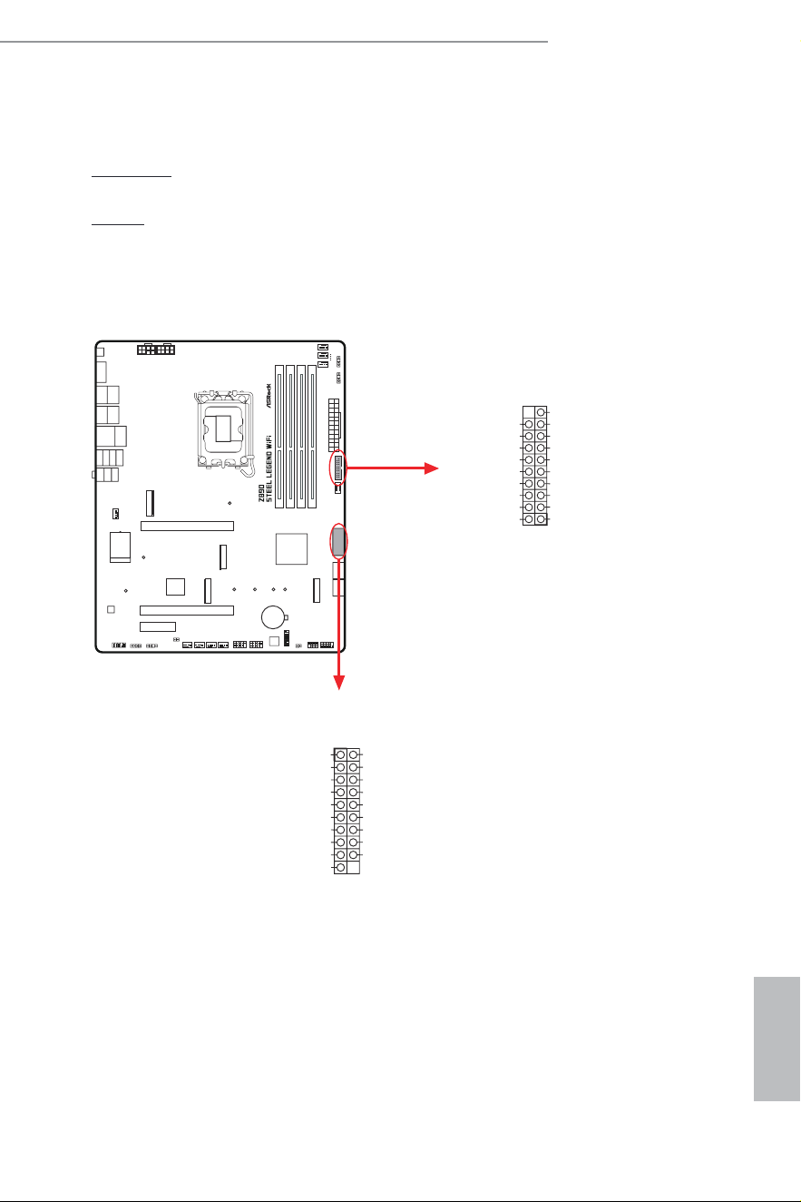
USB 3.2 Gen1 Headers
Right Angle:
(19-pin USB32_7_8) (see p.7, No. 14)
Vertical:
(19-pin USB32_9_10) (see p.7, No. 12)
here are two headers on this motherboard. Each USB 3.2 Gen1 header can
support two ports.
1
IntA_PB_D+
Dummy
IntA_PB_D-
GND
IntA_PB_SSTX+
GND
IntA_PB_SSTX-
IntA_PB_SSRX+
IntA_PB_SSRX-
VbusVbus
Vbus
IntA_PA_SSRX-
IntA_PA_SSRX+
GND
IntA_PA_SSTX-
IntA_PA_SSTX+
GND
IntA_PA_D-
IntA_PA_D+
1
IntA_PB_D+
Dummy
IntA_PB_D-
GND
IntA_PB_SSTX+
GND
IntA_PB_SSTX-
IntA_PB_SSRX+
IntA_PB_SSRX-
VusbV
Vusb
IntA_PA_SSRX-
IntA_PA_SSRX+
GND
IntA_PA_SSTX-
IntA_PA_SSTX+
GND
IntA_PA_D-
IntA_PA_D+
USB32_9_10
USB32_7_8
English
36
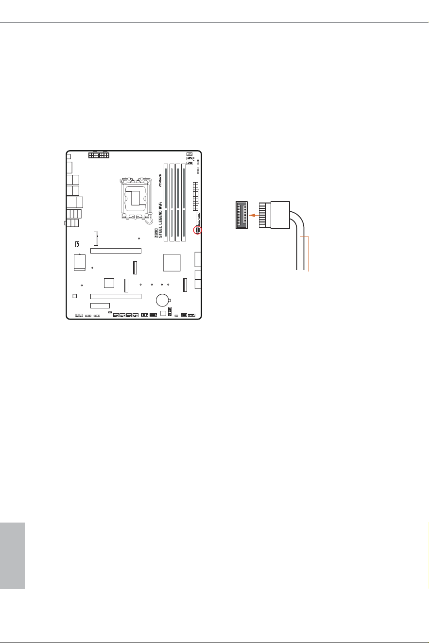
Front Panel Type C USB 3.2 Gen2x2 Header
(20-pin USB32_TC2) (see p.7, No. 13)
here is one Front Panel Type C USB 3.2 Gen2x2 Header on this motherboard.
his header is used for connecting a USB 3.2 Gen2x2 module for additional USB 3.2
Gen2x2 ports.
USB32_TC2
USB Type-C Cable
English
37
Z890 Steel Legend WiFi
Front Panel Audio Header
(9-pin HD_AUDIO1) (see p.7, No. 30)
his header is for connecting audio devices to the front audio panel.
HD_AUDIO1
High Deinition Audio supports Jack Sensing, but the panel wire on the chassis must sup-
port HDA to function correctly. Please follow the instructions in our manual and chassis
manual to install your system.
J_SENSE
OUT2_L
1
MIC_RET
PRESENCE#
GND
OUT2_R
MIC2_R
MIC2_L
OUT_RET
English
38
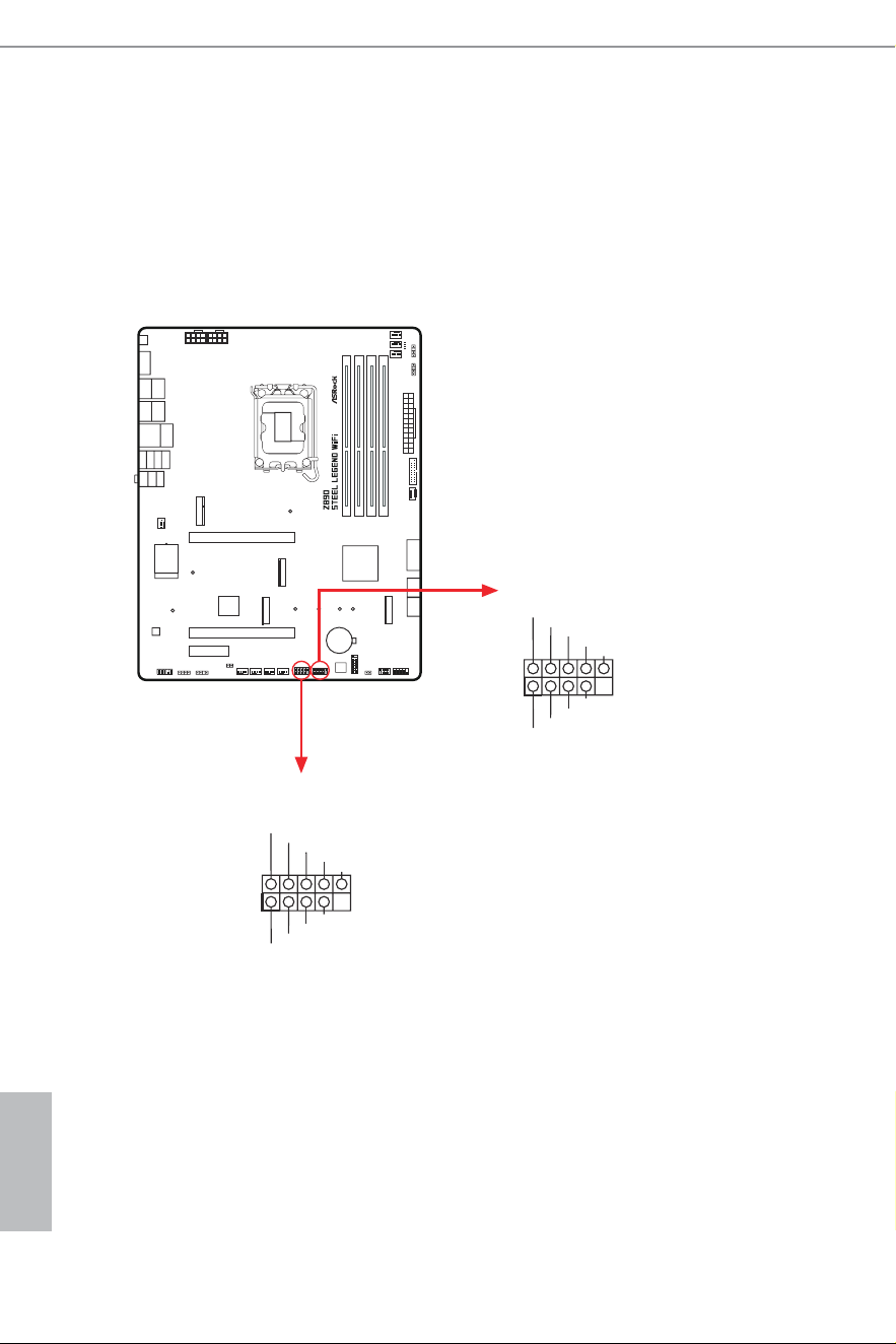
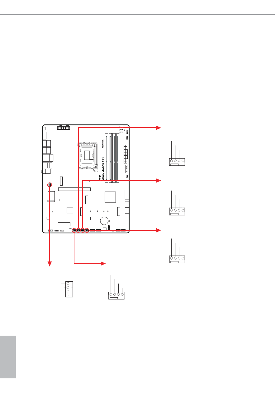
Chassis Fan Connectors
(4-pin CHA_FAN1) (see p.7, No. 23)
(4-pin CHA_FAN2) (see p.7, No. 24)
(4-pin CHA_FAN3) (see p.7, No. 25)
(4-pin CHA_FAN4) (see p.7, No. 26)
(4-pin CHA_FAN5) (see p.7, No. 31)
hese headers allow you to connect Case or Radiator fans. If you plan to connect a
3-pin fan, please connect it to Pin 1-3.
CHA_FAN4
GND
CHA_FAN_SPEED
FAN_SPEED_CONTRO
L
FAN_VOLTAGE
1 2 3 4
CHA_FAN2
CHA_FAN5
CHA_FAN1
GND
CHA_FAN_SPEED
FAN_SPEED_CONTROL
FAN_VOLTAGE
1 2 3 4
CHA_FAN3
GND
FAN_VOLTAGE
CHA_FAN_SPEED
F
AN_SPEED_CONTROL 4
3
2
1
GN
D
CHA_FAN_SPEED
FAN_SPEED_CONTROL
FAN_VOLTAGE
1 2 3 4
GND
CHA_FAN_SPEED
FAN_SPEED_CONTROL
FAN_VOLTAGE
1 2 3 4
English
39
Z890 Steel Legend WiFi
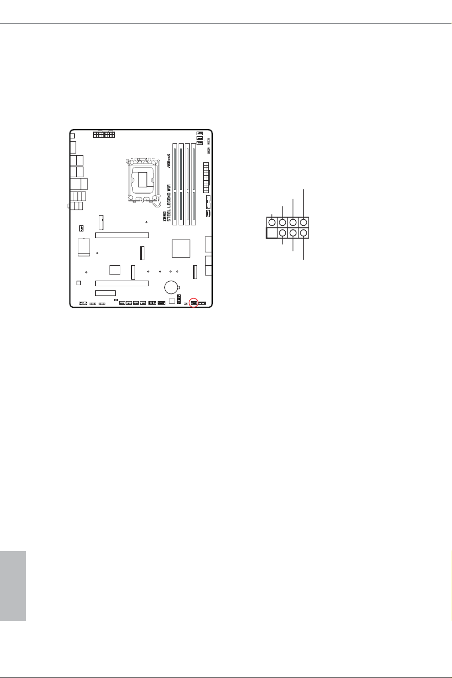
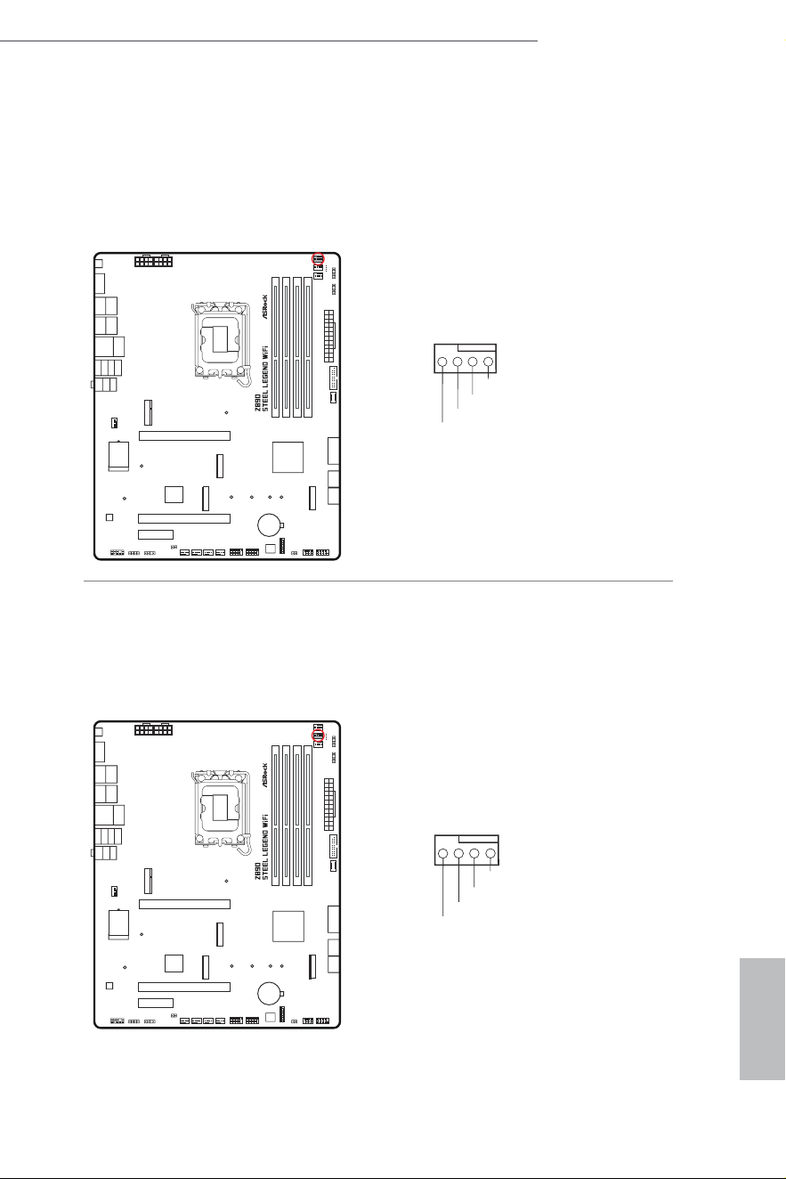
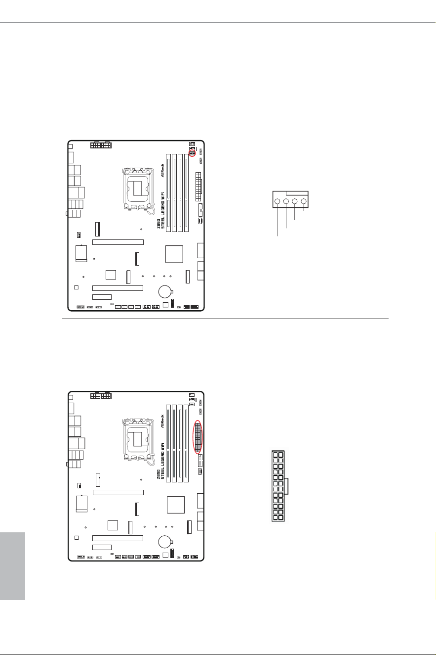
CPU Fan Connector
(4-pin CPU_FAN1) (see p.7, No. 6)
his header allows you to connect CPU fan. If you plan to connect a 3-pin fan,
please connect it to Pin 1-3.
CPU Fan Connector
(4-pin CPU_FAN2) (see p.7, No. 5)
his header allows you to connect CPU fan or Water Pump. If you plan to connect
a 3-pin fan, please connect it to Pin 1-3.
CPU_FAN1
CPU_F
+12V
GND
AN_SPEED
FAN_SPEED_CONTROL
4 3 2 1
CPU_FAN2
CPU_F
FAN_VOLTAGE
GND
AN_SPEED
FAN_SPEED_CONTROL
4 3 2 1
English
40
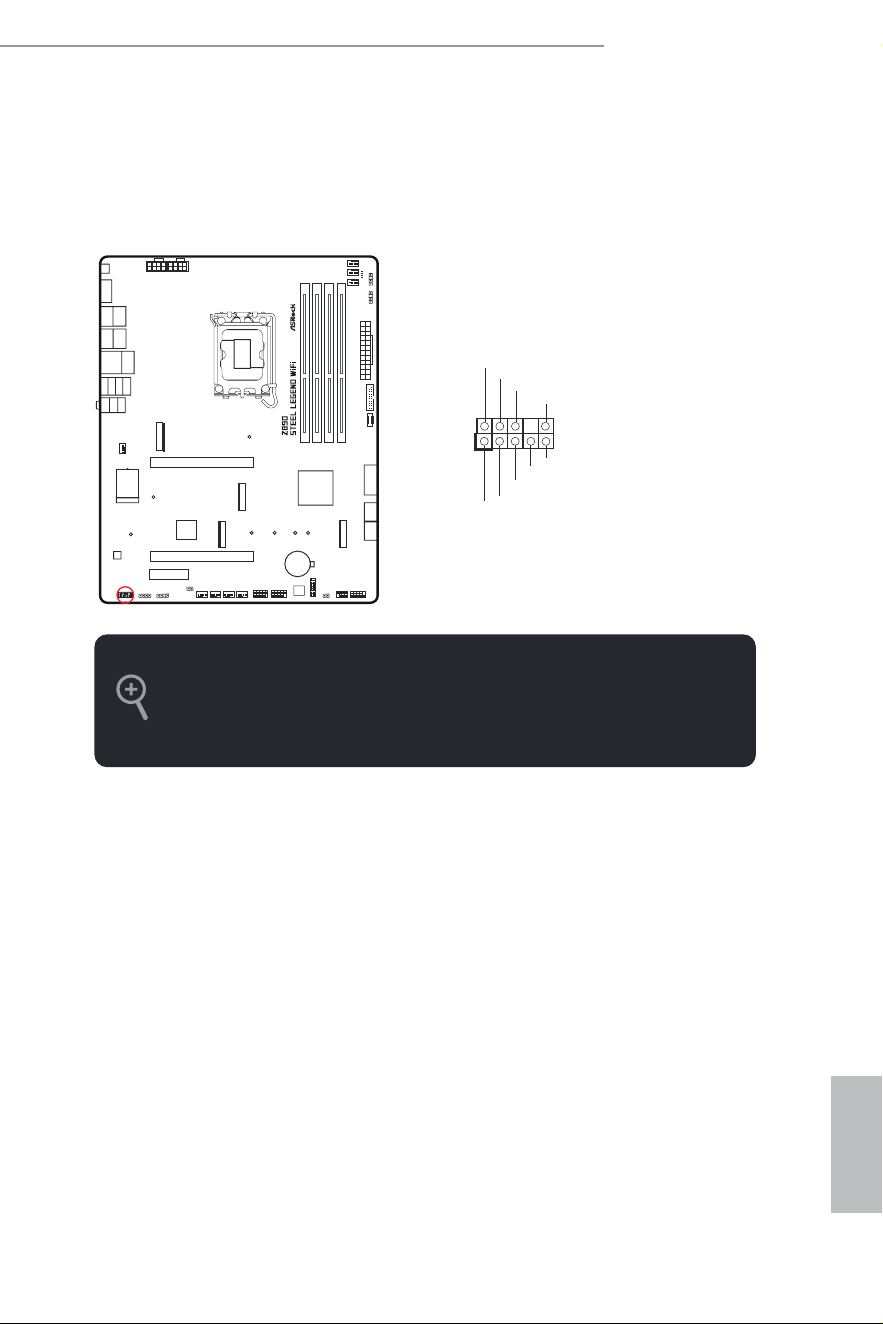
AIO Pump Fan Connector
(4-pin AIO_PUMP) (see p.7, No. 9)
his header allows you to connect AIO (All-in-One) pump or fan. If you plan to
connect a 3-pin AIO cooler fan, please connect it to Pin 1-3.
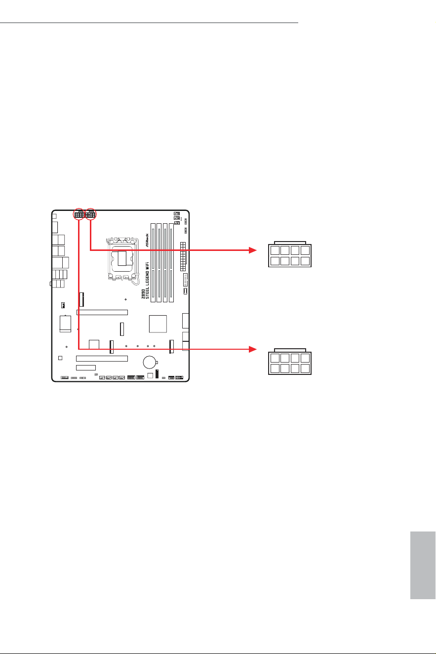
ATX Power Connector
(24-pin ATXPWR1) (see p.7, No. 11)
his motherboard provides a 24-pin ATX power connector. To use a 20-pin ATX
power supply, please plug it along Pin 1 and Pin 13.
ATXPWR1
12
1
24
13
AIO_PUMP
FAN_VOLTAGE
GND
AIO_PUMP_SPEED
FAN_SPEED_CONTROL
4 3 2 1
English
41
Z890 Steel Legend WiFi
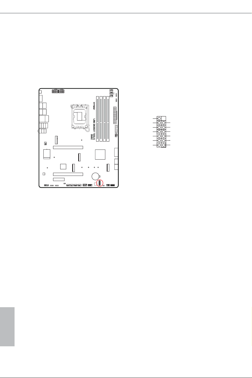
ATX 12V Power Connectors
(8-pin ATX12V1) (see p.7, No. 1)
(8-pin ATX12V2) (see p.7, No. 2)
his motherboard provides two 8-pin ATX 12V power connectors. To use a 4-pin
ATX power supply, please plug it along Pin 1 and Pin 5.
*Connecting an ATX 12V 8-pin cable to ATX12V2 is optional.
*Warning: Please make sure that the power cable connected is for the CPU and
not the graphics card. Do not plug the PCIe power cable to this
connector.
ATX12V2
ATX12V1
5
1
8
4
5
1
8
4
English
42
SPI TPM Header
(13-pin SPI_TPM_J1) (see p.7, No. 20)
his connector supports SPI Trusted Platform Module (TPM) system, which can securely
store keys, digital certiicates, passwords, and data. A TPM system also helps enhance
network security, protects digital identities, and ensures platform integrity.
SPI_TPM_J1
1
SPI_DQ3
SPI_PWR
SPI_DQ2
SPI_CS0
Dummy
CLK
SPI_MISO
SPI_MOSI
GND
SPI_TPM_CS#
RST#
RSMRST#
T
PM_PIRQ
English
43
Z890 Steel Legend WiFi
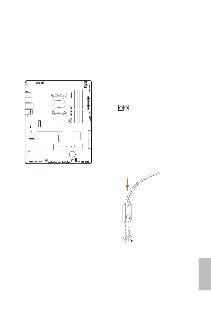
hermistor Cable Header
(2-pin T_SENSOR1) (see p.7, No. 27)
he hermistor Cable Header is used to connect a thermistor cable to monitor the
temperature of the critical component. Plug the thermistor cable that comes with the
package to the header, and then attach the sensor end to the component to detect the
temperature.
Connect your
hermistor Cable
to the
hermistor Cable Header
(
T_SENSOR1)
on
the motherboard.
T
_SENSOR
T_SENSOR1
SENSOR IN
GND
1
English
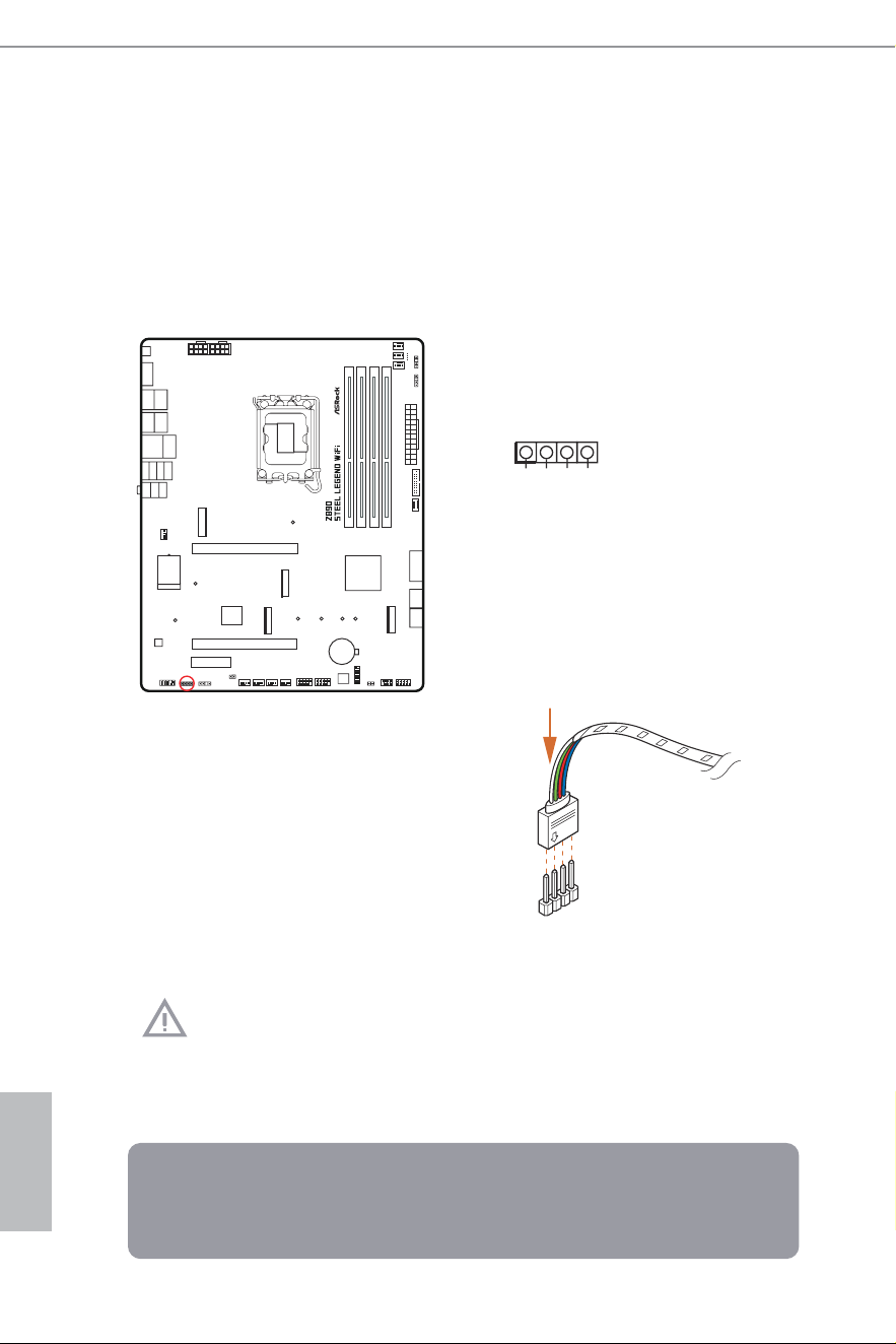
44
RGB LED Header
(4-pin RGB_LED1) (see p.7, No. 29)
his RGB header is used to connect RGB LED extension cable which allow users to choose
from various LED lighting efects.
Caution: Never install the RGB LED cable in the wrong orientation; otherwise, the
cable may be damaged.
1. Never install the RGB LED cable in the wrong orientation; otherwise, the cable
may be damaged.
2. Before installing or removing your RGB LED cable, please power of your system
and unplug the power cord from the power supply. Failure to do so may cause dam-
ages to motherboard components.
1. Please note that the RGB LED strips do not come with the package.
2. he RGB LED header supports standard 5050 RGB LED strip (12V/G/R/B), with a
maximum power rating of 3A (12V) and length within 2 meters.
1
2
V
G
R
B
1
RGB_LED1
12V GRB
1
Connect your RGB LED strip to the
RGB LED
Header
(
RGB_LED1)
on the motherboard.
English
45
Z890 Steel Legend WiFi
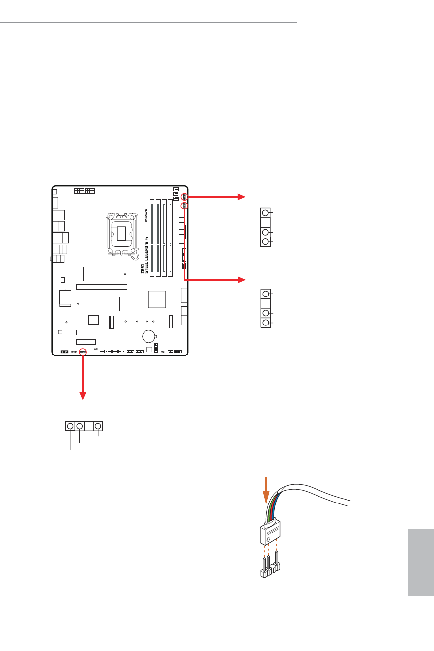
Addressable LED Headers
(3-pin ADDR_LED1) (see p.7, No. 28)
(3-pin ADDR_LED2) (see p.7, No. 10)
(3-pin ADDR_LED3) (see p.7, No. 8)
hese headers are used to connect
Addressable
LED extension cables which allow users to
choose from various LED lighting efects.
Caution: Never install the Addressable LED cable in the wrong orientation; otherwise,
the cable may be damaged.
VOUT
DO_ADDR
GN
D
1
ADDR_LED1
VOUT
DO_ADDR
GND
1
ADDR_LED3
1
Connect your
Addressable RGB LED
strips
to the
Addressable LED Headers (ADDR_
LED1 / ADDR_LED2 / ADDR_LED3)
on
the motherboard.
ADDR_LED2
VOUT
DO_ADDR
GND
1

English
46
1. Never install the Addressable LED cable in the wrong orientation; otherwise, the cable
may be damaged.
2. Before installing or removing your Addressable LED cable, please power of your system
and unplug the power cord from the power supply. Failure to do so may cause damages to
motherboard components.
1. Please note that the Addressable LED strips do not come with the package.
2. he Addressable LED header supports WS2812B addressable RGB LED strip (5V/
Data/GND), with a maximum power rating of 3A (5V) and length within 2 meters.
English
47
Z890 Steel Legend WiFi
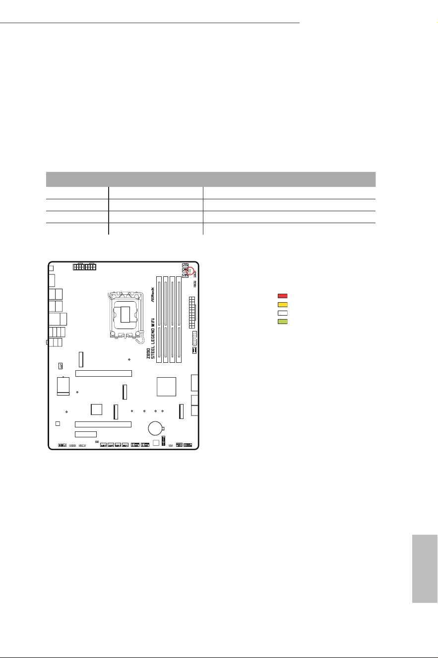
2.13 Post Status Checker
Post Status Checker (PSC) diagnoses the computer when users power on the machine.
he LEDs light up to show what component is running into an issue. hey emit red, yellow,
white and yellow-green lights to indicate, respectively, the CPU, memory, VGA and storage
are not detected or fail. hey will remain lit until the issue is ixed. he lights go of if the
four mentioned above are functioning normally.
DRAM
CPU
VGA
BOOT
Component LED Indicator Status
CPU Solid Red indicates CPU is dysfunctional.
DRAM Solid Yel low indicates DRAM is dysfunctional.
VGA Solid White indicates GPU is dysfunctional.
BOOT Solid Yellow-Green indicates boot device is dysfunctional.
English
48
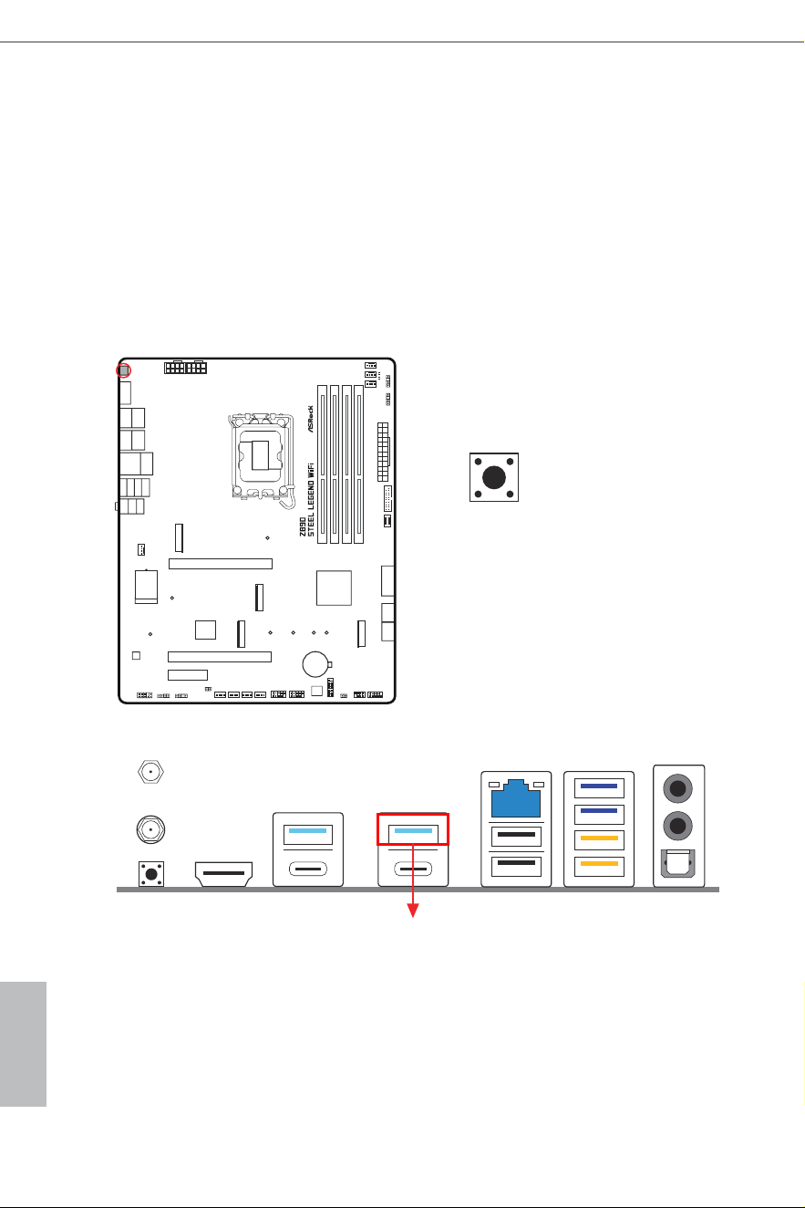
2.14 Smart Button
he motherboard has one smart switch: BIOS Flashback Button, allowing users to
lash the BIOS.
BIOS Flashback Button
(BIOS_FB1) (see p.9, No. 14)
BIOS Flashback Button allows users to lash the BIOS.
BIOS_FB1
USB BIOS Flashback port

English
49
Z890 Steel Legend WiFi
ASRock BIOS Flashback feature allows you to update BIOS without powering on the
system, even without CPU.
To use the USB BIOS Flashback function, Please follow the steps below.
1. Download the latest BIOS ile from ASRock's website : http://www.asrock.com.
2. Copy the BIOS ile to your USB lash drive. Please make sure the ile system of
your USB lash drive must be FAT32.
3. Extract BIOS ile from the zip ile.
4. Rename the ile to “creative.rom” and save it to the root directory of X: USB
lash drive.
5. Plug the 24-pin power connector to the motherboard. hen turn on the power
supply's AC switch.
*here is no need to power on the system.
6. hen plug your USB drive to the USB BIOS Flashback port.
7. Press the BIOS Flashback Switch for about three seconds. hen the LED starts
to blink.
8. Wait until the LED stops blinking, indicating that BIOS lashing has been
completed.
*If the LED light turns solid green, this means that the BIOS Flashback is not
operating properly. Please make sure that you plug the USB drive to the USB
BIOS Flashback port.
**If the LED does not light up at all
,
then please disconnect power from the
system and remove/disconnect the CMOS battery from the motherboard for
several minutes. Reconnect power and battery and try again.
9. Ater BIOS lashing is complete, turn of the PC power supply for about two
minutes.
10. hen turn on the PC power supply again and now you can press the power
button to power on the system.
Before using the BIOS Flashback function, please suspend BitLocker and any encryption
or security relying on the TPM. Make sure that you have already stored and backup-ed
the recovery key. If the recovery key is missing while encryption is active, the data will stay
encrypted and the system will not boot into the operating system. It is recommended to dis-
able fTPM before updating the BIOS. Otherwise an unpredictable failure may occur.
English
50
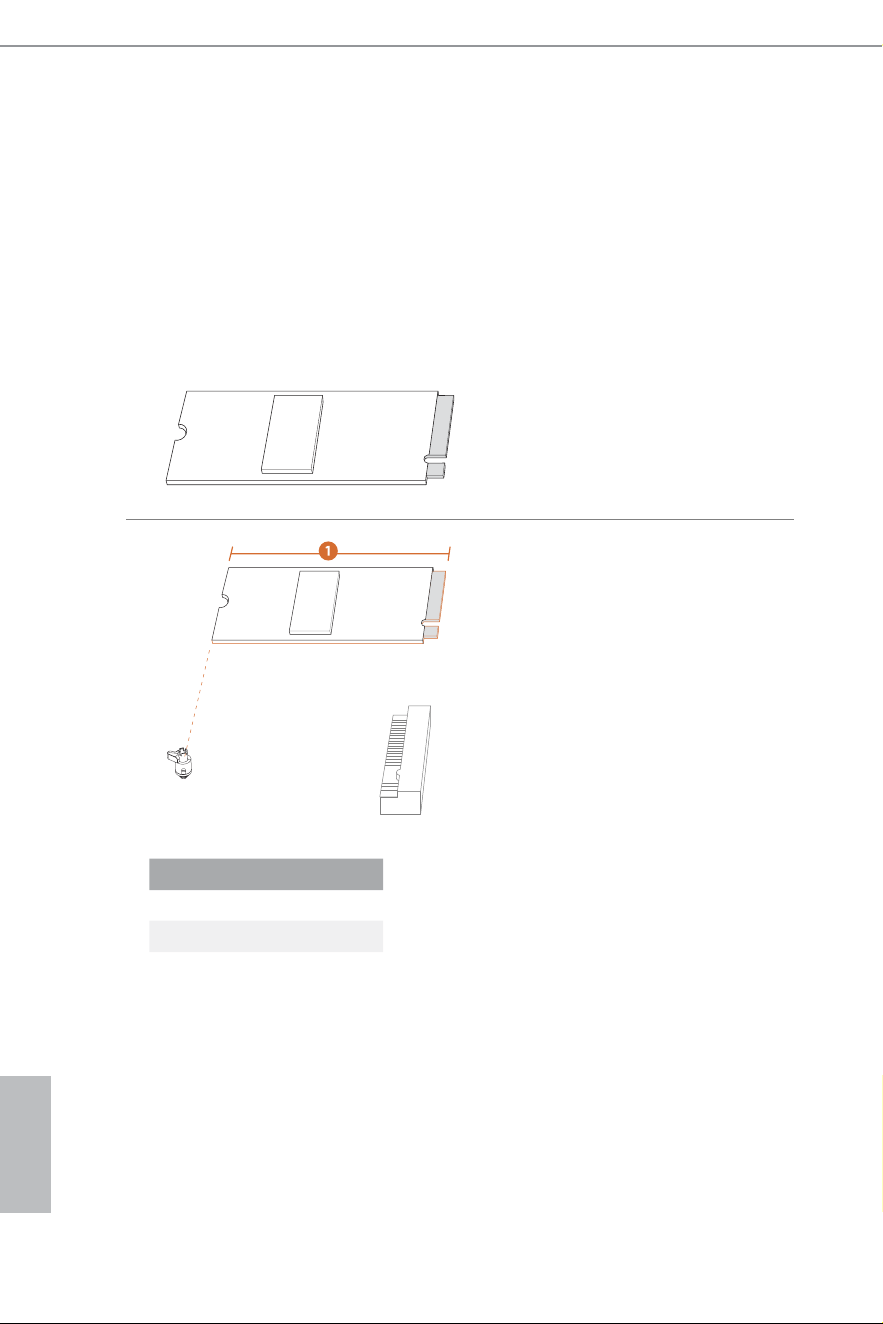
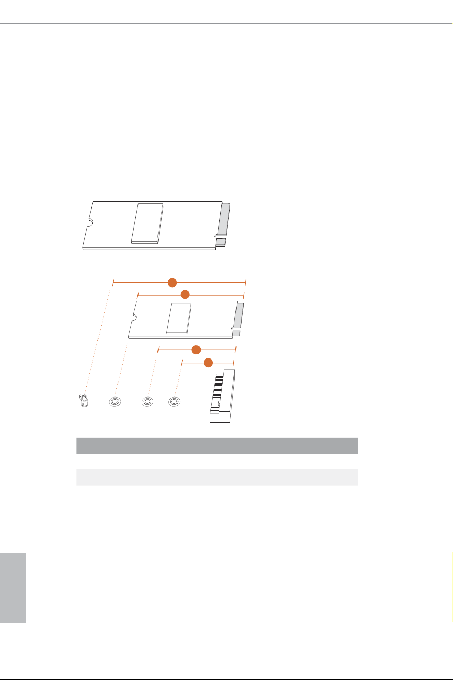
2.15 M.2 SSD Installation Guide (M2_1)
he M.2 is a small size and versatile card edge connector that aims to replace mPCIe and
mSATA. he
Blazing M.2 Socket (M2_1, Key M) supports type 2280 PCIe Gen5x4 (128 Gb/s)
mode.
Installing the M.2 SSD
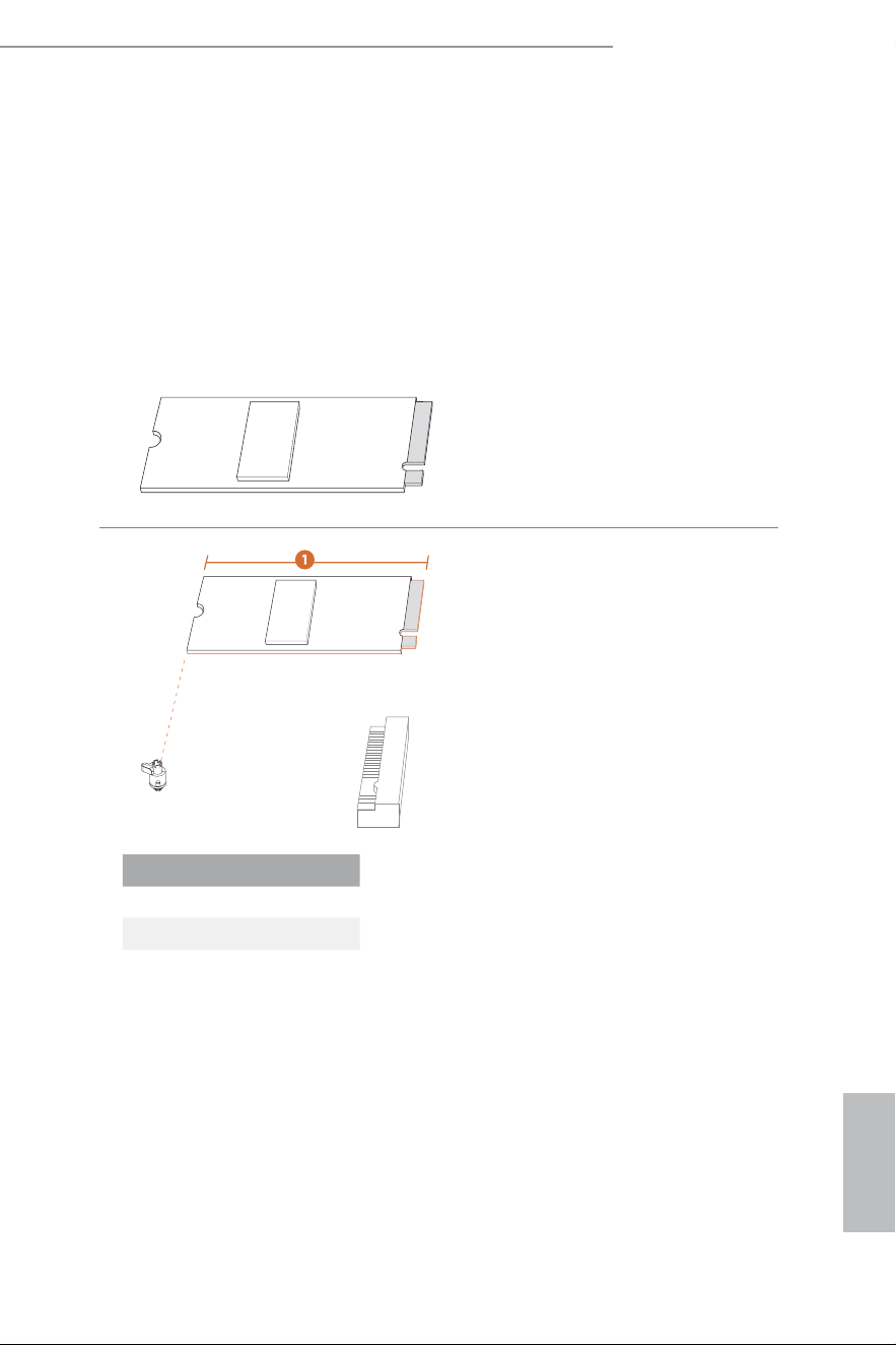
Step 1
Prepare a M.2 SSD.
Step 2
Depending on the PCB type and
length of your M.2 SSD, ind the
corresponding nut location to be
used.
No. 1
Nut Location A
PCB Length 8cm
Module Type Type 2280
A
English
51
Z890 Steel Legend WiFi
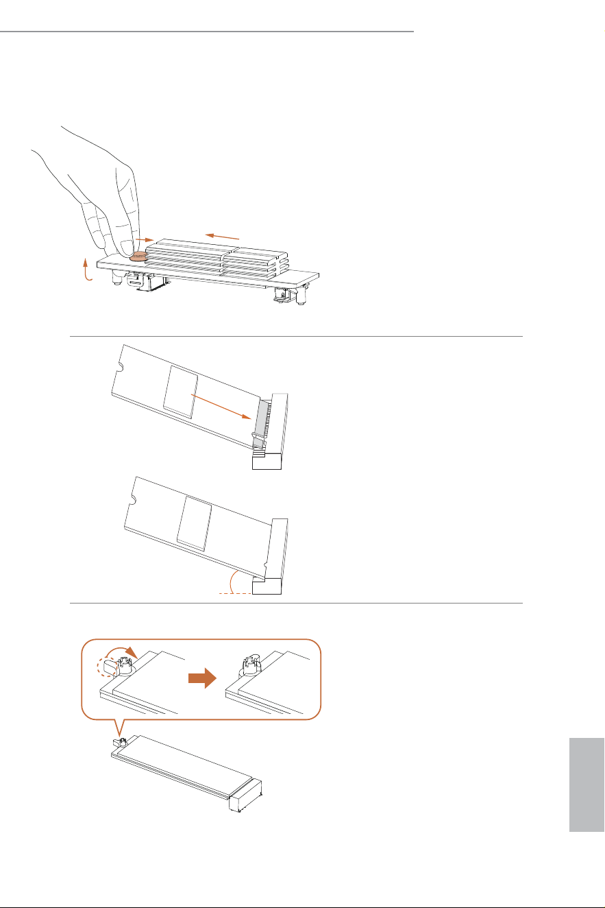
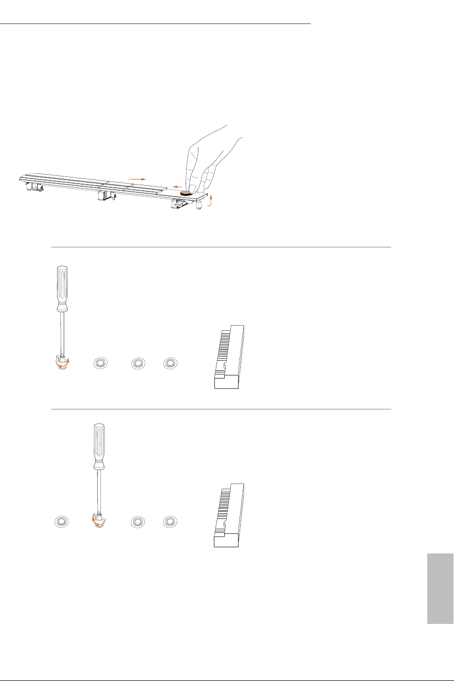
Step 3
Push the button on the M.2 heatsink
in the direction shown (A). hen lit
up the heatsink (B) and move it in
the direction shown (C).
*Please remove the protective ilms
on the bottom side of the M.2
heatsink before you install a M.2
SSD.
20
o
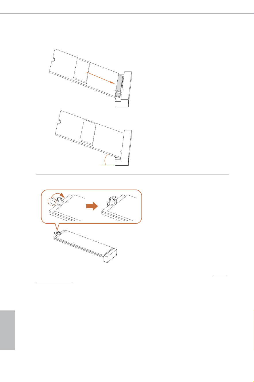
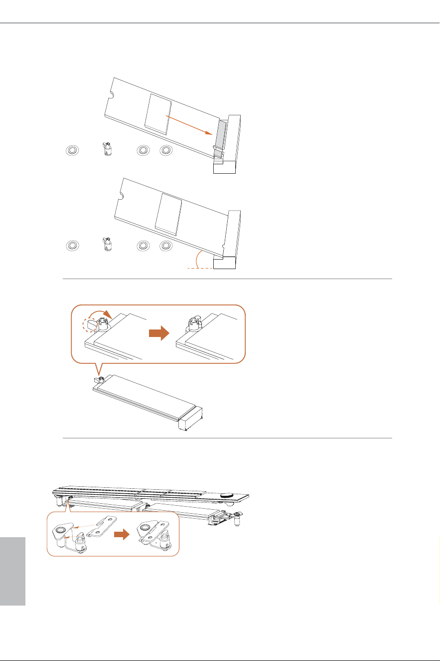
Step 4
Align and gently insert the M.2 SSD
into the M.2 slot. Please be aware
that the M.2 SSD only its in one
orientation.
Step 5
Ensure that the notch at the end of
the M.2 SSD aligns with the nut.
hen secure the M.2 SSD by turning
the nut lock clockwise to its locked
position.
A
B
C
English
52
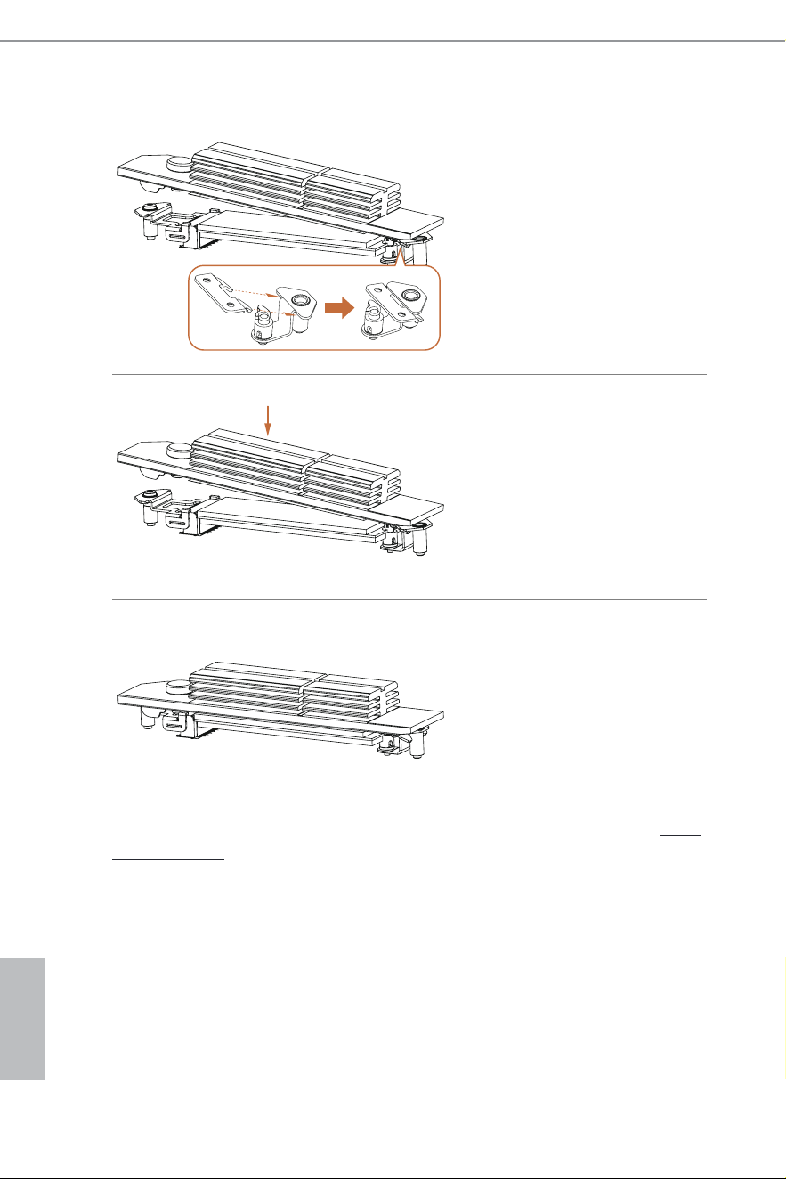
Step 6
Hook the tab of the M.2 heatsink back
onto the standof.
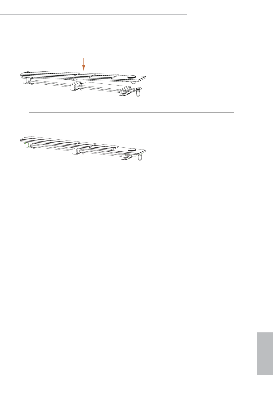
Step 7
Press the M.2 heatsink down into
place.
*Be sure not to press down the button
on the M.2 heatsink.
Step 8
Complete.
For the latest updates of M.2 SSD support list, please visit our website for details: http://
www.asrock.com
English
53
Z890 Steel Legend WiFi
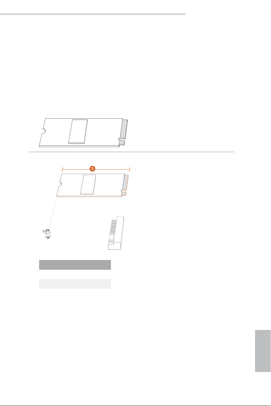
2.16 M.2 SSD Installation Guide (M2_2)
he M.2 is a small size and versatile card edge connector that aims to replace mPCIe and
mSATA. he
Hyper M.2 Socket (M2_2 , Key M) supports type 2280 PCIe Gen4x4 (64 Gb/s)
mode.
Installing the M.2 SSD
Step 1
Prepare a M.2 SSD.
Step 2
Depending on the PCB type and
length of your M.2 SSD, ind the
corresponding nut location to be
used.
No. 1
Nut Location A
PCB Length 8cm
Modu le Type Ty pe 2280
A
English
54
Step 3
Align and gently insert the M.2 SSD
into the M.2 slot. Please be aware
that the M.2 SSD only its in one
orientation.
Step 4
Ensure that the notch at the end of
the M.2 SSD aligns with the nut.
hen secure the M.2 SSD by turning
the nut lock clockwise to its locked
position.
20
o
For the latest updates of M.2 SSD support list, please visit our website for details: http://
www.asrock.com
English
55
Z890 Steel Legend WiFi
2.17 M.2 SSD Installation Guide (M2_3)
he M.2 is a small size and versatile card edge connector that aims to replace mPCIe and
mSATA. he
Hyper M.2 Socket (M2_3 , Key M) supports type 2280 SATA3 6.0 Gb/s &
PCIe Gen4x4 (64 Gb/s) modes.
Installing the M.2 SSD
Step 1
Prepare a M.2 SSD.
Step 2
Depending on the PCB type and
length of your M.2 SSD, ind the
corresponding nut location to be
used.
No. 1
Nut Location A
PCB Length 8cm
Module Type Type 2280
A
English
56
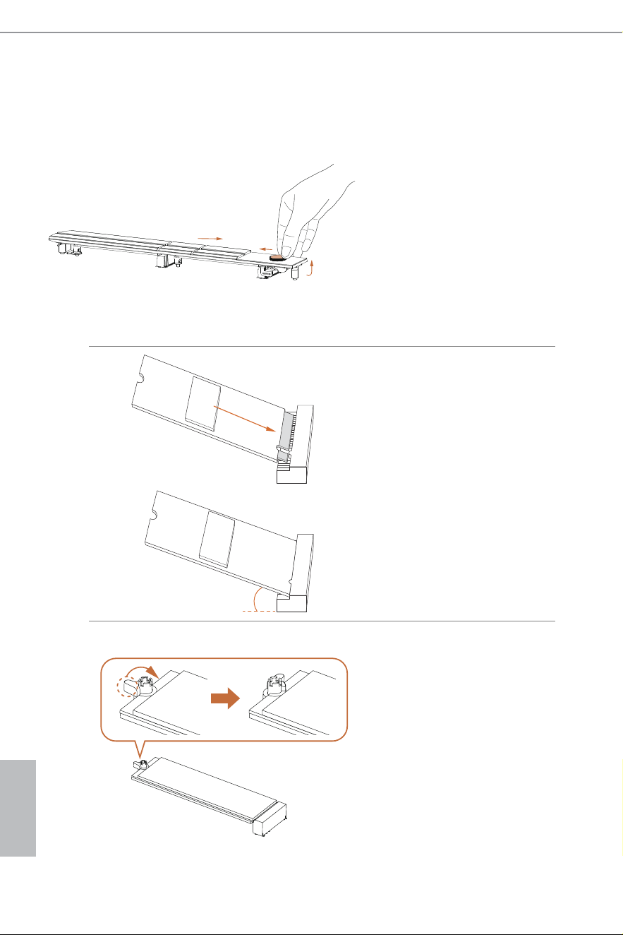
Step 3
Push the button on the M.2 heatsink
in the direction shown (A). hen lit
up the heatsink (B) and move it in
the direction shown (C).
*Please remove the protective ilms
on the bottom side of the M.2
heatsink before you install a M.2
SSD.
20
o
Step 4
Align and gently insert the M.2 SSD
into the M.2 slot. Please be aware
that the M.2 SSD only its in one
orientation.
Step 5
Ensure that the notch at the end of
the M.2 SSD aligns with the nut.
hen secure the M.2 SSD by turning
the nut lock clockwise to its locked
position.
A
B
C
English
57
Z890 Steel Legend WiFi
Step 6
Hook the tab of the M.2 heatsink back
onto the standof.
Step 7
Press the M.2 heatsink down into
place.
*Be sure not to press down the button
on the M.2 heatsink.
Step 8
Complete.
For the latest updates of M.2 SSD support list, please visit our website for details: http://
www.asrock.com
English
58
2.18 M.2 SSD Installation Guide (M2_4)
he M.2 is a small size and versatile card edge connector that aims to replace mPCIe and
mSATA. he
Hyper M.2 Socket (M2_4 , Key M) supports 2230/2242/2260/2280 PCIe
Gen4x4 (64 Gb/s) mode.
Installing the M.2 SSD
Step 1
Prepare a M.2 SSD.
Step 2
Depending on the PCB type and
length of your M.2 SSD, ind the
corresponding nut location to be
used.
3
2
4
BCD
A
1
No. 1 2 3 4
Nut Location A B C D
PCB Length 3cm 4.2cm 6cm 8cm
Modu le Type Type 2230 Type 2242 Type 2260 Type 2280
English
59
Z890 Steel Legend WiFi
Step 3
Push the button on the M.2 heatsink
in the direction shown (A). hen lit
up the heatsink (B) and move it in
the direction shown (C).
*Please remove the protective ilms
on the bottom side of the M.2
heatsink before you install a M.2
SSD.
BCD
A
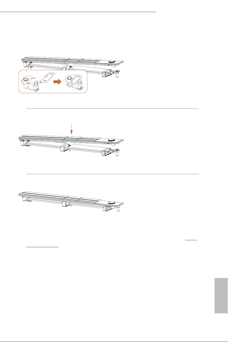
Step 4
Use a screwsriver to remove the
standof.
Skip Step 4 if your M.2 SSD is Type
2280.
BCD
A
Step 5
Peel of the yellow protective ilm
on the nut to be used. Tighten
the standof into the desired nut
location on the motherboard with a
screwdriver.
Skip Step 5 if your M.2 SSD is Type
2280.
A
B
C
English
60
ABCD
A
BCD
20
o
Step 6
Align and gently insert the M.2 SSD
into the M.2 slot. Please be aware
that the M.2 SSD only its in one
orientation.
Step 7
Ensure that the notch at the end of
the M.2 SSD aligns with the nut.
hen secure the M.2 SSD by turning
the nut lock clockwise to its locked
position.
Skip Step 7 if your M.2 SSD is Type
2230/2242/2260.
Step 8
Hook the tab of the M.2 heatsink
back onto the standof.
English
61
Z890 Steel Legend WiFi
Step 9
Press the M.2 heatsink down into
place.
*Be sure not to press down the
button on the M.2 heatsink.
Step 10
Complete.
For the latest updates of M.2 SSDsupport list, please visit our website for details: http://
www.asrock.com

Version 1.0
Published August 2024
Copyright©2024 ASRock INC. All rights reserved.
Copyright Notice:
No part of this documentation may be reproduced, transcribed, transmitted, or
translated in any language, in any form or by any means, except duplication of
documentation by the purchaser for backup purpose, without written consent of
ASRock Inc.
Products and corporate names appearing in this documentation may or may not
be registered trademarks or copyrights of their respective companies, and are used
only for identiication or explanation and to the owners’ beneit, without intent to
infringe.
Disclaimer:
Speciications and information contained in this documentation are furnished for
informational use only and subject to change without notice, and should not be
constructed as a commitment by ASRock. ASRock assumes no responsibility for
any errors or omissions that may appear in this documentation.
To the extent permitted by law, with respect to the contents of this documentation,
ASRock does not provide warranty of any kind, either expressed or implied,
including but not limited to the implied warranties or conditions of merchantability
or itness for a particular purpose. In no event shall ASRock, its directors, oicers,
employees, or agents be liable for any indirect, special, incidental, or consequential
damages (including damages for loss of proits, loss of business, loss of data,
interruption of business and the like), even if ASRock has been advised of the
possibility of such damages arising from any defect or error in the documentation
or product.

INTEL END USER SOFTWARE LICENSE AGREEMENT
IMPORTANT - READ BEFORE COPYING, INSTALLING OR USING.
LICENSE. Licensee has a license under Intel’s copyrights to reproduce Intel’s Sotware
only in its unmodiied and binary form, (with the accompanying documentation, the
“Sotware”) for Licensee’s personal use only, and not commercial use, in connection with
Intel-based products for which the Sotware has been provided, subject to the following
conditions:
(a) Licensee may not disclose, distribute or transfer any part of the Sotware, and You
agree to prevent unauthorized copying of the Sotware.
(b) Licensee may not reverse engineer, decompile, or disassemble the Sotware.
(c) Licensee may not sublicense the Sotware.
(d) he Sotware may contain the sotware and other intellectual property of third party
suppliers, some of which may be identiied in, and licensed in accordance with, an en-
closed license.txt ile or other text or ile.
(e) Intel has no obligation to provide any support, technical assistance or updates for the
Sotware.
OWNERSHIP OF SOFTWARE AND COPYRIGHTS. Title to all copies of the Sotware
remains with Intel or its licensors or suppliers. he Sotware is copyrighted and protected
by the laws of the United States and other countries, and international treaty provisions.
Licensee may not remove any copyright notices from the Sotware. Except as otherwise
expressly provided above, Intel grants no express or implied right under Intel patents,
copyrights, trademarks, or other intellectual property rights. Transfer of the license ter-
minates Licensee’s right to use the Sotware.
DISCLAIMER OF WARRANTY. he Sotware is provided “AS IS” without warranty of
any kind, EITHER EXPRESS OR IMPLIED, INCLUDING WITHOUT LIMITATION,
WARRANTIES OF MERCHANTABILITY OR FITNESS FOR ANY PARTICULAR PUR-
POSE.
LIMITATION OF LIABILITY. NEITHER INTEL NOR ITS LICENSORS OR SUPPLIERS
WILL BE LIABLE FOR ANY LOSS OF PROFITS, LOSS OF USE, INTERRUPTION OF
BUSINESS, OR INDIRECT, SPECIAL, INCIDENTAL, OR CONSEQUENTIAL DAMAG-
ES OF ANY KIND WHETHER UNDER THIS AGREEMENT OR OTHERWISE, EVEN
IF INTEL HAS BEEN ADVISED OF THE POSSIBILITY OF SUCH DAMAGES.
LICENSE TO USE COMMENTS AND SUGGESTIONS. his Agreement does NOT
obligate Licensee to provide Intel with comments or suggestions regarding the Sotware.
However, if Licensee provides Intel with comments or suggestions for the modiication,
correction, improvement or enhancement of (a) the Sotware or (b) Intel products or pro-
cesses that work with the Sotware, Licensee grants to Intel a non-exclusive, worldwide,
perpetual, irrevocable, transferable, royalty-free license, with the right to sublicense,
under Licensee’s intellectual property rights, to incorporate or otherwise utilize those
comments and suggestions.
TERMINATION OF THIS LICENSE. Intel or the sublicensor may terminate this license
at any time if Licensee is in breach of any of its terms or conditions. Upon termination,
Licensee will immediately destroy or return to Intel all copies of the Sotware.
THIRD PARTY BENEFICIARY. Intel is an intended beneiciary of the End User License
Agreement and has the right to enforce all of its terms.

U.S. GOVERNMENT RESTRICTED RIGHTS. he Sotware is a commercial item (as
deined in 48 C.F.R. 2.101) consisting of commercial computer sotware and commercial
computer sotware documentation (as those terms are used in 48 C.F.R. 12.212), consistent
with 48 C.F.R. 12.212 and 48 C.F.R 227.7202-1 through 227.7202-4. You will not provide
the Sotware to the U.S. Government. Contractor or Manufacturer is Intel Corporation,
2200 Mission College Blvd., Santa Clara, CA 95054.
EXPORT LAWS. Licensee agrees that neither Licensee nor Licensee’s subsidiaries will
export/re-export the Sotware, directly or indirectly, to any country for which the U.S.
Department of Commerce or any other agency or department of the U.S. Government
or the foreign government from where it is shipping requires an export license, or other
governmental approval, without irst obtaining any such required license or approval. In
the event the Sotware is exported from the U.S.A. or re-exported from a foreign destina-
tion by Licensee, Licensee will ensure that the distribution and export/re-export or import
of the Sotware complies with all laws, regulations, orders, or other restrictions of the U.S.
Export Administration Regulations and the appropriate foreign government.
APPLICABLE LAWS. his Agreement and any dispute arising out of or relating to it will
be governed by the laws of the U.S.A. and Delaware, without regard to conlict of laws
principles. he Parties to this Agreement exclude the application of the United Nations
Convention on Contracts for the International Sale of Goods (1980). he state and federal
courts sitting in Delaware, U.S.A. will have exclusive jurisdiction over any dispute aris-
ing out of or relating to this Agreement. he Parties consent to personal jurisdiction and
venue in those courts. A Party that obtains a judgment against the other Party in the
courts identiied in this section may enforce that judgment in any court that has jurisdic-
tion over the Parties.
Licensee’s speciic rights may vary from country to country.

FCC Compliance Statement
his device complies with Part 15 of the FCC Rules. Operation is subject to the following
two conditions:
(1) this device may not cause harmful interference, and
(2) this device must accept any interference received, including interference that
may cause undesired operation.
his equipment has been tested and found to comply with the limits for a Class B digital
device, pursuant to part 15 of the FCC Rules. hese limits are designed to provide
reasonable protection against harmful interference in a residential installation. his
equipment generates, uses and can radiate radio frequency energy and, if not installed
and used in accordance with the instructions, may cause harmful interference to radio
communications. However, there is no guarantee that interference will not occur in a
particular installation. If this equipment does cause harmful interference to radio or
television reception, which can be determined by turning the equipment of and on, the
user is encouraged to try to correct the interference by one or more of the following
measures:
- Reorient or relocate the receiving antenna.
- Increase the separation between the equipment and receiver.
- Connect the equipment into an outlet on a circuit diferent from that to which the
receiver is connected.
- Consult the dealer or an experienced radio/TV technician for help.
Button Battery Safety Notice
- Remove and immediately recycle or dispose of used batteries according to local
regulations and keep away from children. Do NOT dispose of batteries in household
trash or incinerate.
- Even used batteries may cause severe injury or death.
- Call a local poison control center for treatment information.
- Battery type: CR2032
- Battery voltage: 3V
- Non-rechargeable batteries are not to be recharged.
- Do not force discharge, recharge, disassemble, heat above (manufacturer's speciied
temperature rating) or incinerate. Doing so may result in injury due to venting, leakage
or explosion resulting in chemical burns.
- his product contains an irreplaceable battery.
- his icon indicates that a swallowed button battery can cause serious injury or death.
Please keep batteries out of sight or reach of children.
WARNING
• INGESTION HAZARD: This product contains a button cell or
coin battery.
• DEATH or serious injury can occur if ingested.
• A swallowed button cell or coin battery can cause Internal
Chemical Burns in as little as 2 hours.
• KEEP new and used batteries OUT OF REACH of CHILDREN
• Seek immediate medical attention if a battery is suspected to
be swallowed or inserted inside any part of the body.

CALIFORNIA, USA ONLY
he Lithium battery adopted on this motherboard contains Perchlorate, a toxic substance
controlled in Perchlorate Best Management Practices (BMP) regulations passed by the
California Legislature. When you discard the Lithium battery in California, USA, please
follow the related regulations in advance.
“Perchlorate Material-special handling may apply, see www.dtsc.ca.gov/hazardouswaste/
perchlorate”
CALIFORNIA, USA ONLY
WARNING: Cancer and Reproductive Harm
www.P65Warnings.ca.gov
CE Conformity
ASRock INC. hereby declares that this device is in compliance with the essential require-
ments and other relevant provisions of related Directives. Full text of EU declaration of
conformity is available at: http://www.asrock.com
ASRock follows the green design concept to design and manufacture our products, and
makes sure that each stage of the product life cycle of ASRock product is in line with
global environmental regulations. In addition, ASRock disclose the relevant information
based on regulation requirements.
Please refer to https://www.asrock.com/general/about.asp?cat=Responsibility for informa-
tion disclosure based on regulation requirements ASRock is complied with.
UKCA Conformity
ASRock INC. hereby declares that this device is in compliance with the essential require-
ments and other relevant provisions of related UKCA Directives. Full text of UKCA
declaration of conformity is available at: http://www.asrock.com
Consumer Limited Warranty - Australia
Our goods come with guarantees that cannot be excluded under the Australian Consumer
Law. You are entitled to a replacement or refund for a major failure and compensation for
any other reasonably foreseeable loss or damage caused by our goods. You are also entitled
to have the goods repaired or replaced if the goods fail to be of acceptable quality and the
failure does not amount to a major failure. If you require assistance please call ASRock Tel
: +886-2-28965588 ext.123 (Standard International call charges apply)
WARNING
THIS PRODUCT CONTAINS A BUTTOON BATTERY
If swallowed, a button battery can cause serious injury or death.
Please keep batteries out of sight or reach of children.
Proper Disposal
DO NOT throw the motherboard in municipal waste. his product has been
designed to enable proper reuse of parts and recycling. his symbol of the
crossed out wheeled bin indicates that the product (electrical and electronic
equipment) should not be placed in municipal waste. Check local regulations
for disposal of electronic products.
Class B ITE
この装置は、クラスB情報技術装置です。この装置は、家庭環境で使用することを目的と
していますが、この装置がラジオやテレビジョン受信機に近接して使用されると、受信障
害を引き起こすことがあります。取扱説明書に従って正しい取り扱いをして下さい。
Trademark Information
he terms HDMI® and HDMI High-Deinition Multimedia Interface, and the HDMI
logo are trademarks or registered trademarks of HDMI Licensing LLC in the United
States and other countries.
European Community Radio Equipment Directive Compliance
Statement
his device complies with directive 2014/53/EU issued by the Commision of the
European Community. his equipment complies with EU radiation exposure limits
set forth for an uncontrolled environment.
his equipment should be installed and operated with minimum distance 20cm
between the radiator & your body.
Operations in the 5.15-5.35/6GHz band are restricted to indoor usage only.
Radio Frequency Bands and Maximum Power Levels
• Features : Wi-Fi 6E, BT, Wi-Fi 7
• Frequency Range : 2.4 GHz: 2400-2485MHz; 5 GHz: 5150-5350MHz, 5470-5725MHz,
5725-5850MHz; 6 GHz: 5955-6415MHz
• Max Power Level : 2.4 GHz: 20dBm; 5 GHz: 23dBm; 6 GHz: 23dBm
Compliance Statement of Innovation, Science and Economic
Development Canada (ISED)
his device complies with with Innovation, Science and Economic Development
Canada’s licence-exempt RSS(s). Operation is subject to the following two
conditions: (1) this device may not cause interference, and (2) this device must
accept any interference, including interference that may cause undesired operation
of the device. Operation in the band 5150-5250 MHz is only for indoor use to
reduce the potential for harmful interference to co-channel mobile satellite
systems. CAN ICES-003(B)/NMB-003(B)
NCC
無線設備警告聲明
經型式認證合格之低功率射頻電機,非經許可,公司、商號或使用者均不得擅自變更頻率、
加大功率或變更原設計之特性及功能。 低功率射頻電機之使用不得影響飛航安全及干擾合
法通信;經發現有干擾現象時,應立即停用,並改善至無干擾時方得繼續使用。前項合法
通信,指依電信法規定作業之無線電通信。低功率射頻電機須忍受合法通信或工業、科學
及醫療用電波輻射性電機設備之干擾。