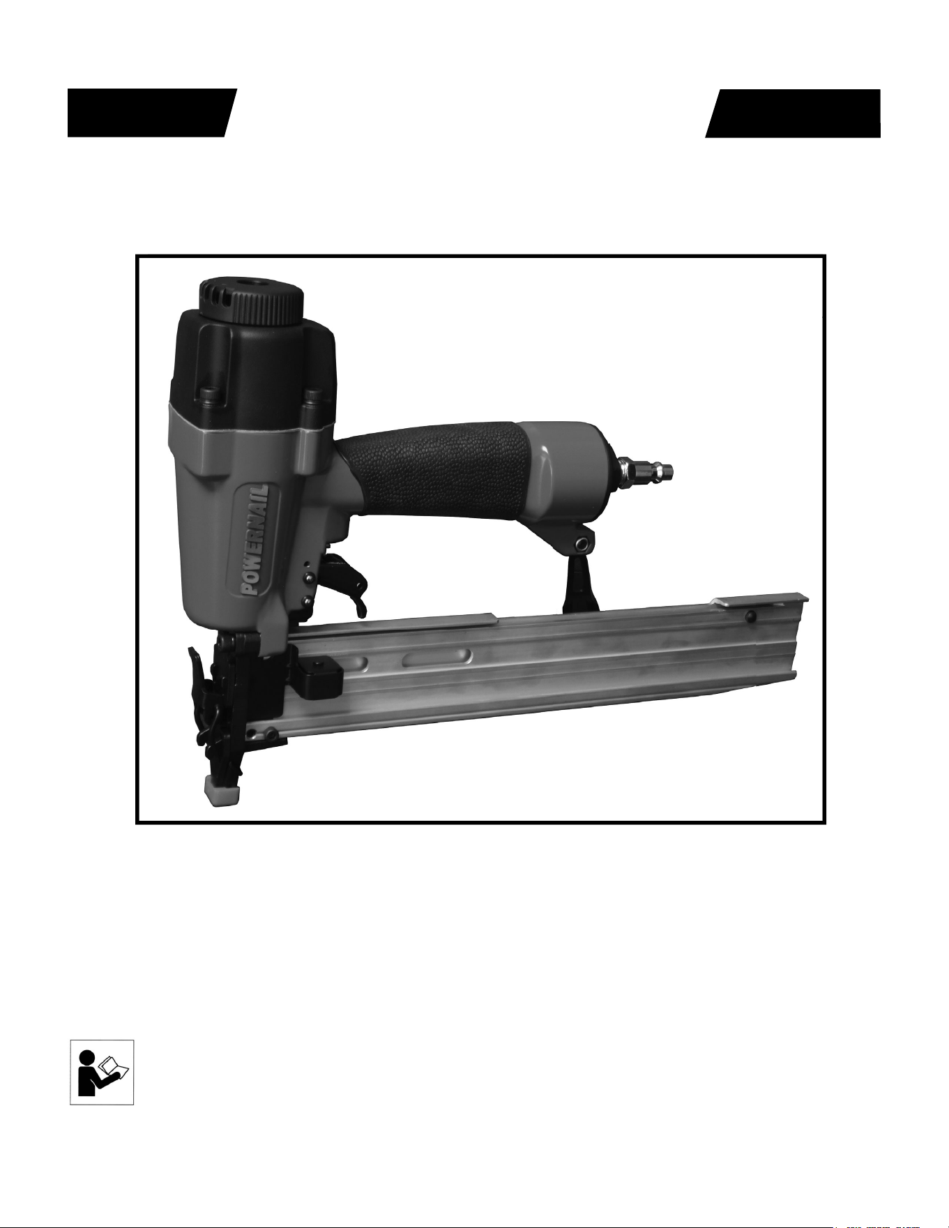
Model 1890U PowerStapler™
POWERNAIL
®
CO.
REV 15.08.07
WARNING
OPERATION AND MAINTENANCE MANUAL
MANUAL DE OPERACION Y DE MANTENIMIENTO
MANUEL D’INSTRUCTIONS ET D’ENTRETIEN
Read this manual before you use this Powernailer®. Follow all safety warnings and
instructions. If you are uncertain about the operation of the nailer, call us directly
at 1-800-323-1653 for assistance or contact the closest Powernail Dealer for help.
Please retain this information for future reference.

2
The 1890U PowerStapler® is a trigger-pull stapler designed to bring Powernail
quality and fl ooring expertise to a pneumatic stapler. The 1890U is designed for
use with 1/4” crown, 18 GA staples from 7/8” to 1-1/2” in length.
INTRODUCTION
INDEX
LIMITED WARRANTY
POWERNAIL® Company, Inc. warrants to its customer, and to the fi rst end-use purchaser
of POWERNAIL 1890U PowerStapler purchased from an authorized POWERNAIL
distributor, that each serialized manufactured 1890U PowerStapler by POWERNAIL®,
for a period of 12 months from the date of purchase; shall be free of defects in materials and
workmanship and will meet POWERNAIL’S specifi cations in eff ect at the time of product
shipment. POWERNAIL will repair or replace, at its option, any 1890U PowerStapler that
does not conform to this warranty. Claims must be made no later than fi fteen (15) days after
the end of the warranty period. POWERNAIL will perform all repair or replacements itself
or through its authorized contractors. POWERNAIL is not responsible for shipping, labor
or other direct or indirect costs. Damage caused by abuse, misuse, unusual or excessive
wear is excluded. Repair or modifi cation of the Products by unauthorized parties will
void this warranty. The customer is responsible for returning Products to POWERNAIL
for verifi cation of nonconformance. Warranties for Products not manufactured by
POWERNAIL are limited to warranties provided to POWERNAIL by the manufacturer of
such product that are assignable to customer.
THESE WARRANTIES AND REMEDIES ARE EXCLUSIVE OF ALL OTHERS,
EXPRESS OR IMPLIED. THE WARRANTIES OF MERCHANTABILITY AND
FITNESS FOR PURPOSE ARE EXPRESSLY EXCLUDED. IN NO EVENT SHALL
POWERNAIL’S LIABILITY FOR A WARRANTY CLAIM EXCEED THE PRICE PAID
TO POWERNAIL FOR THE NONCONFORMING PRODUCT, REGARDLESS OF THE
FORM OR BASIS OF THE CLAIM OR CAUSE OF ACTION.
Index..................................... 2
Warranty............................... 2
Safety Instructions................ 3
Operating the tool................. 4-6
Air Supply............................. 5
Loading fasteners................. 6
Clearing a jam...................... 7
Safety Labels........................ 7
Troubleshooting Chart.......... 9
Parts List........................ 10
Schematic........................ 11
Phone Support..................... 12
Web Site.............................. 12
Powernail Company Info..... 12
SAFETY INSTRUCTIONS
3
When operating this Nailer, the operator and others in the work area should ALWAYS wear approved
SAFETY GLASSES, with front and side eye protection. Eye protection will help guard against fl ying
nails and debris, which could cause severe eye injury.
EAR PROTECTION should be used to prevent hearing damage when there are high noise levels
in the work area. ALWAYS use ear plugs with a noise reduction rated at 29 db or higher at a
construction site.
Noise characteristic values in accordance with ENxx1:
A-weighted single-event sound pressure level at operator’s position: LPA, ls94dBA
A-weighted single sound pressure level:LpA,ls,lm89dBA
Vibration characteristic values in accordance with ISO 8662, PART II
Weighted root mean square acceleration 3.2m/s²
Always DISCONNECT THE AIR SUPPLY before making any adjustments, repairing, clearing jams or when
the Nailer is not in use. Do not use on scaff olding or ladders and disconnect nailer from air supply when
transporting
between installation areas.
Never attach the female end of a quick disconnect to the Nailer. This will trap air inside the Nailer and permit it
to be discharged. Only the unrestricted male connection should be attached to the Nailer.
Nailer requires an air source that can continuously deliver 70 to 100 psi at 3-1/2 cubic feet of air per minute
for operation.
Normal air pressure should not exceed 100 psi or damage to the Nailer and seals may occur. Excess air
pressure can cause the Nailer to explode.
To prevent fi re or explosion, use only regulated compressed air—do not use bottled gases of any kind (no
oxygen or combustible gasses) to power this Nailer.
Nailer is intended for use installing wood fl ooring and is not to be used for purposes not specifi ed in the
operations manual.
Do not use any nails other than Powernail® Powercleats which are 20 gage L-cleat nails specifi cally designed
for use in any 20 gage Powernailer. Powercleat nails are available in lengths of 1” and 1-1/4”. Contact your
Powernail Dealer for the correct Powercleats for the Model 2000.
Use only Powernail replacement parts in the repair or maintenance of this nailer. Parts or repair services are
available from the manufacturer or from agents authorized by the manufacturer. Repairs should be carried out
only by trained service personel in the fi eld of fastener driving tools who will observe proper safety controls
while performing maintenance. Service personel should be qualifi ed to assess the safe working condition of
fastener driving tools.
Always make sure Nailer is empty of nails before connecting air hose, so as to prevent any accidental
discharge from occurring. ONLY CONNECT AIR TO AN UNLOADED NAILER.
Do not depress the trigger when loading. If the fasteners are jammed, disconnect the tool from the air supply
before you remove the jammed nails.
Never place any part of the body in the discharge path of the Nailer when air is connected to the
Nailer. Never point the tool at yourself or others, even if the tool is not loaded. For safety, keep out
of reach of children. Never leave the Nailer unattended while it is connected to an air supply.
Do not fi re into hard materials or attempt to use on hard or brittle material such as concrete, steel
or tile. Before using this tool, carefully check that all parts are working correctly. Do not use the tool if it is not
operating correctly, check for causes and adjust as necessary for proper operation. When not in use, the tool
should be cleaned, fully assembled and then stored in a dry location. This will extend the life of the tool and
reduce any oxidation.
4
OPERATION
The Model 1890U is designed for use with 18 gauge, 1/4” crown
staples in lengths from 7/8” to 1-1/2”.
APPLICATIONS: Carpet and Carpet Pad Installation,
Home Insulation Installation
*Only use tool for its intended purposes. Drive fasteners into work
surfaces only; never into materials too hard to penetrate.
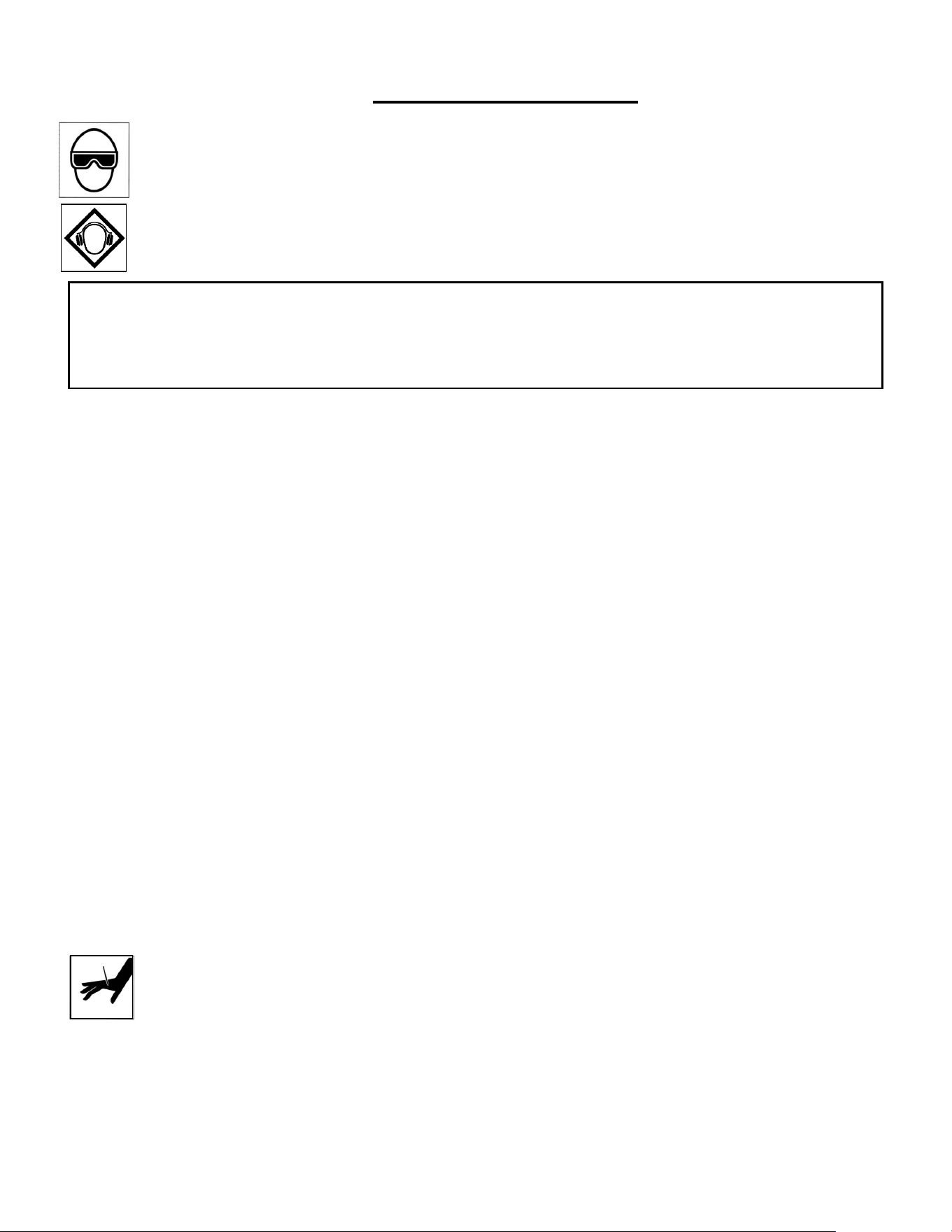
Single-fi re Procedure
1. Set the nailer to the work surface with the nose pressed down
to release the safety.
2. Squeeze the trigger once for single-fi re operation.
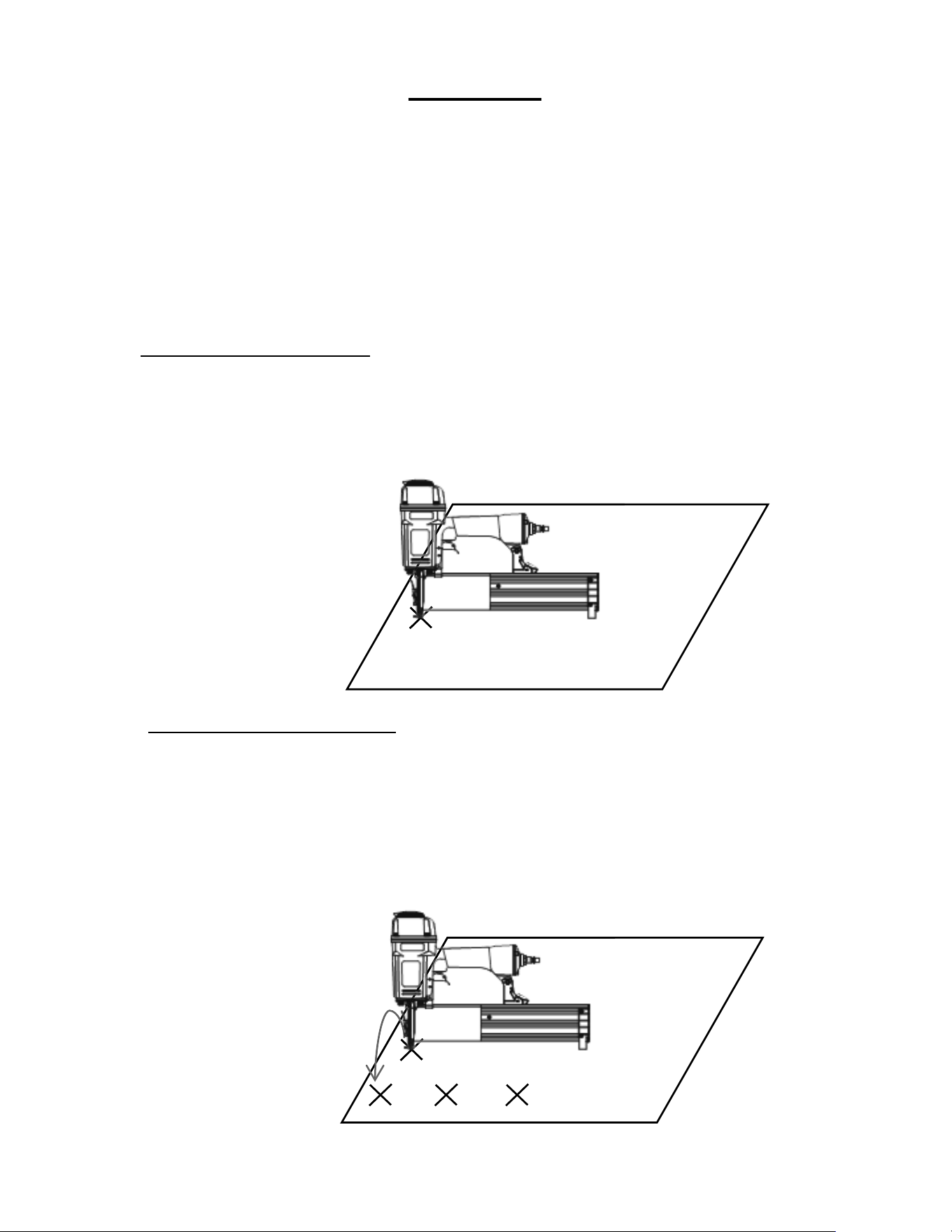
“Bump-fi re” Procedure
1. First squeeze and hold the trigger in the fi re position.
2. Then push nailer-nose to the surface in the exact spot you wish
to nail. The nailer will fi re each time the nailer nose is pushed to
the work surface when you hold the trigger in the fi re position.
5
OPERATION, continued...
Before using this tool, carefully check that all parts are working correctly. Do not use
the tool if it is not operating correctly, check for causes and adjust as necessary for
proper operation.
Secure your work. Use clamps or a vise to hold your work project in place. It is safer
than using your hands and it frees both hands to operate tool.
Do not drive fasteners on top of other fasteners or with tool at too steep of an angle; the
fasteners may ricochet and injure someone.
Do not drive fasteners too close to the edge of the work surface. The work piece is
likely to split and the fastener could fl y free or ricochet and injure someone.
Do not fi re into hard materials or attempt to use on hard or brittle materials such as
concrete, steel or tile.
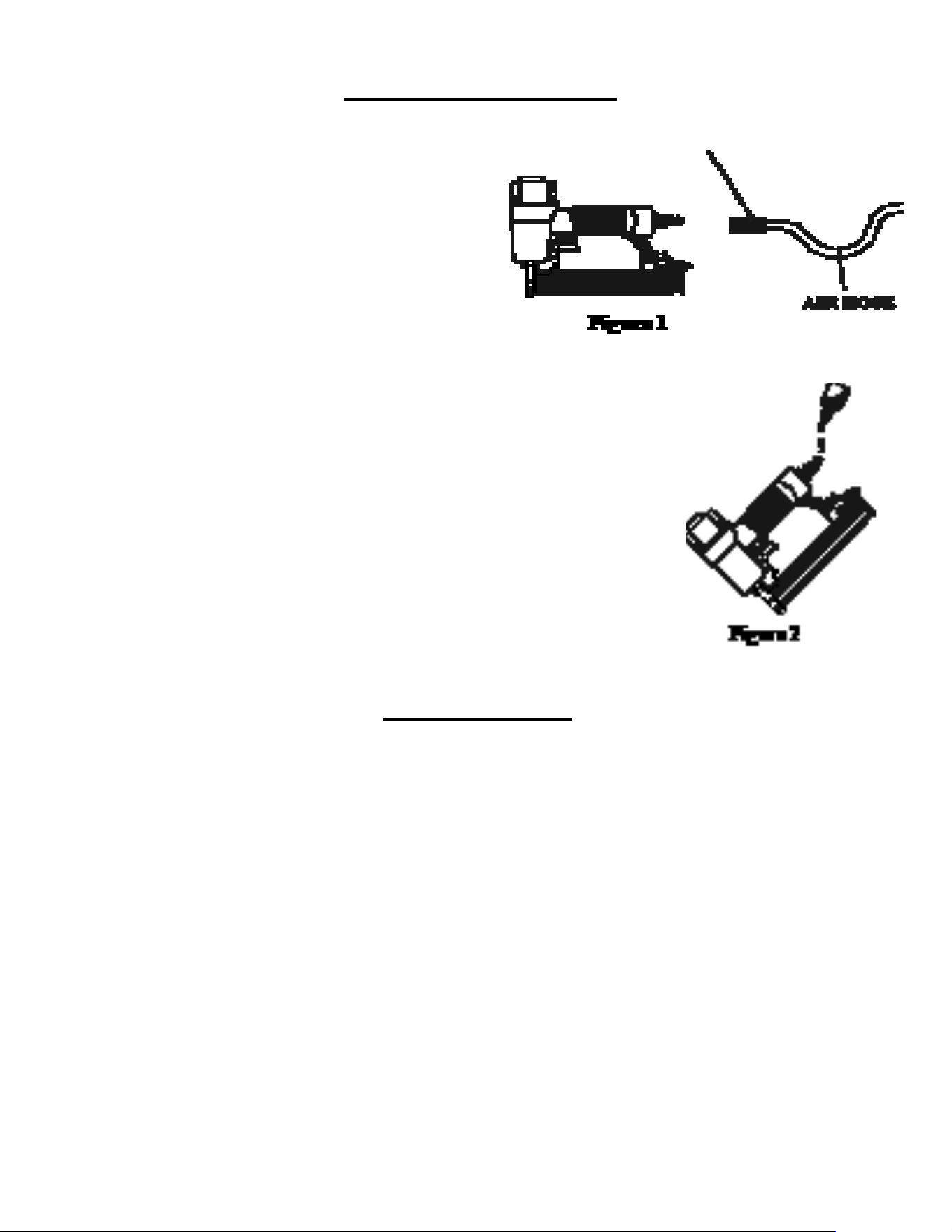
CONNECTING THE TOOL TO AN AIR SUPPLY
Your air tool is fully assembled when you
receive it. Before using it, attach the air line
and desired air system accessories. Be
sure the air hose is depressurized when
installing or removing adapters to the air
line. To prevent misfi re, do not connect air to
a loaded nailer.
1. An automatic airline oilier is recommended but oil may be added
manually before every operation or after about 1 hour of continuous
use.
2. Place two (2) drops of air-tool oil into the air plug at the rear of the
nailer. If you are using an automatic in-line oiler, check and add oil if
necessary.
3. Turn your compressor on and set the compressors pressure
regulator to the proper pressure for the size and type of fastener
being used. Normal operating pressure should be adjusted between
70-100 psi based on fastener and wood being used.
4. Connect the tool to the air supply (Figure 2).
OPERATING TIPS
6
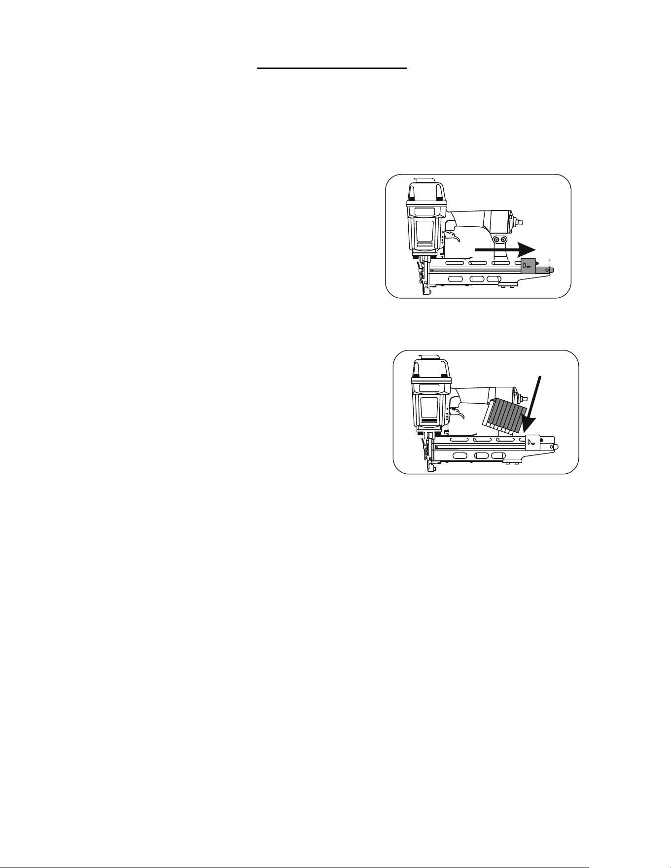
LOADING STAPLES
1. Disconnect air supply.
2. Pull back on staple pusher in
the magazine unit until it locks
over the spring loaded stopper.
3. Load a clip of staples over
the top of the staple channel.
4. Release the staple pusher from
the spring loaded stopper and
gently allow it to move forward to engage
the fasteners in the magazine.
5. Connect air supply to the tool.
7
NAILER SAFETY LABELS
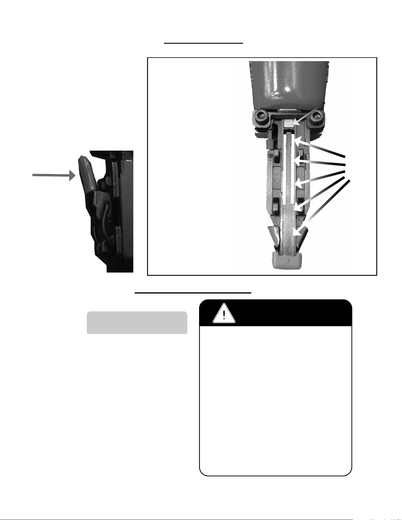
CLEARING JAMS
WARNING!
1. Read and understand operating manual
before using.
2. Operator and all the by-standers must wear
ANSI approved safety glasses, ear and head
protections.
3. Never use oxygen or other fl ammable gases.
Only choose clean dry regulated compressed
air below 100 PSI pressure.
4. Remove fi nger from trigger while not
operating.
5. Never trip over the hose. Make sure all
connections are tight.
6. Disconnect the tool from air supply before
clearing jams, serviceing, adjusting or during
non-operation.
7. Don’t point tool at people or animals while
operating.
Operating Pressure
70 - 100 psi
Driving Blade
1. Disconnect air supply.
2. Pull the release lever to
unlatch magazine cover
and slide it to the rear
3. Use the release lever to
remove the nose-cover
assmebly.
4. Inspect and clear
the driveblade path
of any material or
debris.
Drive
Blade
Path

8

PROBLEM POSSIBLE CAUSE SOLUTION
1
Air leaking at
Trigger valve area
1. Damaged O-rings in trigger valve housing 1. Replace O-rings and check the
operation of safety yoke mechanism
2
Air leaking between
housing and nose
1. Loose screws in housing 1. Tighten screws
3
Air leaking between
housing and cap
assembly
1. Loose screws
2. Damaged seal.
1. Tighten screws.
2. Replace seal.
4
Tool skips driving
fastner
1. Worn bumper.
2. Dirt in nose.
3. Dirt or damage prevents fasteners from
moving freely in magazine.
4. Inadequate air fl ow.
5. Worn O-ring on piston or lack of lubrication.
6 Damaged O-rings on trigger valve.
7. Air leaks.
8. Air leakage due to worn cap seal.
1. Replace bumper
2. Clean nose.
3. Clean magazine and inspect and repair
damage.
4. Check fi tting, hose and air pressure.
5. Replace O-rings and lubrication.
6. Replace O-rings.
7. Tighten screws and fi ttings.
8. Replace seal.
5
Weak drive
1. Tool not lubricated.
2. Broken spring in cap assembly.
3. Exhaust port in cap is blocked.
1. Lubrication.
2. Replace spring.
3.Clean or replace damaged internal
parts.
6
Tool jams
1. Worn or damaged nose.
2. Damaged driver.
3. Incorrect size of fastners.
4. Bent fasteners.
5. Magazine or nose screws are loose.
1. Replace nose.
2. Replace driver.
3. Use recommended fasteners.
4. Replace with new fasteners.
5. Tighten screws.
7
Tool does not fi re
1. Fasteners jammed in magazine or discharge
area.
2. Piston shaft is damaged.
3. Air pressure too low.
1. Inspect and clean magazine.
2. Replace piston shaft.
3. Check/increase air pressure.
Here are some common issues that may occur during use.
If the nailer is not working as it should, stop using the tool immediately and resolve the
issue before continuing.
9
TROUBLE SHOOTING CHART

10
ITEM DESCRIPTION Req PART #
2 UM HD Bolt 1 n/a
3 Flat Washer 1 n/a
4 Seal 1 n/a
5 Exhaust Cover 1 n/a
6 Cap 1 n/a
7 Seal 1 n/a
8 Spring 1 n/a
9 O-Ring 1 09-18U009
10 Head Valve 1 09-18U010
11 O-Ring 1 09-18U011
12 Cap Gasket 1 09-18U012
13 Hex Soc HD Bolt+SW 4 n/a
14 Drive Blade 1 n/a
14A Drive Blade Asm. w/O-Ring 1 09-18U014A
15 O-Ring 1 09-18U015
16 Collar 1 n/a
17 O-Ring 1 09-18U017
18 Cylinder 1 09-18U018
19 O-Ring 1 09-18U019
20 O-Ring 1 09-18U020
21 Bumper 1 09-18U021
22 Stepped Pin 1 n/a
23 Joint Guide 1 09-18U023
24 O-Ring 1 09-18U024
25 Body 1 n/a
26 Hex Soc HD Bolt 1 09-18U026
27 Lock Nut 1 09-18U027
28 O-Ring 1 n/a
29 Rear Cover 1 n/a
30 Air Plug 1 n/a
31 Trigger Valve Asm 1 n/a
32 Trigger Assembly 1 n/a
33 Trigger Spring 1 n/a
34 Guide Safety Lever 1 n/a
35 Safety 1 09-18U035
36 Rubber Safety Pad 1 09-18U036
ITEM DESCRIPTION Req PART #
37 Hex Soc HD Bolt+SW 09-18U037
38 Plate n/a
39 Anchor n/a
40 Gate 09-18U040
41 Locknut n/a
42 Fixed Magazine n/a
43 Hex Soc HD Bolt 09-18U043
44 Bracket n/a
45 E-Clip 09-18U045
46 DetentSpring 09-18U046
47 Stopper 09-18U047
48 Stepped Pin n/a
49 Pusher 09-18U049
50 E-Clip n/a
51 Pusher Spring 09-18U051
52 Roller n/a
53 Hex Soc HD Bolt 09-18U053
54 Rolled Pin n/a
55A Nose Cover Assembly 09-18U055A
56 Driver Guide Cover n/a
57 Latch n/a
58 Rolled Pin n/a
59 Rubber Release Pad 09-18U059
MODEL 1890U PARTS LIST
KEY: S=Sold Separately, n/a Not available separately, KIT=Sold as part of a Kit
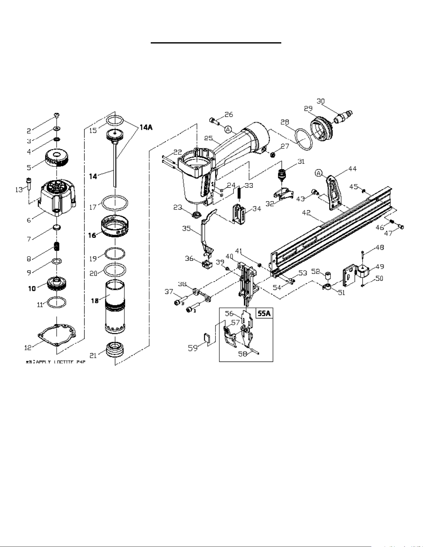
11
MODEL 1890U SCHEMATIC

POWERNAIL COMPANY, INC.
1020 Williams Road, Genoa City, WI 53128 US
Phone: 1-800-323-1653 or 262-292-5300
www.powernail.com
12
