

WARNING
GB
United
Kingdom
SAFETY, OPERATION
& MAINTENANCE MANUAL
A SIGNATURE CUT, TRUSTED FOR OVER 100 YEARS
WARNING: If incorrectly used this machine can cause severe injury. Those who use and maintain this machine must
be trained in its proper use, warned of its dangers and must read the entire manual before attempting to set up,
operate, adjust or service the machine.
10015205-A
RJL AGCD
Jacobsen GP400™ Ride on Greens Mower
CAT® - C0.7 Diesel
GP400 Diesel (CAT® - C0.7)
Series: DDE / Product code:USAD004E

© 2023 Textron Specialized Vehicles
This manual may not be reproduced in whole or in part without the express permission of Ransomes Jacobsen Ltd.
CALIFORNIA PROPOSITION 65
WARNING
The engine exhaust from this product contains
chemicals known to the State of California to cause
cancer, birth defects and other reproductive harm.
!

CONTENTS
SECTION 1 - FOREWORD
IMPORTANT ..................................................................... 3
PRODUCTION IDENTIFICATION..................................... 4
GUIDELINES FOR DISPOSAL SCRAP PRODUCTS....... 6
END OF SERVICE LIFE.................................................... 6
PARTS MANUAL............................................................... 7
KEY NUMBERS ................................................................ 7
SECTION 2 - SAFETY
HOW TO OPERATE SAFELY........................................... 9
SAFE OPERATION ........................................................... 9
PREPARATION................................................................. 9
OPERATION ................................................................... 10
ROPS AND CABIN.......................................................... 10
SAFE HANDLING OF FUELS ......................................... 11
MAINTENANCE AND STORAGE ................................... 11
WHEN YOU PUT THE MOWER ON TO TRAILER......... 12
IMPORTANT SAFETY NOTES ....................................... 13
SECTION 3 - SPECIFICATIONS
ENGINE SPECIFICATION .............................................. 16
DIMENSIONS & WEIGHTS............................................. 17
MACHINE SPECIFICATION ........................................... 18
VIBRATION LEVEL ......................................................... 19
NOISE LEVEL ................................................................. 20
SLOPES .......................................................................... 20
CUTTING UNIT SPECIFICATION................................... 21
CUTTING PERFORMANCE............................................ 22
RECOMMENDED LUBRICANTS................................... 22
ACCESSORIES............................................................... 22
SECTION 4 - DECALS
DECALS .......................................................................... 24
INSTRUCTION DECALS................................................. 26
SECTION 5 - CONTROLS
OPERATOR WORKSTATION ......................................... 28
INSTRUMENT PANEL..................................................... 29
STARTER KEY SWITCH ................................................ 30
THROTTLE CONTROL LEVER ...................................... 30
CUTTING UNIT SWITCH (PTO) ..................................... 30
JOYSTICK ...................................................................... 31
WORKING LIGHTS ......................................................... 31
ENGINE COOLANT TEMPERATURE ............................ 31
HOUR METER ............................................................... 31
BLOCKED HYDRAULIC FILTER WARNING LIGHT.......32
MULTIFUNCTION WARNING LIGHT..............................32
OIL PRESSURE WARNING LIGHT ................................32
MOW / TRANSPORT LEVER..........................................33
POWER OUTLET ............................................................33
HORN BUTTON...............................................................33
PARKING BRAKE............................................................34
TRACTION PEDAL..........................................................34
STEERING WHEEL.........................................................34
LIFT & LOWER RATE .....................................................35
FREE WHEEL.................................................................. 35
SECTION 6 - OPERATION
DAILY INSPECTION........................................................36
OPERATOR PRESENCE / SAFETY INTERLOCK ........ 36
OPERATING PROCEDURE............................................37
SETTING UP THE MACHINE..........................................39
MOUNTING THE CUTTING HEADS...............................40
REEL MOTOR MOUNTING.............................................41
CUTTING LIFT / LOWER RATE & SYNC ....................... 42
OPERATION OF THE MACHINE ....................................42
STARTING THE ENGINE................................................43
DRIVING ..........................................................................43
MOWING PROCEDURE ................................................ 43
HOW TO STOP THE ENGINE ........................................ 44
HOW TO REMOVE A BLOCKAGE FROM UNITS .......... 44
BACKLAPPING................................................................45
BACKLAPPING PROCEDURE........................................46
TRANSPORTING ON A TRAILER OR FLATBED........... 46
SLINGING AND JACKING THE MACHINE..................... 46
MOWING ON SLOPES....................................................47
SECTION 7 - MAINTENANCE
MAINTENANCE & LUBRICATION CHART..................... 50
FLUID REQUIREMENTS.................................................51
ENGINE ACCESS ...........................................................52
ENGINE LUBRICATION ..................................................53
AIR FILTER...................................................................... 54
ENGINE: FAN BELT ........................................................54
ENGINE COOLANT.........................................................55
AIR CLEANER .................................................................55
OIL COOLER AND RADIATOR.......................................56
PRIME THE FUEL SYSTEM ........................................... 56
REPLACING FUEL FILTERS ..........................................58
BATTERY ........................................................................59
HYDRAULIC SYSTEM .................................................... 60
HANDBRAKE...................................................................61
TYRES .............................................................................61

B
CONTENTS
MACHINE MAINTENANCE GENERAL ...........................62
LUBRICATION OF CUTTING UNIT.................................62
SECTION 8 - ADJUSTMENTS
TRACTION CONTROL PEDAL .......................................63
ADJUSTING SPEED CONTROL SWITCH......................64
STEERING ARM ADJUSTMENT.....................................64
REAR SWING OUT ARM ................................................65
LEVELLING LINKAGE FOR CUTTING UNITS................66
SEAT ADJUSTMENT.......................................................67
BEDKNIFE-TO-REEL TRUESET™ REEL.......................72
BEDKNIFE ADJUSTMENT TRUESET™ REEL ..............73
CUTTING HEIGHT TRUESET™ REEL...........................74
REEL BEARING TRUESET™ REEL...............................75
BEDKNIFE ADJUSTER SPRING TRUESET™ REEL.....75
KNIFE ADJUSTER TENSION TRUESET™ REEL..........76
GRINDING BEDKNIFE TRUESET™ REEL ....................76
BEDKNIFE ADJUSTMENT CLASSIC XP™ REELS .......77
HEIGHT OF CUT CLASSIC XP™ REELS.......................78
SECTION 9 - ACCESSORIES
THREE WHEEL DRIVE KIT.............................................80
PADDLE KIT ....................................................................80
DEW WHIP KIT................................................................81
GROOMER KIT................................................................81
SECTION 10 - PROBLEM SOLVING
PROBLEM SOLVING GENERAL ....................................82
SECTION 11 - QUALITY OF CUT
QUALITY OF CUT PROBLEM SOLVING........................84
STEP CUTTING...............................................................84
SCALPING .......................................................................85
STRAGGLERS.................................................................86
STREAKS ........................................................................87
WINDROWING ................................................................88
CLUMPING ......................................................................89
INSUFFICIENT MULCHING ............................................90
TORN CROWNS..............................................................91
LAYING UNCUT GRASS.................................................92
SECTION 12 - SCHEMATICS
ELECTRICAL FUSES & RELAYS................................... 94
FUSE & RELAY IDENTIFICATION ................................. 95
SECTION 13 - TORQUES
TORQUES....................................................................... 96
SECTION 14 - GUARANTEE
GUARANTEE .................................................................. 97

B
en 3
FOREWORD 1
1.1 IMPORTANT _________________________________________________________
The JACOBSEN GP400 is available as a Diesel engined self propelled reel mower. The hydraulic systems are for
the traction drive, the cutting unit lift and the lower and cutting unit drives and steering.
IMPORTANT: Do the maintenance indicated in this manual to make sure that the quality of cut is kept at a
high level.
This SAFETY AND OPERATORS MANUAL is part of the machine and must stay with the machine always. Sup-
pliers of both original and used machines need to keep the documentation that comes with the machine.
You must use the machine to cut the grass only and not for any other purpose. Compliance with the conditions of
operation, service and repair specified by the manufacturer, are understood to be part of the correct use.
ALL operators MUST read through this manual and understand the Safety Instructions, controls, lubrication and
maintenance procedures.
Make sure that you obey all safety and road traffic regulations.
You must not make any changes to the machine that the manufacturer does not approve. This type of change can
release the manufacturer from the liability for any damage or injury.
Discard worn parts, taking note of the environmental result, use the systems available in the country where the
machine is used. When the machine is at its end of life, there are guidelines in this manual for the removal of the
machine from use.
Use only Jacobsen Genuine spare parts to make sure that European conformity is controlled.
2006/42/EC
These instructions are the original instructions confirmed by Ransomes Jacobsen Limited.
en 4
1 FOREWORD
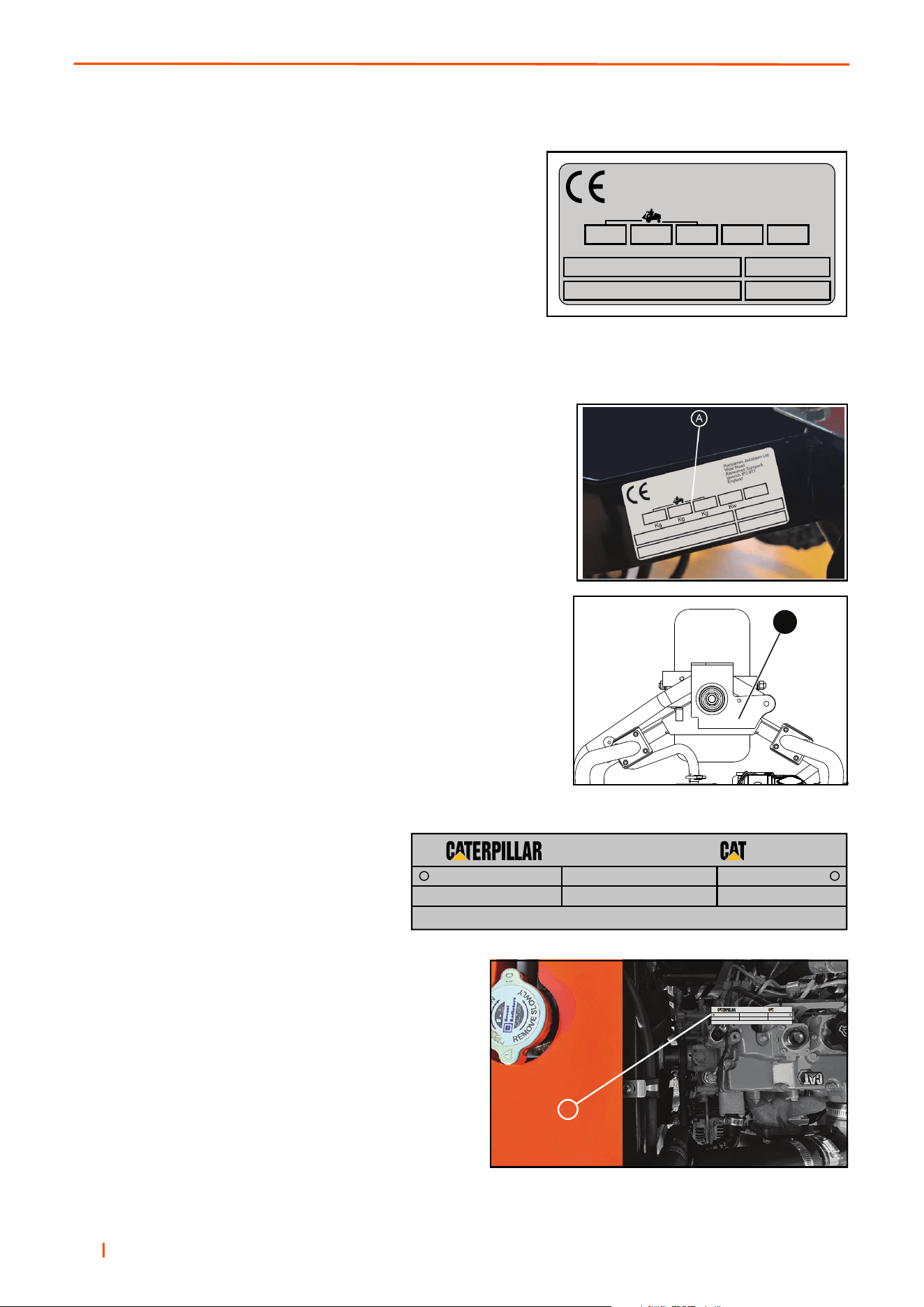
1.2 PRODUCTION IDENTIFICATION _________________________________________
A. Maximum front axle load in Kg (for machines being driven on
the highway)
B. Unladen weight, (No cutting implements or fuel (mass) in Kg
C. Maximum rear axle load in Kg (for machines being driven on
the highway)
D. Power in Kw
E. Date code
F. Machine type (Designation)
G. Product code
H. Product name
I. Serial number
Location of Serial Number Plate
The serial number plate (A) is found on the right hand of the
chassis towards the rear of the front right hand wheel.
Chassis Stamp
The Serial number and date code (B) are marked on the right hand of
the
chassis towards the rear of the front right hand wheel.
Engine Identification
Serial Plate
Location of Serial Number Plate
The engine serial number is found on the top of the valve
cover toward the front of the mower. The label shows the
engine group and serial number.
The engine serial number is also found on the engine block.
Kg
Kw
Kg
Kg
West Road
Ransomes Europark
Ipswich IP3 9TT
England
A
B
CD
E
F
G
H
J
GY000301
ABCD
A
ARRANGEMENT NUMBERSERIAL NUMBER
ASSEMBLED IN (ALWAYS GIVE ALL NUMBERS) 2468
MODEL
®
®
A
ARRANGEMENT NUMBER
SERIAL NUMBER
ASSEMBLED IN XXXXXXXXXXXXXXXXXXXXX 2468
MODEL
®
®

B
en 5
FOREWORD 1
ROPS Serial Plate
A. Weight of ROPS
B. Date Code
C. Standard Used
D. Part Number
E. Used on Product
F. Serial Number
ROPS Serial Plate Location
The ROPS serial plate (C) is located at the base of the front of the
ROPS main beam.
C
D
E
Kg
A
F
Ransomes Jacobsen Ltd
West Road
Ransomes Europark
Ipswich IP3 9TT
England
B
C
D
E
Kg
A
F
W
es
t Road
Ran
som
e
s
E
urop
ark
Ip
s
w
i
c
h
I
P
3
9TT
Eng
l
and
B
C
D
E
Kg
A
F
West Road
Ransomes Europark
Ipswich IP3 9TT
England
B

en 6
1 FOREWORD
1.3 GUIDELINES FOR THE DISPOSAL OF SCRAP PRODUCTS __________________
1.3.1 DURING SERVICE LIFE ______________________________________________
Used oil, oil filters and engine coolant are hazardous materials. Recommended procedures must be followed for
their safe removal.
If a fluid leaks, contain the spill to make sure that the leak does not flow into the ground or drainage system. Fol-
low the local laws to make sure that leaks are controlled safely.
The maintenance procedures in this manual make sure that the damage that the machine can cause in the local
environment is controlled safely.
When the machine completes its full service life, the following actions must be taken.
1.3.2 END OF SERVICE LIFE _______________________________________________
These guidelines must be used with applicable Health, Safety and Environmental laws. Always use the approved
local waste disposal and agencies for recycled materials.
• Park the machine in a location to use all of the necessary lifting equipment.
• Use correct tools and Personal Protective Equipment (PPE) and take instruction from the technical manuals
applicable to the machine.
• Remove and store correctly
• Batteries
• Fuel
• Engine coolant
• Oils
• Disassemble the structure of the machine and refer to the technical manuals where applicable. Give attention
to parts that have mechanical pressure or tension applied to the part in the machine,including springs.
• Items that continue to have a service life must be separated and returned to the local store.
• items that are worn must be separated into the material groups and removed according to the agencies for
recycled materials that are available. Common types are as follows:
• Steel
• Non ferrous metals
• Aluminium
• Brass
• Copper
• Plastic materials
• Identified
• Can be recycled
• Can not be recycled
• Not identified
• Rubber
• Electrical and Electronic Components
• If an item is not easily separated into different material groups, the material must be added to the “General
discarded materials” area.
• Do not burn discarded materials.
Change the machinery records to show that the machine is not in service and is discarded. Supply this serial
number to Ransomes Jacobsen Limited Warranty Department to close their records.

B
en 7
FOREWORD 1
1.4 PARTS MANUAL______________________________________________________
In compliance with the ISO14001 standard, Ransomes Jacobsen Limited does not send a paper parts manual
with every product.
To refer to a parts list for this mower you have two options:
1. Website – www.jacobsen.com and select the “FIND A MANUAL” tab at the top, search our catalogue of
current Jacobsen Turf Equipment for parts, and product information. Search by product name to access PDF
version of the parts manual.
Complete the form included in the technical manual pack supplied with the machine if you require a paper copy of
the parts manual.
1.5 KEY NUMBERS_______________________________________________________
Record the key numbers shown below:
Starter Switch:_ _ _ _ _ _ _ _ _ _ _ _ _ _ _ _ _ _ _ _ _ _ _ _ _ _ _ _ _ _ _ _ _ _ _ _ _ _ _ _
Diesel tank: _ _ _ _ _ _ _ _ _ _ _ _ _ _ _ _ _ _ _ _ _ _ _ _ _ _ _ _ _ _ _ _ _ _ _ _ _ _ _ _ _
Record the machine and engine numbers shown below:
The machine serial number is found on the registration plate and the engine serial number can be found on
the rocker cover.
Machine Number: _ _ _ _ _ _ _ _ _ _ _ _ _ _ _ _ _ _ _ _ _ _ _ _ _ _ _ _ _ _ _ _ _ _ _ _ _ _ _
Engine Number:_ _ _ _ _ _ _ _ _ _ _ _ _ _ _ _ _ _ _ _ _ _ _ _ _ _ _ _ _ _ _ _ _ _ _ _ _ _ _ _

en 8
1 FOREWORD
NOTES

en 9
SAFETY 2
2.1 HOW TO OPERATE SAFELY ____________________________________________
2.2 SAFE OPERATION ____________________________________________________
A. Read the Operator’s Manual and other training material. If the operator or technician can not read this manual,
the owner is responsible to describe this material to the operators and technicians. Manuals in additional lan-
guages may be available on the Jacobsen website.
B. Read all of the instructions for this mower carefully. Know the controls and the correct operation of the equip-
ment.
C. Children or persons who do not understand these instructions must not use the mower. The local regulations
can limit the age of the operator.
D. Never use a mower near persons, including children or animals.
— Parts could be ejected from the machine at high speed in certain circumstances. The hazard area, particu-
larly in front of and behind the machine, must be cleared of any persons, animals or objects before starting.
— Any use of the machine without verification of the hazard area can lead to serious or fatal accidents.
E. Any use of the machine without verification of the hazard area can lead to serious or fatal accidents.
F. Remember that the operator or owner is responsible for accidents or hazards that occur to other persons or
their property.
G. Never carry passengers.
H. Never allow persons to operate or service the mower or its attachments without correct instructions.
I. Do not operate equipment while tired, sick or whilst under the influence of alcohol or drugs.
2.3 PREPARATION _______________________________________________________
A. When you operate the mower, wear correct clothing, slip resistant work shoes or boots, work gloves, hard hat,
safety glasses and hearing protection. Long hair, loose clothing or jewelry can be caught in moving parts.
B. Do not operate the equipment with the Interlock System disconnected or the system does not operate cor-
rectly. Do not disconnect or prevent the operation of any switch.
C. Never operate equipment that is not in correct order or without decals, guards, shields, deflectors or other pro-
tective devices fastened. When you mow with a side discharge deck, DO NOT operate the cutting unit without
the discharge chute installed.
D. Inspect the mower before you operate the mower. Check the tyre pressure, engine oil level, the radiator cool-
ant level and the air cleaner indicator. Fuel is flammable. Use caution when you add the fuel to the mower.
E. Operate the mower in daylight or in good artificial light. Use caution when you operate the mower during bad
weather. Never operate the mower with lightning in the area.
F. Inspect the area to select the accessories and attachments that are needed to correctly and safely do the job.
Only use parts, accessories and attachments approved by Jacobsen.
G. Be careful of holes in the terrain and other hazards that are not visible.
H. Inspect the area where the equipment is operated. Remove all objects you can find before you operate. Be
careful of obstructions above the ground (low tree limbs, electrical wires) and also underground obstacles
(sprinklers, pipes, tree roots). Enter a new area carefully. Look for possible hazards.
WARNING
EQUIPMENT OPERATED INCORRECTLY OR WITHOUT TRAINING CAN BE DANGEROUS.
Know the location and correct operation of controls. Operators without experience must receive instruction
from another person that knows the correct operation of the equipment before you operate the mower.
Only use parts, accessories and attachments approved by Jacobsen.
!

en 10
2 SAFETY
I. Inspect the cutting system before you start the mower. Make sure the blades are free to rotate. When you
rotate one blade, other blades can rotate.
2.4 OPERATION _________________________________________________________
A.Never operate the engine without enough ventilation or in an enclosed area. The carbon monoxide in the
exhaust fumes can increase to dangerous levels.
B. Never carry passengers. Keep other persons or animals away from the mower.
C. Disengage all drives and engage the park brake before you start the engine. Only start the engine with the
operator in the seat. Never start the engine with persons near the mower.
D. Keep your legs, arms and body inside the operator compartment while the mower is in operation. Keep your
hands and feet away from the cutting units.
E. Do not use on the slopes greater than the safe slope limit for the equipment.
F. To guard against over turning or loss of control:
• Operate the mower up and down on the face of slopes (vertically), but not across the face (horizontally).
• Do not start or stop suddenly on slopes.
• Decrease the speed when you operate on slopes or when you must turn. Use caution when you change
direction. Turf condition can change the mower stability.
• Use caution when you operate the mower near drop-offs, ditches or embankments.
• Be careful of holes in the terrain and other hazards that are not visible.
G. When you drive in the reverse direction, look behind you and down to make sure the path is clear. Do not oper-
ate the cutting units when you drive in the reverse direction.
H. Use caution when you go near corners, trees or other objects that can prevent a clear view.
I. Equipment must meet the current regulations to be driven on the public roads.
J. Before you move across or operate on the paths or roads, turn off the PTO switch, lift the mowers and travel at
decreased speed. Look for traffic.
K. Stop the blades when the mower is on any surface that is not grass.
L. Do not release the cut grass in the direction of persons or allow persons near the mower while in operation.
M. Do not operate the mower with damaged guards or without safety devices in position.
N. Do not change the engine governor setting or over-speed the engine. Never change or tamper with adjusters
that are closed with a seal for the engine speed control.
O. Before you leave the operator compartment, for any reason:
• Disengage all the drives and lower attachments to the ground.
• Engage the park brake.
• Stop the engine and remove the key.
P. When you hit an object or mower starts to cause the vibration that is not normal, inspect the mower for damage
and make repairs.
Q. Decrease the throttle setting before you stop the engine.
R. Do not use this equipment for uses that the mower was not made for.
S. The machine and its cutting units are designed for use on maintained turf surfaces. Use of the machine with its
cutting units engaged on hard and rough surfaces could rapidly decrease design life of components and
potentially cause acute damage to the units making them unsafe for operation.
2.5 ROPS AND CABIN ____________________________________________________
A. The ROPS/Cabin is a safety device. Keep the ROPS in the vertical and locked position. Always use the seat
belt when you operate the mower. Make sure the seat belt can be released quickly in an emergency.

en 11
SAFETY 2
B. Only operate the mower with the ROPS in the folded position on flat and level surfaces when necessary. Do
not operate the mower with the ROPS in the folded position on slopes, near sharp edges or near water. On a
ROPS machine there is no roll over protection with the ROPS in the folded position.
C. Check for clearance before you drive below objects. Do not contact tree branches, electrical wires or other
objects with the ROPS/Cabin.
D. Do not use the seat belt with the ROPS in the folded position.
E. Inspect the ROPS/Cabin for damage. Keep hardware fastened.
F. Do not weld, drill, change or bend the structure. Replace a damaged ROPS/Cabin. Do not try to correct a dam-
aged ROPS/Cabin frame.
G. Do not remove the ROPS/Cabin from the mower other than for maintenance access. Ensure to refit
before use.
H. Ransomes Jacobsen must approve any changes to the ROPS/Cabins.
2.6 SAFE HANDLING OF FUELS____________________________________________
A. The fuel and the fuel vapors are flammable. Use caution when you add the fuel to the mower. The fuel vapors
can cause an explosion.
B. Never use the containers that are not approved to keep or transfer fuel.
C. Never keep the mower or fuel containers near an open flame or any device that can cause the ignition of fuel
or fuel vapors.
D. Never fill the fuel containers inside a vehicle or on a truck or trailer with a plastic liner. Always put the fuel con-
tainer on the ground away from your vehicle before you fill the container.
E. Refuel the mower before you start the engine. When the engine is in operation or while the engine is hot, never
remove the fuel cap or add fuel to the mower.
F. Refuel outdoors only and do not smoke when you add fuel. Extinguish all types of ignition.
G. The fuel nozzle must touch the rim of the fuel tank when you add fuel to the mower. Do not use a device to lock
the fuel nozzle in the open position.
H. Do not over fill the fuel tank. Leave at least 1 inch (25 mm) below the filler neck.
I. Always tighten the fuel tank cap and container cap after you add fuel.
J. If the fuel spills on your clothing, change your clothing immediately.
2.7 MAINTENANCE AND STORAGE _________________________________________
A. Before you clean, adjust or repair this equipment, push PTO switch to the OFF position, lower the cutting unit
to the ground, engage the park brake, stop the engine and remove the key.
B. Make sure the mower is parked on a solid and level surface.
C. Never work on a mower that is lifted only by a Jack. Always use Axle stands.
D. Never allow persons to service the mower or its attachments without correct instructions.
E. When the mower is parked, put into storage or left without an operator, lower the cutting device unless a posi-
tive mechanical lock is used.
- Do not keep fuel near flames or drain the fuel inside a building.
F. Disconnect the battery before you service the mower. Always disconnect the negative battery cable before the
positive battery cable. Always connect the positive battery cable before the negative battery cable.
G. Charge the battery in an area with good airflow. The battery can release hydrogen gas that is explosive. To
prevent an explosion, keep any device that can cause sparks or flames away from the battery.
H. Disconnect the battery charger from the power supply before you connect or disconnect the battery charger to
the battery. Wear protective clothing and use insulated tools when you service the battery.
I. Be careful and wear gloves when you check or service the cutting unit blades. Replace any damaged blades,
do not try to correct a damaged blade.

en 12
2 SAFETY
J. Keep your hands and feet away from parts that move. Do not adjust the mower with the engine in operation,
unless the adjustment needs the engine in operation.
K. Take care working on cutting units and moving parts with stored energy.
L. To prevent injury from the hot, high pressure oil, never use your hands to check for oil leaks. Use paper or
cardboard to find leaks.
M. The hydraulic fluid pressure can have enough force to enter your skin. If hydraulic fluid has entered your skin,
seek medical attention immediately.
N. When you service the hydraulic system, make sure the hydraulic fittings, tubes and hoses are tightened to the
correct torque (where applicable). Make sure the hydraulic system is in good condition before you start the
engine.
O. Keep the mower and the engine clean.
P. Allow the engine to become cool before storage and always remove the ignition key.
Q. Keep all nuts, bolts and screws tight to make sure the equipment is in safe condition.
R. DO NOT operate the machine if you have worn or damaged parts for safety. Replace damaged or worn decals.
Only use parts, accessories and attachments approved by Ransomes Jacobsen.
S. To decrease the fire hazard, remove materials that burn from the engine, muffler, battery tray and fuel
tank area.
T. Disconnect the battery and controller connectors before you weld on this mower.
2.8 WHEN YOU PUT THE MOWER ON TO TRAILER____________________________
A. Be careful when you load or unload the mower on a trailer. The trailer must be wider than the mower and can
carry the weight of the mower.
B. Use a full-width ramp to load or unload the mower on a trailer.
C. Use appropriate securing methods to fasten the mower to the trailer. Both front and rear straps must be sent
down and towards the sides of trailer.
D. Make sure that all latches are correctly fastened.

en 13
SAFETY 2
2.9 IMPORTANT SAFETY NOTES ___________________________________________
DANGER:
Indicates a dangerous condition that WILL cause death or injury unless it is prevented.
WARNING:
Indicates a dangerous condition that CAN cause death or injury unless it is prevented.
CAUTION:
Indicates a dangerous condition that can cause injury and property damage unless it is prevented. Also, the label
can indicate work procedures that are not safe.
IMPORTANT:
Some illustrations in this manual can show shields, guards or plates removed for clarity. This equipment must not
be operated without these devices correctly fastened and in position.
By following all instructions in this manual, you increase the life of your machine and keep its maximum perfor-
mance. Adjustments and maintenance must always be done by an approved technician.
If a service is needed contact your authorized Jacobsen Dealer or after sales for additional information or help.
WARNING
The Interlock System on this mower prevents the starting of the mower unless a.) The Park Brake is Engaged.
b.) The mow switch is in the OFF position, c.) The traction pedal is in the Neutral position. d) The operator is in
the seat. The system stops the engine when the operator leaves the seat a.) without the Park Brake engaged
and b.) the mow switch is not in the OFF position. NEVER operate the mower unless the Interlock System
is working.
WARNING
1. Before leaving the operator’s position for any reason:
a. Return traction pedal to the Neutral position.
b. Disengage all drives.
c. Lower all cutting units to the ground.
d. Engage Park Brake.
e. Stop the engine and remove the ignition key.
2. Keep your hands, feet, and clothing away from moving parts. Wait for all movement to stop before you
clean, adjust, or service the machine.
3. Keep the area of operation clear of all persons and animals.
4. Never carry any passengers.
Never operate the equipment without guards and deflectors in position.
This safety alert symbol is used to alert you to possible hazards.
!
!

en 14
2 SAFETY
WARNING
California Proposition 65
Engine exhaust, some of its constituents, and some vehicle components contain or release chemicals known to
the state of California to cause cancer and birth defects or other reproductive harm.
WARNING
To prevent injury from the hot oil at high pressure, DO NOT use your hands to check for oil leaks.
Make sure that you use paper or cardboard.
Release of hydraulic fluid at high pressure has enough force to enter through the skin. If the fluid enters
through the skin, you must seek medical attention immediately.
WARNING
When the machine is driven off-road, a seat belt must be worn only when a ROPS frame is in position.
This warning is because a seat belt must be worn with a ROPS to follow the Machinery Directive,
2006/42/EC Sections 3.2.2, Seating & 3.4.3, Rollover. (ANSI B71.4-2012 section 20.7)
Ransomes Jacobsen Limited recommends that the owner/user of the machine completes a site specific risk
assessment of the machine to find any conditions that do not follow this rule.
e.g. when you drive the machine next to water.
WARNING
Explosive gases are released by batteries. The battery contains corrosive acid and supplies an electrical
current that is high enough to cause injuries to the body.
WARNING
You must not use this machine to tow other vehicles.
WARNING
Ear protection must be worn when you operate machines with
an operator ear noise level of more than 85dB(A) Leq
!
!
!
!
!
!

en 15
SAFETY 2
WARNING
Vibration Exposure Limits
Exposure limits are calculated as a combination of the vibration level (magnitude) of the tool and the Daily
Exposure Time (Trigger Time). e.g. A product with 5m/s² vibration can be used up to 2 hours/day
to reach the EAV and up to 8 hours/day to reach the ELV.
Exposure Action Value (EAV) - Daily vibration exposure A(8) = 2.5m/s²
Where daily vibration exposure A(8) is below 2.5m/s² the risk is relatively low and no
action need be taken.
Exposure Limit Value (ELV) - Daily Vibration Exposure A(8) = 5.0m/s²
If several tools are use the exposure values must be combined:
Total exposure is then the combined value of the activities.
WARNING
Never mow if there is a risk of lightning or you hear thunder. If you are in the middle of mowing, stop in a safe
place, turn off the engine and go inside a building.
CAUTION
When you do any welding on the machine, the battery, controller and display must be disconnected before
you start. You must not open the controller. If the controller is opened, this can void all of the warranties and
can cause the failure of the machine
CAUTION
Personal Protective Equipment (PPE), for example safety glasses, safety footwear, work gloves
and ear protection must be used after the owner/user completes a site specific risk assessment of the
mower to prevent injury.
!
!
!
!

en 16
3 SPECIFICATIONS
3.1 ENGINE SPECIFICATION_______________________________________________
CAT® - C0.7
Cycle 4 stroke
Number of Cylinders 3
Bore & Stroke 67mm x 68mm (2.64 in) - 72mm (2.83 in)
Displacement 0.762 Litres (46.5 in³)
Compression ratio 22.1:1
Gross Intermittent Power 13.3kW (17.8hp) @ 3600rpm
Maximum Speed: 3400 ± 50 RPM (No load) 3500 ± 50 RPM (No load)
Idle Speed: 1700 ± 100 RPM 1800 ± 50 RPM
Order of Firing 1-2-3
Direction of Rotation Counter-clockwise (viewed from flywheel side)
Injection Pump Bosch MD type mini pump
Injection Pressure 13.73 MPa (140kgf/cm²)
Injection Timing (Before T.D.C.) 21° 20°
Compression Ratio 23.5:1
Fuel: No. 2-D Diesel fuel (ASTM D975)
Lubrication (API Classification) Above CF grade
Oil Sump Capacity: Maximum: 3.05 Litres / 5.36 pints - Minimum: 2.35 Litres / 4.13 pints
Dimensions (length x width x height) 480mm (18.9 in) x 371mm (14.6 in) x 528mm (20.8 in)
Dry Weight 71kg
Starting System Cell starter (with glow plug)
Standard Starting Motor cold start limit -20°C - (-4°F)
en 17
SPECIFICATIONS 3
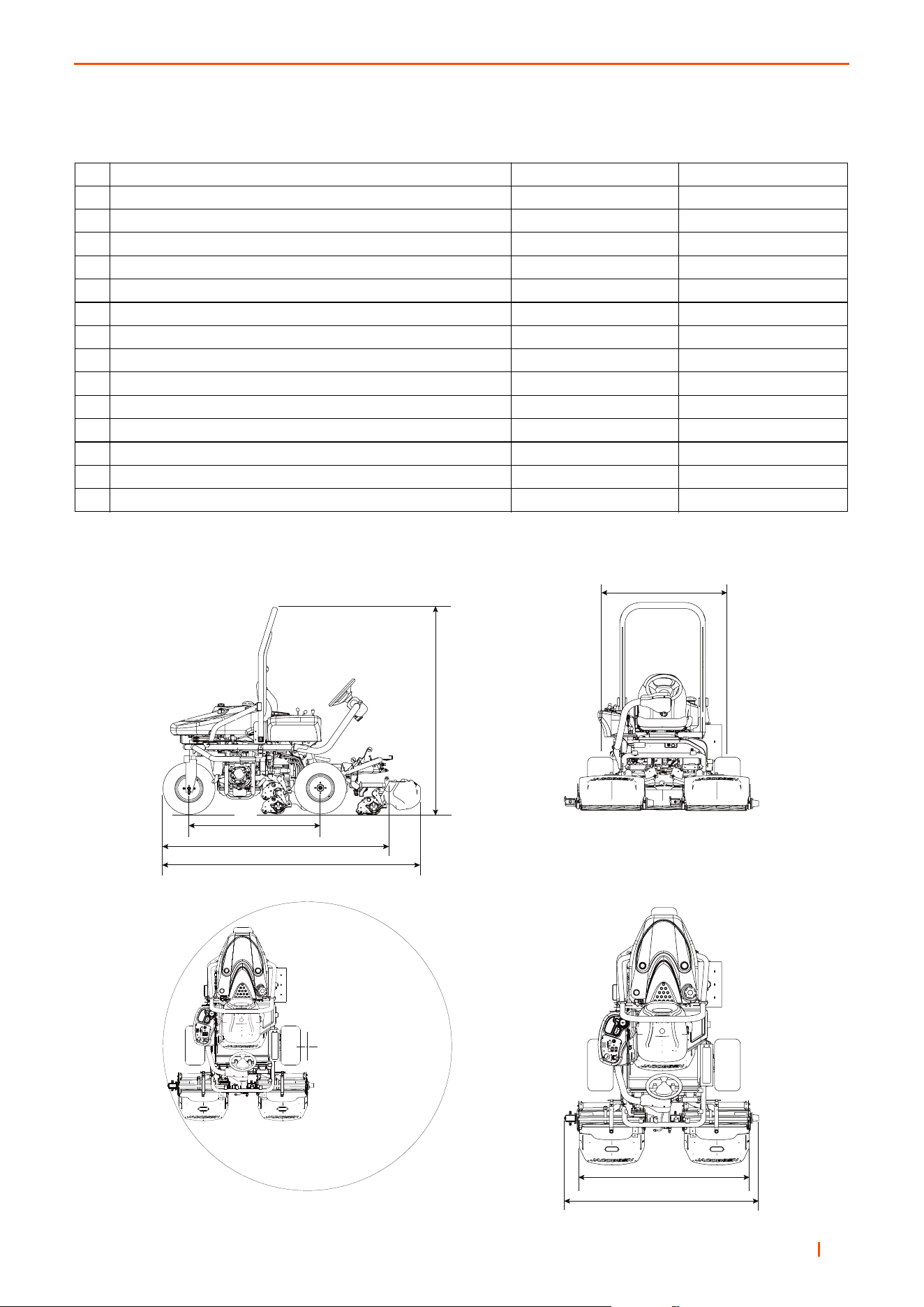
3.2 DIMENSIONS & WEIGHTS______________________________________________
A Width of Cut: 160 cm 63 inches
B Overall Width Cutting: 188 cm 74 inches
Overall Width Transport (minimum): 186 cm 73.25 inches
C Overall Height with ROPS Frame: 196.5 cm 77.38 inches
D Overall Length Without Grass Boxes: 219 cm 86.2 inches
E Overall Length With Grass Boxes: 250 cm 98.4 inches
F Wheel Track: 121.7 cm 48 inches
G Wheel Base 2 Wheel Drive: 133.2 cm 52.44 inches
G Wheel Base 3 Wheel Drive: 125.5 cm 49.5 inches
H Turning Circle 2 Wheel Drive: 368 cm 144.88 inches
H Turning Circle 3 Wheel Drive: 393.8 cm 155 inches
Weight of Diesel Machine, No Fuel, Plus ROPS: 590kg 1390 lbs
Weight of one Cutting Unit 11 Knife 31.6 kg 69.6 lbs
Weight of one Brush & Groomer Kit: 7 kg 15.4 lbs
Weight Diesel Fuel 54l (14.25 US Gallons) 46 kg 101 lb
A
B
F
G
D
E
C
H

en 18
3 SPECIFICATIONS
3.3 MACHINE SPECIFICATION _____________________________________________
Frame construction: Welded tubular steel chassis.
Cutting unit drive: Direct Drive hydrostatic reel drive pump, bi-directional hydraulic gear motor with reel control
and Backlap valves.
Transmission:Variable displacement hydrostatic pump with low speed high torque wheel motors
Speeds:
Cutting: 0 - 6 km/h (0 - 3.7 mph) Forward
0 - 3 km/h (0 - 1.9 mph) Reverse
Transport: 0 - 12 km/h (0 - 7.5 mph) Forward
0 - 3 km/h (0 - 1.9 mph) Reverse
Steering:Hydrostatic power steering 2.5 turns lock to lock, with 330mm (13 inches) dia steering wheel.
Ground pressure: 1 kg/cm² (14 psi) (Dependent on tyre pressures and accessories fitted)
Brakes: Hydrostatic braking with 152mm (6 inches) Caliper disc parking brakes on front wheels.
Battery:
Yuasa YBX3063 12 Volt 440A 45Ah
TYRE PRESSURE
Product
Front Wheel Rear Wheel
Tyre Size Tyre Type Tyre Pressure Tyre Size Tyre Type Tyre Pressure
GP400 20 x 10.00 - 10 OTR Smooth
0.7 bar
(10 psi)
20 x 10.00 - 10 OTR Smooth
0.7 bar
(10 psi)

en 19
SPECIFICATIONS 3
3.4 VIBRATION LEVEL ____________________________________________________
The machine was tested for hand/arm vibration levels. The operator was in the normal position to drive the
vehicle, with two hands on the steering mechanism. The engine was in operation and the cutting device was in
rotation, while the machine was not moving.
The Machinery Safety Directive 2006/42/EC
By compliance to:
The Lawnmower Standard BS EN ISO 5395
Referenced to Hand/Arm: BS EN ISO20643:2008
Information Supplied for Physical Agents Directive 2002/44/EC
By reference to:
Hand/Arm Standards: BS EN ISO 5349-1 (2001)
BS EN ISO 5349-2 (2002)
The machine was tested for Whole Body vibration levels. The operator was in the normal position to drive the
vehicle, with two hands on the steering mechanism. The cutting device was in rotation with the machine driven in
a straight line at 6 Km/hr on a level and cut lawn.
The Machinery Safety Directive 2006/42/EC
By compliance to:
Whole Body EN1032:2003
Information Supplied for Physical Agents Directive 2002/44/EC
By reference to:
Whole Body Standards BS EN ISO 2631-1 (1997)
measurements according to the requirements of BS EN ISO 5395
GP400 Diesel
Hand / Arm
Acceleration
Level
Series DDE with ROPS
Max. LH or RH Accelerations m/s²
Mean Value of X, Y, Z Aeq
1.68 ± 0.40
GP400 Diesel
Whole Body
Acceleration
Level
Series DDE with ROPS
Max. Seat Accelerations m/s²
Mean Value of X, Y, Z Aeq
0.36 ± 1.57

en 20
3 SPECIFICATIONS
3.5 NOISE LEVEL ________________________________________________________
The Machinery Safety Directive 2006/42/EC
And
Exposure Of Workers To The Risks Arising From Physical Agents (Noise) Directive 2003/10/EC
By compliance to:
The Lawnmower Standard BS EN ISO 5395:2013
And
Sound Pressure Standard EN ISO 3746: 2010
GP400 Diesel Measured Sound Pressure 88.8 dB(A) ± 1.24 LWA
When the machine was tested for sound power (Noise in the Environment).
The Machinery Safety Directive 2006/42/EC
And
Noise Emission In The Environment By Equipment For Use Outdoors
Directive 2000/14/EC
By compliance to:
Sound Power Standard EN ISO 3744:1995
GP400 Diesel Measured Sound Power 103.7 dB(A) ± 1.24 LWA
3.6 SLOPES ____________________________________________________________
DO NOT USE ON SLOPES GREATER THAN 16°. The 16° slope was calculated using static stability
measurements according to the requirements of BS EN ISO 5395-2013

en 21
SPECIFICATIONS 3
3.7 CUTTING UNIT SPECIFICATION _________________________________________
NOTE: These cutting units are designed to cut grass of maximum height 12mm (15/32 in) down to the available
height of cut range, removing no more than 1mm (3/64 in) to 2mm (5/64 in) with each pass.
7 Blade 9 Blade 11 Blade 15 Blade Verticut
Construction Fabricated steel construction
Reel Length 559mm (22 in) 559mm (22 in) 559mm (22 in) 559mm (22 in) 559mm (22 in)
Number of Knives 7 9 11 15 N/A
Number of Blades N/A N/A N/A N/A 26
Reel Diameter (New) 127mm (5 in) 127mm (5 in) 127mm (5 in) 127mm (5 in) N/A
Minimum Reel Diameter
(Before Replacement)
117.5mm
(4.6 in)
117.5mm
(4.6 in)
117.5mm
(4.6 in)
117.5mm
(4.6 in)
N/A
Height of Cut True-
Set™ Reel (Standard
Blade)
1.6mm - 11.1mm (1/16 in - 7/16 in)
Height of Cut Classic
XP™ Reel (Standard
Blade)
2.5mm - 16mm (0.1 in - 0.63 in)
Height of Cut Classic
XP™ Reel (Tourna-
ment Blade)
2mm - 16mm (0.78 in - 0.63 in)
Bedknife to Reel adjust-
ment TrueSet™ Reel
Micro-adjusters
Bedknife to Reel adjust-
ment Classic XP™ Reel
Opposed Set Screw
Rolls (Smooth &
Grooved)
50 mm (2 in) Diameter
Height of Cut Adjust-
ment TrueSet™ Reel &
Classic XP™ Reel
Screw adjusters on front roll
Transmission By hydraulic motor direct to reel.
Maximum Reel Speed
at Maximum PTO
Speed
2200rpm

en 22
3 SPECIFICATIONS
3.8 CUTTING PERFORMANCE _____________________________________________
3.9 RECOMMENDED LUBRICANTS_________________________________________
Engine oil:
Diesel:Should be to A.P.I. CK-4 or CAT
® ECF-3 Classification CD grades. [10W-30]
Grease: For rear axle: K NATE (RJL No. 4213860), or equivalent to MIL-G-23549C, MIL-G-2345C,
DIN 51 825, DIN 51 818.
General: Lithium based general purpose grease.
3.10 ACCESSORIES ______________________________________________________
Orange Touch-up Paint (12 oz. spray) ..................554598
Rear Roller Cleaner ................................................62820
Turf Groomer 1/4” Spacing......................................67912
Turf Groomer 1/2” Spacing......................................67914
High Cut Roller Kit...................................................68634
Motor Adapter Kit ..................................................894991
Magknife Kit
22 in. Medium Section Magknife Kit....................4266571
22 in. Tournament Magknife Kit...........................4266551
22 in. Super Tournament Magknife Kit ................4266570
Solid Rollers
22 in. with Scraper (Light) .......................................68530
22 in. with Scraper ..................................................68641
22 in. Solid Tube Rear Roller ..............................1004990
Grooved Rollers
22 in. Assembled Disc.............................................68527
22 in. Machined Aluminum ......................................68614
22 in. Machined Steel............................................. 68613
22 in. Segmented Roller 68673
Frequency of Cut
@ 2200rpm reel speed
Clip rate
@ 2200rpm reel speed
Blades mm/kph inches/mph
Cuts/metre
@ 6.04 kph
Cuts/yard
@ 3.74mph
7 1.247 0.079 41 37
8 0.963 0.061 52 48
11 0.789 0.050 64 59
15 0.584 0.037 87 80
TEMPERATURE VISCOSITY
Above 4°C (39°F) SAE30
Below 4°C (39°F) SAE5W-30 or SAE10W-30

en 23
SPECIFICATIONS 3
NOTES
en 24
4 DECALS
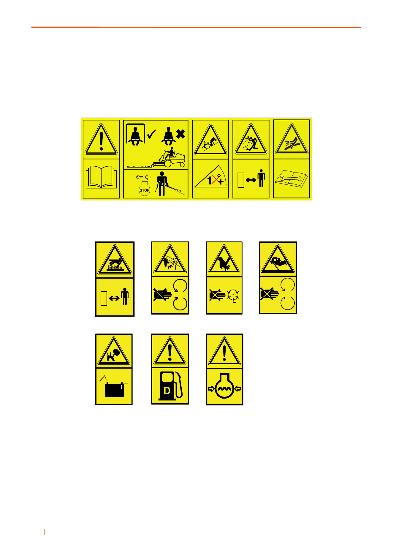
4.1 DECALS ____________________________________________________________
F G H K
L M N
6
A B
D
E C J

B
en 25
DECALS 4
A. Read Operator's Manual.
B. Keep a Safe Distance from the Machine.
C. Maximum permissible working slope. (See Accessories section for correct limit with various accessories).
D. Seat Belt Must be Worn When ROPS is Deployed. Do Not Wear Seat Belt When ROPS is Lowered.
Read Operators Manual.
E. Caution, Stop Engine & Remove the Starter Key Before Pressure Washing
F. Stay Clear of Hot Surfaces.
G. Do Not Open or Remove Safety Shields While the Engine is Running.
H. Caution Rotating Blades.
J. Avoid Fluid Escaping Under Pressure. Read Operators Manual for Service Procedures.
K. Do Not Remove Safety Shields While Engine is Running.
L. Danger of Explosion if the Battery Terminals are Short Circuited.
M. Caution Diesel Fuel
N. Caution Engine Coolant Under Pressure

en 26
4 DECALS
4.2 INSTRUCTION DECALS________________________________________________
1 Speed Control (Foot Pedal)
2 Engine Speed Control.
3 Parking Brake ‘P’.
4 Maximum Sound Power Level.
5 Jacking Point
6 Centre Unit raise / Lower Speed Adjustment
7 Use Low Or Ultra-low Sulphur Fuel
1
2
3
4
5
6
USE LOW OR
ULTRA-LOW
SULPHUR
FUEL ONLY
7

B
en 27
DECALS 4
NOTES
en 28
5 CONTROLS
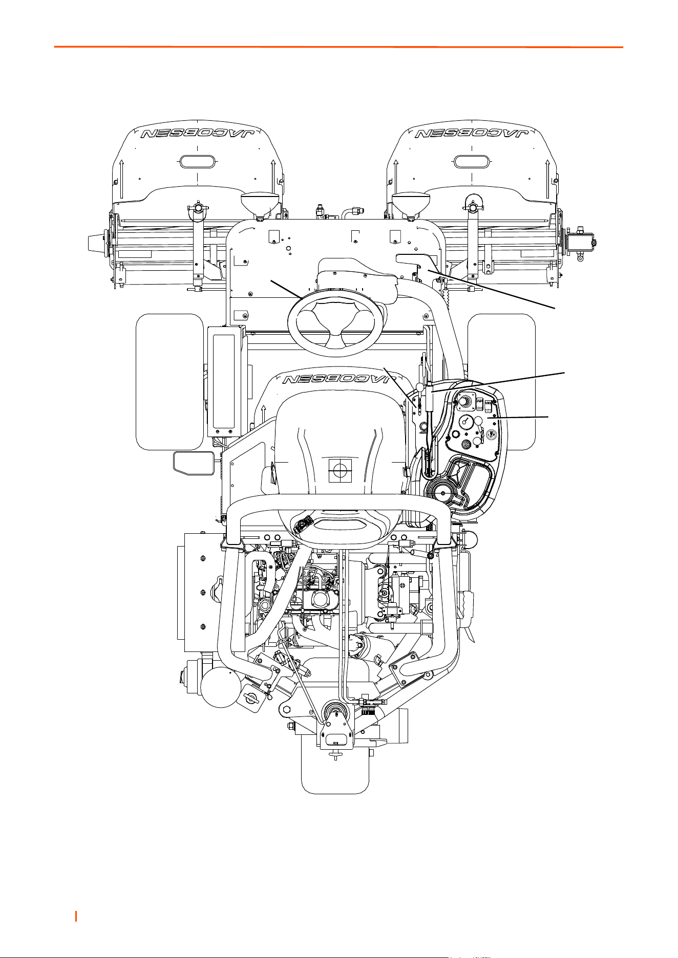
5.1 OPERATOR WORKSTATION ____________________________________________
5.2
5.2
5.3
5.5
5.4

B
en 29
CONTROLS 5
5.2 INSTRUMENT PANEL__________________________________________________
A: Starter Key Switch.
B: Throttle Control Lever.
C: Cutting Unit Switch (PTO).
D. Joystick.
E: Working Lights.
F. Engine Coolant Temperature.
G: Hour Meter.
H: Blocked Hydraulic Filter Warning Light.
J. Ignition Warning Light.
L. Mow / Transport Lever.
M Power Outlet.
N. Engine Oil Pressure.
P. Horn.
DIESEL
1234
12V
10A
B
M
QUARTZ
HOURS
CURTIS
1
10
D
C
E
F
P
A
J
L
N
G
H
en 30
5 CONTROLS
5.2.A STARTER KEY SWITCH _____________________________________________
The key switch has three positions:
OFF - prevents all electrical functions from operating. Switch must be in the OFF position to remove the key.
ON - Illuminates the red indicator lamp. This position is also for normal operation.
START - Activates the glow plugs & automatically cranks the engine after the glow plugs have pre-heated.
Release the key after engine starts (the switch automatically returns to ON).
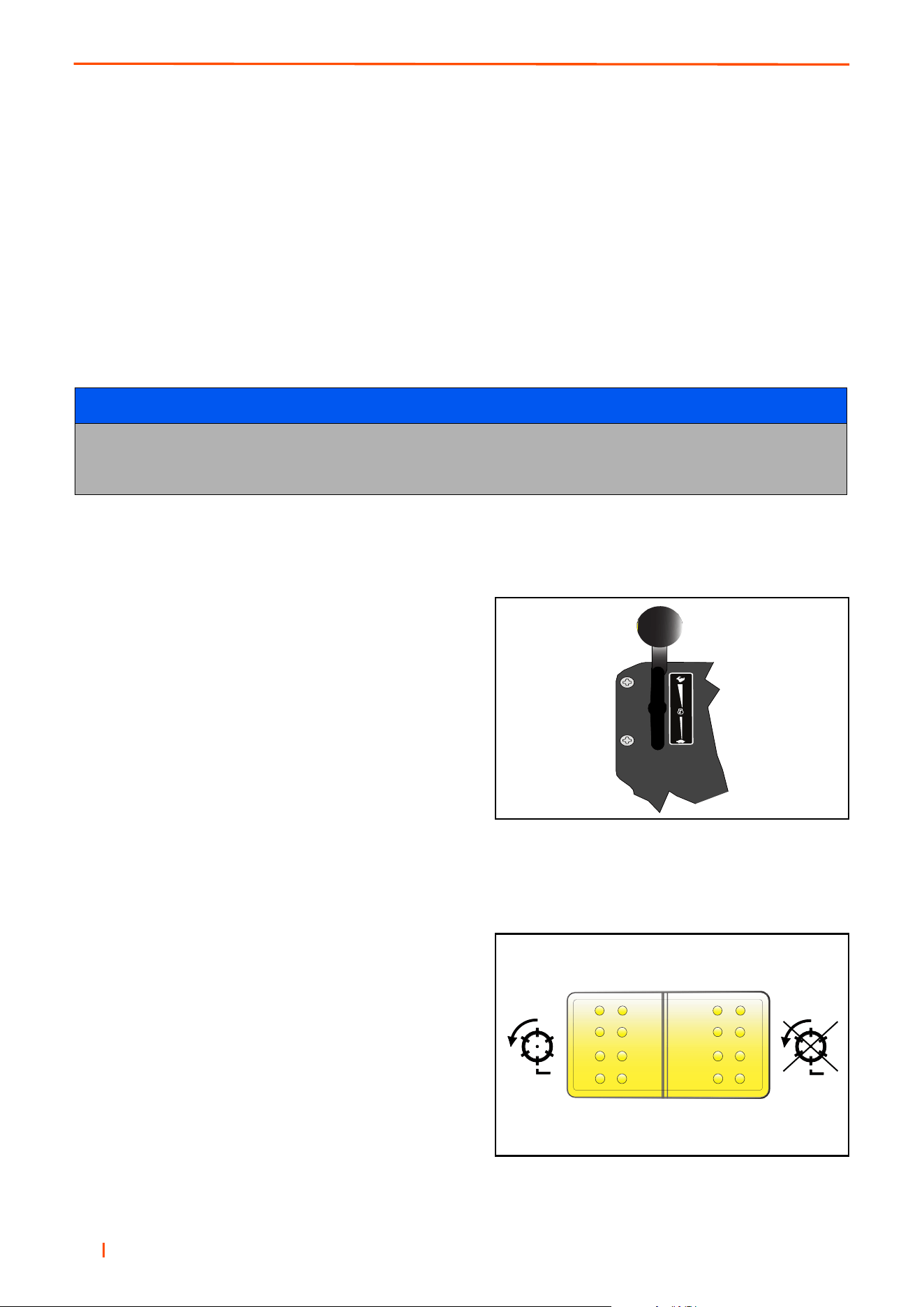
5.2.B THROTTLE CONTROL LEVER_________________________________________
The lever should be moved towards the front of the machine
to increase the engine speed and towards the rear of the
machine to decrease the engine speed.
NOTE: Engine should be used at full speed
5.2.C CUTTING UNIT SWITCH (PTO) ________________________________________
Colour Yellow.
To commence cutting ensure mow / transport lever is in
mow position and the units have been lowered.
Push bottom of the rocker switch and move joystick towards
the lower position.
To stop cutting unit rotation push top of rocker switch.
Cutting units stop rotating automatically when raised or the
operator leaves the seat.
NOTICE
If the engine fails to start, or if it “dies” for any reason, the ignition switch must be returned to the “off” position
before restarting is attempted. This feature prevents damage to the starter and flywheel teeth that can occur if
the starter is engaged while the engine is running. Wait 30 seconds before restarting engine.

B
en 31
CONTROLS 5
5.2.D JOYSTICK ________________________________________________________
The Mow/ Lift Joystick lowers and raises the cutting heads.
To Lower the Heads:
Move the joystick forwards (A) to lower the cutting heads. If
reel enable switch is on, reel rotation starts when the heads
are lowered.
To Raise the Heads:
Move the joystick backwards (B) to raise the cutting heads.
Reel rotation stops when the heads are raised.
5.2.E WORKING LIGHTS __________________________________________________
Colour Black.
The Working light Switch turns the two working lamps on
and off.
5.2.F ENGINE COOLANT TEMPERATURE ____________________________________
Gauge indicates engine coolant temperature.
5.2.G HOUR METER ______________________________________________________
Records the number of hours the engine has run. Use the
hour meter to manage a good scheduled maintenance
program (refer to the Maintenance Guide 7.2).
QUARTZ
HOURS
CURTIS
1
10
B
A

en 32
5 CONTROLS
5.2.H BLOCKED HYDRAULIC FILTER WARNING LIGHT ________________________
Monitors Hydraulic filter condition. Coloured yellow,
Illuminates prior to filter bypass valve operating, when
illuminated filter requires changing. Under cold start
conditions the LED may illuminate for 15 - 20 minutes until
the hydraulic oil reaches normal operating temperature.
This is normal, only if the LED remains illuminated after this
period should the element be changed.
5.2.I MULTIFUNCTION WARNING LIGHT
5.2.J MULTIFUNCTION WARNING LIGHT_____________________________________
When the ignition key is in the ON position, the red LED is
on continuously. When any of the safety interlocks are not
in their neutral position, the red LED flashes the applicable
code.
One flash every two seconds - Seat switch is not activated.
Two flashes every two seconds - Parking brake is not
applied.
Three flashes every two seconds - Reel drive engaged.
If the red LED continues to flash, the engine will not start.
The red LED flashes to indicate the operation of the glow
plugs on diesel engines only and the engine starts.
The red LED stays illuminated for two to three seconds, then goes out. If the engine is over temperature (Diesel
Only), the red LED flashes and the buzzer sounds twice every four seconds.
5.2.K OIL PRESSURE WARNING LIGHT______________________________________
Colour red
a. On when the engine oil pressure is too low for operation.

B
en 33
CONTROLS 5
5.2.L MOW / TRANSPORT LEVER __________________________________________
This lever limits the maximum traction speed for cutting and
allows engagement of reels.
5.2.M POWER OUTLET ___________________________________________________
Provides a 12 volt 10 amp power supply for accessories.
5.2.N HORN BUTTON _____________________________________________________
Situated on rear of the control panel. Press to sound
warning.
12V
10A
en 34
5 CONTROLS
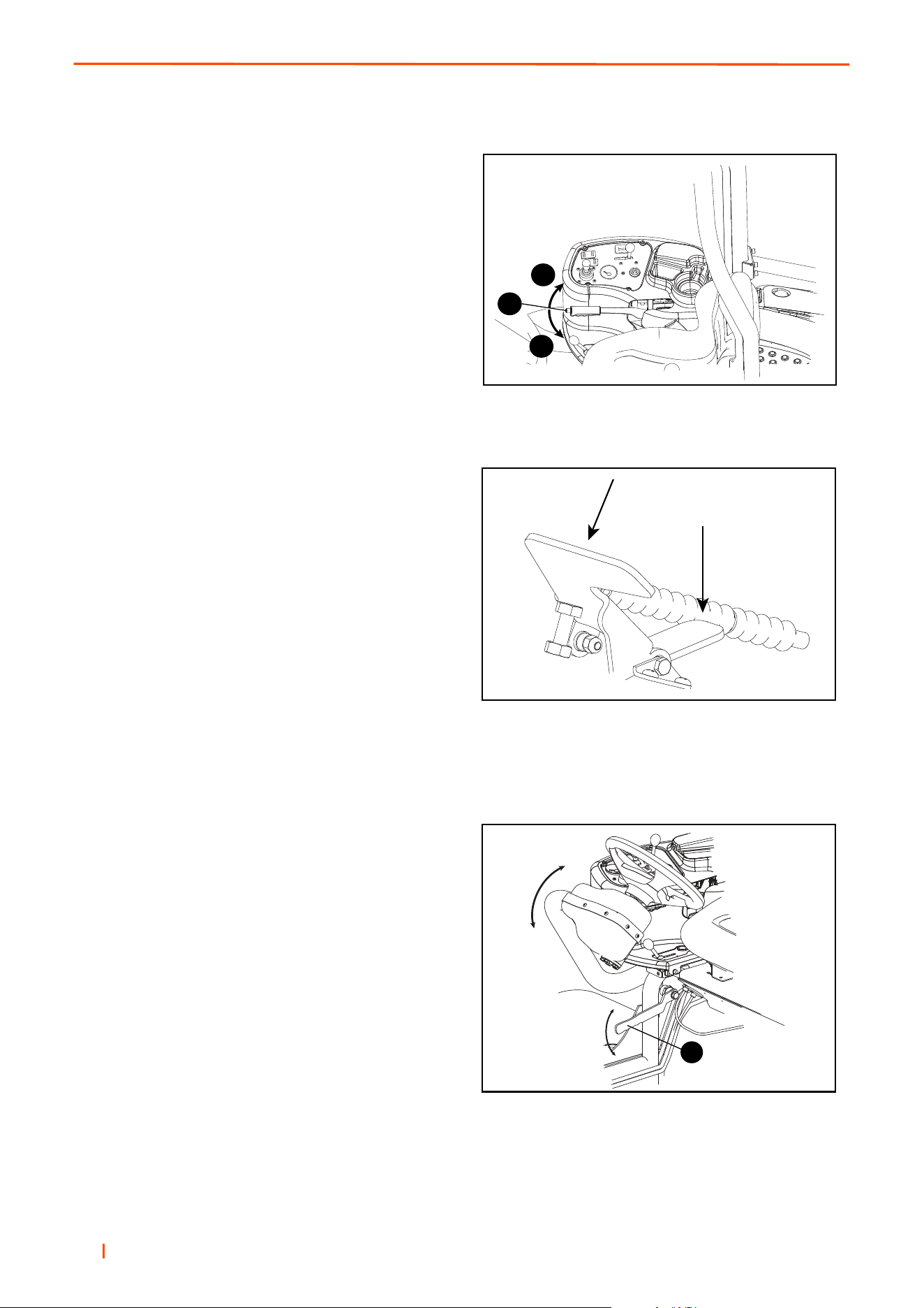
5.3 PARKING BRAKE _____________________________________________________
The Parking Brake can be engaged by depressing button
A and pulling the lever upwards to position B.
To release the parking brake depress button A and lower
lever to position C.
5.4 TRACTION PEDAL ____________________________________________________
The Direction/Speed Pedal controls speed and direction.
Depress front of pedal (A) to go forward, depress back of
pedal (B) to go backward. Increased movement of the
pedal will increase speed. To slow and stop the machine,
ease the pedal back to the neutral position. Proper braking
is provided by hydrostatic pressure.
NOTE
To reduce fatigue during normal forward operation, the
operator’s heel should rest on the floorboard next to the
pedal (not on the lower part of the pedal).
5.5 STEERING WHEEL____________________________________________________
The steering wheel is fitted to an adjustable arm to adjust
its height. Loosen the Locking Lever (A) to allow the steer-
ing wheel and control arm to be adjusted up or down.
Tighten the locking lever when steering wheel is at the
desired position.
A
B
C
A
B
A
B
en 35
CONTROLS 5
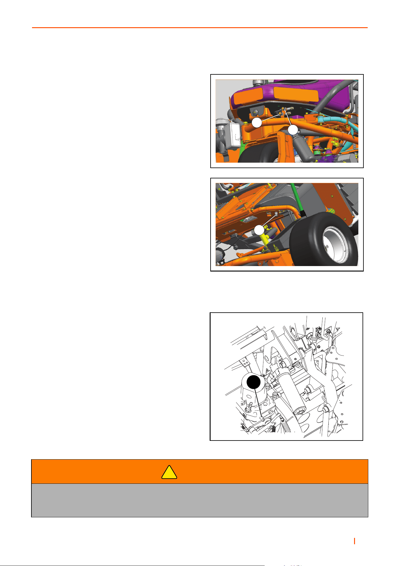
5.6 LIFT & LOWER RATE & SYNCHRONISATION CONTROL_____________________
The drop rate of the cutting units can be adjusted using
these controls.
Valves ‘A’ & ‘B’ are used to control the rate of lift and lower
for the centre cutting unit.
Valve ‘C’ is used to control the lift and lower rate for the
front cutting units.
Refer to section 6.7 for more detailed instructions on
setting and adjusting the soft drop.
5.7 FREE WHEEL ________________________________________________________
1. To push the machine, disengage the parking brake
2. Turn screw (A) located on the underside of the
transmission pump 180º counterclockwise. Set the
steering wheel so that the rear wheel is pointing
straight ahead.
3. After pushing the machine, return the screw (A) on
the pump to its operating position.
WARNING
The Free Wheel Facility Is For Recovery Purposes Only.
DO NOT tow the machine for more than a few metres, or allow the machine to free wheel
down slopes, even when unloading down ramps.
!
B
A
C
A

en 36
6 OPERATION
6.1 DAILY INSPECTION _____________________________________________________
1. Perform a visual inspection of the entire machine, look for signs of wear, loose hardware and missing or
damaged components. Check for fuel and oil leaks to ensure connections are tight and hoses and tubes are
in good condition.
2. Check the fuel supply, radiator coolant level, crankcase oil level, hydraulic oil level and the air cleaner is
clean. All fluids must be at the full mark with the engine cold.
3. Make sure all cutting implements are adjusted to the same height of cut.
4. Check all tyres for proper inflation. (Section 3.2).
Once checks 1-4 are complete, start machine and test the operator presence control. (Section 6.2).
6.2 OPERATOR PRESENCE AND SAFETY INTERLOCK SYSTEM___________________
1. The operator presence & safety interlock system prevents the engine from starting unless the operator is
seated, Park Brake is on, the Cutter Engage (PTO) switch is off, and the Traction Pedal is in the neutral
position. The system stops the engine after 3 seconds if the operator leaves the seat and the Park Brake is
off. If the operator leaves the seat with the Cutter Engage (PTO) switch on and the Park Brake on only the
cutters will stop.
2. Perform each of the following tests to ensure the operator presence & safety interlock system is functioning
properly. Stop the test and have the system inspected and repaired if any of the tests fail as listed below:
• The engine does not start in test 1;
• The engine does start during tests 2 or 3.
• The engine stops during test 4.
3. Refer to the chart below for each test and follow the check () marks across the chart. Shut engine off
between each test.
Test 1: Represents normal starting procedure. The operator is seated, parking brake is on, the operators
feet are off the pedals and the mower engagement device is off. The engine should start.
Test 2: The engine must not start if the mower engage device is on.
Test 3: The engine must not start if the parking brake is not applied.
Test 4: Start the engine in the normal manner, then turn mower engage device on and lift your weight
off the seat.
CAUTION
The daily inspection should be performed only when the engine is off and all fluids are cold. Lower
implements to the ground, engage Park Brake, stop engine and remove Ignition Key.
WARNING
Never operate the equipment with the operator presence & safety interlock system disengaged
or malfunctioning. Do not disconnect or bypass any switch.
!
!

B
en 37
OPERATION 6
.
6.3 OPERATING PROCEDURE _______________________________________________
1. Under no circumstances must the engine be started without the operator seated on the machine.
2. Do not operate tractor or attachments with loose, damaged or missing components. Whenever possible
mow when grass is dry.
3. First mow in a test area to become thoroughly familiar with the operation of the tractor and controls.
4. Study the area to determine the best and safest operating procedure. Consider the height of the grass, type
of terrain, and condition of the surface. Each condition will require certain adjustments or precautions.
5. Never direct discharge of material toward bystanders, nor allow anyone near the machine while in
operation. The owner/operator is responsible for injuries inflicted to bystanders and/or damage to
their property.
6. Use discretion when mowing near gravel areas (roadway, parking areas, cart paths, etc.). Stones
discharged from the implement may cause serious injuries to bystanders and / or damage the equipment.
Test Operator Seated Parking Brake
Switch
Mower Switch Engine Starts
Yes No On Off On Off Yes No
1
2
3
4
Lift your weight off the seat. The Cutting Units must stop rotating within seven (7) seconds.
Unless the backlap lever is engaged.
+ If Mow / Transport speed lever is in Mow mode the Panel switch could still be engaged and
the engine will not start.
CAUTION
To help prevent injury, always wear safety glasses, safety footwear, a hard hat and ear protection
whilst working on machinery.
NOTICE
To prevent damage to the reel and bottom blade never operate the reels when they are not cutting grass.
Excessive friction and heat can develop between the bottom blade and reel and damage the cutting edge.
!

en 38
6 OPERATION
7. Disengage the cutter motors and raise the implements when crossing paths or roads. Look out for traffic.
8. Stop and inspect the equipment for damage immediately after striking an obstruction or if the machine
begins to vibrate abnormally. Have the equipment repaired before resuming operation.
9. Slow down and use extra care on hillsides. Read Section 3.6. Use caution when operating near drop
off points.
10. Never use your hands to clean cutting units. Use a brush to remove grass clippings from blades. Blades are
extremely sharp and can cause serious injuries
11. Always operate the machine with grass catchers attached to prevent discharge from the Centre Unit hitting
the operator.
CAUTION
Remove all debris from the site before mowing. Enter a new area cautiously always operate at
speeds that allow you to have complete control of the mower.
CAUTION
Before you clean, adjust, or repair this equipment, always disengage all drives, lower implements to
the ground, engage parking brake, stop engine and remove key from ignition switch to prevent injuries.
WARNING
DO NOT USE ON SLOPES GREATER THAN 16°.
!
!
!

B
en 39
OPERATION 6
6.4 SETTING UP THE MACHINE ______________________________________________
Check the hydraulic system. Make sure the connections are tight and all hoses and lines are in good condition
before pressurizing the system. Hydraulic system should be allowed to warm-up and re-check connections
for leaks.
WARNING
Setup procedures must be performed as specified by properly trained service personnel only.
WARNING
If a leak is suspected, use a piece of cardboard or wood, NOT your hand, to check for leaks.
Hydraulic fluid escaping under pressure can penetrate skin and do serious damage.
Immediate medical assistance must be sought.
Serious infection or reaction can develop if proper medical treatment is not administered immediately.
NOTICE
Any reference to the right, left, front, or rear of the unit will always be determined from
the operators seated position.
!
!
en 40
6 OPERATION
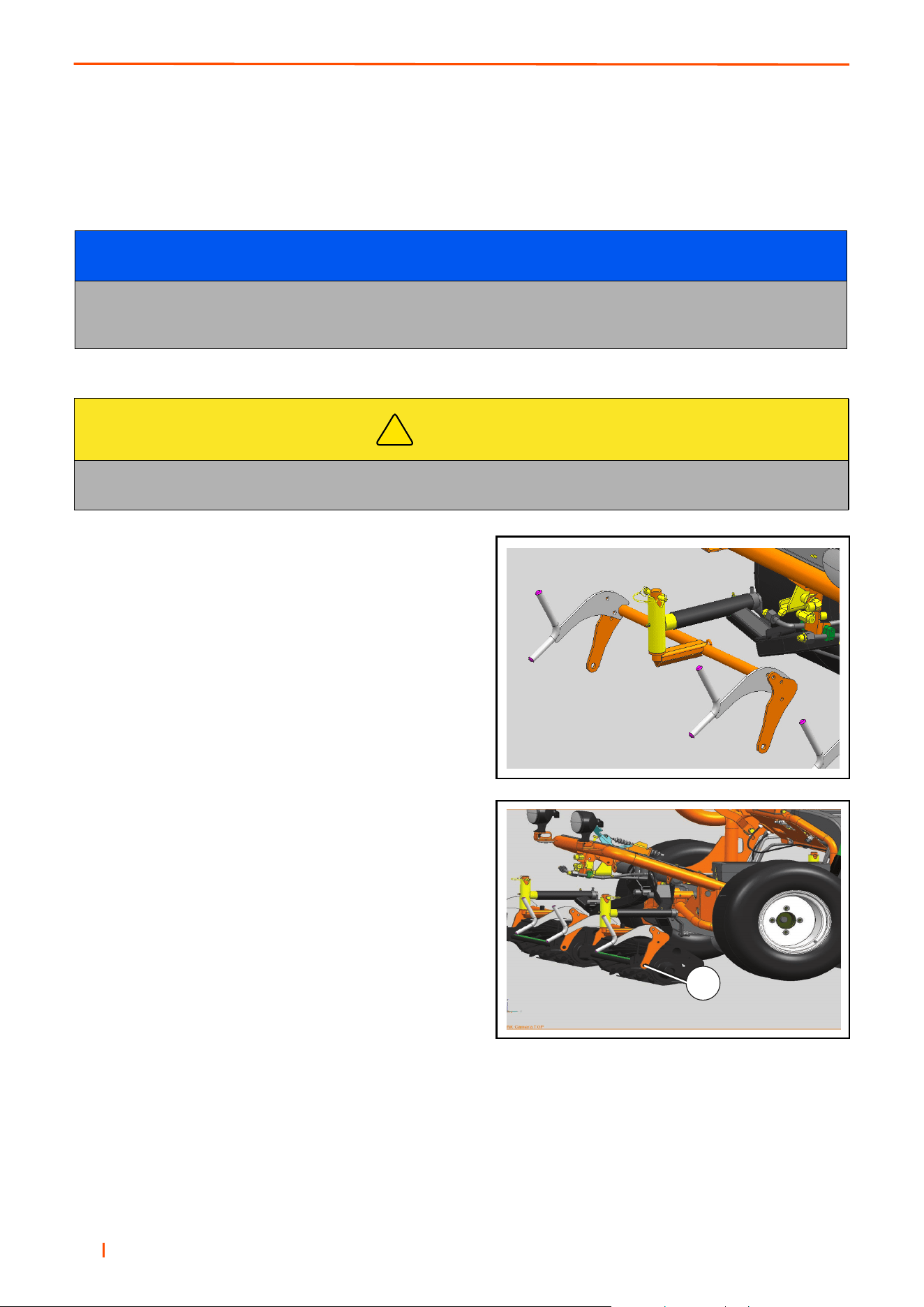
6.5 MOUNTING THE CUTTING HEADS_________________________________________
Review the “OPERATION” section before mounting the Cutting Units.
1. Cut all shipping straps holding the front pull frames in
place and position the pull frames so the up stop bum-
pers contact the up stop brackets. Set cutting head
drive motors and hoses away from the lift arms.
2. With the reel enable switch in the “OFF” position, lower
all three Cutting Unit lift arms and turn off the Unit and
remove ignition key.
3. Align the Cutting Unit at the front of the yoke frame.
Secure cutting head to either side of the yoke frame
using the shoulder bolt (A) on each side of the cutting
head.
4. To remove the Cutting Unit, undo shoulder bolts,
applied in step 3.
NOTICE
All Jacobsen Cutting Units are backlapped at the factory, but the Bedknife adjustment must
be performed before the unit is put into use. Refer to the Bedknife Adjustment Procedure as described
in section 8.8 & 8.13 in this manual.
CAUTION
Take care when handling the Cutting Units. Injury may result from contact with the sharp edges
of the reel blades.
!
A
B
en 41
OPERATION 6
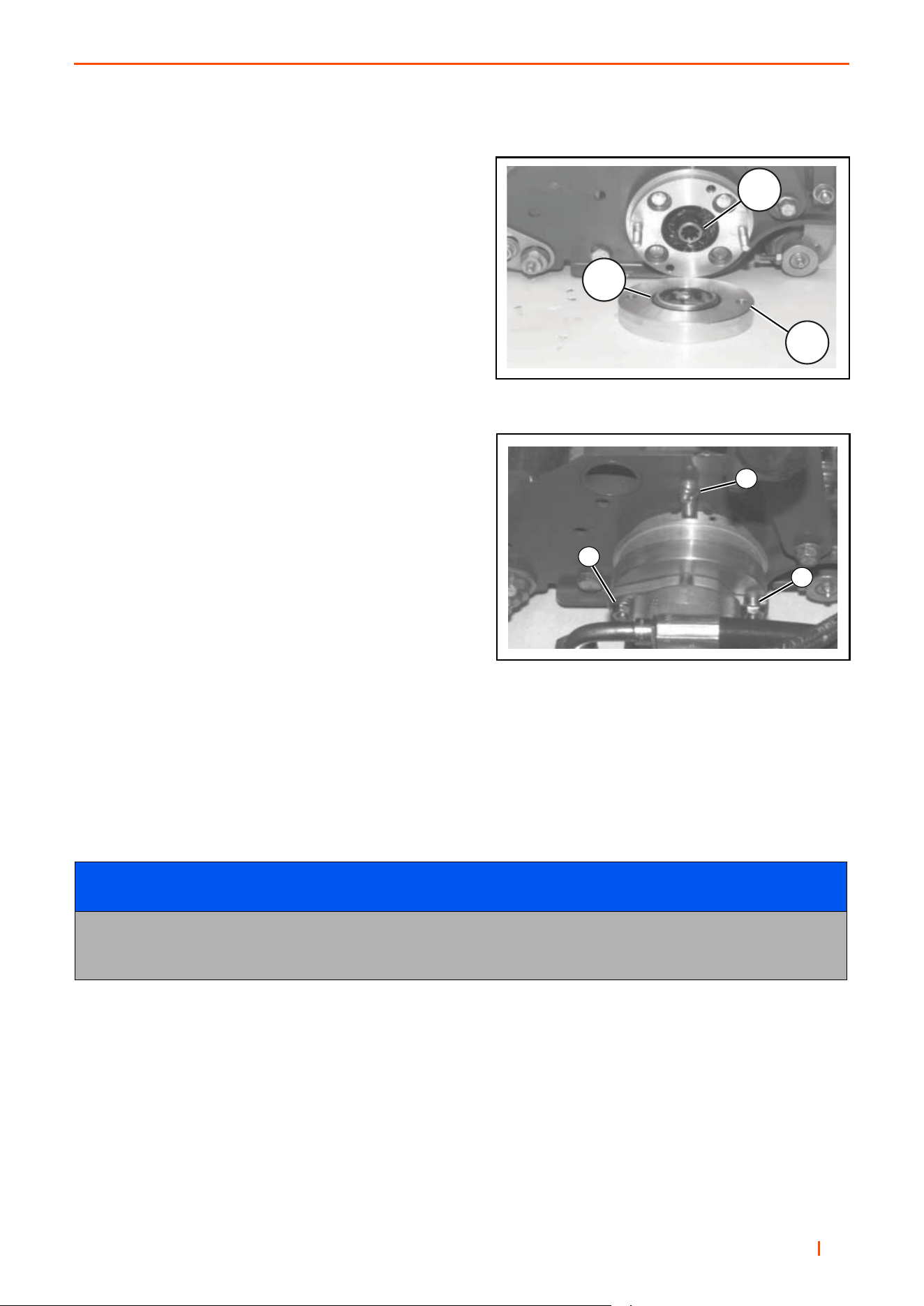
6.6 REEL MOTOR MOUNTING________________________________________________
1. The cutting head motor mounting adapter, coupling and
hardware are shipped in the step located above the left
front wheel. Install a 1.49" i.d. x 07" (38mm x 1.7mm) O-
ring on the male side of motor adapter plate and a 1.99"
i.d. x.07” (50mm x 1.7mm) O-ring on the reel motor
mount face.
2. Remove and discard screws holding the shipping cover
to cutting head (retain the shipping cover to protect the
bearings whenever the motor is removed from the
cutting head).
3. Install coupler (A) on cutting head shaft.
4. Install motor adapter plate (B) positioning the male face
and O-ring (C) toward the cutting head.
5. Install two (2) 5/16-18 x 1 1/2” screws (with washer and
lock washer) loosely into the mounting holes.
6. Align the splines on the motor shaft with the coupler (A)
and slide the motor into place rotating approximately
45° away from the mounting screws. With motor face
against adapter plate (B), rotate the motor mounting
flange into place engaging the screws into the motor
mounting flange slots. Tighten screws to 18ft/lbs
(24 Nm).
7. Add lithium based lubricant to the bearing housings at BOTH ends of the reels bearings at both ends are par-
tially packed with lubricant at the factory, but additional lubricant is required once assembled. Use a grease
gun to add lubricant until it starts to escape from the fittings. Wipe off any excess lubricant.
NOTICE
Check to MAKE SURE when the cutting heads are lowered to the turf, they must contact the turf evenly
across the entire length of the cutting head. If the front cutting heads contact the level surface unevenly,
refer to the adjustment section in the parts and maintenance manual.
Motor Mounting
Motor Mounting Screws & Lubricator
A
B
C
1
1
2
en 42
6 OPERATION
6.7 CUTTING CYLINDER LIFT & LOWER RATE & SYNCHRONISATION ______________
The valves that control the rate and sequence in which the
Cutting Units rise and fall are set at the factory, however they
can be reset or altered using the following steps.
1. Start the machine and run the engine at full throttle for
15-20 minutes to ensure that the oil is at the optimum
temperature.
2. To set up sequencing lift/lower of the front & rear unit.
Open all three valves fully. Screw the single front unit
adjuster (C) in until the rate of lift/lower is acceptable.
3. Use the two rear valves the upper valve (A) for lower
and the lower valve (B) for lift to provide the
sequencing of the Centre unit.
4. Cycle the cutting units to check the synchronisation.
The Centre Cutting Unit should lower and lift slightly
after the front Cutting Units.
If the cylinders drop too quickly or are not
synchronised correctly then they should be adjusted
accordingly.
The upper valve (A) at the rear of the machine adjusts
the rate at which the Centre Cutting Unit lowers.
The lower valve (B) at the rear adjusts the rate at
which the Centre Cutting Unit lifts.
The valve (C) under the operators seat adjusts the
rate at which the front Cutting Units lower.
5. If it is not possible to get the sequencing of the rear Cutting Unit correct this may be because the front
cutting units are set to lower too slowly. Try increasing the speed of drop slightly.
6. Once the Cutting Units are lifting and lowering correctly tighten each of the Grubscrews found on the valves
to lock the settings.
6.8 OPERATION OF THE MACHINE ___________________________________________
BEFORE OPERATING FOR THE FIRST TIME
• Check and adjust tyre pressure, if necessary, see section 3.2 Specification.
• Add fuel to the fuel tank if necessary.
• Check engine oil and top-up, if necessary.
• Check radiator coolant and top-up, if necessary (50% antifreeze solution).
• Make sure you understand the information contained in the previous sections.
Centre Unit Lift & Lower Valves
Front Unit Lower Valve
B
A
C

B
en 43
OPERATION 6
6.9 STARTING THE ENGINE _________________________________________________
The following procedure is for starting cold engines.
1. Ensure the FWD/REV pedal is in the neutral position, the mow switch is off, the throttle setting is in a mid
position.
2. Turn the ignition switch fully clockwise and hold until the engine starts (approximately 5-10 sec.)
3. The glow plugs are auto timed depending on the coolant temperature for operating the starter motor (This
should only take a few seconds)
4. When the engine starts, release the key immediately and it will return to the RUN position.
5. If the engine does not start, return key to the OFF position and try again.
NOTES:
• If the engine fails to start after two attempts, wait 20 seconds and try again.
• The starter motor should never be run continuously for longer than 30 seconds or it may fail.
• If the red LED’s on the display flash whilst starting one of the safety interlock switches has not been set
correctly.
6.10 DRIVING _____________________________________________________________
• Release brake - Make sure the parking brake is released before attempting to go forward or reverse.
• Forward - Gently depress the top A of the FWD/REV foot pedal to reach desired ground speed.
• Reverse - Gently depress the bottom B of the FWD/REV foot pedal to reach desired ground speed.
• To stop - Gently return the FWD/REV foot pedal to the neutral position.
• To hold the vehicle stationary on a slope it may be necessary to apply a certain amount of reverse traction.
NOTES:
• Use complete foot to operate both forward and reverse.
• Do not move pedal suddenly–always operate slowly and smoothly. Never move pedal violently from
forward to reverse or vice versa.
• Always keep foot firmly on the foot pedal–a too relaxed foot control may result in a jerky motion.
6.11 MOWING PROCEDURE_________________________________________________
NOTE: Always remove the flag and inspect the green before mowing. Remove debris or other objects that may
damage the reels and/or Bedknives. Operators should practice mowing in a clear area to become familiar with
raising and lowering the mowing heads. They should be aware that the centre cutting head raises and lowers
slightly later than the front ones, allowing the centre cut to begin and end at the same point as the two side cuts.
Practising will help the operator become proficient at starting and stopping each pass within a foot or two of the
edge of the green. Then only one final pass around the green will be required to finish the operation.
Several factors may determine the direction of the mowing pattern, sand traps or other hazards near the green,
trees etc that can restrict where turns are made. The terrain of the green may also be a factor, but if conditions
allow, always try to mow the green in a different direction than the last time it was mowed.
1. Stop the unit just before reaching the green. Make sure the reel enable switch is in the "ON" position and
the mow / transport lever is in position 1 (mow). Proceed onto the green at mowing speed and lower the
mowing heads as the front grass catchers cross the leading edge of the green. At the end of the pass, raise
the heads as the front grass catchers cross the trailing edge of the green.
2. Always make mowing passes across the green in a straight line. DO NOT start to make the turn for the next
pass until the rear wheel is completely off the green, this will eliminate the possibility of the tires tearing the
turf during the turn.
3. Each successive pass should overlap the previous one by two or three inches (51 or 76mm) (a painted

en 44
6 OPERATION
mark two or three inches (51 or 76mm) in from the outer edges of the two front grass catchers will help
align each overlapping pass).
4. After all of the straight passes have been made, make one final pass around the outer edge of the green.
This final pass should always be in the opposite direction from the last time the green was mowed.
5. With the engine stopped or the reel enable switch in the "OFF" position, empty the grass catchers before
proceeding to the next green.
6.12 HOW TO STOP THE ENGINE_____________________________________________
1. Disengage drive to the Cutting Units with the Cutting Unit Switch.
2. Return the FWD/REV pedal to the neutral position.
3. Set the parking brake.
4. Move the throttle control lever to the SLOW position.
5. Turn the ignition key to OFF
6.13 HOW TO REMOVE A BLOCKAGE FROM CUTTING UNITS ____________________
1. Disengage the power to the cutting units with the cutting unit switch.
2. Keep the cutting units lowered to the ground (Wait for the remaining cutting cylinders to stop rotation).
3. Lift the cutting units into the “Transport Position”, lock in position use the transport latches fitted on your product.
4. Remove your foot from the forward/reverse pedal.
5. Set the parking brake.
6. Move the throttle control lever to the slow position.
7. Turn the ignition key to the off position and remove the key
NOTICE
To avoid damage to the green, NEVER stop the forward motion of the mower on the green with the reels
turning. Stopping the mower on a wet green may cause wheel indentations.
CAUTION
It is important to note: there will be remaining hydraulic pressure within the system that can cause
the cutting cylinder to rotate when the obstruction is removed. Therefore keep your hands, feet
and clothing away from Cutting Units at all times.
NOTICE
Make sure correctly selected PPE is worn before you clear the obstruction.
!

B
en 45
OPERATION 6
8. Use the Jacobsen “Cutting Unit Tool” part number 4184540 See below or stout stick, put into the cutting
cylinder between the blades
9. Rotate the cylinder with either the “Cutting Unit Tool” or “Stout Stick” until the obstruction has been removed.
10. Inspect all the cutting surfaces for damage, when necessary replace the damaged components.
6.14 BACKLAPPING_______________________________________________________
This mower is fitted with the ability to allow the reels to be driven in reverse for backlapping.
• Backlapping is a process which will lightly grind the reel to the bedknife whilst mounted on the mower.
• If significant amounts of metal are to be removed then the cutting unit should be reground on a specialised
grinding machine.
• Before any backlapping is carried out, Ransomes Jacobsen recommends that the backlapping process
should be risk assessed as a workshop process by the manager of the machine.
• Backlapping should only be carried out by trained staff.
• Ransomes Jacobsen recommend that grinding paste is only applied to the reel when it is stationery, the
engine is off and the parking brake applied.
• When applying grinding paste the reel should only be rotated by appropriately sized piece of wood and not
by hand.
• Place reels in the most accessible position for applying the paste.
• After applying the grinding paste the person backlapping should return to the seat, engage the relevant
controls and run the reels in reverse.
• When the desired finish is achieved switch off the mower, clean off any surplus paste, reset the reel to
bedknife and return the controls to the normal mow positions.
Jacobsen grinding paste:
Grinding Paste
Part Number
80 grit grinding paste, 4.5kg tin
5002488
120 grit grinding paste, 4.5kg tin
5002489
80 grit grinding paste, 9kg tin
5002490
120 grit grinding paste, 9kg tin 5002491
en 46
6 OPERATION
6.15 BACKLAPPING PROCEDURE____________________________________________
Before starting the backlap procedure, release the Centre Unit and swing it out. The backlap valve is located
under the seat plate on the right hand side. It can be accessed from under the machine when the Centre Unit
is swung out
1. Apply an even coat of backlapping compound to the entire length of each blade of the reels.
2. While pressing the centre red button (A) on the reel valve pull yellow plunger (B) away from the valve.
3. Start the engine and set the throttle to low idle. Lower heads by operating the Joystick or paddle.
4. Slowly turn the restriction valve knob (C) clockwise until the desired reel rotation speed is attained. It should
be slow enough so that the reel will not throw off the backlapping compound as it spins.
5. Once all the blades on the reel are uniformly sharp, shut off the engine and push yellow plunger (B) back
towards the valve. Set the reel speed valve (C) to mow speed.
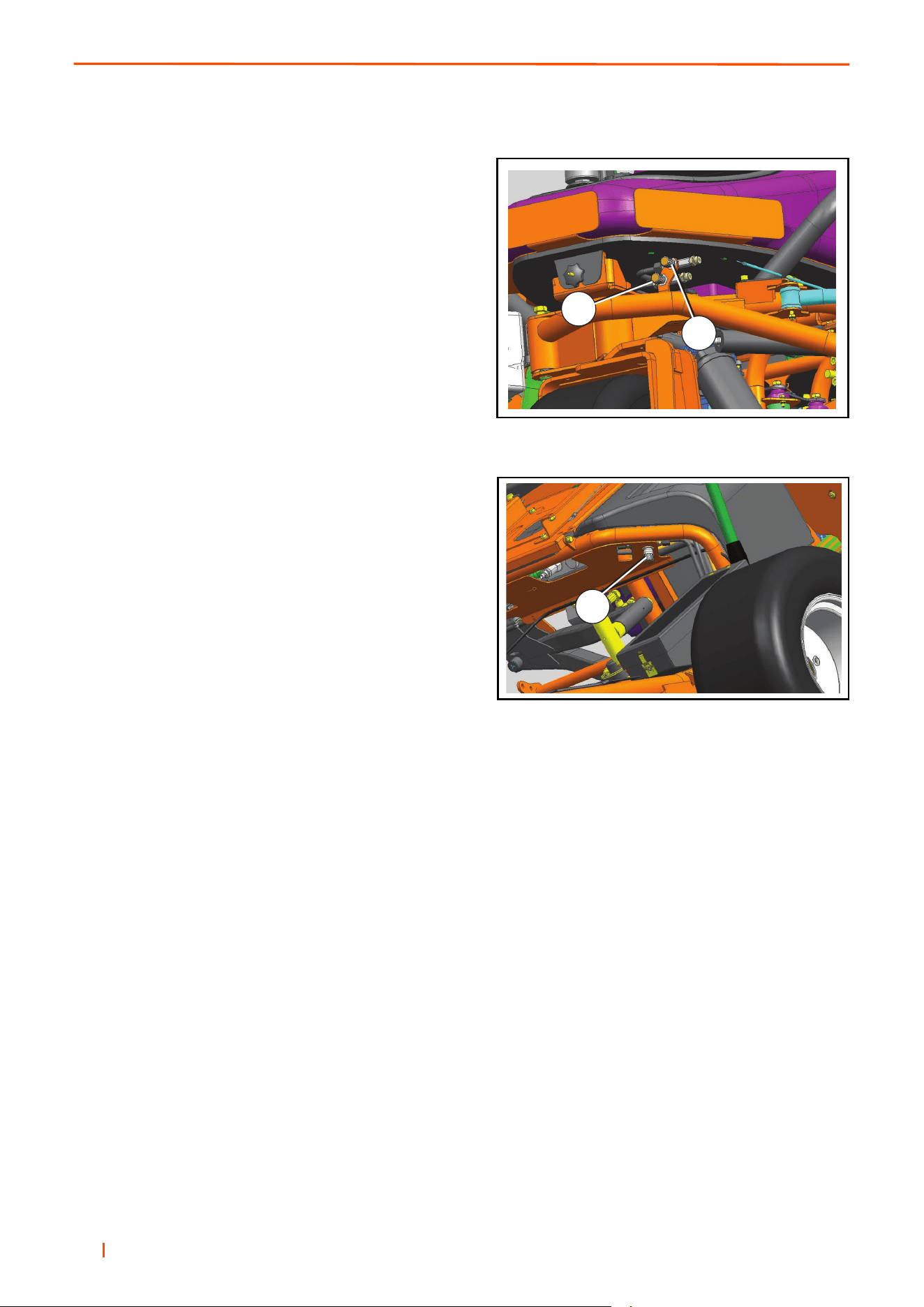
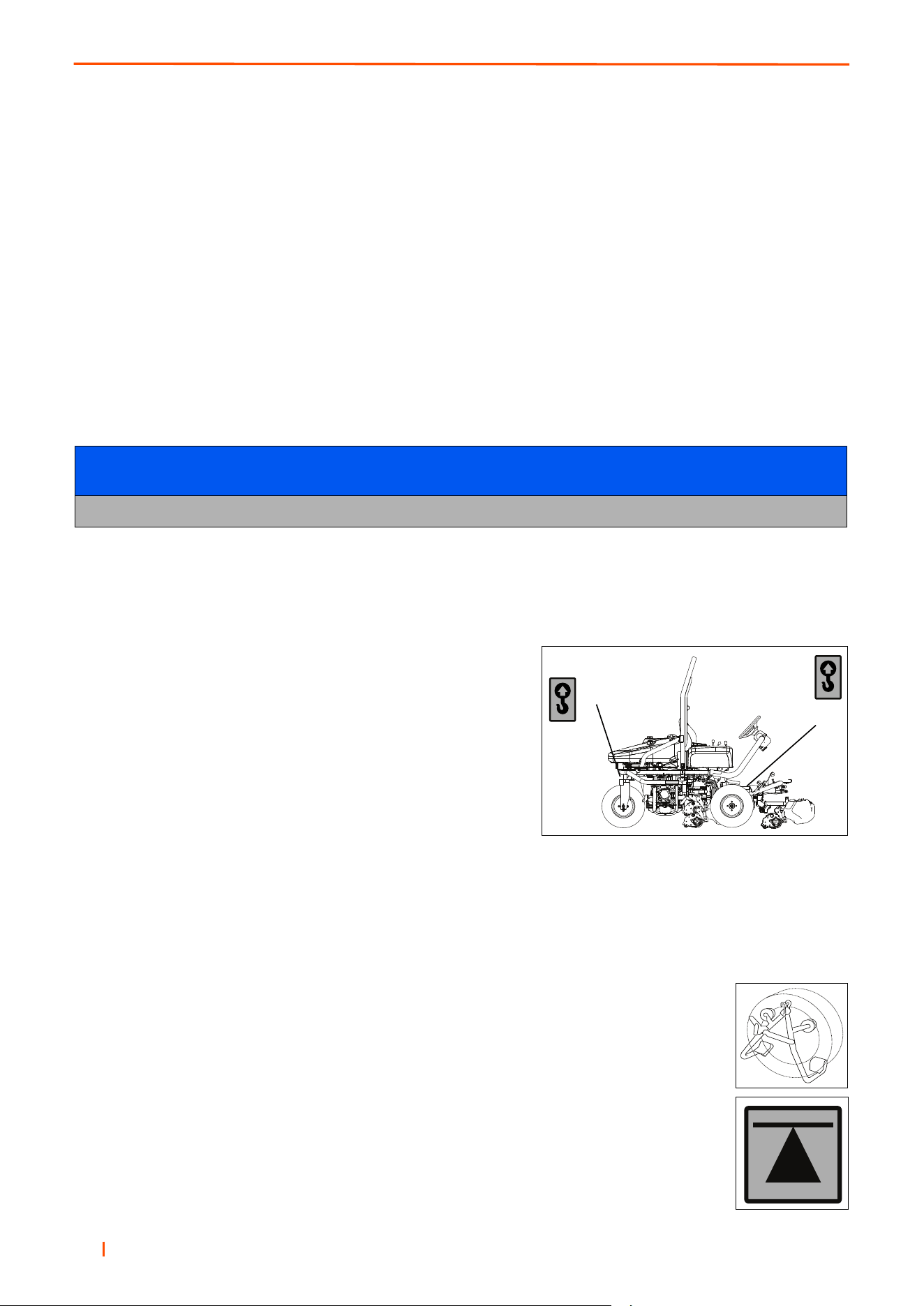
6.16 TRANSPORTING ON A TRAILER OR FLATBED _____________________________
The machine has hard-point tie-down loops front (A) and rear (B). Fasten the mower to the transport vehicle.
Make sure that all tie down straps are tight. Make sure that the
decks are locked in the transport position. Check the fuel and
hydraulic tank caps are tight. Make sure that no part of the mower
can fall during transport.
Always follow the given maximum transport load weight for the
vehicle used.
DO NOT carry more than the maximum weight shown on the
transport vehicle plate.
Always read the safety and operation manual of the transport vehicle before you load.
6.17 SLINGING AND JACKING THE MACHINE __________________________________
Slinging
When slinging the machine use the tie down loops front and rear.
Jacking
The machine has three jacking points, one at the rear chassis engine mount and two on
the front chassis wheel motor mounting.
NOTICE
To ensure proper reel rotation, make sure valve (C) is completely closed.
A
B
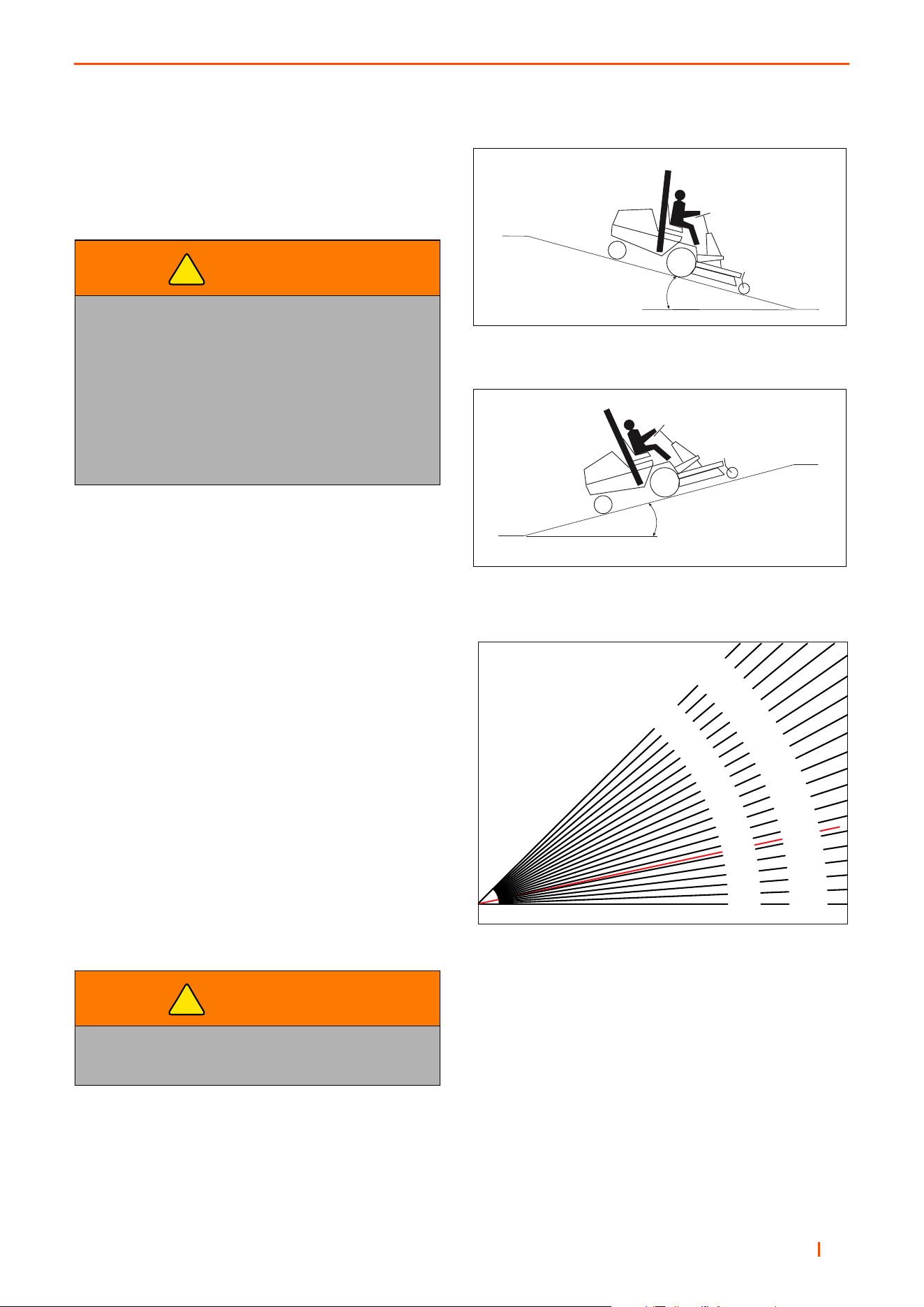
B
en 47
OPERATION 6
6.18 MOWING ON SLOPES __________________________________________________
The mower has been designed for good traction and
stability under normal mowing conditions. Use caution
when operating on slopes, especially when the grass is
wet. Wet grass reduces traction and steering control.
1. Always mow with the engine at full throttle, control
forward speed using traction foot pedal to maintain
proper cutting.
2. Use weight transfer control as required to improve
weight distribution between decks and mower.
3. If the mower tends to slide or the tyres begin to mark
the turf, angle mower into a less steep slope until
traction is regained or tyre marking stops.
4. If mower continues to slide or mark the turf, the slope
is too steep for safe operation. Do not make another
attempt to climb, and back down slowly.
5. When descending a steep slope, always lower
implements to the ground to reduce the risk of
mower overturning.
Correct tyre pressure is essential for maximum
traction. See 3.2 Specification.
WARNING
To minimize the possibility of overturning, the
safest method for operating on hills and
terraces is to travel up and down the face of
the slope (vertically), not across the face
(horizontally). Avoid unnecessary turns, travel
at reduced speeds, and stay alert for hidden
hazards. To ensure best stability always load
the left hand storage rack first and cut with all
three units powered.
WARNING
DO NOT USE ON SLOPES GREATER
THAN 16°
!
!
XX° Maximum
XX° Maximum
A = Maximum Allowable Slope
A = Maximum Allowable Slope
0°
0%
2-3/4°
5%
5-3/4°
10%
8-1/2°
15%
11-1/4°
20%
14°
25%
16-3/4°
30%
19-1/4°
35%
21-3/4°
40%
24-1/4°
45%
26-1/2°
50%
28-3/4°
55%
31°
60%
33°
65%
35°
70%
36-3/4°
75%
38-3/4°
80%
40-1/4°
85%
42°
90%
43-1/2°
95%
45°
100%
Degrees
Grade
General slope of roadway embankment - 45°
Steepest grass area - 31°
Slope of average roof - 19.25°
2nd class highway maximum grade 4.5°
Toll road or freeway - 1.75°
Degrees are shown to the nearest 1/4”.
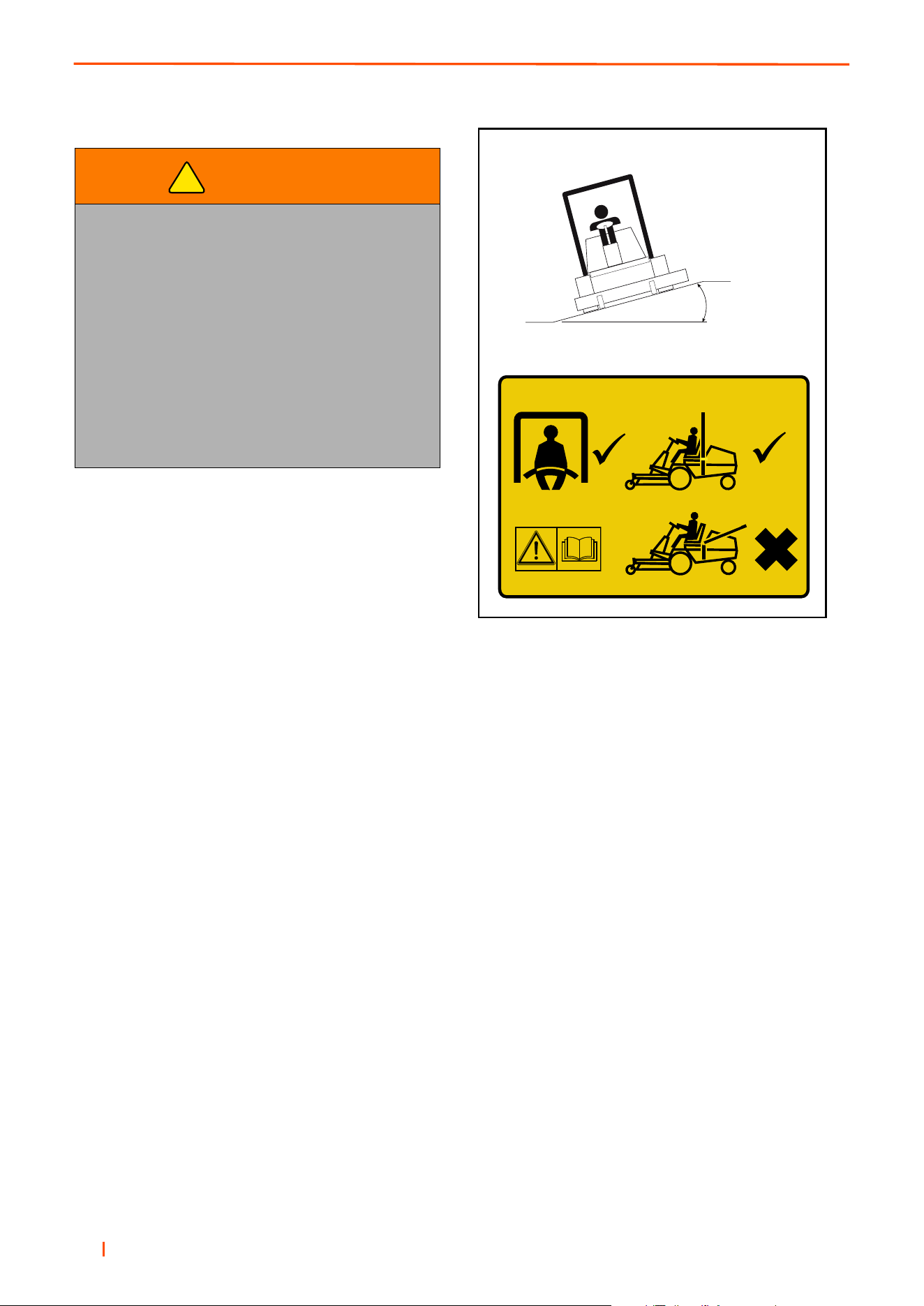
en 48
6 OPERATION
WARNING
When the machine is being used, whether
cutting grass or not, on slopes, the ROPS
frame should be deployed and the seat belt
used. This rationale is based on the fact that
a seat belt must be worn with a ROPS to
comply with the Machiney Directive
2006/42/EC Sections 3.2.2, Seating & 3.4.3,
Rollover
Ransomes Jacobsen Limited recommends that
a local risk assessment is completed by the
owner/user of the machine to determine the risks
associated with working on slopes.
!
A

en 49
OPERATION 6
NOTES

en 50
7 MAINTENANCE
7.1 MAINTENANCE & LUBRICATION CHART _________________________________
MAINTENANCE & LUBRICATION CHART
Interval Item
First 50 hours
Change Engine Oil & Filter.
Check Fan Belt Tension.
Change Hydraulic Oil Filter.
Daily
10 hours
Check Engine Oil Level.
Check Safety Interlock System.
Check Engine Coolant Level
Check Hydraulic Fluid Level
Check Tyre Pressure.
Check Air Filter Tell Tail Indicator*.
Check for Hydraulic Leaks.
Check Oil Cooler Screen.
Check Oil Cooler Fins.
Check Bedknife & Reel Blades.
Walk-Around Inspection.
Weekly Every 50 hours
Check for Loose Components.
Check Fan Belt Tension.
Check Engine Bay For Debris.
Check Battery Condition.
Fuel Tank Water and Sediment - Drain.
Every 100 hours
Change Engine Oil Filter.
Check Fuel Filter For Water Contamination.
Every 200 hours
Change Engine Oil.
Change Inline Fuel Filter.
Every 250 hours
Change Hydraulic Oil & Filters.
Alternator and Fan Belts - Inspect / Adjust.
Every 500 hours
Change Air Filter Element*.
Change Oil and Filter Element.
Check Safety Interlock System.
Hoses and Clamps - Inspect / Replace.
Radiator - Clean
End of season
Every 1000 hours
Check Parking Brake Operation.
Check Brake pads.
Drain & Clean Fuel Tank
Drain & Replace Engine Coolant
Lubricate all Grease fittings weekly
A = Lift Arm Pivot, B = Cutting Unit Pivot, C = Cutting Unit Bearing Housing, D = Steering Ram Ball Joint.
*Check more often in dirty conditions
IMPORTANT
Refer to Engine Manufacturers Manual for Additional Engine Maintenance Procedures
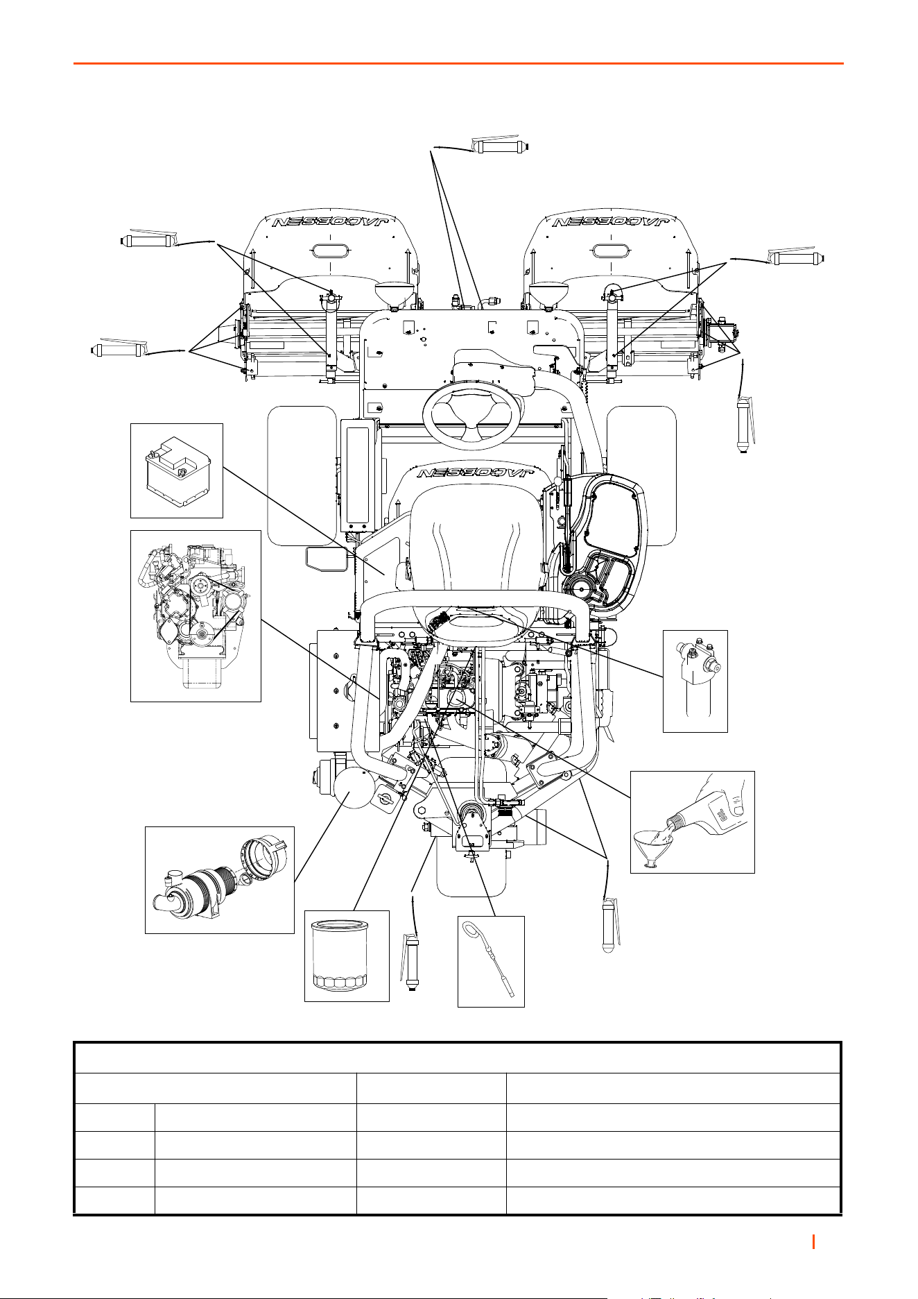
B
en 51
MAINTENANCE 7
Fluid Requirements
Quantity Type
A Engine Oil (with filter) 3.0 litres SAE10W 30
B Hydraulic Oil (with filter) 23 litres GreensCare ISO VG 46
C Radiator Coolant 4.4 litres 50% Anti-Freeze
D Fuel 55 litres No 2-D (ASTM D975) Diesel

en 52
7 MAINTENANCE
7.2 ENGINE ACCESS _____________________________________________________
The Fuel & Hydraulic Tanks can be raised for better access to the engine.
a. Tilt the seat forwards.
b. Turn fuel tap OFF (C) (Gasoline machines only)
c. Loosen the locking hand wheel (A), under the tank
above the rear axle.
d. Raise the tanks.
Support the tanks by pivoting the stay (B) beneath the
tank and secure in the hole provided.
Engine Oil: Must meet A.P.I. CK-4
TEMPERATURE VISCOSITY
-18°C to 40°C (-0.4°F to 104°F) SAE10W-30
WARNING
Never operate the equipment with the
operator presence & safety interlock system
disengaged or malfunctioning.
Do not disconnect or bypass any switch.
CAUTION
When raising the tanks have a second person
available to locate the stay in the hole provided.
!
!
Lifting The Tank
B
A
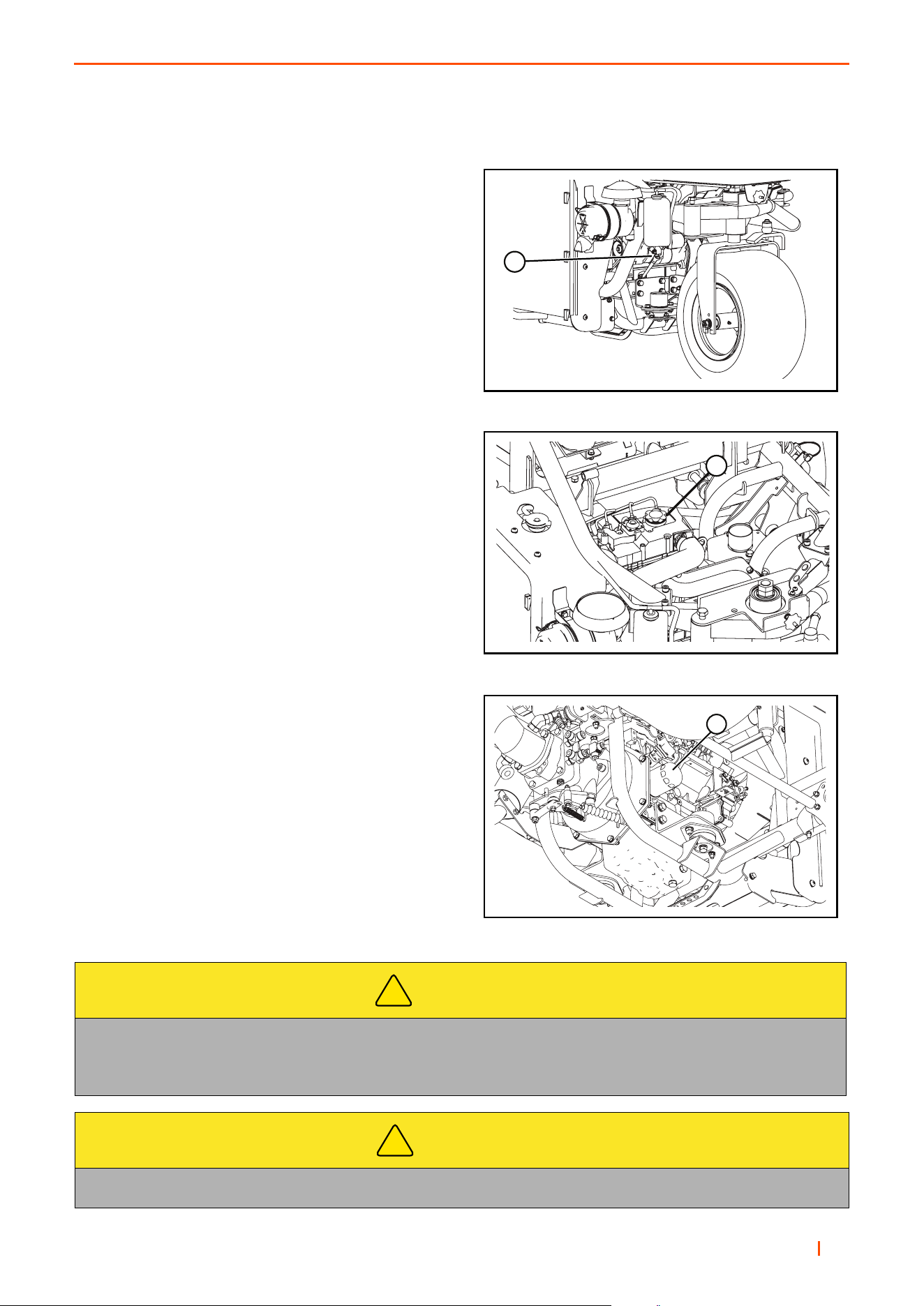
B
en 53
MAINTENANCE 7
7.3 ENGINE LUBRICATION ________________________________________________
Check Engine Oil Level
Check the engine oil level before starting or more than five
minutes after stopping the engine.
(a) With the machine on level ground, remove the
dipstick 1, wipe it clean and replace.
(b) Take the dipstick 1 out again, and check the oil
level. It should be between level marks on dipstick.
Change Engine Oil
(a) Warm up the engine first and then shut it off.
Remove oil drain plug from the bottom of the
crankcase and wipe it off.
(b) Drain engine oil in to a suitable container.
(c) Replace the drain plug and fill engine with the
correct quantity & grade of oil through the filler (2).
Change Engine Oil Filter
(a) Remove single-unit cartridge (3)
(b) Collect engine oil in a suitable container.
(c) Clean area on crankcase.
(d) Apply thin coat of oil to cartridge gasket
before installing.
(e) Tighten filter by hand only.
(f) Check for oil leaks around the cartridge gasket after
engine is started.
CAUTION
Contact with engine oil can damage your skin. Use gloves when working with engine oil.
If you come in contact with engine oil, wash it off immediately.
Dispose of used engine oil in accordance with local regulations.
CAUTION
Dispose of used engine oil in accordance with local regulations.
!
!
1. Oil Filler Port
1. Dipstick
1. Oil Filter
1
2
3
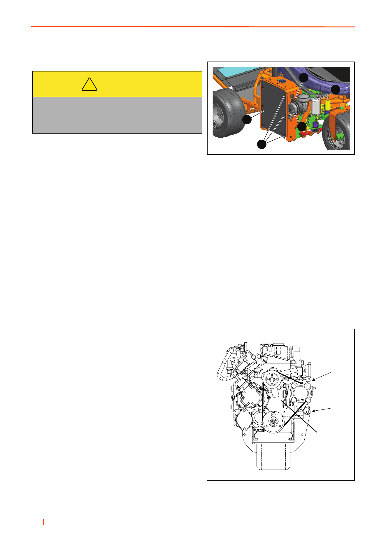
en 54
7 MAINTENANCE
7.4 AIR FILTER __________________________________________________________
Clean Air Filter Element
1. As the element of the air cleaner employed on this
engine is a dry type, never apply oil to it.
2. Open the evacuator valve once a week under ordinary conditions-or daily when used in dusty conditions to
get rid of large particles of dust and dirt.
3. Avoid touching the element except when cleaning.
4. When dry dust adheres to the element, blow compressed air from the inside turning the element. Pressure
of compressed air must be under 7kgf/cm2 (100psi). Wear the appropriate personal protective equipment
5. When carbon or oil adheres to the element, soak the element in detergent for 15 minutes then wash it
several times in water, rinse with clean water and dry it naturally. After the element is fully dried, inspect
inside of the element with a light and check if it is damaged or not. (referring to the instructions on the label
attached to the element.)
7.5 ENGINE: FAN BELT ___________________________________________________
Check & Adjust Fan Belt
The fan belt is adjusted so that it has sufficient tension to
avoid undue stress on alternator bearings but does not slip
on the alternator pulley. Use the following procedure to
check the belt tension at the mid-point of the belt between
crank shaft and alternator pulleys.
1. Loosen alternator bolt (A) and pivot bolt (B) on the
underside of the alternator.
2. Move the alternator to tighten or loosen the belt so that a
deflection of 7 to 9 mm is achieved at the mid-span with a
load 10Kgf (98N/22lbs).
3. Re-tighten bolts.
CAUTION
Check the air filter condition indicator situated on the un-
derside of the outlet elbow at regular intervals. If the indi-
cator shows red either clean or replace the air filter
element.
!
A. Cover, B. Evacuator valve
A
B
C
D
E
A
B
7 - 9mm
0.28 - 0.35in
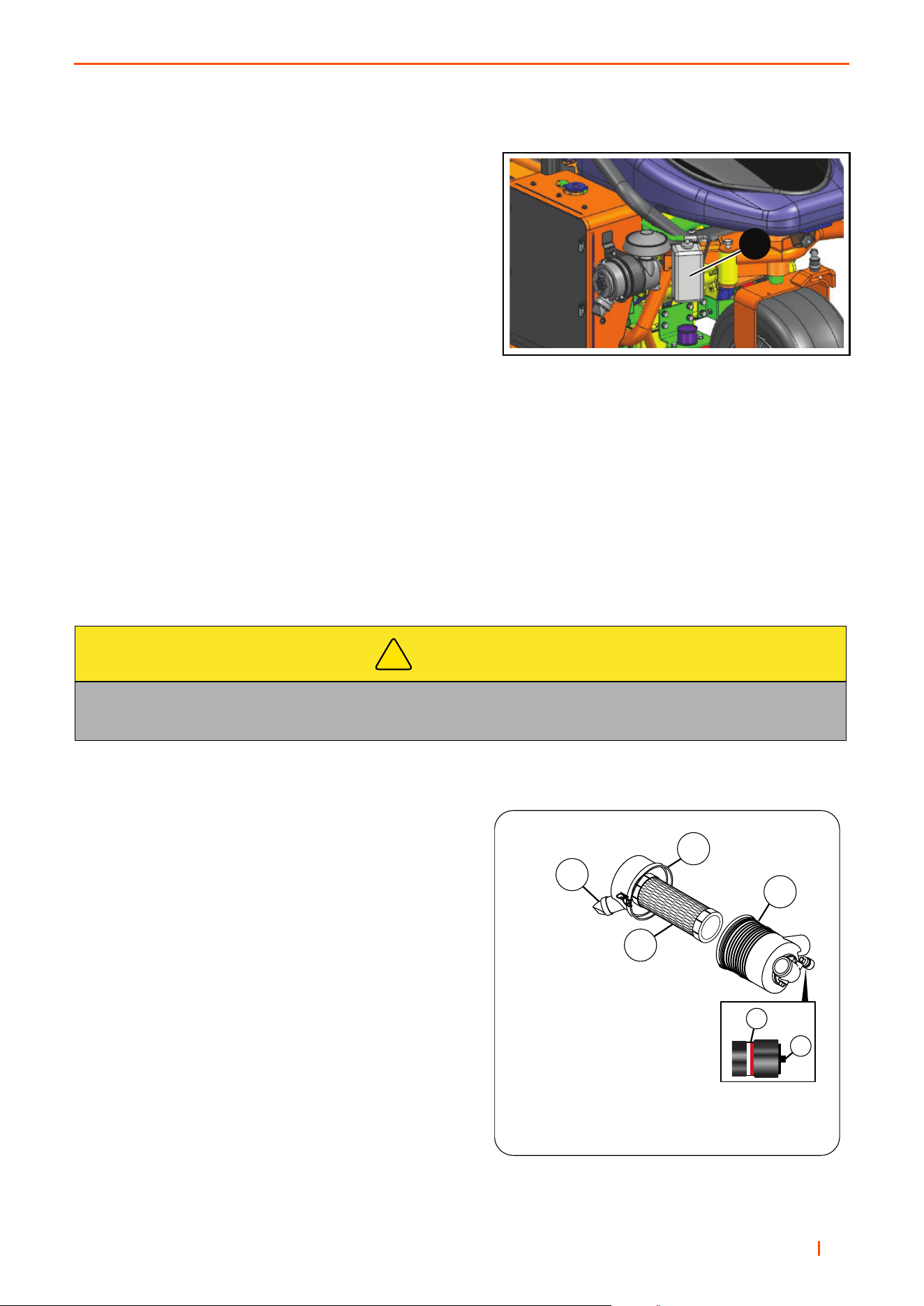
B
en 55
MAINTENANCE 7
7.6 ENGINE COOLANT ___________________________________________________ _
Check Engine Coolant Level
1 To prevent injury from the hot engine coolant or steam,
never remove the radiator cap with the engine in
operation. Stop the engine and wait until the radiator is
cool. When radiator is cool, use caution to remove the
radiator cap.
2 If water change is needed, remove the drain plug
located at the bottom right side of the radiator.
3. The level of coolant in the expansion tank (C) should
be between the MAX and MIN level indicators
when cold.
4. If topping up is required, remove the plastic cap and top up using the correct anti-freeze mixture.
5. Replace the plastic cap when finished.
Changing Coolant
1. To drain coolant, remove hose from radiator.
2. Replace hose back on to radiator. Ensure all hose clips are tight.
3. Refill the cooling system with the correct anti-freeze mixture. Fill system through expansion tank.
4. The level of coolant in the expansion tank should be between the MAX and MIN level indicators when cold.
5. Run the engine for approximately 5 minutes or until the thermostat opens.
6. Check level of coolant in expansion tank and top up if necessary
7.7 AIR CLEANER _______________________________________________________
Check the service indicator (F) each day. If the red band
become visible in the window, replace the filter elements.
Check the dust valve (A) each day by pressing the valve
together allowing any dust particles to fall out of the air
cleaner cover.
Unnecessary removal of the elements to inspect or clean
increases the risk of dust and other particles to enter the
engine.
When service is needed, first clean the outside of the filter
housing, then remove the old primary (C).
Clean the inside of the filter housing. Make sure dust and
other particles do not get into the engine inlet hose.
Inspect the new elements. Do not use a damaged element
and never use an incorrect element.
Make sure the element is seated correctly. Press the button
to set the service indicator.
Assemble the cap (B) to the filter housing (E). Make sure
the cap seals around the filter housing. The dust valve on
the cap must be at the bottom of the filter. Fasten the cap
with the two clips.
Check the air filter hoses for wear or damage. Make sure the hose clamps are tight and hold the hoses in position.
CAUTION
Contact with Anti-freeze can damage your skin. Use gloves when working with Anti-freeze.
If you come in contact with Anti-freeze, wash it off immediately.
!
B
D
F
G
A
C
A – Dust Valve
B – Air Filter Cap
C – Primary Filter Element
D – Air Filter Housing
F – Service Indicator
G – Service Indicator Reset Button
C
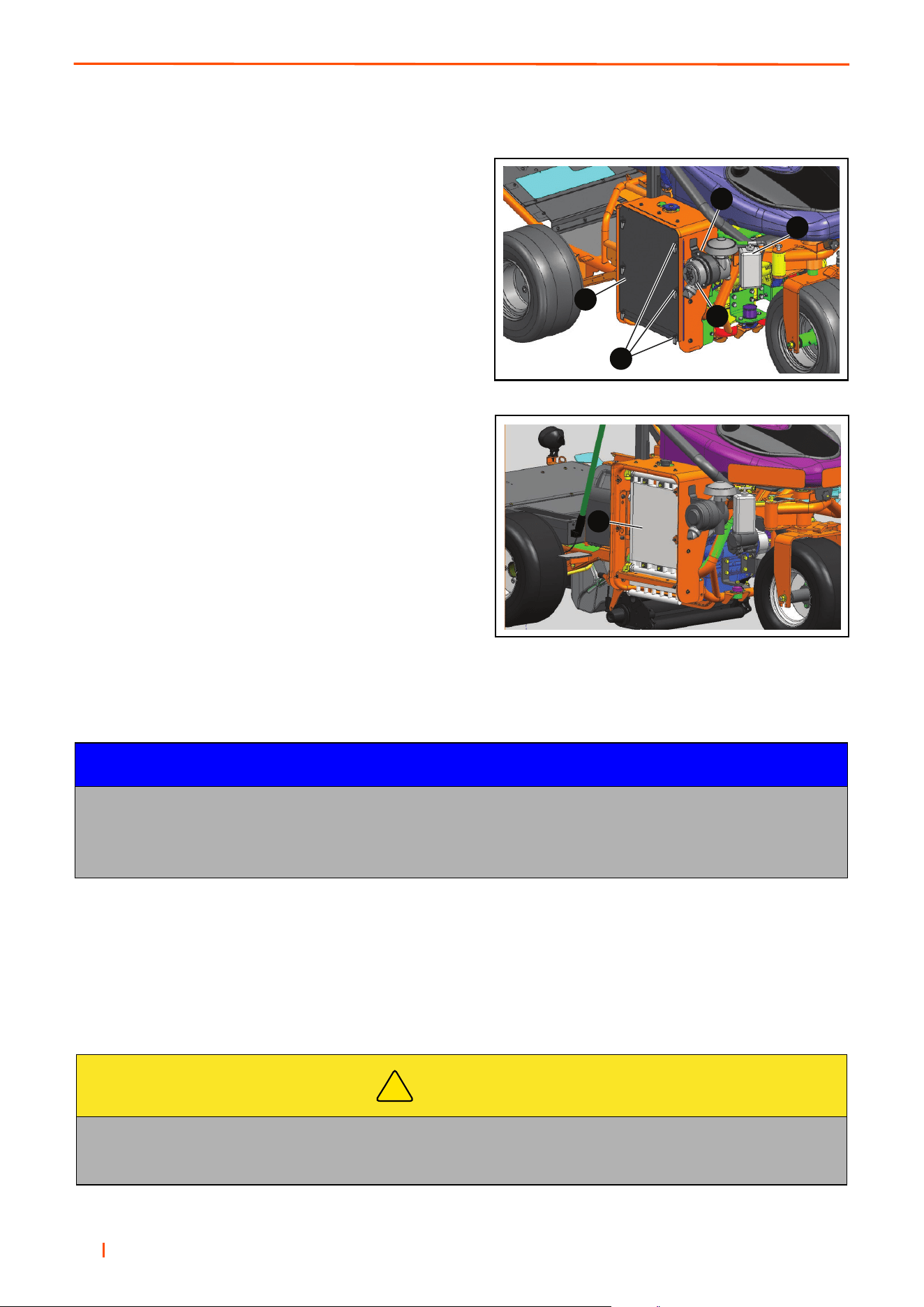
en 56
7 MAINTENANCE
7.8 OIL COOLER AND RADIATOR __________________________________________
1. Release the 6 Swell latches (D) holding the radiator
/ oil cooler mesh cover (E) to the cowling.
2. Remove screen and clean.
3. Remove any debris from inside of cowling and around
oil cooler and radiator F.
4. Replace screen, secure with swell latches.
7.9 PRIME THE FUEL SYSTEM _____________________________________________
Use the following procedure to prime the fuel system:
If air enters the fuel system, the air must be purged from the fuel system before the engine can be started. Air can
enter the fuel system when the following events occur:
• The fuel tank is empty or the fuel system has been partially drained.
• The low-pressure fuel lines are disconnected.
• A leak exists in the low-pressure fuel system.
• The fuel filter is replaced.
NOTICE
Care must be taken to ensure that fluids are contained during performance of inspection, maintenance,
testing, adjusting and repair of the product.
Be prepared to collect the with suitable containers before opening any compartment or disassembling
any component containing fluids.
CAUTION
Contact with diesel fuel can damage your skin. Use gloves when working with diesel fuel.
If you come in contact with diesel fuel, wash it off immediately.
Dispose of used diesel fuel in accordance with local regulations.
!
A
B
C
D
E
F
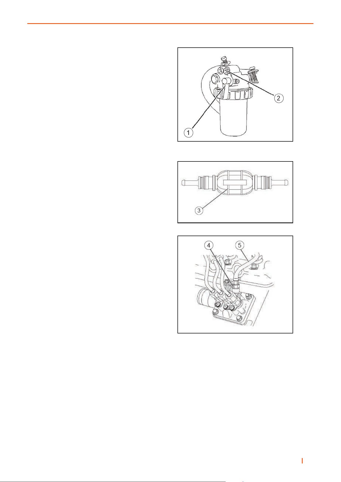
B
en 57
MAINTENANCE 7
Secondary Fuel Filter
Fuel filter that is installed on the engine.
Element
(1) Fuel valve
(2) Vent screw
In-line Priming Pump
1. Ensure that the fuel valve for the fuel filter that has
an element is in the ON position (1).
2. Loosen vent screw (2).
3. Operate in-line priming pump (3). When fuel free
from air flows from the vent screw tighten the
vent screw.
4. Loosen connection (4) at the fuel injection
pump.
Note: Fuel return line (5) may need to be removed
to prime the fuel system.
5. Operate the in-line priming pump. When fuel is
free from all air flows from the connections tighten
the connecting bolt.
6. The engine should now be able to start. Operate
‘the starting motor to start the engine.
Note: Do not operate the starting motor for more than
15 seconds. If the engine does not start after 15 sec-
onds, stop and wait for 30 seconds before trying again.
Secondary Fuel Filter
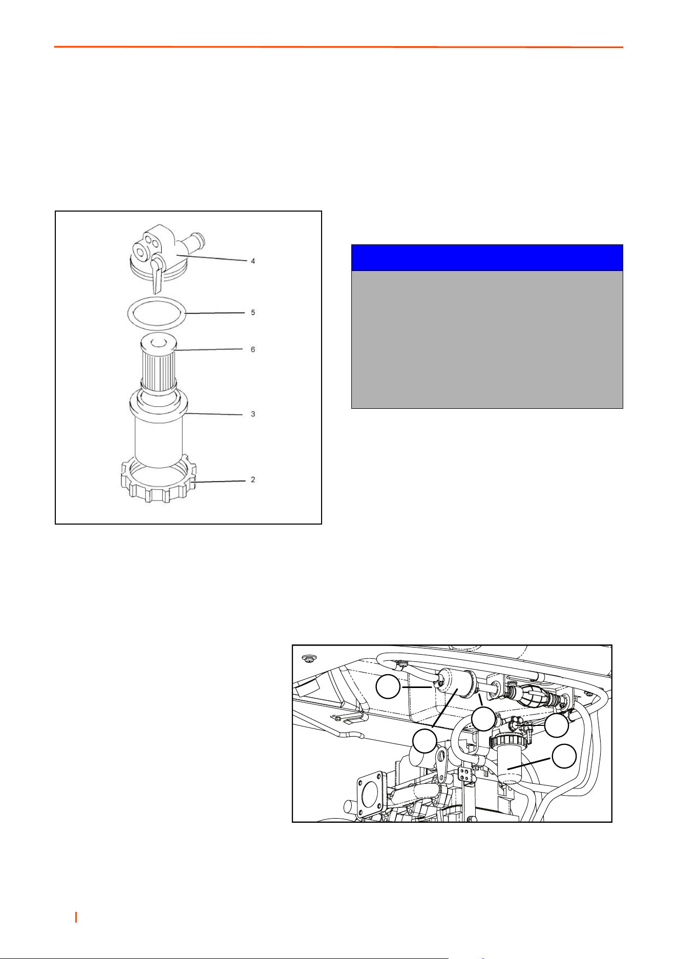
en 58
7 MAINTENANCE
Replacing Secondary Fuel Filter
1. Clean the outside of the fuel filter assembly.
2. Loosen locking ring (2).
3. Remove the casting for the filter (3) and the
element. Ensure that any fluid is drained into
a suitable container.
4. Assemble the following items: seal (5), filter
element (6) and casing (3).
Note: Do not fill the fuel filter with fuel. This fuel will
not be filtered and the fuel could be contaminated.
Contaminated fuel can damage the fuel system.
5. install the assembled items to the filter base (4).
6. Install the locking ring (2) to the filter base. Rotate
the locking ring in order to lock the assembly.
The fuel system will need to be primed after the new
filter is installed.
NOTICE
Care must be taken to ensure that fluids are
contained during performance of inspection,
maintenance, testing, adjusting and repair of
the product.
Be prepared to collect the fluid with suitable
containers before opening any compartment or
disassembling any component containing fluids.
Dispose of all fluids according to local regulations
and mandates.
7.10 REPLACING FUEL FILTERS ___________________________________________
1. Stop the engine.
2. Open the air valve (A) at the top of the
filter (B) to release system pressure.
3. Remove fuel filter cartridge (B). Clean
any fuel that spills.
4. Assemble new filter cartridge to the
filter base. Tighten the cartridge with
your hand.
5. Loosen hose clamps (C). Loosen filter
clamp (E) and replace pre-filter (D).
6. Bleed air from the fuel system - Close
Air Valve (A).
E
D
C
B
A
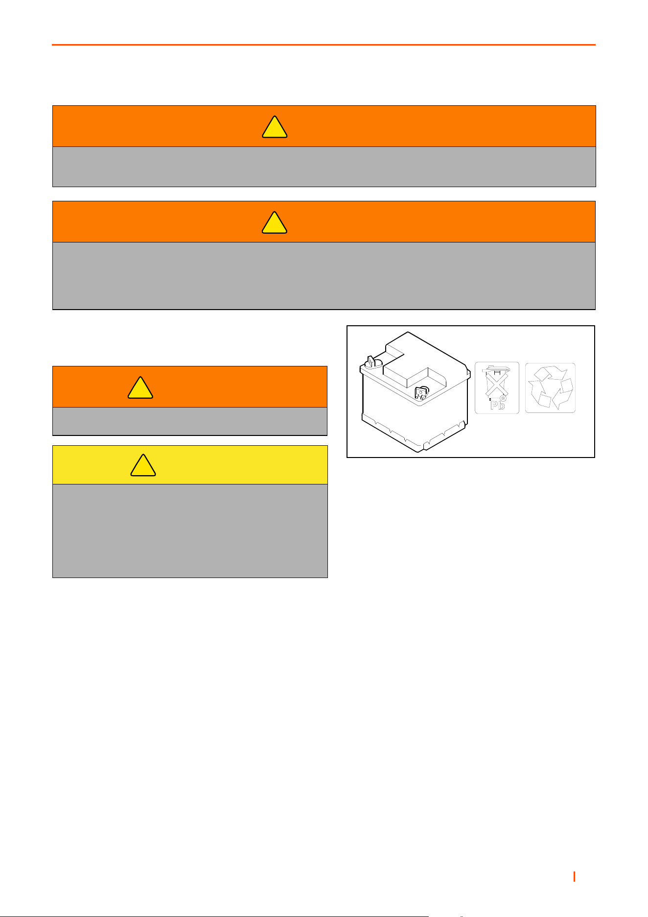
B
en 59
MAINTENANCE 7
7.11 BATTERY___________________________________________________________
1. Keep fluid levels above battery plates.
2. Keep battery post corrosion free
WARNING
Batteries produce explosive gases and contain corrosive acid and supply levels of electrical
current high enough to cause burns.
WARNING
Batteries produce explosive gases and contain corrosive acid and supply levels of electrical
current high enough to cause burns.
Battery posts, terminals and related accessories contain lead and lead compounds.
ALWAYS WASH HANDS AFTER HANDLING.
WARNING
Wear eye protection when servicing battery.
CAUTION
To help prevent injury, always wear safety glasses,
safety footwear, a hard hat and ear protection whilst
working on machinery.
Dispose of used batteries in accordance
with local regulations.
!
!
!
!
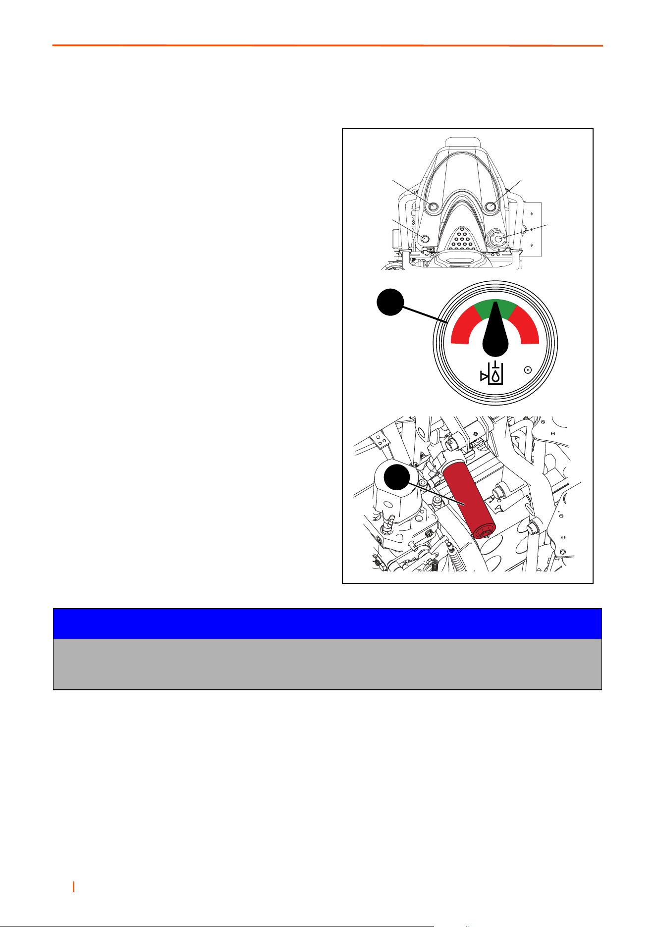
en 60
7 MAINTENANCE
7.12 HYDRAULIC SYSTEM ________________________________________________
Check Hydraulic Oil Level
Check hydraulic oil level using sight gauge (C).
Change Hydraulic Oil
1. Clean around hose in bottom of Hydraulic tank and
remove.
2.) Allow tank to drain into a suitable container and
replace hose.
3. Refill tank with the correct quantity and grade of
Hydraulic Oil through the filler cap. (D).
Change Hydraulic Oil Filter
(a) Wipe filter canister (A) and housing to remove any
dirt present.
(b) Place a suitable drip tray under the filter.
(c) Unscrew filter cannister and dispose of internal filter
element safely.
(d) Replace with new internal filter.
(e) Coat the top outside lip of the filter canister
with a thin film of oil, fill filter with clean
hydraulic fluid and refit the filter canister.
(f) Filter should be replaced before refilling
hydraulic tank.
NOTICE
IMPORTANT - Whenever the closed loop transmission circuit has been broken into, it is essential that
the circuit is flushed prior to use. Absolute cleanliness must be observed when filling the hydraulic tank.
Oil must be filtered through a 25 micron filter before entering the hydraulic tank.
C
A
B
C
D
A
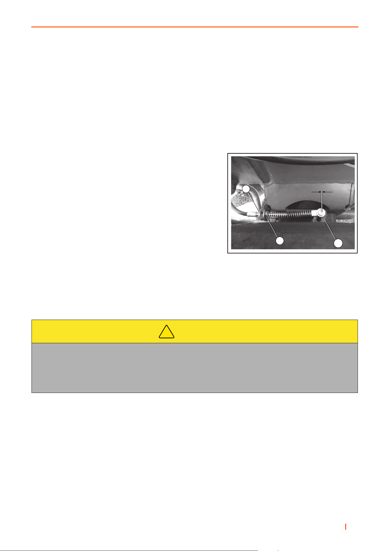
B
en 61
MAINTENANCE 7
7.13 HANDBRAKE _______________________________________________________
Place the front axle on axle stands and remove the front wheels. Inspect the discs and pads for wear and replace
if necessary. Remove all debris from around the brake assembly and ensure the calliper is free to float.
To Adjust
a. Release locknut's A.
b. Adjust cable until 1mm of movement is obtained at caliper lever B when the hand brake is NOT applied.
c. Adjust both brake calipers equally.
d. Tighten nuts A.
e. Check hand brake operation. The hand brake lever should
raise between eight and eleven clicks on the ratchet with a
force of 33kgf
7.14 TYRES _____________________________________________________________
Keep tyres properly inflated to prolong tire life. Check inflation pressure while the tyres are cool. Use an accurate,
low pressure tyre gauge.
Keep tires inflated to the air pressure specified. See Specifications 3.2
CAUTION
Caution must be used when inflating a low pressure tyre to the recommended pressure. Check pressure
with a low pressure tyre gauge before connecting an air hose to a partly inflated tyre.
Due to the low air volume requirements of a small tyre, over inflation may be reached in a matter of a few
seconds, which could cause the tyre to explode.
!
A
A
1mm
B

en 62
7 MAINTENANCE
7.15 MACHINE MAINTENANCE GENERAL ___________________________________
Other Regular Service
• Verify proper operation of safety interlock switches (Seat switch, etc.)
• Ensure nuts and bolts remain tight.
• visually inspect for hydraulic leaks.
• Keep engine bay clear of debris.
• Keep tyre pressure at correct level. See Section 3.2
• Follow the engine manufacturer’s maintenance recommendations.
• If a label becomes worn or removed, see the LABELS section of this manual or the tractor Parts Manual for
replacement information.
Storage
• Store petrol or diesel fuel in an approved container in a cool dry place.
• Keep the machine and fuel containers in a locked storage place to prevent tampering and to keep children
from playing with them.
• Do not store fuel or petrol / diesel fuel powered equipment in any closed area where heating appliances,
pilot lights or any sort of open flame is present.
• Before storing, allow the engine to cool, and drain fuel completely from fuel tanks and containers.
• When the vehicle is not being used for an extended period, the tyre pressures must be increased. Inflate to
the maximum rating on the tyre wall to make sure that flat spots do not occur. Decreased the tyre pressure
before the vehicle is put into operation.
• Maximum safety and best mowing results can only be expected if the mower is maintained and
operated properly.
7.16 LUBRICATION OF CUTTING UNIT ______________________________________
Cleaning
The cutting heads should be washed after use each days and dried as well as possible to prevent rust.
Lubrication
The lubrication fittings at each end of both the front and rear rollers, as well as the reel bearings at each end
should be lubricated periodically (approximately once each week). Use only enough lubricant to keep the
bearings from drying out. Too much lubricant may drop from mower onto turf, causing damage to the grass.
NOTICE
When washing machine with pressure spray washers or steam cleaners, avoid washing bearing areas
because cleaning solutions might penetrate bearing seals and cause premature bearing failure.

B
en 63
ADJUSTMENTS 8
8.1 TRACTION CONTROL PEDAL___________________________________________
ADJUSTING MOW SPEED
To determine mow speed, run a time check on how fast the
unit travels in a distance of 50’ (15.24 M). Prepare a level
surface with enough room to start and end beyond the 50’
marks.
Place a stake in the ground where you want to begin timing
the unit. Measure and place another stake at a distance of
50’ (15.24 M). Lower the cutting heads and press the direc-
tion pedal forward so the unit is traveling at full throttle (the
cutting heads should be in the neutral position when timing
the unit).
Begin timing the unit when the centre of the front tire aligns
with the first stake. Stop timing when the centre of the front
tire aligns with the stake placed at 50’ (15.24 M). Estimated
time for 3.8 mph (6.1 Km/hr) will be approximately 8.8 to 9.2
seconds. If there is a significant difference in the times listed
above, you can adjust the mow speed as follows.
To Adjust Transport Speed Stop.
a.Loosen locknuts (3).
b.Adjust bolt (2).
c.Tighten locknuts (3).
To Adjust Mow Speed Stop.
a.Loosen locknuts (5).
b.Adjust screw (4).
c.Tighten locknuts (5).
2
3
5
4
1
1. Direction/Speed Pedal
2. Transport Stop
3. Locknuts
4. Mow Stop
5. Locknuts
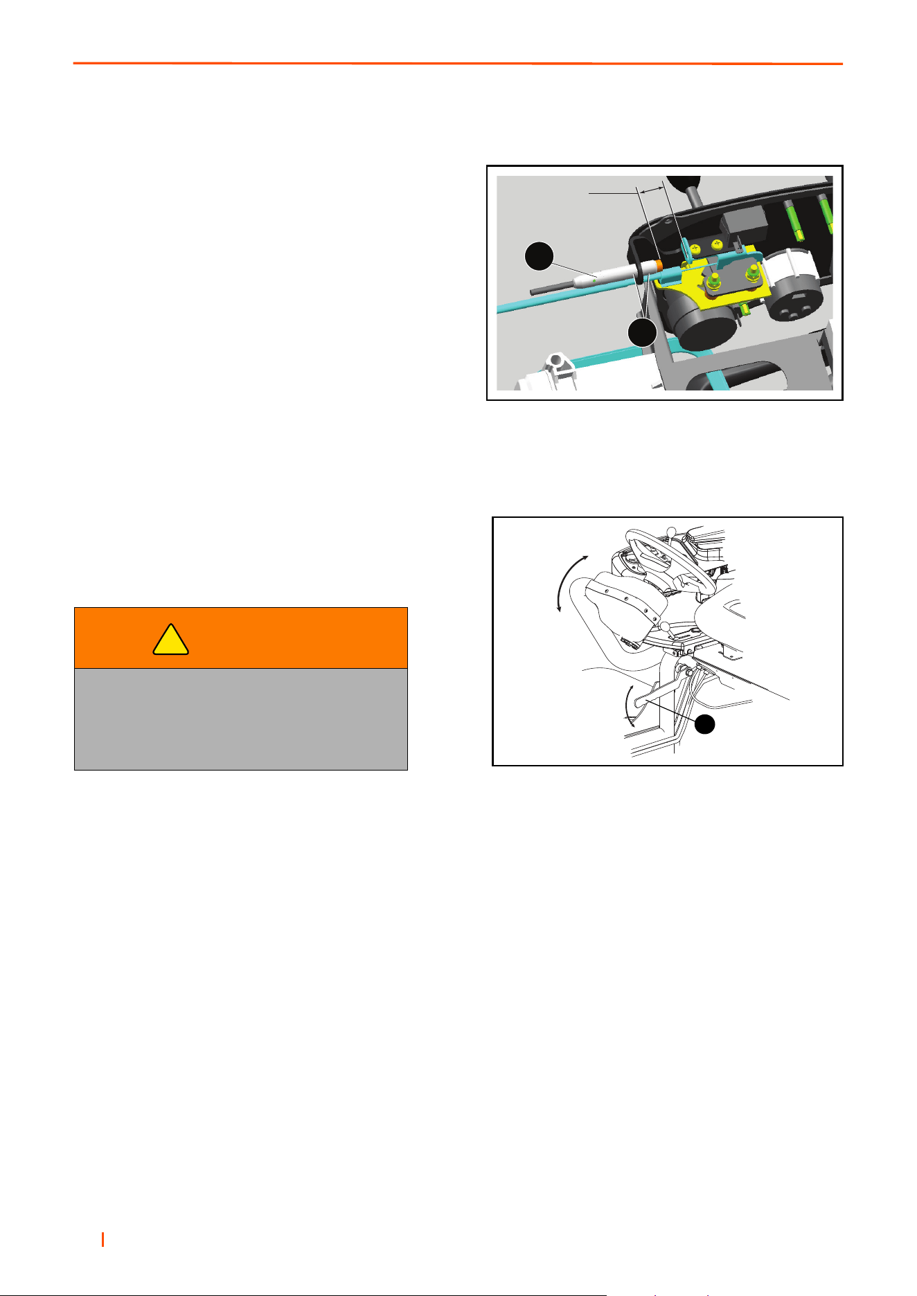
en 64
8 ADJUSTMENTS
8.2 ADJUSTING SPEED CONTROL SWITCH __________________________________
The speed control sensor is positioned under the control
panel. The mechanism is activated when the speed control
lever is cycled from the transport and mow positions.
To set the sensor (A), position the control lever in the “mow”
position, loosen nuts (B), and adjust sensor until a gap of
4mm is achieved. Tighten nuts. Cycle control lever to the
“transport” position, to ensure bolt head is clear of switch.
To ensure correct set-up, the cylinders MUST only rotate
when the switch is activated. i.e the Mow position.
8.3 STEERING ARM ADJUSTMENT _________________________________________
Support the control arm to avoid a sudden drop while adjusting its height. Loosen the Locking Lever (A) to allow
the steering wheel and control arm to be adjusted up or down. Tighten the locking lever when steering wheel is at
the desired position.
WARNING
DO NOT attempt to adjust the control arm
position while the machine is moving.
The operator may loose control, causing
possible injury to themselves or bystanders.
!
4mm
A
B
A

B
en 65
ADJUSTMENTS 8
8.4 REAR SWING OUT ARM _______________________________________________
1.The grass catcher MUST BE removed before you
swing the arm out.
2.Release the latch (1).
3.Pull the handle (2) and swing the rear arm and cutting head out.
4.After you are properly seated in the operator's seat, restart the unit and lower the cutting heads.
5.Shut off the unit and remove the rear cutting head for service.
6.After you have completed your servicing, secure the cutting head to the rear arm.
7.After you are properly seated in the operator's seat, restart the unit and raise the cutting heads.
8.Shut off the unit and swing the rear arm back under the unit and secure the arm with the draw latch.
9.Install the grass catcher.
NOTICE
The rear swing out arm is to allow you easy access
to the rear cutting head. The cutting heads must be
in the raised position.
DO NOT swing the arm out with the cutting heads in
the lowered position.
WARNING
To avoid the possibility of serious injury, ALWAYS be properly seated in the operator's seat while
the engine is running.
NEVER attempt to drive the machine while the rear arm is not secured by the draw latch. Driving
the machine with the rear arm out, will result in damage to the machine and/or cause serious
injury or death of the operator and/or bystanders.
!

en 66
8 ADJUSTMENTS
8.5 LEVELLING LINKAGE FOR THE FRONT CUTTING HEADS ___________________
1.With the unit on a level surface (recommend concrete
surface), place cardboard underneath all three of the
cutting heads.
2.An additional person is needed to stand 3 meters in front of the unit to check on how level the front heads are
when lowering. Lower the cutting heads and ensure the entire width of the front heads are parallel with the level
surface as the heads touch the cardboard.
3.If they do not touch evenly, make an adjustment using the adjusting connector. Repeat procedure as needed
until the two front heads touch evenly on the level surface.
NOTICE
The dimensions in the figure are factory preset and
the leveling linkage should not need
adjusting. After some time the linkage may
require some adjusting. If it is required, only
make adjustments on the adjusting connector (E).
WARNING
This procedure must be performed as specified and only by properly trained service personnel.
During this entire procedure the reel enable switch must be in the off position. Turning on the
reel enable switch will result in damage to the unit and/or serious personal injury or death to you
the operator or bystanders.
!

B
en 67
ADJUSTMENTS 8
8.6 SEAT ADJUSTMENT __________________________________________________
Milsco XB200
Pull out on the adjustment lever located under the left side of
the seat. Slide the seat to the desired position and release
the lever.
Grammer MSG 65
Safety
Driver's seats that have been adjusted incorrectly have a smaller moving area. In order to prevent any personal
injury, the seat must be adjusted for the driver's weight.
To prevent injury, no objects should be placed within the moving area of the driver's seat.
To eliminate any risk of accident, the settings must be checked to ensure they are correctly engaged before the
vehicle is driven.
Adjustments must not be made While driving.
Only touch the handle for setting the fore/aft adjustment at the indented grip provided for that purpose (do not put
your whole hand around it). Risk of crushing.
After removal of the backrest upholstery, the backrest frame must be supported, for example held in place, before
the backrest adjuster is operated. If you fail to do so, there is a danger that the backrest frame may jerk forward
and cause injury.
Any changes to the series standard of the seat (for example fitting parts which are not original Grammer AG parts)
may impair the safety standard to which it has been tested. Functions may be impaired, threatening your safety.
For this reason, any changes in design of the seat must be approved by Grammer AG.
Do not hold onto the covers for lifting the driver's seats. If you do so anyway, there is an increased risk injury due
to loosening or breaking covers.
Before you remove the driver’s seat, disconnect all plug-in connections between the seat and the vehicle supply
network. When you replace the plug-in connectors, make sure they are tight (dust, water).
Seatbelts are fitted or can be retrofitted to the driver’s seat. Seatbelts may only be fitted on approval of the vehicle
manufacture, as they increase the load in the seat mounting area. Seatbelts must be fitted in accordance with spe-
cific national regulations and guidelines, and must be approved by Grammer AG.
Seatbelts must be fastened before driving.
The seatbelts must be replaced after an accident.
Where seatbelts are fitted to the driver's seat, the seat and seatbelt mounting must be checked additionally by spe-
cialist personnel after an accident has occurred.
Fasteners must be checked regularly for tight seat. If the seat wobbles, there may be loose bolts or other faults.
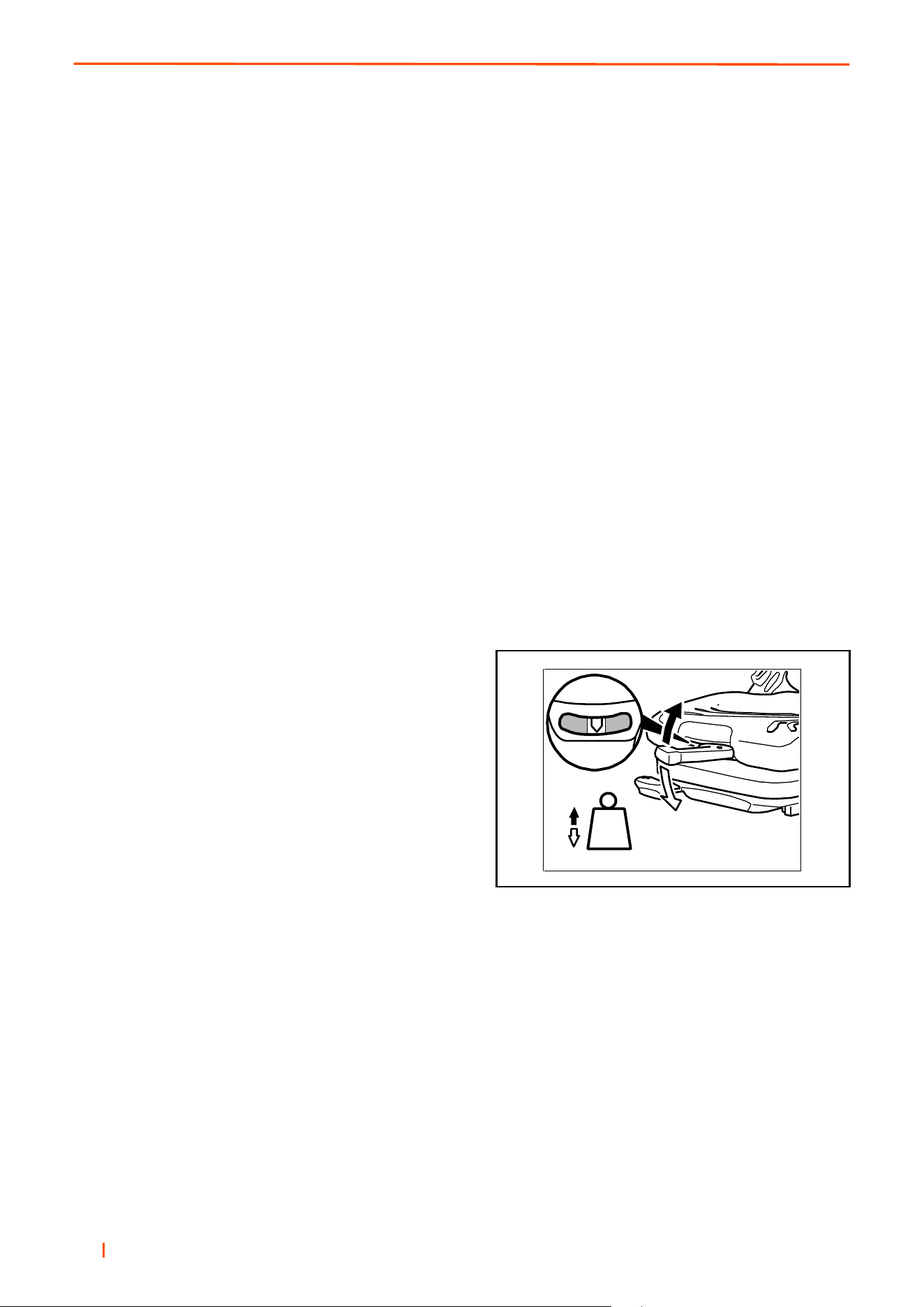
en 68
8 ADJUSTMENTS
f you notice that the seat does not function correctly (for example a defective suspension of the driver's seat; im-
proper curvature of the lumbar support or damaged bellows), contact a specialist workshop immediately to arrange
for repairs to be carried out. If you fail to do so, your health may be affected and the risk of an accident increased.
Before the vehicle is used, switches that might be in the seat (for shutting down mechanical equipment when the
driver leaves his/her seat) must be checked for proper function. If malfunctions are detected, the vehicle must not
be driven.
Loads must not be placed on seats with a built in switch, except for the driver’s weight during normal use, as the
vehicle may otherwise start to move by itself. If you take off the weight from the seat while driving, this will cause
the vehicle to stop.
Do not indent the bellows while there is load on the driver’s seat.
Make sure that the interior of the drivers seat remains free of foreign objects or liquids.
Seat functions and operation
Weight adjustment
The seat is adjusted for the driver’s weight with the driver sitting on the seat. Fold out the weight adjustment lever
completely, hold it at the front and move it upwards or downwards (10 movements from minimum to maximum).
Before every new movement, bring the lever back to the starting position (audible locking sound). The driver’s
weight has been set correctly, when the arrow is in the middle of the viewing window.
• To prevent damage to the health and material, the setting for the driver’s weight must be checked and adjusted
as necessary before the vehicle is driven.
• When the minimum/maximum has been reached, you can
notice an empty movement in the handle.
• When you have set the weight, fold the lever completely
into the locking.
762
min.
max.
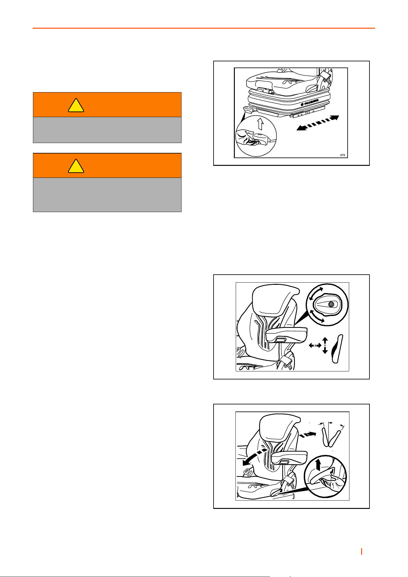
B
en 69
ADJUSTMENTS 8
Fore/aft adjustment
The fore/aft adjustment is released by lifting the locking
lever.
• After the adjustment, the locking lever must latch into the desired position with an audible click. It should not
be possible to move the driver’s seat into another position when it is locked.
• Do not lift the locking lever with your leg or calf.
Lumbar support
The lumbar support increases both the seating comfort
and the performance of the driver. By turning the
adjustment knob upwards, the curvature in the upper part
of the backrest cushion can be adjusted. By turning the
knob downwards, the curvature in the lower part of the
backrest cushion can be adjusted.
0 = No curvature
1 = Max. curvature at the top
2 = Max. curvature at the bottom.
Backrest adjustment
Pull up the locking lever to release the backrest catch.
When releasing the backrest catch, do not apply load to
the backrest by pressing against it. By exerting pressure
on or off the front or rear part of the seat pan it can be
moved to the desired position. Release the locking lever to
lock the backrest.
• It should not be possible to move the backrest into
another position after it has been locked.
WARNING
Risk of accident.
Do not operate the locking lever while driving.
WARNING
Risk of crushing.
only touch the lever at the indented grip,
do not reach back under the lever.
!
!
765
1
0
2
2
1
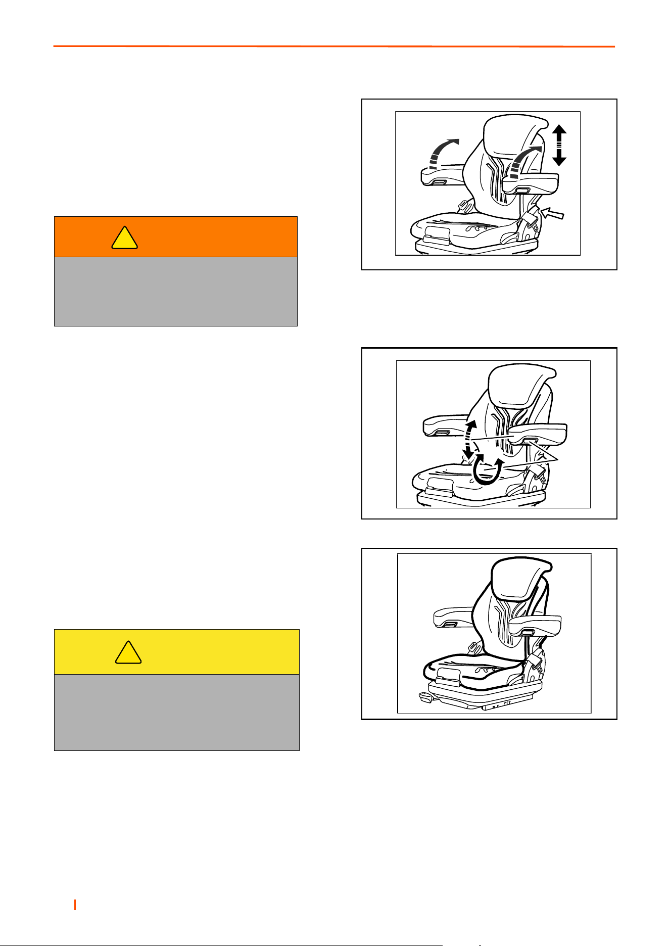
en 70
8 ADJUSTMENTS
Armrests
The armrests can be folded back if required and the height in-
dividually adjusted. To adjust the armrests for height, sepa-
rate the round cap (see arrow) from the cover, loosen the
hexagon nut (size 13 mm) behind it and adjust the armrests
to the desired position (5-steps) and tighten the nut again
(25Nm). Replace the cap onto the nut.
Armrest adjustment
The inclination of the armrests can be modified by turning the
adjustment knob. When turning the knob to the outside (+) the
front part of the armrest will be lifted, when turning the knob
to inside (-) it will be lowered.
Maintenance
Dirt can impair the function of the seat, So make sure you
keep your seat clean. Upholstery does not need to be re-
moved from the seat frame for cleaning.
ATTENTION: Do not clean the seat with a pressure washer.
When cleaning the upholstery, make sure the upholstery is not soaked.
Use standard commercially available upholstery or plastics cleaning agent. Test first for compatibility on a small,
concealed area.
WARNING
If the belt roller is fitted, do not install the
armrest in the lowest position as otherwise
the belt roller might not function correctly.
Carry out a functional test of the belt roller.
CAUTION
Take care with the backrest - it may jerk forward
and cause injury.
When cleaning the backrest cushion, the back-
rest must be held in place when operating
the backrest lever.
!
!
770
767
+
-
768

B
en 71
ADJUSTMENTS 8
DANGER
When the machine is being used off road,
whether cutting grass or not, the seat belt
should only be worn when a ROPS frame is in
place and deployed.
This rationale is based on the fact that a seat
belt must be worn with a ROPS to comply with
the Machinery Directive 98/37/EC Sections
3.2.2, Seating & 3.4.3, Rollover.
Ransomes Jacobsen Limited
recommends that a local risk
assessment is completed by the
owner / user of the machine to
determine any exceptions to this seat
belt wearing rule e.g. use of the
machine next to water or on
the highway.
!
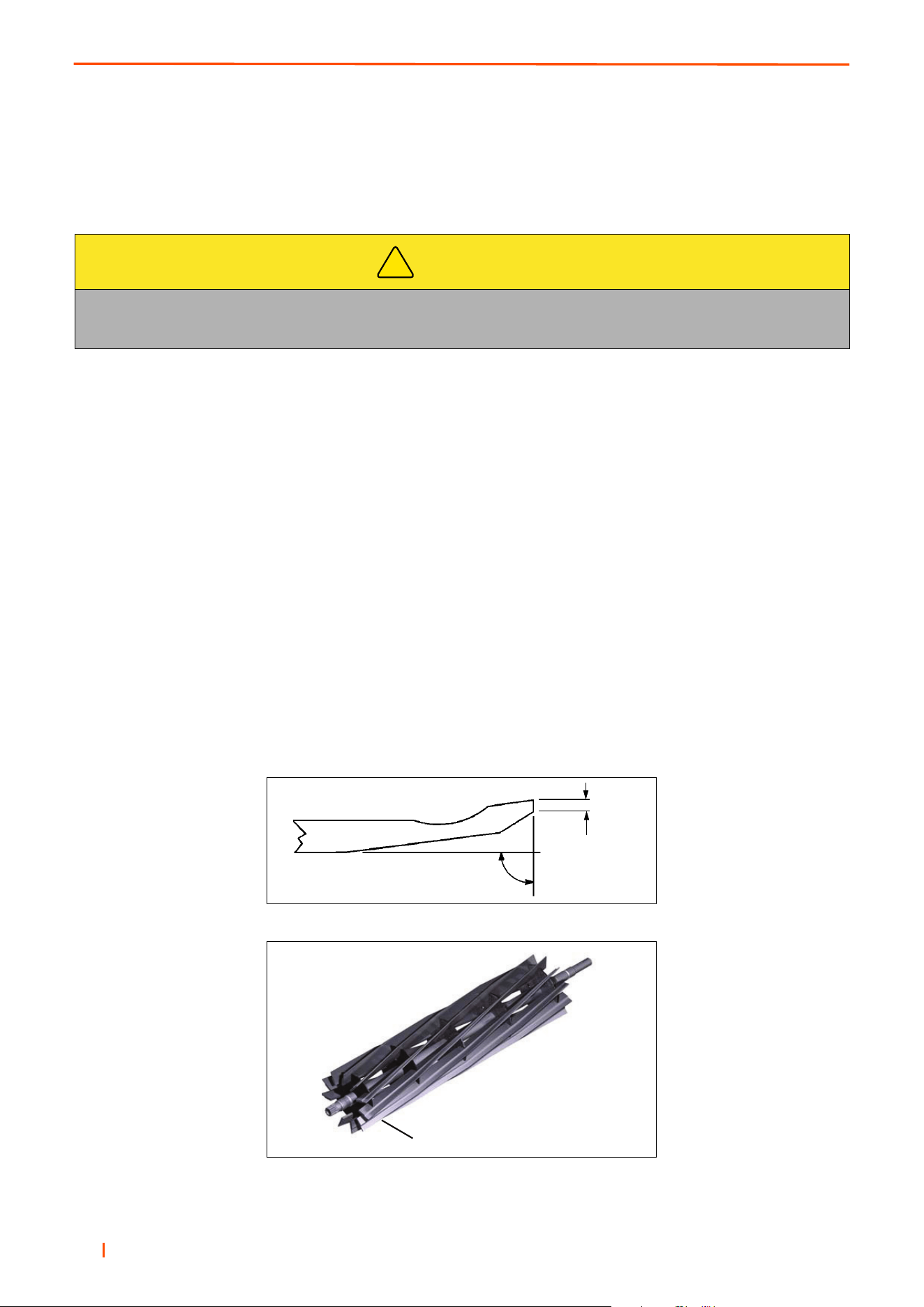
en 72
8 ADJUSTMENTS
8.7 BEDKNIFE-TO-REEL TRUESET™ REEL __________________________________
(Pre-adjustment Check)
1. Check the reel bearings for end play or radial play. There should be no end play or radial play. See 8.10.
2. Inspect the reel blades and bedknife to insure good sharp edges without bends or nicks.
a. The leading edge of the reel blades must be sharp, free of burrs and show no signs of rounding off.
b. The bedknife and bedknife backing must be securely tightened. The bedknife must be straight and sharp.
c. A flat surface of at least 1/32 in. (0.8 mm) minimum must be maintained on the front face of the bedknife.
Use a standard flat file to dress the bedknife.
3. If wear or damage is beyond the point where the reel or bedknife can be corrected by the lapping process,
they must be reground.
4. Proper reel-to-bedknife adjustment is critical. A gap of 0.001 to 0.003” (0.025 to 0.076 mm) must
be maintained across the entire length of the reel and bedknife.
5. The reel must be parallel to the bedknife. An improperly adjusted reel will lose its sharp edges prematurely
and may result in serious damage to the reel and bedknife.
6. Grass conditions will also affect the adjustment.
a. Dry, sparse conditions will require a wider gap to prevent heat buildup and damage to the reel and
bedknife.
b. High quality grass with a good moisture content requires a closer gap (near zero).
CAUTION
To prevent personal injury and damage to the cutting edges, wear gloves and handle the reel
and bedknife with extreme care.
!
°
°
1/32”
(0.8 mm)
Leading Edge
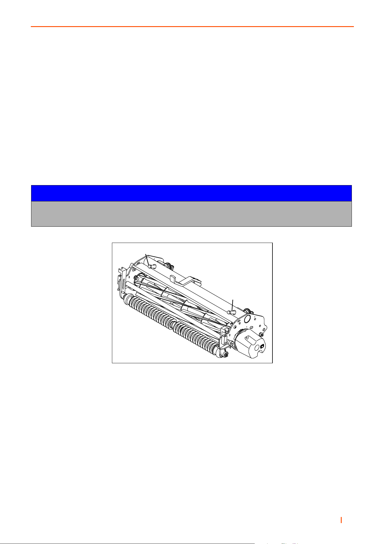
B
en 73
ADJUSTMENTS 8
8.8 BEDKNIFE ADJUSTMENT TRUESET™ REEL ______________________________
1. Read Section 8.7 before making the adjustment.
2. Start adjustment at the leading end of the reel, followed by the trailing end. The leading end of the reel
blades is that end which passes over the bedknife first during normal reel rotation.
3. Use adjusters (B and C) in Figure 9A, to adjust gap. Rotate adjusters (Clockwise) to close gap. Each click
of the adjuster moves the bedknife 0.001” (0.025 mm) closer to the reel.
a. Slide a feeler gauge or shim stock 0.001” - 0.003” (0.025 - 0.075 mm) between the reel blade and the
bedknife. Do not turn the reel.
b. Adjust the trailing end of the reel to the same gap in a similar manner then recheck the adjustment
at the leading end.
c. When the reel is properly adjusted to the bedknife, the reel will spin freely and you should be able to cut a
piece of newspaper, along the full length of the reel, when the paper is held at 90° to the bedknife.
NOTICE
Avoid excessive tightening or serious damage may result to bedknife and reel blades.
Reels must turn freely.
B
C
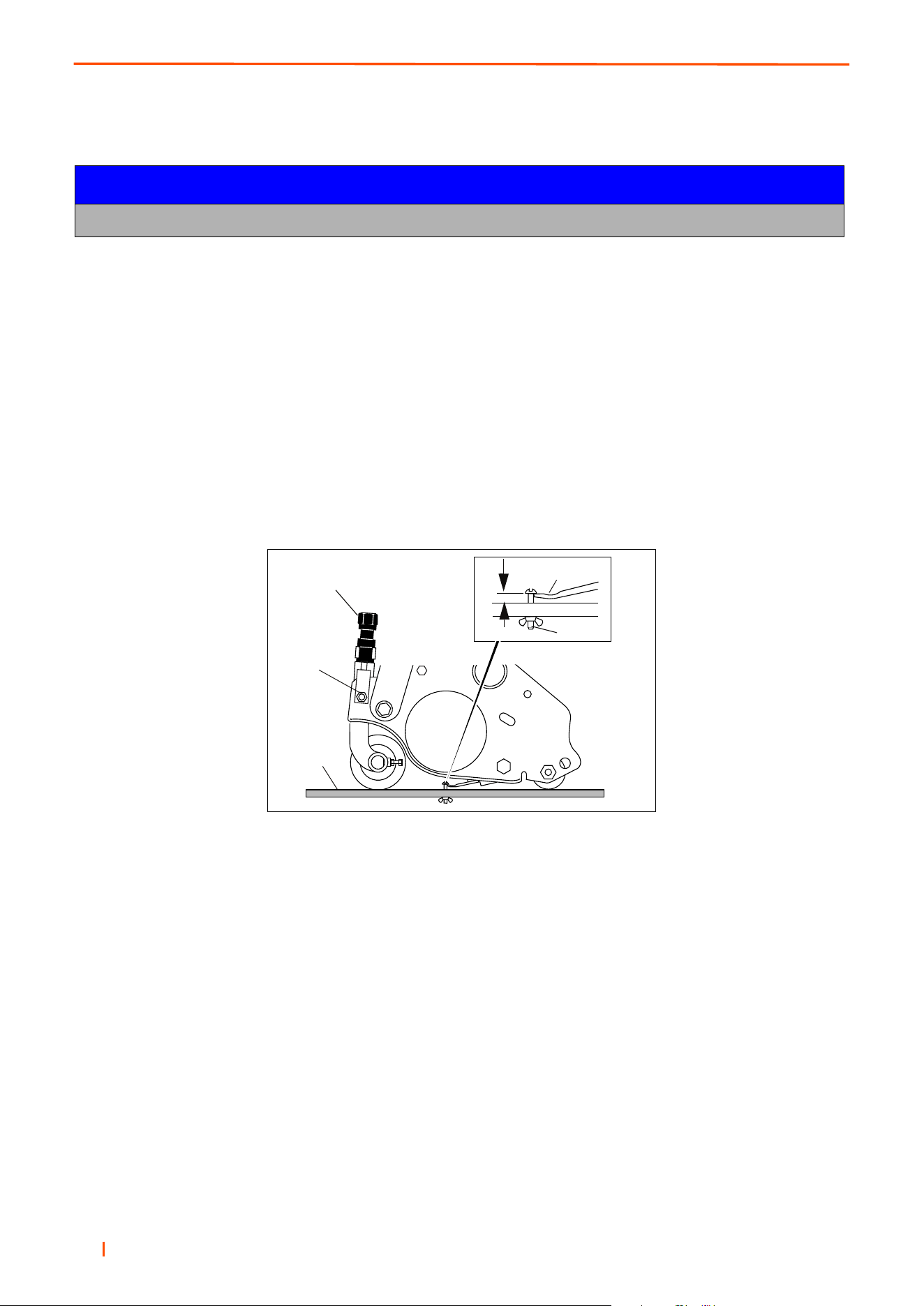
en 74
8 ADJUSTMENTS
8.9 CUTTING HEIGHT TRUESET™ REEL_____________________________________
1. Set desired cutting height on the gauge (E).
a. Measure distance between the underside of screw head and gauge block surface (F).
b. Adjust screw (H) to obtain desired height then tighten the wing nut.
2. Loosen the nuts on the front roller brackets (G) just enough to allow the adjuster knob (K) to raise or lower the
front roller.
3. Place gauge (E) across bottom of front and rear rollers near one end of roller.
4. Slide the head of gauge screw (H) over the bedknife (L) and adjust the knob (K) to close the gap between the
screw head and bedknife. Then tighten locknut (G).
5. Repeat Steps 4 and 5 on opposite end. Complete adjustment to one end before adjusting opposite end.
6. Tighten nuts (G) and recheck each end.
NOTICE
Always make the reel to bedknife adjustment before adjusting height of cut. (Sections 8.7 and 8.8).
F
K
G
E
H
J
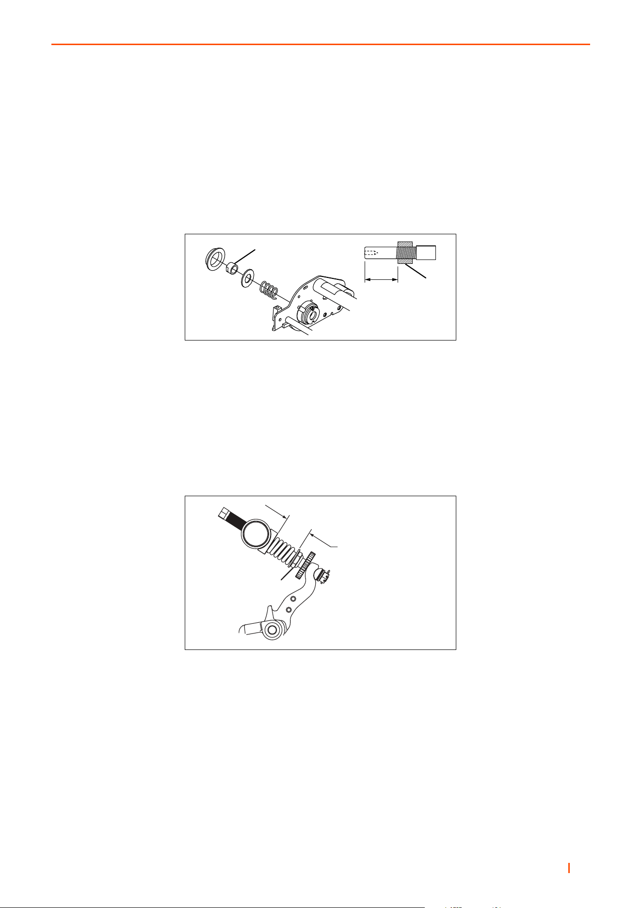
B
en 75
ADJUSTMENTS 8
8.10 REEL BEARING TRUESET™ REEL _____________________________________
Any radial play or excessive end play indicates bad bearings, a weak tension spring or a backed off nut.
1. Check bearing housing mounting hardware. Tighten or replace components as required. Carefully clean
threads with degreaser.
2. Apply a medium strength grade of Loctite to nut (P), then thread nut onto the reel shaft until the nut is 1-27/
32” (46 mm) from the end of the reel shaft.
3. Fill reel bearing housings with NLGI - Grade O grease after adjusting spring.
8.10.1 BEDKNIFE ADJUSTER SPRING TRUESET™ REEL_______________________
For proper operation, bedknife adjuster spring should be compressed to a dimension of 1-7/16 - 1-1/2 in.
(36.5-38 mm).
To adjust spring compression, loosen or tighten nut (R) to obtain a distance of 1-7/16 - 1-1/2 in. (36.5-38 mm).
After adjusting spring, check reel to bedknife adjustment.
P
P
1-27/32”
(46 mm)
R
1-7/16 to 1-1/2 in.
(36,5 - 38 mm)
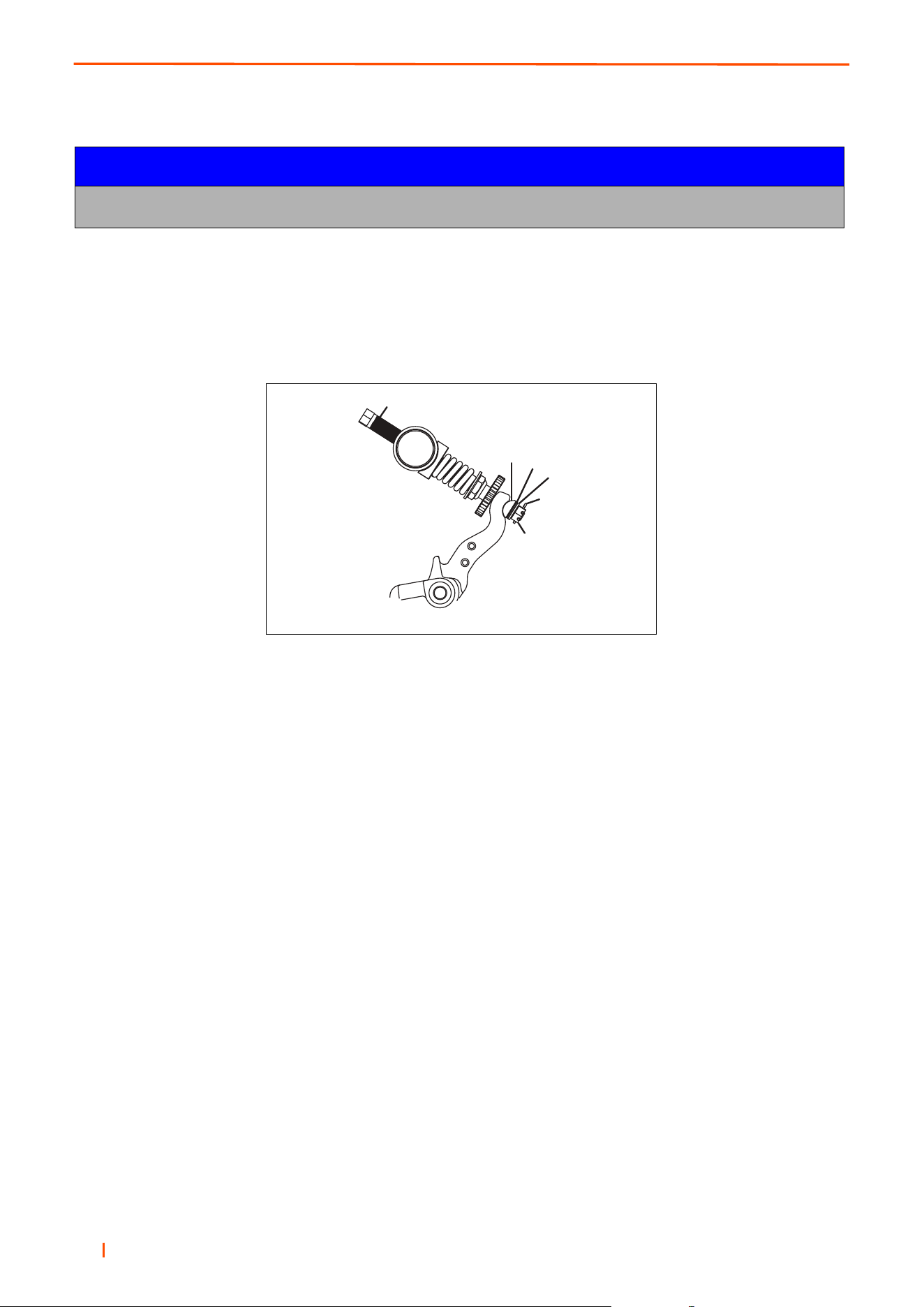
en 76
8 ADJUSTMENTS
8.11 KNIFE ADJUSTER TENSION TRUESET™ REEL _________________________
Remove cotter pin (U) and fully loosen, then tighten slotted nut (S) to remove clearance (no end play) between
components. Continue to tighten nut until next slot in nut aligns with hole in bedknife adjuster rod (T). Install new
cotter pin.
Check torque required to rotate adjuster rod (T). Maximum torque should be 24 in. lb. (2 ft. lb.) (2.7 Nm).
After adjusting nut, check reel to bedknife adjustment.
8.12 GRINDING BEDKNIFE TRUESET™ REEL ________________________________
Bedknife can be lowered out of the reel for grinding without completely removing the bedknife assembly.
1. Remove cotter pin (U), slotted nut (S), bellville washer (V), shim washer (W) if required), and half trunnion
(X). See Figure 9A.
2. Press down on adjuster end of rod (T) to rotate other end of the adjuster out of the bedknife finger.
3. Rotate bedknife backing to access the reel and bedknife for grinding.
4. After grinding, assemble bedknife using reverse order of removal. Check adjustment of bedknife adjuster
tension and reel to bedknife adjustment.
NOTICE
Over tightening slotted nut (S) will make bedknife adjuster rod (T) difficult to adjust.
U
V
W
X
S
T

B
en 77
ADJUSTMENTS 8
8.13 BEDKNIFE ADJUSTMENT CLASSIC XP™ REELS _________________________
Any adjustment to the clearance between the reel blades and the bedknife should be done at the leading end of
the reel first (the end at which each individual blade first crosses the bedknife). Then at the opposite end of the reel.
1. Loosen the lower adjustment screws at each end by turning them approximately 1/4 turn
counterclock- wise.
2. While rotating the reel backwards, turn the upper adjustment screws (leading end first) until there is
approximately.001, (.025mm) clearance. After adjusting both ends, recheck the leading end.
.
3. Using a wrench rotate the reel forward. The reel must turn freely and you should just be able to hear the
reel blades making slight contact with the bedknife.
4. After the bedknife is properly adjusted, tighten the lower adjustment screw at each end.
5. Test the cutting head by holding two strips of newsprint perpendicular to the bedknife. Rotate the reel with
a wrench. The reel must turn freely and each blade on the reel should cut one of the two strips of paper.
NOTICE
Too much clearance between the bedknife and the blades will result in poor cutting quality.
Too little clearance will cause excessive wear to the cutting edges and may cause damage to the
bedknife, reel blades or other components.
WARNING
To avoid the possibility of serious injury, NEVER attempt any cutting head adjustments while
the engine is running.
WARNING
NEVER rotate the cutting reel by pushing it with your hands or fingers.
Fingers can become caught between the reel and the frame resulting in serious injury.
Use a ratchet with a 9/16” socket on the end of the reel shaft to rotate it during adjustments and testing.
!
!
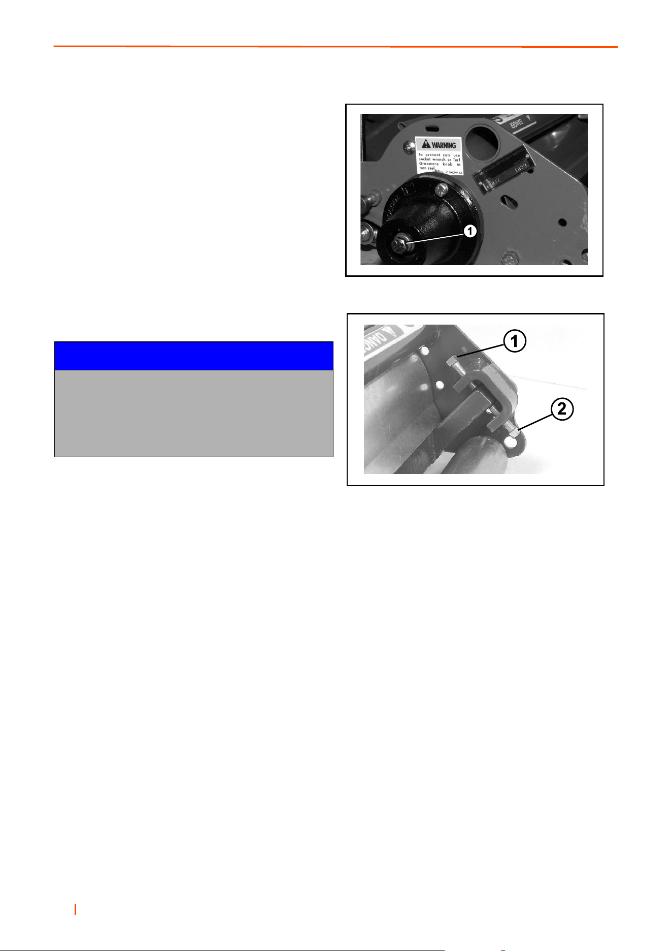
en 78
8 ADJUSTMENTS
8.14 HEIGHT OF CUT CLASSIC XP™ REELS _________________________________
Any adjustment to the clearance between the reel blades
and the bedknife should be done at the leading end of the
reel first (the end at which each individual blade first
crosses the bedknife). Then at the opposite end of the
reel.
1. Loosen the lower adjustment screws at each end
by turning them approximately 1/4 turn
counterclock- wise.
2. While rotating the reel backwards, turn the upper
adjustment screws (leading end first) until there is
approximately .001, (.025mm) clearance. After
adjusting both ends, recheck the leading end.
.
3. Using a wrench rotate the reel forward. The reel
must turn freely and you should just be able to hear
the reel blades making slight contact with the
bedknife.
4. After the bedknife is properly adjusted, tighten the lower adjustment screw at each end.
5. Test the cutting head by holding two strips of newsprint perpendicular to the bedknife. Rotate the reel with
a wrench. The reel must turn freely and each blade on the reel should cut one of the two strips of paper.
NOTICE
Too much clearance between the bedknife and the
blades will result in poor cutting quality.
Too little clearance will cause excessive wear to the
cutting edges and may cause damage to the
bedknife, reel blades or other components.
1. Rotate Cutting Reel with this Screw Head
1. Upper Adjustment Screw
2. Lower Adjustment Screw
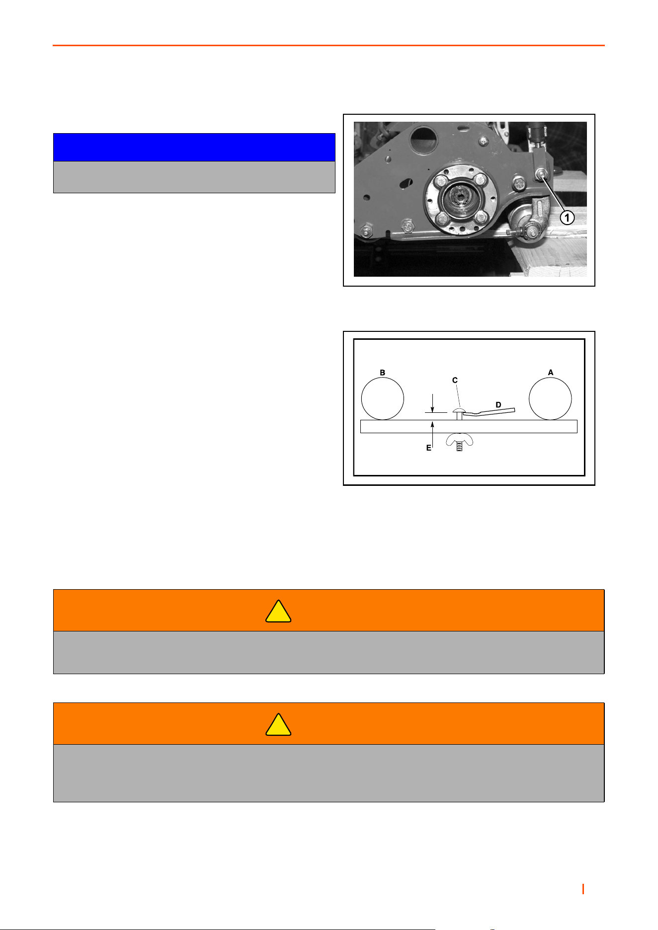
B
en 79
ADJUSTMENTS 8
8.15 HEIGHT OF CUT CLASSIC XP™ REELS _________________________________
Work Bench Setting.
1. Set the height of cut on the gauge block (Part No.
892010) by turning the wing nut until the distance
between the bottom of the screw head and the top
of the gauge block equals the desired height of cut.
2. Loosen the locking nut on one of the front roller
adjusting brackets just enough to allow adjustment.
3. Hold the gauge block (Part No. 892010) across the
bottom of both the front and rear rollers near the
roller adjustment bracket and adjust the front roller
until the cutting edge of the bedknife comes up to
touch the bottom of the gauge screw head.
4. Tighten the locking nut and repeat the procedure at
the other end. After adjustment has been made at
both ends, go back and recheck both ends.
5. Make sure all three cutting heads are set without
changing the height of the gauge screw.
NOTICE
All three cutting heads MUST be accurately set at the
same height of cut to ensure an even cut.
WARNING
To avoid the possibility of serious injury, NEVER attempt any cutting head adjustments while
the engine is running.
WARNING
NEVER rotate the cutting reel by pushing it with your hands or fingers.
Fingers can become caught between the reel and the frame resulting in serious injury.
Use a ratchet with a 9/16” socket on the end of the reel shaft to rotate it during adjustments and testing.
!
!
1. Loosen Locking Nut
Height of Cut Adjustment
A = Rear Roll
B = Front Roll
C = Gauge Screw Head
D = Bedknife
E = Height of Cut
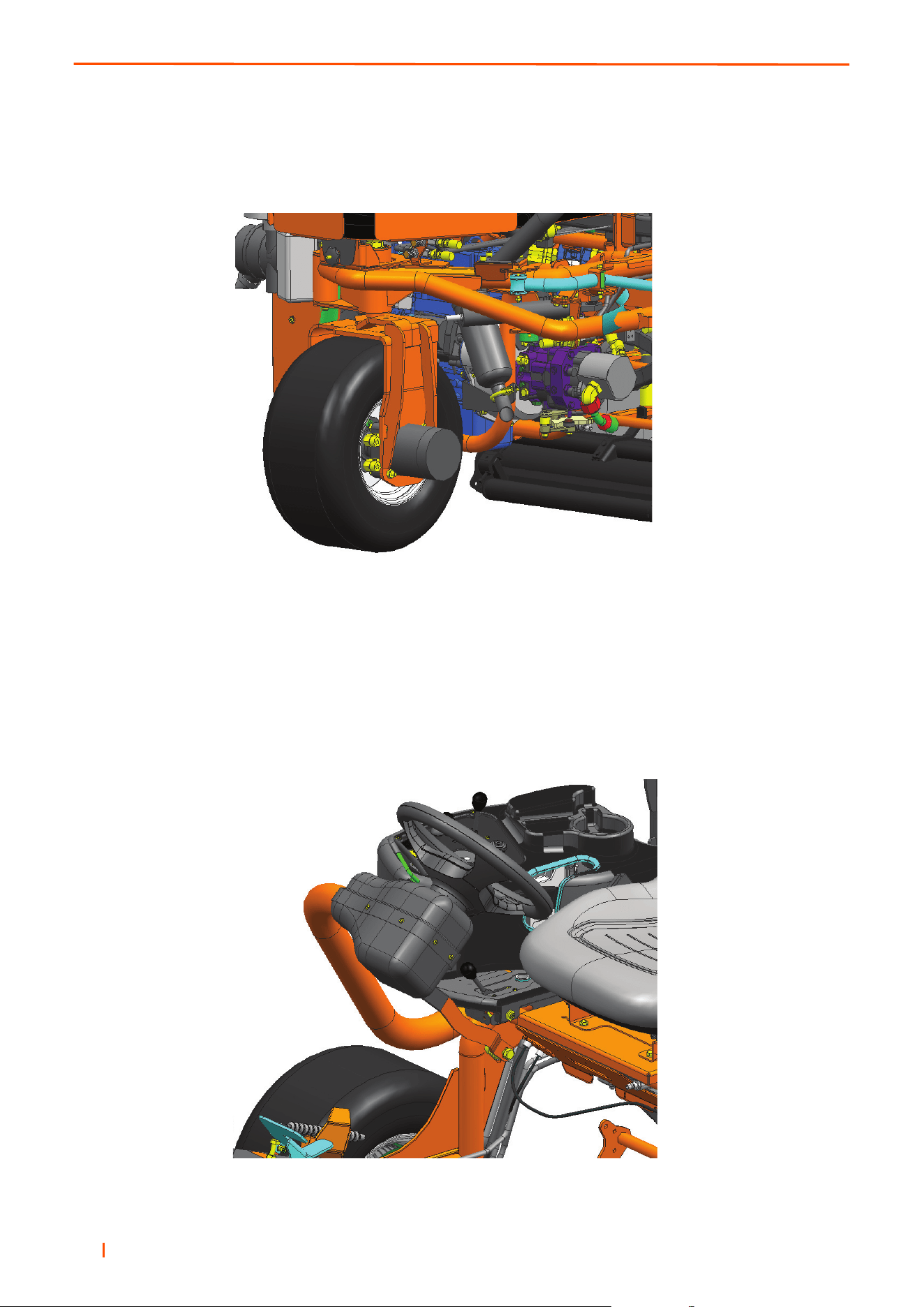
en 80
9 ACCESSORIES
9.1 THREE WHEEL DRIVE KIT _____________________________________________
Kit number: LMAC418
9.2 PADDLE KIT _________________________________________________________
kit number: LMAC412
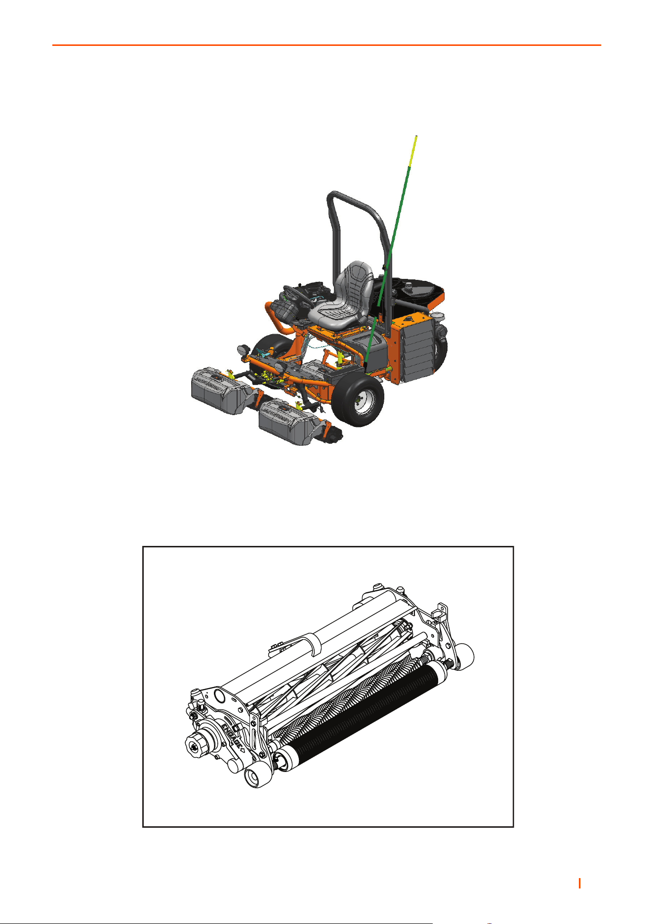
en 81
ACCESSORIES 9
9.3 DEW WHIP KIT _______________________________________________________
Kit number: LMAC415
9.4 GROOMER KIT _______________________________________________________
Kit number: 067912 (6.3mm spacing) 1/4 Inch
Kit number: 06 7914 (12.7mm spacing) 1/2 Inch

en 82
10 PROBLEM SOLVING
10.1 PROBLEM SOLVING GENERAL ________________________________________
Symptoms Possible Causes Action
Engine will not
start
Glow plug has not timed out Reset ignition switch and allow glow plug to time out before
cranking engine.
Battery low on charge or
defective.
Inspect condition of battery and battery connections.
Fuel tank empty or fuel
contaminated.
Fill tank with fresh fuel. Change filter. Bleed air from lines.
Blown fuse. Replace Fuse.
Defective starter relay. Test and replace relay if necessary.
Brake switch is not on. Ensure brake switch is on.
Mow switch set to cut. Set mow switch to off.
Transport pedal not in neutral. Remove foot from pedal, cheek pedal returns to the neutral
position.
Engine hard to
start or runs
poorly.
Fuel tank empty or fuel
contaminated.
Fill tank with fresh fuel. Change filter. Bleed air from lines.
Air Cleaner blocked or dirty. Check air cleaner, replace as necessary.
Injectors, fuel pump. Consult engine manual.
Other Engine Problem. Consult engine troubleshooting guide.
Engine Stops
Fuel tank empty. Fill with fresh fuel and bleed lines.
Interlocks not set before
leaving operators seat.
Ensure Parking Brake is on & Mow switch is in the off
position.
Engine
Overheating
Coolant level low. Inspect and add 50/50 antifreeze solution if required
Radiator air intake restricted. Clean wire mesh guard at radiator.
Waterpump/alternator belt or
fan belt loose or broken.
Inspect waterpump/alternator belt and fan belt. Tighten if
necessary.
Battery not holding
charge. Battery
light on
Loose or corroded battery
terminals.
Inspect terminals, clean and tighten as required.
Low electrolyte level in battery. Refill battery with distilled water.
Alternator belt loose or broken. Inspect waterpump/alternator belt. Tighten if necessary.
Alternator defective. See engine manual.
Decks cut
unevenly Poor
quality of cut.
Cutting blades are worn. Replace blades.
Engine speed too low. Check engine speed, run engine at full throttle.
Cutter motors worn. Check case drain leakage & flow check cutting circuit.
Ground speed to high. Set work speed stop.

en 83
PROBLEM SOLVING 10
NOTES

en 84
11 QUALITY OF CUT
11.1 QUALITY OF CUT PROBLEM SOLVING __________________________________
If required perform a “test-cut” to assess the performance of the mower before you begin the repairs.
When the work is completed, repeat the “test-cut” to check the mower performance.
The following items must be checked and set correctly to make sure of an effective assessment.
1. Blade Sharpness
2. Blade Speed
3. Mowing (Ground) Speed
4. Height-of-Cut (HOC)
5. Rake Angle
6. Caster/Roller and Roller Bearing Condition
7. Tyre pressures
8. General wear and tear of the machine
11.2 STEP CUTTING______________________________________________________
NOTE: Arrow indicates direction of travel.
“Step cutting” occurs when the grass is cut higher on
one side. The cause is mechanical wear or incorrect
setting of the roller or deck caster.
Possible Cause Correction
The HOC (height-of-cut) settings are different on the
side of one cutting implement.
Check HOC adjustment of cutting implement
Worn roller bearings or deck caster wheels. Check and replace the roller bearings, deck
caster wheels.
Changes in turf density Change the direction of cut.
The machine ride height is uneven side to side. Check and adjust the tyre pressure.
(See section 3.2)
General wear and tear of the machine. Check machine for any damaged or worn parts.
TN0221

en 85
QUALITY OF CUT 11
11.3 SCALPING__________________________________________________________
NOTE: Arrow indicates direction of travel.
“Scalping” is a condition in which some areas are cut
shorter than the set height of cut. This results in very
short grass or brown areas. The cause is a low height-
of-cut (HOC) setting, rough surface.
Possible Cause Correction
The HOC (height-of-cut) settings are low for the
conditions.
Check and adjust the HOC settings.
(See section 8.14)
The mower cannot follow the ground in this direction.
Change the direction of cut.
The height of grass is being reduced too much in one
pass.
Mow more often or raise the height of cut.
Damaged anti-scalp skid/roller Replace or repair
Rotary Deck caster stance too wide Move deck caster towards the centre of the deck
TN0222
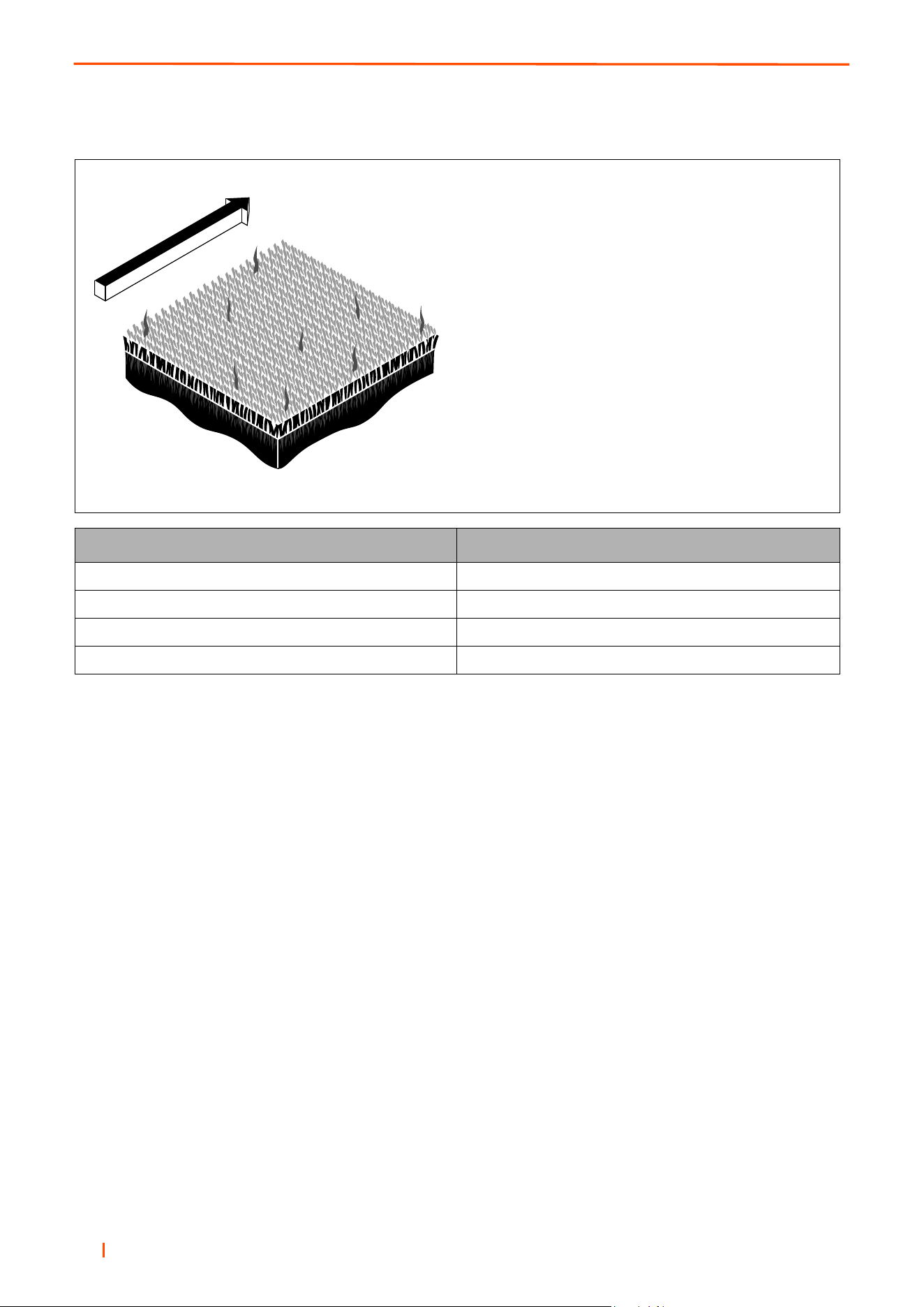
en 86
11 QUALITY OF CUT
11.4 STRAGGLERS ______________________________________________________
NOTE: Arrow indicates direction of travel.
“Stragglers” are separated blades of incorrectly
cut grass.
Possible Cause Correction
The cutting blades are blunt. Replace or sharpen blades.
Cutting Speed to fast for grass conditions. Decrease the cutting speed.
Too much grass is being removed in one pass. Mow more often or raise the height of cut.
Grass lain flat in direction of cut. Change the direction of cut on each cut.
TN0223

en 87
QUALITY OF CUT 11
11.5 STREAKS __________________________________________________________
NOTE: Arrow indicates direction of travel.
A streak is a strip of longer grass in the cutting area.
The cause is a damaged blade.
Possible Cause Correction
Damaged or worn blades. Replace the blades.
Blades fitted incorrectly. Install blades correctly.
Low lift blades do not lift the grass sufficiently to
be cut.
Try high lift blades.
Front castor wheels flattened grass before it is cut. On rotary deck, move the castor wheels to the outer
edges of the deck and remove anti scalp rollers.
Wet grass is flattened before the cut. Mow when ground conditions have improved.
TN0224

en 88
11 QUALITY OF CUT
11.6 WINDROWING ______________________________________________________
NOTE: Arrow indicates direction of travel.
“Windrowing” is an increase of cut grass arranged in
rows in the discharge area of the rotary cutting imple-
ment, this appears as cut grass in the direction
of travel.
Possible Cause Remedy
The Height of grass is being reduced by too much in
one pass.
Mow more often or raise the height of cut.
Try high lift blades.
Incorrect blade choice. Use original Ransomes blades: Low Lift, High Lift or
Eliminator blades.
Damaged baffles. Check for damage, repair/replace.
Mowing while grass is very wet. Mow when grass conditions improve.
TN0225

en 89
QUALITY OF CUT 11
11.7 CLUMPING _________________________________________________________
“Clumping.” This problem is identified by the appear-
ance of clumps of grass in the discharge area.
Possible Cause Correction
Front edge of deck bulldozing grass between front
castor wheels and anti-scalp rollers.
Move the castor wheels to the outer edges of the deck
and remove anti scalp rollers.
Extreme volume of grass is not discharged quickly
enough from the deck.
Consider using a cut and clear kit
(152cm rotary deck only).
Damaged baffles. Check for damage, repair/replace.
Mowing while grass is very wet. Mow when grass conditions improve.
Grass discharge build up on machine dropping off. Remove grass from machine regularly.
TN1281

en 90
11 QUALITY OF CUT
11.8 INSUFFICIENT MULCHING ____________________________________________
“Insufficient Mulching.” This problem is identified by
long lengths of cut grass not sufficiently chopped.
Possible Cause Correction
Incorrect blades fitted.
Ensure standard low lift blades are fitted
Try Shredder blades.
Cut and clear kit fitted.
Fit standard baffles and blades.
Long lengths of grass are not sufficiently chopped. Consider dropping the rear height of cut pins 1 hole
to flatten the deck.
Cutting at more than the recommended speed. Decrease the cutting speed.
Too much grass is being removed in one pass. Mow more often or raise the height of cut.
Level of mulching insufficient. Install mulching kit.
Mulched
Non Mulched
TN1280

en 91
QUALITY OF CUT 11
11.9 TORN CROWNS _____________________________________________________
“Torn Crowns” This problem is identified when clumps
of grass (Crowns) are torn up rather than cut.
Possible Cause Correction
Too much material.
Cut more frequently, increase HOC.
Worn blade edge.
Sharpen or Replace damaged blades.
Cutting too fast for conditions. Decrease the cutting speed.
TN1234

en 92
11 QUALITY OF CUT
11.10 LAYING UNCUT GRASS______________________________________________
NOTE: Arrow indicates direction of travel.
“Laying uncut grass.” This problem is identified by
areas of grass that have been left uncut and laid flat.
Possible Cause Correction
Mowing (ground) speed is too fast.
Cut more frequently, increase HOC.
HOC set close to the actual grass height.
Reduce HOC.
Too much material to clear rear of unit, brought round
the unit pushing over the grass.
Reduce mowing (ground) speed.
Excessive cut grass wrapped on the front of the
cutting blades resulting in blunt blades beating the
grass down.
Cut when grass conditions improve. Remove
excessive grass build up. Sharpen or replace
damaged blades.
Grass always cut in same direction. Cut grass in opposite direction.
TN1234

en 93
QUALITY OF CUT 11
NOTES
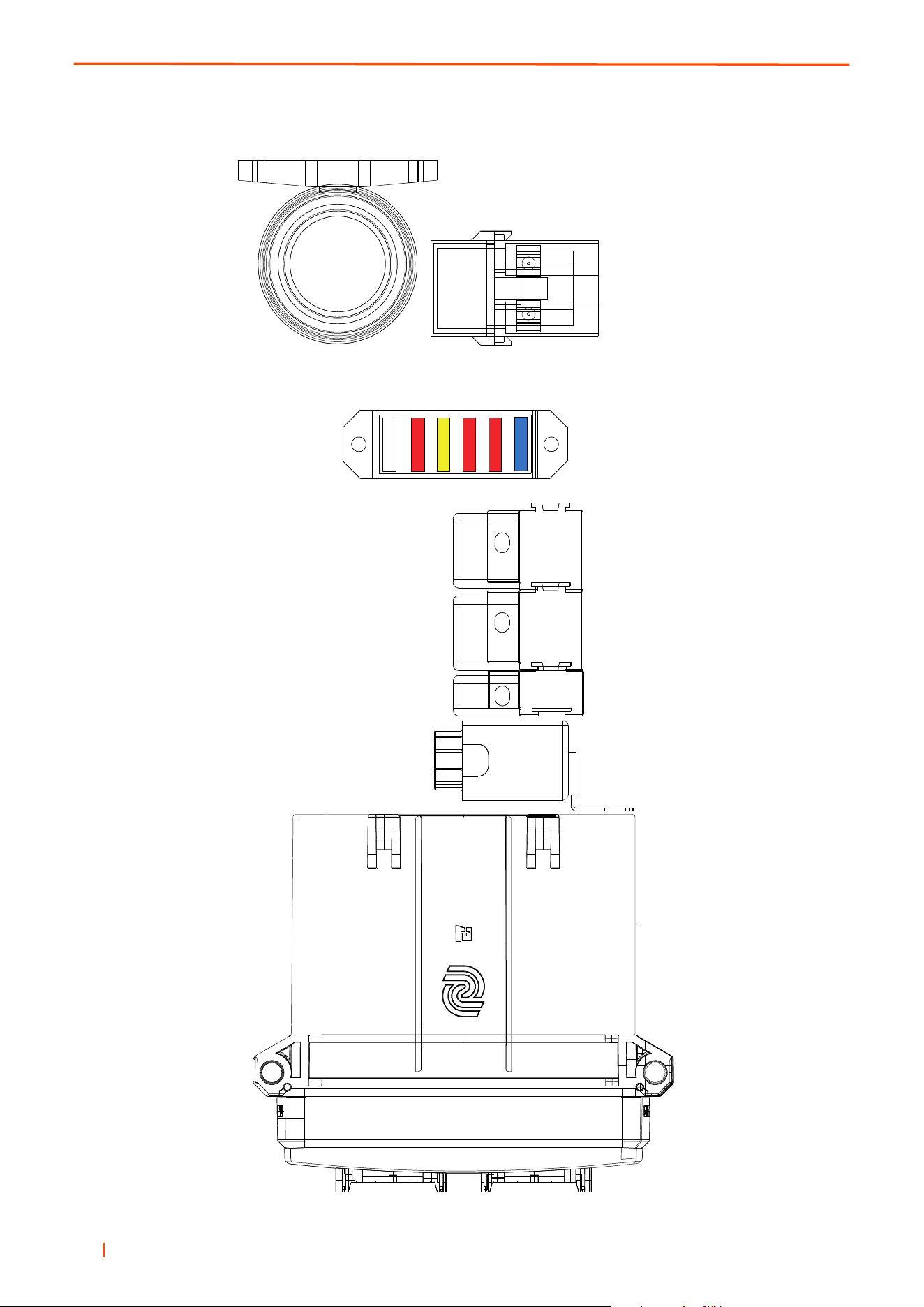
en 94
12 SCHEMATICS
12.1 ELECTRICAL FUSES & RELAYS _______________________________________
1
2
3
4
5
6
7
R4
R3
R2
R1
A
B

en 95
SCHEMATICS 12
12.2 FUSE AND RELAY IDENTIFICATION ____________________________________
Fuse Number Colour Amps Function
1 Accessory
2 Red 10 Air Seat
3 Yellow 20 Plus 1 Controller
4 Red 10 PTO Switch
5 Red 10 Accessory Socket
6 Blue 15 Working Lights
7 Orange 40 Glow Plugs (Diesel)
Relay Number Function
R1 Engine Stop Relay (Diesel)
R2 Starter (Gasoline Only)
R3 Glow Heater (Diesel Only)
R4 Starter (gasoline & Diesel)
Item Description
A Plus 1 Controller
B Audible Alarm

en 96
13 TORQUES
13.1 TORQUES __________________________________________________________
FINE PITCH METRIC THREADS COARSE PITCH METRIC THREADS
Dia
(mm)
Grade
4.6
Grade
4.8
Grade
8.8
Grade
10.9
Grade
12.9
Dia
(mm)
Grade
4.6
Grade
4.8
Grade
8.8
Grade
10.9
Grade
12.9
(Nm) (Nm) (Nm) (Nm) (Nm) (Nm) (Nm) (Nm) (Nm) (Nm)
6 0 0 0 0 0 6 5 6 12 17 21
8 12 16 32 45 54 8 11 15 30 42 51
10 24 31 63 88 106 10 22 30 59 84 100
12 42 57 113 159 191 12 39 52 104 146 175
14 67 90 179 252 302 14 62 82 165 232 278
16 103 137 274 385 462 16 96 129 257 362 434
20 209 279 557 783 940 20 188 251 502 706 847
22 281 375 750 1055 1266 22 256 341 683 960 1152
24 354 472 944 1327 1593 24 325 434 868 1220 1464
27 514 686 1371 1928 2314 27 476 635 1269 1785 2142
30 715 954 1908 2683 3219 30 646 862 1723 2424 2908
33 964 1286 2572 3616 4340 33 822 1097 2193 3084 3701
36 1196 1594 3189 4484 5381 36 1129 1506 3012 4235 5082
UNF THREADS UNC THREADS
Dia
(in)
Grade
A
Grade
S
Grade
T
Grade
V
Grade
X
Dia
(in)
Grade
A
Grade
S
Grade
T
Grade
V
Grade
X
(lbf. ft) (lbf. ft) (lbf. ft) (lbf. ft) (lbf. ft) (lbf. ft) (lbf. ft) (lbf. ft) (lbf. ft) (lbf. ft)
1/4 3.8 10.4 11.3 14.3 17.3 1/4 3.4 9.2 9.9 12.6 15.2
5/16 7.7 20.8 22.5 28.5 34.5 5/16 7 18.9 20.4 25.8 31.3
3/8 13.9 37.7 40.7 51.6 62.5 3/8 12.3 33.5 36.1 45.8 55.5
7/16 21.9 59.5 64.2 81.4 98.6 7/16 19.7 53.5 57.8 73.2 88.7
1/2 33.7 91.5 98.7 125 152 1/2 30.1 81.6 88 112 135
9/16 48.2 131 141 179 217 9/16 43.3 117 127 161 195
5/8 67.4 183 197 250 303 5/8 59.8 162 175 222 269
3/4 118 319 344 437 529 3/4 106 288 310 394 477
7/8 188 509 550 697 645 7/8 171 464 500 635 769
1 279 757 817 1036 1255 1 256 695 749 950 1152
1 1/8 405 1099 1186 1504 1823 1 1/8 363 984 1062 1347 1632
1 1/4 563 1529 1650 2093 2535 1 1/4 511 1387 1497 1899 2300
1 3/8 759 2061 2224 2821 3418 1 3/8 670 1820 1963 2490 3017

en 97
GUARANTEE 14
14.1 GUARANTEE _______________________________________________________
WARRANTY
Warranty is subject to specific terms and conditions, e.g. wearing parts, unapproved modifications, etc. are not
included. For a full set of warranty conditions, contact your local dealer or distributor.
SERVICE
A network of authorised Sales and Service dealers has been established and these details are available from
your supplier.
When service attention, or spares, are required for the machine, within or after the warranty period your supplier
or any authorised dealer should be contacted. Always quote the registered serial number of the machine. If any
damage is apparent when delivery is made, report the details at once to the supplier of the machine.
NOTICE
The use of components not provided by the manufacturer under this warranty or maintenance or repair that
is improperly or incorrectly performed may void this warranty.


United Kingdom
Ransomes Jacobsen Limited
West Road, Ransomes Europark, Ipswich, IP3 9TT
English Company Registration No. 1070731
T: +44 1473 270000 W: www.ransomes.com
Europe office
Ransomes Jacobsen France
3 Chemin des Silos
ZI du Chapitre
31100 Toulouse
T: +33 (0)5 34 47 86 40
North & South America
Jacobsen
1451 Marvin Griffin Road, Augusta,
Georgia 30906 - 3852, USA
W: www.jacobsen.com
1451 Marvin Griffin Road Augusta, Georgia 30906 - 3852, USA
Cert No. FS609275 Cert No. EMS609276 Cert No. OHS609277
OHSAS
18001
Occupational
Health & Safety
Management
ISO
14001
Environmental
Management
ISO
9001
Quality
Management
A SIGNATURE CUT, TRUSTED FOR OVER 100 YEARS
