EHVC513
Wi-Fi Touchscreen Thermostat
Quick Start Guide
2
Welcome
Installation
You can scan the QR code on the right to
get the installation video. Or follow the
Quick Start Guide to start installation.
For help and support, please contact

3
Safety Handling
WARNING: Failure to follow these safety notices could result in fire,
electric shock, other injuries, or damage to the Thermostat and other
property. Read all the safety notices below before using the Thermostat.
• Avoid high humidity or extreme temperatures.
• Avoid long exposure to direct sunlight or strong ultraviolet light.
• Do not drop or expose the unit to intense vibration.
• Do not disassemble or try to repair the unit on your own.
• Do not expose the unit or its accessories to ammable liquids, gases or
other explosives.
Welcome
1
The Wi-Fi Touchscreen thermostat makes it easier and smarter to control
your household temperature. With the help of zone sensors, you can
balance hot or cold spots throughout the home to achieve best comfort.
You can also schedule your thermostat working hours to match your plans.
This guide will provide you with an overview of the product and will help
you understand how to use it.
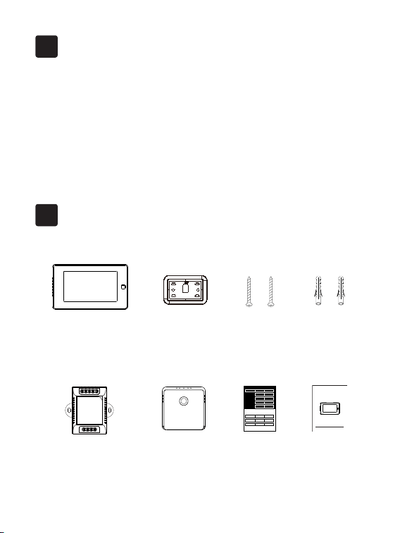
In the box
2
Wi-Fi Touchscreen Thermostat
C-wire Power module
(optional)
To Thermostat
RG YW
RGC YW
To Control Board
Remote Zone Sensor
(optional)
Wall Plate
User guide
Wi-Fi Touchscreen Thermostat
Quick Start Guide
2*Screws
2*Drywall plugs
Wire Tags
Label 1.
Label 2.
Thermostat
If you have a C
wire, you will not
need the label 2
below.
Control board
C C
RC
RC
RC
RC
RH
RH
R R
C C
S S
G G
R R
RC RC
RH RH Y2 Y2
Y/Y1 Y/Y1
Y/Y1 Y/Y1
W/W1 W/W1
W/W1 W/W1
W2 W2
O/B O/B
* *
G G
4
5
RC
RH G
C
Y1 Y2
W1
W2 O/B
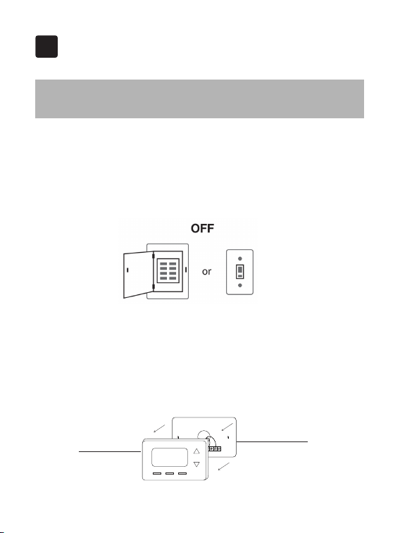
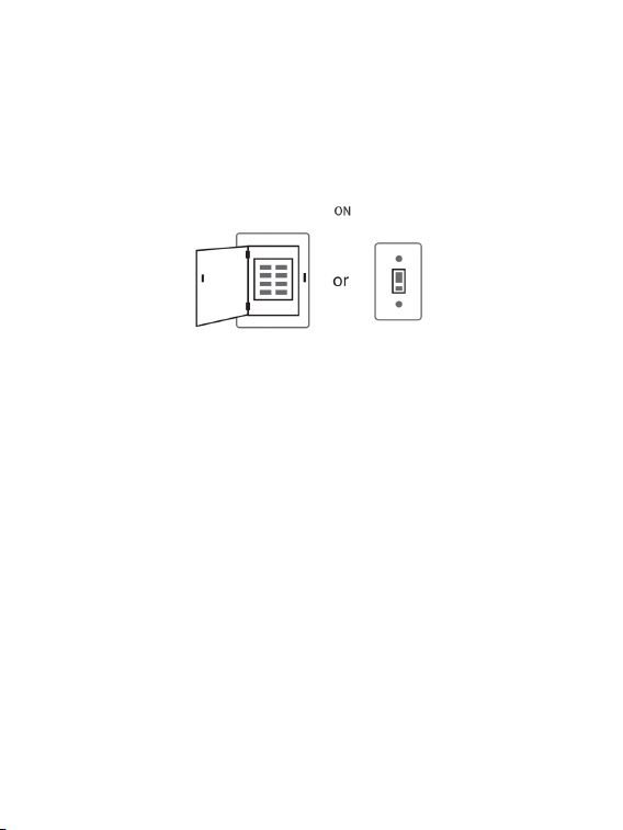
Step 1. Switch o your HVAC system
Before you start, please switch off your HVAC system to protect you and
avoid blowing a fuse. Wait a few minutes, then try to adjust the temperature
in your old thermostat to double check if the system is o.
Installation Guide
3
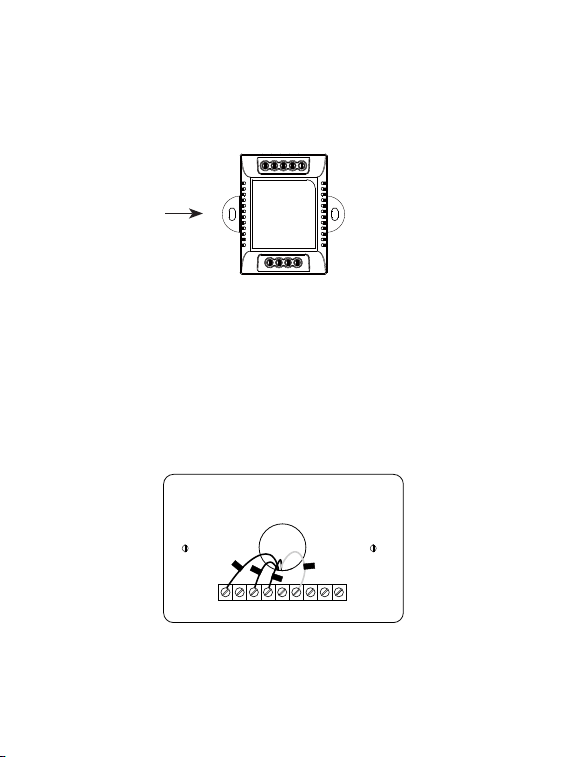
3-1 Removing your old thermostat
Step 2. Remove the old thermostat
Remove the old thermostat faceplate from the wall.
Do not remove
the wallplate
Old thermostat
Breaker box Switch
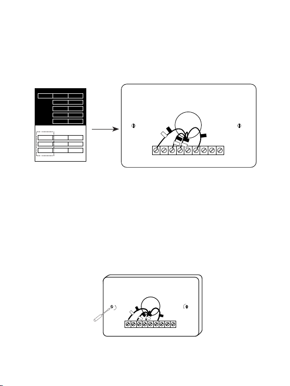
Step 4. Take a photo
Take a picture of the wires connected to the terminal of your old
thermostat. You may need to reference this photo later.
RC
RH G
C
Y1 Y2
W1
W2 O/B
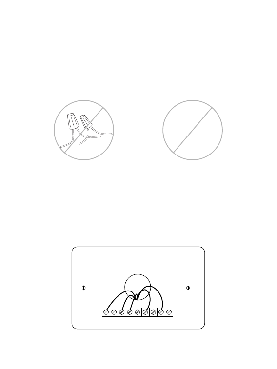
Step 3. Compatibility Check
If you find a thick wire with wire nuts on the backplate of the old
thermostat, or if the voltage of your old system is 120v or higher, it will
not be compatible with new thermostat. If none of the above, then please
proceed to the next step.
OR
120V
or
higher
6
7
RC
RH G
C
Y1 Y2
W1
W2 O/B
C
RC
G
W1
Y1
RC
RH G
C
Y1 Y2
W1
W2 O/B
C
RC
G
W1
Y1
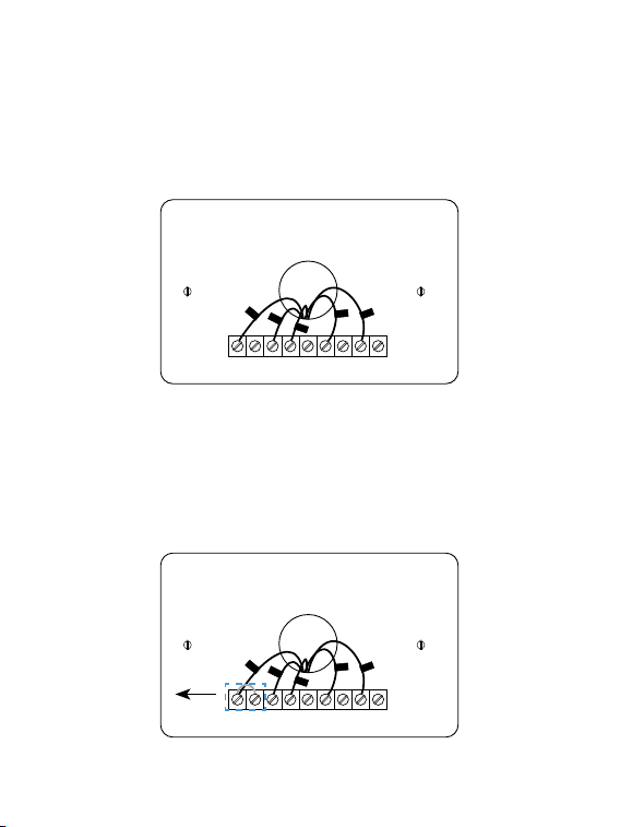
Step 5. Label the Wires with Tags
Label each wire on the wallplate with the tags (label 1) provided. Then
carefully disconnect the wires.
Note: If there are any jumper wires between Rh, Rc, or R terminals, do not
label them. New thermostat does not need jumpers. Remove them.
Remove
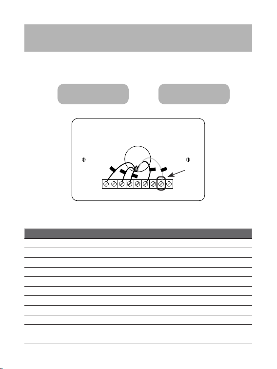
Terminal designation:
Terminals What it means
RC 24VAC primary for cooling
RH 24VAC primary for heating
C 24VAC common
W1 1st stage Primary heating relay / Aux heat
W2 2nd stage Secondary heating relay / Aux heat
Y1 1st stage Primary compressor contactor
Y2 2nd stage Secondary compressor contactor
G Fan relay
O/B Changeover valve for heat pumps
S
Optional Power Module terminal, combine signals from the Y
(cooling) and G (fan) wires into a single wire
Do you have a C wire connected to your old thermostat?
3-2 Connect wires
RC
RH G
C
Y1 Y2
W1
W2 O/B
RC
G
Y1
W1
C
YES → 3-2-1 NO → 3-2-2
8
9
3-2-1 Install the thermostat with a
C-wire
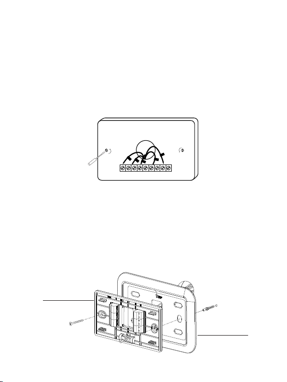
Step 1. Remove the wallplate
Unscrew the wallplate from the wall and gently pull it out to ensure the
wires do not fall back into the hole.
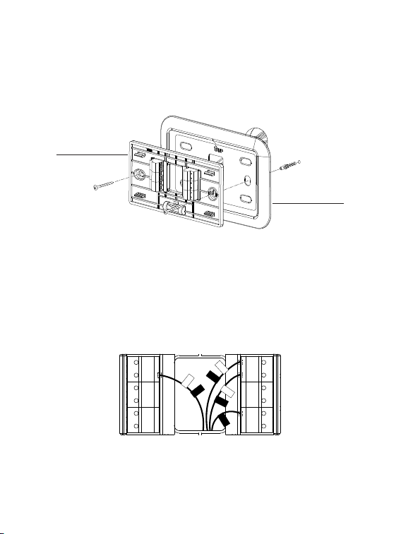
Step 2. Attach the base to the wall
Bundle and insert the wires through the hole of the wall plate and the base
of new thermostat, then attach the base to the wall with the screws.
RC
RH G
C
Y1 Y2
W1
W2 O/B
C
RC
G
W1
Y1
↑
↑
↑
↑
Wall plate
Base
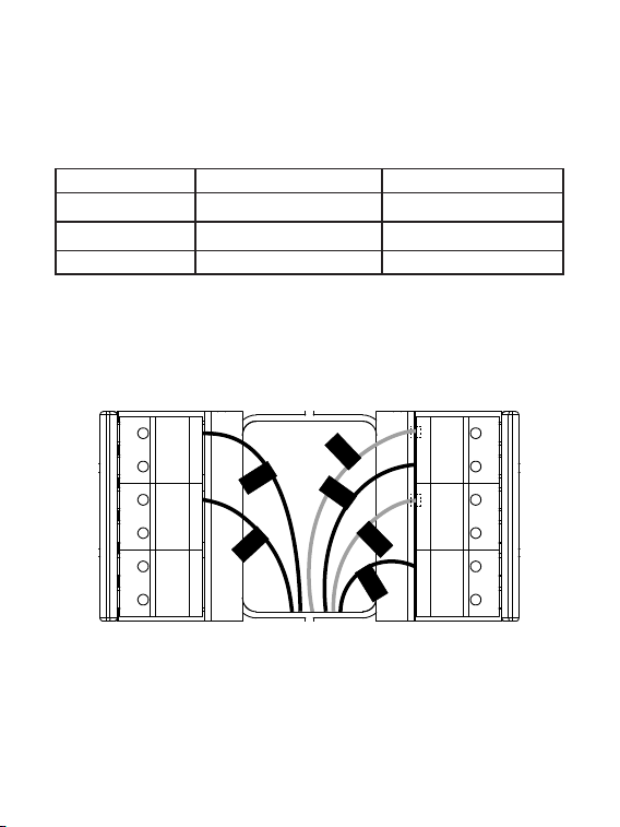
Step 3. Connect the wires
G
S
Y�
Y�
M�
M�
RC
C
RH
O/B
W�
W�
W�
RC
C
G
Y�
RH
Take a picture of the wires when you are nished. You may need to refer it
for the wirings in the setup wizard later.
• If you only have one R wire (That includes R, Rc, and Rh), connect it to Rc
terminal.
• If you have more than one R wire (That includes R, Rc, and Rh), connect
them as follows:
• Connect other wires to the corresponding terminals
Wires you have Wire to Rc Terminal Wire to Rh Terminal
Rc, Rh Rc Rh
Rc, R Rc R
Rh, R R Rh
10
11
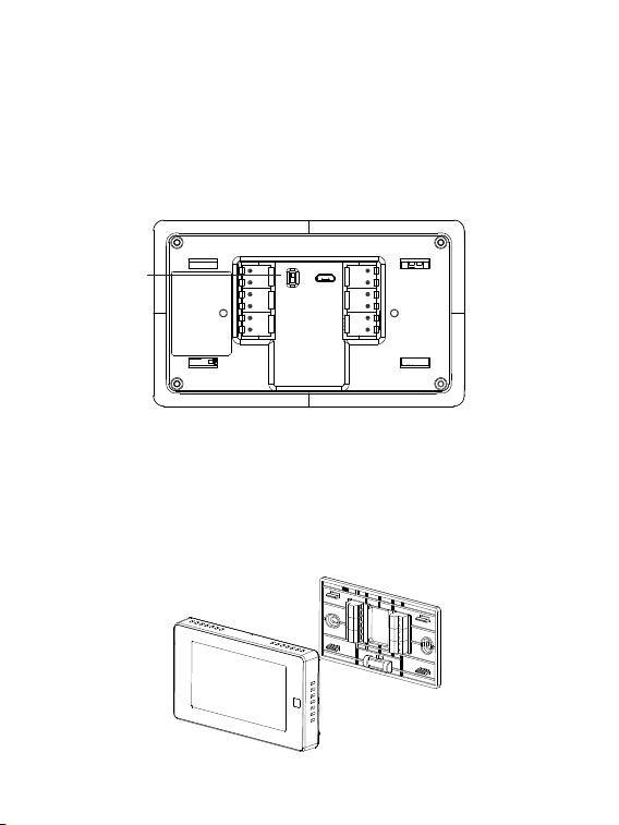
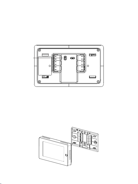
Step 4. DIP Switch
If you have connected more than one R wire(That includes R, Rc, and Rh)
to the wallplate, adjust the DIP switch on the back of the thermostat to
'Disconnect'. Otherwise, switch it to 'Connect'.
RC&RH
Connect
Disconnect
DIP switch
Step 5. Attach the faceplate to the base
Gently press the faceplate into the base until it clicks.
→
→
→
→
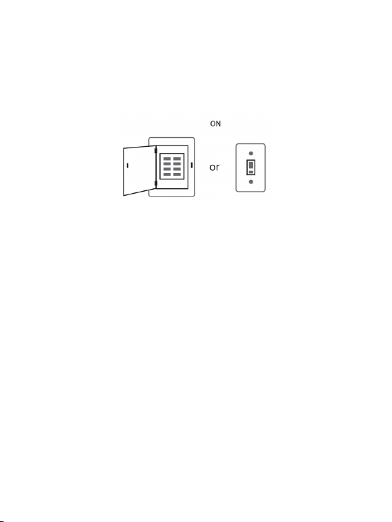
Step 6. Power on your system
Congratulation! The installation is finished. Please power on your HVAC
system.
Once powered up, the thermostat's screen will light up and display the
setup wizard. You can complete the following conguration according to
section 4.
Breaker box Switch
12
13
Power module requires your system to have the following 3
wires:
Y/Y1, G, and R (or Rc or Rh)
If you do not have these wires, your system may not be
compatible with the power module.
3-2-2 Install the thermostat without a
C-wire
(Optional)
To Thermostat
RG YW
RGC YW
To Control Board
RC
RH G
C
Y1 Y2
W1
W2 O/B
RC
G
Y1
W1
Power module
14
W
C G
Y R
Control Board
W
R
G
Y
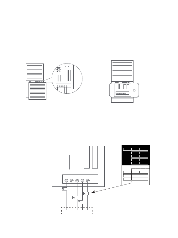
Step 1. Find the HVAC terminals
Find the control board of your HVAC system. Open your HVAC system's
cover and take a picture of the wires connected to the terminals of your old
thermostat. You may need to reference this photo later.
To thermostat
Step 2.
Label the wires
Label only the wires from the control board to your old thermostat with the
tags provided (label 2 control board).
W
C
G Y R
HVAC
Control Board
→
→
W C G Y R
Label 1.
Label 2.
Thermostat
If you have a C
wire, you will not
need the label 2
below.
Control board
C C
RC
RC
RC
RC
RH
RH
R R
C C
S S
G G
R R
RC RC
RH RH Y2 Y2
Y/Y1 Y/Y1
Y/Y1 Y/Y1
W/W1 W/W1
W/W1 W/W1
W2 W2
O/B O/B
* *
G G
15
R
Y
G
W
To Thermostat
RG YW
RGC YW
To Control Board
Control Board
W
R
G
Y
↓
W C G Y
R
To thermostat
Step 3. Disconnect the wires
Disconnect the W/W1, G, Y/Y1, R wires from the control board.
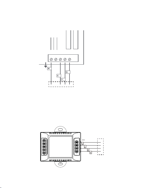
Step 4. Connect the wiring module
Reconnect these wires to the 4-terminal side of the power module. The
wires and corresponding terminals are shown below.
R → RC W/W1 → W G → C Y/Y1 → S
To thermostat
Power module
16
HVAC Control Board
W
C G
Y R
R
Y
G
W
To Thermostat
RG YW
RGC YW
To Control Board
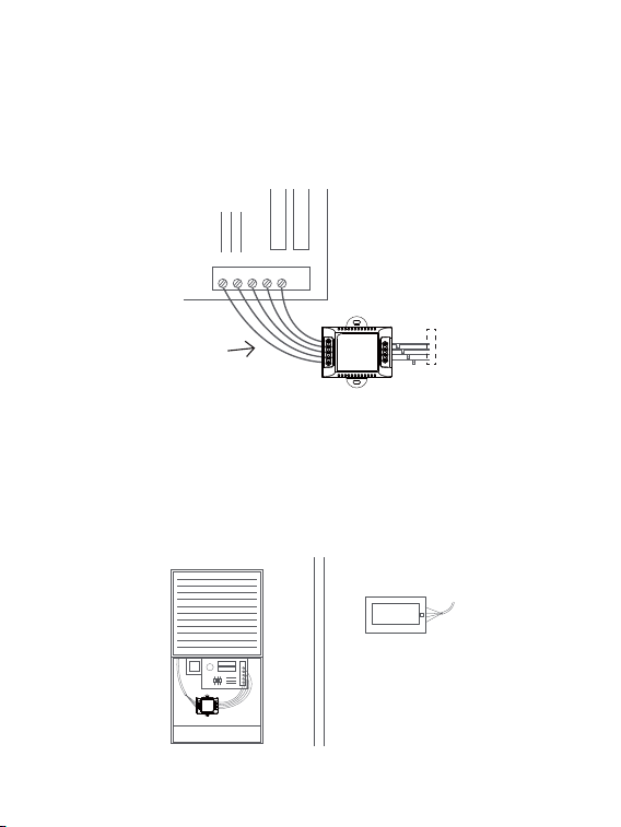
Step 6. Position the wiring module
The power module should be installed between your thermostat wiring and
your control board. Install it at the right position then close the HVAC cover
panel securely and return to your thermostat.
Step 5. Connect the wires
Generally, the control board will have W, C, G, Y and R terminals. Connect
the pre-wired side of the power module (5 terminals) to the corresponding
terminals on the HVAC control board.
To HVAC control board
To thermostat
To Thermostat
RG YW
R
GC YW
To Control Board
17
RC
RH G
C
Y1 Y2
W1
W2 O/B
RC
RC
G
C
S
W1
Y1
↑
↑
Step 8. Remove the wallplate
Unscrew the wallplate from the wall, gently pull it out and ensure the wires
will not fall back into the hole.
Step 7. Add new tags
Add new tags to the following tags to simplify your wiring:
R/RC/RH → RC G → C Y/Y1 → S
RC
RH G
C
Y1 Y2
W1
W2 O/B
RC
RC
C
G
W1
Y1
S
Label 1.
Label 2.
Thermostat
If you have a C
wire, you will not
need the label 2
below.
Control board
C C
RC
RC
RC
RC
RH
RH
R R
C C
S S
G G
R R
RC RC
RH RH Y2 Y2
Y/Y1 Y/Y1
Y/Y1 Y/Y1
W/W1 W/W1
W/W1 W/W1
W2 W2
O/B O/B
* *
G G
18
Step 9. Attach the base to the wall
Bundle and insert the wires through the hole of wall plate and the base of
new thermostat, then attach the base to the wall with the screws.
Step 10. Connect the wires
First, connect 3 wires as shown below:
RC, C, S
G
S
Y1
Y2
M1
M2
RC
C
RH
O/B
W1
W2
RC
RC
G
C
W1
Y1
S
↑
Then connect other wires to the corresponding terminal in the base. Take
a picture of the wires when you nished. You may need to refer it for the
wirings in the setup wizard later.
↑
↑
Wall plate
Base
19
Step 11. DIP Switch
If you have connected more than one R wire(That includes R, Rc, and Rh)
to the wallplate, adjust the DIP switch on the back of the thermostat to
'Disconnect'. Otherwise, switch it to 'Connect'.
Step 12. Attach the faceplate to the base
Gently press the faceplate into the base until it clicks.
→
→
→
→
RC&RH
Connect
Disconnect
DIP switch
20
Step 13. Power on your system
Congratulation! The installation is finished. Please power on your HVAC
system.
Breaker box
Switch
Once powered up, the thermostat's screen will light up and display the
setup wizard. You can complete the following conguration according to
section 4.
21
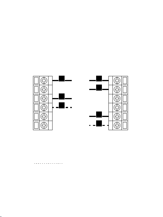
Wiring diagrams
Below are the wiring diagrams for common HVAC equipment.
Conventional heating and cooling system
G
S
Y�
Y�
M�
M�
C
RC
RH
O/B
W�
W�
G
C
Y�
W�
RH
W�
Y�
For 2-Stage heating/cooling system,
if applicable.
If you have connected more than one R wire(That includes R, Rc, and Rh)
to the wallplate, adjust the DIP switch on the back of the thermostat to
'Disconnect'. Otherwise, switch it to 'Connect'.
22
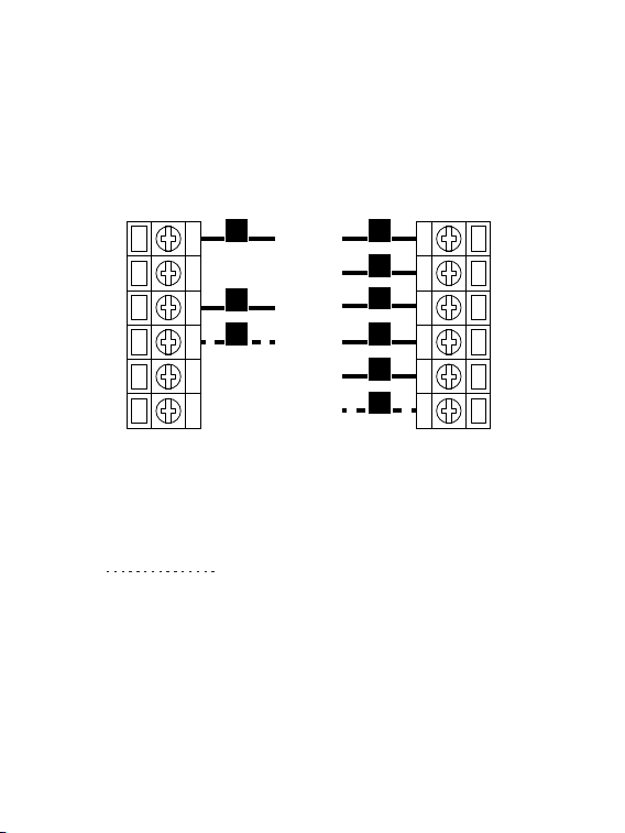
For 2-Stage heating/cooling system,
if applicable.
Heat pump (air or geothermal) with auxiliary heat
G
S
Y�
Y�
M�
M�
C
RC
RH
O/B
W�
W�
G
C
Y�
W�
RC
RH
O/B
W�
Y�
If you have connected more than one R wire(That includes R, Rc, and Rh)
to the wallplate, adjust the DIP switch on the back of the thermostat to
'Disconnect'. Otherwise, switch it to 'Connect'.
23
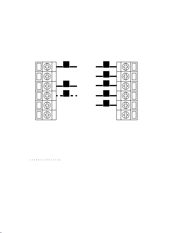
Heat Pump with Aux Heat or Emergency Heat
G
S
Y�
Y�
M�
M�
C
RC
RH
O/B
W�
W�
G
C
Y�
Aux/E
RC
RH
O/BY�
If you have connected more than one R wire(That includes R, Rc, and Rh)
to the wallplate, adjust the DIP switch on the back of the thermostat to
'Disconnect'. Otherwise, switch it to 'Connect'.
For 2-Stage heating/cooling system,
if applicable.
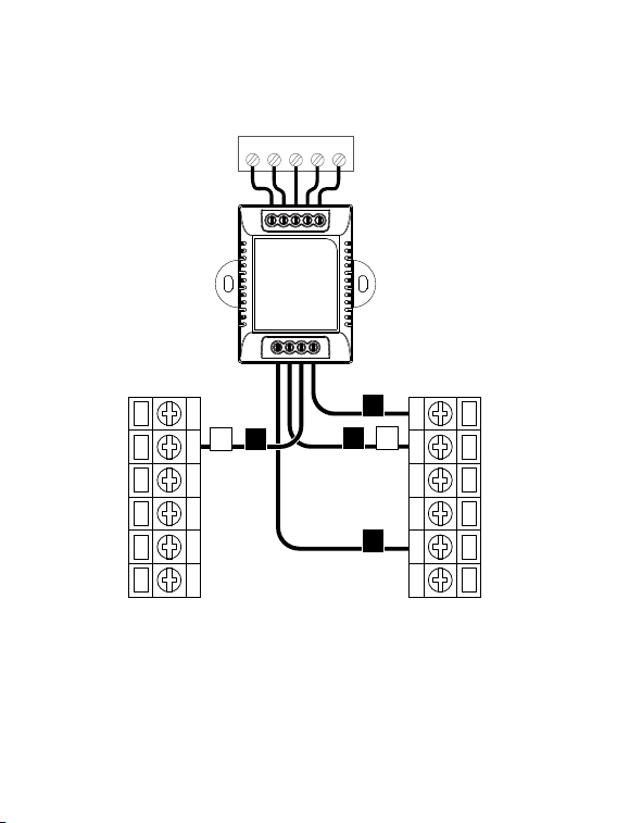
C-wire Power Module wiring
G
S
Y�
Y�
M�
M�
C
RC
RH
O/B
W�
W�
W�
G
C
RC
Y�S
Control Board
W
C
G Y
R
To Thermostat
RG YW
RGC YW
To Control Board
If you have connected more than one R wire(That includes R, Rc, and Rh)
to the wallplate, adjust the DIP switch on the back of the thermostat to
'Disconnect'. Otherwise, switch it to 'Connect'.
24
25
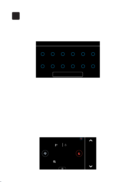
Select which terminals have wires connected to them on your new
thermostat.
After that, follow the wizard to complete the thermostat setup based on
your HVAC system.
1. Download the Smartlife app on App Store or Google Play.
2. Create an App account.
3. Make sure the Wi-Fi icon on thermostat home page is in unpaired state,
otherwise click the icon to reset the Network.
Setup
4
• Wiring
Next
RC
Y1
RH
Y2
C
W1
G
W2
S
M2
O/B
M1
Wi-Fi setup
Cool to
26.o
Follow Schedule
27.5
42%
?
12:00
FRI
←
26
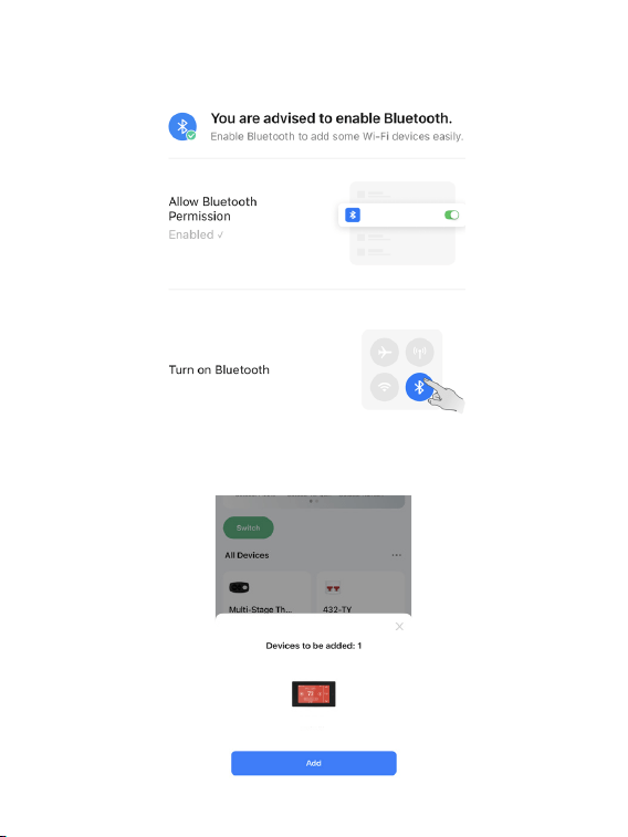
4. Turn on Bluetooth on your phone and allow Bluetooth permission of
Smartlife app.
5. Open the Smartlife app and the scanned devices will pop up
automatically. Follow the guidance of the App to add thermostat.
Thermostat
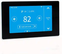
27
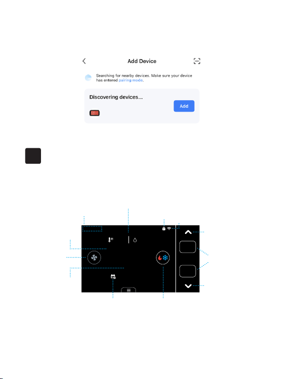
Main page
Meet Your Thermostat
5
Cool to
29.0
Heat to
16.0
42%
27.5
27.5
Follow Schedule
12:00
FRI
Date&Time
Locked
Wi-Fi
Fan
mode
Ave. temp icon
System
mode
Hold
mode
Avg
Target
temperature
Up
Down
Indoor
temperature
Outdoor Temperature
&Indoor Humidity
Ave. temp icon: Displayed when more than one sensor is involved in the
temperature calculation.
6. If no prompt box pops up automatically, please click the '+' on the top
right of the home page to add device. It will search nearby devices.
28
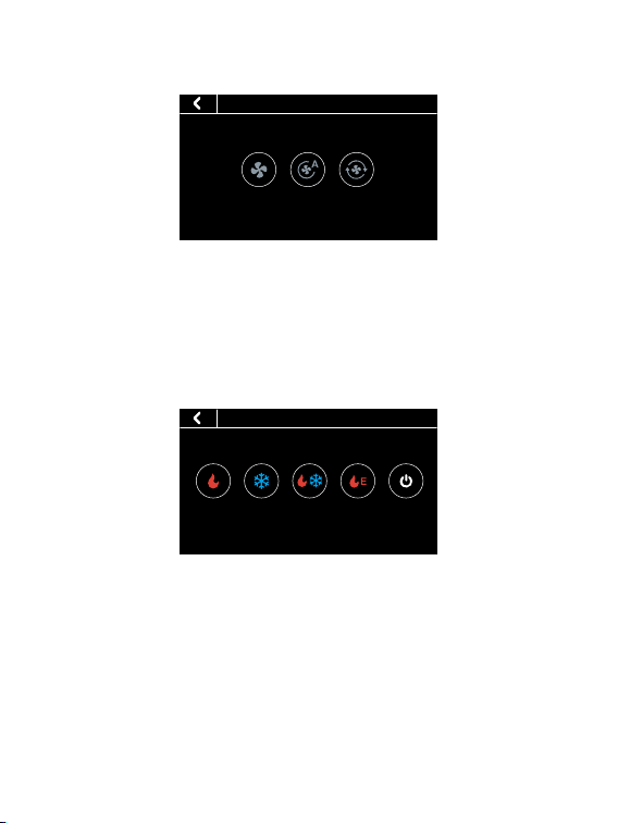
Fan mode
ON Auto Cir
• Fan
• On: Runs continuously
• Auto: Fan only runs while heating or cooling
• Cir: Runs at intervals to circulate indoor air
System mode
• HVAC
Heat Cool Auto Emergency
Heat
Off
• Heat: Heating only
• Cool: Cooling only
• Auto: Automatic control of heating and cooling based on ambient
temperature
• Emergency Heat: In this mode the thermostat will only call backup
system
• O: Turn the HVAC system o
29
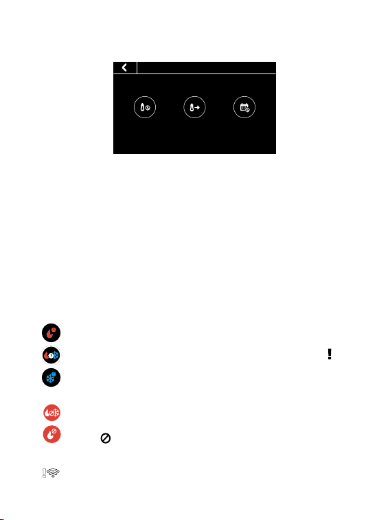
Hold mode
System or network alerts
• Hold
Follow
Schedule
Temporary
Hold
Permanent
Hold
• Temporary Hold: Hold the current target temperature until the next
scheduled activity begins.
• Permanent Hold: Hold the current target temperature until you
manually cancel it
• Follow Schedule: Follows the settings of schedule table to adjust the
indoor temperature.
The thermostat is connected to the router, but the router is
not connected to the network
When the outdoor temperature is higher than the 'AUX Heat
Max Outdoor Temp' you set, the icon on system mode will
display and the AUX Heat will be turned o automatically.
When the outdoor temperature is below the 'Compressor Min
Outdoor Temp' you set, the icon on system mode will display
and the compressor will be turned o automatically.
30
6
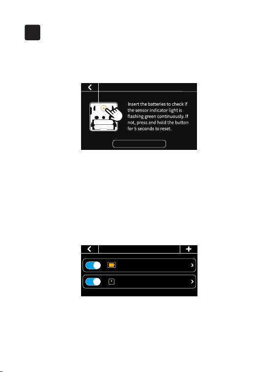
1.How to pair the thermostat with Remote Zone Sensors?
1. Click the '+' button at the top right of the interface in 'Menu' -> 'Sensors'
on the thermostat and tap 'Next'.
2. Remove the sensor's back cover and insert the batteries to check if the
sensor indicator light is ashing green continuously.
3. If not, press and hold the button on the back of the sensor for 5 seconds
to reset.
Now you can set the participation period of the sensor. During this period,
the thermostat will take the average temperature of all the sensors that
recently detected motion as the indoor temperature on the main screen.
FAQ
· Sensors
Thermostat ��.�/Occupied
My Sensor ��.�/Occupied
Tip: During sleep time, the sensor enabled during this period doesn't
care about occupancy, it will always participate in the calculation of the
average temperature. When you change the setting of sensor, the indoor
temperature on the main screen will update in 2 minutes.
Next
Add sensor
31
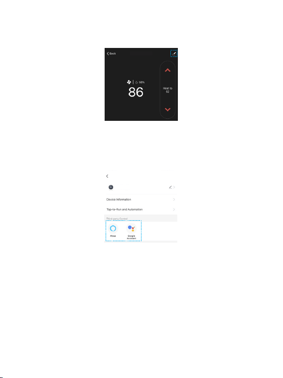
2.Enable voice control
←
←
Tap ''Device management'' at the top right of the control page, then link
your Alexa/Google account.
Voice Support:
1. Ask about the current temperature in Heat/Cool/Auto mode.
"Alexa/OK Google, what's the temperature of [thermostat name]"
"Alexa/OK Google, what's the [thermostat name] temperature?"
"Alexa/OK Google, ask [thermostat name] the temperature"
2. Change the temperature in Heat/Cool/Auto mode.
"Alexa/OK Google, set [thermostat name] to [target temperature]"
Thermostat
Thermostat

32
"Alexa/OK Google, raise/lower the thermostat temperature by [number]"
"Alexa/OK Google, raise/lower the [thermostat name] temperature by
[number]"
"Alexa/OK Google, increase/decrease the [thermostat name] temperature"
"Alexa/OK Google, increase/decrease [thermostat name] by [number]"
"Alexa/OK Google, make it cooler in [thermostat name]"
"Alexa/OK Google, make it warmer in [thermostat name]"
Note: If you change the temperature by voice on auto mode. It will
maintain 3 degrees dierence and keep the new temperature as the mid-
point.
For example:
- Thermostat is currently set to 17 degrees for heating and 30 degrees for
cooling.
- You ask Alexa/Google to set the thermostat to 26 degrees.
- It will turn to 24.5 degrees for heating and 27.5 degrees for cooling, using
the 26 degrees as the mid point and maintaining 3 degrees difference
between the heating and cooling target temperature.
3. Change System Mode
"Alexa/OK Google, set [thermostat name] to Heat/Cool/Auto mode"
"Alexa/OK Google, switch [thermostat name] to Heat/Cool/Auto mode"
"Alexa/OK Google, switch to Heat/Cool/Auto mode in the [thermostat
name]"
