EHVC523
WiFi 24VAC Thermostat
Quick Sta Guide
2
Impoant Information
FAILURE TO FOLLOW THESE SAFETY INSTRUCTIONS
COULD RESULT IN FIRE, ELECTRIC SHOCK, OR OTHER
INJURY OR DAMAGE.
In some regions, a professional installation may be necessa. Check your
local regulations and building codes before undeaking any electrical work,
as permits and/or professional installation might be legally required.
Before staing installation, turn o the power to the installation area at your
circuit breaker or fuse box. Always handle electrical wiring with care to avoid
the risk of electrical shock or equipment damage.
Install your device in a location that is away from heat sources and direct
sunlight to prevent temperature fluctuations, which could affect the
accuracy of temperature readings and overall device performance. Avoid
placing your device near water or in areas with high humidity.
For help and support, please contact
3
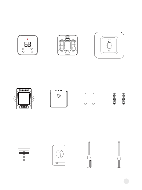
In the box
Wi-Fi
Thermostat
C-wire
Adaptor
(optional)
Remote
Zone Sensor
(optional)
Trim PlateBackplate
User Guide Phillips
screwdriver
Flat head
screwdriver
Screws
(x2)
Dwall Plugs
(x2)
Wire Labels
To Thermostat
RG YW
RGC YW
To Control Board
4
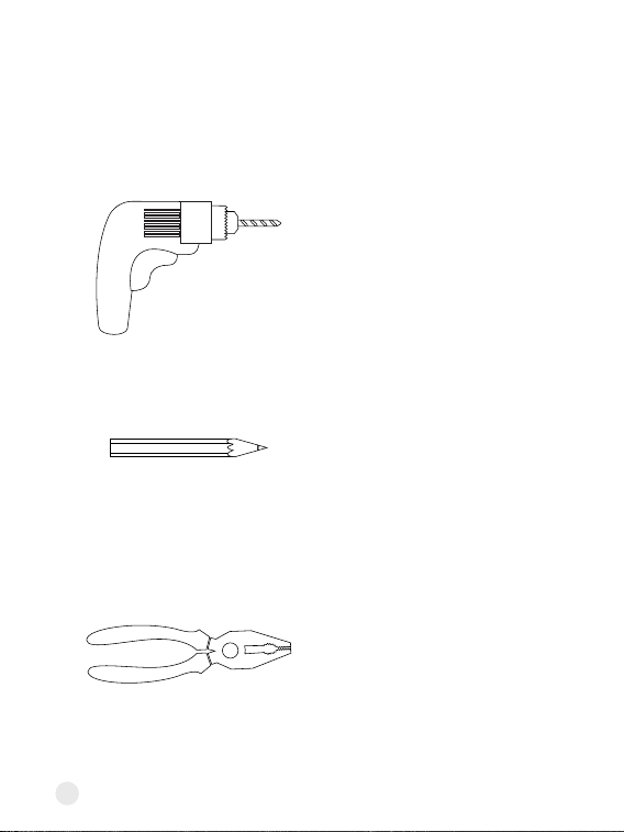
A pencil
Pliers and wire strippers
A drill with a 3/16-inch drill bit
These tools will help with installation
5
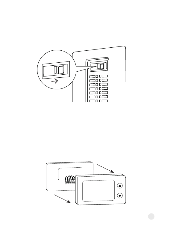
Step 1. Turn o the power
Locate the power switch for the HVAC system and turn it o. This step is
impoant for your safety and the safety of your home.
Once the power is o, t adjusting your old thermostat to double check that
the system is o.
Step 2. Remove your old thermostat faceplate
Some faceplate can be easily pop o, while others require a screwdriver.
ON
OFF
6
Step 3. Compatibility Check
A. High Voltage
or
or
B. C-wire
If you see any of these indicators on the back of your old thermostat, it
indicates that your system is high voltage, which may not be compatible.
• The thermostat requires a C wire for power. Check if there is a wire
connected to the C terminal on your old thermostat.
• If you don't have a C wire, you will need the following 3 wires on your old
thermostat to install the C-wire Adaptor to power new thermostat: Y/Y1, G,
and R (or Rc or Rh)
If you have neither a C wire nor the three required wires mentioned above,
then your system is incompatible.
110VAC
120VAC
240VAC
L1 L2
RC
RH G
C
O/B
7
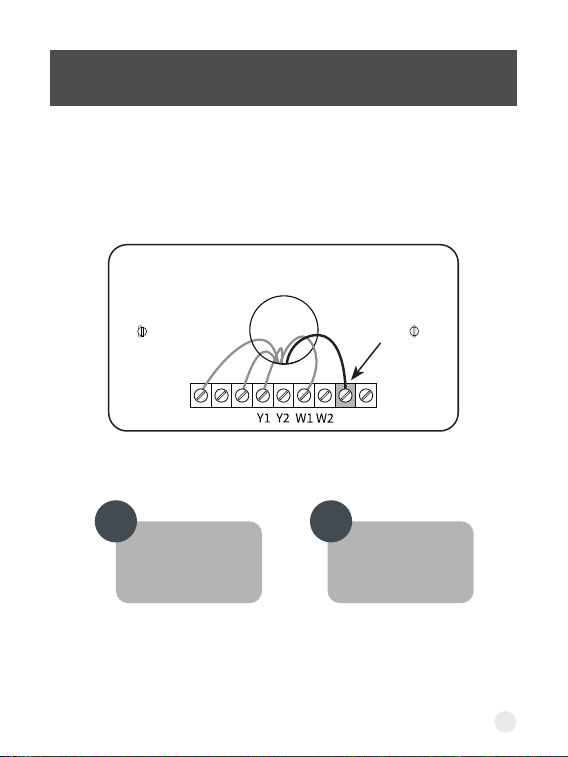
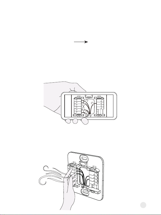
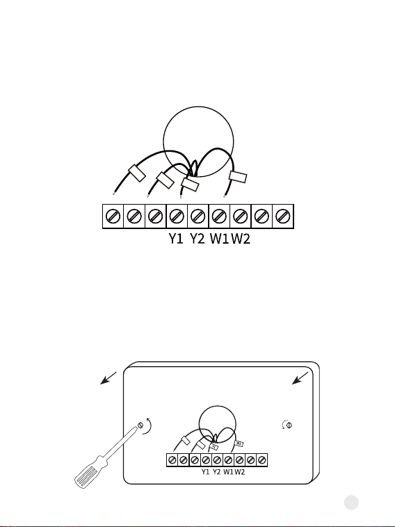
Step 4. Take a photo of your old wiring
It's impoant to have a photo of your old wiring, just in case you need to
return the wiring to the way it was before.
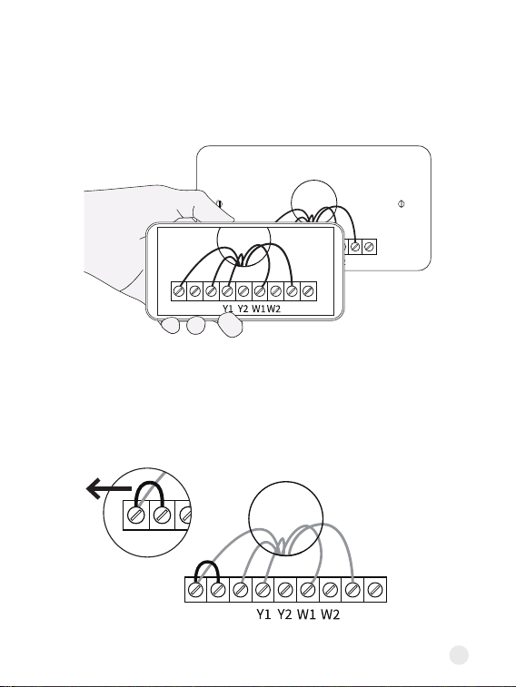
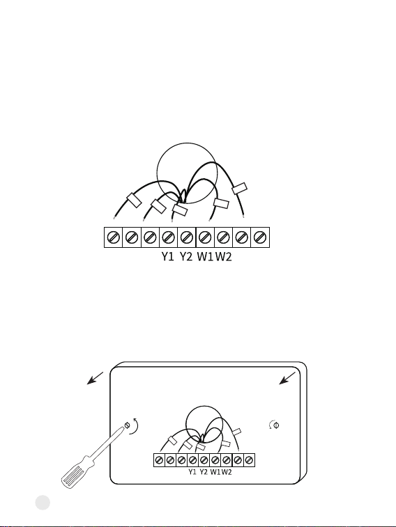
Step 5. Remove all jumper wires
Some systems have sho wires connecting two terminals. One of the two
terminals may not have a wire coming trom the wall. Remove all jumper
wires. Be careful not to remove regular wires coming from the wall.
RC
RH G
C
O/B
RC
RH G
C
O/B
RC
RH G
C
O/B
RC
RH G
C
O/B
8
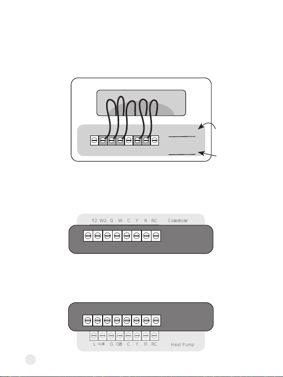
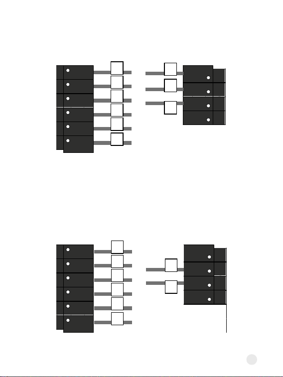
Step 6. Check which set of labels you will be using
Some thermostats have 2 sets of terminal labels, one for heat pump and one
for conventional. If you only have one set of labels, please skip this step and
jump to page 10.
• If your system has a heat pump, please use the heat pump wire labels or
the set of wires that includes the "O/B" label.
• If your system does not have a heat pump, please use the conventional
wire labels or the set of wires without the "O/B" label.
Y2
L
W2
AUX/E
G
G
W
O/B
C
C
Y
Y
R
R
RC Conventional
Heat Pump
RC
Y2
L
W2
AUX/E
G
G
W
O/B
C
C
Y
Y
R
R
RC Conventional
Heat Pump
RC
L
AUX/E
G O/B C Y R
Heat Pump
RC
Y2
L
W2
AUX/E
G
G
W
O/B
C
C
Y
Y
R
R
RC conventional
Heat Pump
RC
Y2 W2 G W C Y R RC Conventional
9
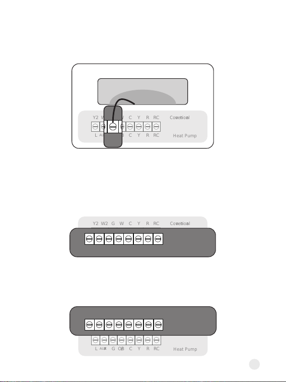
• If it is orange, please use the heat pump wire labels or the set of wires
that includes the "O/B" label.
• If it is white, please use the conventional wire labels or the set of wires
without the "O/B" label.
You can also identify it by the colors of wire with W and O/B labels.
Y2
L
W2
AUX/E
G
G
W
O/B
C
C
Y
Y
R
R
RC Conventional
Heat Pump
RC
L
AUX/E
G O/B C Y R
Heat Pump
RC
Y2
L
W2
AUX/E
G
G
W
O/B
C
C
Y
Y
R
R
RC conventional
Heat Pump
RC
Y2 W2 G W C Y R RC Conventional
Y2
L
W2
AUX/E
G
G
W
O/B
C
C
Y
Y
R
R
RC Conventional
Heat Pump
RC
W
O/B
10
Special labels:
If your old thermostat has wires connected to the following terminals, you
need to pay special attention when tagging them:
Terminal TerminalLabels Labels
W2/Aux
W2/Aux
W1
W2
W1
W2
Aux or Aux1
Aux2
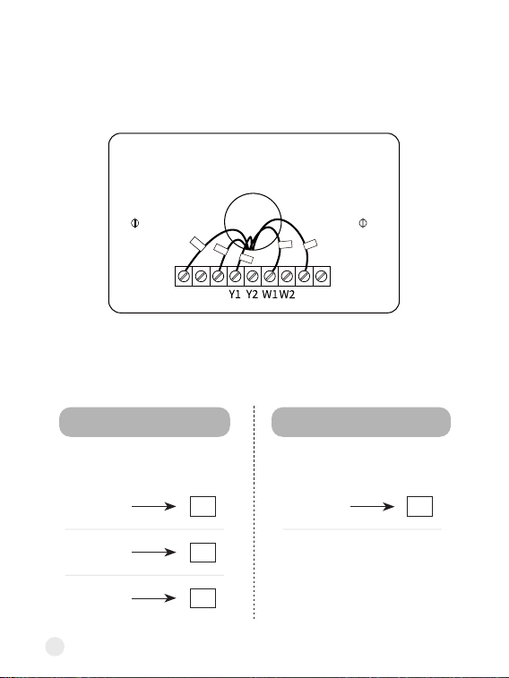
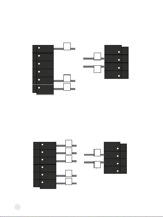
Step 7. Label your wires
Use the provided Wire Labels (White background) to tag each wire
accordingly. If you have two sets of terminal labels, please select the correct
one.
If you are Heat Pump system If you are Conventional system
RC
RH G
C
O/B
Rc
G
Y�
W�
C
11
Do you see any wire connected to the C terminal on
your old thermostat?
CHECKPOINT: C-WIRE
Continue to the
NEXT PAGE
Go to PAGE 18
YES NO
RC
RH G
C
O/B
12
Install the thermostat with a C wire
Step 8. Disconnect wires
Loosen each terminal and disconnect the wires from your old thermostat.
Don't let your wiring fall back into the wall after you disconnect them.
Step 9. Remove your old wall plate
Unscrew the old thermostat from the wall. If your old thermostat has a trim
plate, remove it too. You may want to wrap the wires around a pencil so they
don't fall back into the wall.
RC
RH G
C
O/B
RC
RH G
C
O/B
Rc
G
Y1
W1
C
Rc
G
Y1
W1
C
13
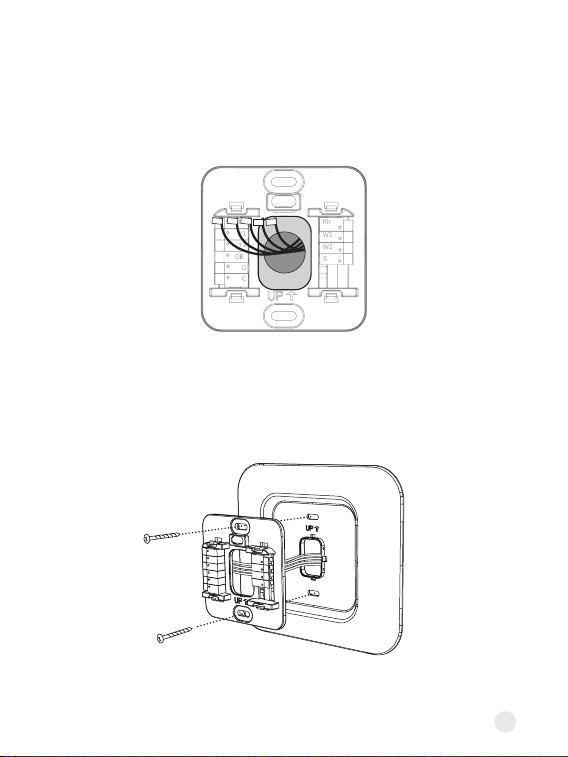
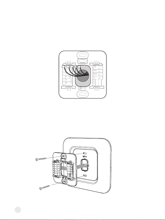
Step 10. Pull the wires through the backplate
Mark where the screws will go. Use the bubble level to make sure the
thermostat is straight. If you need to drill new holes in your wall, remove the
backplate before doing so.
Step 11. Attach the backplate to the wall
Secure your new thermostat's backplate to the wall by using the included
anchors and screw. You can drill a hole for the dwall anchors with 3/16'
drill bit.
Optional: use the trim plate to cover screw holes or gaps left over from your
old thermostat's installation.
Rc
Y1
Y2
O/B
G
C
Rh
W1
W2
S
Rc
Y1
Y2
O/B
G
C
Rh
W1
W2
S
14
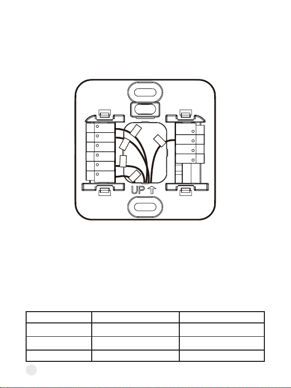
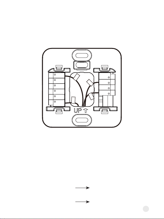
Step 12. Connect the wires
Press the terminal block levers down to insert each labelled wire to the
matching slot in your backplate. You can refer to the wiring diagram on page
29
Tug on the wires gently to ensure they are secured. After all the wires are
inseed, tuck them neatly back into the wall.
Special wires:
• If you have more than one R wire (That includes R, Rc, and Rh), connect
them as follows:
Wires you have Wire to Rc Terminal Wire to Rh Terminal
Rc, Rh Rc Rh
Rc, R Rc R
Rh, R R Rh
Rc
Y1
Y2
G
O/B
C
Rh
W1
W2
S
W1
Rc
Y1
G
C
15
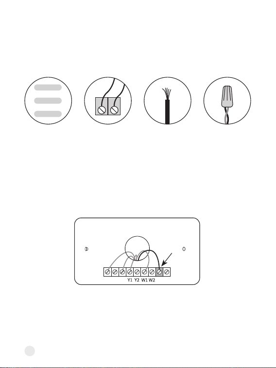
W2 terminalE wire
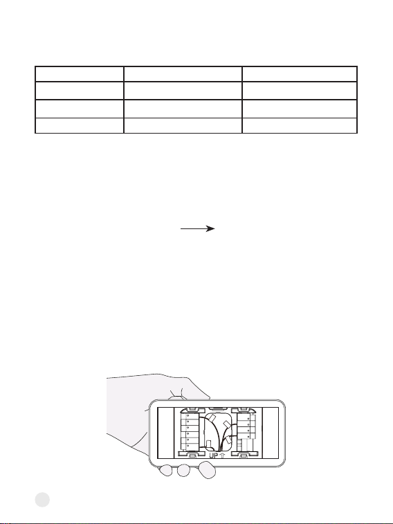
Step 13. Take a photo of your new wiring
It's impoant to have a photo of your new wiring. You will need it later when
setting the thermostat.
Step 14. Check for air drafts
Air drafts can aect temperature readings. If you feel a draft, seal the hole in
the wall.
• If you only have one R wire (That includes R, Rc, and Rh), connect it to Rc
terminal.
• If you have E wire (Emergency Heat)
Rh
W1
W2
S
Rc
Y1
Y2
G
O/B
C
Rh
W1
W2
S
W1
Rc
Y1
G
C
16
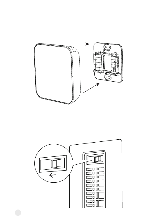
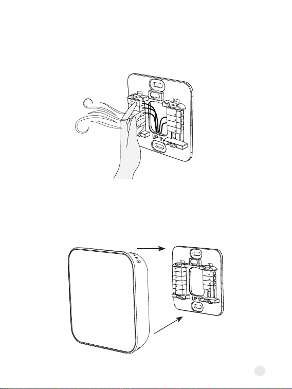
Step 15. Attach the thermostat faceplate
Gently press your Thermostat faceplate onto the backplate until it clicks into
place.
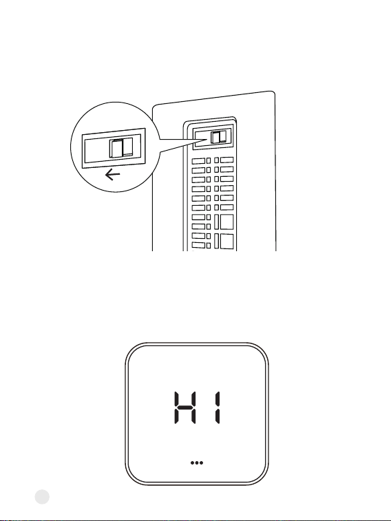
Step 16. Power on your system
Back to your power switch to turn your HVAC system's power back on.
ON
OFF
17
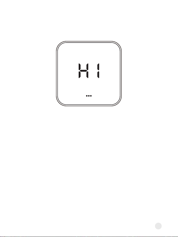
Once powered up, the thermostat's screen will light up and display 'Hi'.
Please go to page 34 to set up the thermostat.
18
Install the thermostat without a C wire
(Optional)
Your wiring requires a C-wire Adaptor
If you don’t have it, please contact the seller.
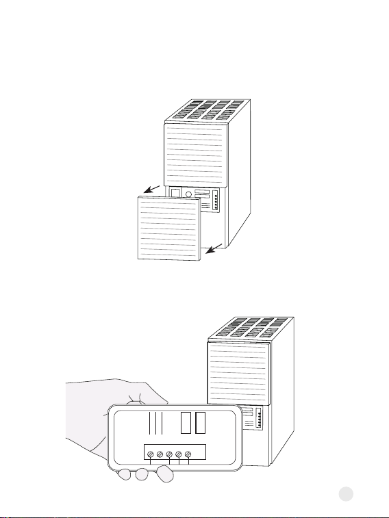
Step 8. Go to your HVAC system
Take your C-wire Adaptor, wire labels, screwdriver, your smartphone, and
go to your HVAC system. Most of these are located in basements, attics, or
garages.
If your system is controlled by more than one thermostat, it may be a zoned
system. Remove the cover from your zone panel instead.
To Thermostat
RG YW
RGC YW
To Control Board
19
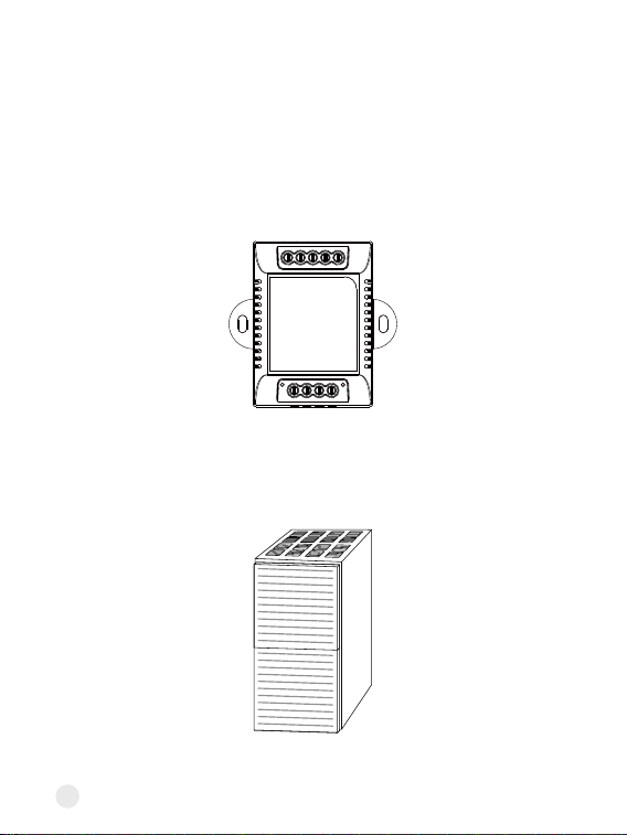
Step 9. Remove the cover
Look for screws or tabs to remove the cover to find the control board. It
will have wires with the same terminal labels and colors as your thermostat
wiring.
Step 10. Take a photo of your wiring
Take a photo of the wires connected to the terminals of the control board.
W C G Y R
20
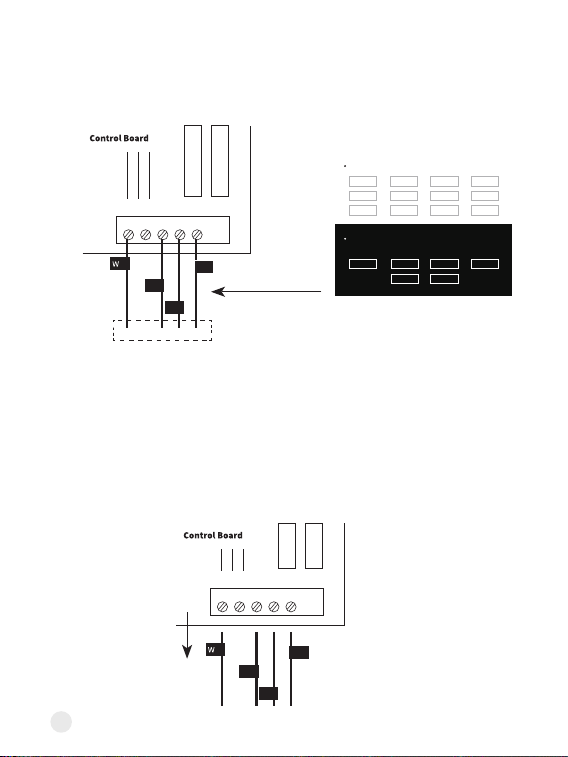
Step 11.
Label the wires on control board
Use the included wire labels (Black background) to tag 4 wires going to
your thermostat: R (or Rc or Rh), Y/Y1, G, W/W1
Note:
If there are more than one wire connected to one terminal, only label
the wire coming from the thermostat.
Step 12. Disconnect the wires
Use the screwdriver to loosen the screws holding the wires you labelled to
the control board. Do not disconnect any other wires.
W
W
C
C
G
G
Y
Y
R
R
R
R
G
G
Y
Y
To thermostat
Label the wires at your thermostat.
Label the wires at your control board.
You might need these if you are installing with a Power Module.
R R
R R Rc Rc Rh Rh G G
W2 W2 G G
C CY2 Y2
W
or
W1
W
or
W1
Y
or
Y1
Y
or
Y1
O/B O/B E E S S
Rc Rc
Rh Rh
21
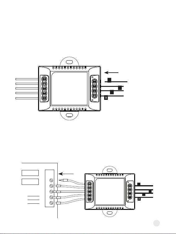
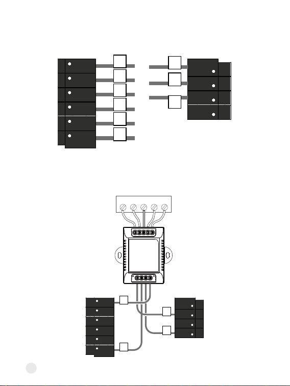
Step 13.
Connect labelled wires to the C-wire Adaptor
One at a time, connect the wires with matching labels to each terminal on
Adaptor. Once all wires are connected, gently tug each one to ensure they're
secure.
Step 14.
Connect the Adaptor to the control board
Connect the 5 white Adaptor wires to the corresponding terminal on the
control board.
Y
R
To Thermostat
RG YW
RGC YW
To Control Board
G
HVAC Control Board
W
C
G
Y
R
Y
R
To Thermostat
RG YW
RGC YW
To Control Board
G
W C
G
Y
R
22
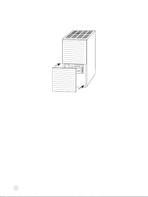
Step 15. Close the cover panel
Make sure you close the cover panel securely and return to your thermostat.
Note: Most HVAC systems have a safety switch will not start if the cover
panel is not secure.
23
Step 16. Disconnect wires
Loosen each terminal and disconnect the wires from your old thermostat.
Don't let your wiring fall back into the wall after you disconnect them.
Step 17. Remove your old wall plate
Unscrew the old thermostat from the wall. If your old thermostat has a trim
plate, remove it too. You may want to wrap the wires around a pencil so they
don't fall back into the wall.
RC
RH G
C
O/B
Rc
G
Y�
W�
RC
RH G
C
O/B
Rc
G
24
Step 19. Attach the backplate to the wall
Secure your new thermostat's backplate to the wall by using the included
anchors and screw. You can drill a hole for the dwall anchors with 3/16'
drill bit.
Optional: use the trim plate to cover screw holes or gaps left over from your
old thermostat's installation.
Rc
Y1
Y2
O/B
G
C
Rh
W1
W2
S
Step 18. Pull the wires through the backplate
Mark where the screws will go. Use the bubble level to make sure the
thermostat is straight. If you need to drill new holes in your wall, remove the
backplate before doing so.
Rc
Y1
Y2
O/B
G
C
Rh
W1
W2
S
25
Step 20. Connect the wires
Press the terminal block levers down to insert each labelled wire to the
matching slot in your backplate. You can refer to the wiring diagram on page
29
Tug on the wires gently to ensure they are secured. After all the wires are
inseed, tuck them neatly back into the wall.
C terminal
S terminal
G wire
Y/Y1 wire
Special wires:
• The C-wire Adaptor provides power to thermostats without a C-wire by
extending power capabilities using existing wires:
Rc
Y1
Y2
G
O/B
C
Rh
W1
W2
S
W1
Rc
Y1
G
26
Step 21. Take a photo of your new wiring
It's impoant to have a photo of your new wiring. You will need it later when
setting the thermostat.
W2 terminalE wire
• If you have E wire (Emergency Heat), connect them as follows:
• If you have more than one R wire (That includes R, Rc, and Rh), connect
them as follows:
Rc
Y1
Y2
G
O/B
C
Rh
W1
W2
S
W1
Rc
Y1
G
• If you only have one R wire (That includes R, Rc, and Rh), connect it to Rc
terminal.
Wires you have Wire to Rc Terminal Wire to Rh Terminal
Rc, Rh Rc Rh
Rc, R Rc R
Rh, R R Rh
27
Step 22. Check for air drafts
Air drafts can aect temperature readings. If you feel a draft, seal the hole in
the wall.
Step 23. Attach the thermostat faceplate
Gently press your Thermostat faceplate onto the backplate until it clicks into
place.
Rh
W1
W2
S
28
Once powered up, the thermostat's screen will light up and display 'Hi'.
Please go to page 34 to set up the thermostat.
Step 24. Power on your system
Back to your power switch to turn your HVAC system's power back on.
ON
OFF
29
Wiring diagrams
Thermostat Connectors:
Terminals What it means
Rc 24VAC power from cooling transformer
Rh 24VAC prima for heating
C 24VAC common
W1
1st stage Prima heating relay in conventional system
/ Auxilia or Alternative 1st stage heat in heat pump
system
W2
2nd stage Seconda heating relay in conventional
system / Auxilia or Alternative 2nd stage heat in heat
pump system / Emergency heat
Y1 1st stage Prima compressor contactor
Y2 2nd stage Seconda compressor contactor
G Fan relay
O/B Changeover valve for heat pumps
S
Optional Adaptor terminal, combine signals from the Y
(cooling) and G (fan) wires into a single wire
30
Conventional 2 Stage Heating
Conventional 2 Stage Heating, 2 Stage Cooling
RC
Y1
Y2
O/B
G
C
R
h
W1
W2
SS
C
G
W1
W2
Rh
RC
Y1
Y2
O/B
G
C
R
h
W1
W2
SS
C
G
W1
Y1
Y2
W2
R
Below are the wiring diagrams for common HVAC equipment.
31
2 Stage Heat Pump with 2 Stage Aux Heat
RC
Y1
Y2
O/B
G
C
R
h
W1
W2
SS
C
G
O/B
Y2
Y1
W1
W2
Rc
Rh
2 Stage Heat Pump with Aux Heat and Emergency Heat
RC
Y1
Y2
O/B
G
C
R
h
W1
W2
SS
C
G
O/B
Y2
Y1
E
W1
Rc
32
Dual Fuel - 2 Stage Heat pump, 2 Stage Heat
C-wire Adaptor wiring
RC
Y1
Y2
O/B
G
C
R
h
W1
W2
SS
C
G
O/B
Y2
Y1
W1
W2
Rc
Rh
RC
Y1
Y2
O/B
G
C
R
h
W1
W2
SS
G
Y1
W1
To Thermostat
RG YW
Rc
Control Board
W
C
G Y
R
RGC YW
To Control Board
33
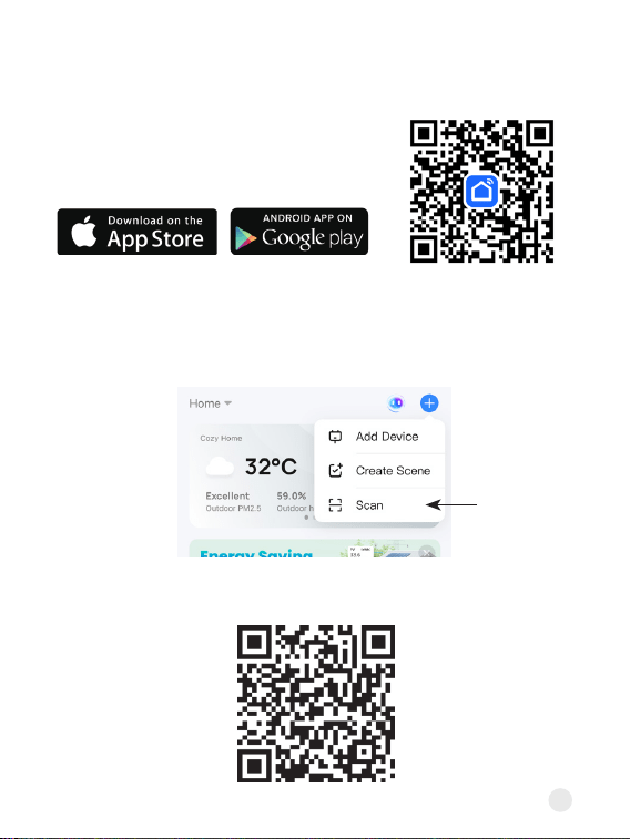
Setup
1. Download the Sma Life app on App Store
or Google Play.
2. Open Smart Life app to create an App account, then click the 'Scan'
button in the upper right corner of the App Home page.
3. Scan the following QR code to congure the network.
34
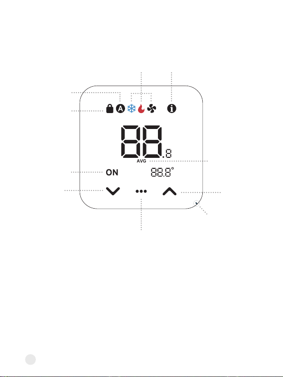
Using your thermostat
Fuher description
Settings Page Toggle
Up button
Air vent for temp
measurement
Avg. temp icon
Info icon
Lock icon
Auto mode
Cool / Heat / Fan Settings icon
Running
status
Down
button
• Lock icon
Appears when using the App to disable specic functions
• Running status
Display ON only for the active setting (cooling, heating, or fan) on its
respective settings page
35
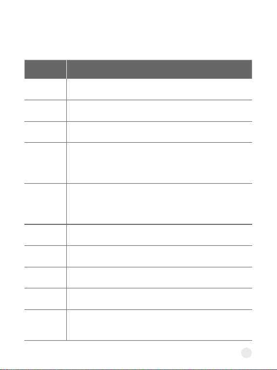
• Info icon
The status gives the following information:
Status What it means
Green LED blinking Wait for Wi-Fi pairing
Red LED solid on
Device is connected to the router, but
failed to connect to the cloud.
Red LED blinking
Wi-Fi has been congured, but failed to
connect to the router.
Orange LED solid on
Using Aux. heat or ALT. Heat or
Emergency Heat
Orange LED blinking System delay to prevent wear.
• Avg. temp icon
Displayed when more than one sensor is involved in the temperature
calculation
• Settings Page Toggle (Center button)
This button can do the following:
1. Tap once to switch between settings pages (Cool/Heat/Fan Settings)
2. Change the HVAC mode: Press and hold it for 3 seconds
3. Clear Wi-Fi: Press and hold it. After 10 seconds, a countdown will sta.
Continue to hold the button until the countdown reaches 0.
• Facto Reset
Press and hold the Up and Down buttons for 10 seconds until the screen
displays ‘RST’. Hold the Center button until the countdown nishes.
36
Adding your Sensor
(Optional)
Link Alexa and Google Assistant
1. Open the Sma Life app and go to Settings.
2. Find the Sensor option and tap on it.
3. Tap the + icon in the top right corner.
4. Follow the on-screen instructions to add the sensor.
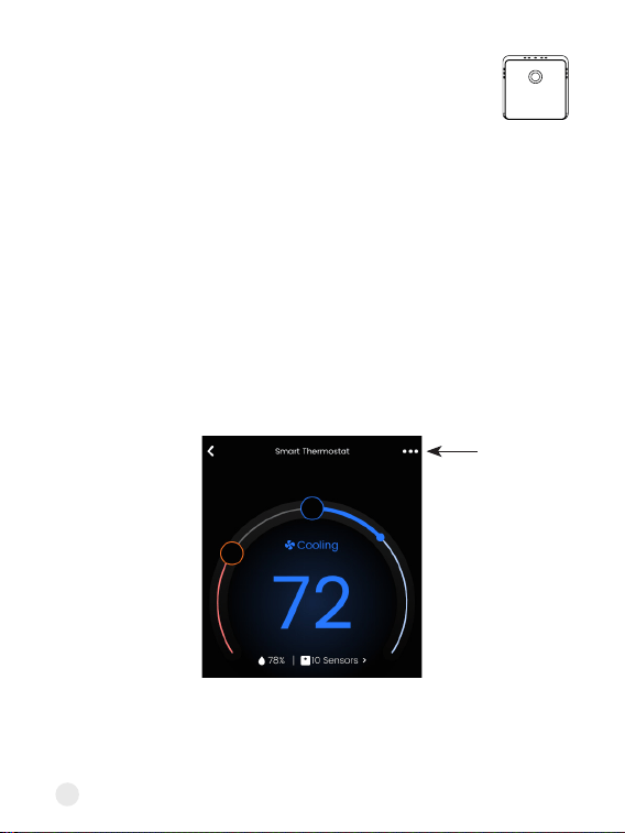
1. Open the Sma Life and tap the three dots in the top right corner of the
home screen.
2. Tap the Third-pay Control option.
3. Follow the steps to link Alexa and Google.