

OPERATOR’S MANUAL
12 inch Max Reach Miter Saw
R4231
Your saw has been engineered and manufactured to our high standard for dependability, ease of operation, and operator
safety. When properly cared for, it will give you years of rugged, trouble-free performance.
WARNING:
To reduce the risk of injury, the user must read and understand the operator’s manual before using this product.
SAVE THIS MANUAL FOR FUTURE REFERENCE

2
TABLE OF CONTENTS
NOTE: The manual cover illustrates the current production model. All other illustrations contained in the manual are representative
only and may not be exact depictions of the actual labeling or accessories included. They are intended for illustrative purposes only.
FEATURES ......................................................................2
PRODUCT SPECIFICATIONS ...........................................2
KNOW YOUR COMPOUND MITER SAW ........................... 5
IMPORTANT SAFETY INSTRUCTIONS ......................6
SAFETY LOGOS ..............................................................6
GENERAL POWER TOOL SAFETY WARNINGS .........7
SAFETY INSTRUCTIONS FOR MITER SAWS............8
PROPOSITION 65 WARNING .....................................9
POWER CONNECTIONS ............................................. 10
DOUBLE INSULATION .................................................. 10
ELECTRICAL CONNECTION .......................................... 10
POLARIZED PLUGS ...................................................... 10
EXTENSION CORDS .................................................... 10
UNPACKING ................................................................. 11
REMOVING CONTENTS FROM PACKING ........................ 11
PACKAGED CONTENTS LIST ........................................ 11
ASSEMBLY .................................................................... 12
TOOLS NEEDED .......................................................... 12
WORK CLAMP ............................................................. 13
DUST BAG .................................................................. 13
INSTALL/REMOVE/REPLACE THE BLADE ....................... 14
ADJUSTMENTS ............................................................ 15
ALIGN THE BLADE TO TABLE ....................................... 15
ALIGN THE BLADE TO FENCE ...................................... 16
DEPTH STOP ADJUSTMENT ......................................... 17
FENCE EXTENSION ..................................................... 17
BEVEL LOCK TENSION ADJUSTMENT .......................... 17
SLIDE RESISTANCE ..................................................... 18
MITER LOCK ADJUSTMENT .......................................... 18
THROAT PLATE ........................................................... 19
MOUNTING AND TRANSPORTATION ..................... 20
PREPARATIONS FOR TRANSPORTATION ....................... 20
MOUNTING SAW TO STABLE SURFACE ......................... 21
OPERATION ................................................................. 22
CUTTING WARPED MATERIAL ...................................... 23
CLAMPING WIDE WORKPIECES ................................... 23
SUPPORTING LONG WORKPIECES ............................... 24
POWER SWITCH LOCK ................................................ 24
NON-SLIDING CUTS .................................................... 25
FOR MITER CUTS ........................................................ 25
FOR BEVEL CUTS ........................................................ 26
FOR COMPOUND MITER CUTS ..................................... 27
SLIDE CUTS ................................................................ 28
TIPS FOR CUTTING CROWN MOLDING ......................... 29
AUXILIARY FENCE ....................................................... 30
EXPAND WORKTABLE AREA ......................................... 31
MAINTENANCE ............................................................ 32
KEEP MACHINE CLEAN ................................................ 32
GENERAL MAINTENANCE............................................. 32
BRUSH REPLACEMENT ................................................ 32
LUBRICATION ............................................................. 32
TROUBLE SHOOTING ................................................. 33
FAILURE TO START ..................................................... 33
ACCESSORIES ............................................................. 33
PARTS, SERVICES OR WARRANTY ASSISTANCE . 34
FEATURES
PRODUCT SPECIFICATIONS
Cutting Capacity
(Maximum nominal
lumber sizes)
0° Miter/0° Bevel: 4 inch x 10 inch
(2 x 12 inch Extended Capacity)
45° Miter/ 0° Bevel: 4 inch x 6 inch
0° Miter/45° Bevel: 2 inch x 10 inch
(Left & Right 45° Bevel:1 inch x 10
inch)
45° Miter/45° Bevel: 2 inch x 6 inch
(Left & Right 45°Bevel: 1 inch x 6
inch)
Baseboard (Vertical) 6 inch
Crown (Vertically Nested) 7.5 inch
Net Weight 57 lbs
Input 120 V~, 60hz, 15 Amps
Blade Arbor Hole 1 inch
Blade Diameter 12 inch
No Load Speed 4,000 r/min (RPM)
Blade Max Speed Rating 5,500 r/min (RPM)
Number of Teeth 40
Blade Thickness 0.079 inch (2mm)
Blade Kerf 0.11 inch (2.8mm)
BLADE DESCRIPTIONS
APPLICATION DIAMETER TEETH
Construction Saw Blades
(thin kerf with anti-stick rim)
General Purpose 12 inch (305mm) 40
Fine Crosscuts 12 inch (305mm) 60
Woodworking Saw Blades
(provide smooth, clean cuts)
Fine crosscuts 12 inch (305mm) 80
NOTE: ONLY use blades that are marked for speeds of
4,000 r/min (RPM) or higher. NEVER use a smaller diameter
blade. It will not be guarded properly. Use crosscut blades
only. DO NOT use blades designed for ripping, combination
blades or blades with hook angles in excess of 7°.
3
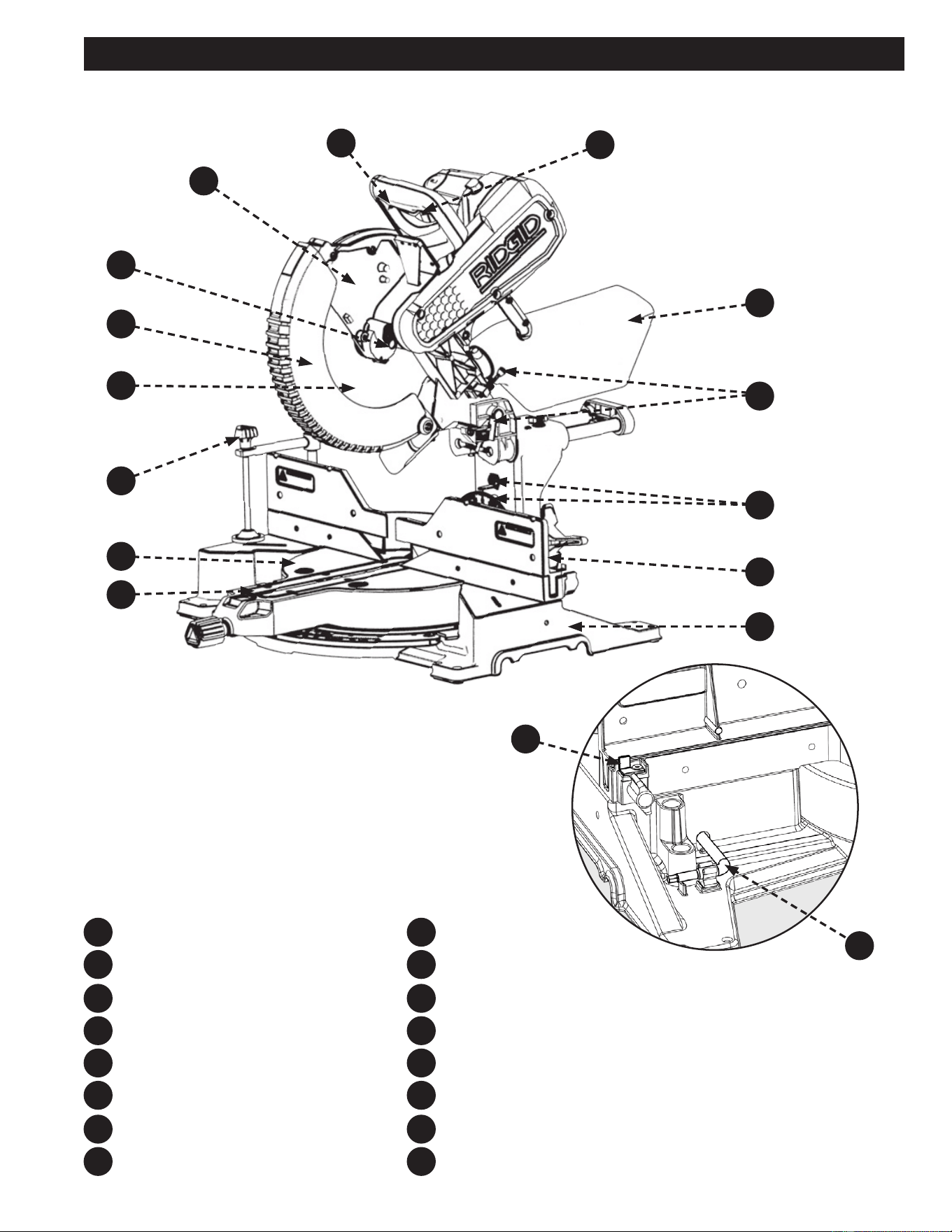
FEATURES
Figure 1
On/O Switch and Lockout Hole
Safety Switch
Dust Bag
Depth Stop Screw/Depth Stop Plate
Bevel Scale and Indicator
Sliding Fence
Base
Throat Plate
F10
F10
F16
F11
F11
F12
F12
F13
F13
F14
F14
F15
F5
F5
F6
F6
F7
F7
F8
F8
F1
F1
F2
F2
F3
F3
F4
F4
F9
F9
F16
F15
Work Table
Work Clamp
Blade
Lower Guard
Spindle Lock
Upper Guard
Back Fence Support
T30 Torx/Blade Wrench
4
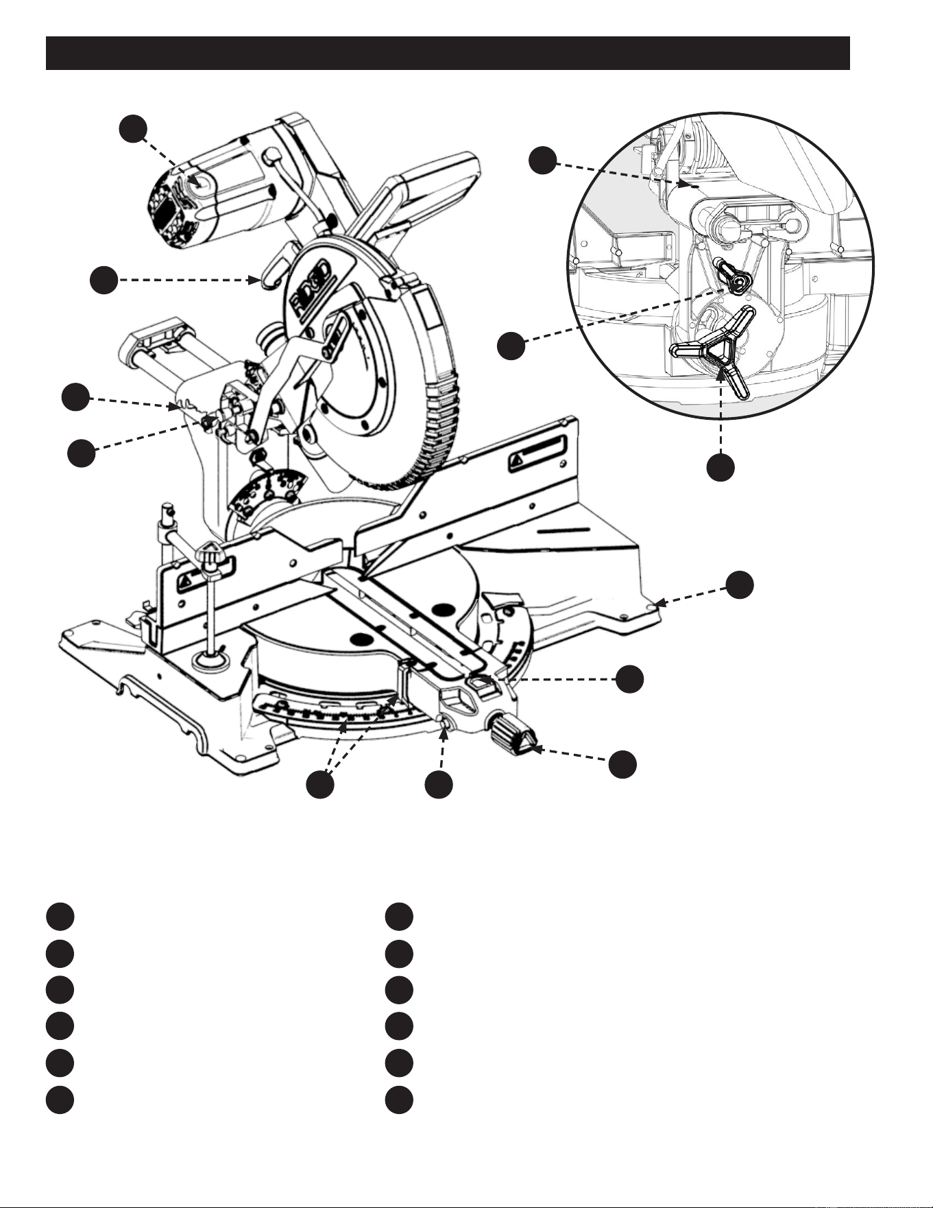
Motor End Cap
Carrying Handle
Slide Lock Lever
Saw Head Lock Pin
Miter Scale and Indicator
Miter Detent Override Button
FEATURES
Figure 2
F24
F18
F25
F19
F26
F20
F27F21
F28F22
F23F17
Miter Lock Knob
Miter Detent Lock/Unlock Button
Mounting Holes (4)
Bevel Lock/Unlock Handle
Bevel Detent Latch
Slide Resistance Adjustment
F24
F18
F17
F19
F20
F26
F27
F28
F25
F22
F23
F21

5
FEATURES
KNOW YOUR COMPOUND MITER SAW
1. On/Off Switch and Lockout Hole: This saw
is activated by an easy to use, hand operated,
power switch. When not in use the saw should be
disconnected from the power supply and locked using a
padlock inserted through the lockout hole located on the
power switch.
2. Safety Switch: This switch helps prevent accidental
start, must be engaged along with power switch to
operate machine.
3. Dust Bag: The dust bag collects and contains the saw
dust during the cutting operations.
4. Depth Stop Screw/Depth Stop Plate: The depth
stop plate can be used to make a non-through cut. The
depth stop screw allows the depth of cut to be adjusted.
5. Bevel Scale and Indicator: These indicate the
current blade bevel position and are adjustable; This
allows for ne calibration of the blade alignment.
6. Sliding Fence: The fence supports the workpiece when
making all cuts. The extension is adjustable.
7. Base: Supports the tool and features mounting holes.
8. Throat Plate (Kerf Plate): The throat plate supports
the workpiece from underneath, on both sides of the
blade, to minimize workpiece tear out
9. Work Table: The die-cast aluminum work table
provides a level and sturdy work surface.
10. Work Clamp: The vertical work clamp helps to position
and secure the workpiece to the work table. This
provides for safer operation and more accurate cuts.
11. Blade: A 12 inch blade is included with the compound
miter saw.
12. Lower Guard: The lower blade guard is made of
shock-resistant, see-through plastic that provides
protection from the blade.
13. Spindle Lock: Engage the spindle lock when changing
the blade in order to hold the blade into position while
you loosen the blade bolt.
14. Upper Guard: Cast aluminum protects user from blade.
15. Back Fence Support: These provide workpiece
support and additional cut capacity when the sliding
fence is removed.
16. T30 Torx/Blade Wrench: This wrench should be used
when removing, installing, or changing the blade.
17. Motor End Cap: This provides access to your saw’s
motor’s Brush Caps/carbon brushes, in the event they
need to be inspected or replaced.
18. Carrying Handle: Use this to transport your saw.
Make sure the Slide and Head lock are engaged before
transporting.
19. Slide Lock Lever: This allows the saw head to be
locked into the fully retracted position.
20. Saw Head Lock Pin: This allows the saw head to be
locked into the full down position, for transportation.
21. Miter Scale and Indicator: These indicate the current
blade miter position and are adjustable; This allows for
ne calibration of the blade alignment.
22. Miter Detent Override Button: This button holds the
miter detent into the unlocked position which allows
free movement of work table arm without holding the
miter detent lock/unlock button.
23. Miter Lock Knob: This knob locks the blade miter
angle securely into place. Always lock before making
any cuts.
24. Miter Detent Lock/Unlock Button: This button
allows you to release the miter arm from the positive
stops and freely rotate the miter arm.
25. Mounting Holes (x4): Enables you to securely mount
the tool to a stable surface.
26. Bevel Lock/Unlock Handle: This handle locks the
blade bevel angle securely into place. Always lock
before making any cuts.
27. Bevel Detent Latch: This latch engages/disengages
the bevel detent pin which allows the bevel angle to be
locked into one of the detent positions.
28. Slide Resistance Adjustment: This adjusts the
friction for the front to back saw head siding movement.
29. E-Brake (Not Shown): This brake will slow your blade
down quickly when the power switch is disengaged
(release hand from power switch).

6
IMPORTANT SAFETY INSTRUCTIONS
This manual contains information that is important for you to know and understand. This information relates to protecting YOUR
SAFETY and PREVENTING EQUIPMENT PROBLEMS. To help you recognize this information, we use the symbols below. Please read
the manual and pay attention to these sections.
Additional information regarding the safe and proper operation of this tool is available from the following sources:
• Power Tool Institute, 1300 Sumner Avenue, Cleveland, OH 44115-2851 or on-line at www.powertoolinstitute.com
• National Safety Council, 1121 Spring Lake Drive, Itasca, IL 60143-3201
• American National Standards Institute, 25 West 43rd Street, 4 oor, New York, NY 10036 www.ansi.org - ANSI 01.1 Safety
Requirements for Woodworking Machines
• U.S. Department of Labor regulations www.osha.gov
Indicates an imminently hazardous situation which, if not avoided, will result in death or serious injury.
Indicates a potentially hazardous situation which, if not avoided, could result in death or serious injury.
Indicates a potentially hazardous situation which, if not avoided, may result in minor or moderate injury.
Used without the safety alert symbol indicates potentially hazardous situation which, if not avoided, may result in
property damage.
SAFETY LOGOS
CAREFULLY READ AND FOLLOW ALL WARNINGS AND INSTRUCTIONS ON YOUR
PRODUCT AND IN THIS MANUAL. SAVE THIS MANUAL. MAKE SURE ALL USERS ARE FAMILIAR WITH ITS
WARNINGS AND INSTRUCTIONS WHEN USING THE TOOL. Improper operation, maintenance or modication of
tools or equipment could result in serious injury and/or property damage.
Some of the following symbols may be used on the tool. Please study them and learn their meaning. Proper interpretation on these symbols
will allow you to operate the tool better and safer.
SYMBOL NAME DESIGNATION/EXPLANATION
Safety Alert Indicates a potential personal injury hazard.
Read Operator's Manual
To reduce the risk of injury, user must read and understand operator's manual before using this
product.
Eye Protection Always wear eye protection with side shields marked to comply with ANSI Z87.1.
No Hands Symbol Failure to keep your hands away from the blade will result in serious personal injury.
Wet Conditions Alert Do not expose to rain or use in damp locations.
Pinch Warning Always watch for movement paying extra attention to potential areas where pinching could occur.
V Volts Voltage
A Amperes Current
Hz Hertz Frequency (cycles per second)
min Minutes Time
~/AC Alternating Current Type of current
ⁿ
₀
No Load Speed Rotational speed, at no load
.../min Per Minute Revolutions, strokes, surface speed, orbits, etc., per minute
Lbs Pounds Unit of weight
Kg Kilograms Unit of weight
RPM Revolutions Per Minute Speed of rotation of machine
PH:1 Phase 1 This is a 1 phase motor
Double Insulation
Double insulation is a concept in safety in electric power tools, which eliminates the need for the usual three-
wire grounded power cord. All exposed metal parts are isolated from the internal metal motor components with
protecting insulation. Double insulated tools do not need to be grounded.

7
GENERAL POWER TOOL SAFETY WARNINGS
The term “power tool” in the warnings refers to your mains-operated (corded) power tool or BATTERY-operated (cordless) power
tool.
1. Work area safety
a. Keep work area clean and well lit. Cluttered or dark areas invite accidents.
b. Do not operate power tools in explosive atmospheres, such as in the presence of ammable liquids,
gases or dust. Power tools create sparks which may ignite the dust or fumes.
c. Keep children and bystanders away while operating a power tool. Distractions can cause you to lose control.
2. Electrical safety
a. Power tool plugs must match the outlet. Never modify the plug in any way. Do not use any adapter with
earthed (grounded) power tools. Unmodied plugs and matching outlets will reduce risk of electric shock
b. Avoid body contact with earthed or grounded surfaces, such as pipes, radiators, ranges and
refrigerators. There is an increased risk of electric shock if your body is earthed or grounded.
c. Do not expose power tools to rain or wet conditions. Water entering a power tool will increase the risk of
electric shock.
d. Do not abuse the cord. Never use the cord for carrying, pulling or unplugging the power tool. Keep cord
away from heat oil, sharp edges or moving parts.
Damaged or entangled cords increase the risk of electric
shock.
e. When operating a power tool outdoors, use an extension cord suitable for outdoor use. Use of a cord
suitable for outdoor use reduces the risk of electric shock.
f. If operating a power tool in a damp location is unavoidable, use a ground fault circuit interrupter (GFCI)
protected supply. Use of an GFCI reduces the risk of electric shock.
3. Personal safety
a. Stay alert, watch what you are doing and use common sense when operating a power tool. Do not use
a power tool while you are tired or under the inuence of drugs, alcohol or medication. A moment of
inattention while operating power tools may result in serious personal injury.
b. Use personal protective equipment. Always wear eye protection. Protective equipment such as dust mask,
non-skid safety shoes, hard hat, or hearing protection used for appropriate conditions will reduce personal injuries.
c. Prevent unintentional starting. Ensure the switch is in the o-position before connection to power
source, picking up, or carrying the tool. Carrying power tools with your nger on the switch or energising power
tools that have the switch on invites accidents.
d. Remove any adjusting key or wrench before turning the power tool on. A wrench or a key left attached to a
rotating part of the power tool may result in personal injury.
e. Do not overreach. Keep proper footing and balance at all times. This enables better control of the power tool
in unexpected situations.
f. Dress properly. Do not wear loose clothing or jewelery. Keep your hair, clothing and gloves away from
moving parts. Loose clothes, jewelery or long hair can be caught in moving parts.
g. If devices are provided for the connection of dust extraction and collection facilities, ensure these are
connected and properly used. Use of dust collection can reduce dust-related hazards.
h. Do not let familiarity gained from frequent use of tools allow you to become complacent and ignore tool
safety principles. A careless action can cause severe injury within a fraction of a second.
4. Power tool use and care
a. Do not force the power tool. Use the correct power tool for you application. The correct power tool will do
the job better and safer at the rate for which it was designed.
b. Do not use the power tool if the switch does not turn it on and o. Any power tool that cannot be controlled
with the switch is dangerous and must be repaired.
c. Disconnect the plug from the power source before making any adjustments, changing accessories, or
storing power tools. Such preventive safety measures reduce the risk of starting the power tool accidentally.
Read all safety warnings, instructions, illustrations and specications provided with this power tool.
Failure to follow all instructions listed below may result in electric shock, re and/or serious injury.
Save all warnings and instructions for future reference.

8
SAFETY INSTRUCTIONS FOR MITER SAWS
d. Store idle power tools out of the reach of children and do not allow persons unfamiliar with the power
tool or these instructions to operate the power tool. Power tools are dangerous in the hands of untrained users.
e. Maintain power tools and accessories. Check for misalignment or binding of moving parts, breakage of
parts and any other condition that may aect the power tool’s operation. If damaged, have the power
tool repaired before use. Many accidents are caused by poorly maintained power tools.
f. Keep cutting tools sharp and clean. Properly maintained cutting tools with sharp cutting edges are less likely to
bind and are easier to control.
g. Use the power tool, accessories and tools bits etc. in accordance with these instructions, taking into
account the working conditions and the work to be performed.
Use of the power tool for operations dierent
from those intended could result in a hazardous situation.
h. Keep Handles and grasping surfaces dry, clean and free from oil and grease. Slippery handles and grasping
surfaces do not allow for safe handling and control of the tool in unexpected situations.
5. Service
a. Have your power tool serviced by a qualied repair person using only identical replacement parts. This
will ensure that the safety of the power tool is maintained.
1.
a. Miter saws are intended to cut wood or wood-like products, they cannot be used with abrasive cut-o
wheels for cutting ferrous material such as bars, rods, studs, etc
. Abrasive dust causes moving parts such as
the lower guard to jam. Sparks from abrasive cutting will burn the lower guard, the kerf insert and other plastic parts.
b. Use clamps to support the workpiece whenever possible. If supporting the workplace by hand, you must
always keep your hand at least 100mm from either side of the saw blade. Do not use this saw to cut
pieces that are too small to be securely clamped or held by hand. If your hand is placed too close to the saw
blade, there is an increased risk of injury from blade contact.
c. The workpiece must be stationary and clamped or held against both the fence and the table. Do not feed
the workpiece into the blade or cut “freehand” in any way. Unrestrained or moving workpieces could be thrown
at high speeds, causing injury.
d. Push the saw through the workpiece. Do not pull the saw through the workpiece. To make a cut, raise
the saw head and pull it out over the workpiece without cutting, start the motor, press the saw head
down and push the saw through the workpiece. Cutting on the pull stroke is likely to cause the saw blade to
climb on top of the workpiece and violently throw the blade assembly towards the operator.
e. Never cross your hand over the intended line of cutting either in front or behind the saw blade.
Supporting the workpiece “cross handed” i.e. holding the workpiece to the right of the saw blade with your left hand or
vice versa is very dangerous.
f. Do not reach behind the fence with either hand closer than 100mm from either side of the saw blade, to
remove wood scraps, or for any other reason while the blade is spinning. The proximity of the spinning saw
blade to your hand may not be obvious and you may be seriously injured.
g. Inspect your workpiece before cutting. If the workpiece is bowed or warped, clamp it with the outside
bowed face toward the fence. Always make certain that there is no gap between the workpiece, fence
and table along the line of the cut. Bent or warped workpieces can twist or shift and may cause binding on the
spinning saw blade while cutting. There should be no nails or foreign objects in the workpiece.
h. Do not use the saw until the table is clear of all tools, wood scraps, etc., except for the workpiece. Small
debris or loose pieces of wood or other objects that contact the revolving blade can be thrown with high speed.
i. Cut only one workpiece at a time. Stacked multiple workpieces cannot be adequately clamped or braced and may
bind on the blade or shift during cutting.
j. Ensure the miter saw is mounted or placed on a level, rm work surface before use. A level and rm work
surface reduces the risk of the miter saw becoming unstable.
k. Plan your work. Every time you change the bevel or miter angle setting, make sure the adjustable fence
is set correctly to support the workpiece and will not interfere with the blade or the guarding system.
Without turning the tool “ON” and with no workpiece on the table, move the saw blade through a complete simulated
cut to assure there will be no interference or danger of cutting the fence.
GENERAL POWER TOOL SAFETY WARNINGS

9
SAFETY INSTRUCTIONS FOR MITER SAWS
PROPOSITION 65 WARNING:
l. Provide adequate support such as table extensions, saw horses, etc. for a workpiece that is wider or
longer than the table top
. Workpieces longer or wider than the miter saw table can tilt if not securely supported. If the cut-o
piece or workpiece tips, it can lift the lower guard or be thrown by the spinning blade.
m. Do not use another person as a substitute for a table extension or as additional support. Unstable support
for the workpiece can cause the blade to bind or the workpiece to shift during the cutting operation pulling you and
the helper into the spinning blade.
n. The cut-o piece must not be jammed or pressed by any means against the spinning saw blade. If
conned, i.e. using length stops, the cut-o piece could get wedged between the blade and thrown violently.
o. Always use a clamp or a xture designed to properly support round material such as rods or tubing. Rods
have a tendency to roll while being cut, causing the blade to “bite” and pull the work with your hand into the blade.
p. Let the blade reach full speed before contacting the workpiece. This will reduce the risk of the workpiece
being thrown.
q. If the workpiece or blade becomes jammed, turn the miter saw o. Wait for all moving parts to stop
and disconnect the plug from the power source and/or remove the battery pack. Then work to free the
jammed material. Continued sawing with a jammed workpiece could cause loss of control or damage to the miter
saw.
r. After nishing the cut, release switch, hold the saw down and wait for the blade to stop before removing
the cut-o piece. Reaching with your hand near the coasting blade is dangerous.
s. Hold the handle rmly when making an incomplete cut or when releasing the switch before the saw
head is completely in the position. The braking action of the saw may cause the saw to be suddenly pulled
downward, causing a risk of injury.
t. Saw Head lock pin is for storage and transport only. This saw should never be locked in the down position while
making cuts.
u. Do not operate saw without guards in place.
SAVE THESE INSTRUCTIONS.
Refer to them often and use them to instruct others.
If tool is loaned to someone, also loan them these instructions.
Dust created by power sanding, sawing, grinding, drilling, and other construction activities may contain chemicals
known to the state of California to cause cancer, birth defects or other reproductive harm. Some examples are:
• Lead from lead-based paints
• Crystalline silica from bricks and cement and other masonry products
• Asbestos dust
• Arsenic and chromium from chemically-treated lumber
Your risk from these exposures varies depending on how often you do this type of work. To reduce your exposure to these chemicals:
work in a well-ventilated area and work with approved safety equipment, such as dust masks that are specically designed to lter
out microscopic particles.
Avoid prolonged contact with dust from power sanding, sawing, grinding, drilling, and other construction activities.
Wear protective clothing and wash exposed areas with soap and water.

10
POWER CONNECTIONS
This machine is double insulated. Double insulation is a concept in safety in electric power tools, which eliminates the need for
the usual three-wire grounded power cord. All exposed metal parts are isolated from the internal metal motor components with
protecting insulation. Double insulated tools do not need to be grounded.
NOTE: Servicing of a tool with double insulation requires extreme care and knowledge of the system and should be performed by a
qualified service technician. For service, we suggest you return the tool to the nearest authorized service center for repair. ALWAYS
use identical replacement parts when servicing.
Your machine is wired for 120 volts, 60 HZ alternating current. Before connecting the machine to the power source, make sure the
switch is in the “OFF” position.
DOUBLE INSULATION
DO NOT EXPOSE THE MACHINE TO RAIN OR OPERATE THE MACHINE IN DAMP LOCATIONS.
The double insulated system is designed to protect the user from shock resulting from a break in the tool’s
internal insulation. However, it is important to observe normal safety precautions to avoid electrical shock.
This tool has a precision-built electric motor. It should be connected to a POWER SUPPLY THAT IS 120 VOLTS, 60 HZ, AC ONLY
(NORMAL HOUSEHOLD CURRENT in the U.S. and Canada). DO NOT operate this tool on direct current (DC). A substantial voltage
drop will cause a loss of power and the motor will overheat. If the tool does not operate when plugged into an outlet, double-check
the power supply.
To reduce the risk of electric shock, this equipment has a polarized plug (one blade is wider than the other). This plug will fit in a
polarized outlet only one way. If the plug does not fully fit in the outlet reverse the plug. If it still does not fit, contact a qualified
electrician to install the proper outlet. DO NOT change the plug in any way.
When using a power tool at a considerable distance from a power source, be sure to use an extension cord that has the capacity to
handle the current the tool will draw. An undersized cord will cause a drop in line voltage, resulting in overheating and loss of power.
Use the chart to determine the minimum wire size required in an extension cord. ONLY round jacketed cords listed by Underwriter’s
Laboratories (UL) should be used.
NOTE: Before using any extension cord, inspect it for loose
or exposed wires and cut or worn insulation.
** Ampere rating (on total data label)
12A- 16A
Cord Length Wire Size
25' 14 AWG
50' 12 AWG
** Used on 12 gauge - 20 amp circuit
NOTE: AWG = American Wire Gauge
ELECTRICAL CONNECTION
POLARIZED PLUGS
EXTENSION CORDS
KEEP the extension cord clear of the work
area. Position the cord so that it will not get caught on lumber,
tools or other obstructions while you are working with a power
tool. Failure to do so can result in serious personal injury.
Check extension cords before each use. If damaged replace
immediately. NEVER use tool with a damaged cord, since
touching the damaged area could cause electrical shock
resulting in serious injury.
This saw is equipped with a 15-amp motor for use with a 120-
volt, 60-HZ alternating current.
For voltage, the wiring in a shop is as important as the motor’s
rating. A line intended only for lights may not be able to
properly carry the current needed for a power tool motor; wire
that is heavy enough for a short distance may be too light for
a greater distance; and a line that can support one power tool
may not be able to support two or three. A separate electrical
circuit should be used for your machines. This circuit should
not be less than #12 wire and should be protected with a
20-amp time lag fuse and/or circuit breaker. If an extension
cord is used, use ONLY 3-wire extension cords which have
3-prong grounding-type plugs and matching receptacle which
will accept the machine’s plug. Before connecting the machine
to the power line, make sure the switch is in the “OFF”
position and be sure that the electric current is of the same
characteristics as indicated on the machine. A substantial
voltage drop will cause a loss of power and overheat the
motor. It may also damage the machine.
11
UNPACKING
REMOVING CONTENTS FROM PACKAGING
Check shipping carton and machine for damage before unpacking. Carefully remove packaging materials, parts
and machine from shipping carton. ALWAYS check for and remove protective shipping materials around motor and moving parts.
Lay out all parts on a clean work surface.
• Compare package contents to Component Parts List and Hardware Package List prior to assembly to make sure all items are
present. Carefully inspect parts to make sure no damage occurred during shipping. If any parts are missing, damaged or pre-
assembled, DO NOT assemble. Instead, call RIDGID
® Customer Service at (toll free) 1-888-359-4778.
• If any parts are missing, DO NOT attempt to plug in the power cord and turn the power on. The saw should ONLY be
energized after all parts have been located and correctly assembled.
• This saw is packaged and shipped with saw head secured in the down position. Please see “Preparing Your Saw for Transport”
section of this manual for instructions on how to use the saw head lock pin. Once the saw head is in the upright position,
remove Styrofoam packaging block and discard.
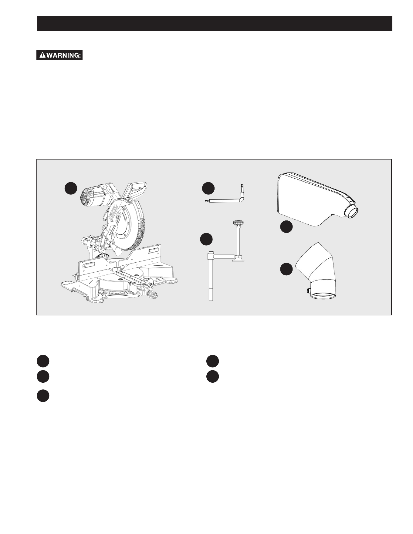
PACKAGED CONTENTS LIST
RIDGID® R4231
T30 Torx/Blade Wrench
(on machine) *see Figure 1 for storage location
Work Clamp
Figure 3
PC1
PC1
PC2
PC2
PC3
PC3
PC4
PC4
PC5
PC5
Dust Bag
2 1/2 inch Dust Port Adapter
12
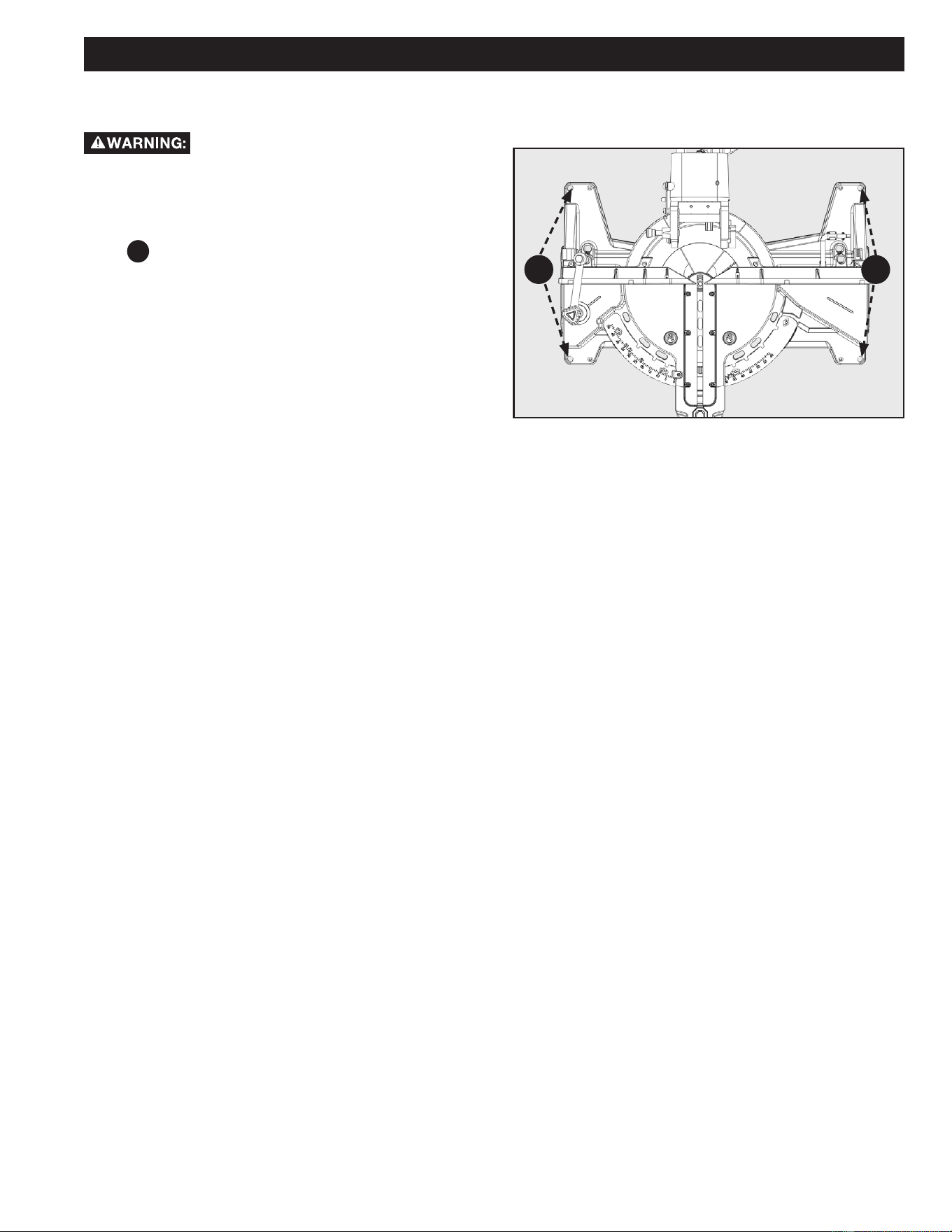
• DO NOT attempt to modify this Tool or create accessories not recommended for use with this Tool. Any such alteration or
modication is misuse and could result in a hazardous condition.
• DO NOT connect to power supply until assembly is complete. Failure to comply could result in accidental starting.
• DO NOT start the Miter Saw without checking for interference between the Blade and the Miter Fence. Damage could result to
the Blade if it strikes the Miter Fence during operation of the Saw.
• ALWAYS re-check for interference when changing miter angle.
• The Saw can tip over if the Saw Head is released suddenly and the Saw is not secured to a work surface. ALWAYS secure this
Saw to a stable work surface before any use.
• If any parts are damaged or missing DO NOT operate this tool until the parts are replaced. Please call RIDGID® Customer
Service at (toll free) 1-888-359-4778.
Figure
4
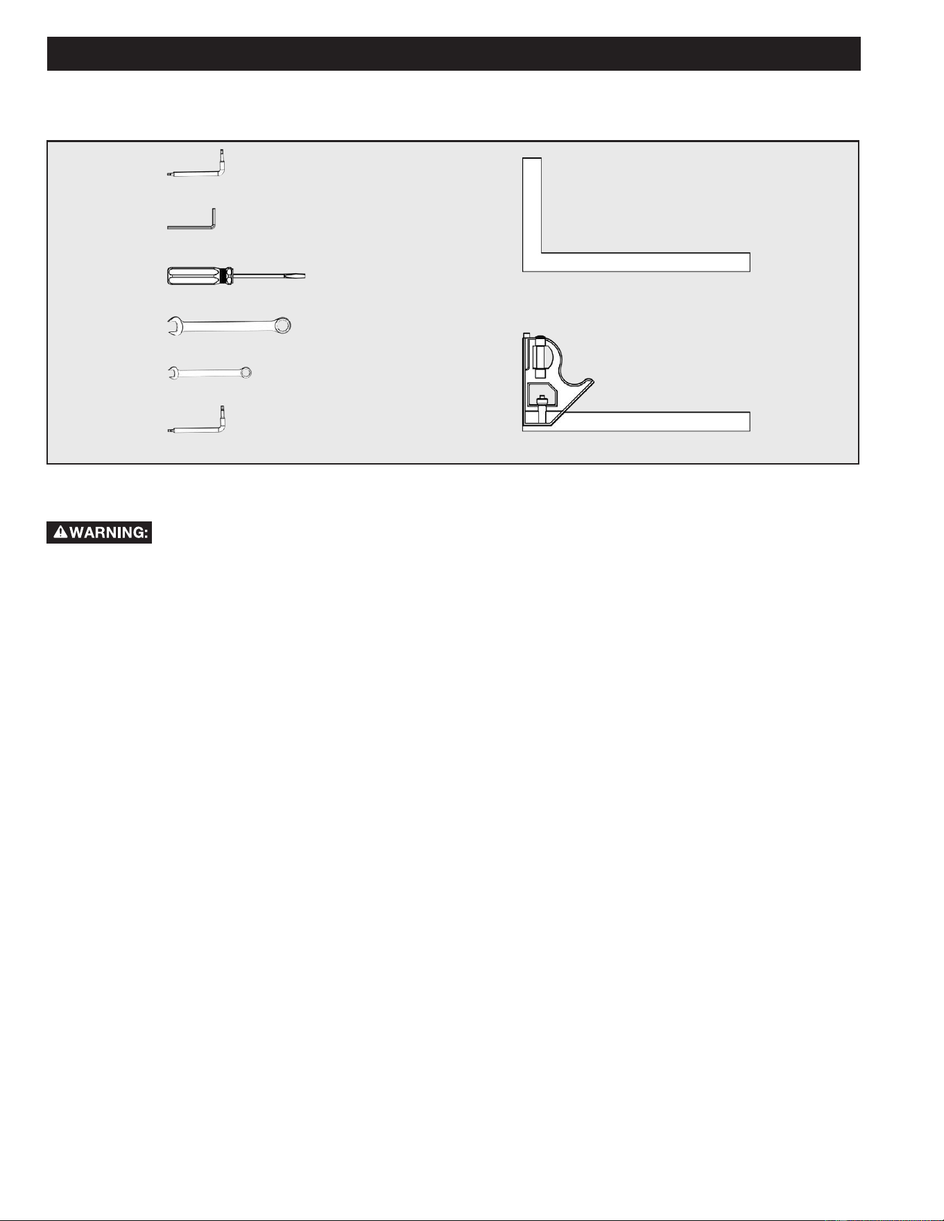
ASSEMBLY
TOOLS NEEDED
T20 Torx Wrench
4mm Hex Wrench
Flat Head Screwdriver
(for the dust port adapter)
17mm Combination Wrench
10mm Combination Wrench
T40 Torx Wrench (L-Shape)
Framing Square
Combination Square
13
ASSEMBLY
WORK CLAMP
See Figure 5
The vertical Work Clamp
F10
secures the workpiece to the
table to provide more stability and keeps the workpiece from
creeping toward the saw blade.
To install the vertical Work Clamp
F10
do the following:
1. Place the Clamp Shaft
A
in either hole
B
on the
Miter Base.
2. Slide the clamp arm so the pad touches the workpiece.
3. Rotate the knob
C
clockwise to secure the workpiece.
To loosen, turn Counter Clock Wise.
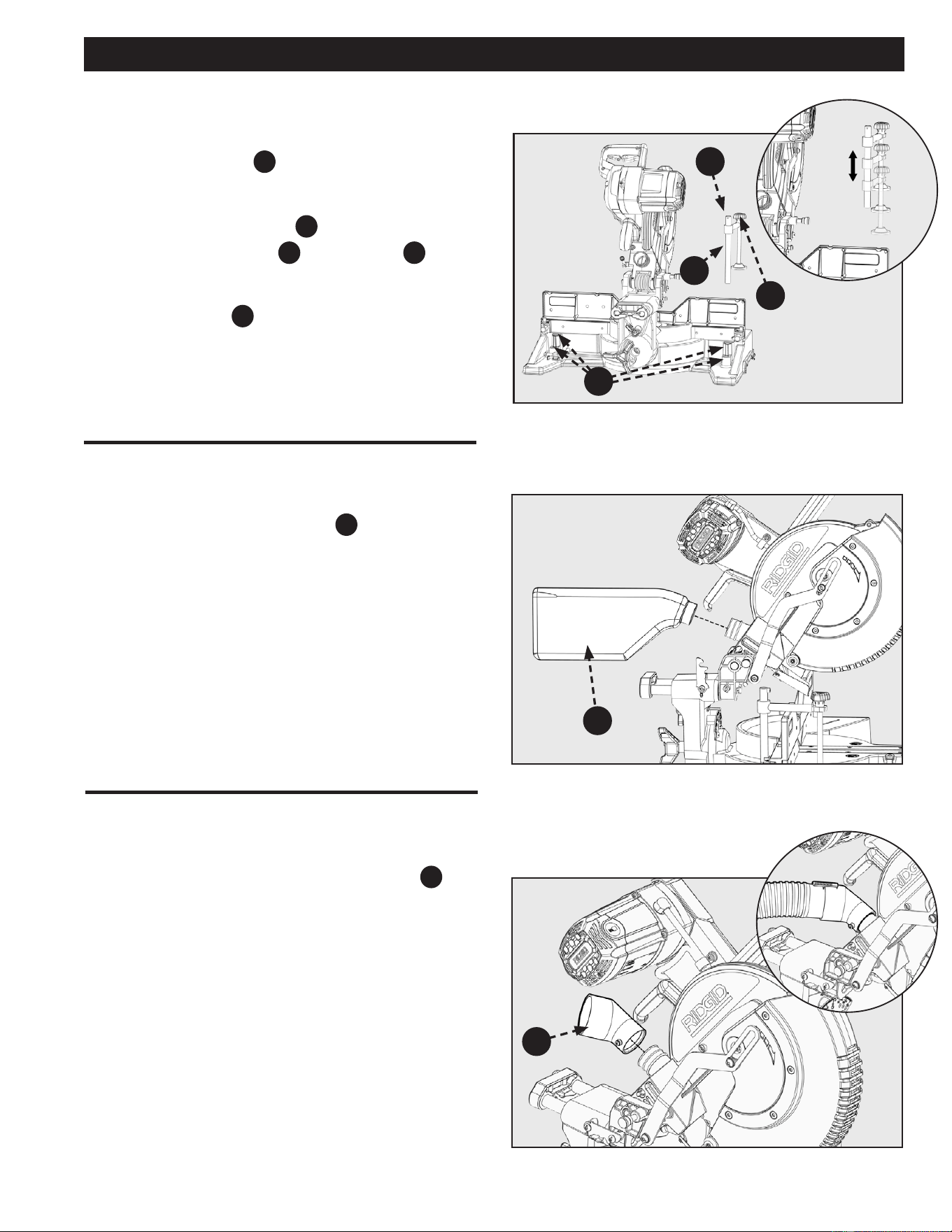
DUST BAG
See Figure 6.
The Tool includes a Dust Collection Bag
PC4
that attaches over
the Exhaust Port on the Upper Blade Guard.
1. Slide the Plastic Collar onto the Dust Exhaust Port on
the back of the Saw Head.
NOTE: To remove the Dust Bag for emptying, simply reverse
the above procedure.
Figure
5
Figure
6
Figure
7
B
PC5
PC4
C
DUST PORT ADAPTER
ATTACHMENT
The tool includes a 2 1/2 inch Dust Port Adapter
PC5
that
attaches over the rear exhaust port on the Upper Blade Guard.
It can be used to connect your miter saw to a standard 2 1/2
inch vacuum or dust collection hose.
1. Install the dust port adapter and tighten the set-screw
using a Phillip’s head screwdriver, as seen in Figure 7.
NOTE: DO NOT over tighten.
A
F10
14
ASSEMBLY
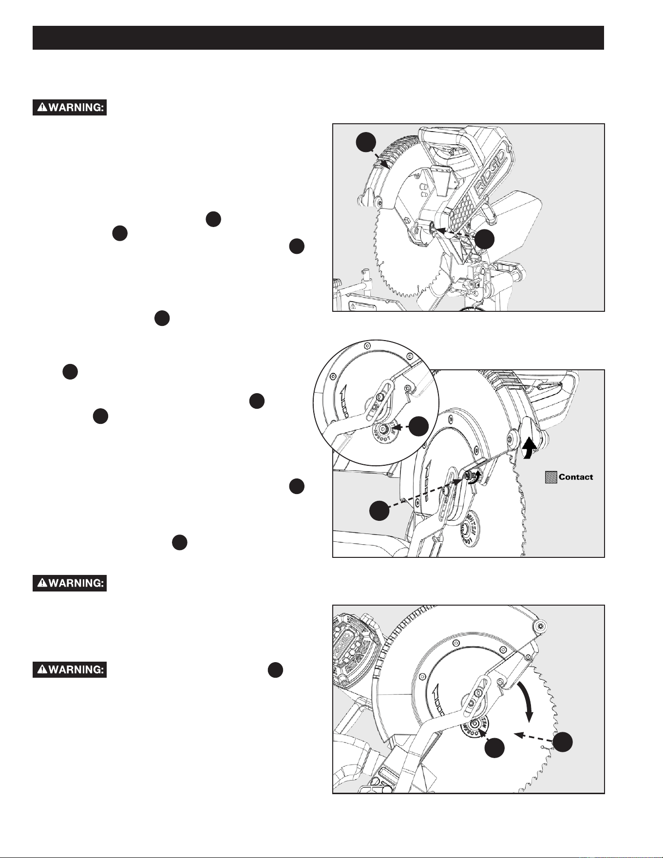
INSTALL/REMOVE BLADE
A 12 inch Blade is the required blade size
for the Saw. Larger blades will come into contact with
the Blade Guards and smaller blades will not be
adequately guarded.
See Figures 8-10.
1. Make sure the Saw is unplugged.
2. Raise the Saw Arm to the full upright position.
3. Rotate the Lower Blade Guard
F12
up to expose the
Blade Bolt
A
. Hold the Lower Blade Guard with the
Right thumb, and press the Spindle Lock Button
F13
with the Right index nger at the same time.
4. If replacing the Blade, carefully rotate the Blade until
the Spindle locks in place.
NOTE: To aid blade change, raise the lower guard and loosen
the blade bolt cover screw
B
a few turns to hold the lower
guard up. Securely tighten the screw back in place when
completing the blade change. See Figure 9.
5. Using the supplied Blade Wrench, remove the Blade Bolt
A
by turning it clockwise.
NOTE: The Blade Bolt has left-hand threads.
6. Remove ONLY the Outer Blade Washer
C
and the
Blade
F11
, leaving the Inner Blade Washer on the
Spindle. See Figure 10.
7. Carefully t Saw Blade inside the Blade Guard and guide
it onto the Spindle, ensuring the Teeth of the Blade are
facing down at the front of the Saw.
8. Align the double “D” Flats on the Blade Washer
C
with the ats on the Spindle and t the Washer onto the
Spindle.
9. Lock the Spindle by depressing the Spindle Lock Button.
Screw on the Blade Bolt
A
, remembering to thread it
counter clockwise. Tighten Blade Bolt securely using the
provided Blade Wrench.
ALWAYS install the Blade with the Blade
Teeth and the arrow on the side of the Blade pointing down at
the front of the Saw. The direction of the Blade rotation is also
stamped with an arrow on the Upper Blade Guard.
10. Raise and lower the Saw Arm to ensure that the Arm
and Blade Guard move freely.
Make sure the Spindle Lock Button
F13
, see
Figure 8 is not engaged before reconnecting Saw to power
source. NEVER engage Spindle Lock button when Blade is
rotating.
NOTE: Some illustrations in this manual indicate only portions
of the Saw. This is done in order to more clearly show key
areas and components of the Saw. NEVER operate the Saw
without all Guards securely in place and in good operating
condition.
Figure 8
Figure 9
Figure 10
F12
F13
A
F11
C
B
15
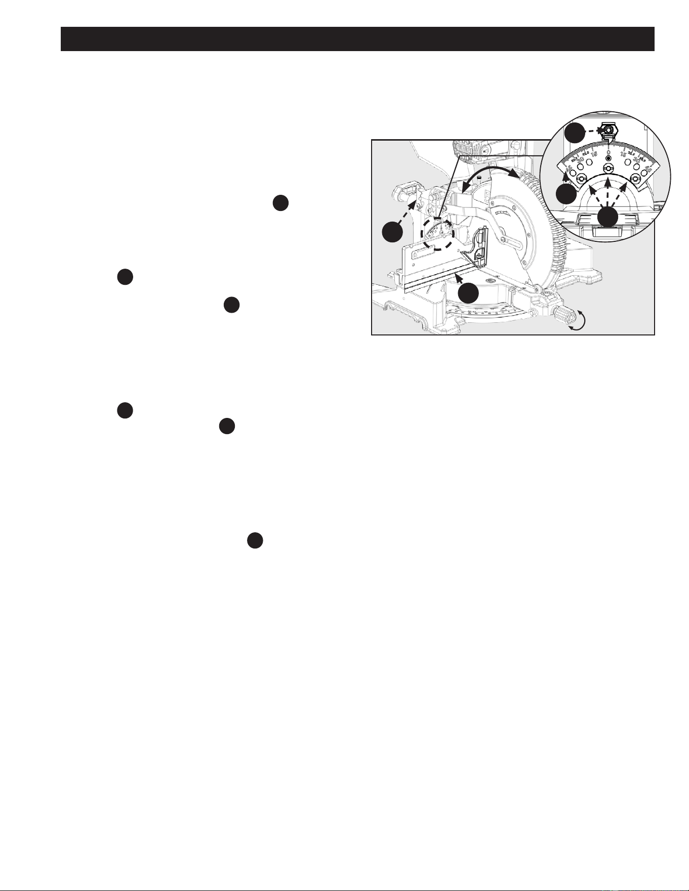
ADJUSTMENTS
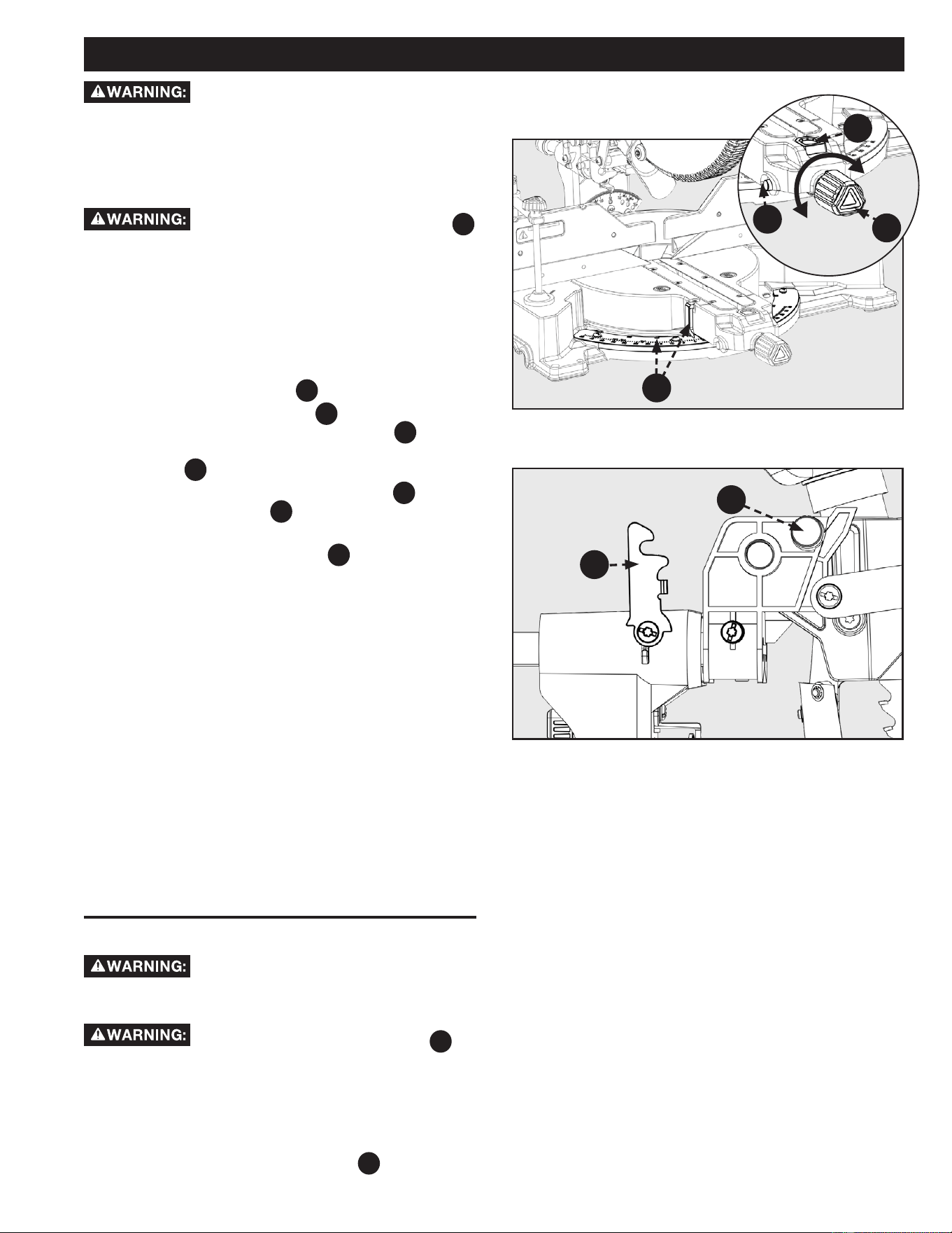
ALIGN THE BLADE TO TABLE
Your saw is calibrated at the factory to cut true. Over time the
saw’s calibration may drift and will need to be re-calibrated.
See Figure 11.
1. Unplug the Saw
2. Lower the saw head all the way down to the transport
position and engage the saw head lock pin to hold it in
place. Push the saw head into the fully retracted
position and engage the slide lock lever
F15
to hold it in
place.
3. Set the miter position to 0° and engage the miter lock
knob so the table will not move.
4. Set the bevel position to 0°. Engage the bevel detent
latch
F27
, located on back, so the detent pin locks into
the bevel detent plate.
5. Place a combination square
A
against the table and
the face of the saw blade .
NOTE: Make sure the square contacts the flat part of the
blade and not the teeth.
6. Rotate the blade by hand and check the blade-to-table
alignment at several points. If the blade face is not ush
with the square you will need to adjust the bevel detent
plate
F5
.
7. Loosen the three screws
B
and adjust the bevel
detent plate position. Set so the table and blade are
ush against the combination square. Make sure the
bevel lock/unlock handle is not locked, so the detent
plate may be adjusted.
8. Re-tighten the three screws and re-check the blade-to-
table alignment.
NOTE: After squaring adjustment has been made, it may be
necessary to loosen the indicator screw
C
, shown in Figure
11, and reset it to zero.
lock
unlock
Figure 11
A
F5
F15
B
C
16
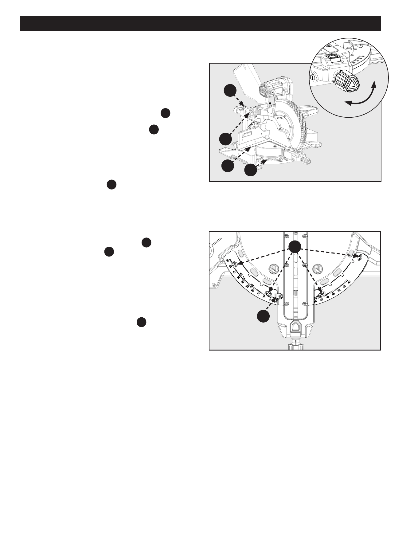
ADJUSTMENTS
ALIGN THE BLADE TO FENCE
Your saw is calibrated at the factory to cut true. Over time the
saw’s calibration may drift and will need to be re-calibrated.
See Figure 12.
1. Unplug the Saw.
2. Lower the saw head all the way down to the transport
position and engage the saw head lock pin
F20
to hold
it in place. Push the saw head into the fully retracted
position and engage the slide lock lever
F19
to hold it in
place.
3. Set the miter position to 0° and allow the miter detent
to lock into position.
4. Set the bevel position to 0°. Tighten the bevel lock
handle to lock bevel angle.
5. Place a framing square
A
against the fence and the
face of the saw blade.
NOTE: Make sure the square contacts the flat part of the
blade and not the teeth.
See Figure 13.
6. If the blade face is not ush with the square you will
need to adjust the miter detent plate
F21
.
7. Loosen the four screws
B
and move the miter table to
adjust the miter detent plate position. Set so the fence
and blade are ush against the combination square.
Make sure the miter lock knob is not locked, so the
miter detent plate may be adjusted.
8. Re-tighten the four screws and re-check the blade-to-
fence alignment.
NOTE: After squaring adjustment have been made, it may be
necessary to loosen the indicator screw
C
, see Figure 13,
and reset it to zero.
LOCK
UNLOCK
Figure 12
Figure 13
B
A
C
F21
F19
F20
17
ADJUSTMENTS
Figure 16
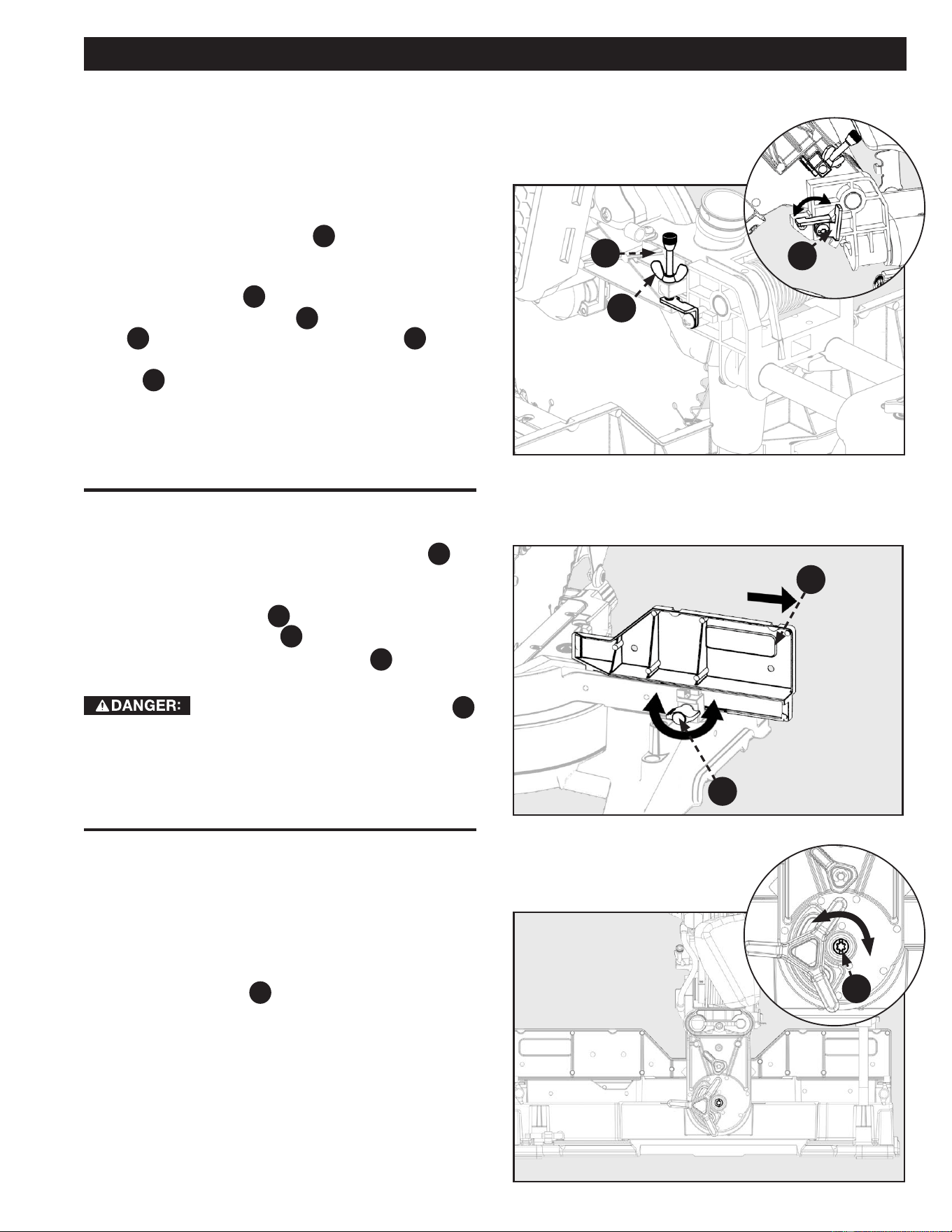
DEPTH STOP ADJUSTMENT
BEVEL LOCK TENSION
ADJUSTMENT
TIGHTEN LOOSEN
Figure 15
FENCE EXTENSION
This miter saw is equipped with an adjustable depth stop for
making non-through cuts.
Refer to Figure 14 and follow these instructions in
order to set the depth stop at a specific cut depth:
1. Rotate the depth stop plate
F4
counterclockwise into
the down position.
2. The cut depth can now be adjusted by turning the
depth stop screw
F4
.
3. Lock the depth stop screw
F4
by turning the Wing-Nut
C
until snug against the depth stop plate
F4
.
NOTE: When finished with non-through cut, rotate depth stop
bracket
F4
clockwise to return to through cut position.
See Figure 16.
Use supplied Torx/blade wrench.
1. Adjust the bevel lock tension by tightening/loosening
the T30 pivot bolt
E
located on the backside of the
saw.
2. Make sure to loosen the bevel lock/unlock handle before
adjusting the T30 bolt. Do not over-tighten.
NOTE: Correct tension is when the cutting head will hold
position when not indexed and unlocked. This only applies at
angles 0 - 20°.
This saw is equipped with an adjustable sliding fence
F6
. To
extend or retract the fence, refer to Figure 15 and follow these
instructions:
1. Loosen the lock knob
D
by rotating counterclockwise
and then slide the fence
F6
into the desired position.
2. Make sure to re-tighten lock knob
D
by rotating
clockwise.
ALWAYS check to make sure lock knob
D
is tightened before making a cut. Failure to do so may result in
injury.
F4
C
F4
F6
D
Figure 14
E
18
ADJUSTMENTS
Figure 17
Figure 18
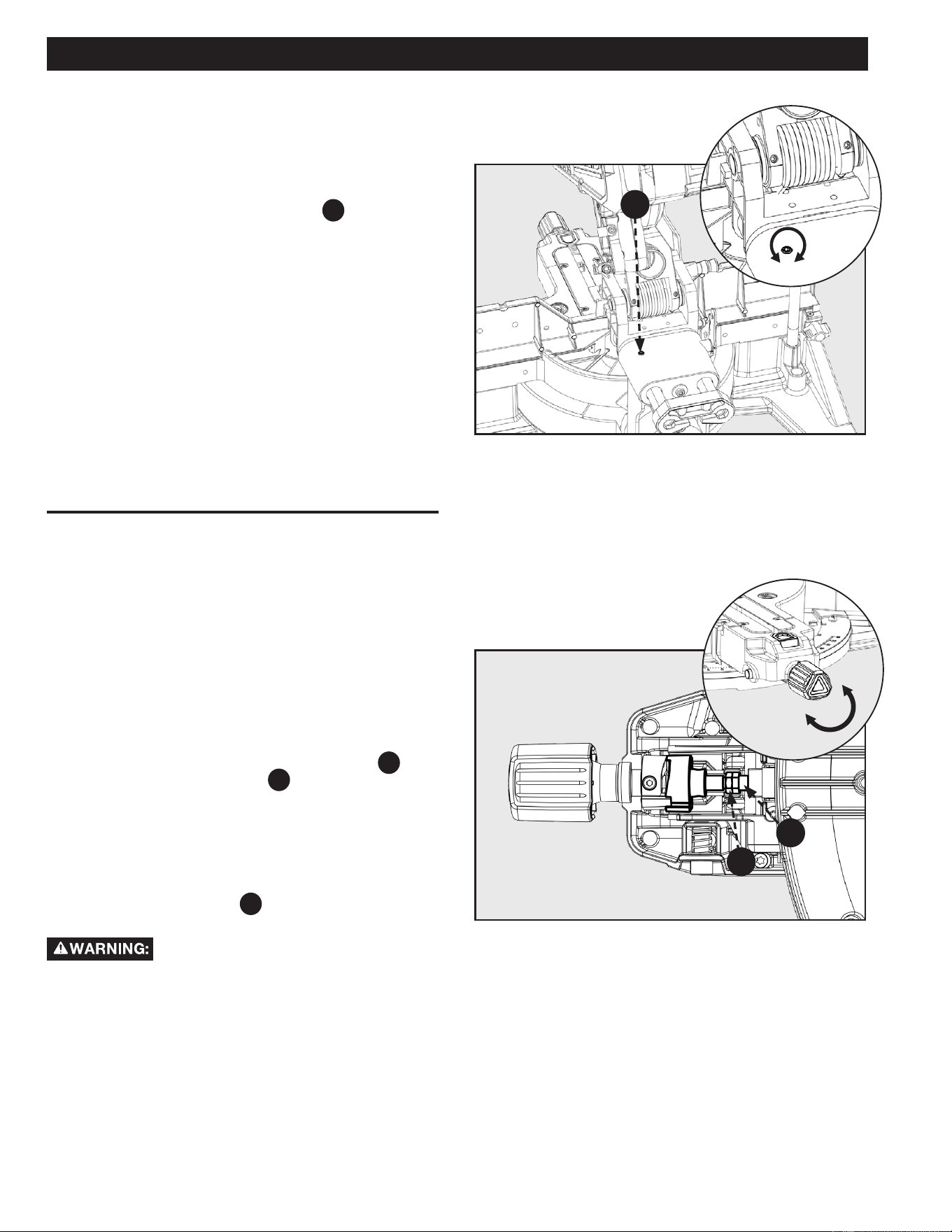
SLIDE RESISTANCE ADJUSTMENT
MITER LOCK ADJUSTMENT
See Figure 17.
The slide resistance (friction) on your saw is adjustable.
1. Use the supplied 4mm Hex wrench. Locate the friction
adjustment screw on the saw slide
F28
. Turn right to
tighten the sliding friction. Turn left to loosen the sliding
friction.
See Figure 18.
If your saw’s miter lock does not lock securely, you need to
tighten the miter lock adjustment. This adjustment is located
on the underside of the miter saw arm.
To make adjustments;
1. Unlock the miter lock knob. Use a 10mm open ended
wrench to loosen (counterclockwise) lock nut
B
while
holding the adjustment rod
C
in place using another
10mm open end wrench.
2. Turn the adjustment rod in order to tighten/loosen the
miter lock. Lock/Unlock the miter lock knob to check the
miter lock adjustment.
3. Once you have set your miter lock adjustment
re-tighten the lock nut
B
to prevent this adjustment
from loosening over time.
TIGHTEN
LOOSEN
ALWAYS check to make sure the miter lock
is locked tightly before using your saw. Failure to follow these
instructions could result in serious personal injury due to the
miter lock slipping during use of the saw.
LOCK
UNLOCK
C
F28
B
19
ADJUSTMENTS
Figure 19
A
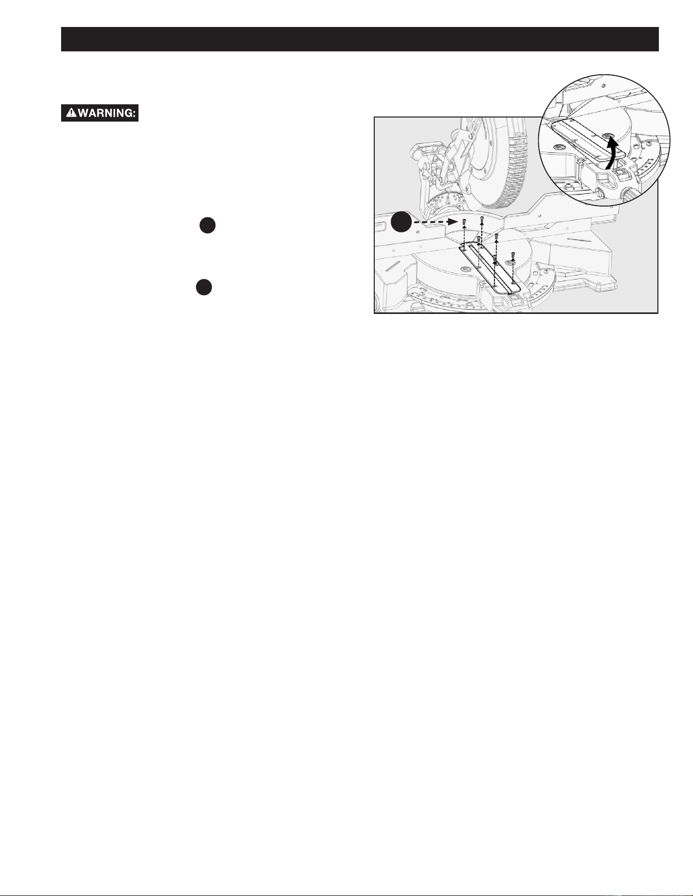
THROAT PLATE
See Figures 19.
ONLY use RIDGID® authorized service parts.
Using non-authorized parts can results in damage to your
machine and serious personal injury.
In the event that your throat plate needs to be replaced for
any reason, follow these instruction.
1. Loosen the fence lock knobs. Slide both fences away
from center.
2. Remove the six screws
A
which hold the throat plate.
Lift the throat plate o the work table.
3. Replace the throat plate only using a RIDGID®
authorized service part.
4. Tighten the six screws
A
which hold the throat plate.
20
• ALWAYS turn the power o and unplug saw before transporting.
• Secure power cord to avoid any snags or hang ups during transportation.
• ALWAYS lift using the strength of your legs to lift saw; never use your back muscles to lift saw.
• DO NOT use power On/O switch handle or power cord to lift your saw.
• ALWAYS place the saw onto a stable and level surface with clearance for handling and maneuvering.
Before moving/transporting your saw it is important to make sure all of the following steps have been followed to
ensure a safe condition for transportation. Failure to do so can result in serious personal injury.
Saw Head Lock Pin
See in Figure 20.
ALWAYS lock saw head in the down position before
transporting saw. To engage saw head lock pin
F20 :
1. Push saw head to the down position then push in lock
pin.
Saw Head lock pin is for storage and
transport only. This saw should never be locked in the down
position while making cuts.
Slide Lock Lever
ALWAYS engage the slide lock lever
F19
before transporting
this saw. To engage slide lock lever:
1. Push saw head to the fully retracted position then swing
the slide lock lever down as shown in Figure 20.
Carry Handle
For transportation use the included carry handle
F18
and
base recess
A as shown in Figure 21.
Figure
20
MOUNTING AND TRANSPORTATION
PREPARATIONS FOR TRANSPORTATION
Figure 21
F20
F19
F18
A
21
MOUNTING AND TRANSPORTATION
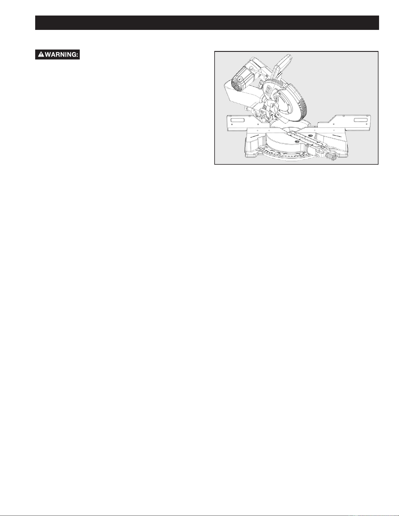
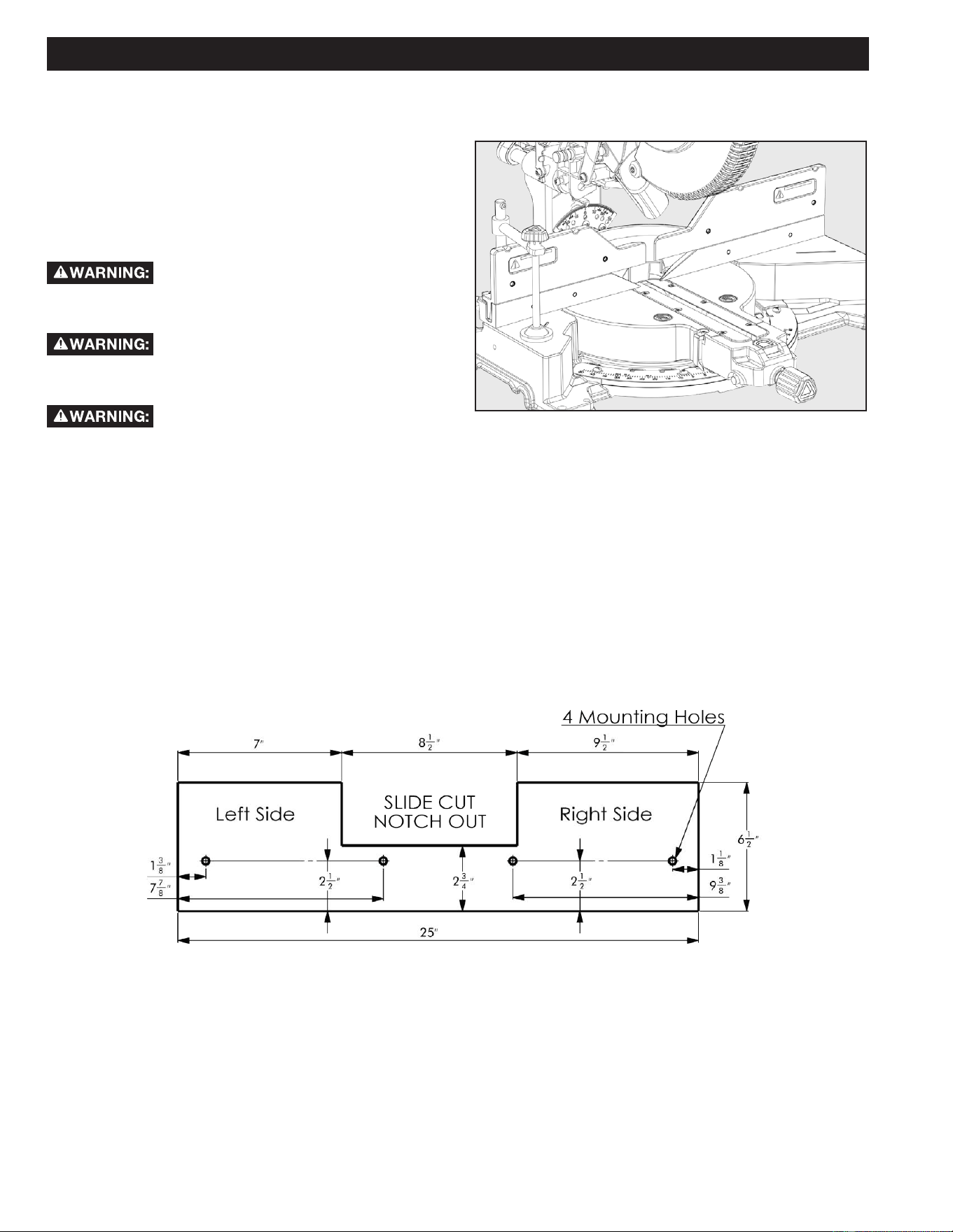
MOUNTING SAW TO STABLE SURFACE
To ensure safe and accurate operation, this
saw should be mounted to a stable and level surface such as a
sturdy workbench. To mount the tool to a stable surface, refer
to Figure 22 and do the following:
1. Locate the four mounting holes in the base of the saw
F25
.
2. Secure the tool to the mounting surface using 3/8 inch
diameter machine bolts, lock washers, and hex nuts
(not included). Make sure the bolts are long enough to
accommodate the saw base, lock washers, hex nuts,
and the thickness of the workbench.
3. Tighten all four bolts securely.
4. Check to make sure that the saw is secure before
operation.
Figure 22
F25F25
22
OPERATION
See Figures 23 and 24.
ALWAYS adjust and secure fence position to avoid contact
with the blade.
DO NOT start the Miter Saw without checking for interference
between the Blade and the Sliding Fence.
ALWAYS
recheck for such interference when changing
miter or bevel angles.
• DO NOT allow familiarity with tools to make you careless. Remember that a careless fraction of a second is sucient to
inict serious personal injury.
• ALWAYS wear eye protection with side shields and marked to comply with ANSI Z87.1 Failure to do so could result in objects
being thrown into your eyes, resulting in possible serious personal injury.
• DO NOT use any attachments or accessories not recommended by the manufacturer of this tool. The use of attachments or
accessories not recommended can result in serious personal injury.
• Before starting any cutting operation, clamp or bolt the compound miter saw to a workbench. NEVER operate the miter saw on
the oor or in a crouched position. Failure to heed this warning can result in serious personal injury.
• To avoid serious personal injury, ALWAYS tighten the miter lock knob and bevel lock handle securely before making a cut.
Failure to do so could result in serious injury due to movement of the control arm or miter table while making a cut.
• To avoid serious personal injury, KEEP hands outside the no hands zone, at least 4 inch from blade. NEVER perform any cutting
operation freehand (without holding workpiece securely against the fence). The blade could grab the workpiece if it slips or
twists.
• When using a work clamp or C-clamp to secure the workpiece, clamp workpiece on one side of the blade only. The workpiece
MUST remain free on one side of the blade to prevent the blade from binding in workpiece. The workpiece binding the blade will
cause motor stalling and kickback. This situation could cause an accident resulting in serious personal injury.
• NEVER move the workpiece or make adjustment to any cutting angle while the saw is running and the blade is rotating. Any slip
can result in contact with the blade causing serious personal injury.
• When cutting, DO NOT force the blade against the workpiece. Forcing the blade will cause a drop in motor RPM and increase
the risk of overheating the saw blade tips.
You may use this tool for the following purposes:
• Bevel cutting and compound cutting for crown moldings,
etc.
• Cross cutting wood.
• Cross cutting for moldings, door casings, picture frames,
etc.
• This saw is for cutting wood/wood-like products. The blade
provided is acceptable for wood/wood-like products cutting
ONLY.
Figure 24
Figure 23
23
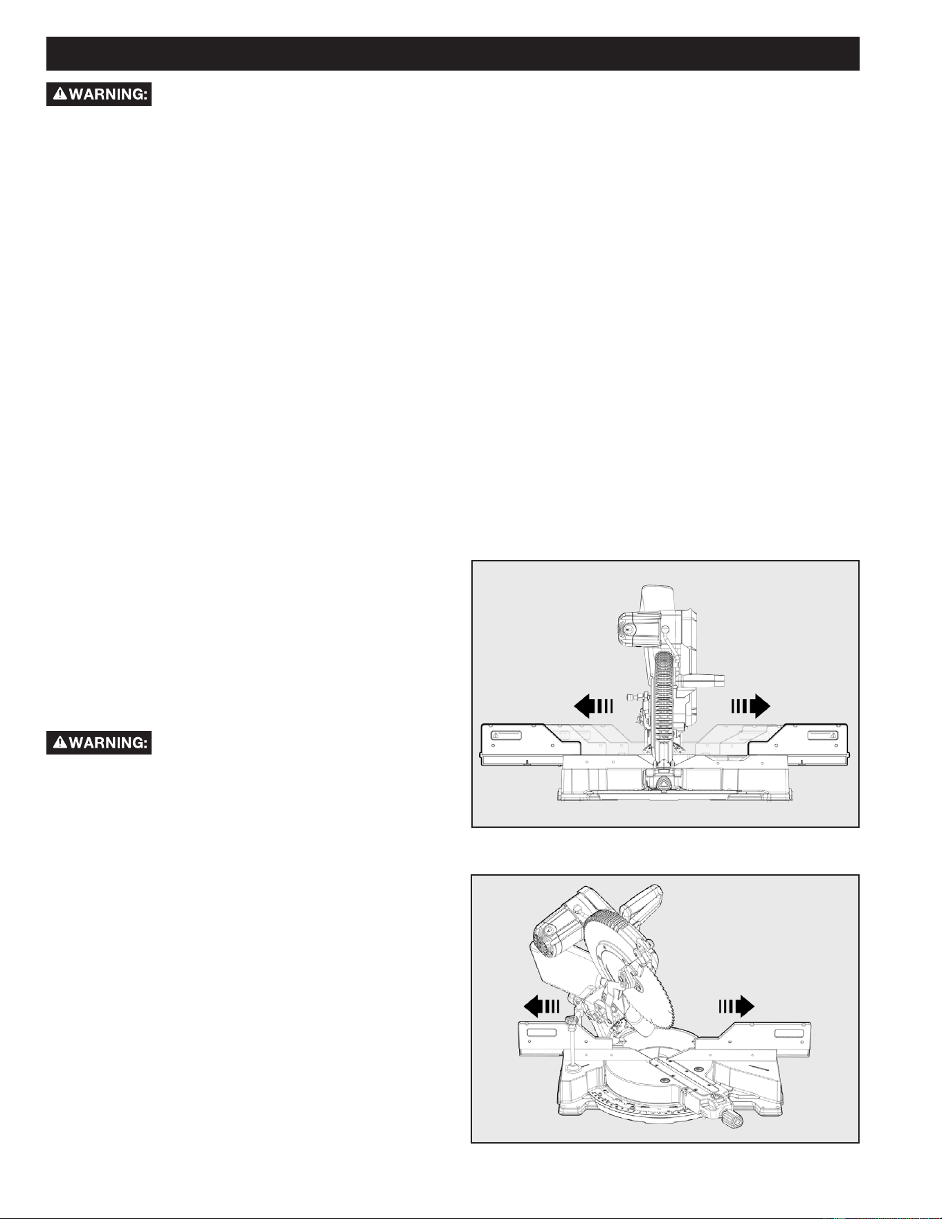
CUTTING WARPED MATERIAL
See Figure 25.
When attempting to cut warped material, the CONVEX face
should be against the fence.
See Figure 26.
NEVER position a piece of warped material with the CONCAVE
face or edge against the fence. It will pinch the blade near the
completion of the cut.
To avoid a kickback and to avoid serious
personal injury, NEVER position the concave edge of bowed or
warped material against the fence.
OPERATION
Figure 25
Figure 26
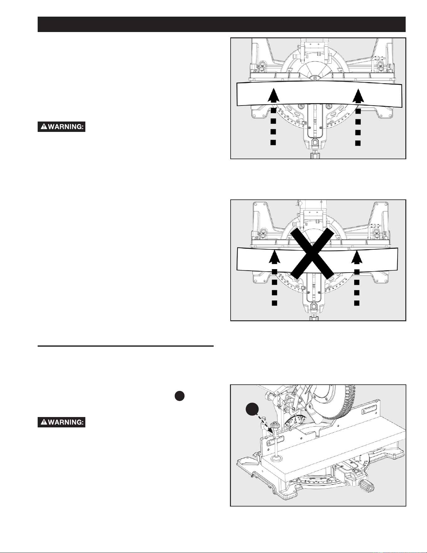
CLAMPING WIDE WORKPIECES
Figure 27
When cutting wide work pieces, such as 2 X 12 inch, clamp the
workpiece to the work table using a work clamp
F10
as shown
in Figure 27.
KEEP clamps away from the path of the
blade and blade guard assembly.
F10
24
OPERATION
Figure 29
POWER SWITCH LOCK
To prevent any unauthorized person from
operating this saw, a padlock (not included) should be installed
into the lock hole located on the power switch. See Figure 29.
Be sure padlock is fully closed and locked before leaving this
saw unattended.
Safety switch
F2
indicated in Figure 29 needs to be engaged
prior to operation of the machine.
ALWAYS disconnect the power supply
before installing or removing a lock onto the power switch.
Failure to do so could allow the power switch to engage by
accident, resulting in serious injury.
F2
BA
Figure 28
SUPPORTING LONG WORKPIECES
Additional support
A
may be used to make the workpiece lay
flat on the saw table. Use the included work clamp or a
C-clamp
B
to secure the workpiece to the miter saw table.
See Figure 28.
25
OPERATION
Figure 30
Figure 31
LOCK
UNLOCK
NON-SLIDING CUTS
Before turning the saw power ON, check to
make sure saw head and blade will not make contact with the
provided work clamp or fence during the cutting operation.
Position the work clamp and fence to avoid contact with the
miter saw head.
FOR CROSS CUTS
See Figures 30 and 31.
1. To use this saw as a traditional, non-sliding, miter saw:
slide the saw head into the fully retracted position and
engage the slide lock lever
F19
.
2. Unlock the miter lock knob
F23
, use your thumb to
push in the miter detent override button
F22
, and set
the miter arm angle to 0°. Use the miter scale and
indicator
F21
to locate the 0° miter position.
3. Release the miter detent override button
F22
and lock
the miter lock knob
F23
. Check that work table is
securely locked into position.
4. Release the saw head lock pin
F20
then raise the saw
head to its UP position.
5. Position the workpiece so that it is securely supported
by the saw table and fence. If the board is warped,
read and follow the instructions under “Cutting Warped
Material” in the “Operation” section of this manual.
6. Secure the workpiece to the table and against the
fence, using the provided clamp.
7. Before turning the power switch ON, perform a
simulated cut to check your cut alignment. Also check
to make sure the blade will not come into contact with
the provided work clamp, sliding fence or anything other
than the workpiece.
8. Engage the power ON switch. Allow the blade to reach
maximum speed.
9. Lower the saw blade through the workpiece.
10. Disengage the power switch and allow blade to come to
a complete stop before raising the saw head.
MITER CUTS
ALWAYS engage the slide lock lever
F19
before making any non-sliding cuts. Failure to engage this lock
could result in saw head movement during the cutting
operation.
To avoid serious personal injury, before turning the saw power ON, check to make sure saw head and blade will
not make contact with the provided work clamp or fence during the cutting operation. Position the work clamp and fence to avoid
contact with the miter saw head.
ALWAYS lock the miter lock knob
F23
before any cutting operation. Failure to do so may result in serious
personal injury.
See Figure 30.
1. To make miter cuts on this saw, using it as as traditional, non-sliding miter saw, slide the saw head into the fully retracted
position and engage the slide lock lever.
2. Rotate miter arm to one of the preset miter angles (0°,15°, 22.5°, 31.6°, or 45°).
3. Use the miter detent override button
F22
if your desired angle position is not provided.
4. Follow steps 3-10 of the Instructions for cross cuts in previous manual section.
F20
F19
F23
F24
F22
F21
26
OPERATION
UNLOCKUNLOCK
UNLOCKUNLOCK
LOOSENLOOSEN
Figure 33
Figure 32
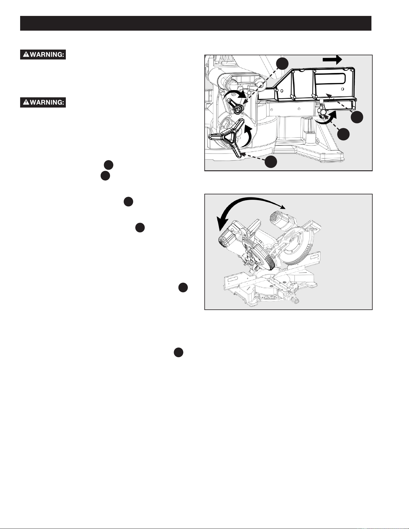
BEVEL CUTS
To avoid serious personal injury, before
turning the saw power ON, check to make sure saw head and
blade will not make contact with the provided work clamp or
fence during the cutting operation. Position the work clamp
and fence to avoid contact with the miter saw head.
ALWAYS lock the bevel lock handle before
any cutting operation. Failure to do so may result in serious
personal injury.
See Figure 32.
1. Follow Operation instructions in previous manual
section. Include the following adjustments before
cutting.
2. Loosen fence lock knob
A
, on left and right side, and
slide adjustable fence
F6
to allow proper spacing for
bevel cuts. Once proper spacing is set tighten fence lock
knob.
3. Loosen the bevel lock handle
F26
on the rear of the
machine.
4. While rmly supporting the saw head with one hand,
push back the bevel detent lever
F27
and swing the
saw head left or right to the required bevel angle.
5. If you are using one of the bevel detent positions
(0°,15°, 22.5°, 33.9°, or 45°), check to make sure the
bevel detent locks into the positive stop plate.
6. If you are using a bevel angle that is not one of the
common bevel detent positions, angle the saw to the
desired bevel angle and use the bevel lock handle
F26
to lock the head in place.
7. Turn the bevel lock handle clockwise to lock into
position.
NOTE: If your required bevel angle position is not provided
with one of the positive stop bevel detents; you can lock the
bevel position at any location using the bevel lock handle
F26
.
F27
F26
F6
A
27
OPERATION
Figure 34
COMPOUND MITER CUTS
To avoid serious personal injury, before
turning the saw power ON:
1. Check to make sure saw head and blade will not make
contact with the provided work clamp or fence during
the cutting operation.
2. Position the work clamp and fence to avoid contact with
the miter saw head.
See Figure 34.
A compound miter cut uses a combination of a miter angle
adjustment and bevel angle adjustment. Use the instructions
from “Miter Cuts” and “Bevel Cuts” to set your bevel and miter
angle before performing the operation instructions above.
NOTE: The miter angle and bevel angle are dependent upon
each other. If you adjust one of these it will change the other.
ALWAYS check both angles after making any adjustments.
28
OPERATION
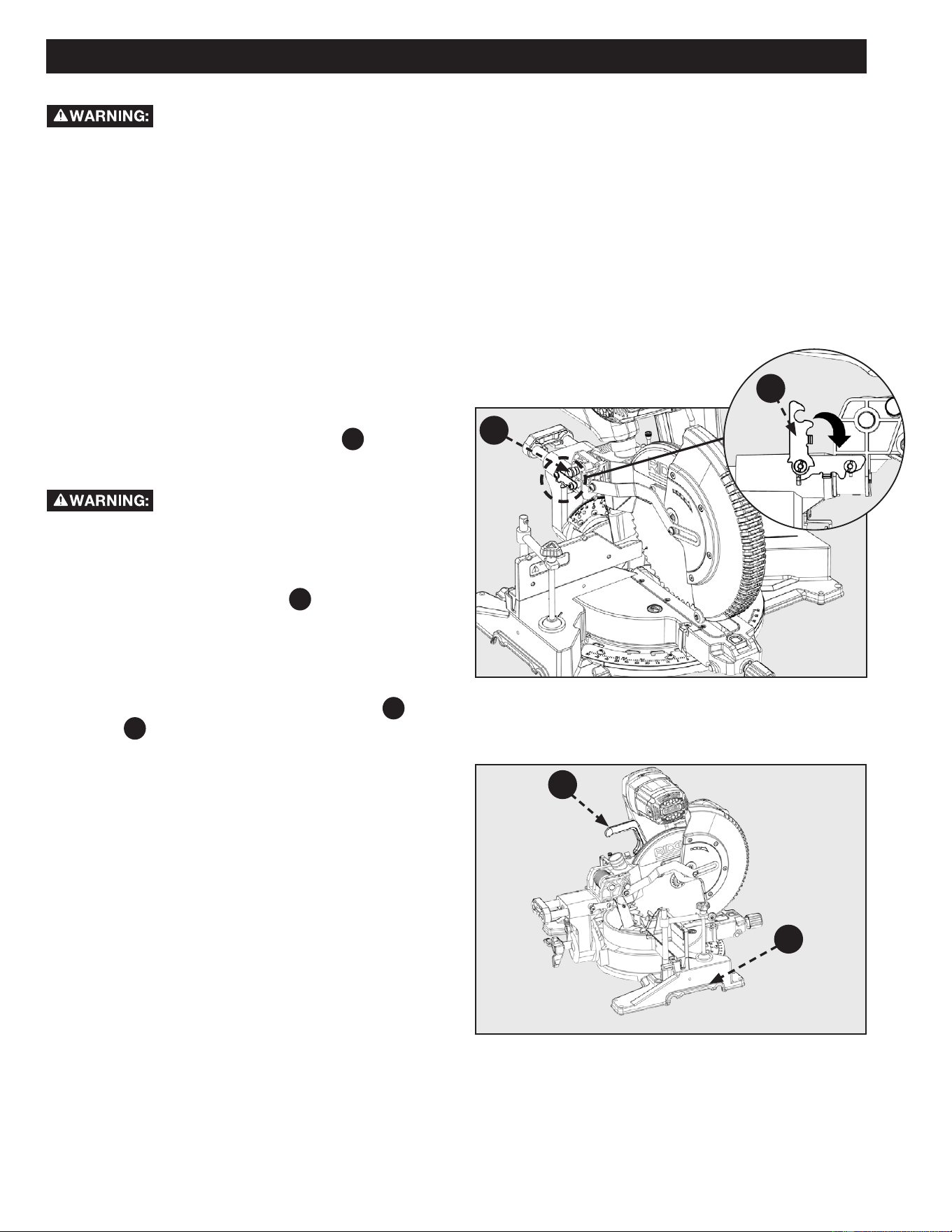
SLIDE CUTS
A slide cut should NEVER be performed by
pulling the saw toward you. Due to the blade rotation
direction, this can cause the saw blade to climb over the
workpiece and towards the operator. Failure to follow this
warning could result in serious personal injury.
Before turning the saw power ON, check to
make sure saw head and blade will not make contact with the
provided work clamp or fence during the cutting operation.
Position the work clamp and fence to avoid contact with the
miter saw head. Failure to follow this warning could result in
serious personal injury.
1. Check to make sure the slide lock lever
F19
and head lock
pin
F20
are disengaged. Raise the saw head to its UP
position.
2. Position the workpiece so that it is securely supported by
the saw table and fence. If the board is warped, read and
follow the instructions under “Cutting Warped Material” in
the “Operation” section of this manual.
3. Secure the workpiece to the table and against the fence,
using the provided clamp or a C-clamp.
To avoid serious personal injury, never clamp the workpiece
on both sides of the blade.
4. Before turning the power switch ON, perform a simulated
cut to check your cut alignment. Also check to make sure
the blade will not come into contact with the provided work
clamp, the fence or anything other than the workpiece.
5. Before turning the power switch ON, pull the saw arm
towards you until the blade is beyond the front edge
of your workpiece or until the saw arm is in the fully
EXTENDED position. The saw head should be in the full UP
position.
6. Engage the power ON switch. Allow the blade to reach
maximum speed.
7. Lower the saw blade through the workpiece and push the
saw head towards the fully RETRACTED position.
8. Disengage the power switch and allow blade to come to a
complete stop before raising the saw head.
See Figures 35 and 36.
To use this saw to make slide cuts follow the instructions
below. Slide cuts must ONLY be performed by pushing the
saw blade away from you and toward the back of the saw,
stopping at the fully RETRACTED position after each cut. See
warning above.
1
2
F20
F19
Figure 35
Figure 36

29
OPERATION
• The two edges of the molding that contact the ceiling and the wall are at angles that, when added together, equal exactly 90°.
Most crown molding has a top rear angle (the section that ts at against the ceiling) of 52° and a bottom rear angle (the
section that ts at against the wall) of 38°.
• To accurately cut crown molding for a 90° inside or outside corner, lay the molding with its broad back surface at on the miter
table and against the fence.
• The angles for crown moldings must be very precise. The bevel and miter angles are interdependent; changing one angle
changes the other angle as well.
• Since it is very easy for the work piece to shift, all settings should rst be tested on scrap molding. Also most wall corners do not
have angles of exactly 90°; therefore, you will need to ne-tune your settings.
• When cutting crown molding the bevel angle should be set at 33.85°.
• The miter angle should be set at 31.62° either right or left, depending on the desired cut for the application. See the chart on
below for correct angle settings and correct positioning of crown molding on the work table.
TIPS FOR CUTTING CROWN MOLDING
Bevel Angle Setting Type of Cut Steps
33.85° Left side, inside corner
1. Top edge of molding against fence
2. Miter table set right 31.62°
3. Save left end of cut
33.85° Right side, inside corner
1. Bottom edge of molding against fence
2. Miter table set left 31.62°
3. Save left end of cut
33.85° Left side, outside corner
1. Bottom edge of molding against fence
2. Miter table set left 31.62°
3. Save right end of cut
33.85° Right side, outside corner
1. Top edge of molding against fence
2. Miter table set right 31.62°
3. Save right end of cut
30
OPERATION
AUXILIARY FENCE
See Figure 37.
For cutting certain workpieces, you may require a larger
fence surface area to accommodate an auxiliary fence with a
workpiece. The auxiliary fence should be made using 3/4 inch
thick wood. Use the mounting holes (in bold) which are pre-
drilled in the fence to attach an auxiliary fence.
NEVER use auxiliary fence which interferes
or makes contact with saw head. ALWAYS check for clearance
between auxiliary fence and saw head before making cuts.
To make slide cuts using an auxiliary fence, a
notch MUST be cut out in the auxiliary fence prior to attaching
to saw fence.
The auxiliary fence can ONLY be used with
the 0° bevel angle. Remove the auxiliary fence before making
a bevel cut.
Figure 38
See Figure 38 for auxiliary fence dimensions.
1. Place auxiliary fence wood against miter saw fence. See Figure 37. The maximum height for this wood must not exceed
5.5 inch. Check to make sure auxiliary fence does make contact with saw head, check with saw head in the full DOWN and
fully RETRACTED position.
2. Mark the hole locations on the backside of the auxiliary fence board.
3. Drill the marked hole locations all the way through the auxiliary fence. Make sure the screw heads are level with or
below the surface of the auxiliary fence.
4. Fasten the auxiliary fence using at head screws. Secure from behind using at washers and nuts.
5. Make a full depth cut through the auxiliary fence, to create the blade slot.
6. The notch shown in Figure 38 must be cut out in order to make slide cuts using the auxiliary fence.
Figure 37
31
OPERATION
Figure 39
Figure 40
Figure 41
X
X
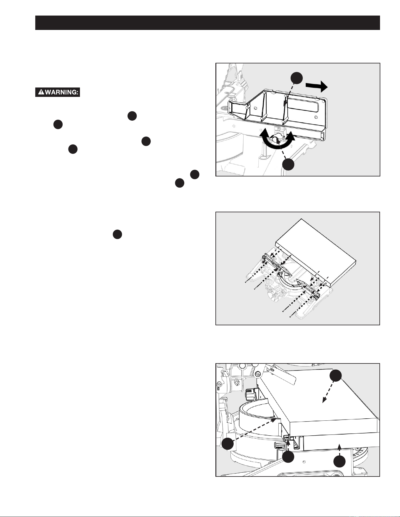
EXPAND WORKTABLE AREA
This saw is designed to allow for large capacity cuts up to
2 x 12 inch. In order to make these cuts you will need to
configure your saw appropriately.
DO NOT use an auxiliary table board which
will not fully support the workpiece during cutting operation.
1. Loosen the fence lock knob
A
. Slide the upper fences
B
completely out of their tracks and set them to the
side. See Figure 39.
2. Flip the back fence support tabs
F
into position. The
Tabs
F
are on both the left and right sides of the
lower (fixed) fence. These will function as your
workpiece backstop. See Figure 40.
3. You will need to add a 2 x 12 auxiliary table board
C
to support your large capacity workpiece
D
. See
Figure 41.
NOTE: The Auxiliary Table Board should be as wide as the
lower (xed) fence and secured to the lower fence using
wood screws, see Figure 41.
4. The large capacity workpiece is supported against the
step in the xed fence
E
Figure 41.
TIGHTEN
LOOSEN
B
A
D
E
C
F
32
MAINTENANCE
To reduce the risk of injury, turn unit off and
disconnect it from power source before cleaning or servicing,
before installing and removing accessories, before adjusting
when making repairs. An accidental start-up can cause serious
injury.
KEEP MACHINE CLEAN
Periodically blow out all air passages with
dry compressed air. All plastic parts should be cleaned with a
soft damp cloth. NEVER use solvents to clean plastic parts.
They could possibly dissolve or otherwise damage the material.
Wear certified safety equipment for eye, hearing and
respiratory protection while using compressed air.
Empty dust bag frequently.
When servicing, use only identical replacement parts. Use of
any other parts may create a hazard or cause product damage.
GENERAL MAINTENANCE
NEVER use solvents when cleaning plastic parts. Most plastics
are susceptible to damage from various types of commercial
solvents and may be damaged by their use. Use clean cloths to
remove dirt, dust, oil, grease, etc.
DO NOT at any time let brake fluids,
gasoline, petroleum-based products, penetrating oils, etc.,
come in contact with plastic parts. Chemicals can damage,
weaken or destroy plastic which may result in serious personal
injury.
Electric tools used on fiberglass material, wallboard,
spackling compounds, or plaster are subject to accelerated
wear and possible premature failure because the fiberglass
chips and grindings are highly abrasive to bearings, brushes,
commutator, etc. Consequently, we DO NOT recommend
using this tool for extended work on these types of materials.
However, if you do work with any of these materials, it is
extremely important to clean the tool using compressed air.
LUBRICATION
All of the bearings in this tool are lubricated with a sufficient
amount of high-grade lubricant for the life of the unit under
normal operating conditions. Therefore, no further lubrication
is required.
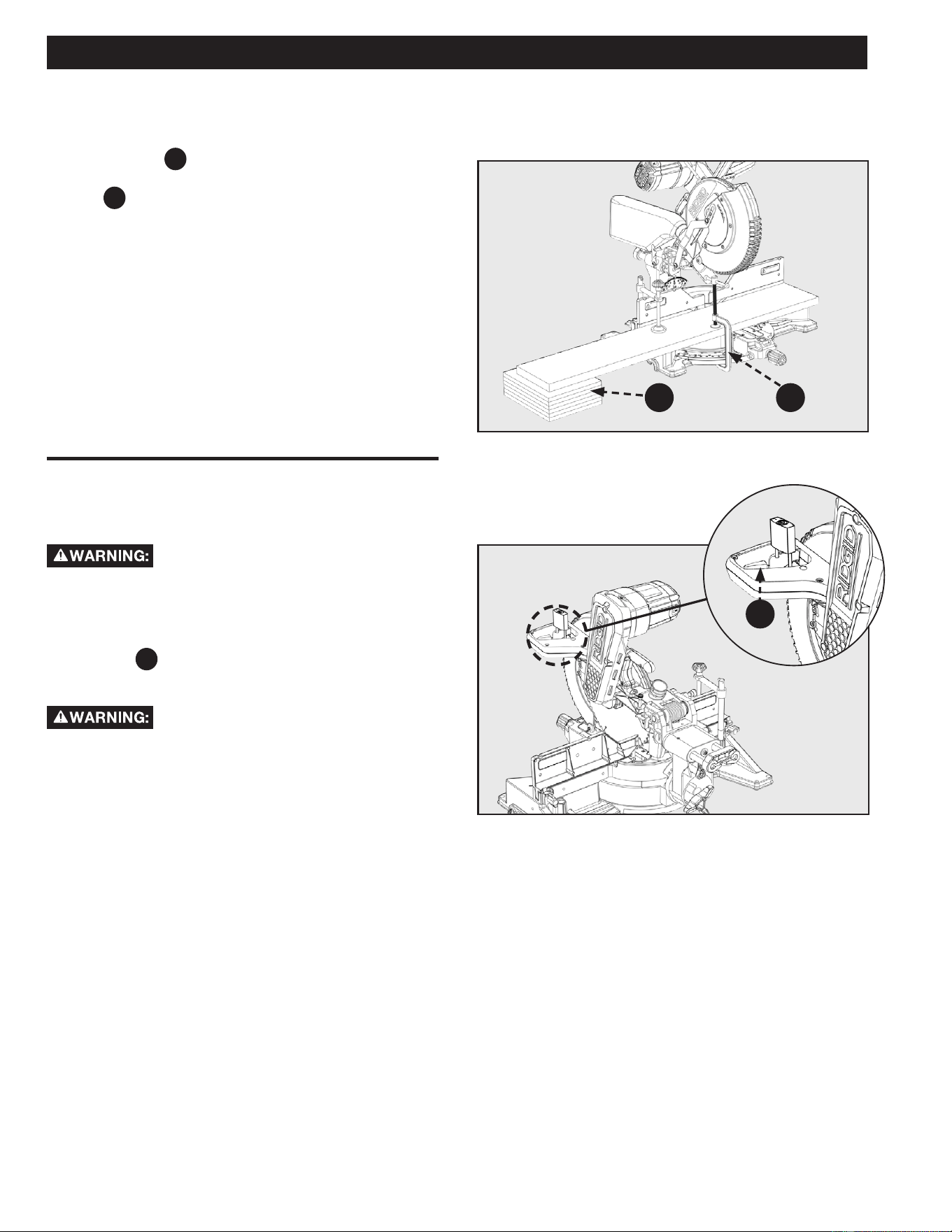
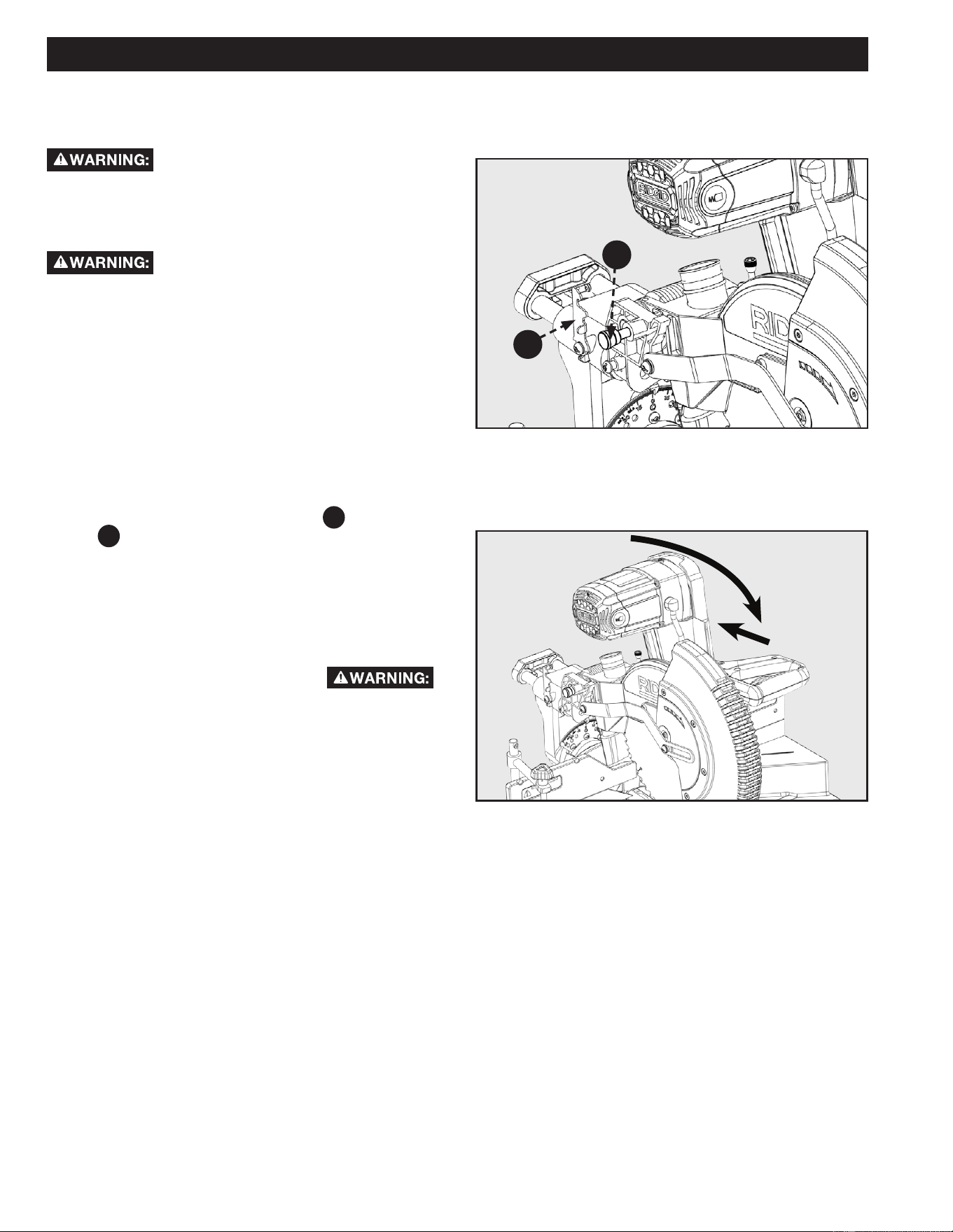
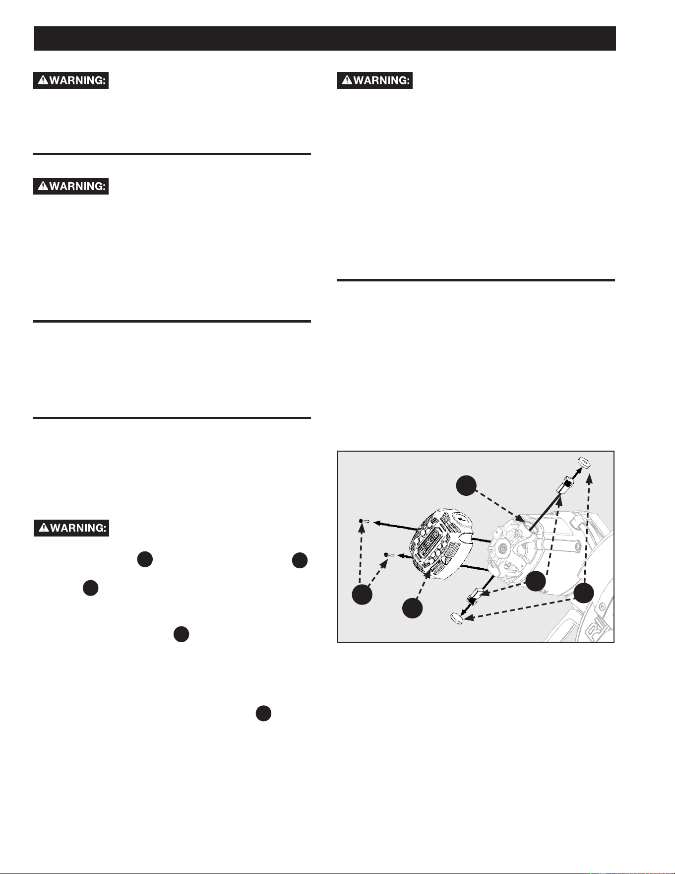
BRUSH REPLACEMENT
The motor on this saw features externally accessible brush
assemblies that should be periodically checked for wear. If the
brushes need to be replaced, see to Figure 42 and proceed as
follows:
1. Unplug the saw.
Failure to unplug the saw could result in
accidental starting causing serious personal injury.
2. Loosen Screws
A
and remove motor end cap
F17
.
Using a athead screwdriver carefully remove the brush
cap
B
.
NOTE: Remove the cap slowly. The brush assembly is spring-
loaded and will pop out once the cap is removed.
3. Remove brush assembly
C
.
4. Inspect both brushes. If either has less than 1/4 inch
length of carbon remaining, both brushes should be
replaced.
NOTE: DO NOT replace one side without replacing the other.
5. Insert both brushes into the brush tubes
D
, making
sure the curvature of the brushes matches curvature of
motor. Brush assembly should move freely within the
tube.
6. Carefully replace the brush cap, ensuring that the brush
cap is clean and properly aligned so the threads don’t
strip.
7. Tighten brush cap securely. DO NOT over-tighten.
C
B
Figure 42
D
F17
A

33
TROUBLESHOOTING
For assistance with your machine, visit our website at www.ridgid.com for a list of service centers or call RIDGID® Customer Service
at (toll free) 1-888-359-4778 or email at [email protected].
FAILURE TO START
If your machine fails to start, check to make sure the prongs on the cord plug are making good contact in the receptacle, and check
reset button on GFCI - Ground Fault Circuit Interrupt (If applicable). Also, check for blown fuses or open circuit breakers in your power
line.
ACCESSORIES
A complete line of accessories is available from your RIDGID®
Supplier, RIDGID®
Factory Service Centers, and RIDGID® Authorized
Service Centers. Please visit our Web Site www.ridgid.com for an on-line catalog or for the name or your nearest supplier.
Since accessories other than those oered by RIDGID
®
have not been tested with this product, use of
such accessories could be hazardous. For safest operation, only RIDGID
®
recommended accessories
should be used with this product.
Problem Possible Cause Solution
Saw will not start 1. Saw un-plugged.
2. Fuse blown or circuit breaker tripped.
3. Damaged power cord.
4. Worn out brushes.
1. Make sure the saw is plugged in.
2. Replace fuse or reset circuit breaker.
3. Contact local authorized Service Center to
have cord replaced.
4. Contact local authorized Service Center
to have brushes replaced if you cannot
replace them yourself. Refer to page 32.
Saw makes poor cuts 1. Dull saw blade
2. Blade not mounted properly.
3. Residue on pitch or blade.
4. Incorrect type of blade installed.
1. Replace blade. Refer to page 14.
2. Correct blade tment. Refer to page 14.
3. Remove and clean the blade.
4. Change the blade. Refer to page 14.
Blade not getting up to speed 1. Extension cord too small gauge or too long.
2. Low current rating from the source.
1. Replace with correct size extension cord
Refer to page 10.
2. Contact your electric company.
Machine has excessive vibration
1. Saw is not mounted securely to stand or
workbench.
2. Miter saw stand or workbench on uneven
oor.
3. Damaged saw blade.
1. Tighten all mounting hardware. Refer to
page 21.
2. Reposition on level surface. Refer to page
21.
3. Replace blade. Refer to page 14.
Miter cuts are not accurate 1. Miter scale not reading correctly.
2. Blade is not square to fence.
3. Blade is not perpendicular to table.
4. Workpiece could be moving during
operation.
1. Check and adjust. Refer to page 16.
2. Check and adjust. Refer to page 16.
3. Check and adjust. Refer to page 15.
4. Clamp workpiece securely to fence.
Material binding in the blade
1. Material could be bowed or could be cutting
through knots.
1. Refer to page 23.

34
PARTS, SERVICE OR WARRANTY ASSISTANCE
DPEC
2651 New Cut Road
Spartanburg, SC 29303
Proof of purchase must be presented when requesting warranty
service.
Limited to RIDGID® stationary power tools purchased 2/1/21
and after. This product is manufactured by DPEC. The trademark
is licensed from RIDGID
®, Inc. All warranty communications
should be directed to Customer Service attn: RIDGID
® Stationary
Power Tool Technical Service at (toll free) 1-888-359-4778.
90-DAY SATISFACTION GUARANTEE POLICY
During the rst 90 days after the date of purchase, if you are
dissatised with the performance of this RIDGID
® Stationary
Power Tool for any reason you may return the tool to the dealer
from which it was purchased for a full refund or exchange. To
receive a replacement tool you must present proof of purchase
and return all original equipment packaged with the original
product. The replacement tool will be covered by the limited
warranty for the balance of the 5 YEAR service warranty period.
WHAT IS COVERED UNDER THE 5 YEAR
LIMITED SERVICE WARRANTY
This warranty on RIDGID® Stationary Power Tools covers all
defects in workmanship or materials in this RIDGID
® tool for
ve years following the purchase date of the tool. Warranties
for other RIDGID
® products may vary.
HOW TO OBTAIN SERVICE
To obtain service for this RIDGID® tool you must call RIDGID®
Customer Service at (toll free) 1-888-359-4778 or email us
at [email protected]. When requesting
warranty service, you must present the original dated sales
receipt. The authorized service center will repair any faulty
workmanship, and either repair or replace any part covered
under the warranty, at our option, at no charge to you.
WHAT IS NOT COVERED
This warranty applies only to the original purchaser at retail
and may not be transferred. This warranty only covers defects
arising under normal usage and does not cover any malfunction,
failure or defect resulting from misuse, abuse, neglect,
alteration, modication or repair by other than an authorized
service center for RIDGID
® branded stationary power tools.
Consumable accessories pro vided with the tool such as, but not
limited to, blades, bits and sand paper are not covered.
RIDGID® MAKE NO WARRANTIES, REPRESENTATIONS OR
PROM ISES AS TO THE QUALITY OR PERFORMANCE OF
ITS POWER TOOLS OTHER THAN THOSE SPECIFICALLY
STATED IN THIS WARRANTY.
ADDITIONAL LIMITATIONS
To the extent permitted by applicable law, all implied warranties,
including warranties of MERCHANTABILITY or FIT NESS FOR A
PARTICULAR PURPOSE, are disclaimed. Any implied warranties,
including warranties of merchantability or tness for a particular
purpose, that cannot be disclaimed under state law are limited to
ve years from the date of purchase. RIDGID
® is not responsible
for direct, indirect, incidental or consequential damages. Some
states do not allow limitations on how long an implied warranty
lasts and/or do not allow the exclusion or limitation of incidental
or consequential damages, so the above limitations may not
apply to you. This warranty gives you specic legal rights, and
you may also have other rights which vary from state to state.
RIDGID® STATIONARY POWER TOOL
5 YEAR LIMITED SERVICE WARRANTY

35
NOTES

OPERATOR’S MANUAL
12 inch Max Reach Miter Saw
R4231
DPEC
2651 New Cut Road
Spartanburg, SC 29203
©2021
RIDGID® is a registered trademark and used under license.
Customer Service Information:
For parts or service, do not return this product to the store. Contact your nearest
RIDGID® authorized service center. Be sure to provide all relevant information when
you call or visit. For the location of the authorized service center nearest you, please
call 1-888-359-4778 or email us at RidgidMiterSaws@Ridgidproducts.com.
MODEL NO.*_____________________SERIAL NO.___________________________
*Model number on product may have additional letters at the end. These letters designate manufacturing
information and should be provided when calling for service.
DPEC006145
08-06-21 REV6