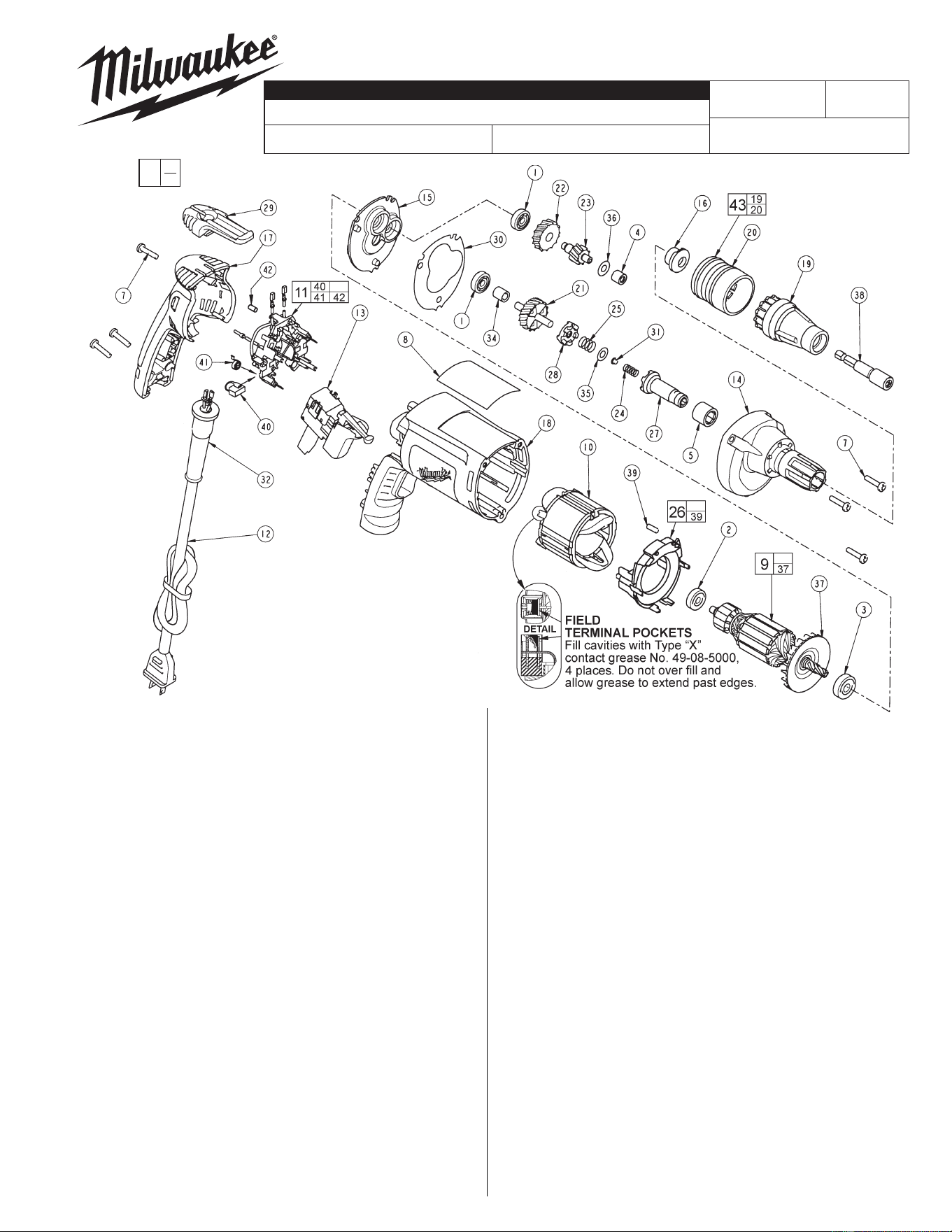
FIG. PART NO. DESCRIPTION OF PART NO. REQ.
1 02-04-0640 Ball Bearing (2)
2 02-04-0645 Ball Bearing (1)
3 02-04-0852 Ball Bearing (1)
4 02-50-2400 Needle Bearing (1)
5 02-50-3245 Needle Bearing (1)
7 06-82-7275 7-18 x 3/4 Slotted Plastite Torx T-20 (6)
8 12-99-2665 Service Nameplate (1)
9 16-10-2205 Armature (1)
10 18-07-2200 Field (1)
11 22-18-1210 Brush Card Assembly (1)
12 22-64-6510 Cord Assembly (1)
13 23-66-2605 Switch (1)
14 28-14-2380 Gearcase (1)
15 28-28-2315 Diaphragm (1)
16 30-37-0055 Tek Nose Guide (1)
17 31-15-2010 Handle Halve (1)
18 31-50-4010 Motor Housing (1)
19 31-51-0104 Tek Locator (1)
20 31-58-0515 Snap Sleeve (1)
21 32-10-0525 Clutch Gear Assembly (1)
22 32-40-0100 Intermediate Gear (1)
23 36-66-0120 Intermediate Shaft (1)
24 40-50-0095 Separator Spring (1)
25 40-50-8515 Bias Spring (1)
26 42-14-0460 Baffl e Assembly (1)
27 42-66-0715 Clutch Chuck Assembly (1)
28 42-70-0310 Drive Clutch (1)
29 42-70-5280 Belt Clip (1)
30 43-44-0985 Gasket (1)
31 44-60-0505 Thrust Pin (1)
32 44-76-0210 Cord Protector (1)
34 45-36-1280 Spacer (1)
35 45-88-0555 Clutch Thrust Washer (1)
36 45-88-7990 Thrust Washer (1)
WIRING INSTRUCTION
REVISED BULLETIN DATE
SERVICE PARTS LIST
MILWAUKEE ELECTRIC TOOL CORPORATION
13135 W. LISBON RD., BROOKFIELD, WI 53005
Drwg. 2
BULLETIN NO.
STARTING
SERIAL NO.
54-42-6251
58-01-1806
SPECIFY CATALOG NO. AND SERIAL NO. WHEN ORDERING PARTS
6790-20
CATALOG NO.
DEPTH LOCATING SCREWDRIVER
June 2011
179B
FIG. PART NO. DESCRIPTION OF PART NO. REQ.
37 22-84-0845 Fan Assembly (1)
38 49-66-4533 5/16 Hex Socket (1)
39 45-30-0030 Slug (2)
40 22-18-1310 Brush Assembly (2)
41 23-52-1610 Brush Spring (2)
42 45-30-0035 Slug (1)
43 49-26-1082 TEK Locator Assembly (1)
LUBRICATION (Type "Y" Grease, No. 49-08-5270)
• Fill the 3 enlarged clutch pockets of the clutch gear assembly (21)
with .5 gm. (.02 oz.) grease.
• Apply the same amount of grease in the bias spring (25).
• Apply in total .5 gm. (.02 oz.) grease to the clutch thrust washer
(35), thrust pin (31) and separator spring (24).
• Place 3.6 gm. (.13 oz.) of grease on top of the inserted
intermediate needle bearing (4).
• Place 13 gm. (.46 oz.) of grease at the armature pin location in the
gearcase (14) and fi ll to slightly above the intermediate gear (22).
• Apply a light fi lm of grease to the lead chamfer of the clutch
chuck (27) prior to assembly.
Before assembly, lightly coat all press fi t areas with
lightweight spindle oil.
EXAMPLE:
Component Parts (Small #) Are Included
When Ordering The Assembly (Large #).
00
0
FIG. NOTES:
4 Needle bearings to be pressed fl ush to
.010 under fl ush, from end which has the
vendor identifi cation.
5 Needle bearing to have it's seal toward the
front of the tool. Needle bearing to be
pressed .133/.143 under fl ush.
Cat. No.
31-53-0205
Lock Button
Plug
54-42-6250
= Part number change from
previous service parts list.