


3
PRODUCT RECORD
In the space below, record the date of purchase, model and serial number of your product.
You will find the model and serial number printed on an identification label located on the
inside right lip of the oven cavity. Have these items of information available whenever you
contact Sears concerning your product.
Model No.
Date of Purchase
Serial No.
Save these instructions and attach your sales receipt for future reference.

4
Kenmore Limited Warranty
Kenmore
®
products are sold and distributed by Kenmore and Kenmore authorized
distributors and licensees in various countries.
For information on the limited warranty and authorized provider applicable to your product
and country please visit: https://www.kenmore.com/warranty-information/
For a printed copy please contact us at 1-844-553-6667 or at the address below:
ATTN: Kenmore Warranty Request
5407 Trillium Suite B120
Hoffman Estates, IL 60192

5
TABLE OF CONTENTS
RANGE SAFETY.................................................................................................................6
PARTS AND FEATURES..................................................................................................11
CONTROL PANEL............................................................................................................12
COOKTOP USE.................................................................................................................15
OVEN USE.......................................................................................................................21
RANGE CARE..................................................................................................................32
TROUBLESHOOTING.....................................................................................................37
Installation Requirements............................................................................................40
Installation Instructions.................................................................................................45
6
Your safety and the safety of others are very important.
We have provided many important safety messages in this manual and on your appliance.
Always read and obey all safety messages.
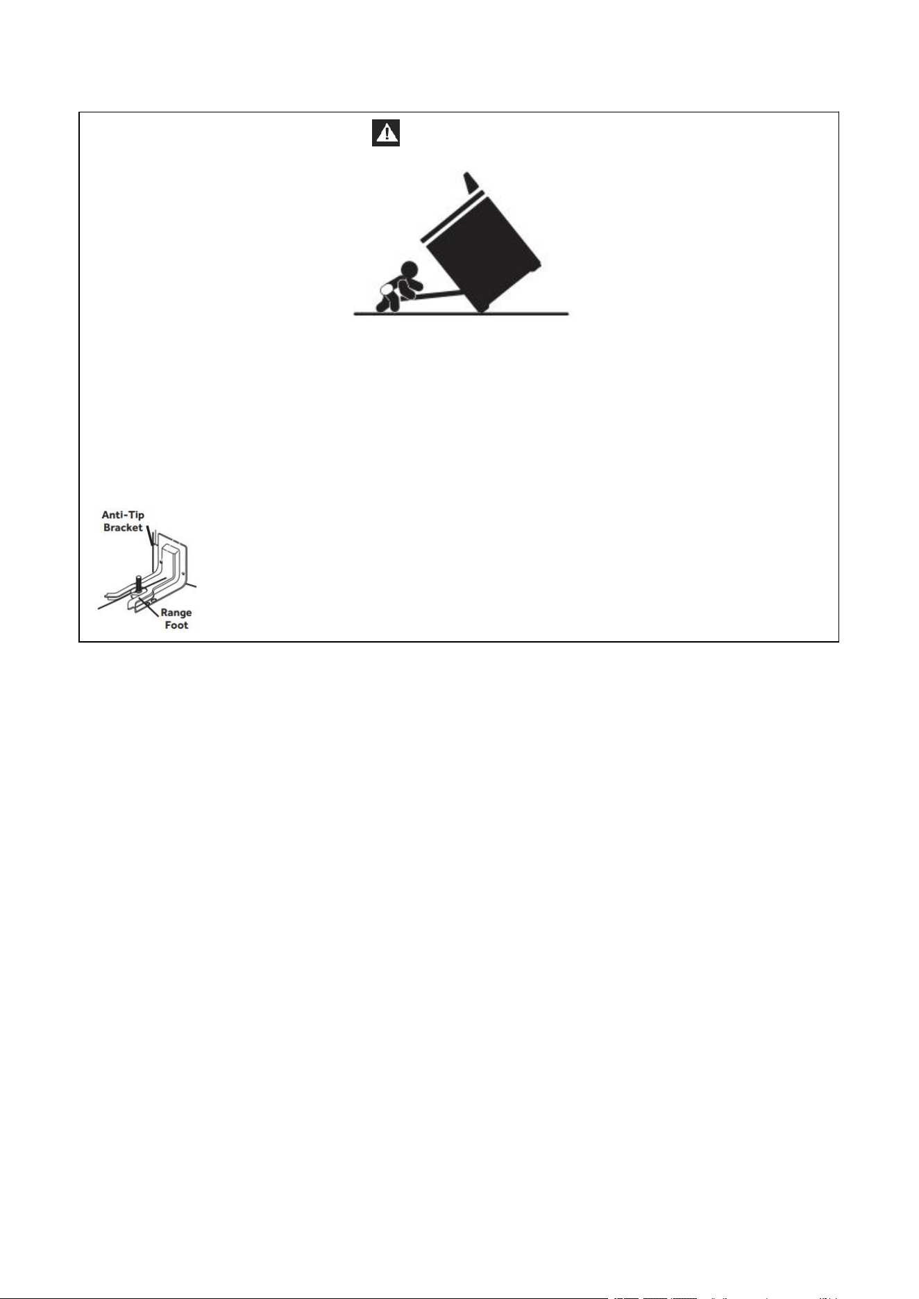
This is the safety alert symbol.
This symbol alerts you to potential hazards that can kill or hurt you
and others. All safety messages will follow the safety alert symbol
and either the word
“DANGER,” “WARNING” or “CAUTION.”
These words mean:
DANGER
An imminently hazardous situation. You could be
killed or seriously injured if you don’t immediately
follow instructions.
WARNING
A potentially hazardous situation which, if not
avoided, could result in death or serious bodily
injury.
CAUTION
A potentially hazardous situation which, if not
avoided, may result in moderate or minor injury.
All safety messages will tell you what the potential hazard is, tell you how to reduce the
chance of injury, and tell you what can happen if the instructions are not followed.
RANGE SAFETY
7
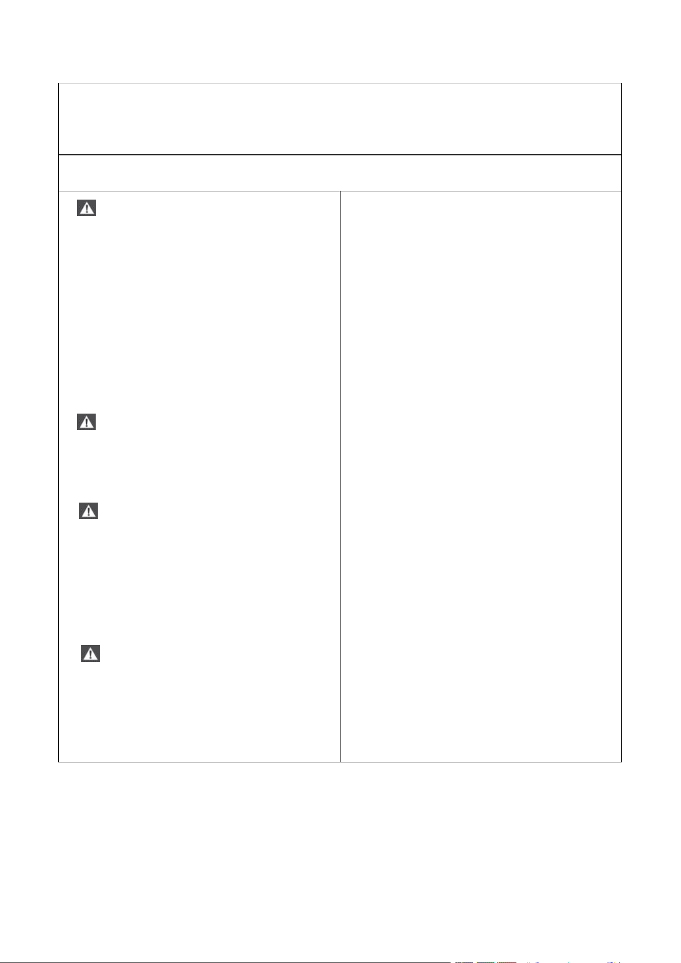
THE ANTI-TIP BRACKET
WARNING
Tip Over Hazard
A child or adult can tip the range and be killed.
Connect anti-tip bracket to rear range foot.
Reconnect the anti-tip bracket, if the range is moved.
See the installation instructions for details.
Failure to follow these instructions can result in death or serious burns to children and
adults.
Making sure the anti-tip bracket is installed:
• Slide range forward.
• Look for the anti-tip bracket securely attached to floor.
• Slide range back so rear range foot is under anti-tip
bracket.
8
IMPORTANT SAFETY
INSTRUCTIONS
WARNING: To reduce the risk of fire, electrical shock, injury to persons, or damage when
using the range, follow basic precautions, including the following:
• WARNING TO REDUCE THE RISK OF
TIPPING OF THE RANGE, THE RANGE MUST
BE SECURED BY PROPERLY INSTALLED
ANTI-TIP DEVICES. TO CHECK IF THE
DEVICES ARE INSTALLED PROPERLY, SLIDE
RANGE COMPLETELY FORWARD, LOOK
FOR ANTI-TIP BRACKET SECURELY
ATTACHED TO THE FLOOR BEHIND THE
RANGE AND SLIDE RANGE COMPLETELY
BACK UNTIL THE REAR RANGE FOOT IS
UNDER ANTI-TIP BRACKET.
• WARNING NEVER use this appliance
as a space heater to heat or warm the room.
Doing so may result in carbon monoxide
poisoning and overheating of the oven.
• WARNING NEVER cover any slots,
holes or passages in the oven bottom or
cover an entire rack with materials such as
aluminum foil. Doing so blocks airflow
through the oven and may cause carbon
monoxide poisoning. Aluminum foil linings
may also trap heat, causing a fire hazard.
• CAUTION Do not store items of
interest to children in cabinets above a
range or on the back guard of a range –
children climbing on the range to reach
items could be seriously injured.
• Do Not Leave Children Alone – Children
should not be left alone or unattended in
area where the range is in use. They should
never be allowed to sit or stand on any part
of the range.
• Wear Proper Apparel – Loose-fitting or
hanging garments should never be worn
while using the range.
• User Servicing – Do not repair or replace
any part of the range unless specifically
recommended in the manual. All other
servicing should be referred to a qualified
technician.
• Storage in or on the Range – Flammable
materials should not be stored in an oven or
near surface units.
• Do Not Use Water on Grease Fires -
Smother fire or flame or use dry chemical or
foam-type extinguisher.
• Use Only Dry Potholders – Moist or damp
potholders on hot surfaces may result in
burns from steam. Do not let potholder
touch hot heating elements. Do not use a
towel or other bulky cloth.

9
IMPORTANT SAFETY
INSTRUCTIONS
• DO NOT TOUCH SURFACE UNITS OR
AREAS NEAR UNITS – Surface units may be
hot even though they are dark in color.
Areas near surface units may become hot
enough to cause burns. During and after
use, do not touch, or let clothing or other
flammable materials contact surface units
or areas near units until they have had
sufficient time to cool. Among those areas
are the cooktop and surfaces facing the
cooktop.
• Never Leave Surface Units Unattended at
High Heat Settings – Boil over causes
smoking and greasy spillovers that may
ignite.
• Glazed Cooking Utensils – Only certain
types of glass, glass/ceramic, ceramic,
earthenware, or other glazed utensils are
suitable for range-top service without
breaking due to the sudden change in
temperature.
• Utensil Handles Should Be Turned Inward
and Not Extend Over Adjacent Surface Units
– To reduce the risk of burns, ignition of
flammable materials, and spillage due to
unintentional contact with the utensil, the
handle of a utensil should be positioned so
that it is turned inward, and does not extend
over adjacent surface units.
• Clean Cooktop With Caution – If a wet
sponge or cloth is used to wipe spills on a
hot cooking area, be careful to avoid steam
burn. Some cleaners can produce noxious
fumes if applied to a hot surface.
• Use Care When Opening Door – Let hot air
or steam escape before removing or
replacing food.
• Do Not Heat Unopened Food Containers –
Build-up of pressure may cause container to
burst and result in injury.
• Keep Oven Vent Ducts Unobstructed.
• Placement of Oven Racks – Always place
oven racks in desired location while oven is
cool. If rack must be moved while oven is
hot, do not let potholder contact hot
heating element in oven.
• DO NOT TOUCH HEATING ELEMENTS OR
INTERIOR SURFACES OF OVEN – Heating
elements may be hot even though they are
dark in color. Interior surfaces of an oven
become hot enough to cause burns. During
and after use, do not touch, or let clothing or
other flammable materials contact heating
elements or interior surfaces of oven until
they have had sufficient time to cool. Other
surfaces of the appliance may become hot
enough to cause burns – among these
surfaces are oven vent openings and
surfaces near these openings, oven doors,
and windows of oven doors.
10
IMPORTANT SAFETY
INSTRUCTIONS
• Proper Installation – The range, when
installed, must be electrically grounded in
accordance with local codes or, in the
absence of local codes, with the National
Electrical Code, ANSI/NFPA 70. In Canada,
the range must be electrically grounded in
accordance with Canadian Electrical Code.
Be sure the range is properly installed and
grounded by a qualified technician.
• Disconnect the electrical supply before
servicing the appliance.
• Injuries may result from the misuse of
appliance doors or drawers such as
stepping, leaning, or sitting on the doors or
drawers.
• Maintenance – Keep range area clear and
free from combustible materials, gasoline,
and other flammable vapors and liquids.
For units with ventilating hood –
• Clean Ventilating Hoods Frequently –
Grease should not be allowed to accumulate
on hood or filter.
• When flambé cooking under the vent
hood, turn the fan on.
READ AND SAVE THESE
INSTRUCTIONS
State of California Proposition 65 Warnings:
WARNING This product contains bisphenol A(BPA), which is known to the state of
California to cause birth defects, or other reproductive harm, and lead and lead
compounds, which are known to the state of California to cause cancer and birth defects or
other reproductive harm.
For more information, go to : www.P65Warnings.ca.gov.
11
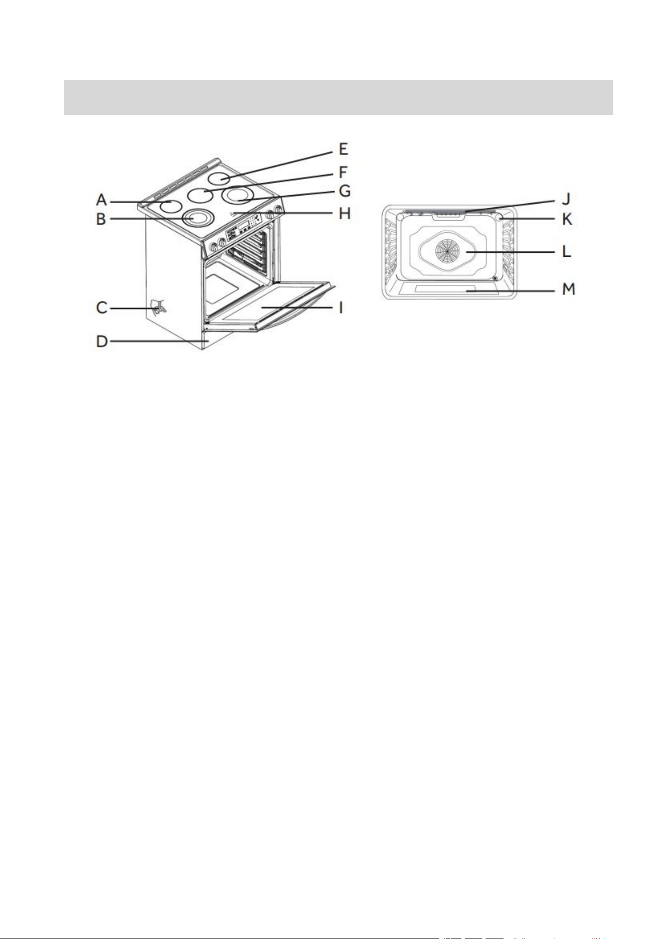
A. Left Rear Burner
B. Left Front Burner
C. Anti-tip Bracket
D. Kick Plate
E. Right Rear Burner
F. Middle Burner
G. Right Front Burner
H. Hot Surface Indicator Lights
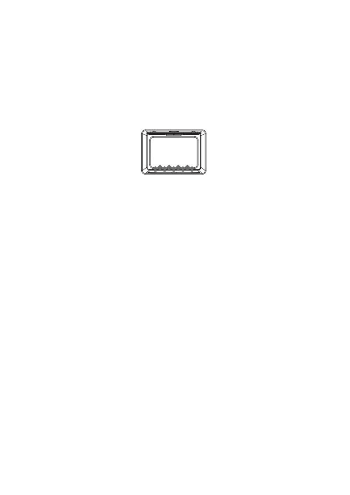
I. Oven Door Window
J. Broil Element
K. Oven Lights
L. Convection Fan and Rear
Element (not visible)
M. Bottom Element (not visible)
PARTS AND FEATURES
12
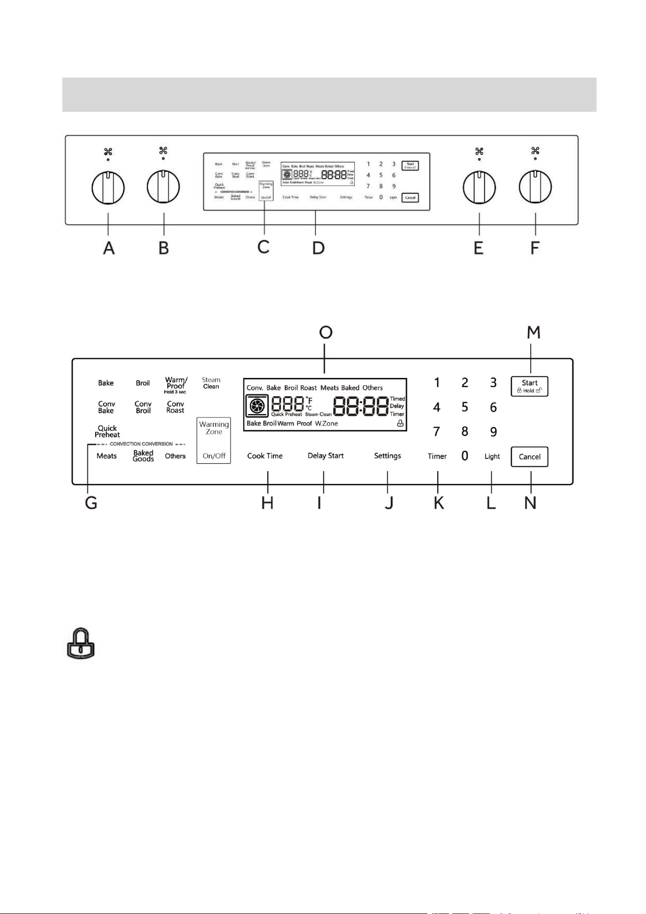
A Front Left Burner
B Rear Left Burner
C Center Burner (Warming Zone)
D Oven Touch Control
E Rear Right Burner
F Front Right Burner
G Convection Conversion
H Cook Time
I Delay Start
J Settings
K Timer
L Light
M Start/Control Lock (hold 3seconds)
N Cancel
O Display
Child lock icon – After holding “Start” button for 3 seconds, the icon will
appear on the display.
IMPORTANT: Clock must be set in order for the timed oven functions to work.
NOTE: In the event of a power failure, all settings including the clock time set will be lost.
When the power is returned, clock must be set again.
CONTROL PANEL
13
Oven Settings Guide
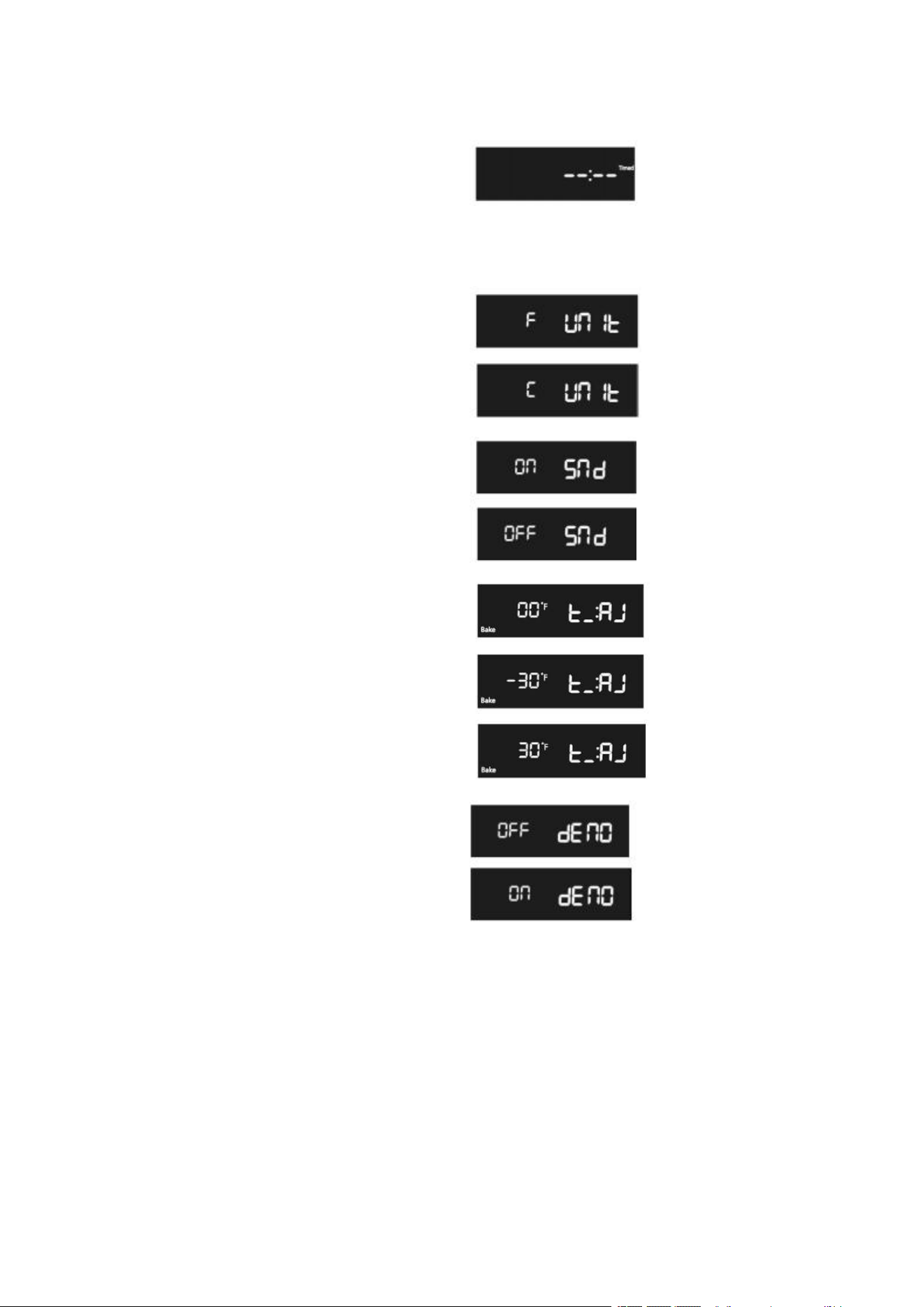
Clock
1. Press "Settings" repeatedly until the
display shows " --:-- Timed".
2. Press numbers to enter the time.
3. Press "Start" to save.
Selecting Fahrenheit or Celsius
1.Press "Settings" repeatedly until "Unit"
appears in the display.
2.Press "1" to select F(Fahrenheit)or (Celsius).
3.Press "Start" to save.
Sound
1. Press "Settings" repeatedly until "Snd"
appears in the display.
2. Press "1" to select On or Off.
3. Press "Start" to save.
Adjusting the Oven Temperature
1. Press "Settings" repeatedly until “t_AJ"
appears in the display.
2. Press "1" to select the mode you want to
adjust temperature.
3. Press "3" or "6" to select the temperature.
4. Press "Start" to save.
Demo mode
1. Press "Settings" repeatedly until "dEno"
appears in the display.
2. Press "1" to select On or Off.
3. Press "Start" to save.

14
Setting the Hour Mode
1. Press "Settings" repeatedly until “12h"
or"24h" appears in the display.
2. Press "1" to select "12h" or "24h".
3. Press "Start" to save.
Setting the SABBATH mode
1. Press "Settings" repeatedly until "SAbb"
appears in the display.
2. Press "1" to select On or Off.
3. Press "Start" to save.

15
The ceramic cooking area will glow red when a heating element is on. Some parts of the
cooktop may not glow red when an element is on. This is normal. The cooking area cycles
off and on, even when set to HI to keep the cooktop glass from overheating. It is normal for
the surface of ceramic glass to appear to change color when surface cooking areas are hot.
As the glass cools, it will return to its original color.
IMPORTANT: To avoid permanent damage from pitting or scratching and to maintain the
condition of the cooktop surface, clean the cooktop after each use. Ceramic glass cooktop
cleaner and a cooktop scraper are also recommended for stubborn soils. Do not use
abrasive cleaners, cleaning pads or harsh chemicals for cleaning. All of the items needed to
clean your ceramic glass cooktop are available at most grocery stores. See the “Range
Care” section for additional information.
• Make sure the bottoms of pots and pans are clean and dry before using them. Residue
and water can leave deposits when heated.
• Avoid storing jars or cans above the cooktop. Dropping a heavy or hard object onto the
cooktop could crack the cooktop.
• To avoid damage to the cooktop, do not leave a hot lid on the cooktop. As the cooktop
cools as air can become trapped between the lid and the cooktop, and the ceramic
glass could break when the lid is removed.
• For foods containing sugar in any form, clean up all spills as soon as possible. If sugary
spills are allowed to cool down, they can adhere to the cooktop and can cause pitting
and permanent marks.
• Allow the cooktop to cool down slightly.
• While wearing oven mitts, remove the spill using a scraper while the surface is still
warm.
• To avoid scratches, do not slide cookware or bakeware across the cooktop. Aluminum
or copper bottoms and rough finishes on cookware or bakeware could leave scratches
or marks on the cooktop.
• Do not cook popcorn in prepackaged aluminum containers on the cooktop. They could
leave aluminum marks that cannot be removed completely.
• To avoid damage to the cooktop do not allow objects that could melt such as plastic or
aluminum foil, to touch any part of the entire cooktop.
• To avoid damage to the cooktop, do not use the cooktop as a cutting board.
• To avoid damage to the cooktop, do not cook foods directly on the cooktop.
Prepare your cooktop before first use
1. If present, remove all packing and literature from the cooktop surface.
2. Clean your glass top. A thorough cleaning with a glass top cleaner is recommended.
3. Place a saucepan of water on each of the front burners and turn them on HI heat for at
least 30 minutes. Turn off the front burners.
4. Place a saucepan of water on each of the rear burners and turn them on HI heat for at
least 30 minutes. Turn off the rear burner.
COOKTOP USE

16
NOTES:
• This procedure evaporates any protective oils and humidity collected during the
manufacturing process, and enables the electronic control circuits to operate properly.
• There may be a slight odor during the first several uses; this is normal and will dissipate.
• The cooking surface will hold the heat and remain hot over 20 minutes after the
elements have been turned off.
HEATING ELEMENTS
NOTES:
• For fastest boiling with pots 10" (25.4 cm) and larger, use the Even-Heat™ (Triple-ring)
element with all elements set to “Hi.”
• For best low heat performance with pans 10" (25.4 cm) and larger, use the Dual-Size
element set to “Single Lo.”
• For best melting performance with small pans, use the Even-Heat™ element.
HOT SURFACE INDICATOR LIGHT
On ceramic glass cooktops the Hot Surface Indicator lights are located on the glass
cooktop.
The Hot Surface Indicator Lights will glow as long as any cooking area is too hot to touch,
even after the surface cooking area is turned off.
DUAL-RING COOKING ELEMENT
The Dual-Size Cooking Element offers the flexibility to use larger cookware.
• Single-size elements can be used in the same way as a regular element.
• The dual-size combines both the single and outer element and is recommended for
larger size cookware.
TRIPLE-RING ELEMENT
The Triple-ring Element offers flexibility because it features a wide range of setting.
• The High heat option can be used to boil small amounts of liquid quickly. To reduce the
power setting, turn the knob clockwise.
• The Melt setting is designed for delicate foods that require low heat, such as when
melting chocolate or holding sauces. Use cookware appropriate in size for the
triple-ring Element.
17
WARMING ZONE ELEMENT
WARNING
Food Poisoning Hazard
Do not let food sit in oven more than one hour before or after cooking.
Doing so can result in food poisoning or sickness.
• Use the Warming Zone element to keep cooked foods warm. One hour is the
recommended maximum time recommended to maintain food quality.
• Do not use the Warming Zone element to heat cold foods.
• The Warming Zone element can be used alone or when any of the other surface
cooking areas are being used.
• The Warming Zone element area will not glow red when cycling on. However, the hot
surface indicator will glow while the Warming Zone element is in use.
• Use only cookware recommended for cooktop use.
• Cover all foods with a lid or aluminum foil. When warming baked goods allow a small
opening in the cover for moisture to escape.
• Do not use plastic wrap to cover food because the plastic wrap may melt.
• Use pot holders to remove food.
RECOMMENDED COOKTOP HEATING ELEMENT SETTINGS
Heating elements do not require preheating.
A range of heating settings is listed in the following chart because the required
temperature depends on:
• Type and quality of pan
• Type, quantity and temperature of the food
• Element used and cook’s preferences
TYPE OF FOOD
HEAT SETTINGS RADIANT ELEMENTS
Energy regulator
Melting butter, chocolate
LO
Delicate sauce, rice, simmering sauces with
butter and egg yolk
LO to Medium
Cooking vegetables, fish broths, eggs -fried or
scrambled-, finishing cereals, pasta, milk,
pancakes, pudding, simmering meats,
steaming vegetables, pop corn, bacon, stewing
meet soup, sauteed vegetables, spaghetti
Medium
18
sauces
Braising meet, pan frying meet, fish, eggs, stir
frying, quickly brown or sear meats, hold rapid
boil
Medium to HI
Boiling water for vegetables, pasta
HI
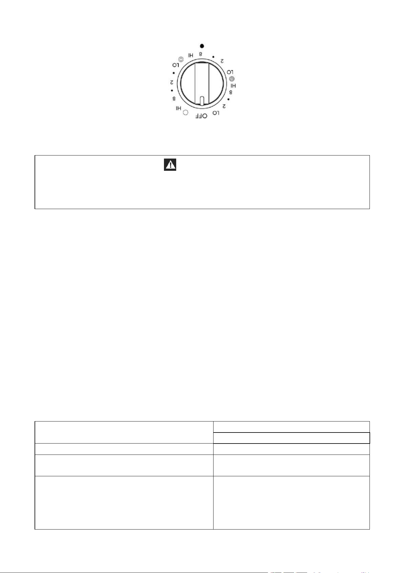
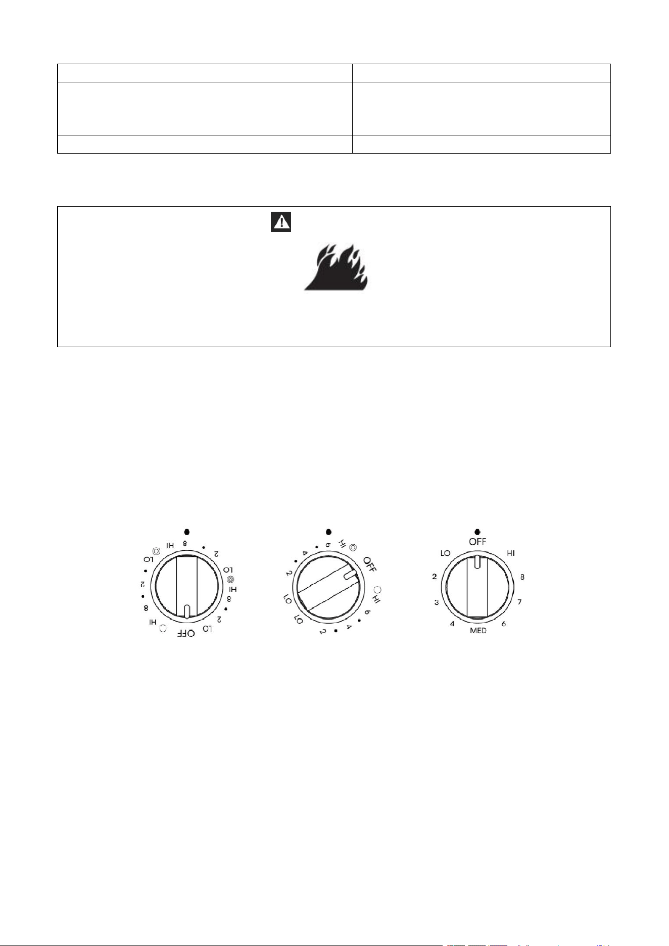
CONTROL KNOBS
WARNING
Fire Hazard
Turn off all controls when done cooking.
Failure to do so can result in death or fire.
The control knobs turn in either direction and from any position to the desired temperature
setting or to OFF.
NOTE:
Once the element is turned Off, the Hot Surface indicator light will remain illuminated until
the surface temperature of the element has cooled.
The placement of each knob corresponds to the placement of the heating element that it
controls.
To Turn On Any Heating Element:
• PUSH DOWN on the knob and TURN in either direction to desired heat setting.
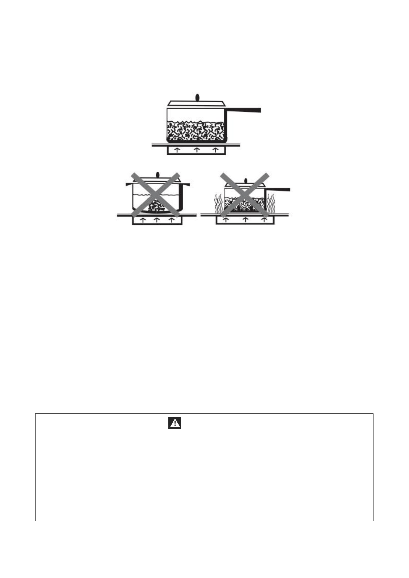
COOKWARE
The choice of pan directly affects the cooking performance (speed and uniformity).
For best results, select pans with the following features.
Flat Base
Use flat-bottomed cookware for best heat conduction and energy efficiency.
Cookware with rounded, warped, ribbed or dented bottoms could cause uneven heating
and poor cooking results.
• Determine flatness by placing the straight edge of a ruler across the bottom of the
cookware. While you rotate the ruler, no space or light should be visible between it and
the cookware.
19
• Cookware designed with slightly indented bottoms or small expansion channels can be
used.
Match Pan Diameter to Element
The base of the pan should cover or match the diameter of the element being used.
BALANCED PAN
UNBALANCED PAN
COOKWARE CHARACTERISTICS
• Aluminum: heats and cools quickly. Frying, braising, roasting. May leave metal
markings on glass.
• Cast Iron: on a glass cooktop heats and cools slowly, but retains heat and cooks evenly.
• Copper: tin heats and cools quickly. Best used for gourmet cooking, wine sauces, egg
dishes.
• Enamel ware: response depends on base metal. Not recommended. Imperfections in
enamel may scratch cooktop.
• Glass Ceramic: heats and cools slowly. Not recommended. Heats too slowly.
Imperfections in enamel may scratch cooktop.
• Stainless Steel: heats and cools moderately. Soups, sauces, vegetables, and general
cooking.
HOME CANNING
CAUTION
Food Poisoning Hazard
Safe canning requires that harmful micro organisms are destroyed and that the jars are
sealed completely. When canning foods in a water-bath canner, a gentle but steady boil
must be maintained for the required time. When canning foods in a pressure canner, the
pressure must be maintained for the required time.
After you have adjusted the controls, it is very important to make sure the prescribed boil
or pressure levels are maintained for the required time.
Failure to do so can result in food poisoning or sickness.

20
Canning can be performed on a glass smooth top cooking surface or traditional coil
element cooktop.
• When canning for long periods, alternate the use of surface cooking areas or elements
between batches. This allows time for the most recently used areas to cool.
• Center the canner on the largest surface cooking area or element. On electric cooktops,
canners should not extend more than ½" (1.3 cm) beyond the surface cooking area or
element.
• Do not place canner on 2 surface cooking areas or elements at the same time.
• On ceramic glass models, use only flat-bottomed canners to avoid damage to the
cooktop and elements.
For more information, contact your local agricultural extension office, or refer to published
home canning guides. Companies that manufacture home canning products can also offer
assistance.

21
This multi-function oven combines the functions of traditional oven modes with the
functions of modern, fan-assisted convection modes in a single oven. Use the Cooking
Mode control, located on the control panel, to select the oven mode.
IMPORTANT:
During any cycle, the heating elements will turn off when the oven door is opened, and
stay off until the door is closed. To maintain oven temperature, limit door openings during
cooking.
BEFORE USING THE OVEN FOR THE FIRST TIME
1. Close the oven door.
2. Press Bake.
3. Press 500°F (260°C) on the number keypad.
4. Press Start.
NOTE: Allow the oven to operate for 30 minutes with the door closed and no food in
the cavity.
5. ool.
NOTE: Any odor that may be detected during this initial use is due to the evaporation
of substances used to protect the oven during storage.
GENERAL
IMPORTANT: Do not place anything, including dishes, foil and oven trays, on the bottom of
the oven when it is in operation to avoid damaging the enamel.
1. Place bakeware with food on the rack provided with the oven.
2. Close the oven door.
NOTE: The oven cannot be set with the door open.
3. Press the desired oven mode ie. BAKE.
4. Set the oven to the desired temperature.
5. Press START.
OVEN RACKS
The oven racks can be placed in any of the six height positions within the oven.
Oven racks have a stop to keep them from being unintentionally withdrawn fully.
PREHEATING
When beginning a Bake, Convection Bake or Convection Roast cycle, the oven will begin
preheating after Start is pressed. The oven will take approximately 12 to 15 minutes to reach
350°F (177°C) with all of the oven racks provided with your oven inside the oven cavity.
Higher temperatures will take longer to preheat. The preheat cycle rapidly increases the
oven temperature. The actual oven temperature will go above your set temperature to
offset the heat lost when you open the oven door to place the food on the rack. This
ensures that cooking will begin at the proper temperature. Do not open the door while the
OVEN USE

22
oven is preheating. When the oven has heated to the set temperature, a tone will sound.
You can then open the door and place food in the oven.
OVEN MODES
BAKE
Baking is cooking with heated air. Both upper and lower elements in the oven are used to
heat the air but no fan is used to circulate the heat.
Follow the recipe or convenience food directions for baking temperature, time and rack
position. Baking time will vary with the temperature of ingredients and the size, shape and
finish of the baking utensil.
The temperature can be set from 170°F (77°C) to 550°F (288°C).
General Guidelines
• For best results, bake food on a single rack with at least 1" - 1½" (2.5 - 4 cm) space
between bakeware and oven walls.
• Use one rack when selecting the bake mode.
• Check for doneness at the minimum time.
• Use metal bake ware (with or without a non stick finish), heatproof glass, glass ceramic,
pottery or other utensils suitable for the oven.
• When using heatproof glass, reduce temperature by 25°F (15°C) from recommended
temperature.
• Use baking sheets with or without sides or jelly roll pans.
• Dark metal pans or nonstick coatings will cook faster with more browning. Insulated
bake ware will slightly lengthen the cooking time for most foods.
• Do not use aluminum foil or disposable aluminum trays to line any part of the oven. Foil
is an excellent heat insulator and heat will be trapped beneath it. This will alter the
cooking performance and can damage the finish of the oven.
• Avoid using the opened door as a shelf to place pans.
• See Troubleshooting for tips to Solving Baking Problems.
Bake Chart
FOOD ITEM
RACK
POSITION
TEMP. °F (°C)
(PREHEATED OVEN)
TIME (MIN)
Cake
Cupcakes
Bundt Cake
Angel Food
2
1
1
350 (175)
350 (175)
350 (175)
19-22
40-45
35-39
Pie
2 crust, fresh, 9"
2 crust, frozen fruit, 9"
2
2
375-400 (190-205)
375 (190)
45-50
68-78
Cookies
Sugar
Chocolate Chip
Brownies
2
2
2
350-375 (175-190)
350-375 (175-190)
350 (175)
8-10
8-13
29-36
Breads
Yeast bread loaf, 9x5
Yeast rolls
2
2
2
375 (190)
375-400 (190-205)
375-400 (190-205)
18-22
12-15
7-9

23
Biscuits
Muffins
2
425 (220)
15-19
Pizza
Frozen
Fresh
2
2
400-450 (205-235)
475 (246)
23-26
15-18
To Bake:
1. Close the oven door.
NOTE: The oven controls cannot be set if the oven door is open.
2. Press BAKE. “BAKE” will appear in the display, and 350°F (177°C) will be displayed.
3. Press START, if you wish to bake at 350°F (177°C).
OR
Enter the desired temperature by pressing the number keypad, and then press START.
The temperature can be set from 170°F (77°C) to 550°F (288°C).
NOTES:
• The temperature may be changed at any time during cooking. Press CANCEL to clear
the settings. Select oven mode, then enter the desired temperature by pressing the
number keypad, and then press START.
• After selecting an Oven Mode and Temperature, you have the option to set a Cook
Time before pressing START.
4. Once START has been pressed, the oven will begin to preheat. When the oven has
reached the set temperature, a tone will sound.
5. Place the food in the oven and close the oven door when preheat is complete.
6. Press CANCEL when finished cooking, and remove food from the oven.
BROIL
Broiling uses direct radiant heat to cook food. The lower the temperature, the slower the
cooking. Thicker cuts and unevenly shaped pieces of meat, fish and poultry may cook
better at lower broiling temperatures.
NOTES:
• Before broiling, position rack according to the Broiling Chart.
• For best results, use a two-piece broiler pan with a grid (not provided). It is designed to
drain juices which helps to avoid spatter and smoke.
• For proper draining, do not cover the grid with foil. The bottom of the pan may be lined
with aluminum foil for easier cleaning.
• Trim excess fat to reduce spattering. Slit the remaining fat on the edges to avoid
curling.
• Select HI Broil 550°F (288°C) for most broiling. Select LO Broil 450°F (232°C) for
low-temperature broiling for foods that take longer to cook, such as poultry, to avoid
over browning.
• Pull out oven rack to stop position before turning or removing food. Use tongs to turn
food to avoid the loss of juices. Very thin cuts of fish, poultry or meat may not need to
be turned.
• After broiling, remove the pan from the oven when removing the food. Drippings will
bake on the pan if left in the heated oven, making cleaning more difficult.
24
• Position food on grid in the broiler pan, then place it in the center of the oven rack.
Close the oven door and set the control.
To Broil:
The temperature can be set from 450°F (232°C) to 550°F (288°C).
1. Place the food in the oven, preheating is not necessary.
2. Close the oven door.
3. Press BROIL. “BROIL”and “550ºF” (288ºC) will be displayed.
4. Press START, if you wish to broil at 550°F (288°C).
OR
Enter the desired temperature by pressing the number keypad, and then press START.
The temperature can be set from 450°F (232°C) to 550°F (288°C).
NOTES:
• The temperature can be changed at any time during cooking. Press CANCEL to
clear the settings. Select oven mode, then enter the desired temperature by
pressing the number keypad, and then press START.
• After selecting an Oven Mode and Temperature, you have the option to set a Cook
Time before pressing START.
5. BROIL will appear in the display after Start is pressed.
6. When cooking is finished, press CANCEL, and then remove food from the oven.
WARM/PROOF
The Warm mode keeps hot, cooked foods at serving temperature.
The Proof mode prepares dough for baking by activating the yeast. Follow the recipe
directions as a guide.
WARNING
Food Poisoning Hazard
Do not let food sit in oven more than one hour before or after cooking.
Doing so can result in food poisoning or sickness.
IMPORTANT: Food must be at serving temperature before placing it in the warmed oven.
Food may be held up to 1 hour; however, breads and casseroles may become too dry if left
in the oven during the Warm function. For best results, cover food.
Warm
1. Press WARM/PROOF, and then press WARM on the menu screen. “WARM” 140°F (60°C)
will be displayed.
2. Press START, if you wish to Warm food at 140°F (60°C).
OR
25
Enter the desired temperature by pressing the number keypad, and then press START.
The temperature can be set from 140°F (60°C) to 210°F (99°C).
3. “WARM” will appear in the display, once Start is pressed.
NOTE: After selecting an Oven Mode and Temperature, you have the option to set a
Cook Time before pressing START.
4. Place food in the oven and close the door.
5. Press CANCEL when finished, and remove food from the oven.
Proof
Before proofing, place the dough in a lightly greased bowl and cover loosely with wax
paper, coated with shortening.
1. Place on second rack from the bottom and close the oven door.
2. Press WARM/PROOF, and then hold for 3 seconds. “PROOF” and 100°F (38°C) will be
displayed.
3. Press START, if you wish to Proof dough at 100°F (38°C).
OR
Enter the desired temperature by pressing the number keypad, and then press
START.The temperature can be set from 80°F (27°C) to 120°F (49°C).
4. “PROOF” will appear in the display, once Start is pressed.
NOTE: After selecting an Oven Mode and Temperature, you have the option to set a
Cook Time before pressing START.
5. Let the dough rise until nearly doubled in size, checking after 20-25 minutes. Proofing
time may vary depending on dough type and quantity.
6. Press CANCEL when finished.
7. Before second proofing, shape the dough, place it in baking pan(s) and cover loosely with
plastic wrap, coated with cooking spray. Follow the same placement and control steps
above. Before baking, remove the plastic wrap.
CONVECTION MODES
During convection cooking, the fan provides hot air circulation throughout the oven. The
movement of heated air around the food can help to speed up cooking by penetrating the
cooler outer surfaces. Food cooks more evenly, browning and crisping outer surfaces while
sealing moisture inside.
When the oven is set to the Convection function, the ring element, bake and broil elements,
and the fan operate to heat the oven cavity. If the oven door is opened during convection
cooking or preheating, the fan turns off immediately and the element(s) will turn off after
30 seconds. Once the door is closed, the element(s) will automatically turn on.
26
CONVECTION FAN
The convection fan operates during any convection mode. When the oven is operating in
convection mode, the fan will turn off automatically when the door is opened. The
convection fan may run in non-convection modes during the preheat time.
CONVECTION BAKE
• Use Convection Bake for single or multiple rack baking. Reduce standard recipe baking
temperature by 25°F (15°C).
• For best results, foods should be cooked uncovered, in low-sided pans to take
advantage of the forced air circulation. Use shiny aluminum pans for best results unless
otherwise specified.
• Heatproof glass or ceramic can be used. Reduce temperature by another 25°F (15°C)
when using heatproof glass dishes for a total reduction of 50°F (30°C).
• Dark metal pans may be used. Note that food may brown faster when using dark metal
bake ware.
• The number of racks used is determined by the height of the food to be cooked.
• Baked items, for the most part, cook extremely well in convection. Don’t try to convert
recipes such as custards, quiches, pumpkin pie, or cheesecakes, which do not benefit
from the convection-heating process. Use the regular Bake mode for these foods.
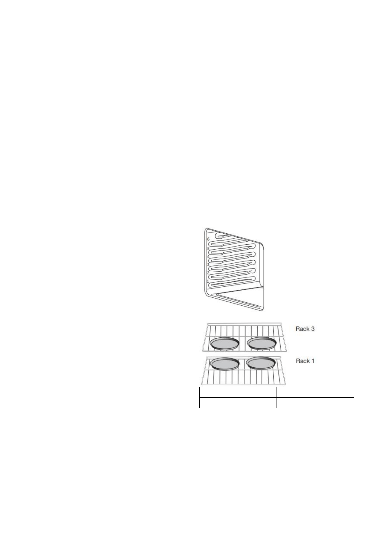
• Multiple rack cooking for oven meals is
done on rack positions 1, 2, 3 , 4 and 5. All
five positions can be used for cookies,
biscuits and appetizers.
- 2 Rack baking: Use positions 1 and 3.
- 3 rack baking: Use positions 2, 3 and 4
or 1, 3 and 5.
• When baking four cake layers at the
same time, stagger pans so that one pan
is not directly above another. For best
results, place cakes on front of upper
rack and back of lower rack. Allow 1" -
1½" (2.5 - 4 cm) air space around pans.
Rack 3
Rack 1
FOODS RECOMMENDED FOR CONVECTION BAKE MODE:
Appetizers Biscuits Coffee Cakes
Cookies (2 to 4 racks) Yeast Breads
Cream Puffs
Popovers
Casseroles and One-Dish Entreés
Oven Meals (rack positions 1, 2, 3)
Air Leavened Foods (Soufflés, Meringue, Meringue-Topped Desserts, Angel Food Cakes,
Chiffon Cakes)

27
Temperatures have been reduced in this chart.
FOOD ITEM
RACK
POSITION
TEMP. °F (°C)
(PREHEATED OVEN)
TIME (MIN)
Cake
Cupcakes
Bundt Cake
Angel Food
2
1
1
350 (175)
350 (175)
350 (175)
19-22
40-45
35-39
Pie
2 crust, fresh, 9"
2 crust, frozen fruit, 9"
2
2
375-400 (190-205)
375 (190)
45-50
68-78
Cookies
Sugar
Chocolate Chip
Brownies
2
2
2
350-375 (175-190)
350-375 (175-190)
350 (175)
8-10
8-13
29-36
Breads
Yeast bread loaf, 9x5
Yeast rolls
Biscuits
Muffins
2
2
2
2
375 (190)
375-400 (190-205)
375-400 (190-205)
425 (220)
18-22
12-15
7-9
15-19
Pizza
Frozen
Fresh
2
2
400-450 (205-235)
475 (246)
23-26
15-18
To Set Convection Bake:
1. Press Convection BAKE once. 325°F (162°C) will be displayed.
2. Press START If you wish to convection bake at 325°F (162°C).
OR
Enter the desired temperature by pressing the number keypad, and then press START.
The temperature can be set from 170°F (77°C) to 500°F(260°C).
NOTES:
• To change the set temperature press CANCEL. Press the number keypad to enter
the desired temperature, and then press START.
• After selecting an Oven Mode and Temperature, you have the option to set a Cook
Time before pressing START.
3. The oven will begin preheating once Start is pressed. A tone will sound when the oven is
at the set temperature.
4. Place the food in the oven and close the oven door when preheat is completed.
5. Press CANCEL when finished, and then remove food from the oven.

28
CONVECTION BROIL
General Guidelines
• Place rack in the required position needed before turning on the oven.
• Use Convection Broil mode with the oven door closed.
• When convection broiling, enter your normal broiling temperature.
• Do not preheat oven.
• Use the 2-piece broil pan.
• Turn meats once halfway through the cooking time. See the Convection Broil chart.
• Thicker cuts and unevenly shaped pieces of meat, fish and poultry may cook better at
lower broiling temperatures.
FOOD AND THICKNESS
RACK
POSITION
BROIL
SETTING
°F (°C)
INTERN
AL
TEMP. °
F
(°C)
TIME
SIDE 1
(MIN.)
*
TIME
SIDE 2
(MIN.)
*
Beef
Steak (1½" or more)
Medium rare
Medium
Well
Hamburgers (more than
1")
Medium
Well
4
4
4
4
4
450 (232)
450 (232)
450 (232)
550
(288)
550
(288)
160 (71)
170 (77)
145 (65)
160 (71)
170 (77)
8-11
11-13
9-12
11-13
18-20
5-7
8-10
8-10
10-12
16-17
Poultry
Chicken Quarters
Chicken Halves
Chicken Breasts
4
3
4
450 (232)
450 (232)
450 (232)
180 (82)
180 (82)
170 (77)
16-18
25-27
13-15
10-13
15-18
9-13
Pork
Pork Chops (1¼" or more)
Sausage - fresh
4
4
450 (232)
450 (232)
160 (71)
160 (71)
12-14
4-6
11-13
3-5
To Set Convection Broil:
1. Place the food in the oven and close the oven door.
2. Press Convection BROIL once. 450°F (232°C) will be displayed.
3. Press START, if you wish to broil at 450°F (232°C).
OR
Enter the desired temperature by pressing the number keypad, and then press START.
The temperature can be set from 170°F (77°C) to 550°F (288°C).
NOTES:
• To change the set temperature press CANCEL. Press the number keypad to enter
the desired temperature, and then press START.
• After selecting an Oven Mode and Temperature, you have the option to set a Cook
Time before pressing START.
4. “Convect Broil” will be displayed, once Start is pressed.
5. Press CANCEL when cooking is finished, and then remove food from the oven.

29
CONVECTION ROAST
When Convection roasting, enter your normal roasting temperature. The roasting time
should be 15-30% less than in conventional cooking. It is not necessary to preheat the oven
for convection roast.
General Guidelines
• Do not preheat for Convection Roast.
• Roast in a low-sided, uncovered pan.
• When roasting whole chickens or turkey, tuck wings behind back and loosely tie legs
with kitchen string.
• Use the 2-piece broil pan for roasting uncovered.
• Use the probe or a meat thermometer to determine the internal doneness.
• Double-check the internal temperature of meat or poultry by inserting meat
thermometer into another position.
• Large poultry may need to be covered with foil (and pan roasted) during a portion of
the roasting time to prevent over-browning.
• The minimum safe temperature for stuffing in poultry is 165°F (75°C).
• After removing the food from the oven, cover loosely with foil for 10 to 15 minutes
before carving if necessary to increase the final foodstuff temperature by 5° to 10°F (3°
to 6° C).
MEATS
WEIGHT
(lb)
OVEN TEMP.
°F (°C)
RACK
POSITION
TIME
(min. per
lb)
INTERNAL
TEMP. °F (°C)
Beef
Rib Roast
4-6
325 (160)
2
16-20
18-22
145 (63)
medium rare
160 (71)
medium
Rib Eye Roast,
(boneless)
4-6
325 (160)
2
16-20
18-22
145 (63)
medium rare
160 (71)
medium
Rump, Eye, Tip,
Sirloin (boneless)
3-6
325 (160)
2
16-20
18-22
145 (63)
medium rare
160 (71)
medium
Tenderloin Roast
2-3
400 (205)
2
15-20
145 (63)
medium rare
Pork
Loin Roast (boneless
or bone-in)
5-8
350 (175)
2
16-20
160 (71)
medium
Shoulder
3-6
350 (175)
2
20-25
160 (71)
medium
Poultry
Chicken whole
3-4
375 (190)
2
18-21
180 (82)

30
Turkey, not stuffed
12-15
325 (160)
1
10-14
180 (82)
Turkey, not stuffed
16-20
325 (160)
1
9-11
180 (82)
Turkey, not stuffed
21-25
325 (160)
1
6-10
180 (82)
Turkey Breast
3-8
325 (160)
1
15-20
170 (77)
Comish Hen
1-1½
350 (175)
2
45-75 total
180 (82)
Lamb
Half Leg
3-4
325 (160)
2
22-27
28-33
160 (71)
medium
170 (77) well
Whole Leg
6-8
325 (160)
1
22-27
28-33
160 (71)
medium
170 (77) well
To Set Convection Roast:
1. Place the food in the oven and close the oven door.
2. Press CONVECTION ROAST once. 325°F (163°C) will be displayed.
3. Press START, if you wish to convection roast at 325°F (163°C).
OR
Enter the desired temperature by pressing the number keypad, and then press START.
The temperature can be set from 170°F (77°C) to 550°F (288°C).
NOTES:
• To change the set temperature during cooking, press CANCEL. Press the number
keypad to enter the desired temperature, and then press START.
• After selecting an Oven Mode and Temperature, you have the option to set a Cook
Time before pressing START.
4. Press START. After pressing START, the oven will display ”CONVECT ROAST” while
cooking.
5. Press CANCEL when finished, and then remove food from the oven.
CONVECTION CONVERSION
When using a Convection Recipe, enter your normal cooking temperature and time. The
Convection Conversion mode will adjust the temperature and time for perfect cooking
results.
IMPORTANT:
• The oven door must be closed before selecting a Convection Conversion oven mode.
• Setting Cook Time is required for a Convection Conversion oven mode.
BAKED GOODS
1. Press BAKED GOODS among the Convection Conversion controls.
2. Set the oven temperature.
NOTE: The temperature can be set from 170°F (77°C) to 500°F (260°C).
3. Press START. “Conv. Baked” will appear in the display.
4. Press the number keypad to enter the desired cook time. “Press START” will appear in the
display.

31
5. Press START. The oven begins to preheat. Once the set temperature has been reached, a
tone will sound.
6. At the end of the set Cook Time the oven will turn off automatically, the end of cycle
tone will sound and “End” will appear in the display.
MEATS
IMPORTANT: It is not necessary to preheat the oven for the convection conversion MEAT
option.
1. Press MEATS among the Convection Conversion controls.
2. Set the oven temperature.
NOTE: The temperature can be set from 170°F (77°C) to 500°F (260°C).
3. Press START. “Conv. Meats” will appear in the display.
4. Press the number keypad to enter the desired cook time. “Press START” will appear in the
display.
5. At the end of the set Cook Time the oven will turn off automatically, the end of cycle
tone will sound and “End” will appear in the display.
OTHER FOODS
1. Press OTHER FOODS among the Convection Conversion controls.
2. Set the oven temperature.
NOTE: The temperature can be set from 170°F (77°C) to 500°F (260°C).
3. Press START. “Conv. Others” will appear in the display.
4. Press the number keypad to enter the desired cook time. “Press START” will appear in the
display.
5. Once START has been pressed, the oven begins to preheat. Once the set temperature
has been reached, a tone will sound.
6. At the end of the set Cook Time the oven will turn off automatically, the end of cycle
tone will sound and will appear in the display.

32
CLEANING
IMPORTANT: Before cleaning, make sure all controls are turned off, and the oven and
cooktop are cool. Always follow label instructions on cleaning products. It is recommended
that you first use soap, water and a soft cloth or sponge unless otherwise noted. Do not use
abrasive cleaning products.
EXTERIOR PORCELAIN ENAMEL SURFACES
Food spills containing acids, such as vinegar and tomato, should be cleaned as soon as the
entire appliance is cool. These spills may affect the finish.
Cleaning Method:
Glass cleaner, mild liquid cleaner or nonabrasive scrubbing pad: Gently clean around the
model and serial number plate because scrubbing may remove numbers.
EXTERIOR STAINLESS STEEL
NOTE: Do not use soap-filled scouring pads, abrasive cleaners, cooktop polishing cream,
steel-wool pads, gritty washcloths or some paper towels. Damage may occur, even with
one-time or limited use.
Rub in direction of grain to avoid damaging.
Cleaning Methods:
Liquid detergent or all-purpose cleaner: Rinse well with clean water and dry with soft,
lint-free cloth.
Stainless Steel Cleaner and Polish
Vinegar for hard water spots
OVEN DOOR EXTERIOR
Cleaning Method:
Glass cleaner and paper towels or nonabrasive plastic scrubbing pad: Apply glass cleaner to
soft cloth or sponge, not directly on panel.
CERAMIC GLASS COOKTOP
IMPORTANT: To avoid damaging the cooktop, do not use steel wool, abrasive powder
cleansers, chlorine bleach, rust remover or ammonia. Ceramic cooktop cleaning materials:
cooktop cleaner, cooktop scraper and cooktop cleaning pads are available at most grocery
stores.
RANGE CARE

33
To Clean the Ceramic Glass Cooktop:
1. Remove food/residue with a cooktop scraper.
• For best results, use the cooktop scraper while the cooktop is still warm, but not
hot to the touch.
• It is recommended to wear an oven mitt while scraping the warm cooktop.
• Hold the cooktop scraper at approximately a 45° angle against the glass surface
and scrape the residue. It will be necessary to apply pressure in order to remove
the residue.
• Allow the cooktop to cool down completely before proceeding to Step 2.
2. Apply a few dime-sized drops of cooktop cleaner to the affected areas.
• Rub cooktop cleaner onto the cooktop surface with a nylon or similar cooktop
cleaning pad. Some pressure is needed to remove stubborn stains.
• Allow the cleaner to dry to a white haze before proceeding to Step 3.
3. Polish with a clean, dry cloth or a clean, dry paper towel.
SMUDGES FROM ALUMINUM BOTTOMED PANS
Cleaning Method:
A cloth dampened in vinegar.
COOKTOP CONTROL KNOBS
• Pull knobs straight out from the control panel to remove.
• When replacing knobs, make sure knobs are turned to the Off position.
Cleaning Method:
Soap and water or dishwasher:
NOTE: Do not use steel wool, abrasive cleansers or oven cleaner. Do not soak knobs.
CONTROL PANEL
Cleaning Method:
Glass cleaner and soft cloth or sponge: Apply glass cleaner to soft cloth or sponge, not
directly on panel.
NOTE: Do not use abrasive cleaners, steel-wool pads, gritty washcloths or some paper
towels. Damage may occur.
OVEN CAVITY
Food spills should be cleaned when oven cools. At high temperatures, foods react with
porcelain, so staining, etching, pitting or faint white spots can result.
Cleaning Method:
Mild detergent and warm water.
NOTE: Do not use oven cleaners.

34
OVEN RACKS
Cleaning Method:
Steel-wool pad
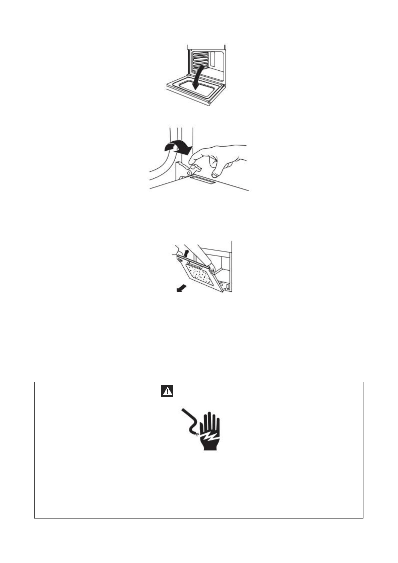
To Steam-Clean
1. Make sure the oven is "OFF" and everything is removed from inside of the oven.
2. Prepare steam cleaning solution of 85% distilled water, 10% white vinegar & 5%
dishwashing liquid (approximately 10 oz) and place into a spray bottle.
3. Open the oven door and spray steam cleaning solution evenly around the interior of the
oven cavity and on the interior glass surface of the oven door.
4. Pour ¼ cup of distilled/filtered water in the sealed bottom of the oven cavity.
5.Close the oven door. Then press the Steam Clean button, and the Steam Clean icon will
display on the screen along with a preset time of 20 minutes and then also the word Timed
next to it.
NOTE: You are able to adjust the time for a longer Steam Clean cycle if you choose to by
pressing the Cook Time button and this shows up on the display screen -- : -- then press
the numbers for the desired time you want (FYI it's in minutes and hours) and then press
the Start button twice and it will Start the steam clean cycle. To Cancel: Simply press the
Cancel button.
NOTE: Oven door will not lock in the Steam Clean cycle, but if you open the door the cycle
will pause until you reclose the door. (One fan will stay on but the cycle has paused).
6. When the Steam Clean cycle is done the oven will beep a few times and "End" will appear
on the display screen. To remove the word End simply press the Cancel button and then
the time will reappear on the display screen.
7. The fan will run until the oven has cooled down some but the oven will still be hot to the
touch.
8. Once the oven has completely cooled down, then open the oven door and wipe the oven
down with a damp cloth.
OVEN DOOR REMOVAL
For normal oven use, there is no need to remove the oven door. However, should it
become necessary to remove the door, follow the instructions in this section.
IMPORTANT:
• Make sure oven is cool and power to the oven has been turned off before removing the
door.
• The oven door is heavy and fragile, and the door front is glass. To avoid oven door glass
breakage, use both hands, and grasp only the sides of the oven door to remove.
• Be sure that both levers are securely in place before removing the door.
• Do not force door open or closed.
To remove the oven door:
1. Open the oven door completely.
35
2. Lift up the hinge latch on each side.
3. Close the oven door as far as it will shut.
4. While grasping both outside edges of the oven door, lift up on the door.
5. Continue to push the top of the door closed, while pulling the bottom of the door out of
the hinge receivers in the door frame.
To replace the oven door:
1. Insert both hanger arms into the hinge receivers in the door frame.
2. Slowly open the oven door, and you will feel the door set into place.
3. Move the hinge latches back into the locked position.
4. Check that the door opens and closes freely. If it does not, repeat the door removal and
replacement procedures.
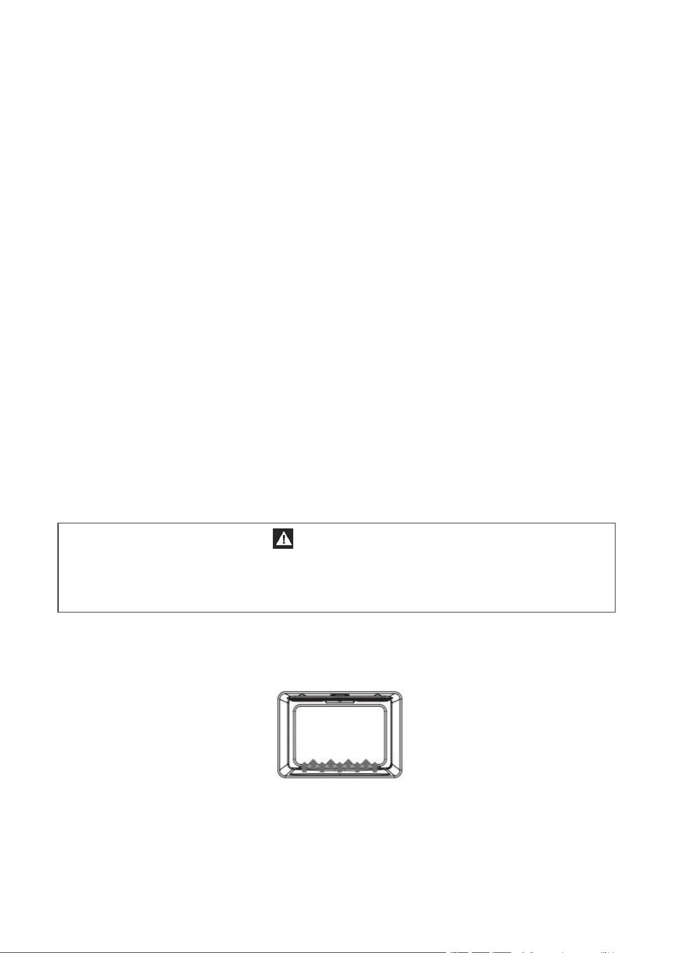
REPLACING AN OVEN LIGHT
WARNING
Electrical Shock Hazard
Make sure the oven and lights are cool and power to the oven has been turned off before
replacing the light bulb(s).
The lenses must be in place when using the oven. The lenses serve to protect the light bulb
from breaking.
The lenses are made of glass. Handle carefully to avoid breakage.
36
Failure to do so could result in death, electric shock, cuts or burns.
The oven light is a standard 25 watt (G9) appliance bulb.
IMPORTANT: Before replacing the bulb, make sure the oven is cool and the controls are
turned off.
WARNING:
1. Make sure the oven and lights are cool and power to the oven has been turned off before
replacing the light bulb(s).
2. The lenses must be in place when using the oven. The lenses serve to protect the light
bulb from breaking.
3. The lenses are made of glass. Handle carefully to avoid breakage.
4. Failure to do so could result in death, electric shock, cuts or burns.
REPLACING AN OVEN LIGHT
The oven light is a standard 25-watt (G9) appliance bulb.
IMPORTANT: Before replacing the bulb, make sure the oven is cool and the controls are
turned off.
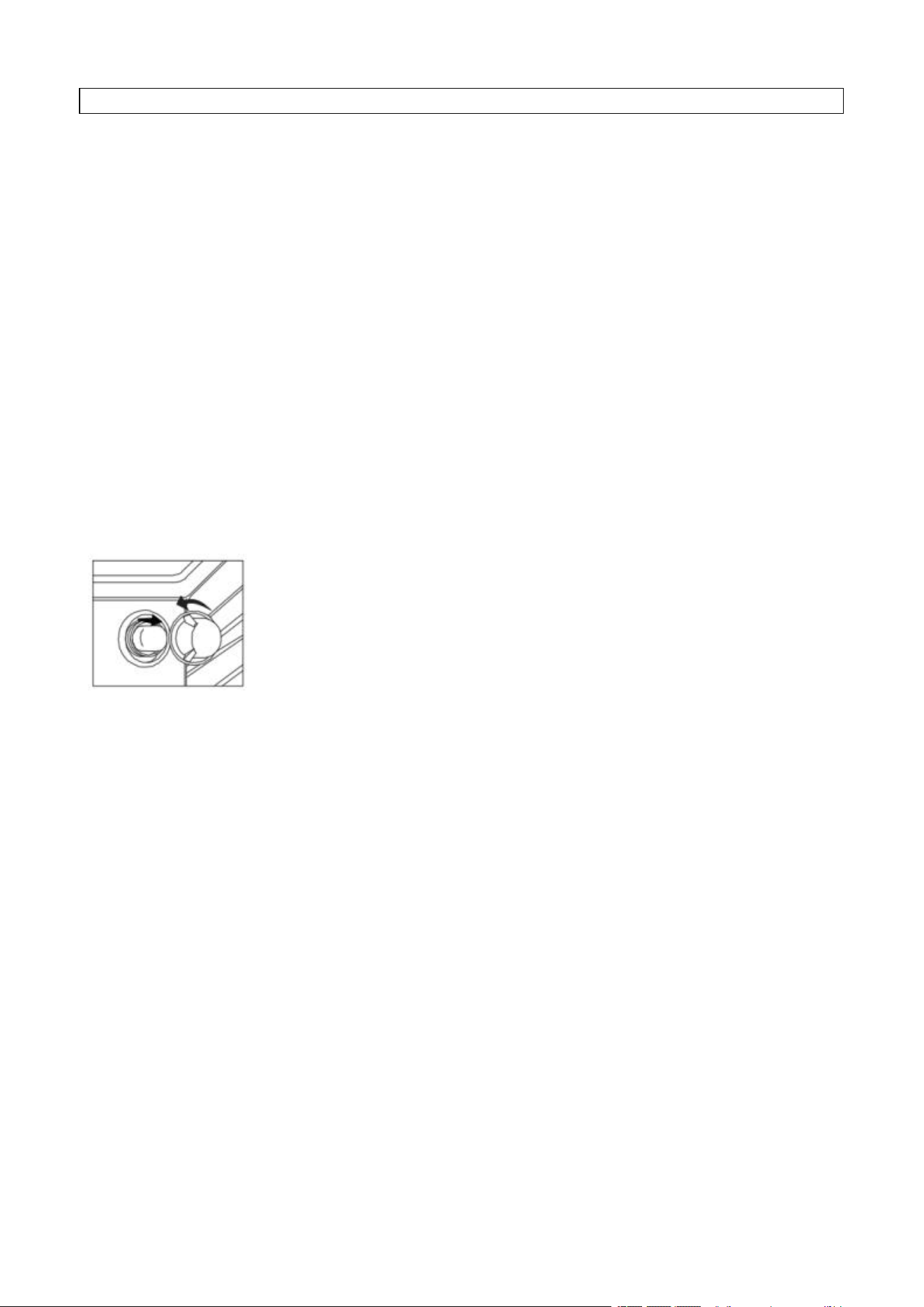
1. Disconnect the power.
2. Remove the bulb cover by turning it anti-clockwise.
3. Remove the burned-out bulb from the socket.
NOTE: To avoid damage or decreasing the life of the new bulb, do not touch the bulb
with bare fingers. Wear gloves or use a tissue when replacing the light bulb.
4. Replace the bulb, and then replace the bulb cover.
5. Reconnect the power.
37
BAKING AND ROASTING PROBLEMS
With any oven setting poor results can occur for many reasons other than a malfunction of
the oven. Check the chart below for causes of the most common problems. Since the size,
shape and material of baking utensils directly affect the baking results, the best solution
may be to replace old baking utensils that have darkened and warped with age and use.
BAKING PROBLEM
CAUSE
Food browns unevenly
• Oven not preheated
• Aluminum foil on oven rack or oven bottom
• Baking utensil too large for recipe
• Pans touching each other or oven walls
Food too brown on bottom
• Oven not preheated
• Using glass, dull or darkened metal pans
• Incorrect rack position
• Pans touching each other or oven walls
Food is dry or has shrunk
excessively
• Oven temperature too high
• Baking time too long
• Oven door opened frequently
• Pan size too large
Food is baking or roasting too
slowly
• Oven temperature too low
• Oven not preheated
• Oven door opened frequently
• Tightly sealed with aluminum foil
• Pan size too small
Piecrusts do not brown on
bottom or crust is soggy
• Baking time not long enough
• Using shiny steel pans
• Incorrect rack position
• Oven temperature is too low
Cakes pale, flat and may not be
done inside
• Oven temperature too low
• Incorrect baking time
• Cake tested too soon
• Oven door opened too often
• Pan size may be too large
Cakes high in middle with crack
on top
• Oven temperature too high
• Baking time too long
• Pans touching each other or oven walls
• Incorrect rack position
• Pan size too small
Piecrust edges too brown
• Oven temperature too high
• Edges of crust too thin
COOKTOP
TROUBLESHOOTING
38
PROBLEM
POSSIBLE CAUSE
SOLUTION
Heating elements and
controls do not work.
Fuse is blown or circuit
breaker is tripped.
No electricity to the
cooktop.
Replace the fuse or reset the
circuit breaker. If the problem
continues, call an electrician.
Have electrician check your
power supply.
Heating elements do
not heat properly.
Improper cookware is being
used.
Select proper cookware. See
“Cookware.”
If the problem continues, call for
service.
Heating elements cycle
off even when elements
are turned to their
highest settings.
Heating element
temperature limiters are
temporarily shutting off the
elements due to exceeding
the maximum allowable
temperature.
This is a normal operating
condition, especially during rapid
heat-up operations.
The element will cycle back on
automatically after it has cooled
sufficiently.
Glass ceramic surface is
see through or appears
to be red in color.
Under direct or bright
lighting, you will sometimes
be able to see through the
glass and into the chassis
due to its transparent
quality. You may also notice
a red tint under these
conditions
These are normal properties of
black ceramic glass panels.
OVEN
PROBLEM
POSSIBLE CAUSE
SOLUTION
Oven is not heating
No power to the oven
Replace the fuse or reset the
circuit breaker. If the problem
continues, call an electrician.
Oven control not turned on
Make sure the oven temperature
has been selected.
Oven door is not closed.
Close the oven door. The heating
elements turn off when the door
is opened and remain off until the
oven door is closed.
Oven is not cooking
evenly
Not using the correct bake
ware or oven rack position
Refer to cook charts for
recommended rack position.
Always reduce recipe
temperature by 25 °F (15 °C) when
baking with Convention Bake
mode.
Oven display stays Off.
Power interruption
Turn off power at the main power
supply (fuse or breaker box). Turn
breaker back on. If condition
persists, call for service.

39
Oven mode and
temperature controls
cannot be set.
The oven door is open.
Close the oven door. The oven
mode and temperature controls
cannot be set if the oven door is
open.
Cooling fan continues
to run after oven is
turned off
The electronic components
have not yet cooled
sufficiently
The fan will turn off automatically
when the electronic components
have cooled sufficiently.
Oven light is not
working properly
Light bulb loose or
burned-out.
Reinsert or replace the light bulb.
Touching the bulb with fingers
may cause the bulb to burn out.
Oven light stays on
Door is not closing
completely
Check for obstruction in oven
door. Check to see if hinge is
bent or door switch broken.
Cannot remove lens
cover
Soil build-up around the lens
cover.
Wipe lens cover area with a
clean, dry towel prior to
attempting to remove the lens
cover.
Clock and timer are not
working properly
No power to the oven
Check the circuit breaker or fuse
box to your house. Make sure
there is proper electrical power
to the oven.
Excessive Moisture
When using bake mode, preheat
the oven first. Convection Bake
and Convection Roast will
eliminate any moisture in the
oven.
Porcelain Chips
Porcelain interior is bumped
by oven racks
When removing and replacing
oven racks, always tilt racks
upward and do not force them to
avoid chipping the porcelain.
40
TOOLS AND PARTS
Gather the required tools and parts before starting installation. Read and follow the
instructions provided with any tools listed here.
TOOLS NEEDED
• Tape Measure
• Flat-Blade Screwdriver
• Phillips Screwdriver
• Level
• Cordless Electric Drill
• Hammer
• Wrench or Pliers
• Metal Saw
• Metal Snips or Large Wire Cutters
• Typo 15/16" Combination Wrench
• 3/8" Nut Driver
• 1/4" Nut Driver
• 1/8" (3.2 mm) Drill Bit (for wood floors)
• Marker or Pencil
• Masking Tape
PARTS SUPPLIED
Check that all parts are included.
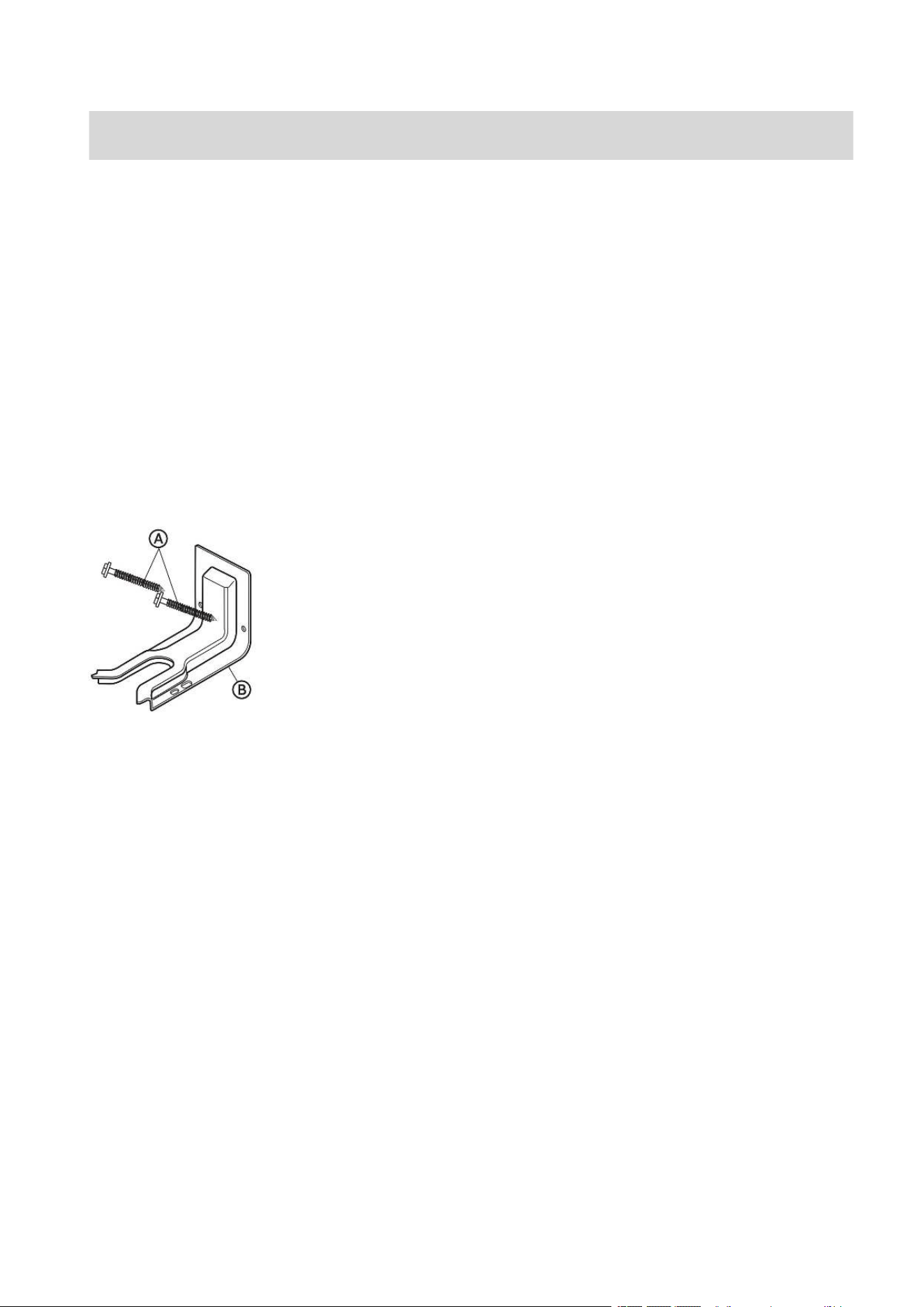
A 16 x 1 7/8" Screws (2)
B Anti-tip Bracket
NOTE: NOTE: The Anti-tip bracket must be securely mounted to the subfloor. The
thickness of flooring may require longer screws to anchor bracket to subfloor. Longer
screws are available from your local hardware store.
PARTS NEEDED
If using a power supply cord:
• A UL listed power supply cord kit marked for use with ranges. The cord should be rated
at 250 volts minimum, 40 amps or 50 amps that is marked for use with nominal 13/8"
(3.5 cm) diameter connection opening and must end in ring terminals or open-end
spade terminals with upturned ends.
• A UL listed strain relief.
If direct wiring:
• Flexible Metal Conduit
• UL Listed Conduit Connector
• 4-Wire or 3-Wire Electrical Cable (where local codes permit a 3-wire connection).
• UL Listed Wire Connectors
Check local codes. Check existing electrical supply. See the appropriate “Electrical
Requirements” section. It is recommended that all electrical connections be made by a
licensed, qualified electrical installer.
Installation Requirements

41
LOCATION REQUIREMENTS
VENTILATION
IMPORTANT: Observe all governing codes and ordinances.
• It is the installer’s responsibility to comply with installation clearances, if specified, on
the model/serial rating plate. The model/serial rating plate is located on the right-hand
side of the oven frame. Open oven door to view label. See label on back panel of range
for additional element and oven power ratings.
TEMPERATURE
IMPORTANT: Some cabinet and building materials are not designed to withstand the heat
produced by the oven for baking. Check with your builder or cabinet supplier to make sure
that the materials used will not discolor, delaminate or sustain other damage.
• Contact a qualified floor covering installer to check that the floor covering can
withstand at least 200°F (93°C).
• Use an insulated pad or 1/4" (0.64 cm) plywood under range if installing range over
carpeting.
GENERAL
• The range should be located for convenient use in the kitchen.
• Recessed installations must provide complete enclosure of the sides and rear of the
range.
• To eliminate the risk of burns or fire by reaching over heated surface units, cabinet
storage space located above the surface units should be avoided. If cabinet storage is
to be provided, the risk can be reduced by installing a range hood or microwave hood
combination that projects horizontally a minimum of 5" (12.7 cm) beyond the bottom of
the cabinets.
• All openings in the wall or floor where the range is to be installed must be sealed.
• Do not seal the range to the side cabinets.
• Grounded electrical supply is required. See “Electrical Requirements” section.
42
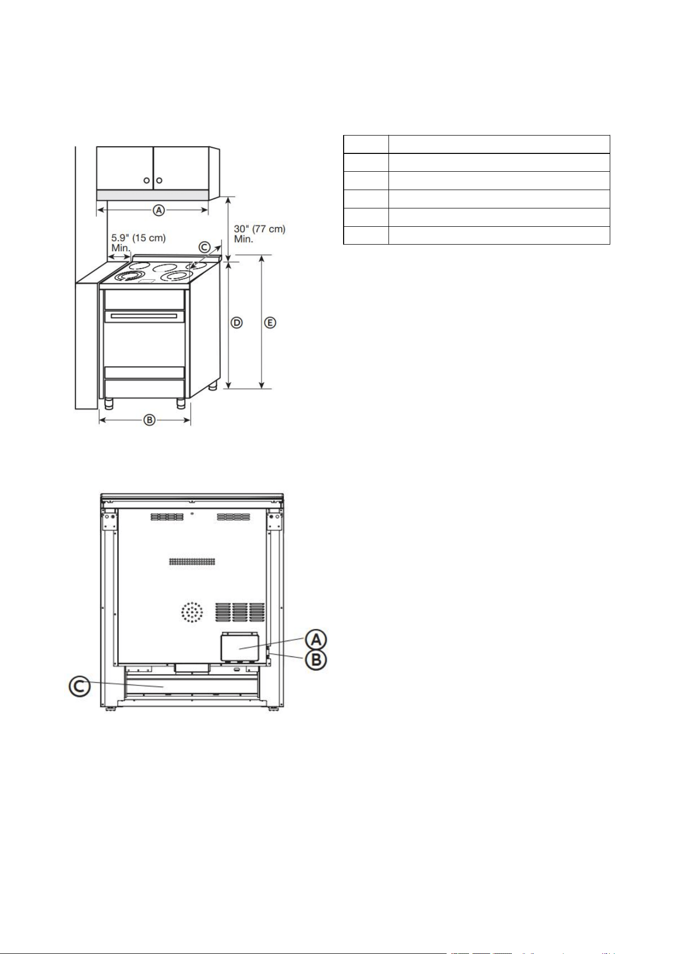
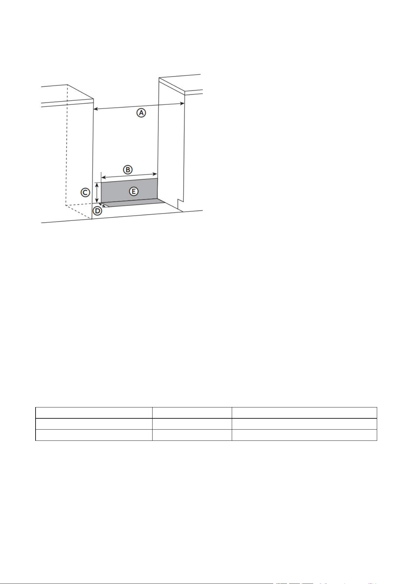
DIMENSIONS
PRODUCT/OPENING
Opening dimensions shown are for 25" (64 cm) countertop depth, 24" (61 cm) base cabinet
depth and 36" (91.4 cm) countertop height.
Dimension
A
30" (76 cm)
B
29 7/8" (76 cm)
C
25" (63.5 cm)
D
36" (91.4 cm)
E
37 3/4" (96 cm)
NOTE: Range can be raised approximately 1" (2.5 cm) by adjusting the leveling legs. Front of
door and drawer may extend farther forward depending on styling.
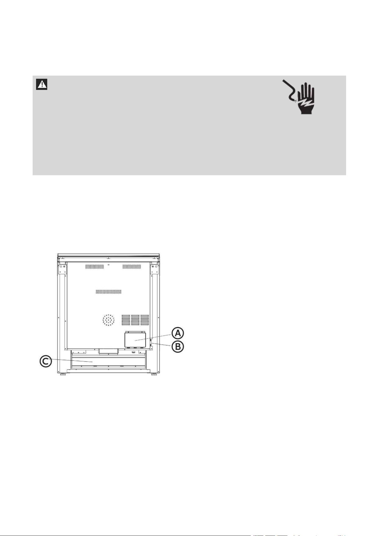
BACK OF RANGE
A Access Panel to Electrical Supply
Connection
B Power Cord Opening
C Recessed Area
43
POWER SUPPLY
IMPORTANT: To connect to an outlet in the wall, the electrical outlet must be recessed. If
the electrical outlet is in the floor, it can be either recessed or surface mounted.
A 30" (76 cm)
B 171/2" (44 cm)
C 71/4" (18.4 cm)
D 3" (7.6 cm)
E Recommended Location for Electrical
Outlet
ELECTRICAL REQUIREMENTS
IMPORTANT: This appliance is manufactured with the chassis connected to the neutral by
a green ground jumper wire. Use a 3-wire, UL listed, 50-amp power supply cord (pigtail); or
if local codes do not permit ground through the neutral, use a 4-wire power supply cord
rated at 250 volts, 50 amps and intended for use with ranges. The ground must be revised
so the green ground wire of the 4-wire power supply is connected to the chassis. See
“4-Wire Connection: “Power Supply Cord” and “Direct Wire - U.S.A. Only” “4-Wire
Connection (Ungrounded Neutral)” sections.
If codes permit and a separate ground wire is used, it is recommended that a qualified
electrical installer determine that the ground path is adequate and wire gauge is in
accordance with local codes.
To properly install your range, you must determine the type of electrical connection you
will be using and follow the instructions provided for it here.
• Range must be connected to the proper electrical voltage and frequency as specified
on the model/serial number rating plate. All models are dual rated, and designed to be
connected to either 120/208 or 120/240V AC, 60Hz, 3- wire or 4-wire, single-phase
power supply.
Voltage and Frequency
Amps
Circuit Required
240V, 60 Hz
50 A
50 Amp Circuit
208V, 60 Hz
43 A
45 Amp Circuit
• When a 4-wire, single phase 120/240 volt, 60 Hz., AC only electrical supply is available,
a 50-amp maximum circuit protection is required (or, if specified on the model/serial
rating plate, when a 4-wire, single phase 120/208 volt 60 Hz., AC only electrical supply
is available, a 45-amp maximum circuit protection is required).

44
• For direct wire installations, install a suitable conduit box (not furnished). An
appropriately sized, UL conduit connector must be used to correctly attach the conduit to
the junction box.
IMPORTANT: Local Codes may vary; installation electrical connections and grounding
must comply with all applicable local codes.
ELECTRICAL REQUIREMENTS - U.S.A. ONLY
Do not use an extension cord.
Be sure that the electrical connection and wire size are adequate and in conformance with
the National Electrical Code, ANSI/ NFPA No. 70-latest edition and all local codes and
ordinances.
A copy of the above code standards can be obtained from:
National Fire Protection
Association One Batterymarch
Park
Quincy, MA 02269
WARNING
Electrical Shock Hazard
The electrical power to the oven branch circuit must be shut off while line connections are
being made.
Do not use an extension cord with this appliance.
Electrical ground is required on this appliance. The free end of the green wire (the ground
wire) must be connected to a suitable ground. This wire must remain grounded to the
oven.
If cold water pipe is interrupted by plastic, non metallic gaskets, union connections or
other insulating materials, DO NOT use for grounding.
DO NOT ground to a gas pipe.
DO NOT have a fuse in the NEUTRAL or GROUNDING circuit. A fuse in the NEUTRAL or
GROUNDING circuit could result in an electrical shock.
Check with a qualified electrician if you are in doubt as to whether the appliance is
properly grounded.
Failure to do so could result in death, fire or electric shock.
The range is not equipped with a power cord. The range can be fitted with a 3 or 4-wire
NEMA 14-50 or 10-50 type SRDT or ST (as required) power cord rated at 250 volt AC
minimum, 50 amp, with 3 open-end spade lug connectors with upturned ends or closed
loop connectors and marked for use with ranges.
• A UL listed strain relief must be attached to the range to hold the power cord.

45
• Do not use an aluminum wire receptacle with copper-wired power cord and plug (or
vice versa). The proper wiring and receptacle is a copper-wired power cord with a
copper-wired receptacle.
• The electrical outlet should be located so that the power cord is accessible when the
range is in the installed position.
ELECTRICAL REQUIREMENTS - CANADA ONLY
WARNING
Electrical Shock Hazard
Disconnect power before servicing.
Plug into a grounded outlet.
Do not use an extension cord.
Failure to do so can result in death, fire, or electrical shock.
If codes permit and a separate ground wire is used, it is recommended that a qualified
electrical installer determine that the ground path is adequate and wire gauge are in
accordance with local codes.
Be sure that the electrical connection and wire size are adequate and in conformance with
CSA Standard C22.1, Canadian Electrical Code, Part 1 - latest edition, and all local codes and
ordinances.
A copy of the above code standards can be obtained from:
Canadian Standards
Association 178 Rexdale Blvd.
Toronto, ON M9W 1R3
CANADA
• Check with a qualified electrical installer if you are not sure the range is properly
grounded.
• This range is equipped with a CSA International Certified Power Cord intended to be
plugged into a standard 14-50R wall receptacle. Be sure the wall receptacle is within
reach of range’s final location.
• Do not use an extension cord.
46
IMPORTANT: This appliance shall be installed only by authorized persons and in
accordance with the manufacturer’s installation instructions, local gas fitting regulations,
municipal building codes, electrical wiring regulations, local water supply regulations.
STEP 1 - UNPACK RANGE
WARNING
Excessive Weight Hazard
Use two or more people to move and install range.
Failure to do so can result in back or other injury.
1. Remove shipping materials, tape and film from the range. Keep cardboard bottom under
range. Do not dispose of anything until the installation is complete.
2. Remove oven racks and parts package from oven and shipping materials.
3. To remove cardboard bottom, first take four cardboard corners from the carton. Stack
one cardboard corner on top of another. Repeat with the other two corners. Place them
lengthwise on the floor behind the range to support the range when it is laid on its back.
4. Using two or more people, firmly grasp the range and gently lay it on its back on the
cardboard corners.
5. Remove cardboard bottom.
NOTES:
• The leveling legs can be adjusted while the range is on its back.
• To place range back up into a standing position, put a sheet of cardboard or hardboard
on the floor in front of range to protect the flooring. Using two or more people, stand
range back up onto the cardboard or hardboard.
STEP 2 - INSTALL ANTI-TIP BRACKET
NOTE: An anti-tip bracket kit is provided with the range.
WARNING: Tip Over Hazard
• A child or adult can tip the range and be killed.
• Connect anti-tip bracket to rear range foot.
• Reconnect the anti-tip bracket, if the range is moved.
• Failure to follow these instructions can result in death or serious burns to children and
adults.
IMPORTANT: DO NOT completely remove the rear leveling legs. The anti-tip bracket
uses either the right-hand or left hand, rear leveling leg to secure the range to the floor.
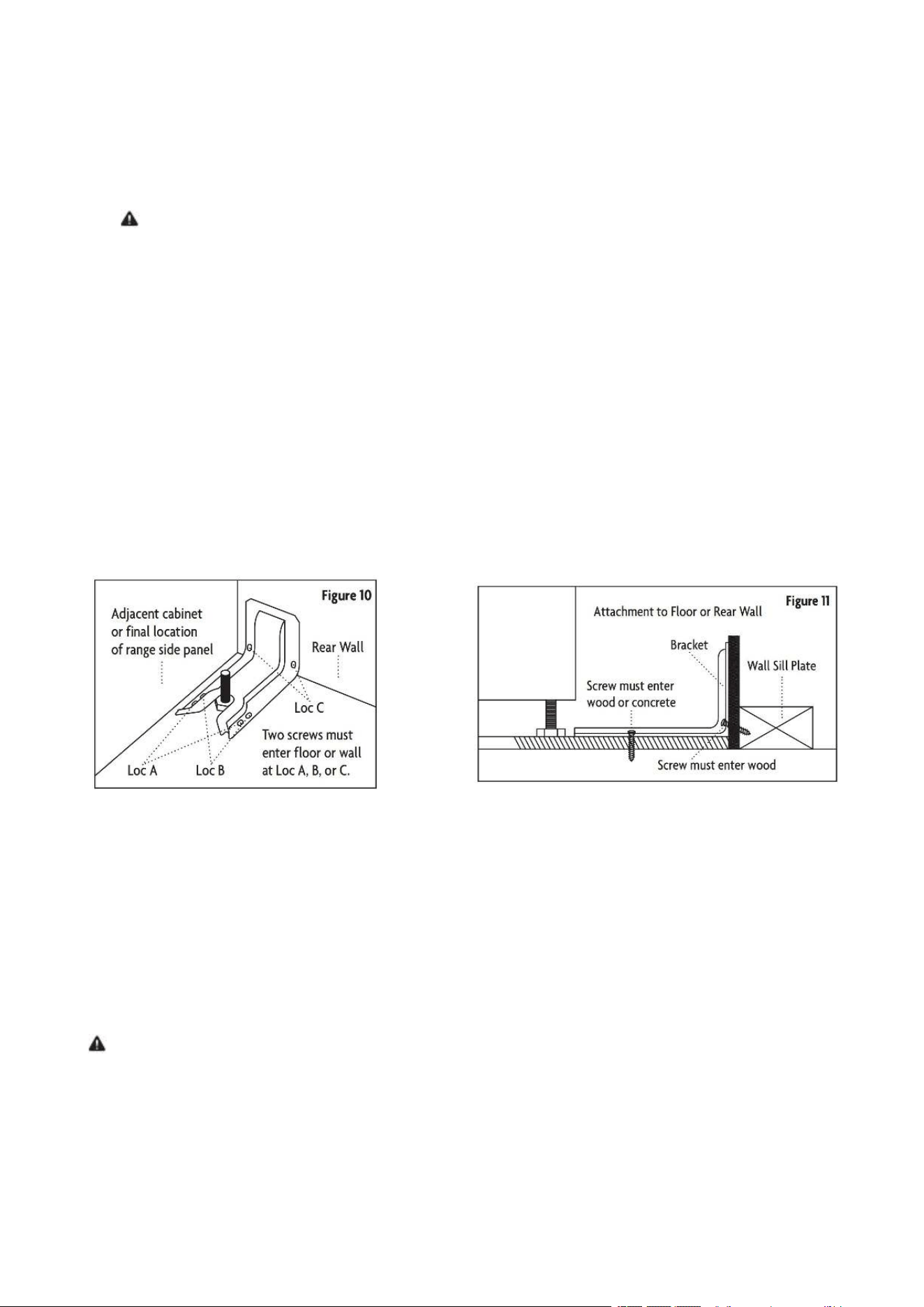
1: LOCATE THE BRACKET
Determine the final location of the range before attempting to install the bracket.
1. Place the bracket on the floor with the back edge against the rear wall. If the range does
not reach the rear wall, align the back edge of the bracket with the rear panel of the range
in its final location.
NOTE: If bracket does not touch the rear wall, you MUST screw bracket to FLOOR .
Installation Instructions
47
2. Position the side of the bracket against either the left or right cabinet. If there is no
adjacent cabinet, align the edge of the bracket with the side panel of the range in its final
location. If the countertop overhangs the cabinet, offset the bracket from the cabinet by
the amount of overhang.
3. Mark the location for the pair of holes to be used (see illustration above).
NOTE: For FLOOR installation use either Loc A or B. For REAR WALL installation use
Loc C.
2: SECURE THE BRACKET
The bracket must be screwed to either the FLOOR or REAR WALL.
FLOOR Installation:
• WOOD FLOOR: Use the screws provided to secure the bracket using the pair of marked
holes (either Loc A or B).
• CONCRETE FLOOR: Using a concrete bit, drill a 5/32” pilot hole 2” deep into the
concrete at the center of each of the marked holes (either Loc A or B). Use the screws
provided to secure the bracket into the floor.
REAR WALL Installation: Use the 2 screws provided to secure the bracket using the pair of
marked holes at Loc C. The screws MUST enter into a wood sill plate. If the wall contains
any metal studs or similar materials, then the floor must be used.
3: CHECK THE BRACKET
After installing the bracket, slide the range into its final location. The rear leveling leg must
be fully inserted into the ANTI-TIP bracket as shown in Step 1. To check if the bracket is
installed and engaged properly, look underneath the range to see that the rear leveling leg
is engaged in the bracket. On some models, the storage drawer or kick panel can be
removed for easier inspection. If visual inspection is not possible, slide the range forward,
confirm the anti-tip bracket is securely attached to the floor or wall, and slide the range
back so the leveling leg is under the anti-tip bracket. If the range is pulled from the wall for
any reason, always repeat this procedure to verify the range is properly secured by the
anti-tip bracket.
NOTE: The anti-tip bracket must be PROPERLY INSTALLED and the rear leveling leg must
be FULLY ENGAGED into the bracket to prevent the range from tipping. NEVER remove the
leveling legs. This will prevent the range from being secured to the ANTI-TIP bracket
properly.
Figure 10
Figure 11
48
STEP 3 - MAKE ELECTRICAL CONNECTION
After reading the requirements for each Electrical Connection method, follow the
instructions specic to your situation.
POWER CORD - U.S.A. ONLY
WARNING
Electrical Shock Hazard
Disconnect power before servicing.
Use a new 50 amp UL listed or CSA certied power supply cord for 240V, 45amp for 208V.
Plug into a grounded outlet.
Do not use an extension cord.
Failure to do so can result in death, re, or electrical shock.
3-WIRE CONNECTION: POWER SUPPLY CORD
IMPORTANT: Use this method only if local codes permit connecting chassis ground
conductor to neutral wire of power supply cord.
1. Disconnect power.
2. Remove the access panel located on the bottom right-hand side of the back panel to
uncover the electrical terminal block.
A Access Panel to Electrical Supply
Connection
B Power Cord Opening
C Recessed Area
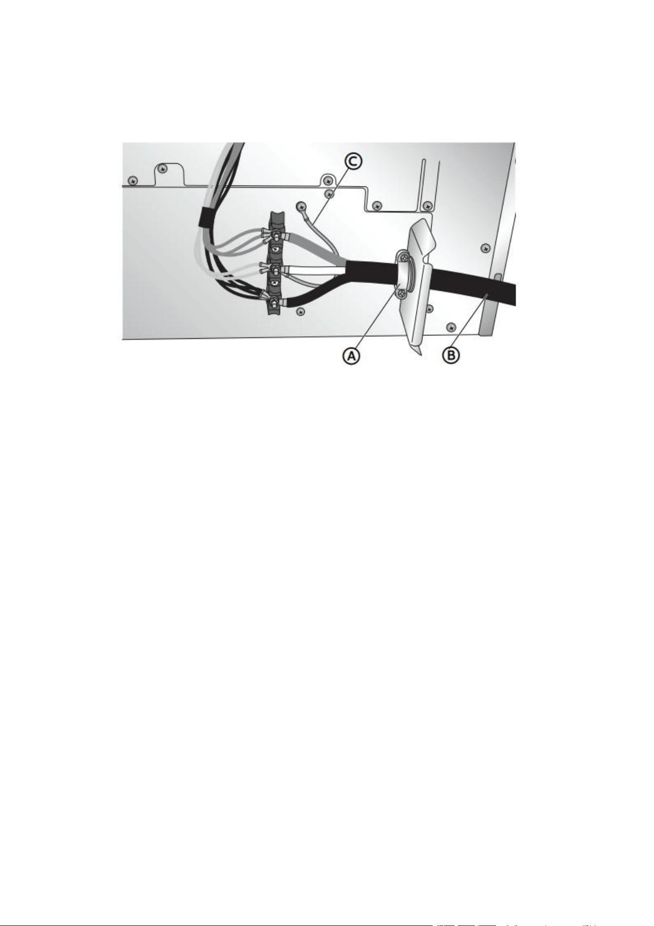
49
3. Install a UL listed strain relief (not provided) to the power cord opening in the bracket,
and then completely tighten the strain relief nut.
4. Thread the end of the power cord through the strain relief.
NOTE: Allow enough slack to connect the wires to the terminal block.
A UL Listed Strain Relief B Power Cord C Jumper Wire
5. Using a 5/16" nut driver and one of the -0-32 hex nuts, connect the neutral (white) wire
from the power cord to the center terminal block post along with the green jumper wire
from the range.
6. Using 10-32 hex nuts, connect the red and black wires from the power cord to the outer
posts of the terminal block with the corresponding red and black wires from the range.
7. Tighten the hex nuts completely, and then verify the connection.
NOTE: For power supply cord replacement, use only a power cord rated at 250 volts
minimum, 50-amps that is marked for use with nominal 1 3/8" (3.5 cm) diameter
connection opening, with ring terminals and marked for use with ranges.
8. Position the lower part of the strain relief under the power cord and tighten the strain
relief screws.
NOTE: Before tightening, make sure the strain relief is positioned over the cord and
NOT the wires.
9. Replace the electrical access panel.
10. Plug range into grounded outlet.
11. Tuck excess power cord into the recessed area of the back panel.
4-WIRE CONNECTION: POWER SUPPLY CORD
IMPORTANT: Use this method for new branch-circuit installations (1996 NEC), mobile
homes, recreational vehicles, or in an area where local codes prohibit grounding through
the neutral.
1. Disconnect power.
2. Remove the access panel located on the bottom right-hand side of the back panel to
expose the electrical terminal block.
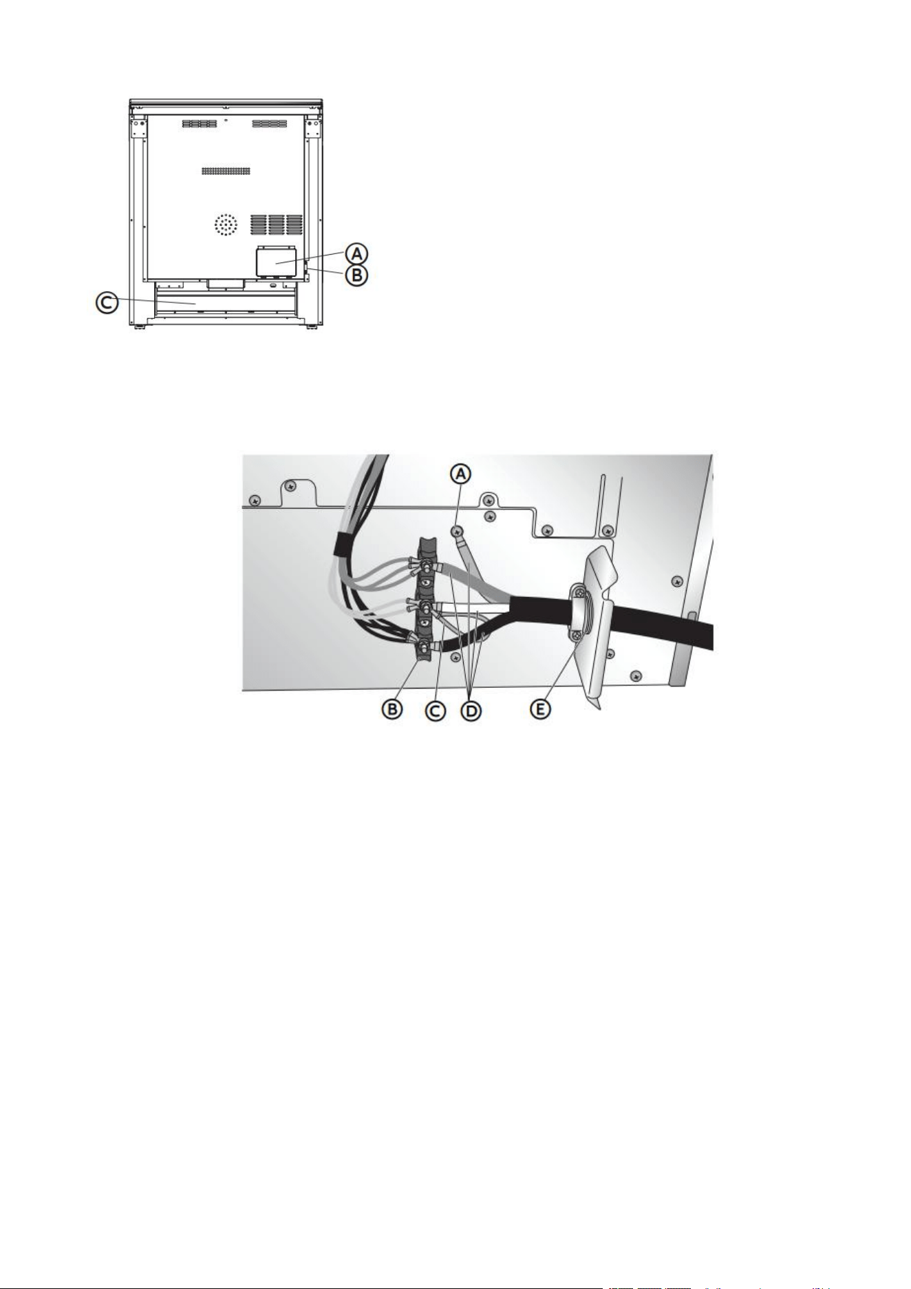
50
A Access Panel to Electrical Supply
Connection
B Power Cord Opening
C Recessed Area
3. Install a UL listed strain relief to the power cord opening in the support bracket, and fully
tighten the strain relief nut.
4. Feed the power supply cord through the strain relief. Allow enough slack to easily attach
the wiring to the terminal block.
A Ground Screw
B Terminal Block
C Jumper Wire
D Power Cord Wires
E UL Listed Strain Relief
5. Remove the green jumper wire from under the ground screw and replace with the green
wire from the power cord and tighten ground screw.
6. Loop the green jumper wire removed from the ground screw back onto its end that is
fastened to the center post on the terminal block.
7. Use 5/16" nut driver to connect the neutral (white) wire to the center terminal block post
with one of the 10-32 hex nuts.
8. Using 10-32 hex nuts, connect the red and black wires from the power cord to the outer
posts of the terminal block with the corresponding red and black wires from the range.
9. Tighten the hex nuts completely, and then verify the connection.
NOTE: For power supply cord replacement, use only a power cord rated at 250 volts
minimum, 50-amps that is marked for use with nominal 1 & 3/8" (3.5cm) diameter
connection opening, with ring terminals and marked for use with ranges.
10. Position the lower part of the strain relief under the power cord and tighten the strain
relief screws.
NOTE: Before tightening, make sure the strain relief is positioned over the cord and
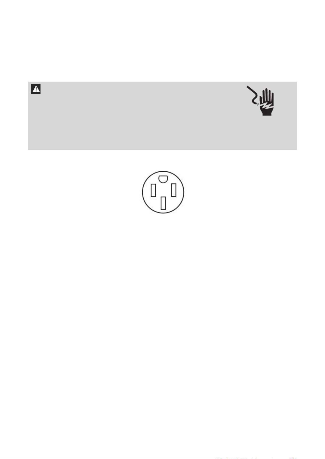
51
NOT the wires.
11. Replace the electrical access panel.
12. Plug range into grounded outlet.
13. Tuck excess power cord into the recessed area of the back panel.
POWER CORD - CANADA ONLY
1. Plug into a standard 14-50R grounded wall receptacle.
2. Go to STEP 4 - INSTALL RANGE.
WARNING
Electrical Shock Hazard
Plug into a grounded outlet.
Do not use an extension cord.
Failure to do so can result in death, re, or electrical shock.

52
DIRECT WIRE - U.S.A. ONLY
WARNING
Electrical Shock Hazard
Disconnect power before servicing.
Improper connection of aluminum house wiring and copper appliance leads can result in
an electrical hazard or fire. If the home has aluminum wiring, only use connectors designed
and UL listed for joining copper to aluminum and precisely follow the manufacturer's
recommended procedure. Aluminum-to-Copper connections must conform with local
codes.
Use 8 gauge copper or 6 gauge aluminum wire.
Electrically ground range.
Failure to do so can result in death, fire or electrical shock.
Be sure your appliance is properly installed and grounded by a qualified technician. Ask
your dealer to recommend a qualified technician or an authorized repair service.
• A circuit breaker is recommended.
• The range can be connected directly to the circuit breaker box (or fused disconnect)
through flexible or nonmetallic sheathed, copper or aluminum cable.
• Allow at least 6 ft (1.8 m) of slack in the line so that the range can be moved if servicing
is ever necessary.
• A UL listed conduit connector must be provided at each end of the power supply cable
(at the range and at the junction box).
• Wire sizes and connections must conform with the rating of the range.
• The tech sheet and wiring diagram are included with the range.
This appliance is manufactured with the chassis connected to the neutral by a green
ground jumper wire. After making sure that the power has been turned off, connect the
flexible conduit from the oven to the junction box using a UL listed conduit connector. The
Grounded Neutral and Ungrounded Neutral Graphics on the following pages and the
instructions provided, present the most common way of connecting the ovens. Your local
codes and ordinances, of course, take precedence over these instructions. Complete
electrical connections according to local codes and ordinances.
3-WIRE CONNECTION (GROUNDED NEUTRAL)
WARNING
Electrical Shock Hazard
Grounding through the neutral conductor is prohibited for new branch-circuit installations
(1996 NEC); mobile homes; and recreational vehicles, or in an area where local codes
prohibit grounding through the neutral conductor. For installations where grounding
through the neutral conductor is prohibited, see the Ungrounded Neutral graphic.
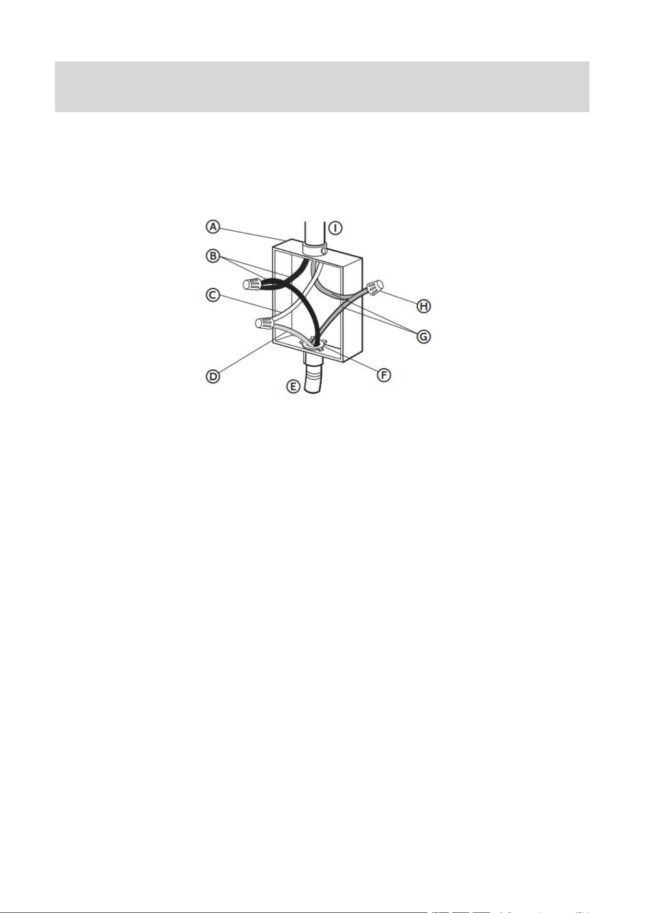
53
Connect to the House Electrical Supply
IMPORTANT: Use the 3-wire cable from home power supply where local codes permit a
3-wire connection.
1. Disconnect power.
Grounded Neutral
A Junction Box
B Black Wires
C Neutral (White) Wire
D Ground (Green or Bare)
Wire
E Cable from Range
F UL Listed Conduit
Connector
G Red Wires
H UL Listed Wire Connectors
I House Electrical Supply
2. Connect the 2 black wires B together using a UL listed wire connector.
3. Connect the neutral (white) wire C and the ground (green or bare) wire D (of the range
cable) using a UL listed wire connector.
4. Connect the 2 red wires G together using a UL listed wire connector.
5. Install junction box cover.
Connect to the Range
IMPORTANT: Use this method only if local codes permit connecting chassis ground
conductor to neutral wire of power supply cord.
1. Feed the electric cable wires through the flexible metal conduit.
NOTE: Allow enough slack to easily attach the wires to the terminal block.
2. Remove the access panel located on the bottom right-hand side of the back panel to
uncover the electrical terminal block.
Use grounding terminal or lead to ground unit.
Connect neutral terminal or lead to branch circuit neutral in usual manner.
Failure to do so could result in death, fire or electric shock.
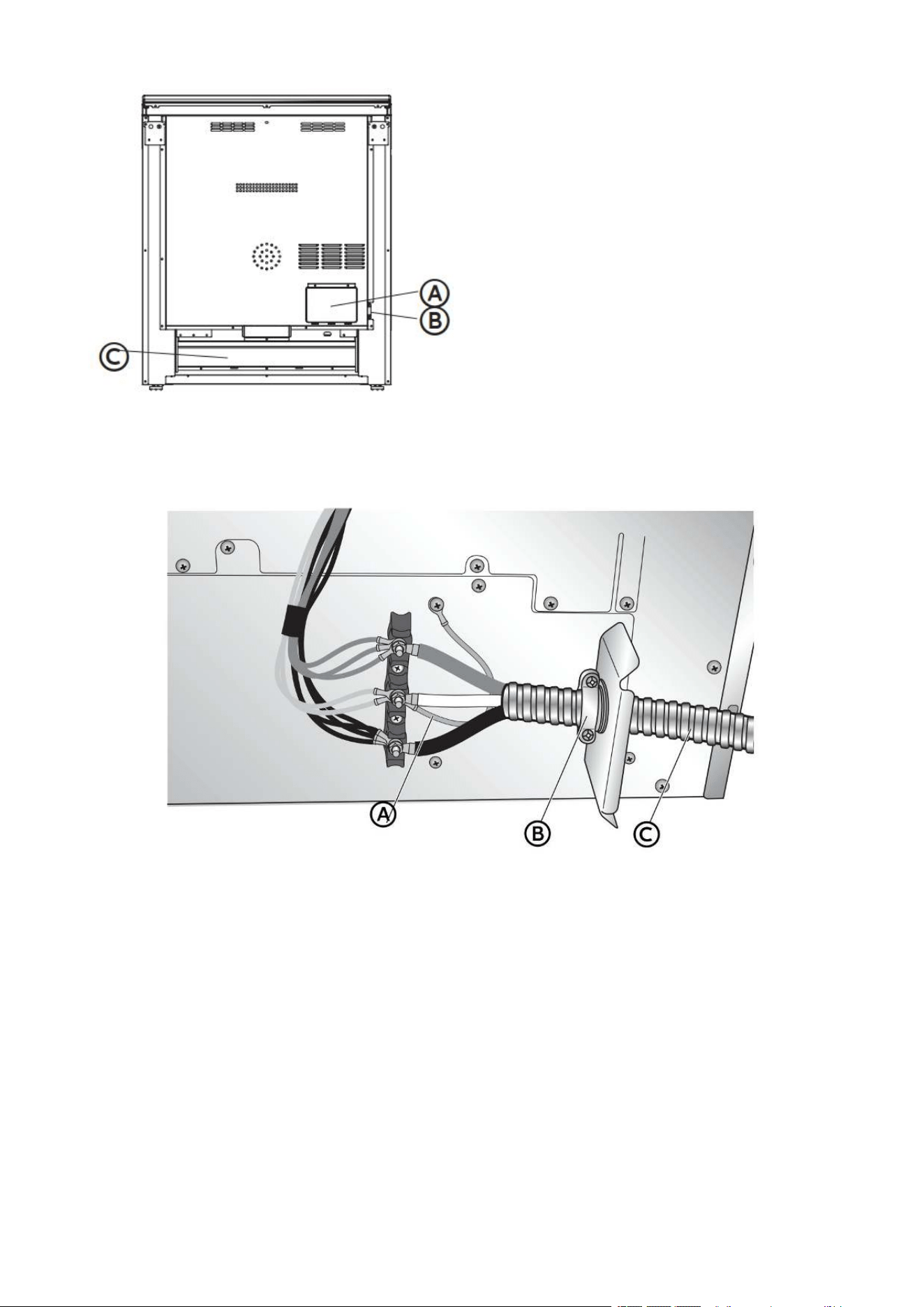
54
A Electrical Access Panel
G Conduit Opening
C Recessed Area
3. Install a UL listed strain relief (not provided) to the conduit opening in the bracket, and
then completely tighten the strain relief nut.
4. Thread the end of the conduit through the strain relief.
NOTE: Allow enough slack to connect the wires to the terminal block.
A Jumper Wire B UL Listed Strain Relief C Conduit
5. Using a 5/16" nut driver and one of the 10-32 hex nuts, connect the ground (green or bare)
wire from the exible metal conduit to the center terminal block post along with the green
jumper wire from the range.
6. Using 10-32 hex nuts, connect the red and black wires from the power cord to the outer
posts of the terminal block with the corresponding red and black wires from the range.
7. Tighten the hex nuts completely, and then verify the connection.
8. Position the lower part of the strain relief under the flexible metal conduit and tighten
the strain relief screws.
NOTE: Before tightening, make sure the strain relief is positioned over the flexible
metal conduit and NOT the wires.
9. Replace the electrical access panel.
10. Tuck excess conduit into the recessed area of the back panel.
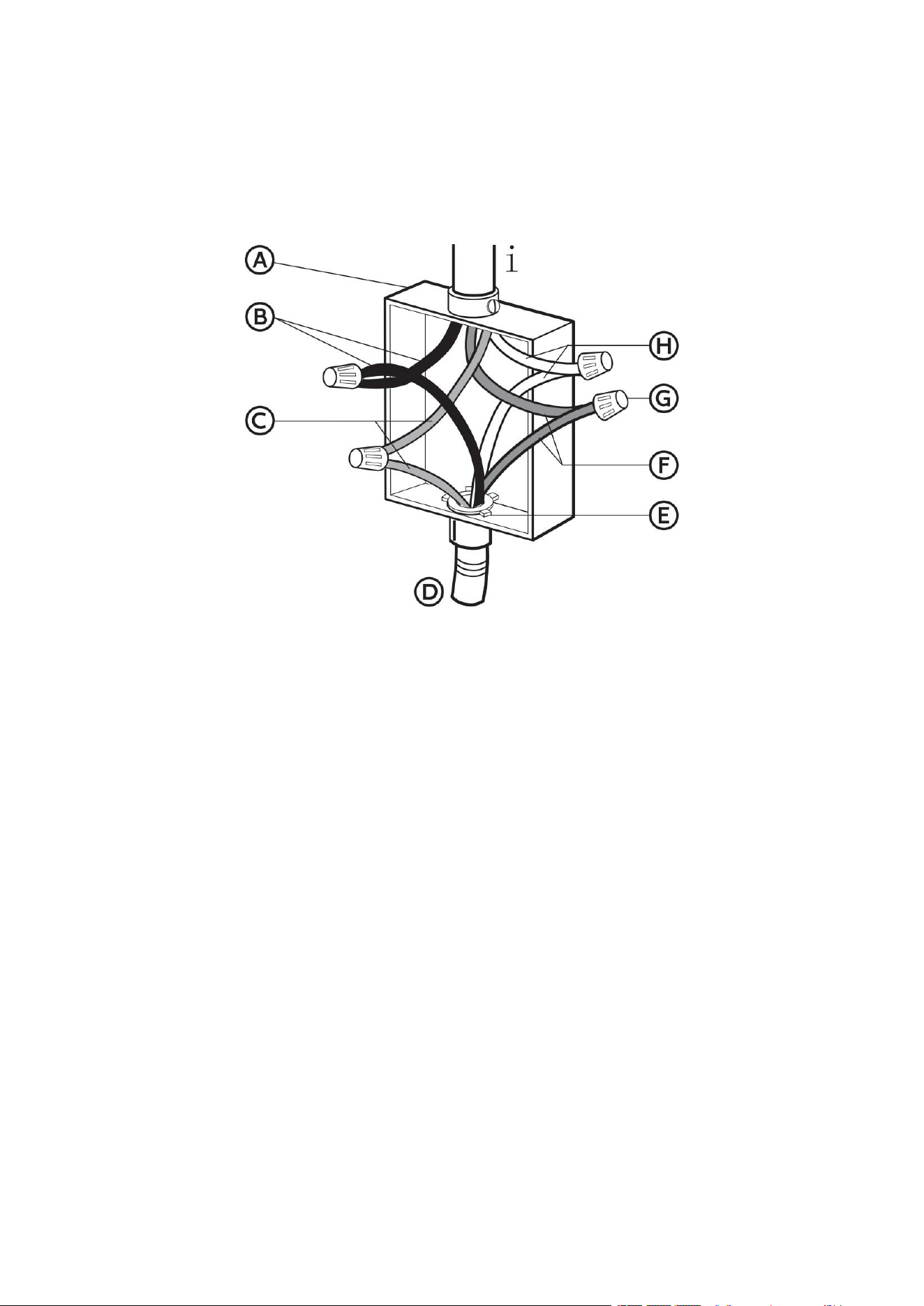
55
4-WIRE CONNECTION (UNGROUNDED NEUTRAL)
Connect to the House Electrical Supply - U.S.A. Only
IMPORTANT: Use the 4-wire cable from home power supply in the U.S. where local codes
do not allow grounding through neutral, new branch circuit installations (l99e NEC), mobile
homes and recreational vehicles, new construction and in Canada.
Ungrounded Neutral
A Junction Box
B Black Wires
C Red Wires
D Cable from Range
E UL listed or CSA Approved
Conduit Connector
F Ground (Green or Bare)
Wires
G UL Listed Wire Connector
H Neutral (White) Wires
I House Electrical Supply
1. Connect the 2 black wires B together using a UL listed wire connector.
2. Connect the 2 red wires C together using a UL listed wire connector.
3. Connect the 2 neutral (white) wires H together using a UL listed wire connector.
4. Connect the ground (green or bare) wire F from the range cable to the ground (green or
bare) wire (in the junction box) using a UL listed wire connector.
5. Install junction box cover.
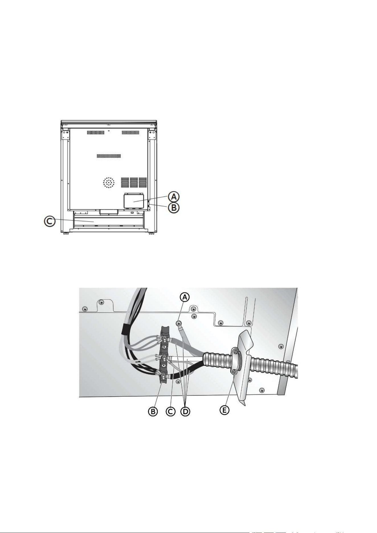
56
Connect to the Range
IMPORTANT: Use this method for new branch-circuit installations (1996 NEC), mobile
homes, recreational vehicles, or in an area where local codes prohibit grounding through
the neutral.
1. Feed the electric cable wires through the flexible metal conduit.
NOTE: Allow enough slack to easily attach the wires to the terminal block.
2. Remove the access panel located on the bottom right-hand side of the back panel to
expose the electrical terminal block.
A Electrical Access Panel
B Conduit Opening
C Recessed Area
3. Install a UL listed strain relief to the flexible metal conduit opening in the support bracket,
and fully tighten the strain relief nut.
4. Feed the flexible metal conduit through the strain relief. Allow enough slack to easily
attach the wiring to the terminal block.
A Ground Screw
B Terminal Block
C Jumper Wire
D Electrical Cable Wires
E UL Listed Strain Relief
5. Remove the green jumper wire from under the ground screw and replace with the green
wire from the flexible metal conduit and tighten ground screw.
57
6. Loop the green jumper wire removed from the ground screw back onto its end that is
fastened to the center post on the terminal block.
7. Use 5/16" nut driver to connect the neutral (white) wire to the center terminal block post
with one of the 10-32 hex nuts.
8. Using 10-32 hex nuts, connect the red and black wires from the power cord to the outer
posts of the terminal block with the corresponding red and black wires from the range.
9. Tighten the hex nuts completely, and then verify the connection.
10. Position the lower part of the strain relief under the flexible metal conduit and tighten
the strain relief screws.
NOTE: Before tightening, make sure the strain relief is positioned over the flexible
metal conduit and NOT the wires.
11. Replace the electrical access panel.
12. Tuck excess conduit into the recessed area of the back panel.
STEP 4 - INSTALL RANGE
IMPORTANT: If the range is moved to adjust the leveling legs, make sure when you move
the range back into its final location that the anti-tip bracket is engaged by repeating steps
1 through 9.
1. Slide range into final location, making sure rear leveling leg slides into anti-tip bracket.
Leave a l" (2.e cm) gap between the back of the range and the back wall.
2. Place the outside of your foot against the bottom front to keep the range from moving,
and then grasp the back of the range, as shown.
3. Slowly attempt to tilt the range forward.
If you encounter immediate resistance, the range foot is engaged in the anti-tip bracket.
Go to Step 8.
4. If the rear of the range lifts more than 1/2" (l.3 cm) off the floor without resistance, stop
tilting the range and lower it gently back to the floor. The range foot is not engaged in the
anti-tip bracket.

58
IMPORTANT: If there is a snapping or popping sound when lifting the range, the range may
not be fully engaged in the bracket. Check to see if there are obstructions keeping the
range from sliding to the wall or keeping the range foot from sliding into the bracket. Verify
that the bracket is held securely in place by the mounting screws.
5. Slide the range forward, and verify that the anti-tip bracket is securely attached to the
floor or wall.
6. Slide range back so the rear range foot is inserted into the slot of the anti-tip bracket.
7. Repeat steps 1 through 3 to ensure that the range foot is engaged in the anti-tip bracket.
If the rear of the range lifts more than 1/2" (l.3 cm) off the floor without resistance, the
anti-tip bracket may not be installed correctly. Do not operate the range without anti-tip
bracket installed and engaged.
8. Move the range into its final location. Check that the range is level by placing a level on
the oven bottom.
NOTE: The range must be level for optimum cooking and baking performance.
9. If needed, use a wrench to adjust the height of the leveling legs until the range is level
from side to side and front to back.
STEP 5 - COMPLETE INSTALLATION
1. Reconnect power at the circuit breaker or fuse box.
2. Turn on each element to check that it is heating correctly.
3. Turn on the oven to check that it is heating correctly.
NOTE: When the range has been on for 5 minutes, check for heat. If range is cold, turn
off the range and contact a qualified technician.
4. Check that the indicator lights on the control panel, and the interior oven lights
illuminate correctly.
If the range does not operate correctly, check the following:
• Household fuse is intact and tight; or circuit breaker has not tripped.
• Range is plugged into a grounded outlet.
• Electrical supply is connected.
Contact a qualified electrician to verify the electrical supply.
59
