Packaged Rooftop Unit - DOAS RTU Series
Installation, Operation, and Maintenance Manual
WARNING! FIRE OR EXPLOSION HAZARD
• Failure to follow safety warnings exactly could result in serious injury, death or property damage.
• Make sure to read and understand the installation, operation and service instructions in this manual.
• Improper installation, adjustment, alteration, service or maintenance can cause serious injury, death or
property damage.
• Read the installation, operating and maintenance instructions thoroughly before installing or servicing
this equipment. ALWAYS disconnect power and gas prior to working on unit.
FOR YOUR SAFETY
Do not store or use gasoline or other flammable vapors and liquids in the vicinity of this or any other
appliance. Installation and service must be performed by a qualified installer, service agency or gas supplier.
WHAT TO DO IF YOU SMELL GAS:
• Do not try to light any appliance. Do not touch any electrical switch; do not use any phone in your
building.
• Leave the building immediately. Immediately call your gas supplier from a phone remote from the
building.
• Follow the gas supplier’s instructions. If you cannot reach your gas supplier, call the fire department.
IMPORTANT
Some units may contain an energy recovery wheel. By virtue of their design, all energy recovery wheels
allow a level of return/exhaust air and contaminants to be recirculated into the supply airstream. Accepting
and operating this unit with or without the energy recovery wheel in operation increases the risk of airborne
bacteria, virus and contaminant spread between the return/exhaust air, into the fresh airstream.
In accordance with ANSI/ASHRAE/ASHE Standard 170-2017, energy recovery wheel technology should not
be used as a means of ventilation for certain Health Care Facilities. An ASHRAE Position Document on
Infectious Aerosols, approved by ASHRAE Board of Directors, dated April 14, 2020, also recommends that
energy recovery devices be bypassed for non-health care facility ventilation to help reduce the spread of
virus.
Any reduction of outdoor air % or volume below what this unit was designed for elevates the risk of airborne
bacteria, virus and contaminant recirculation back into the fresh airstream and the space.
Operating this unit with an exhaust level less than 50% of the supply level nullifies all return on investment
statements and limits the amount of energy recovery.
This unit, including the energy recovery wheel, must be serviced and maintained as per the Installation and
Operation Manual’s recommended frequencies.
RECEIVING AND INSPECTION
Upon receiving unit, check for any interior and exterior damage, and if found, report it immediately to the
carrier. Check that all accessory items are accounted for and free of damage. Turn the blower wheel by hand
to verify free rotation and check the damper (if supplied) for free operation.
A0033507
November 2021 Rev 06

2

3
Table of Contents
WARRANTY ................................................................................... 4
Coastal Applications .................................................................. 4
Furnace Warranty ...................................................................... 4
CERTIFICATIONS .......................................................................... 4
Listings and Standards .............................................................. 4
INSTALLATION .............................................................................. 5
Mechanical ................................................................................. 5
Inspection on Arrival ............................................................. 5
Unit Location - Site Preparation ............................................ 5
Rigging ....................................................................................... 8
Curb and Ductwork .................................................................... 9
Duct Hanger Dimensions .................................................... 11
Curb and Adapter .................................................................... 13
Supply Duct Pad Mount Clearances ........................................ 14
Duct Static Pressure Control .............................................. 15
Typical Submittal Drawing .................................................. 16
Furnace Condensation Drain ................................................... 17
Cooling Coil Trap ................................................................ 18
Heat Drain Kit ..................................................................... 18
Gas .......................................................................................... 19
High Turndown Furnace ..................................................... 19
Strainer ............................................................................... 20
High Altitude and Gas Type Orifice Sizing ............................... 21
LP Conversion Kit for RTU Series ........................................... 23
Pre-Conversion Unit Check-Out .............................................. 24
Gas Conversion Instruction ................................................ 25
Electrical .................................................................................. 26
Building to Unit Power Wiring Connection .......................... 27
Site Preparation – Controls ................................................ 27
HMI and Remote Room Sensor Installation ............................ 28
Typical Wiring Schematic ................................................... 29
Variable Frequency Drive (VFD) .............................................. 30
Variable Frequency Drive (VFD) Installation ...................... 30
Input AC Power .................................................................. 30
VFD Output Power ............................................................. 31
VFD Programming .............................................................. 31
ACTECH SMV VFD ............................................................ 32
Make-up Air (MUA) Board Connectors ............................... 33
Optional Components .............................................................. 44
AC Interlock ........................................................................ 44
Burner Interlock .................................................................. 44
Electric Cabinet Heater ....................................................... 44
Component Location ................................................................ 44
Electric Heater Option ........................................................ 51
Compressor Information .......................................................... 52
VZH 044/035/028 ............................................................... 52
Compressor VZH 065 ......................................................... 52
Compressor VZH 088/117/170 ........................................... 53
Compressor Drive Information ................................................. 54
CDS803 Quick Menu Navigation ........................................ 54
CDS803 Main Menu Navigation ......................................... 54
CDS302/303 Quick Menu navigation ................................. 55
CDS302/303 Main Menu .................................................... 55
OPERATION ................................................................................. 56
HMI Configuration Menu Access ............................................. 56
Remote (HMI) Control Panel .............................................. 56
HMI Notification Letters ...................................................... 56
Configuring HMI ....................................................................... 57
Communication ................................................................... 57
Advanced Options .............................................................. 57
Status ................................................................................. 57
About .................................................................................. 57
Scheduling .......................................................................... 58
Fan Speed and Damper Position Presets ............................... 58
Menu Descriptions ................................................................... 59
Menu Tree ............................................................................... 70
UNIT OPERATION ....................................................................... 82
Start-Up Procedure ............................................................. 82
Start-Up Procedure Heating .....................................................83
Furnace Start-Up Summary ................................................83
High Fire Burner Adjustment ...............................................83
Low-Fire Burner Adjustment ...............................................84
Final Start-Up Procedure ....................................................84
Sequence of Operation ............................................................85
Operation Summary - Gas Heating .....................................85
Flame Safety Control (FSC) .....................................................86
Modulating Stage Sequence ....................................................86
MUA Board and High Fire Start ...............................................86
Re-Circulating Control Options ................................................87
Powered Exhaust .....................................................................87
Outdoor Air Configuration ........................................................87
Programmable Thermostat ......................................................87
Heating, Cooling, Defrost, and Reheat ....................................88
Economizer ..............................................................................91
Psychrometric Chart ................................................................92
Fixed Dry Bulb Economizer ...............................................92
Differential Dry Bulb Economizer .......................................92
Fixed Total Economizer ......................................................93
Differential Total Economizer ..............................................93
Energy Recovery (Optional) .....................................................94
Purge and Pressurization .........................................................94
Drive Motor .........................................................................95
Frost Protection (Optional) ..................................................95
Variable Speed Frost Prevention ........................................95
Energy Recovery Exhaust Hoods ............................................95
Exhaust Fan .............................................................................95
Slide-Out Wheel .......................................................................95
Field Installation of Large ERVs ...............................................96
Network ....................................................................................98
BACnet ...............................................................................98
Device Instance, MAC Address, Baud Rate .......................99
Changing the IP Address ..................................................100
LonWorks ..........................................................................101
DDC Control Points (BACnet) ................................................102
DDC Notes ........................................................................106
DDC Faults .......................................................................107
SERVICE INFORMATION ..........................................................109
Basic Service .........................................................................109
Monitoring the A/C System ...............................................109
Monitoring with Gauge Set ................................................110
Recovering Refrigerant from the System ..........................110
Nitrogen Purging ...............................................................111
Pressure Testing ...............................................................111
Evacuating the System .....................................................111
Charging an Empty System ..............................................112
Charging System Low on Refrigerant ...............................113
Removing Manifold Gauge Set .........................................113
Troubleshooting .....................................................................114
System Troubleshooting Chart .........................................114
HMI Fault Codes ...............................................................115
Compressor Drive VFD Troubleshooting Chart .....................119
Compressor Troubleshooting Chart .......................................121
Airflow Troubleshooting Chart ................................................122
Furnace Troubleshooting Chart .............................................123
Superheat and Subcooling .....................................................124
Component Check/Testing ....................................................125
MAINTENANCE ..........................................................................137
General Maintenance .............................................................137
Every 3 Months ......................................................................137
Heating Season ................................................................138
Cooling Season ................................................................138
Maintenance Quick Reference Chart ................................138
Coil Cleaning Procedure ...................................................
139
F
ilters ................................................................................140
Start-Up and Maintenance Documentation ............................143

4
WARRANTY
This unit comes with a standard 5-year parts warranty from date of shipment to be free from defects in
materials and workmanship, under normal use and service. An extended 10-year non-prorated parts
warranty is available at no extra charge when units are remotely monitored and maintained through a
Service Preventative Maintenance subscription (terms and conditions apply).
This warranty shall not apply if:
1. The equipment is not installed by a qualified installer per the MANUFACTURER’S installation
instructions shipped with the product.
2. The equipment is not installed in accordance with Federal, State, and/or Local codes and regulations.
3. The equipment is misused or neglected, or not maintained per the MANUFACTURER’S maintenance
instructions.
4. The equipment is not operated within its published capacity.
5. The invoice is not paid within the terms of the sales agreement.
The MANUFACTURER shall not be liable for incidental and consequential losses and damages potentially
attributable to malfunctioning equipment. Should any part of the equipment prove to be defective in
material or workmanship within the standard 5-year warranty period or the extended 10-year Preventative
Maintenance subscription, upon examination by the MANUFACTURER, such part will be repaired or
replaced by MANUFACTURER at no charge. The BUYER shall pay all labor costs incurred in connection
with such repair or replacement. Equipment shall not be returned without MANUFACTURER’S prior
authorization, and all returned equipment shall be shipped by the BUYER, freight prepaid to a destination
determined by the MANUFACTURER.
NOTE: To receive warranty coverage, register this product by filling out the Start-up and
Maintenance Document on page 143. Fax the form to 1-919-554-9374 or call 1-866-784-6900 for
email information.
Coastal Applications
Units installed within 1-mile of salt-water coasts and waterways must be equipped with an E-Coated
Outdoor Coil. Position the unit so the fresh air inlet and outdoor coil are protected from direct salt spray.
Failure to protect the fresh air inlet and outdoor coil from direct salt spray will void the unit’s warranty.
Furnace Warranty
Subject to all terms stated herein, the MANUFACTURER warrants to BUYER the stainless steel heat
exchanger to be free from defects in material and workmanship under normal use and service for
25-years from the date of manufacture and warranty is limited to replacement of the heat exchanger only.
CERTIFICATIONS
Listings and Standards
This unit is ETL-listed to the following standards:
• Standard for Safety Heating and Cooling Equipment ANSI/UL 1995, CSA 22.2 no. 236
• American National Standard/CSA Standard for Gas Unit Heaters and Gas-Fired Duct Furnaces ANSI
Z83.8-2016, CSA 2.6-2016
This unit has been tested in accordance to the following standards:
• ANSI/AHRI Standard 340/360 – 2007
• ANSI/ASHRAE Standard 37 – 2009

5
INSTALLATION
It is imperative that this unit is installed and operated with the designed airflow, gas, and electrical supply in
accordance with this manual. If there are any questions about any items, please call the service
department at 1-866-784-6900 for warranty and technical support issues.
Mechanical
Inspection on Arrival
1. Inspect unit on delivery.
2. Photograph any visible damage.
3. Report any damage to the delivery carrier.
4. Request a written inspection report from the Claims Inspector to substantiate a claim.
5. File a claim with the delivery carrier.
6. Check unit’s rating plate to verify proper electric and fuel type to meet job requirements.
7. Compare unit received with description of product ordered.
Unit Location - Site Preparation
• Do not locate any gas-fired equipment near corrosive, explosive vapors such as chlorinated or acid
vapors.
• Avoid overhead power lines, or other utility access points to prevent accidental contact or damage.
• Provide clearance around the installation site to safely rig and lift the equipment into its final position
onto adequate supports. Refer to the manufacturer’s estimated weights.
• Consider general service and installation space when locating the unit.
• Locate the unit close to the space it will serve to reduce long and twisted duct runs.
• Do not allow the air intake to face prevailing winds. The airflow switch may trip in high winds.
• Situate the unit above ground or at roof level high enough to prevent precipitation from being drawn
into its inlet.
• The inlet must also be located at least 10 feet away from any exhaust vents.
• The inlet must be in accordance with the applicable building code provisions for ventilation air.
• The unit must have adequate structural support, or the equipment or building could be damaged.
• Do not alter or otherwise restrict combustion or ventilation openings.
IMPORTANT
For gas units, to prevent premature heat exchanger failure, do not locate any gas fired unit in
areas where chlorinated, halogenated, or acid vapors are present in the atmosphere.
6
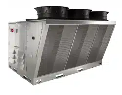
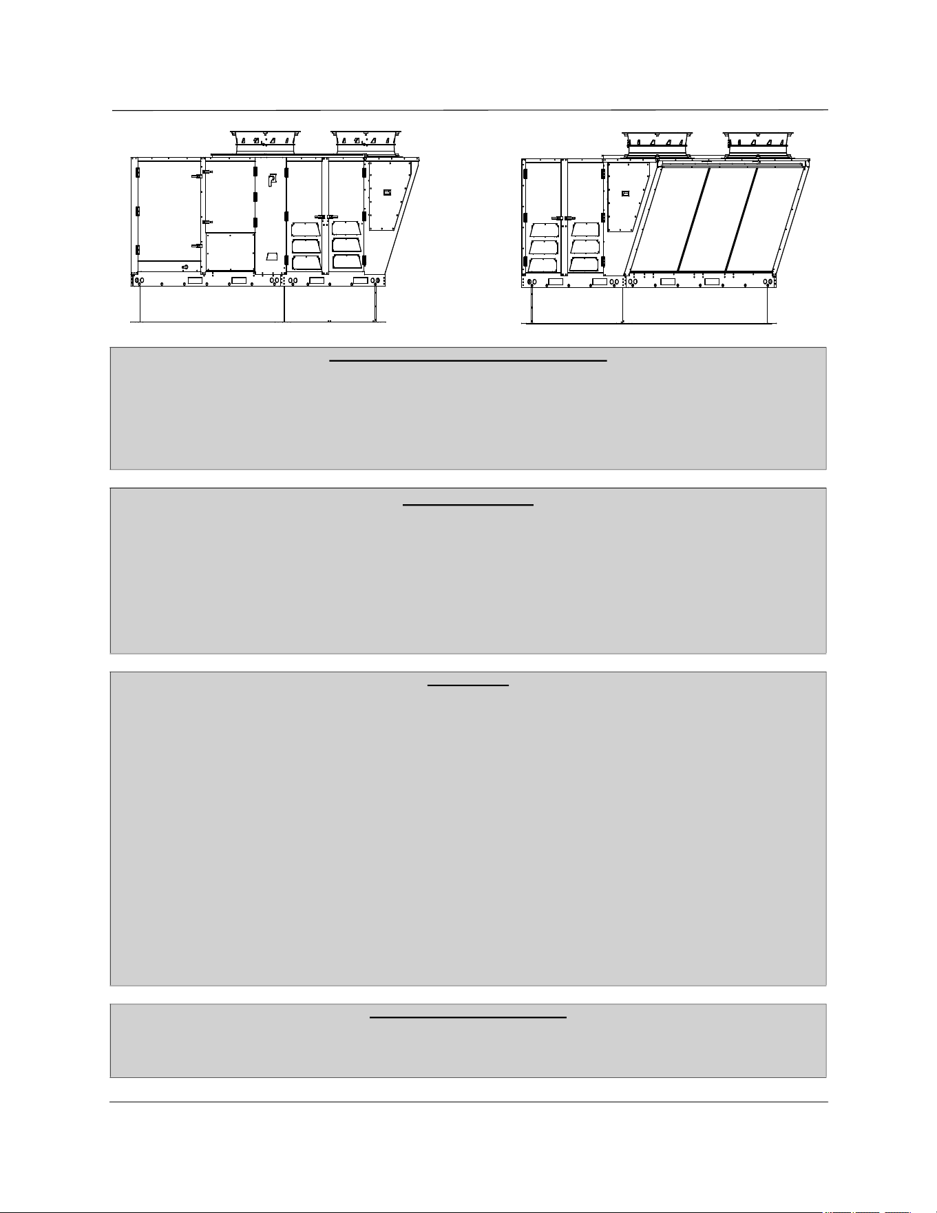
Figure 1 - Unit Clearance
CLEARANCE TO COMBUSTIBLE MATERIALS
This equipment may be installed with clearances from the equipment to combustible material not
less than 0 inches from the top, bottom, condenser side, front and back. The flue side must be
installed 3 feet from combustible materials. Refer to Figure 1 for clearance details.
SERVICE CLEARANCE
For service accessibility and performance, this unit must have at least 3 feet of clearance on the
intake and supply sides. Size 1, 2, and 3 units should have 3 feet of clearance on the condensing
coil side, and size 4 units should have 4 feet. Clearance above condenser fans should be at least
10 feet. Refer to Figure 1 for clearance details.
Size 1, 2, and 3 Unit Clearance
CLEARANCE TO
COMBUSTIBLES 0 FT.
Size 4 Unit Clearance
CLEARANCE TO
COMBUSTIBLES 0 FT.
SERVICE
CLEARANCE 4 FT.
CLEARANCE TO
COMBUSTIBLES 0 FT.
SERVICE
CLEARANCE 3 FT.
SERVICE CLEARANCE
AND CLEARANCE TO
COMBUSTIBLES 3 FT.
CLEARANCE TO
COMBUSTIBLES 0 FT.
CLEARANCE TO
COMBUSTIBLES 0 FT.
SERVICE
CLEARANCE 3 FT.
CLEARANCE TO
COMBUSTIBLES 0 FT.
SERVICE
CLEARANCE 3 FT.
SERVICE CLEARANCE AND
CLEARANCE TO
COMBUSTIBLES 3 FT.
7
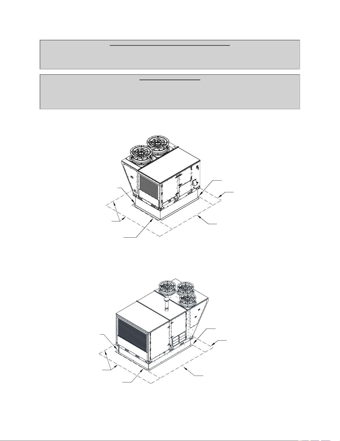
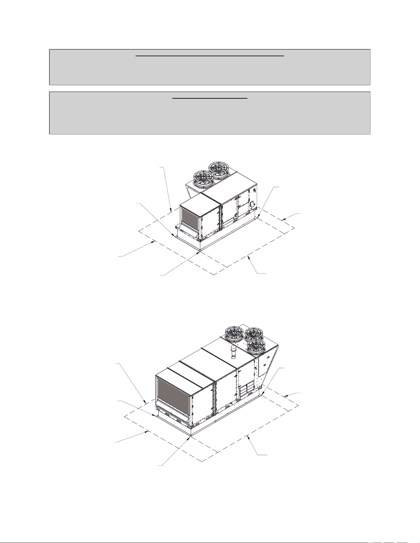
Figure 2 - ERV Unit Clearances
CLEARANCE TO COMBUSTIBLE MATERIALS
This equipment may be installed with clearances from the equipment to combustible material not
less than 0 inches from the top, bottom, condenser side, front and back. The flue side must be
installed 3 feet from combustible materials. Refer to Figure 2 for clearance details.
SERVICE CLEARANCE
For service accessibility and performance, this unit must have at least 3 feet of clearance on the
intake and supply sides. Size 2 and 3 ERV units should have 3 feet of clearance on the condensing
coil side, and size 4 ERV units should have 4 feet. Clearance above condenser fans should be at
least 10 feet. Refer to Figure 2 for clearance details.
Size 2 and 3 Unit Clearance
Size 4 Unit Clearance
SERVICE
CLEARANCE 4 FT.
CLEARANCE TO
COMBUSTIBLES 0 FT.
SERVICE CLEARANCE
AND CLEARANCE TO
COMBUSTIBLES 4 FT.
CLEARANCE TO
COMBUSTIBLES 0 FT.
SERVICE
CLEARANCE
3 FT.
CLEARANCE TO
COMBUSTIBLES
0 FT.
SERVICE
CLEARANCE
4 FT.
SERVICE
COMBUSTIBLES 0 FT.
CLEARANCE TO
COMBUSTIBLES
0 FT.
SERVICE
CLEARANCE
3 FT.
CLEARANCE TO
COMBUSTIBLES 0 FT.
SERVICE CLEARANCE
AND CLEARANCE TO
COMBUSTIBLES 3 FT.
SERVICE
CLEARANCE 3 FT.
CLEARANCE TO
CLEARANCE
4 FT.
8
Rigging
Spreader bars must be used and should extend past the edges of the equipment to avoid damage to the
casing. Not using spreader bars may cause damage to the unit casing. Refer to Figure 3 for rigging
details.
WARNING: DO NOT LIFT UNIT BY THE INTAKE LOUVER, OR DOOR OPENINGS – USE ALL
LIFTING
POINTS PROVIDED WITH A SPREADER BAR OR SLINGS UNDER THE UNIT – USE CARE NOT TO
DAMAGE COILS, SWITCHES OR PROTRUDING SHEET METAL COMPONENTS.
• Units are supplied with four lifting eyes on the bottom corners of the structural rails.
• Always use spreader bars to prevent damage to the unit casing.
• Test lift the unit approximately 2 feet to verify proper center of gravity lift point. To avoid dropping unit,
re-position lifting point if unit is not level. Failure to properly lift unit could result in unit dropping and
possibly crushing operator/technician, which could result in death or serious injury and possible
equipment or property-only damage.
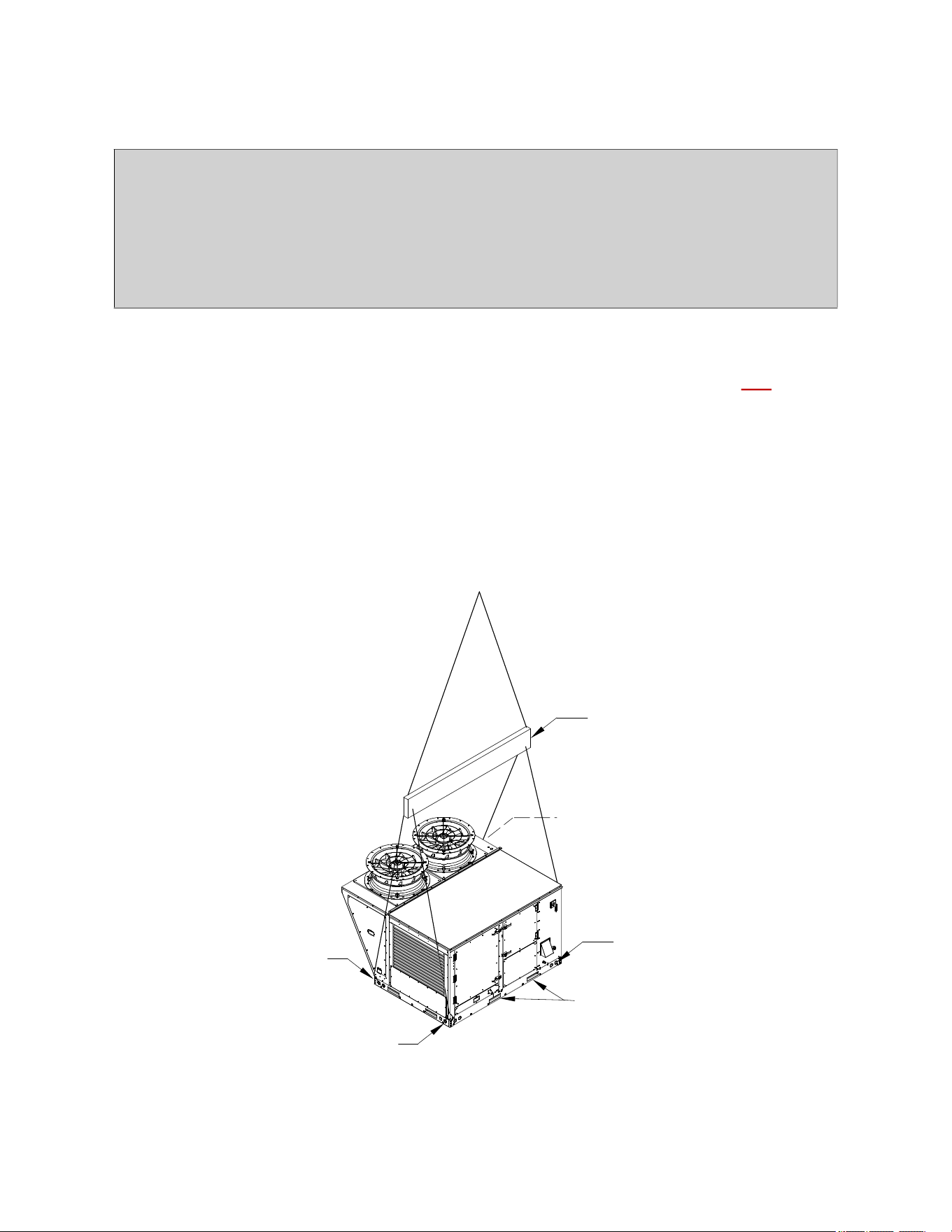
Figure 3 - Rigging (Size 2 Unit Shown)
WARNING!!
Ensure that all the lifting equipment used is properly rated for the weight of the unit being lifted.
Each of the cables (chains or slings), hooks, and shackles used to lift the unit must be capable of
supporting the entire weight of the unit. Lifting cables (chains or slings) may not be of the same
length. Adjust as necessary for even unit lift. Other lifting arrangements could cause equipment
or property damage. Failure to follow instructions above or properly lift unit could result in unit
dropping and possibly crushing operator/ technician which could result in death or serious
injury.
Spreader
Bar
Lifting Eyes
Located in 4 Corners
Lifting Eyes
Located in 4 Corners
Lifting Eyes
Located in 4 Corners
Lifting Eyes
Located in 4 Corners
Lifting Eyes
Located in 4 Corners
Forklift
Pockets
9
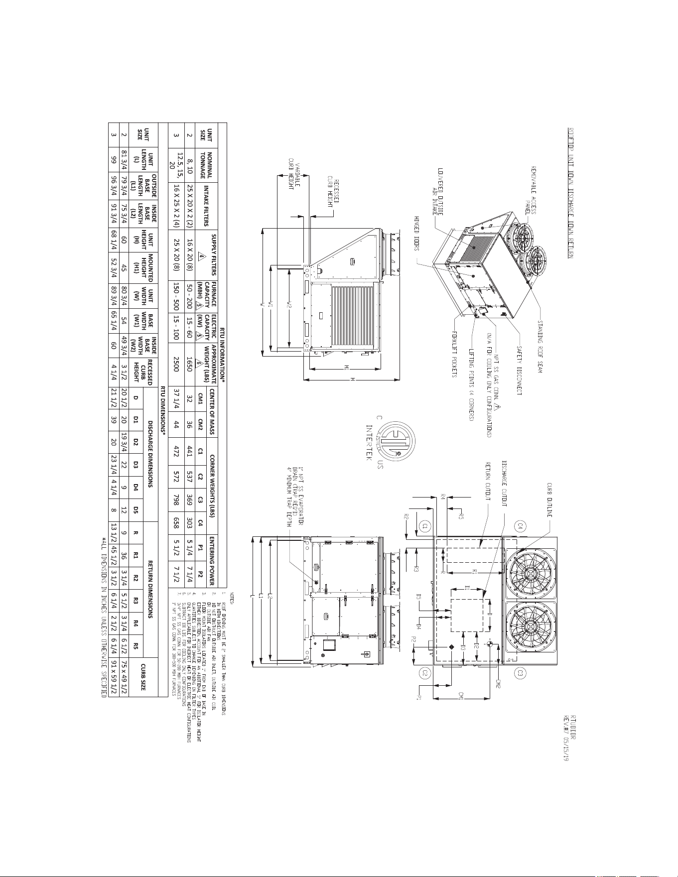
Curb and Ductwork
This unit was specified for a specific CFM and static pressure. The ductwork attached to this unit will
significantly affect airflow performance. When using rectangular ductwork, elbows must be radius throat,
radius back with turning vanes. Flexible ductwork and square throat/square back elbows should not be
used. Any transitions and/or turns in the ductwork near the fan outlet will cause system effect. System
effect will drastically increase the static pressure and reduce airflow. Table 1 and Table 2 detail the
minimum fan outlet duct sizes required for optimal fan performance.
• Follow SMACNA guides and manufacturer’s requirements for the remaining duct run. Units
designed for rooftop installation should be installed on a prefabricated or factory-built roof curb. Follow
curb manufacturer’s instructions for proper curb installation.
• Do not use unit to support ductwork in any way. This may cause damage to the unit.
• If installed in a geographical area where snow accumulates, the unit should be installed on a curb and/
or rail elevated not less than 12-inches above any surface. Verify installation meets local code height
requirements.
• Verify duct connection and unit supply outlet are properly aligned and sealed. Use gasket between the
curb and unit (Figure 4).
• The curb and unit must be level, or the unit may leak or be damaged. If necessary, use shims to level
the unit. Shims may be required depending upon curb installation and roofing material.
• Secure unit to curb with all available mounting points through vertical portion of the base assembly
rails (Figure 4). Use lug screws, anchor bolts, or other suitable fasteners (not furnished).
• Check all fasteners are secure and tight.
WARNING!!
Failure to properly size ductwork may cause system effects and reduce the performance of the
equipment.
Table 1 - Recommended Supply Ductwork Sizes Up/Down Discharge
Unit Size
Up/Down
Discharge Duct
Size (Inches)
Down Return Duct
Size (Inches)
Side Return
Duct Size (Inches)
Straight Duct
Length
1 21-1/4” x 19-1/4” 28” x 10” 29” x 10-1/2” 54”
2 20-1/4” x 30-1/4” 36” x 9” 36-1/4” x 11-1/4” 54”
3 39” x 21-1/2” 45-1/2” x 13-1/2” 45-1/2” x 10-3/4” 78”
4
39-3/4” x 39.5” (Up)
39-3/4” x 31” (Down)
74 x 12-1/4” 76-1/2” x 16-1/4” 96”
Table 2 - Recommended Supply Ductwork Sizes Side Discharge
Unit Size
Side Discharge
Duct Size (Inches)
Down Return Duct
Size (Inches)
Side Return
Duct Size (Inches)
Straight Duct
Length
1 20” x 19-1/4” 28” x 10” 29” x 10-1/2” 48”
2 20” x 14” 36” x 9” 36-1/4” x 11-1/4” 48”
3 25” x 14” 45-1/2” x 13-1/2” 45-1/2” x 10-3/4” 54”
4 34” x 21-1/4” 74” x 12-1/4” 76-1/2” x 16-1/4” 78”
10
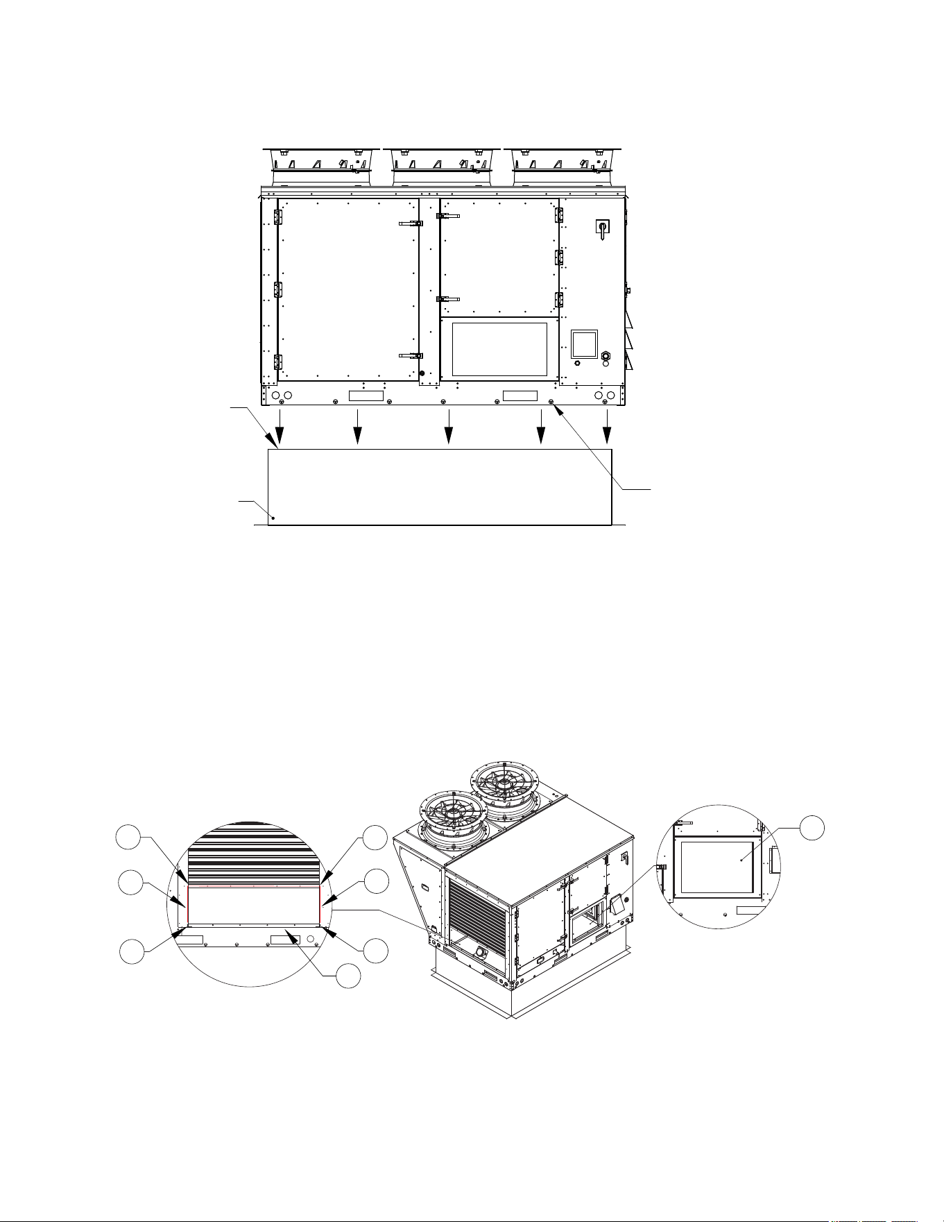
Figure 4 - Curb
Side Return Duct/Access Panel Install, refer to Figure 5 Detail A.
• Install gasket material around the upper and side edges.
• Install ductwork using self-tapping screws.
• Use caulk/sealant around the upper and side edges.
• Do not use caulk/sealant on the lower edge. Use only self-tapping screws to mount ductwork.
Side Discharge Duct Install, refer to Figure 5 Detail B.
• Mount ductwork to the lip of the side discharge opening.
• Use self-tapping screws to secure ductwork.
• Verify the ductwork is clear for opening the top access panel door.
Figure 5 - Side Discharge, Side Return
Curb Attachment
Point
Gasket
Curb
1. Discharge Outlet
2. Upper Edge - Use gasket/sealant for side
return duct or access panel.
3. Side Edges - Use gasket/sealant for side
return duct or access panel.
4. Damper Drain Holes - DO NOT COVER .
5. Lower Edge - DO NOT USE gasket/sealant.
5
1
2
2
3
3
Detail BDetail
A
4
4
11
Duct Hanger Dimensions
Figure 6 provides details for standard curbs, and Figure 7 provides details for ERV curbs. Refer to Table
3 and Table 4 on page 12 for Bill of Materials and curb dimensions.
Use 1/4”-20 x 5/8” Phillips pan head screws and nuts when assembling duct hangers, refer to Figure 8 on
page 12.
Figure 6 - Standard Curb
Figure 7 - ERV Curb
E
D
B
C
F
1
1
2
3
2
3
A
G
INTAKE
END
RETURN
DISCHARGE
ENERGY RECOVERY
VENTILATOR END
RETURN
DISCHARGE
F
D
C
B
A
G
E
H
1
1
2
3
2
3
12
Figure 8 - Duct Hanger Assembled
Table 3 - Duct Hanger Bill of Materials
Ref Size 1 Size 2 Size 3 Size 4
1
RTU1DHR = Quantity x 1 RTU2DHR = Quantity x 2 RTU3DHR = Quantity x 1
N/A
2
RTU1DHL = Quantity x 3
RTU2DHL = Quantity x 3
NOTE: ERV Quantity x 4
RTU3DHL = Quantity x 3
NOTE: ERV Quantity x 4
RTU4DHL = Quantity x 3
NOTE: ERV Quantity x 4
3
RTU1DHD = Quantity x 2 RTU2DHD = Quantity x 2 RTU3DHD = Quantity x 2 RTU4DHD = Quantity x 2
Table 4 - Duct Hanger Curb Dimensions
Reference Size 1 Size 2 Size 2 ERV Size 3 Size 3 ERV Size 4 Size 4 ERV
A 12-3/4” 12-1/4” 18” 16-5/8” 17-7/8” 15-1/2” 15-5/8”
B 36-1/4” 33-3/8” 40-1/4” 48-1/8” 41-3/8” 60-1/4” 49-3/8”
C 59-1/4” 55-1/2” 60-1/4” 71-5/8” 72” 93-3/4” 93-7/8”
D N/A 1-3/4” 73-7/8” N/A 90” N/A 110”
E 31-1/4” 39-1/2” 1-3/4” 48-3/8” N/A N/A N/A
F 5-1/4” 3-3/8” 39-1/2” 2-3/4” 40-3/8” 29-3/8” N/A
G 27-3/4” 35-3/8” 7-3/8” 43-1/2” 2-5/8” 70-3/4” 29-3/8”
H N/A N/A 29-1/8” N/A 43-1/2” N/A 70-7/8”
Non ERV Curb ERV Curb
13
Curb and Adapter
Figure 9 provides details when mounting return and supply duct adapters to an RTU curb.
Figure 9 - Curb and Adapter Details
Secure Return Duct
Adapter to Inside Curb
Flange & Duct Hangers
Secure Supply Duct Adapter to
Inside Flange of Duct Hangers
1
Curb Length
Curb Width
2
6
5
4
5
3
2
6
1. Standard RTU Curb
2. Duct Hangers
3. Return Duct Adapter
4. Supply Duct Adapter
5. Gasket
6. 1/4”-20 x 3/4” Self Drilling Screws
NOTE: Adapters provided by manufacturer are
insulated with R6 panels. It is recommended
adapters by others are insulated with R6 to prevent
condensation from forming around ductwork.
14
Supply Duct Pad Mount Clearances
When a unit will be pad mounted, refer to Figure 10 for details on installation. Always verify the distance
from the wall(s) to the unit. For the supply side of the unit, there must be adequate distance between the
door and duct to service components.
The minimum unsupported distance for vertical ductwork is 20’. Anything over 20’ requires a wall support
bracket. 40’ of vertical ductwork requires two wall support brackets, 60’ would require three wall supports,
etc.
A saddle support is required for horizontal duct runs. Center the saddle support to prevent stress on
connections. Additional saddle supports are recommended every 15’.
Figure 10 - Supply Duct Installation Details
1. RTU Unit
2. RTU Stand
3. Saddle Support
4. Double Wall Supply Duct
5. Interior Space
6. Exterior Wall
7. Adjustable Duct (Recommended)
8. Closure Plate (Inside/Outside)
9. Wall Support Bracket - Required for vertical
ductwork lengths over 20’.
10. Double Wall Return Duct
11. Discharge Adapter - Verify the adapter is
installed properly. The door above should be
able to open without any interference.
A. Door Opening Distance:
• Size 1 = 24-1/2”
• Size 2/3 = 25- 1/2”
• Size 4 = 48-1/2”
B. Adapter Height = 24”
C. Minimum Unsupported Distance = 10’
D. Minimum Exterior Duct Penetration = 4”
E. Horizontal Support Recommended = Every 15’
for Single Wall, every 8’ for Double Wall
F. Minimum Distance Unit to Wall (Supply Side)
• Size 1 = 62”
• Size 2/3 = 70”
• Size 4 = 98”
G. Minimum Distance Unit to Wall (Return Side)
• Size 1 = 62”
• Size 2/3 = 70”
• Size 4 = 98”
1
2
3
4
5
7
8
4
9
A
B
F
C
D
F
A
B
10
5
3
3
E
D
D
G
6
6
11
11
15
Duct Static Pressure Control
Units equipped with an Electrically Controlled Motors (ECMs) or Variable Frequency Drives (VFDs) driven
supply fan, the duct static pressure control option can be used to monitor duct pressure.
1. Locate where the pressure transducer is installed in the control cabinet.
2. Install the static pitot tube in a straight section of ductwork where the airflow is laminar and consistent.
3. Connect the high side tubing to the static pitot tube.
4. Route the tubing through the bottom of the unit to the high side port on the pressure transducer.
5. The low side pressure tubing will be connected to a brass port, located by the control cabinet doors.
This will be connected from the factory.
Figure 11 - Duct Static Pressure Control Details
Airflow from
Supply Fan
Pressure Transducer
Located in Control Cabinet
Ductwork
Low Side
Pressure Tubing
To Brass Port Located by Control
Cabinet Doors.
Static Pitot Tube
High Side
Pressure Tubing
16
Typical Submittal Drawing
17
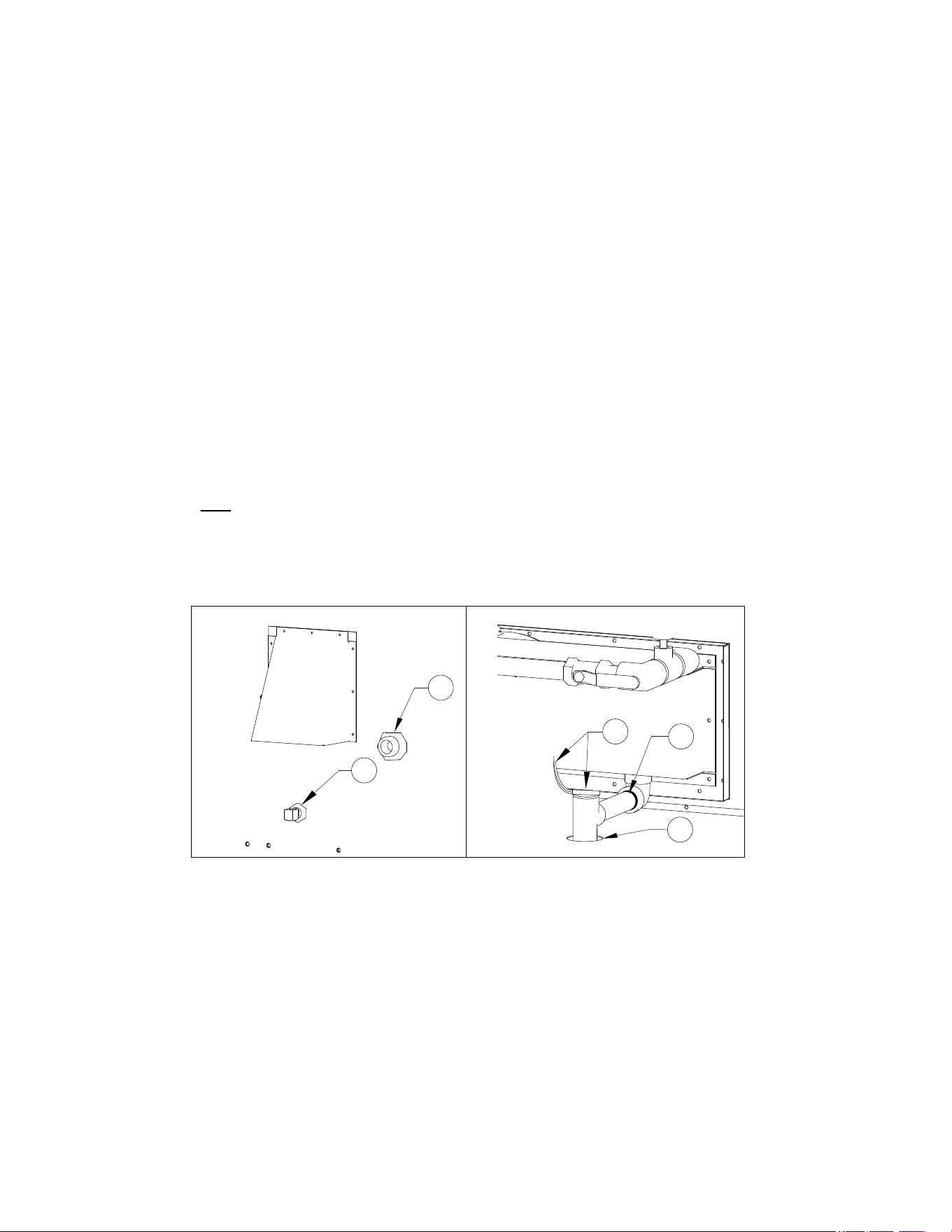
Furnace Condensation Drain
In some applications, condensation can form in the flue collection box, especially when furnaces are
located downstream of cooling coils or operate in a high-efficiency range. If condensation occurs in the flue
collection box, there are fittings in the bottom of the flue collection box to drain condensation out of the box.
The burner in the unit is provided with a condensation drain assembly located underneath this fitting for the
condensation to collect. The drain will need to be connected to field piping to handle the condensation
properly.
Consult your local code as to the proper drainage regulations of the condensation. A heated drain option is
available to prevent the internal drain piping from freezing. If drains are field piped, ensure that the field
piping is piped in a fashion to prevent the condensation from freezing. Do not plug the holes under any
circumstance as it will cause the burners to overflow.
The standard efficiency furnace drain (Figure 12, detail A) is piped to the exterior of the unit via 5/16”
silicone tubing. A 1/4” female NPT fitting is provided external to the unit to allow for field piping if required.
If piping is added to the unit, freeze protection should be added to prevent damage to the field-installed
piping.
The high-efficiency furnace drain (Figure 12, detail B) is fitted with a condensation float switch assembly,
located in the bottom main cabinet, from the factory. A condensation drain must be field piped through the
base of the unit using 3/4” PVC schedule 80 smooth fittings per the above requirements. A 2” deep trap
must be field installed downstream of the unit to ensure adequate flow.
NOTE: Seal ALL
base penetrations with appropriate filler (caulk or all-purpose putty) to prevent
water from entering the space.
Figure 12 - Condensation Drain(s)
To test the factory-installed condensation float switch assembly:
• Turn the unit on, start the heating system. If the heating system does not run, verify the condensation
float switch assembly wiring is correct.
• Remove the condensation float switch from the assembly. Lift the switching arm with a screwdriver.
The heating system should shut off immediately. If not, check that the condensation float switch
assembly’s wiring connections are secure and tight. Re-check the float switch for proper operation.
1. Standard efficiency drain connection. 1/4” NPT trap recommended.
2. 1/2”, 3/4”, or 1” NPT gas connection depending on furnace size.
3. Factory-installed high-efficiency condensation float switch assembly and wiring.
4. High-efficiency drain connection. 3/4” PVC schedule 80.
5. After drain pipe installation, seal base penetrations with an appropriate filler.
Standard Efficiency Drain - Detail A High-Efficiency Drain - Detail B
1
2
3
4
5
18
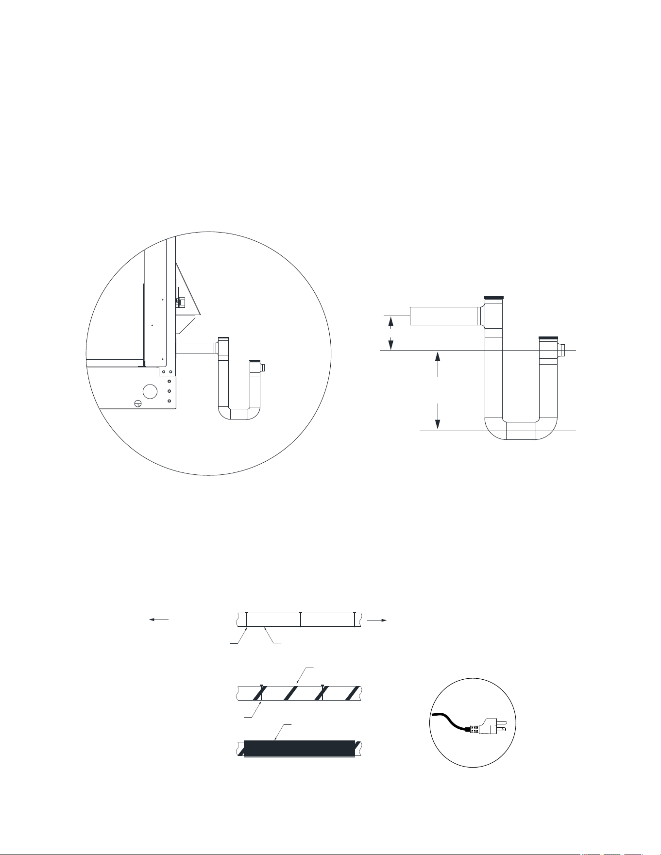
Cooling Coil Trap
There is a field plumbing connection that is required for the DX/cooling coil. This connection is for the drain
pan located under the DX/cooling coil. Also, it is recommended that all plumbing connections be sealed
with Teflon tape or pipe dope.
Install Condensate Trap Assembly to 1” threaded drain pan connection. Use low-profile couplings and 1”
PVC piping to connect on-site drainage to the Condensate Trap Assembly. DO NOT USE UNIONS. The
Condensate Trap Assembly is important for two reasons. First, it will allow drainage to be piped to the most
convenient area. Second, it will keep air from being drawn into the system, impeding drainage. The top lids
of the Condensate Trap Assembly should be removable to allow for cleaning of the trap.
Figure 13 - Condensate Trap Assembly Details
Heat Drain Kit
Units equipped with the Extreme Low Ambient option will include 50 feet of self-regulated heated cable.
The heated cable will ship loose, and will need to be field-wired. The entire length of pipe exposed to
ambient air should be wrapped in heated cable and insulated with foam pipe insulation, starting from the
drain pan nipple and including the condensate drain assembly. The cable should run along the length of
the pipe to be heated. If the cable is longer than the pipe, then the cable can be spiraled along the length of
the pipe. The heat cable should be installed with zip ties. Wiring will be the responsibility of the installer.
Figure 14 - Heated Drain Kit Details
Minimum 1"
4” Trap Height
Condensate Trap
Spiral the heated cable along the pipe
if the length of the cable is too long
To Drainage Area
Field connected
to 120V outlet
Foam Pipe Insulation
Heated cable mounted long bottom of the pipe
Zip Tie
Zip Tie

19
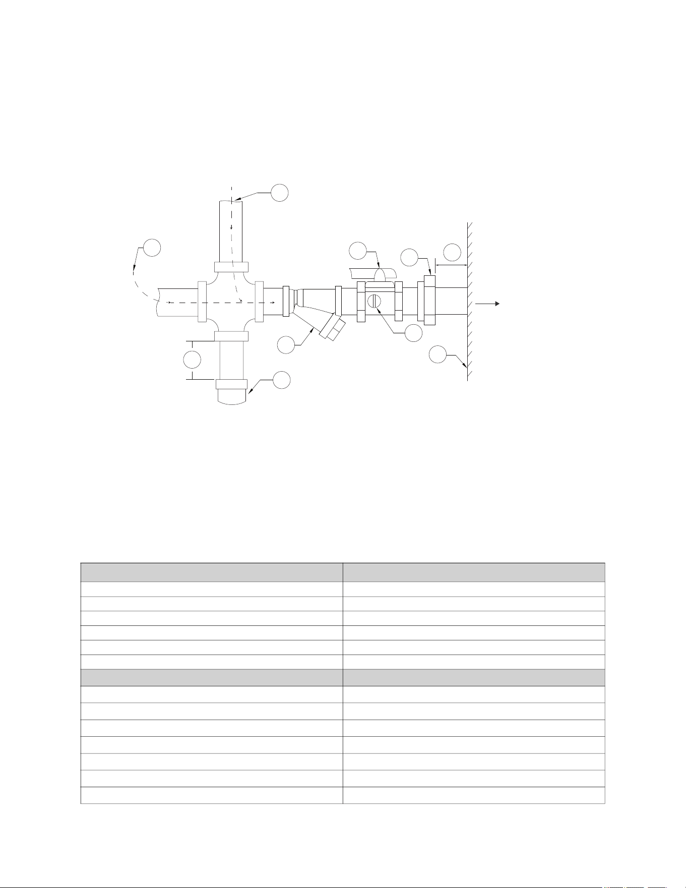
Gas
Installation of gas piping must conform with local building codes, or in the absence of local codes to the
National Fuel Gas Code, ANSI Z223.1 (NFPA 54) – latest edition. In Canada, installation must be in
accordance with CAN/CGA-B149.1 for natural gas units and CAN/CGA-B149.2 for propane units.
WARNING: Inlet gas pressure must not exceed pressure indicated on nameplate. See unit
nameplate for proper gas supply pressure and gas type.
1. Always disconnect power before working on or near a heater. Lock and tag the disconnect
switch and/or breaker to prevent accidental power-up.
2. Piping to the unit should conform to local and national requirements for type and volume of gas
handled, and pressure drop allowed in the line. Refer to the Gas Engineer’s Handbook for gas line
capacities.
3. The incoming pipe near the heater should be sized to match the connection on the outside of the unit.
Connection size is 1/2”, 3/4”, or 1” NPT depending on furnace size. See “Condensation Drain(s)”
Detail A on page 13. Verify unit inlet size to job-specific sheet. Avoid multiple taps in the gas supply,
so the unit always has a steady supply of gas.
4. Install a ground joint union with brass seat and a manual shut-off valve external to the unit casing.
Install shut-off valve adjacent to the unit for emergency shut-off and easy servicing of controls. See
Figure 15 on page 20.
5. Provide a sediment trap, as shown in Figure 15, before each unit and where low spots in the pipeline
cannot be avoided.
6. A minimum 1/8” NPT plugged tapping, accessible for test gauge connection, must be installed
immediately upstream of the gas supply connection to the appliance.
7. Clean out the gas line to remove debris before making connections. Purge line to remove air before
attempting to start unit. Purging air from gas lines should be performed as described in ANSI Z223.1-
latest edition “National Fuel Gas Code,” or in Canada as described in CAN/CGA-B149.
8. All field gas piping must be pressure/leak tested before unit operation. Use a non-corrosive bubble
forming solution or equivalent for leak testing. The heater and its individual shut-off valve must be
disconnected from the gas supply piping system during any pressure testing of that system at test
pressures over 1/2 psi. The heater must be isolated from the gas supply piping system by closing its
individual manual shutoff valve during any pressure testing of the gas supply piping system at test
pressures equal to or less than 1/2 psi.
9. This unit requires a constant 7” water column (wc) minimum for natural gas supply (LP 11 in. wc
minimum) when the unit is operating at maximum gas flow. If the gas supply exceeds 14” wc, it will
damage the internal valve components. If the gas supply drops below 7” wc (LP 11 in. wc), the heater
may not perform to specifications.
Refer to Table 5 for gas pressure type and pressure rating.
High Turndown Furnace
The high turndown furnace will be divided into two separate furnace assemblies within the same cabinet.
This results in a two stage heat source that can stage up and down to meet demand. Since the furnace is
split unevenly, staging on the smallest will result in significantly higher turndown and greater control over
building conditions. An additional Flame Safety Controller (FSC), safety valve, modulating valve, and high
pressure switch (if equipped) will be installed. See Figure 24 on page 48.
NOTICE
Refer to the heater rating plate for determining the minimum gas supply pressure for obtaining the
maximum gas capacity for which this heater is specified.
20
Strainer
The strainer is used to prevent debris from entering the gas train. New piping must be used. Properly ream
and clean metal burrs. Proper care is needed to ensure that the gas flow is in the same direction as
indicated on the strainer. Do not over-tighten pipe connections. Use pipe dope on male threads only. Install
a drip leg in the gas line in accordance with the Authority Having Jurisdiction (AHJ) guidelines.
Figure 15 - Gas Connection Diagram
Proper clearance must be provided in order to service the strainer. A minimum of a 4” clearance distance
must be provided at the base of the strainer.
Table 5 - Gas Train Details
Gas Pressure Type Gas Pressure
Inlet Pressure - Natural Gas 7 - 14 Inches WC
Inlet Pressure - Propane (LP) 11 - 14 Inches WC
Maximum Manifold Pressure - Natural Gas 3.5 Inches WC Maximum
Maximum Manifold Pressure - Propane (LP) 10 Inches WC Maximum
Minimum Manifold Pressure - Natural Gas 0.15 Inches WC Maximum
Minimum Manifold Pressure - Propane (LP) 0.75 Inches WC Maximum
Strainer Size
4417K64 3/4”
4417K65 1”
4417K66 1-1/4”
4417K67 1-1/2”
4417K68 2”
4417K69 2-1/2”
4417K71 3”
1. Gas Supply Line Connection
2. Manual Gas Shut-off Valve
3. Plugged 1/8” NPT Test Gauge Connection
4. Ground Joint Union with Brass Seat
5. Sediment Trap
6. Strainer
7. Unit
A. Minimum Depth = 6”
B. Maximum Length = 12”
4
1
1
3
A
5
6
2
B
To Unit
Gas Manifold
7
21
High Altitude and Gas Type Orifice Sizing
The burner orifices should be sized per Table 6 and Table 7, depending on fuel type, furnace size, and
altitude. Standard orifice sizes are for sea level. The unit should be ordered with the altitude specific
orifices, or the parts should be ordered through the manufacturer (Table 8 on page 22). Refer to main gas
valve documentation for instructions to convert gas valve spring from Natural to LP and vice versa.
NOTE: 50,000 – 100,000 BTU High-Efficiency Natural Gas furnaces use 2.3mm Drill Size at 0 – 3999
ft. Follow charts for all other altitudes.
Table 6 - Natural Gas High Altitude Charts
Natural Gas High Altitude Conversion
Size 3 Size 2 and 3 Size 1, 2, and 3
High Altitude for 500,000
BTU
High Altitude for 400,000
BTU
High Altitude for 300,000 to 50,000
BTU
Altitude
(Feet)
Input Rate Drill Size Input Rate Drill Size Input Rate Input Rate Input Rate Drill Size
0 - 1,999 500,000 #33 400,000 #41 300,000 200,000 150,000 #3/32
2,000 - 2,999 479,998 #35 384,000 #42 288,000 192,000 144,000 2.35mm
3,000 - 3,999 460,797 #35 368,640 2.35mm 276,480 184,320 138,240 2.3mm
4,000 - 4,999 442,668 #36 353,894 2.3mm 265,421 176,947 132,710 #43
5,000 - 5,999 424,668 #36 339,739 #43 254,804 169,869 127,402 2.25mm
6,000 - 6,999 407,680 #37 326,149 2.25mm 244,612 163,075 122,306 #44
7,000 - 7,999 391,372 #38 313,103 #44 234,827 156,552 117,414 2.15mm
8,000 - 8,999 375,716 #38 300,579 #45 225,434 150,290 112,717 #46
9,000 - 10,000 360,686 #40 288,556 #46 216,417 144,278 108,209 #47
Natural Gas High Altitude Conversion
Size 4 Size 4
High Altitude for 600,000 BTU High Altitude for 500,000 to 200,000 BTU
Altitude
(Feet)
Input Rate Drill Size Input Rate Input Rate Input Rate Input Rate Drill Size
0 - 1,999 600,000 3.4mm 500,000 400,000 300,000 200,000 3.3mm
2,000 - 2,999 576,000 #30 479,998 384,000 288,000 192,000 #30
3,000 - 3,999 552,960 #30 460,797 368,640 276,480 184,320 #31
4,000 - 4,999 530,482 #30 442,668 353,894 265,421 176,947 #31
5,000 - 5,999 509,608 #30 424,668 339,739 254,804 169,869 #31
6,000 - 6,999 489,224 #30 407,680 326,149 244,612 163,075 #31
7,000 - 7,999 469,654 #31 391,372 313,103 234,827 156,552 #32
8,000 - 8,999 450,868 #31 375,716 300,579 225,434 150,290 #32
9,000 - 10,000 432,834 #32 360,686 288,556 216,417 144,278 #33
22
Table 7 - LP Gas High Altitude Charts
LP Gas High Altitude Conversion
Size 3 Size 2 and 3 Size 1, 2, and 3
High Altitude for 500,000
BTU
High Altitude for 400,000
BTU
High Altitude for 300,000 to 50,000 BTU
Altitude
(Feet)
Input Rate Drill Size Input Rate Drill Size Input Rate Input Rate Input Rate Drill Size
0 - 1,999 500,000 1/16” 400,000 1.45mm 300,000 200,000 150,000 #54
2,000 - 2,999 479,998 #53 384,000 #54 288,000 192,000 144,000 #54
3,000 - 3,999 460,797 #54 368,640 #54 276,480 184,320 138,240 #55
4,000 - 4,999 442,668 #54 353,894 #54 265,421 176,947 132,710 #55
5,000 - 5,999 424,668 #54 339,739 #54 254,804 169,869 127,402 #55
6,000 - 6,999 407,680 #54 326,149 #55 244,612 163,075 122,306 #55
7,000 - 7,999 391,372 #54 313,103 #55 234,827 156,552 117,414 #56
8,000 - 8,999 375,716 #55 300,579 #55 225,434 150,290 112,717 #56
9,000 - 10,000 360,686 #55 288,556 #56 216,417 144,278 108,209 #57
LP Gas High Altitude Conversion
Size 4 Size 4
High Altitude for 600,000 BTU High Altitude for 500,000 to 200,000 BTU
Altitude
(Feet)
Input Rate Drill Size Input Rate Input Rate Input Rate Input Rate Drill Size
0 - 1,999 600,000 #45 500,000 400,000 300,000 200,000 #45
2,000 - 2,999 576,000 #46 479,998 384,000 288,000 192,000 #46
3,000 - 3,999 552,960 #47 460,797 368,640 276,480 184,320 #47
4,000 - 4,999 530,482 #47 442,668 353,894 265,421 176,947 #47
5,000 - 5,999 509,608 #47 424,668 339,739 254,804 169,869 #47
6,000 - 6,999 489,224 #48 407,680 326,149 244,612 163,075 #48
7,000 - 7,999 469,654 #48 391,372 313,103 234,827 156,552 #48
8,000 - 8,999 450,868 #49 375,716 300,579 225,434 150,290 #49
9,000 - 10,000 432,834 #49 360,686 288,556 216,417 144,278 #49
Table 8 - Orifice Part Numbers and Quantity Charts
Orifice Part Numbers Orifice Quantity per Furnace
Size Part # AX # Size Part # AX # Size 1, 2, and 3 Qty Size 4 Qty
#30 BG100-30 A0029277 #49 BG100-49 A0029283 50,000 BTU 2 N/A
-
#31 BG100-31 A0029278 #50 BG100-50 A0029284 75,000 BTU 3 N/A
-
#32 BG100-32 A0029279 #53 BG100-53 A0030724 100,000 BTU 4 N/A
-
#33 BG100-33 A0029280 #54 BG100-54 A0023048 125,000 BTU 5 N/A
-
#35 BG100-35 A0029281 #55 BG100-55 A0023049 150,000 BTU 6 N/A
-
#36 BG100-36 A0030719 #56 BG100-56 A0023057 200,000 BTU 8 200,000 BTU
4
#37 BG100-37 A0030721 #57 BG100-57 A0028803 300,000 BTU 12 300,000 BTU
6
#38 BG100-38 A0030722 1/16” BG100-116 A0030725 400,000 BTU 15 400,000 BTU
8
#40 BG100-40 A0030723 1.45mm BG101-16 A0023052 500,000 BTU 15 500,000 BTU
10
#41 BG100-41 A0023045 2.15mm BG101-21 A0023055 N/A - 600,000 BTU
11
#42 BG100-42 A0023050 2.25mm BG101-20 A0023054
#43 BG100-43 A0023047 2.3mm BG101-05 A0023051
#44 BG100-44 A0023046 2.35mm BG101-19 A0023053
#45 BG100-45 A0028800 3.3mm BG101-08 A0029285
#46 BG100-46 A0028801 3.4mm BG101-09 A0030726
#47 BG100-47 A0028802 #3/32 BG101-3/32 A0023044
#48 BG100-48 A0029282
23
LP Conversion Kit for RTU Series
LP/Natural Gas conversion kits are used to convert from one gas type to another in the field. This kit is
used on all RTUs, and the part numbers in Table 9 should be used on furnace sizes listed.
Kits contain:
• Main Safety Gas Valve Regulator Spring
• Furnace orifices marked with orifice size
This unit is configured for the gas type listed on the nameplate. To convert gas types, you must use the
following parts listed in Table 9. The size-specific parts include the orifice conversion parts and the
combination gas valve spring(s). These parts are available by contacting the Parts & Service Department
at 1 (866) 784-6900. All field gas piping must be pressure/leak tested before unit operation. Use a
noncorrosive bubble forming solution or equivalent for leak testing. The equipment and its individual shut-
off valve must be disconnected from the gas supply piping system during any pressure testing of that
system at test pressures in excess of 1/2 psi. The equipment must be isolated from the gas supply piping
system by closing its individual manual shutoff valve during any pressure testing of the gas supply piping
system at test pressures equal to or less than 1/2 psi. This must be performed on an annual basis.
Table 9 - Gas Conversion Kit Part Numbers
Size 1 Units
Furnace Size 50 MBH 75 MBH 100 MBH 125 MBH 150 MBH 200 MBH
Natural Gas NAT-HMG50 NAT-HMG75 NAT-HMG100 NAT-HMG125 NAT-HMG150 NAT-HMG200
LP Gas LP-HMG50 LP-HMG75 LP-HMG100 LP-HMG125 LP-HMG150 LP-HMG200
Modulating Valve E50-1/2”
Size 2 and 3 Units
Furnace Size 50 MBH 100 MBH 150 MBH 200 MBH 250 MBH 300 MBH 400 MBH 500 MBH
Natural Gas NAT-HMG50 NAT-HMG100 NAT-HMG150 NAT-HMG200 NAT-HMG250 NAT-HMG300 NAT-HMG400 NAT-HMG500
LP Gas LP-HMG50 LP-HMG100 LP-HMG150 LP-HMG200 LP-HMG250 LP-HMG300 LP-HMG400 LP-HMG500
Modulating Valve E50-3/4” E60-1”
Size 4 Units
Furnace Size 200 MBH 300 MBH 400 MBH 500 MBH 600 MBH
Natural Gas NAT-HMA200 NAT-HMA300 NAT-HMA400 NAT-HMA500 NAT-HMA600
LP Gas LP-HMA200 LP-HMA300 LP-HMA400 LP-HMA500 LP-HMA600
Modulating Valve E50-3/4” E60-1”

24
Pre-Conversion Unit Check-Out
The following procedure is intended as a guide to aid in determining that the appliance is properly installed
and is in a safe condition for continuing use. It should be recognized that generalized test procedures
cannot anticipate all situations. Accordingly, in some cases, deviation from this procedure may be
necessary to determine safe operation of the equipment:
• This procedure should be performed before any attempt at modification of the appliance or the
installation.
• If it is determined there is a condition that could result in unsafe operation, the appliance should be
shut off, and the owner advised of the unsafe condition.
Follow these steps when making a safety inspection:
1. Conduct a gas leakage test of the appliance piping and control system downstream of the shut-off
valve in the supply line to the appliance.
2. Visually inspect the venting system for proper size and horizontal pitch and determine there is no
blockage or restrictions, leakage, corrosion, or other deficiencies that could cause an unsafe condition.
3. Shut off all gas to the appliance and shut off any other fuel-burning appliance within the same room.
Use the shut-off valve in the supply line to each appliance.
4. Inspect burners and crossovers for blockage and corrosion.
5. Inspect heat exchangers for cracks, openings, or excessive corrosion.
6. Insofar as is practical, close all windows and all doors between the space where the appliance is
located and other spaces of the building. Turn on any exhaust fans so that they will operate at
maximum speed. If it is believed sufficient combustion air is not available, refer to the section covering
air for combustion, venting, and ventilation of Natural Gas and Propane Installation Code, CSA
B149.1, or National Fuel Gas Code, ANSI Z223.1/NFPA 54, for guidance.
7. Place the appliance in operation following the lighting instructions. Adjust thermostat so the appliance
will operate continuously. Other fuel-burning appliances shall be placed in operation.
8. Determine that the pilot is properly burning and that the main burner ignition is satisfactory by
interrupting and re-establishing the electrical supply to the appliance in any convenient manner.
• Visually determine that main burner gas is burning properly, i.e. no floating, lifting, or flashback.
Adjust the primary air shutter(s) as required.
• If the appliance is equipped with high- and low-flame control or flame modulation, check the main
burner for proper operation at low flame.
9. Test for spillage at the draft hood relief opening after 5 minutes of main burner operation. Use a draft
gauge, the flame of a match, or candle.
10. Return doors, windows, exhaust fans, and all other fuel-burning appliances to their previous conditions
of use.
11. Check both limit control and fan control for proper operation. Limit control operation can be checked by
temporarily disconnecting the electrical supply to the supply motor and determining that the limit
control acts to shut off the main burner gas.
25
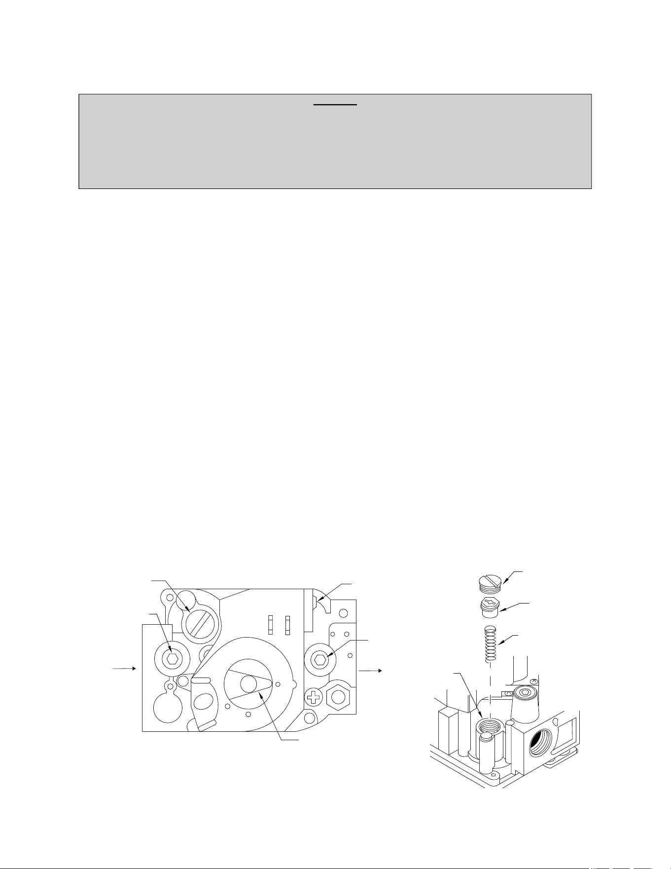
Gas Conversion Instruction
Follow the below steps when converting gas types, refer to Figure 16 for details:
1. Before proceeding with the conversion, shut off all gas supply to the unit at the manual shut-off valve.
2. Disconnect or shut off all electrical power to the unit.
3. Turn the thermostat to the lowest temperature setting.
4. Remove screws holding manifold pipe assembly to burner assembly.
5. Loosen and remove natural gas orifices, remove from manifold.
6. Install propane gas orifices provided with kit. Verify orifice sizes are correct.
7. Open Gas Valve Regulator conversion kit and follow instructions provided for conversion of gas valve
regulator. Make sure to apply the label provided in the kit indicating that the valve has been
converted. The spring tension is different for LP and Natural Gas. This is the main component
difference.
8. Secure manifold assembly to burner assembly. Check that all orifices are aligned with the opening on
each burner.
9. Turn on gas supply at manual shut-off valve.
10. Leak check union fitting and connection at gas valve using a soap solution.
11. Turn power to the unit “On.”
12. Initiate a heating cycle. Check inlet and manifold gas pressures.
13. A label is included in this kit to attach to the manifold indicating this assembly has been converted to
LP gas.
14. Attach label to manifold where it is readily visible when this assembly is accessed for service.
15. Verify proper sequence of operation for appliance after conversion is completed.
16. Verify proper gas inlet supply pressure and information on maximum and minimum supply pressures.
Figure 16 - Gas Valve(s)
Warning
This conversion kit shall be installed by a qualified service agency in accordance with the
manufacturer’s instructions and all applicable codes and requirements of the authority having
jurisdiction. If the information in these instructions is not followed exactly, a fire, explosion or
production of carbon monoxide may result causing property damage, personal injury or loss of
life. The qualified service agency performing this work assumes the responsibility for the proper
conversion of the appliance with this kit.
Inlet
Inlet
Pressure Tap
Pressure Regulator Adjustment
(Under Cap)
Wiring
Terminals (2)
Outlet
Outlet
Pressure Tap
Gas Control
Knob
On/Off Gas Valve
Cap Screw
- LP Gas = Black
- Natural = Silver
Pressure
Regulator
Adjusting Screw
Spring
- LP Gas = Red
- Natural = Stainless
Steel
Pressure Regulator
Housing
Modulating Gas Valve
26
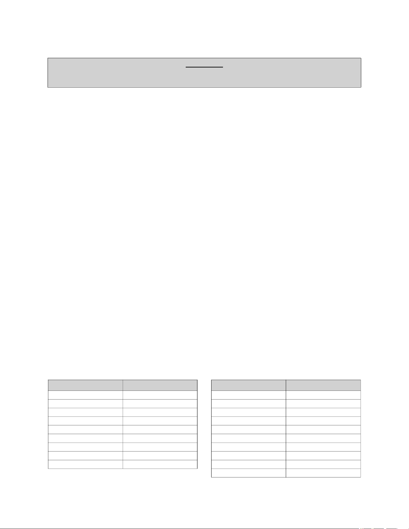
Electrical
Before connecting power to the unit, read and understand the entire section of this document. As-built
wiring diagrams are furnished with each control by the factory and are attached to the module’s door.
When installed, the appliance must be electrically grounded in accordance with local codes, or in
the absence of local codes, with the National Electrical Code, ANSI/NFPA 70, and/or the Canadian
Electrical Code, CSA C22.1, if an external electrical source is utilized. Verify the voltage and phase of
the power supply, and the wire amperage capacity is in accordance with the unit nameplate. Refer to
Table 10 for wire size and amperage ratings.
• Always disconnect power before working on or near a unit. Lock and tag the disconnect switch
and/or breaker to prevent accidental power-up.
• The main electrical feed should be brought through one of the conduit openings located in the base of
the unit, within the perimeter of the curb. When installing wiring and conduit, make sure to route in front
of the gas train. DO NOT ROUTE WIRING WITHIN THE SUPPLY OR RETURN DUCT. KEEP
WIRING AND CONDUIT AT LEAST 1” AWAY FROM THE BURNER EXHAUST VENT. Refer to
Figure 17 on page 27.
• A dedicated branch circuit should supply the unit with short circuit protection according to the National
Electric Code.
• Make certain that the power source is compatible with the requirements of your equipment. The unit
nameplate identifies the proper phase and voltage of the equipment.
• Units shipped with an optional remote HMI panel have separate wiring requirements. It is important to
run the main electrical wires in a separate conduit from the remote control HMI wiring. The HMI wiring
is Cat-5 and must be separate from power cable. Maximum distance on any low voltage wire is 1000
feet.
• Before connecting the unit to the building power source, verify power line wiring is de-energized.
• Secure the power cables to prevent contact with sharp objects.
• Do not kink power cable and never allow the cable to come in contact with oil, grease, hot surfaces, or
chemicals.
• Before powering up the unit, check fan wheel for free rotation and make sure that the interior of the
heater is free of loose debris or shipping materials.
• If any of the original wire supplied with the appliance needs to be replaced, it must be replaced with
wiring material having a temperature rating of at least 149°F and type TW wire or equivalent.
• Seal ALL base penetrations with an appropriate filler (caulk or all-purpose putty) to prevent
water from entering the space. Refer to Figure 17.
WARNING: Low Voltage Wiring Should Never Route Together With High Voltage Wiring.
WARNING!!
Disconnect power before installing or servicing control. High voltage electrical input is needed
for this equipment. A qualified electrician should perform this work.
Table 10 - Copper Wire Ampacity
Wire Size Maximum Amps Wire Size Maximum Amps
14 AWG 15 1/0 AWG 150
12 AWG 20 2/0 AWG 175
10 AWG 30 3/0 AWG 200
8 AWG 50 4/0 AWG 230
6 AWG 65 250 MCM 255
4 AWG 85 300 MCM 285
3 AWG 100 350 MCM 310
2 AWG 115 400 MCM 335
1 AWG 130 500 MCM 380
600 MCM 420
27
Building to Unit Power Wiring Connection
Figure 17 - Conduit Termination/Disconnect Switch Wiring
Site Preparation – Controls
• Consider general service and installation space when locating the remote temperature control.
• Locate the control as close to the space/fan that it will serve to reduce long, unnecessary wire runs.
• Install thermostats in locations that will produce a good representation of the air being moved by the
fan in the space. Avoid thermostat installations in direct sunlight, near HVAC supplies, or abnormal
temperature airstreams.
BKBKBKBK BKBK
GR
208/460/600 V 3 PH.
Size 3 Unit Shown
Safety
Disconnect
Switch
Main Power to Unit’s
Safety Disconnect
Switch from Building
Breaker
Run Conduit
to First Shelf
After Wiring Installation is
Complete, Seal All Base
Penetrations with
Appropriate Filler
Safety
Disconnect
Switch
Gal-flex
Conduit
Field
Supplied
Wiring
Fused Disconnect Option
Fused Disconnect Options
250V
480/600V
Size
30A
60A
100A
DG321NRB
DG322NRB
DG323NRB
DG321NRB
DG322NRB
DG323NRB
1
1, 2, 3
1, 2, 3
WARNING: KEEP WIRING
AND CONDUIT AT LEAST
1” AWAY FROM THE
BURNER EXHAUST VENT.
28
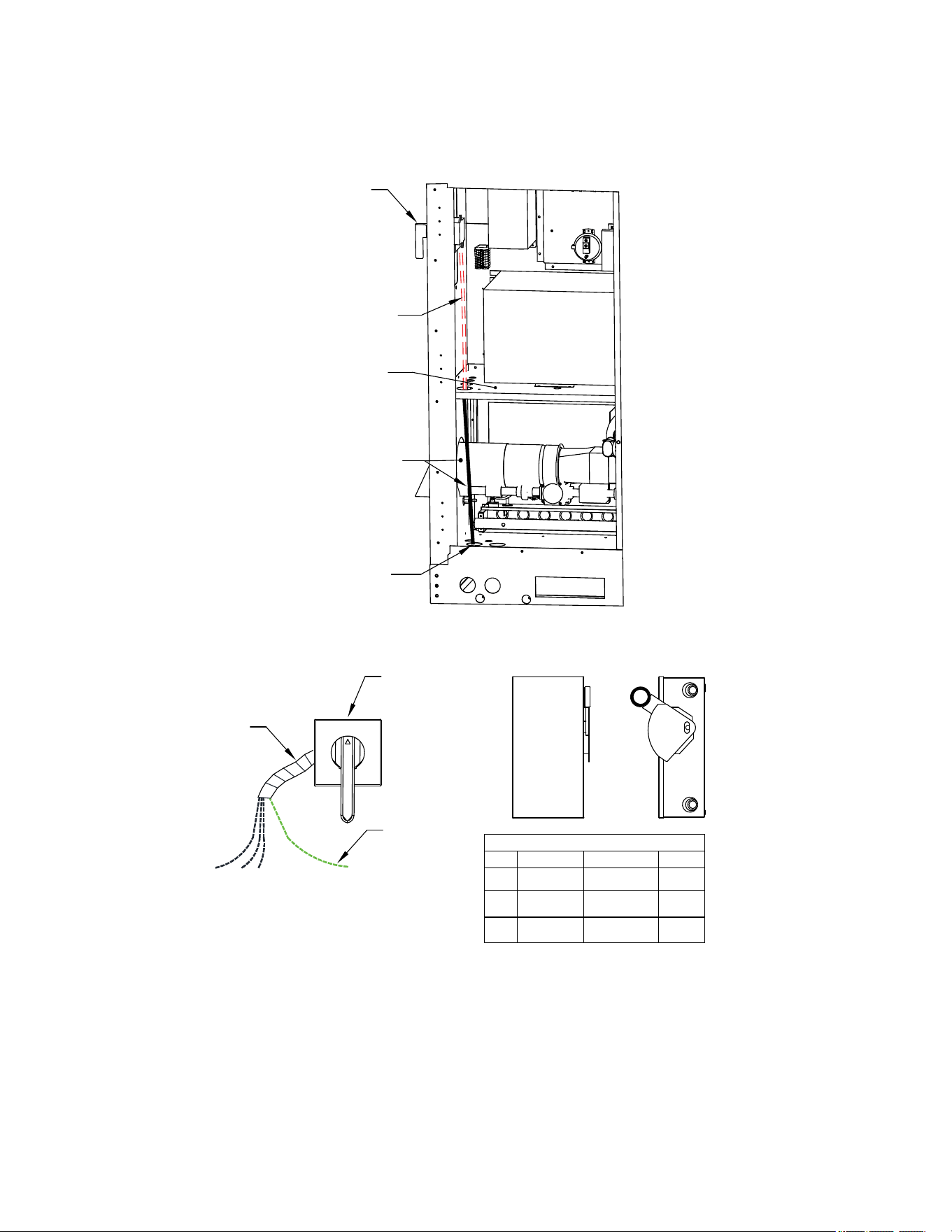
HMI and Remote Room Sensor Installation
Remote HMI faceplates (Figure 18), remote room sensors (Figure 19), and smart controls may be
ordered and shipped separately. These components measure temperature and assist in controlling the
unit. These components should be installed in a safe location, free of influence from external heat sources.
Install sensors in areas indicative of the average room temperature. Keep sensor away from heat-
producing appliances. HMIs and remote room sensors can be installed directly to industry-standard
junction boxes, either surface mounted or recessed mounted. HMIs have a built-in temperature/relative
humidity (RH) sensor, which is typically used to help control the automatic function of the unit.
The HMI can also be configured to control the unit from a remote location manually. They can be
configured not to use the internal temperature/relative humidity sensor. In this configuration, the sensor in
the HMI is ignored in automatic operation. Multiple HMIs can be connected to one unit for temperature and
R/H averaging. All combination temperature/humidity HMIs will use a vented standoff. Mount the static
pressure tube close to the HMI to obtain proper room conditions.
A max of 4 additional HMIs can be daisy-chained together. Place an End-of-Line (EOL) device in the last
HMI connected.
Figure 18 - HMI with Standoff
Figure 19 - Remote Room Sensor
The room temperature sensor is a 10K ohm thermistor. The
sensor provides constant room temperature to the controller.
It should be installed on a wall somewhere in the room, but
not directly in the HVAC diffuser’s path or close to heat-
producing appliances so that the reading is not affected by
heat.
Room sensors are not required for proper control operation,
but still can be configured as remote sensors or averaging
sensors.
Do not install the room sensor on the ceiling
.
5-1/2”
5-1/2”
J-Box
HMI Standoff
HMI with Built-in
Temperature/Humidity
Sensor
Static Pressure Tube
Connected to the High Pressure
Port on Pressure Sensor
Cat 5 Connection
J1 on HMI-1 to J2 on HMI-2
Route the provided 1/4” nylon
tubing close to the HMI in the
space.
29
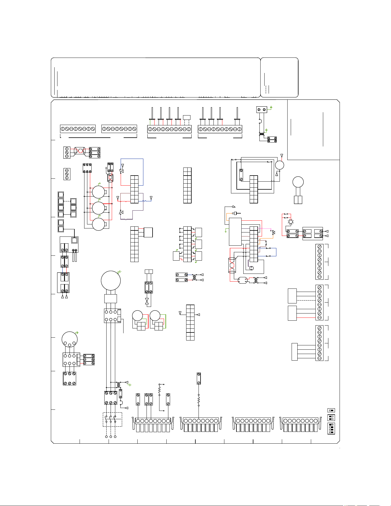
Typical Wiring Schematic
A B C D E F G H I
1
2
3
4
5
6
7
8
9
10
COMPONENT LIST
LABEL DESCRIPTION
J1
8
7
6
5
4
3
2
1
8
7
6
5
4
3
2
1
8
7
6
5
4
3
2
1
8
7
6
5
4
3
2
1
J10 120V
J30 120V
J29 120V
J9 120V
10
1
J15
10
1
J35
123456789
101112131415161718
J7
1
234567
891011121314
J13
1234567
891011121314
J18
2
4
1
3
J34
2
4
1
3
J37
SW-01
BK
12
34
THERMISTORS
THERMISTORS
L
+
-
PWS-02
N
BL
RD
J2 J3 J4 J5 J6
123456789
101112131415161718
123456789
101112131415161718
J31
1
23456789
101112131415161718
J36
1
23456789
101112131415161718
J32
WH
WH
WH
WH
BK
RD
WH
WH
PR
BR
PS-04
C
NO
C
NO
BL
RD
LEGEND
FIELD WIRING
FACTORY WIRING
BK- BLACK
BL- BLUE
BR- BROWN
OR- ORANGE
WH- WHITE
OR/BL- OR/BL STRIPE
BL/RD- BL/RD STRIPE
RD/GN- RD/GN STRIPE
WH/BL- WH/BL STRIPE
YW- YELLOW
GY- GREY
PR- PURPLE
RD- RED
GR- GREEN
PS-10
BK
DM
BK
WH
RD
BL
MT-01
GR
FIRE I/P TRIPS UPON 120VAC
F
BK
PSW
TH
IND
V1
V2
HV
S1
G
R
L
FSC-01
RD
BK
PR
YW
BR
GY
GY RD
TR-03
120
24
VA-05
WH BK
SHD
BK
RD
H
N
PS-01
C
NO
SW-03
STP WIRE
SW-04
BL
BL
BR
BR
PK
J17
PV-01
J21
WH
BK
VA-01
PR
YW
YW
FR-01
IGNITOR
GTO WIRE
N
2x
H
2x
8
AI-4
DI-2
J28
1
AI-3
AI-2
J14
1
8
AI-1
DI-1
J12
1
8
C
R
BAS/STAT
G
Y
W
J16
8
1
J11
8
1
OR
SD-01
24VAC
INPUT
COMMON
PS-10
CLGGD_FILTER_SWITCH
PS-04
LOW_GAS_SWITCH
SUPPLY_MOTOR
MT-01
SW-15
SW-16
OIL SENSOR
SW-17
OIL_SENSOR
SEN-1
LIQUID
LINE
24V
COM
VOUT
LINE
SUCTION
DISCHARGE
LINE
SEN-1
PS-22
PS-21
PS-20
EC1+
EC1-
PS-20
LIQUID_LINE_PRES
SUCTION_LINE_PRES
PS-21
DISCHARGE_LINE_PRES
PS-22
(DX) SW-18
24VAC(O/P)
(I/P)
(DOOR) SW-19
24VAC(O/P)
(I/P)
H
CB-01
N
CIRCUIT_BREAKER
CB-01
FSC-01
FLAME_SAFETY_CTLR
FR-01
FLAME_ROD
MAIN-1
PV-XX
FURNACE_POWER_VENT
MOD-1
POWER_VENT_1
SN-06
SN-07
SN-08
SN-10
SUCTION_LINE
LIQUID_LINE
INDOOR_COIL
COMP_DISCHARGE
24VDC
0-10V IN
COMMON
HUM-1
HUM-2
COMMON
0-10V IN
24VDC
SUPPLY
HG-01
EEV-01
CMT-03
GR
CMT-02
GR
CMT-01
GR
RD
BK
EC1+
EC1-
RD
BK
RD
BK
L1
L2
L3
E1
24VD1
T
L1
L2
L3
E1
24VD1
T
L1
L2
L3
E1
24VD1
T
JUMPJUMPJUMP
VOUT
COM
24V
VOUT
COM
24V
VOUT
COM
24V
CMT-XX
CONDENSING_MTR
INTAKE
RD
BK
SN-01
RD
GR
J33
2
3
1
BC
BP
MT-08
BK
WH
MB+
BK
RD
BK
RD
BK
RD
DISCHARGE
OUTDOOR
RETURN
SN-04
RD
BK
SN-03
RD
BK
SN-02
RD
BK
P1
P2
+
-
H
N
N
1
J25
3
DDC
MODBUS
J38
31
120V
BP
BC
HMI
J2
H
N
BP
BC
RD BL
BK
WH
(40VA)
24V
120V
B1
C1
A1
C2
B2
A2
LR-02
ON
12 3
4
MUA Board
SW-01
DISCONNECT_SWITCH
REFR_LOW_PRES_SW
SW-15
REFR_HIGH_PRES_SW
SW-16
SW-17
REFR_HIGH_TEMP_SW
MOD_GAS_VALVE
VA-05
VA-01
SINGLE_SAFETY_VALVE
HG-01
REHEAT_VALVE_1
ON
S2
12
ON
PROG
1
CAT-5
SCADA
+
-
CM+
CM-
J2
SPACE
HMI
SCADA_COMM_MODULE
SCADA
L3
L2
L1
W
V
U
VFD-02
BK
BK
56
DB-01
L1
L2
L3
DISTRIBUTION_BLOCK
DB-01
L3
L2
L1
TO MODBUS CONVERTER
>=15HP USE RS485
EOL
RJ45
RJ45
T3
T2
T1
VFD-01
TO J4
CAT 5
VFD-01
SUPPLY_FAN_VFD
VFD-02
COMP_VFD
616869
DB-01
L1
L2
L3
CP-01
T3
T2
T1
GR
68
61
69
68
61
69
RD
BK
WH
BK
BK
BK
BK
BK
BK
BK
BK
BK
BK
BK
BK
DB-01
L1
L2
L3
WH
RD
BK
SHIELDED
WIRE
EEV-01
ELEC_EXP_VALVE_1
WH
BK
GR
RD
WH
BK
GR
RD
OR
TR-01
CTRL_TRANSFMR
TR-01
MOD_VALVE_TRFMR_1
TR-03
SW-13
J4
SUPP
LOCAL
VFD
BK
RD
WH
TEMP_SENSOR
SN-XX
BK
RD
WH
BK
RD
WH
BK
HE-03
N
WH
HB
+
+
-
N
PWS-01
-
L
LED2
BK
RD
DS-02DS-02
N HB
DS-03
TR-05
GR GRGR
GR
VIN
VOUT
COM
VIN
VOUT
COM
HUM-4
VIN
VOUT
COM
BK
RD
WH
BK
RD
SHD
GR
RD
BK
WH
BK
BK
BK
BK
BK
BK
RC-01
BK
WH
15A MAX
TR-06
CB-02
L1
L2
BK
BK
ABC
SHIELDED
WIRE
24VAC
9
45
10
C
N.O.
ROLL_OUT_1-1
SW-03
RV1
RV2
BK
WH
2
1
J23
RV-01
HUM-2
+
-
CAB_LED_STRIP
LED-XX
24VDC_POWER_SUPP
PWS-XX
ELEC_DOOR_SWITCH
DS-XX
PS-01
VENT_PROVING_1
LINE/LOAD_REACTOR
LR-XX
FURN_HIGH_TEMP_1-1
SW-04
ROLL_OUT_1-2
SW-13
CRANKCASE_HEATER
HE-03
SW-18
DX_FLOAT_SWITCH
SW-19
DOOR_SWITCH
BOARD_POWER_TRFMR
TR-05
CONV_OUTLET_TRFMR
TR-06
SMOKE_DETECTOR
SD-01
CONV_OUT_BREAKER
CB-02
CONV_OUTLET
RC-01
REVERSING_VALVE
RV-01
MT-08
MB_DAMPER_MTR
HUM-XX
HUM/TEMP_SENSOR
HUM-XX
HUM/TEMP_SENSOR
HUM-XX
INTAKE SPACE
SPACE
RETURN
HE-02
FURNACE_DRAIN_HEATER
HE-02
B4
F4
H8
E4
I8
I8
C9
I8
E5
H7
H8
B6
F8
SW-04
D3
F8
F9
E1
F9
F8
SN-XX
E8
B3
D4
C1
VFD-01
B2
F1
D3
E8
E7
F5
F5
F5
A3
G2
G9/H10
G7
C7
B3
F6
F6
F6
F5
E3
H3
G3
OUTDOOR:1.34HP-380-480V-3P-2.0FLA
OUTDOOR PART:163322
SUPPLY: 7.5HP-460V-3P-9.6FLA
MOTOR INFO
SUPPLY VFD PART: ESV552N04TXB571
COMP:VZH117BG
COMP MOTOR:380-480V-3P-27.2RLA
COMP VFD PART:134F9368
SUPPLY VFD PART: ESV552N04TXB571
REACTOR PART: KDRULA4L
ELECTRICAL INFORMATION
MOTOR/CTRL CIRCUIT MCA: 62.2A
MOTOR/CTRL CIRCUIT MOP: 80A

30
Variable Frequency Drive (VFD)
Consult the VFD manual and all documentation shipped with the unit for proper installation and wiring of
the VFD. The VFD has been programmed by the factory with ordered specific parameters. Use Table 11
as a guide during installation.
Variable Frequency Drive (VFD) Installation
Input AC Power
• Circuit breakers feeding the VFDs are recommended to be thermal-magnetic and fast-acting. They
should be sized based on the VFD amperage and according to Table 12 on page 32. Refer to the
installation schematic for exact breaker sizing.
• Every VFD should receive power from its own breaker. If multiple VFDs are to be combined on the
same breaker, each drive should have its own protection measure (fuses or miniature circuit breaker)
downstream from the breaker.
• Input AC line wires should be routed in conduit from the breaker panel to the drives. AC input power to
multiple VFDs can be run in a single conduit if needed. Do not combine input and output power
cables in the same conduit.
• The VFD should be grounded on the terminal marked PE. A separate insulated ground wire must be
provided to each VFD from the electrical panel. This will reduce the noise being radiated in other
equipment.
ATTENTION: Do not connect incoming AC power to output terminals U, V, W. Severe damage to the
drive will result. Input power must always be wired to the input L terminal connections (L1, L2, L3).
WARNING!!
- Before installing the VFD drive, ensure the input power supply to the drive is OFF.
- The power supply and motor wiring of the VFD must be completed by a qualified electrician.
- The VFD is factory programmed, only change if replaced or ordered separately.
Table 11 - VFD Installation Check List
Check
Off
Description
The installation environment conforms to the VFD manual.
The drive is mounted securely.
Space around the drive meets the drive’s specification for cooling.
The motor and driven equipment are ready to start.
The drive is properly grounded.
The input power voltage matches the drive’s nominal input voltage.
The input power connections at L1, L2, and L3 are connected and tight.
The input power protection is installed.
The motor power connection at U, V, and W are connected and tight.
The input, motor, and control wiring are run in separate conduit runs.
The control wiring is connected and tight.
NO tools or foreign objects (such as drill shavings) are in the drive.
NO alternative power source for the motor (such as a bypass connection) is connected - NO
voltage is applied to the output of the drive.

31
VFD Output Power
• Motor wires from each VFD to its respective motor MUST be routed in a separate steel conduit away
from control wiring and incoming AC power wiring. This is to avoid noise and crosstalk between drives.
An insulated ground must be run from each VFD to its respective motor. Do not run different fan output
power cables in the same conduit.
• VFD mounted in fan: The load reactor should be sized accordingly when the VFD is mounted in the
fan.
208/230V - Load reactor is optional but recommended for 15 HP and above motors.
460/480V - Load reactor is optional but recommended for 7.5 HP and above motors.
575/600V - Load reactors are required for all HP motors.
• Do not install a contactor between the drive and the motor. Operating such a device while the drive is
running can potentially cause damage to the power components of the drive.
• When a disconnect switch is installed between the drive and motor, the disconnect should only be
operated when the drive is in a STOP state.
VFD Programming
Programming
1. The Drive should be programmed for the proper motor voltage. P107 is set to 0 (Low) if motor voltage
is 120V AC, 208V AC or 400V AC. P107 is set to 1 (High) if the motor voltage is 230V AC, 480V AC, or
575V AC.
2. The Drive should be programmed for the proper motor overload value. P108 is calculated as Motor
FLA x 100 / Drive Output Rating (available in Table 12 on page 32).
To enter the PROGRAM mode to access the parameters:
1. Use the buttons on the VFD screen (Figure 20) to adjust VFD settings. Press the Mode (M) button.
This will activate the password prompt (PASS).
2. Use the Up and Down buttons to scroll to the password value (the factory default password is “0225”)
and press the Mode (M) button. Once the correct password is entered, the display will read “P100”,
which indicates that the PROGRAM mode has been accessed at the beginning of the parameter
menu.
3. Use the Up and Down buttons to scroll to the desired parameter number.
4. Once the desired parameter is found, press the Mode (M) button to display the present parameter
setting. The parameter value will begin blinking, indicating that the present parameter setting is being
displayed. The value of the parameter can be changed by using the Up and Down buttons.
5. Pressing the Mode (M) button will store the new setting and exit the PROGRAM mode. To change
another parameter, press the Mode (M) button again to re-enter the PROGRAM mode. If the Mode
button is pressed within 1 minute of exiting the PROGRAM mode, the password is not required to
access the parameters. After one minute, the password must be re-entered to access the parameters
again.
P500 parameter provides a history of the last 8 faults on the drive. It can be accessed without entering
PROGRAM mode.
Figure 20 - VFD Screen
AUTO
FWD
REV
RUN
STOP
M
RF
32
ACTECH SMV VFD
Table 12 - Cross-Reference
HP Part Number Volts
1Ø
Input
3Ø
Input
Input Amps 1Ø
120V AC
Input Amps 1Ø
240V AC
Output
Amps
Breaker 1Ø
120V AC
Breaker 1Ø
240V AC
0.5 ESV371N01SXB571 120/240V X - 9.2 4.6 2.4 15 15
1 ESV751N01SXB571 120/240V X - 16.6 8.3 4.2 25 15
1.5 ESV112N01SXB571 120/240V X - 20 10 6 30 20
HP Part Number Volts
1Ø
Input
3Ø
Input Input Amps 1Ø Input Amps 3Ø
Output
Amps Breaker 1Ø Breaker 3Ø
0.5 ESV371N02YXB571 240V X X 5.1 2.9 2.4 15 15
1 ESV751N02YXB571 240V X X 8.8 5 4.2 15 15
1.5 ESV112N02YXB571 240V X X 12 6.9 6 20 15
2 ESV152N02YXB571 240V X X 13.3 8.1 7 25 15
3 ESV222N02YXB571 240V X X 17.1 10.8 9.6 30 20
5 ESV402N02TXB571 240V - X - 18.6 16.5 - 30
7.5 ESV552N02TXB571 240V - X - 26 23 - 40
10 ESV752N02TXB571 240V - X - 33 29 - 50
15 ESV113N02TXB571 240V - X - 48 42 - 80
20 ESV153N02TXB571 240V - X - 59 54 - 90
1 ESV751N04TXB571 480V - X - 2.5 2.1 - 15
1.5 ESV112N04TXB571 480V - X - 3.6 3 - 15
2 ESV152N04TXB571 480V - X - 4.1 3.5 - 15
3 ESV222N04TXB571 480V - X - 5.4 4.8 - 15
5 ESV402N04TXB571 480V - X - 9.3 8.2 - 15
7.5 ESV552N04TXB571 480V - X - 12.4 11 - 20
10 ESV752N04TXB571 480V - X - 15.8 14 - 25
15 ESV113N04TXB571 480V - X - 24 21 - 40
20 ESV153N04TXB571 480V - X - 31 27 - 50
25 ESV183N04TXB571 480V - X - 38 34 - 70
30 ESV223N04TXB571 480V - X - 45 40 - 80
40 ESV303N04TXB571 480V - X - 59 52 - 100
50 ESV373N04TXB571 480V - X - 74 65 - 125
60 ESV453N04TXB571 480V - X - 87 77 - 150
1 ESV751N06TXB571 600V - X - 2 1.7 - 15
2 ESV152N06TXB571 600V - X - 3.2 2.7 - 15
3 ESV222N06TXB571 600V - X - 4.4 3.9 - 15
5 ESV402N06TXB571 600V - X - 6.8 6.1 - 15
7.5 ESV552N06TXB571 600V - X - 10.2 9 - 20
10 ESV752N06TXB571 600V - X - 12.4 11 - 20
15 ESV113N06TXB571 600V - X - 19.7 17 - 30
20 ESV153N06TXB571 600V - X - 25 22 - 40
25 ESV183N06TXB571 600V - X - 31 27 - 50
30 ESV223N06TXB571 600V - X - 36 32 - 60
40 ESV303N06TXB571 600V - X - 47 41 - 70
50 ESV373N06TXB571 600V - X - 59 52 - 90
60 ESV453N06TXB571 600V - X - 71 62 - 110
33
Make-up Air (MUA) Board Connectors
The Make-up Air Board (Figure 21) is located in the main cabinet, refer to Figure 22 for location.
Figure 21 - MUA Board
Q3
Q4
ISO1
D23
D51
VR1
81
J10
81
J9
81
J29
81
J30
18
10
9
1
J36
18
10
9
1
J33
18
10
9
1
J8
18
10
9
1
J7
18
10
9
1
J31
18
10
9
1
J32
7
1
J13
14
8
7
1
J18
14
8
D52
R189
R125
R134
R247
S1
ON
S4
ON
S3
R244
C13
C160
J27
2
1
J26
C30
R75
D5
D6
D7
D8
D9
D10
D11
D12
D13
D14
D15
D16
D17
D18
D19
D20
D21
D26
D27
D30
D31
D32
D33
D34
D35
D36
D37
D38
D39
D40
D41
D42
D43
D44
D45
D46
D47 D48
D49
D50
D54
MODBUS
A
DDC TERM
J1
J2
J6
J5
K16
J4
J3
K2
K10
K8
R126
L1
K6
K4
C146
R182
R127
C147
K14
U58
K12
C145
R212
R216
R217
R218
C179
C180
C181
C182
R219
C183
R220
U4
R221
R7
R9
+12VDC
+5VDC
D59
R222
C184
U6
R223
1
U1
3
1
J25
U20
C185
C186
D4
R68
R98
R224
C74
R101
R104
R69
R70
C161
R107
RN7
Q1
Q2
R135
R136
R178
R137
S2
R149
U41
U44
K20
U77
K21
Y1
R144
C88
R172
R150
BT1
R138
J37
U8
Y
VIN
R145
R146
G
R
0-10
C
SM-2
101
J35
101
J15
81
J14
81
J28
R225
C89
24V
24VAC
+24VDC
+3.3VDC
DC
24V
DC
CR2032
W
0-10
COM
COM
0-10
VIN
COM
COM
IT
IT
RT
RT
OT
OT
DT
DT
ST
ST
0-10
VOLT
4-20
24V
COM
UNIT
INTLK
COM
COM
AUX
IN1
AUX
IN2
AUX
IN3
HEAT
COOL
FAN
OCC
OVR
ISO
COM
IN
COM
24V
0-10
IN
COM
AC
24V
AC
24V
AC
VIN
VIN
COM
COM
COM
COM
DI-1 AI-1
AI-2 AI-3
THERMISTORS
R128
mA
AC
24V
AC
R129
BAS/STAT
AC
24V
AC
R130
24V
AC
24V
DI-2
C90
AI-4
WATER
C91
C92
DRAIN EXH_FAN
C93
K15
ALARM
MAIN
GAS
SPARK
BURN
PILOT
AUX
BLOWR
R131 R132
C94
C95
C96
81
C97
C98
C99
C100
R160
C101
Y2
J11
C178
R12
R13
U15
C24
C76
U36
81
J16
U42
R14
U38
R139
C52
R15
R49
R53
R16
U55
C102
U46
K5
C103
K3
C104
K1
R17
C105
C106
K13
C107
K11
C108
K9
C32
C109
K7
C110
R133
C53
C54
C33
R18
R19
C38
RN5
C77
U45
SUP_FAN
DAMPER
DR_HEAT
CAB_HEAT
ALARM
SPARK
FSC6
FSC7
AUX_OUT
SPARE.1
SPARE.2
OIL_SOL
Y1
Y2
R230
Y3
FSC-1
FSC-2
LV-3
R231
LV-4
LV-5
LV-6
LV-1
LQ_BP
DAMP_ACT
FSC2
FSC2
120V AC INPUT INDICATORS
GAS
TEMP
HI
C25
CASLink BMS SLAVE
HMI VFD MASTER
POWER VENT
POWER
C34
HOT
RN8
AC LINE VOLTAGE
AC LINE VOLTAGE
AIR
FLAME
8
K23
PROV
1
K22
R147
J12
FSC
RESET
R148
HI
TEMP
LIM
PROG
R167
FSC1
FSC1
TH/W
PSW
R171
PSW
TH/W
U64
BAS/STAT
JTAG/SWD
THERMISTORS
VENT1
POWER
J34
VENT2
HOT
NEUTRAL
SLT
SLT
U57
LLT
LLT
ICT
ICT
OCT
OCT
SM-1
FSC-4
C55
FSC-3
LV-2
CDT
CDT
R246
C149
BOOT
DDC
+
-
U13
C
USB
R20
R56
MUA REV. 03
C48
AX# A0027873
C46
C47
R59
R76
R78
D28
Q5
D29
R62
R65
R21
R22
C51
R226
R23
R24
C35
C36
C39
C40
J38
BC
+
13
C187
R190
R29
R44
D24
D25
C111
U56
R232
R233
C78
R173
R175
R25
K24
R34
C162
C163
C164
C79
R191
R192
U39
C56
C57C58
C59
C60
C61
VR2
C62
C63
C64
C65
U69
C66
C165
C166
C167
C168
U26
C112
C113
C67
C169
C172
R227
Q6
D22
R31
R45
R193
C80
R194
J20
Q7
R195
J17
R197
J21
C81
F6
ISO2
J19
R80
Q8
C14
C15
C16
U24
C17
C18
C19
R199
C82
C20
C21
C22
U27
C173
U25
U21
R200
C23
U18
C42
C174
R86
R89
R71
C114
R30
C31
R38
R37
R72
R73
R74
1
J22
R95
R92
1
J24
R77
1
J23
R79
R81
K18
Q9
C9
U12
U14
R153
C115
Q10
R201
R236
R239
C83
R202
K19
R205
C84
R207
Q11
K17
U60
U61
U17
R54
C68
C69
R63
C175
C176
C177
C70
U29
C71
R46
R50
U70
U43
R58
R47
C37
C41
R51
R61
U72
R55
R57
R60
R155
R64
R176
R156
R157
SW1
SW2
R163
R158
C85
R166
R169
R165
C86
C87
C118
U66
R208
U65
C119
R66
U73
U63
C188
C191
C192
C193
C194
C195
C196
RN6
C197
U7
U5
U34
R229
R238
R240
R241
R177
F5
R242
R243
C117
C116
R179
R180
R183
F2
F3
F4
R140
R141
R181
U71
R234
R237
R209
R211
R213
R214
U62
C120
C121
U11
U9
C122
C123
R26
R33
R36
R174
R40
R43
R67
R82
R27
R28
R41
R83
R196
U67
R198
C10
C72
C73
R159
C124
C125
R142
U22
C43
R143
R8
C12
R10
C44
R84
C45
R87
U3
U2
C49
R90
R161
R162
U23
R93R96
R99
R102
C50
R105
R154
R164
D53
C153
C150
L2
C148
U59
C151
R188
R215
C26
C27
C28
C29
RN11
RN3
RN4
U76
RN2
R235
U75
U68
C126
D57
RN10
C127
C128
C129
C130
C131
C132
C133
C134
C135
R245
C136
C137
C138
C139
C140
GND
GND
GND
GND
GND
GND
GND
HV-2
HV-1
PF15
PF5
3.3V
5V
12V
MOD OUTPUT
MOD PWR
C141
C142
C143
C144
C152
C75
C154
C155
C156
C157
C158
C159
R108
R109
R110
R111
R112
R113
R114
R115
R116
R117 R118
R121
R122
R123
R124
D58
R11
3
4
2
4
3
2
R42
R48
C170
R85
U78
5000794
C171
L2
VR3
C189
C190
J39
H1
PS1
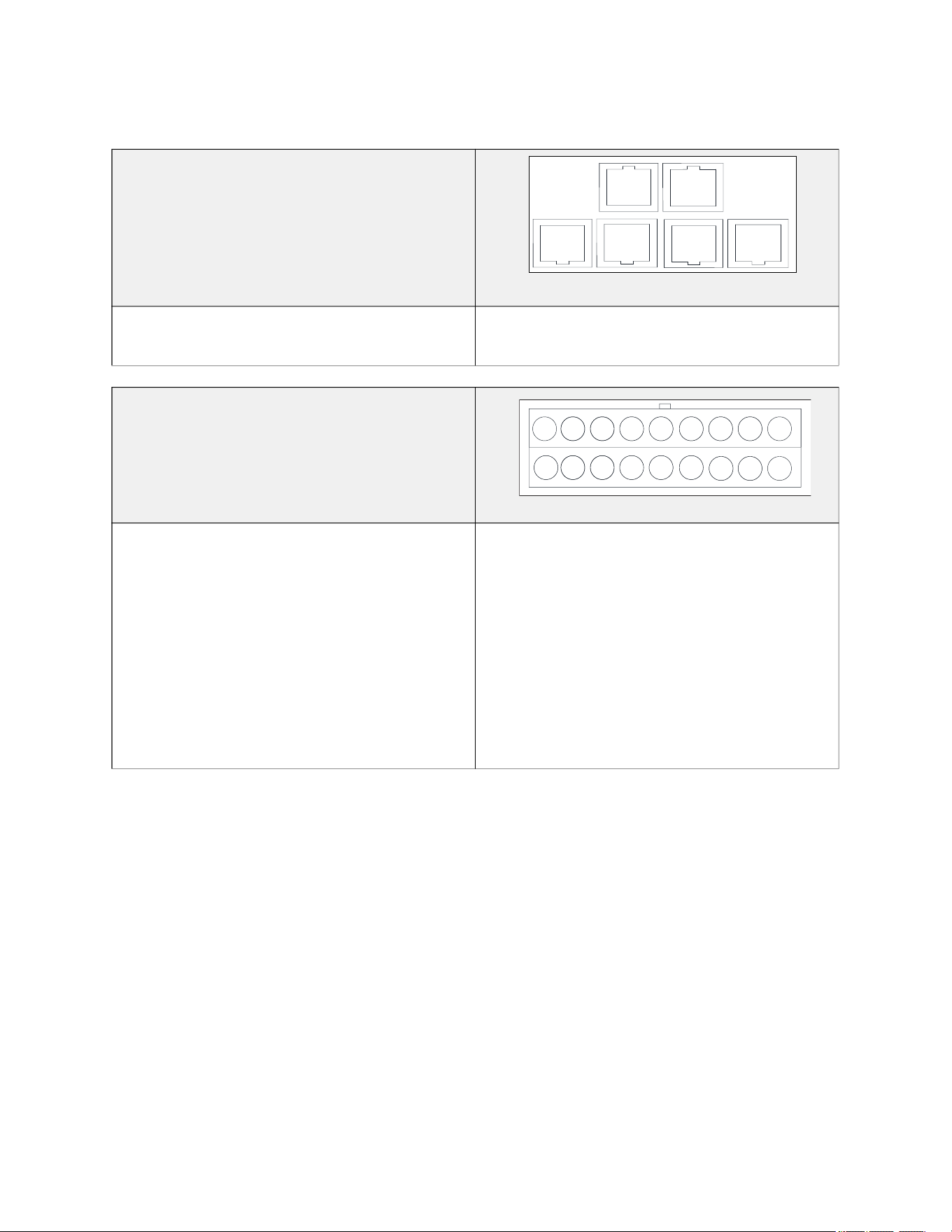
34
NOTE: Some connections may not be used dependent on system configurations
RJ45 connectors
Connector J1 and J2 are associated with BMS.
Connector J3 through J6 are interchangeable and
may be used to connect to an HMI or VFD.
J1 - CASLink/Slave
J2 - CASLink/Slave
J3 - HMI/VFD/Master
J4 - HMI/VFD/Master
J5 - HMI/VFD/Master
J6 - HMI/VFD/Master
Connector J7 contains inputs and outputs for the
Flame Safety Controller (FSC)
Pin 1 - 24VAC Output to Pressure Switch Input
(PSW) on FSC or Electric Heater (option)
Pin 2 - 24VAC Output to Thermostat Input
(TH/W) on FSC
Pin 3 - 24VAC Input from IND on FSC
Pin 4 - 24VAC Input from V1 on FSC
Pin 5 - 24VAC Output to Main Gas Valve
(Connected to J7-4)
Pin 6 - 0-10VDC + Analog Output to Modulating
Gas Valve
Pin 7 - 0-10VDC - Output to Modulating Gas Valve
Pin 8 - Modulating Gas Valve Shield
Pin 9 - 24VAC Common to Main/Pilot Gas Valve
Pin 10 - 24VAC Input from Vent Proving Switch
(J7-1) / Electric Heat Dry Contact
Pin 11 - 24VAC Output (L1) on FS
Pin 12 - 24VAC Supply Power (R) on FSC
Pin 13 - 24VAC Out to High Limit Switch
Pin 14 - 24VAC Out to Vent Proving Switch
Pin 15 - Detects 24VAC Presence from Roll Out
Switch
Pin 16 - Detects 24VAC Presence from High Limit
Switch
Pin 17 - 24VAC Out to Roll Out Switch
Pin 18 - Valve Ground (V2) on FSC/High Efficiency
(HE) Furnace Relay (RE-B)
J2
J1
J3J4J5J6
1
10
18
9
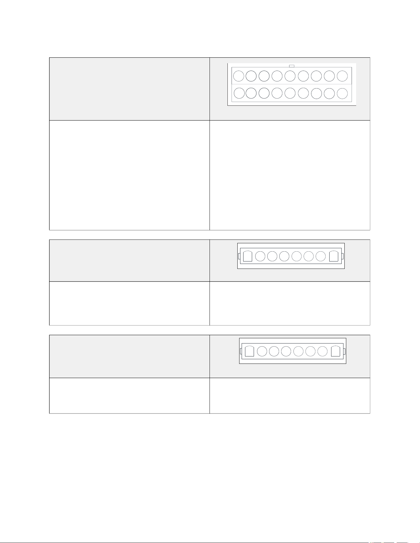
35
Connector J8 contains inputs and outputs for the
Flame Safety Controller (FSC)
Pin 1 - 24VAC Output to Pressure Switch Input
(PSW) on FSC or Electric Heater (option)
Pin 2 - 24VAC Output to Thermostat Input
(TH/W) on FSC
Pin 3 - Detects 24VAC Presence from IND on FSC
Pin 4 - 24VAC Input from V1 on FSC
Pin 5 - 24VAC Output to Main Gas Valve
(Connected to J8-4)
Pin 6 - 0-10VDC + Analog Output to Modulating
Gas Valve
Pin 7 - 0-10VDC - Output to Modulating Gas Valve
Pin 8 - Modulating Gas Valve Shield
Pin 9 - 24VAC Common to Main/Pilot Gas Valve
Pin 10 - 24VAC Input from Vent Proving Switch
(J8-1) / Electric Heat Dry Contact
Pin 11 - 24VAC Output (L1) on FSC
Pin 12 - 24VAC Supply Power (R) on FSC
Pin 13 - 24VAC Output to High Limit Switch
Pin 14 - 24VAC Output to Vent Proving Switch
Pin 15 - Detects 24VAC Presence from Roll Out
Switch
Pin 16 - Detects 24VAC Presence from High Limit
Switch
Pin 17 - 24VAC Output to Roll Out Switch
Pin 18 - Valve Ground (V2) on FSC/High Efficiency
(HE) Furnace Relay (RE-B)
Connector J9 contains 120V AC connections
Pin 1 - 120VAC Main Input
Pin 2 - N/A
Pin 3 - 120VAC Input from Fire Micro-Switch
Pin 4 - 120VAC Output to Intake/Discharge Damper
Actuator
Pin 5 - 120VAC Input from Intake Damper End
Switch
Pin 6 - 120VAC Output to Drain Heater
Pin 7 - 120VAC Output to Cabinet Heater
Pin 8 - 120VAC Neutral
Connector J10 contains 120V AC connections
Pin 1 - N/A
Pin 2 - N/A
Pin 3 - N/A
Pin 4 - 120VAC Output to Crankcase Heater
Pin 5 - N/A
Pin 6 - N/A
Pin 7 - N/A
Pin 8 - N/A
1
10
18
9
18
18
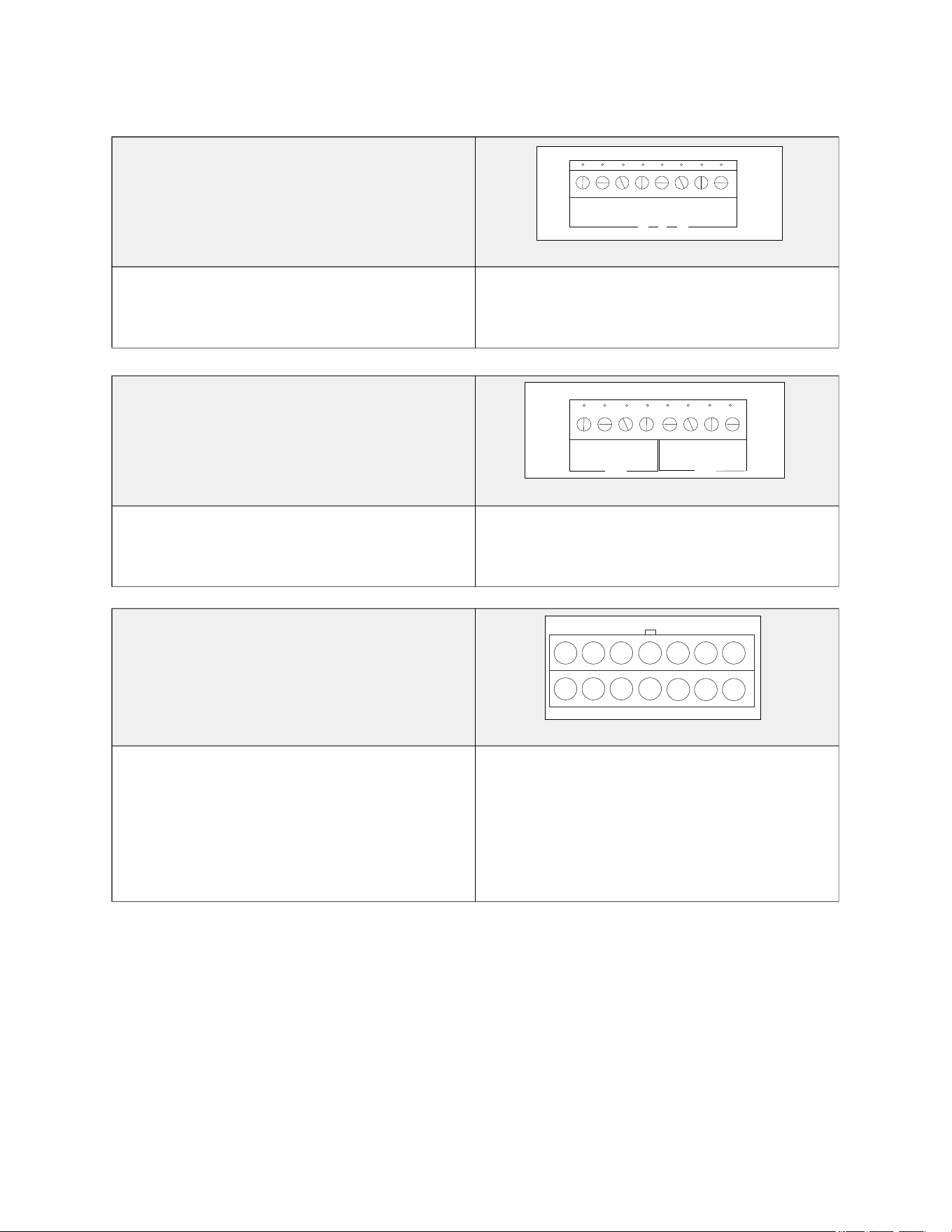
36
Connector J11 contains low voltage screw terminal
connections
Pin 1 - 24VAC Auxiliary Input
Pin 2 - 24VAC Auxiliary Input
Pin 3 - 24VAC Auxiliary Input
Pin 4 - 24VAC Call for Heat Input
Pin 5 - 24VAC Call for Cooling Input
Pin 6 - 24VAC Call for Blower Input
Pin 7 - 24VAC Occupied Override Input
Pin 8 - 24VAC Isolated Common
Connector J12 contains low voltage screw terminal
connections
Pin 1 - 24VAC Output to Smoke Detector
Pin 2 - 24VAC Output to Smoke Detector
Pin 3 - 24VAC Digital Input from Smoke Detector
Pin 4 - 24VAC Common to Smoke Detector
Pin 5 - 24VAC Output to Air Quality Sensor
Pin 6 - 0-10V Analog Input from Air Quality Sensor
Pin 7 - 24VAC Common to Air Quality Sensor
Pin 8 - 24VAC Common to Air Quality Sensor
Connector J13 contains low voltage connections
Pin 1 - N/A
Pin 2 - PWM + Output for Supply ECM
Pin 3 - 24VAC Output for Low Gas Pressure Switch
Pin 4 - 24VAC Output for High Gas Pressure Switch
Pin 5 - 24VAC Output for Clogged Filter Switch
Pin 6 - 24VAC Output for Low Airflow
Pin 7 - 24VAC Input for Board Power
Pin 8 - N/A
Pin 9 - N/A
Pin 10 - 24VAC Input from Low Gas Pressure
Switch
Pin 11 - 24VAC Input from High Gas Pressure
Switch
Pin 12 - 24VAC Input from Clogged Filter Switch
Pin 13 - 24VAC Input from Low Air Pressure Switch
Pin 14 - 24VAC for Board Power
AUX
IN1
AUX
IN2
AUX
IN3
HEAT
COOL
FAN
OCC
OVR
ISO
COM
WYG
18
BAS/STAT
24V
AC
COM
24V
AC
IN
DI-1
COM
24V
AC
VIN
AI-1
0-10
COM
18
1
7
10
14
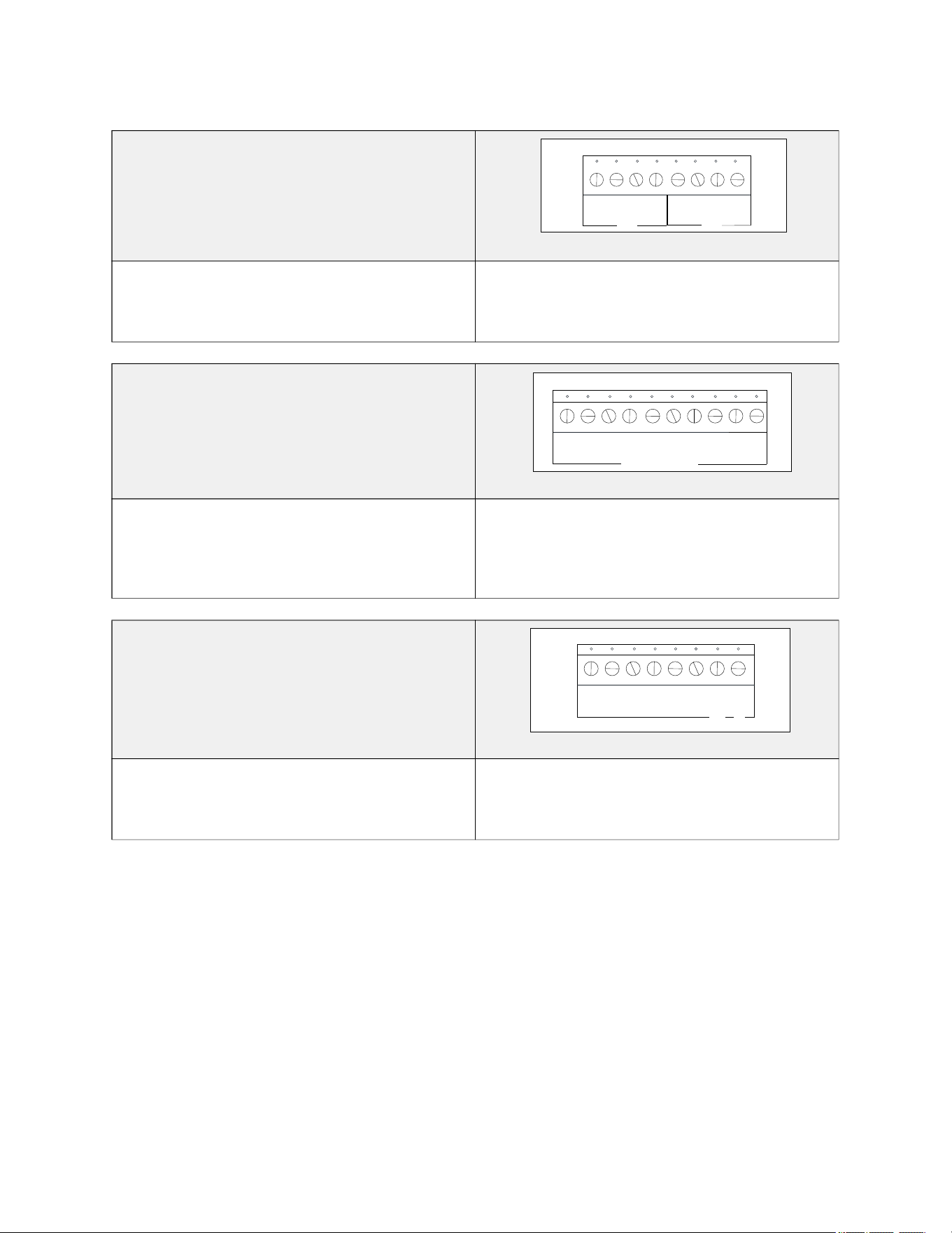
37
NOTE: Connector J17 is grouped with connectors J-19 through J-21
Connector J14 contains screw terminal
connections
Pin 1 - 24VAC Output to Intake RH
Pin 2 - 0-10VDC Analog Input from Intake RH
Pin 3 - 24VAC Common to Intake RH
Pin 4 - 24VAC Common to Humidity Sensor
Pin 5 - 24VAC Output to Space RH
Pin 6 - 0-10VDC Analog Input from Space RH
Pin 7 - 24VAC Common to Space RH
Pin 8 - 24VAC Common to Humidity Sensor
Connector J15 contains low voltage connections
Pin 1 - Intake Temperature Thermistor Input
Pin 2 - Intake Temperature Thermistor Input
Pin 3 - Return Temperature Thermistor Input
Pin 4 - Return Temperature Thermistor Input
Pin 5 - Outdoor Temperature Thermistor Input
Pin 6 - Outdoor Temperature Thermistor Input
Pin 7 - Discharge Temperature Thermistor Input
Pin 8 - Discharge Temperature Thermistor Input
Pin 9 - Space Temperature Thermistor Input
Pin 10 - Space Temperature Thermistor Input
Connector J16 contains low voltage screw terminal
connections
Pin 1 - 0-10VDC Analog Input
Pin 2 - 4-20 mA Analog Input
Pin 3 - 24VAC Common
Pin 4 - 24VAC Common
Pin 5 - 24VAC Unit Interlock Input
Pin 6 - 24VAC Output Stat tied to J12-7
Pin 7 - 24VAC Output (R) tied to J12-6
Pin 8 - 24VAC Common
24V
DC
COM
AI-2
COM
24V
DC
VIN
0-10
COM
18
VIN
0-10
COM
AI-3
IT
110
THERMISTORS
IT
RT
RT
OT
OT
DT
DT
ST
ST
0-10
VOLT
4-20
mA
UNIT
INTLK
COM
18
BAS/STAT
COM
COM
24V
AC
24V
AC
RC
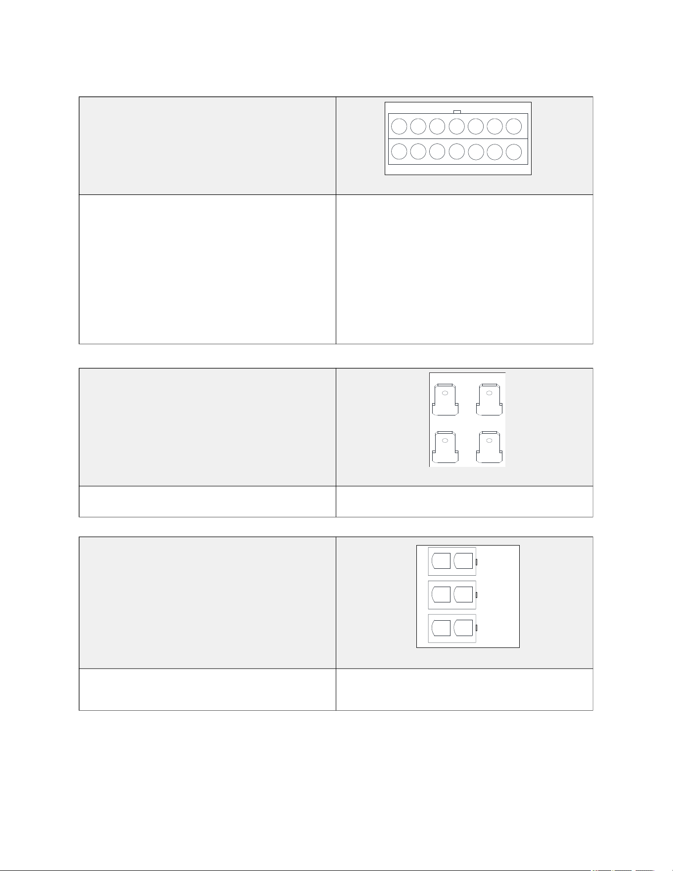
38
Connector J18 contains low voltage connections
Pin 1 - 24VDC + Output for Spare
Pin 2 - 0-10VDC Analog Output for Mixing Box
Actuator
Pin 3 - 0-10VDC Analog Output for Bypass Damper/
Powered Exhaust
Pin 4 - 24VAC Output for DX Float Switch
Pin 5 - 24VAC Output for Door Interlock
Pin 6 - 24VAC Extreme Low Ambient Bypass
Solenoid Output
Pin 7 - 24VAC for Damper Actuator
Pin 8 - 24VDC - Common for Spare
Pin 9 - 0-10VDC Analog Output for Mixing Box
Actuator
Pin 10 - 0-10VDC Analog Output for Bypass
Damper/Powered Exhaust
Pin 11 - 24VAC Input from DX Float Switch
Pin 12 - 24VAC Input from Door Interlock
Pin 13 - 24VAC Extreme Low Ambient Bypass
Solenoid Common
Pin 14 - 24VAC for Damper Actuator
Connector J17 Output for Power Vent 1
Connector J19 Output for Power Vent 2
Connector J20 Neutral for Power Vent
Connector J21 Neutral for Power Vent
J17 - 120VAC Output for Power Vent 1
J19 - 120VAC Output for Power Vent 2
J20 - 120VAC Neutral for Power Vents
J21 - 120VAC Neutral for Power Vents
Connector J22 (Y1) N/A
Connector J23 (Y2) Reversing Valve
Connector J24 (Y3) N/A
J22 Pin 1 - N/A
J22 Pin 2 - N/A
J23 Pin 1 - 24VAC Output to Reversing Valve 1
J23 Pin 2 - 24VAC Common to Reversing Valve 1
J24 Pin 1 - N/A
J24 Pin 2 - N/A
1
7
10
14
J20 J21
J19
J17
J22
1
2
1
2
1
2
J23
J24
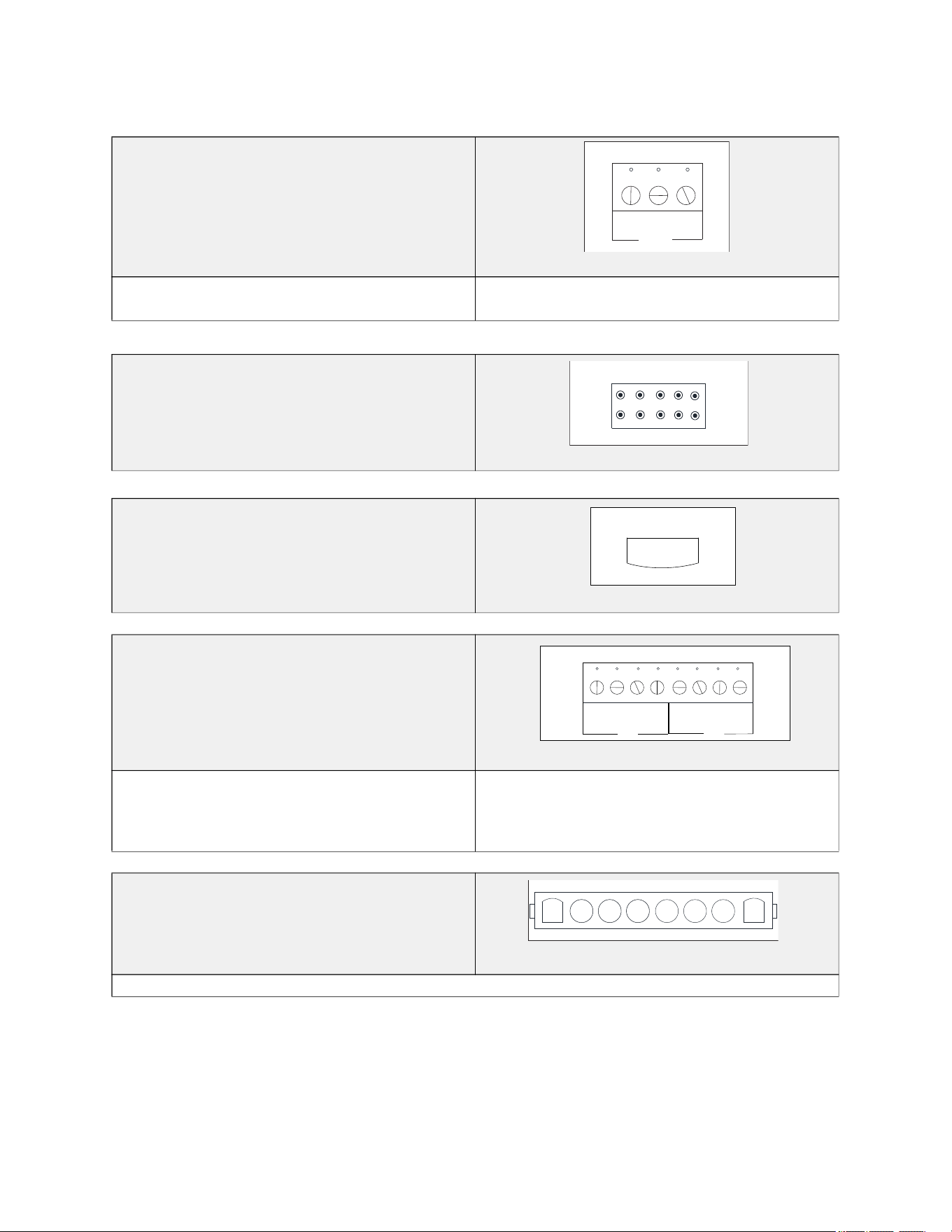
39
Connector J25 contains low voltage screw terminal
connections for DDC Communications Isolated
Pin 1 - RS-485 +
Pin 2 - RS-485 -
Pin 3 - RS-485 Common
Connector J26 Programming Port
Connector J27 USB Programming Port
Connector J28 contains low voltage screw terminal
connections
Pin 1 - 24VAC Output
Pin 2 - 24VAC Output
Pin 3 - 24VAC Digital Input
Pin 4 - 24VAC Common
Pin 5 - 24VAC Output to Supply Fan
Pin 6 - 0-10VDC Analog Input Supply Fan Speed
Pin 7 - 24VAC Common to Supply Fan
Pin 8 - 24VAC Common to Supply Fan
Connector J29 contains 120V AC connections
N/A
1
3
DDC
C-+
1
2
USB
24V
AC
COM
24V
AC
IN
DI-2
COM
24V
AC
VIN
AI-4
0-10
COM
18
18
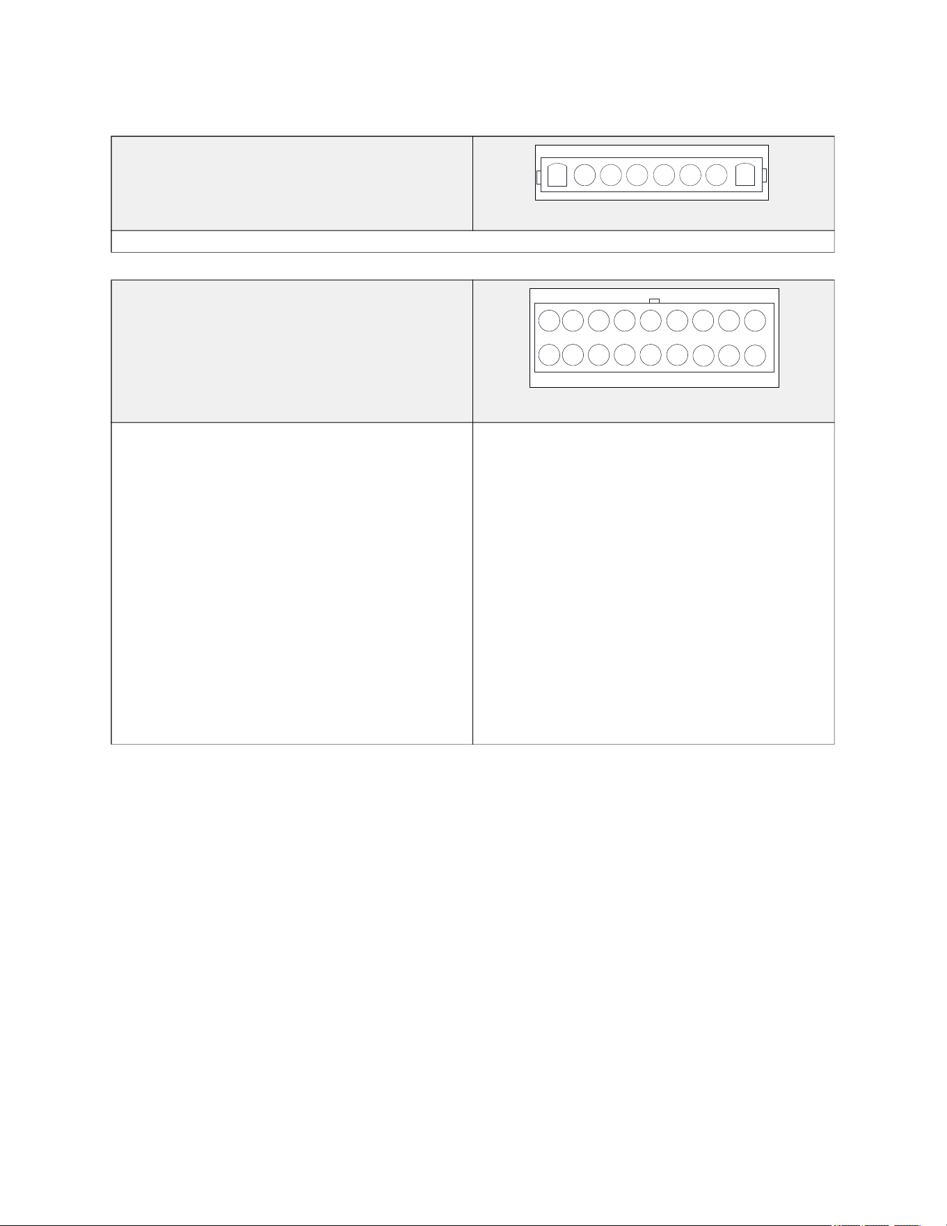
40
Connector J30 contains 120V AC connections
N/A
Connector J31 contains inputs and outputs for
components
Pin 1 - 24VDC + Output to Outdoor RH Sensor
Pin 2 - 0-10VDC Analog Input from Outdoor RH
Sensor
Pin 3 - 24VDC/0-10VDC Common from Outdoor RH
Sensor
Pin 4 - 24VDC + Output to Inlet Gas Pressure
Sensor
Pin 5 - 0-10VDC Analog Input from Inlet Gas
Pressure Sensor
Pin 6 - 24VDC/0-10VDC Common from Inlet Gas
Pressure Sensor
Pin 7 - 24VDC + Output to Discharge RH Sensor
Pin 8 - 0-10VDC Analog Input from Discharge RH
Sensor
Pin 9 - 24VDC/0-10VDC Common from Discharge
RH Sensor
Pin 10 - 24VDC + output to Return RH Sensor
Pin 11 - 0-10VDC Analog Input from Return RH
Sensor
Pin 12 - 24VDC/0-10VDC Common from Return RH
Sensor
Pin 13 - 24VDC + output to Clogged Filter Pressure
Sensor
Pin 14 - 0-10VDC Analog Input from Clogged Filter
Pressure Sensor
Pin 15 - 24VDC/0-10VDC Common from Clogged
Filter Pressure Sensor
Pin 16 - 24VDC + Output for Analog or Static
Pressure Control for Blower/Damper
Pin 17 - 0-10VDC Analog Input for Analog or Static
Pressure Control for Blower/Damper
Pin 18 - 24VDC/0-10VDC Common for Analog or
Static Pressure Control for Blower/Damper
18
1
9
10
18
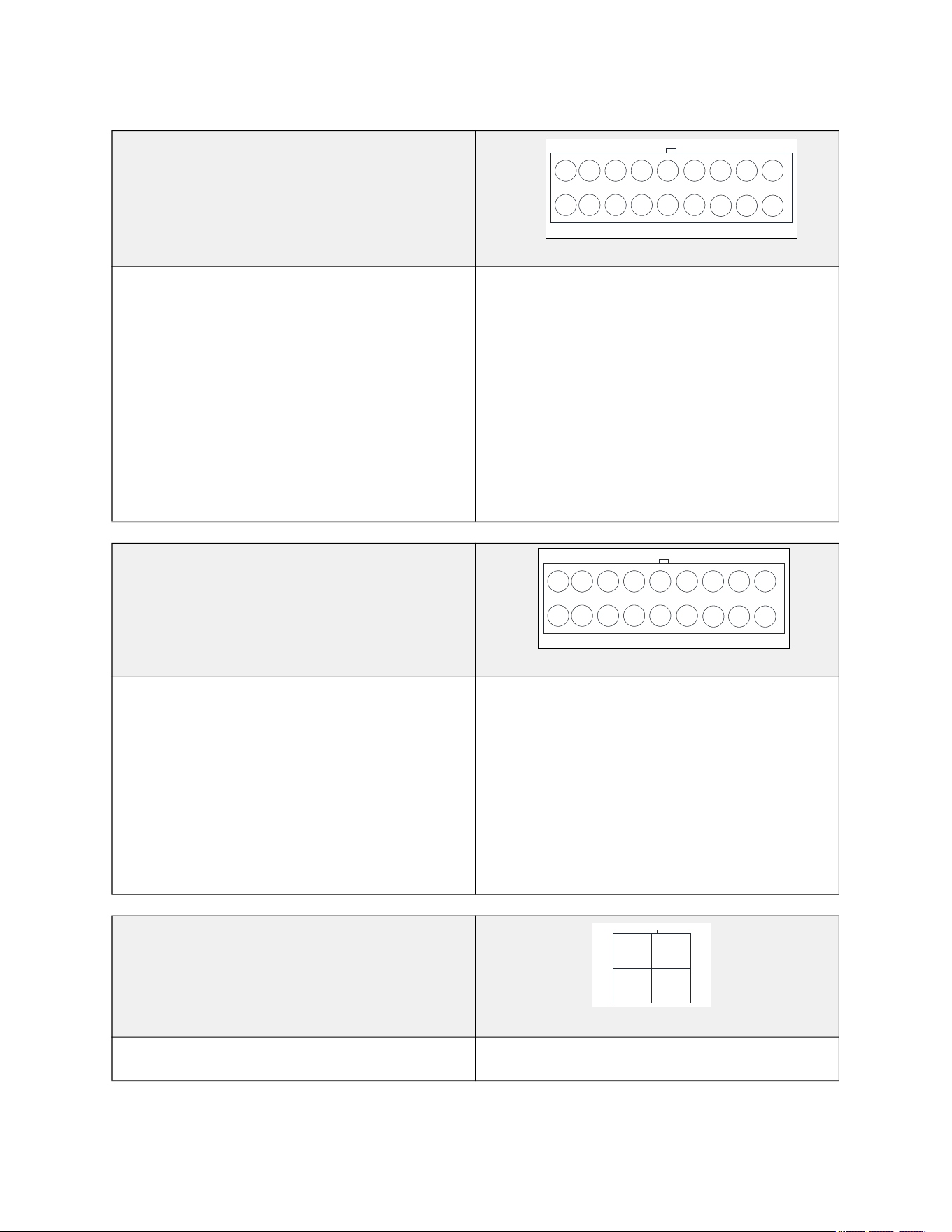
41
Connector J32 contains inputs and outputs for
components
Pin 1 - 24VAC Output for High Air Airflow Switch
Pin 2 - PWM + Output for Exhaust/Power Vent ECM
Pin 3 - 24VAC Output for Proof Of Closure / HE
Furnace Float Switch
Pin 4 - 24VDC + Output for Exhaust Current Sensor
Pin 5 - 24VAC Output To CO Alarm
Pin 6 - 0-24VDC + Analog Input from Flame Sensor
Pin 7 - 24VDC Powered PWM to Modulating Gas
Valve, Full Wave, 16 kHz
Pin 8 - 0-10VDC Analog Output
Pin 9 - 0-10VDC Analog Output for Electric Heat
Pin 10 - 24VAC Input from High Airflow Switch
Pin 11 - PWM - Output for Exhaust/Power Vent
ECM
Pin 12 - 24VAC Input from Proof of Closure / HE
Furnace Float Switch
Pin 13 - 4-20mA Input from Exhaust Current Sensor
Pin 14 - 24VAC From CO Alarm
Pin 15 - 24VDC Common From Flame Sensor
Pin 16 - 24VDC Powered PWM to Modulating Gas
Valve, Full Wave, 16 kHz
Pin 17 - 0-10VDC Analog Output
Pin 18 - 0-10VDC Analog Output for Electric heat
Connector J33 contains inputs and outputs for
components
Pin 1 - 24VDC + Output for Main Unit Current
Sensor
Pin 2 - 24VDC + Output for Cooling Current Sensor
Pin 3 - PWM + Output for Condenser Fans 1
Pin 4 - PWM + Output for Condenser Fans 2
Pin 5 - PWM + Input for Spare 1
Pin 6 - 24VDC + Pulse Input from Gas Meter
Pin 7 - 24VDC + Pulse Input from Water Meter
Pin 8 - 24VAC Output to Oil Solenoid
Pin 9 - 0-10VDC Analog Input for CFM Monitor
Pin 10 - 4-20mA Input from Main Unit Current
Sensor
Pin 11 - 4-20mA Input from Cooling Current Sensor
Pin 12 - PWM - Output for Condenser Fans 1
Pin 13 - PWM - Output for Condenser Fans 2
Pin 14 - PWM - Input for Spare 1
Pin 15 - PWM - Pulse Input from Gas Meter
Pin 16 - 24VDC - Pulse Input from Water Meter
Pin 17 - 24VAC Common for Oil Solenoid
Pin 18 - 0-10VDC Common for CFM Monitor
Connector J34 Stepper Motor (EEV)
Pin 1 - Stepper Motor 1, 12V, Bipolar
Pin 2 - Stepper Motor 1, 12V, Bipolar
Pin 3 - Stepper Motor 1, 12V, Bipolar
Pin 4 - Stepper Motor 1, 12V, Bipolar
1
9
10
18
1
9
10
18
34
21
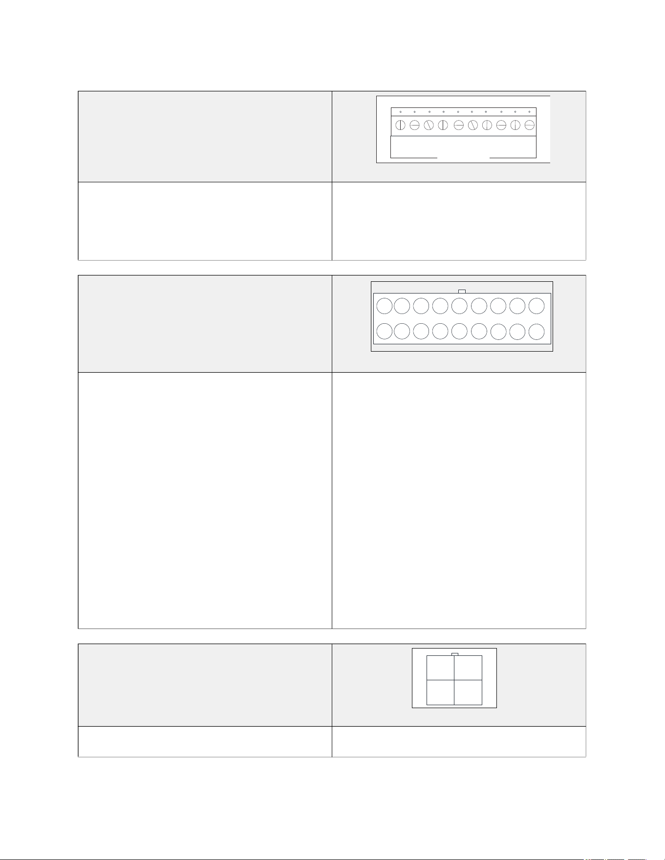
42
Connector J35 contains low voltage connections
Pin 1 - Suction Line Thermistor Input
Pin 2 - Suction Line Thermistor Input
Pin 3 - Liquid Line Thermistor Input
Pin 4 - Liquid Line Thermistor Input
Pin 5 - Evap/Indoor Thermistor Input
Pin 6 - Evap/Indoor Thermistor Input
Pin 7 - Condenser/Outdoor Coil Thermistor Input
Pin 8 - Condenser/Outdoor Coil Thermistor Input
Pin 9 - Compressor Discharge Thermistor Input
Pin 10 - Compressor Discharge Thermistor Input
Connector J36 contains inputs and outputs for
components
Pin 1 - 24VAC Output for Low Pressure Switch
Pin 2 - 24VAC Input for Low Pressure Switch
Pin 3 - 24VAC Output for High Pressure Switch
Pin 4 - 24VAC Input for Low Pressure Switch
Pin 5 - 24VAC Output for High Temp Switch
Pin 6 - 24VAC Input for Low Pressure Switch
Pin 7 - 24VAC Output to Oil Sensor
Pin 8 - 24VAC Common from Oil Sensor
Pin 9 - 24VAC Input from Oil Sensor
Pin 10 - 24VDC + output to Liquid Line Pressure
Transducer
Pin 11 - 0-10VDC Analog Input from Liquid Line
Pressure Transducer
Pin 12 - 24VDC/0-10VDC Common from Liquid Line
Pressure Transducer
Pin 13 - PWM - 24VDC + Output to Suction Line
Pressure Transducer
Pin 14 - PWM - 0-10VDC Analog Input from Suction
Line Pressure Transducer
Pin 15 - PWM - 24VDC/0-10VDC Common from
Suction Line Pressure Transducer
Pin 16 - 24VDC - 24VDC + output to Discharge Line
Pressure Transducer
Pin 17 - 0-10VDC Analog Input from Discharge Line
Pressure Transducer
Pin 18 - 24VDC/0-10VDC Common from Discharge
Line Pressure Transducer
Connector J37 Stepper Motor (Reheat Valve)
Pin 1 - Stepper Motor 2, 12V, Bipolar
Pin 2 - Stepper Motor 2, 12V, Bipolar
Pin 3 - Stepper Motor 2, 12V, Bipolar
Pin 4 - Stepper Motor 2, 12V, Bipolar
SLT
110
THERMISTORS
SLT
LLT
LLT
ICT
ICT
OCT
OCT
CDT
CDT
1
9
10
18
34
21
43
Connector J38 Modbus
Pin 1 (A) - Modbus (-)
Pin 2 (B) - Modbus (+)
Pin 3 (C) - Modbus Ground
Dip Switch S1
Switch 1, 2, 3 always OFF. Switch 4 Always ON. If Switch 4 is OFF, BAS terminals disabled.
Dip Switch S2
Programming - Service Only
Dip Switch S3
End of line termination
Dip Switch S4
Programming - Service Only
13
MODBUS
CBA
ON
123
4
ON
12
ON
ON
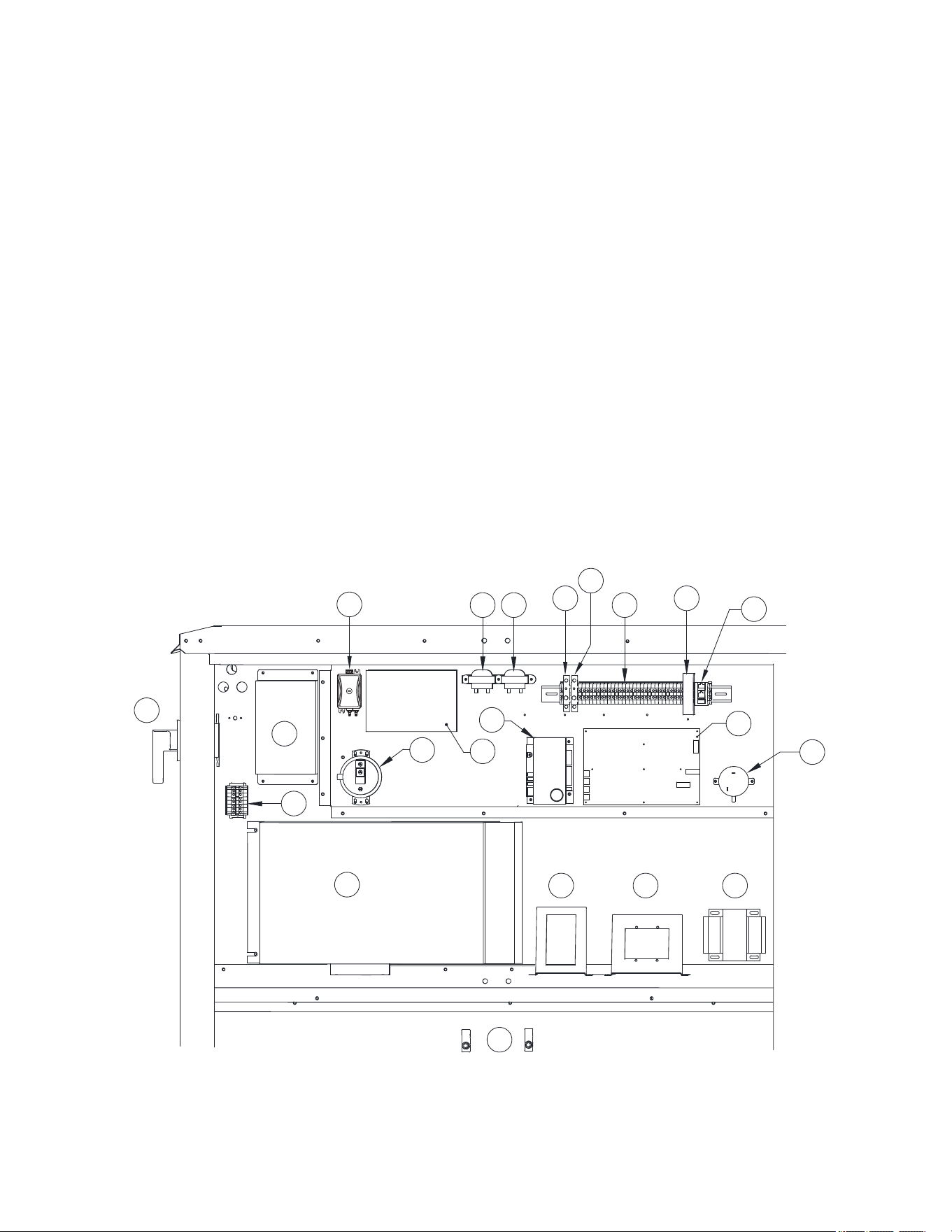
44
Optional Components
AC Interlock
On units equipped with the optional AC interlock, 24V AC power from a rooftop unit should be field wired to
screw terminal J11-(5) on the MUA board. 24V AC common from a rooftop unit should be field wired to
terminal block J11-(8) on the MUA board. When these terminals are powered, heat will be locked out on
the RTU.
Burner Interlock
On units equipped with the optional burner interlock, 24V AC power from a rooftop unit should be field
wired to screw terminal J11-(4) on the MUA board. 24V AC common from a rooftop unit should be field
wired to terminal block J11-(8) on the MUA board. When these terminals are powered, cooling will be
locked out on the RTU.
Electric Cabinet Heater
Units can be shipped with an optional 120V electric cabinet heater powered from the MUA board. There is
a temperature sensor built onto the MUA board that will regulate when the cabinet heater activates.
Component Location
Use Figure 22 through Figure 28 for component locations. Units equipped with ERV, refer to “Energy
Recovery (Optional)” on page 94 for component descriptions and locations.
Figure 22 - Typical Main Cabinet
15
21
6
8
12
9
16
18
13
17
3
19
10
14
4
7
11
20
2
1
5

45
1. Differential Pressure Transducer – Monitors the air pressure differential between two points. This
transducer is used in different air control options.
2. 40VA 120V to 24V Transformer (TR-xx) – Verify transformers on schematics. Will vary by application.
3. 20VA 120V to 24V Transformer (TR-xx) – Verify transformers on schematics. Will vary by application.
4. Convenience Outlet Circuit Breaker (CB-02) – Protects transformer for convenience outlet from high
current spikes.
5. Circuit Breaker (CB-01) – Protects electrical components from high current spikes.
6. Terminal Strip – Central location to terminate control wiring. Should be used for troubleshooting.
7. 24V DC Power Supply (PWS-01) – Converts input voltage of 100-240V AC to an output voltage of
24V DC.
8. RJ45 Converter – Communication port for a Cat 5 cable that allows components to connect to other
components.
9. Induced Draft Air Sensor (PS-01) – A safety device located near the draft inducer motor that will
prevent operation of the furnace if correct venting air pressures are not detected.
10. MUA Board - Controls the 0-10V DC signal to modulating furnace controls, modulating gas valve, and
24V AC signals to staged furnace controls.
11. Flame Safety Control (FSC-01) – Initiates and monitors flame. Equipped with non-adjustable time
settings for pre-purge, inter-purge, and post-purge of the exhaust flue and control cabinet.
12. 750V 230/460V to 120V Transformer – Used for the convenience outlet. Voltage inputs 208/230/480.
13. Clogged Filter Switch (PS-10) – Senses whether the filters at the intake to the main supply motor are
free of dirt and contaminant. This is an optional component.
14. VFD Controller (VFD-01) – Used to protect supply motor, and to control the speed of the motor to vary
airflow across unit.
15. Distribution Block – Distributes power to condensing components.
16. Disconnect Switch (SW-01) – Controls all electrical power to the entire unit.
17. Compressor Drive Frequency Converter (VFD-02) – Operates the compressor.
18. Compressor Local Control Panel (LCP) – Used to navigate the compressor’s VFD controls.
19. HMI Panel – MUA board interface. The 4 buttons are used to navigate through the menu screens.
20. Convenience Outlet Transformer (TR-09) – 2000VA transformer used for the convenience outlet.
Voltage inputs 208/230/480.
21. Door Switches (DS-xx) – These switches operate the LED lights inside the cabinet.
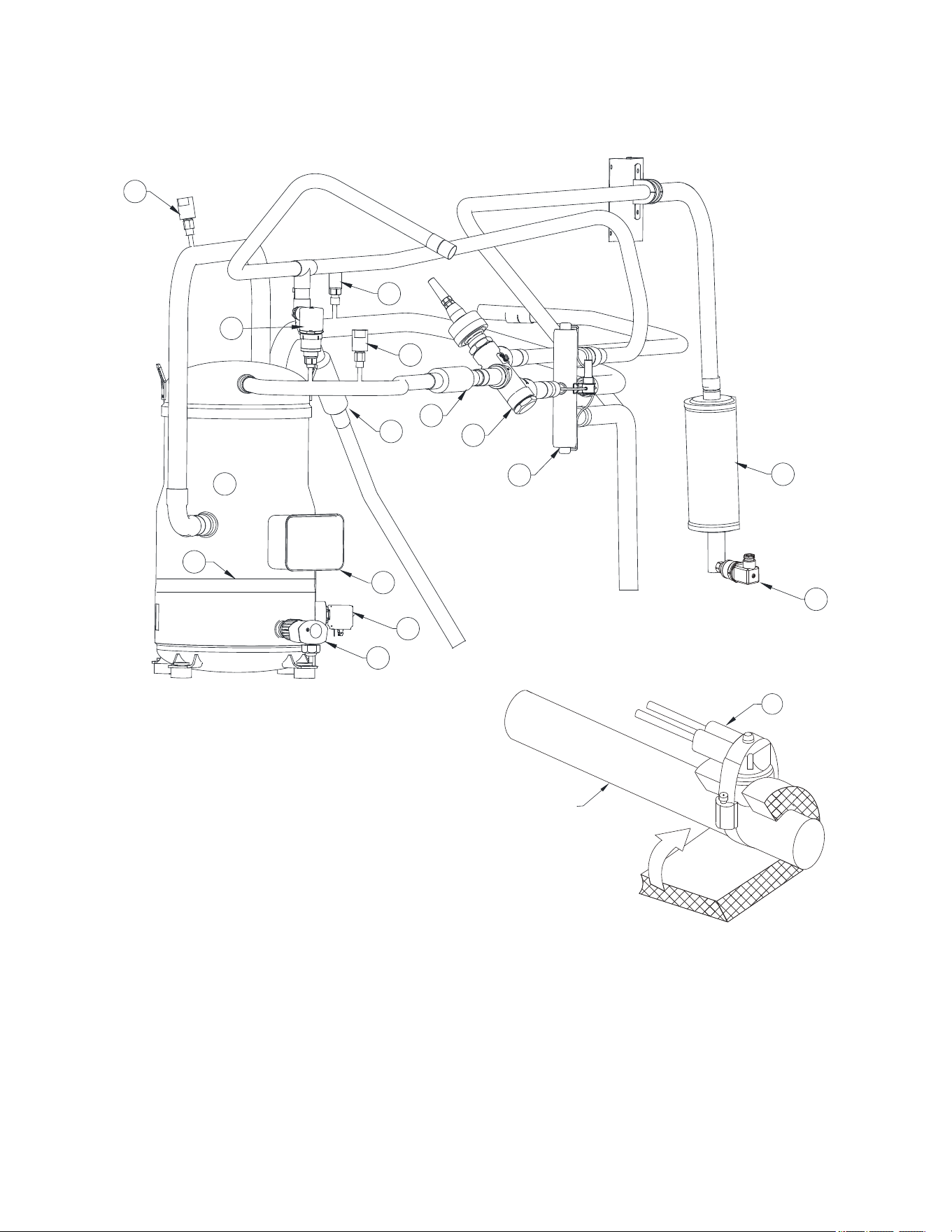
46
Figure 23 - Typical Refrigerant Access Panel Heat Pump with Reheat shown
14
4
10
2
5
8
11
6
7
12
9
3
1
13
15
Discharge
Line
16

47
1. Refrigerant Low Pressure Switch (SW-15) – Detects refrigerant pressure on the low-pressure side
of the system. If the pressure drops below the preset value, the compressor will shut down. This
sensor has an automatic reset.
2. Suction (Low) Line Pressure Sensor (PS-21) – Pressure transducer that monitors the low side of the
refrigeration system.
3. Filter/Drier – Absorbs water and filters system contaminants.
4. Reversing Valve (RV-01) – A valve used for heat pump applications that changes the flow of
refrigerant. By changing the flow of refrigerant, the heat pump cycle is changed from cooling to heating
or heating to cooling.
5. Hot Gas Reheat Valve(s) – Valve(s) will modulate the supply of refrigerant to the outdoor
(condensing) coil and to the reheat coil. Units with a single reheat valve, HG-01, will be a three-way
valve. Units that use dual reheat valves, not shown, will have HG-01 in-line to the reheat coil inlet and
HG-02 in-line to the outdoor (condensing) coil inlet.
6. Discharge Check Valve – Restricts liquid migration back to compressor during off cycles.
7. Refrigerant High Pressure Switch (SW-16) – If the pressure rises above the preset value, the
compressor will shut down.
8. Discharge (High) Pressure Transducer (PS-22) – Pressure transducer that monitors the high side of
the refrigeration system.
9. Reheat Coil Check Valve – Restricts refrigerant flow to the reheat coil when reheat is not active.
10. Compressor Power Termination – Power connection from Compressor Drive Frequency Converter.
11. Oil Return Solenoid Valve (OS-01) – Allows oil to be distributed throughout the scroll set when
activated. Not applicable to VZH-044/065 compressors.
12. Oil Level Sensor (SEN-01) – Monitors the oil level in the compressor. If the oil level is low, the unit will
shut down.
13. Crankcase Heater (HE-03) – A heating cable used to boil off liquid refrigerant within the crank of the
compressor.
14. Compressor – Circulates refrigerant throughout the system.
15. Liquid Line Pressure Sensor (PS-20) – Pressure transducer that monitors the liquid line pressure in
the refrigeration system.
16. Refrigerant High Temperature Switch (SW-18) – This safety switch opens at dangerously high
compressor discharge temperatures. For heat pump applications only.
Not Shown:
• High-Pressure Port – High-pressure gauge connection port.
• Low-Pressure Port – Low-pressure gauge connection port.
• Accumulator – The accumulator prevents liquid flood back to the compressor. Used in heat pump and
certain cooling applications.
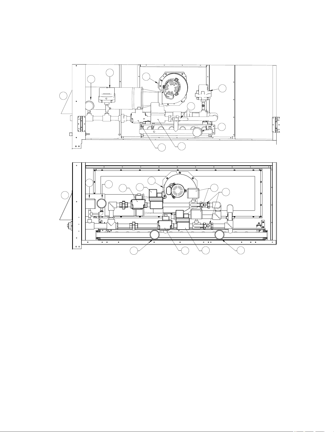
48
Figure 24 - Gas Furnace Cabinet
1. Furnace Power Vent (PV-xx) – An assembly used to exhaust flue gases.
2. High-Pressure Gas Switch (PS-03) – Monitors pressure and shuts down heating when pressures
rise above the desired set point. This is an optional component.
3. Manifold Gas Pressure Gauge (0-10” wc) – Measures manifold gas pressure.
4. Manual Gas Shut Off Valve – Allows gas flow to burner. Shut off to leak test gas train.
5. Modulating Gas Valve (VA-03) – Controls the amount of gas to the furnace to meet desired
discharge/space temperature.
6. ON/OFF Gas Valve (VA-01) – On/Off gas valve with built-in regulator and manual shut off switch.
7. Low-Pressure Gas Switch (PS-04) – Monitors pressure and shuts down heating when pressure
drops below the desired set point. This is an optional component.
8. Inlet Gas Pressure Gauge (0-35” wc) – Measure inlet gas pressure.
9. For standard furnaces, a stainless steel type B vent will be used. For High Efficiency (HE) furnace, a
PVC vent will be used. See “Furnace Condensation Drain” on page 17.
1
2
3
4
7
8
9
Typical Standard Gas Furnace
High Turndown Furnace Option
9
8
7
5
3
3
5
2
4
1
5
6
6
6
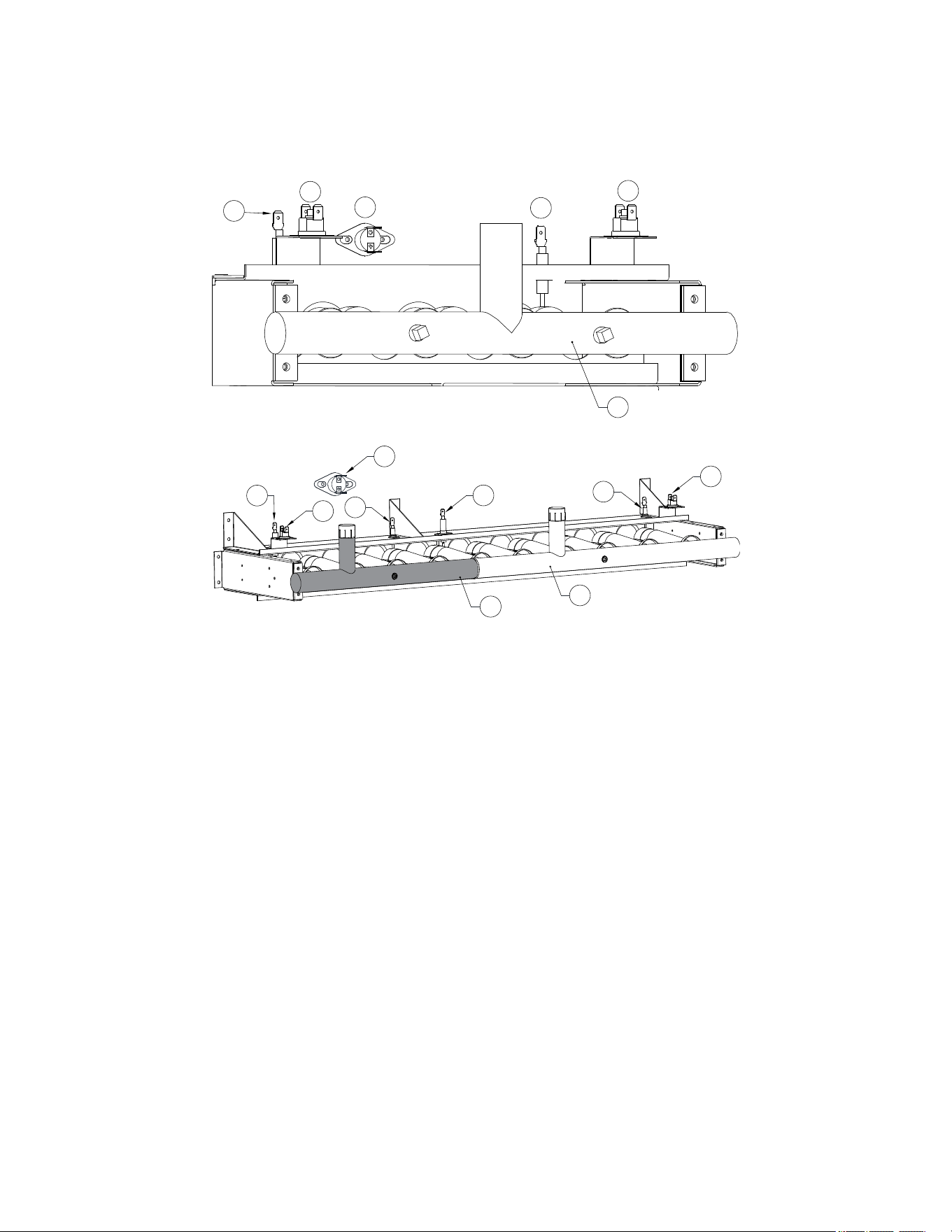
49
Figure 25 - Typical Burner Cabinet
1. Ignitor – Powered by Flame Safety Control to initiate light-off.
2. Rollout Switch 1 (SW-05) – Normally closed temperature activated switch. Mounted on bracket at the
firing tube. Senses flame roll-out in the event of a blocked tube, low airflow, or low gas pressure. If
flame-rollout is present, the switch de-energizes heater circuit on the furnace. Must be manually reset
by pressing the small button on top of the switch.
3. Furnace High Temperature Switch (SW-04) – Normally closed switch. De-energizes the heater
circuit on the furnace if temperature exceeds mechanical set-point. Automatic recycling.
4. Flame Rod (FR-01) – Continuously senses for the presence of flame in heating mode after ignition
has commenced. This sensor is wired to the Flame Safety Control (FSC-1).
5. Rollout Switch 2 (SW-13) – Normally closed temperature activated switch. Mounted on bracket at the
firing tube. Senses flame roll-out in the event of a blocked tube, low airflow, or low gas pressure. If
flame-rollout is present, the switch de-energizes heater circuit on the furnace. Must be manually reset
by pressing the small button on top of the switch.
6. Single Burner Assembly – Capacity varies by unit size.
7. Split Furnace Assembly – Capacity varies by unit size. When the high turndown option is selected, a
split furnace will be present.
A. First Stage – Smallest of the two stages. The first stage can modulate for the highest turndown.
B. Second Stage – When first stage is 100% operational, the second stage can modulate to meet the
required heating capacity.
1
2
5
3
4
Split Burner
4
5
1
3
2
1
Single Burner
4
7B
6
7A
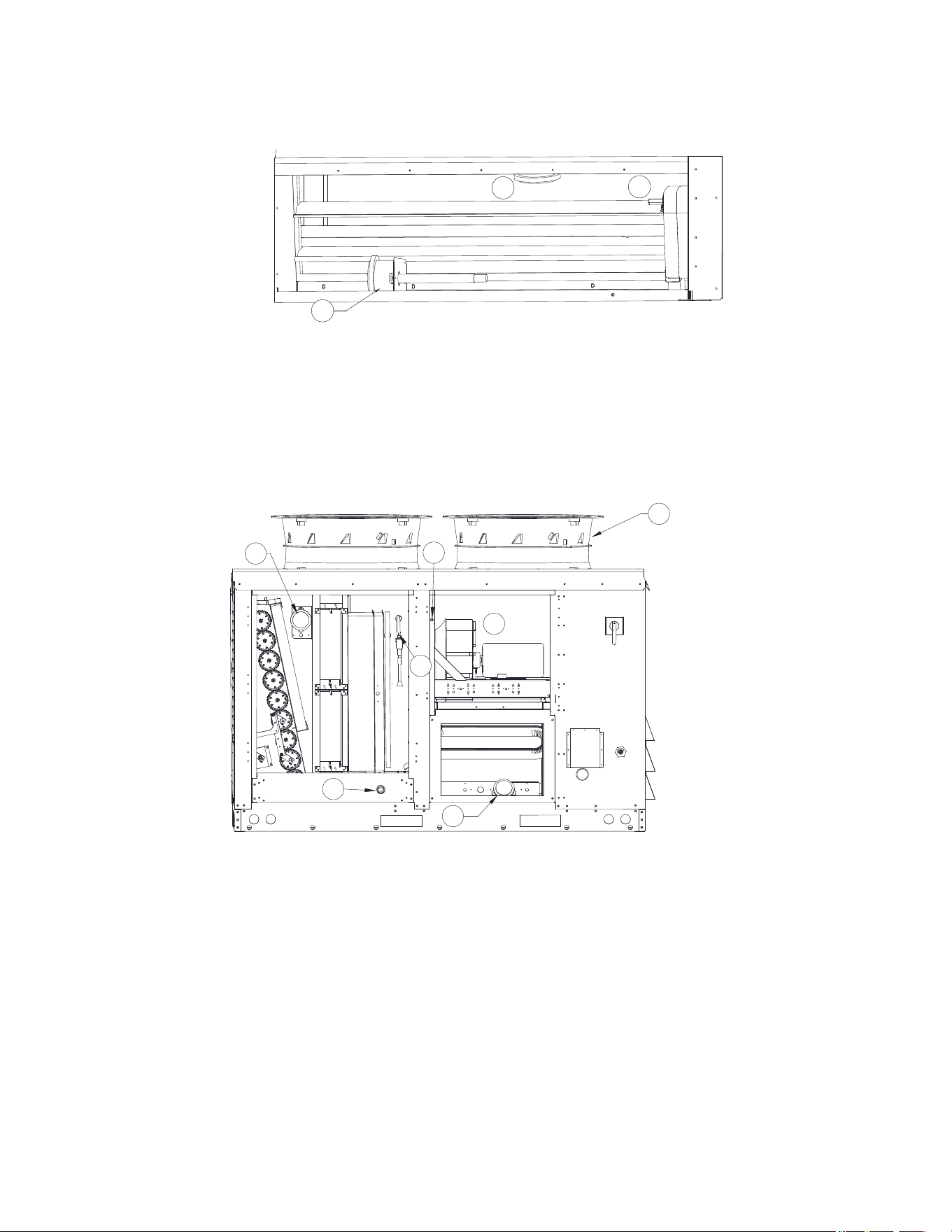
50
Figure 26 - Typical Damper Access Panel
1. Return Temperature and/or Humidity Sensor (SN-xx) – Monitors the return air temperature and/or
humidity.
2. Outdoor Temperature Sensor (SN-xx) – Monitors the outdoor temperature. Located behind outside
air intake louvers.
3. Intake Damper Assembly Motor (MT-xx) – Provides control of the outside/return air damper
assembly.
Figure 27 - Typical Blower and Air Intake Access Doors/Panel
1. Condensing Fan Motor (MT-xx) – Pulls air across the outdoor coil.
2. Supply Motor (MT-01) – Located behind door. Main supply air motor.
3. Discharge Temperature Sensor or Discharge Humidity/Temperature (SN-xx) – Monitors
discharge air temperature or humidity/temperature.
4. Door Tamper Switch (SW-19) – When the blower door is open, the switch will de-activate the supply
motor.
5. Electronic Expansion Valve (EEV-1) – Controls the flow of refrigerant to maintain a desired
superheat value.
6. Intake Temperature or Intake Humidity/Temperature Sensor (SN-xx/HUM-xx) – Monitors intake air
humidity/temperature.
7. Float Switch (SW-xx) – Monitors the water level from condensation in the drain pan.
Not Shown: Evap Coil Temperature Sensor (SN-xx) – Monitors the dew point temperature of the air
before the reheat coil.
1
2
3
1
6
7
3
4
5
2
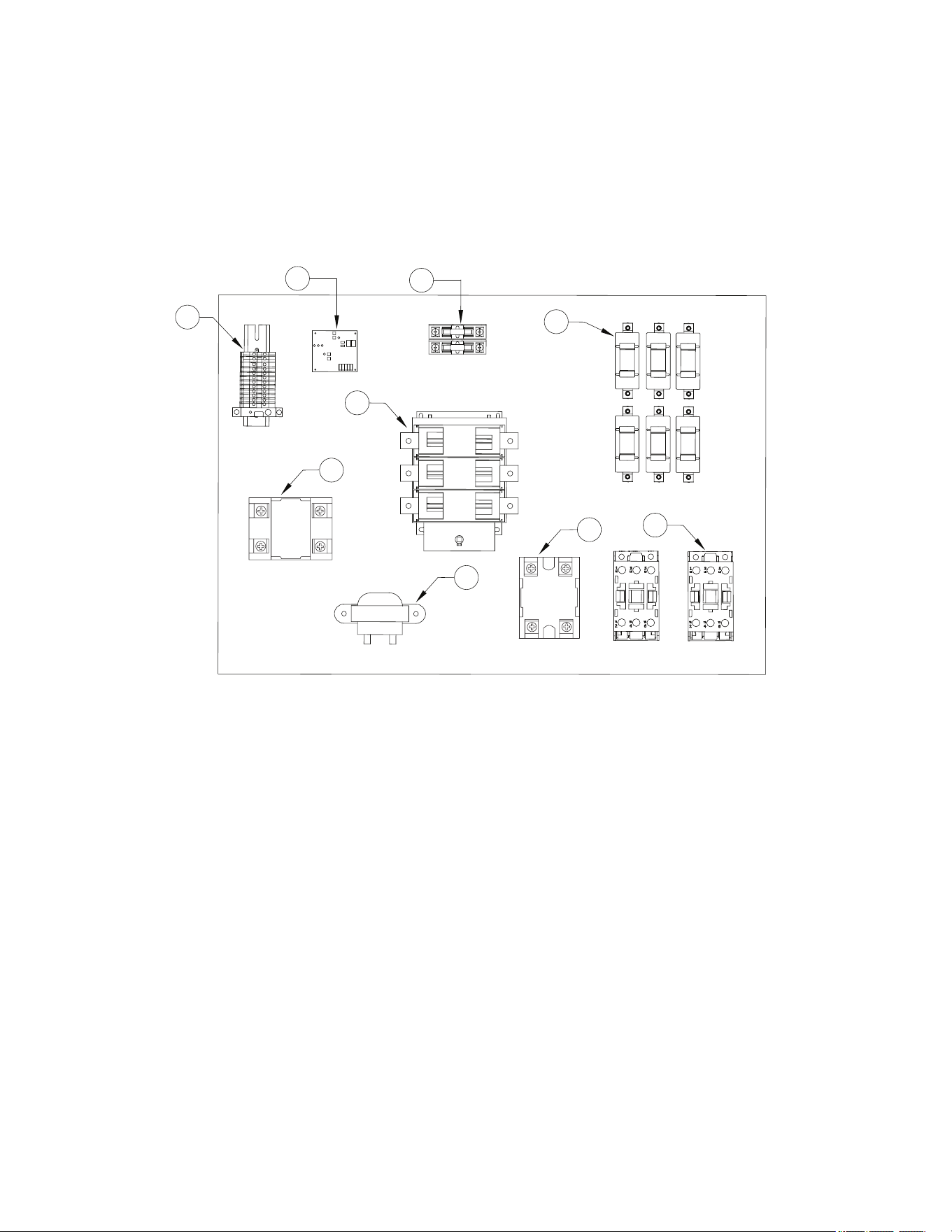
51
Electric Heater Option
The electric coils on the heater are controlled using Silicon Controller Rectifier (SCR) controls. SCR is a
time proportioning type controller that modulates the heater and supplies the exact amount of power to
match the heat demand.
The three black wires from the electric heater will need to be field wired to the disconnect switch.
Figure 28 - Electric Heater Option
1. Terminal Strip – Central location to terminate control wiring. Should be used for troubleshooting.
2. Stage Controller – Controls multiple heating stages in a pre-determined sequence. Works in
conjunction with a proportional thermostat (not shown). A sensor is mounted in the blower housing for
discharge control. The set-point is mounted remotely for either space control or discharge control.
3. Stage Fuses - Protect the total load and/or individual heater stages.
4. Mercury Contactor – Provides power to the individual stages of the heater (optional for quieter
operation).
5. Coil Contactor - Energizes coil when there is a signal from step controller.
6. Magnetic Contactor - Provides power to the individual stages of the heater.
7. Transformer - Supplies power to the control circuit. Supplied with a fuse.
8. Solid State Relay (SSR) - Proportionally controls the amount of power transmitted to the heating
elements.
9. Disconnect Switch – Interrupts power to the electric coil.
1
2
3
4
5
6
7
8
9
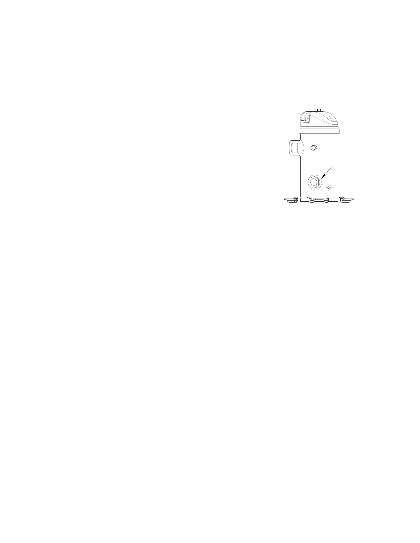
52
Compressor Information
Oil return management – Insufficient lubrication can be the result of oil depositing itself in pipes and
bends. Return management helps oil deposits to return to the crankcase by:
• Increasing velocity for short periods at regular time intervals.
• Providing adequate oil return when velocity is too low.
Figure 29 - Sight Glass
Timed oil boost – Returns oil from the system to the compressor for a
defined time period. To set the oil boost configuration, go to Factory
Settings > Compressor Config > Oil Boost Time. The user can set
the time OFF or configure a time setting between 1-120 minutes. Default
is set to 60 minutes. When the system is in an oil boost, the boost will
last for 1 minute, and an “O” will be displayed on the HMI.
Oil level –When the compressor is running and in a stabilized condition,
the oil level should be visible in the sight glass window, see Figure 29.
The presence of small bubbles and foam indicates there could be a
large concentration of refrigerant in the oil, or there may be liquid
returning to the compressor.
VZH 044/035/028
When the system has been running low on oil at a low RPM, less than 3000 RPM (100 Hz) for 19 minutes,
the internal lubrication algorithm in the drive will accelerate the compressor. The compressor will
accelerate to 4200 RPM (140 Hz) for 60 seconds. This will make sure there is sufficient lubrication of the
compressor’s moving parts. When “Hands On” mode is selected, the oil return management will not be
active, even if the parameter is set to be on. If the compressor does run below 3000 RPM (100 Hz) for 19
minutes, an error will occur, and the compressor will shut down. The minimum/maximum speed for the
compressor is 1500 RPM (50 Hz)/6000 RPM (200Hz).
Oil level sensor – This sensor is an optical sensor that monitors the compressor’s internal oil level. The
sensor will send a signal to the VFD controller. A warning will be displayed on the HMI if a low oil level
condition exists. If the oil level is low, the system will enter a secondary oil boost. If the oil level is still low
after this boost cycle, the system will shut down and display a fault.
If the oil level is low, add oil as necessary when the compressor is idle. Use PVE oil from new containers.
DO NOT CONTAMINATE THE OIL. Connect an oil hand pump to the Schrader valve connection on the
compressor. Add oil until the level fills 50-75% of the sight glass after the unit has been off for at least 5
minutes.
Compressor VZH 065
When the system has been running low on oil at a low RPM, less than 2400 RPM (80 Hz) for 19 minutes,
the internal lubrication algorithm in the drive will accelerate the compressor. The compressor will
accelerate to 3600 RPM (120 Hz) for 60 seconds. This will make sure there is sufficient lubrication of the
compressor’s moving parts. When “Hands On” mode is selected, the oil return management will not be
active, even if the parameter is set to be on. If the compressor does run below 2400 RPM (80 Hz) for 120
minutes, an error will occur, and the compressor will shut down. The minimum/maximum speed for the
compressor is 1000 RPM (50Hz)/6600 RPM (330Hz).
If the oil level is low, add oil as necessary when the compressor is idle. Use PVE oil from new containers.
DO NOT CONTAMINATE THE OIL. Connect an oil hand pump to the Schrader valve connection on the
compressor. Add oil until the level fills 50-75% of the sight glass after the unit has been off for at least 5
minutes.
Sight Glass
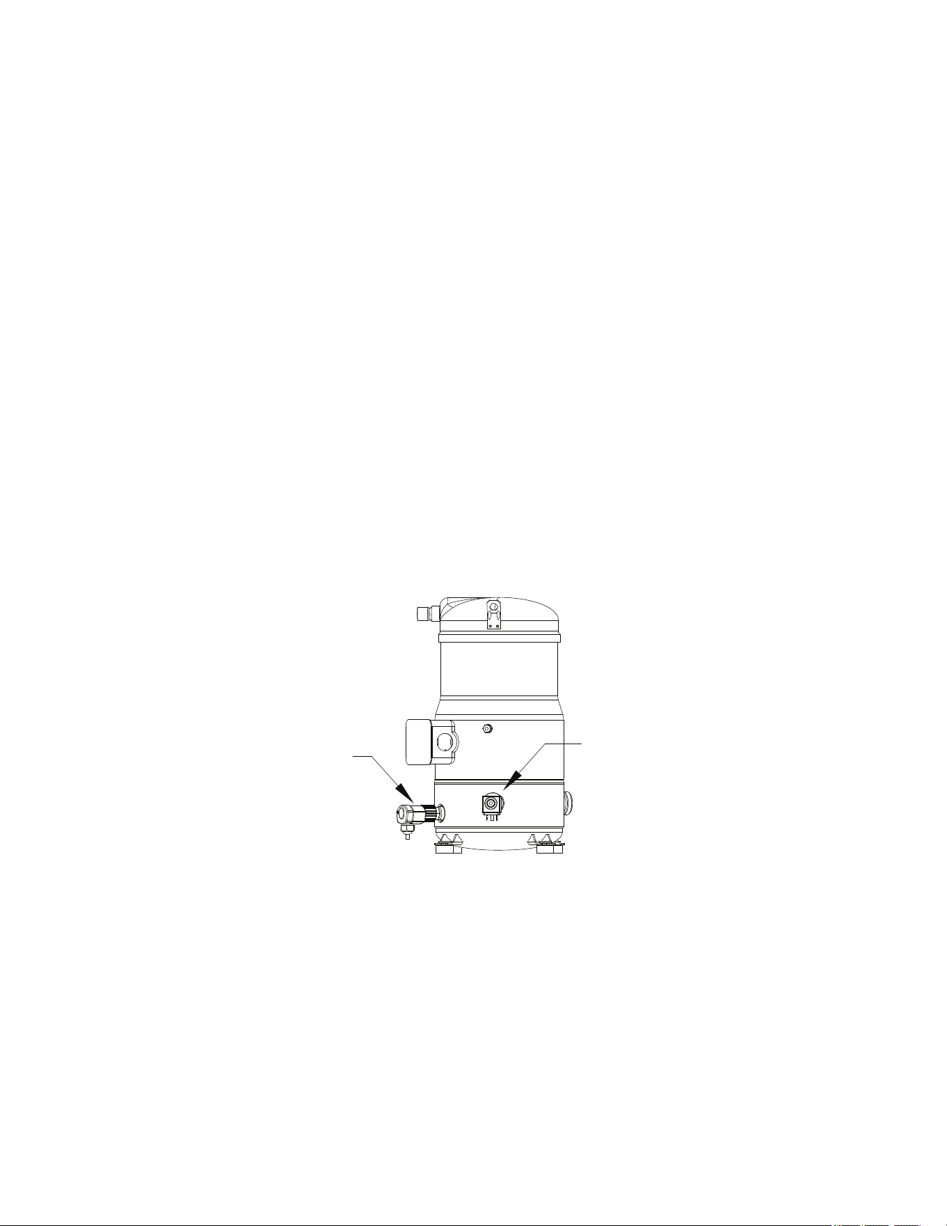
53
Compressor VZH 088/117/170
When oil return management is enabled, the frequency converter performs an oil boost when the
compressor is below 3000 RPM (100 Hz). The oil boost will happen every 60 minutes for 30 seconds when
the compressor speed is below 3000 RPM (100 Hz). When “Hands On” mode is selected, the oil return
management will not be active, even if the parameter is set to be on. The minimum/maximum speed for the
compressor is 1500 RPM (50 Hz)/6000 RPM (200Hz).
Oil boost – This function is controlled by the Variable Frequency Drive converter (VFD-02) to return oil
from the system to the compressor when oil balance cannot be reached or maintained in a defined time
period.
Oil solenoid – The MUA board controls the oil solenoid (Figure 30), which will then actuate the valve. This
solenoid valve set up helps optimize the oil circulation and improves efficiency of the compressor at all
running speeds. Control parameters are factory preset but are accessible on the parameter list as read-
only values.
Oil level sensor – This sensor (Figure 30) is an optical sensor that monitors the compressor’s internal oil
level. The sensor will send a signal to the VFD controller. A warning will be displayed on the HMI if a low oil
level condition exists. If the oil level is low, the system will enter a secondary oil boost. If the oil level is still
low after this boost cycle, the system will shut down and display a fault.
If the oil level is low, add oil as necessary when the compressor is idle. Use POE oil from new containers.
DO NOT CONTAMINATE THE OIL. Connect an oil hand pump to the Schrader valve connection on the
compressor. Carefully add oil until the oil level sensor is satisfied after the compressor has been off for at
least 5 minutes. Repeat until the oil level sensor is satisfied for at least 30 minutes of unit operation.
Figure 30 - Oil Level Sensor and Solenoid
Oil
Solenoid
Oil Level
Sensor
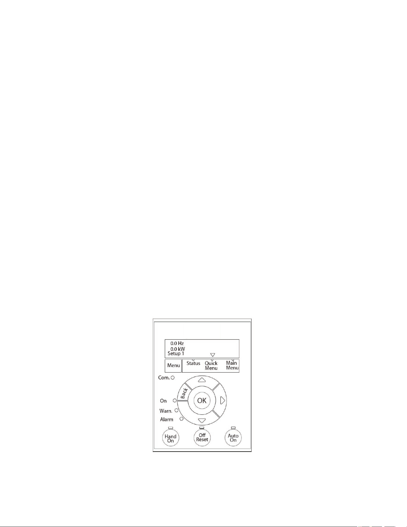
54
Compressor Drive Information
Refer to Figure 31 for CDS 803 controller interface. Refer to Figure 32 for CDS302/303 controller
interface.
CDS803 Quick Menu Navigation
The parameter setting for the compressor drive is factory set and should not be adjusted unless specified
by a service representative. If replacing the compressor drive, verify the settings match the compressor
drive parameter settings. If settings need to be programmed, proceed with the following:
• Press “Menu” to enter the “Quick Menu.”
• Press [▼] to select “Compressor Function.”
• Press “OK” to enter parameter screen.
• Press “OK” to enter and edit the parameter. Use [▲] [▼] to adjust the parameter to the factory settings.
Press “OK” to set parameter.
• Use the VFD schematics to locate the parameters that will need to be adjusted.
CDS803 Main Menu Navigation
“Main Menu” is used for access to and programming of all parameters. The Main Menu parameters can be
accessed readily by using the password. See VFD schematic for password.
For most Compressor Drive applications, it is not necessary to access the Main Menu parameters, but
instead, the Quick Menu provides the simplest and quickest access to the typical required parameters.
The Main Menu accesses all parameters.
• Press [Menu] until indicator in display is placed above “Main Menu.”
• Press [▲] [▼] to browse through the parameter groups.
• Press “OK” to select a parameter group.
• Press [▲] [▼] to browse through the parameters in the specific group.
• Press “OK” to select the parameter.
• Press [▲] [▼] to set/change the parameter value.
Press “Back” to go back one level.
NOTE: Contact Factory Service Department if more information is needed.
Figure 31 - CDS 803 Interface Controller
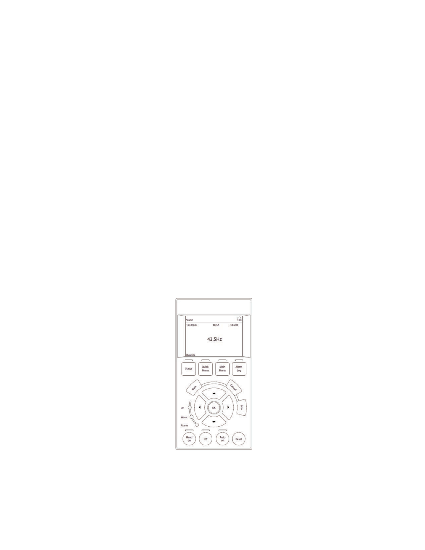
55
CDS302/303 Quick Menu navigation
The parameter setting for the compressor drive is factory set and should not be adjusted unless specified
by a service representative. If replacing the compressor drive, verify the settings match the compressor
drive parameter settings. If settings need to be programmed, proceed with the following:
• Press ‘Quick Menus.’
• Press the down arrow to select ‘Compressor Functions.’
• Press ‘OK’ to enter the parameter screen.
• Use the arrow keypad to select parameters. Press ‘OK’ to enter the parameter screen.
• Press ‘OK’ to enter and edit the parameter. Use the arrows keypad to adjust the parameter to the
factory settings. Press ‘OK’ to set parameter.
• Use the VFD schematics to locate the parameters that will need to be adjusted.
CDS302/303 Main Menu
In the Main menu mode, the parameters are divided into groups. Use the navigation keys for selecting a
parameter group.
After selecting a parameter group, select a parameter with the navigation keys. The middle section on the
display shows the parameter number and name.
The procedure for changing data is the same in both the Quick menu and the Main menu mode.
Press “OK” to change the selected parameter. The procedure for changing data depends on whether the
selected parameter represents a numerical data value or a text value.
Some of the parameters cannot be changed from the LCP. These parameters are defined by the
compressor choice made in 1-13 Compressor Selection. The parameters come up as “Read-only.”
NOTE: Contact Factory Service Department if more information is needed.
Figure 32 - CDS 302/303 Interface Controller
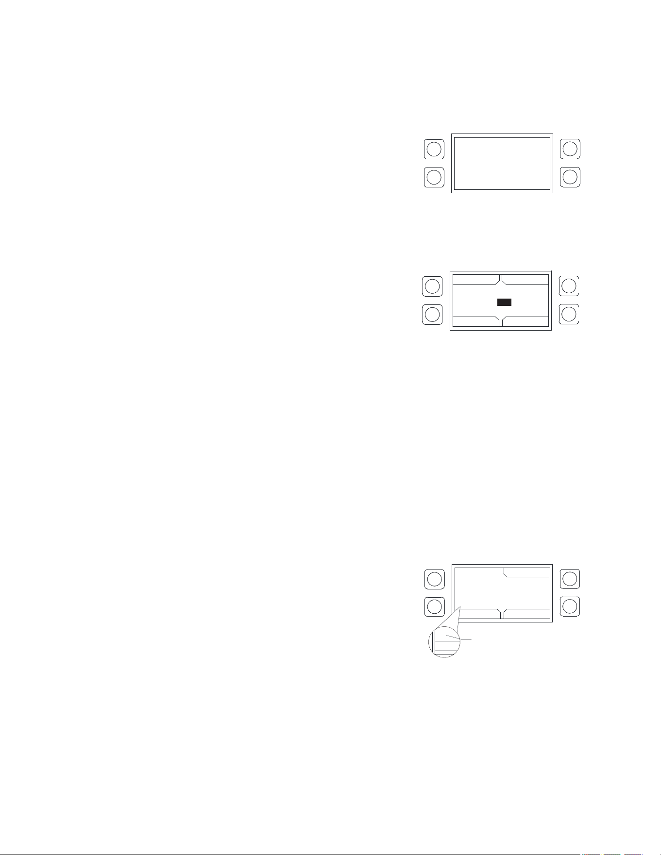
56
OPERATION
HMI Configuration Menu Access
Figure 33 - HMI Screen
General Overview
The HMI allows the user to change parameters and options. The user
may use the HMI to view operating information regarding sensors,
temperatures, pressures, and fault history on the HMI screen
(Figure 33).
There are four buttons to navigate through the HMI screens.
NOTE: Buttons change functions during certain options and tests.
Verify the screen and buttons throughout the menu display.
Figure 34 - Save Screen
The user can access the HMI configuration screen by pressing the top
two buttons simultaneously. To exit this screen, simply press the
‘BACK’ button. When setting certain options or functions, pressing the
‘BACK’ button multiple times will bring up the save screen (Figure 34).
The user may select ‘YES’ to save the changes, select ‘NO’ to return to
factory settings or select ‘CANCEL.’ When selecting ‘CANCEL,’ any
changes made will not be saved, and the screen will return to the top
menu.
The HMI menu system allows full access to every configurable
parameter in the HMI. The parameters are factory configured to the
specific application. Parameters may need to be modified to fine-tune
automatic operation after the original setup.
Remote (HMI) Control Panel
On units shipped with a space HMI, a Cat 5 cable will need to be run from J4, J5, or J6 (refer to
schematics) on the main MUA Board to J2 on the HMI. If additional space HMIs have been added, they
can be daisy-chained from the first HMI. In the event there is a slave MUA board, HMIs can also be
powered from J1 or J2 of the slave board. An end of line resistor should be added to the last HMI in the
chain.
HMI Notification Letters
Figure 35 - Notification Letters
The HMI will display notification letters (Figure 35) when the unit is in a
specific status.
• B = Blower Start or Blower Stop Delay Active
• C = Compressor Min On or Min Off Timer Active. Displayed when
the unit loses a call for cooling or heating (heat pump) during the
compressor’s “Min ON” or “Min OFF” time.
• E = Economizer Function
• O = Compressor oil boost
• T = Throttle Mode Active
• D = Dehumidification mode. Displayed when in dehumidification.
• Δ = Dynamic SP applied
SPACE
70°F
OCCUPIED IDLE
BACK
ENTER
UP
DOWN
SAVE CHANGES?
CONFIRM
YES
TEMP +
TEMP -
OFF
01/01
FRI
B
HEAT
SPACE
09:49
AM
70°F
OFF
B
Notification
Letter Location
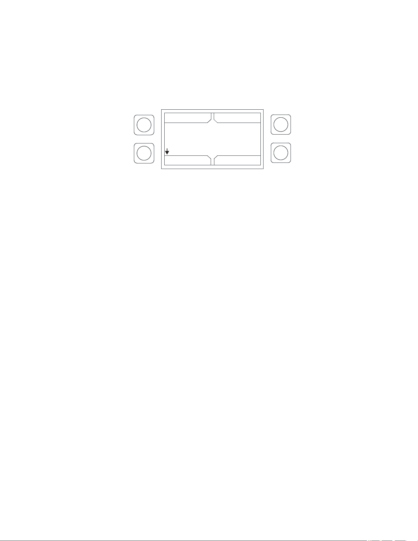
57
Configuring HMI
To enter the configuration menu (Figure 36), press the bottom two buttons simultaneously on the HMI
faceplate. In this menu screen, you may adjust Communication and Advanced Options, check Status, and
About information.
Figure 36 - Configuration Menu
Communication
Under the communication menu, the user may adjust the following settings:
• Modbus Address - Default is 55 for the first HMI. For every additional HMI, increase the address by
one. For example, if a second HMI is used, the Modbus Address should be 56. For a third HMI, the
Modbus Address should be 57.
• Baud - The baud rate address is 115200.
• Parity - Do not adjust this setting. The default setting should always be set to ‘EVEN.’
Advanced Options
Under advanced options, the user may adjust the following settings:
• Contrast - The user may adjust the setting from 0 to 10. Setting the contrast to 0 is the lowest setting
available, and 10 is the highest contrast setting available. The factory default contrast setting is 5.
• Audio Enable - User may set the audio to off.
• Dimming Enable - Default is set to Off. If set to On, the ‘HMI Dimming Timer’ option will be available.
• Set Time - The user may adjust dimming setting from 10-60 seconds. The default time is 30 seconds.
Status
User may monitor board temperature status, Uptime (how long the board has been active since last
restart), HW RH (HMI hardware humidity sensor), HW Temp (HMI hardware temperature sensor).
About
User may view SCADA Board Software Version, Modbus Address (assigned to HMI), Baud (115200).
MENU
ENTER
Communication
Advanced Options
Status
UP
DOWN
Configuration
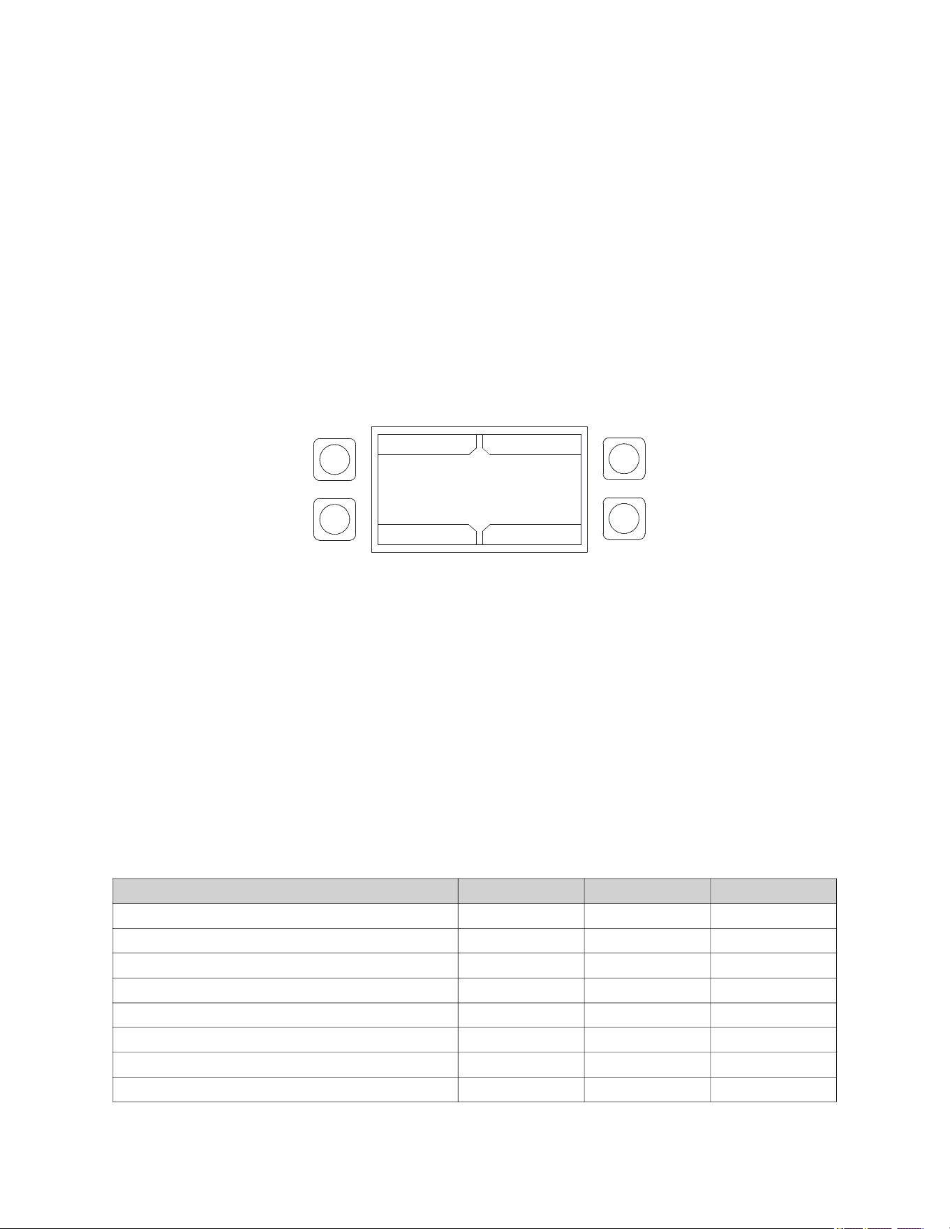
58
Scheduling
To set a schedule on the HMI (Figure 37), you must first enable scheduling: Factory Settings >
Occupied Scheduling > On
Set your sensor temperature set points for occupied and unoccupied schedules: User Settings > Temp
Set Points > (Varies)
Once scheduling is enabled, and the temperature set points are configured, you may enter your scheduled
days and times: User Settings > Scheduling
Figure 37 - Scheduling Screen
To adjust the settings, highlight the parameter and press ENTER.
• The first parameter to be highlighted will be the day. Press UP or DOWN to select the day an occupied
time schedule is required.
• Press ENTER to continue to set a start time. Press UP or DOWN to set start time.
• Press ENTER to set an end time. Press UP or DOWN to set end time.
The system will run between these days, time, and desired temperature settings. When in the
UNOCCUPIED setting, the system will run at the unoccupied temperature setting.
Fan Speed and Damper Position Presets
Table 13 outlines the aux pins on Connector J11 for preset settings associated with fan speed and damper
position found in Factory Settings > Unit Options.
NOTE: When dehumidification is enabled (Aux 1), fan or damper preset speeds will not work.
Schedule A Default Schedule B Default Schedule C Default
• Monday - Friday
8:00AM to 6:00PM
• Saturday and Sunday
Unocc
• Monday - Friday
Unocc
• Saturday and Sunday
Unocc
• Monday - Friday
Unocc
• Saturday and Sunday
Unocc
Table 13 - Aux Presets
Presets Aux 1 Aux 2 Aux 3
Normal Operation (Selected Blower Mode)
Fan Speed/Damper Position 1 X
Fan Speed/Damper Position 2 X
Fan Speed/Damper Position 3 X X
Fan Speed/Damper Position 4 X
Fan Speed/Damper Position 5 X X
Fan Speed/Damper Position 6 X X
Fan Speed/Damper Position 7 X X X
OCCUPIED SCHEDULING
MONDAY
UP
BACK
DOWN
ENTER
8:00AM TO 6:00PM
6:00PM TO 6:00PM
A
B

59
Menu Descriptions
This section will explain the different menus, settings, and options available in the HMI. Refer to “Menu
Tree” on page 70 for default/range settings, and HMI screen navigation.
MENU SETTINGS
User settings – Allows the user to change or set certain temperatures and configurations on the unit. Any
changes within this menu do not require a reboot to take effect.
Factory settings – Requires a password to enter this menu (1111). These will be set job-specific from the
plant. Upon exiting factory settings, if certain settings are altered, the board will reboot itself.
Service settings – Requires a password to enter this menu (1234). This will allow a certified technician to
monitor the unit and test components in the system.
About - Unit type and software revision information.
USER SETTINGS
Temp Set Points – Some or all of these may not be available based on settings. If scheduling is enabled,
there will be occupied and unoccupied values for each set point. The user will be allowed to check or
adjust the set points for:
• Heating: Intake, Space, Discharge, Heat Min Discharge, Heat Max Discharge
• Cooling: Intake, Space, Discharge, Cool Min Discharge, Cool Max Discharge
• Humidity Ctrl: Intake Rel, Space Rel, Discharge Rel
• Options: Room Override, Intake Firestat, Discharge Firestat, Discharge Freezestat, Discharge Over-
heat, Cabinet Heat, Drain Heat, Economizer Temp Band, Economizer Temp, Economizer Enth Band,
Economizer RH, Comfort Reheat.
Scheduling – This menu will only show when the scheduling option is set to On.
• Schedule Times – Each day contains the option for three occupied time periods. If the time is scrolled
past 11:59 pm, it will display ‘UNOCC’.
• Copy Schedule – This will allow the user to copy an existing schedule from one day of the week to
individual days in the week, to Week Days, or All.
Fan Speed – Enabled when the supply fan is controlled by a VFD or ECM. The range of this menu is lim-
ited by the min and max set points under factory settings. When the fan is set to VFD, the settings will be
displayed in Hertz. When the fan is set to ECM, the PWM percentage will be displayed. When occupied
scheduling is set to On, occupied and unoccupied settings are available.
Outdoor Air Setting – Enabled when the outdoor air is set to percentage/voltage or scheduled control.
Limited by min and max outdoor air percentages/voltages located under factory settings.
Compressor Freq – Allows user to set desired frequency. This is available when the compressor control
is set to manual.
Man Cond Fan Speed
• Heat – Enabled when heat pump condensing fan mode is set to manual, you may select the % the
fans will operate at.
• Cool – Enabled when cooling condensing fan mode is set to manual, you may select the % the fans
will operate at.
Pressure Config – Adjustable pressure set points for building static pressure.
Single Zone VAV - When single zone VAV is enabled to the blower, damper, or both, depending on set-
tings, will modulate linearly between min and max discharge.
• Blower Speed Heat - Min/Max stage settings for blower speed in heating mode.
• Damper Pos Heat - Min/Max settings for damper position in heating mode.
• Blower Speed Cool - Min/Max stage settings for blower speed in cooling mode.
• Damper Pos Cool - Min/Max settings for damper position in cooling mode.
Dry Mode Config – The user will be allowed to check or adjust the set points/limits when the option is
enabled.

60
USER SETTINGS
ERV Settings – Allows access to Energy Recovery Ventilator (ERV) settings.
• ERV Wheel – Speed percentage setting for ERV wheel operation.
• ERV Exhaust Fan – Adjustable building pressure set points, manual, or differential set point. Values
dependent on ERV exhaust fan configuration.
• ERV Wheel Cleaning – Manual control allows On/Off. Auto allows for a timed scheduled cleaning.
When On, countdown timer will be active.
Dynamic SP Diff – Temperature differential for dynamic set point change.
Dynamic SP Offset – Temperature amount that will change per differential.
Dynamic Heat OA – Outdoor air dynamic heat set point.
Dynamic Cool OA – Outdoor air dynamic cool set point.
CO2 Control Config – CO2 Parts Per Million (PPM) set points and sensor settings.
• PPM Low/High – CO2 Parts Per Million (PPM) threshold set points for the space, used in CO2 Over-
ride.
• PPM Limit - CO2 Parts Per Million (PPM) threshold limit set point.
• Sensor Min/Max – Set minimum and maximum range setting for CO2 sensor.
Active Faults – Contains the current faults on the board.
Fault History – Displays time-stamped history of the last 20 faults, most recent fault showing first.
Reset Lockouts – Displayed when a lockout fault has occurred. Enter menu to reset fault(s).
FACTORY SETTINGS NOTE: Password to enter factory settings menu is 1111
Temperature Control – The MUA board monitors temperature control components.
• Temperature Mode – There are five options for controlling the output of the unit in heat/cool tempering
mode. These options are Discharge/Space/Analog/Direct Digital Control (DDC). Refer to “Sequence
of Operation” on page 85.
• Activate Based On – The unit can be set to “Activate On” during the following temperature readings:
Intake/Space/Both/Either/Stat (field installed thermostat). These settings can be altered for occupied
and unoccupied preferences.
• Construction Mode – Configurable option for units used in construction settings.
Heating Config – Allows the user to set various heating configurations.
• Heating Type – Selectable range: None, Indirect, Heat Pump, Electric, HP & Ind, HP & Elec, HP or
Elec.
• Heat Hyst
• Space – The space tempering sensor must go this amount of degrees above the set point before
heating turns off.
• Intake – The intake tempering sensor must go this amount of degrees above the set point before
heating turns off.
• 2nd Disch Sensor – On/Off selection. When an additional thermistor is added, the two thermistor
readings will be averaged together.
• Input Source – This lets the board know what signal (volts or milliamps) to expect from the analog
control system.
• Gas Heat Config
• # of Heat Stages – Default is set to 0 for units without gas heat. Select 1 for units equipped with gas
heat. Select 2 for units equipped with gas heat and high turndown.
• Relay Delays
• ROT – This is the time after a furnace loses a call for heat before the furnace shuts down.
• RCT – If the heat stage value is greater than 1, the user may adjust Relay Close Time (RCT)
delay for stages.
• Powervent Config – The power vent operation may be set to operate in modulation mode or in an
ON/Off mode. The available settings are Triac Mod, PV On Off, or PWM Mod.

61
FACTORY SETTINGS NOTE: Password to enter factory settings menu is 1111
• Furnace Float – Monitors the water level from condensation in the drain pan. Default is Off, select
On if a switch is installed on the unit. Required on high-efficiency furnaces.
• High Turndown – Enable this option to On when the unit is equipped with a split furnace.
• Heat Pump Config
• Cond Fan Config
• Mode – The condensing fans can operate from one of the following modes: Outside Temperature
Differential or Manual.
• OA Diff – If the outside temperature differential is selected, the default temperature is set at 15°F.
• Min Speed/Max Speed – The minimum and maximum rate the condensing fans will operate.
Minimum default is 15%. Maximum default is 100%.
• Defrost Config
• Mode – This allows for the unit to defrost the outdoor coil in the case of freezing ambient condi-
tions. User may set defrost method to Off/Timer/PressTemp.
• Time Off – If the timer option is selected, the time off default is 15 minutes.
• Time On – Minutes between defrost cycles if in timer or temperature mode. Default time is 10
minutes.
• Min Suc PS – If the pressure/temperature defrost setting is selected, the suction pressure default
is set to 40 psi.
• Min Suc Temp – If the pressure/temperature defrost setting is selected, the suction temperature
default is 5°F.
• Comp Max Freq – Limits the maximum run speed of the compressor.
• HP Set Points
• Min OA Temp – The heat pump will shut off at the set minimum temperature. The default tem-
perature setting is 45°F.
• Max OA Temp – The heat pump will shut off at the set maximum temperature. The default tem-
perature setting is 75°F.
• Superheat – Monitors what state the refrigerant is in as it leaves the evaporator coil. The super-
heat default setting is 20°F.
• High Ambient – Option optimizes heat pump operation when outside temperatures increase to
avoid high head pressures from the compressor.
• Cabinet Hyst – This is the differential for the cabinet heater. The outdoor air temp must reach this
many degrees above the activation set point to turn off.
• Freezestat Timer – The discharge temp must stay below the freezestat set point for this amount of
time before the unit will lock-out on freeze stat.
• Heat + Dehumid – Allows dehumidification to run while the unit is heating.
Cooling Config – Allows the user to set various cooling configurations.
• Min Cool (OA) Temp – Cooling will not activate when outdoor air temperature is below this set point.
Default is 55°F.
• Min Cool Intake Temp – Cooling will not activate when intake temperature is below this set point.
Default is 55°F.
• Cond Fan Config
• Mode – The condensing fans can operate from one of the following modes: Outside Temperature
Differential or Manual.
• OA Diff – If the outside temperature differential is selected, the default temperature is set at 20°F.
• Min Speed/Max Speed – The minimum and maximum rate the condensing fans will operate. Mini-
mum default is 15%. Maximum default is 100%.
• Comp Max Freq – Limits the maximum run speed of the compressor.

62
FACTORY SETTINGS NOTE: Password to enter factory settings menu is 1111
• Cool Hyst
• Intake – The intake tempering sensor must change this amount of degrees below the set point
before cooling turns off. Default is 3°F.
• Space – The space tempering sensor must change this amount of degrees below the set point
before cooling turns off. Default is 1°F.
• Reheat Config
• Reheat Mode – RH&DP, DP, RH, VP, VP&RH, Off selection. When RH/DP is selected, software will
monitor both dew point and relative humidity for reheat activation. When only DP is selected, soft-
ware will monitor dew point for reheat activation. When only RH is selected, software will monitor rel-
ative humidity for reheat activation. When only VP is selected, software will monitor vapor pressure
for reheat activation. When VP&RH is selected, software will monitor both vapor pressure and rela-
tive humidity for reheat activation. When Off is selected, reheat will not be active.
• Valve Limits – Min and max settings for reheat valve position.
• RH/DP Input Mode – When reheat mode is set to RH/DP, the user may select between DP or RH.
• Differentials
• Space – Reheat will activate if the cooling mode is set to SPACE, the inside coil temperature and
the desired reheat set point is less than the intake dew point minus the space differential. Default
is 2°F.
• Discharge – Reheat will activate if the cooling mode is set to DISCHARGE, the inside coil tem-
perature and the desired reheat set point is less than the intake dew point minus the discharge
differential. Default is 2°F.
• RH Hyst
• Intake – The intake RH/DP must go below the intake RH/DP set point plus intake reheat hyst
before reheat turns off.
• Space – The space RH/DP must go below the intake RH/DP set point plus intake reheat hyst
before reheat turns off.
• Dew Point Adjust – Occ and Unocc settings for dew point adjust. This value determines what dew
point the unit will cool to before reheating occurs. If the reheat dew point adjust is set to 5°F, and the
reheat set points’ dew point is set to 50°F, the unit will cool the air to 45°F before reheating.
• Low Load – When On, if the unit is only dehumidifying and heating shuts cooling down, the unit
should not try to cool again via RH activation until there is a call for cooling from temp activation.
When Off, if the unit is only dehumidifying and heating shuts cooling down, the unit can try to cool
again via RH activation.
• Reheat Valve Model – Valve model selection.
• Reheat Optimization – On/Off option. When active, the condenser fan speed will be reduced when
outdoor air conditions limit reheat capacity.
• Aux Reheat – On/Off option. Activates auxiliary heat source (gas or electric) when the unit is not
meeting heating set point. A ON/Off timer setting will be active when Aux Reheat is On.
• Dual Reheat – Allows hot gas reheat and auxiliary heat to operate at the same time.
• 2nd Evap Sensor – On/Off option. When active, the evap temperature will be averaged between
the two sensors.
• Dynamic DP Config – On/Off option. Adjusts target evaporator temperature when the space/dis-
charge humidity set point is satisfied to help reduce unit’s energy usage.
• Min Adj/Max Adj – Minimum and maximum DP adjustment range. Minimum adjustment range
default setting for Space is 5°F/Discharge is 1°F. Maximum range adjustment default setting for
Space is 10°F/Discharge is 5°F. Occ and Unocc settings are available.
• Reheat Oil Boost – When an oil boost is active, the reheat valve will move to set position.
• Comfort Reheat – On/Off option. When On, reheat will be utilized when mechanical cooling cannot
achieve max cool discharge.

63
FACTORY SETTINGS NOTE: Password to enter factory settings menu is 1111
• Superheat Set Point – Monitors what state the refrigerant is in as it leaves the evaporator coil. The
superheat default setting is 20°F.
• Overheat Timer – The discharge temperature must not exceed the set point for 30 minutes (default),
or the unit will shut down. When in cooling, the unit will wait for the “Comp Min Off Time” for the com-
pressor, then re-attempt to cool again. If the overheat stat fails again, everything will shut down and
display the fault “Overheat Stat Failure.”
• Low Ambient Cooling – On/Off option. When enabled, the unit to adjust internal parameters and
allow cooling operation down to 0°F ambient.
• Act Temp – Low ambient logic will activate below this set point.
• EEV Pos – Sets min position for EEV during startup.
• EEV Control – Sets duration of minimum EEV position during startup.
• Thrttl Delay – Prevents low side throttle during startup.
• Cond Min/Cond Max – The minimum and maximum rate the condensing fans will operate at low
ambient conditions.
• Superht SP – Superheat target during extreme low ambient start-up.
• Superht Time – Timer for modified superheat target during start-up.
• Extreme Low Ambient – On/Off option. When enabled, the unit can adjust cooling operation down to
-25°F ambient.
• Act Temp – Extreme low ambient logic will activate below this set point.
• EEV Pos – Sets minimum position for EEV during startup.
• EEV Control – Sets duration of minimum EEV position during startup.
• Thrttl Delay – Prevents low side throttle during startup.
• Sol Active – A timer for the bypass solenoid to boost suction pressure on startup.
• Sol Delay – A delay timer before bypass solenoid opens after start-up.
• Cond Min/Cond Max – The minimum and maximum rate the condensing fans will operate at
extreme low ambient conditions.
• Supply Duct Adj – On/Off option. When set to On, the discharge temperature offset is used to ensure
there is no condensation on uninsulated supply duct(s).
• Adjust - The offset amount the discharge will be from space dew point. Default is 2°F.
Compressor Config – Allows the user to change or adjust compressor settings.
• Compressor Model – Allows user to select compressor model.
• Control Mode – Allows the user to turn the compressor on between manual or auto control.
• Max Discharge Temp – Limits discharge temperature out of the compressor.
• Comp Min Times
• Min On – Amount of time the compressor must stay on. Default is 10 minutes.
• Min Off – Amount of time the compressor is off after being active. Default 10 minutes.
• Oil Sensor – On/Off option. Default is On. If an oil sensor is present, leave option set to ON.
• Oil Boost Time – User may set boost option for compressor. Settings are OFF or 1-120 minutes.
• Pumpdown Sequence – On/Off selection. Used for compressor protection in an off-cycle. Before the
pumpdown sequence begins, an oil boost will run to return oil back to the compressor before shutting
down.
EEV Config – Allows user to set Electronic Expansion Valve (EEV) model and adjust EEV position values.
• EEV Model – Selectable range of EEV models.
• Min Value – User may adjust range between 0% to max value set point.
• Max Value – User may adjust between min value set point to 100%.
ERV Config – If the Energy Recovery Ventilator (ERV) option is enabled, this menu allows access to ERV
settings and parameters.

64
FACTORY SETTINGS NOTE: Password to enter factory settings menu is 1111
• Energy Recovery – On/Off selection. If the energy recovery option is set to ON, menus will be avail-
able to adjust various energy recovery settings.
• Recovery Act Control – Selectable control type and dead band for ERV operation.
• Wheel Model – Each ERV size has a dedicated model. The user may set the wheel model type.
• Wheel Control – Adjustable setting that allows auto or manual control.
• Monitoring Sensors – Values that are associated with the operation of the ERV. Sensor pressure val-
ues monitor how much dirt and debris are collected on the filters and wheel.
• Exhaust Fan Config – Control settings for the ERV’s exhaust blower.
• Control – Selectable control type for the exhaust blower.
• Staging – Selectable activation modes for the exhaust blower. Only available with certain modes.
• Min Speed Occ/Unocc – User may adjust range between 0% to max value set point. When occu-
pied settings are enabled, two set points will be available.
• Max Speed Occ/Unocc – User may adjust between min value set point to 100%. When occupied
settings are enabled, two set points will be available.
• Purge Speed – Fixed speed the exhaust fan will operate when purge is activated.
• Low PS Lim – Low pressure limit setting for building differential pressure.
• High PS Lim – High pressure limit setting for building differential pressure.
• Cycle Time – Cycle time is the time between two consecutive readings.
• PS KP – Proportionally constant value for static pressure measured in V/sec.
• PS Hyst – Building pressure must go above or below hysteresis value for fan adjust accordingly.
• S REF KP – Proportionally constant value for supply fan pressure measured in V/sec. Only dis-
played when Exhaust Fan Control is set to supply reference.
• S REF DB – Defines the limits the unit will adjust to keep supply fan reference. Only displayed when
Exhaust Fan Control is set to supply reference.
• S REF SP – If the pressure difference between the supply and exhaust is greater/less than this set
point, the MUA board will attempt to adjust the output voltage until it matches the supply reference
set point.
• EF Comm – ERV communication loss, dictates functionality of exhaust fan when communication is
lost between exhaust fan and ERV.
• Wheel Size – Direct drive wheel size selection. The wheel size selection will be utilized for CFM
monitoring. Models available are 11, 13, 15, 18, 20, 24, 30, 36, 16Z, 18Z, 20Z, 22Z, 25Z, 28Z.
• Defrost Control – Optional monitoring and wheel control that will keep frost from forming, or melt the
frost if it has formed.
• Mode – Selectable activation type for frost control.
• OA Temp SP – If Temp/RH defrost is selected, the OA temp must be below set point for the ERV to
enter defrost mode.
• EA Temp SP – If Temp/RH defrost is selected, the EA temp must be below set point for the ERV to
enter defrost mode.
• RA RH SP – If Temp/RH defrost is selected, the RA RH must be above set point for the ERV to
enter defrost mode.
• On Time – Time setting in which the enthalpy wheel spins at the defrost wheel speed setting.
• Off Time – Time setting the ERV cannot activate into a defrost cycle after a cycle has completed.
• Speed – Adjustable speed which the user may set the enthalpy wheel speed during defrost cycle.
• Wheel Cleaning – Wheel cleaning settings.
• Mode – Selectable activation modes for wheel cleaning cycle.
• On Time – Amount of time the cleaning cycle is on when activated.
• Off Time – Amount of time that if the ERV is continuously off will activate a cleaning cycle.
• Min OA Damper Pos – Adjustable set point for the damper to activate.

65
FACTORY SETTINGS NOTE: Password to enter factory settings menu is 1111
• Staging Control – Adjustable time value that corresponds to the staging of the ERV and the Dedi-
cated Outdoor Air System ( DOAS) unit.
Occupancy Config
• Scheduling – This menu is where scheduling may be turned On or Off. Default is Off.
• Override – Allows the user to override the current occupied settings. This is an On/Off option. Default
is Off.
Unit Options
• Board Config
• Unit Address – Modbus address of the MUA board.
• Startup Timer – Time upon power-up where the board will sit idle.
• Temp Units – Allows the user to set temperature range. Changing between the two will reset all set
points. The board will reset as well.
• HMI Config
• Number – The number of HMIs connected to the MUA board. Must always be at least one.
• Screensaver – This is an On/Off menu. Default is set to On. If set to Off, the home screen will not
time out to the screensaver.
• Average HMI – If there are multiple space HMIs connected, this menu allows you to select which
will be included in the space temperature and relative humidity averaging. If a thermistor or rela-
tive humidity sensor is connected into the ST screw terminals, it will automatically be averaged
into any HMIs included.
• Temp Stat # – On/Off option to turn on temperature averaging for wired HMI thermistors.
• Lock Screen – If the option is set to On, a password (9999) will be required when; screen saver
option is enabled or if any button functions are not pressed for 5 minutes.
• Scnsvr Date Time – User may select date, time, and/or temperature to display on the HMI when
screensaver is active.
• DDC Main Config
• Baud - The baud rate of the Modbus communications.
• Word Bits - The amount of data bits over Modbus communications.
• Parity - The parity selection for Modbus communications.
• Stop Bits - The stop bits selection for Modbus communications.
• Blower Config
• Blower Control
• 120V Contactor – 120V output on the MUA board to energize the coil of a contactor. This option
should be selected when the RTU is used in conjunction with a DCV package.
• ECP – This option should be selected when the RTU is used in conjunction with a DCV package.
• VFD Manual – HMI selectable VFD frequency.
• VFD Jog – For use with VFD using photohelic control. Uses the aux pins to control the VFD.
Powering “Aux 1” will speed the fan up, powering “Aux 2” will slow the fan down. When neither
“Aux 1” nor “Aux 2” are powered, the VFD will hold current speed.
• VFD 0-10V – For use when an external 0-10V signal is being provided to control the speed of the
VFD.
• VFD Pressure – For use with VFDs that use a pressure transducer (0-10V output).
• ECM (Electronically Controlled Motor) – HMI selectable supply fan rate.
• ECM 0-10V – For use when an external 0-10V signal is being provided to modulate the ECM sup-
ply output between min and max speed.
• ECM Pressure – For use with ECMs that use a pressure transducer (0-10V output).

66
FACTORY SETTINGS NOTE: Password to enter factory settings menu is 1111
• Blower Mode – If the “Occupied Scheduling” is set to On, the menu screen for the blower mode will
allow you to choose ON/AUTO/OFF for Occupied or Unoccupied. If the “Occupied Scheduling” is set
to Off, the menu screen for the blower mode will allow you to choose MANUAL/AUTO/OFF. In
blower auto mode, the blower will only run when it gets a call for heating/cooling. In blower on mode,
the blower will run as long as the fan button is enabled regardless of whether the unit is heating/
cooling. In blower off mode, powering the unit interlock pin will cause the blower to run.
• Airflow Proving – User can set unit to prove with airflow sensor located on the board.
• Blower Delay Enable – User may set the blower start/stop delay to Off/Both/Cool/Heat.
• Blower Delay Time – A time setting delay for the start or stop of the supply blower.
• Door Interlock – When enabled, a “Door Interlock” fault will display when the blower door is open
during normal operation.
• Blower Presets – User may set blower preset option On/Off.
• PWM Rate Limits – Range Min to Max settings for fan speed.
• VFD Direction – Sends a command to the VFD to run in forward or reverse.
• VFD Freq Limits – Range Min to Max settings for fan speed.
• Occ Fan Presets – After the blower has started, the blower setting will use the aux pins to drive the
preset occupied value. Refer to “Fan Speed and Damper Position Presets” on page 58.
• Unocc Fan Presets – Allows user to set unoccupied preset blower speed value.
• Occ PWM Presets – After the blower has started, the blower setting will use the aux pins to drive
the preset occupied value. Refer to “Fan Speed and Damper Position Presets” on page 58.
• Unocc PWM Presets – Allows user to set unoccupied preset blower speed value.
• Blower Pressure
• Cycle Time – Cycle time is the time between two consecutive readings.
• Static PS KP – Proportionally constant value for static pressure measured in V/sec.
• Static PS Hysteresis – This is the hysteresis band used for the static pressure (SP) set point.
• Purge Config
• Purge Button – On/Off selection. When enabled On, a purge button will be displayed on the HMI.
When the purge button is pressed, the damper will open to max outdoor air and turn on the exhaust
contactor.
• Purge Time – This is setting is adjustable from 1 – 120 minutes, default is 15 minutes. This is the
amount of time that the unit will run the purge process if the user does not stop the purge manually.
• Purge Speed – Default is 60 Hz. Adjustable between VFD Min and Max frequency. This is the
speed the blower will run during the purge cycle. ECM Purge Speed – Adjustable between PWM
Min and Max frequency. This is the speed the blower will run during the purge cycle.
• Dry Mode Config – On/Off selection. When enabled On, a dry mode button will be displayed on the
HMI. When the dry mode button is pressed, the blower will activate (if not already operating).
• Monitoring Sensors – On/Off selection for possible options:
• Outdoor Air Config
• Outdoor Air Control – Off, Manual, 2 Position, Outdoor Air %, Analog Control, Pressure,
100% OA.
• Outdoor Air Deadband – If the temperature difference between the outdoor and return sensor is
less than or equal to this set point, the MUA board will not attempt to adjust the output voltage until it
matches the outdoor air percentage set point. This setting only takes effect when either outdoor air
% or schedule is selected.
• Return As Space – Setting this to On will not require a space sensor or HMI. This setting will use
the return air thermistor (RT) in place of the space.
- Smoke Detector
- Filter Monitor
- Intake Firestat
- Discharge Firestat
- Freezestat
- Freezestat RA
- Overheat
- Low Gas Switch
- High Gas Switch
- CO Shutdown

67
FACTORY SETTINGS NOTE: Password to enter factory settings menu is 1111
• Outdoor Air Limits – Minimum and maximum settings for mixing box. Percentage or voltage based
on mixing box selection.
• Min/Max Outdoor Air % – Minimum and maximum allowed outdoor air percentage.
• Min Outdoor Air – Minimum allowed outdoor air voltage range.
• Max Outdoor Air – Maximum allowed outdoor air voltage range.
• Preset OA Values – On/Off option. If set to On, the voltage values equivalent to outdoor air percent-
age.
• Edit OA% Table – User may edit voltages for an equivalent to outdoor air percent table.
• Economizer Config – Refer to “Economizer” on page 91.
• Economizer Mode – Off, Fixed Dry Bulb, Diff (Differential) Dry Bulb, Fixed Enthalpy, Diff
Enthalpy.
• Disable Cooling – When the economizer is using an outside air % greater than this setting,
mechanical cooling will be disabled.
• Economizer Act – Option to set the economizer to activate on cooling only, or cooling and
blower.
• Damper Presets – This allows the user to set damper preset option On or Off.
• Occ Damper Presets – User may set occupied damper speeds. Refer to “Fan Speed and Damper
Position Presets” on page 58.
• Unocc Damper Presets – User may set unoccupied damper speeds.
• Room Override – On, Off option. If set to On, the unit will use the Room Override SP rather than Dis-
charge SP. This setting should only be used when heat tempering mode is set to “Discharge” and
“Activate Based On” is set to “Either.” When the space is calling for heat, it will use the Room Override
SP instead of Discharge SP to heat the space.
• Exhaust Contactor – This allows the user to assign a contactor for an interlocked exhaust fan. There
is an occupied and unoccupied setting for this.
• None
• Before Airflow: Exhaust fan will start before the airflow proving switch has been activated.
• After Airflow: Exhaust fan will start after the airflow proving switch has proved there is airflow.
• Exhaust On Smoke – Input that when enabled, if it receives a 120V signal from a fire system, will shut
down the supply fan and enable the exhaust contactor.
• Unit Heaters – On/Off options for Cabinet, Drain, and Crankcase heaters.
• Trouble Input – While connector J28 pin 3 receives 24 volts, the unit will act based on one of the fol-
lowing settings:
• Unit Off – Shuts down blower (heating/cooling will also shutdown). Bypass any timers.
• Both Off – Turn off/lockout heating and cooling. Bypass min on/off timers.
• Heat Off – Turns off/lockout heating.
• Cool Off – Turns off/lockout cooling. Bypass min on/off timers.
• Set Back – Forces unit to unoccupied state.
• Outdoor Reset – Allows access to setting option On/Off. Below are scenarios for Outdoor Reset func-
tionality.
- Discharge Heat Tempering: If outside air is below OA Reset Low set point, heat will discharge to
Reset Heat Discharge setting.
- Space Heat Tempering: If outside air is below OA Reset Low set point, space set point will adjust to
Reset Heat Space setting.
• Dynamic Set Point – Below are scenarios for dynamic functionality.
- When heating: If the measured outside air temperature is below the Dynamic Heat OA set point
minus the differential set point, the space or discharge set point will increase/decrease by the offset.
- When cooling: If the measured outside air temperature is above the Dynamic Cool OA set point
minus the differential set point, the space or discharge set point will increase/decrease by the offset.

68
FACTORY SETTINGS NOTE: Password to enter factory settings menu is 1111
• Single Zone VAV – The single zone VAV option can be set to Off, Blower, Damper, or Both.
• Blower Speed Heat/Cool – Unit may be set to Blower or Both (Heating/Cooling).
- For heating in blower setting, blower to modulate with the discharge temp min discharge, min
blower speed. Max discharge, max blower speed. Scaled linearly between min/max discharge to
min/max blower speed.
- For cooling in blower setting, blower speed will change depending on how many cooling stages
are active. Evap counts as 1st stage of cooling.
• Damper Pos Heat/Cool – Unit may be set to Blower or Both (Heating/Cooling).
- For heating in damper setting, damper to modulate with the discharge temp min discharge, min
damper position. Max discharge, max damper speed. Scaled linearly between min/max dis-
charge to min/max damper position.
- For cooling in damper position setting, damper position will change depending on how many
cooling stages are active. Evap counts as 1st stage of cooling.
• DD Wheel Size – Direct drive wheel size selection. The wheel size selection will be utilized for CFM
monitoring. Models available are 11,13, 15, 18, 20, 24, 30, 36, 16Z, 18Z, 20Z, 22Z, 25Z, 28Z.
• Dehumid Input – Option associated with units that contain reheat. Set to Off when the unit does not
contain reheat, set to On when unit contains reheat.
• CO2 Control Config – Monitors CO2 and will adjust blower speed/damper position depending on
CO2 set point.
• Override – The unit will try to maintain space CO2 Parts Per Million (PPM) levels based on min/max
threshold set points set by the user. The unit will modulate the blower/damper linearly between their
corresponding min/max settings.
• Threshold – CO2 Parts Per Million (PPM) maximum threshold set points for the space. When the
space CO2 PPM reading exceeds the threshold setting, the blower/damper will go to their max set-
ting.
Occpd Ovrd (Occupancy Override) Duration – Length of override timer. If override is active, it can be
manually stopped by pressing the end override button on the HMI. The default setting is 1 hour but can be
adjusted up to 16 hours.
Limit SP (Set Point) Adjust – This allows the user to change the current temperature set point through
the home screen. The range adjustment is 0-100 degrees. Default is 5°F. When the set point is set to 0°F,
the adjustment buttons (+/-) will not be visible.
Temp Ovrd Duration – Length of temperature override timer.
PID Config – Protected Parameters (DO NOT CHANGE THESE PARAMETERS)
Sensor Offsets:
• Dschrg Disp Offset – Displays offset for discharge temp. This can be used if actual discharge tem-
perature is measured differently from what is being displayed.
• Space Disp Offset – Displays offset for space temperature. This can be used if actual space tempera-
ture is measured differently from what is being displayed.
• Dschrg RH Offset – Displays offset for discharge humidity. This can be used if actual discharge
humidity is measured differently from what is being displayed.
• Space RH Offset – Displays offset for space humidity. This can be used if actual space humidity is
measured differently from what is being displayed.
SERVICE SETTINGS NOTE: Password to enter factory settings menu is 1234
Temperatures – User can monitor various temperature values.
RH Values – User can monitor various RH values.
Open/Closed Status – Menu to view the open/closed status of all inputs.
Variable Values – Allows the user to monitor all of the variable input and output values.
Blower VFD Status – Live parameter feedback from the supply VFD.

69
SERVICE SETTINGS NOTE: Password to enter factory settings menu is 1234
Comp VFD Status – Live parameter feedback from the compressor VFD.
Refridge Diag – This allows the user to monitor refrigerant components, pressures, and temperatures.
Outdoor Air Values – Displays the high/low airflow limits. The calculated actual outdoor air percentage
will also be displayed.
ERV Diagnostics – Displays ERV performance and diagnostic values.
• Current Performance – Overview of ERV state, ERV wheel speed, exhaust fan speed, and wheel dif-
ferential pressure.
• Temp and RH – Displays temperature and RH values for every quadrant. Also calculates enthalpy at
every point.
• ERV Pressure – Real time values for monitoring ERV pressure parameters. Stores based values for
pressure faults. These values can be adjusted manually or through the ERV calibration process.
Vapor Pressure – Displays vapor pressure readings.
ERV Exhaust CFM – Displays measured ERV CFM readings. This readout is only valid for units with
direct-drive wheels.
Supply CFM – Displays measured CFM readings. This readout is only valid for units with direct-drive
wheels.
Test Menu
• Test Fans – Off, All, Supply, Exhaust, Powered Exhaust, Cond Fans.
• Test Gas Heat – Contains high and low fire tests.
• Test Cool/HP – Test cooling or heat pump system. Adjustments and parameters can be monitored
during testing.
• Test Analog Heating – This test will simulate a voltage input from a BMS system. The test will begin
at 0 volts. The up and down buttons allow for modulation of input.
• Test Analog Cooling – This test will simulate a voltage input from a BMS system. The test will begin
at 0 volts. The up and down buttons allow for modulation of input.
• Evacuation Mode – Only to be used when working on the cooling system. All refrigeration valves in
the circuit will be open during evacuation.
• Test Options
• Test Cabinet Heater – Beginning this test will activate the cabinet heater on.
• Test Drain Heater – Beginning this test will activate the drain heater on.
• Test Crankcase Heater – Beginning this test will activate the crankcase heater on.
• Test OA Ctrl – Beginning this test will create an output to the outdoor air control. The test will begin
at 0 volts. The up and down buttons allow for modulation of the output.
• Test Freezestat – Test menu will allow user access to adjust set points to verify freezestat operation
in various types of ambient conditions.
Clear Fault History – This will clear the entire fault history. If there is an active fault when cleared, that
fault will show up until it is fixed.
Set Clock – Set day and time.
Calibrate Static PS – Calibrates pressure sensor. Must disconnect all pressure tubes before calibration.
Calibrate CFM – Calibrates pressure differential in the venturi to calculate approximate fan CFM. Must
disconnect all pressure tubes before calibration.
Calibrate ERV – Calibrates pressure differentials across all filters and energy wheel.
ERV Service Mode – Allows user to control damper, supply, and exhaust fans.
Update Factory Defaults – This allows the original factory default settings to be overridden. When con-
firming the updated settings, these settings will now be used when “Factory Reset” is needed.
Factory Reset – Will reset board to factory commissioned settings.
70
Menu Tree
NOTE: If scheduling is On, occupied and unoccupied settings will be available for some
INTAKE SET POINTS
SPACE SET POINTS
DISCHARGE LIMITS
HEAT (OCC/UNOCC)
HEAT (OCC/UNOCC)
HEAT MIN (OCC/UNOCC)
HEAT MAX (OCC/UNOCC)
COOL (OCC/UNOCC)
COOL (OCC/UNOCC)
RANGE: 0-110°F/(-18)-43°C
DEFAULT: 45°F/7°C
RANGE: 35-110°F/2-43°C
DEFAULT: 70°F/21°C
RANGE: 40-150°F/4-66°C
DEFAULT: 80°F/26°C
RANGE: 40-150°F/4-66°C
DEFAULT: 100°F/37°C
RANGE: 40-120°F/4-49°C
DEFAULT: 75°F/24°C
RANGE: 55-120°F/10-32°C
DEFAULT: 74°F/23°C
USER SETTINGS
TEMP SET POINTS
DISCHARGE SET POINTS
HEAT (OCC/UNOCC)
COOL (OCC/UNOCC)
RANGE: 40-150°F/4-66°C
DEFAULT: 80°F/27°C
RANGE: 40-80°F/4-26°C
DEFAULT: 55°F/13°C
HUMIDITY CTRL RH SET POINTS
RANGE: 0-100%
DEFAULT: 50%
COOL MIN (OCC/UNOCC)
RANGE: 40-80°F/4-26°C
DEFAULT: 55°F/13°C
COOL MAX (OCC/UNOCC)
RANGE: 40-80°F/4-26°C
DEFAULT: 70°F/20°C
INTAKE (OCC/UNOCC)
DSCHRG (OCC/UNOCC)
RANGE: 0-100%
DEFAULT: 50%
SPACE (OCC/UNOCC)
RANGE: 0-100%
DEFAULT: 60%
DP SET POINTS
RANGE: 38-75°F/2-24°C
DEFAULT: 55°F/13°C
INTAKE (OCC/UNOCC)
DSCHRG (OCC/UNOCC)
RANGE: 38-75°F/2-24°C
DEFAULT: 55°F/13°C
SPACE (OCC/UNOCC)
RANGE: 38-75°F/2-24°C
DEFAULT: 55°F/13°C
71
OPTION SET POINTS
ROOM OVERRIDE
FIRESTAT SET POINTS
FREEZESTAT SET POINT
CAB HEAT SET POINT
RANGE: 100-300°F/38-149°C
DEFAULT: 135°F/57°C
RANGE: 100-300°F/38-149°C
DEFAULT: 240°F/116°C
RANGE: (-40)-75°F/(-40)-24°C
DEFAULT: 35°F/2°C
RANGE: 0-40°F/(-18)-4°C
DEFAULT: 0°F/-18°C
RANGE: 40-150°F/4-66°C
DEFAULT: 90°F/31°C
INTAKE
DISCHARGE
FREEZESTAT
CAB HEAT
USER SETTINGS
TEMP SET POINTS
DRAIN HEAT SET POINT
RANGE: 35-45°F/2-7°C
DEFAULT: 35°F/2°C
DRAIN HEAT
OVERHEAT SET POINT
RANGE: 60-120°F/15-49°C
DEFAULT: 80°F/27°C
OVERHEAT
ECONOMIZER SETTINGS
TEMP SETTINGS
TEMP OCC/UNOCC
RANGE: 0-80°F/(-17)-27°C
DEFAULT: 60°F/16°C
BAND OCC/UNOCC
RANGE: 0-20°F/0-11°C
DEFAULT: 5°F/3°C
TOTAL BAND SETTINGS
RH OCC/UNOCC
BAND OCC/UNOCC
RANGE: 0-20°F/0-11°C
DEFAULT: 5°F/3°C
RANGE: 0-90%
DEFAULT: 50%
OA RESET LOW
OA RESET HIGH
RANGE: 35-110°F/7-43°C
DEFAULT: 45°F/7°C
RESET LOW
RANGE: 35-110°F/7-43°C
DEFAULT: 75°F/7°C
RESET HIGH
RESET HEAT DISCHARGE
RESET COOL DISCHARGE
RANGE: 40-150°F/4-65°C
DEFAULT: 90°F/32°C
HEAT DISCH
RANGE: 35-110°F/7-43°C
DEFAULT: 50°F/32°C
COOL DISCH
RESET HEAT SPACE
RESET COOL SPACE
RANGE: 40-150°F/4-65°C
DEFAULT: 90°F/32°C
HEAT SPACE
RANGE: 35-110°F/7-43°C
DEFAULT: 50°F/32°C
COOL SPACE
SCHEDULING
SCHEDULING TIMES
COPY SCHEDULE
START A/B/C - UNOCC/TIME
END A/B/C - UNOCC/TIME
MONDAY - SUNDAY
COPY FROM “DAY”
COPY TO “DAY”/WEEKDAYS/ALL
FAN SPEED (VFD)
FREQ
RANGE: MIN - MAX VFD HZ
DEFAULT: 60 HZ
FAN SPEED (ECM)
RATE OCC/UNOCC
RANGE: MIN - MAX PWM %
DEFAULT: 100%
OUTDOOR AIR SETTINGS
PERCENT or VOLTAGE
OCC/UNOCC
RANGE: 0-100% or 0-10V
DEFAULT: MIN % or MIN V
COMPRESSOR FREQ
FREQ
RANGE: MIN - MAX HZ
DEFAULT: VARIES
COMFORT REHEAT
RANGE: 1-20°F/1-10°C
DEFAULT: 2°F/1°C
TEMP DIFF
RANGE: 1-120 M
DEFAULT: 20 M
ON TIME
RANGE: 1-120 M
DEFAULT: 20 M
OFF TIME
VZH044 and smaller: Range 30-200Hz.
Default 200Hz
VZH052 - VZH065: Range 50-330Hz.
Default 330Hz
VZH088 and larger: Range 50-330Hz.
Default 200Hz
72
USER SETTINGS
ACTIVE FAULTS
DISPLAYS ACTIVE FAULTS
FAULT HISTORY
DISPLAYS UP TO
20 FAULTS
RESET LOCKOUTS
RESETS ACTIVE
LOCKOUTS
PRESSURE CONFIG
RANGE: - 0.0” - HIGH
DEFAULT: 0.00 "WC
LOW (OCC/UNOCC)
HIGH (OCC/UNOCC)
RANGE: LOW - 15.0
DEFAULT: 0.10 "WC
DYNAMIC SP DIFF
RANGE: 0-50°F/0-25°C
DEFAULT: 10°F/5°C
DYNAMIC SP OFFSET
RANGE: (-20)-20°F/(-11)-11°C
DEFAULT: 1°F/1°C
DYNAMIC HEAT OA
RANGE: 0-110°F/(-18)-43°C
DEFAULT: 30°F/-1°C
DYNAMIC COOL OA
RANGE: 35-110°F/2-43°C
DEFAULT: 80°F/27°C
DRY MODE CONFIG
RH OCC/UNOCC
DISCHARGE OCC/UNOCC
INTAKE OCC/UNOCC
RANGE: 20-80%
DEFAULT: 50%
RANGE: 40-150°F/4-66°C
DEFAULT: 90°F/13°C
RANGE: 35-110°F/2-43°C
DEFAULT: 45°F/7°C
CO2 CONTROL CONFIG
PPM LOW (OCC/UNOCC)
RANGE: 0 PPM - PPM HIGH
DEFAULT: 500 PPM
PPM HIGH (OCC/UNOCC)
RANGE: PPM LOW - 2,000 PPM
DEFAULT: 1,000 PPM
SENSOR MIN
SET RANGE TO CO2 SENSOR
MIN SETTING
SENSOR MAX
SET RANGE TO CO2 SENSOR
MAX SETTING
ERV SETTINGS
ERV EXHAUST FAN
ERV WHEEL CLEANING
SPEED OCC/UNOCC
RANGE: MIN - MAX FAN SPEED
DEFAULT: 75%
STATE
ON/OFF
DEFAULT: OFF
STATE ON
CLEANING ACTIVE
ENDS IN 60 S
MAN COND FAN SPEED
HEAT
COOL
RANGE: 0-100%
DEFAULT: 100%
RANGE: 0-100%
DEFAULT: 100%
Adjust OCC only if on schedule.
Adjust OCC only if on schedule.
ERV WHEEL SPEED
SPEED OCC/UNOCC
RANGE: 20-100%
DEFAULT: VARIES BY MODE
DIFF
OFFSET
HEAT OA
COOL OA
PPM LIMIT
RANGE: 1 - 2,499 PPM
DEFAULT: 1,000 PPM
SINGLE ZONE VAV
RANGE: MIN - MAX Hz
DEFAULT: 0/60 Hz
BLOWER SPEED HEAT
DAMPER POS HEAT
RANGE: MIN - MAX %
DEFAULT: 0/100%
RANGE: MIN - MAX Hz
DEFAULT: 0/60 Hz
BLOWER SPEED COOL
DAMPER POS COOL
RANGE: MIN - MAX %
DEFAULT: 0/100%
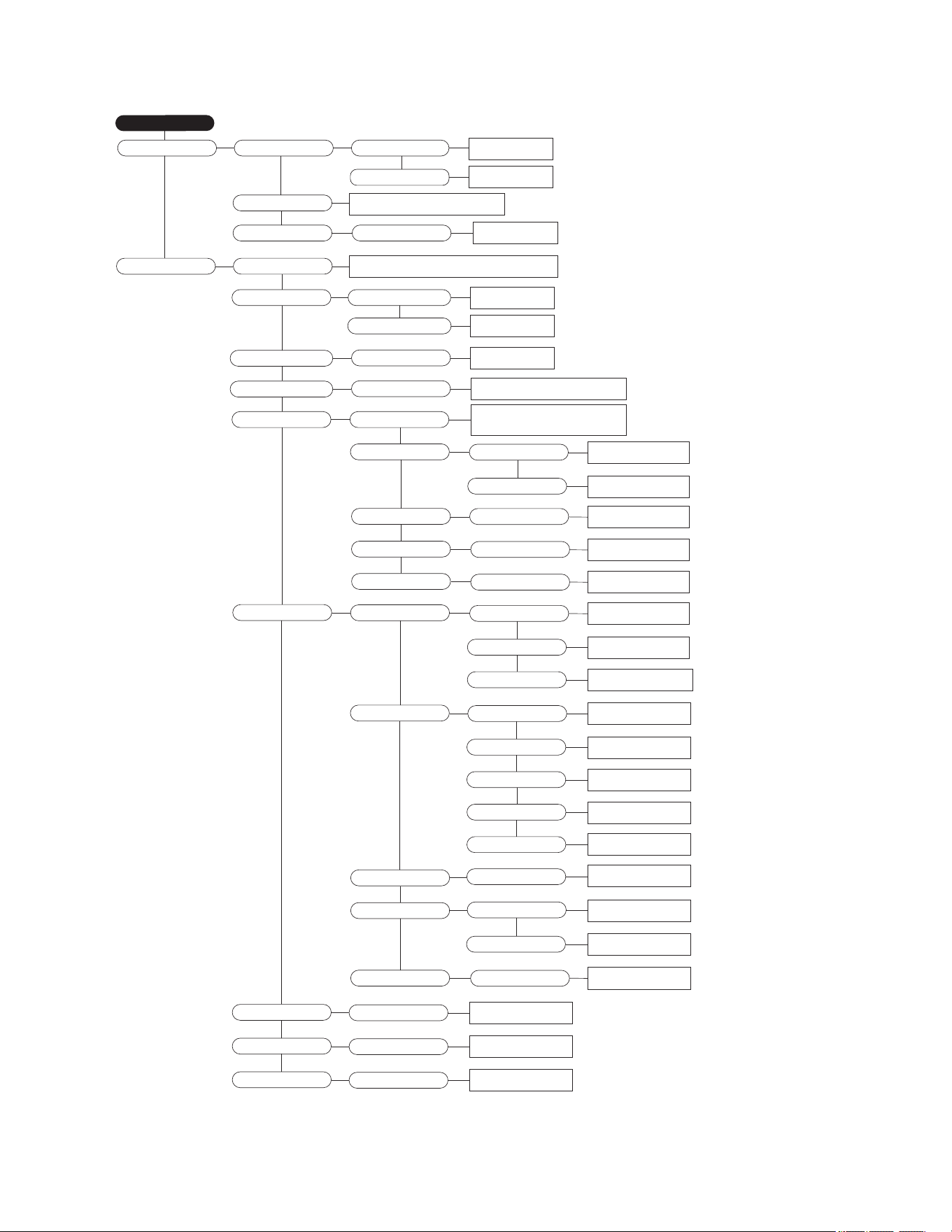
73
NOTE: Password to enter factory settings menu is 1111. If scheduling is On, occupied and
unoccupied settings will be available for some parameters.
TEMPERATURE CONTROL
FACTORY SETTINGS
TEMPERING MODE
ACTIVATE BASED ON
(OCC/UNOCC)
INTAKE/SPACE/BOTH/EITHER/STAT
HEATING CONFIG
# OF HEAT STAGES
DEFAULT: NO GAS HEAT 0
DEFAULT: GAS HEAT 1
DEFAULT: GAS HEAT HIGH TURNDOWN 2
HEATING TYPE
NONE (DEFAULT), INDIRECT, HEAT PUMP, ELECTRIC,
HP & IND, HP & ELEC, HP OR ELEC
HEAT PUMP CONFIG
HEAT HYST
SPACE
INTAKE
RANGE: 0-10°F/0-6°C
DEFAULT: 1
°F/1°C
HEAT (OCC/UNOCC)
COOL (OCC/UNOCC)
DISCHARGE, SPACE,
ANALOG, DDC
DISCHARGE, SPACE,
ANALOG, DDC
RANGE: 0-10
°F/0-6°C
DEFAULT: 3
°F/2°C
ENABLE
ON/OFF
DEFAULT: OFF
CONSTRUCTION MODE
GAS HEAT CONFIG
RELAY DELAYS
ROT
RANGE: 30-240 S
DEFAULT: 45 S
COND FAN CONFIG
DEFROST CONFIG
COMP MAX FREQ
HP SET POINTS
HIGH AMBIENT
POWERVENT CONFIG
TRIAC MOD, PV ON OFF,
PWM MODE
FURNACE FLOAT
ON/OFF
DEFAULT: OFF
RCT 2/3
RANGE: 30-600 S
DEFAULT: VARIES
HIGH TURNDOWN
ENABLE
ON/OFF
DEFAULT: OFF
MODE
MANUAL, OA TEMP DIFF
DEFAULT: OA TEMP DIFF
OA DIFF
RANGE: 0-40°F/0-22°C
DEFAULT: 15°F/3°C
MIN/MAX SPEED
RANGE: 0-100%
DEFAULT: MIN 15%/ MAX 100%
OFF, TIMER, PRESS/TEMP
DEFAULT: OFF
TIME OFF
RANGE: 0-100 M
DEFAULT: 15 M
TIME ON
RANGE: 5-100 M
DEFAULT: 10 M
MIN SUC PS
RANGE: 30-100 PSI
DEFAULT: 40 PSI
MIN SUC TEMP
RANGE: (-20)-40°F/(-29)-4°C
DEFAULT: 5°F/(-15)°C
FREQ
RANGE: MIN - MAX HZ
DEFAULT: VARIES
MIN OA TEMP
RANGE: 0-70°F/(-18)-21°C
DEFAULT: 45°F/7°C
SUPERHEAT
RANGE: 5-45°F/2-25°C
DEFAULT: 20°F/12°C
ENABLE
ON/OFF
DEFAULT: OFF
ENABLE
MODE
MODE
INPUT SOURCE
INPUT
0-10V (DEFAULT), 2-10V, 0-20mA, 4-20mA
CABINET HYST
HYST
RANGE: 1-10°F/0-6°C
DEFAULT: 1°F/1°C
FREEZESTAT TIMER
MINUTES
RANGE: 1-20 M
DEFAULT: 5 M
2ND DISCH SENSOR
ENABLE
ON/OFF
DEFAULT: OFF
HEAT + DEHUMID
ENABLE
ON/OFF
DEFAULT: OFF
VZH044 and smaller: Range 30-200Hz.
Default 200Hz
VZH052 - VZH065: Range 50-330Hz.
Default 330Hz
VZH088 and larger: Range 50-330Hz.
Default 200Hz
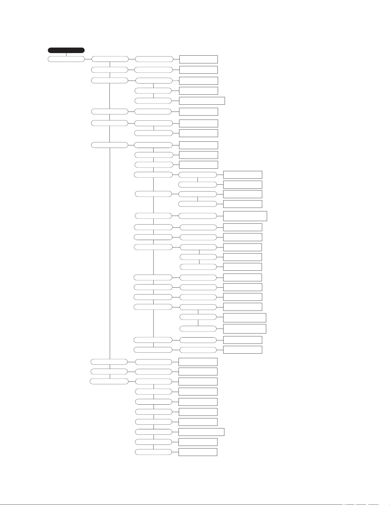
74
NOTE: Password to enter factory settings menu is 1111. If scheduling is On, occupied and
unoccupied settings will be available for some parameters.
COND FAN CONFIG
COMP MAX FREQ
MODE
MANUAL, OA TEMP DIFF
DEFAULT: OA TEMP DIFF
OA DIFF
RANGE: 0-40
°
F/0-22
°
C
DEFAULT: 20°F/11°C
MIN/MAX SPEED
RANGE: 0-100%
DEFAULT: MIN 15%/ MAX 100%
FREQ
RANGE: MIN - MAX HZ
DEFAULT: VARIES
COOL HYST
FACTORY SETTINGS
COOLING CONFIG MIN COOL OA TEMP
MIN COOL INTAKE TEMP
MIN TEMP
RANGE: 50-70
°
F/10-21
°
C
DEFAULT: 55
°
F/13
°
C
MIN TEMP
RANGE: 50-70
°
F/10-32
°
C
DEFAULT: 55
°
F/13
°
C
SPACE
INTAKE
RANGE: 0-10
°
F/0-6
°
C
DEFAULT: 1
°
F/1
°
C
RANGE: 0-10
°
F/0-6
°
C
DEFAULT: 3
°
F/2
°
C
REHEAT CONFIG
REHEAT MODE
OFF (DEFAULT) , RH, DP,
RH&DP, VP, VP&RH
DIFFERENTIALS
SPACE
DISCHARGE
RANGE: (-30)-30
°
F/0-17
°
C
DEFAULT: 2
°
F/1
°
C
RANGE: (-30)-20
°
F/0-11
°
C
DEFAULT: 2
°
F/1
°
C
RH HYST
INTAKE
SPACE
RANGE: 0-5%/
°
F (C)
DEFAULT: 1%/
°
F (C)
RANGE: 0-5%/
°
F (C)
DEFAULT: 1%/
°
F (C)
DEW POINT ADJUST
OCC/UNOCC DP ADJ
RANGE: 0-20
°
F/0-10
°
C
DEFAULT: DISCHARGE 5
°
F/3
°
C
SPACE 10°F/6°C
LOW LOAD
ENABLE
ON/OFF
DEFAULT: OFF
REHEAT VALVE MODEL
MODEL
MTW
DEFAULT: MTW
REHEAT OPTIMIZATION
ENABLE
ON TIME
ON/OFF
DEFAULT: OFF
RANGE: 0-10 M
DEFAULT: 3 M
OFF TIME
RANGE: 0-10 M
DEFAULT: 3 M
SUPERHEAT SET POINT
SP
RANGE: 5-45
°
F/2-25
°
C
DEFAULT: 20
°
F/12
°
C
OVERHEAT TIMER
MINUTES
RANGE: 1-60 M
DEFAULT: 30 M
LOW AMBIENT COOLING
ENABLE
ON/OFF
DEFAULT: OFF
RH/DP INPUT MODE
RH/DP
DEFAULT: DP
2ND EVAP SENSOR
ENABLE
ON/OFF
DEFAULT: OFF
AUX REHEAT
ENABLE
ON/OFF
DEFAULT: OFF
DYNAMIC DP CONFIG
ENABLE
ON/OFF
DEFAULT: OFF
MIN ADJ
RANGE: (-5)-30°F/(-3)-17°C
DEFAULT: DISCHARGE 1°F/1°C
SPACE 5°F/3°C
MAX ADJ
RANGE: (-5)-30°F/(-3)-17°C
DEFAULT: DISCHARGE 5°F/3°C
SPACE 10°F/6°C
ACT TEMP
RANGE: 45-60
°
F/7-15
°
C
DEFAULT: 55
°
F/13
°
C
COND MIN/MAX
RANGE: 0-100%
DEFAULT: MIN 9%/ MAX 100%
EEV POS
RANGE: 0-100%
DEFAULT: 35%
EEV CONTROL
RANGE: 0-600 S
DEFAULT: 180 S
THRTTL DELAY
RANGE: 0-900 S
DEFAULT: 180 S
SUPERHT SP
RANGE: 5-25
°
F/(-15)-(-4)
°
C
DEFAULT: 10
°
F/(-12)
°
C
SUPERHT TIME
RANGE: 0-600 S
DEFAULT: 180 S
VALVE LIMITS
RANGE: 0-100%
DEFAULT: MIN 15%/ MAX 100%
DUAL REHEAT
ENABLE
ON/OFF
DEFAULT: OFF
REHEAT OIL BOOST
VALVE POS
RANGE: 50-100%
DEFAULT: 50%
COMFORT REHEAT
ENABLE
ON/OFF
DEFAULT: OFF
When Low Ambient is configured On,
the Min Cool OA Temp settings are:
Range: (-5)-70°F/(-20)-21°C
Default: 0°F/(-17°C)
VZH044 and smaller: Range 30-200Hz.
Default 200Hz
VZH052 - VZH065: Range 50-330Hz.
Default 330Hz
VZH088 and larger: Range 50-330Hz.
Default 200Hz
When Extremer Low Ambient is configured
On, the Min Cool OA Temp settings are:
Range: (-25)-70°F/(-32)-21°C
Default: -25°F/(-32°C)
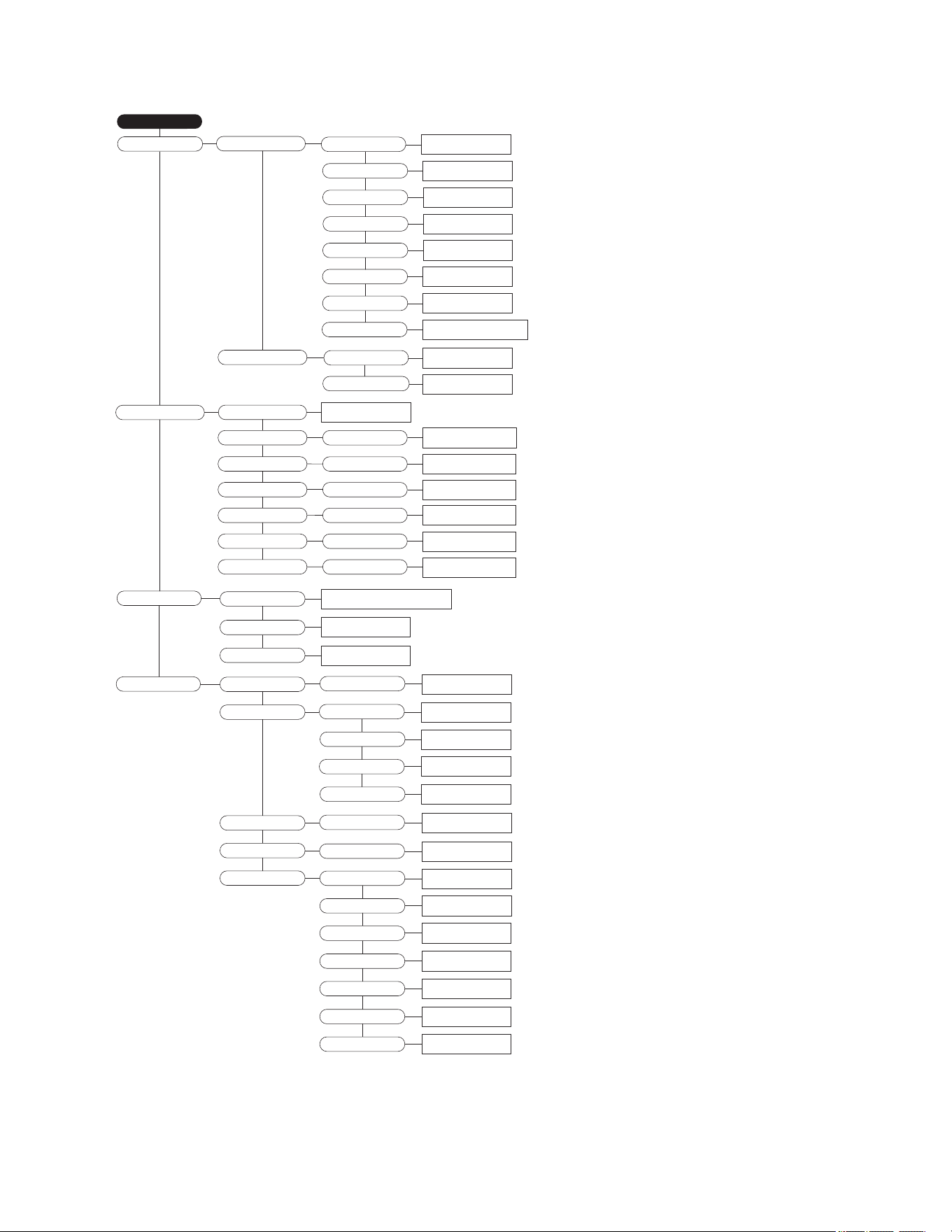
75
NOTE: Password to enter factory settings menu is 1111. If scheduling is On, occupied and
unoccupied settings will be available for some parameters.
MAX VALUE
RANGE: MIN-100%
DEFAULT: 100%
FACTORY SETTINGS
EEV CONFIG
EEV MODEL
MIN VALUE
RANGE: 0-MAX %
DEFAULT: 0%
SER-F, SER-C (DEFAULT), SER-D, SER-G,
ETS-12, ETS-24, ETS-25
ERV CONFIG
RECOVERY ACT CTRL
HEAT ACT
NONE, SENSIBLE,
ENTHALPY, BOTH
WHEEL MODEL
COOL ACT
NONE, SENSIBLE,
ENTHALPY, BOTH
DEADBAND (SENSIBLE)
DEADBAND (ENTHALPY)
RANGE: 0-5°F
DEFAULT: 2°F
RANGE: 0-3 BTU/LB
DEFAULT: 0.5 BTU/LB
MODEL
ERC 3628C, ERC 4136C,
ERC 5262C
WHEEL CONTROL
MODE
AUTO, MANUAL
DEFAULT: AUTO
MONITORING SENSORS
DOOR INTERLOCK
ON/OFF
DEFAULT: ON
CLOG FILTER
RANGE: 0-2”
DEFAULT: 0.25”
FRST WHEEL
RANGE: 0-2”
DEFAULT: 0.4”
EXH AIR PS
RANGE: 0.0-0.5”
DEFAULT: 0.1”
OA FR BASE
RANGE: (-5”)-5” wc
DEFAULT: 0.70” wc
RA FR BASE
RANGE: (-5”)-5” wc
DEFAULT: 1.50” wc
SA WD BASE
RANGE: (-5”)-5” wc
DEFAULT: 0.60” wc
ENERGY RECOVERY
ENABLE
ON/OFF
DEFAULT: OFF
COMPRESSOR CONFIG
COMPRESSOR MODEL
VZH028, 035, 044, 052, 065,
088, 117, 170
CONTROL MODE
MODE
MANUAL/AUTO
DEFAULT: AUTO
MAX DISCHARGE TEMP
MAX TEMP
RANGE: 212-302
°
F/100-150
°
C
DEFAULT: 212
°
F/100
°
C
COMP MIN TIMES
MIN ON/OFF
RANGE: 1-20 M
DEFAULT: 10 M
OIL SENSOR
ENABLE
ON/OFF
DEFAULT: ON
OIL BOOST TIME
MINUTES
RANGE: OFF/1-120 M
DEFAULT: OFF
PUMPDOWN SEQUENCE
ENABLE
ON/OFF
DEFAULT: ON
EXTREME LOW AMBIENT
ENABLE
ON/OFF
DEFAULT: OFF
SUPPLY DUCT ADJ
ON/OFF
DEFAULT: OFF
ADJUST
RANGE: 0-10°F (0-6°C)
DEFAULT: 2°F/1°C
ENABLE
ACT TEMP
RANGE: (-5)-5
°
F/(-21)-(-15
)°
C
DEFAULT: 0
°
F/(-18)
°
C
COND MIN/MAX
RANGE: 0-100%
DEFAULT: MIN 9%/ MAX 100%
EEV POS
RANGE: 0-100%
DEFAULT: 35%
EEV CONTROL
RANGE: 0-600 S
DEFAULT: 240 S
THRTTL DELAY
RANGE: 0-900 S
DEFAULT: 300 S
COOLING CONFIG
SOL ACTIVE
RANGE: 0-600 S
DEFAULT: 180 S
SOL DELAY
RANGE: 0-600 S
DEFAULT: 0 S
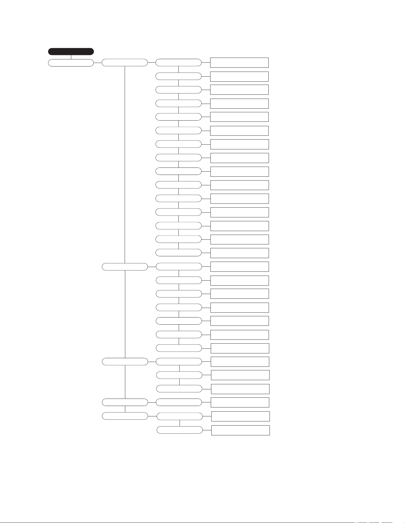
76
NOTE: Password to enter factory settings menu is 1111. If scheduling is On, occupied and
unoccupied settings will be available for some parameters.
FACTORY SETTINGS
ERV CONFIG
CONTROL
STAGING
MIN SPD OCC/UNOCC
MAX SPD OCC/UNOCC
SUPPLY REF, MANUAL (DEFAULT),
0-10V, STATIC PS
ERV ON, ALWAYS ON
DEFAULT: ALWAYS ON
RANGE: 0-100%
DEFAULT: 10%
RANGE: 0-100%
DEFAULT: 100%
PURGE SPEED
LOW PS LIM
RANGE: 0-100%
DEFAULT: 75%
RANGE: (-5”)-5” wc
DEFAULT: -0.25” wc
HIGH PS LIM
RANGE: (-5”)-5” wc
DEFAULT: 0.25” wc
CYCLE TIME
RANGE: 5-60 S
DEFAULT: 5 S
PS KP
RANGE: 0-20 V/S
DEFAULT: 8 V/S
PS HYST
RANGE: 0-100%
DEFAULT: 25%
DEFROST CONTROL
MODE
OA TEMP SP
EA TEMP SP
RA RH SP
TEMP/RH, OFF
DEFAULT: OFF
RANGE: (-40)-60°F
DEFAULT: 0°F
RANGE: (-40)-60°F
DEFAULT: 35°F
RANGE: 0-100%
DEFAULT: 30%
ON TIME
OFF TIME
RANGE: 0-60 M
DEFAULT: 10M
RANGE: 0-60 M
DEFAULT: 10M
SPEED
RANGE: 20-100%
DEFAULT: 20%
WHEEL CLEANING
MODE
MANUAL, AUTO, OFF
DEFAULT: MANUAL
ON TIME
OFF TIME
RANGE: 30-120 S
DEFAULT: 60 S
RANGE: 1-48 H
DEFAULT: 24 H
MIN OA DAMPER POS POSITION
RANGE: 0-10V or 0-100%
DEFAULT: 8 V or 80%
STAGING CONTROL
ERV TIME
DOAS TIME
RANGE: 0-60 M
DEFAULT: 2 M
RANGE: 1-60 M
DEFAULT: 15 M
EXHAUST FAN CONFIG
S REF KP
RANGE: 0.05-2 V/S
DEFAULT: 0.1 V/S
EF COMM
OFF/CONTINUE
DEFAULT: OFF
S REF DB
RANGE: 0.0-2”
DEFAULT: 0.0.5”
S REF DB
RANGE: 0.0-2”
DEFAULT: 0.0.5”
WHEEL SIZE
11D,13D, 15D, 18D, 20D, 24D, 30D,
36D, 16Z,18Z, 20Z, 22Z, 25Z, 28Z
77
NOTE: Password to enter factory settings menu is 1111. If scheduling is On, occupied and
unoccupied settings will be available for some parameters.
FACTORY SETTINGS
OCCUPANCY CONFIG
SCHEDULING
OVERRIDE
ON/OFF
DEFAULT: OFF
ON/OFF
DEFAULT: OFF
UNIT OPTIONS
BOARD CONFIG UNIT ADDRESS
ADDRESS 80
STARTUP TIMER
TIME
RANGE: 5-240 S
DEFAULT: 15 S
TEMP UNITS
MODE
FAHRENHEIT/CELSIUS
DEFAULT: FAHRENHEIT
HMI CONFIG
NUMBER
RANGE: 1-5
DEFAULT: 1
SCREENSAVER
AVERAGE HMI
ON/OFF
DEFAULT: OFF
ON/OFF
DEFAULT: OFF
LOCK SCREEN
ON/OFF
DEFAULT: OFF
BLOWER CONFIG BLOWER CONTROL
120V CONTACTOR, ECP, VFD MANUAL, VFD JOG, VFD 0-10V,
VFD PRESSURE, ECM, ECM 0-10V, ECM PRESSURE
BLOWER MODE
AUTO ( DEFAULT),
INTERLOCK, MANUAL
OCC/UNOCC
AIRFLOW PROVING
CONTROL
ONBOARD, REMOTE
DEFAULT: ONBOARD
PS SET POINT
RANGE: 0.05”-0.25” w.c.
DEFAULT: 0.15” w.c.
BLOWER DELAY ENABLE
START DELAY
HEAT, COOL, BOTH, OFF
DEFAULT: OFF
STOP DELAY
HEAT, COOL, BOTH, OFF
DEFAULT: OFF
BLOWER DELAY TIME
DELAY START
RANGE: 0-120 S
DEFAULT: 90 S
DELAY STOP
RANGE: 0-120 S
DEFAULT: 90 S
DOOR INTERLOCK
ENABLE
ON/OFF
DEFAULT: OFF
SCNSVR DATE TIME
DATE/TIME,
TEMP/DATE/TIME, TEMP
DDC MAIN CONFIG
BAUD
WORD BITS
9600, 19200, 38400,
57600, 115200
DEFAULT: 19200
8/9
DEFAULT: 9
PARITY
STOP BITS
1/2
DEFAULT: 1
NONE, ODD, EVEN
DEFAULT: EVEN
TEMP STAT #
ON/OFF
DEFAULT: OFF
78
NOTE: Password to enter factory settings menu is 1111. If scheduling is On, occupied and
unoccupied settings will be available for some parameters.
FACTORY SETTINGS
UNIT OPTIONS
BLOWER CONFIG
OCC FAN PRESETS
RANGE: 0-60Hz
DEFAULT: VARIES
UNOCC FAN PRESETS
RANGE: 0-60Hz
DEFAULT: VARIES
PRESET 1-7
PRESET 1-7
PRESET 1 = 40 Hz
PRESET 2 = 50 Hz
PRESET 3 = 0 Hz
PRESET 4 = 60 Hz
PRESET 5 = 0 Hz
PRESET 6 = 0 Hz
PRESET 7 = 0 Hz
FAN PRESETS DEFAULT
PRESET 1 = 80%
PRESET 2 = 90%
PRESET 3 = 0%
PRESET 4 = 100%
PRESET 5 = 0%
PRESET 6 = 0%
PRESET 7 = 0%
PWM PRESETS DEFAULT
OCC PWM PRESETS
RANGE: 0-100%
DEFAULT: VARIES
UNOCC PWM PRESETS
RANGE: 0-100%
DEFAULT: VARIES
PRESET 1-7
PRESET 1-7
RANGE
RANGE: +/- .25” w.c. or +/- 15” w.c.
DEFAULT: +/- .25” w.c.
PRESSURE CONFIG
SENSOR RANGE
CYCLE TIME
PS HYSTERESIS
PURGE CONFIG
PURGE BUTTON
ON/OFF
DEFAULT: OFF
ENABLE
PURGE TIME
RANGE: 1-120 M
DEFAULT: 15 M
DURATION
PURGE SPEED
RANGE: MIN-MAX Hz
DEFAULT: 60 Hz
VFD
DRY MODE CONFIG
ON/OFF
DEFAULT: OFF
ENABLE
ECM
RANGE: MIN-MAX%
DEFAULT: 100%
STATIC PS KP
RANGE: 5-60 S
DEFAULT: 5 S
CYCLE
RANGE: 0.10-0.15 V
DEFAULT: 0.15 V
KP
RANGE: 15-35%
DEFAULT: 25%
HYSTERESIS
BLOWER PRESETS
ENABLE
ON/OFF
DEFAULT: OFF
PWM RATE LIMITS
OCC/UNOCC MIN
RANGE: 0-MAX %
DEFAULT: 0%
OCC/UNOCC MAX
RANGE: MIN-100%
DEFAULT: 100%
VFD DIRECTION
DIRECTION
FORWARD/REVERSE
DEFAULT: FORWARD
VFD FREQ LIMITS
OCC/UNOCC MIN
RANGE: 0-MAX Hz
DEFAULT: 0Hz
RANGE: MIN-80Hz
DEFAULT: 60Hz
OCC/UNOCC MAX
79
NOTE: Password to enter factory settings menu is 1111. If scheduling is On, occupied and
unoccupied settings will be available for some parameters.
FACTORY SETTINGS
UNIT OPTIONS
MONITORING SENSORS
SMOKE DETECTOR
ON/OFF
DEFAULT: OFF
FILTER MONITOR
INTAKE FIRESTAT
DSCHRG FIRESTAT
FREEZESTAT
OVERHEAT
LOW GAS SWITCH
HIGH GAS SWITCH
CO SHUTDOWN
ON/OFF
DEFAULT: OFF
ON/OFF
DEFAULT: OFF
ON/OFF
DEFAULT: OFF
ON/OFF
DEFAULT: OFF
ON/OFF
DEFAULT: OFF
ON/OFF
DEFAULT: OFF
ON/OFF
DEFAULT: OFF
ON/OFF
DEFAULT: OFF
OUTDOOR AIR CONFIG
OUTDOOR AIR CTRL
OFF, MANUAL, 2 POSITION, OUTDOOR AIR %,
100% OA (DEFAULT), ANALOG CONTROL, PRESSURE
RETURN AS SPACE
ON/OFF
DEFAULT: OFF
OUTDOOR AIR LIMITS
RANGE: 0-MAX OA %
DEFAULT: 0%
MIN % OCC/UNOCC
MAX % OCC/UNOCC
RANGE: MIN OA-100 %
DEFAULT: 100%
RANGE: 0-MAX OA V
DEFAULT: 0V
MIN V OCC/UNOCC
MAX V OCC/UNOCC
RANGE: MIN OA-10 V
DEFAULT: 10 V
ECONOMIZER CONFIG
OFF (DEFAULT), FIXED DRY BULB, DIFF DRY BULB,
FIXED TOTAL, DIFF TOTAL
ECONOMIZER MODE
DISABLE COOLING AT O A
RANGE: MIN-MAX V or %
DEFAULT: MIN V or %
DAMPER PRESETS
ON/OFF
DEFAULT: OFF
ENABLE
RANGE: 0-MAX OA V
DEFAULT: 0V
OCC DAMPER PRESETS
UNOCC DAMPER PRESETS
RANGE: MIN OA-10 V
DEFAULT: 10 V
PRESET OA VALUES ENABLE
ON/OFF
DEFAULT: OFF
EDIT OA% TABLE
EDITABLE VALUES IN 1/2 VOLT INCREMENTS
(0-10V). VOLT VALUE CORRELATES TO % VALUE.
OUTDOOR AIR DEADBAND
RANGE: 0-10°F/0-6°C
DEFAULT: 5°F/3°C
DEADBAND
ENABLE
ECONOMIZER ACT ACT ON
COOL & BLOWER(DEFAULT)
or COOLING ONLY
FREEZESTAT RA
ON/OFF
DEFAULT: OFF
80
NOTE: Password to enter factory settings menu is 1111. If scheduling is On, occupied and
unoccupied settings will be available for some parameters.
FACTORY SETTINGS
UNIT OPTIONS
ROOM OVERRIDE
ON/OFF
DEFAULT: OFF
EXHAUST CONTACTOR
NONE (DEFAULT),
BEFORE AIRFLOW, AFTER AIRFLOW
OCC/UNOCC
EXHAUST ON SMOKE
ON/OFF
DEFAULT: OFF
ENABLE
UNIT HEATERS
ON/OFF
DEFAULT: OFF
CABINET
DRAIN
CRANKCASE
ON/OFF
DEFAULT: OFF
ON/OFF
DEFAULT: OFF
AUX INPUT
UNIT OFF, BOTH OFF (DEFAULT),
COOL OFF, HEAT OFF, SET BACK
MODE
OUTDOOR RESET ENABLE
ON/OFF
DEFAULT: OFF
DD WHEEL SIZE SIZE
MODELS: 11,13, 15, 18, 20, 24, 30,
36, 16Z,18Z, 20Z, 22Z, 25Z, 28Z
DYNAMIC SET POINT ENABLE
ON/OFF
DEFAULT: OFF
CO2 CONTROL CONFIG OVERRIDE
OFF (DEFAULT), BLOWER,
DAMPER
DEHUMID INPUT ENABLE
REHEAT DEFAULT: ON
NO REHEAT DEFAULT: OFF
THRESHOLD
OFF (DEFAULT), BLOWER,
DAMPER
DURATION
RANGE: 1-16 H
DEFAULT: 1 H
OCC OVRD DURATION
LIMIT SP ADJUST LIMIT
RANGE: 0-100°F/0-55°C
DEFAULT: 5°F/3°C
TEMP OVRD DURATION DURATION
RANGE: 1-16 H
DEFAULT: 1 H
PID CONFIG
DO NOT ADJUST
SETTINGS
SENSOR OFFSETS
DSCHRG DISP
SPACE DISP
DSCHRG RH
SPACE RH
RANGE: 0-20°F/0-11°C
DEFAULT: 0°F/0°C
RANGE: 0-20°F/0-11°C
DEFAULT: 0°F/0°C
RANGE: 0-30%
DEFAULT: 0%
RANGE: 0-30%
DEFAULT: 0%
SINGLE ZONE VAV
OFF, BLOWER, DAMPER, BOTH
DEFAULT: OFF
81
Password to enter service settings menu is 1234
TEMPERATURES
SERVICE SETTINGS
MONITOR TEMPERATURE
SENSOR READINGS
RH VALUES
HMI (1-5)
CURRENT HMI HUMIDITY
READINGS
OPEN/CLOSED STATUS
INPUTS
COMPONENTS INPUT
READINGS
OUTPUTS
COMPONENTS OUTPUT
READINGS
VARIABLE VALUES
INPUTS
COMPONENTS INPUT
VARIABLE READINGS
OUTPUTS
COMPONENTS OUTPUT
VARIABLE READINGS
COMP VFD STATUS VFD PARAMETER READINGS
CLEAR FAULT HISTORY
CONFIRM
FACTORY RESET
CONFIRM
UPDATE FACTORY DFLTS
CONFIRM
SUPPLY CFM
CFM READINGS
INLET PS READINGS
SET CLOCK
CURRENT DATE AND TIME
CALIBRATE STATIC PS
ENTER
CALIBRATE CFM
ENTER
OUTDOOR AIR VALUES
DISPLAYS OUTDOOR
VALUES
REFRIDGE DIAG
COMPONENT VALUES OF
REFRIGERANT COMPONENTS
ERV DIAGNOSTICS
MONITORS ERV PERFORMANCE,
TEMP, RH, and PRESSURE VALUES
TEST MENU
OFF, ALL, SUPPLY, EXHAUST,
POWERED EXHAUST, COND FANS
TEST FANS S TATE
TEST HEATING S TAT E
OFF, LOW FIRE, FURN1 LOW, FURN2 LOW,
HIGH FIRE, FURN HIGH, FURN2 HIGH, ANALOG
TEST COOL/HP STAT E OFF, HP, COOL
TEST OPTIONS
TEST CABINET HEATER STATE OFF, CAB HEAT
TEST DRAIN HEATER STATE
OFF, DRAIN HEAT
TEST CRANKCASE HEAT STATE
OFF, CRANKCASE HT
EVACUATION MODE STATE
OFF/ON
TEST STEPPER MOTOR
TEST ERV
TEST OA CTRL STATE
OFF, MIXBOX
STATE OFF, EEV, REHEAT
STATE
OFF, EXH FAN, WHEEL,
ALL
CALIBRATE ERV
START
ERV SERVICE MODE
STATE
OFF/ON
BLOWER VFD STATUS
VFD PARAMETER READINGS
TEST FREEZESTAT STATE OFF, FREEZESTAT
VAPOR PRESSURE VAPOR PRESSURE READINGS
ERV EXHAUST CFM
ERV CFM READINGS
INLET PS READINGS
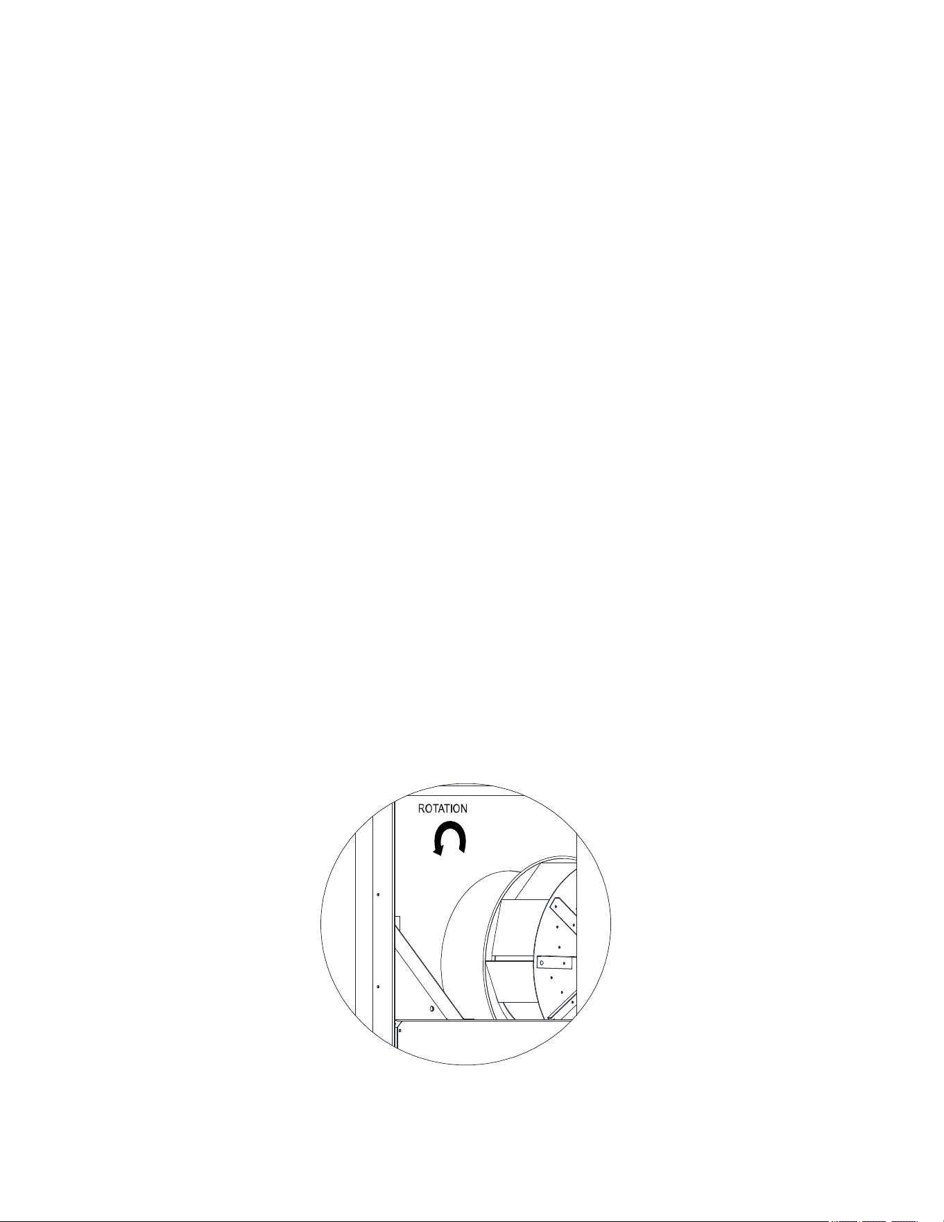
82
UNIT OPERATION
WARNING: Gloves and safety glasses must be worn when servicing refrigeration
equipment.
Before starting or operating the unit, verify all fasteners are secure and tight. In particular, check the set
screw in the wheel hub. Verify power and gas are OFF to the unit. Before connecting the unit to power, turn
the fan wheel by hand to verify it is not striking the inlet, or there are any obstructions. Re-center, if
necessary.
Special Tools Required for start-up: AC Voltage Meter, Standard Hand Tools, Differential Pressure Gauge,
Thermometer, Tachometer, Amperage Meter, Refrigeration Gauge Set
Start-Up Procedure
1. Check all electrical connections are secure and tight.
2. Inspect the condition of the intake damper and damper linkage, if applicable.
3. Inspect the air-stream for obstructions. Install necessary filters.
4. Verify all drains are connected and routed in the proper positions. For high-efficiency furnaces, verify
the condensate drain is connected. Refer to “Furnace Condensation Drain” on page 17.
5. Compare the supplied motor voltage with the fan’s nameplate voltage. If this does not match, correct
the problem.
6. Check the rotation of the wheel motor. Verify the wheel is moving in the direction of the directional
arrow (Figure 38). Incorrect rotation will result in poor air performance, motor overloading, and
possible damage to the motor. If the motor rotation is incorrect, adjust using the HMI panel. Go to:
Factory Settings > Unit Options > Blower Config > Supply VFD Direction > Forward.
7. When the fan is started, observe the operation and check for any unusual noises.
8. Connect a refrigerant gauge set to the system. Refer to “Monitoring the A/C System” on page 109.
Verify the high side and low side pressure readings are equal at the initial connection.
9. Monitor the surface temperature with a thermometer.
10. Start and run the unit for approximately 20 minutes.
11. Monitor the manifold gauge, surface temperature, subcool, and superheat readings:
- Refer to Table 16 on page 124 to convert the pressure gauge readings to temperature.
- The subcool reading should be approximately 10-20°F.
- The superheat reading should be approximately 20°F.
Figure 38 - Direction of Rotation

83
Start-Up Procedure Heating
Furnace Start-Up Summary
1. Open the field-installed manual gas shut-off valve and ensure the On/Off gas control valve knob is set
to ‘On.’
2. Check inlets to all firing tubes on the furnace and ensure that they are all clear of foreign debris. Verify
that the tubes line up properly with each nozzle of the gas manifold.
3. Start the unit and check the gas supply pressure at the inlet gas gauge, this gauge is upstream of all
electronic gas valves. The inlet pressure should be 7 in. - 14 in. wc on natural gas or 11 in. – 14 in.
wc on propane gas. If the inlet pressure is too high, install an additional pressure regulator external to
the unit.
4. Verify DIP switches are set correctly on the modulating valve (Figure 39). Factory setting for DIP
switches is Off. Refer to Table 14 for DIP switch settings.
5. A final gas leak check shall be performed to verify the gas-tightness of the heater’s components and
piping under normal operating conditions.
6. At any point during high/low fire burner adjustment, check the characteristics of the flames in every
firing tube of the furnace. Non-existence of flame or a lazy flame can be caused by no gas pressure,
low gas pressure, a dirty nozzle orifice, or clogged section of exhaust flue.
7. When testing has completed, replace all caps and covers removed during the adjustment procedure.
High Fire Burner Adjustment
1. Set the unit into high fire mode. This is achieved by configuring high fire by going into the HMI’s
configuration, refer to “HMI Configuration Menu Access” on page 56. Go to: Service > Test Menu
> Test Gas Heat > Run High Fire Test.
2. After it has been verified that the furnace(s) are lighting off properly, the manifold gas pressure should
be adjusted to jobsite conditions. The gas pressure regulator (integral to the On/Off gas control valve,
refer to Figure 16) is adjusted at the factory for average gas conditions. The gas supplied to the
furnace must be in accordance with the input rating on the rating plate. Once the gas pressure is
verified, continue to step 3.
3. If the unit is set up for analog control, continue with high fire using the method above or send the unit a
constant 10V DC or 20mA signal. Refer to Table 14.
- Remove the cover on the modulating valve (Figure 39). Read the manifold gas pressure gauge
(0-10 in. wc) located directly on the gas manifold. The pressure should read 3.5 in. wc for natural
gas / 10 in. wc for propane. If the pressure is incorrect, adjust the pressure.
- To adjust the pressure, press button #1 until the LED lights solid red. Release the button. The valve
is now in high fire setting mode.
- Buttons #1 and #2 are used to set high fire setting. Press once to step or hold to auto step.
4. If the proper (in. wc) gas pressure cannot be achieved by adjusting the modulating gas valve, and it
has been verified that the inlet gas pressure is within the acceptable range of 7 - 14 in. wc on natural
gas and 11 – 14 in. wc on propane gas, adjust the regulator on the On/Off gas control valve. Use a
screwdriver to turn the inner adjustment screw clockwise to increase the gas pressure, Figure
16.
Table 14 - Modulating Valve Dip Switch Settings
Control Signal SW1 Signal SW2 Offset SW3 Characteristic
0-10 V OFF OFF OFF
2-10 V OFF ON OFF
0-2 mA ON OFF OFF
4-20 mA ON ON OFF
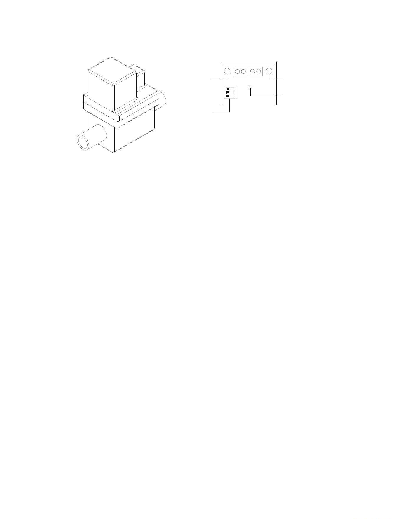
84
Figure 39 - Modulating Valve and Controls
Low-Fire Burner Adjustment
1. Lock the unit into low fire mode. This is achieved by configuring low fire by going into the HMI’s
configuration, go to: Service > Test Menu > Test Gas Heat > Run Low Fire Test.
2. Press and hold button #2 on the modulating valve until the LED light blinks red. Release the button.
The valve is now in low fire setting mode.
3. Press button #1 to increase flow or press button #2 to decrease flow.
- The desired pressure reading for natural gas is 0.15 in. wc If this cannot be obtained, set the low fire
pressure as low as possible.
- The pressure reading for propane gas should be 0.75 in. wc
4. Save the low fire setting by simultaneously holding down buttons #1 and #2 until the blinking LED turns
off. Press the abort button on the HMI to exit low fire mode.
Final Start-Up Procedure
1. With the air and burner systems in full operation and all ductwork attached, measure the system
airflow.
2. Once the proper airflow is achieved, measure and record the fan speed with a reliable tachometer.
Caution - Excessive speed will result in motor overloading or bearing failure. Do not set fan
RPMs higher than specified in the maximum RPM chart.
3. Measure and record the voltage and amperage to the motor and compare with the motor nameplate
to determine if the motor is operating under safe load condition.
4. Check for any obstructions, tools, or hardware that may cause damage when unit is in full operation.
5. Make sure all access panels are in place and secure.
BUTTON 1
BUTTON 2
DIP SWITCHES
LED DISPLAY

85
Sequence of Operation
Operation Summary - Gas Heating
• When there is a call for heat, the main blower is turned “On” and the airflow switch is proven.
• The Flame Safety Controller (FSC-1) sends 120V AC power to the line input of the power vent blower.
• Power vent blower is controlled by pin J17 on the control board. This varies a signal to the power vent
blower motor to initiate a 1 min pre-purge at high speed.
• 24V AC signal runs through the safety circuit (Power Vent Airflow Switch/High Temperature Limit/
Flame Roll-out Switch) and into FSC-1.
• FSC-1 initiates Trial for Ignition by sending a signal to the spark igniter to light the furnace and 24V AC
power to the On/Off gas valve and a signal to the HMI that it is sparking. This opens the On/Off gas
valve and triggers the start of the 17-seconds from the HMI to the powervent blower, and modulating
valve.
• Flame is sensed by FSC-1’s remote flame sensor at the firing tube of furnace.
• HMI’s 17-second high-fire off-delay time sequence runs out, and a variable voltage is sent to the
power vent blower motor.
• The control board continues to modulate the heat output of the unit by adjusting the 0-10V DC signal to
the modulating gas valve.
NOTE: If a high turndown furnace is present, this sequence occurs with FSC-2 if the call for heat
dictates a need for a second furnace.
There are different options for controlling the temperature output of these units. These include Discharge
Temperature Control, Space Temperature Control, Analog Control, and Direct Digital Control (DDC).
Discharge Control:
When used in discharge control, the MUA board receives a call to heat from the
intake sensor, the MUA board will modulate the discharge temperature until it hits the desired set point.
The user can choose whether discharge heating is activated based on intake temperature, space
temperature, either, both, or stat.
Space Control:
When the space control option has been selected, there may be an HMI (that contains an
internal temperature sensor) or a space thermistor. The user can choose whether the space heating is
activated based on intake temperature, space temperature, either, both or stat.
Analog Control/Direct Digital Control (DDC)
: A 0-10V DC or 0-20mA signal is sent to the MUA board
from the building control system to regulate the heating output of the unit.
In all cases, the MUA board controls the amount of gas to the burner based on the signal from the
temperature control components. When the modulating gas valve is all the way open, achieving the
maximum BTUs and temperature rise of the unit, the unit is in high fire.

86
Flame Safety Control (FSC)
The Flame Safety Control (FSC) is present only to monitor the flame, NOT to control temperature.
The FSC uses a sensor mounted at the intake of the upper-most firing tube of the furnace to sense the
existence of a flame. The FSC controls the opening of the solenoid gas valve, and the operation of the
spark igniter to initiate a flame upon start-up. When there is a call for heat, the LED on the FSC is
energized, indicating that the unit has power. Then, there is a one-minute pre-purge. The power vent
blower on the furnace is sent to high speed to exhaust any gas in the Heat-exchanger/Control Cabinet that
may be present before trial for ignition. As soon as the pre-purge has initiated, the FSC checks that airflow
is sensed by the power vent airflow switch and that the High Limit and Roll-out switches are not tripped.
Upon successful sensing of induced power vent airflow, continuity of temperature limit, and roll-out
switches, the FSC initiates a 15-second ignition sequence. During this ignition sequence (Figure 40), the
FSC opens the On/Off gas valve and allows gas to pass through to the gas manifold. At the same moment,
the spark igniter begins to spark, causing the electrode on the burner to ignite the gas. This results in a
flame at the lowest firing tube of the furnace. This immediately ignites the flow of gas in each succeeding
firing tube moving vertically until the entire furnace is lit. When the sensor detects the flame at the intake of
the uppermost firing tube, the FSC continues to power the On/Off gas valve until there is a loss of flame
presence. This is the normal operating mode.
Figure 40 - Ignition Sequence
Modulating Stage Sequence
The modulating stage operates differently than other On/Off staged furnaces. Instead of being “On” or
“Off,” the gas flow to this furnace is modulated up and down to account for varying calls for heat during the
unit’s operating period. In addition, the speed of its power vent blower is varied as the gas flow changes to
maintain constant combustion efficiency over the entire firing range.
The modulating furnace power vent blower is controlled by an on-board speed controller, located on the
MUA control board. Voltage to the motor is based on a 0-10V DC signal. The output voltage (True RMS) to
the motor varies non-linearly between 120V AC @ 10V DC for high fire and 86.5V AC @ 0V DC for low
fire.
MUA Board and High Fire Start
The MUA board compares a difference between two sensor values and set points; or compares a 0-10V
DC or 0-20 mA signal from an analog control to the modulating furnace. The signal is linearized such that
input voltage is directly proportional to amount of gas being delivered to the modulating valve.
To ensure proper light-off in all conditions, the MUA board contains software that forces the modulating
furnace to light at high-fire when that furnace’s main gas valve is first opened. There is a built-in timer that
allows it to send a constant 10V DC signal to the modulating gas valve, and power vent blower speed
controller. This will force the furnace into high-fire for a period of 17-seconds after the initial spark is sent
by the FSC. After this forced high-fire light-off period has expired, the modulating furnace’s power vent
blower and modulating gas valve will receive a modulating signal from the MUA board.
Interval
Description
Time (Min:Sec)
(Non-Linear Scale)
Initial Call
for Heat
1 Min.
Pre-Purge
15 Sec. Trial
for Ignition
1 Min.
Inter-Purge
15 Sec. Trial
for Ignition
1 Min.
Inter-Purge
15 Sec. Trial
for Ignition
2 Min.
Post-Purge
1 Hr
Lockout
Repeat
Cycle
0:00 1:00 1:15 2:15 2:30 3:30 3:45 5:45 End Cycle

87
Re-Circulating Control Options
The ratio of outdoor to indoor air in the discharge supply air can be adjusted through the MUA board
output. The board will output a 0-10V DC signal to command the position of the damper. There are several
options for controlling the position of this damper. Use the HMI panel to change options:
Factory Settings > Unit Options > Outdoor Air Config> Outdoor Air Ctrl
Powered Exhaust
The powered exhaust fan is located by the intake damper assembly and is designed to prevent the
building from over pressurizing. When there is excessive static in the building’s return ductwork, the
powered exhaust fan will assist exhausting air directly outdoors to balance the building’s internal pressure.
The powered exhaust fan will actuate depending on the outdoor air configuration’s settings and supply fan
activation.
Outdoor Air Configuration
When Outdoor Air % or Schedule is selected, “Outdoor Air Deadband” will be active. This setting checks
the delta T between outdoor and return air. If the difference between these two temperatures is less than
or equal to the dead band setting (default setting is 5 degrees), the MUA board will not alter its output to
the damper assembly.
Off - Outdoor air control from the control board will not output a signal. May be used when damper is
controlled by a photohelic gauge or a Building Management System (BMS).
Manual - The fresh air dampers can be manually controlled from the HMI panel corresponding to a 0-10V
DC output signal from the control board. This output voltage signal can be manually adjusted. This will
allow the user to manually set the dampers to match the building ventilation requirements.
2 Position - The fresh air dampers can be controlled by a two-position switch (a field-supplied switching
device) to select closed position or 100% open. The control board sends out a constant 10V DC signal to
the actuator. The field supplied switch will break or make the signal from the control board to the outdoor
air damper. When the switch is used to disconnect power (open the circuit), or if a power failure occurs, or
if the control board is shut-off, the return air damper will open by spring return. If using a two-position
switch, connect in series to the control board at connection A+ and D+.
Outdoor Air % - The dampers can be controlled from the HMI to position the dampers from 0% to 100%
fresh air. The MUA board utilizes an internal algorithm to alter its 0-10V output to the damper assembly to
maintain an exact outdoor air percentage.
100% OA - If this damper control is chosen, anytime the blower is running, the damper will be fully open.
The board logic will send 10 volts to open the damper. When there is no call for the blower, the board logic
will send 0 volts to close the damper.
Analog Control - When this is set to ON, the damper will modulate linearly between the min and max OA
voltage for both occupied and unoccupied modes.
Pressure Control - Damper position will modulate to maintain building pressure. Building pressure below
the set point will increase the amount of outdoor air supplied to increase pressure.
NOTE: When Scheduling is enabled, separate occupied and unoccupied set points will be available
for outdoor air control settings.
Programmable Thermostat
The programmable thermostat can be set off the discharge sensor set point. This allows the unit to
modulate for the programmed space set point. An example would be, if the discharge set point is set for
65°F, and the space calls for heat/cooling cycle, the unit will modulate to meet the discharge set point.
The thermostat can also work off blower mode. This setting will look at the intake air temperature. The unit
will modulate to avoid bringing in too hot or too cold of air into the space.
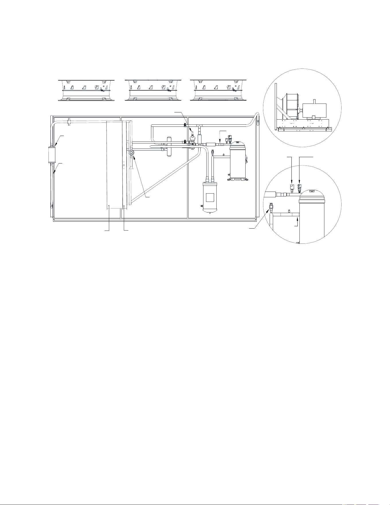
88
Heating, Cooling, Defrost, and Reheat
Figure 41 - Heat Pump with Reheat Option
NOTE: Figure 41 is one example of many configurations offered.
Air velocity should be maintained between 200 and 550 fpm through the indoor coil.
Heating cycle (heat pump)
• In heating mode, the outdoor coil acts as the evaporator coil. When the thermostat calls for a heating
sequence, the reversing valve is automatically powered. The compressor and outdoor fan start. The
heating system is now in operation. Once the thermostat is satisfied, the system will shut down.
• The compressor pumps out high pressure refrigerant vapor. The vapor leaves the compressor, and
then through the energized reversing valve.
• The refrigerant then flows through the indoor coil. Supply air removes heat from the refrigerant vapor,
warming the indoor air and heating the building. When enough heat is removed, the vapor condenses
into a high pressure liquid. The liquid temperature is slightly warmer than indoor air temperature. The
liquid refrigerant then passes through an Electronic Expansion Valve (EEV), reducing its pressure and
temperature, then passes through a filter/drier. The filter/drier adsorbs water and filters system
contaminants.
• As the cool, low pressure liquid refrigerant enters the outdoor coil, it expands and absorbs heat from
the outdoor air passing over the finned surface. Heat from the outdoor air causes the low pressure
liquid to evaporate into a cool vapor.
• The cold refrigerant vapor passes through the outdoor vapor line to the reversing valve. The reversing
valve directs refrigerant into the accumulator. The accumulator holds a liquid refrigerant and oil
mixture, and controls flow back to the compressor. The liquid refrigerant and oil mixture are metered
back to the compressor through a small orifice near the bottom of the accumulator.
• The refrigerant vapor passes through the suction line to the intake of the compressor. The cycle then
repeats.
Outdoor Fan(s)
Filter/Drier
Outdoor Coil
Indoor Coil
Reheat Coil
Electronic
Expansion Valve
Reversing
Valve
Accumulator
Compressor
Supply Fan
Suction
Line
Discharge Line
High
Refrigeration
Pressure
Switch
Hot Gas Reheat Valve (HG-1)
Low Refrigeration
Pressure Switch
Discharge
Pressure
Sensor
Liquid Line Pressure
Sensor
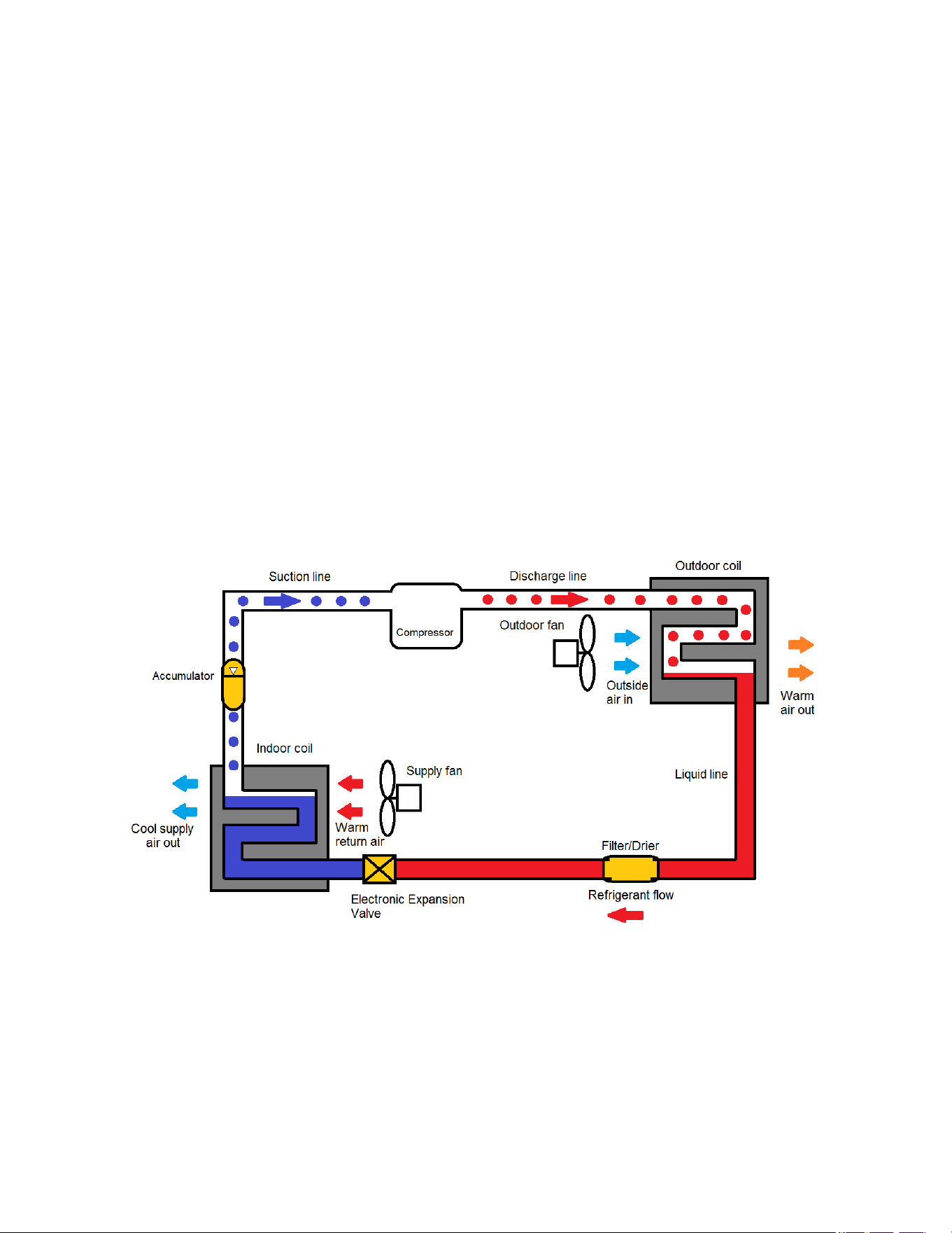
89
Cooling cycle
Figure 42 is a basic representation of the cooling cycle.
• When the cooling sequence is initiated, the compressor and outdoor fan start. The cooling system is
now in operation. Once the thermostat is satisfied, the system will shut down.
• The compressor pumps out high pressure refrigerant vapor (discharge line). The vapor leaves the
compressor. If the unit is a heat pump, the vapor will pass through the de-energized reversing valve.
• The vapor flows through the discharge line to the outdoor coil. Air from the outdoor fan removes heat
from the refrigerant vapor. When enough heat is removed, the vapor condenses into a high pressure
liquid. The liquid temperature is slightly warmer than ambient air temperature. This warm, high
pressure liquid leaves the outdoor coil and flows through the copper refrigerant line. The liquid passes
through a filter/drier. The filter/drier adsorbs water and filters system contaminants.
• At the end of the line, the refrigerant passes through an Electronic Expansion Valve (EEV), reducing its
pressure and temperature.
• As the liquid, under reduced pressure, enters the indoor coil, it expands and absorbs heat from the
indoor air passing over the finned surface. Heat from the indoor air, causes the low pressure liquid to
evaporate, and cools the indoor air. The refrigerant is now a cool vapor.
• Refrigerant vapor passes through the insulated vapor line. If the unit is a heat pump, a reversing valve
will direct refrigerant into the accumulator. The accumulator controls liquid refrigerant and refrigerant
oil flow back to the compressor. Refrigerant vapor passes through the suction line to the compressor.
The cycle then repeats.
Figure 42 - Cooling Cycle
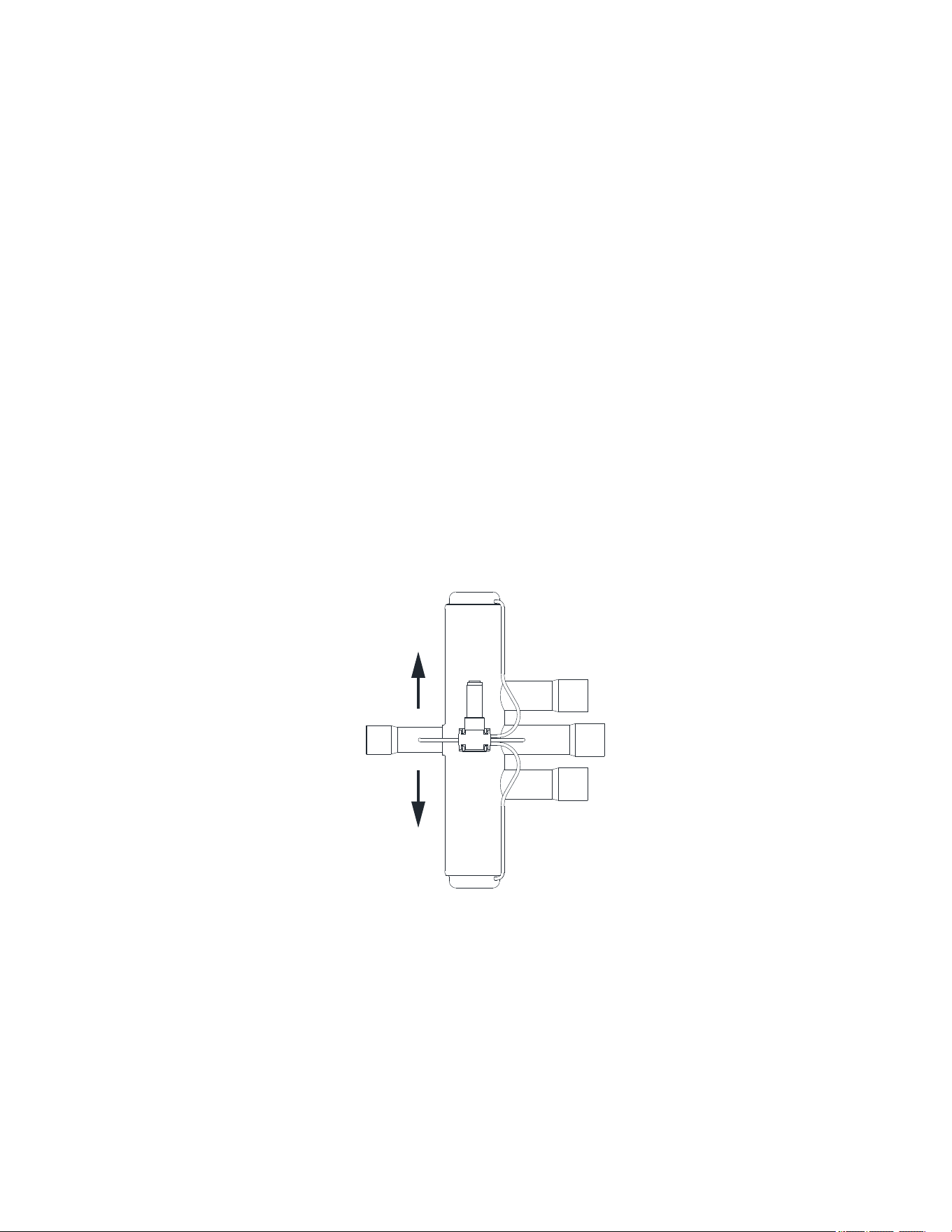
90
Defrost cycle (heat pump)
• In heating mode, the outdoor (condensing) coil acts as the evaporator coil. Moisture from the outside
air condenses on the outside coil, and normally runs off. During the colder part of the heating season,
this moisture freezes. This frozen moisture blocks air movement through the coil. A defrost cycle
needs to be run to remove the frost.
• The defrost control detects the buildup of ice on the outdoor coil. The reversing valve will direct hot gas
from the compressor to the outdoor coil. This starts the defrost process.
• The outdoor fan stops to prevent cold air from being passed onto the outdoor coil while hot refrigerant
is in the outdoor coil.
• When the defrost control has detected the ice has melted, the defrost mode will end. The reversing
valve shifts to the heating position. Hot refrigerant gas is then sent to the indoor coil. The outdoor fan
operates, and the unit is now in normal heating mode.
Reheat cycle (cooling only)
• During the reheat cycle, a portion of the hot gas from the compressor enters the reheat coil and then is
fed into the discharge line to the outdoor coil.
• The air is cooled and dehumidified as it flows across the indoor coil. It is then reheated by the reheat
coil to lower the relative humidity.
Reversing valve for heating/cooling (heat pump)
When the unit is set up to run as a heat pump, the reversing valve is activated before the compressor
starts. The reversing valve will de-energize if there is a call for cooling. Refer to Figure 43 for details.
• When the internal valve is de-energized (down), the unit will be in cooling mode.
• When the internal valve is energized (up), the unit will be in heating mode.
Figure 43 - Reversing Valve
Discharge
Connection
Outdoor Coil
Connection
Suction
Connection
Indoor Coil
Connection
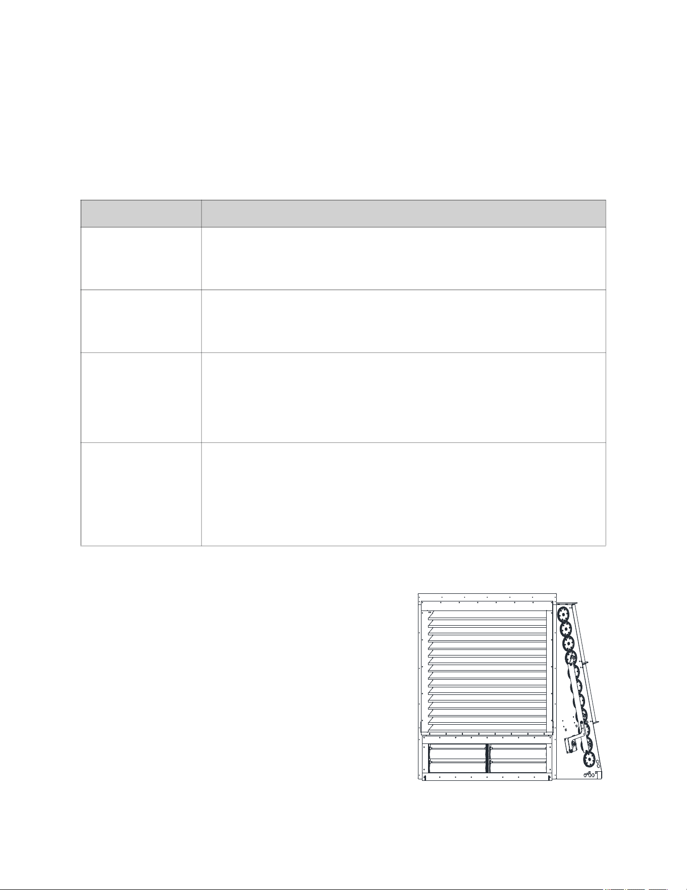
91
Economizer
Economizer type sets the type of economizer logic that will be used. This feature will control the
economizer using a 0-10V DC signal output on the MUA board. The table below shows option selections
and definitions.
Use the HMI to select Economizer type. Go to Factory Settings > Unit Options > Outdoor Air Config >
Economizer.
Disable Cooling
Figure 44 - Damper Assembly
This allows the user to set the Outdoor Air (OA) percentage
through the damper assembly (Figure 44) when mechanical
cooling is disabled.
Refer to “Psychrometric Chart” on page 92 for economizer
operation and logic.
Table 15 - Economizer Options
Option Definition
Fixed Dry Bulb The economizer will modulate open if the outdoor air temperature is less than
the economizer temperature set point. The modulation occurs from the current
damper position to fully open over a specific temperature range (determined by
the economizer temperature band value).
Differential Dry Bulb The economizer will modulate open if the outdoor air temperature is less than
the return air temperature. The modulation occurs from the current damper
position to fully open over a specific temperature range (determined by the
economizer temperature band value).
Fixed Total The economizer will modulate open from the current position if the outdoor air
dew point temperature is less than the economizer dew point set point, and the
outdoor dry bulb temperature is less than the economizer temperature set
point. The dew point set point is calculated using the economizer temperature
and humidity set points. The modulation occurs from the current damper
position to fully open over a specific dew point temperature band.
Differential Total The economizer will modulate open from the current position if the outdoor air
wet bulb temperature is less than the economizer dew point set point, and the
outdoor dry bulb temperature is less than the economizer temperature set
point. If the return dew point is less than the dew point set point, the unit will
use the return dew point as the beginning of the modulation band. The
modulation occurs from the current damper position to fully open over a specific
dew point temperature band.
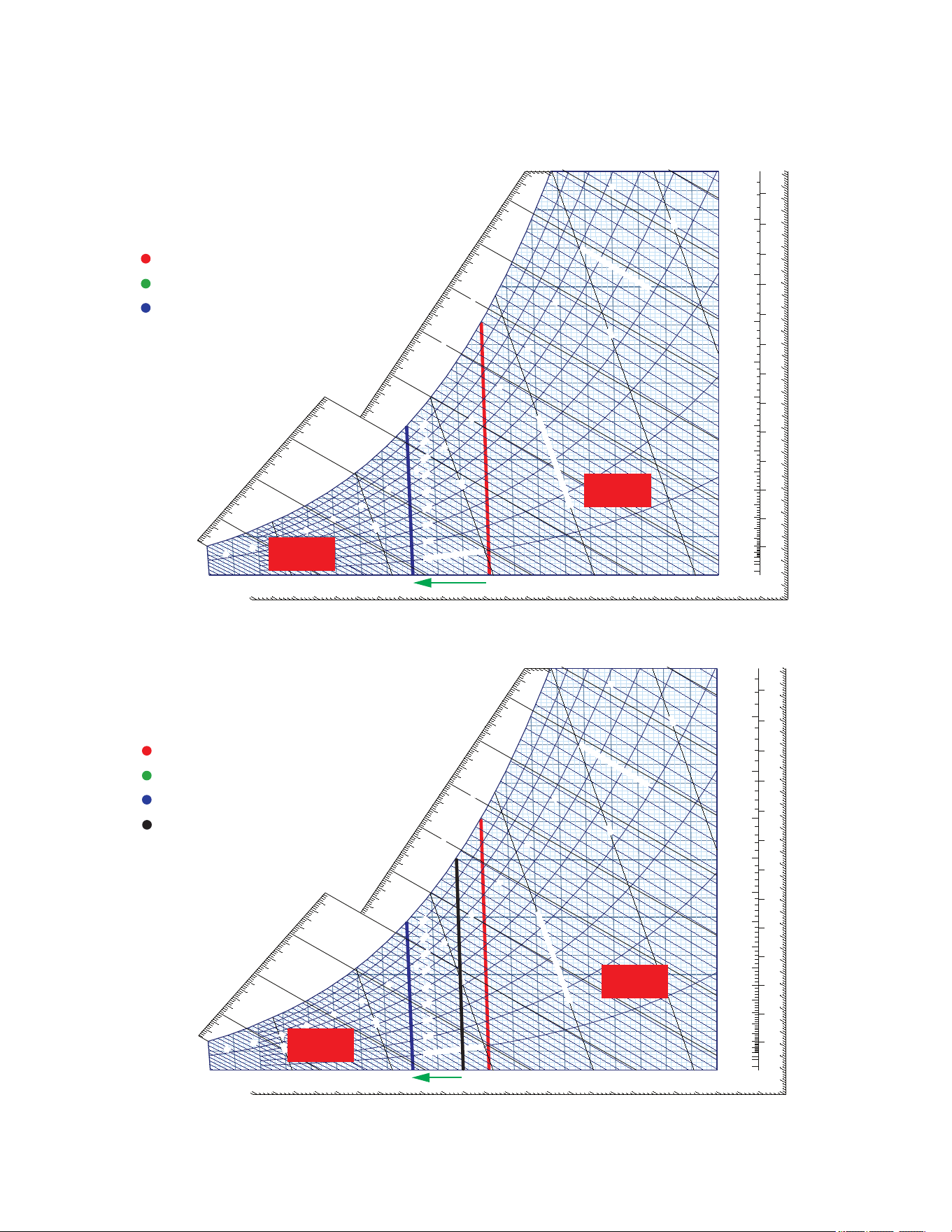
92
Psychrometric Chart
Fixed Dry Bulb Economizer
Differential Dry Bulb Economizer
45 50 55 6020 25 30 35 40 65 85 90 95 100 105 110 115 12070 75 80
DRY BULB TEMPERATURE - °F
10
20
30
40
50
60
70
80
90
100
110
120
130
140
150
160
170
180
190
200
210
10
15
20
25
30
35
40
45
50
55
55
60
60
65
ENTHALPY - BTU PER POUND OF DRY AIR
10
15
20
25
30
35
40
45
50
AT
ENTHALPY - BTU PER POUND OF DRY AIR
SATUR ION TEMPERATURE - °F
20
25
25
30
30
35
35
40
40
45
45
50
50
55
55
60
60
65
65
70
70
75
75
80
80
85 WET BULB TEMPERATURE - °F
85
90
10% RELATIVE HUMIDITY
20%
30%
40%
50%
60%
70%
80%
90%
12.5
13.0
13.5
SPEC14.0 IFIC VOLUME ft³/lb OF D IRY A R
14.5
15.0
HUMIDITY RATIO - GRAINS OF MOISTURE PER POUND OF DRY AIR
.1
.2
.3
.4
.5
.6
.7
.8
.9
1
1.1
1.2
1.3
VAPOR PRESSURE - INCHES OF MERCURY
-20
0
10
20
25
30
35
40
45
50
55
60
65
70
75
80
85
DEW POINT - °F
Psychrometric Chart
Normal Temperature
I-P Units
Sea Level
Barometric Pressure: 29.921 Inches of HG
Set Point Temp
Economizer Band
Low Limit Temp
0%50%100%
Outdoor Air
ENTHALPY - BTU PER POUND OF DRY AIR
MAX OA
MIN OA
45 50 55 6020 25 30 35 40 65 85 90 95 100 105 110 115 12070 75 80
DRY BULB TEMPERATURE - °F
10
20
30
40
50
60
70
80
90
100
110
120
130
140
150
160
170
180
190
200
210
10
15
20
25
30
35
40
45
50
55
55
60
60
65
ENTHALPY - BTU PER POUND OF DRY AIR
10
15
20
25
30
35
40
45
50
AT
ENTHALPY - BTU PER POUND OF DRY AIR
SATUR ION TEMPERATURE - °F
20
25
25
30
30
35
35
40
40
45
45
50
50
55
55
60
60
65
65
70
70
75
75
80
80
85 WET BULB TEMPERATURE - °F
85
90
10% RELATIVE HUMIDITY
20%
30%
40%
50%
60%
70%
80%
90%
12.5
13.0
13.5
SPEC14.0 IFIC VOLUME ft³/lb OF D IRY A R
14.5
15.0
.1
.2
.3
.4
.5
.6
.7
.8
.9
1
1.1
1.2
1.3
VAPOR PRESSURE - INCHES OF MERCURY
-20
0
10
20
25
30
35
40
45
50
55
60
65
70
75
80
85
DEW POINT - °F
Psychrometric Chart
Normal Temperature
I-P Units
Sea Level
Barometric Pressure: 29.921 Inches of HG
Set Point Temp
Economizer Band
Low Limit Temp
0%
50%100%
Outdoor Air
ENTHALPY - BTU PER POUND OF DRY AIR
MAX OA
MIN OA
Return Temp
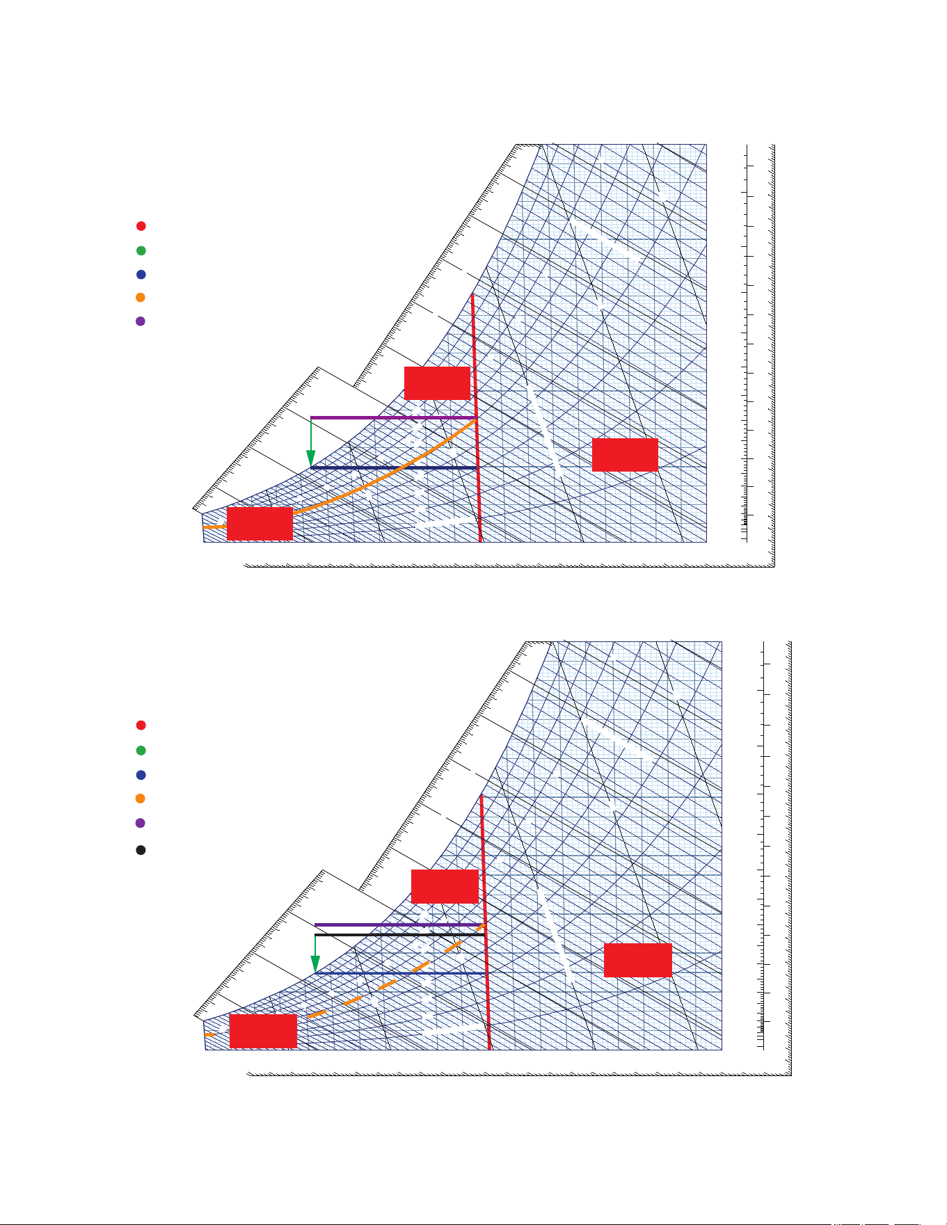
93
Fixed Total Economizer
Differential Total Economizer
45 50 55 6020 25 30 35 40 65 85 90 95 100 105 110 115 12070 75 80
DRY BULB TEMPERATURE - °F
10
20
30
40
50
60
70
80
90
100
110
120
130
140
150
160
170
180
190
200
210
10
15
20
25
30
35
40
45
50
55
55
60
60
65
ENTHALPY - BTU PER POUND OF DRY AIR
10
15
20
25
30
35
40
45
50
AT
ENTHALPY - BTU PER POUND OF DRY AIR
SATUR ION TEMPERATURE - °F
20
25
25
30
30
35
35
40
40
45
45
50
50
55
55
60
60
65
65
70
70
75
75
80
80
85 WET BULB TEMPERATURE - °F
85
90
10% RELATIVE HUMIDITY
20%
30%
40%
50%
60%
70%
80%
90%
12.5
13.0
13.5
SPEC14.0 IFIC VOLUME ft³/lb OF D IRY A R
14.5
15.0
.1
.2
.3
.4
.5
.6
.7
.8
.9
1
1.1
1.2
1.3
VAPOR PRESSURE - INCHES OF MERCURY
-20
0
10
20
25
30
35
40
45
50
55
60
65
70
75
80
85
DEW POINT - °F
Psychrometric Chart
Normal Temperature
I-P Units
Sea Level
Barometric Pressure: 29.921 Inches of HG
Set Point Temp
Economizer Band
Low Limit DP
0%
50%
100%
Outdoor Air
ENTHALPY - BTU PER POUND OF DRY AIR
MIN OA
Set Point %RH
High Limit DP
MAX OA
MIN OA
Return DP
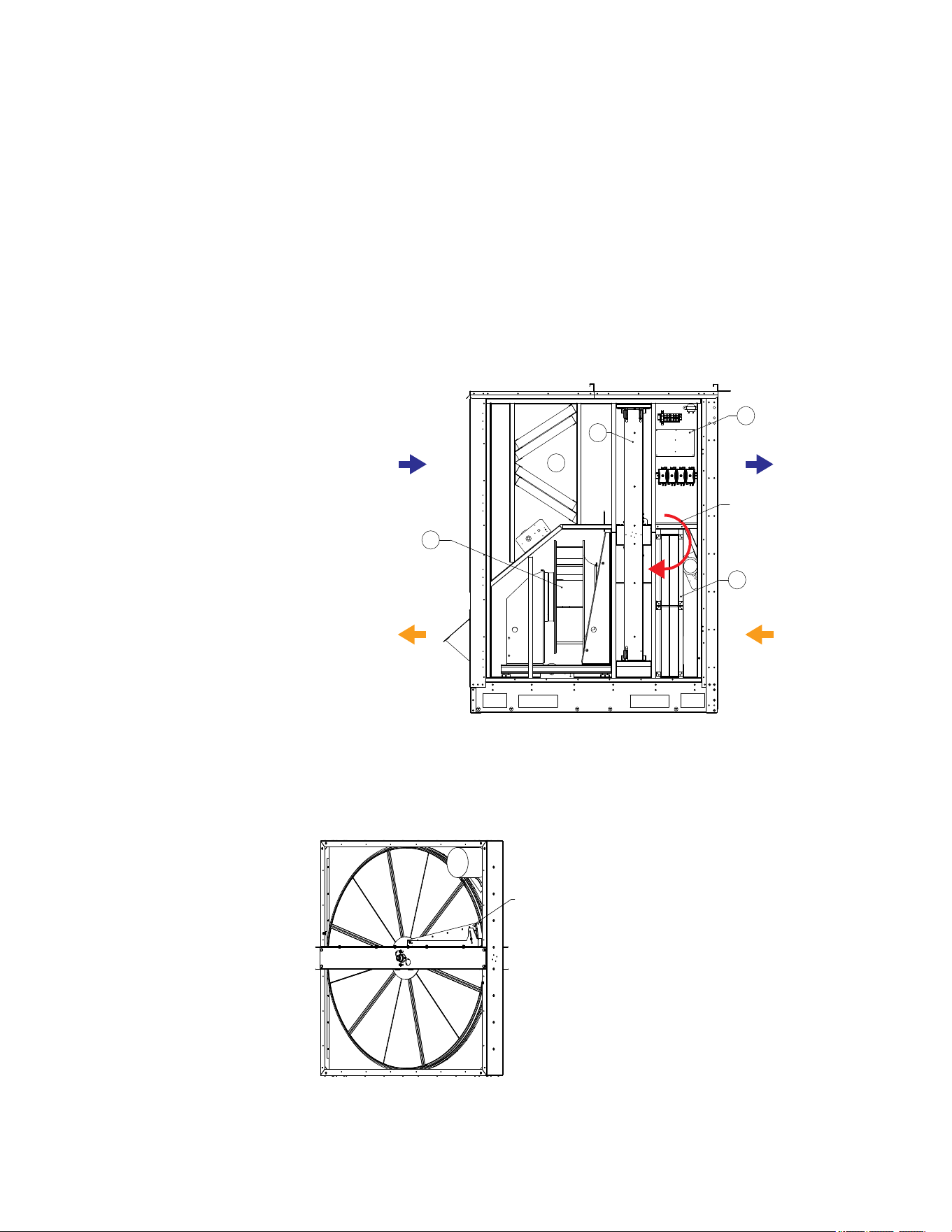
94
Energy Recovery (Optional)
The Energy Recovery (Enthalpy) Wheel is assembled and installed from the factory. Minimal maintenance
will provide years of trouble-free service.
If the unit is equipped with the optional enthalpy wheel, energy recovery is provided by pulling outside air
across half of the wheel and moving exhaust air across the other half. Latent heat and sensible heat are
moved from the hotter and moist exhaust air to the colder and dry outside air during winter conditions.
Latent heat and sensible heat are transferred from the hotter and moist outside air to the cooler and dry
exhaust air during summer conditions. Enthalpy control comprises of starting and stopping the exhaust
fan, modulating the speed of the exhaust fan, starting and stopping the enthalpy wheel, and optionally
controlling the speed of the enthalpy wheel. If required by outdoor air conditions, the outdoor damper is
controlled in the normal manner. Figure 45 provides details for components associated with the enthalpy
wheel.
Figure 45 - Energy Recovery Wheel Overview
Purge and Pressurization
Pressurization is critical to minimize crossover from exhaust to supply and to allow the purge to operate
properly. Move the adjustable purge plate (Figure 46) up to increase purge and minimize crossover.
Figure 46 - Purge Details
1. Outdoor Air Filtration
2. Energy Wheel
3. ERV Controls
4. Return/Exhaust Filtration
5. ECM Exhaust Fan
Outdoor Air
Supply Air
Return Air
Exhaust Air
Purge
1
3
4
2
5
Adjustable purge plate.

95
Drive Motor
The enthalpy wheel comes standard with a variable speed drive motor, which is pre-wired to turn in the
proper direction. The motor can adjust speed to lower the enthalpy’s wheel capacity during frosting
conditions. This lowered capacity allows the wheel to recover energy still while preventing frosting. During
non-frosting conditions, the modulation of the wheel allows enhanced capacity control of wheel for greater
turn-down and more precise discharge control.
Frost Protection (Optional)
Figure 47 illustrates frost prevention conditions. During extremely cold winter conditions, the wheel can
frost overdue to the moisture content of the return/exhaust air. A frozen wheel will increase static pressure
and reduce efficiency of the wheel. If the wheel fully freezes, the host unit can be starved of supply air. To
avoid this situation, the recovery wheel comes standard with a variable speed motor that modulates down
during frosting conditions.
Figure 47 - Frost Prevention Psychrometric Chart
Variable Speed Frost Prevention
When there is a threat of frost on the enthalpy wheel, the wheel is slowed down so that less enthalpy
transfer occurs, and frosting of the wheel is avoided. Frosting can occur on the enthalpy wheel when the
exhaust air leaving the wheel is saturated. This condition occurs when the energy transfer and saturated
air lines intersect on a psychrometric chart, and it does not occur when these two lines do not intersect.
Energy Recovery Exhaust Hoods
Units with the optional energy recovery module have an exhaust hood. Each hood is factory installed over
the barometric relief, allowing the unit to function in adverse weather without the risk of water/debris
infiltration.
Exhaust Fan
Unit utilizes an integral ECM exhaust fan that features various control modes to optimize energy transfer
and ensure proper air movement. Exhaust cabinet features barometric relief that seals when the exhaust
fan is not powered. This will allow for return air to be utilized when the ERV is off.
Slide-Out Wheel
The wheel can be pulled out to facilitate cleaning and servicing. Power wires for the wheel will need to be
unfastened from the lid of the module to allow the full range of motion necessary to service the wheel.
Dry Bulb
Humidity
Ratio
Saturated
Air
Saturated
Air
Saturated
Temperature
Frost
Conditions
No Frost
Conditions
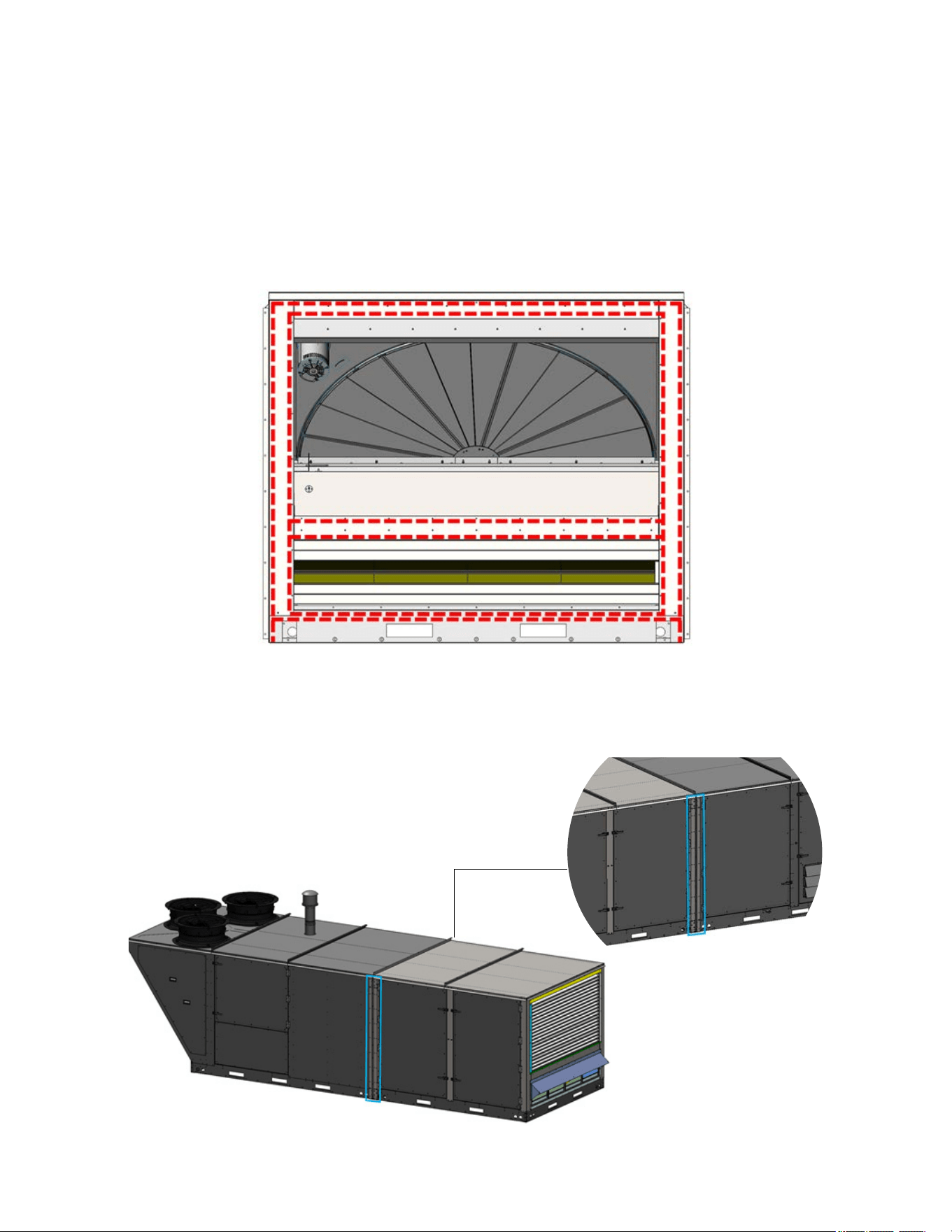
96
Field Installation of Large ERVs
Due to their larger size, some ERVs are shipped loose and must be mounted and wired in the field. This section
and Figure 48 through Figure 51 on page 97 cover the install and wiring process for large ERVs. These larger
ERVs will have hardware bags and gasket rolls placed inside before shipping. Such units should have the gasket
applied to the mating side as shown in Figure 48.
If the unit is not gasketed already, add gasketing to the marked lines on the mounting side of the ERV before
installation (Figure 48). Ensure that any joints between gasket strips are silicone to guarantee water cannot travel
between the strips.
Figure 48 - ERV Gasket Outline
Next, align the ERV with the DOAS unit. Ensure that the marked brackets (Figure 49) are aligned and pushed as
close together as possible.
Figure 49 - ERV Mating Profile
Control Side Brackets
Blower Side Brackets
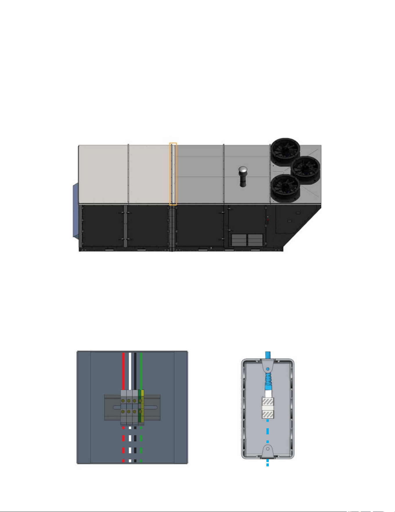
97
After the units are positioned correctly, push the bolts through the aligned holes on the side mounting brackets and
hand tighten the nuts on the other side. BOTH SIDES MUST HAVE THE BOLTS INTALLED AND HAND
TIGHTENED.
Working around the unit (from side to side), uniformly tighten the bolts to bring the modules together. Ensure the
gasket between the two mating surfaces are compressed. FAILURE TO DO SO CAN RESULT IN POOR
SEALING AND WARPED METAL ON THE UNIT.
Once the ERV has been mounted tight against the DOAS, place the top mating bracket over the exposed raised
flange on the ERV lid (Figure 50). Liberally apply silicone to all points of contact between the mating bracket and
lids. Rivet the mating bracket to the raised flange of the ERV lid. Use 1-1/2” (max) rubber-washer self-tapping
screws to attach to the lid of the DOAS.
Figure 50 - ERV Top Lid
With the ERV fully attached, the power and communication wires must be connected (Figure 51). MAKE SURE
THE UNIT HAS NO POWER TO ITS MAIN DISCONNECT BEFORE CONTINUING.
The ERV will have junction boxes in the lower right of the module relative to the control panel. The largest junction
box will have a set of terminal blocks for incoming power. Two cable bundles that require field wiring will be
spooled and stored in the return opening of the DOAS. The larger junction box will have terminal blocks for
incoming power for the ERV module. The smaller junction box will have a CAT5 cable with a coupler. Connect the
supplied CAT5 cable from the DOAS to the coupler. With this done, restore power to the DOAS and verify the ERV
powers up and can communicate with the main board in the DOAS unit.
Figure 51 - ERV Electrical Connections
Power Connection Factory Wired
Power Connection Field Wired
Communication Connection Factory Wired
Communication Connection Field Wired
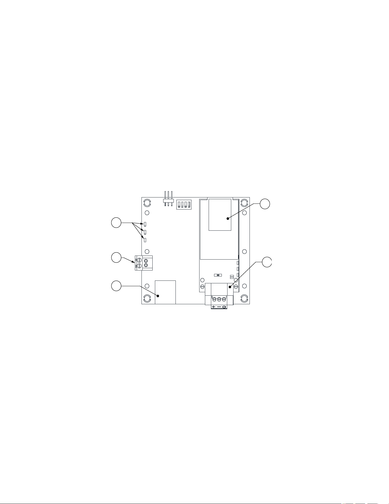
98
Network
NOTE: The board will reboot when altering certain factory settings.
Communication Module (Optional)
The Communication Module, PN: SCADA, is included in all CASlink equipped panels. It obtains
operational data from various connected components. This communication wiring is either RS-485
shielded twisted pair wiring or RJ45 Cat 5 Ethernet wiring.
BACnet
BACnet IP or BACnet MS/TP (Figure 52) compatibility can be implemented with this package through a
Protocessor, which is a BTL listed embedded Gateway configured to give a Building Management System
access to monitor and/or control a list of BACnet objects. The Protocessor is mounted and factory pre-
wired inside the Electrical Control Panel (ECP). Field connections to the Building Management System
(BMS) are shown on wiring schematics.
The Protocessor is preconfigured at the factory to use the field protocol of the Building Management
System in the specific jobsite. BACnet objects can only be accessed through the specified port and
protocol.
Figure 52 - BACnet
1
2
3
4
5
1. Status LEDs
• Green - Data Out
• Yellow - Data In
• Red - Power On
2. Power Supply 24V AC/DC
3. Cat 5 Cable to MUA Board.
4. Field RS485 Connection for BACnet MS/TP
5. Field Ethernet Connection for BACnet IP
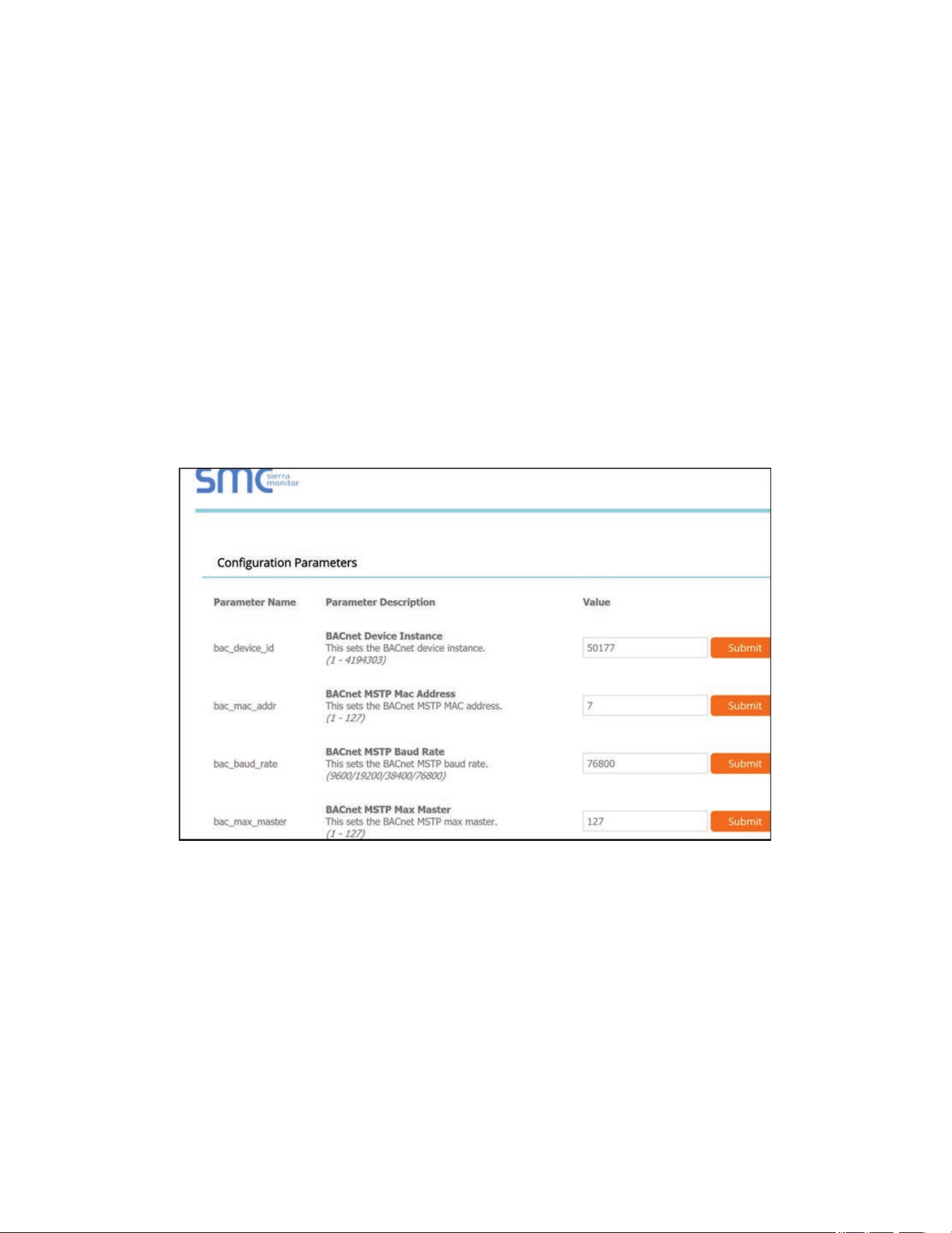
99
Device Instance, MAC Address, Baud Rate
Some applications may require that the Protocessor have a specific Device Instance, the default device
instance is 50,000. To change the Device Instance, you must access the Web Configurator by connecting
a computer to the Ethernet port of the Protocessor. The computer used must be assigned a static IP
address of 192.168.1.xxx and a subnet mask of 255.255.255.0.
To access the Web Configurator, type the IP address of the Protocessor in the URL of any web browser.
The default IP address of the Protocessor is 192.168.1.24. Once the landing page has loaded, if required,
log in using “admin” for the username and password. If the default “admin” password does not work, the
gateway should have a printed password on the module’s Ethernet port.
Go to the main configuration page, select “Configure” from the left-hand menu. Select “Profile
Configuration,” the following window shown in Figure 53 should appear.
The MAC address and Baud Rate, used by BACnet MTSP, are editable. The MAC address default is 127,
and the Baud Rate default is 38400.
If any changes are made, click on the submit button for each individual change. Each individual
change will require the system to restart.
Figure 53 - Configuration Parameters Page
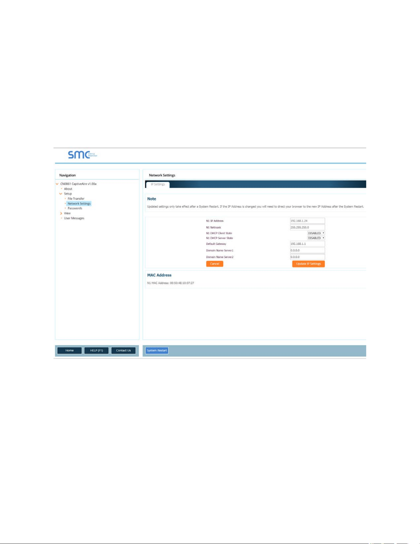
100
Changing the IP Address
Some BACnet IP applications may require changing the IP address of the Protocessor. To change the IP
address, go to the internal server by typing the default IP address of the Protocessor, 192.168.1.24, in the
URL field of any web browser. The computer used must have a static IP address of 192.168.1.xxx. The
window shown in Figure 54 appears. Click on the “Diagnostics and Debugging” button in the lower right
corner.
Click on “Setup” from the left-hand side menu and select “Network Settings.” The window shown in
Figure 54 will appear. You can now modify the IP address to whatever is required in the application. Once
the IP address has been modified, click on “Update IP Settings.”
Figure 54 - Network Settings Page
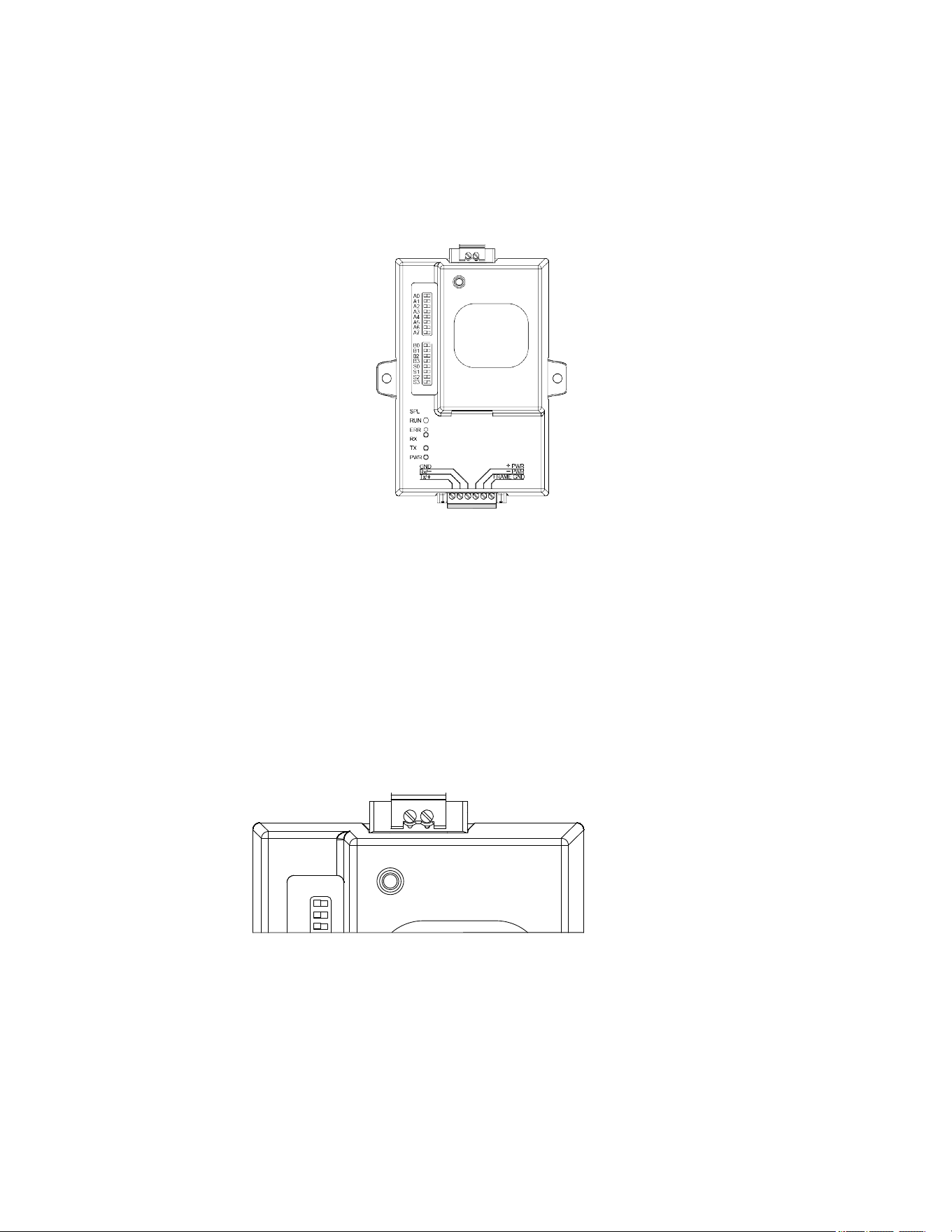
101
LonWorks
LonWorks compatibility (Figure 55) can be implemented on control packages through the ProtoNode, a
LonMark certified external Gateway configured to give a Building Management System access to monitor
and/or control a list of Network Variables. The ProtoNode is mounted and factory pre-wired inside the
Electrical Control Panel. Refer to schematics connections to the Building Management System are shown.
Figure 55 - LonWorks
Commissioning on a LonWorks Network
During the commissioning process by the LonWorks administrator (using a LonWorks Network
Management Tool), the user will be prompted to hit the Service Pin in the ProtoNode. This pin is located in
the front face, and it can be pressed by inserting a small screwdriver and tilting it towards the LonWorks
Port. Refer to Figure 56 for location of the “Service Pin.”
If an XIF file is required, it can be obtained by following these steps:
1. Set your computer’s static IP address to 192.168.1.xxx with a subnet mask of 255.255.255.0.
2. Run a Cat 5 connection from the ProtoNode’s Ethernet port to your computer.
3. On any web browser’s URL field, type 192.168.1.24/fserver.xif.
The web browser should automatically download the fserver.xif file or let you save it on your computer.
Save it as fserver.xif.
Figure 56 - LonWorks Service Pin
A0
A1
A2
S
E
R
V
I
C
E
P
I
N
NOTE: Insert Small Screwdriver.
Tilt Toward LonWorks Port To
Activate Service Pin.
102
DDC Control Points (BACnet)
Refer to “DDC Notes” on page 106 for more information.
Name ID Object Type Lon SNVT NAME Function Modbus Description
DDCHeatCommand (1) 1 Binary Value (BV) nviDDCHeat/nvoDDCHeat Control/Monitor 10000 Heating command. Requires heat tempering mode = DDC
DDCCoolCommand (1) 2 BV nviDDCCool1/nvoDDCCool Control/Monitor 10001 Cooling command. Requires heat tempering mode = DDC
DDCBlowerCommand (1) 3 BV nviDDCBlow/nvoDDCBlow Control/Monitor 10004
Blower command. Requires both heat and cool tempering mode = DDC
DDCModulation (1) 4 Analog Value (AV) nviDDCModHeat/nvoDDCModHeat Control/Monitor 10005
Heat modulation signal, 0-10V. 0V = low fire and 10V = high fire.
Requires heat tempering mode = DDC
DDCOccupiedOverride (4) 5 BV nviDDCOccOvrrd/nvoDDCOccOvrrd Control/Monitor 10006
Occupied override command, requires SchedulingEnabled = ON (1)
IntakeHeatOccSP (3) 6 AV nviInHeatOccSP/nvoInHeatOccSP Control/Monitor 16000 Intake Heating Occupied Setpoint
IntakeHeatUnoccSP (3) 7 AV nviInHeatUnocSP/nvoInHeatUnocSP Control/Monitor 16001 Intake Heating Unoccupied Setpoint
SpaceHeatOccSP (3) 8 AV
nviSpHeatOccSP/nvoSpHeatOccSP
Control/Monitor
16002 Space Heating Occupied Setpoint
SpaceHeatUnoccSP (3) 9 AV
nviSpHeatUnocSP/nvoSpHeatUnocSP
Control/Monitor
16003 Space Heating Unoccupied Setpoint
MinDischargeHeatOccSP (3) 10 AV
nviMinDHeatOccSP/nvoMinDHeatOccSP
Control/Monitor
16004 Min Discharge Heating when occupied, relevant only if heat tempering mode = space
MinDischargeHeatUnoccSP (3) 11 AV
nviMinDHeatUnoSP/nvoMinDHeatUnoSP
Control/Monitor
16005 Min Discharge Heating when unoccupied, relevant only if heat tempering mode = space
DischargeHeatOccSP (3) 12 AV
nviDisHeatOccSP/nvoDisHeatOccSP
Control/Monitor
16006 Discharge heating setpoint when occupied, requires heat tempering mode = discharge
DischargeHeatUnoccSP (3) 13 AV
nviDisHeatUnocSP/nvoDisHeatUnocSP
Control/Monitor
16007 Discharge heating setpoint when unoccupied, requires heat tempering mode = discharge
MaxDischargeHeatOccSP (3) 14 AV
nviMaxDHeatOccSP/nvoMaxDHeatOccSP
Control/Monitor
16008 Max Discharge Heating when occupied, relevant only if heat tempering mode = space
MaxDischargeHeatUnoccSP (3) 15 AV
nviMaxDHeatUnoSP/nvoMaxDHeatUnoSP
Control/Monitor
16009 Max Discharge Heating when unoccupied, relevant only if heat tempering mode = space
IntakeCoolOccSP (3) 16 AV
nviInCoolOccSP/nvoInCoolOccSP
Control/Monitor
16010 Intake Cooling Occupied Setpoint
IntakeCoolUnoccSP (3) 17 AV
nviInCoolUnocSP/nvoInCoolUnocSP
Control/Monitor
16011 Intake Cooling Unoccupied Setpoint
SpaceCoolOccSP (3) 18 AV
nviSpCoolOccSP/nvoSpCoolOccSP
Control/Monitor
16012 Space Cooling Occupied Setpoint
SpaceCoolUnoccSP (3) 19 AV
nviSpCoolUnocSP/nvoSpCoolUnocSP
Control/Monitor
16013 Space Cooling Unoccupied Setpoint
MinDischargeCoolOccSP (3) 20 AV nviMinDCoolOccSP/nvoMinDCoolOccSP Control/Monitor 16014
Min Discharge Cooling setpoint when occupied,
relevant only if cool tempering mode = space
MinDischargeCoolUnoccSP (3) 21 AV nviMinDCoolUnoSP/nvoMinDCoolUnoSP Control/Monitor 16015
Min Discharge Cooling setpoint when unoccupied,
relevant only if cool tempering mode = space
DischargeCoolOccSP (3) 22 AV nviDisCoolOccSP/nvoDisCoolOccSP Control/Monitor 16016
Discharge Cooling setpoint when occupied,
relevant only if cool tempering mode = discharge
DischargeCoolUnoccSP (3) 23 AV nviDisCoolUnocSP/nvoDisCoolUnocSP Control/Monitor 16017
Discharge Cooling setpoint when unoccupied,
relevant only if cool tempering mode = discharge
MaxDischargeCoolOccSP (3) 24 AV nviMaxDCoolOccSP/nvoMaxDCoolOccSP Control/Monitor 16018
Max Discharge Cooling setpoint when occupied,
relevant only if cool tempering mode = space
MaxDischargeCoolUnoccSP (3) 25 AV nviMaxDCoolUnoSP/nvoMaxDCoolUnoSP Control/Monitor 16019
Max Discharge Cooling setpoint when unoccupied,
relevant only if cool tempering mode = space
RoomOverrideOccSP (3) 26 AV
nviRoomOvOccSP/nvoRoomOvOccSP
Control/Monitor
16020 Room Override Occupied Setpoint
RoomOverrideUnoccSP (3) 27 AV
nviRoomOvUnocSP/nvoRoomOvUnocSP
Control/Monitor
16021 Room Override Unoccupied Setpoint
FirestatIntakeSP (3) 28 AV nviFireIntakeSP/nvoFireIntakeSP Control/Monitor 16022 Firestat Intake Setpoint
FirestatDischargeSP (3) 29 AV nviFireDischSP/nvoFireDischSP Control/Monitor 16023 Firestat Discharge Setpoint
FreezestatSP (3) 30 AV nviFreezeSP/nvoFreezeSP Control/Monitor 16024 Freezestat Setpoint
OverheatDischargeSP (3) 31 AV nviOheatDisSP/nvoOheatDisSP Control/Monitor 16025 Overheat Discharge Setpoint
CabinetHeatSP (3) 32 AV nviCabHeatSP/nvoCabHeatSP Control/Monitor 16026 Cabinet Heat Setpoint
FurnaceDrainHeatSP (3) 33 AV nviFDrainHeatSP/nvoFDrainHeatSP Control/Monitor 16027 Furnace Drain Heat Setpoint
IntakeRhOccSP (3) 34 AV nviInRhOccSP/nvoInRhOccSP Control/Monitor 16028 Intake Relative Humidity Occupied Setpoint
IntakeRhUnoccSP (3) 35 AV nviInRhUnoccSP/nvoInRhUnoccSP Control/Monitor 16029 Intake Relative Humidity Unoccupied Setpoint
SpaceRhOccSP (3) 36 AV nviSpRhOccSP/nvoSpRhOccSP Control/Monitor 16030 Space Relative Humidity Occupied Setpoint
SpaceRhUnoccSP (3) 37 AV nviSpRhUnoccSP/nvoSpRhUnoccSP Control/Monitor 16031 Space Relative Humidity Unoccupied Setpoint
DischargeRhOccSP (3) 38 AV nviDisRhOccSP/nvoDisRhOccSP Control/Monitor 16032 Discharge Relative Humidity Occupied Setpoint
DischargeRhUnoccSP (3) 39 AV nviDisRhUnoccSP/nvoDisRhUnoccSP Control/Monitor 16033 Discharge Relative Humidity Unoccupied Setpoint
IntakeDpOccSP (3) 40 AV nviInDpOccSP/nvoInDpOccSP Control/Monitor 16034 Intake Dewpoint Occupied Setpoint
IntakeDpUnoccSP (3) 41 AV nviInDpUnoccSP/nvoInDpUnoccSP Control/Monitor 16035 Intake Dewpoint Unoccupied Setpoint
SpaceDpOccSP (3) 42 AV nviSpDpOccSP/nvoSpDpOccSP Control/Monitor 16036 Space Dewpoint Occupied Setpoint
SpaceDpUnoccSP (3) 43 AV nviSpDpUnoccSP/nvoSpDpUnoccSP Control/Monitor 16037 Space Dewpoint Unoccupied Setpoint
DischargeDpOccSP (3) 44 AV nviDisDpOccSP/nvoDisDpOccSP Control/Monitor 16038 Discharge Dewpoint Occupied Setpoint
DischargeDpUnoccSP (3) 45 AV nviDisDpUnoccSP/nvoDisDpUnoccSP Control/Monitor 16039 Discharge Dewpoint Unoccupied Setpoint
ScheduleSundayAStart (4) 46 AV
nviSundayAStart/nvoSundayAStart
Control/Monitor
16040 Daily schedule start/end time in minutes
ScheduleSundayAEnd (4) 47 AV
nviSundayAEnd/nvoSundayAEnd
Control/Monitor
16041 Daily schedule start/end time in minutes
ScheduleSundayBStart (4) 48 AV
nviSundayBStart/nvoSundayBStart
Control/Monitor
16042 Daily schedule start/end time in minutes
ScheduleSundayBEnd (4) 49 AV
nviSundayBEnd/nvoSundayBEnd
Control/Monitor
16043 Daily schedule start/end time in minutes
ScheduleSundayCStart (4) 50 AV
nviSundayCStart/nvoSundayCStart
Control/Monitor
16044 Daily schedule start/end time in minutes
ScheduleSundayCEnd (4) 51 AV
nviSundayCEnd/nvoSundayCEnd
Control/Monitor
16045 Daily schedule start/end time in minutes
ScheduleMondayAStart (4) 52 AV
nviMondayAStart/nvoMondayAStart
Control/Monitor
16046 Daily schedule start/end time in minutes
ScheduleMondayAEnd (4) 53 AV
nviMondayAEnd/nvoMondayAEnd
Control/Monitor
16047 Daily schedule start/end time in minutes
ScheduleMondayBStart (4) 54 AV
nviMondayBStart/nvoMondayBStart
Control/Monitor
16048 Daily schedule start/end time in minutes
ScheduleMondayBEnd (4) 55 AV
nviMondayBEnd/nvoMondayBEnd
Control/Monitor
16049 Daily schedule start/end time in minutes
ScheduleMondayCStart (4) 56 AV
nviMondayCStart/nvoMondayCStart
Control/Monitor
16050 Daily schedule start/end time in minutes
ScheduleMondayCEnd (4) 5
7 AV
nviMondayCEnd/nvoMondayCEnd
Control/Monitor
16051 Daily schedule start/end time in minutes
ScheduleTuesdayAStart (4) 58 AV
nviTuesdayAStart/nvoTuesdayAStart
Control/Monitor
16052 Daily schedule start/end time in minutes
ScheduleTuesdayAEnd (4) 59 AV
nviTuesdayAEnd/nvoTuesdayAEnd
Control/Monitor
16053 Daily schedule start/end time in minutes
ScheduleTuesdayBStart (4) 60 AV
nviTuesdayBStart/nvoTuesdayBStart
Control/Monitor
16054 Daily schedule start/end time in minutes
103
ScheduleTuesdayBEnd (4) 61 AV
nviTuesdayBEnd/nvoTuesdayBEnd
Control/Monitor
16055 Daily schedule start/end time in minutes
ScheduleTuesdayCStart (4) 62 AV
nviTuesdayCStart/nvoTuesdayCStart
Control/Monitor
16056 Daily schedule start/end time in minutes
ScheduleTuesdayCEnd (4) 63 AV
nviTuesdayCEnd/nvoTuesdayCEnd
Control/Monitor
16057 Daily schedule start/end time in minutes
ScheduleWednesdayAStart (4) 64 AV
nviWedAStart/nvoWedAStart
Control/Monitor
16058 Daily schedule start/end time in minutes
ScheduleWednesdayAEnd (4) 65 AV
nviWedAEnd/nvoWedAEnd
Control/Monitor
16059 Daily schedule start/end time in minutes
ScheduleWednesdayBStart (4) 66 AV
nviWedBStart/nvoWedBStart
Control/Monitor
16060 Daily schedule start/end time in minutes
ScheduleWednesdayBEnd (4) 67 AV
nviWedBEnd/nvoWedBEnd
Control/Monitor
16061 Daily schedule start/end time in minutes
ScheduleWednesdayCStart (4) 68 AV
nviWedCStart/nvoWedCStart
Control/Monitor
16062 Daily schedule start/end time in minutes
ScheduleWednesdayCEnd (4) 69 AV
nviWedCEnd/nvoWedCEnd
Control/Monitor
16063 Daily schedule start/end time in minutes
ScheduleThursdayAStart (4) 70 AV
nviThursAStart/nvoThursAStart
Control/Monitor
16064 Daily schedule start/end time in minutes
ScheduleThursdayAEnd (4) 71 AV
nviThursAEnd/nvoThursAEnd
Control/Monitor
16065 Daily schedule start/end time in minutes
ScheduleThursdayBStart (4) 72 AV
nviThursBStart/nvoThursBStart
Control/Monitor
16066 Daily schedule start/end time in minutes
ScheduleThursdayBEnd (4) 73 AV
nviThursBEnd/nvoThursBEnd
Control/Monitor
16067 Daily schedule start/end time in minutes
ScheduleThursdayCStart (4) 74 AV
nviThursCStart/nvoThursCStart
Control/Monitor
16068 Daily schedule start/end time in minutes
ScheduleThursdayCEnd (4) 75 AV
nviThursCEnd/nvoThursCEnd
Control/Monitor
16069 Daily schedule start/end time in minutes
ScheduleFridayAStart (4) 76 AV
nviFridayAStart/nvoFridayAStart
Control/Monitor
16070 Daily schedule start/end time in minutes
ScheduleFridayAEnd (4) 77 AV
nviFridayAEnd/nvoFridayAEnd
Control/Monitor
16071 Daily schedule start/end time in minutes
ScheduleFridayBStart (4) 78 AV
nviFridayBStart/nvoFridayBStart
Control/Monitor
16072 Daily schedule start/end time in minutes
ScheduleFridayBEnd (4) 79 AV
nviFridayBEnd/nvoFridayBEnd
Control/Monitor
16073 Daily schedule start/end time in minutes
ScheduleFridayCStart (4) 80 AV
nviFridayCStart/nvoFridayCStart
Control/Monitor
16074 Daily schedule start/end time in minutes
ScheduleFridayCEnd (4) 81 AV
nviFridayCEnd/nvoFridayCEnd
Control/Monitor
16075 Daily schedule start/end time in minutes
ScheduleSaturdayAStart (4) 82 AV
nviSatAStart/nvoSatAStart
Control/Monitor
16076 Daily schedule start/end time in minutes
ScheduleSaturdayAEnd (4) 83 AV
nviSatAEnd/nvoSatAEnd
Control/Monitor
16077 Daily schedule start/end time in minutes
ScheduleSaturdayBStart (4) 84 AV
nviSatBStart/nvoSatBStart
Control/Monitor
16078 Daily schedule start/end time in minutes
ScheduleSaturdayBEnd (4) 85 AV
nviSatBEnd/nvoSatBEnd
Control/Monitor
16079 Daily schedule start/end time in minutes
ScheduleSaturdayCStart (4) 86 AV
nviSatCStart/nvoSatCStart
Control/Monitor
16080 Daily schedule start/end time in minutes
ScheduleSaturdayCEnd (4) 87 AV
nviSatCEnd/nvoSatCEnd
Control/Monitor
16081 Daily schedule start/end time in minutes
BlowerManualFreqOcc (2) 88 AV
nviBlowManFreqOc/nvoBlowManFreqOc
Control/Monitor
16082 VFD frequency when occupied, requires blower control = VFD manual
BlowerManualFreqUnocc (2) 89 AV
nviBlowManFreqUn/nvoBlowManFreqUn
Control/Monitor
16083 VFD frequency when unoccupied, requires blower control = VFD manual
BlowerManualPwmRateOcc (2) 90 AV
nviBlowManPwmOc/nvoBlowManPwmOc
Control/Monitor
16084 ECM speed when occupied, requires blower control = ECM manual
BlowerManualPwmRateUnocc (2) 91 AV
nviBlowManPwmUn/nvoBlowManPwmUn
Control/Monitor
16085 ECM speed when unoccupied, requires blower control = ECM manual
MixingBoxManualOAOcc (2) 92 AV
nviMixBoxManOAOc/nvoMixBoxManOAOc
Control/Monitor
16087
Mixing Box Outdoor Air Percent during occupied times, requires mixing box mode
= outdoor air percent
MixingBoxManualOAUnocc (2) 93 AV
nviMixBoxManOAUn/nvoMixBoxManOAUn
Control/Monitor
16088
Mixing Box Outdoor Air Percent during unoccupied times, requires mixing box mode
= outdoor air percent
EconomizerTempSPOcc (2) 94 AV nviEcoTempSPOcc/nvoEcoTempSPOcc Control/Monitor 16095 Economizer Temperature Setpoint Occupied
EconomizerTempSPUnocc (2) 95 AV nviEcoTemSPUnocc/nvoEcoTemSPUnocc Control/Monitor 16096 Economizer Temperature Setpoint Unoccupied
EconomizerTempBandOcc (2) 96 AV nviEcoTemBandOcc/nvoEcoTemBandOcc Control/Monitor 16097 Economizer Temperature Band Setpoint Occupied
EconomizerTempBandUnocc (2) 97 AV nviEcoTempBUnocc/nvoEcoTempBUnocc Control/Monitor 16098 Economizer Temperature Band Setpoint Unoccupied
EconomizerTotalBandOcc (2) 98 AV nviEcoTotBandOcc/nvoEcoTotBandOcc Control/Monitor 16099 Economizer Temperature Total Band Setpoint Occupied
EconomizerTotalBandUnocc (2) 99 AV nviEcoTotBUnocc/nvoEcoTotBUnocc Control/Monitor 16100 Economizer Temperature Total Band Setpoint Unoccupied
EconomizerRhSPOcc (2) 100 AV nviEcoRhSPOcc/nvoEcoRhSPOcc Control/Monitor 16101 Economizer Relative Humidity Setpoint Occupied
EconomizerRhSPUnocc (2) 101 AV nviEcoRhSPUnocc/nvoEcoRhSPUnocc Control/Monitor 16102 Economizer Relative Humidity Setpoint Unoccupied
MixingBoxManualVoltsOcc (2) 102 AV
nviMixBoxManVOc/nvoMixBoxManVOc
Control/Monitor
16106 Mixing Box damper voltage during occupied times, requires mixing box mode = manual
MixingBoxManualVoltsUnocc (2) 103 AV
nviMixBoxManVUn/nvoMixBoxManVUn
Control/Monitor
16107 Mixing Box damper voltage during unoccupied times, requires mixing box mode = manual
BlowerPsSpLowOcc (2) 104 AV nviBlowPsSpLOcc/nvoBlowPsSpLOcc Control/Monitor 16108 Blower Low Static Pressure Setting Occupied
BlowerPsSpLowUnocc (2) 105 AV nviBlowPsSpLUn/nvoBlowPsSpLUn Control/Monitor 16109 Blower Low Static Pressure Setting Unoccupied
BlowerPsSpHighOcc (2) 106 AV nviBlowPsSpHOcc/nvoBlowPsSpHOcc Control/Monitor 16110 Blower High Static Pressure Setting Occupied
BlowerPsSpHighUnocc (2) 107 AV nviBlowPsSpHUn/nvoBlowPsSpHUn Control/Monitor 16111 Blower High Static Pressure Setting Unoccupied
DryModeDischTempSPOcc (3) 108 AV
nviDMDisTSPOcc/nvoDMDisTSPOcc
Control/Monitor
16112 Dry Mode Discharge Occupied Setpoint
DryModeDischTempSPUnocc (3) 109 AV nviDMDisTSPUn/nvoDMDisTSPUn Control/Monitor
16113 Dry Mode Discharge Unoccupied Setpoint
OaResetLowTempSp (3) 110 AV nviOaRLTempSp/nvoOaRLTempSp Control/Monitor 16114 Outdoor Air Reset Low Temperature Setpoint
OaResetHighTempSp (3) 111 AV nviOaRHTempSp/nvoOaRHTempSp Control/Monitor 16115 Outdoor Air Reset High Temperature Setpoint
OaResetHeatDischTempSp (3) 112 AV nviOaRHeatDTSp/nvoOaRHeatDTSp Control/Monitor 16116 Outdoor Air Reset Heat Discharge Temperature Setpoint
OaResetCoolDischTempSp (3) 113 AV nviOaRCoolDTSp/nvoOaRCoolDTSp Control/Monitor 16136 Outdoor Air Reset Cool Discharge Temperature Setpoint
OaResetHeatSpaceTempSp (3) 114 AV nviOaRHeatSTSp/nvoOaRHeatSTSp Control/Monitor 16119 Outdoor Air Reset Heat Space Temperature Setpoint
OaResetCoolSpaceTempSp (3) 115 AV nviOaRCoolSTSp/nvoOaRCoolSTSp Control/Monitor 16118 Outdoor Air Reset Cool Space Temperature Setpoint
CO2SensorPpmMin (5) 116 AV nviCo2PpmMin/nvoCo2PpmMin Control/Monitor 16120 CO2 PPM level at 0V
CO2SensorPpmMax (5) 117 AV nviCo2PpmMax/nvoCo2PpmMax Control/Monitor
16121 C
O2 PPM level at 10V
CO2ThresholdLimitOcc (5) 118 AV nviCO2LimitOcc/nvoCO2LimitOcc Control/Monitor 16122 CO2 sensor threshold limit for the fan/damper to operate when occupied
CO2ThresholdLimitUnocc (5) 119 AV nviCO2LimitUn/nvoCO2LimitUn Control/Monitor 16141 CO2 sensor threshold limit for the fan/damper to operate when unoccupied
DynamicSpDiff (3) 120 AV nviDynSpDiff/nvoDynSpDiff Control/Monitor 16123 Dynamic Setpoint Differential
DynamicSpOffset (3) 121 AV nviDynSpOffset/nvoDynSpOffset Control/Monitor 16124 Dynamic Setpoint Differential Offset
DynamicSpHeatOa (3) 122 AV nviDynSpHeatOa/nvoDynSpHeatOa Control/Monitor 16125 Dynamic Setpoint Heat Outdoor Air
Name ID Object Type Lon SNVT NAME Function Modbus Description
104
DynamicSpCoolOa (3) 123 AV nviDynSpCoolOa/nvoDynSpCoolOa Control/Monitor 16126 Dynamic Setpoint Cool Outdoor Air
ErvWheelSpeed (2) 124 AV nviErvWheelSpeed/nvoErvWheelSpeed Control/Monitor 16127 Energy Wheel Speed Setting
ErvExhaustFanSpeedOcc (2) 125 AV nviErvEFSpeedOcc/nvoErvEFSpeedOcc Control/Monitor 16128 Energy Wheel Exhaust Fan Speed Occupied
ErvExhaustFanSpeedUnocc (2) 126 AV nviErvEFSpeedUn/nvoErvEFSpeedUn Control/Monitor 16129 Energy Wheel Exhaust Fan Speed Unoccupied
ErvExhaustLowPsSpOcc (2) 127 AV nviErvExLPsSpOcc/nvoErvExLPsSpOcc Control/Monitor 16130 Energy Wheel Exhaust Low Pressure Setpoint Occupied
ErvExhaustLowPsSpUnocc (2) 128 AV nviErvExLPsSpUn/nvoErvExLPsSpUn Control/Monitor 16131 Energy Wheel Exhaust Low Pressure Setpoint Unoccupied
ErvExhaustHighPsSpOcc (2) 129 AV nviErvExHPsSpOcc/nvoErvExHPsSpOcc Control/Monitor 16132 Energy Wheel Exhaust High Pressure Setpoint Occupied
ErvExhaustHighPsSpUnocc (2) 130 AV nviErvExHPsSpUn/nvoErvExHPsSpUn Control/Monitor 16133 Energy Wheel Exhaust High Pressure Setpoint Unoccupied
CO2OverrideHighLimitOcc (2) 131 AV nviCO2OrHighOcc/nvoCO2OrHighOcc Control/Monitor 16134 CO2 high limit setting at which fan/damper will operate occupied
CO2OverrideLowLimitOcc (2) 132 AV nviCO2OrLowOcc/nvoCO2OrLowOcc Control/Monitor 16135 CO2 low limit setting at which fan/damper will operate occupied
CO2OverrideHighLimitUnocc (2) 133 AV nviCO2OrHighUn/nvoCO2OrHighUn Control/Monitor 16143 CO2 high limit setting at which fan/damper will operate unoccupied
CO2OverrideLowLimitUnocc (2) 134 AV nviCO2OrLowUn/nvoCO2OrLowUn Control/Monitor 16142 CO2 low limit setting at which fan/damper will operate unoccupied
DryModeOASP (3) 135 AV nviDryModeOASP/nvoDryModeOASP Control/Monitor 16137 Dry Mode Outdoor Air Setpoint
DryModeCoolSP (3) 136 AV nviDryModeCoolSP/nvoDryModeCoolSP Control/Monitor 16138 Dry Mode Cool Setpoint
PoweredExhaustManVoltsOcc (2) 137 AV nviEFManPWMOcc/nvoEFManPWMOcc Control/Monitor 16139 Powered Exhaust PWM Setpoint Occupied
PoweredExhaustManVoltsUnocc (2) 138 AV nviEFManPWMUnocc/nvoEFManPWMUnocc Control/Monitor 16140 Powered Exhaust PWM Setpoint Unoccupied
UnitStatus (5) 139 Analog Input (AI) nvoCurrentState Monitor Only 2083
HVAC State (Idle = 0, Blower = 1, Heating = 2, Cooling = 3)
CurrentOccupiedStatus (5) 140 AI nvoOccStatus Monitor Only 2140
Occupancy status, occupied = 1, unoccupied = 0
CalculateAverageSpaceTemp (5) 141 AI nvoAvgSpaceTemp Monitor Only 2144 Average Space Temperature
Vfd571ActualFreq (5) 142 AI nvoBlowVFDFreq Monitor Only 2146 Blower VFD Frequency
Vfd571MotorCurrent (5) 143 AI nvoBlowVFDAmps Monitor Only 2150 Blower VFD Current
Vfd571OutputPower (5) 144 AI nvoBlowVFDPower Monitor Only 2152 Blower VFD Power
CalculatedAverageRh (5) 145 AI
nvoAvgRh
Monitor Only
2190 Average space relative humidity
OutdoorStatTemp (5) 146 AI
nvoOutdoorTemp
Monitor Only
9057 Outdoor Temperature
ReturnStatTemp (5) 147 AI
nvoReturnTemp
Monitor Only
9058 Return Temperature
DischargeStatTemp (5) 148 AI
nvoDischargeTemp
Monitor Only
9059 Discharge Temperature
IntakeStatTemp (5) 149 AI
nvoIntakeTemp
Monitor Only
9060 Intake Temperature
SpaceStatTemp (5) 150 AI
nvoSpaceTemp
Monitor Only
9061 Space Temperature (thermistor)
Hmi1Temp (5) 151 AI
nvoHmi1Temp
Monitor Only
9063 Unit HMI temperature
Hmi2Temp (5) 152 AI
nvoHmi2Temp
Monitor Only
9064 Remote HMI 1 Temperature
Hmi3Temp (5) 153 AI
nvoHmi3Temp
Monitor Only
9065 Remote HMI 2 Temperature
Hmi4Temp (5) 154 AI
nvoHmi4Temp
Monitor Only
9066 Remote HMI 3 Temperature
Hmi5Temp (5) 155 AI
nvoHmi5Temp
Monitor Only
9067 Remote HMI 4 Temperature
SuctionLineTemp (5) 156 AI nvoSucLineTemp Monitor Only 9069 Suction Line Temperature
LiquidLineTemp (5) 157 AI nvoLiqLineTemp Monitor Only 9070 Liquid Line Temperature
EvapIndoorCoilTemp (5) 158 AI nvoEvapCoilTemp Monitor Only 9071 Evaporator Coil Temperature
CondOutdoorCoilTemp (5) 159 AI nvoOutCoilTemp Monitor Only 9072 Condenser Coil Temperature
CompressorDischargeTemp (5) 160 AI nvoCompDisTemp Monitor Only 9073 Compressor Discharge Temperature
IntakeRh (5) 161 AI
nvoIntakeRh
Monitor Only
9078 Intake Sensor Relative Humidity
SpaceRh (5) 162 AI
nvoSpaceRh
Monitor Only
9079 Space Sensor Relative Humidity
OutdoorRh (5) 163 AI nvoOutdoorRh Monitor Only 1048
Outdoor Sensor Relative Humidity
DischargeRh (5) 164 AI nvoDischargeRh Monitor Only 9090
Discharge Sensor Relative Humidity
ReturnRh (5) 165 AI nvoReturnRh Monitor Only 9091
Return Sensor Relative Humidity
SuctionLinePs (5) 166 AI nvoSucLinePs Monitor Only 9092 Suction Line Pressure
DischargeLinePs (5) 167 AI nvoDisLinePs Monitor Only 9093 Discharge Line Pressure
LiquidLinePs (5) 168 AI nvoLiqLinePs Monitor Only 9094 Liquid Line Pressure
Hmi1Rh (5) 169 AI
nvoHmi1Rh
Monitor Only
9097 Unit HMI Relative Humidity
Hmi2Rh (5) 170 AI
nvoHmi2Rh
Monitor Only
9098 Remote HMI 1 Relative Humidity
Hmi3Rh (5) 171 AI
nvoHmi3Rh
Monitor Only
9099 Remote HMI 2 Relative Humidity
Hmi4Rh (5) 172 AI
nvoHmi4Rh
Monitor Only
9100 Remote HMI 3 Relative Humidity
Hmi5Rh (5) 173 AI
nvoHmi5Rh
Monitor Only
9101 Remote HMI 4 Relative Humidity
SupplyPwmRate (5) 174 AI nvoSupplyPwm Monitor Only 1039 PWM Signal to Supply Fan
ExhaustPwmRate (5) 175 AI nvoExhaustPwm Monitor Only 1040 PWM Signal to Exhaust Fan
CondFan1PwmRate (5) 176 AI nvoCond1PwmRate Monitor Only 1041 PWM Signal to set #1 of Condensing Fans
CondFan2PwmRate (5) 177 AI nvoCond2PwmRate Monitor Only 1042 PWM Signal to set #2 of Condensing Fans
ModulatingGasValve1Output (5) 178 AI nvoMGV1Output Monitor Only 1046
Controller output to the modulating gas valve #1. 0% = Low Fire, 100% = High Fire
ModulatingGasValve2Output (5) 179 AI nvoMGV2Output Monitor Only 1047
Controller output to the modulating gas valve #2. 0% = Low Fire, 100% = High Fire
AdjustableDamperOutput (5) 1
80 AI nvoDampOutput Monitor Only 9085 Output Voltage to Damper
ElectricHeaterOutput (5) 181 AI nvoElecHeatOut Monitor Only 1051 Output Voltage to Electric Heater
OilBoostActiveFlag (5) 182 Binary Input (BI) nvoOilBoostON Monitor Only 4000 0 = Oil Boost Not Active, 1 = Oil Boost Active
ReheatActiveFlag (5) 183 BI nvoReheatON Monitor Only 4001 0 = Reheat Not Active, 1 = Reheat Active
DefrostActiveFlag (5) 184 BI nvoDefrostON Monitor Only 4002 0 = Defrost Not Active, 1 = Defrost Active
PumpdownOffActiveFlag (5) 185 BI nvoPumpOFFOn Monitor Only 4003 0 = Pumpdown Off Not Active, 1 = Pumpdown Off Active
Name ID Object Type Lon SNVT NAME Function Modbus Description
105
PumpdownOnActiveFlag (5) 186 BI nvoPumpONOn Monitor Only 4004 0 = Pumpdown On Not Active, 1 = Pumpdown On Active
ReheatValvePosition (5) 187 AI nvoReheatPos Monitor Only 4028 Percentage of the Reheat Valve’s Position
EevValvePosition (5) 188 AI nvoEevValvePos Monitor Only 4029 Percentage of the EEV Valve’s Position
IntakeDpActual (5) 189 AI nvoInDpActual Monitor Only 4030 Actual Intake Dew Point Reading
SpaceDpActual (5) 190 AI nvoSpDpActual Monitor Only 4032 Actual Space Dew Point Reading
CompressorPower (5) 191 AI nvoCompPower Monitor Only 2152 Compressor Power Reading
CompressorFrequency (5) 192 AI nvoCompFreq Monitor Only 2157 Compressor Frequency Reading
CompressorCurrent (5) 193 AI nvoCompAmps Monitor Only 2150 Compressor Current Reading
ERVExhaustAirRh (5) 194 AI nvoERVExhRh Monitor Only 4077 ERV Exhaust Air Relative Humidity
ERVWheelSupplyPsInches (5) 195 AI nvoERVSupplyPs Monitor Only 4078 ERV Wheel Supply Pressure Differential
ERVWheelExhPsInches (5) 196 AI nvoERVExhPs Monitor Only 4081 ERV Wheel Exhaust Pressure Differential
ERVExhCtrlVolts (5) 197 AI nvoERVExhVolts Monitor Only 4082 0-10 Volt ERV Exhaust Speed Control
ERVExhAirTemp (5) 198 AI nvoERVExhTemp Monitor Only 4083 ERV Exhaust Air Temperature
ERVOutsideAirRh (5) 199 AI nvoERVOARh Monitor Only 4084 ERV Outside Air Relative Humidity
ERVOutsideAirTemp (5) 200 AI nvoERVOATemp Monitor Only 4085 ERV Outside Air Temperature
ERVExhBlowerDutyCycle (5) 201 AI nvoERVExhDuty Monitor Only 4087 PWM Signal to Exhaust Fan ECM
ERVExhBlowerPwmEnable (5) 202 BI nvoERVExhPwmEn Monitor Only 4088 0 = Disable, 1 = Enable
ERVWheelDutyCycle (5) 203 AI nvoERVWheelDuty Monitor Only 4089 PWM Signal to ERV Wheel ECM
ERVWheelPwmEnable (5) 204 BI nvoERVWheelPwmEn Monitor Only 4090 0 = Disable, 1 = Enable
ERVState (5) 205 AI nvoERVState Monitor Only 4113 0 = Idle, 5 = Defrost, 6 = Clean, 7 = Test, 8 = Stop
ERVAppliedWheelSpeed (5) 206 AI nvoERVAppWSpeed Monitor Only 4114 Desired Energy Wheel Fan Speed
ERVAppliedExhFanSpeed (5) 207 AI nvoERVAppEFSpeed Monitor Only 4115 Desired ERV Exhaust Fan Speed
Subcool (5) 208 AI nvoSubcool Monitor Only 4132 Subcool Readings
Superheat (5) 209 AI nvoSuperheat Monitor Only 4133 Superheat Readings
ActiveFault1 (5) 210 AI
nvoActiveFault0
Monitor Only
30501 Active Fault Code (see fault code table)
ActiveFault2 (5) 211 AI
nvoActiveFault1
Monitor Only
30502 Active Fault Code (see fault code table)
ActiveFault3 (5) 212 AI
nvoActiveFault2
Monitor Only
30503 Active Fault Code (see fault code table)
ActiveFault4 (5) 213 AI
nvoActiveFault3
Monitor Only
30504 Active Fault Code (see fault code table)
ActiveFault5 (5) 214 AI
nvoActiveFault4
Monitor Only
30505 Active Fault Code (see fault code table)
ActiveFault6 (5) 215 AI
nvoActiveFault5
Monitor Only
30506 Active Fault Code (see fault code table)
SchedulingEnabledFlag (4) 216 BV nviSchedEnabled/nvoSchedEnabled Control/Monitor 15016
Enable scheduling. Not an occupancy command. Refer to ID 5 “DDCOccupiedOverride”
to toggle between occupied/unoccupied
HeatTemperModeOcc (2) 217 AV nviHeatModeOcc/nvoHeatModeOcc Control/Monitor 15055
Heat tempering mode during occupied time
HeatTemperModeUnocc (2) 218 AV nviHeatModeUnocc/nvoHeatModeUnocc Control/Monitor 15056
Heat tempering mode during unoccupied time
CoolTemperModeOcc (2) 219 AV nviCoolModeOcc/nvoCoolModeOcc Control/Monitor 15057
Cool tempering mode during occupied time
CoolTemperModeUnocc (2) 220 AV nviCoolModeUnocc/nvoCoolModeUnocc Control/Monitor 15058
Cool tempering mode during unoccupied time
ActivateOnOcc (2) 221 AV nviActivateOcc/nvoActivateOcc Control/Monitor 15059
"Activate based on" during occupied time
ActivateOnUnocc (2) 222 AV nviActivateUnocc/nvoActivateUnocc Control/Monitor 15060
"Activate based on" during unoccupied time
BlowerModeOcc (2) 223 AV nviBlowModeOcc/nvoBlowModeOcc Control/Monitor 15074
Blower mode during occupied times
BlowerModeUnocc (2) 224 AV nviBlowModeUnocc/nvoBlowModeUnocc Control/Monitor 15075
Blower mode during unoccupied times
MixingBoxMode (2) 225 AV nviMBMode/nvoMBMode Control/Monitor 15089 Mixing Box mode selection
ReheatDPAdjOcc (2) 226 AV nviDPAdjOcc/nvoDPAdjOcc Control/Monitor 15154 Reheat Dew Point adjust setpoint value when occupied
ReheatDPAdjUnocc (2) 227 AV nviDPAdjUnocc/nvoDPAdjUnocc Control/Monitor 15155 Reheat Dew Point adjust setpoint value when unoccupied
BlowerVfdMinFreqOcc (2) 228 AV nviVFDMinFreqOcc/nvoVFDMinFreqOcc Control/Monitor 15078
Min blower VFD Frequency when occupied
BlowerVfdMinFreqUnocc (2) 229 AV nviVFDMinFUnocc/nvoVFDMinFUnocc Control/Monitor 15079
Min blower VFD Frequency when unoccupied
BlowerVfdMaxFreqOcc (2) 230 AV nviVFDMaxFreqOcc/nvoVFDMaxFreqOcc Control/Monitor 15080
Max blower VFD Frequency when occupied
BlowerVfdMaxFreqUnocc (2) 231 AV nviVFDMaxFUnocc/nvoVFDMaxFUnocc Control/Monitor 15081
Max blower VFD Frequency when unoccupied
BlowerPwmMinRateOcc (2) 232 AV nviPWMMinOcc/nvoPWMMinOcc Control/Monitor 15082
Min blower ECM speed when occupied
BlowerPwmMinRateUnocc (2) 233 AV nviPWMMinUnocc/nvoPWMMinUnocc Control/Monitor 15083
Min blower ECM speed when unoccupied
BlowerPwmMaxRateOcc (2) 234 AV nviPWMMaxOcc/nvoPWMMaxOcc Control/Monitor 15084
Max blower ECM speed when occupied
BlowerPwmMaxRateUnocc (2) 235 AV nviPWMMaxUnocc/nvoPWMMaxUnocc Control/Monitor 15085
Max blower ECM speed when unoccupied
MixingBoxMinOAPercentOcc (2) 236 AV nviMBMinOAPerOcc/nvoMBMinOAPerOcc Control/Monitor 15092
Min occupied outdoor air percent when mixing box mode = outdoor air percent
MixingBoxMinOAPercentUnocc (2) 237 AV nviMBMinOAPerUn/nvoMBMinOAPerUn Control/Monitor 15093
Min unoccupied outdoor air percent when mixing box mode = outdoor air percent
MixingBoxMaxOAPercentOcc (2) 238 AV nviMBMaxOAPerOcc/nvoMBMaxOAPerOcc Control/Monitor 15094
Max occupied outdoor air percent when mixing box mode = outdoor air percent
MixingBoxMaxOAPercentUnocc (2) 239 AV nviMBMaxOAPerUn/nvoMBMaxOAPerUn Control/Monitor 15095
Max unoccupied outdoor air percent when mixing box mode = outdoor air percent
MixingBoxMinVoltsOcc (2) 240 AV nviMBMinVoltsOcc/nvoMBMinVoltsOcc Control/Monitor 15222
Max unoccupied mixing box voltage when mixing box mode = manual
MixingBoxMinVoltsUnocc (2) 241 AV nviMBMinVoltsUn/nvoMBMinVoltsUn Control/Monitor 15223
Min unoccupied mixing box voltage when mixing box mode = manual
MixingBoxMaxVoltsOcc (2) 242 AV nviMBMaxVoltsOcc/nvoMBMaxVoltsOcc Control/Monitor 15224
Max occupied mixing box voltage when mixing box mode = manual
M
ixingBoxMaxVoltsUnocc (2) 243 AV nviMBMaxVoltsUn/nvoMBMaxVoltsUn Control/Monitor 15225
Max unoccupied mixing box voltage when mixing box mode = manual
CFMReading (5)
244 AI
nvoCFMReading Read Only 2207 Fan CFM Reading
StaticPressure (5)
245 AI
nvoStaticPress Read Only 2224 Static Pressure
Name ID Object Type Lon SNVT NAME Function Modbus Description

106
DDC Notes
(1) Full Control Points
• Use only if Heating and/or Cooling tempering mode has been set to “DDC” through the unit’s HMI.
• Setting the Heating and Cooling modes to “DDC” disables temperature based activation of these functions. The
preferred heating and cooling activation method is to use space and/or intake temperatures along with unit setpoints.
• Heating and Cooling cannot be called for at the same time.
• The Fan Control point will only work if the heating or cooling mode is set to DDC.
(2) Factory Setting Points - Avoid writing to these on a regular basis.
• The SchedulingEnabledFlag point tells the unit whether scheduling is on/off. It is NOT
an occupancy command.
• UnitStatus: 0 = Idle, 1 = Blower, 2 = Heating, 3 = Cooling
• MixingBoxMode: 0 = Off, 1 = Manual, 2 = 2 Position, 3 = OA Percent, 4 = Analog Ctrl, 5 = PS, 6 = 100% OA
• CurrentOccupiedStatus: 0 = OFF, 1 = ON
• ActivateOnOcc: 0 = Intake, 1 = Space, 2 = Both, 3 = Either, 4 = Stat
• ActivateOnUnocc: 0 = Intake, 1 = Space, 2 = Both, 3 = Either, 4 = Stat
• HeatTemperModeOcc: 0 = Discharge, 1 = Space, 2 = BAS, 3 = DDC
• HeatTemperModeUnocc: 0 = Discharge, 1 = Space, 2 = BAS, 3 = DDC
• CoolTemperModeOcc: 0 = Discharge, 1 = Space, 2 = BAS, 3 = DDC
• CoolTemperModeUnocc: 0 = Discharge, 1 = Space, 2 = BAS, 3 = DDC
• BlowerModeOcc: 0 = Auto, 1 = OFF, 2 = ON
• BlowerModeUnocc: 0 = Auto, 1 = OFF, 2 = ON
(3) Temperature Setpoints
• The preferred method for DDC control is through setpoint manipulation. Use the setpoints shown above along with the
“DDC Occupied Override” point in the Runtime settings section to control the blower and to determine when to heat or
cool.
• Temperatures can be in degrees F or degrees C, depending on the “Temp Units” point in the factory settings.
(4) On-Board Scheduling
• Values are based on minutes in a day. 1439 minutes = 11:59 PM, 0 = 12:00AM.
• The end value of the A set or B set must be greater than or equal to the start value in that set (A start <= A end, B start
<= B end).
• The B set must be greater than the A set and cannot overlap it (A end <= B start).
• The value 1440 is a special value meaning that there is no scheduling for that set. Both the start and end value of a set
must have the value for it to be valid. If the A set has this value, the B set must also have this value (no scheduling for
the entire day).
NOTE: The preferred method for a BMS to control occupancy is through the “DDC Occupied Override” binary
point. The “On-Board Schedule” points should all be set to unoccupied (1440) if the “DDC Occupied Override” is
used.
(5) Sensor Values and Alerts
• For Alert Codes 1-6, refer to “DDC Faults” on page 107.
107
DDC Faults
Refer to “Troubleshooting” on page 114 for more information.
Code Description Code Description Code Description
0 None 47 MissingSensorDxDischarge 94 HmiMbComm2
1 FireDetect 48 BrokenSensorDxDischarge 95 HmiMbComm3
2 SmokeDetect 49 RtcTempSensor 96 HmiMbComm4
3 SupplyOverload 50 AuxRtcTempSensor 97 DnfsPwrCardTemp
4 ExhaustOverload 51 Hmi0TempInvalid 98 DnfsEarthFault
5 MasterRomCrc 52 Hmi1TempInvalid 99 DnfsCtrlCardTemp
6 AuxRomCrc 53 Hmi2TempInvalid 100 DnfsCtrlWordTimeout
7 FlameProving 54 Hmi3TempInvalid 101 DnfsOverCurrent
8 IntakeFirestat 55 Hmi4TempInvalid 102 DnfsTorqueLimit
9 DischargeFirestat 56 ProofOfClosure 103 DnfsMotorEtrOver
10 Freezestat 57 LowFlameVoltage 104 DnfsInverterOvld
11 Overheat 58 SpPressureLowLimit 105 DnfsDcUnderVolt
12 HighTempLimit 59 SpPressureHighLimit 106 DnfsDcOverVolt
13 FireEyeAlarm 60 Fsc1HighTemp 107 DnfsShortCircuit
14 GasHighPs 61 Fsc2HighTemp 108 DnfsInrushFault
15 GasLowPs 62 AuxFsc1HighTemp 109 DnfsMainsPhaseLoss
16 AuxGasHighPs 63 AuxFsc2HighTemp 110 DnfsInternalFault
17 AuxGasLowPs 64 Fsc1Rollout 111 DnfsUPhaseLoss
18 CoAlarm 65 Fsc2Rollout 112 DnfsVPhaseLoss
19 EvapWaterPs 66 AuxFsc1Rollout 113 DnfsWPhaseLoss
20 EvapFloat 67 AuxFsc2Rollout 114 Dnfs24vSupplyLow
21 DxFloat 68 Fsc1VentProving 115 DnfsMainsFail
22 FurnaceFloat 69 Fsc2VentProving 116 DnfsDriveInit
23 BlowerVfdMbComm 70 AuxFsc1VentProving 117 DnfsSafeStop
24 DoorInterlock 71 AuxFsc2VentProving 118 DnfsStartFail
25 ScrollDxVfdMbComm 72 LowRefridgePs 119 DnfsSpeedLimit
26 MuaToAuxMbComm 73 HighRefridgePs 120 DnfsCurrentLimit
27 IntakeDamperEnd 74 RefridgeDischargeTemp 121 Co2ShutdownRequired
28 DischargeDamperEnd 75 OilLow 122 Co2Override
29 BlowerAirProving 76 DxEnvCondTempHigh 123 ErvSupplyCloggedFilter
30 CloggedFilter 77 DxEnvCondTempLow 124 ErvExhaustCloggedFilter
31 MissingSensorIntake 78 DxEnvEvapTempHigh 125 ErvDeadbandFail
32 BrokenSensorIntake 79 DxEnvEvapTempLow 126 ErvExhaustAirProving
33 MissingSensorDischarge 80 DxEnvAngle 127 Vfd571IgbtTemp
34 BrokenSensorDischarge 81 MaxHeadPs 128 Vfd571Output
35 MissingSensorSpace 82 EevPs 129 Vfd571Ground
36 BrokenSensorSpace 83 EevTemp 130 Vfd571Temp
37 MissingSensorOutsideAir 84 MinSuctionPs 131 Vfd571FlyingStart
38 BrokenSensorOutsideAir 85 ElectricHeat 132 Vfd571HighDcBus
39 MissingSensorReturn 86 SpaceRh 133 Vfd571LowDcBus
40 BrokenSensorReturn 87 IntakeRh 134 Vfd571Overload
41 MissingSensorSuctionLine 88 DischargeRh 135 Vfd571Oem
42 BrokenSensorSuctionLine 89 ScrollDxVfdNotAutoOn 136 Vfd571IllegalSetup
43 MissingSensorIndoorCoil 90 MissingSensorLiquidLine 137 Vfd571DynamicBrake
44 BrokenSensorIndoorCoil 91 BrokenSensorLiquidLine 138 Vfd571PhaseLost
45 MissingSensorOutdoorCoil 92 HmiMbComm0 139 Vfd571External
46 BrokenSensorOutdoorCoil 93 HmiMbComm1 140 Vfd571Control
108
141 Vfd571Start 156 Vfd571Internal11 171 ReturnRh
142 Vfd571IncompatParamSet 157 Vfd571Internal12 172 ErvExhaustRh
143 Vfd571EpmHw 158 Vfd571Internal13 173 OutsideRh
144 Vfd571Internal1 159 Vfd571Internal14 174 Co2Threshold
145 Vfd571Internal2 160 Vfd571CommModuleFail 175 ErvDoorInterlock
146 Vfd571Internal3 161 Vfd571Network 176 ExternalInterlockActive
147 Vfd571Internal4 162 Vfd571Network1 177 Missing2ndEvapSensor
148 Vfd571Internal5 163 Vfd571Network2 178 Broken2ndEvapSensor
149 Vfd571Internal6 164 Vfd571Network3 179 ErvSupplyMissingFilter
150 Vfd571Internal7 165 Vfd571Network4 180 ErvExhaustMissingFilter
151 Vfd571Internal8 166 Vfd571Network5 181 AcbMbComm
152 Vfd571Personality 167 Vfd571Network6 182 ExhFanContactor1Prv
153 Vfd571Internal10 168 Vfd571Network7 183 ExhFanContactor2Prv
154 Vfd571RemoteKeypadLost 169 Vfd571Network8
155 Vfd571AssertionLevel 170 Vfd571Network9
Code Description Code Description Code Description
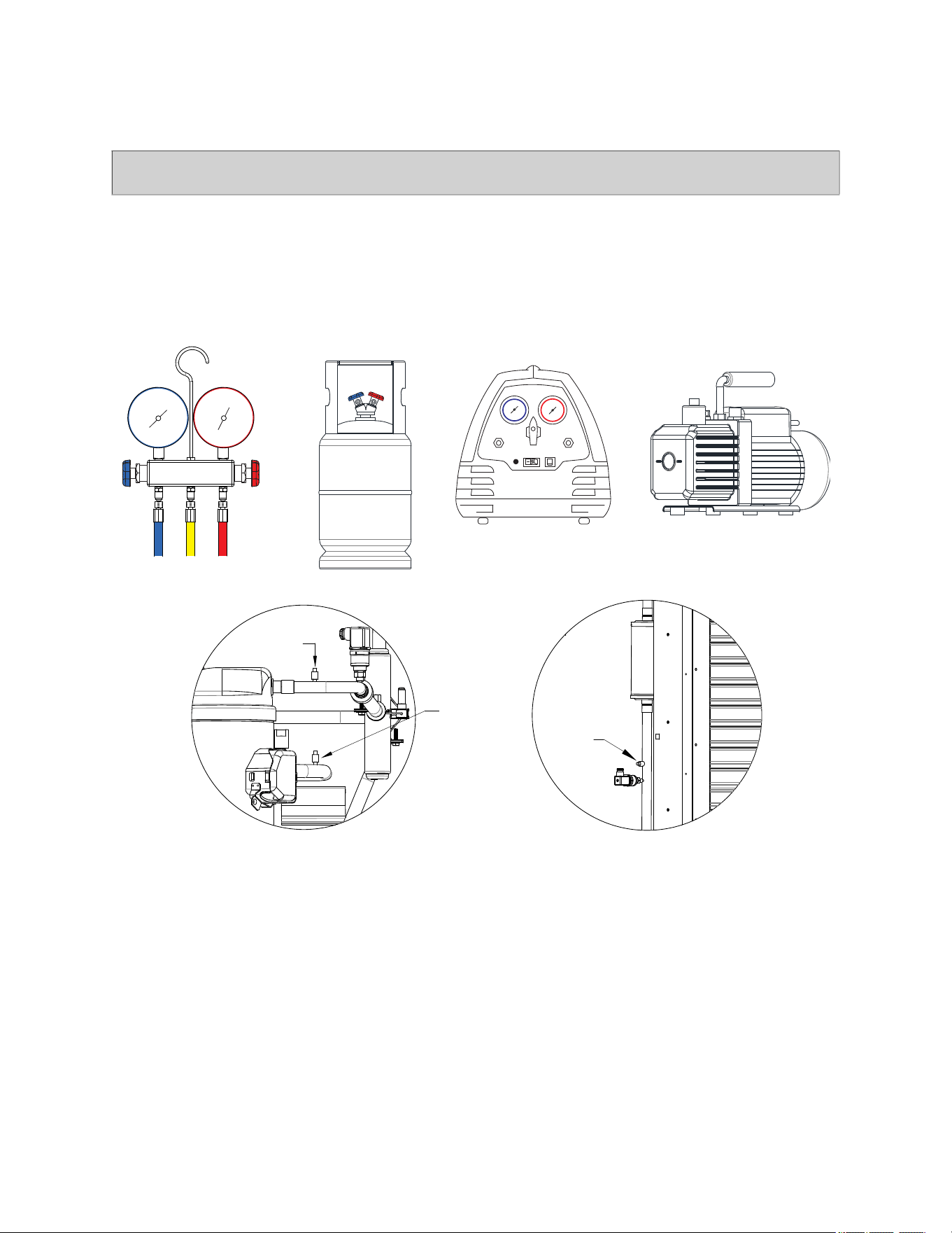
109
SERVICE INFORMATION
Basic Service
NOTE: Always wear gloves and eye protection when working with refrigerant.
NOTE: Purge lines before connecting to service ports.
Figure 57 - Refrigeration Service Tools and Service Port Locations
Monitoring the A/C System
Monitoring with HMI
The HMI can monitor the A/C temperature and pressure readings through the service function menu. Enter
HMI menu function by pressing the top two buttons simultaneously. Navigate to Service (Password 1234)
> Inputs > Refridge Diag.
The Refridge Diag menu will display the following:
WARNING: Technicians must be certified by an EPA-approved training and certification
program to service any HVAC equipment, regardless of the refrigerant.
• Discharge Pressure (DSCHRG PS)
• Discharge Condensing Temperature (DCH CON TMP)
• Suction Pressure (SUCTION PS)
• Suction Saturation Temperature (SUC SAT TMP)
• Suction Line Temp (SUC LIN TMP)
• Superheat Temperature
• EEV Position Percentage
• Compressor Hertz
• PWM Rate Percentage
• Oil Voltage - Yes/No
Red
Hose
Yellow
Hose
Blue
Hose
High Side
Service Port
Low Side
Service Port
Liquid Line
Service Port
Recovery MachineRefrigerant Recovery
Cylinder
Gauge Set
V
acuum Pump
SUCTION DISCHARGE

110
Monitoring with Gauge Set
1. Close the high side hand valve (red) and low side hand valve (blue).
2. Connect vacuum rated manifold service hoses, refer to Figure 57 on page 109.
• Red service hose to the high side service port.
• Blue service hose to the low side service port.
• Verify the yellow service hose is capped when not connected to a refrigerant tank, recovery tank, or
vacuum pump.
3. Connect a standard pressure gauge set to the service port located on the leaving side of the outdoor
coil, see Figure 57.
4. Start the system.
5. If the service hoses have a manual turn valve, open the valve. Monitor the following:
• The low side and high side gauges.
• The superheat reading should be 20°F.
6. Refer to Table 16 on page 124 to determine subcool. Compressor must be running at 100%, and
condenser fan temperature must be 110°F. Subcool should be approximately 10-20°F.
NOTE: subcool readings will vary based on ambient and condensing fan temperatures.
7. Determining the readings:
- If the readings are correct, close the gauge set and shut down the system. Disconnect the gauge
set, refer to “Removing Manifold Gauge Set” on page 113.
- If the readings are incorrect, follow the “System Troubleshooting Chart” on page 114 to locate
and repair the problem.
Recovering Refrigerant from the System
1. Connect vacuum rated manifold service hoses, refer to Figure 57 on page 109:
• Red service hose to the high side service port.
• Blue service hose to the low side service port.
• Connect the yellow service hose to the inlet port of the recovery machine.
• Connect a hose from the discharge port of the recovery machine to the recovery tank.
2. Purge all hoses of non-condensables before starting the system.
3. Place the system in ‘Evacuation Mode’. Enter HMI menu function by pressing the top two buttons
simultaneously. Navigate to Service > Test Menu > Evacuation Mode > Enable.
4. When the system is in ‘Evacuation mode’, the EEV and reheat valve (if applicable) will open and allow
full access to the system via the high and low side service ports. Ensure the compressor does not run
by pressing ‘OFF/Reset’ on the compressor VFD HMI.
5. Open the connected valve on the recovery tank.
6. Turn the recovery unit on.
7. Open the low side and high side hand valves.
8. Monitor the gauge set until all refrigerant has been recovered and the system is under a proper
vacuum.

111
Nitrogen Purging
Whenever brazing will be performed in the system, flowing nitrogen through the system is required. This
should be done when unsweating connections or brazing new components in the system. Remove
Schrader core from the inlet and outlet path for full flow and minimize back-pressure. This step is critical to
prevent oxidation and protect the system from contaminants.
Pressure Testing
Anytime repairs are made, use dry nitrogen to verify there are no leaks in the system. Connect the dry
nitrogen tank to the high and low service ports, ensuring the entire system will be pressurized. Pressurize
the system to 350-400 PSI. Use soap bubbles or another liquid leak solvent to check for leaks. Check the
system for approximately 15 minutes.
- If there are leaks, evacuate the nitrogen from the system. Repair as necessary.
- If there are no leaks, evacuate the nitrogen from the system.
For instructions on how to evacuate the system, refer to “Evacuating the System”.
Evacuating the System
1. Connect vacuum rated manifold service hoses, refer to Figure 57 on page 109:
• Red service hose to the high side service port.
• Blue service hose to the low side service port.
• Connect the yellow service hose to the vacuum pump.
2. Connect a micron gauge to the service port located on the leaving side of the outdoor coil, refer to
Figure 57.
3. Place the system in ‘Evacuation Mode’. Enter HMI menu function by pressing the top two buttons
simultaneously. Navigate to Service > Test Menu > Evacuation Mode > Enable.
4. When the system is in ‘Evacuation mode’, the EEV and reheat valve (if applicable) will open and allow
full access to the system via the high and low side service ports. Ensure the compressor does not run
by pressing ‘OFF/Reset’ on the compressor VFD HMI.
5. Open the high side hand valve (red) and low side hand valve (blue). Start the vacuum pump.
6. Pump the system down until the micron gauge reads 500 microns.
7. Close off the valve to the vacuum pump. Turn the pump off.
8. Monitor the micron gauge for twenty minutes. Make sure it does not rise above 1000 microns.
- If the reading goes above 1000 microns in less than twenty minutes, there is a leak or moisture in
the system. Determine the issue and repair.
- If the reading stays below 1000 microns, close all valves on the manifold gauge set.
9. Charge the system, refer to “Charging an Empty System” on page 112.
NOTE: To prevent trapping liquid refrigerant in the manifold gauge set, make sure the gauge set is
brought to suction pressure before disconnecting.

112
Charging an Empty System
1. Connect the manifold service hoses, refer to Figure 57 on page 109:
• Blue service hose to the liquid side service port.
• Connect the yellow service hose to refrigerant source.
2. Connect a temperature clamp near the liquid line service port located on the leaving side of the
outdoor coil, refer to Figure 57.
3. Place the system in ‘Evacuation Mode’. Enter HMI menu function by pressing the top two buttons
simultaneously. Go to Service > Test Menu > Evacuation Mode > Enable.
4. When the system is in ‘Evacuation mode’, the EEV and reheat valve (if applicable) will open and allow
full access to the system via the high side, low side, and liquid line service ports.
5. Ensure the compressor does not run by pressing ‘OFF/Reset’ on the compressor VFD HMI.
6. Open the valve on the refrigerant source.
7. Open the low side hand valve (blue) on the manifold set.
NOTE: Unit should be charged with liquid refrigerant.
8. Once the unit has at least 50% of the charge from the unit label, close the valve on the refrigerant
source and the low side hand valve (blue) on the manifold set. Abort ‘Evacuation Mode.’
9. Remove blue service hose from the liquid line service port.
10. Connect blue service hose to the low side service port. Verify the yellow service hose is connected to
the manifold and refrigerant source.
11. Open the valve on the refrigerant source.
12. Check the compressor’s oil level before starting unit. Refer to “Compressor Information” on
page 52 for compressor models and oil type information.
13. Verify the unit is in an idle state (it should not be in cooling, heating, reheat, or blower only modes).
- Occupied scheduling must be disabled. Go to Factory Settings > Occupancy Config >
Scheduling > Off.
- Turn on the cooling system through the service test menu. Go to Service > Test Menu > Test Cool/
HP > Select unit’s cooling type.
- Set the compressor to run at maximum speed and verify reheat voltage is set to 0V.
- Adjust condensing fans so that the condensing coil maintains a 110°F liquid saturation temperature.
14. To prevent damage to the compressor, do not open the hand valve all the way. Crack open the low
side hand valve (blue) on the manifold set.
15. Continue charging the system until the following conditions are met:
- Refer to Table 16 on page 124 to determine subcool.
- Compressor must be running at 100%, and condenser fan temperature must be 110°F.
- Subcool should be approximately 10-20°F. NOTE: subcool readings will vary based on ambient
and condensing fan temperatures.
- The superheat reading should be 20°F.
16. Close the low side hand valve (blue). Monitor the gauge set, and determine if the system is operating
properly.
NOTE: Once the unit is back to full operation, verify any altered settings (i.e. Scheduling) are
changed back to their last set configuration.

113
Charging System Low on Refrigerant
1. To add refrigerant with system running, open the low side hand valve (blue).
2. Start the unit. Verify the unit is in an idle state (it should not be in cooling, heating, reheat, or blower
only modes). Occupied scheduling must be disabled.
3. Navigate to Service > Test Menu > State > Cool/HP to activate system test. Once the test is active,
you may monitor and adjust settings.
• Set the compressor to run at maximum speed.
• Adjust condensing fans, and monitor the condensing coil maintains a 110°F temperature.
• Verify reheat voltage is set to 0V.
4. Monitor the system until the following conditions are met:
- Refer to Table 16 on page 124 to determine subcool.
- Compressor must be running at 100%, and condenser fan temperature must be 110°F.
- Subcool should be approximately 10-20°F. NOTE: Subcool readings will vary based on ambient
and condensing fan temperatures.
- The superheat reading should be 20°F.
5. Check compressor oil level after a repair. Refer to “Compressor Information” on page 52 for
compressor models and oil type information.
Removing Manifold Gauge Set
1. Make sure the hand valves are closed.
2. Make sure the refrigerant source is closed / the vacuum pump is not running.
3. Disconnect all hoses from the service valve ports.
4. Install the service port caps. Tighten by hand.
114
Troubleshooting
The following tables and information list possible causes and corrective actions for possible problems.
Review this section prior to consulting technical support.
System Troubleshooting Chart
Problem Potential Cause Corrective Action
Unit will not start Power failure
Check voltage to the unit.
Check the disconnect switch.
Check the circuit breaker.
Check the hot, neutral, and ground wiring.
Unit On - HMI Off Power Issue
Check connector J13 is properly connected.
Check wiring from HMI to connector J13.
Verify the circuit breaker (CB-01) is On.
System operates continuously -
poor cooling/heating
(heat pump mode)
Shortage of refrigerant Test for leaks. Add refrigerant.
Restricted discharge line Repair or replace as required.
Dirty or clogged filters Inspect filters. Clean or replace.
Dirty indoor coil
Inspect coil. Clean the coil, refer to “Coil
Cleaning Procedure” on page 139.
Low airflow across indoor
coil
Check blower speed, duct static pressure,
filters.
Compressor
Verify compressor modulates between Min to
Max frequency.
Electronic Expansion
Valve (EEV)
Verify EEV position is 0% when not in
heating or cooling under Refridge Diag. See
“Monitoring the A/C System” on page 109.
Check the correct EEV is installed.
Refer to “Electronic Expansion Valve
(EEV-1)” on page 135.
System operates – blows cold
air in heat pump mode
Compressor
Verify compressor modulates between Min to
Max frequency.
Incorrect refrigerant
Refer to “Superheat and Subcooling” on
page 124 to check parameters.
Non-condensable in
system
Recover the charge, evacuate the system.
Recharge the system. Refer to “Basic
Service” on page 109.
Faulty reversing valve Test reversing valve.
Defrost control Test defrost control.
System operates - blows cold
air in gas heat mode
Gas supply issue
Refer to “Furnace Troubleshooting Chart”
on page 123.
Faulty gas train
components.
System runs – blows cold air in
electric heat mode
Improper wiring Check electrical wiring.
Electric disconnect switch Check electric heater disconnect switch
Fuse in electric heater
panel
Check fuses, replace is required.
Airflow Switch
Check airflow switch and tubing at the MUA
board.
115
HMI Fault Codes
Problem Potential Cause Corrective Action
Fire There is an input from the fire detector.
Check wiring. Repair broken or loose
wiring connections.
Replace fire detector.
Smoke (optional)
There is an input from the smoke
detector.
Verify the smoke detector is set up
properly.
Check wiring. Repair broken or loose
wiring connections.
Replace smoke detector.
Gas PS High
(optional)
The board is receiving an input on the
gas pressure high terminal.
Adjust regulator or add regulator.
Check wiring. Repair broken or loose
wiring connections.
Replace switch.
Refer to “High Gas Pressure Switch
(PS-03)” on page 130.
Gas PS Low
(optional)
The board lost input on the gas pressure
low terminal. There should be an input
when gas pressure is at the proper level.
Low gas pressure switch.
Check wiring. Repair broken or loose
wiring connections.
Replace switch.
Refer to “Low Gas Pressure Switch
(PS-04)” on page 130.
Supply Overload
Exhaust Overload
Motor overload has tripped.
Check motor for debris.
Check contactor/motor wiring
connections.
Check overload reset button.
Check overload amperage setting.
Check motor bearings.
Stat Missing
(Return, Outside,
Intake, Discharge,
Space, Coil)
If the temperature sensor signal being
sensed is too low, a missing fault will be
active.
Install and wire sensor.
Check for faulty wiring, refer to
“Temperature Sensor” on page 129.
Stat Broken (Return,
Outside, Intake,
Discharge, Space,
Coil)
If the temperature sensor signal being
sensed is too high, a broken fault will be
active.
Install and wire sensor.
Check for faulty wiring, refer to
“Temperature Sensor” on page 129.
Space HMI Missing
One of the HMIs in the system is not
connected properly, or one of the settings
is not properly set.
Verify that the “# of HMIs” is set correctly.
Verify there is no damage to the HMI(s).
Check for loose or damaged wiring to
HMI(s).
If space temperature is being utilized,
make sure “HMI Averaging” is set to ‘On’
for all space HMIs.
RTC 1 Temp Sensor
Real-Time Clock (RTC) temperature
sensor located on MUA board.
Verify there is no damage to the MUA
board or the wiring to the MUA board.
116
Airflow
Signal was not received from air switch
when supply blower was running.
Verify supply fan operation, refer to
“Start-Up Procedure” on page 82.
Check damper operation.
Check airflow switch and tubing at the
MUA board.
FSC1 High Temp
The Flame Safety Controller (FSC)
continually and safely monitors, analyze,
and controls the proper operation of the
gas burner and inducer motor.
Check connector J7 on the MUA board.
Make sure the connection is secure.
High limit switch failed open. There
should be continuity.
FSC1 Rollout
If flame-rollout is present, the switch de-
energizes heater circuit on individual
furnace. Must be manually reset by
pressing the small button on the switch.
Check wiring to the switches.
Reset the switch.
Rollout switch failed open. There should
be continuity.
Check for a blocked tube, low airflow, or
low gas pressure.
FSC Vent Proving
The FSC verifies that airflow is sensed by
the induced draft air sensor.
Kinked/blocked/damaged hose.
Blockage in vent system. Poor venting.
Check bleed hole in proving switch.
Clogged condensation drain.
Power vent motor.
Failed vent proving switch.
Refer to “Vent Proving Switch (PS-01)”
on page 131.
Min Low Pressure
Limit
The suction pressure for the compressor
is below the minimum threshold in
software.
Follow possible checks for “Refrigerant
Low PS.”
Refrigerant Low PS
If the system is operating at a low
pressure and temperature range, the
system can become inoperable.
Verify low pressure switch operation.
Low Refrigerant. Refer to “Monitoring
the A/C System” on page 109.
Refrigerant High PS
If the system is operating at a high
pressure and temperature range, the
system can become inoperable.
Verify high pressure switch operation.
Faulty condensing fan motor.
Outside coil plugged.
Inadequate airflow across coil.
Blockage in the system. Refer to
“Monitoring the A/C System” on
page 109.
Refrigerant
DSCHRG Temp
(Heat Pump)
Discharge temperature is out of range.
Follow possible checks for “Refrigerant
High PS”.
Problem Potential Cause Corrective Action

117
Oil Sensor
The oil level sensor monitors the
compressor’s internal oil level. Refer to
“Compressor Information” on
page 52.
Low oil level, if sight glass is available,
check level.
Oil depositing itself in pipes. Increase
compressor velocity for short periods of
time.
Refer to “Superheat and Subcooling”
on page 124 to check parameters.
Check oil level sensor wiring.
Check transformer voltages.
Oil level sensor failure, refer to “Oil
Level Sensor (Sen-1)” on page 131.
Envelope Cond
Temp High
Indoor and outdoor coil operating
temperatures are too high.
Follow possible checks for “Refrigerant
High PS”.
Refer to “Superheat and Subcooling”
on page 124 to check parameters.
Envelope Cond
Temp Low
Indoor and outdoor coil operating
temperatures are too low.
Follow possible checks for “Refrigerant
Low PS”.
Refer to “Superheat and Subcooling”
on page 124 to check parameters.
Envelope Angle
Indoor and outdoor coil operating
temperatures are out of range.
Follow possible checks for “Refrigerant
low PS” and “Refrigerant high PS”
Refer to “Superheat and Subcooling”
on page 124 to check parameters.
Max Head Pressure
The max head pressure for the
compressor is too high.
Refer to “Monitoring the A/C System”
on page 109.
Check airflow.
Freezestat lockout
(optional)
The discharge temperature was too low
for a long period of time.
Check gas pressure.
Check for proper burner firing.
Use the HMI to reset.
Overheat Stat
lockout (optional)
The discharge temperature was too high
for a long period of time.
Check cooling system.
Use the HMI to reset.
Firestat lockout
(optional)
Intake or discharge temperatures
exceeded the firestat set point.
Use the HMI to reset.
Check for bad regulators, or modulating
valves.
Suction PS
MUA Board has detected a pressure
sensor failure.
Verify suction pressure transducer is
operating correctly and wired properly.
Temp Sens
MUA Board has detected a temperature
sensor failure.
Verify suction line temp sensor is
operating correctly and wired properly.
Check EEV, refer to “Electronic
Expansion Valve (EEV-1)” on
page 135.
DX/Condensation
Float Detect
Input signal from the drain pan float
switch.
Make sure the pan drain is clear and
water is draining.
Check for shorted wires.
Replace float switch.
Modbus System
Communication
Software mismatch.
Verify P410 (Modbus Address) is 21 on
VFD.
Problem Potential Cause Corrective Action
118
Supply VFD Comm Modbus communication fault.
Check Modbus wiring and connections.
Verify Modbus address.
Verify Min and Max settings of the VFD to
the MUA board settings. Go to Factory
Settings > Unit Options > Blower
Config > VFD Freq Limits.
Master ROM CRC Software mismatch. Contact technical support.
Clogged Filters
(optional)
Input from filter airflow switch.
Clean or replace filters.
Refer to “Clogged Filter Switch (PS-
10)” on page 126.
Compressor Comm Communication Error.
Check wiring from Compressor VFD to
compressor.
Furnace Float
Input signal from the furnace
condensation float switch is active.
Refer to “Furnace Condensation
Drain” on page 17 to check float.
Verify pipe connections are not clogged.
Verify the pipes are draining.
Check for shorted wires.
Replace float switch.
Electric Heater Fault
Voltage input is lost while the electric
heater is active.
Check electric heater wiring to board
connector J7 pin 10.
Verify all other wiring is connected
properly.
Check Fuse(s).
RH Sensor (Space,
Intake, Discharge)
One of the Relative Humidity (RH)
sensors are not working.
Refer to “Humidity/Temperature
Sensors” on page 128.
HMI “x” Revision
Wrong
Software mismatch.
Contact technical support to flash the
appropriate software.
HMI Config Error
HMI is not connected, or HMI is assigned
incorrectly.
Install HMI or change HMI address using
bottom 2 buttons on HMI. Refer to
“Configuring HMI” on page 57.
Compressor VFD
Off
Compressor controller is set in the Off or
Hand On position.
Verify that the compressor controller is
set to the Auto On position.
DF Faults
DF faults are communicated from the
compressor drive to the HMI.
Refer to “Compressor Drive VFD
Troubleshooting Chart” on page 119.
Problem Potential Cause Corrective Action
119
Compressor Drive VFD Troubleshooting Chart
Problem Potential Cause Corrective Action
Earth Fault
There is current from the output
phases to ground (earth) in the
cables, or the motor.
Check the cables from the converter to the compressor.
Check for continuity from the compressor terminals to
ground. There should be no continuity.
Control Word
Timeout
There is no communication to
the frequency converter. Only
active if setting 8-04 is NOT set
to [0] OFF.
Verify wiring, and connections are correct.
Check cable connections to the converter.
Increase the Control Word Timeout time setting 8-03.
Check the communication components.
Over Current
This fault can be caused by
shock loading, or quick
acceleration with high inertia
load.
Make sure the unit is OFF. Verify the motor shaft can
be turned.
Check the motor size matches the frequency converter.
Check parameters 1-20 to 1-25 for correct setup.
Torque Limit
The torque has exceeded the
value in setting 4-16 or 4-17.
Check for excessive current draw on the motor.
If the motor torque limit is exceeded during ramp-up,
extend ramp up time.
If the generator torque limit is exceeded during ramp
down, extend ramp downtime.
If torque limit occurs while running, increase the torque
limit. Verify the system operation can operate safely at
a higher torque.
Inverter
Overload
The converter is about to cut
out because of an overload.
The thermal protection issues a
warning at 98% and an alarm at
100%. This converter cannot be
reset until the counter is at 90%.
Compare current output from LCP to the converter’s
rated current.
Compare the output shown from the LCP with
measured motor current.
Verify the drive load on the LCP. Monitor the value. The
counter will increase when running above the
continuous current rating. The counter will decrease
when running below the continuous current rating.
DC Under Volt
If the intermediate circuit
voltage drops below the under-
voltage limit, the frequency
converter checks if a 24V DC
backup supply is connected. If
no 24V DC backup supply is
connected, the converter trips
after a fixed time delay. The
time delay varies with unit size.
Check that the supply voltage matches the frequency
converter voltage.
Perform input voltage test.
DC Over Volt
If the intermediate circuit
voltage exceeds the limit, the
converter trips after a time.
Connect a brake resistor.
Extend the ramp time.
Change the ramp type.
Activate the functions in 2-10 Brake Function.
Increase 14-26 Trip Delay at Inverter Fault.
If the alarm/warning occurs during a power sag, the
solution is to use kinetic back-up (14-10 Mains Failure).
Short Circuit
There is short-circuiting in the
motor or motor wiring.
Remove power to the frequency converter and repair
the short circuit.
120
Mains Phase
Loss
A phase is missing on the
supply side, or the mains
voltage imbalance is too high.
This message also appears for
a fault in the input rectifier on
the frequency converter.
Options are programmed at
parameter 14-12.
Check the supply voltage and supply currents to the
frequency converter.
Refer to “Compressor Drive Input/Output (VFD-02)”
on page 128.
U Phase Loss
The “U” output terminal signal is
lost.
Refer to “Compressor Drive Input/Output (VFD-02)”
on page 128.
V Phase Loss
The “V” output terminal signal is
lost.
W Phase Loss
The “W” output terminal signal
is lost.
24V Supply
Low
The 24V DC is measured on the
control card. The external
24V DC backup power supply
maybe overloaded.
Check wiring.
Check backup supply.
Mains Fail
This warning/alarm is only
active if the supply voltage to
the frequency converter is lost
and parameter 14-10 is NOT
set to [0] No Function.
Check the fuses to the frequency converter and mains
power supply to the unit.
Safe Stop
Loss of the 24V DC signal on
terminal 37 has caused the filter
to trip.
Apply 24V DC to terminal 37 and reset the filter.
Start Fail
The speed has not been able to
exceed parameter 1-77 during
start within the allowed time.
Motor may be locked.
Speed Limit
When the speed is not within
the specified range in
parameters 4-11 and 4-13, the
converter shows a warning.
When the speed is below the
specified limit in parameter 1-86
(except when starting or
stopping), the frequency
converter will trip.
This alarm is reset automatically, and the compressor
restarts automatically.
Current Limit
The current is higher than the
value in 4-18 Current Limit.
Ensure that the motor data in
parameters 1-20 to 1-25 are set
correctly. Possibly increase the
current limit. Be sure that the
system can operate safely at a
higher limit.
Make sure that motor data in parameters 1-20 to 1-25
are set correctly.
Possibly increase the current limit. Be sure that the
system can operate safely at a higher limit.
Problem Potential Cause Corrective Action
121
Compressor Troubleshooting Chart
Problem Potential Cause Corrective Action
Compressor
will not start
Shorted or broken wires Use a multi-meter to check the compressor wiring
harness for an open or short circuit.
Locked rotor Check continuity of the compressor. Replace if failed.
Low voltage Test voltage.
Internal failure If no other failure is present, there is an internal failure.
Replace the compressor.
Compressor
runs
intermittently
Shorted or broken wires Check the compressor wiring harness for an open or
short circuit.
Loose connections Secure connections.
Shorted or grounded compressor
Check for continuity from the compressor terminals to
ground.
There should be no continuity.
Overcharge of refrigerant Recover part of the refrigerant.
Dirty outdoor coil Clean the outdoor coil.
Incorrect thermostat location Relocate thermostat.
Electronic Expansion Valve (EEV) Verify the correct expansion valve is installed.
Hot Gas Reheat Valve Refer to “Hot Gas Reheat Valve (HG-1/HG-2)” on
page 135.
Faulty reversing valve Test reversing valve.
Defrost control Test defrost control.
Compressor
cycles on
overload
Shortage of refrigerant Test for leak. Recharge.
Restricted discharge line Repair or replace as needed.
Non-condensables in system Recover the charge, evacuate the system. Recharge
the system.
Recirculation of condensing air Remove airflow obstruction.
Electronic Expansion Valve (EEV) Make sure the expansion valve is operating properly.
Compressor
making
abnormal
noise
Overcharge of refrigerant Recover part of the refrigerant.
Loose hardware Tighten the mounting bolts.
Internal failure If no other failure is present, replace the compressor.
Liquid in compressor head Check “Superheat and Subcooling” on page 124
and EEV position.
Low suction
pressure
Low charge Check “Superheat and Subcooling” on page 124.
Restricted discharge line, drier, or
reversing valve
Repair as needed.
Compressor
oil issues
Low oil If sight glass is available, check oil level. Add oil.
If there is an oil level sensor. Refer to “Oil Level
Sensor (Sen-1)” on page 131.
Imbalance of refrigerant Check “Superheat and Subcooling” on page 124.
Compressor running too slow for a
long period of time
Adjust compressor speed.
122
Airflow Troubleshooting Chart
Problem Potential Cause Corrective Action
Fan Inoperative
Blown fuse/Open circuit breaker
Replace fuse or reset circuit breaker and
check amps.
Disconnect switch in “Off” position Turn to “On” position.
Door switch
Verify door is closed properly.
Check door switch wiring and switch.
Motor wired incorrectly
Check motor wiring to wiring diagram located
on fan motor.
Motor starter overloaded Reset starter and check amps.
HMI set to “Blower Off” Set HMI to “Blower On.”
Motor Overload
Fan rotating in the wrong direction
Verify fan is rotating in the direction shown on
rotation label.
Fan speed is too high Reduce fan RPM.
Motor wired incorrectly
Check motor wiring to wiring diagram located
on fan motor.
Check the fan wiring.
Check fan rotation using the HMI.
Overload in starter set too low Set overload to motor FLA value.
Motor HP too low Determine if HP is sufficient for job.
Duct static pressure lower than design Reduce fan RPM.
Insufficient Airflow
Fan rotating in the wrong direction
Verify fan is rotating in the direction shown on
rotation label.
Check the fan wiring.
Check fan rotation using the HMI.
Poor outlet conditions
There should be a straight clear duct at the
outlet.
Intake damper not fully open
Inspect damper linkage and replace damper
motor if needed.
Duct static pressure higher than design
Improve ductwork to eliminate or reduce duct
losses.
Fan speed too low Increase fan RPM. Do not overload motor.
Indoor coil dirty or frozen Clean Indoor Coil and filters.
Supply grills or registers closed Open and adjust.
Dirty or clogged filters Clean and/or replace.
Excessive Airflow
Fan speed to high Reduce fan RPM.
Filters not installed Install filters.
Duct static pressure lower than design Reduce fan RPM.
Excessive Vibration and
Noise
Fan speed is too high Reduce fan RPM.
Damaged or unbalanced wheel Replace wheel.
Fan is operating in the unstable region of
the fan curve
Refer to performance curve for fan.
Bearings need lubrication or replacement Lubricate or replace.
123
Furnace Troubleshooting Chart
Problem Potential Cause Corrective Action
Furnace Does Not
Light/Stay Lit
Main gas is off Open main gas valve.
Shut off valve closed Open shut off valve.
ON/OFF gas valve is off Turn ON/OFF gas valve on.
Gas pressure out of range Adjust to proper gas pressure.
Air in gas line Purge gas line.
Dirt in burner orifices Clean orifices with compressed air.
Spark igniter rod out of position Relocate spark igniter rod to proper area.
No spark at igniter Refer to “Flame Safety Control (FSC-01)” on page 133.
Defective flame safety controller
Excessive drafts Re-direct draft away from unit.
Safety device has cut power Check limits.
Check airflow switch and tubing at the MUA board.
Dirty flame sensor Clean flame sensor.
Defective flame sensor Change heating set-points to call for heat.
Defective valve Refer to “Gas Valves” on page 132.
Loose gas valve wiring
Thermostat not calling for heat Change heating set-points to call for heat.
Unit cycling on high limit Check gas pressure. Increase airflow through furnace, if
required.
Not Enough Heat Main gas pressure too low Increase main gas pressure – do not exceed 14 in. wc inlet
pressure.
Unit locked into low fire Check wiring or modulating valve settings. Refer to
“Furnace Start-Up Summary” on page 83.
Too much airflow Decrease airflow if possible.
Furnace undersized Check design conditions.
Gas controls not wired properly Refer to “Gas Valves” on page 132.
Thermostat setting too low Increase thermostat setting.
Thermostat malfunction Check thermostat.
Too Much Heat Defective modulating gas valve Check/replace modulating valve.
Thermostat setting too high Decrease thermostat setting.
Unit locked into high fire Check modulation valve settings. Refer to “Furnace Start-
Up Summary” on page 83.
Thermostat wired incorrectly Check thermostat wiring.
Too much primary air Reduce primary air.
Manifold pressure set too high Reduce manifold pressure.
Lifting Flames or
Flashback
Dirty orifice Check and clean orifice.
Orifice too large Check orifice size.
Insufficient primary air Increase primary air.
Yellow Tipping Flames Misaligned orifice Check manifold alignment.
Insufficient primary air Increase primary air.
Orifice too large Check orifice size.
Floating Flames or
Flame Rollout
Manifold pressure too high Decrease manifold pressure.
Blocked vent Check venting system.
Misaligned orifice Check manifold alignment.
124
Superheat and Subcooling
When determining superheat, use Table 16 to convert the low side pressure gauge (suction line) to the
appropriate temperature. Subtract the converted temperature from the suction line surface temperature.
There should be approximately a 20°F difference. Superheat monitors what state the refrigerant is when it
leaves the evaporator coil. High superheat indicates the refrigerant has picked up more heat than
designed. Low superheat indicates the refrigerant has not picked up enough heat and can cause flooding
in the compressor. If superheat is incorrect, verify subcool first before making changes to the system.
When determining subcool, convert the high side pressure gauge (condensing coil liquid line) to the
appropriate temperature. Subtract the converted temperature from the liquid line surface temperature.
There should be approximately a 10-20°F difference. Subcooling monitors what state the refrigerant is
when it leaves the condensing coil. High subcooling means the condenser is flooded. Low subcooling
means the condenser is starving.
• If the superheat is high and the subcool is low under normal operating conditions, the system may be
low on charge. Determine the cause of low refrigerant and repair as necessary. Refer to “Charging
System Low on Refrigerant” on page 113.
• If the superheat is low and the subcool is high under normal operating conditions, the system may be
overcharged. Refer to “Recovering Refrigerant from the System” on page 110.
• If the superheat is high and the subcool is high under normal operating conditions, there could be a
blockage in the coil, or line set.
NOTE: Ambient temperatures may affect subcooling.
Table 16 - R410A Pressure Temperature
Temperature (°F) Refrigerant Pressure Temperature (°F) Refrigerant Pressure
-45 7.7 55 156.6
-40 10.8 60 170.7
-35 14.1 65 185.8
-30 17.8 70 201.8
-25 21.9 75 218.7
-20 26.3 80 236.5
-15 31.2 85 255.4
-10 36.5 90 275.4
-5 42.2 95 296.4
0 48.2 100 318.6
5 55 105 341.9
10 62.3 110 366.4
15 70.2 115 392.3
20 78.7 120 419.4
25 87.8 125 447.9
30 97.5 130 447.9
35 107.9 135 509.4
40 118.9 140 542.5
45 130.7 145 577.3
50 143.3 150 613.9
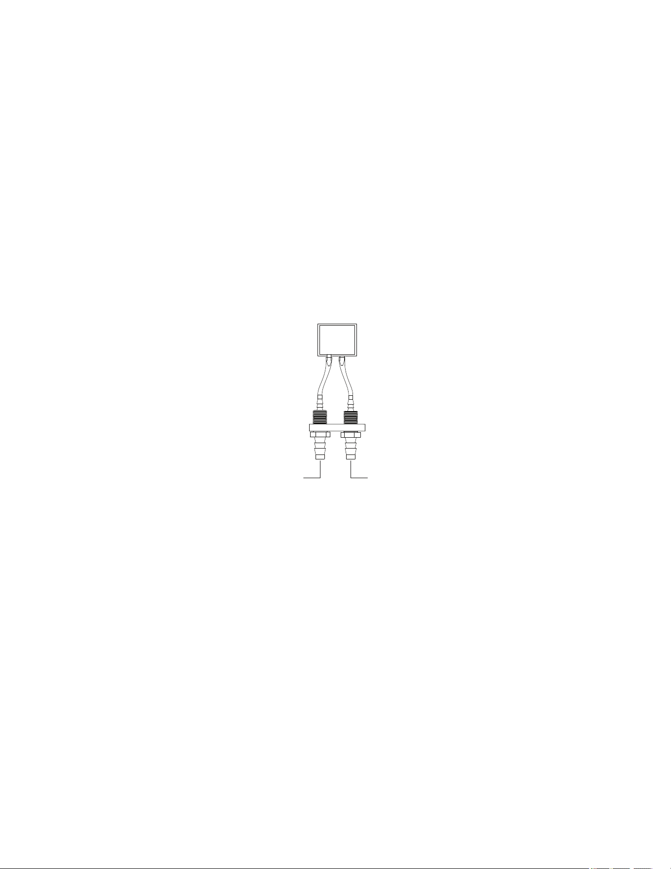
125
Component Check/Testing
On-board Airflow Sensor
1. Verify the tubing to the on-board sensor is connected. Confirm there are no kinks, cracks, or damage
to the tubing. Replace tubing if needed.
2. With the unit ON, set the blower to “Manual” through the HMI. Go to Factory Settings > Unit Options
> Blower Config > Blower Control > Manual.
3. Use the HMI to modulate the blower speed to achieve system’s minimum design CFM. Go to User
Settings > Fan Speed to adjust blower frequency or percentage.
4. Monitor the static pressure on the HMI through the service menu for at least one minute. Go to Service
> Variable Values > Inputs > Onbd PS.
5. Record the lowest pressure reading.
6. Set the “PS Set Point” to 0.05” w.c. below the lowest static pressure reading that is observed. Go to
Factory Settings > Unit Options > Blower Config > Airflow Proving > PS Set Point.
Example: If the lowest pressure reading observed is 0.20” w.c., set the “PS Set Point” to 0.15” w.c.
Figure 58 - Board Airflow Sensor
H1 L2
PS1
Low Pressure
Tubing
High Pressure
Tubing
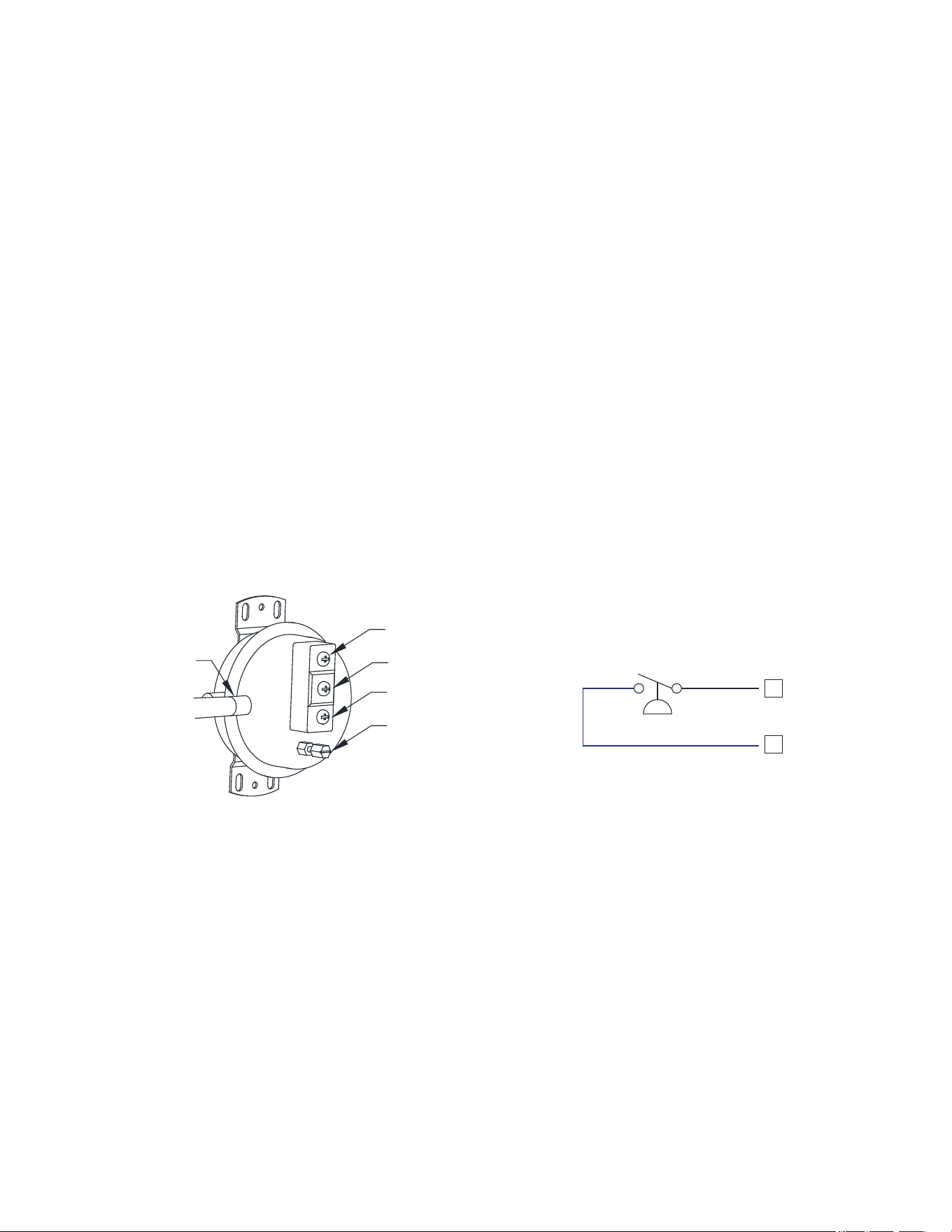
126
Clogged Filter Switch (PS-10)
1. The vent tube should be connected to the low side port (Figure 59). A fault will occur when the switch
senses a negative pressure.
2. If the “Clogged Filters” fault is active:
• Check the filters. If the filters are clogged or damaged, replace as needed. Check for any other
obstructions in the unit.
• Verify the electrical connections are secure and tight. Verify vent tube is not pinched or damaged.
• When the unit is powered ON:
- There should be 24-28V AC at connector J13 pin 5 to ground. If the voltage reading is incorrect,
check the wiring harness and voltage at the circuit board.
- There should be 0V AC at connector J13 pin 12 to ground. If there is voltage at pin 12, check the
adjustment of the switch.
Clogged Filter Switch Field Adjustment
Follow these steps if performing a part replacement, or to calibrate the switch.
• Install the switch. Install the vent tube on the low side port.
• Install the electrical connections. Power the unit ON. Set dampers to 100% open for outdoor air.
Monitor the HMI screen.
• Use a screwdriver to turn the adjustment screw clockwise until it is completely seated in the switch.
Use material suitable to block 50-75% of the intake from the outside of the unit.
Turn the adjustment screw counter-clockwise in one turn increments (waiting 3 seconds per adjustment)
until the “Clogged Filters” fault is active. Turn the adjustment screw a 1/4 to 1/2 turn clockwise until the fault
is no longer active.
Figure 59 - Clogged Filter Switch
Low Side
(Front)
Adjustment Screw
Normally Open
Common
Normally Closed
J13
5
12
NO C
PS-10
BR
PR
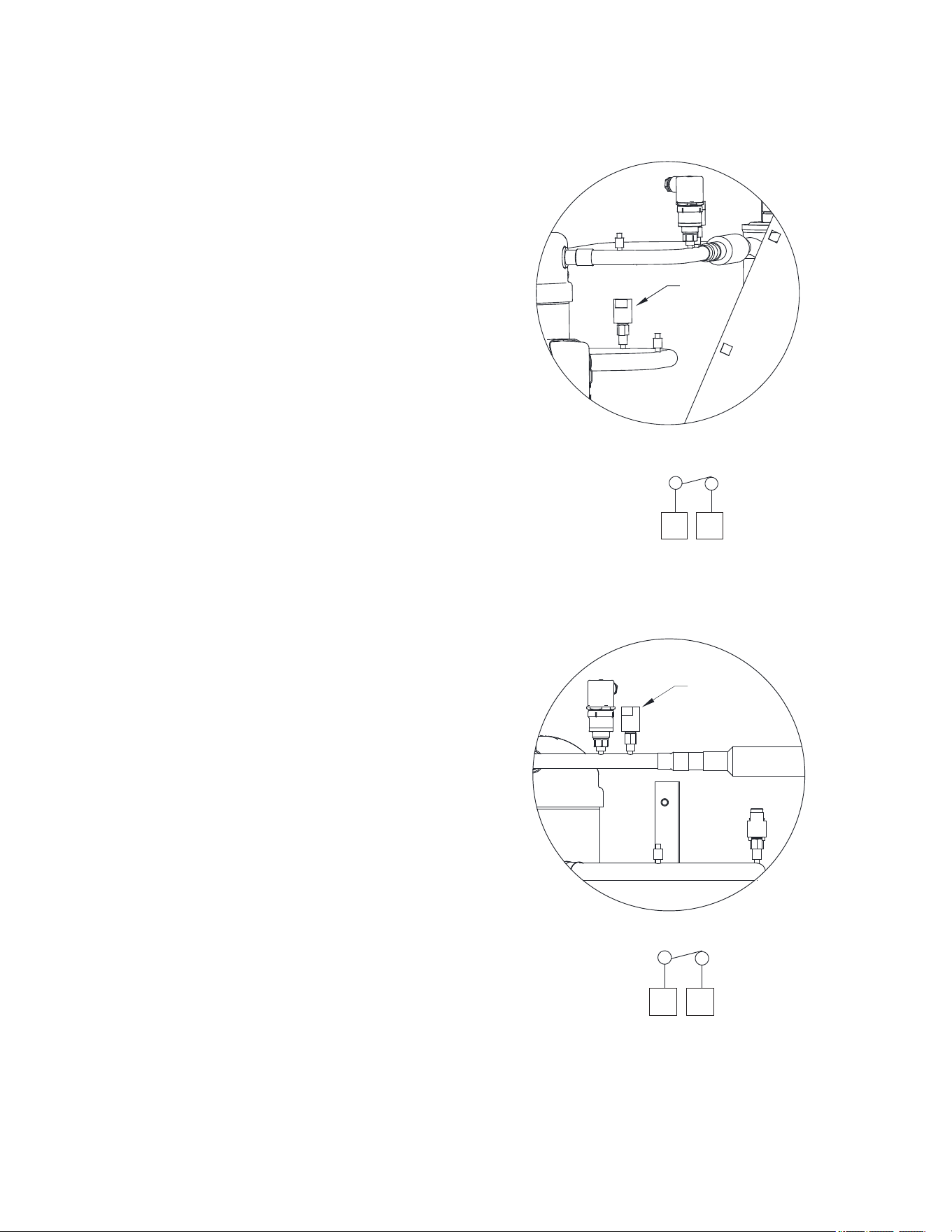
127
Low Refrigeration Pressure Switch (SW-15)
Figure 60 - Low Refrigeration Pressure Switch
1. For the low pressure switch (Figure 60), insert a
back probe tool at connector J36 pin 1 and pin 2.
Power the unit ON. Check for voltage at the following
pins:
• J36 pin 1 to ground. There should be 24-28V AC.
• J36 pin 2 to ground. There should be 24-28V AC.
- If the voltage is incorrect, continue to step 2.
- If the voltage is correct, the system may need to be
charged. Refer to “Monitoring the A/C System”
on page 109.
2. Check the electrical circuit. Power the unit OFF.
Check for continuity in the wiring harness.
• J36 pin 1 to pin 2. There should be continuity.
• J36 pin 1 to ground. There should be no continuity.
• J36 pin 2 to ground. There should be no continuity.
- If any of the continuity readings are incorrect, verify
the wiring is not damaged. If no damage is found,
replace the low pressure switch.
- If all of the continuity readings are correct, there
may be an issue with transformer.
High Refrigeration Pressure Switch (SW-16)
Figure 61 - High Refrigeration Pressure Switch
1. If a high pressure switch (Figure 61) failure
occurred, manually reset the switch.
2. For the high pressure switch, insert a back probe
tool at connector J36 pin 3 and pin 4. Power the unit
ON. Check for voltage at the following pins:
• J36 pin 3 to ground. There should be 24-28V AC.
• J36 pin 4 to ground. There should be 24-28V AC.
- If the voltage is incorrect, continue to step 3.
- If the voltage is correct, the system maybe
overcharged. Refer to “Monitoring the A/C
System” on page 109.
3. Check the electrical circuit. Power the unit OFF.
Check for continuity in the wiring harness.
• J36 pin 3 to pin 4. There should be continuity.
• J36 pin 3 to ground. There should be no continuity.
• J36 pin 4 to ground. There should be no continuity.
- If any of the continuity readings are incorrect,
verify the wiring is not damaged. If no damage is
found, replace the high pressure switch.
- If all of the continuity readings are correct, there
may be an issue with transformer.
SW-15
SW-15
BK
J36
1
2
BK
SW-16
SW-16
BK
J36
3
4
BK
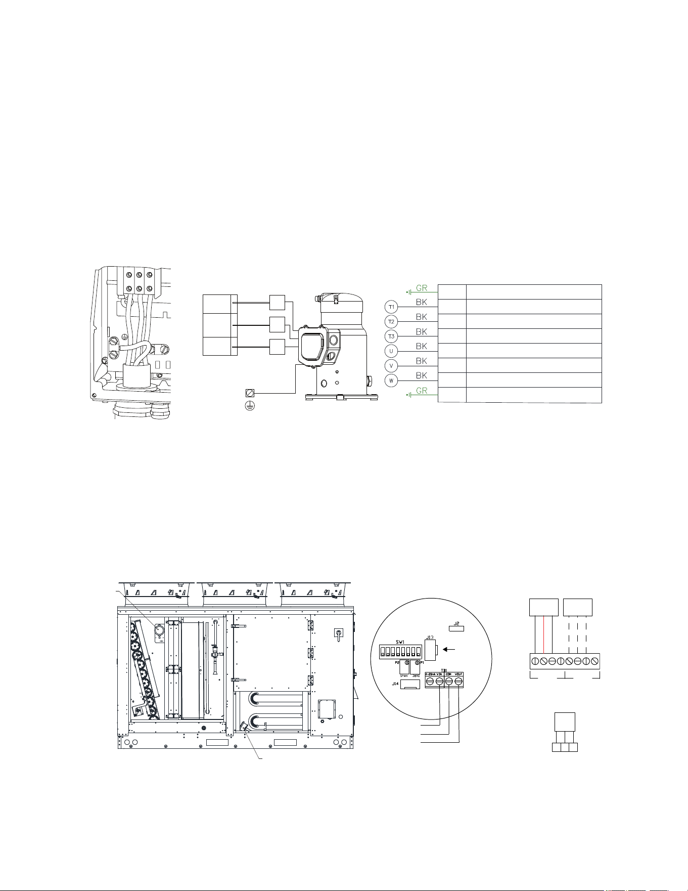
128
Compressor Drive Input/Output (VFD-02)
1. Power the unit OFF. Verify there is no damage to the wiring. Make sure all connections are secure and
connected. Verify wiring connections to the schematic. Refer to Figure 62 for details.
2. Verify the unit is OFF. Check for open or short circuits in the wiring harness.
3. Power the unit ON. Check for voltage at the following terminals:
• Terminal L1 to ground. Verify reading to nameplate voltage.
• Terminal L2 to ground. Verify reading to nameplate voltage.
• Terminal L3 to ground. Verify reading to nameplate voltage.
• Terminal T1/U to ground. Voltage will vary with compressor speed.
• Terminal T2/V to ground. Voltage will vary with compressor speed.
• Terminal T3/W to ground. Voltage will vary with compressor speed.
Figure 62 - Compressor Drive
Humidity Temperature Sensor
Intake (HUM-1)/Space (HUM-2)/Discharge (HUM-3)
Refer to Figure 63 for component locations. Check the following:
1. Verify the wiring is connected properly to the terminal block.
2. Verify the DIP switches are set properly. Make sure switch 7 and 8 are ON.
3. Check the wiring is connected properly at the switch.
4. Make sure all the connections are clean, and that there is no condensation on the RH sensor circuit
board.
Figure 63 - Humidity/Temperature Sensors
T3 (98) Compressor
3 Phase Input
or Single Phase Input
3 Phase Input
Compressor
Compressor
3 Phase Input
or Single Phase Input
T1 (96)
T2 (97)
L1 (91)
L3 (93)
L2 (92)
95 Input Ground
99 Compressor Ground
95
91
L1
92
L2
93
L3
T1
T2
T3
96 U
97 V
98 W
99
CDS 302
HUM-1
HUM-3
1
3
4
2
765 8
ON
Sensor
Plug
BK
WH
RD
AI-3
AI-2
J14
18
24VDC
0-10V IN
COMMON
HUM-1
VIN
VOUT
COM
RD
BK
WH
INTAKE
HUM-2
COMMON
0-10V IN
24VDC
VIN
VOUT
COM
SPACE
789
J31
HUM-3
COM
VOUT
VIN
BK
RD
SHD
DISCH
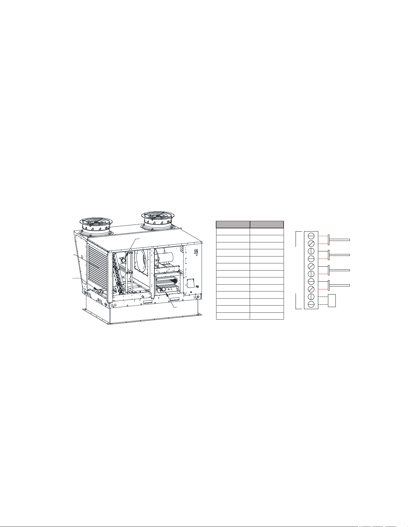
129
Temperature Sensor
Intake (SN-01)/Return (SN-02)/Outdoor (SN-03)/Discharge (SN-04)/Space (HUM-2)
Refer to Figure 64 component locations. Check the following:
1. Make sure the unit is OFF.
2. Make sure the wires are connected properly.
3. Measure the resistance of the temperature sensor. Use the temperature/ohm chart to determine your
readings.
• SN-01 – J15 pin 1 to pin 2
• SN-02 – J15 pin 3 to pin 4
• SN-03 – J15 pin 5 to pin 6
• SN-04 – J15 pin 7 to pin 8
• HUM-2 – J15 pin 9 to pin 10
- If there is 0 ohms, the sensor or wires are shorted.
- If there is infinite (OL) ohms, the sensor or wires are open.
If the sensor or wiring has failed, replace the sensor.
NOTE: SN-03 is located behind the damper assembly.
Figure 64 - Temperature Sensors
SN-03
SN-02
SN-01
SN-04
Temperature
Ohm 10k
-20
-10
0
10
20
30
40
50
60
70
80
90
100
165k
117k
85k
62k
46k
34k
26k
19k
11k
9k
7k
5k
15k
10
1
J15
THERMISTORS
HUM-2
+
-
SPACE
RD
BK
INTAKE
SN-01
RD
GR
BK
RD
BK
RD
BK
RD
DISCHARGE
OUTDOOR
RETURN
SN-04
RD
BK
SN-03
RD
BK
SN-02
RD
BK
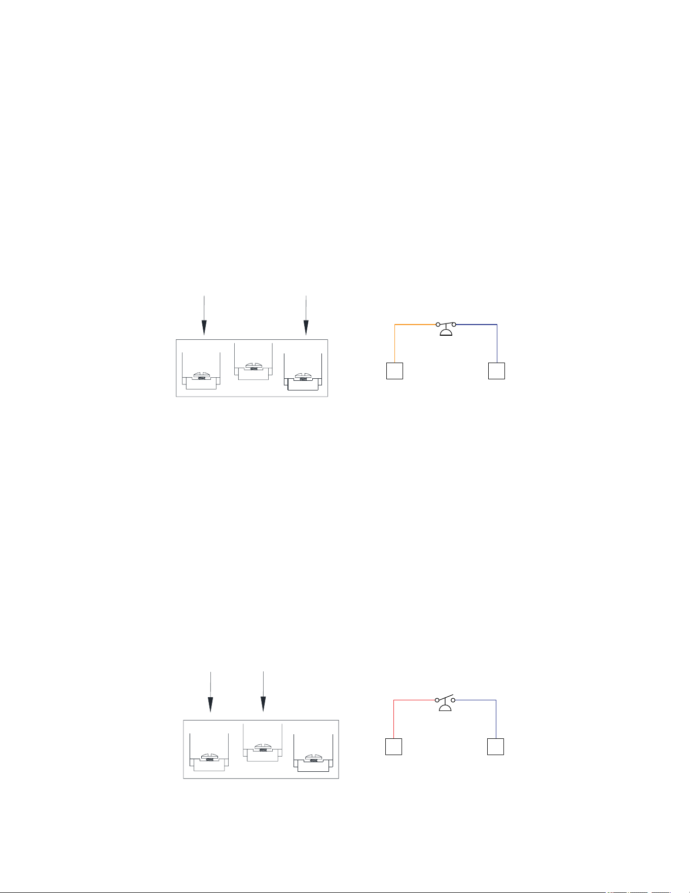
130
High Gas Pressure Switch (PS-03)
1. Turn the unit ON. Reset the lever on the switch. Gas pressure must be lower in the chamber for the
reset latch to be set properly. Verify the high gas pressure switch is set to 12 in. w.c.
2. Remove the cover. Make sure the wiring is set up for Normally Closed (N.C.) contact (Figure 65).
3. Verify the ON/OFF gas valve, and modulating valve is set properly. Refer to “Start-Up Procedure
Heating” on page 83.
4. Check for voltage:
• Back probe connector J13 pin 4 to ground. There should be 24-28V AC.
• Back probe connector J13 pin 11 to ground. There should be 24-28V AC.
- If the voltage reading is incorrect, check the wiring for an open or short circuit. If the wiring is
correct, the switch has failed. Replace the switch.
- If the voltage reading is correct, and the switch reset corrected the fault, there may have been an
intermittent fault.
Figure 65 - High Gas Pressure Switch
Low Gas Pressure Switch (PS-04)
1. Turn the unit ON. Verify the inlet pressure gauge is reading the correct pressure.
• Natural gas - 7 in. w.c. – 14 in. w.c.
• Propane - 11 in. w.c. – 14 in. w.c.
NOTE: If the reading is incorrect, contact the gas supply company.
2. Reset the lever on the switch. Gas pressure must be higher in the chamber for the reset latch to be set
properly. If the reset did not work, continue with the next step.
3. Remove the cover. Make sure the wiring is set up for Normally Open (N.O.) contact (Figure 66).
4. Check for voltage:
• Back probe connector J13 pin 3 to ground. There should be 24-28V AC.
• Back probe connector J13 pin 10 to ground. There should be 0V AC.
- If the voltage reading is incorrect, check the wiring for an open or short circuit. If the wiring is
correct, the switch has failed. Replace the switch.
- If the voltage reading is correct, and the switch reset corrected the fault, there may have been an
intermittent fault.
Figure 66 - Low Gas Pressure Switch
C
NO
NC
4 11
PS-03
C
NC
BL
OR
Connector J13
C
NO
NC
3 10
PS-04
C
NO
BL
RD
Connector J13
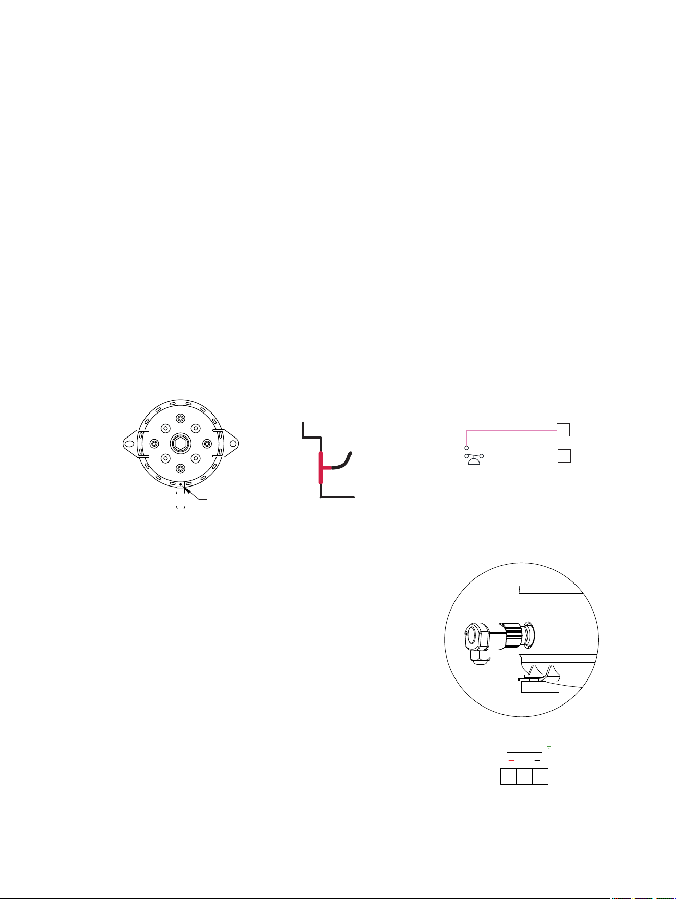
131
Vent Proving Switch (PS-01)
1. Verify wiring is connected properly.
2. Check that the vent tubing is routed correctly. Make sure the tube is not pinched or clogged.
3. Verify the bleed hole is not clogged (Figure 67). The bleed hole reduces condensation build-up in the
switch and tubing.
4. Make sure the unit is OFF. Check the switch. Remove electrical connections. Check for continuity
between pin “C” to pin “NO”. There should be no continuity.
- If there is continuity, the switch has failed. Replace the switch.
- If there is no continuity, re-connect the electrical connections. Continue to the next step.
5. Connect a manometer between the pressure switch and hose. Turn the unit ON. Monitor the
manometer. Verify the value (w.c.) on the switch is correct.
- If the reading is below the value, there is an issue with the vacuum. Refer to “HMI Fault Codes”
on page 115 for more information.
- If the reading is above the value, continue to the next step.
6. With the unit ON. Check for voltage:
• Back probe connector J7 pin 14 to ground. There should be 24-28V AC.
• Back probe connector J7 pin 10 to ground. There should be 24-28V AC.
- If the voltage reading is incorrect, check the wiring for an open or short circuit. If the wiring check is
correct, the switch has failed. Replace the switch.
- If the voltage reading is correct, there may have been an intermittent fault.
Figure 67 - Vent Proving Switch
Oil Level Sensor (Sen-1)
Figure 68 - Oil Level Sensor
Refer to “Compressor Information” on page 52 for more
information on oil level sensor (Figure 68).
1. Verify the compressor is not running. Remove the oil level sen-
sor from the compressor.
2. Turn the unit ON. Verify the compressor is OFF by pressing
OFF on the LCP panel.
3. Go to Service > Open/Closed Status > Inputs > Oil Sensor: The
status should be NC.
- If the OLS diagnostic tool (120Z0560) is available, insert tool
over the optical sensor. The status should change to NO.
- If the OLS diagnostic tool (120Z0560) is not available, place a
light source tightly over the optical sensor. The status should
change to NO.
4. Verify checks:
- If the reading does not change, replace the sensor.
- If the reading changes (sensor is good), and an oil boost has
not cleared the fault, check for low oil or leaks in the system.
Bleed
Hole
Hose to Pressure
Switch
Hose to Inducer
Hose to
Manometer
10
14
J7
PS-01
NO
C
PK
OR
789
J36
SEN-1
VOUT
COM
24V
GR
RD
BK
WH
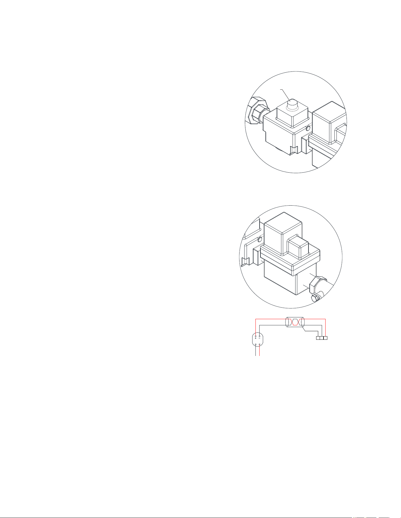
132
Main (On/Off) Gas Valve (VA-01)
Figure 69 - Main Gas Valve
The main gas valve (Figure 69) is located in the burner cabinet.
Units that use 500MBH and larger furnaces are equipped with two
shut-off valves internal to a single body.
1. Make sure the wiring is connected properly.
2. Make sure the gas valve is ON.
3. Turn the unit ON. Check for voltage. Check for voltage across
the pins on the gas valve. There should be 24-28V AC.
- If the voltage reading is incorrect, check the wiring for an
open or short circuit.
- If the voltage reading is correct, the gas valve may be faulty.
Modulating Gas Valve (VA-05)
Figure 70 - Modulating Gas Valve
The modulating gas valve (Figure 70) is located in the main
burner cabinet.
1. Make sure the wiring is connected properly. Check the
wiring using a multi-meter for open or short circuits.
• Terminal 1 – Signal (+) to J7 pin 6
• Terminal 2 – Signal (-) to J7 pin 7
• Terminal 3 – Power 24V DC (+) to H4
• Terminal 4 – Power (-) to N4
- If any damaged wiring is found, repair or replace.
- If any open or short circuits are found, repair or
replace.
- If any wiring is connected incorrectly, correct the
wiring.
NOTE: The wiring connection is polarity sensitive.
2. Make sure the DIP switches are all in the OFF position
(factory setting). This will set the valve to receive a 0-10V
DC signal. If the unit is set up for an analog control
system, refer to Table 14.
3. Make sure the valve has been adjusted properly. Refer to
“Start-Up Procedure Heating” on page 83.
4. If the unit has been running, restart the unit. Check for voltage:
• Connector J7 pin 6 to ground. There should be 10V DC. The voltage reading will drop after the unit has
been running.
• Check for voltage between H4 to N4 on the terminal block. There should be 24-28V AC. This voltage
reading will be constant.
- If the voltage reading is incorrect, check voltage to the IBT control board.
- If the voltage reading is correct, there may be an issue with the modulating valve.
Main Gas
Valve
VA-05
P1
P2
RD
GY
RD
BK
STP Wire
RD
BK
J7
678
SHD
133
Flame Safety Control (FSC-01)
The FSC is located in the main control cabinet.
1. Verify wiring and connections are properly connected (Figure 71).
2. Turn the unit ON. Use the HMI to set the unit in test mode.
• Service > Test Menu > Test Heating > Run Low Fire Test > Stages All
• Refer to “Flame Safety Control (FSC)” on page 86 for operation of sequence.
Determine the symptom below:
3. Turn the unit ON. If the LED is blinking, verify the fault:
• Steady ON = Internal controller failure
• 1 flash = Airflow fault. 2 flashes = Flame without call for heat. 3 flashes = Ignition lock out
Figure 71 - FSC Wiring
Symptom Action
Control does not start • Check wiring.
• Check for a 24V AC transformer failure.
• Check circuit breaker.
• Check LED light.
Thermostat ON – no spark • Check wiring to thermostat input (TH).
• Faulty thermostat.
• Check LED light.
Blower ON – no Trial For Ignition (TFI) after purge
delay
• Check wiring.
• Check for flame fault.
• Air flow fault, check tubes and connections to
MUA Board airflow switch.
• Check connection at PSW terminal.
• Faulty control (Check voltage between L1 and
IND. There should be 24V AC).
Valve ON – no spark during TFI • Check wiring.
• Shorted ignitor electrode.
• Check cable to ignitor.
Spark ON – valve OFF • Check wiring.
• Valve coil open.
• Check voltage at V1.
Flame during TFI – no flame sensed after TFI • Check flame rod position.
• Check cable to flame rod.
• Poor ground connection at burner.
• Poor flame.
123456789
101112131415161718
PSW
TH
IND
V1
V2
HV
S1
G
R
L
FSC-01
RD
BK
PR
YW
BR
GY
FR-01
IGNITOR
GTO WIRE
OR
J7
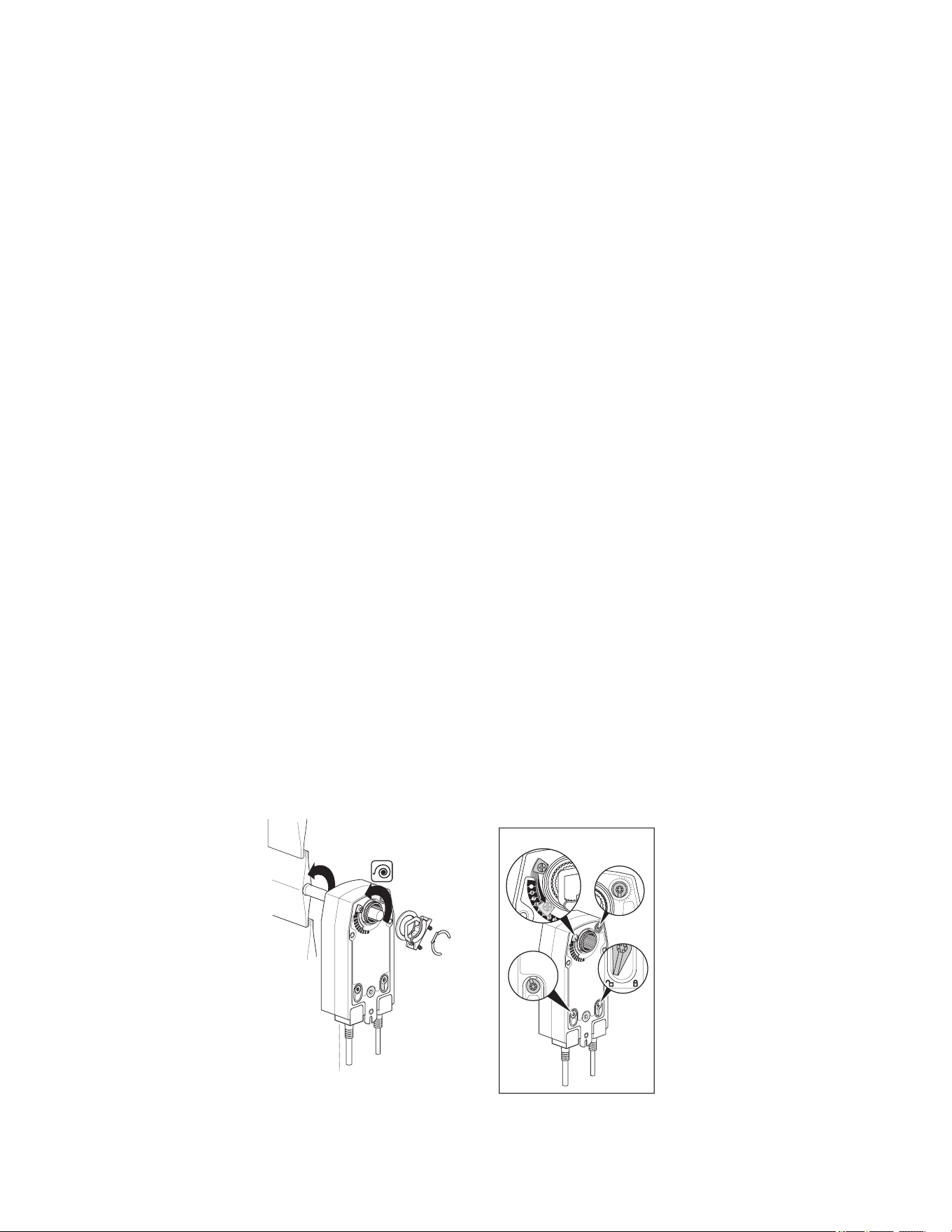
134
Intake Damper Motor Assembly (MT-06)
1. Verify the wiring is correct.
2. Check the wiring for open or short circuits.
3. Verify the positive signal from J18 pin 2 is connected to the assembly at pin 3.
4. Verify the negative signal from J18 pin 9 is connected to the assembly at pin 1.
5. Test the damper rotation. Turn the unit ON. Use the HMI to monitor the movement of the damper.
• User Settings > Outdoor Air Voltage > 10V (default).
• Adjust the voltage setting and monitor the damper movement.
- If the damper movement and voltage reading are correct, test is complete.
- If the damper movement and voltage reading are incorrect, continue to the next step.
6. Check transformer voltages.
- If there is an issue with the transformer or wiring, repair or replace.
- If the transformer check is good, check for mechanical failures.
Field installation/adjustment
1. Rotate the damper shaft to its fail-safe position (closed). Mount the actuator with the counterclockwise
“CCW” out. Refer to Figure 72.
2. If the universal clamp is not on the correct side of the actuator, move it to the correct side.
3. Slide the actuator onto the shaft. Position the clamp so that the pointer of the tab is at the top of the
rotation.
4. Lock the clamp to the actuator using the retaining clip.
5. Tighten the nuts on the V-bolt. Torque to 6-8 ft-lb.
6. Secure to strap.
7. Make sure the rotation is set correctly. Y = 0 set to CCW.
8. Test the spring return damper rotation.
• You can use the crank handle to test manually.
• Turn the unit ON. Use the HMI to monitor the movement of the damper.
• Service > Test Menu > Test Misc > Outdoor Air
• Adjust the voltage setting and monitor the damper movement. 0V – Outdoor air dampers closed;
10V – Outdoor air dampers open.
- If the damper operates properly, the installation is correct.
- If the damper operates incorrectly, adjust as required. If adjustment cannot be made, check the
wiring is correct. Verify to the unit’s wiring schematics.
Figure 72 - Intake Damper Motor Assembly
CCW
CCW
.2
.8
CCW CW
35° ... 95°
9
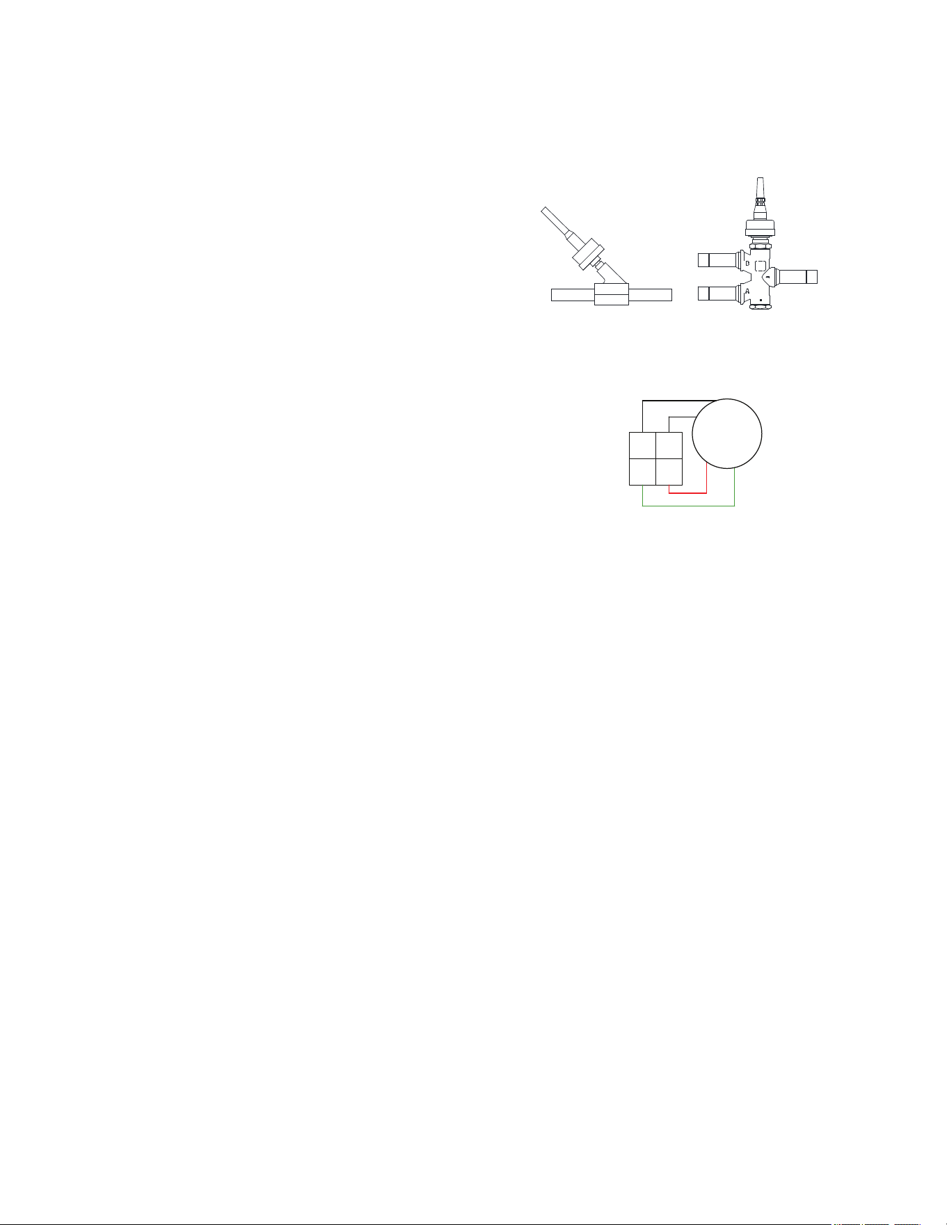
135
Hot Gas Reheat Valve (HG-1/HG-2)
Figure 73 - Hot Gas Reheat
Units with a single reheat valve, HG-1 will be a three-way
valve. Units that use dual reheat valves will have HG-1 in-
line to the reheat coil inlet and HG-2 in-line to the outdoor
(condensing) coil inlet. Refer to Figure 73 for valve
differences.
Power the unit OFF. Verify there is no damage to the wiring.
Check the wiring connections to the MUA board connector,
verify wiring connections to the schematic. Make sure all
connections are secure and connected.
Electronic Expansion Valve (EEV-1)
Figure 74 - EEV Wiring Reference
The Electronic Expansion Valve (EEV-1) wiring (Figure 74) is
connected to the MUA Board.
1. Power the unit OFF. Verify there is no damage to the wiring.
Make sure all connections are secure and connected.
2. Use a multi-meter to measure the resistance in the electronic
expansion valve harness from:
• The black wire to white wire. There should be 90-100 ohms.
• The red wire to green wire. There should be 90-100 ohms.
• The white wire to ground. There should be infinite resistance (open circuit).
• The black wire to ground. There should be infinite resistance (open circuit).
• The red wire to ground. There should be infinite resistance (open circuit).
• The green wire to ground. There should be infinite resistance (open circuit).
- If the readings are incorrect, there may be an issue with the electronic expansion valve. Replace
EEV if necessary.
- If the readings are correct and there are no issues with the electronic expansion valve, there may be
an issue with the superheat controller.
In-Line Valve
Three-Way Valve
2
4
1
3
J34
EEV-01
WH
BK
GR
RD
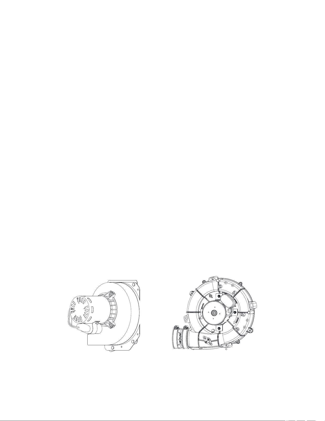
136
Power Vent (MT-02)
1. If the power vent motor is not operating properly, power the unit OFF.
2. Verify there is no damage to the vent proving switch or vent tube.
3. Verify there is no damage to the wiring, motor or capacitor. Make sure all connections are secure and
connected. Verify wiring connections to the schematic. If
damage is found, replace the damaged
component(s).
4. Check the motor’s electrical circuit.
For standard furnaces (Figure 75):
Disconnect the wiring connections from pin J17 and pin J21. Power the unit ON. Check for voltage from pin
J17 to pin J21 on the board. There should be 115-120V AC.
- If the voltage reading is incorrect, verify there is 120V AC to the circuit board.
- If the voltage reading is correct, check the motor’s capacitor. If the capacitor is OK, there may be
an issue with the power vent motor.
For 400HE (High Efficiency) Furnaces (Figure 75):
1. Power the unit OFF. Check the ground circuit on the five pin connector. Check the ground circuit on
the three pin connector. If there is an issue with the ground circuit, repair the circuit. If there is not an
issue with the ground circuit, power the unit ON.
2. With the unit powered ON, check for 24V DC between the (+) and (-) terminals. If the voltage reading
is incorrect, check the 24V DC power supply.
3. Check the PWM signal from the EC+ to ground. The voltage reading should vary. If the voltage reading
is incorrect, verify connections to the circuit board.
4. Check for 120V AC between the H and N terminals. If the voltage reading is incorrect, check the circuit
breaker and the main transformer (TR-01).
5. Check the 24V AC HE Furnace Relay (RE-B). When the relay is actuated, check the following:
• Black wire terminal to ground. There should be 120V AC.
• Red wire terminal to ground. The voltage will vary.
- If the voltage reading is incorrect, the relay may have failed.
- If the voltage reading and all other checks are within specifications, there may be an issue with the
power vent motor.
Figure 75 - Power Vent Motor
Standard Power Vent
High Efficiency Power Vent

137
MAINTENANCE
WARNING: DO NOT ATTEMPT MAINTENANCE ON THIS EQUIPMENT UNTIL THE
ELECTRICAL SUPPLY HAS BEEN COMPLETELY DISCONNECTED AND THE MAIN
GAS SUPPLY VALVE HAS BEEN TURNED OFF.
To guarantee trouble-free operation of this unit, the manufacturer suggests following these guidelines.
Most problems associated with failures are directly related to poor service and maintenance.
Record any maintenance or service performed on this unit in the documentation section located at the end
of this manual.
General Maintenance
• Fan inlet and approaches to ventilator and coils should be kept clean and free from any obstruction.
Clean both the indoor and outdoor coils regularly to maintain unit efficiency.
• Motors are normally permanently lubricated. Check bearings periodically. If they have grease fittings,
lubricate each season. Use caution when lubricating bearings, wipe the fittings clean, the unit should
be rotated by hand while lubricating. Caution: Use care when touching the exterior of an operating
motor. Motors normally run hot and may be hot enough to be painful or cause injury.
• All fasteners should be checked for tightness each time maintenance checks are performed prior to
restarting unit.
• Fans require very little attention when moving clean air. Occasionally oil and dust may accumulate
causing imbalance. If the fan is installed in a corrosive or dirty atmosphere, periodically inspect and
clean the wheel, inlet, and other moving parts to ensure smooth and safe operation.
• The Energy Wheel will require very little attention when moving clean air. Occasionally oil and dust
may accumulate, degrading performance. If the ERV is installed in a dirty atmosphere, periodically
inspect and clean the wheel, belt, and other moving parts to ensure smooth and safe operation.
• Before each heating season, verify that the drain on the bottom of each common flue box of every
furnace in the unit is clear.
Every 3 Months
Filters need to be cleaned and/or replaced quarterly, and more often in severe conditions. Washable
filters, located in the intake louver or ERV module, can be washed in warm soapy water. When re-installing
filters, be sure to install with the same size and rated filter and with airflow in the correct direction as
indicated on the filter.
138
Heating Season
• Verify that the drain on the bottom of the flue box in the unit is clear.
• Inspect bolts and set screws for tightness. Tighten as necessary.
• Inspect the wiring on the unit and replace components where necessary.
• Inspect motor for cleanliness. Clean exterior surfaces only. Remove dust and grease from the motor
housing to ensure proper motor cooling. Remove dirt and grease from the wheel and housing to
prevent imbalance and damage.
• The heat exchanger should be checked for cracks. The heat exchanger should be replaced
immediately if cracks are detected. With a soft cloth, remove any built-up dirt or oil on the exterior
surface of the heat exchanger.
• Inspect the combustion blower motor for cleanliness. Clean exterior surfaces of the combustion blower
motor only. Removing excess dust and grease guarantees proper motor cooling.
• Before each heating season, examine the burner and gas orifices. Inspect burner ports for foreign
debris. Check the heat exchanger, and spark igniter for cleanliness. Use a wire brush to remove any
soot, dirt, or grease from the burner or orifices.
• If equipped with an ERV, inspect the energy wheel, belt, and drive motor. Inspect for foreign debris or
residue build-up, segments of the energy wheel can be removed and washed clean with warm water.
Cooling Season
• Before each cooling season, verify that the drain on the bottom indoor coil drain pan is clear. Inspect
bolts and set screws for tightness. Tighten as necessary.
• Inspect the wiring on the unit and replace components where necessary.
• Inspect motor for cleanliness. Clean exterior surfaces only. Remove dust and grease from the motor
housing to ensure proper motor cooling. Remove dirt and grease from the wheel and housing to
prevent imbalance and damage.
• Inspect the indoor and outdoor coil for dirt and bent fins. Clean or replace as necessary, refer to “Coil
Cleaning Procedure” on page 139.
• Check the outdoor fans for proper rotation and operation. Clean all debris from fan guards.
• Inspect all return air and fresh air dampers and linkage to ensure free operations. Lubricate where
necessary.
• With the unit running, check and record the ambient temperature, superheat, compressor suction, and
discharge pressures. Record this data on the back of this manual.
• If equipped with an ERV, inspect the energy wheel, belt, and drive motor. Inspect for foreign debris or
residue build-up, segments of the energy wheel can be removed and washed clean with warm water.
NOTE: Do NOT release refrigerant to the atmosphere! If adding or removing refrigerant is required,
the service technician must comply with all federal, state, and local laws.
Maintenance Quick Reference Chart
Component Maintenance Interval
Filters Clean or replaced. Every 3 months
Damper assembly Inspect and clean louvers and gutters. Every 3 months
Drain Pans Clean and clear of obstruction. Every heating/cooling season
Bolts and Screws
Inspect bolts and screws.
Verify all hardware is secure and tight.
Every heating/cooling season
Wiring and Electrical Inspect all wiring, and electrical components. Every heating/cooling season
Blower Motor Inspect motor for cleanliness, and proper rotation. Every heating/cooling season
Heat Exchanger Inspect for cracks or damage. Every heating/cooling season
Power Vent Motor Inspect motor for cleanliness. Every heating/cooling season
Burner and Gas Orifices Inspect for cleanliness. Every heating/cooling season
Indoor/Outdoor Coil Check for damaged fins and cleanliness of the coil. Every heating/cooling season
Outdoor Fans Check for proper rotation, operation, and cleanliness. Every heating/cooling season
Damper Assembly Inspect the linkage and movement. Every heating/cooling season
Unit Operation Verify the unit pressures. Refer to “Basic Service” on page 109. Every heating/cooling season

139
Coil Cleaning Procedure
Do not use a pressure washer or high-water pressure when cleaning the coil.
Always use water to rinse the coil down before using third party cleaning solutions. The use of cleaning
solutions and chemicals should be used cautiously; overuse will cause damage to the equipment. If the
coil cannot be cleaned with water only, follow the below procedure to clean the coil.
Caution: Do not use coil cleaning solution without diluting per cleaning solution manufacturer’s
dilution ratios and directions. Use a non-acidic, low/mild alkaline cleaner specified for washing and
cleaning aluminum/copper coils. Coil cleaners can be aggressive products. If not diluted properly
and rinsed thoroughly, damage to equipment will occur.
NOTE: Always wear eye protection, gloves, and other protective clothing when using cleaning
solutions. Avoid breathing solution and mist. E-coated coils must be cleaned per the e-coating
manufacturer’s instructions.
1. Shut the system OFF. Spray the coil surface with only water before applying the cleaning solution to
rinse off loose residue. Allow the water to soak for 10-20 minutes to loosen surface residue.
2. Apply the diluted cleaning solution to the coil.
3. Allow the cleaning solution to saturate the coil for no more than 5 minutes.
4. Thoroughly rinse the cleaning solution from the coil with only warm water (~100°F) until all signs of
residue are eliminated (it should not be brackish or contain excessive dissolved minerals). Verify the
coil is clean, and no foam deposits are present. Repeat steps 1-4 if the coil is not sufficiently clean.
5. Allow the unit to dry completely prior to turning the electrical power on or returning the unit to service.
6. Always clean the following items thoroughly with water once the system is back to service: tools,
sprayer, roof, nearby areas, and equipment that may have come in contact with cleaning solution, etc.
When cleaning coils, specifically where considerable foaming solution deposits are present, it is
essential to rinse the coil, equipment, and surrounding areas thoroughly. Many coil cleaners can
be aggressive products, and residual left behind can be corrosive and damage equipment.
Extensively rinse coils from the bottom of the equipment and all other surrounding metal surfaces.
Never allow the foam to rest or soak in an area, whether on a roof surface, surrounding areas, or
nearby equipment.
Re-Setting of the Furnace Unit
If the flame safety control is locked out (Spark igniter fails or no gas supply), reset the unit by:
1. Turn OFF Power to the unit.
2. Turn Power to the unit back ON.
Emergency Shutdown of Unit
To shut down the unit in the event of an emergency, do the following:
1. Turn power OFF to the unit from main building disconnect.
2. Turn the external disconnect switch to the OFF position.
3. CLOSE the inlet gas valve located on the heater.
Prolonged Shutdown of Unit
For prolonged shutdown, the following steps should be done:
1. Turn the external disconnect switch to the OFF position.
2. CLOSE the inlet gas valve located on the heater.
To re-start the unit, the following steps should be done:
1. Turn the external disconnect switch to the ON position.
2. OPEN the inlet gas valve located on the heater.
140
Filters
NOTE: Quantity subject to change based on filter options. Optional 4” thick filters available upon
request.
Table 17 - Louvered Intake Filter Quantity Chart (Washable)
Unit Housing Size 16” x 20” x 2” 16” x 25” x 2” 20” x 20” x 2” 20” x 25” x 2”
Size 1 2 x x x
Size 2 x x x 2
Size 3 x 4 x x
Size 4 x x 8 x
Unit Housing Size 16” x 20” x 2” 16” x 25” x 2”
Size 1 ERV 4 x
Size 2 ERV 4 x
Size 3 ERV x 4
Size 4 ERV 8 x
Table 18 - Internal Filter Quantity Chart (Throw Away)
Unit Housing Size 16” x 16” x 2” 16” x 20” x 2” 20” x 20” x 2” 20” x 25” x 2”
Size 1 4 x x x
Size 2 x 4 x x
Size 3 x x x 4
Size 4 x x 12 x
Unit Housing
Size
16” x 16” x 2” 16” x 20” x 2” 20” x 20” x 2” 16” x 25” x 2” 25” x 25” x 2”
Size 1 ERV 4 x 4 x x
Size 2 ERV x 4 2 x x
Size 3 ERV x x x 8 x
Size 4 ERV x 16 x x x

141
Maintenance Record
Date Service Performed

142
Maintenance Record
Date Service Performed
143
Start-Up and Maintenance Documentation
START-UP AND MEASUREMENTS SHOULD BE PERFORMED AFTER THE SYSTEM HAS BEEN AIR
BALANCED AND WITH THE COOLING ON (Warranty will be void without completion of this form).
Job Information
Unit Information
Maintenance Record
Date of Visit
*If measured amps exceed the FLA rating on the nameplate, fan RPM must be reduced to decrease
the measured amps below the nameplate FLA rating.
Job Name Service Company
Address Address
City City
State State
Zip Zip
Phone Number Phone Number
Fax Number Fax Number
Contact Contact
Purchase Date Start-up Date
Name Plate and Unit Information Field Measure Information
Model Number Motor Voltage
Serial Number Motor Amperage*
Unit Voltage MUA Blower RPM
Unit Hertz Ambient Wet Bulb Temp (°F)
Unit Phase Ambient Dry Bulb Temp (°F)
Unit FLA Cond 1 Suction Pressure PSI
Unit Supply HP Cond 1 Suction Temperature (°F)
Gas Type Cond 1 Liquid Pressure PSI
Min. Btu/Hr Cond 1 Liquid Temperature (°F)
Max. Btu/Hr Cond 1 Subcooling (°F)
Measured Temp Rise (°F) Cond 1 Superheat (°F)
Airflow Direction - Correct or Incorrect?
Field Measured Information – Initial Readings Field Measured Information – Final Readings
Motor Voltage Motor Voltage
Motor Amperage* Motor Amperage*
MUA Blower RPM MUA Blower RPM
Ambient Wet Bulb Temp °F Ambient Wet Bulb Temp °F
Ambient Dry Bulb Temp °F Ambient Dry Bulb Temp °F
Cond 1 Suction Pressure PSI Cond 1 Suction Pressure PSI
Cond 1 Suction Temperature °F Cond 1 Suction Temperature °F
Cond 1 Liquid Pressure PSI Cond 1 Liquid Pressure PSI
Cond 1 Liquid Temperature °F Cond 1 Liquid Temperature °F
Cond 1 Subcooling °F Cond 1 Subcooling °F
Cond 1 Superheat °F Cond 1 Superheat °F
144
Maintenance Record
Date of Visit
Maintenance Record
Date of Visit
Maintenance Record
Date of Visit
*If measured amps exceed the FLA rating on the nameplate, fan RPM must be reduced to decrease
the measured amps below the nameplate FLA rating.
As a result of our dedication to constant improvements and quality, the MANUFACTURER reserves the
right to update specifications without notice. Please refer to MANUFACTURER’S website for up to date
documentation.
Field Measured Information – Initial Readings Field Measured Information – Final Readings
Motor Voltage Motor Voltage
Motor Amperage* Motor Amperage*
MUA Blower RPM MUA Blower RPM
Ambient Wet Bulb Temp °F Ambient Wet Bulb Temp °F
Ambient Dry Bulb Temp °F Ambient Dry Bulb Temp °F
Cond 1 Suction Pressure PSI Cond 1 Suction Pressure PSI
Cond 1 Suction Temperature °F Cond 1 Suction Temperature °F
Cond 1 Liquid Pressure PSI Cond 1 Liquid Pressure PSI
Cond 1 Liquid Temperature °F Cond 1 Liquid Temperature °F
Cond 1 Subcooling °F Cond 1 Subcooling °F
Cond 1 Superheat °F Cond 1 Superheat °F
Factory Service Department | Phone: 1-866-784-6900 | Fax: 1-919-554-9374
