© Copyright 2017 Zoeller
®
Co. All rights reserved.
SECTION: Z8.00.250
ZM2818
0617
Supersedes
0615
INSTALLATION PROCEDURES
Z-RAIL
®
DISCONNECT SYSTEMS
1-1/4", 1-1/2", 2" AND 3" NPT VERTICAL DISCHARGE PUMPS
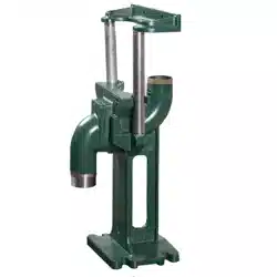
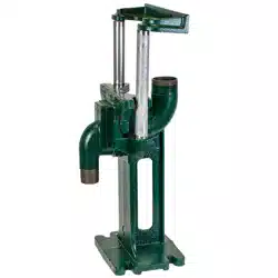
General Information: These instructions cover Zoeller's Z-Rail
®
Disconnect Systems. These disconnects are designed for pumps
with a threaded vertical discharge. We also offer rail systems
designed for anged discharge pumps, see ZM1170.
General Construction: Major system components, disconnect tting,
guide rail plate and upper rail support bracket are made of powder
coated epoxy ductile iron. The optional individual stabilizer bracket
is stainless steel.
Lifting Cable: Stainless steel lifting cables are available. These cables
are designed to attach to the top of the pumps and allow the pumps
to be safely hoisted up and down guide rails. For 6160, 6180, 6280,
6290 and 7010 series, use P/N 10-0789 stainless steel lifting bail to
properly position lifting cable on top of pump.
Rail Support Bracket: The system is designed to be used with 3/4"
schedule 40 galvanized or stainless steel rail pipe, which is provided
by others. A top rail support is designed to be mounted to the hatch
frame. Intermediate brackets are available for deep installations. It
is recommended that if the rail length is over 12 feet, an intermediate
bracket be installed.
INSTALLING RAIL SYSTEM PARTS
Disconnect Fitting and Rails:
1. Lower the disconnect tting into the basin.
2. Position the disconnect tting by dropping a plumb line from
the center of pipe supports, located on the upper rail support, to
center of rail pins protruding from the tting. Level its mounting
ange in two directions 90° to each other. Mark the position of
the tting, holding down bolts through the holes in the base.
3. Move the tting aside to allow for installation of 1/2" mounting
bolts (not included). Secure tting in mounting bolts.
4. Cut the 3/4" pipe guide rails (supplied by others) to the proper
length and install them between the upper rail support at the top
of the basin and the pins on the tting. The guide rails are to be
3/4" pipe schedule 40, galvanized or stainless steel.
IMPORTANT: Discharge pipe and guide rails must be parallel if
intermediated guide bracket is used.
INSTALLING INTERMEDIATE GUIDE BRACKET (Required for basin
depths greater than 12'.)
1. Remove guide rails and cut a piece from each one. These pipes
must be exactly the same length and of a length that will permit
installing the intermediate guide bracket in the desired location.
2. Place the cut pieces of pipe over the guide rail pins located in
the base.
3. Set the intermediated guide bracket in position with guides into
pipe. Put u-bolt around discharge pipe and tighten lightly.
4. Measure from joint on plug on intermediate guide bracket to joint
on plug on top rail support and cut two (2) rails to the length. Put
rails in place and tighten screws in top of support.
5. Recheck rails; they must be straight and plumb. Move intermediate
guide bracket if necessary to perfectly align rails. After alignment
is secured, tighten nuts on u-bolt.
6. If a second intermediate guide bracket is used, the above procedure
is followed for installation.
ATTACHING THREADED DISCONNECT TO PUMP
1. Remove pump elbow from the guide rail plate. Three cap screws
hold elbow to the guide rail plate.
2. Thread elbow into pump volute.
3. Reassemble guide rail plate to pump elbow. Ensure o-ring between
guide rail plate and pump elbow remains intact. Tighten 3 cap
screws.
4. Attach the lifting bail (P/N 10-0789) to the pump, if not factory
installed.
5. The guide rail can now be slid down the rail pipe for mounting
the disconnect tting
INSTALLING PUMP AND DISCONNECT
IMPORTANT: When lifting pump up and down the guide rails, the pump
should be slightly tipped forward toward the discharge and plumb
(vertical) from side to side when facing the discharge.
Position pump so the guide rails are located in the slots of the guide
plate. Slowly lower the pump down the guide rails to the base. The
angled surface of guide rail plate should come to seat in the inclined
surface on the arms.
After lowering the pump down the guide rail, secure the upper end of
the lifting cable to the top rail support to keep it from falling into the pit.
Notice to installing contractor: Instructions must remain with installation.
Register your
Zoeller Engineered Product
on our website:
http://reg.zoellerengprod.com/
MAIL TO: P.O. BOX 16347 • Louisville, KY 40256-0347
SHIP TO: 3649 Cane Run Road • Louisville, KY 40211-1961
(502) 778-2731 • 1 (800) 928-PUMP • FAX (502) 774-3624
Visit our website:
zoellerengineered.com
Product information presented
here reects conditions at time
of publication. Consult factory
regarding discrepancies or
inconsistencies.
© Copyright 2017 Zoeller
®
Co. All rights reserved.
2"
NPT
DISCHARGE
ELBOW
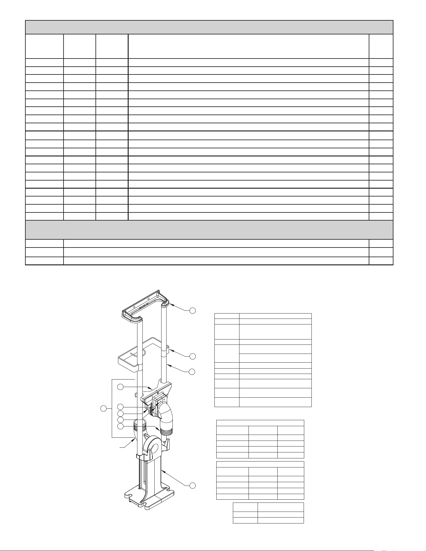
ITEM NO. DESCRIPTION
1 DISCONNECT FITTING
2
COMPLETE SLIDE ASSEMBLY TO
INCLUDE PART NO. 3,4,5,6,7 (SEE
BELOW)
3 PUMP ELBOW
4
DUCTILE IRON GUIDE RAIL PLATE
-NORMAL
BRASS GUIDE RAIL PLATE
-NON-SPARKING
5
SS SCREWS (3)
6 INTERNAL O-RING
7 GUIDE PLATE O-RING SEAL
*8 INTERMEDIATE RAIL SUPPORT-SS
9
UPPER RAIL SUPPORT BRACKET
-DUCTILE IRON OR SS
10
BY OTHERS - TWO 3/4 RAIL
PIPES
SECTION OF RAIL PIPE.
* OPTIONAL - REQUIRED FOR EACH 12'
ITEM 7
PART NO.
SIZE
152387
1-1/4; 1-1/2; 2"
152389 3"
DUCTILE IRON
NON-SPARKING BRASS
1
RAIL SYSTEM
PART NO.
ITEM 2 PART
NO.
SIZE
39-0134 152831
1-1/4" V
39-0131 152830
1-1/2" V
39-0128 152829 2"V
39-0122 152762 3"V
3
5
6
7
4
10
*8
9
2
RAIL SYSTEM
PART NO.
ITEM 2 PART
NO.
SIZE
39-0136 152877
39-0133 152876
39-0130 152875
39-0124 152763
1-1/4" V
1-1/2" V
2"V
3"V
SK2983
* Disconnect tting, guide rail plate, rail guide, upper rail support bracket
** Lifting bails are required on the following models to balance pump and rail plate evenly; other models include proper lifting device.
SPECIFICATIONS
Rail System
Pump
Discharge
Rail
System
Discharge
Materials of Construction* Weight
39-0134 1-1/4" V 2" V Ductile iron, powder coated epoxy 41
39-0135 1-1/4" V 2" V Ductile iron, powder coated epoxy with SS upper rail supports 43
39-0136 1-1/4" V 2" V Powder coated ductile iron / brass for non-sparking 44
39-0143 1-1/4" V 2" V Powder coated ductile iron w/ SS upper rail support / brass for non-sparking 43
39-0131 1-1/2" V 2" V Ductile iron, powder coated epoxy 41
39-0132 1-1/2" V 2" V Ductile iron, powder coated epoxy with SS upper rail supports 43
39-0133 1-1/2" V 2" V Powder coated ductile iron / brass for non-sparking 44
39-0142 1-1/2" V 2" V Powder coated ductile iron w/ SS upper rail support / brass for non-sparking 43
39-0128 2" V 2" V Ductile iron, powder coated epoxy 42
39-0129 2" V 2" V Ductile iron, powder coated epoxy with SS upper rail supports 43
39-0130 2" V 2" V Powder coated ductile iron / brass for non-sparking 43
39-0141 2" V 2" V Powder coated ductile iron w/ SS upper rail support / brass for non-sparking 44
39-0146 2" V 2" V 71 Series Grinder - Powder coated ductile iron 43
39-0148 2" V 2" V 71 Series Grinder - Powder coated ductile iron w/ SS upper rail support 45
39-0147 2" V 2" V 71 Series Grinder - Powder coated ductile iron / brass for non-sparking 43
39-0149 2" V 2" V 71 Series Grinder - Powder coated ductile iron w/ SS rail support / brass for non-sparking 44
39-0122 3" V 3" V Ductile iron, powder coated epoxy 47
39-0123 3" V 3" V Ductile iron, powder coated epoxy with SS upper rail supports 47
39-0124 3" V 3" V Powder coated ductile iron / brass for non-sparking 47
39-0125 3" V 3" V Powder coated ductile iron w/ SS upper rail support / brass for non-sparking 47
ACCESSORIES
Intermediate rail brackets are required for each 12' of basin depth.
39-0139 Intermediate Rail Bracket 1-1/4", 1-1/2" and 2" discharge - Stainless Steel 4
39-0140 Intermediate Rail Bracket 3" discharge - Stainless Steel 4
** 10-0789 SS lifting bail for 6160, 6180, 6280, 6290 & 7010 Series 1
NOTE: Guide Rail Plate for
3" (39-0122) Z-Rail
®
is NOT
threaded (see #4 on drawing)
for bale installation.
© Copyright 2017 Zoeller
®
Co. All rights reserved.
SK3036
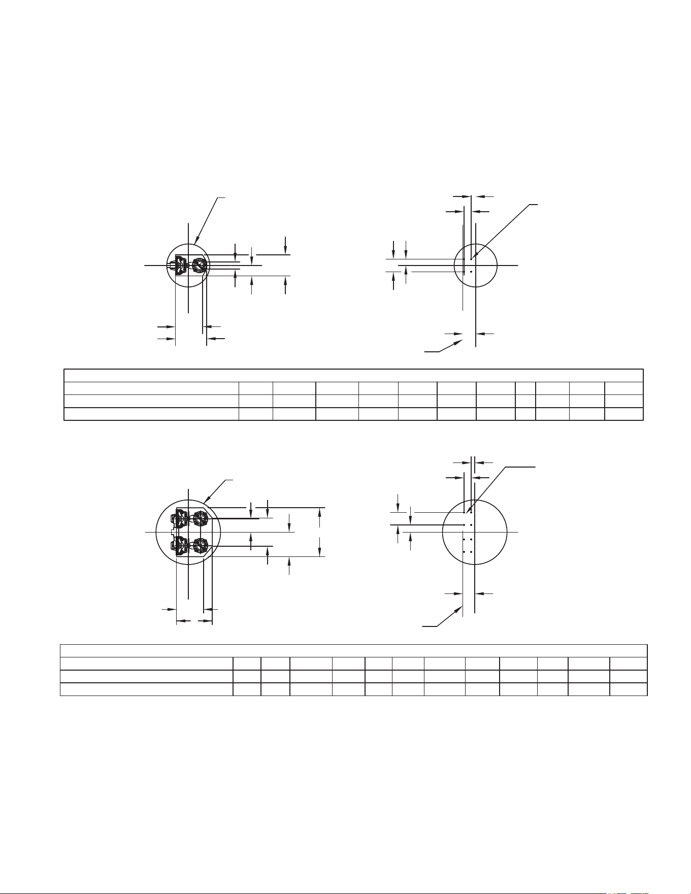
G
F
NOM. SIZE
ZOELLER RAIL SYSTEM SIMPLEX DIMENSIONAL CHART
A B C D E F
G
F
J
D
A
C
B
E
J
K ANCHOR
BOLT (4)
B
C
K ANCHOR
BOLT (8)
A
D
KG
M
1.25"-2" DISCHARGE
17-3/8 15-1/8
NOM. SIZE A B D JC
4
5-7/8
3-1/2 2-1/2
K
1/2
7
C
L
DOOR FRAME
REF. PLANE
L
C
L
C
L
C
DOOR FRAME
REF. PLANE
L
7-1/8
M
J
ZOELLER RAIL SYSTEM DUPLEX DIMENSIONAL CHART
24 INCH DIAMETER MINIMUM SIZE.
27-1/4
4
2 13-5/8 1/2204-1/32
7
1.25"-2" DISCHARGE 7-1/2
36 INCH DIAMETER MINIMUM SIZE.
L
L
E
E
11-3/4
G H
4
H
F
15-1/8
L
6-11/16
H
H
15-3/4
2" 71 SERIES GRINDER & 3" DISCHARGE
26 -
4
12
3-1/2 3-3/8
1/2
7
824 -
2" 71 SERIES GRINDER & 3" DISCHARGE
30
4
7-7/8 15 1/2294
7
7-3/8- 12-7/16-
48 INCH DIAMETER MINIMUM SIZE FOR 71 SERIES.
48 INCH DIAMETER MINIMUM SIZE FOR 71 SERIES.
MADE IN U.S.A.
MADE IN U.S.A.
MADE IN U.S.A.
THE INFORMATION ON THESE DRAWINGS OR WEB PAGES ARE MADE AVAILABLE FOR YOUR USE. HOWEVER, YOU USE THE
INFORMATION AT YOUR OWN RISK. WE BELIEVE THE INFORMATION TO BE CORRECT AND ACCURATE AT THE TIME OF ISSUE.
ZOELLER COMPANY ASSUMES NO LIABILITY, EXPRESSED OR IMPLIED, RESULTING FROM YOUR ACCESSING AND USING THIS
INFORMATION. DUE TO THE CHANGES AND/OR DOWNLOAD PROBLEMS, IT IS YOUR RESPONSIBILITY AND YOU AGREE TO BE
SOLELY RESPONSIBLE TO VERIFY THAT THE INFORMATION IS CORRECT AND ACCURATE FOR YOUR PURPOSES.
LIFT STATION DIMENSIONAL DATA
1-1/4", 1-1/2", 2" AND 3" NPT VERTICAL DISCHARGE PUMPS
Z-RAIL
®
DISCONNECT SYSTEMS

© Copyright 2017 Zoeller
®
Co. All rights reserved.
MAIL TO: P.O. BOX 16347 • Louisville, KY 40256-0347
SHIP TO: 3649 Cane Run Road • Louisville, KY 40211-1961
(502) 778-2731 • 1 (800) 928-PUMP • FAX (502) 774-3624
visit our web site:
zoellerengineered.com